Embed Size (px)
Citation preview

Paralleling Collision Detection on Five-Axis Machining
Cheng-Yan Siao1, Jhe-Wei Lin1, Ting-Hsuan Chien2,* and Rong-Guey Chang1
1Department of Computer Science and Information Engineering, Advanced Institute of Manufacturing with High-Tech Innovations,National Chung Cheng University, Chiayi, 621005, Taiwan
2Department of Computer Science and Information Management, Providence University, Taichung, 433303, Taiwan�Corresponding Author: Ting-Hsuan Chien. Email: [email protected]
Received: 02 March 2021; Accepted: 05 April 2021
Abstract: With the rapid growth of the Fourth Industrial Revolution (or Industry4.0), five-axis machining has played an important role nowadays. Due to theexpensive cost of five-axis machining, how to solve the collision detection forfive-axis machining in real-time is very critical. In this paper, we present a parallelmethod to detect collision for five-axis machining. Moreover, we apply thebounding volume hierarchy technique with two-level bounding volume representthe surface or solid of the object to reduce triangle meshes inside each axis of thefive-axis machine tool, and then matching the operating range limit of the five-axis machine tool itself, delete the no colliding triangle mesh. Additionally, wealso propose some optimization with loop unrolling and prefetching techniquesto improve performance of collision detection. Our approach can reduce theexecution time significantly by computing six separating axes in plan and elevenseparating axis in non-plan between two triangle meshes based on the character-istic of GPUs (Graphics Processing Units) for program acceleration. Our proposedwork consists of kinematic analysis and interpolation for axes to save the numer-ous collision detection for five-axis machining computations. In this experiment,the result shows that using the proposed approach above can achieve approxi-mately 37.1 times speedup than that of CPU.
Keywords: Collision detection; five-axis machining; graphics processing units
1 Introduction
As Industry 4.0 has become the focus of industrial manufacturing, the Computer Numerically Controlled(CNC) machine tools have played an essential role the industry. More advanced machining technologies usefive-axis CNC machining for complicated part fabrication. The Five-axis machine has two rotary tables thatimprove the machining capability and quality. However, five-axis machining has high axial table collidingchances due to the coordinated motion for rotating and translating tables. If the machine tool differsduring machining, it damages the machine itself and delays the productions. Therefore, how to preventaxial table collisions during machining is very important for five-axis machining processes. Owing to theexpensive cost of machine tools, avoiding collision detection has become a critical issue.
This work is licensed under a Creative Commons Attribution 4.0 International License, whichpermits unrestricted use, distribution, and reproduction in any medium, provided the originalwork is properly cited.
Intelligent Automation & Soft ComputingDOI:10.32604/iasc.2021.018252
Article
echT PressScience

There are three types commonly used for five-axis machine tools: table tilting type, spindle tilting type,and table/spindle tilting type. Although the table tilting type is used in this paper for theorem derivation andexplanation, the proposed approach can be applied to other types. Fig. 1 is an example of a commerciallyavailable table tilting type for five-axis machines.
The machine design is usually modeled as STL format that uses triangular facets to describe designedobjects. Each triangular element contains three vertices and a normal facial vector. Most of thecommercially available Computer-Aided Design (CAD) software provide STL format for object designoutput, as shown in Fig. 1(b).
In this paper, we propose a work about the real-time anti-detection to solve the issue mentioned earlier.To achieve this objective, the proposed work consists of the following steps. We first perform the kinematicsanalyses for five-axis motions. The format of the machine structure is modeled as STL used commonly inCAD software. The input is the g-code that represents the tool motions to produce the surface of anobject. Since three-dimensional surface objects are modeled as triangle meshes for digital holography,they are the primitive elements of three-dimensional objects in computers [1]. Hence, the intersection testfor two triangles will determine if the collision will occur. To improve performance, we try to eliminatethe triangle meshes that never collide based on the bounding volume hierarchy [2]. In this manner, wecan reduce the computation amount to save the computation time and thus obtain an ideal speedup. Asthe GPUs have been used widely for many applications, we propose a parallel method to determinewhether two objects in a three-dimension space intersect or not in parallel. Compared with the traditionalway, the proposed similar approach can improve the performance again. Besides, with our domainknowledge and experiences on GPU and CUDA (Compute Unified Device Architecture) programming,we apply some optimization techniques such as loop unrolling, prefetching, alignment, strode access, andinterchanging the bounding volume to improve performance further.
The remainder of the paper is organized as follows. We describe the previous work related to our work inSection 2. Then we present how to reduce the number of triangle meshes based on the bounding volumehierarchy technique in Section 3. Next, we explain how to parallel the collision detection for two objectson the GPU in Section 4. In Section 5, we show the results of our numerical experiments regarding ourproposed algorithm’s performance on GPUs. Finally, we summarize our findings with some concludingremarks in Section 6.
(a) (b)
Figure 1: (a) The table tilting type for five-axis machines, (b) The STL model of the machine
560 IASC, 2021, vol.29, no.2

2 Related Work
2.1 Separating Axis Theorem
Möller [3] designed an efficient algorithm to detect collision for two triangles. Held [4] also presented asimilar algorithm but in a different way. Both of them computed the signed distance of three vertices of atriangle from the plane containing the other triangle. If all the values are the same sign, they do not intersect.Otherwise, they may cross, and the problem is then reduced to an overlap test of two line segmentspositioned on the same line of corner between the two planes containing the triangles. Moller computed aparametric equation of the intersection of two planes, found the intervals for the line that lays inside eachtriangle, and performed a one-dimensional interval overlap test. In contrast, Held reduced the problem to atwo-dimensional triangle/line-segment test after projecting to a convenient plane. Guigue et al. [5] thenfollowed Moller by using an orientated decision defined by a determinant of a 4 × 4 matrix to predict andcompute the signed distance of each vertex from orientated decision. The intersection test is then reduced tocheck the signs of orientated decision. Tropp et al. [6] presented an algebraic approach similar to that of Held,while the key observation is that the set of equations are strongly related to each other. They reused somecomputation results for certain variables based on linear algebra. Then, the common elements of the differentequations can be applied to speed up the solution whilst exploiting the linearity of the matrix operations.Chang et al. [7] adopted Moller’s algorithm based on OBB-based collision detection to improve it. Instead,we use the splitting axis theorem and induce six separating axes in plan and 11 separating line axes in non-plan between two triangle meshes to address this issue, as shown in Fig. 2.
2.2 Bounding Strategies
The idea of decreasing the execution time is to reduce the number of triangle meshes. Ritter proposed thebounding sphere [8] to wrap any irregular object in the form of a sphere. This work can calculate efficientlywith few parameters. Cohen et al. proposed a collision detection method using AABB for the wrappedvolume [9] and projected X, Y, and Z axes of the object. Their work was convenient to set up thewrapping by wrapping the thing with each X, Y, Z projection amount. Later, OBB was proposed by
Figure 2: Six separating lines in the plane and 11 splitting axes in the non-plane between two triangle
IASC, 2021, vol.29, no.2 561

Gottschalk et al. [10] to use the covariance matrix to calculate the three principal axis directions according tothe appearance of the object and then project the three main axis directions, respectively. In this way, thebounding object was similar to the original one, and the number of bounding bodies was significantlyreduced. A k-DOP [11] was a convex polygon in a two-dimensional space or a convex polyhedron in athree-dimensional space that contains an object. It is obtained by moving a set of infinitely distantoriented planes to intersect the object. In addition, bounding this group of points and the smallest shellmust be convex in theory. The convex hull [12] was proposed to bound an object with the smallestsurface area and volume among all the shells. The advantage was that any graph can be simplified into aconvex hull of a group of points. are common bounding volume techniques.
3 Reducing Triangles Meshes with Two-Level Bounding Volume
In general, although it is better to bound an object from left to right, the rough collision detection timebecomes much longer and the memory size must be larger. The AABB is the bounding box aligned with theaxes of the coordinate system. In this paper, we will use AABB to represent a bounding object. For anAABB, min and max mean the left top and the right down of a bounding object. When the object isrotated, the min-max must be computed again. For the collision detection of two AABBs, O1 and O2, O1
and O2 will collide if and only if !(O1.max.x < O2.min.x || O1.min.x > O2.max.x), !(O1.max.y < O2.min.y|| O1.min.y > O2.max.y), and !(O1.max.z < O2.min.z || O1.min.z > O2.max.z).
Considering into this concern account, we choose the AABB bounding volume in this paper because theothers are too complicated during the computation for bounding volume hierarchies. The advantages of AABBare using less memory size, computing bounding sub-volume simply, and achieving a better performance. Wealso use bounding volume hierarchies with AABB to reduce triangle meshes of two objects in the fetching stagewhile using GPU. Moreover, the reduction of triangle meshes can save time to find separating axis numbers.Thus, we first illustrate the AABB bounding volume technique and continue displaying the n level boundingvolume hierarchies with AABB. Because there are many multiprocessors and blocks in GPU, the hardware canschedule blocks to multiprocessors in any order and thus the numerous blocks will be time consuming. For thisgoal, the collision detection will be performed the rough collision detection based on the bounding volumetechnique first and then compute the detailed collision detection stage.
The idea of the n level bounding volume hierarchies with AABB is the rough collision detection inlevels. In other words, we are not concerned whether triangle meshes are overlapping or not. In Fig. 3,there are many sub-AABBs (R2, R3, R4, R5, R6, R7, …) by segmenting the AABB (R1) between object1and object2. Finding the collision regions of two objects is from the maximum size region to theminimum size region. Regions R2, R4, R5 and the regions in R4 and R5 of object1 are not found, becausethe regions do not collide with the regions of the object2. The order relation of finding the areas can bepresented by using breadth-first search (BFS) to search a tree structure. A tree node presents a region,where the bigger areas is the parent node and the smaller areas in it are child nodes. In this manner, thebounding volume hierarchies are models as an n-level tree. In BFS, if R2 in object1 does not be searcheddepending on whether it collides with R2 and R3 in object2 or not, the child and offspring nodes of R2 inobject1 are not searched for them either.
In our design, we use a two level bounding volume hierarchies with AABB. For an example shown inFig. 4, O1 contains two sub-AABBs named S1_O1 and S2_O1 and O2 contains two sub-AABBs named S1_O2
and S2_O2. In the rough collision detection stage, to check whether the two objects collide or not, we onlydetect the collision of O1 and O2. Moreover, if O1 and O2 collide, four cases must be checked: the collisiondetection of S1_O1 and S1_O2, S1_O1 and S2_O2, S2_O1 and S1_O2, and S2_O1 and S2_O2. If S2_O1 andS1_O2 collide, the threads of GPU will be assigned in a CUDA program to detect the collision of trianglemeshes in S2_O1 and S1_O2 in the detailed collision detection stage (see Section 4). As a result, the
562 IASC, 2021, vol.29, no.2

rough collision detection cannot make sure if two AABBs really collide. The detailed collision detectionmust be performed to check it precisely.
4 Parallel Approach
Fig. 5 is the overview that a simulator replicates the five-axis machine tool’s motion and the collisiondetection system is implemented on the GPU to meet the real-time constraint. This section fist depicts theCUDA programming model and then presents how to perform optimization techniques to parallelizecollision detection on GPU. We also show a paralleling algorithm to improve collision detectionperformance on the SIMD (Single Instruction Multiple Data) architecture.
R2
R1
R3
R4 R5 R6 R7
Object1
Object2
R1
R2 R3
R4 R5 R6 R7˙˙˙
Figure 3: The n-level bounding volume hierarchies with AABB
S1_O1 S2_O1
S1_O2 S2_O2
O1
O2
Figure 4: An example for the rough collision detection and the detailed collision detection
Figure 5: The simulator is implemented on CPU and the collision detector is implemented on GPU
IASC, 2021, vol.29, no.2 563

4.1 CUDA Programming Model
CUDA is a parallel computing platform and programming model created by NVIDIA [13]. In Fig. 3, akernel function is composed of the parallel subroutine and the memory model. Implementation of everythread in the grid is the kernel function. A grid is a collection of blocks, and a block is a collection ofthreads. A wrap is a group of 32 threads executed physically in parallel. Two designs need to be noted.Firstly, the wrap-based execution is the effective method on the SIMD architecture. Designing a warp toexecute the same thread effectively uses the SIMD architecture, Otherwise, the performance willdecrease. As an example, because the divergent thread design causes a reduction of parallelism, it ispossible not to use this design. Secondly, the thread number in a block is a multiple of 32. That is abetter design for the performance because the hardware does not need to add more warps to execute. Ifthe thread number in a block is not multiple of 32, it will add more warps to execute and decreaseperformance.
4.2 Performance Improvement
To improve collision detection performance, we perform loop unrolling and prefetch to exploitinstruction level parallelism and loop level parallelism.
4.2.1 Loop UnrollingLoop unrolling can extend the paralleling space by replicating the loop body many times, only adjusting
the loop termination code. We then can find threads enough to be assigned to GPU via dependence analysis.If loops are independent, then they can be executed in parallel. Fig. 6 shows that the loop unrolling techniqueis used to increase the parallel degree.
CPU
/* N triangle meshes on object1M triangle meshes on object2 */
for ( i= 0 ; i< N ;i++){
for ( j= 0 ; i< M ;j++){
/* finding a separating line is form 1 to 17 */ find 1 's separating line;find 2 's separating line;
find 17 's separating line;}
}
GPU
Wrap 0
Loop Unrolling
Figure 6: Loop unrolling can increase the parallelism
564 IASC, 2021, vol.29, no.2

If there are n triangle meshes on object1, and m triangle meshes on the object2, there are m × n threads intotal assigned to execute in parallel. Developers can avoid the thread divergence as much as possible.Therefore, if there are the six separating lines or the 11 separating lines depending on whether they are ina plane or not, they must be checked sequentially whether they can separate two triangle meshes in athread. If there are no separating lines to separate two triangle meshes in a thread, these two objects maycollide. This may result in different execution time for every thread because just finding a separating lineto check collision depends on which separating line can ensure if the collision happen. For a real-timesystem, we considered the worst-case execution time as the performance issue. With the aid of loopunrolling, we can exploit more parallelism to improve performance by executing more threads.
4.2.2 Prefecting MechanismTo improve the memory bandwidth, we propose a prefetching mechanism to solve this problem.
Normally, we can use CUDA API (cudaMalloc (), cudaMemcpy ()) to load data from the memory ofCPU to the global memory of GPU. When the simulator’s cutter of the five-axis machine tool is movedor rotated by motion control, the data in the global memory of GPU must be updated by GPU to detectcollision. Therefore, there is not a bottleneck during collision detection. In Fig. 7, there are six axes X, Y,Z, A, B and Cutter. If the number of triangle meshes of the X axis and Y axis are N and M, N × Mthreads must fetch different data from the X axis and Y axis of GPU’s global memory to execute in parallel.
4.2.3 Alignment and Stride AccessBased on the hardware’s warp-based execution, the maximum number of the threads is 1024 (32 × 32)
for a GPU block [14]. A thread will fetch data from the X axis and Y axis and design a data structure with atwo-dimensional block and a two-dimensional thread. The size of the two-dimensional block is (N/32+1) ×(M/32+1). The row index and the column index of the two-dimensional block ae from 0 to N/32+1 and from
Grid 0 (Detect Collision for X and Y)
Block(0,0)
Wrap 0
Block(0,1) Block(bi,bj)Thread(ti,tj)
Global Memory
X axis
A axis
Y axis
B axis
Z axis
Cutter
T
Collision Flag
Figure 7: A data prefetching model from global memory to execute
IASC, 2021, vol.29, no.2 565
0 to M/32+1, respectively. The size of the two-dimensional thread is 32 × 32, where the row index and thecolumn index are from 0 to 32. Thus, there are 1024 threads in every block. The thread (ti,tj) in the block (bi,bj) fetches data from the index of X axis data is 32 × bi + ti and the index of Yaxis data is 32 × bj + tj. Thus, itis possible to avoid thread divergence and result in a higher parallel degree on GPU because of this design. Ifthe execution result of thread (ti,tj) in the block (bi,bj) is true, the colliding flag in global memory will be set toindicate that the two objects will collide. Therefore, because kth thread in a block fetches kth data in GPU’sglobal memory, the misaligned access pattern and stridden access problems do not occur. Thus, GPU can usethe coalesced memory technique to improve the performance of the fetching data.
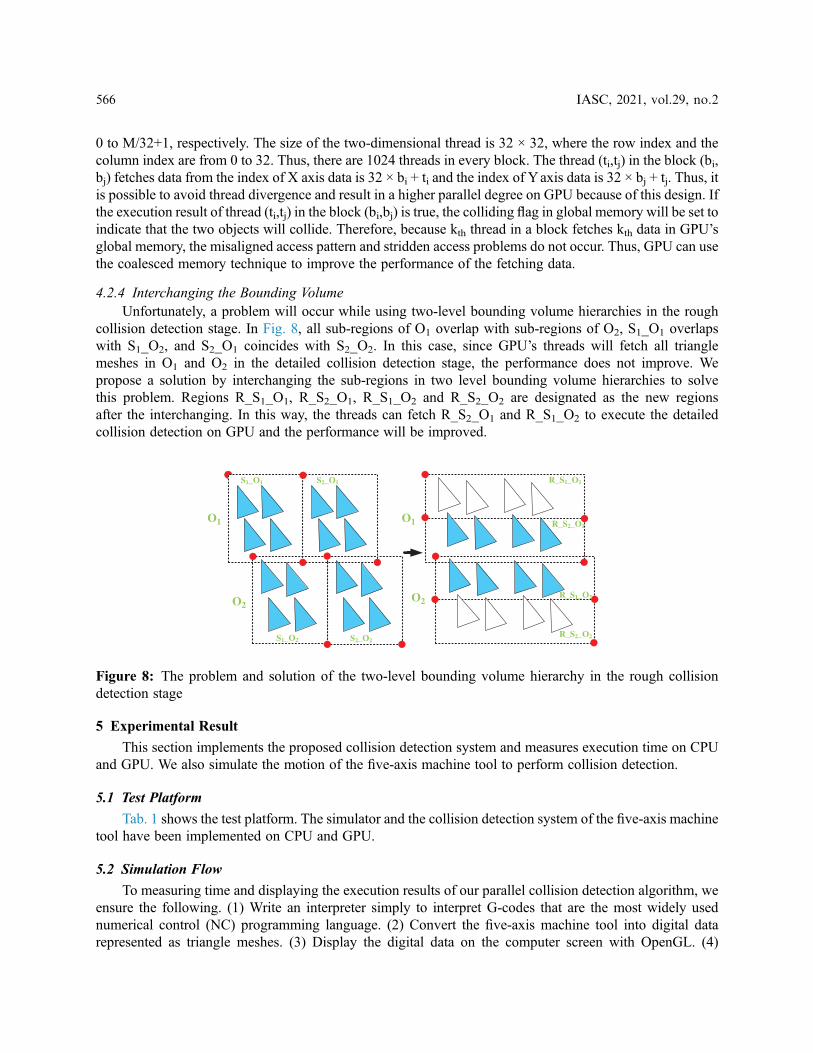
4.2.4 Interchanging the Bounding VolumeUnfortunately, a problem will occur while using two-level bounding volume hierarchies in the rough
collision detection stage. In Fig. 8, all sub-regions of O1 overlap with sub-regions of O2, S1_O1 overlapswith S1_O2, and S2_O1 coincides with S2_O2. In this case, since GPU’s threads will fetch all trianglemeshes in O1 and O2 in the detailed collision detection stage, the performance does not improve. Wepropose a solution by interchanging the sub-regions in two level bounding volume hierarchies to solvethis problem. Regions R_S1_O1, R_S2_O1, R_S1_O2 and R_S2_O2 are designated as the new regionsafter the interchanging. In this way, the threads can fetch R_S2_O1 and R_S1_O2 to execute the detailedcollision detection on GPU and the performance will be improved.
5 Experimental Result
This section implements the proposed collision detection system and measures execution time on CPUand GPU. We also simulate the motion of the five-axis machine tool to perform collision detection.
5.1 Test Platform
Tab. 1 shows the test platform. The simulator and the collision detection system of the five-axis machinetool have been implemented on CPU and GPU.
5.2 Simulation Flow
To measuring time and displaying the execution results of our parallel collision detection algorithm, weensure the following. (1) Write an interpreter simply to interpret G-codes that are the most widely usednumerical control (NC) programming language. (2) Convert the five-axis machine tool into digital datarepresented as triangle meshes. (3) Display the digital data on the computer screen with OpenGL. (4)
O1
O2
S1_O1 S2_O1
S1_O2 S2_O2
R_S1_O1
R_S2_O1
R_S1_O2
R_S2_O2
O1
O2
Figure 8: The problem and solution of the two-level bounding volume hierarchy in the rough collisiondetection stage
566 IASC, 2021, vol.29, no.2

Write motion control simply with the sample time = 0.1 ms and the federate = 10000 mm/min. (5) Simulatethe motion of the five-axis machine tool. For example, if the cutter moves a unit toward the X direction, thefive-axis machine tool must move the X axis first and then move Z axis. (6) Perform the collision detectionfor the eight cases: Cutter-X, Cutter-Y, Cutter-A, Cutter-C, Z-X, Z-Y, Z-A and Z-C.
In Fig. 9, we can begin to simulate the five-axis machine tool’s motion in the computer. When the cuttermoves a minimum unit, the program performs the collision detection for the eight cases above. If the twoobjects collide, the program stops running.
5.3 Performance Evaluation
We measure the execution time of the eight cases mentioned above on GPU and CPU. The executiontime on GPU is the CUDA profiling tools. The numbers of triangle meshes of X, Y, and Z axes are44,136, and 180. The numbers of triangle meshes of A, C, and the cutter are 164, 548, and 716. Theexecution time for CPU and GPU are shown in Tabs. 2 and 3. From the result, we can see that theCutter-C case takes more execution time than the others because there are more numbers of triangle
Table 1: Test platform
CPU type Inter Xeon CPU E5-2620
CPU clock 2.0 GHz
Host memory 16 GB
GPU type Tesla K20c
GPU clock 2600 MHz
Device memory 5 GB
CUDA capability 3.5
CUDA driver CUDA 5.0
Operating system CentOS release 6.4
Host compiler Gcc (GCC) 4.4.7
Device compiler Nvcc 5.0
Figure 9: The five-axis CNC machine tool and its simulator
IASC, 2021, vol.29, no.2 567

meshes. Moreover, using our parallel method on GPU, the proposed work can improve the performance by37.1 times compared to CPU in terms of average execution time.
6 Conclusion
We have presented an efficient method for axial table collision detection on five-axis machining in thispaper. Our approach includes analyzing machine kinematics and interpolating for separating axes that get ridof complicated cross-product computation. The performance result shows that the proposed approach is veryefficient with GPU compared with the conventional detection method. Besides, there is usually a tinyembedded system in machine tools. Our parallel method on GPU is workable. Therefore, the performanceof our parallel method is adjustable based on the limitation of a real-time system.
Acknowledgement: The authors would like to acknowledge the financial support of the National ScienceCouncil, Taiwan, ROC under the grant of project MOST 108-2218-E-194-007.
Funding Statement: The authors received no specific funding for this study.
Conflicts of Interest: The authors declare that they have no conflicts of interest to report regarding thepresent study.
Table 2: Execution time on CPU (us)
AVG MIN MAX
Z-Y 8323.44 4949.18 18169.06
Z-A 12729.96 6721.09 24505.73
Z-C 39336 13095.01 48574
Z-X 11198.24 6105.13 22214.41
Cutter-A 31290 15576.16 40528
Cutter-C 89698 39336 108174
Cutter-Y 22895.64 19203.72 33078
Cutter-X 14562.96 9691.56 23376.91
Table 3: Execution time on CPU (us) and speedup of average execution time compared to CPU
AVG MIN MAX Speedup
Z-Y 256.29 140.12 537.57 32.47
Z-A 306.24 199.27 695.53 41.56
Z-C 1082 388.16 1407.63 36.35
Z-X 327.54 179.68 688.24 34.18
Cutter-A 762.17 508.21 1165.77 41.05
Cutter-C 2260.53 1287.31 3108.75 39.68
Cutter-Y 648.92 498.83 986.98 35.28
Cutter-X 401.46 302.69 781.43 36.27
568 IASC, 2021, vol.29, no.2

References[1] S. Gottschalk, M. C. Lin and D. Manocha, “OBBTree: A hierarchical structure for rapid interference detection,” in
Proc. SIGGRAPH, New York, NY, USA, pp. 171–180, 1996.
[2] J. Huynh, “Separating axis theorem for oriented bounding boxes,” Beersheva, Israel: Ben-Gurion University ofthe Negev, 2009. [Online]. Available: https://www.cs.bgu.ac.il/~vgp182/wiki.files/Separating%20Axis%20Theorem%20for%20Oriented%20Bounding%20Boxes.pdf.
[3] T. Möller, “A fast triangle-triangle intersection test,” Journal of Graphics Tools, vol. 2, no. 2, pp. 25–30, 1997.
[4] M. Held, “ERIT–A collection of efficient and reliable intersection tests,” Journal of Graphics Tools, vol. 2, no. 4,pp. 25–44, 1997.
[5] G. Philippe and O. Devillers, “Fast and robust triangle-triangle overlap test using orientation predicates,” Journalof Graphics Tools, vol. 8, no. 1, pp. 25–32, 2003.
[6] O. Tropp, A. Tal and I. Shimshoni, “A fast triangle to triangle intersection test for collision detection,” ComputerAnimation and Virtual Worlds, vol. 17, no. 5, pp. 527–535, 2006.
[7] J. W. Chang and M. S. Kim, “Efficient triangle-triangle intersection test for OBB-based collision detection,”Computers & Graphics, vol. 33, no. 3, pp. 235–240, 2009.
[8] J. Ritter, An efficient bounding sphere. Santa Clara, CA, USA: Academic Press Professional, 1990. [Online].Available: https://www.researchgate.net/profile/Jack_Ritter/publication/242453691_An_Efficient_Bounding_Sphere/links/56e9d24e08ae95bddc2a2358/An-Efficient-Bounding-Sphere.
[9] J. D. Cohen, M. Lin, D. Manocha and M. K. Ponamgi, “I-collide: An interactive and exact collision detectionsystem for large-scale environments,” in Proc. I3D, New York, NY, USA, pp. 189-ff, 1995.
[10] S. Gottschalk, “Collision queries using oriented bounding boxes,” Ph.D. dissertation. University of NorthCarolina at Chapel Hill, USA, 2000.
[11] J. T. Klosowski, M. Held, J. S. B. Mitchell, H. Sowizral and K. Zikan, “Efficient collision detection usingbounding volume hierarchies of k-DOPs,” IEEE transactions on Visualization and Computer Graphics, vol. 4,no. 1, pp. 21–36, 1998.
[12] B. Chazelle, “An optimal convex hull algorithm in any fixed dimension,” Discrete & Computational Geometry,vol. 10, no. 4, pp. 337–409, 1993.
[13] J. Cheng, M. Grossman and T. McKercher, Professional CUDA C programming. Hoboken, NJ, USA:John Wiley & Sons, 2014 [Online]. Available: https://books.google.com.tw/books?hl=zh-TW&lr=&id=q3DvBQAAQBAJ&oi=fnd&pg=PR17&dq=NVIDIA+CUDA+C+Programming+Guide&ots=Kil1-mqyJ-&sig=TAhBbhb774M6HgS-uIhVuVPPxKM&redir_esc=y#v=onepage&q=NVIDIA%20CUDA%20C%20Programming%20Guide&f=false.
[14] V. A. Dudnik, V. I. Kudryavtsev, S. A. Us and M. V. Shestakov, “Advanced features of NVIDIA Keplerarchitecture and parallel computation platform CUDA for developing scientific compute-intensiveapplications,” Problems of Atomic Science and Technology, vol. 71, no. 121, pp. 105–108, 2019.
IASC, 2021, vol.29, no.2 569