Embed Size (px)
Citation preview

This article was downloaded by: [Iowa State University]On: 01 October 2014, At: 03:55Publisher: Taylor & FrancisInforma Ltd Registered in England and Wales Registered Number: 1072954 Registeredoffice: Mortimer House, 37-41 Mortimer Street, London W1T 3JH, UK
Electric Power Components and SystemsPublication details, including instructions for authors andsubscription information:http://www.tandfonline.com/loi/uemp20
Parameter Identification of Wind Turbinefor Maximum Power-point TrackingControlAbdul Motin Howlader a , Naomitsu Urasaki a , Kousuke Uchida a ,Atsushi Yona a , Tomonobu Senjyu a , Chul-Hwan Kim b & A. Y. Saber ca Department of Electrical and Electronics Engineering , Universityof the Ryukyus , Okinawa, Japanb Department of Electrical and Electronics Engineering ,Sungkyunkwan University , Koreac Department of Electrical and Computer Engineering , MissouriUniversity of Science and Technology , Rolla, Missouri, USAPublished online: 22 Mar 2010.
To cite this article: Abdul Motin Howlader , Naomitsu Urasaki , Kousuke Uchida , Atsushi Yona ,Tomonobu Senjyu , Chul-Hwan Kim & A. Y. Saber (2010) Parameter Identification of Wind Turbine forMaximum Power-point Tracking Control, Electric Power Components and Systems, 38:5, 603-614, DOI:10.1080/15325000903376974
To link to this article: http://dx.doi.org/10.1080/15325000903376974
PLEASE SCROLL DOWN FOR ARTICLE
Taylor & Francis makes every effort to ensure the accuracy of all the information (the“Content”) contained in the publications on our platform. However, Taylor & Francis,our agents, and our licensors make no representations or warranties whatsoever as tothe accuracy, completeness, or suitability for any purpose of the Content. Any opinionsand views expressed in this publication are the opinions and views of the authors,and are not the views of or endorsed by Taylor & Francis. The accuracy of the Contentshould not be relied upon and should be independently verified with primary sourcesof information. Taylor and Francis shall not be liable for any losses, actions, claims,proceedings, demands, costs, expenses, damages, and other liabilities whatsoever orhowsoever caused arising directly or indirectly in connection with, in relation to or arisingout of the use of the Content.
This article may be used for research, teaching, and private study purposes. Anysubstantial or systematic reproduction, redistribution, reselling, loan, sub-licensing,systematic supply, or distribution in any form to anyone is expressly forbidden. Terms &

Conditions of access and use can be found at http://www.tandfonline.com/page/terms-and-conditions
Dow
nloa
ded
by [
Iow
a St
ate
Uni
vers
ity]
at 0
3:55
01
Oct
ober
201
4
Electric Power Components and Systems, 38:603–614, 2010
Copyright © Taylor & Francis Group, LLC
ISSN: 1532-5008 print/1532-5016 online
DOI: 10.1080/15325000903376974
Parameter Identification of Wind Turbine
for Maximum Power-point Tracking Control
ABDUL MOTIN HOWLADER,1 NAOMITSU URASAKI,1
KOUSUKE UCHIDA,1 ATSUSHI YONA,1
TOMONOBU SENJYU,1 CHUL-HWAN KIM,2 and
A. Y. SABER3
1Department of Electrical and Electronics Engineering, University of the
Ryukyus, Okinawa, Japan2Department of Electrical and Electronics Engineering, Sungkyunkwan
University, Korea3Department of Electrical and Computer Engineering, Missouri University
of Science and Technology, Rolla, Missouri, USA
Abstract In this article, a technique is proposed for maximum power-point trackingcontrol of a wind generation system. The optimal operation speed to which the
wind turbine output power maximizes is determined with parameters identified byan iterative least squares technique. The effectiveness of the maximum point tracking
control with identified parameters of wind turbine is verified by computer simulation.In addition, the article discusses how to address rotational speed and output power
in the case when the wind turbine parameters used for determining the optimumrotational speed have errors.
Keywords wind turbine generation system, maximum power-point tracking, onlineparameter identification
1. Introduction
Electric power generation using non-conventional sources is receiving considerable at-
tention throughout the world. Wind energy is a significant and powerful resource. It
is safe, clean, and abundant. Unlike conventional fuels, wind energy is a massive in-
digenous power source permanently available in virtually every nation in the world. It
delivers energy security benefits by avoiding fuel costs, long-term fuel price risk, and
the economic and supply risks that come with reliance on imported fuels and political
dependence on other countries [1]. However, wind energy has a drawback of having
only 1/800 density and irregularity as compared to that of water energy. How it can
be utilized as a highly efficient electric power energy source is important. Because
Received 17 February 2009; accepted 30 September 2009.Address correspondence to Mr. Abdul Motin Howlader, Department of Electrical and
Electronics Engineering, University of the Ryukyus, 1 Senbaru, Nishihara-cho, Okinawa, 903-0213,Japan. E-mail: [email protected]
603
Dow
nloa
ded
by [
Iow
a St
ate
Uni
vers
ity]
at 0
3:55
01
Oct
ober
201
4
604 A. M. Howlader et al.
of this problem, various high-efficiency control schemes have been reported in recent
years [2–5].
In the wind turbine generation system, the squirrel-cage induction generator (IG) is
introduced because it is robust and has low cost. Power generation using wind energy
is possible in two ways, viz., constant-speed operation and variable-speed operation
using power electronic converters. Variable-speed power generation for a wind turbine
is attractive, because maximum efficiency can be achieved at all wind velocities. Some
works proposed determining the optimum operating speed based on the hill-climbing
method [6, 7]. However, the hill-climbing method takes a long time to arrive at a solution
and is, therefore, disadvantageous for maximum power-point tracking. The optimal wind
turbine rotor speed method obtains the maximum power point swiftly. The parameters
of the optimal wind turbine rotor speed method are sensitive. In case of the chage
in parameters, the output power is affected significantly. In this article, a technique is
proposed to identify the parameters of the wind turbine. Moreover, a wind power system
has to operate at the maximum power point by using the above-identified wind turbine
parameters to optimize operation speed. The rest of the article is organized as follows.
The modeling of the wind generation system is presented in Section 2. The optimization
of operating points is presented in Section 3. Section 4 shows how to control the IG. The
wind turbine parameter identification method is presented in Section 5. The proposed
method has been tested by simulation as described in Section 6, and Section 7 provides
the conclusion.
2. Wind Turbine Generation System
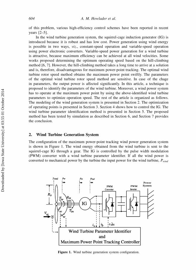
The configuration of the maximum power-point tracking wind power generation system
is shown in Figure 1. The wind energy obtained from the wind turbine is sent to the
squirrel-cage IG through a gear. The IG is controlled by the pulse width modulation
(PWM) converter with a wind turbine parameter identifier. If all the wind power is
converted to mechanical power by the turbine the input power for the wind turbine, Pwind
Figure 1. Wind turbine generation system configuration.
Dow
nloa
ded
by [
Iow
a St
ate
Uni
vers
ity]
at 0
3:55
01
Oct
ober
201
4
Parameter Identification of Wind Turbine Generation System 605
is expressed as
Pwind D1
2��R2
oV 3w ; (1)
where Ro is wind turbine blade radius, � is the air density, and Vw is the wind speed.
The wind turbine input torque Twind can be described as
Twind D�
!w
Pwind;
D1
2��R3
oV 2w ; (2)
where !w is the rotor speed of the wind turbine, and � is the tip speed ratio, which
can be defined as � D Ro!w
Vw. The wind turbine converts wind power into mechanical
power Pw:
Pw D1
2��R2
oV 3wCp: (3)
The power coefficient Cp is defined as Cp D ��3 C ��2 C �, where � , �, and are
coefficients that are determined by size, form of blade, number of blades, and pitch angle
of the wind tubine blade. Wind turbine output torque is defined by
Tw D1
2��R3
oV2
wCt ; (4)
where Ct is the torque coefficient, defined as Ct DCp
�. The wind turbine loss torque Tf
serves as a convex function according to wind velocity and the angular velocity of wind
turbine; it can be expressed as an approximation equation [4]
Tf D Twind � Tw ;
D K0V 2w C K1Vw!w C K2!2
w: (5)
Here, the wind turbine loss coefficients K0, K1, and K2 are expressed as
K0 D1
2�SRo.1 � /; (6)
K1 D �1
2�SR2
o�; (7)
K2 D �1
2�SR3
o�; (8)
where S is the blade rotation area. The motion equation of the wind turbine output torque
that can actually be extracted from a wind turbine can be expressed as
Tw D Jw
d!w
dtC Tlw ; (9)
where J! is the wind turbine inertia, and Tlw is the load torque. The relationship of
the rotor speed and torque between the wind turbine and the generator is expressed
Dow
nloa
ded
by [
Iow
a St
ate
Uni
vers
ity]
at 0
3:55
01
Oct
ober
201
4
606 A. M. Howlader et al.
as the following equations by using the gear ratio Rn:
!m D Rn!w ; (10)
Tlm D �1
Rn
Tlw ; (11)
where !m is the generator rotor speed, and Tlm is the generator input torque. Input power
to the generator Pin is expressed as
Pin D �Tlm!m: (12)
The motion equation of the generator is expressed as
Jm
d!m
dtC Dm!m C Tlm D Tm; (13)
where Jm is the generator inertia, Dm is the damping coefficient, and Tm is the generator
electric torque. The output power of generator Pout is expressed as
Pout D Tm!m: (14)
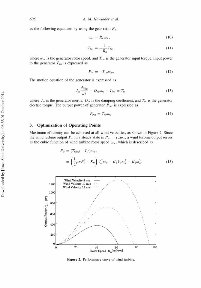
3. Optimization of Operating Points
Maximum efficiency can be achieved at all wind velocities, as shown in Figure 2. Since
the wind turbine output Pw in a steady state is Pw D Tw!w , a wind turbine output serves
as the cubic function of wind turbine rotor speed !w, which is described as
Pw D .Twind � Tf /!w ;
D
�1
2��R3
o � K0
�V 2
! !w � K1V!!2w � K2!3
w: (15)
Figure 2. Performance curve of wind turbine.
Dow
nloa
ded
by [
Iow
a St
ate
Uni
vers
ity]
at 0
3:55
01
Oct
ober
201
4
Parameter Identification of Wind Turbine Generation System 607
The optimal wind turbine rotor speed !optw is obtained as the local maxima of the following
equation due to dPw=d!w D 0 [8]:
dP!
d!w
D
�1
2��R3
o � K0
�V 2
! � 2K1V!!w � 3K2!2w D 0; (16)
!optw D
�K1Vw C
s.K1Vw/2 � 3K2
�1
2��R3
o � K0
�V 2
w
3K2
: (17)
4. Parameter Identification
In this article, the parameter identification method deals with the wind turbine loss
coefficients K0, K1, and K2. Here is proposed least squares off-line technique based
on N units of the data to identify parameters. To implement identification the algorithm
in recursive form, the parameters estimate are updated when new data points become
available [9].
The system equation is
Tw.N / D zTN K N C e.N /; (18)
where zTN is the regressions vector that contains input–output data, KN is the wind
turbine parameters, and e.N / is the white noise. The zTN is given by
zTN � ŒTwind.N � 1/; Twind.N � 2/; : : : ; Twind.N � n/;
Tw.N /; Tw.N � 1/; : : : ; Tw.N � n/�: (19)
The wind turbine parameter is constant, expressed by K NC1 D K N : The white noise
e.N / is defined by
Efe.N /g D 0; (20)
where E denotes the exceptation of operator. The calculation of identification is ex-
pressed by
bK N D bK N�1 C C N .Tw.N / � zTN
bK N�1/; (21)
where C N is given by
C N D PN�1zN .1 C PN�1z2N /�1; (22)
and the factor .Tw.N / � zTN
bKN�1/ is the prediction error. To update P ,
PN D PN�1 � P2N�1z
2N .1 C z
TN PN�1zN /�1 : (23)
Initially, PN is a large positive number. The initial value of zN is expressed by
z1 � ŒTwind.0/; Twind.�1/; : : : ; Twind.1 � N /; Tw.1/; Tw.0/; : : : ; Tw.1 � n/�T : (24)
Dow
nloa
ded
by [
Iow
a St
ate
Uni
vers
ity]
at 0
3:55
01
Oct
ober
201
4
608 A. M. Howlader et al.
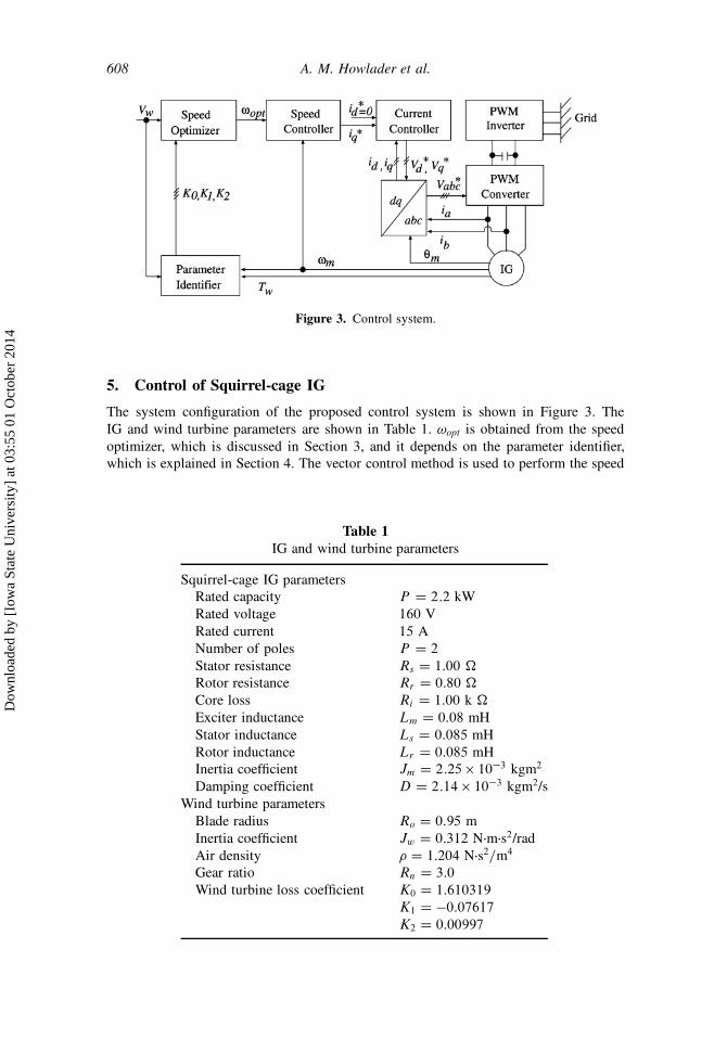
Figure 3. Control system.
5. Control of Squirrel-cage IG
The system configuration of the proposed control system is shown in Figure 3. The
IG and wind turbine parameters are shown in Table 1. !opt is obtained from the speed
optimizer, which is discussed in Section 3, and it depends on the parameter identifier,
which is explained in Section 4. The vector control method is used to perform the speed
Table 1
IG and wind turbine parameters
Squirrel-cage IG parameters
Rated capacity P D 2:2 kW
Rated voltage 160 V
Rated current 15 A
Number of poles P D 2
Stator resistance Rs D 1:00 �
Rotor resistance Rr D 0:80 �
Core loss Ri D 1:00 k �
Exciter inductance Lm D 0:08 mH
Stator inductance Ls D 0:085 mH
Rotor inductance Lr D 0:085 mH
Inertia coefficient Jm D 2:25 � 10�3 kgm2
Damping coefficient D D 2:14 � 10�3 kgm2/s
Wind turbine parameters
Blade radius Ro D 0:95 m
Inertia coefficient Jw D 0:312 N�m�s2/rad
Air density � D 1:204 N�s2=m4
Gear ratio Rn D 3:0
Wind turbine loss coefficient K0 D 1:610319
K1 D �0:07617
K2 D 0:00997
Dow
nloa
ded
by [
Iow
a St
ate
Uni
vers
ity]
at 0
3:55
01
Oct
ober
201
4
Parameter Identification of Wind Turbine Generation System 609
control of the IG. The torque current reference value is given as
i�
qs D1
KT
�Jm
d!�m
dtC D!�
m C bTlm C kP!e! C kI!
Ze!dt
�; (25)
where bTlm is the estimated input torque of the generator, kP! is the propotional gain for
the speed controller, kI! is the integral gain for the speed controller, and the speed error
is e! D !�m � !m. In addition, the generator may minimize the electric power loss by
executing the motor operation for tracking to the reference value, and an over-current
may occur for motor operation. Hence, a restriction of �20 � i�qs � 0A is adapted in
the q-axis current reference value i�qs . Furthermore, the d -q-axis reference voltages are
determined by the following equations by a proportional-integral (PI) controller using
the current reference value [10]:
v�
ds D kP ieid C kI i
Zeid dt; (26)
v�
qs D kP ieiq C kI i
Zeiqdt; (27)
where kP i is the proportional gain for the current controller, kI i is integral gain for the
current controller, eid D i�
ds � ids is the d -axis current error, and eiq D i�
qs � iqs is
the q-axis current error.
6. Simulation Results
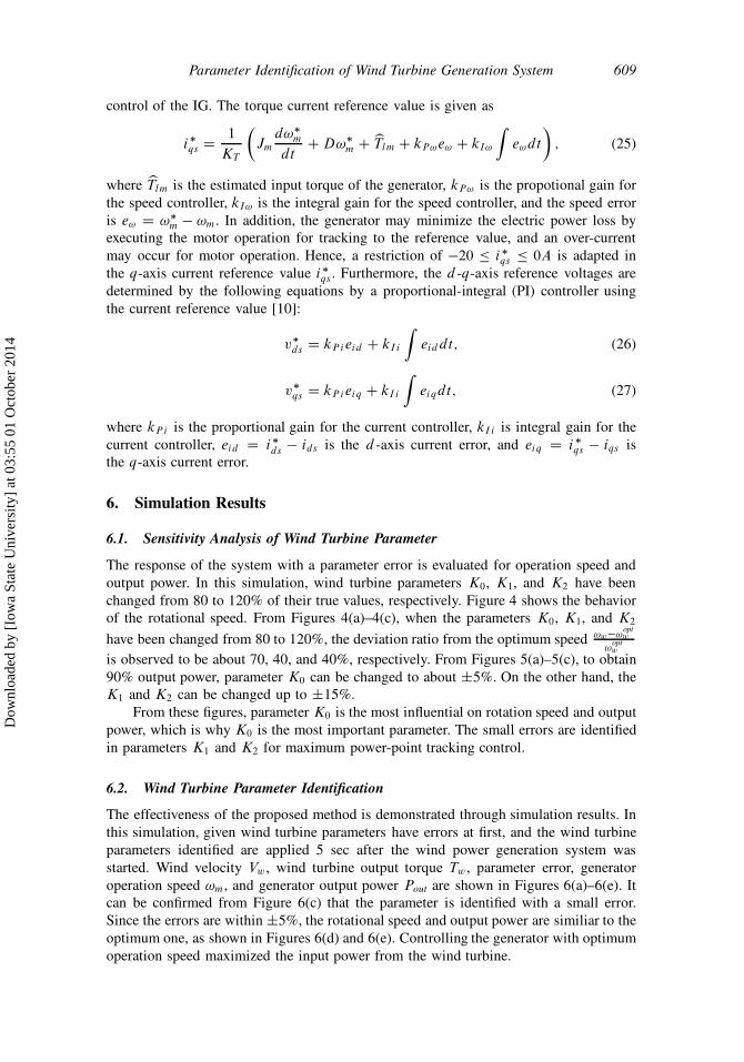
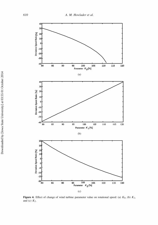
6.1. Sensitivity Analysis of Wind Turbine Parameter
The response of the system with a parameter error is evaluated for operation speed and
output power. In this simulation, wind turbine parameters K0, K1, and K2 have been
changed from 80 to 120% of their true values, respectively. Figure 4 shows the behavior
of the rotational speed. From Figures 4(a)–4(c), when the parameters K0, K1, and K2
have been changed from 80 to 120%, the deviation ratio from the optimum speed !w�!optw
!optw
is observed to be about 70, 40, and 40%, respectively. From Figures 5(a)–5(c), to obtain
90% output power, parameter K0 can be changed to about ˙5%. On the other hand, the
K1 and K2 can be changed up to ˙15%.
From these figures, parameter K0 is the most influential on rotation speed and output
power, which is why K0 is the most important parameter. The small errors are identified
in parameters K1 and K2 for maximum power-point tracking control.
6.2. Wind Turbine Parameter Identification
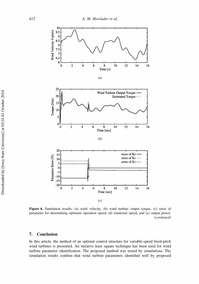
The effectiveness of the proposed method is demonstrated through simulation results. In
this simulation, given wind turbine parameters have errors at first, and the wind turbine
parameters identified are applied 5 sec after the wind power generation system was
started. Wind velocity Vw , wind turbine output torque Tw , parameter error, generator
operation speed !m, and generator output power Pout are shown in Figures 6(a)–6(e). It
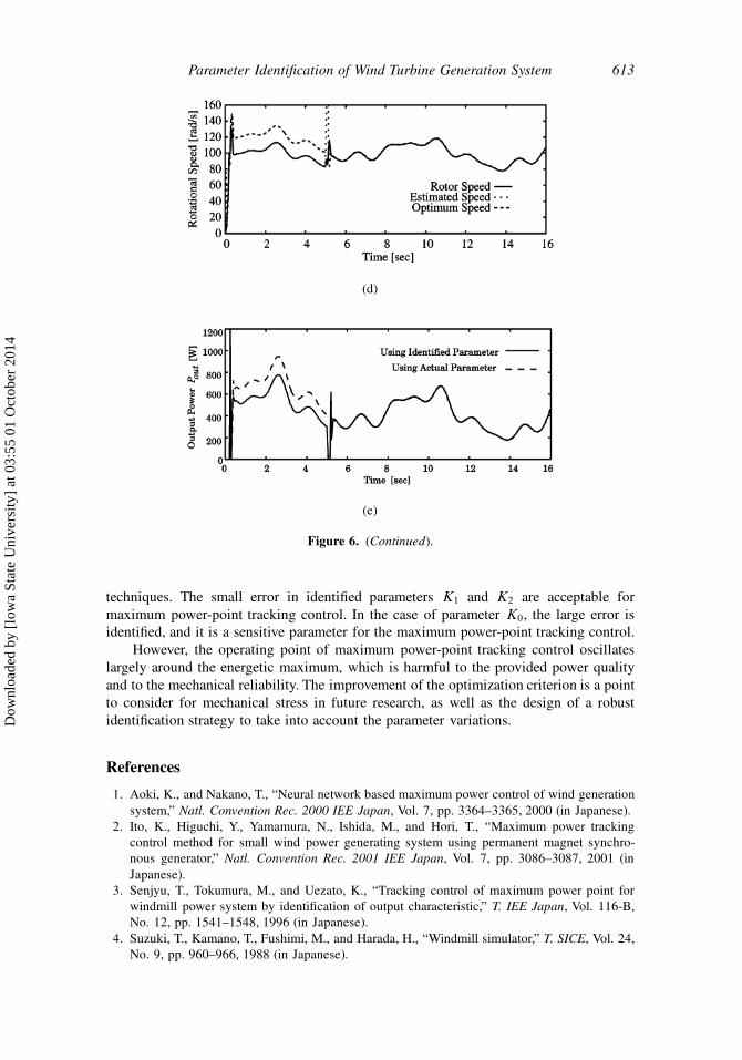
can be confirmed from Figure 6(c) that the parameter is identified with a small error.
Since the errors are within ˙5%, the rotational speed and output power are similiar to the
optimum one, as shown in Figures 6(d) and 6(e). Controlling the generator with optimum
operation speed maximized the input power from the wind turbine.
Dow
nloa
ded
by [
Iow
a St
ate
Uni
vers
ity]
at 0
3:55
01
Oct
ober
201
4
610 A. M. Howlader et al.
(a)
(b)
(c)
Figure 4. Effect of change of wind turbine parameter value on rotational speed: (a) K0, (b) K1,
and (c) K2.
Dow
nloa
ded
by [
Iow
a St
ate
Uni
vers
ity]
at 0
3:55
01
Oct
ober
201
4
Parameter Identification of Wind Turbine Generation System 611
(a)
(b)
(c)
Figure 5. Effect of change of wind turbine parameter value on output power: (a) K0, (b) K1, and
(c) K2.
Dow
nloa
ded
by [
Iow
a St
ate
Uni
vers
ity]
at 0
3:55
01
Oct
ober
201
4
612 A. M. Howlader et al.
(a)
(b)
(c)
Figure 6. Simulation results: (a) wind velocity, (b) wind turbine output torque, (c) error of
parameter for determining optimum operation speed, (d) rotational speed, and (e) output power.
(continued)
7. Conclusion
In this article, the method of an optimal control structure for variable-speed fixed-pitch
wind turbines is presented. An iterative least square technique has been used for wind
turbine parameter identification. The proposed method was tested by simulations. The
simulation results confirm that wind turbine parameters identified well by proposed
Dow
nloa
ded
by [
Iow
a St
ate
Uni
vers
ity]
at 0
3:55
01
Oct
ober
201
4
Parameter Identification of Wind Turbine Generation System 613
(d)
(e)
Figure 6. (Continued).
techniques. The small error in identified parameters K1 and K2 are acceptable for
maximum power-point tracking control. In the case of parameter K0, the large error is
identified, and it is a sensitive parameter for the maximum power-point tracking control.
However, the operating point of maximum power-point tracking control oscillates
largely around the energetic maximum, which is harmful to the provided power quality
and to the mechanical reliability. The improvement of the optimization criterion is a point
to consider for mechanical stress in future research, as well as the design of a robust
identification strategy to take into account the parameter variations.
References
1. Aoki, K., and Nakano, T., “Neural network based maximum power control of wind generation
system,” Natl. Convention Rec. 2000 IEE Japan, Vol. 7, pp. 3364–3365, 2000 (in Japanese).
2. Ito, K., Higuchi, Y., Yamamura, N., Ishida, M., and Hori, T., “Maximum power tracking
control method for small wind power generating system using permanent magnet synchro-
nous generator,” Natl. Convention Rec. 2001 IEE Japan, Vol. 7, pp. 3086–3087, 2001 (in
Japanese).
3. Senjyu, T., Tokumura, M., and Uezato, K., “Tracking control of maximum power point for
windmill power system by identification of output characteristic,” T. IEE Japan, Vol. 116-B,
No. 12, pp. 1541–1548, 1996 (in Japanese).
4. Suzuki, T., Kamano, T., Fushimi, M., and Harada, H., “Windmill simulator,” T. SICE, Vol. 24,
No. 9, pp. 960–966, 1988 (in Japanese).
Dow
nloa
ded
by [
Iow
a St
ate
Uni
vers
ity]
at 0
3:55
01
Oct
ober
201
4

614 A. M. Howlader et al.
5. Chikaraishi, H., Hayashi, Y., and Sato, N., “A variable speed control of the induction generator
without speed sensor for wind generation,” T. IEE Japan, Vol. 110, pp. 664–672, 1990 (in
Japanese).
6. Tanaka, T., Toumiya, T., and Suzuki, T., “Output control by hill-climbing method for a small
scale wind power generating system,” Renew. Energy, Vol. 12, No. 4, pp. 387–400, 1997.
7. Arifujjaman, M., Tariq Iqbal, M., and Quaicoe, J. E., “Energy capture by a small wind-energy
conversion system,” Appl. Energy, Vol. 85, pp. 41–51, 2008.
8. Senjyu, T., Tamaki, S., Urasaki, N., Uezato, K., Funabashi, T., and Fujita, H., “Wind velocity
and position sensor-less operation for PMSG wind generator,” IEEJ Trans. PE, Vol. 123,
No. 12, pp. 1531–1537, 2003 (in Japanese).
9. Soderstrom, T., and Stoica, P., “Instrumental variable methods for system identification,”
Circuits Syst. Signal Process., Vol. 21, No. 1, pp. 1–9, 2002.
10. Levi, E., “Impact of iron loss on behavior of vector controlled induction machines,” IEEE
Trans. Industry Appl., Vol. 31, No. 6, pp. 171–178, 1995.
Dow
nloa
ded
by [
Iow
a St
ate
Uni
vers
ity]
at 0
3:55
01
Oct
ober
201
4