Embed Size (px)
DESCRIPTION
Parameters for various resonant switch networks. Salient features of small-signal transfer functions, for basic converters. Half-wave ZCS quasi-resonant buck Low frequency model: set tank elements to zero. Half-wave ZCS quasi-resonant boost Low frequency model: set tank elements to zero. - PowerPoint PPT Presentation
Citation preview
1
Parameters for various resonant switch networks
2
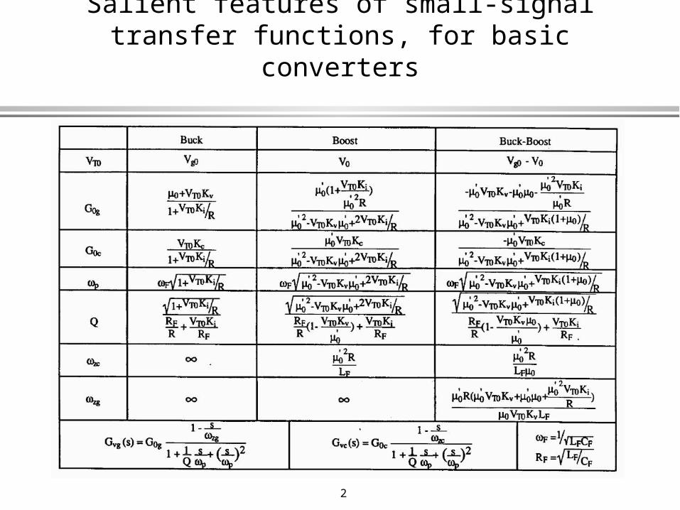
Salient features of small-signal transfer functions, for basic converters
3
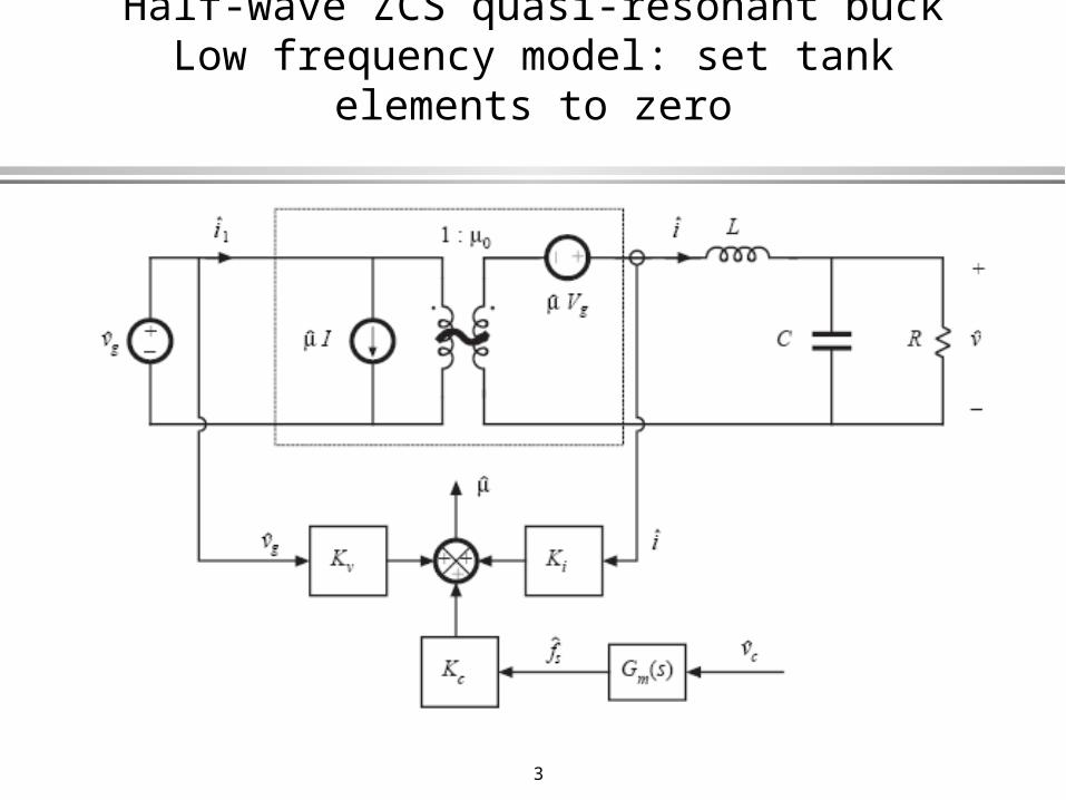
Half-wave ZCS quasi-resonant buckLow frequency model: set tank elements to zero
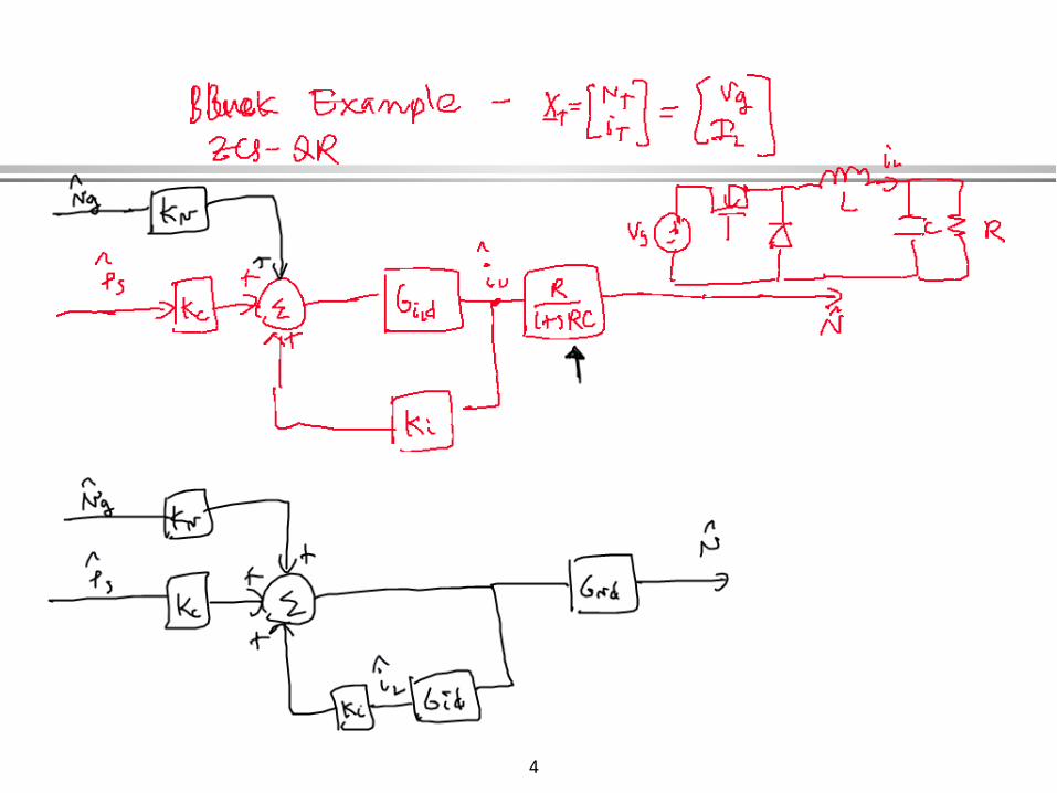
4

5

6
Half-wave ZCS quasi-resonant boostLow frequency model: set tank elements to zero

7

8
9
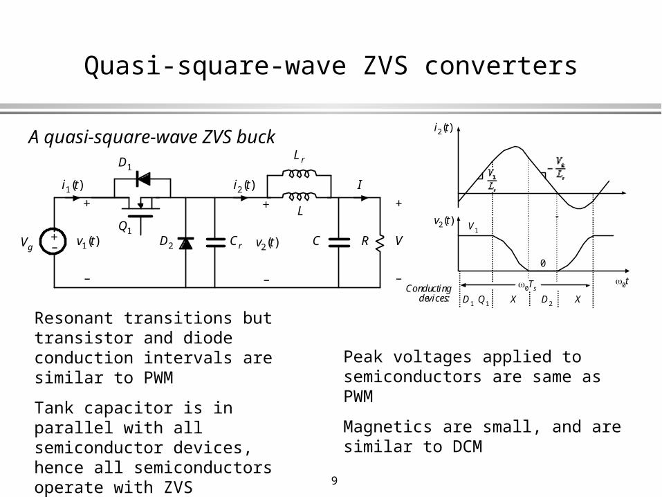
Quasi-square-wave ZVS converters
+– CrVg
D1
D2
Q1
+
v2(t)
–
i1(t) i2(t)
+
v1(t)
–
Lr
L
C R
+
V
–
I
0Ts
i2(t)
v2(t)V1
0t
0
Conductingdevices: D2X XQ1D1
A quasi-square-wave ZVS buck
Resonant transitions but transistor and diode conduction intervals are similar to PWM
Tank capacitor is in parallel with all semiconductor devices, hence all semiconductors operate with ZVS
Peak currents are increased, and are similar to DCM
Peak voltages applied to semiconductors are same as PWM
Magnetics are small, and are similar to DCM
10
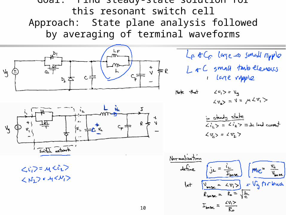
Goal: Find steady-state solution for this resonant switch cellApproach: State plane analysis followed by averaging of
terminal waveforms
11
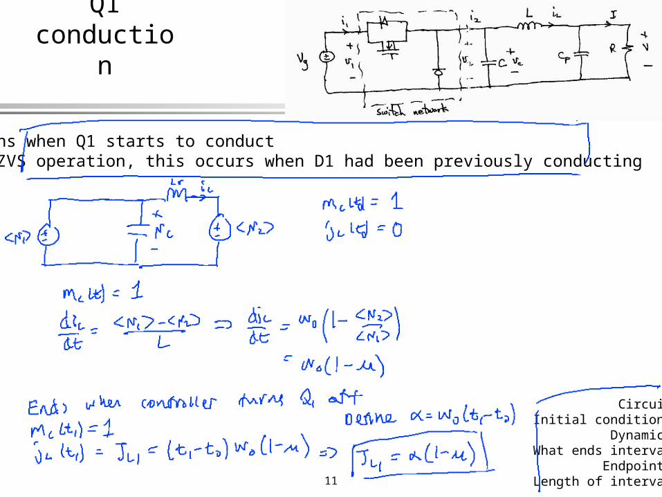
Interval 1Q1 conduction
Begins when Q1 starts to conductFor ZVS operation, this occurs when D1 had been previously conducting
CircuitInitial conditions
DynamicsWhat ends interval
EndpointsLength of interval
12
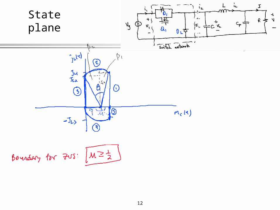
State plane
13
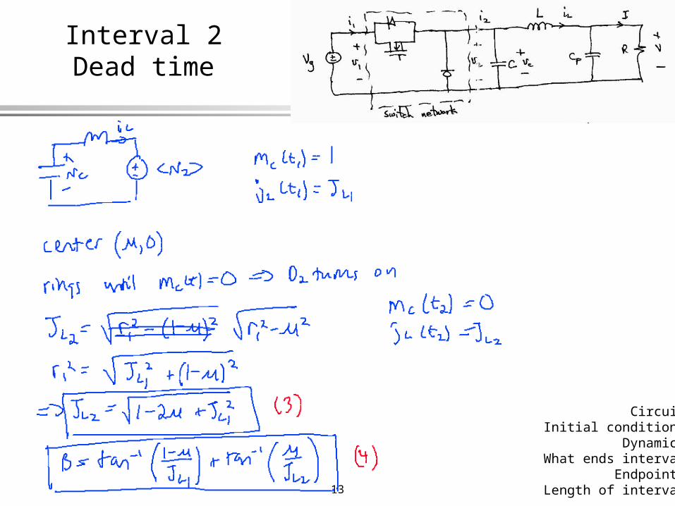
Interval 2Dead time
CircuitInitial conditions
DynamicsWhat ends interval
EndpointsLength of interval
14
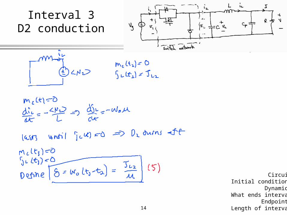
Interval 3D2 conduction
CircuitInitial conditions
DynamicsWhat ends interval
EndpointsLength of interval
15
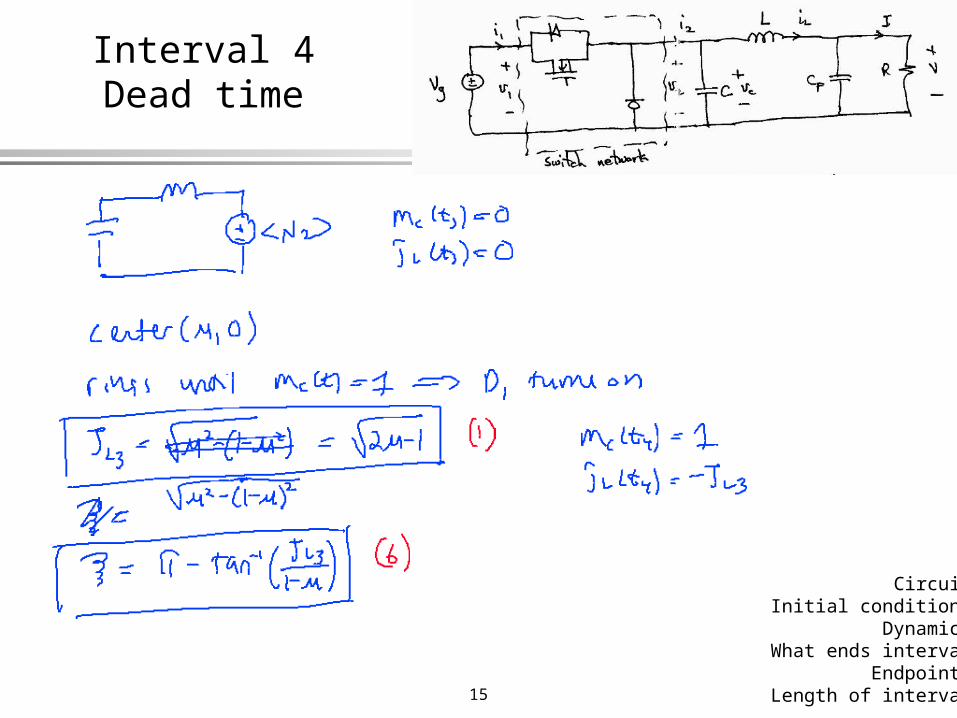
Interval 4Dead time
CircuitInitial conditions
DynamicsWhat ends interval
EndpointsLength of interval
16
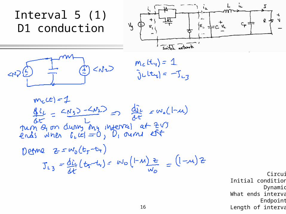
Interval 5 (1)D1 conduction
CircuitInitial conditions
DynamicsWhat ends interval
EndpointsLength of interval

17
Waveforms

18
Average switch input current
19
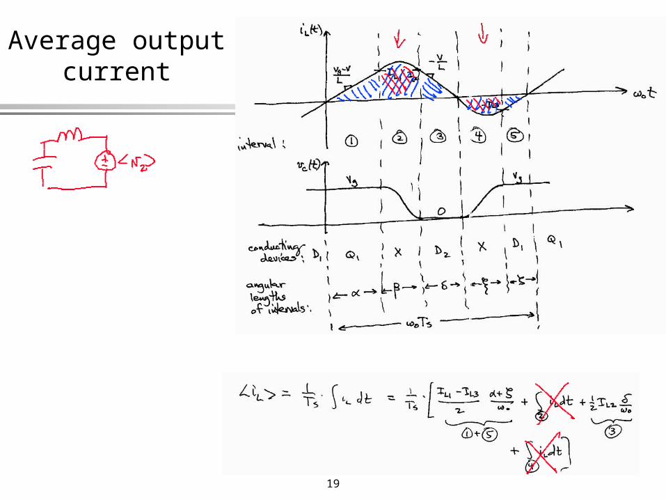
Average output current
20
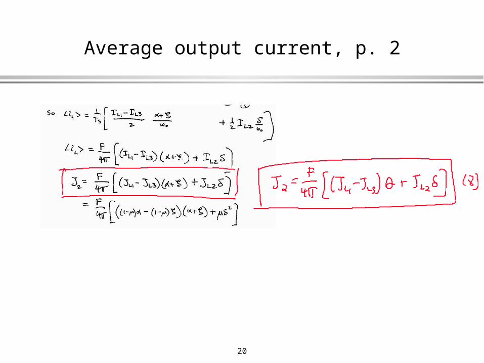
Average output current, p. 2
21
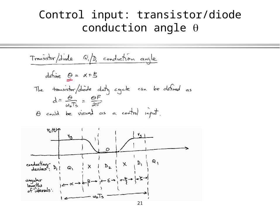
Control input: transistor/diode conduction angle

22
23
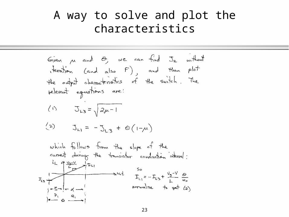
A way to solve and plot the characteristics
24
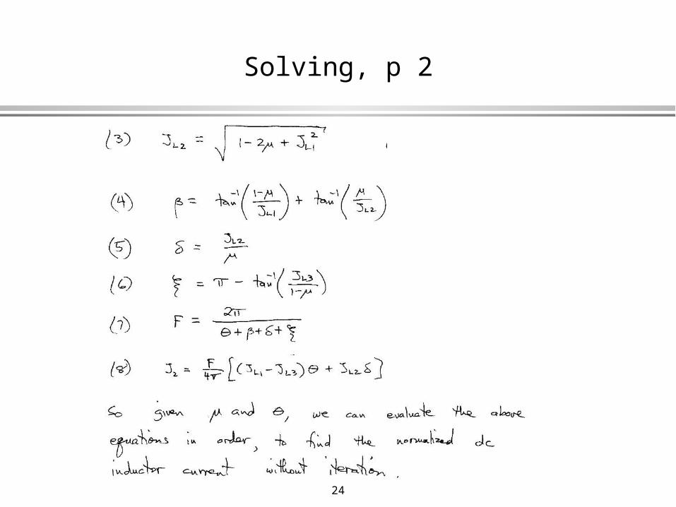
Solving, p 2
25
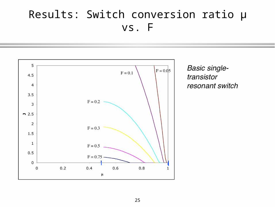
Results: Switch conversion ratio µ vs. F
26
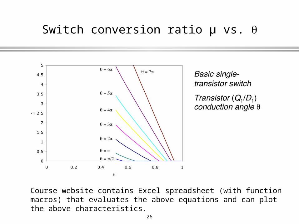
Switch conversion ratio µ vs.
Course website contains Excel spreadsheet (with function macros) that evaluates the above equations and can plot the above characteristics.
27
Soft-switching converters with constant switching frequency
With two or more active switches, we can obtain zero-voltage switching in converters operating at constant switching frequency
Often, the converter characteristics are nearly the same as their hard-switched PWM parent converters
The second switch may be one that is already in the PWM parent converter (synchronous rectifier, or part of a half or full bridge). Sometimes, it is not, and is a (hopefully small) auxiliary switch
Examples:• Two-switch quasi-square wave (with synchronous
rectifier)• Two-switch multiresonant (with synchronous rectifier)• Phase-shifted bridge with zero voltage transitions• Forward or other converter with active clamp circuit
These converters can exhibit stresses and characteristics that approach those of the parent hard-switched PWM converter (especially the last two), but with zero-voltage switching over a range of operating points

28
Quasi-square wave buck with two switches
• Q2 can be viewed as a synchronous rectifier
• Additional degree of control is possible: let Q2 conduct longer than D2 would otherwise conduct
• Constant switching frequency control is possible, with behavior similar to conventional PWM
• Can obtain µ < 0.5
• See Maksimovic PhD thesis, 1989
Original one-switch version
Add synchronous rectifier
29
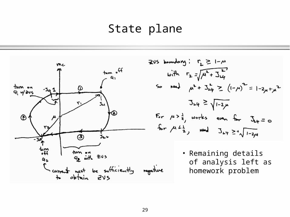
State plane
• Remaining details of analysis left as homework problem

30
Characteristics: 1 transistor version
µ vs. F
31
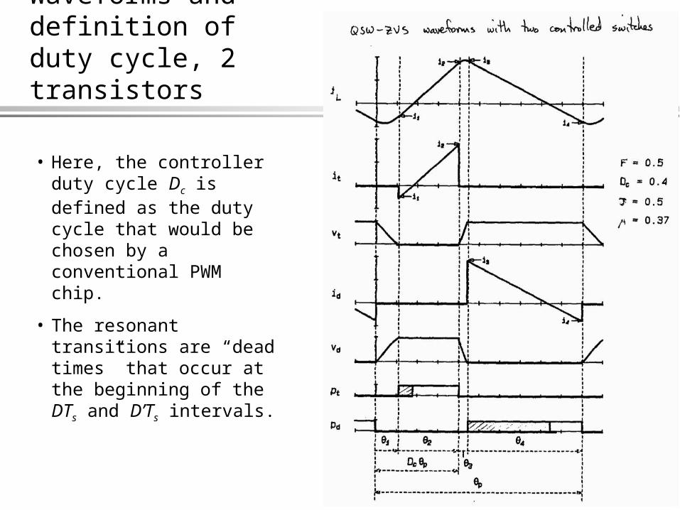
Waveforms and definition of duty cycle, 2 transistors
• Here, the controller duty cycle Dc is defined as the duty cycle that would be chosen by a conventional PWM chip.
• The resonant transitions are “dead times” that occur at the beginning of the DTs and D’Ts intervals.
32
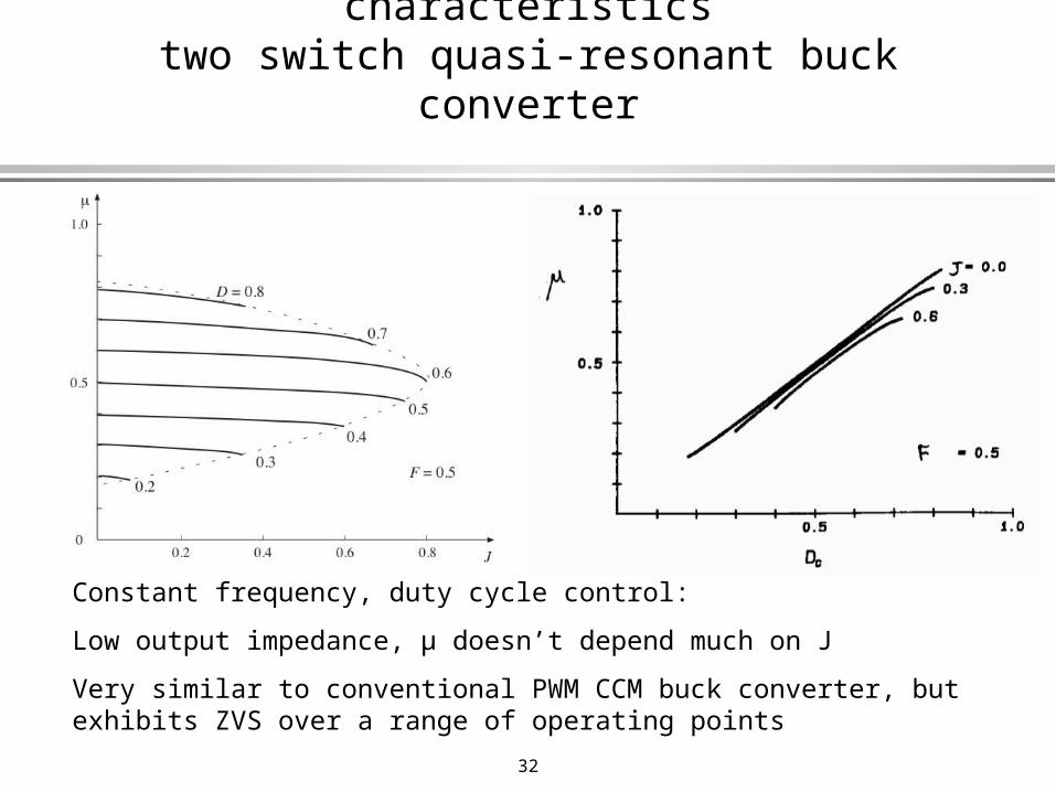
Constant-frequency control characteristicstwo switch quasi-resonant buck converter
Constant frequency, duty cycle control:
Low output impedance, µ doesn’t depend much on J
Very similar to conventional PWM CCM buck converter, but exhibits ZVS over a range of operating points
33
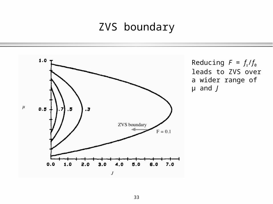
ZVS boundary
Reducing F = fs/f0 leads to ZVS over a wider range of µ and J


![Voltage mode control of soft-switched single switch ... · achieving ZVS and ZCS [28]. Quasi resonant converters [29] employ a single switch and provide soft switching condition without](https://img.pdfslide.net/doc/110x75/5e31277ee80634229e625f9c/voltage-mode-control-of-soft-switched-single-switch-achieving-zvs-and-zcs-28.jpg)