Embed Size (px)
Citation preview
PARAMETRIC DESIGN OF CONDUCTOR CROSS-ARMS FOR OHTL
LATTICE TOWERS
Model parametrisation in Tekla structures using Grasshopper
Bachelor’s thesis
Visamäki Campus, Degree Programme in Construction Engineering
Autumn 2019
Maxim Chistyakov
ABSTRACT Degree Programme in Construction Engineering Hämeenlinna University Centre Author Maxim Chistyakov Year 2019 Subject Parametric design of OHTL cross-arms for lattice towers Supervisor(s) Cristina Tirteu, Joonas Forsman ABSTRACT
The aim of this Bachelor’s thesis was to create a fully-functional parametric algorithm which automatically generates the model of a cross-arm structures for overhead transmission line (OHTL) lattice towers in Tekla Structures. The purpose of the thesis was to allow engineers to prevent any errors at the modelling stage. To build the parametric model Grasshopper by Rhino 6 was used. To prove the performance of the parametric algorithm, five tests were provided in Appendix 3. Each test has its own set of input parameters in order to enfold a majority of variations. The principle of verification is based on the creation of drawings along different views for each plane of the structure. As a result, the algorithm for cross-arm geometry including bolts and cuts was created. It was concluded that no direct modelling is needed for the cross-arm structures except connecting plates that are located between cross-arm and tower mainframe. Thus, the algorithm reduces the amount of time spent on the modelling phase and ensures error-free design.
Keywords Grasshopper, Lattice towers, Tekla structures, Parametric design Pages 16 pages including appendices 55 pages
CONTENTS
1 INTRODUCTION ........................................................................................................... 1
1.1 Background .......................................................................................................... 1
1.2 Aims and limitations ............................................................................................ 1
2 PRE-STUDY ................................................................................................................... 2
2.1 Explanation of a Parametric modelling ............................................................... 2
2.2 Introduction of Grasshopper ............................................................................... 3
2.3 The principle operation of Grasshopper ............................................................. 4
2.4 Integration with Tekla structures ........................................................................ 6
2.5 Power line towers ............................................................................................... 8
2.5.1 Design software ....................................................................................... 9
2.5.2 Types of transmission towers .................................................................. 9
2.5.3 Lattice self-supported towers ............................................................... 10
2.5.4 Cross-arm structures ............................................................................. 11
3 GOAL AND PURPOSE OF THE DEVELOPMENT TASK .................................................. 13
4 REALIZATION OF THE SCRIPT ..................................................................................... 13
4.1 Input parameters .............................................................................................. 13
4.2 Instruction ......................................................................................................... 14
4.3 Parametric model tests ..................................................................................... 14
5 CONCLUSION ............................................................................................................. 14
REFERENCES .................................................................................................................... 15
1
1 INTRODUCTION
Nowadays, the need for alternative modelling methods is growing due to more complex and extraordinary structures. Plenty of attention is focused on software products that facilitate the work of engineers. A significant number of companies are trying to develop their software or software environments to become more efficient on the market.
1.1 Background
Since general arrangement and workshop drawings are usually the final product of consulting companies specialized in the construction sphere, modelling became one of the essential phases in the process of the structural design. The project tasks may vary depending on the construction sphere. However, in most of them a significant number of structures with a symmetrical pattern could be found. Recently, the primary tool for creating any 3D visualizations was the direct modelling method. However, with the advent of vast and complex buildings such as stadiums or towers, the creation and modification of 3D models became more expensive from a financial point of view. An issue is that at the beginning of the project, many problems are not clear. Also, core changes may appear during the designing process. Subsequently, the search began for alternative types of model creation. Hence, parametric modelling has started to develop. (Rudeck, 2014) The basic operating principle of the parametric method of modelling is that when the model of an algorithmic sequence is ready, the shape of a structure can be significantly changed only with a slight adjustment of the initial data. In other words, algorithmic modelling tools allow engineers to reduce the amount of time spent on the modification or even the creation of a 3D model.
1.2 Aims and limitations
This thesis aims to develop the alternative modelling technique in the case of lattice towers. In the thesis, the parametric model of conductor cross-arms for overhead power transmission line (OHTL) lattice tower will be done with Rhino 6 Grasshopper. In the future, it could be used in combination with a parametric model of the lattice tower’s mainframe. In the end, these models could be used as a single tool. The tool will allow engineers to create and adjust transmission towers

2
instantly in Tekla Structures with the help of Tekla-live link. As a result, the time spent on the modelling part will be reduced.
2 PRE-STUDY
3D visualization has made essential progress in the construction industry. 3D modelling is a process of creating a three-dimensional digital representation of any object (Smirnov, 2016). Usually, in the construction sphere, 3D models are used for structural analysis and fabrication design. Structural analysis models are done in FEM programs. Most of FEM software are able to create a model of a structure directly in the program’s window, where engineers could make the calculations for safety, strength, and stability. The fabrication or workshop design is an operation of transferring a 3D model into detail drawings. Workshop design could be done by using Tekla structures, which is based on Building Information Modelling (BIM) technology. When a structure or building is fully modelled; general arrangement (GA), assembly and part drawings can be produced. Part and assembly drawings are used to manufacture single elements and to combine them into assemblies, while GA drawings provide instructions to arrange the assemblies at the construction site. For automatization of a modelling process, a parametric modelling tool can be used.
2.1 Explanation of a Parametric modelling
Parametric or algorithmic modelling is a modelling process that allows changing the geometry of the model by modifying the input dimensions. The model structure is done by algorithmic components, which create a logic sequence. Due to the fact that algorithmic components are based on the program code, which, in turn, can manipulate any input parameters, these components can be used to determine the size and geometric shape of any structure or element in a 3D model. (Fu, 2018) As a rule, parametric algorithms establish relations between structural members. As an example, an algorithm may be constructed to provide multiple columns along a wall with the same distance between each column. Then, in case the wall is expanded, the columns will automatically change their positions by following the established rule. Another example might include the number of columns used for a wall. Thus, if the number of columns is increased, then old columns will change their positions and new members will be generated. The same algorithm can be used both for the specific part of the model or for the entire model. Therefore, if one condition of the rule is changed, it will
3
modify the section to which it relates. Hence, it can be affirmed that the parametric design is a representation of all user-defined rules. (BIM Wiki, 2019) The advantages of parametric modelling tools over the direct method include flexible and complex design models, reduced engineering cycle and fast design turnaround. In addition, old project data can be used for similar projects. (DesignTech, n.d.)
2.2 Introduction of Grasshopper
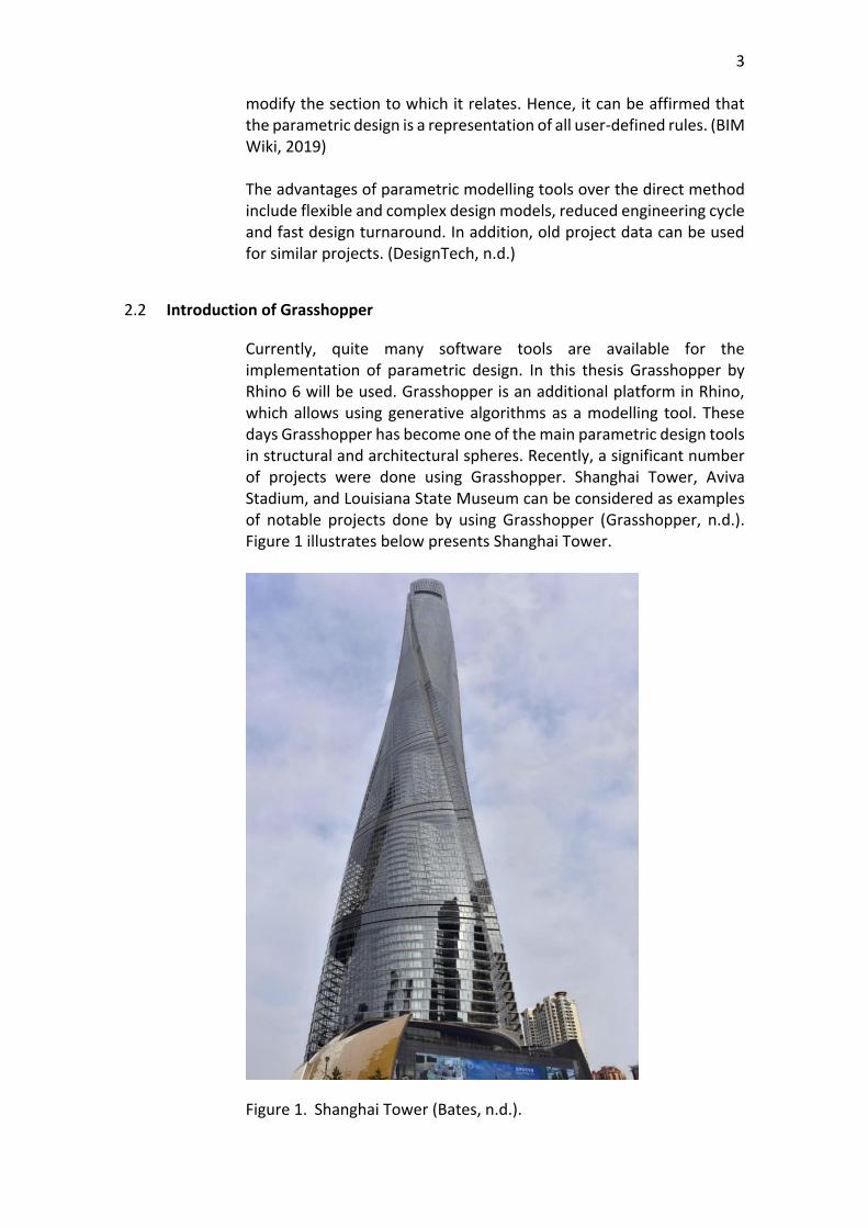
Currently, quite many software tools are available for the implementation of parametric design. In this thesis Grasshopper by Rhino 6 will be used. Grasshopper is an additional platform in Rhino, which allows using generative algorithms as a modelling tool. These days Grasshopper has become one of the main parametric design tools in structural and architectural spheres. Recently, a significant number of projects were done using Grasshopper. Shanghai Tower, Aviva Stadium, and Louisiana State Museum can be considered as examples of notable projects done by using Grasshopper (Grasshopper, n.d.). Figure 1 illustrates below presents Shanghai Tower.
Figure 1. Shanghai Tower (Bates, n.d.).
4
Because of the benefits that parametric design can provide to engineers, the Gensler team, which was in charge of the project of Shanghai Tower, decided to use Grasshopper as a modelling platform. During the design process, it was found that increasing the rotation angle of the building reduces the wind load on the façade. An option was selected that decreases the load by 24% compared to the rectangular shape of a building with the same height. This solution reduced the amount of material in the frame system. (Xia and Peng, 2012)
2.3 The principle operation of Grasshopper
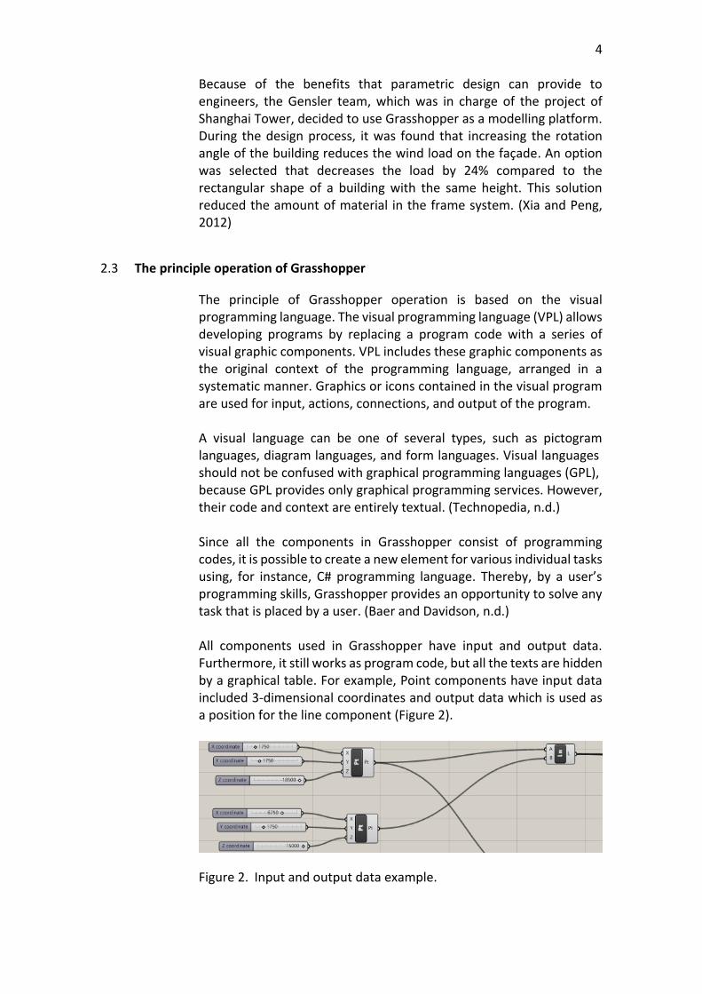
The principle of Grasshopper operation is based on the visual programming language. The visual programming language (VPL) allows developing programs by replacing a program code with a series of visual graphic components. VPL includes these graphic components as the original context of the programming language, arranged in a systematic manner. Graphics or icons contained in the visual program are used for input, actions, connections, and output of the program. A visual language can be one of several types, such as pictogram languages, diagram languages, and form languages. Visual languages should not be confused with graphical programming languages (GPL), because GPL provides only graphical programming services. However, their code and context are entirely textual. (Technopedia, n.d.) Since all the components in Grasshopper consist of programming codes, it is possible to create a new element for various individual tasks using, for instance, C# programming language. Thereby, by a user’s programming skills, Grasshopper provides an opportunity to solve any task that is placed by a user. (Baer and Davidson, n.d.) All components used in Grasshopper have input and output data. Furthermore, it still works as program code, but all the texts are hidden by a graphical table. For example, Point components have input data included 3-dimensional coordinates and output data which is used as a position for the line component (Figure 2).
Figure 2. Input and output data example.
5
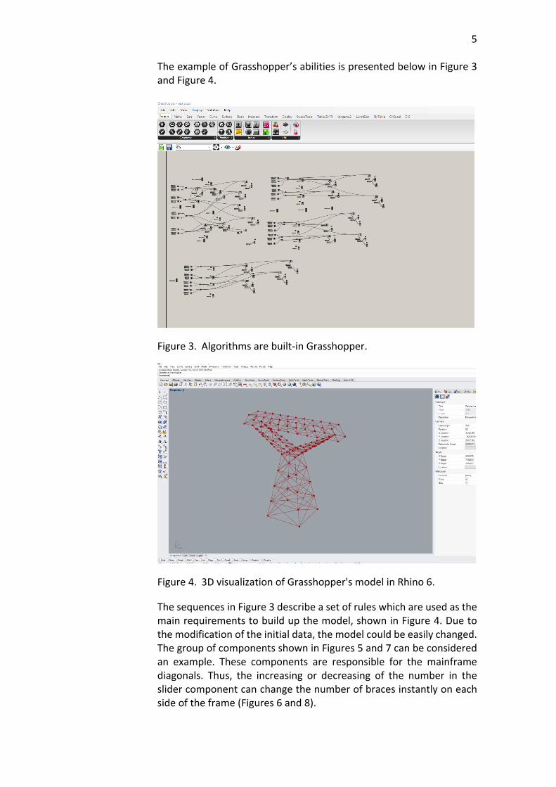
The example of Grasshopper’s abilities is presented below in Figure 3 and Figure 4.
Figure 3. Algorithms are built-in Grasshopper.
Figure 4. 3D visualization of Grasshopper's model in Rhino 6.
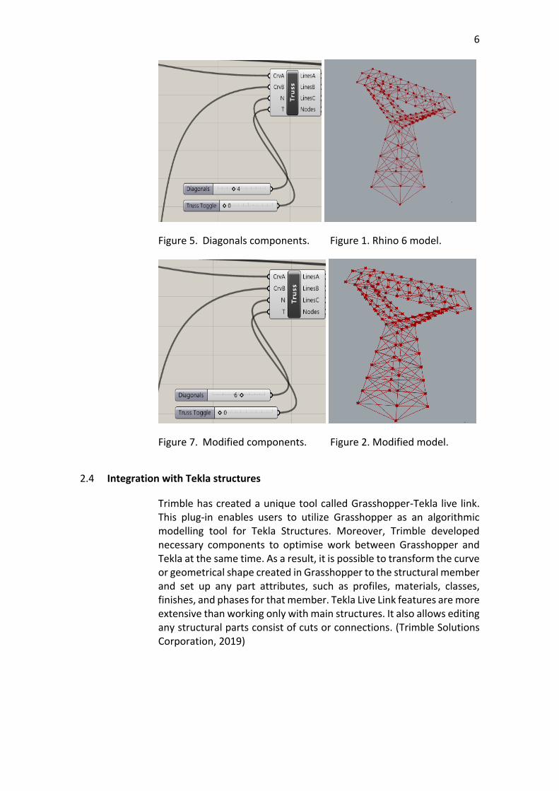
The sequences in Figure 3 describe a set of rules which are used as the main requirements to build up the model, shown in Figure 4. Due to the modification of the initial data, the model could be easily changed. The group of components shown in Figures 5 and 7 can be considered an example. These components are responsible for the mainframe diagonals. Thus, the increasing or decreasing of the number in the slider component can change the number of braces instantly on each side of the frame (Figures 6 and 8).
6
Figure 5. Diagonals components. Figure 1. Rhino 6 model.
Figure 7. Modified components. Figure 2. Modified model.
2.4 Integration with Tekla structures
Trimble has created a unique tool called Grasshopper-Tekla live link. This plug-in enables users to utilize Grasshopper as an algorithmic modelling tool for Tekla Structures. Moreover, Trimble developed necessary components to optimise work between Grasshopper and Tekla at the same time. As a result, it is possible to transform the curve or geometrical shape created in Grasshopper to the structural member and set up any part attributes, such as profiles, materials, classes, finishes, and phases for that member. Tekla Live Link features are more extensive than working only with main structures. It also allows editing any structural parts consist of cuts or connections. (Trimble Solutions Corporation, 2019)

7
Figure 9. List of Components for Grasshopper developed by Trimble
The same model from Figure 3 will be used to show the instant relationship between Grasshopper and Tekla Structures. Tekla model done by using Grasshopper is presented below (Figures 10 and 11).
Figure 3. Tekla model is done by using Grasshopper.
Figure 4. Trimble's components for Grasshopper.
8
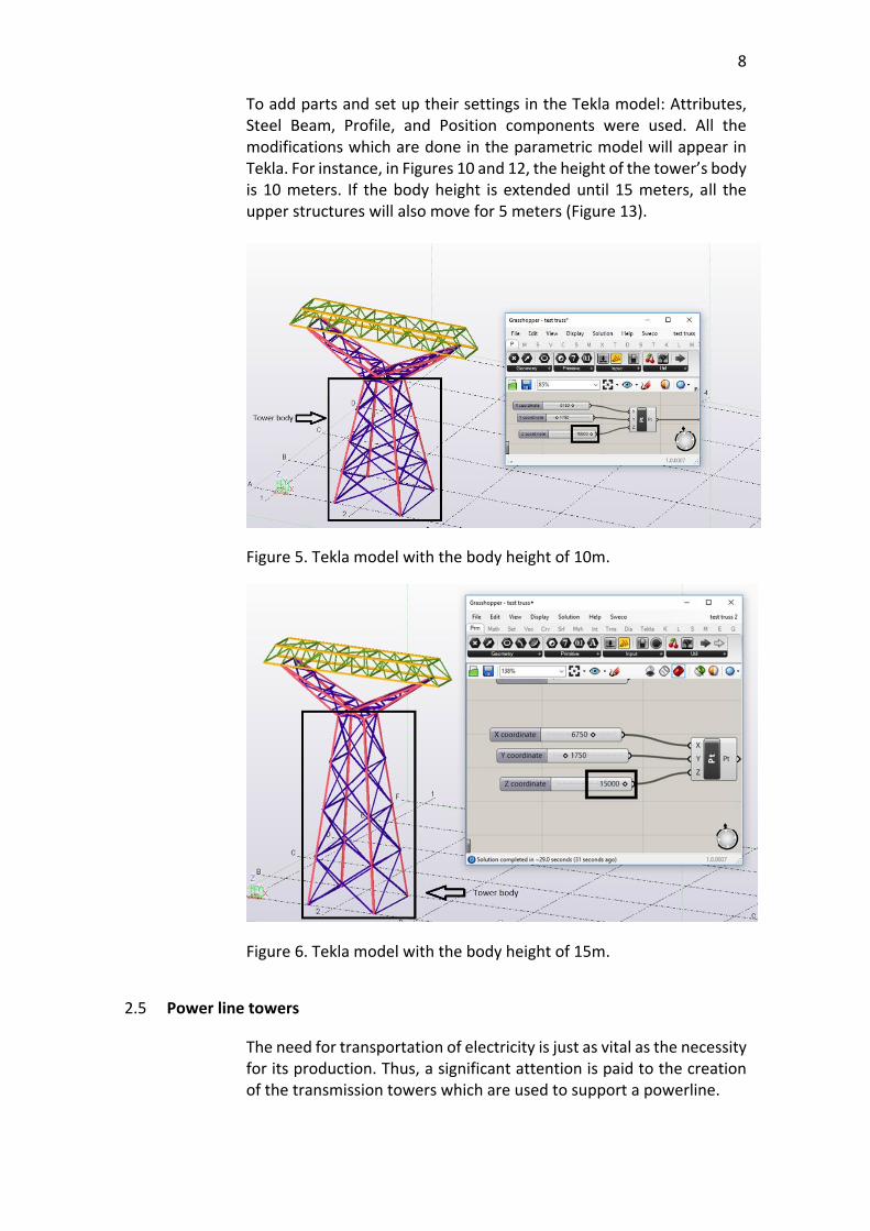
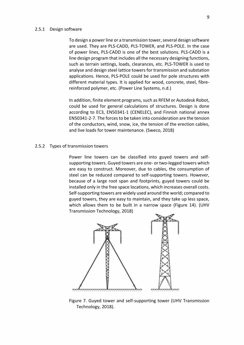
To add parts and set up their settings in the Tekla model: Attributes, Steel Beam, Profile, and Position components were used. All the modifications which are done in the parametric model will appear in Tekla. For instance, in Figures 10 and 12, the height of the tower’s body is 10 meters. If the body height is extended until 15 meters, all the upper structures will also move for 5 meters (Figure 13).
Figure 5. Tekla model with the body height of 10m.
Figure 6. Tekla model with the body height of 15m.
2.5 Power line towers
The need for transportation of electricity is just as vital as the necessity for its production. Thus, a significant attention is paid to the creation of the transmission towers which are used to support a powerline.
9
2.5.1 Design software
To design a power line or a transmission tower, several design software are used. They are PLS-CADD, PLS-TOWER, and PLS-POLE. In the case of power lines, PLS-CADD is one of the best solutions. PLS-CADD is a line design program that includes all the necessary designing functions, such as terrain settings, loads, clearances, etc. PLS-TOWER is used to analyse and design steel lattice towers for transmission and substation applications. Hence, PLS-POLE could be used for pole structures with different material types. It is applied for wood, concrete, steel, fibre-reinforced polymer, etc. (Power Line Systems, n.d.) In addition, finite element programs, such as RFEM or Autodesk Robot, could be used for general calculations of structures. Design is done according to EC3, EN50341-1 (CENELEC), and Finnish national annex EN50341-2-7. The forces to be taken into consideration are the tension of the conductors, wind, snow, ice, the tension of the erection cables, and live loads for tower maintenance. (Sweco, 2018)
2.5.2 Types of transmission towers
Power line towers can be classified into guyed towers and self-supporting towers. Guyed towers are one- or two-legged towers which are easy to construct. Moreover, due to cables, the consumption of steel can be reduced compared to self-supporting towers. However, because of a large root span and footprints, guyed towers could be installed only in the free space locations, which increases overall costs. Self-supporting towers are widely used around the world; compared to guyed towers, they are easy to maintain, and they take up less space, which allows them to be built in a narrow space (Figure 14). (UHV Transmission Technology, 2018)
Figure 7. Guyed tower and self-supporting tower (UHV Transmission Technology, 2018).
10
2.5.3 Lattice self-supported towers
The main factor in choosing the type of self-supporting towers is the amount of voltage that has to be transported through the towers. Also, lattice towers are divided according to their functionality into groups such as tension straight, tension angled, suspension straight, and suspension angled towers. Tension towers are fully self-supporting structures that create tension for the wiring of a powerline. This type of tower can be used when the transmission line changes direction by more than a few degrees or sometimes between suspension towers to limit the degree of collapse. Suspension straight towers are placed along straight powerline and used to suspend the cables. In addition, suspension angled towers are built to change the direction of a transmission route up to several degrees. (Walston, 2014) A transmission tower consists of parts listed below:
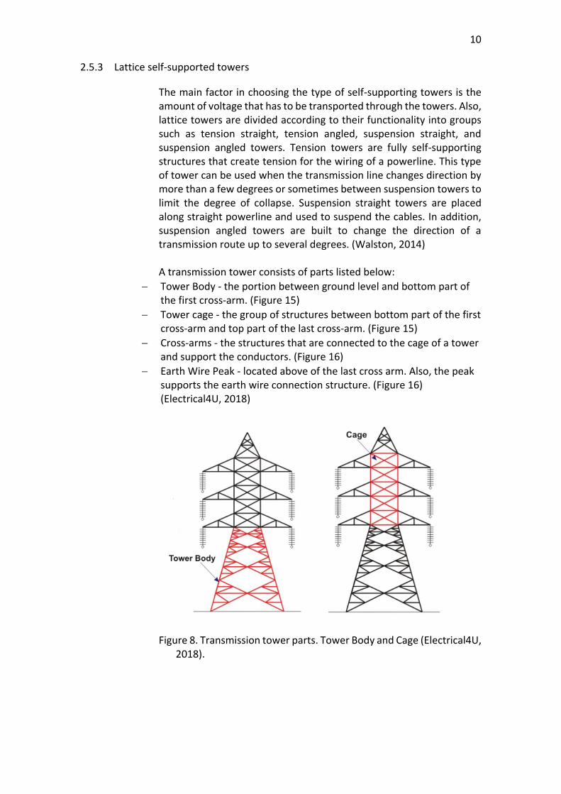
− Tower Body - the portion between ground level and bottom part of the first cross-arm. (Figure 15)
− Tower cage - the group of structures between bottom part of the first cross-arm and top part of the last cross-arm. (Figure 15)
− Cross-arms - the structures that are connected to the cage of a tower and support the conductors. (Figure 16)
− Earth Wire Peak - located above of the last cross arm. Also, the peak supports the earth wire connection structure. (Figure 16) (Electrical4U, 2018)
Figure 8. Transmission tower parts. Tower Body and Cage (Electrical4U, 2018).
11
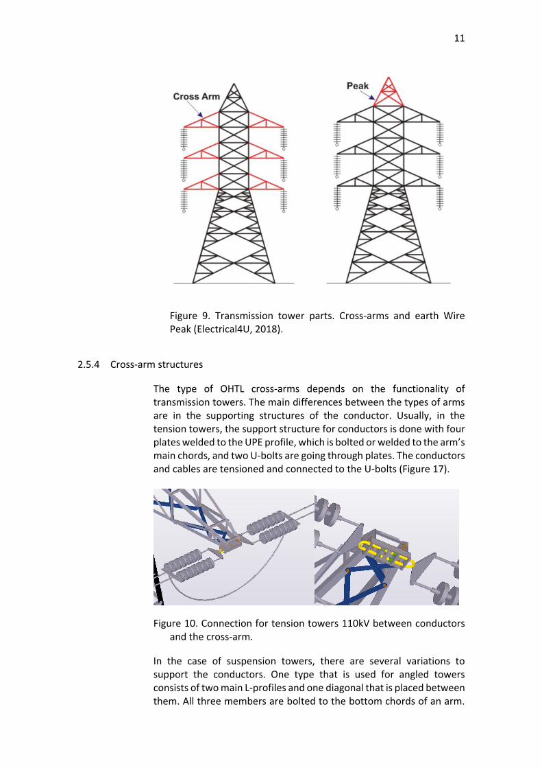
Figure 9. Transmission tower parts. Cross-arms and earth Wire Peak (Electrical4U, 2018).
2.5.4 Cross-arm structures
The type of OHTL cross-arms depends on the functionality of transmission towers. The main differences between the types of arms are in the supporting structures of the conductor. Usually, in the tension towers, the support structure for conductors is done with four plates welded to the UPE profile, which is bolted or welded to the arm’s main chords, and two U-bolts are going through plates. The conductors and cables are tensioned and connected to the U-bolts (Figure 17).
Figure 10. Connection for tension towers 110kV between conductors and the cross-arm.
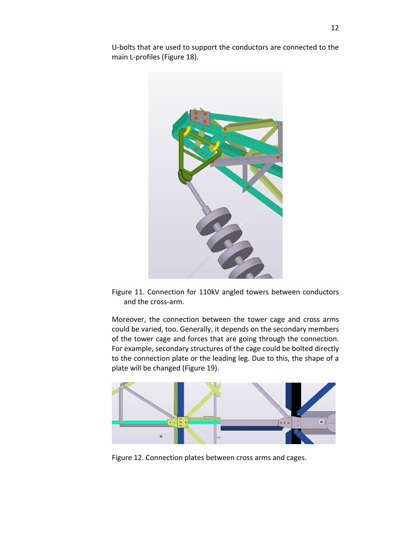
In the case of suspension towers, there are several variations to support the conductors. One type that is used for angled towers consists of two main L-profiles and one diagonal that is placed between them. All three members are bolted to the bottom chords of an arm.
12
U-bolts that are used to support the conductors are connected to the main L-profiles (Figure 18).
Figure 11. Connection for 110kV angled towers between conductors and the cross-arm.
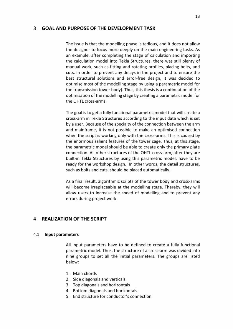
Moreover, the connection between the tower cage and cross arms could be varied, too. Generally, it depends on the secondary members of the tower cage and forces that are going through the connection. For example, secondary structures of the cage could be bolted directly to the connection plate or the leading leg. Due to this, the shape of a plate will be changed (Figure 19).
Figure 12. Connection plates between cross arms and cages.
13
3 GOAL AND PURPOSE OF THE DEVELOPMENT TASK
The issue is that the modelling phase is tedious, and it does not allow the designer to focus more deeply on the main engineering tasks. As an example, after completing the stage of calculation and importing the calculation model into Tekla Structures, there was still plenty of manual work, such as fitting and rotating profiles, placing bolts, and cuts. In order to prevent any delays in the project and to ensure the best structural solutions and error-free design, it was decided to optimise most of the modelling stage by using a parametric model for the transmission tower body). Thus, this thesis is a continuation of the optimisation of the modelling stage by creating a parametric model for the OHTL cross-arms. The goal is to get a fully functional parametric model that will create a cross-arm in Tekla Structures according to the input data which is set by a user. Because of the specialty of the connection between the arm and mainframe, it is not possible to make an optimised connection when the script is working only with the cross-arms. This is caused by the enormous salient features of the tower cage. Thus, at this stage, the parametric model should be able to create only the primary plate connection. All other structures of the OHTL cross-arm, after they are built-in Tekla Structures by using this parametric model, have to be ready for the workshop design. In other words, the detail structures, such as bolts and cuts, should be placed automatically. As a final result, algorithmic scripts of the tower body and cross-arms will become irreplaceable at the modelling stage. Thereby, they will allow users to increase the speed of modelling and to prevent any errors during project work.
4 REALIZATION OF THE SCRIPT
4.1 Input parameters
All input parameters have to be defined to create a fully functional parametric model. Thus, the structure of a cross-arm was divided into nine groups to set all the initial parameters. The groups are listed below: 1. Main chords 2. Side diagonals and verticals 3. Top diagonals and horizontals 4. Bottom diagonals and horizontals 5. End structure for conductor’s connection
14
6. Connecting plates between arm and tower cage 7. End connecting plates 8. Member attributes 9. Cuts All input parameters are presented and described in Appendix 1.
4.2 Instruction
The step-by-step instruction is provided in Appendix 2.
4.3 Parametric model tests
Five different sets of input parameters are used in order to verify that the parametric model for the OHTL cross-arms is working correctly. The principle of checking is based on the creation of drawings along different views for each plane of the structure. Dimensions are presented at the drawings to compare them with input data. During all tests the Part Attributes parameters are used as default values and all cuts are presented. The tests are provided in Appendix 3.
5 CONCLUSION
As a result, the parametric algorithm was created during autumn 2019. In conclusion, it can be stated that the use of the parametric optimisation tool for the OHTL cross-arms is beneficial. The script provides a fully adjustable parametric model for the cross-arm structures including not only the main members, but also bolts, cuts, and member attributes. Moreover, it takes short computational time to model the cross-arm structure. During the thesis, five tests were presented to verify the performance of the algorithm. All the tests passed the verification successfully. Thus, it offers significant advantages, such as error-free design and time-saving. In the future, this parametric model can be updated to create earth wire structures. It will also be possible to combine all scripts for the lattice tower in order to produce a full optimisation of a tower.
15
REFERENCES
Baer, S. & Davidson, S. (n.d.). Task capable Components. Retrieved 3 November 2019 from https://developer.rhino3d.com/guides/grasshopper/programming-task-capable-component/ Bates. (n.d.). BOMA 360 Reaches New Heights with Shanghai Tower. Retrieved 2 November 2019 from https://www.boma.org/BOMA/Recognition-Awards/Case_Studies/2018/November_December.aspx BIM Wiki. (2019). Parametric modelling. Retrieved 2 November 2019 from https://www.designingbuildings.co.uk/wiki/Parametric_modelling DesignTech. (n.d.). Parametric modelling. Retrieved 2 November 2019 from https://www.designtechsys.com/articles/parametric-modelling Electrical4U. (2018). Electrical Transmission Tower Types and Design. Retrieved 6 November 2019 from https://www.electrical4u.com/electrical-transmission-tower-types-and-design/ Fingrid Oy. (2009). 110Kv Transmission line. Retrieved 12 November 2019 from Document FG-400-3-511 Fu. (2018). Design and Analysis of Tall and Complex Structures. Retrieved 2 November 2019 from https://www.sciencedirect.com/topics/engineering/parametric-modeling Grasshopper. (n.d.). Architecture projects. Retrieved 2 November 2019 from https://www.grasshopper3d.com/page/architecture-projects Power Line Systems. (n.d.). Products. Retrieved 6 November 2019 from https://www.powerlinesystems.com/products Rudeck. (2014). Parametric or Direct Modelling. Retrieved 2 November 2019 from https://www.concurrent-engineering.co.uk/blog/parametric-or-direct-modelling-which-is-the-best-approach
16
Smirnov. (2016). 3D modelling. Retrieved 2 November 2019 from https://vrender.com/what-is-3d-modeling/ Sweco Rakennetekniikka. (2018). Technopedia. (n.d.). Visual Programming language (VPL). Retrieved 2 November 2019 from https://www.techopedia.com/definition/22855/visual-programming-language-vpl Trimble Solutions Corporation. (2019). Grasshopper-Tekla Live Link. Retrieved 3 November 2019 from https://teklastructures.support.tekla.com/not-version-specific/en/ext_grasshopperteklalink UHV Transmission Technology. (2018). UHVDC Transmission Lines. Retrieved 6 November 2019 from https://www.sciencedirect.com/topics/engineering/guyed-tower Walston. (2014). Transmission Towers. Retrieved 6 November 2019 from https://prezi.com/ex9omm1x7wax/a-transmission-tower-is-a-tall-structure-usually-a-steel-l/ Xia, J. and Peng, M. (2012). The parametric design of Shanghai Tower’s Form and Façade. Retrieved 2 November 2019 from https://global.ctbuh.org/resources/papers/download/1006-the-parametric-design-of-shanghai-towers-form-and-facade.pdf