Embed Size (px)
Citation preview
International Research Journal of Engineering and Technology (IRJET) e-ISSN: 2395-0056
Volume: 05 Issue: 03 | Mar-2018 www.irjet.net p-ISSN: 2395-0072
© 2018, IRJET | Impact Factor value: 6.171 | ISO 9001:2008 Certified Journal | Page 3086
Parametric Optimization of Flexure Bearing using FEA
Pratik Kadam1, Abhilash Hemaraj1, Anup Nair1, Siddhesh Bhosale1, Prof. Neethu Nair2, Prof. Ajay Ingle2
1U.G. Student, Department of Mechanical Engineering, D.R.I.E.M.S, Neral, Raigad, Maharashtra, India. 2Associate Professor. Department of Mechanical Engineering, D.R.I.E.M.S, Neral, Raigad, Maharashtra, India.
----------------------------------------------------------------***--------------------------------------------------------------- Abstract - A Flexure Bearing is one such type of bearing which is used for precision applications such as programmable focusing mechanism, linear compressor, cryocooler, etc. These bearings are compact and inexpensive. It is a fairly new concept and hence there is scope for further optimization. Designing a flexure bearing involves selection of various different parameters such as its thickness, type of profile, width of profile, etc. Present paper focuses on optimizing the three-arm spiral flexure bearing used in flexure bearing by establishing relationships between selected parameters viz. thickness, slot width, shape factor and sweep angle and their impact on stress levels induced in bearing. The stress induced should be minimum for longer life of bearing. Taguchi’s Design of Experiments is utilized for this purpose and simulations are carried out on Ansys Workbench and modelling is done using CATIA and MATLAB.
1. INTRODUCTION Flexure Bearings used in linear bearings are bearings which provide constrained motion to a piston shaft. They help in eliminating frictional losses resulting from contact between piston and cylinder. Use of flexure bearings thus improves the life of the compressors. Also, they can be operated in vacuum conditions, and at high and low temperatures alike which makes them suitable for space applications. However, flexure bearings require use of materials that are able to endure continuous flexing. These bearings are used in stacks and are clamped using holes present on the periphery of the bearing. Various different types of flexure bearings having different profiles are used for different applications. Some of them are shown in Fig. 1. However, the most common flexure bearing used is three-arm spiral flexure bearing. A central hole is provided for the movement of piston shaft.
Fig -1: Different types of profiles for flexure bearings. The present paper is concentrated on establishing critical parameters which result in impact on stress levels of these bearings using Taguchi’s DOE. The four parameters selected are thickness, slot width of spiral arms, shape
factor of spiral arms and sweep angle of spiral arms. Optimization is done for minimum stress levels as it will result in longer life.
2. TAGUCHI’S DESIGN OF EXPERIMENTS. It was decided to use three different levels of the four selected parameters for optimization process. Thus, the total number of different geometries possible were 81. It would be cumbersome to generate 81 geometries and analyze them. Hence, L9 orthogonal array was used to reduce the number of experiments. The different parameters selected and their levels are shown below.
Table -1: Parameters and Their Levels
Thickness 0.5mm 0.75mm 1mm
Slot Width 0.5mm 0.75mm 1mm
Shape Factor 0 0.05 0.1
Sweep Angle 480 600 720
Using the above values of parameters, the below L9 Orthogonal Array was generated.
Table -2: L9 Orthogonal Array
EXP NO.
THICK-NESS
SLOT WIDTH
SHAPE FACTOR
SWEEP ANGLE
(A) (B) (C) (D)
1 0.5 0.5 0 480
2 0.5 0.75 0.05 600
3 0.5 1 0.1 720
4 0.75 0.5 0.05 720
5 0.75 0.75 0.1 480
6 0.75 1 0 600
7 1 0.5 0.1 600
8 1 0.75 0 720
9 1 1 0.05 480
Von Misses Stress or equivalent stress is selected as the output factor with material being selected as a noise factor.
3. DESIGNING OF FLEXURE BEARING The diameter of the bearing was decided to be of 90mm. [1] The central hole and periphery holes were of 6mm
International Research Journal of Engineering and Technology (IRJET) e-ISSN: 2395-0056
Volume: 05 Issue: 03 | Mar-2018 www.irjet.net p-ISSN: 2395-0072
© 2018, IRJET | Impact Factor value: 6.171 | ISO 9001:2008 Certified Journal | Page 3087
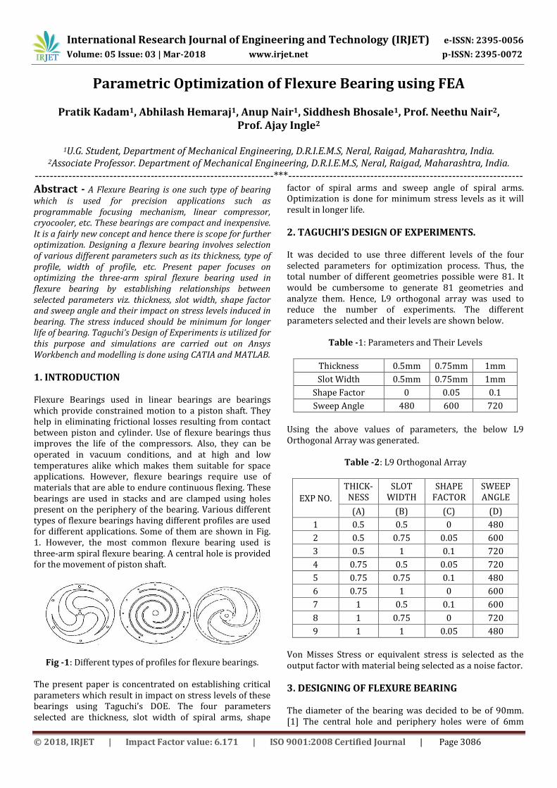
each. The spiral profile was generated using the equation below [2]: -
R = Ri + (Ro-Ri) * [Ө/Өo + f*Sin(2*π*Ө/Өo)] … (1)
Where,
Ri = Inner Radius of Spiral = 8mm
Ro = Outer Radius of Spiral = 32mm
Өo = 480, 600, 720.
f = 0, 0.05, 0.1. Using MATLAB codes, the points for the spiral curve were generated. Using these points, a curve was generated on the CATIA Generative Shape Design and slotted for different levels of slot width. Using this process 9 different geometries were created.
Fig -2: Design for Exp. No. 1.
4. FEA ANALYSIS
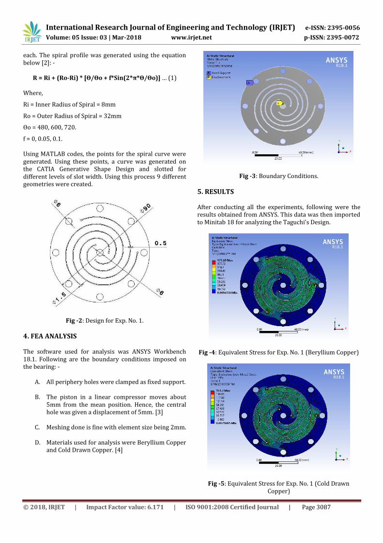
The software used for analysis was ANSYS Workbench 18.1. Following are the boundary conditions imposed on the bearing: -
A. All periphery holes were clamped as fixed support.
B. The piston in a linear compressor moves about 5mm from the mean position. Hence, the central hole was given a displacement of 5mm. [3]
C. Meshing done is fine with element size being 2mm.
D. Materials used for analysis were Beryllium Copper and Cold Drawn Copper. [4]
Fig -3: Boundary Conditions.
5. RESULTS After conducting all the experiments, following were the results obtained from ANSYS. This data was then imported to Minitab 18 for analyzing the Taguchi’s Design.
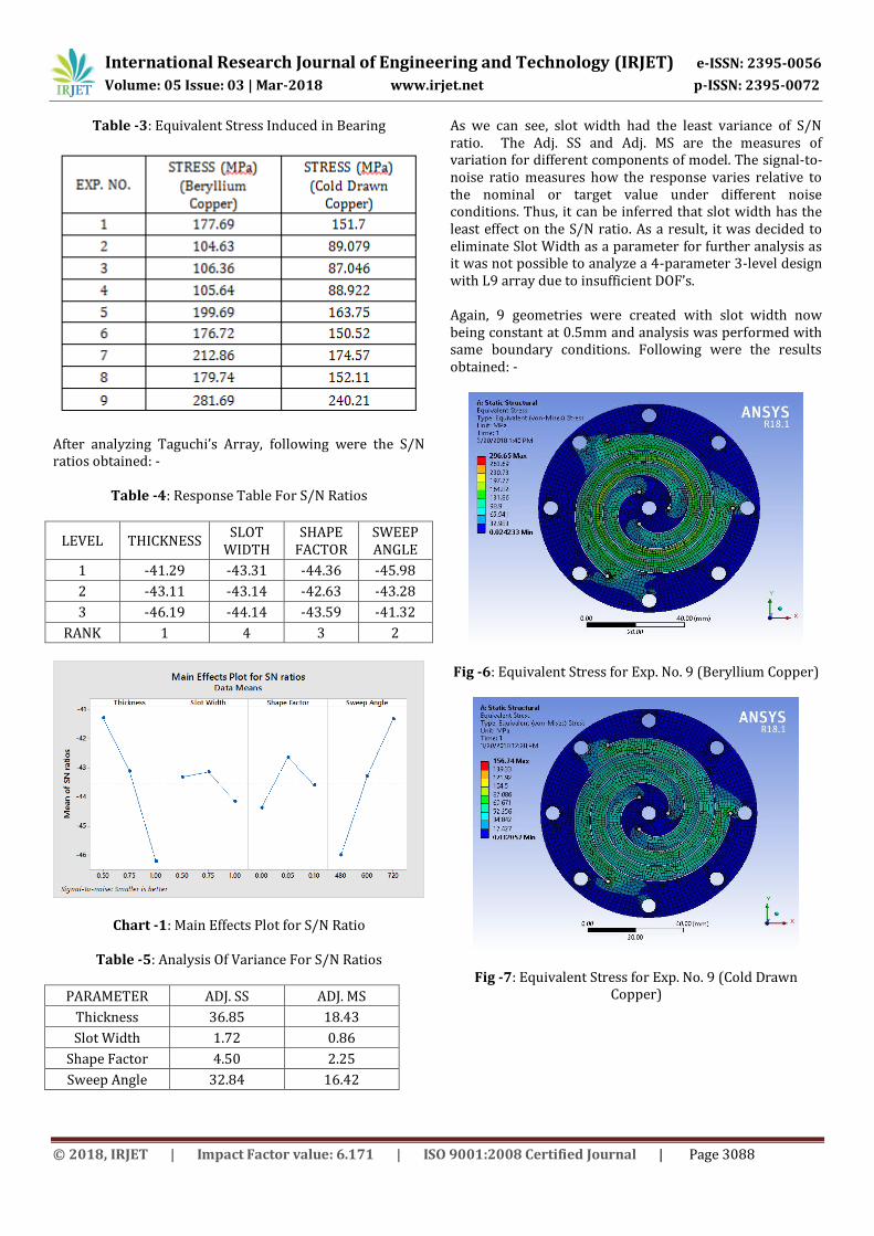
Fig -4: Equivalent Stress for Exp. No. 1 (Beryllium Copper)
Fig -5: Equivalent Stress for Exp. No. 1 (Cold Drawn Copper)
International Research Journal of Engineering and Technology (IRJET) e-ISSN: 2395-0056
Volume: 05 Issue: 03 | Mar-2018 www.irjet.net p-ISSN: 2395-0072
© 2018, IRJET | Impact Factor value: 6.171 | ISO 9001:2008 Certified Journal | Page 3088
Table -3: Equivalent Stress Induced in Bearing
After analyzing Taguchi’s Array, following were the S/N ratios obtained: -
Table -4: Response Table For S/N Ratios
LEVEL THICKNESS SLOT
WIDTH SHAPE
FACTOR SWEEP ANGLE
1 -41.29 -43.31 -44.36 -45.98
2 -43.11 -43.14 -42.63 -43.28
3 -46.19 -44.14 -43.59 -41.32
RANK 1 4 3 2
Chart -1: Main Effects Plot for S/N Ratio
Table -5: Analysis Of Variance For S/N Ratios
PARAMETER ADJ. SS ADJ. MS
Thickness 36.85 18.43
Slot Width 1.72 0.86
Shape Factor 4.50 2.25
Sweep Angle 32.84 16.42
As we can see, slot width had the least variance of S/N ratio. The Adj. SS and Adj. MS are the measures of variation for different components of model. The signal-to-noise ratio measures how the response varies relative to the nominal or target value under different noise conditions. Thus, it can be inferred that slot width has the least effect on the S/N ratio. As a result, it was decided to eliminate Slot Width as a parameter for further analysis as it was not possible to analyze a 4-parameter 3-level design with L9 array due to insufficient DOF’s. Again, 9 geometries were created with slot width now being constant at 0.5mm and analysis was performed with same boundary conditions. Following were the results obtained: -
Fig -6: Equivalent Stress for Exp. No. 9 (Beryllium Copper)
Fig -7: Equivalent Stress for Exp. No. 9 (Cold Drawn Copper)
International Research Journal of Engineering and Technology (IRJET) e-ISSN: 2395-0056
Volume: 05 Issue: 03 | Mar-2018 www.irjet.net p-ISSN: 2395-0072
© 2018, IRJET | Impact Factor value: 6.171 | ISO 9001:2008 Certified Journal | Page 3089
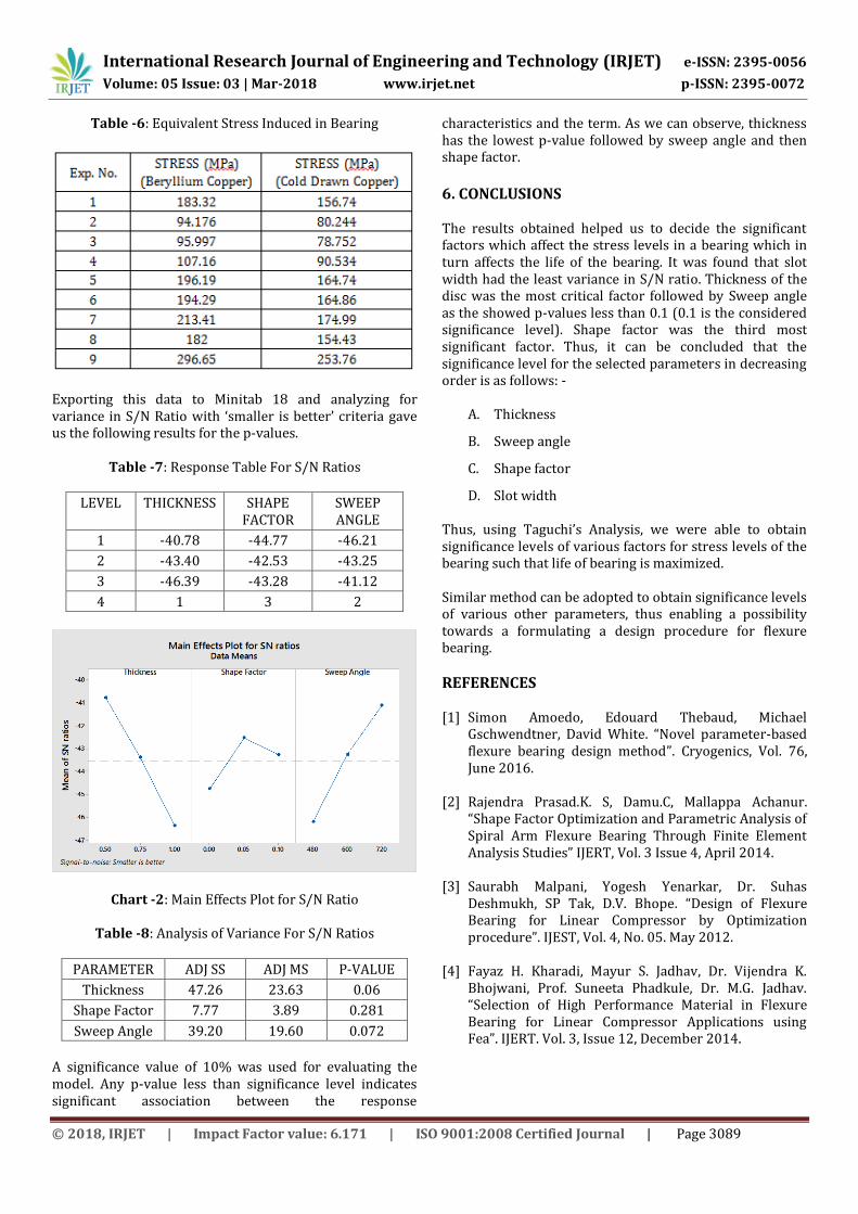
Table -6: Equivalent Stress Induced in Bearing
Exporting this data to Minitab 18 and analyzing for variance in S/N Ratio with ‘smaller is better’ criteria gave us the following results for the p-values.
Table -7: Response Table For S/N Ratios
LEVEL THICKNESS SHAPE FACTOR
SWEEP ANGLE
1 -40.78 -44.77 -46.21
2 -43.40 -42.53 -43.25
3 -46.39 -43.28 -41.12
4 1 3 2
Chart -2: Main Effects Plot for S/N Ratio
Table -8: Analysis of Variance For S/N Ratios
PARAMETER ADJ SS ADJ MS P-VALUE
Thickness 47.26 23.63 0.06
Shape Factor 7.77 3.89 0.281
Sweep Angle 39.20 19.60 0.072
A significance value of 10% was used for evaluating the model. Any p-value less than significance level indicates significant association between the response
characteristics and the term. As we can observe, thickness has the lowest p-value followed by sweep angle and then shape factor.
6. CONCLUSIONS The results obtained helped us to decide the significant factors which affect the stress levels in a bearing which in turn affects the life of the bearing. It was found that slot width had the least variance in S/N ratio. Thickness of the disc was the most critical factor followed by Sweep angle as the showed p-values less than 0.1 (0.1 is the considered significance level). Shape factor was the third most significant factor. Thus, it can be concluded that the significance level for the selected parameters in decreasing order is as follows: -
A. Thickness
B. Sweep angle
C. Shape factor
D. Slot width Thus, using Taguchi’s Analysis, we were able to obtain significance levels of various factors for stress levels of the bearing such that life of bearing is maximized. Similar method can be adopted to obtain significance levels of various other parameters, thus enabling a possibility towards a formulating a design procedure for flexure bearing.
REFERENCES [1] Simon Amoedo, Edouard Thebaud, Michael
Gschwendtner, David White. “Novel parameter-based flexure bearing design method”. Cryogenics, Vol. 76, June 2016.
[2] Rajendra Prasad.K. S, Damu.C, Mallappa Achanur.
“Shape Factor Optimization and Parametric Analysis of Spiral Arm Flexure Bearing Through Finite Element Analysis Studies” IJERT, Vol. 3 Issue 4, April 2014.
[3] Saurabh Malpani, Yogesh Yenarkar, Dr. Suhas
Deshmukh, SP Tak, D.V. Bhope. “Design of Flexure Bearing for Linear Compressor by Optimization procedure”. IJEST, Vol. 4, No. 05. May 2012.
[4] Fayaz H. Kharadi, Mayur S. Jadhav, Dr. Vijendra K.
Bhojwani, Prof. Suneeta Phadkule, Dr. M.G. Jadhav. “Selection of High Performance Material in Flexure Bearing for Linear Compressor Applications using Fea”. IJERT. Vol. 3, Issue 12, December 2014.