Embed Size (px)
Citation preview

HBRC Journal (2014) 10, 108–116
Housing and Building National Research Center
HBRC Journal
http://ees.elsevier.com/hbrcj
FULL LENGTH ARTICLE
Parametric study of the structural and in-plane
buckling analysis of ogee arches
* Tel.: +20 2 37617057x1606, mobile: +20 127 645 9099; fax: +20 2
33351564.E-mail address: [email protected]
Peer review under responsibility of Housing and Building National
Research Center.
Production and hosting by Elsevier
1687-4048 ª 2013 Production and hosting by Elsevier B.V. on behalf of Housing and Building National Research Center.
http://dx.doi.org/10.1016/j.hbrcj.2013.07.001
Ghada M. El-Mahdy *
Structures and Metallic Construction Research Institute, Housing and Building National Research Center (HBRC), 87 El-Tahrir St.,Dokki, Giza, PC 11511, PO Box 1770, Cairo, Egypt
Received 24 April 2013; revised 16 July 2013; accepted 20 July 2013
KEYWORDS
Arches;
Buckling analysis;
Finite element analysis;
Geometry;
Ogee shaped arch
Abstract As part of a pilot project an ogee arch is being studied as a self-supporting skin skylight
for the Housing and Building National Research Center’s (HBRC) patio. The ogee arch consists of
a pair of two tangential circular arcs making an arch shape. The geometry of the arch depends on
several interrelated variables including the angles subtended by the arcs, the ratio of the radii of the
two arcs, and the height of the arch. This paper provides curves for designing the geometry of ogee
arches. The structural analysis of two-hinged ogee arches under different cases of loading is outlined
deriving expressions for the horizontal base thrust and plotting their graphs. A parametric study of
the antisymmetric in-plane buckling behavior of ogee arches is presented using a finite element
eigenvalue buckling analysis for several cases of loading. The finite element models consist of beam
elements and have varying geometrical dimensions representing different shapes of ogee arches. The
structural response of the arches is verified through a linear finite element analysis. The results of
the buckling analysis are verified through a nonlinear finite element analysis with initial imperfec-
tions. It is found that the buckling load is a function of the ratio of the height-to-base radius of the
arch and expressions for the lower bound buckling load are derived as a function of this height-to-
base radius ratio.ª 2013 Production and hosting by Elsevier B.V. on behalf of Housing and Building National Research
Center.
Introduction
An arch is a planar structure that spans a space and supports aload. The significance of the arch is that it provides an estheti-cally pleasing shape, as well as, theoretically provides a structurewhich eliminates tensile stresses in spanning a great amount of
open space. The forces are mainly resolved into compressivestresses. By using the arch configuration significant spans canbe achieved. However, one downside is that an arch pushes out-
ward at the base, and the horizontal reaction force (or thrust)needs to be restrained in some way. Arches can be fixed, hinged,

Parametric study of the structural and in-plane buckling analysis of ogee arches 109
or have 3 hinges, as shown in Fig. 1. Arches can take severalshapes consisting of a combination of lines, arcs of circles, andother curves as shown in Fig. 2.
As part of a pilot project on sustainable or green construc-tion at the Housing and Building National Research Center(HBRC) [1], it is proposed to cover the open patio space at
the ground floor of HBRC’s main building with a self-support-ing skin skylight. The HBRC logo consists of an ogee shapedarch with a symbolic sun behind it, hence the new skylight un-
der consideration could take the shape of an ogee arch. Thesun symbolizes renewable energy and light, and the arch itselfbeing symbolic of HBRC’s leading role in Egypt in sustainableconstruction. As there is very little data on ogee arches, the
subject of this research is the structural and in-plane bucklinganalysis of two-hinged ogee shaped arches.
Ogee is a curved shape somewhat like an ‘‘S’’ consisting of
two arcs that curve in opposite senses, so that the ends are tan-gential. In architecture, the term ogee is used for a moldingwith a profile consisting of a lower concave arc flowing into
a convex arc. The ogee arch dates back to ancient Persianand Greek architecture [2] and is also found in Gothic stylearchitecture. Ogee is also a mathematical term meaning
‘‘inflection point’’. In fluid mechanics, the term is used forogee-shaped aerodynamic profiles, a good example of whichis the wing of the Concorde aeroplane. As the upper curvesof the ogee arch are reversed, it cannot bear a heavy load.
However for the purpose of a self-supporting skin skylight thatwill only be exposed to its own weight and wind loads, the ogeearch is a suitable solution.
Previous literature
An extensive bibliography on the stability of arches prior to
1970 is given by DaDeppo and Schmidt [3]. The Handbookof Structural Stability [4] gives an overview of results of stabil-ity research of arches in which either the equations or graphs
of the quoted literature are reproduced. An extensive state-of-the-art report on elastic and inelastic stability of arches isgiven by Fukumoto [5]. Singer et al. [6] provide a chapter on
experimental research that has been conducted on arches. Kingand Brown [7] present a comprehensive study for the practicaldesign of steel curved beams and arches.
Three-hinged arch Two-hinged arch Fixed-fixed arch
Fig. 1 Statical system of arches.
Semi-circular Segmental arch Lancet arch
Three-foiled
Eliptical arch
Inflexed arch
Parabolic arch
Tudor arch Ogee arch Reverse ogeehcrahcradepsuc
arch
Fig. 2 Common shapes of arches.
Early papers on arch stability devoted to linear stabilityproblems where no bending moments were induced in the archbefore buckling were summarized by Austin [8], Austin and
Ross [9], and Timoshenko and Gere [10]. More recent resultson the stability of tapered arches are reported by Wolde-Tin-saie and Foadian [11]. Nonlinear elastic stability where bend-
ing moments are induced in the arch before buckling ishandled by Austin and Ross [9]. The problem of unsymmetri-cal loading was studied by Kuranishi and Lu [12], Chang [13],
and Harrison [14]. For the same dead and live load intensities,it was found that unsymmetrically distributed load alwaysgoverns.
The limit analysis of stocky arches was first presented by
Onat and Prager [15]. A more recent theoretical method forcalculating the plastic collapse load of stocky arches is givenby Spoorenburg et al. [16]. The behavior of slender arches in
pure compression is very much like that of a column and itis common to express the buckling strength of such arches interms of axial thrust at the quarter point of the arch using Eu-
ler load [17]. Pi and Trahair [18] and Pi and Bradford [19] stud-ied the in-plane inelastic stability of hinged and fixed circulararches with I-shape cross sections with different load cases
and subtended angles. Other nonlinear buckling studies on ar-ches were made by Pi and Trahair [20], Pi et al. [21], and Yauand Yang [22].
International building standards are compared with each
other in Stability of Metal Structures, a World View [23]. TheEurocode 3, Part 2 [24] provides charts with effective lengthfactors for the elastic in-plane buckling of circular, parabolic,
and catenary arches with unmovable supports and severalarticulations. For tied arches with vertical hangers, effectivelengths are also given, as it is a criterion which indicates if
the arch is prone to snap-through buckling. AASHTO [25]provides effective-length factors for fixed, two-hinged andthree-hinged arches with rise-to-span ratios of 0.1–0.4.
Geometry of ogee arch
The ogee arch is composed of a pair of two discrete circular
arcs with independent radii. Hence, there are many geometri-cal variables to be determined namely, the radius of the lowerarc which is half the span of the arch, R1, the radius of theupper arc, R2, the angle subtended by the lower arc, 90-a,the angle subtended by the upper arc, b, as well as the overallheight of the arch, h. These variables are shown in Fig. 3. Fromthe geometry of the arch the coordinates of the peak of the
arch, point 3, can be expressed as
x3 ¼ ðR1 þ R2Þ sin a� R2 sinðaþ bÞ ¼ 0 ð1Þ
y3 ¼ ðR1 þ R2Þ cos a� R2 cosðaþ bÞ ¼ h ð2Þ
Fig. 3 Geometry of ogee arch.

0
10
20
30
40
50
60
70
80
90
1.0 1.1 1.2 1.3 1.4 1.5 1.6 1.7 1.8 1.9 2.0
h/R1
β o
α = 45ο
α = 40οα = 35ο
α = 30οα = 25ο
α = 20οα = 15οα = 10οα = 5ο
Fig. 4 Relationship of h/R1 versus angle b.
Fig. 6 Statical system of two-hinged ogee arch.
0
5
10
15
20
25
30
35
40
45
1.0 1.1 1.2 1.3 1.4 1.5 1.6 1.7 1.8 1.9 2.0
h/R1
R2/
R1
α=
5o
α=
10o α
= 1
5o
α=
20o
α=
40o
α=
35o
α=
30o
α=
25o
α=
45o
Fig. 5 Relationship of h/R1 versus R2/R1.
110 G.M. El-Mahdy
Eliminating R1 from these two simultaneous equations andsimplifying gives the expression for R2/h as
R2
h¼ sin a
sin bð3Þ
Substituting Eq. (3) into Eq. (1) and simplifying gives the
expression for R1/h as
R1
h¼ sinðaþ bÞ � sin a
sinbð4Þ
The radius of the upper curve R2 can be expressed in terms ofR1, a, and b as
R2
R1
¼ sin asinðaþ bÞ � sin a
ð5Þ
Eqs. (3)–(5) must be solved iteratively to determine all the
geometric variables of an ogee arch, so to simplify the processof design the graphs in Figs. 4 and 5 have been developed todetermine the geometric variables for a specific height-to-half
span ratio, h/R1. Fig. 4 plots the relationship between the ratioh/R1 for different values of angle a such that angle b can bedetermined from these independent variables. Fig. 5 plots the
relationship between the ratio h/R1 for different values of anglea such that the ratio R2/R1 can be determined. It is to be notedthat Eqs. (3)–(5) are only valid for practical values of h/R1 as
for higher ratios the left and right curves of the arch overlapeach other suggesting that there are two solutions to the prob-lem a practical one and an imaginary one. In Fig. 4 this is lim-ited to an h/R1 value of 2 or an angle b value of 90�.
Structural analysis of ogee arch
Arches behave like two-dimensional beams spanning an openspace, but unlike simple beams arches have a horizontal thrust
resisting the tendency of the arch to open out. The commonstatical systems of an arch can be either a three-hinged arch,a two-hinged arch, or a fixed–fixed arch as shown in Fig. 1.
For most common arch applications the two-hinged arch isthe most practical and is the statical system used in thisresearch.
Horizontal thrust
The arch is assumed to be a two hinged arch with horizontalbase reactions H, as shown in Fig. 6. To analyze this arch
the principal of virtual work [26] or minimum strain energy[27] is used giving the horizontal support reaction as
H ¼RMyds=EIRy2ds=EI
ð6Þ
where M is the bending moment of the applied load case for a
statically determinate simply supported arch, y is the distancefrom the base of the arch and represents the bending momentdue to a unit horizontal load applied at the released support ofthe statically determinate simply supported arch, ds is the infin-
itesimal distance along the length of the arch, and EI is thebending rigidity of the arch (E being the modulus of elasticityand I the moment of inertia of the cross-section about the axis
of bending). For the ogee arch, two circular coordinate sys-tems are required as shown in Fig. 6; the first for the lower partof the arch using h as the variable and integrating the moments
from h = a to h = p/2, and the second for the upper part ofthe arch using / as the variable and integrating the momentsfrom / = a to / = (a + b). The horizontal reaction that pre-
vents the spread of the arch depends on the type of loading ap-plied to the arch. Three cases of loading are analyzed namely aconcentrated load P at the peak of the arch (midspan), a uni-formly distributed vertical load acting along the horizontal
projection w, and a uniformly distributed horizontal load act-ing along the vertical projection wh, which are shown in Fig. 7.
Case (1): Concentrated load at midspan
For a concentrated load P at midspan the horizontal reactioncalculated using Eq. (6) and using the relationship for R2 as afunction of R1 from Eq. (5) is
H ¼12PðA1 þ 4B1ÞC1 þ 4D1
ð7Þ

Fig. 7 Load cases considered in structural analysis for horizontal thrust reaction.
Parametric study of the structural and in-plane buckling analysis of ogee arches 111
where
A1 ¼ 3� 4 sin a� cos 2a
B1 ¼12bð1� sin aÞ sin 2asinðaþ bÞ � sin a
þ sin asinðaþ bÞ � sin a
� �2
�bðcos a� sin 2aþ sin aþ cos 2aÞ
� sinðaþ bÞ � cosð2aþ bÞ
" #
þ sin asinðaþ bÞ � sin a
� �33
4cos 2a� 1
2b sin 2a� cosð2aþ bÞ
�
þ 1
4cos 2ðaþ bÞ
�
C1 ¼ p� 2a� sin 2a
D1 ¼b cos2 a sin a
sinðaþ bÞ � sin a
þ 2 cos asin a
sinðaþ bÞ � sin a
� �2
½b cos aþ sin a� sinðaþ bÞ�
þ sin asinðaþ bÞ � sin a
� �31
2bð1þ 2 cos2 aÞ
�
þ 3
4sin 2a� 2 cos a sinðaþ bÞ þ 1
4sin 2ðaþ bÞ
�
The value of the horizontal reaction for a concentrated load Pat midspan is plotted in Fig. 8 in the nondimensional form of2H/P for different values of angles a and b. It can be seen that
for the arches with angles of a between 5o and 20o, the horizon-tal thrust increases slightly with the increase in the height-to-span ratio (i.e., increase of b), whereas for values of a between
0.20
0.30
0.40
0.50
0.60
0.70
0 10 20 30 40 50 60 70 80 90
β o
2 H/ P
51015202530354045
α o
Fig. 8 Horizontal thrust for Case 1 loading, concentrated load P
at midspan.
25o and 45o, the horizontal thrust decreases with the increaseof this ratio.
Case (2): Uniformly distributed vertical load acting alonghorizontal projection
For a uniformly distributed vertical load of w acting along the
horizontal projection, the horizontal reaction can be calculatedfrom
H ¼ 2wR1ðE1 þ 3F1Þ3ðC1 þ 4D1Þ
ð8Þ
where
E1 ¼ 2� 3 sin aþ sin3 a
F1 ¼b cos3 a sin a
sinðaþ bÞ � sin aþ sin a
sinðaþ bÞ � sin a
� �2
�
bðcos a� 32sin a sin 2aÞ � sin 2a cosðaþ bÞ
þ sin 2a cos aþ sin2 a sinðaþ bÞ � sin3 a
� sinðaþ bÞ þ sin a
2664
3775
þ sin asinðaþ bÞ � sin a
� �3
�
12bð� cos a� 3 sin 2a sin aÞ þ 1
4sin 2ðaþ bÞ cos aþ 7
4sin 2a cos a
�2 sin 2a cosðaþ bÞ þ 12sin a cos 2ðaþ bÞ � 1
2sin a cos 2a
þ2 sin2 a sinðaþ bÞ � 2 sin3 a
2664
3775
� sin asinðaþ bÞ � sin a
� �4
�
12b cos að1þ 2 sin2 aÞ � 1
4sin 2ðaþ bÞ cos a� 3
4sin 2a cos a
þ sin 2a cosðaþ bÞ � 13sin3ðaþ bÞ þ 4
3sin3 a� 1
2sin a cos 2ðaþ bÞ
þ 12sin a cos 2a� sin2 a sinðaþ bÞ
26664
37775
0.00
0.10
0.20
0.30
0.40
0.50
0.60
0.70
0 10 20 30 40 50 60 70 80 90
β o
3 H/2
wR
1
51015202530354045
α o
Fig. 9 Horizontal thrust for Case 2 loading, uniformly distrib-
uted vertical load w.
Limit Load
Load
112 G.M. El-Mahdy
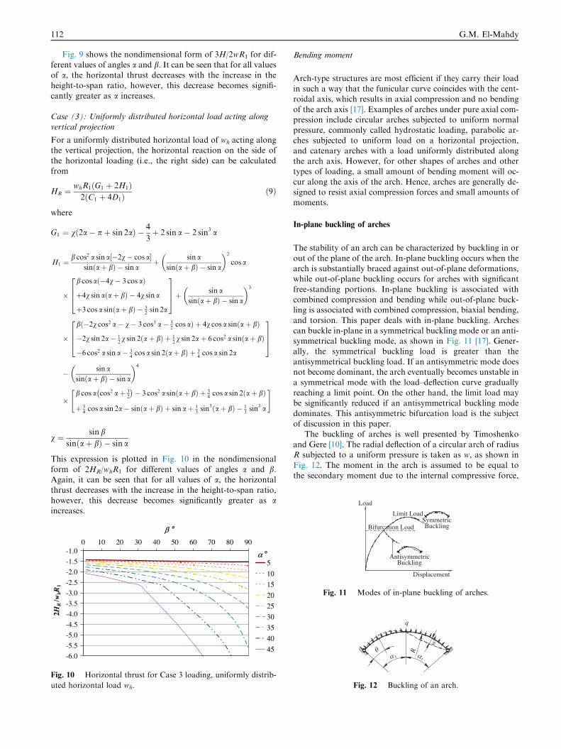
Fig. 9 shows the nondimensional form of 3H/2wR1 for dif-ferent values of angles a and b. It can be seen that for all valuesof a, the horizontal thrust decreases with the increase in the
height-to-span ratio, however, this decrease becomes signifi-cantly greater as a increases.
Case (3): Uniformly distributed horizontal load acting alongvertical projection
For a uniformly distributed horizontal load of wh acting alongthe vertical projection, the horizontal reaction on the side of
the horizontal loading (i.e., the right side) can be calculatedfrom
HR ¼whR1ðG1 þ 2H1Þ2ðC1 þ 4D1Þ
ð9Þ
where
G1 ¼ vð2a� pþ sin 2aÞ � 4
3þ 2 sin a� 2 sin3 a
H1 ¼b cos2 a sin a½�2v� cos a�
sinðaþ bÞ � sin aþ sin a
sinðaþ bÞ � sin a
� �2
cos a
�
b cos að�4v� 3 cos aÞ
þ4v sin aðaþ bÞ � 4v sin a
þ3 cos a sinðaþ bÞ � 32sin 2a
2664
3775þ sin a
sinðaþ bÞ � sin a
� �3
�
bð�2v cos2 a� v� 3 cos3 a� 32cos aÞ þ 4v cos a sinðaþ bÞ
�2v sin 2a� 12v sin 2ðaþ bÞ þ 1
2v sin 2aþ 6 cos2 a sinðaþ bÞ
�6 cos2 a sin a� 34cos a sin 2ðaþ bÞ þ 3
4cos a sin 2a
2664
3775
� sin asinðaþ bÞ � sin a
� �4
�b cos a cos2 aþ 3
2
� �� 3 cos2 a sinðaþ bÞ þ 3
4cos a sin 2ðaþ bÞ
þ 34cos a sin 2a� sinðaþ bÞ þ sin aþ 1
3sin3ðaþ bÞ � 1
3sin3 a
" #
v ¼ sin bsinðaþ bÞ � sin a
This expression is plotted in Fig. 10 in the nondimensional
form of 2HR/whR1 for different values of angles a and b.Again, it can be seen that for all values of a, the horizontalthrust decreases with the increase in the height-to-span ratio,
however, this decrease becomes significantly greater as aincreases.
-6.0
-5.5
-5.0
-4.5
-4.0
-3.5
-3.0
-2.5
-2.0
-1.5
-1.00 10 20 30 40 50 60 70 80 90
β o
2 HR
/ whR
1
51015202530354045
α o
Fig. 10 Horizontal thrust for Case 3 loading, uniformly distrib-
uted horizontal load wh.
Bending moment
Arch-type structures are most efficient if they carry their loadin such a way that the funicular curve coincides with the cent-roidal axis, which results in axial compression and no bending
of the arch axis [17]. Examples of arches under pure axial com-pression include circular arches subjected to uniform normalpressure, commonly called hydrostatic loading, parabolic ar-ches subjected to uniform load on a horizontal projection,
and catenary arches with a load uniformly distributed alongthe arch axis. However, for other shapes of arches and othertypes of loading, a small amount of bending moment will oc-
cur along the axis of the arch. Hence, arches are generally de-signed to resist axial compression forces and small amounts ofmoments.
In-plane buckling of arches
The stability of an arch can be characterized by buckling in or
out of the plane of the arch. In-plane buckling occurs when thearch is substantially braced against out-of-plane deformations,while out-of-plane buckling occurs for arches with significant
free-standing portions. In-plane buckling is associated withcombined compression and bending while out-of-plane buck-ling is associated with combined compression, biaxial bending,and torsion. This paper deals with in-plane buckling. Arches
can buckle in-plane in a symmetrical buckling mode or an anti-symmetrical buckling mode, as shown in Fig. 11 [17]. Gener-ally, the symmetrical buckling load is greater than the
antisymmetrical buckling load. If an antisymmetric mode doesnot become dominant, the arch eventually becomes unstable ina symmetrical mode with the load–deflection curve gradually
reaching a limit point. On the other hand, the limit load maybe significantly reduced if an antisymmetrical buckling modedominates. This antisymmetric bifurcation load is the subjectof discussion in this paper.
The buckling of arches is well presented by Timoshenkoand Gere [10]. The radial deflection of a circular arch of radiusR subjected to a uniform pressure is taken as w, as shown in
Fig. 12. The moment in the arch is assumed to be equal tothe secondary moment due to the internal compressive force,
SymmetricBuckling
AntisymmetricBuckling
Displacement
Bifurcation Load
Fig. 11 Modes of in-plane buckling of arches.
q
R
1 1
w
Fig. 12 Buckling of an arch.

Parametric study of the structural and in-plane buckling analysis of ogee arches 113
S, multiplied by the deflection w (i.e., M = Sw). Hence, thedifferential equation for the buckling of the arch is
d2w
dh2þ w ¼ �R2Sw
EIð10Þ
where S= qR, q being the uniform pressure acting on thearch, and EI is the bending rigidity of the arch. In this equationthe variation of the compressive force S along the length of the
arch is neglected. Taking k2 = 1 + qR3/EI the differentialequation for the buckling of the circular arch is
d2w
dh2þ k2w ¼ 0 ð11Þ
The general solution of this equation is w = A sin kh + B cos
kh. Satisfying the condition at the left end (h = 0) gives B = 0,and the condition at the right end (h = 2a1) gives sin 2a1k = 0.The smallest root for this that satisfies the condition of inex-
tensibility of the center line of the arch is k = p/a1 giving
qcr ¼EI
R3
p2
a21
� 1
� �ð12Þ
Eq. (12) is a good approximation for the case of a uni-formly distributed vertical load. Austin [8] noted that the crit-
ical thrust for the case of a two-hinged circular arch withmidspan concentrated load in which large bending momentand displacements exist prior to buckling is nearly the same
as the critical thrust for the uniform pressure loading whichcauses only compression in the arch. So, it can be assumed thatthe buckling data for arches subjected to loadings which cause
pure compression can be used to estimate the critical loadingvalues for other symmetrical loadings.
Finite element analysis
COSMOS/M 2.6, a finite element program, was used to modelthe ogee arches. The finite element model consisted of 2Delastic straight beam elements along the axis of the arch. The
Table 1 Specimens used in parametric study.
Specimen Angle a� h/R1 Angle b� R2/R1
S1 0 1.000 0.0 0.000
S2 5 1.005 1.6 3.137
S3 5 1.050 53.4 0.114
S4 5 1.080 77.8 0.096
S5 5 1.100 90.0 0.096
S6 10 1.020 2.9 3.501
S7 10 1.100 47.2 0.260
S8 10 1.150 67.2 0.217
S9 10 1.200 82.2 0.210
S10 15 1.038 1.2 12.828
S11 15 1.100 24.8 0.679
S12 15 1.200 54.3 0.383
S13 15 1.300 74.5 0.349
S14 20 1.068 1.2 17.442
S15 20 1.100 10.3 2.104
S16 20 1.200 34.6 0.723
S17 20 1.300 53.0 0.557
S18 20 1.400 66.8 0.521
S19 25 1.110 1.4 19.200
S20 25 1.200 19.6 1.512
S21 25 1.300 36.0 0.935
number of nodes varied from model to model, but in generalthe beam elements were modeled to subtend an angle ofapproximately 10�. The beam elements were modeled using
the properties of steel giving the material model a modulusof elasticity of 210 GPa and a yield stress of 350 MPa. Themodel was given a cross-sectional area of 8450 mm2 and a mo-
ment of inertia of 0.231 · 109 mm4. The model was constrainedat the base of the arch in both planar directions to achieve thepinned-end conditions. Initially, a linear analysis was con-
ducted to verify the horizontal reactions derived previouslyand to obtain the bending moment diagram. Then an eigen-value buckling analysis was conducted to find the trend in elas-tic buckling for each case of loading. A nonlinear analysis was
conducted to verify these elastic buckling loads. As the ogeearches are not shallow arches, a snapthrough analysis wasnot conducted.
The parametric study consisted of 42 specimens with anglesa ranging from 0� to 45� and h/R1 ratios ranging from 1 to 2.The corresponding values of angle b and ratio R2/R1 were
determined from Eqs. (3)–(5). These specimens represent ogeearches of practical proportions with various heights and curva-tures. The lower bound of these specimens, S1, was a semi-cir-
cular arch with a = 0o and h/R1 equal to 1. This specimen isused to compare the finite element results with the theoreticalbuckling results and also represents the upper limit for thebifurcation buckling loads of the ogee arches. Table 1 lists
the specimens used in the parametric study.
Results and discussion
Linear analysis
The linear analysis was used to verify the horizontal thrustreactions expressed in Eqs. (7)–(9) and are shown in Figs. 8–10to obtain the bending moment diagrams. The finite element
horizontal thrust compared accurately with the analyticalvalues derived with a deviation of less than 0.5% for Case 1
Specimen Angle a� h/R1 Angle b� R2/R1
S22 25 1.400 48.9 0.785
S23 30 1.165 1.8 18.545
S24 30 1.200 7.5 4.597
S25 30 1.300 22.0 1.735
S26 30 1.400 33.8 1.258
S27 30 1.700 58.2 1.000
S28 35 1.230 1.3 31.097
S29 35 1.350 15.6 2.879
S30 35 1.400 20.8 2.261
S31 35 1.600 37.5 1.508
S32 35 1.800 49.4 1.360
S33 35 2.000 58.2 1.350
S34 40 1.320 1.6 30.388
S35 40 1.400 9.3 5.569
S36 40 1.600 24.8 2.452
S37 40 1.800 36.3 1.954
S38 40 2.000 45.0 1.818
S39 45 1.430 1.3 44.570
S40 45 1.600 13.3 4.918
S41 45 1.800 24.2 3.105
S42 45 2.000 32.7 2.618

Fig. 13 Deflected shape and bending moment diagram for the three cases of loading.
Fig. 14 Antisymmetrical buckling mode of arch.
114 G.M. El-Mahdy
loading, less than 0.3% for Case 2 loading, and less than 5%for Case 3 loading. The deformed shape and bending momentsfor the three cases of loading are shown in Fig. 13a–c. As the
ogee curve is not the funicular curve for any of these cases ofloading, there is a fair amount of bending moment produced,which must be taken into consideration in the design of such
arches.
Eigenvalue buckling analysis
The critical value of the uniform pressure, qcr, is 3EI/R3 inaccordance with the theoretical results for a two-hinged semi-circular arch (a1 = p/2) are subjected to uniform pressure asgiven in Eq. (12). Using the finite element method to perform
an eigenvalue buckling analysis the bifurcation uniform pres-sure was found to equal 3.27EI/R3 for a two-hinged uniformlycompressed circular arch with a constant cross section. Fur-
thermore, the bifurcation load was found to equal 3.50EI/R3
for a two-hinged circular arch with a constant cross sectionand loaded by a uniformly distributed vertical load acting
along the horizontal projection (i.e., live load), and 2.62EI/R3 for a two-hinged circular arch with constant cross sectionand loaded by a uniform vertical pressure acting along the axis
of the arch (i.e., dead load). Hence, the finite element bucklinganalysis compares relatively well with the theoretical values.The bifurcation buckling mode is antisymmetrical as shownin Fig. 14.
Nonlinear analysis
To verify the bifurcation loads obtained from the bucklinganalysis, a nonlinear analysis was conducted with an initialgeometric imperfection. The arch was modeled with an initial
horizontal imperfection at the peak of the arch and the loadwas applied incrementally using elastic material propertiesand large deformation. The load converged with the bifurca-
tion load in an antisymmetrical deformation mode whichtended to push the arch in the opposite direction to the initialimperfection. Fig. 15 shows a typical nonlinear load – horizon-

0.0
0.5
1.0
1.5
2.0
2.5
3.0
3.5
4.0
-20 0 20 40 60 80Peak Horizontal Displacement (cm)
wR
13 / EI Nonlinear Path
Bifurcation Load
Fig. 15 Nonlinear load – horizontal displacement curve.
1.2
1.4
1.6
1.8
2.0
2.2
2.4
2.6
2.8
1.0 1.2 1.4 1.6 1.8 2.0h/R1
wcr
R3 / E
I
α=0α=5α=10α=15α=20α=25α=30α=35α=40α=45
Fig. 17 Buckling load for uniformly distributed vertical load
acting along the axis of the arch.
Parametric study of the structural and in-plane buckling analysis of ogee arches 115
tal displacement curve for specimen S17 with a uniform verti-
cal load acting along the horizontal projection. The nonlinearanalysis indicates a little imperfection sensitivity by showing aslight decrease in the convergence load from the bifurcationbuckling load.
Effect of height-to-base radius ratio
The parametric ogee arch analysis shows that the bifurcation
buckling load for the case of a concentrated load at midspandepends only on the ratio of the height of the arch to the radiusof the base of the arch (h/R1). This value can be expressed in a
nondimensional form using PcrR12/EI such that the expression
PcrR21
EI¼ �2:84 h
R1
þ 8:94 ð13Þ
gives a good lower bound solution for this case as shown inFig. 16. The objective of using a nondimensional form is toeliminate the size of the arch, the material properties, and
the cross-sectional inertia from the results. In this way thebuckling values or Eq. (13) can be used to find the bucklingload of any arch size with any cross section or material
properties.For the case of uniformly distributed vertical load acting
along the axis of the arch, representing the dead load, the para-metric ogee arch analysis shows that the buckling load again
depends only on the ratio of the height of the arch to the radiusof the base of the arch (h/R1). This value can be expressed in anondimensional form using wcrR1
3/EI such that the expression
3.0
3.5
4.0
4.5
5.0
5.5
6.0
6.5
1.0 1.2 1.4 1.6 1.8 2.0h/R1
Pcr
R2 / E
I
α=0α=5α=10α=15α=20α=25α=30α=35α=40α=45
Fig. 16 Buckling load for concentrated load at midspan.
wcrR31
EI¼ �1:28 h
R1
þ 3:87 ð14Þ
gives a good lower bound solution for this case as shown inFig. 17.
The live load distribution is best represented by a uniformly
distributed vertical load acting along the horizontal projection.In this case the parametric ogee arch analysis shows that thebuckling load again depends on the ratio of the height of the
arch to the radius of the base of the arch (h/R1) but the rela-tionship is not quite linear and the results show a fair amountof scatter. Fig. 18 shows that the lower bound solution for thecritical load for this case can be expressed as
wcrR31
EI¼ �0:57 h
R1
þ 4:06 ð15Þ
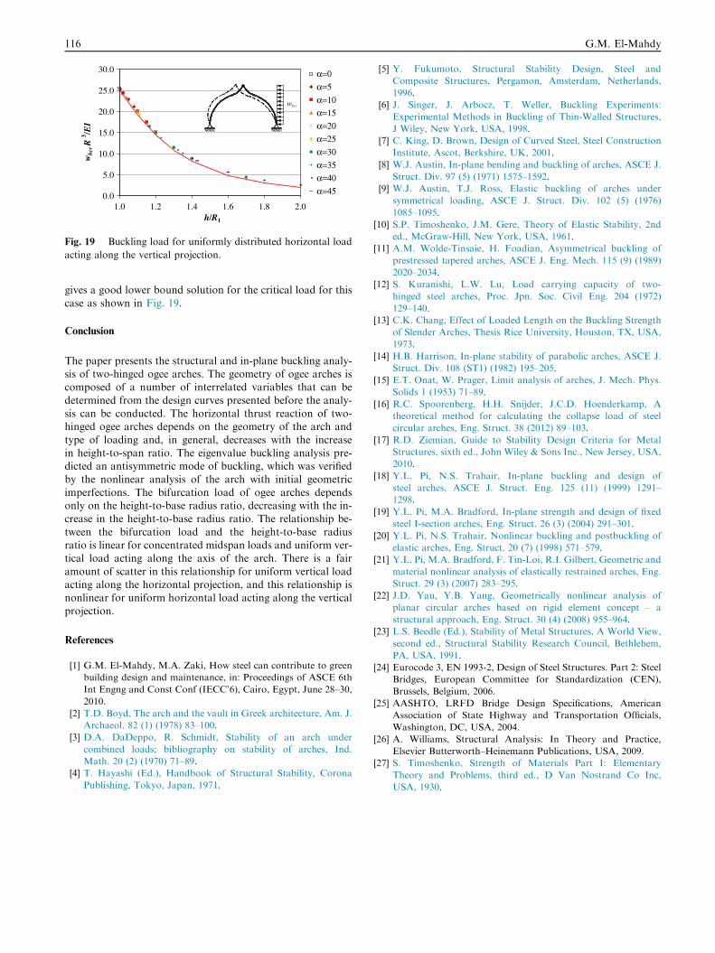
Finally, for the horizontal distributed load acting along thevertical projection which represents wind load, the parametricogee arch analysis shows that the buckling load again depends
only on the ratio of the height of the arch to the radius of thebase of the arch (h/R1), but for this case of loading the rela-tionship is nonlinear. The value of the bifurcation bucklingload can be expressed in a nondimensional form using
whcrR13/EI such that the expression
whcrR31
EI¼ �26:9 h
R1
� �3
þ 150:3h
R1
� �2
� 285:8h
R1
þ 187:5
ð16Þ
2.9
3.0
3.1
3.2
3.3
3.4
3.5
3.6
1.0 1.2 1.4 1.6 1.8 2.0h/R1
wcr
R3 / E
I
α=0α=5α=10α=15α=20α=25α=30α=35α=40α=45
Fig. 18 Buckling load for uniformly distributed vertical load
acting along the horizontal projection.
0.0
5.0
10.0
15.0
20.0
25.0
30.0
1.0 1.2 1.4 1.6 1.8 2.0h/R1
whc
r R
3 / EI
α=0α=5α=10α=15α=20α=25α=30α=35α=40α=45
Fig. 19 Buckling load for uniformly distributed horizontal load
acting along the vertical projection.
116 G.M. El-Mahdy
gives a good lower bound solution for the critical load for this
case as shown in Fig. 19.
Conclusion
The paper presents the structural and in-plane buckling analy-sis of two-hinged ogee arches. The geometry of ogee arches iscomposed of a number of interrelated variables that can be
determined from the design curves presented before the analy-sis can be conducted. The horizontal thrust reaction of two-hinged ogee arches depends on the geometry of the arch and
type of loading and, in general, decreases with the increasein height-to-span ratio. The eigenvalue buckling analysis pre-dicted an antisymmetric mode of buckling, which was verifiedby the nonlinear analysis of the arch with initial geometric
imperfections. The bifurcation load of ogee arches dependsonly on the height-to-base radius ratio, decreasing with the in-crease in the height-to-base radius ratio. The relationship be-
tween the bifurcation load and the height-to-base radiusratio is linear for concentrated midspan loads and uniform ver-tical load acting along the axis of the arch. There is a fair
amount of scatter in this relationship for uniform vertical loadacting along the horizontal projection, and this relationship isnonlinear for uniform horizontal load acting along the vertical
projection.
References
[1] G.M. El-Mahdy, M.A. Zaki, How steel can contribute to green
building design and maintenance, in: Proceedings of ASCE 6th
Int Engng and Const Conf (IECC’6), Cairo, Egypt, June 28–30,
2010.
[2] T.D. Boyd, The arch and the vault in Greek architecture, Am. J.
Archaeol. 82 (1) (1978) 83–100.
[3] D.A. DaDeppo, R. Schmidt, Stability of an arch under
combined loads; bibliography on stability of arches, Ind.
Math. 20 (2) (1970) 71–89.
[4] T. Hayashi (Ed.), Handbook of Structural Stability, Corona
Publishing, Tokyo, Japan, 1971.
[5] Y. Fukumoto, Structural Stability Design, Steel and
Composite Structures, Pergamon, Amsterdam, Netherlands,
1996.
[6] J. Singer, J. Arbocz, T. Weller, Buckling Experiments:
Experimental Methods in Buckling of Thin-Walled Structures,
J Wiley, New York, USA, 1998.
[7] C. King, D. Brown, Design of Curved Steel, Steel Construction
Institute, Ascot, Berkshire, UK, 2001.
[8] W.J. Austin, In-plane bending and buckling of arches, ASCE J.
Struct. Div. 97 (5) (1971) 1575–1592.
[9] W.J. Austin, T.J. Ross, Elastic buckling of arches under
symmetrical loading, ASCE J. Struct. Div. 102 (5) (1976)
1085–1095.
[10] S.P. Timoshenko, J.M. Gere, Theory of Elastic Stability, 2nd
ed., McGraw-Hill, New York, USA, 1961.
[11] A.M. Wolde-Tinsaie, H. Foadian, Asymmetrical buckling of
prestressed tapered arches, ASCE J. Eng. Mech. 115 (9) (1989)
2020–2034.
[12] S. Kuranishi, L.W. Lu, Load carrying capacity of two-
hinged steel arches, Proc. Jpn. Soc. Civil Eng. 204 (1972)
129–140.
[13] C.K. Chang, Effect of Loaded Length on the Buckling Strength
of Slender Arches, Thesis Rice University, Houston, TX, USA,
1973.
[14] H.B. Harrison, In-plane stability of parabolic arches, ASCE J.
Struct. Div. 108 (ST1) (1982) 195–205.
[15] E.T. Onat, W. Prager, Limit analysis of arches, J. Mech. Phys.
Solids 1 (1953) 71–89.
[16] R.C. Spoorenberg, H.H. Snijder, J.C.D. Hoenderkamp, A
theoretical method for calculating the collapse load of steel
circular arches, Eng. Struct. 38 (2012) 89–103.
[17] R.D. Ziemian, Guide to Stability Design Criteria for Metal
Structures, sixth ed., John Wiley & Sons Inc., New Jersey, USA,
2010.
[18] Y.L. Pi, N.S. Trahair, In-plane buckling and design of
steel arches, ASCE J. Struct. Eng. 125 (11) (1999) 1291–
1298.
[19] Y.L. Pi, M.A. Bradford, In-plane strength and design of fixed
steel I-section arches, Eng. Struct. 26 (3) (2004) 291–301.
[20] Y.L. Pi, N.S. Trahair, Nonlinear buckling and postbuckling of
elastic arches, Eng. Struct. 20 (7) (1998) 571–579.
[21] Y.L. Pi, M.A. Bradford, F. Tin-Loi, R.I. Gilbert, Geometric and
material nonlinear analysis of elastically restrained arches, Eng.
Struct. 29 (3) (2007) 283–295.
[22] J.D. Yau, Y.B. Yang, Geometrically nonlinear analysis of
planar circular arches based on rigid element concept – a
structural approach, Eng. Struct. 30 (4) (2008) 955–964.
[23] L.S. Beedle (Ed.), Stability of Metal Structures, A World View,
second ed., Structural Stability Research Council, Bethlehem,
PA, USA, 1991.
[24] Eurocode 3, EN 1993-2, Design of Steel Structures. Part 2: Steel
Bridges, European Committee for Standardization (CEN),
Brussels, Belgium, 2006.
[25] AASHTO, LRFD Bridge Design Specifications, American
Association of State Highway and Transportation Officials,
Washington, DC, USA, 2004.
[26] A. Williams, Structural Analysis: In Theory and Practice,
Elsevier Butterworth–Heinemann Publications, USA, 2009.
[27] S. Timoshenko, Strength of Materials Part I: Elementary
Theory and Problems, third ed., D Van Nostrand Co Inc,
USA, 1930.