Embed Size (px)
DESCRIPTION
Paramount
Citation preview

Robert E. Englekirk, Ph.D., P.E., S.E.Consulting Structural EngineerEnglekirk Systems Development, Inc.Los Angeles, CaliforniaAlso, Adjunct Professor University of California at San Diego
At 39 stories and 420 ft (128 m) high, The Paramount (located in SanFrancisco, California) is the tallest concrete structure in addition tobeing the tallest precast, prestressed concrete framed building inSeismic Zone 4 (a double record). It is the first major high risebuilding to be braced by an architecturally finished exposed precastconcrete ductile frame. The reinforcement used to create this seismicductile frame includes post-tensioning and high strength reinforcingsteel. All this represents a major milestone in the development ofprecast/prestressed concrete. The building is basically an apartmentcomplex, although the lower floors accommodate retail space, vehicleparking and recreational amenities. This article presents the designconsiderations, construction highlights, research and development,and code approval process that led to the realization of this structure.
Soaring majestically amidst theother high-rise buildings in SanFrancisco is The Paramount —
a 39-story residential apartment towerthat reaches 420 ft (128 m) skyward(see Fig. 1). Costing nearly $93 mil-lion, the newly constructed building isprestigiously located at Third andMission across from the famousMoscone Center, further enriching thecity’s world renowned skyline.
What distinguishes this buildingfrom the other highrises surrounding itis that the structure incorporates a
novel precast hybrid moment resistingframe that is particularly effective inthe severest seismic regions of theUnited States and indeed the world.As such, The Paramount is not onlythe tallest concrete structure built inSeismic Zone 4, but it is also by farthe tallest precast, prestressed concreteframed structure built in a region ofhigh seismicity.
From a precast concrete perspective,it is the first major high rise buildingto be braced by an architecturally fin-ished exposed concrete ductile frame.
Design-Construction of The Paramount – A 39-StoryPrecast Prestressed ConcreteApartment Building
56 PCI JOURNAL
HARRY H. EDWARDS AWARD WINNER
Long-time PCI Professional Mem-ber Robert E. Englekirk has been astrong advocate of precast concreteconstruction for many years. A PCIFellow, he is the author of numeroustechnical articles, three of which havewon the Martin P. Korn, Robert J.Lyman and Charles C. Zollman PCIJOURNAL Awards. He has just com-pleted a book titled “Seismic Designof Concrete and Precast ConcreteStructures to a Performance Crite-rion,” which will be published byJohn Wiley & Sons in early 2003.

The reinforcement used to create thisductile frame includes both post-ten-sioning strand and high strength mildsteel reinforcing with a yield strengthof 120 ksi (8280 MPa). This combina-tion of materials also represents a sig-nificant technological breakthrough.
The accomplishment of these mile-stones is a credit to the courage andperserverance of the design-construc-tion team:
• Owner: Third and Mission Associ-ates, Inc. – For courageously accept-ing a concrete high rise buildingwith a brand new structural bracingsystem in a very severe seismicarea.
• Architects: Kwan Henmi, Architec-ture and Planning, and Elkus/Man-fredi Architects, Ltd. – For veryimaginatively integrating the struc-tural framing system into the archi-
tectural design, and thereby creatinga very functional and beautifulbuilding.
• Structural Engineers: Robert En-glekirk Consulting Structural Engi-neers, Inc. – For pioneering thestructural engineering concept anddeveloping the details of the bracingsystem for this building.
• Contractor: Pankow ResidentialBuilders II, Ltd. – For enthusiasti-
July-August 2002 57
Fig. 1. The Paramountat Third and Mission,San Francisco,California. Photo courtesy: Kwan Henmi,Architecture andPlanning.

58 PCI JOURNAL
cally embracing the seismic bracingsystem and sponsoring the neces-sary research to test the system atthe University of Washington.How the design-construction team
realized their dream is the subject ofthis paper.
SYSTEM SELECTIONThe obvious first question to ask is,
why, in such a pedantic industry,would any one of the team memberselect to follow such a difficult road?New systems are only developed whenit is clear that they will be less expen-sive and better than the standard theypropose to replace. The author is notsure whether the “better” is essential,but in this project, both conditionswere in fact met.
Economies in construction are pro-duced by an efficient use of materialsand/or reducing the time required todeliver an occupiable building. TheParamount team fulfilled both of theseparameters. Fig. 2 shows an artist’srendering of the project, while Figs. 3and 4 show a plan and elevation, re-spectively, of the building.
Two expensive building compo-nents, namely, the architecturalcladding and the seismic bracing sys-
Fig. 2. Artist’s rendering of The Paramount. Photo courtesy: Kwan Henmi,Architecture and Planning. Artist: W. Yeliseyev.
Fig. 3. Typical planof building.

July-August 2002 59
tem, were efficiently combined on thisproject. This not only resulted in lowerconstruction costs, but also produced amore water resistant exterior, an espe-cially important benefit in San Fran-cisco. When the exterior water barrieris applied to the frame of a buildinglocated in a seismically active area, itmust be designed to accept the move-ment expected during an earthquake.
This means that slip joints must beintroduced that can accommodate dif-ferential displacements of as much as21/2 in. (64 mm). This is usually ac-complished with the introduction oflarge caulked joints which, in additionto being expensive, require significantmaintenance.
The construction of the Paramountexterior avoids this problem, becausethe precast components are rigidly at-tached to each other and designed sothat the pieces move together. Further,the beams are post-tensioned to 760
EL. +520’–6 5/8”PENTHOUSE ROOF
EL. +212’–11 1/2”FLOOR 10
EL. +165’–7”FLOOR 5
EL. +136’–7”P1
EL. +121’–7”FLOOR 2
EL. +155’–11”P3
EL. +212’–1”PH ROOF (T.O.S.)
EL. +175’–3”P5
EL. +257’–4”FLOOR 15
EL. +302’–6”FLOOR 20
EL. +347’–8”FLOOR 25
EL. +392’–0 1/2”FLOOR 30
EL. +439’–5”FLOOR 35
EL. +487’–1”FLOOR 40 MECH.
EL. +511’–1”ELEV. MACH. RM
BUILDING FACILITIESThe building contains 486 apart-
ment units comprising a total of660,000 sq ft (61380 m2) area ofrentable space. The lower eightfloors and one basement level ac-commodate a variety of functionswithin a floor area of 31,000 sq ft(2880 m2). Retail space occupiesmost of the first and second floors.Residential amenities include aleasing office and business centeron the third floor with a fitnesscenter and outdoor swimming poolon the fourth floor.
Floors 3 to 7 of the north side ofthe building accommodate parkingfor 350 vehicles, including an all-valet parking station served by ele-vators instead of ramps. Residen-tial units are located on the southside of the building at the fourththrough seventh floors.
The eighth floor serves as apodium for the typical 13,700 sq ft(1274 m2) residential floors aboveon Floors 9 through 33. The build-ing steps back at the 34th floor to a9900 sq ft (920 m2) floor for Floors34 through 39. Level 40 is an out-door recreation deck area. Fig. 4. Elevation of building showing heights of various floors. Drawing courtesy:
Kwan Henmi, Architecture and Planning.
ELEVATION
EL. +195’–2 1/2”FLOOR 8

60 PCI JOURNAL
psi (5.2 MPa) and the columns are, ofcourse, always subjected to high com-pressive stresses.
The result is a watertight enclosure.An added level of protection is pro-vided by caulking the beam-to-columnjoints. Because the joints are small[about 3/4 in. (19 mm)], and are alwaysprestressed, maintenance should beminimal.
The façade of the building consistsof 732 sandblasted precast beams and478 two-story precast moment framecolumns. In addition to the framemembers, 641 architectural precastpanels, 68 precast gravity columns,and 312 precast, prestressed beamswere fabricated off-site. By using suchan extensive quantity of precast com-ponents, the construction schedulewas significantly expedited.
The fact that the structural systemprovided was superior from a seismicperspective was easily (and often)demonstrated to the developer, in-vestors, lenders, and insurers by show-ing them the post-test conditions oftested models. Fig. 5 illustrates thecondition of a cast-in-place beam (seeFig. 5a) after it was subjected to earth-quake-like deformations, while Fig.5b shows the post-test condition of aprecast frame subjected to similar de-formations.
The improved structural behavior isa characteristic of the manner in whichprecast concrete members are assem-bled. Fig. 6 shows how the beam andcolumn interact during an earthquake.In essence, they must rotate so as toallow the building to sway and with-stand the shock of the earthquake. In
the precast system, this is accom-plished by opening a gap (θ) betweenthe beam and column.
In the cast-in-place system, this gapdistributes itself over a finite regionand causes the outer shell of the con-crete to spall (see Fig. 5a). Demon-strating the improved behavior of theprecast system and the basis for itmade the system an easy sell to the de-sign-construction team, its financialbackers, and the building officials.
The final building system was theresult of many design iterations thatconsidered both functional, aestheticand construction needs. The floorplan for the typical floors (up to Floor34), as well as the setbacks requiredof Floors 35 through 39, is shown inFig. 3. The entire perimeter of everytower floor including the setbacksconsists of precast concrete spandrelbeams and two-story precast concretecolumns. The floor was cast-in-placepost-tensioned concrete stressedthrough the top of the slab along thesouth edge where the slab span isshort.
Two types of structural lateral forceresisting systems are utilized in thebuilding. Below the eighth floorpodium, the varying slab elevationsand the required occupancy separa-tions between parking and livingspaces created a natural location forshear walls. Consequently, a shearwall system and a precast and cast-in-place moment frame bracing system
(a) Cast-in-place beam (b) Precast beam-column frame
Fig. 5. Post-test condition of cast-in-place beam and precast ductile beam-column frame.
Fig. 6. Seismicinduced movement
(exaggerated) ofprecast framecomponents.
Reinforcement

July-August 2002 61
was implemented from the mat foun-dation to the eighth floor. The shearwalls terminate at the eighth floor.
Above the eighth floor, a perimeterprecast moment frame was developedusing both the Precast Hybrid MomentResistance Frame (PHMRF) Systemand the Dywidag Ductile Connector(DDC) System®. The PHMRF systemis the predominant frame system uti-lized for the multi-bay frames. TheDDC System was used at single-bayframes that occur at re-entrant cornersof the building where the effectivepost-tensioning force required by thePHMRF could not be developed.
Fig. 7 is a schematic of the post-ten-sioning anchorage details for an exte-rior column, while Fig. 8 shows the re-inforcing cage of a precast column.The newly developed DDC reinforcedframe beam is shown in Fig. 9. A typi-cal corner column detail is shown inFig. 10. Fig. 11 shows the post-ten-sioning jacking operation.
Typical frame columns are 36 in.(914 mm) square up to the 20th leveland reduce to as small as 24 x 36 in.(610 x 914 mm) above. Frame beamsare typically 24 x 36 in. (610 x 914mm) and were set flush to the outsideface of the columns.
THE DESIGN PROCESSNeither the building nor any portion
of its seismic system fit within theframework of the existing building
code. The functionally logical bracingprogram for the building included ashear wall base, which extended fromthe foundation to the eighth level, forthis was the top of the parking struc-ture that occupied the north side ofthe building. The precast concreteductile frame braced the buildingabove Level 8.
Since buildings over 160 ft (48.8 m)[now 240 ft (73.1 m)] require the exis-tence of a ductile frame or a dual sys-
tem (shear wall plus ductile frame), anexception was necessary to allow astacked bracing system-frame on topof the shear wall. The Hybrid System,which provided the bulk of the lateralsupport, had yet to be approved, whilethe DDC® System represented a modi-fication of the precast system ap-proved by the International Confer-ence of Building Officials (ICBO).1
Accordingly, the project lacked awell-defined seismic criterion.
Fig. 7. Reinforcing details of exterior column.
Fig. 8. Reinforcing cage of precast column. Fig. 9. DDC reinforced frame beam.

62 PCI JOURNAL
In some ways, this lack of a specificcriterion was an advantage. This is be-cause building codes should not beused as the exclusive criterion for thedesign of a complex structure. Currentbuilding codes have as their focus theelastic behavior range. In essence, thestructure is designed to a strength cri-terion (Fo) (see Fig. 12).
The design engineer understandsthat the structure will respond whensubjected to a major earthquake in adisplacement range many times thatassociated with the elastic design load(Fo, Δo) (see Fig. 12). The probable re-sponse range is understood to be in thevicinity of Δu (see Fig. 12) and this, ofcourse, should be the region of pri-mary concern to the design engineer.
Current building codes bridge thisdisplacement gap (Δo – Δu) by pre-scriptions intended to cover all eventu-alities. Obviously, it is not possible togenerically cover all possible systemsby prescription. Consequently, con-flicts tend to arise, and this often re-sults in the acceptance of less than op-timal behavior.
The design approach that has as itsfocus the region of behavior interest(see Fig. 12) is now referred to as Per-formance Based Design, and only at-tempts to codify this approach arenew, for many designers including theauthor have used it for 30 years. Theessence of Performance Based Designis to predict member strain states atthe anticipated level of building drift.
Response of Ductile Structure
Fig. 10. Corner column detail. Fig. 11. Jacking operation.
Fig. 12. System behavior idealization.
Fig. 13. Hybrid beam system as developed by NIST.5

July-August 2002 63
Strain objectives or limit states areestablished experimentally, and thelinkage between analysis and compo-nent behavior is established throughthe testing of large-scale models ofmembers and subassemblies. On thisproject, exclusive reliance on a Perfor-mance Based Design approach wasadopted by the design team, althoughthey, of course, were required todemonstrate compliance with the in-tent of the code to obtain a buildingpermit.
PRECAST SEISMIC BRACING SYSTEMS
The combining of precast compo-nents by post-tensioning is not new.Professor Robert Park (University ofChristchurch, New Zealand) and hisassociates tested several post-ten-sioned subassemblies in the 1960s.Clearly, the concept preceded the abil-ity of builders to exploit it, so the ideawas not pursued.
In 1978, the author proposed the de-velopment of a post-tensioned assem-bly and subsequently presented theconcept at several workshops.2-4 H. S.Lew at the National Institute of Stan-dards and Technology (NIST)5 ob-tained a grant to develop what becameknown as the Hybrid System. Ulti-mately, the system described in Fig.13 was produced after a number of it-erations at the NIST test facility.
Unfortunately, this particular modeldid not satisfy the needs of theParamount project because the anglesthat armed the corners of the beams(see Fig. 10) were not acceptable.Also, the concrete strain limit states re-quired to effect a performance basedlimit state were not established as aconsequence of arming the corners.Further, the strength of the beam-to-column joint was not established be-cause the strength of the beam-to-col-umn joint tested significantly exceededthe demand imposed on it.
Additional testing was required todevelop a performance based designcriterion for the Hybrid System, andthis was undertaken at the Universityof Washington. Interior, exterior, andcorner subassemblies were tested. Theattempt was to follow the guidelinescontained in ACI’s proposed accep-
tance criterion.6 The interior test sub-assembly is described in Fig. 14.
This subassembly was modeled soas to represent a two-thirds scalemodel of the frame proposed for theParamount building. The ACI accep-tance criterion required that the sub-assembly be designed prior to testing
Fig. 15. Behavior of Hybrid beam test assembly (see Fig. 14).
Fig. 14. Interior Hybrid beam test assembly.
so as to predict its strength and deflec-tion, as well as the point at which thesubassembly would start losing itsstrength. The subassembly (see Fig.14) was constructed and assembledstrictly following the procedures pro-posed for the project. The experimen-tal model was then subjected to dis-

64 PCI JOURNAL
placements of increasing magnitude,and each displacement was repeatedthree times before proceeding to thenext level of deformation.
Fig. 15 describes the behavior of thetest specimen. The strength that wasattained exceeded that predicted byanalysis. The predicted nominal flexu-ral strength was 90 percent of that ex-perimentally attained, while thestrength predicted for the joint was 83percent of that established by the test.Accordingly, the validity of the designprocess was demonstrated. It is inter-esting to note that a recently proposedconsensus design criterion will allowthe use of only 60 percent of the de-velopable strength.
From a displacement perspective,
the performance of the subassemblyalso exceeded the desired objectives.Normally, in Seismic Zone 4, the sub-assembly is designed to drifts of 2 to2.5 percent. The acceptance criterionlooked into the deformability of thesystem and required that the test pro-gram be able to demonstrate that driftsof 3.5 to 4 percent could be attainedwithout significant loss of strength. Ata drift of 4 percent, the third cycle lossof strength was less than 30 percent,while no loss of strength was experi-enced in the expected drift range (2.5percent), and this was considered ac-ceptable.
For years, the author had studied thebehavior of cast-in-place beams sub-jected to post-yield seismic deforma-
tions in an attempt to predict the be-havior of limit states (see Fig. 5a).About 15 years ago, it occurred to himthat the best approach was to avoid theprincipal causative action responsiblefor the deterioration of the concretedescribed in Fig. 5a.
The high concrete strains imposedon the unconfined shell of the beamdescribed in Fig. 5a are exacerbatedby the tendency of the once over-strained reinforcing bars to buckle out-ward when subjected to compressionloads. It seemed virtually impossibleto prevent this outward displacementof the bar clearly visible in Fig. 5awith confining ties.
The solution seemed so obviousonce it occurred to the author — whynot simply move the yielding elementout of the frame beam and into thecolumn where the yielding bar couldbe recompressed without damagingthe surrounding concrete? This reloca-tion was made possible through thedevelopment of a forged ductile rodwhich could be placed in a column(see Fig. 16a). A high strength bar[120 ksi (8280 MPa)] would then bescrewed into the end of the ductile rod(see Fig. 9). Ultimately, this was thesystem that was used in the Paramountproject.
The ductile rod concept seemed ap-propriate for use in all precast build-ings, so the author worked with Dy-widag Systems International todevelop the precast subassembly de-scribed in Fig. 16b, which was theoriginally proposed short and singlespan solution (locations marked withan asterisk in Fig. 3). The builder wasconcerned, however, that bolt align-ment might become a problem, so heopted to use the system described inFig. 9.
Alignment problems should not beanticipated in the precast system (seeFig. 16b) because 1/2 in. (12.7 mm)tolerances are provided for in the con-nection. During this same period(2000-2001) the DDC System (seeFig. 16b) was used to brace the Holly-wood Highland project, and 6700bolts were placed absent any misalign-ments despite the fact that memberswere assembled in self-stabilizingtowers more than 100 ft (30.5 m) high.
Tests had been performed on a cast-
Fig. 16a. Precast concrete columnshowing forged ductile rods.
Fig. 16b. Precast frame application of forgedductile rods.
Fig. 17. Precast frame application of forget ductile rods.
Forged Ductile Rods

July-August 2002 65
in-place DDC subassembly. These testresults are described in Reference 7. Inthis case, the nominal strength of thesubassembly was maintained througha drift of 6.7 percent [δb = 8 in. (203mm)]. The resulting damage was onlycosmetic (see Fig. 5b).
The DDC system required no addi-tional testing in support of its use onthe Paramount project, and this is be-cause a special product approval hadbeen granted Dywidag Systems Inter-national by the ICBO in the early1990s.1 Note that the ICBO approvalprocess is based on submitted experi-mental and analytical evidence whichsupports the design process, as well asproduction control procedures. The re-sult is a quality assured product anddesign procedure. This approval pro-cess is essential to the responsible ad-vancement of precast concrete, for thedays of closely guarded secret home-made connections are gone forever.
BUILDING DESIGNThe adopted Performance Based
Design required that the probablerange of building displacements bepredicted. This was done through theuse of several analytical procedureswhich have evolved over the last 30years. Response spectrum based pro-cedures are the key conceptual designtool. Once the design has been devel-oped, elastic three-dimensional timehistories are performed.
This process involves modeling the
anticipated ground motion both interms of intensity and characteristics.The result is a number of sets of earth-quake ground motions, which are thenfed into the base of the analytical modelof the building. This process suggeststhe extent of building movement.
In the case of the Paramount apart-ments, the movement is expected to beabout 40 in. (1016 mm) at the roof ifthe design ground motion were tooccur. However, do not rush to the
roof in wild anticipation of an excitingride, for this design earthquake is ex-pected to reoccur at intervals of about500 years!
The analytic testing of the buildingdoes not stop with elastic behaviorpredictions because the anticipatedlevel of ground motion will cause theframe beams to reach the inelastic be-havior range (see Fig. 15). To predictthe extent of post-yield demand on theframe beams, inelastic time history
Fig. 20. Progress view of precast frame erection. Photo courtesy: Kwan Henmi,Architecture and Planning.
Fig. 18. Mockup of architectural precast panel assembly atprecaster’s yard.
Fig. 19. Architectural precast panel assembly installed onbuilding façade.

66 PCI JOURNAL
analyses were performed on the vari-ous bracing frames. The design teamconcluded that post-yield rotationswould be in the 1.0 to 1.2 percentrange, and this is well below the ex-perimentally confirmed limit state of 4percent (see Fig. 15).
Most buildings tend to be rectangularin plan in which one dimension is often2.5 to 3 times the other. This is a char-acteristic of the Paramount apartments.The design of this type of configurationmust consider the torsional response,especially in the post-yield range.
When a building responds to earth-quake excitations that drive it into thepost-yield behavior range, the center ofrigidity will gravitate to the strongerbracing element. For example, theeastern-most frame of the Paramountbuilding would become the torsionalpivot, and thus would cause the westframe to respond in an undesirablemanner from a displacement perspec-tive. Further, any imbalance in strengthwould limit the restoring force.
This concern was mitigated by bal-ancing the strength and stiffness of the
east and west frames in both the elas-tic and post-yield behavior range. Thebalance attained is much more impor-tant than compliance with any pre-scribed strength objective. Thus, it isimportant to ensure that the balancingoperation not reduce the availablelevel of ductility in the weaker frameelement (west frame in this case).
The design of the precast concreteframe systems is fairly straightfor-ward. The design of a frame beam isdescribed in Appendix B.
CONSTRUCTIONHIGHLIGHTS
The fabrication, transportation anderection of the precast concrete com-ponents, together with the overall con-struction operation and schedule, wascarried out by Pankow Builders. Theprecast components were fabricated inCorcoran, California, starting in Jan-uary 2000. They were shipped to theproject site by truck-trailer a distanceof about 200 miles (330 km). In all,2231 precast pieces were produced(see Table 1).
Fig. 18 shows a mockup of an archi-tectural precast panel assembly at theprecasting yard. Fig. 19 shows a viewof the architectural precast façade in-stalled on the building. Figs. 20 and 21show various erection phases of thebuilding. Fig. 22 is a completed viewof the building amidst the other high-rises in San Francisco.
Concrete strengths were specified asfollows:
• 478 Precast Moment FrameColumns [ 3 x 3 x 18 ft ]
• 732 Precast Moment FrameBeams [2 x 3 (12 to 24 ftlong) ]
• 68 Precast Gravity Columns[2 x 2 (40 ft long)]
• 641 Architectural Precast Panels [50 to 100 sq ft each]
• 312 Prestressed Beams [40 ft long (average)]
2231 Total Components
Table 1. Breakdown of precastconcrete components.
Note: 1 ft = 0.3048 m; 1 sq ft = 0.093 m2.
Fig. 21. Erection of precast perimeter frames nearing top of building.Photo Courtesy: Kwan Henmi, Architecture and Planning

July-August 2002 67
• For the columns: 6000 to 8000 psi(41 to 55 MPa).
• For the beams: 5000 psi (34 MPa).Formwork for casting the architec-
tural panels, beams and columns wasprovided by Hamilton Form Com-pany, Inc.
The entire construction comprised a26-month schedule. The foundations ofthe building were started on November15, 2000, and subgrade work was com-pleted in March of 2001.
The superstructure was completed
in 16 months. Erection of the precastcomponents started slowly but, aswork progressed, an average produc-tion rate of 21/2 floors per month wasattained.
A major time benefit was the rapidenclosure of each floor which madepossible the installation of electricaland mechanical accessories as well asother fixtures. This made it possiblefor tenants to occupy the premises byOctober 26, 2001 – less than 2 yearsafter the start of construction.
From the mat foundation to theeighth floor, a cast-in-place momentframe bracing and shear wall systemwas used. This was necessary becauseof the varying slab elevations and non-repetitive elements involved. Abovethe eighth floor, a perimeter precastmoment frame was used.
The floor construction cycle, whichultimately took 5 days, started with theplacement of half of the two-story pre-cast column and ended with the rais-ing of the flying forms by one story.
Fig. 22. Finishedview of TheParamount amidstother high risebuildings in SanFrancisco. Photo courtesy:Kwan Henmi,Architecture andPlanning

68 PCI JOURNAL
These forms were designed to supportthe weight of the precast beams. Mostof the beams were hybrid and, as aconsequence, were connected to thecolumns by a concentric post-tension-ing system together with grouted mildsteel bars.
The precast beams were typicallypost-tensioned by 19 – 0.6 in. (15.2mm) diameter strands. Baumesh wasused to facilitate the assembly of thecolumn cages. Short spans, whose lo-cations are marked by an asterisk inFig. 3, were constructed using Dy-widag Ductile Rods®, which were castin the precast columns, and Thread-bars®, which were turned out of the in-terior couplets and into the ductilerods. Note that precast panels servedas the outside form.
Two tower cranes were used toerect the precast members and relo-cate the flying forms. Despite the pro-totypical nature of the project, thecontractor reported that the erectionand assembly process went verysmoothly, and that noise and pollutionwere very minimal.
One of the few problems thatneeded to be resolved was the cornerconditions where, in the absence of amore viable solution, two exteriorstressing assemblies would need to beplaced. Offset assemblies were testedand proved to be effective. However,they were abandoned in favor of an“around the corner stressing.”
The author developed a piece ofhardware consisting of bent pipe sec-tions, restrained by straps connected toan anchoring angle. The stressing pro-gram involved a significant amount oftesting to ensure that strands could beplaced and stressed without damage.
The adopted program involved se-quentially tensioning the strandgroups in increments from both ends.Columns were connected using SpliceSleeves® (supplied by North AmericaSplice Sleeve), which are capable ofdeveloping the breaking strength ofthe bar.
The total cost of the project was$92.7 million. The precast cost was$8.9 million. Based on gross squarefootage of rentable area, this amountsto $140 per sq ft. This cost figure isfairly good considering the building’slocation and seismic environment.
CONCLUDING REMARKS The construction of this innovative
project flowed smoothly and wascompleted on schedule. The credit forthis achievement lies with the Pankowproject management team. Assemblyprocedures were developed in the pre-casting yard and carefully docu-mented, as were the procedures for en-suring high quality.
An even wider use of precast com-ponents is possible. The floor systems,for example, could have been con-structed using pretopped hollow-coreslabs or double tees. All that is reallyrequired is imagination, teamwork,and careful planning.
From a design perspective, the per-formance and the assembly advantageassociated with the development ofyielding precast concrete frame sys-tems is clear. The emphasis to date,insofar as code development is con-cerned, has been on emulative assem-blies where precast concrete is assem-bled so as to perform as though it werecast-in-place concrete. The codifica-tion process must strive to encouragethe yielding approach and avoid therestrictive provisions that dominatecurrent codes.
This design philosophy is consistentwith the performance objectives of thenext generation of seismic codes. Sucha course is particularly important be-cause the structural systems used onthe Paramount apartment building arejust examples of what can be accom-plished. Hopefully, they will engendera whole new approach to construction.
Precast building assemblies mustcontinue to be explored, and theseshould logically include bearing wallsystems.10,11 Contractors and espe-cially precast contractors must be will-ing to spend the time to explore alter-native systems, for the immediatereturn seems attractive and the futurelooks extremely bright.
EPILOGUE In retrospect, the author finds it hard
to believe that during the span of hisprofessional engineering career, Pre-cast Concrete, as a seismic bracingsystem, has evolved from a prohibitedstructural system to a system of pre-ferred choice. The successful comple-
POST-SCRIPTSince its completion last year,
The Paramount has received manyaccolades from the design commu-nity and visitors from around theworld. In June of this year, a juryof peers judging the 2002 PCI De-sign Awards Program, bestowedupon the structure the Harry H. Ed-wards Industry AdvancementAward. The jury comments wereas follows:
“The successful completion ofthis 39-story precast, prestressedconcrete building brings to fruitionthe culmination of a ten-year re-search effort in which the bestminds developed an innovativeseismic lateral force resisting sys-tem. This structure is a classic ex-ample of combining the knowledgeand wisdom learned fromacademia, engineering, architec-ture and construction in a landmarkproject. The path is now open forothers to apply this technologywith precast/prestressed concretestructures in high seismic areas.”
tion of this building, as well as otherstructures currently under construc-tion, attests to this metamorphosis.Clearly, the curved façade andsculpted finish do not fit the tradi-tional stoic image of structural precastconcrete and attest to the fact thatstructural precast concrete has trulycome of age.
CREDITSOwner: Third and Mission Associates,
Inc., Irvine, CaliforniaArchitect of Record: Kwan Henmi,
Architecture and Planning, SanFrancisco, California
Design Architect: Elkus Manfredi,Boston, Massachusetts
Structural Engineers: Robert En-glekirk Consulting Structural Engi-neers, Inc., Los Angeles, California
General Contractor: Pankow Residen-tial Builders II, Ltd., Altadena, Cali-fornia
Precaster: Mid-State Precast, L.P.,Corcoran, California
July-August 2002 69
1. Englekirk, R. E., “An Innovative Design Solution for PrecastPrestressed Concrete Buildings in High Seismic Zones,” PCIJOURNAL, V. 41, No. 4, July-August 1996, pp. 44-53.
2. Englekirk, R. E., “An Evaluation of the State of the Art in theDesign and Construction of Prefabricated Buildings in Seismi-cally Active Areas of the United States,” Earthquake ResistantReinforced Building Construction, June 1978.
3. Englekirk, R. E., and Selna, L.G., “Criteria for the Design ofPrefabricated Concrete Systems,” ATC Proceedings of aWorkshop on Design of Prefabricated Concrete Buildings forEarthquake Loads, April 27-29, 1981, pp. 639-656.
4. Englekirk, R. E., “Overview of the ATC Seminar on Design ofPrefabricated Concrete Buildings for Earthquake Loads,” PCIJOURNAL, V. 27, No. 1, January-February 1982, pp. 80-96.
5. Cheok, G. S., and Lew, H. S., “Model Precast Concrete Beam-to-Column Connections Subject to Cyclic Loading,” PCIJOURNAL, V. 38, No. 4, July-August 1993, pp. 80-92.
6. ACI Innovative Task Group 1 and Collaborators, “AcceptanceCriteria for Moment Frames Based on Structural Testing andCommentary,” ACI Proposed Provisional Standard (ACI T1.1-XX), American Concrete Institute, Farmington Hills, MI, un-dated.
7. Warcholik, G., and Priestley, M. J. N., “Structural Systems Re-search Project: High Strength Concrete Joints Tests – Series 3,Report No. TR-98/12,” University of California, San Diego,July 1998.
8. Englekirk, R. E., Seismic Design of Concrete and PrecastConcrete Structures to a Performance Criterion, John Wiley& Sons, Inc., New York, NY, 2003.
9. Nawy, E. G., Prestressed Concrete: A Fundamental Approach,Third Edition, Prentice Hall, Upper Saddle River, NJ, 2000.
10. Rahman, A. M., and Restrepo, J. I., “Earthquake Resistant Pre-cast Concrete Buildings: Seismic Performance of CantileverWalls Prestressed Using Unbonded Tendons,” Civil Engineer-ing Research Report No. 2000-5, University of Canterbury,Christchurch, New Zealand, August 2000.
11. Holden, T. J., “A Comparison of the Seismic Performance ofPrecast Wall Construction: Emulation and Hybrid Ap-proaches,” Civil Engineering Research Report No. 2001-4,University of Canterbury, Christchurch, New Zealand, April2001.
12. ACI Committee 318, “Building Code Requirements for Struc-tural Concrete (ACI 318-99),” American Concrete Institute,Farmington Hills, MI, 1999.
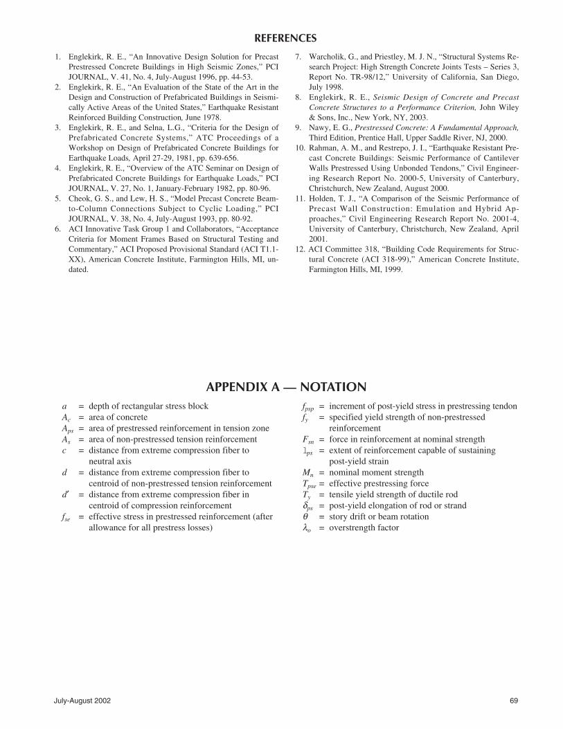
REFERENCES
a = depth of rectangular stress blockAc = area of concreteAps = area of prestressed reinforcement in tension zoneAs = area of non-prestressed tension reinforcementc = distance from extreme compression fiber to
neutral axisd = distance from extreme compression fiber to
centroid of non-prestressed tension reinforcementd′ = distance from extreme compression fiber in
centroid of compression reinforcementfse = effective stress in prestressed reinforcement (after
allowance for all prestress losses)
fpsp = increment of post-yield stress in prestressing tendon fy = specified yield strength of non-prestressed
reinforcementFsn = force in reinforcement at nominal strengthlps = extent of reinforcement capable of sustaining
post-yield strainMn = nominal moment strengthTpse = effective prestressing forceTy = tensile yield strength of ductile rodδps = post-yield elongation of rod or strandθ = story drift or beam rotationλo = overstrength factor
APPENDIX A — NOTATION

70 PCI JOURNAL
The design and analysis of the Hybrid and DDC Systemsis fairly simple. Consider the Hybrid test assembly de-scribed in Fig. B1. These Hybrid beams were reinforcedwith nine 1/2 in. (12.7 mm) diameter, 270 ksi (1862 MPa)strands (concentric unbonded post-tensioning) and three No.6 (Grade 60) mild steel reinforcing bars bonded in the topand bottom of the beam. The grouted interface is 16 in. wideand 20 in. deep (406 x 610 mm). The nominal flexuralstrength is developed from the effective force in the strandand the yield strength of the mild reinforcing steel.
The following properties of materials are assumed:
= 3172 kip-in. (358 kN-m)
The resultant column shear would be:
Two important design objectives are to:1. Provide a restoring force in the post-tensioning strand
that exceeds that which is developed by the mild reinforcingsteel. This will tend to restore the frame to its original pre-earthquake position (Δ ≅ 0).
Mnps > Mns
1865 > 1307 kip-in. (148 kN-m)
2. Furnish a post-tensioning force on the order of 700 to1000 psi (4.83 to 6.90 MPa).
By achieving these two design objectives, it becomes easyto develop an initial frame beam size.
Post-yield strain states in the prestressing strands can alsobe easily checked. Assume that one wants to check thestrand strain state at a subassembly drift of 2 percent.
Start by assuming a neutral axis depth of 5 in. (127 mm).The neutral axis depth must consider the additional strengthprovided by the strand elongation and, depending on the ex-tent of the rotation, the strain hardening in the mild steel.Consider the rotation described in Fig. B2.
T
Ase
c
=
=
223
16(20)
ksi (4.83 MPa)0 7.
V
M
hcol
nb
bc
x
=
⎛⎝⎜
⎞⎠⎟
=
⎛⎝
⎞⎠
=
2
2 317272
62117 5
62 7
l
l
( )
.. kips (279 kN)
A
f
T A f
A
F A f
aT
f b
M Th a
F d d
ps
se
se ps se
s
sn s y
pse
c
n se sn
=
==
=
==
=
=′
=
=
= −⎛⎝
⎞⎠ + −
= −⎛⎝
⎞⎠ +
=
1.38 sq in. (890 mm
162 ksi (1117 MPa)
223 kips (1032 kN)
1.32sq in. (852 mm
79.2 kips (352 kN)
.
223
0.85(5)(16)
3.3 in. (84 mm)
2
2
)
)
( ' )
.. ( . )
0 85
2 2
22320
2
3 3
279 2 16 5
1855 ++ 1307
APPENDIX B — FRAME DESIGN
Fig. B1.Interior hybrid
beam testassembly.
Fig. B2. Seismic induced movement (exaggerated)of precast frame components.
Reinforcement

July-August 2002 71
The total strand elongation developed in both beams is 0.2in. (5.1 mm). The increase in strain (εpsp) is:
The associated increase in the post-tensioning force is:
This stress is significantly less than fpsu [230 ksi (91586MPa)].
Obviously, space does not permit a full development ofthe design of the Hybrid System, but this will be available ina book which will be published by Wiley8 in early 2003. Inaddition, a design example is contained in Reference 9.
The design of the DDC System is even simpler. Each duc-tile rod can develop a yield force of 141 kips (627 kN). Theframe beam used in the Paramount building (see Fig. B3)would be designed as follows:
Ty = 141 N
where N is the number of ductile rods, which in this case, is4 (see Fig. B3).
Ma = Ty(d – d′)
For the 36 in. (914 mm) deep frame beam of Fig. B3, thenominal flexural strength is:
Mn = 564 (2.5)= 1410 kip-ft (1912 kN-m)
Since the plastic hinge region occurs within the column,the shear strength of the beam may include the contributionof the concrete because the beam is not damaged by post-yield rotations (see Fig. B4).
The strain state expected in the ductile rods of the beamsof Fig. B3 at a drift of 2 percent would be estimated in thefollowing manner:
Therefore, the neutral axis must be at a depth of about 6 in. (152 mm) in order to yield the compression rods:
This strain is well within the strain capabilities of the duc-tile rod.8
Note that the design of the beam-to-column joints for ei-ther the Hybrid or DDC Systems can follow the provisionsin the ACI Building Code.12
δ θ
ε δ
rod p
p rodrod
p
d c= −
= −=
=
=
=
( )
. ( )
.
.
.
,
in. (14 mm)
in. per in.
0 02 33 6
0 54
0 54
90 06
l
aT T
f by y
c
=−
′
=
=
λ0
0 85
1 25 564
0 85 5 20
1 68
– 564
in. (43 mm)
.
( . )( )
. ( )( )
.
Δ
Δ
f E
f f f
ps psp ps
ps pse ps
=
=== +
= +≅
ε
0 00135 28 000
37 8
162 37 8
200
2
. ( , )
.
.
, %
ksi (261 MPa)
ksi (1379 MPa)
εδ
pspps
ps
=
=
=
2
0 2
1480 00135
l
.
. . in. per in
θ
δ θ
=
= −⎛⎝
⎞⎠
= −=
0 02
2
0 02 10 5
0 1
.
. ( )
.
radian
in. (2.54 mm)
ps
hc
Fig. B4. Post-test conditionof beam-to-columnframe.Fig. B3. DDC reinforced beam frame.