Embed Size (px)
Citation preview

1
Parani-SD1000
User Guide
Version 1.0.2
2009-1-21

2
User Guide for the Parani-SD1000
Version 1.0.2Firmware version 1.0.XPrinted in Korea
CopyrightCopyright 2009, Sena Technologies, Inc. All rights reserved.Sena Technologies reserves the right to make changes and improvements to its product withoutproviding notice.
TrademarkParani™ is a trademark of Sena Technologies, Inc.Windows® is a registered trademark of Microsoft Corporation.Ethernet® is a registered trademark of XEROX Corporation.
Notice to UsersWhen a system failure may cause serious consequences, protecting life and property against suchconsequences with a backup system or safety device is essential. The user agrees that protectionagainst consequences resulting from system failure is the user's responsibility.This device is not approved for life-support or medical systems.Changes or modifications to this device not explicitly approved by Sena Technologies will void theuser's authority to operate this device.
Precautions and SafetyElectricityUse only the supplied AC adapter. Use of unauthorized power adapter is not recommended. Electricalshock may result.Do not kink or crease the power cable or place heavy objects on the power cable. Fire can result fromdamaged power cables.Do not handle power plug and adapter with wet hands. Electrical shock may result.Immediately power off the product and unplug the AC adapter if smoke or odors emit from the productand adapter. Fire can result from improper use.Immediately power off the product and unplug the AC adapter if water or other liquids are present. Firecan result from improper use.ProductParani-SD meets the RS-232 standards. Do not wire with non-standard products. Damage to yourproducts may result from improper use.Do not drop or subject the device to impact. Damage to your products may result from improper use.Keep away from harsh environments including humid, dusty, and smoky areas. Damage to yourproducts may result from improper use.Do not use excessive force on the buttons or attempt to disassemble the device. Damage to yourproducts may result from improper use.Do not place heavy objects on the product. Damage to your products may result from improper use.
Technical SupportSena Technologies, Inc.210 Yangjae-dong, Seocho-guSeoul 137-130, KoreaTel: (+82-2) 573-5422Fax: (+82-2) 573-7710E-Mail: [email protected]: http://www.sena.com

3
Revision History
Revision Date Name DescriptionV1.0.0 2008-09-25 Cp Moon Initial WritingV1.0.1 2008-10-24 Marc Woo 2nd RevisionV1.0.2 2009-01-21 WJ Kim 3rd Revision
4
Contents
1. Introduction 71.1. Overview............................................................................................................................. 71.2. Package Check List ............................................................................................................. 7
1.2.1. Single Unit Package (SD1000-01) .............................................................................. 71.2.2. Bulk-Pack Package (SD1000-B10) ............................................................................. 7
1.3. Product Specification ........................................................................................................... 82. Getting Started 10
2.1. Panel Layout ..................................................................................................................... 102.2. Connecting the Hardware .................................................................................................. 10
2.2.1. Connecting Power to Parani-SD1000 ....................................................................... 102.2.2. Connecting Device to Parani-SD1000 .......................................................................112.2.3. Attaching Battery Pack to Parani-SD1000..................................................................11
3. Configuration 133.1. Operation Modes............................................................................................................... 133.2. LED Indicators................................................................................................................... 133.3. Serial Ports ....................................................................................................................... 143.4 Data Bit.............................................................................................................................. 143.5 Hardware Flow Control ....................................................................................................... 143.6 Reset to Factory Defaults ................................................................................................... 153.7 Dipswitch ........................................................................................................................... 153.8 Pairing Button .................................................................................................................... 163.9 Software and Utility............................................................................................................. 163.10 ParaniWIN ....................................................................................................................... 173.11 ParaniUpdater .................................................................................................................. 223.12 Terminal Program ............................................................................................................. 23
4. Approval Information 254.1. FCC .................................................................................................................................. 25
4.1.1. FCC Compliance Statement..................................................................................... 254.1.2. RF Exposure Statement........................................................................................... 254.1.3. Do not ..................................................................................................................... 25
4.2. CE .................................................................................................................................... 254.3. MIC................................................................................................................................... 254.4. Telec ................................................................................................................................. 254.5. SIG................................................................................................................................... 25
5. RF Information 265.1. Radio Frequency Range .................................................................................................... 265.2. Number of Frequency Channel .......................................................................................... 265.3. Transmission Method ........................................................................................................ 265.4. Modulation Method ............................................................................................................ 265.5. Radio Output Power .......................................................................................................... 265.6. Receiving Sensitivity.......................................................................................................... 265.7. Power Supply .................................................................................................................... 26
Appendix A: Connections 27A.1. Serial Port Pin Outs........................................................................................................... 27A.2. Serial Wiring Diagram ....................................................................................................... 28
A.2.1. To Host with DTE Interface ...................................................................................... 28A.2.2. To Host with DCE Interface...................................................................................... 28
Appendix B: AT Commands 29B.1. Terminology ...................................................................................................................... 29
B.1.1. AT Command .......................................................................................................... 29B.1.2. AT Response........................................................................................................... 29B.1.3. Operation Mode ...................................................................................................... 29

5
B.1.4. Operation Status ..................................................................................................... 29B.1.5. Security................................................................................................................... 29B.1.6. Symbols.................................................................................................................. 30
B.2. Command Category .......................................................................................................... 30B.3. Command Description ....................................................................................................... 31
B.3.1. ATZ....................................................................................................................... 31B.3.2. AT&F..................................................................................................................... 31B.3.3. AT......................................................................................................................... 31B.3.4. AT+UARTCONFIG,Baudrate,Parity,Stopbit............................................................. 31B.3.5. AT+USEDIP?........................................................................................................ 32B.3.6. AT+BTINFO?......................................................................................................... 32B.3.7. AT+BTINQ?........................................................................................................... 32B.3.8. AT+BTLAST?........................................................................................................ 32B.3.9. AT+BTVER?.......................................................................................................... 33B.3.10. AT+BTMODE,n.................................................................................................... 33B.3.11. +++..................................................................................................................... 33B.3.12. AT+SETESC,nn................................................................................................... 33B.3.13. ATO..................................................................................................................... 34B.3.14. AT+BTCANCEL................................................................................................... 34B.3.15. AT+BTSCAN ....................................................................................................... 34B.3.16. AT+BTSCAN,n,to................................................................................................. 34B.3.17. AT+BTSCAN112233445566,to............................................................................. 35B.3.18. ATD..................................................................................................................... 35B.3.19. ATD112233445566.............................................................................................. 35B.3.20. ATH..................................................................................................................... 36B.3.21. AT+BTKEY=$string.............................................................................................. 36B.3.22. AT+BTSD?......................................................................................................... 36B.3.23. AT+BTCSD.......................................................................................................... 36B.3.24. AT+BTFP,n.......................................................................................................... 37B.3.25. AT+BTSEC,Authentication,Encryption.................................................................. 37B.3.26. AT+BTNAME=$string........................................................................................... 37B.3.27. AT+BTLPM,n....................................................................................................... 37B.3.28. AT+BTRSSI,n...................................................................................................... 38B.3.29. AT&V................................................................................................................... 38B.3.30. ATSnn?.............................................................................................................. 38B.3.31. ATSnn=mm......................................................................................................... 38
B.4. Command Validity ............................................................................................................. 39Appendix C: S-Register 41
C.1. S1: Force to Reconnect (default 1) .................................................................................... 41C.2. S3: Stream UART Policy (default 0) ................................................................................... 41C.3. S4: Enable Remote Name Query (default 1) ...................................................................... 41C.4. S6: Enable Low Power Mode (default 0) ............................................................................ 41C.5. S10: Enable Response Message (default 1) ...................................................................... 41C.6. S11: Enable Escape (default 1) ......................................................................................... 41C.7. S12: Clear Data Buffer When Disconnected (default 0) ...................................................... 42C.8. S13: Enable DCD Signal (default 1) ................................................................................... 42C.9. S14: Enable DTR Transfer (default 1) ................................................................................ 42C.10. S15: Enable Disconnect by DTR (default 0) ..................................................................... 42C.11. S22: Faster Connection (default 0) .................................................................................. 42C.12. S23: Intercharacter Timeout Setting (default 0) ................................................................ 42C.13. S24: Maximum Number of Inquiry Result (default 10) ....................................................... 42C.14. S26: Intercharacter Timeout (default 0) ............................................................................ 42C.15. S28: Escape Sequence Character (default 43)................................................................. 43C.16. S31: Page Timeout (default 300) ..................................................................................... 43C.17. S33: Inquiry Timeout (default 30) ..................................................................................... 43C.18. S37: Supervision Timeout (default 16000) ........................................................................ 43

6
C.19. S45: Inquiry Access Code (default 0x9E8B33) ................................................................. 43C.20. S46: BD Address of Last Connected Device .................................................................... 43C.21. S48: Low Power Max Interval (default 5000) .................................................................... 43C.22. S49: Low Power Min Interval (default 4500) ..................................................................... 43C.23. S52: Low Power Timeout (default 5) ................................................................................ 43
Appendix D: Trouble Shooting 44D.1. No Data Transmission ....................................................................................................... 44
D.1.1. COM Port Settings .................................................................................................. 44D.1.2. Pin Assignment ....................................................................................................... 44
D.2. Data Loss or Malfunctioning .............................................................................................. 44D.2.1. Hardware Flow Control............................................................................................ 44D.2.2. Response Message................................................................................................. 44
D.3. Transmission Delay........................................................................................................... 44D.3.1. RF Processing Delay............................................................................................... 44D.3.2. RF Transmission Environment................................................................................. 44
Appendix E: Parani-SD1000 mechanical drawing 45E.1. Parani-SD1000 mechanical drawing (mm) ......................................................................... 45E.2. Battery pack mechanical drawing (mm) .............................................................................. 46
Appendix F: Warranty 47F.1. GENERAL WARRANTY POLICY ....................................................................................... 47F.2. LIMITATION OF LIABILITY ................................................................................................ 47F.3. HARDWARE PRODUCT WARRANTY DETAILS ................................................................ 47F.4. SOFTWARE PRODUCT WARRANTY DETAILS................................................................. 48F.5. THIRD-PARTY SOFTWARE PRODUCT WARRANTY DETAILS ......................................... 48

7
1. Introduction
1.1. Overview
Parani-SD1000 is a terminal device for wireless serial communication using Bluetooth 2.0+EDRtechnology that is an international standard of short range wireless communications. Parani-SD1000can communicate with other Bluetooth devices; user may connect other Bluetooth devices thatsupport the Serial Port Profile.
The working distance of Parani-SD1000 with default antenna is 100m
Parani-SD1000 has a compact design, which allows it to be placed conveniently into various devicesor equipment. Its detachable antenna has the ability to optimize the quality and distance of wirelesscommunications.
Parani-SD1000 supports FHSS (Frequency Hopping Spread Spectrum), which is a technique, nativeto Bluetooth that allows the Parani-SD1000 minimize radio interference while decreasing the likelihoodof over-air hijacking. Parani-SD1000 also supports authentication and Bluetooth data encryption.
Parani-SD1000 can be configured and controlled by a set of AT commands. Users can easilyconfigure Parani-SD1000 on a terminal program, such as HyperTerminal, and configure for wirelesscommunication without modifying user’s existing serial communication program. User friendlyParaniWIN can also be used for easy setup on Microsoft Windows.
1.2. Package Check List
1.2.1. Single Unit Package (SD1000-01)
- Parani-SD1000- Stub Antenna- DC 5V Power Cable- USB Power Cable- DC Power Adapter- DB9 Female to DB9 Male Gender- CD-ROM including Configuration SW and User Guide
1.2.2. Bulk-Pack Package (SD1000-B10)
- Parani-SD1000 x 10 EA- Stub Antenna x 10 EA- DC Power Cable x 10EA

8
1.3. Product Specification
Parani-SD1000
Serial Interface One female DB9 serial port for data communicationSerial UART speed up to 921.6kbpsCTS/RTS flow control, DTR/DSR for loop-back & full transfer
Bluetooth v2.0 + EDR
Profile: Serial Port Profile
Class 1
Bluetooth Interface
Working distance:Stub Antenna - Stub Antenna 100 metersStub Antenna - Dipole Antenna 150 metersDipole Antenna - Dipole Antenna 200 metersDipole Antenna - Dipole Antenna 300 metersDipole Antenna - Patch Antenna 500 metersDipole Antenna - Dipole Antenna 400 metersDipole Antenna - Patch Antenna 600 metersPatch Antenna - Patch Antenna 1,000 meters
Configuration ParaniWIN, Modem AT command set
Firmware Update ParaniUpdater
Diagnostic LED Mode, Connect, Serial Rx/Tx, Charge, Low battery
Power Supply voltage: 5V ~ 12V DCPower consumption: 80mA@5VD Max
Battery - Capacity240 mAh(standard)900 mAh(extended)
- Charging PowerMinium 5V/200mA
- Charging TimeApproximately 2 hours (standard)Approximately 5 hours (extended)
- Battery life (Test based on 9600 bps data loopback. Actual battery lifevaries by configuration, operating conditions and other factors)
Approximately 4.5 hours (standard)Approximately 16.5 hours (extended)

9
Environmental Operating temperature: -20 ~ 70 oCStorage temperature: -40 ~ 85
oC
Humidity : 90% (Non-condensing)
Physical properties - Dimension (L x W x H)76 x 31 x 16 (mm) (No battery pack)76 x 31 x 19.5 (mm) (with standard battery pack)76 x 31 x 31.4 (mm) (with extended battery pack)
- Weight24g (No battery pack)30g (with standard battery pack)42g (with extended battery pack)
Approvals FCC(A), MIC, CE, TELEC, SIG
Warranty 3-year limited warranty
Note* :Bluetooth v2.0 supports improved AFH function. AFH function is to mitigate the interferencebetween WiFi and Bluetooth radios by automatically avoiding the active WiFi channel fromBluetooth link. However, AFH does not provide a complete solution making WiFi and Bluetoothwork together in harmony. It is highly recommended for users to test their wireless systemenough before deployment since the overall system performance is affected by variousenvironmental factors such as distance between them.

10
2. Getting Started
This chapter describes how to set up the Parani-SD1000 for the first time.- 2.1 Panel Layout explains the panel layout.- 2.2 connecting the Hardware describes how to connect the power, the serial device, and the batterypack to the Parani-SD1000.
Following items are required to get started:- One DC power adapter, USB power cable or DC power cable (included in the package).- One PC with RS232 serial port.- Terminal emulation program running on the PC.- One battery pack.
2.1. Panel Layout
This section describes the panel layout of the Parani-SD1000.
Figure 2-1 The panel layout of Parani-SD1000
2.2. Connecting the Hardware
This section describes how to connect the Parani-SD1000 to the serial device.- Connect a power source to the Parani-SD1000.- Connect the Parani-SD1000 to a serial device.
2.2.1. Connecting Power to Parani-SD1000
Parani-SD1000 can be powered from either external DC power adaptor/external power source, or by
11
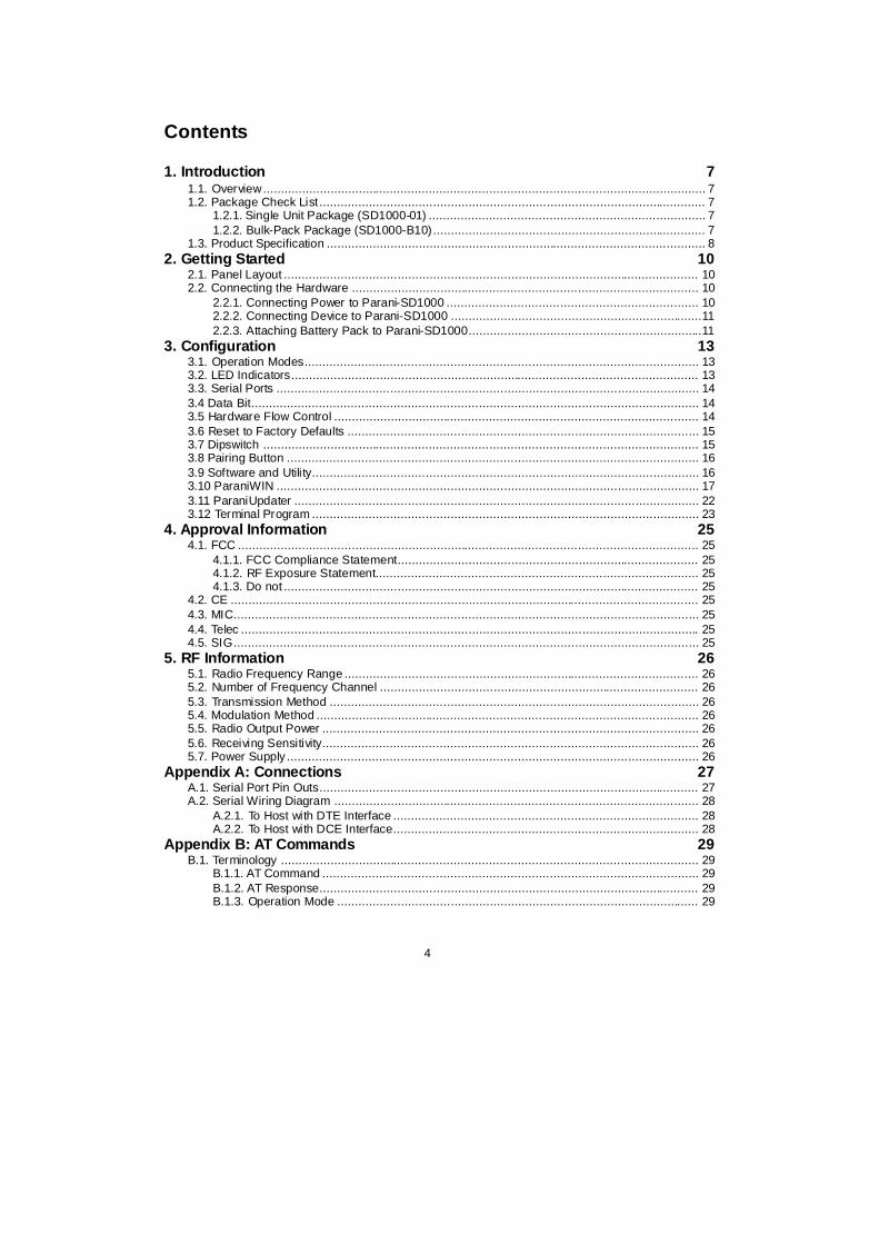
optional battery pack. To power the SD1000 from the external DC power adaptor or external powersource, connect the power jack to the power connector of the Parani-SD1000 using the DC poweradapter, USB power cable or DC power cable that is included in the package. If power is properlysupplied, the [Mode] lamp will display a green color.
Figure 2-2 Connecting Power to Parani-SD1000
2.2.2. Connecting Device to Parani-SD1000
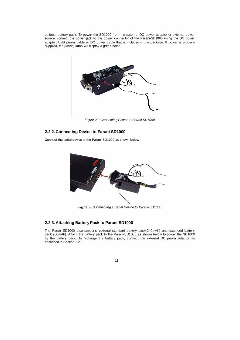
Connect the serial device to the Parani-SD1000 as shown below.
Figure 2-3 Connecting a Serial Device to Parani-SD1000
2.2.3. Attaching Battery Pack to Parani-SD1000
The Parani-SD1000 also supports optional standard battery pack( 240mAh) and extended batterypack(900mAh). Attach the battery pack to the Parani-SD1000 as shown below to power the SD1000by the battery pack. To recharge the battery pack, connect the external DC power adaptor asdescribed in Section 2.2.1.

12
Figure 2-4 Attaching Batter Pack to Parani-SD1000

13
3. Configuration
3.1. Operation Modes
In addition to the serial port configurations the Parani-SD1000 also requires some settings forBluetooth. For getting the most out of Parani-SD1000, user should understand the following Bluetoothconnection schemes.
A Bluetooth device can play a role as a master or slave. Master tries to connect itself to otherBluetooth devices, and slave is waiting to be connected from other Bluetooth devices. A Bluetoothconnection is always made by a pair of master and slave devices. A slave can be in two modes,Inquiry Scan or Page Scan mode. Inquiry Scan mode is waiting for a packet of inquiry from otherBluetooth device and Page Scan mode is waiting for a packet of connection from other Bluetoothdevice. Every Bluetooth device has its unique address, called BD (Bluetooth Device) address, which iscomposed of 12 hexa-decimal numbers.
Parani-SD1000 has 4 operation modes as follows. Each mode can be identified with LED indicators asillustrated in next section.
Table 3-1 The Parani-SD1000 Operation ModesMode Description
Mode0 In this mode, there is no response when power on or software reset, and Parani-SD1000 isjust waiting for AT command input. Neither master nor slave is assigned to Parani-SD1000 inmode0. User can change the configuration parameters of Parani-SD1000 in this mode.
Parani-SD1000 must be in Mode0, when it is directly controlled by AT commands.
The factory default is set to Mode0.
Mode1 Parani-SD1000 tries to connect the last connected Bluetooth device.Parani-SD1000 in Mode1 is to be a master and tries to connect the last connected Bluetoothdevice.Parani-SD1000 always stores the BD address of the Bluet ooth device to which Parani-SD1000 has connected last. When Parani-SD1000 is initially used or after hardware reset,there is no BD address stored in Parani-SD1000. In this case, Mode1 will not be able to workproperly. The mode change to Mode1 can be made after Parani-SD1000 succeeds to connectto one other Bluetooth device. Once changed to Mode1, Parani-SD1000 will try to connectautomatically the last connected Bluetooth device whenever the unit is powered on or softwarereset.Parani-SD1000 in Mode1 cannot be discovered or connected by other Bluetooth devices.
Mode2 Parani-SD1000 is waits for a connection from the last connected Bluetooth device.Parani-SD1000 in Mode2 is to be a slave and waiting for the connection only from the lastconnected Bluetooth device. Just like Mode1, if there is no BD address stored in Parani-SD1000, the mode change from other operation modes to Mode2 is not work properly. Oncechanged to Mode2, Parani-SD1000 will wait for the connection from the last connectedBluetooth device whenever the unit is powered on or software reset.Parani-SD1000 in Mode2 cannot be discovered or connected to Bluetooth devices other thanthe last connected device.
Mode3 Parani-SD1000 is waiting for the connection from any other Bluetooth devices. In Mode 3 theParani-SD1000 is discoverable and can be connected to by other Bluetooth devices.
3.2. LED Indicators
RS232- Tx and RS232- Rx LED will flash accordingly when data is transmitted. For small datatransmissions, it may be hard to recognize the quick flashing action of the LED. Charge Led and Lowbattery LED will be off, if you don’t use battery pack.

14
Table 3-2 The Parani-SD1000 LED Indicators
Indicator Mode LED Connect LED Charge LED Low batteryLED
Mode 0 Green┏━━━━━
Mode 1 Green(every 1 sec) ┏┓
Mode 2 Green(every 3 sec) ┏┰┓
Mode 3 Green(every 3 sec) ┏┰┰┓
Connected Green(every 1 sec) ┏┓
Charging Red┏━━━━━
ChargingComplete
Green┏━━━━━
Low battery Red┏━━━━━
3.3. Serial Ports
The applicable settings for serial ports are as follows.
Table 3-3 The Parani-SD1000 Serial Port SettingsSerial Port Settings Values
Baud rate 1200, 2400, 4800, 9600, 19200, 384 00, 57600, 115200, 230400, 460800, 921600
Data bite 8
Parity No parity, Even parity, Odd parity
Stop bit 1 , 2
Hardware Flow Control Use, No Use
The values in box are the factory defaults. The flow control setting is configurable only through dipswitch.
3.4 Data Bit
Parani-SD1000 supports only 8 data bit. In the case of 7 data bit and even/odd parity, use SD 8 databit and none parity. At this time, master and slave are Parani-SD, Parani-ESD or Parani-MSP series.But 7 data bit and none parity is not support.
3.5 Hardware Flow Control
Parani-SD1000 plugged into its host system transmits data from host to the other side Bluetooth

15
device. This data is saved temporarily in the internal buffer of Parani-SD1000 and sent repeatedly untilthe transmission is completed packet by packet. When the radio transmission condition is not goodenough to send data promptly, it can cause a transmission delay. If the host sends more data when thebuffer is full, buffer overflow will make Parani-SD1000 malfunction consequently. In order to preventthis buffer overflow, Parani-SD1000 works as follows.
When using hardware flow control, Parani-SD1000 disables RTS so that it stops receiving any furtherdata from the host when the buffer becomes full. RTS will be re-enabled again to begin receiving datafrom the host when the buffer has created more room for more data.
When hardware flow control is not being used, the Parani-SD1000 clears the buffer to secure room forthe next data when the buffer becomes full. This can mean a loss of data may occur. As thetransmission data becomes large, the possibility of data loss becomes greater.
For large data transmissions, the use of hardware flow control is highly recommended.
3.6 Reset to Factory Defaults
To set all the configuration settings to its factory default parameters, press the reset button, depicted inFig. 3-1. Press and hold (for at least 1 sec) the reset button with a narrow pointed tool like paper clip.Reset works only when power is on.
3.7 Dipswitch
With the combination of 4 slot dipswitches, baud rate and hardware flow control can be set.
Figure 3-1 The Parani-SD1000 Dipswitch
Upper 3 dipswitches are used for setting the baud rate, and bottom dipswitch is used for settinghardware flow control option. If the baud rate needs to a baud rate not shown below, ParaniWIN orterminal program should be used to set these speeds. To set a baud rate not shown below thedipswitches should be in the S/W Config setting. When in the S/W Config setting the baud rate will goback to 9600 as default.
Table 3-4 Baud rate Settings by Dipswitches2400 4800 9600 19.2K 38.4K 57.6K 115.2K S/W
ConfigBaud rate
Table 3-5 Hardware Flow Control Settings by DipswitchesNo Use UseHardware Flow Control
Handshaking
Pairing Button
Dip switchReset

16
* Note: You cannot set the Parani-SD1000 to a Baud rate of 1200 and 230K by way of the Dipswitch. Ifyou want to use them, to set these speeds, please configure the dipswitch to S/W Config setting anduse ParaniWIN or AT commands. Please refer to ParaniWIN and Appendix B.3.4AT+UARTCONFIG,Baudrate,Paraty,Stopbit.
3.8 Pairing Button
Parani-SD1000 provides Pairing Button for instant configuration without a PC to make an automaticconnection between two Parani-SD1000s. In this example we will refer to the two Parani-SD1000s asSD1 and SD2, respectively. In pairing status, SD changes IAC value automatically (reference C.19).
Step 1. Turn on SD1 and SD2 and Factory reset both of them by pressing Factory Reset Button.Step 2. Press the Pairing Button of SD1 for 2 seconds until Mode LED blinks 3 times every 3 seconds.
Keep the power ON.Step 3. Press the Pairing Button of SD2 for 2 seconds until Mode LED blinks 3 times every 3 seconds.
Now press again the Pairing Button for 2 seconds until Mode LED blinks every second.Step 4. Wait for SD1 & SD2 to connect to each other until the Connect LED’s of SD1 and SD2 blink
every 1 second. It takes about 10 seconds to make a connection. If there are many Bluetoothdevices nearby, it may take longer.
Step 5. Turn SD1 off and on. Mode LED blinks 3 times in green every 3 seconds.Step 6. Turn SD2 off and on. Mode LED blinks in green every second.Step 7. Now SD1 and SD2 are configured to make automatic connection to each other, whenever they
are powered on.
Using a pair of Parani-SD1000 in this fashion is similar to that of using a wireless serial cable.
* Note: When using the pairing buttons, the Command Response option will be deactivatedautomatically. The Parani-SD1000 will not send the response messages such as OK, Connect andDisconnect.
Table 3-6 Pairing Process by Pairing ButtonSD1 Status LED SD2 Status LED
1. Factory reset Mode0 Mode LED turns on 1. Factory reset Mode0 Mode LED turns on
2. Push pairingbutton
Mode3 Mode LED blinks 3times every 3 seconds
2. Push pairingbutton
Mode3 Mode LED blinks 3times every 3 seconds
3. Push pairingbutton again
Mode1 Mode LED blinksevery second
4. Connected Slave Connect LED blinksevery second
4. Connected Master Connect LED blinksevery second
3.9 Software and Utility
This configuration software and utility for firmware update is included with the product, which also canbe downloaded from http://www.sena.com
Table 3-7 Configuration SoftwareSoftware Purpose Operating System
ParaniWIN Configuration MS Windows 98SE or Higher
ParaniUpdater Firmware Update MS Windows 98SE or Higher

17
3.10 ParaniWIN
ParaniWIN is a program that runs on Microsoft Windows for the configuration of Parani-SD1000.Install ParaniWIN on your computer. Plug a Parani-SD1000 into the serial port of the computer andturn on the power. Run ParaniWIN.
Figure 3-2 Serial Port Setting
Set each option properly and click [Confirm]. If the settings of the Parani-SD1000 are different from theParaniWin, an error message will pop up. If the Parani-SD1000 is in the status of connection, warningmessage will pop up. Then the current connection can be cancelled by [Disconnect] button on themain window.

18
Figure 3-3 Main Window
Figure 3-4 Information Window
Serial port settings can be changed by <Start Configuration> and <ParaniWIN Configuration> ofParaniWIN in the menu bar at upper left corner of the window without re-running the ParaniWINprogram.
Figure 3-5 Menu Bar at Upper Left corner of ParaniWIN
When the ParaniWin software is able to access the Parani-SD1000 properly, the icons in the left sidewindow come will become available for use.
In device configuration window, hardware reset can be executed or operation mode and RS232 canbe configured as well. Security option also can be configured in this window.

19
Figure 3-6 Device Setting Window
Parani-SD1000 supports two security options, Authentication and Encryption. If you enable theAuthentication option, you must also enter a Pin Code value. If the authentication is enabled, theconnection, between the Master and Slave device must share the same Pin Code. In case that Parani-SD1000 connects to another Bluetooth device, that requires authentication, you must know the otherdevice’s Pin Code. In general, most Bluetooth devices have a pincode of 1234 or 0000. If you checkEncryption option, the Parani-SD1000 will encrypt packets and sent to the device. The Encryptionoptions works well in case that only one of the devices between Master and Slave use the Encryptionoption.
Parani-SD1000 has 4 response messages, ‘OK’, ‘ERROR’, ‘CONNECT’, and ‘DISCONNECT’. Insome cases, these responses can affect the host system unexpectedly. To prevent this, user can setthe Command response to ON or OFF.
For Parani-SD1000, hardware flow control can be configured only by dip switch. And parity, stop bitcan be configured only SW config mode. Thus H/W Flow Control option will not work in this case.When the dipswitch value isn’t ATcommand mode, the Baud Rate menu will be disabled.
Click [Apply] button to apply any changes made to the Parani-SD1000.
Connection(out) icon will show the following window to search and connect other Bluetooth devices.

20
Figure 3-7 Connection (out) Window
Click [Search] button to search nearby Bluetooth devices. Once several Bluetooth devices has beenfound, select one of the devices and click the [Connect] button. The selected Bluetooth device must bediscoverable and connectable. Click [Disconnect] button to cancel the connection.
After the connection has been established, you will be able to test signal strength by pushing theSTART button.

21
Figure 3-8 Signal Strength Test
The signal strength test shows LInkQuality and RSSI values. The closer LinkQuality is to 255 andRSSI is to 0, this means the Parani-SD1000 has a good connection to the connected Bluetooth device.In general, the wireless connectivity is at its best within 10 meters. You can push the STOP button atanytime in order to terminate the signal strength test. The signal strength test will continue until theSTOP button is pushed. If you close the ParaniWIN Window without pushing the STOP button, youmust restart Parani-SD1000 to terminate the test.
Connection(in) icon will show the following window, which enables the Parani-SD1000 to wait for aconnection from another Bluetooth device. If the waiting time is set to 0, Parani-SD1000 willcontinually wait for connection until [Cancel] button is clicked.
Figure 3-9 Connection (in) Window
If the Connection Wizard icon is clicked, an easy to use pairing menu will appear:

22
Figure 3-10 Connection Wizard Window
In this example we will refer to the two Parani-SD1000s as SD1 and SD2 respectively. To use thismenu, please do the following:
Step 1. Connect SD1 and then push the START button.Step 2. Disconnect SD1, connect SD2 and then push the Next but ton after setting up Slave
configuration. At this time, the dip switch value should be ATcmd mode. The flow control setting canbe changed only through dip switch.
Step 3. Disconnect SD2, once again connect SD1 and then push the Finish button. The pairingconfiguration should be completed. Make sure that each Parani-SD1000’s connect LED is on. At thispoint, when both Parani-SD1000’s restart the connection will be established automatically.
3.11 ParaniUpdater
Parani-SD1000 supports firmware updates. You can download new firmware images for the Parani-SD1000 at http://www.sena.com. With the ParaniUpdater, you can update the firmware of Parani-SD1000 by selecting the firmware image file and pushing Start button.
* Note: DO NOT power off Parani-SD1000 while the firmware update is progressing, this may damagethe Parani-SD1000.

23
Figure 3-11 ParaniUpdater Window
3.12 Terminal Program
A terminal program is typically an application that will enable a PC to communicate directly with amodem. If you are using Windows 98SE or higher version of Windows, HyperTerminal program isincluded as part of the operating system. Parani-SD1000 provides some extended AT commands forconfiguration of the Parani-SD1000.
This manual will explain the method using HyperTerminal. If you need to install HyperTerminal, clickstart>setting>control panel>add/remove programs. For more precise details on HyperTerminalinstallations, please refer to Microsoft Windows Help section..
Figure 3-12 HyperTerminal

24
Attach Parani-SD1000 to serial port of host computer and power on the Parani-SD1000. Check ModeLED. (See 3.2)
Make sure that the Connect LED is turned off and the Stanby LED is turned on before attempting tosend any kind of AT commands to the Parani-SD1000. Then launch HyperTerminal, it can usually befound in start >programs >accessories >communication >HyperTerminal. Select the Serial port thatParani-SD1000 is connected to.
Select the Serial port setting in the window displayed, please make sure the serial settings inHyperterminal are set to the same settings as the Parani-SD1000’s serial settings.
To view the AT commands that are being typed, you will need to enable the local echo option. Go toFile->Properties->Settings->ASCII setup and select the “Echo typed characters locally” option.
For expanded AT commands, please refer to Appendix A. AT commands.
Example of AT commands:at+btinfo?
00015B446655,SD1000v1.0.0-x446655,MODE0,STANDBY,0,0,NoFC
OKatd 000195000001OK
CONNECT 000195000001

25
4. Approval Information
4.1. FCC
4.1.1. FCC Compliance Statement
This device complies with part 15 of the FCC Rules. Operation is subject to the following twoconditions:
(1) This device may not cause harmful interference, and(2) This device must accept any interference received,
Including interference that may cause undesired operation
4.1.2. RF Exposure Statement
The equipment complies with FCC RF radiation exposure limits set forth for an uncontrolledenvironment. This device and its antenna must not be co-located or operation in conjunction with anyother antenna or transmitter.
4.1.3. Do not
Any changes or modifications to the equipment not expressly approved by the party responsible forcompliance could void user’s authority to operate the equipment.
4.2. CE
4.3. MIC
4.4. Telec
4.5. SIG

26
5. RF Information
5.1. Radio Frequency Range
2.402~2.480GHz
5.2. Number of Frequency Channel
79 channels
5.3. Transmission Method
FHSS (Frequency Hopping Spread Spectrum)
5.4. Modulation Method
GFSK (Gaussian-filtered Frequency Shift Keying)Pi/4 DQPSK (pi/4 rotated Differential Quaternary Phase Shift Keying)8DPSK (8 phase Differential Phase Shift Keying)
5.5. Radio Output Power
Products Radio Output Power
Parani-SD1000 +18dBm
5.6. Receiving Sensitivity
Products Radio Output Power
Parani-SD1000 -88dBm
5.7. Power Supply
Products Radio Output Power
Parani-SD1000 DC5.0 ~ 12V

27
Appendix A: Connections
A.1. Serial Port Pin Outs
Parani-SD is a DCE device compatible with the RS232 standard, a DB9 female interface.
Figure A-1 Pin layout of the DB-9 female connector
Table A-1. Pin assignment of the DB- 9 female connector
Pin # Signal Direction Description
1 DCD Output Bluetooth Connect Detect
2 TxD Output Transmitted Data
3 RxD Input Received Data
4 DSR Input Data set ready
5 GND - Signal Ground
6 DTR Output Data terminal ready
7 CTS Input Clear to Send
8 RTS Output Ready to send
9 Vcc Input (5V ~ 12V)

28
A.2. Serial Wiring Diagram
A.2.1. To Host with DTE Interface
A.2.2. To Host with DCE Interface

29
Appendix B: AT Commands
B.1. Terminology
B.1.1. AT Command
AT command set is the H Tin fact standardT H H TlanguageT H for controlling H TmodemsT H. The AT command set wasdeveloped by HTHayes TH and is recognized by virtually all H Tpersonal computerT H modems. Parani-SDprovides the extended AT command set to control and configure the serial parameters and Bluetoothconnection.
B.1.2. AT Response
Parani-SD replies to AT commands with 4 kinds of message, ‘OK’, ‘ERROR’, ‘CONNECT’ and‘DISCONNECT’.
B.1.3. Operation Mode
Mode Description
Mode0 Waiting for AT commands
Mode1 Attempting to connect the last connected Bluetooth device
Mode2 Waiting for the connection from the last connected Bluetooth device
Mode3 Waiting for the connection from any other Bluetooth device
B.1.4. Operation Status
Status Description
Standby Waiting for AT commands
Pending Executing tasks
Connect Transmitting data
B.1.5. Security
Security Description
Authentication Pin Code (or Pass key)
Encryption Data encryption

30
B.1.6. Symbols
The symbols are used for the description of command syntax as follows:
Symbols Meaning ASCII Code
Carriage return 0x0D
Line feed 0x0A
Carriage return + Line feed
112233445566 Bluetooth device address
N or m One digit decimal number
to Timeout in seconds
B.2. Command Category
Command Category Index AT Commands
RESET 12
ATZAT&F
SERIAL PORT 34
ATAT+UARTCONFIG,b,p,s
Information 56789
AT+USEDIP?AT+BTINFO?AT+BTINQ?AT+BTLAST?AT+BTVER?
Mode 10 AT+BTMODE,n
Status 11121314151617
+++AT+SETESC,nnATOAT+BTCANCELAT+BTSCANAT+BTSCAN,n,toAT+BTSCAN112233445566,to
Connection 181920
ATDATD112233445566ATH
Security 2122232425
AT+BTKEY=$stringAT+BTSD?AT+BTCSDAT+BTFP,nAT+BTSEC,a,e
BLUETOOTH
Miscellaneous 262728
AT+BTNAME=$stringAT+BTLPM,nAT+BTRSSI,n
S-REGISTER 293031
AT&VATSnn?ATSnn=mm
31
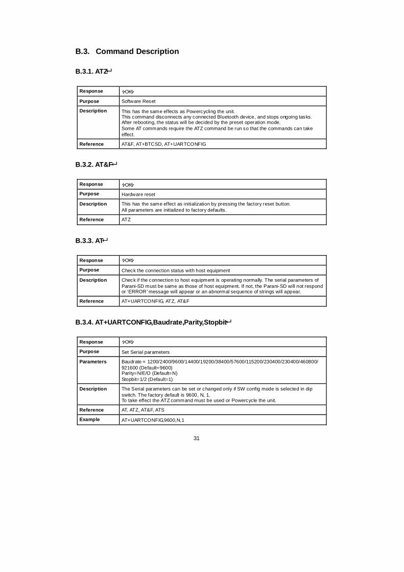
B.3. Command Description
B.3.1. ATZ
Response OK
Purpose Software Reset
Description This has the same effects as Powercycling the unit.This command disconnects any connected Bluetooth device, and stops ongoing tasks.After rebooting, the status will be decided by the preset operation mode.Some AT commands require the ATZ command be run so that the commands can takeeffect.
Reference AT&F, AT+BTCSD, AT+UARTCONFIG
B.3.2. AT&F
Response OK
Purpose Hardware reset
Description This has the same effect as initialization by pressing the factory reset button.All parameters are initialized to factory defaults.
Reference ATZ
B.3.3. AT
Response OK
Purpose Check the connection status with host equipment
Description Check if the connection to host equipment is operating normally. The serial parameters ofParani-SD must be same as those of host equipment. If not, the Parani-SD will not respondor ‘ERROR’message will appear or an abnormal sequence of strings will appear.
Reference AT+UARTCONFIG, ATZ, AT&F
B.3.4. AT+UARTCONFIG,Baudrate,Parity,Stopbit
Response OK
Purpose Set Serial parameters
Parameters Baudrate = 1200/2400/9600/14400/19200/38400/57600/115200/230400/230400/460800/921600 (Default=9600)Parity=N/E/O (Default=N)Stopbit=1/2 (Default=1)
Description The Serial parameters can be set or changed only if SW config mode is selected in dipswitch. The factory default is 9600, N, 1.To take effect the ATZ command must be used or Powercycle the unit.
Reference AT, ATZ, AT&F, ATS
Example AT+UARTCONFIG,9600,N,1

32
B.3.5. AT+USEDIP?
Response m
Purpose Check the Baud rate set by the dip switch
Description m=0: Dip switches are set to ‘S/W Config’m=1: Please view the dipswitches to view your baud rate.
Reference AT, ATZ, AT&F, ATS
B.3.6. AT+BTINFO?
Response 112233445566,DeviceName,Mode,Status,Auth,Encryp,FlowControlOK
Purpose Display Bluetooth settings
Description The current Bluetooth settings are displayed including BD address, Device name,Operation mode, Operation status, Authentication, Data Encryption, and Hardware FlowControl. The initial value of Device name is ‘PSD100v1.1.3-445566’. PSD stands forParani-SD, v1. 1.3 for the version of firmware, and 445566 for the last 6 digits of BDaddress.Mode=MODE0/MODE1/MODE2/MODE3Status=STANDBY/PENDING/CONNECTAuth=0/1 (Authentication is not activated when 0)Encrypt=0/1 (Encryption is not activated when 0)FlowControl=HWFC/NoFC
Reference AT+BTNAME, AT+BTMODE, AT+BTSEC, ATS14?
B.3.7. AT+BTINQ?
Response 112233445566,FriendlyName,CoD112233445566,FriendlyName,CoD112233445566,FriendlyName,CoDOK
Purpose Search Bluetooth devices nearby
Description The Bluetooth devices in Inquiry scan mode nearby are displayed with their BD addresses,Device names, and Class of device.Maximum 15 devices are scanned for 30 seconds. (Default 10 value in S-register 6)
Reference AT+BTSCAN, ATD, AT+BTINFO?
B.3.8. AT+BTLAST?
Response 112233445566
Purpose Display the BD address of the last connected device
Description The Bluetooth device last connected to this Parani-SD is displayed with its BD address.
Reference AT+BTSCAN, ATD, AT+BTINFO?, AT+BTINQ?

33
B.3.9. AT+BTVER?
Response SD1000v1.0.0OK
Purpose Display device firmware version
Description Display device firmware version
Reference AT+BTINFO?
B.3.10. AT+BTMODE,n
Response OK
Purpose Set operation mode
Parameters n=0: MODE0 (Default)n=1: MODE1n=2: MODE2n=3: MODE3
Description When the operation status is ‘Pending’currently, change the status to ‘Standby’withAT+BTCANCEL prior to this command.To take effect the ATZ must be executed or Powercycle the unit
Reference AT+BTINFO?
Example AT+BTMODE,2OKATZ
B.3.11. +++
Response OK
Purpose Convert the operation status of ‘Connect’to ‘Standby’
Description In ‘Connect’status, data from host is transmitted to the other side Bluetooth device, andany AT command is not accepted but this command, which is not echoed on the screen.When Parani-SD encounters a character ‘+’from host, it stops the data transmission andwaits for next 2 characters. If the next 2 characters aren’t both ‘+’, it restart to transmit dataincluding the first ‘+’as well. If not, it converts the operation status to ‘Standby’.If the data from host includes ‘+++’, it will convert the operation status to ‘Standby’. Noticethat Parani-SD holds data transmission when it encounters ‘+’, until receiving nextcharacter.‘+’is an escape sequence character by default, which is changeable by AT+SETESC.
Reference AT+SETESC, ATO, AT+BTCANCEL
B.3.12. AT+SETESC,nn
Response OK
Purpose Change the escape sequence character
Description Escape sequence character set to ‘+’by default is changeable.The parameter nn must be a printable character.

34
Reference +++, ATO
Example AT+SETESC,42
B.3.13. ATO
Response None
Purpose Convert the operation status of ‘Standby’to ‘Connect’
Description You can convert the operation status of ‘Standby’to ‘Connect’ready to transmit data.
Reference +++, AT+SETESC
B.3.14. AT+BTCANCEL
Response OK
Purpose Terminate the current task
Description This terminates a current executing task, such as Inquiry scan and Page scan, thenconverts the operation status to ‘Standby’
Reference AT+BTSCAN, ATD, AT+BTINQ?
B.3.15. AT+BTSCAN
Response OKCONNECT 112233445566
Purpose Wait for inquiry and connection from other Bluetooth devices
Description This allows the inquiry and connection from the other Bluetooth devices. The operationstatus will be in ‘Pending’after this command. When connection is made and released, theoperation status is back to ‘Pending’. To convert the operation status to ‘Standby’AT+BTCANCEL must be used.This has the same effect as AT+BTSCAN, 3, 0.When connection is made with other Bluetooth device, response will be ‘CONNECT’withits BD address.
Reference ATD, AT+BTINQ?, AT+BTCANCEL
B.3.16. AT+BTSCAN,n,to
Response OKCONNECT 112233445566orOKERROR
Purpose Wait for inquiry and connection from other Bluetooth devices for a given duration
Parameters n=1: Allows Inquiry scann=2: Allows Page scann=3: Allows both of Inquiry scan and Page scanto= Time duration in seconds

35
Description For the given to, Parani-SD is waiting for the inquiry and connection from other Bluetoothdevices. If the parameter of to is 0, it will wait forever.When connection is made with other Bluetooth device, response will be ‘CONNECT’withits BD address. If there is no connection made within this time duration, response is‘ERROR’and the operation status becomes to ‘Standby’.
Reference ATD, AT+BTINQ?, AT+BTCANCEL
Example AT+BTSCAN,2,30
B.3.17. AT+BTSCAN112233445566,to
Response OKCONNECT 112233445566orOKERROR
Purpose Wait for connection by a Bluetooth device with a given BD address
Parameters 112233445566=BD addressto= time duration in seconds
Description Parani-SD will wait to be connected to by the Bluetooth device with the given BD address.If the parameter of to is 0, it will wait forever.When connection is made with the Bluetooth device, response will be ‘CONNECT’with itsBD address. If there is no connection made within this time duration, response is ‘ERROR’and the operation status becomes ‘Standby’.
Reference ATD, AT+BTINQ?, AT+BTCANCEL
Example AT+BTSCAN000B530011FF,30
B.3.18. ATD
Response OKCONNECT 112233445566orOKERROR
Purpose Connect to the last connected Bluetooth device
Description Parani-SD saves the BD address of the Bluetooth device most recently connected to.If it fails to make a connection, response will display an ‘ERROR’.
Reference AT+BTINQ?, AT+BTSCAN
B.3.19. ATD112233445566
Response OKCONNECT 112233445566orOKERROR
Purpose Connect to a specific Bluetooth device with a given BD address
Parameters 112233445566 = BD address

36
Description Parani-SD attempts to connect to the Bluetooth device with the given BD address. To makesuccessful connection, the Bluetooth device must be in Page scan mode. This attemptcontinues for 5 minutes.If it fails to make connection, response is ‘ERROR ’.
Reference AT+BTINQ?, AT+BTSCAN
Example ATD000B530011FF
B.3.20. ATH
Response OKDISCONNECT
Purpose Release the current connection
Description The current Bluetooth connection will be disconnected. It takes about 30 seconds to detectan abnormal disconnection such as power off and moving out of service range.
Reference ATD, AT+BTSCAN
B.3.21. AT+BTKEY=$string
Response OK
Purpose Change pin code
Parameters $string= New pin code (Default=”1234”)
Description Pin code is a string, which allows up to 16 alpha-numeric characters. Based on this pincode, Parani-SD generates a link key which is used in actual authentication process
Reference AT+BTCSD, AT+BTFP, AT+BTSD?, AT+BTSEC, ATZ, AT&F
Example AT+BTKEY=”apple”
B.3.22. AT+BTSD?
Response 112233445566OK
Purpose Display a list of Bluetooth devices sharing the same pin code
Description Once a connection is made with a pin code, Parani-SD saves the Bluetooth device with itslink key, generated by the pin code. The connection to a device listed in Parani-SD can bemade automatically without the authentication process. The maximum number kept on thelist is 5.
Reference AT+BTCSD, AT+BTFP, AT+BTKEY, AT+BTSEC, ATZ, AT&F
B.3.23. AT+BTCSD
Response OK
Purpose Clear the list of Bluetooth devices sharing the same pin code
Description This clears the list of Bluetooth devices linked with the same key in flash memory. To take

37
effect the ATZ command must be used or Powercycle the unit.
Reference AT+BTFP, AT+BTKEY, AT+BTSD?, AT+BTSEC, ATZ, AT&F
B.3.24. AT+BTFP,n
Response OK
Purpose Set generation of link key every time of connection
Parameters n=0: Inactivate (Default)n=1: Activate
Description If n is set to 1, Parani-SD asks for the pin code every time a connection is made. This canbe used to increase security.
Reference AT+BTCSD, AT+BTKEY, AT+BTSD?, AT+BTSEC, ATD, ATZ, AT&F
B.3.25. AT+BTSEC,Authentication,Encryption
Response OK
Purpose Set authentication and data encryption
Parameters Authentication=0: Inactivate (Default)Authentication=1: ActivateEncryption=0: Inactivate (Default)Encryption=1: Activate
Description If the authentication is activated, the pin code must be set by AT+BTKEY command. Dataencryption cannot be used when authentication is not enabled, i.e. Authentication=0 andEncryption=1 will not work properly.
Reference AT+BTCSD, AT+BTFP, AT+BTSD?, AT+BTSD?, ATZ, AT&F
B.3.26. AT+BTNAME=$string
Response OK
Purpose Change device name
Parameters $string= New device name (Default=”PSDv1.1.3-445566”)
Description Parani-SD can have a user friendly name for easy identification. The name allows up to 30alpha-numeric characters.
Reference AT+BTINFO?, AT+BTINQ?
Example AT+BTNAME=”My-Parani-SD”
B.3.27. AT+BTLPM,n
Response OK
Purpose Set low power mode
Parameters n=0: Inactivate (Default)

38
n=1: Activate
Description During no data transmission, Parani-SD can be in low power mode to save the power. Ittakes a few seconds to wake the Parani-SD out of low power mode.
B.3.28. AT+BTRSSI,n
Response OK0,255,0,0 (repeatedly)
Purpose Testsignal strength
Parameters n=0: Stop signal strength testn=1: Start s ignal strength test
Description When Bluetooth connection is established, you can use this command in Standby status.The signal strength will be displayed repeatedly in order of Status, LinkQuality, Status,RSSI. If the LinkQuality is close to 255 and RSSI is close to 0, the signal strength is in goodstanding.
Example +++AT+BTRSSI,1OK0,255,0,0
B.3.29. AT&V
Response S0:m0;S1:m1; …Sn:mnOK
Purpose Display all the S-registers
Description All parameters are stored at S-register in flash memory. These values are sustained until ahardware reset.
Reference ATS
B.3.30. ATSnn?
Response valueOK
Purpose Display a given S-register
Parameters nn= Address of S-register
Description A specific S-register will be displayed.
Reference AT&V
B.3.31. ATSnn=mm
Response OK
Purpose Change S-register value
Parameters nn= Address of S-register

39
mm= New value of S-register
Description Some S-registers are optimized for the overall performance and protected and cannot bechanged. When users try to change these S-registers, response is ‘ERROR’.For details of S-register, refer Appendix. B.
Reference AT&V
Example ATS10=0
B.4. Command Validity
Operation StatusAT Command
Standby Pending Connect
AT ○ ○
ATZ ○ ○
AT&F ○ ○
AT+BINQ? ◎
ATD112233445566 ◎
ATD ◎
AT+BTSCAN ◎
AT+BTSCAN,n,to ◎
AT+BTSCAN112233445566,to ◎
AT+BTCANCEL ○
+++ ○
AT+SETESC ◎
ATO ●
ATH ●
AT+BTSEC,Auth,Encr ◎
AT+BTLAST? ○ ○
AT+BTMODEn ◎
AT+BTNAME=”Name” ◎
AT+BTKEY=”nnnn ” ◎
AT+BTINFO? ○
AT+BTLPM,n ◎
AT+BTSD? ○ ○
AT+BTCSD ◎
AT+BTFP,n ◎
AT+UARTCONFIG,b,p,s ◎

40
AT+USEDIP? ○ ○
AT+BTVER? ○ ○
AT+BTRSSI,n ●
◎ Valid only when Parani-SD is not connected to other Bluetooth device.
● Valid only when Parani-SD is connected to other Bluetooth device.

41
Appendix C: S-Register
S-registers contains 52 parameters for the Parani-SD Series. These are stored in flash memory andthe values will be saved unless hardware reset is executed. The value of S-register can be accessedand changed with ATS command. Some S-registers not shown below are set to maximize theperformance of Parani-SD Series. Thus it is not recommended to change these S-registers.Changing the values of S-register can only be done in the Standby mode. Turn Parani-SD off and on.
C.1. S1: Force to Reconnect (default 1)
S1=0, Parani-SD in Mode1 does not try to reconnect when disconnected.S1=1, Parani-SD in Mode1 keeps trying to reconnect when disconnected.
C.2. S3: Stream UART Policy (default 0)
S3=0, the priority of UART streaming is throughput.S3=1, the priority is latency, which minimizes the delay of data transmission. This is useful in case of
transmiting very small data quickly.When this value is 1, in order to minimize latency, Parani-SD sends the received data immediately.When this value is 0, the Parani-SD maximizes throughput, the Parani-SD stores received data for ashort time and sends a large data packet. If the packet length is less than 100 bytes, having latencybeing the priority is recommended. If the packet length is more than 100 bytes, having throughput asthe priority is recommended. Also, if you want to use high baudrate, throughput priority will be moreeffective. Just for reference, the buffer length for receiving data is 2 Kbytes.
C.3. S4: Enable Remote Name Query (default 1)
S4=0, Parani-SD will query only the BD address. This speeds up the inquiry process.S4=1, Parani-SD will query the BD address, device name and class of device.When this value is 1, Parani-SD finds not only BD address but also friendly name. When this value is0, Parani-SD finds only BD address. When set to 0 this will make queries much faster. When using thepairing button, finding friendly name will be omitted automatically.
C.4. S6: Enable Low Power Mode (default 0)S6=0, deactivate Low Power Mode.S6=1, activate Low Power Mode.This value decides whether Parani-SD works in Low Power Mode or not. When this value is 0, Parani-SD works only in active power mode. When Parani-SD works in Low Power mode, delay intransferring data may occur.
C.5. S10: Enable Response Message (default 1)
S10=0, Parani-SD does not send response messages to the host system.S10=1, Parani-SD sends response messages to host system.This value decides whether Parani-SD sends response messages such as OK, ERROR, CONNECT,DISCONNECT or not. When this value is 0, Parani-SD will not send any response messages. If theresponse messages conflicts with your host programs or devices that is connected to Parani-SD,change this value to 0.
C.6. S11: Enable Escape (default 1)
S11=0, Parani-SD does not allow escape sequence characters. The operation status of Connectcannot be changed to Standby. Since the Parani-SD skips the process of detecting escapesequence characters, more efficient data transmission can be had.
S11=1, Parani-SD allows for the escape sequence charactesr. Whenever it is needed, the Connectstatus can be changed to Standby.

42
C.7. S12: Clear Data Buffer When Disconnected (default 0)
S12=0, Parani-SD does not clear the data buffer when disconnected.S12=1, Parani-SD clears the data buffer when disconnected.
C.8. S13: Enable DCD Signal (default 1)
S13=0, DCD signal offS13=1, DCD signal on
C.9. S14: Enable DTR Transfer (default 1)
S14=0, DTR/DSR signal is transferred in a loop-back fashion.S14=1, DTR signal is transferred to DSR of remote device.
C.10. S15: Enable Disconnect by DTR (default 0)
S15=0, DTR signal cannot release the connection.S15=1, The Bluetooth connection can be released when DTR signal is off.This value decides whether Bluetooth connection is released when DTR signal drops or not. If thisvalue is 1, you can use DTR signal in order to disconnect Bluetooth connection.
C.11. S22: Faster Connection (default 0)
S22=0, noneS22=1, page scanS22=2, inquiry scanS22=3, page/inquiry scan
C.12. S23: Intercharacter Timeout Setting (default 0)
S23=0 : Not usedS23=1 : 1 x S26S23=2 : 10 x S26S23=3 : 100 x S26Connecting time is average 1.5sec faster than normal mode.
C.13. S24: Maximum Number of Inquiry Result (default 10)
The maximum number of inquiry list can be controlled. This value is up to 15.
C.14. S26: Intercharacter Timeout (default 0)
S23=1 x S26=50 : Timeout-> 50msecS23=2 x S26=50 : Timeout-> 500msecS23=3 x S26=3 : Timeout-> 300msec
* When 10 bytes data are sent every intercharacter timeout, they are sent separately by 10 bytes atthe optimal value. If the intercharater timeout is set below the optimal value, the date will be puttogether and sent by 20, 30, 40 bytes or more.
Intercharacter Timeout * Optimal Value(S23 x S26)50ms 180100ms 235
200ms 340

43
C.15. S28: Escape Sequence Character (default 43)
The decimal number of the ASCII code of escape sequence character can be controlled. The initialvalue is 43, the ASCII code of ‘+’.
C.16. S31: Page Timeout (default 300)
This is the timeout in seconds to attempt connection with the ATD command. After this timeout expires,the Parani-SD will restart automatically. If this value is 0, Parani-SD will attempt to connect withoutrestarting
C.17. S33: Inquiry Timeout (default 30)
This is the timeout in seconds to execute inquiry scan.
C.18. S37: Supervision Timeout (default 16000)
This is the timeout in 625μsec to presume disconnection, which is set to 16000 initially.16000625μsec=10sec)The smaller the value becomes, the more quickly Parani-SD can detect an abnormal disconnection.But when the communication is suspended, it may be regarded as disconnection.
C.19. S45: Inquiry Access Code (default 0x9E8B33)
Inquiry access code is used during inquiry state. The reserved IAC addresses are 0x9E8B00 ~0x9E8B3F. The general inquiry IAC is 0x9E8B33.Parani-SD is able to find the Bluetooth devices that are configured as the same IAC
C.20. S46: BD Address of Last Connected Device
This saves the BD address of the Bluetooth device connected most recently.
C.21. S48: Low Power Max Interval (default 5000)
This is the max interval value to use low power mode, which is set to 5000 initially. (5000 x 625μsec =3125msec)
C.22. S49: Low Power Min Interval (default 4500)
This is the min interval value to use low power mode, which is set to 4500 initially. (4500 x 625μsec =2812msec)A small interval increases power consumption, a large interval increases latency.
C.23. S52: Low Power Timeout (default 5)
This is the low power timeout value, which is set to 5 initially. (5sec)During no data transmission in the timeout, Parani-SD will be in low power mode to save the power.Therefore, it takes a few seconds to wake the Parani-SD out of low power mode.

44
Appendix D: Trouble Shooting
D.1. No Data Transmission
D.1.1. COM Port Settings
Check whether the Baud rate of Parani-SD matches that of its host equipment.Check whether the host equipment has a Data bit setting of 8. Parani-SD supports only 8 Data bitsettings. If your host equipment uses 7 Data bit and even or odd parity, it may work with a 8 Data bitand No parity setting. This is valid only when both DCE devices are the Parani-SD. In this case, setboth Parani-SDs to 8 Data bit and No parity. If one of DCE devices is another Bluetooth device suchas Bluetooth USB dongle,7 bit data configurations will not work.Check whether the Parity and Stop bit of Parani-SD match those of your host equipment. Parani-SDsupports No parity, Even parity and Odd parity, 1 and 2 Stop bit configurations.Check whether the host equipment of Parani-SD uses Hardware Flow Control. Parani -SD is initiallyset to Use of Hardware Flow Control. If your host equipment does not use Hardware Flow Control,please disable the Hardware flow control option by way of the dipswitch.Parani-SD does not support RS-232 break signal.
D.1.2. Pin Assignment
Parani-SD is a DCE device. If your host equipment is DTE, plug Parani-SD directly to the hostequipment or use straight RS- 232 cable. If your host equipment is DCE, use will need to use a crossover RS-232 cable (Null modem cable) or a Male to Male DB9 Null Modem adapter.
D.2. Data Loss or Malfunctioning
D.2.1. Hardware Flow Control
When transmitting large amounts of data with No Hardware Flow Control, Parani-SD may clear thedata buffer unexpectedly. The possibility becomes greater as the RF transmission environmentbecomes worse.
D.2.2. Response Message
AT response messages from the Parani-SD may affect the host system unexpectedly. Do not useParani-SD If your applications cannot allow for this wireless time delay.
D.3. Transmission Delay
D.3.1. RF Processing Delay
It takes 30msec approximately for a Parani-SD to complete a data transmission to the other Bluetoothdevice. This time delay cannot be reduced and may enlarge as the RF transmission environmentbecomes worse. Do not use Parani-SD If your applications cannot allow for this time delay.
D.3.2. RF Transmission Environment
If there are many Bluetooth devices working in a small area and/or the RF communication distance istoo great and/or there are some obstacles affecting RF performance, the Parani-SD repeats thetransmission packet by packet due to interferences and/or low RF performance. This may lead toincreased data transmission time delays.

45
Appendix E: Parani-SD1000 mechanical drawing
E.1. Parani-SD1000 mechanical drawing (mm)
101 with stub antenna
16
76 without antenna
15
31
14

46
E.2. Battery pack mechanical drawing (mm)
Standard Battery Pack
Extended Battery Pack

47
Appendix F: Warranty
F.1. GENERAL WARRANTY POLICY
Sena Technologies, Inc. (hereinafter referred to as SENA) warrants that the Product shall conform toand perform in accordance with published technical specifications and the accompanying writtenmaterials, and shall be free of defects in materials and workmanship, for the period of time hereinindicated, such warranty period commencing upon receipt of the Product.This warranty is limited to the repair and/or replacement, at SENA’s discretion, of defective or non-conforming Product, and SENA shall not be responsible for the failure of the Product to performspecified functions, or any other non- conformance caused by or attributable to: (a) any misapplicationor misuse of the Product; (b) failure of Customer to adhere to any of SENA’s specifications orinstructions; (c) neglect of, abuse of, or accident to, the Product; or (d) any associated orcomplementary equipment or software not furnished by SENA.Limited warranty service may be obtained by delivering the Product to SENA or to the internationaldistributor it was purchased through and providing proof of purchase or receipt date. Customer agreesto insure the Product or assume the risk of loss or damage in transit, to prepay shipping charges toSENA, and to use the original shipping container or equivalent.
F.2. LIMITATION OF LIABILITY
EXCEPT AS EXPRESSLY PROVIDED HEREIN, SENA MAKES NO WARRANTY OF ANY KIND,EXPRESSED OR IMPLIED, WITH RESPECT TO ANY EQUIPMENT, PARTS OR SERVICESPROVIDED PURSUANT TO THIS AGREEMENT, INCLUDING BUT NOT LIMITED TO THE IMPLIEDWARRANTIES OF MERCHANTABILITY AND FITNESS FOR A PARTICULAR PURPOSE. NEITHERSENA NOR ITS DEALER SHALL BE LIABLE FOR ANY OTHER DAMAGES, INCLUDING BUT NOTLIMITED TO DIRECT, INDIRECT, INCIDENTAL, SPECIAL OR CONSEQUENTIAL DAMAGES,WHETHER IN AN ACTION IN CONTRACT OR TORT (INCLUDING NEGLIGENCE AND STRICTLIABILITY), SUCH AS, BUT NOT LIMITED TO, LOSS OF ANTICIPATED PROFITS OR BENEFITSRESULTING FROM, OR ARISING OUT OF, OR IN CONNECTION WITH THE USE OF FURNISHINGOF EQUIPMENT, PARTS OR SERVICES HEREUNDER OR THE PERFORMANCE, USE ORINABILITY TO USE THE SAME, EVEN IF SENA OR ITS DEALER HAS BEEN ADVISED OF THEPOSSIBILITY OF SUCH DAMAGES. IN NO EVENT WILL SENA OR ITS DEALERS TOTAL LIABILITYEXCEED THE PRICE PAID FOR THE PRODUCT.
F.3. HARDWARE PRODUCT WARRANTY DETAILS
WARRANTY PERIOD: SENA warranties embedded hardware Product for a period of one (1) year,and external hardware Product for a period of three (3) or five (5) years according to the Product type.WARRANTY PROCEDURE: Upon return of the hardware Product SENA will, at its option, repair orreplace Product at no additional charge, freight prepaid, except as set forth below. Repair parts andreplacement Product will be furnished on an exchange basis and will be either reconditioned or new.All replaced Product and parts become the property of SENA. If SENA determines that the Product isnot under warranty, it will, at the Customers option, repair the Product using current SENA standardrates for parts and labor, and return the Product at no charge in or out of warranty.WARRANTY EXCLUSIONS: Damages caused by- Accidents, falls, objects striking the SENA product,- Operating the Product in environments that exceed SENA's temperature and humidity specifications,- Power fluctuations, high voltage discharges,- Improper grounding, incorrect cabling,- Misuse, negligence by the customer or any other third party,- Failure to install or operate the product (s) in accordance to their SENA User Manual,- Failure caused by improper or inadequate maintenance by the customer or any other third party,- Floods, lightning, earthquakes,

48
- Water spills,- Replacement of parts due to normal wear and tear,- Hardware has been altered in any way,- Product that has been exposed to repair attempts by a third party without SENA’s written consent,- Hardware hosting modified SENA Software, or non-SENA Software, unless modifications have beenapproved by
SENA.- Battery component capacity degradation due to usage, aging, and with some chemistry, lack ofmaintenance.
F.4. SOFTWARE PRODUCT WARRANTY DETAILS
WARRANTY PERIOD: SENA warranties software Product for a period of one (1) year.WARRANTY COVERAGE: SENA warranty will be limited to providing a software bug fix or a softwarepatch, at a reasonable time after the user notifies SENA of software non-conformance.
F.5. THIRD-PARTY SOFTWARE PRODUCT WARRANTY DETAILS
The warranty policy of the third-party software is conformed to the policy of the corresponding vendor


![Bluetooth Serial Adapter, SD1000 - Lemos InternationalDAT-G01R - DAT5-G01R 300 meters DAT5-G01R - DAT5-G01R 400 meters [Antennas] SAT-G01R: +1dBi Stub Antenna DAT-G01R: +3dBi Dipole](https://img.pdfslide.net/doc/110x75/6116036f2f7ac33c53401077/bluetooth-serial-adapter-sd1000-lemos-international-dat-g01r-dat5-g01r-300.jpg)


![[솔리드씽킹 9월호] 디자인, 3D프린팅, 제조업의 만남 ATCx에 … · 9월 18일 콘래드 호텔에서 개최되는 ATCx 알테어 테크놀로지 컨퍼런스에](https://img.pdfslide.net/doc/110x75/603de515d686ec37dc5b180c/eeoe-9-e-3deoe-oe-eoee-atcx-9.jpg)