Embed Size (px)
Citation preview
IEEE TRANSACTIONS ON INSTRUMENTATION AND MEASUREMENT, VOL. 52, NO. 5, OCTOBER 2003 1363
Parity Bit Signature in Response Data Compactionand Built-In Self-Testing of VLSI Circuits
With Nonexhaustive Test SetsSunil R. Das, Fellow, IEEE, Made Sudarma, Mansour H. Assaf, Member, IEEE, Emil M. Petriu, Fellow, IEEE,
Wen-Ben Jone, Senior Member, IEEE, Krishnendu Chakrabarty, Senior Member, IEEE, andMehmet Sahinoglu, Senior Member, IEEE
Abstract—The design of efficient time compression supporthardware for built-in self-testing (BIST) is of great importancein the design and manufacture of VLSI circuits. The test dataoutputs in BIST are ultimately compressed by the time compactionhardware, commonly called a response analyzer, into signatures.Several output response compaction techniques to aid in thesynthesis of such support circuits already exist in literature, andparity bit signature coupled with exhaustive testing is already wellknown to have certain very desirable properties in this context.This paper reports new time compaction techniques utilizing theconcept of parity bit signature that facilitates implementing suchsupport circuits using nonexhaustive or compact test sets, withthe primary objective of minimizing the storage requirements forthe circuit under test (CUT) while maintaining the fault coverageinformation as best as possible. Recently, Jone and Das proposed amultiple-output parity bit signature generation method extendingthe basic idea of Akers, for exhaustive testing of digital combina-tional circuits, where, given a multiple-output circuit, a parity bitsignature is generated by first XORing all the outputs to producea new output function and then feeding this resulting functionto a single-output parity bit signature generator. The method, asshown by the authors, preserves all the desirable properties ofthe conventional single-output response analyzers and can also beeasily implemented by using the current VLSI technology. Thesubject paper further augments the aforesaid concepts of Joneand Das, and proposes a multiple-output parity bit signature fornonexhaustive testing of VLSI circuits. Design algorithms areproposed in the paper, and the simplicity and ease of their imple-mentations are demonstrated with examples. Extensive simulationexperiments on ISCAS 85 combinational benchmark circuits usingFSIM, ATALANTA, and COMPACTEST programs demonstratethat the proposed signature generation method achieves high faultcoverage for single stuck-line faults, with low CPU simulationtime, and acceptable area overhead. A performance comparisonof the designed time compactors with conventional space-timecompaction is also presented to demonstrate improved tradeoff forthe new circuits in terms of fault coverage and the CUT resourcesconsumed contrasted with existing designs, and to appreciate theresulting performance enhancements.
Manuscript received December 15, 2002; revised June 29, 2003. This workwas supported in part by the Natural Sciences and Engineering ResearchCouncil of Canada under Grant A 4750.
S. R. Das, M. Sudarma, M. H. Assaf, and E. M. Petriu are with the School ofInformation Technology and Engineering, Faculty of Engineering, Universityof Ottawa, Ottawa, ON K1N 6N5, Canada.
W.-B. Jone is with the Department of Electrical and Computer Engineeringand Computer Science, University of Cincinnati, Cincinnati, OH 45221 USA.
K. Chakrabarty is with the Department of Electrical and Computer Engi-neering, Duke University, Durham, NC 27708 USA.
M. Sahinoglu is with the Department of Computer and Information Science,Troy State University Montgomery, Montgomery, AL 36103 USA.
Digital Object Identifier 10.1109/TIM.2003.818547
Index Terms—Built-in self-test (BIST), circuit under test (CUT),multiple-output parity bit signature generation, nonexhaustive orcompact test sets, parity testing, space-time compaction, stuck-linefaults, time compaction.
I. INTRODUCTION
A S the digital design moves through increased levels of in-tegration densities, it is desirable that better and effective
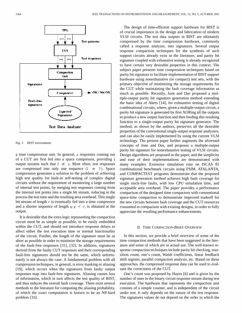
methods of testing be made available to ensure reliable systemsoperation. Frankly speaking, the concept of testing has broadapplicability, and as such, finding efficient testing techniquesthat guarantee correct systems performance has attracted con-siderable attention of the testing community for quite sometime[1]–[32]. The conventional testing techniques of digital systemsrequire application of test stimuli generated by a test patterngenerator (TPG) to the circuit under test (CUT) and subsequentcomparison of the produced responses with known correct re-sponses. However, for large circuits, because of higher storagerequirements for the fault-free responses, the procedure turnsout to be rather expensive, and hence alternative approaches aresought. Built-in self-testing (BIST) is a design approach that cansignificantly improve the testability of digital circuits and savetesting time. It combines concepts of both built-in test (BIT) andself-test (ST) in one termed built-in self-test (BIST). In BIST,test generation, test application, and response verification areall done through built-in hardware, which allows different partsof a chip to be tested in parallel, reducing the required testingtime, besides eliminating the necessity for external test equip-ments. A typical BIST environment, as shown in Fig. 1, usesa test pattern generator (TPG) that sends its outputs to a circuitunder test (CUT), and the resulting output streams from the CUTare fed into a response data analyzer. A fault is detected if theCUT response is shown to be different from that of the fault-freecircuit. The test data analyzer is comprised of a response com-paction unit (RCU), a storage for the fault-free responses of theCUT, and a comparator.
In order to reduce the amount of data represented by thefault-free and the faulty CUT responses, data compression isused to create signatures from the CUT and its correspondingfault-free circuit. BIST techniques use pseudorandom, pseu-doexhaustive, and exhaustive test patterns, or even sometimeson-chip storing of reduced test sets. The standard responsecompaction unit is comprised of a space compression unit and
0018-9456/03$17.00 © 2003 IEEE
1364 IEEE TRANSACTIONS ON INSTRUMENTATION AND MEASUREMENT, VOL. 52, NO. 5, OCTOBER 2003
Fig. 1. BIST environment.
a time compression unit. In general,responses coming outof a CUT are first fed into a space compressor, providingoutput streams such that . Most often, test responsesare compressed into only one sequence . Spacecompression generates a solution to the problem of achievinghigh test quality for built-in self-testing of complex digitalcircuits without the requirement of monitoring a large numberof internal test points, by merging test responses coming fromthe internal test points into a single bit stream, reducing in theprocess the test time and the resulting area overhead. This singlebit stream of length is eventually fed into a time compressorand a shorter sequence of length , is obtained at theoutput.
It is desirable that the extra logic representing the compactioncircuit must be as simple as possible, to be easily embeddedwithin the CUT, and should not introduce response delays toaffect either the test execution time or normal functionalityof the circuit. Further, the length of the signature must be asshort as possible in order to minimize the storage requirementsof the fault-free responses [31], [32]. In addition, signaturesderived from the faulty CUT responses and their correspondingfault-free signatures should not be the same, which unfortu-nately is not always the case. A fundamental problem with allcompression techniques, in general, is error masking or aliasing[19], which occurs when the signatures from faulty outputresponses map into fault-free signatures. Aliasing causes lossof information, which in turn affects the test quality of BIST,and thus reduces the overall fault coverage. There exist severalmethods in the literature for computing the aliasing probability,of which the exact computation is known to be an NP-hardproblem [33].
The design of time-efficient support hardware for BIST isof crucial importance in the design and fabrication of modernVLSI circuits. The test data outputs in BIST are ultimatelycompressed by the time compression hardware, commonlycalled a response analyzer, into signatures. Several outputresponse compaction techniques for the synthesis of suchsupport circuits already exist in the literature, and parity bitsignature coupled with exhaustive testing is already recognizedto have certain very desirable properties in this context. Thesubject paper presents time compression techniques based onparity bit signature to facilitate implementation of BIST supporthardware using nonexhaustive (or compact) test sets, with theprimary objective of minimizing the storage requirements forthe CUT while maintaining the fault coverage information asmuch as possible. Recently, Jone and Das proposed a mul-tiple-output parity bit signature generation method extendingthe basic idea of Akers [14], for exhaustive testing of digitalcombinational circuits, where, given a multiple-output circuit, aparity bit signature is generated by first XORing all the outputsto produce a new output function and then feeding this resultingfunction to a single-output parity bit signature generator. Themethod, as shown by the authors, preserves all the desirableproperties of the conventional single-output response analyzers,and can also be easily implemented by using the current VLSItechnology. The present paper further augments the aforesaidconcepts of Jone and Das, and proposes a multiple-outputparity bit signature for nonexhaustive testing of VLSI circuits.Design algorithms are proposed in the paper, and the simplicityand ease of their implementations are demonstrated withmany examples. Extensive simulation runs on ISCAS 85combinational benchmark circuits using FSIM, ATALANTA,and COMPACTEST programs demonstrate that the proposedsignature generation method achieves high fault coverage forsingle stuck-line faults, with low CPU simulation time, andacceptable area overhead. The paper provides a performancecomparison of the designed time compactors with conventionalspace-time compaction to demonstrate improved tradeoff forthe new circuits between fault coverage and the CUT resourcesconsumed in comparison with existing designs, in order to fullyappreciate the resulting performance enhancements.
II. TIME COMPACTION-BRIEF OVERVIEW
In this section, we provide a brief overview of some of thetime compaction methods that have been suggested in the liter-ature and some of which are in actual use. The well-known re-sponse compaction techniques include parity bit checking, tran-sition count, one’s count, Walsh coefficients, linear feedbackshift register, parallel compaction analysis, etc. Based on theseapproaches, the compressed response data can be used to eval-uate the correctness of the CUT.
One’s count was proposed by Hayes [6] and is given by thenumber of ones in the binary circuit response stream during testexecution. The hardware that represents the compaction unitconsists of a simple counter, and is independent of the circuitunder test. It only depends on the nature of the test response.The signatures values do not depend on the order in which the
DAS et al.: PARITY BIT SIGNATURE IN RESPONSE DATA COMPACTION 1365
input test patterns are applied to the CUT. The length of the sig-nature is a logarithmic function of the length of the output re-sponse data. Therefore, if the circuit response is of lengthbits,then its signature will be of length . The probability dis-tribution function of aliasing is approximately Gaussian with amean value at , where being the length of the output stream.The masking probability [26] is low when the one’s count of thesignature is near either the minimum or maximum of its lengthrange. Therefore, it takes a maximum value whenever the signa-ture length approaches a maximum at the midrange of the count.
Syndrome testing [9] differs from the ordinary one’s countingtechnique. The syndrome testing requires application ofpatterns to be applied to an-input combinational circuit. Afault can be detected by comparing the number of ones of theoutput signature to the number of ones of the previously storedfault-free signature. In transition counting [7], on the otherhand, the signature is the number of 0-to-1 or 1-to-0 transitionsin the output bit stream. The response-compression length isless than or equal to , where is the length of responsestream. The masking probability takes high values when thesignature value is close to , and low values when it is closeto 0 or . In other words, masking in transition count dependson the number of faulty circuits that have the same transitioncount as the fault-free circuit. Unlike one’s counting, transitioncounting is sensitive to the order of the bits in the responsevector. However, transition counting does not guarantee thedetection of all single-bit errors.
Double or multiple transition counting (DTC or MTC) [1],[2] has recently been proposed as a new compaction technique,which does not result in any loss of information. Single-outputcircuits can be tested using DTC testing, while MTC testing isused for multi-output circuits. DTC/MTC detects many faultsthat can also be detected by conventional testing methods. How-ever, DTC/MTC techniques do not require repeated input testpatterns, and they do not use a counter. Test circuitry consists ofan inverter, a switch, an OR logic gate, and a D flip-flop.
Parity compaction [14] on the response bit stream is realizedby compression of the output data to a signature of length ofonly one bit. The value of this bit stream is 1 if the parity of thetest response sequence is odd, and 0 if the parity is even. Paritycompaction detects all errors involving an odd number of bits,while faults that give rise to an even number of error bits arenot detected. This fact shows that parity checking is a relativelyineffective compaction method. The hardware implementationconsists of a flip-flop and an XOR gate.
Walsh spectral compaction method is similar to syndromeanalysis, which requires all possible input patterns be appliedto the combinational network. In Walsh spectral analysis [10],the switching functions are represented by their spectral coef-ficients that are compared to known correct coefficient values.Testing procedure checks the correctness of Walsh coefficients,which requires both an exhaustive and verification test of allWalsh coefficients. The spectral coefficient guarantees higherpercentage of error coverage of the tested circuit. However, italso requires higher area overhead for generating them.
Testing using two different compaction schemes in parallelhas been extensively investigated. The combination of signature
TABLE ISINGLE-OUTPUT PARITY BIT SIGNATURE
analysis and transition counting has been analyzed [13]. How-ever, analysis shows that using simultaneously both techniquesleads to a very small overlap in their error masking. As a result,the fault coverage can be improved while the fault signature sizeand the hardware overhead are increased.
Cyclic redundancy check (CRC) is an alternative method totransition count testing and is more popular. The CRC is easilyimplemented to detect errors in data communications. The CRCrequires little overhead and it has extreme error detection capa-bilities. The CRC technique has been used for the compressionof test response data [4]. The residue that is left in the feedbackshift register after the response from the circuit under test hasbeen compressed is the signature. In addition, one of its appli-cations is as a source of pseudorandom binary test sequences,while the others are as means to carry out response compres-sion. This latter process is commonly known as signature anal-ysis [8].
Signature analysis is a compression technique based on theconcept of cyclic redundancy checking (CRC) and realizedin hardware using linear feedback shift registers (LFSRs),consisting of flip-flops and XOR gates. Signature analysis cur-rently is the most popular time compaction technique. LFSRsare used for generating pseudorandom input test patterns, andfor response compaction as well. The nature of the generatedsequence patterns is determined by the LFSR’s characteristicpolynomial as defined by its interconnection structure.
Response sequence is fed into the signature analyzer,and then divided by the characteristic polynomial of thesignature analyzer’s LFSR. The remainder obtained bydividing by over a Galois field such that
represents the state of the LFSR. In otherwords, represents the observed signature. The signatureanalysis involves comparing the observed signature to aknown fault-free signature . An error is detected if thesetwo signatures differ from each other. Suppose that is thecorrect response and is the faulty one,
1366 IEEE TRANSACTIONS ON INSTRUMENTATION AND MEASUREMENT, VOL. 52, NO. 5, OCTOBER 2003
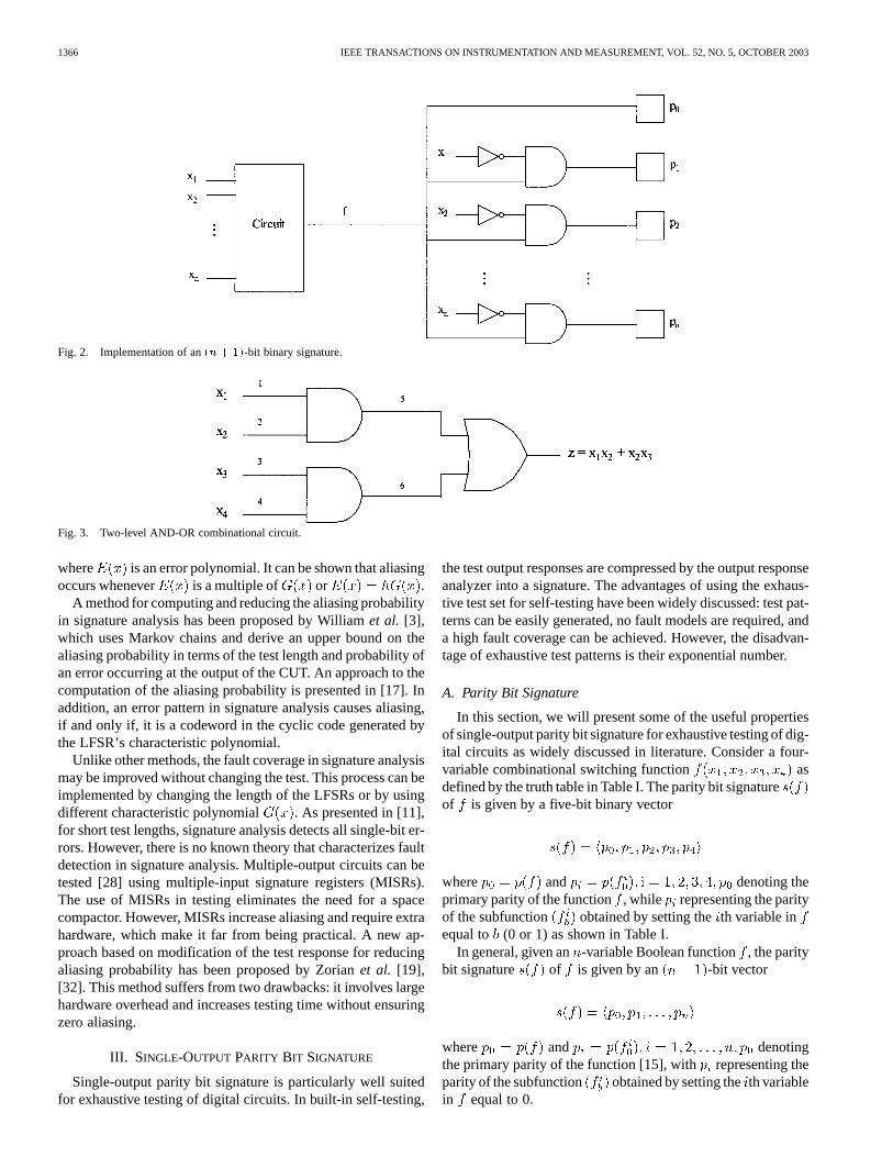
Fig. 2. Implementation of an(n + 1)-bit binary signature.
Fig. 3. Two-level AND-OR combinational circuit.
where is an error polynomial. It can be shown that aliasingoccurs whenever is a multiple of or .
A method for computing and reducing the aliasing probabilityin signature analysis has been proposed by Williamet al. [3],which uses Markov chains and derive an upper bound on thealiasing probability in terms of the test length and probability ofan error occurring at the output of the CUT. An approach to thecomputation of the aliasing probability is presented in [17]. Inaddition, an error pattern in signature analysis causes aliasing,if and only if, it is a codeword in the cyclic code generated bythe LFSR’s characteristic polynomial.
Unlike other methods, the fault coverage in signature analysismay be improved without changing the test. This process can beimplemented by changing the length of the LFSRs or by usingdifferent characteristic polynomial . As presented in [11],for short test lengths, signature analysis detects all single-bit er-rors. However, there is no known theory that characterizes faultdetection in signature analysis. Multiple-output circuits can betested [28] using multiple-input signature registers (MISRs).The use of MISRs in testing eliminates the need for a spacecompactor. However, MISRs increase aliasing and require extrahardware, which make it far from being practical. A new ap-proach based on modification of the test response for reducingaliasing probability has been proposed by Zorianet al. [19],[32]. This method suffers from two drawbacks: it involves largehardware overhead and increases testing time without ensuringzero aliasing.
III. SINGLE-OUTPUT PARITY BIT SIGNATURE
Single-output parity bit signature is particularly well suitedfor exhaustive testing of digital circuits. In built-in self-testing,
the test output responses are compressed by the output responseanalyzer into a signature. The advantages of using the exhaus-tive test set for self-testing have been widely discussed: test pat-terns can be easily generated, no fault models are required, anda high fault coverage can be achieved. However, the disadvan-tage of exhaustive test patterns is their exponential number.
A. Parity Bit Signature
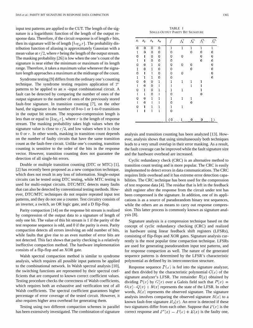
In this section, we will present some of the useful propertiesof single-output parity bit signature for exhaustive testing of dig-ital circuits as widely discussed in literature. Consider a four-variable combinational switching function asdefined by the truth table in Table I. The parity bit signatureof is given by a five-bit binary vector
where and denoting theprimary parity of the function , while representing the parityof the subfunction obtained by setting theth variable inequal to (0 or 1) as shown in Table I.
In general, given an-variable Boolean function, the paritybit signature of is given by an -bit vector
where and denotingthe primary parity of the function [15], with representing theparity of the subfunction obtained by setting theth variablein equal to 0.
DAS et al.: PARITY BIT SIGNATURE IN RESPONSE DATA COMPACTION 1367
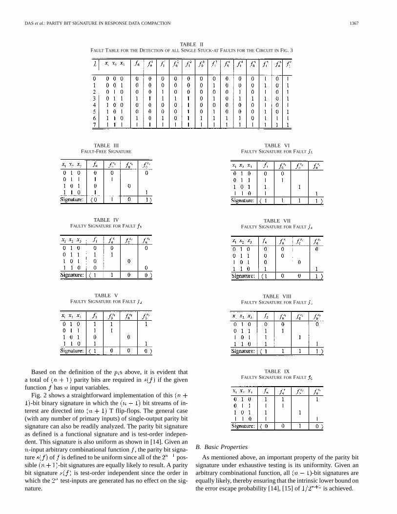
TABLE IIFAULT TABLE FOR THE DETECTION OF ALL SINGLE STUCK-AT FAULTS FOR THECIRCUIT IN FIG. 3
TABLE IIIFAULT-FREE SIGNATURE
TABLE IVFAULTY SIGNATURE FORFAULT f
TABLE VFAULTY SIGNATURE FORFAULT f
Based on the definition of the s above, it is evident thata total of parity bits are required in if the givenfunction has input variables.
Fig. 2 shows a straightforward implementation of this-bit binary signature in which the bit streams of in-
terest are directed into T flip-flops. The general case(with any number of primary inputs) of single-output parity bitsignature can also be readily analyzed. The parity bit signatureas defined is a functional signature and is test-order indepen-dent. This signature is also uniform as shown in [14]. Given an
-input arbitrary combinational function, the parity bit signa-ture of is defined to be uniform since all of the pos-sible -bit signatures are equally likely to result. A paritybit signature is test-order independent since the order inwhich the test-inputs are generated has no effect on the sig-nature.
TABLE VIFAULTY SIGNATURE FORFAULT f
TABLE VIIFAULTY SIGNATURE FORFAULT f
TABLE VIIIFAULTY SIGNATURE FORFAULT f
TABLE IXFAULTY SIGNATURE FORFAULT f
B. Basic Properties
As mentioned above, an important property of the parity bitsignature under exhaustive testing is its uniformity. Given anarbitrary combinational function, all )-bit signatures areequally likely, thereby ensuring that the intrinsic lower bound onthe error escape probability [14], [15] of is achieved.

1368 IEEE TRANSACTIONS ON INSTRUMENTATION AND MEASUREMENT, VOL. 52, NO. 5, OCTOBER 2003
TABLE XFAULT-FREE SIGNATURE
TABLE XIFAULTY SIGNATURE FORFAULT f
TABLE XIIFAULTY SIGNATURE FORFAULT f
In the following discussion, we present some of the basicproperties of parity functions [14] that are relevant in the con-text of fault detection using single-output parity bit signature,and also multiple-output parity bit signature as discussed next.
Property 1: If a switching function ofvariables is independent of a variable, thenits parity relative to will always be 0.
Example: Consider a 3-variable function.
Now, can be expressed as .This function is obviously independent of the variableandits parity .
Property 2: On the other hand, if a switching functionof variables is a depen-
dent function of all its variables, then its parity .Property 3: If a switching function of
variables is comprised of a single canonicalproduct term or minterm, then its parity .
Example: Consider a function . Itsparity .
Property 4: If a switching function ofvariables is comprised of a single canonicalsum of all its variables or a maxterm, then its parity .
Example: Consider a function ;then, in minterm form is given by
. Thus, .Property 5: If a switching function of
variables is specified as the XOR sum of all itsvariables, then its parity .
TABLE XIIIFAULTY SIGNATURE FORFAULT f
TABLE XIVFAULTY SIGNATURE FORFAULT f
TABLE XVFAULTY SIGNATURE FORFAULT f
TABLE XVIFAULTY SIGNATURE FORFAULT f
Example: Consider a 3-variable function.
This function is an odd parity function and can be expressed as. Obviously, its parity
.Property 6: If a switching function ofvariables is the complement of a function
, then .Example: Consider the 3-variable function
, such that
.Obviously, .
Property 7: If a switching function isobtained by complementing a variable of the function
, then .Property 8: If a switching function is
obtained by interchange of two variables of a function, then .
DAS et al.: PARITY BIT SIGNATURE IN RESPONSE DATA COMPACTION 1369
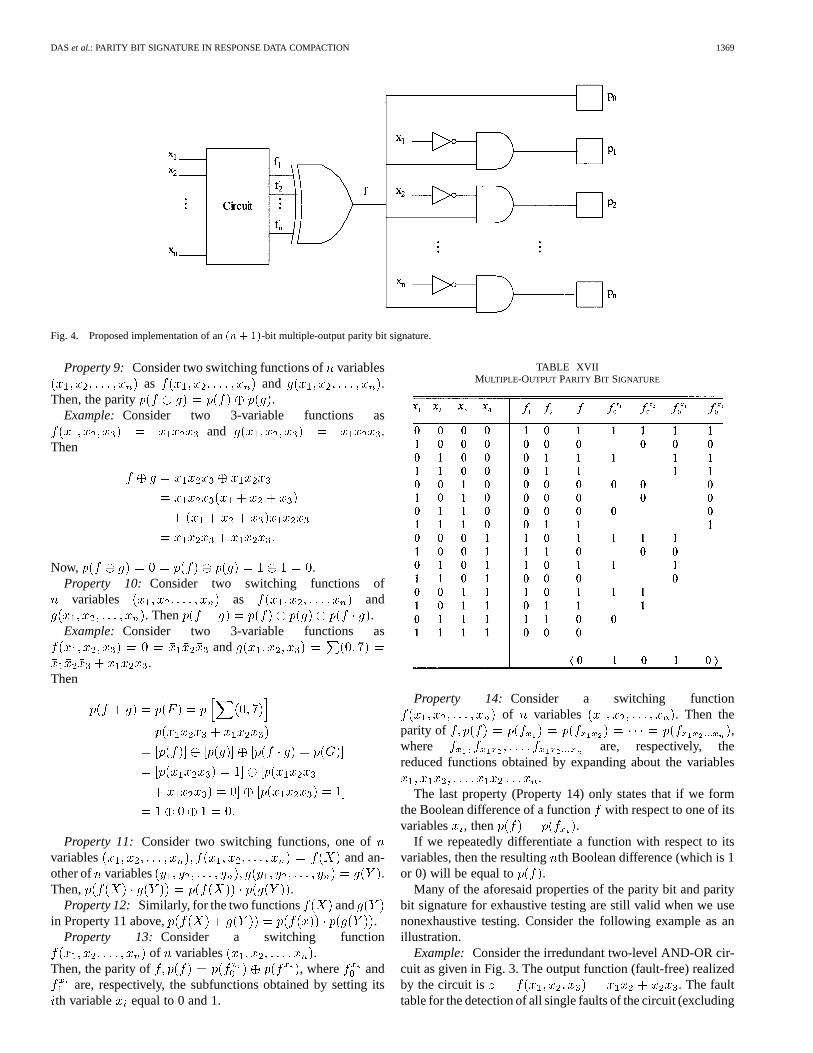
Fig. 4. Proposed implementation of an(n + 1)-bit multiple-output parity bit signature.
Property 9: Consider two switching functions ofvariablesas and .
Then, the parity .Example: Consider two 3-variable functions as
and .Then
Now, .Property 10: Consider two switching functions of
variables as and. Then .
Example: Consider two 3-variable functions asand
.Then
Property 11: Consider two switching functions, one ofvariables and an-other of variables .Then, .
Property 12: Similarly, for the two functions andin Property 11 above, .
Property 13: Consider a switching functionof variables .
Then, the parity of , where andare, respectively, the subfunctions obtained by setting its
th variable equal to 0 and 1.
TABLE XVIIMULTIPLE-OUTPUT PARITY BIT SIGNATURE
Property 14: Consider a switching functionof variables . Then the
parity of ,where are, respectively, thereduced functions obtained by expanding about the variables
.The last property (Property 14) only states that if we form
the Boolean difference of a functionwith respect to one of itsvariables , then .
If we repeatedly differentiate a function with respect to itsvariables, then the resultingth Boolean difference (which is 1or 0) will be equal to .
Many of the aforesaid properties of the parity bit and paritybit signature for exhaustive testing are still valid when we usenonexhaustive testing. Consider the following example as anillustration.
Example: Consider the irredundant two-level AND-OR cir-cuit as given in Fig. 3. The output function (fault-free) realizedby the circuit is . The faulttable for the detection of all single faults of the circuit (excluding
1370 IEEE TRANSACTIONS ON INSTRUMENTATION AND MEASUREMENT, VOL. 52, NO. 5, OCTOBER 2003
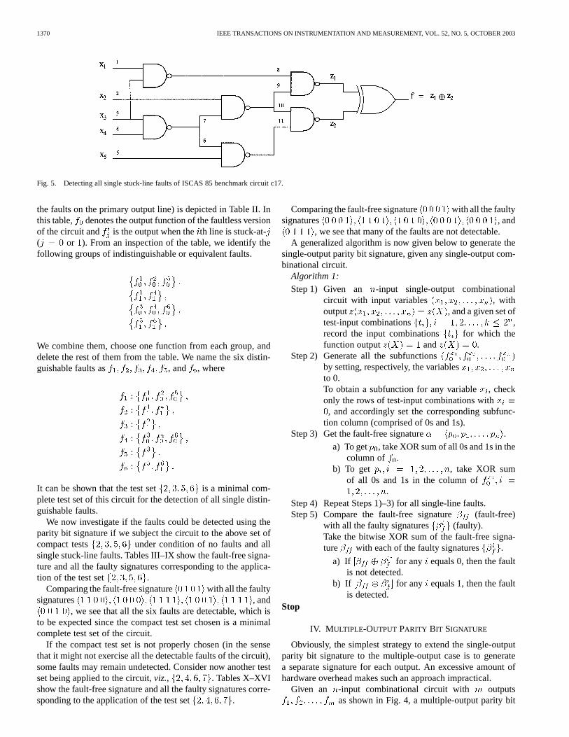
Fig. 5. Detecting all single stuck-line faults of ISCAS 85 benchmark circuit c17.
the faults on the primary output line) is depicted in Table II. Inthis table, denotes the output function of the faultless versionof the circuit and is the output when theth line is stuck-at-( or ). From an inspection of the table, we identify thefollowing groups of indistinguishable or equivalent faults.
We combine them, choose one function from each group, anddelete the rest of them from the table. We name the six distin-guishable faults as , and , where
It can be shown that the test set is a minimal com-plete test set of this circuit for the detection of all single distin-guishable faults.
We now investigate if the faults could be detected using theparity bit signature if we subject the circuit to the above set ofcompact tests under condition of no faults and allsingle stuck-line faults. Tables III–IX show the fault-free signa-ture and all the faulty signatures corresponding to the applica-tion of the test set .
Comparing the fault-free signature with all the faultysignatures , and
, we see that all the six faults are detectable, which isto be expected since the compact test set chosen is a minimalcomplete test set of the circuit.
If the compact test set is not properly chosen (in the sensethat it might not exercise all the detectable faults of the circuit),some faults may remain undetected. Consider now another testset being applied to the circuit,viz., . Tables X–XVIshow the fault-free signature and all the faulty signatures corre-sponding to the application of the test set .
Comparing the fault-free signature with all the faultysignatures , and
, we see that many of the faults are not detectable.A generalized algorithm is now given below to generate the
single-output parity bit signature, given any single-output com-binational circuit.
Algorithm 1:
Step 1) Given an -input single-output combinationalcircuit with input variables , withoutput , and a given set oftest-input combinations ,record the input combinations for which thefunction output and .
Step 2) Generate all the subfunctionsby setting, respectively, the variablesto 0.To obtain a subfunction for any variable, checkonly the rows of test-input combinations with, and accordingly set the corresponding subfunc-
tion column (comprised of 0s and 1s).Step 3) Get the fault-free signature .
a) To get , take XOR sum of all 0s and 1s in thecolumn of .
b) To get , take XOR sumof all 0s and 1s in the column of
.Step 4) Repeat Steps 1)–3) for all single-line faults.Step 5) Compare the fault-free signature (fault-free)
with all the faulty signatures (faulty).Take the bitwise XOR sum of the fault-free signa-ture with each of the faulty signatures .
a) If for any equals 0, then the faultis not detected.
b) If for any equals 1, then the faultis detected.
Stop
IV. M ULTIPLE-OUTPUT PARITY BIT SIGNATURE
Obviously, the simplest strategy to extend the single-outputparity bit signature to the multiple-output case is to generatea separate signature for each output. An excessive amount ofhardware overhead makes such an approach impractical.
Given an -input combinational circuit with outputsas shown in Fig. 4, a multiple-output parity bit
DAS et al.: PARITY BIT SIGNATURE IN RESPONSE DATA COMPACTION 1371
TABLE XVIIIFAULT-FREE SIGNATURE
TABLE XIXFAULTY SIGNATURE FORFAULT f
TABLE XXFAULTY SIGNATURE FORFAULT f
signature can be generated by first XORing all the outputs toproduce a new output and then feeding this new output to asingle-output parity bit signature generator. This signature canbe represented as a binary vector as
Table XVII is an example of multiple-output parity bit signaturegeneration.
It was shown in [14], [15] that the proposed method of sig-nature generation under exhaustive testing evidently makes thesignature test-order independent. The uniformity property of thesignature similarly holds for the general case of multiple-outputfunctions, and is proved in [15] using a shorter and more elegantmethod based on linear algebraic techniques and properties ofGF(2), and is omitted here [16].
In this paper we investigate the possibility of detecting allsingle stuck-line faults in digital circuits by using parity bit sig-nature not coupled with an exhaustive set of tests, but rather,nonexhaustive set of tests. Before we explore the feasibility ofsuch an approach in general, let us first demonstrate if some ofthe earlier discussed desirable properties of such a signature willstill be valid while using nonexhaustive set of tests. These arediscussed below in the form of properties and theorem.
Property 15: A parity bit signature (single-output or mul-tiple-output) in the context of nonexhaustive testing of digitalcircuits is a functional signature.
TABLE XXIFAULTY SIGNATURE FORFAULT f
TABLE XXIIFAULTY SIGNATURE FORFAULT f
TABLE XXIIIFAULTY SIGNATURE FORFAULT f
This is obvious since irrespective of whether we use exhaus-tive or nonexhaustive testing, the signature remains independentof the particular implementation involved.
Property 16: A parity bit signature (single-output or mul-tiple-output) in the context of nonexhaustive testing of digitalcircuits is test-order independent.
The order in which the independent tests in the compact testsets are generated and applied has no effect on the signature.
Property 17: A parity bit signature (single-output or mul-tiple-output) in the context of nonexhaustive testing of digitalcircuits is easily implementable and can be shown to be effec-tive for single fault detection.
The property evidently follows based on the properties ofparity bit signature and also of parity bits as discussed earlier.
Theorem 1: A parity bit signature (single-output or multiple-output) in the context of nonexhaustive testing of digital circuitsis obviously not uniform in the sense that given any arbitrarycombinational switching function, all signature bit patterns in
are not equally likely to result.Proof: Since the different s in are
each derived not on exhaustive application of all theinputcombinations or ordered-tuples, it follows rather obviouslythat the th parity bit in cannot be equal to0 or 1 with equal probability, thus providing a signature which isnot uniform, a property unfortunately shared by many countingtechniques.
1372 IEEE TRANSACTIONS ON INSTRUMENTATION AND MEASUREMENT, VOL. 52, NO. 5, OCTOBER 2003
TABLE XXIVFAULTY SIGNATURE FORFAULT f
TABLE XXVFAULTY SIGNATURE FORFAULT f
TABLE XXVIFAULTY SIGNATURE FORFAULT f
Let us first illustrate the feasibility of the proposed approachconsidering the following example.
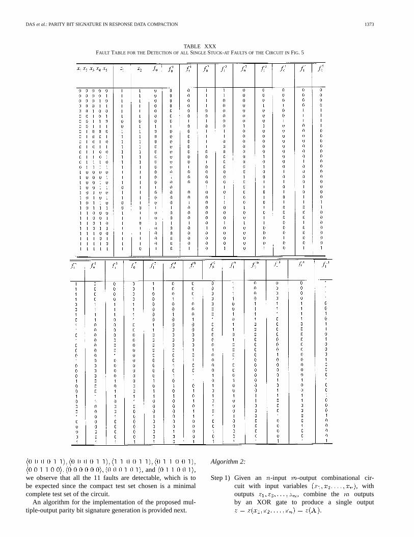
Example: The circuit in Fig. 5 is the first circuit c17 of theISCAS 85 combinational benchmark circuits. We obtain a singleoutput from this circuit by XORing its two outputs and .Table XXX is the fault table for the detection of all single faultsof the circuit at the output (faults on lines , and arenot considered) when all the input patterns are applied.
In this table, denotes the output function of the faultlessversion of the circuit and is the output when theth line isstuck-at- ( or ). From an inspection of the table, weidentify the following groups of indistinguishable or equivalentfaults:
We combine them, choose one function from each group, anddelete the rest of them from the table. We name the 11 distin-
TABLE XXVIIFAULTY SIGNATURE FORFAULT f
TABLE XXVIIIFAULTY SIGNATURE FORFAULT f
TABLE XXIXFAULTY SIGNATURE FORFAULT f
guishable faults as , and ,where
It can be shown that the test set is a minimalcomplete test set of this circuit for the detection of all singledistinguishable faults.
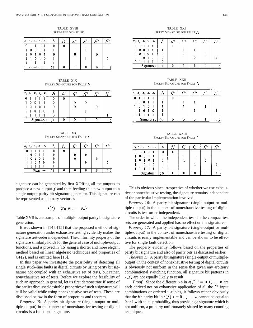
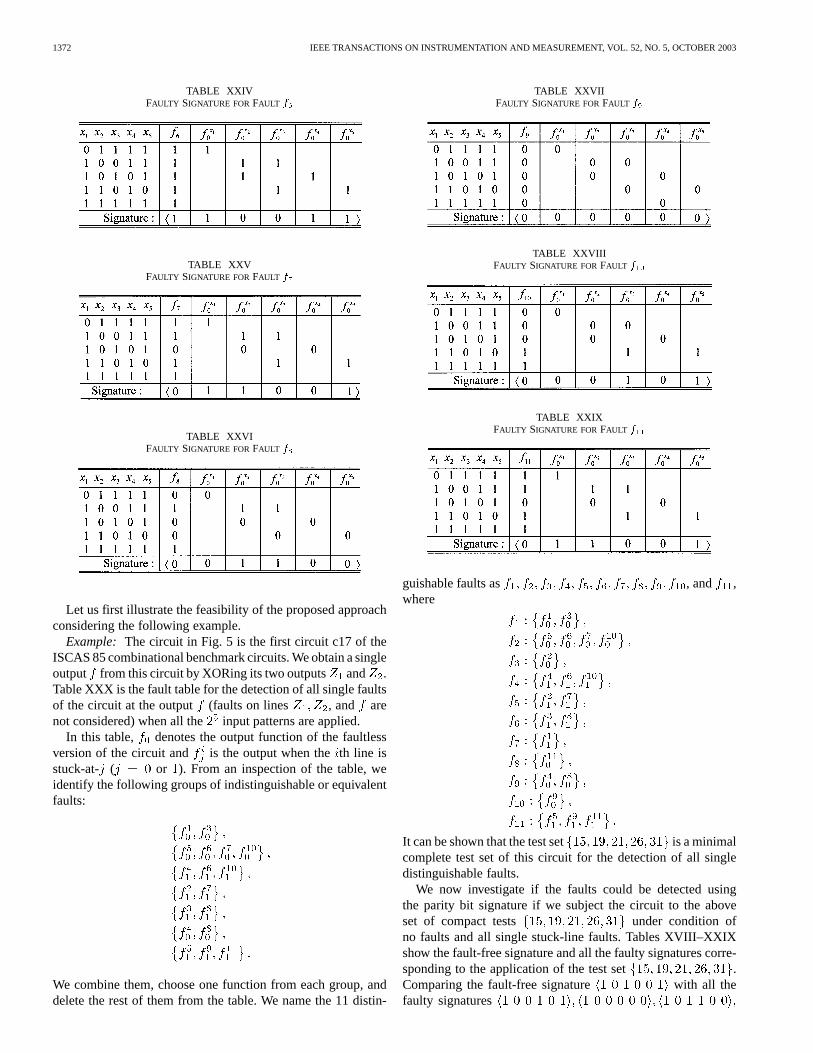
We now investigate if the faults could be detected usingthe parity bit signature if we subject the circuit to the aboveset of compact tests under condition ofno faults and all single stuck-line faults. Tables XVIII–XXIXshow the fault-free signature and all the faulty signatures corre-sponding to the application of the test set .Comparing the fault-free signature with all thefaulty signatures
DAS et al.: PARITY BIT SIGNATURE IN RESPONSE DATA COMPACTION 1373
TABLE XXXFAULT TABLE FOR THE DETECTION OF ALL SINGLE STUCK-AT FAULTS OF THE CIRCUIT IN FIG. 5
, and ,we observe that all the 11 faults are detectable, which is tobe expected since the compact test set chosen is a minimalcomplete test set of the circuit.
An algorithm for the implementation of the proposed mul-tiple-output parity bit signature generation is provided next.
Algorithm 2:
Step 1) Given an -input -output combinational cir-cuit with input variables , withoutputs , combine the outputsby an XOR gate to produce a single output
.
1374 IEEE TRANSACTIONS ON INSTRUMENTATION AND MEASUREMENT, VOL. 52, NO. 5, OCTOBER 2003
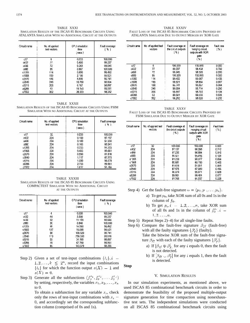
TABLE XXXISIMULATION RESULTS OF THEISCAS 85 BENCHMARK CIRCUITS USING
ATALANTA S IMULATOR WITH NO ADDITIONAL CIRCUIT AT THE OUTPUTS
TABLE XXXIISIMULATION RESULTS OF THEISCAS 85 BENCHMARK CIRCUITS USING FSIM
SIMULATOR WITH NO ADDITIONAL CIRCUIT AT THE OUTPUTS
TABLE XXXIIISIMULATION RESULTS OF THEISCAS 85 BENCHMARK CIRCUITS USING
COMPACTEST SIMULATOR WITH NO ADDITIONAL CIRCUIT
AT THE OUTPUTS
Step 2) Given a set of test-input combinations, record the input combinations
for which the function output and.
Step 3) Generate all the subfunctionsby setting, respectively, the variablesto 0.To obtain a subfunction for any variable, checkonly the rows of test-input combinations with, and accordingly set the corresponding subfunc-
tion column (comprised of 0s and 1s).
TABLE XXXIVFAULT LOSS OF THEISCAS 85 BENCHMARK CIRCUITS PROVIDED BY
ATALANTA S IMULATOR DUE TO OUTPUT MERGER BYXOR GATE
TABLE XXXVFAULT LOSS OF THEISCAS 85 BENCHMARK CIRCUITS PROVIDED BY
FSIM SIMULATOR DUE TO OUTPUT MERGER BYXOR GATE
Step 4) Get the fault-free signature .
a) To get , take XOR sum of all 0s and 1s in thecolumn of .
b) To get , take XOR sumof all 0s and 1s in the column of
.Step 5) Repeat Steps 2)–4) for all single-line faults.Step 6) Compare the fault-free signature (fault-free)
with all the faulty signatures (faulty).Take the bitwise XOR sum of the fault-free signa-ture with each of the faulty signatures .
a) If for any equals 0, then the faultis not detected.
b) If for any equals 1, then the faultis detected.
Stop
V. SIMULATION RESULTS
In our simulation experiments, as mentioned above, weused ISCAS 85 combinational benchmark circuits in order todemonstrate the feasibility of the proposed multiple-outputsignature generation for time compaction using nonexhaus-tive test sets. The independent simulations were conductedon all ISCAS 85 combinational benchmark circuits using

DAS et al.: PARITY BIT SIGNATURE IN RESPONSE DATA COMPACTION 1375
TABLE XXXVIFAULT LOSS OF THEISCAS 85 BENCHMARK CIRCUITS PROVIDED BY
COMPACTEST SIMULATOR DUE TO OUTPUT MERGER BYXOR GATE
TABLE XXXVIISIMULATION RESULTS OF THEISCAS 85 BENCHMARK CIRCUITS USING
ATALANTA/FSIM SIMULATOR WITH TIME COMPACTION
TABLE XXXVIIISIMULATION RESULTS OF THEISCAS 85 BENCHMARK CIRCUITS USING
COMPACTEST SIMULATOR FOR TIME COMPACTION
ATALANTA, FSIM, and COMPACTEST simulators. TheATALANTA [34] was used to generate the fault-free outputstreams required to construct the CUT signatures and to testthe benchmark circuits using reduced or compact test sets.FSIM [35] was used as a fault simulation program to generatepseudorandom test sets for testing the benchmark circuits. TheCOMPACTEST [36] program was used to generate the reducedtest sets that detect most detectable single stuck-line faults forall benchmark circuits.
TABLE XXXIXFAULT LOSS OF THEISCAS 85 BENCHMARK CIRCUITS USING
ATALANTA/FSIM SIMULATOR FOR TIME COMPACTION
TABLE XLFAULT LOSS OF THEISCAS 85 BENCHMARK CIRCUITS USING
COMPACTEST SIMULATOR FOR TIME COMPACTION
TABLE XLIHARDWARE OVERHEAD ESTIMATES
The ATALANTA and FSIM programs were simulated on aSUN SPARC 5 workstation, while the COMPACTEST programwas implemented on an IBM AIX machine. For each ISCAS 85combinational benchmark circuit, we determined the number oftest vectors used to construct the required signatures, CPU sim-ulation time taken for the construction, together with the per-centage fault coverage. The fault coverage was first computedat the output of the benchmark circuits alone without any ad-ditional circuits, next when the circuit outputs were merged byXOR gate, and was finally computed when the XOR gate outputwas fed to a parity bit signature generator, that is, at the outputof the CUT together with the compression network. The com-bination of these simulation results provides a clearer picture

1376 IEEE TRANSACTIONS ON INSTRUMENTATION AND MEASUREMENT, VOL. 52, NO. 5, OCTOBER 2003
TABLE XLIIFAULT-FREE AND FAULTY SIGNATURES FORc432 BENCHMARK CIRCUIT USING
ATALANTA/FSIM SIMULATOR WITH TIME COMPACTION
in determining the fault loss introduced by the XOR gate, andmultiple-output parity bit signature generator which includesthe XOR gate as part of its overall hardware. The area over-head introduced by the multiple-output signature generator forall simulated benchmark circuits using ATALANTA, FSIM, andCOMPACTEST was determined as well. The experimental re-sults are summarized in the following sets of tables.
Tables XXXI–XXXIII show the results of simulation onthe ISCAS 85 benchmark circuits using ATALANTA, FSIM,and COMPACTEST simulators, respectively, with no addi-tional circuits at the outputs. From these results we see thatATALANTA and COMPACTEST provide almost similar faultcoverage results for all the benchmark circuits, being muchhigher than the corresponding values provided by FSIM, whileCOMPACTEST provides the highest CPU simulation time forall the circuits except c17. Tables XXXIV–XXXVI, on the otherhand, show the simulation results on the ISCAS circuits usingATALANTA, FSIM, and COMPACTEST simulators, respec-tively, when the outputs of each circuit are merged by an XORgate. Here, as is evident, ATALANTA and COMPACTESTprovide best results in terms of fault coverage compared toFSIM; fault loss due to merger by XOR gate is also computed
TABLE XLIIIFAULT-FREE AND FAULTY SIGNATURES FORc432 BENCHMARK CIRCUIT USING
COMPACTEST SIMULATOR WITH TIME COMPACTION
in these tables. Tables XXXVII and XXXVIII provide resultson simulation using, respectively, ATALANTA/FSIM andCOMPACTEST with time compression (viz. XOR gate fol-lowed by parity bit signature generator), while Tables XXXIXand XL show the corresponding fault loss values, respectively,for ATALANTA/FSIM and COMPACTEST. From the experi-mental results, we might conclude that time compaction resultsin better CPU simulation time in general. Also, in all cases, weobtained lower fault coverage for the circuits, which is to beexpected.
The hardware overhead estimates for all the ISCAS 85 bench-mark circuits are given in Table XLI. The estimates were foundto be as small as 0.7–7.3% in most cases, with a value of 14.3%for the c17 benchmark circuit only.
A. Fault-Free and Faulty Signatures for Circuit c432
Tables XLII and XLIII provide the fault-free signature as wellas faulty signatures for the second benchmark circuit c432 com-prised of 160 gates, 36 primary inputs, and seven primary out-puts while using, respectively, ATALANTA/FSIM and COM-PACTEST. In the simulation experiment, we use one XOR gate

DAS et al.: PARITY BIT SIGNATURE IN RESPONSE DATA COMPACTION 1377
TABLE XLIVSIMULATION RESULTS OF THEISCAS 85 BENCHMARK CIRCUITS USING
ATALANTA/FSIM SIMULATOR FOR SPACE-TIME COMPACTION
TABLE XLVSIMULATION RESULTS OF THEISCAS 85 BENCHMARK CIRCUITS USING
COMPACTEST SIMULATOR FOR SPACE-TIME COMPACTION
to merge all the outputs of the circuit to a single output. How-ever, for large circuits such as c2670, c7552, we use more thanone XOR gate to group two, three, or four outputs for merger atone time.
VI. SPACE-TIME COMPACTION
Instead of using only time compaction for the multiple-outputcircuits (that is, multiple-output parity bit signature generator),it is also possible to first use space compression which isultimately followed by time compaction. In the present section,we discuss the outcomes of such experimentation on ISCAS85 benchmark circuits. In our experimentation, we carry outthe design of space compressors for the ISCAS 85 benchmarkcircuits following the optimal mergeability criteria as devel-oped in [32] to merge suitable sets of candidate outputs ofthe benchmark circuits to single outputs and then use paritybit time compaction. The details for the design of such spacecompressors comprised of AND (NAND), OR (NOR), andXOR (XNOR) gates, in general, could be found in [29]–[32]and are thus omitted here. The results of simulation on ISCAS85 benchmark circuits using this kind of space-time compactionare given in Tables XLIV–XLVII, using ATALANTA/FSIMand COMPACTEST, respectively. These results are evidentlyself-explanatory.
TABLE XLVIFAULT LOSS OF THEISCAS 85 BENCHMARK CIRCUITS USING
ATALANTA/FSIM SIMULATOR FOR SPACE-TIME COMPACTION
TABLE XLVIIFAULT LOSS OF THEISCAS 85 BENCHMARK CIRCUITS USING COMPACTEST
SIMULATOR FOR SPACE-TIME COMPACTION
VII. CONCLUDING REMARKS
The implementation of time-efficient BIST support hardwareis of great importance in the synthesis of complex digital in-tegrated circuits. This paper reports on developing compres-sion techniques of test data outputs for digital integrated cir-cuits that facilitate the design of such time-efficient BIST sup-port hardware using compact test sets. Specifically, extendingthe concept of multiple-output parity bit signature generationas suggested for exhaustive testing of VLSI circuits recently byJone and Das [15], the subject paper proposes a multiple-outputparity bit signature generation method for use with nonexhaus-tive or compact test sets in testing digital integrated circuits.The suggested compaction technique, as evidenced by extensivesimulation experiments on ISCAS 85 combinational benchmarkcircuits using fault simulation programs FSIM, ATALANTA,and COMPACTEST, provides a high fault coverage for singlestuck-line faults, with low CPU simulation time, and acceptablearea overhead for the compactor. As is obvious, the design ofzero-aliasing compressors was not our priority; we rather en-deavored in the paper to reinforce the connection between theinput test sets, their lengths, and their reduction into recom-mended algorithms in the construction of the compaction trees.Information loss [37] may not be completely avoided when thesize of all output responses is reduced. Therefore, depending onthe amount of information loss, the corresponding time com-pactor design will be affected as well. In our design experi-ments, we used the reduced test sets provided by ATALANTA
1378 IEEE TRANSACTIONS ON INSTRUMENTATION AND MEASUREMENT, VOL. 52, NO. 5, OCTOBER 2003
and COMPACTEST to simulate all the ISCAS 85 combina-tional benchmark circuits. Even though these reduced input testsets arenot the minimal test sets needed to ensure a 100% faultcoverage, experimental results indicate that our designed mul-tiple-output parity bit signature generators are comparable inall respects with conventional space-time compression, usuallyconsidered ideal for multiple-output combinational circuits.
REFERENCES
[1] P. H. Bardell, W. H. McAnney, and J. Savir,Built-In Test for VLSI: Pseu-dorandom Technique. New York: Wiley, 1987.
[2] S. Mourad and Y. Zorian,Principles of Testing Electronic Sys-tems. New York: Wiley, 2000.
[3] T. W. Williams and K. P. Parker, “Testing logic networks and design fortestability,”Computer, vol. 21, pp. 9–21, Oct. 1979.
[4] E. J. McCluskey, “Built-in self-test techniques,”IEEE Design TestComput., vol. 2, pp. 21–28, Apr. 1985.
[5] R. G. Daniels and W. B. Bruce, “Built-in self-test trends in Motorolamicroprocessors,”IEEE Design Test Comput., vol. 2, pp. 64–71, Apr.1985.
[6] J. P. Hayes, “Check sum methods for test data compression,”J. DesignAutomat. Fault-Tolerant Comput., vol. 1, pp. 3–7, Jan. 1976.
[7] , “Transition count testing of combinational logic circuits,”IEEETrans. Comput., vol. C-25, pp. 613–620, June 1976.
[8] R. A. Frohwerk, “Signature analysis—A new digital field servicemethod,”Hewlett-Packard J., vol. 28, pp. 2–8, May 1977.
[9] J. Savir, “Syndrome-testable design of combinational circuits,”IEEETrans. Comput., vol. C-29, pp. 442–451, June 1980.
[10] A. K. Susskind, “Testing by verifying Walsh coefficients,”IEEE Trans.Comput., vol. C-32, pp. 198–201, Feb. 1983.
[11] N. R. Saxena and J. P. Robinson, “A unified view of test response com-pression methods,”IEEE Trans. Comput., vol. C-36, pp. 94–99, Jan.1987.
[12] T. W. Williams, W. Daehn, M. Gruetzner, and C. W. Starke, “Aliasingerrors in signature analysis registers,”IEEE Design Test Comput., vol.4, pp. 39–45, Apr. 1987.
[13] N. R. Saxena and J. P. Robinson, “Syndrome and transition count are un-correlated,”IEEE Trans. Inform. Theory, vol. 34, pp. 64–69, Jan. 1988.
[14] S. B. Akers, “A parity bit signature for exhaustive testing,”IEEE Trans.Comput. Aided Design, vol. 7, pp. 333–338, Mar. 1988.
[15] W. B. Jone and S. R. Das, “Multiple-output parity bit signature forexhaustive testing,”J. Electron. Testing: Theory Applicat., vol. 1, pp.175–178, Mar. 1990.
[16] N. S. Khabra and S. R. Das, “Multiform partial symmetry and parityfunctions,”IEEE Trans. Comput., vol. C-22, p. 804, Aug. 1973.
[17] D. K. Pradhan and S. K. Gupta, “A new framework for designing andanalyzing BIST techniques and zero aliasing compression,”IEEE Trans.Comput., vol. C-40, pp. 743–763, June 1991.
[18] K. Chakrabarty and J. P. Hayes, “Cumulative balance testing of logiccircuits,” IEEE Trans. VLSI Syst., vol. 3, pp. 72–83, Mar. 1995.
[19] K. Chakrabarty, “Test Response Compaction for Built—In Self Testing,”Ph.D. Dissertation, Dept. Computer Science and Engineering, Univ. ofMichigan, Ann Arbor, MI, 1995.
[20] K. K. Saluja and M. Karpovsky, “Testing computer hardware throughcompression in space and time,” inProc. Int. Test Conf., 1983, pp.83–88.
[21] Y. Zorian and V. K. Agarwal, “A general scheme to optimize errormasking in built-in self testing,” inProc. Int. Symp. Fault-TolerantComput., 1986, pp. 410–415.
[22] Y. K. Li and J. P. Robinson, “Space compression method with output datamodification,”IEEE Trans. Comput. Aided Design, vol. 6, pp. 290–294,Mar. 1987.
[23] S. M. Reddy, K. K. Saluja, and M. G. Karpovsky, “Data compressiontechnique for test responses,”IEEE Trans. Comput., vol. C-37, pp.1151–1156, Sept. 1988.
[24] M. Karpovsky and P. Nagvajara, “Optimal robust compression of testresponses,”IEEE Trans. Comput., vol. C-39, pp. 138–141, Jan. 1990.
[25] W.-B. Jone and S. R. Das, “Space compression method for built-in self-testing of VLSI circuits,”Int. J. Comput. Aided VLSI Design, vol. 3, pp.309–322, Sept. 1991.
[26] S. R. Das, H. T. Ho, W. B. Jone, and A. R. Nayak, “An improved outputcompaction technique for built-in self-test in VLSI circuits,” inProc.Int. Conf. VLSI Design, 1994, pp. 403–407.
[27] K. Chakrabarty and J. P. Hayes, “Efficient test response compression formultiple-output circuits,” inProc. Int. Test Conf., 1994, pp. 501–510.
[28] J. Savir, “Reducing the MISR size,”IEEE Trans. Comput., vol. C-45,pp. 930–938, Aug. 1996.
[29] S. R. Das, E. M. Petriu, T. Barakat, M. H. Assaf, and A. R. Nayak,“Space compaction under generalized mergeability,”IEEE Trans. In-strum. Meas., vol. 47, pp. 1283–1293, Oct. 1998.
[30] S. R. Das, T. F. Barakat, E. M. Petriu, M. H. Assaf, and K. Chakrabarty,“Space compression revisited,”IEEE Trans. Instrum. Meas., vol. 49, pp.690–705, June 2000.
[31] J. Y. Liang, “Response Data Compaction in BIST Under GeneralizedMergeability Based on Switching Theory Formulation and Utilizing aNew Measure of Failure Probability,” M.A.Sc. Thesis, School of In-formation Technology and Engineering, Univ. of Ottawa, Ottawa, ON,Canada, Sept. 2000.
[32] S. R. Das, C. V. Ramamoorthy, M. H. Assaf, E. M. Petriu, and W.-B.Jone, “Fault tolerance in systems design in VLSI using data compressionunder constraints of failure probabilities,”IEEE Trans. Instrum. Meas.,vol. 50, pp. 1725–1747, Dec. 2001.
[33] M. R. Garey and D. S. Johnson,Computers and Intractability: A Guideto the Theory of NP-Completeness. New York: W. H. Freeman, 1979.
[34] H. K. Lee and D. S. Ha, “On the Generation of Test Patterns for Com-binational Circuits,” Dept. Electrical Engineering, Virginia PolytechnicInstitute and State Univ., Blacksburg, VA, Tech. Rep. 12-93, 1993.
[35] , “An efficient forward fault simulation algorithm based on the par-allel pattern single fault propagation,” inProc. Int. Test Conf., 1991, pp.946–955.
[36] I. Pomeranz, L. N. Reddy, and S. M. Reddy, “COMPACTEST: A methodto generate compact test sets for combinational circuits,” inProc. Int.Test Conf., 1991, pp. 194–203.
[37] M. Sahinoglu, C. Bayrak, and T. Cummings, “High assurance softwaretesting in business and DoD,”Trans. Soc. Design Process Sci., vol. 6,pp. 107–114, June 2002.
Sunil R. Das (M’70–SM’90–F’94) received theB.Sc. (Honors) degree in physics and the M.Sc.(Tech.) and Ph.D. degrees in radiophysics andelectronics from the University of Calcutta, Calcutta,West Bengal, India.
He is a Professor of Electrical and Computer En-gineering at the School of Information Technologyand Engineering, University of Ottawa, Ottawa,ON, Canada. He previously held academic andresearch positions with the Department of ElectricalEngineering and Computer Sciences, Computer
Science Division, University of California, Berkeley, the Center for ReliableComputing (CRC), Computer Systems Laboratory, Department of ElectricalEngineering, Stanford University, Stanford, CA (on sabbatical leave), theInstitute of Computer Engineering, National Chiao Tung University, Hsinchu,Taiwan, R.O.C., and the Center of Advanced Study (CAS), Institute of Radio-physics and Electronics, University of Calcutta. He has published extensiblyin the areas of switching and automata theory, digital logic design, thresholdlogic, fault-tolerant computing, microprogramming and microarchitecture,microcode optimization, applied theory of graphs, and combinatorics. Hehas edited, jointly with P. K. Srimani, a book entitledDistributed MutualExclusion Algorithms(Los Alamitos, CA: IEEE Computer Society Press,1992). He is coauthor, with C. L. Sheng, of a text on digital logic design,being published by Ablex Publishing Corporation. He is an Associate Editor ofthe International Journal of Parallel and Distributed Systems and Networkspublished by Acta Press, Calgary, AB, Canada, and a member of the EditorialBoard and a Regional Editor for Canada ofVLSI Design: An InternationalJournal of Custom-Chip Design, Simulation and Testingpublished by Gordonand Breach Science Publishers, Inc., NY. He is a former Associate Editor oftheSIGDA Newsletter, the publication of the ACM Special Interest Group onDesign Automation, and a former Associate Editor of theInternational Journalof Computer Aided VLSI Designpublished by Ablex Publishing Corporation,Norwood, NJ. He was also Guest Editor of theInternational Journal ofComputer Aided VLSI Design(September 1991) as well asVLSI Design: AnInternational Journal of Custom-Chip Design, Simulation and Testingfor theMarch 1993, September 1996, and December 2001 Special Issues on VLSITesting.
DAS et al.: PARITY BIT SIGNATURE IN RESPONSE DATA COMPACTION 1379
Dr. Das has served as the Managing Editor of the IEEE VLSITechnical Bul-letin, a publication of the IEEE Computer Society Technical Committee (TC)on VLSI, and also as an Executive Committee Member of the IEEE ComputerSociety Technical Committee (TC) on VLSI. He is currently an Associate Editorof the IEEE TRANSACTIONS ONSYSTEMS, MAN, AND CYBERNETICS(now of PartA, Part B, and Part C) and the IEEE TRANSACTIONS ONINSTRUMENTATION AND
MEASUREMENT. He is a former Administrative Committee (ADCOM) Memberof the IEEE Systems, Man, and Cybernetics Society and a former Associate Ed-itor of the IEEE TRANSACTIONS ONVLSI SYSTEMS(for two consecutive terms).He has served on the Technical Program Committees and Organizing Commit-tees of many IEEE and non-IEEE International Conferences, Symposia, andWorkshops, and also acted as Session Organizer, Session Chair, and Panelist.He also served as the Co-Chair of the IEEE Computer Society Students Ac-tivities Committee from Region 7 (Canada). He was the Associate Guest Ed-itor of the IEEE JOURNAL OF SOLID-STATE CIRCUITS Special Issues on Micro-electronic Systems (Third and Fourth Special Issues) and Guest Editor, jointlywith Rochit Rajsuman, for a Special Section of the IEEE TRANSACTIONS ON
INSTRUMENTATION AND MEASUREMENTon Innovations in VLSI Automatic TestEquipment, October 2003.
Dr. Das is a Member of the Association for Computing Machinery (ACM).He was elected one of the delegates of the prestigious Good People, GoodDeeds of the Republic of China in 1981 in recognition for his outstandingcontributions in the field of research and education. He is listed in theMarquisWho’s Who Biographical Directory of the Computer Graphics Industry,Chicago, IL (First Edition, 1984). He is the 1996 recipient of the IEEEComputer Society’s highly esteemed Technical Achievement Award forhis pioneering contributions in the fields of switching theory and moderndigital design, digital circuits testing, microarchitecture and microprogramoptimization, and combinatorics and graph theory. He is also the 1997 recipientof the IEEE Computer Society’s Meritorious Service Award for excellentservice contributions to the IEEE TRANSACTIONS ON VERY LARGE SCALE
INTEGRATION (VLSI) SYSTEMS AND THESOCIETY, and was elected a Fellow ofthe Society for Design and Process Science in 1998 for his accomplishmentsin integration of disciplines, theories and methodologies, development ofscientific principles and methods for design and process science as appliedto traditional disciplines of engineering, industrial leadership and innovation,and educational leadership and creativity. He became a Golden Core Memberof the IEEE Computer Society in 1998 in recognition for being one of thedistinguished core of dedicated volunteers and staff whose leadership andservices made the IEEE Computer Society the world’s preeminent associationof computing professionals. He is the recipient of the IEEE Circuit and SystemsSociety’s Certificates of Appreciation for services rendered as AssociateEditor, IEEE TRANSACTIONS ON VERY LARGE SCALE INTEGRATION (VLSI)SYSTEMS, during 1995–1996 and 1997–1998, and of the IEEE ComputerSociety’s Certificates of Appreciation for services rendered to the Societyas Member of the Society’s Fellow Evaluation Committee, once in 1998and again in 1999. He served as a Member of the IEEE Computer Society’sFellow Evaluation Committee for 2001, as well. He was elected a Fellow ofthe Canadian Academy of Engineering in 2002 for pioneering contributionsto computer engineering research—specifically in the fields of switchingtheory and computer design, fault-tolerant computing, microarchitecture andmicroprogram optimization, and to some problem areas in applied theoryof graphs and combinatorics. He is the recipient of the prestigious RudolphChristian Karl Diesel Best Paper Award of the Society for Design and ProcessScience in recognition of the excellence of their paper presented at the FifthBiennial World Conference on Integrated Design and Process Technologyheld in Dallas, TX, June 4–8, 2000. He is also the co-recipient of the IEEE’sesteemed Donald G. Fink Prize Paper Award for 2003 for a paper published inthe December 2001 issue of the IEEE TRANSACTIONS ON INSTRUMENTATION
AND MEASUREMENT. He was elected a Fellow of the IEEE in 1994 forcontributions to switching theory and computer design.
Made Sudarmareceived B.Eng. degree in computerengineering from the Department of Electrical Engi-neering, Institute of Technology Sepuluh NopemberSurabaya (ITS), East Java, Indonesia, in 1992, andthe M.A.Sc. degree in electrical and computer engi-neering from the School of Information Technologyand Engineering, University of Ottawa, Ottawa, ON,Canada, in 2000.
He is currently a faculty member in the Depart-ment of Electrical Engineering, Udayana Universityin Jimbaran, Bali, Indonesia, where he has been since
1993. He is currently the Secretary General of the Indonesian Computer Societyin Bali, as well. His research interests are in the areas of fault-tolerance and faultdiagnosis in digital systems.
Mansour H. Assaf (M’03) received the Honorsdegree in applied physics from the Lebanese Univer-sity, Beirut, Lebanon, in 1989, and the B.A.Sc. andM.A.Sc. degrees in electrical engineering and thePh.D. degree in electrical and computer engineering,from the University of Ottawa, Ottawa, ON, Canada,in 1994, 1996, and 2003, respectively.
From 1994 to 1996, he was associated with theFault-Tolerant Computing Group, University of Ot-tawa, where he studied and worked as a Researcher.After working at the Applications Technology, a sub-
sidiary of Lernout and Hauspie Speech, McLean, VA, in the area of softwarelocalization and natural language processing, he joined the Sensing and Mod-eling Research Laboratory, where he currently works on projects in the fieldof human-computer interaction, 3-D modeling, and virtual environments. Hisresearch interests are in the areas of human-computer interactions and percep-tual-user interfaces, and in fault diagnosis in digital systems. He is the co-re-cipient of the IEEE’s esteemed Donald G. Fink Prize Paper Award for 2003 fora paper published in the December 2001 issue of the IEEE TRANSACTIONS ON
INSTRUMENTATION AND MEASUREMENT.
Emil M. Petriu (M’86–SM’88–F’01) received theDipl.Eng. and Dr.Eng. degrees from the PolytechnicInstitute of Timisoara, Romania, in 1969 and 1978,respectively.
He is a Professor at the School of InformationTechnology and Engineering, University of Ottawa,Ottawa, ON, Canada, where he has been since 1985.His research interests include test and measurementsystems, interactive virtual environments, intelligentsensors, robot sensing and perception, neuralnetworks, and fuzzy control. During his career, he
has published more than 180 technical papers, authored two books, edited twobooks, and received two patents.
Dr. Petriu is a Fellow of the Canadian Academy of Engineering and Fellowof the Engineering Institute of Canada. He is currently serving as a memberof the AdCom, and chair of TC-15 Virtual Systems and co-chair of TC-28 In-strumentation and Measurement for Robotics and Automation of the IEEE In-strumentation and Measurement Society. He is an Associate Editor of the IEEETRANSACTIONS ONINSTRUMENTATION AND MEASUREMENTand member of theeditorial board of the IEEE INSTRUMENTATION AND MEASUREMENTMAGAZINE.He is co-recipient of the 2003 IEEE Donald G. Fink Prize Paper Award.
Wen-Ben Jone (S’85–M’88–SM’01) was born inTaipei, Taiwan, R.O.C. He received the B.S. degreein computer science and the M.S. degree in computerengineering from National Chiao-Tung University,Hsinchu, Taiwan, in 1979 and 1981, respectively,and the Ph.D. degree in computer engineering andscience from Case Western Reserve University,Cleveland, OH, in 1987.
In 1987, he joined the Department of ComputerScience at the New Mexico Institute of Mining andTechnology, Socorro, NM, where he was promoted
as an Associate Professor in 1992. From 1993 to 2000, he was with the De-partment of Computer Engineering and Information Science, National Chung-Cheng University, Chiayi, Taiwan. He was a Visiting Research Fellow with theDepartment of Computer Science and Engineering, the Chinese University ofHong-Kong, in 1997. Since 2001, he has been with the Department of Elec-trical and Computer Engineering and Computer Science, University of Cincin-nati, OH. He was a Visiting Scholar with the Institute of Information Science,Academia Sinica, Taiwan, in 2002. His research interests include VLSI de-sign for testability, built-in self-testing, memory testing, high-performance cir-cuit testing, MEMS testing and repairing, and low-power circuit design. Hehas served as a reviewer in these research areas in various technical journalsand conferences. He has published more than 100 papers and holds one U.S.patent. He has served on the program committee of VLSI Design/CAD Sympo-sium (1993–1997, Taiwan), the program committee of the 1995, 1996, and 2000Asian Test Conference, the 1995–1998 Asia and South Pacific Design Automa-tion Conference, the 1998 International Conference on Chip Technology, the2000 International Symposium on Defect and Fault Tolerance in VLSI Systems,the 2002 and 2003 Great Lake Symposium on VLSI, and he was the GeneralChair of the 1998 VLSI Design/CAD Symposium.
Dr. Jone is listed in theMarquis Who’s Who in the World(15th Edition, 1998,2001). He received the Best Thesis Award from The Chinese Institute of Elec-trical Engineering (Republic of China), in 1981. He is a co-recipient of the 2003IEEE Donald G. Fink Prize Paper Award. He is a member of the IEEE Com-puter Society Test Technology Technical Committee.
1380 IEEE TRANSACTIONS ON INSTRUMENTATION AND MEASUREMENT, VOL. 52, NO. 5, OCTOBER 2003
Krishnendu Chakrabarty (S’92–M’96–SM’00) re-ceived the B.Tech. degree from the Indian Institute ofTechnology, Kharagpur, in 1990, and the M.S.E. andPh.D. degrees from the University of Michigan, AnnArbor, in 1992 and 1995, respectively, all in computerscience and engineering.
He is currently Associate Professor of electricaland computer engineering at Duke University,Durham, NC. From 2000 to 2002, he was a MercatorVisiting Professor at University of Potsdam, Ger-many. His current research projects (supported by
NSF, DARPA, ONR, Army Research Office, and industrial sponsors) are fo-cused on system-on-a-chip test, embedded real-time systems, distributed sensornetworks, and modeling, simulation, and optimization of microelectrofluidicsystems. He is a coauthor of two books:Microelectrofluidic Systems: Modelingand Simulation(Boca Raton, FL: CRC, 2002) andTest Resource Partitioningfor System-on-a-Chip(Norwell, MA: Kluwer, 2002), and the Editor ofSOC(System-on-a-Chip) Testing for Plug and Play Test Automation(Norwell, MA:Kluwer, 2002). He is an Editor of theJournal of Electronic Testing: Theoryand Applications(JETTA). He was the Guest Editor of a special issue ofJETTAon system-on-a-chip testing, published in August 2002. He was alsoa Guest Editor in 2001 of a special issue ofJournal of the Franklin Instituteon distributed sensor networks. He has published over 120 papers in archivaljournals and refereed conference proceedings, and he holds a U.S. patent inbuilt-in self-test.
Dr. Chakrabarty is a member of ACM and ACM SIGDA, and a member ofSigma Xi. He serves as Vice Chair of Technical Activities in IEEE’s Test Tech-nology Technical Council, and is a member of the program committees of sev-eral IEEE/ACM conferences and workshops. He is an Associate Editor of theIEEE TRANSACTIONS ONCOMPUTER-AIDED DESIGN OFINTEGRATEDCIRCUITS
AND SYSTEMS, an Associate Editor of the IEEE TRANSACTIONS ONCIRCUITS
AND SYSTEMSII: A NALOG AND DIGITAL SIGNAL PROCESSING. He is a recipientof the National Science Foundation Early Faculty (CAREER) award and theOffice of Naval Research Young Investigator award. He is a recipient of a bestpaper award at the 2001 Design, Automation and Test in Europe (DATE) Con-ference.
Mehmet Sahinoglu (S’78–M’81–SM’93) receivedthe B.S. degree in electrical and computer engi-neering from the Middle East Technical University(METU), Ankara, Turkey, in 1973, the M.S. degreein electrical and computer engineering from theUniversity of Manchester Institute of Science andTechnology, Manchester, U.K., in 1975, and thePh.D. degree in both electrical and computer engi-neering and statistics from Texas A&M University,College Station, in 1981.
Prior to joining the CIS Department, Troy StateUniversity, Montgomery, AL, as its first Eminent Scholar and Chairman in 1999,he was at METU for 20 years as a Reliability Consultant to the Turkish Elec-tricity Authorities (TEK) and The National Defense Industry, Ankara, from1976 to 1992, as a Professional Certified Engineer. He then served for fiveyears as a Founder Dean of Science and Founder Chairman of the Departmentof Statistics at Dokuz Eylul University, Izmir, Turkey, from 1992 to 1997. Hetaught at Purdue University, West Lafayette, IN, from 1989 to 1990 and 1997to 1998, and Case Western Reserve University, Cleveland, OH, from 1998 to1999 as a Visiting Fullbright and NATO Research Scholar, respectively. He re-tired in 2000 after 26 years of civil service in Turkey as a Professor Emeritus.He published in electric power earlier in his career, and computer software re-liability and testing in later years. He is accredited for the original findings ofthe “Compound Poisson Software Reliability Model” to account for the mul-tiple (clumped) failures in predicting the total number of failures at the end of amission time, and the “MESAT: Compound Poisson Stopping Rule Algorithm”in software testing literature. He is also jointly responsible, with Dr. David L.Libby, for the original derivation of the “Forced Outage Ratio (FOR)” or “Gen-eralized Three-Parameter Beta (G3B)” pdf. He recently created an Exact Reli-ability Block Diagram Calculation (ERBDC) Tool, which is a novel graphicaltechnique in the literature for quantifying and designing the reliability of com-putationally very complex systems.
Dr. Sahinoglu is a Fellow of the Austin-based Society of Design and ProcessScience, a member of ASA, and an elected member of ISI.