Embed Size (px)
Citation preview
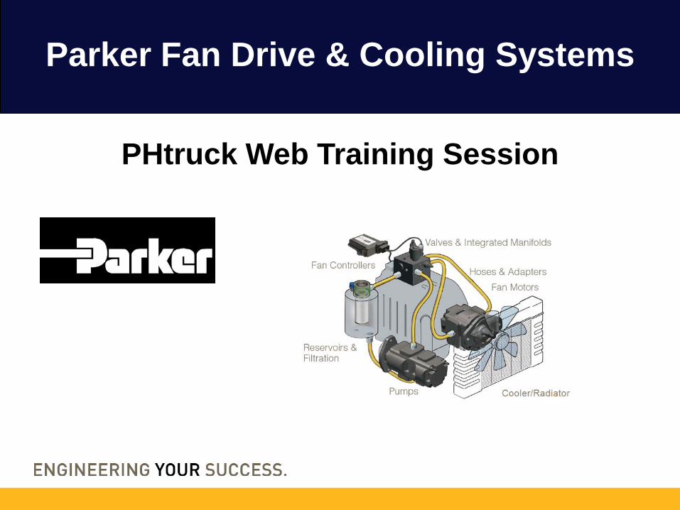
Parker Fan Drive & Cooling Systems
PHtruck Web Training Session
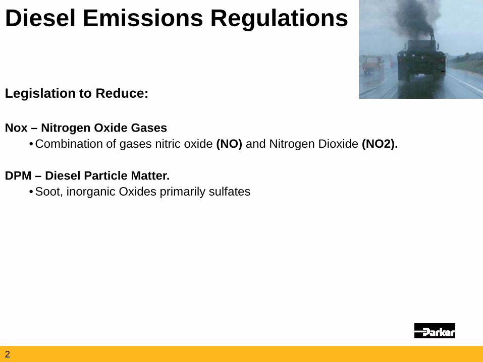
Legislation to Reduce: Nox – Nitrogen Oxide Gases
• Combination of gases nitric oxide (NO) and Nitrogen Dioxide (NO2).
DPM – Diesel Particle Matter. • Soot, inorganic Oxides primarily sulfates
Diesel Emissions Regulations
2
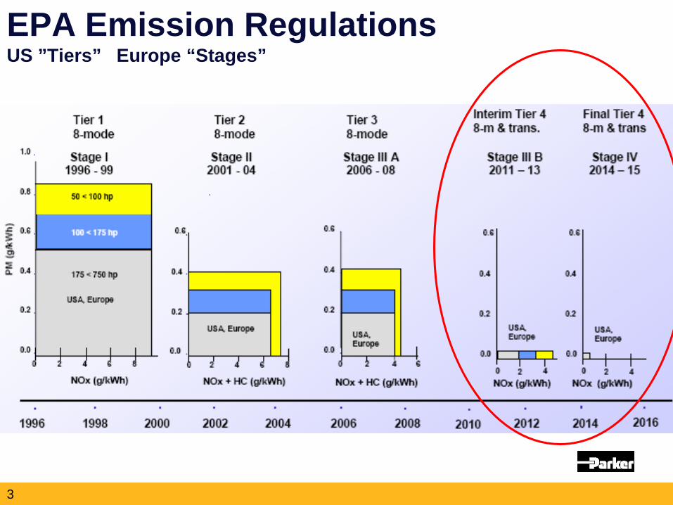
EPA Emission Regulations US ”Tiers” Europe “Stages”
3
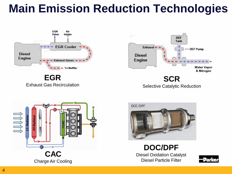
Main Emission Reduction Technologies
SCR Selective Catalytic Reduction
EGR Exhaust Gas Recirculation
CAC Charge Air Cooling
DOC/DPF Diesel Oxidation Catalyst
Diesel Particle Filter
4
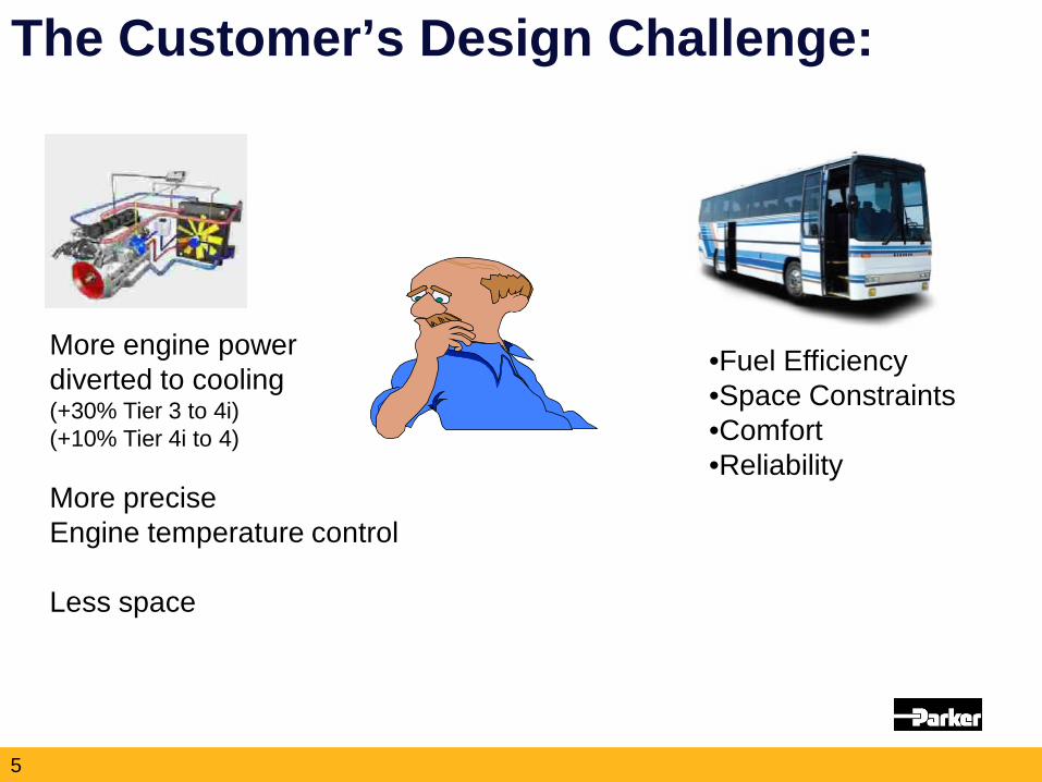
The Customer’s Design Challenge:
More engine power diverted to cooling (+30% Tier 3 to 4i) (+10% Tier 4i to 4) More precise Engine temperature control Less space
•Fuel Efficiency •Space Constraints •Comfort •Reliability
5

Global Fan Drive Market
North America – Fan Drive + Cooler
6
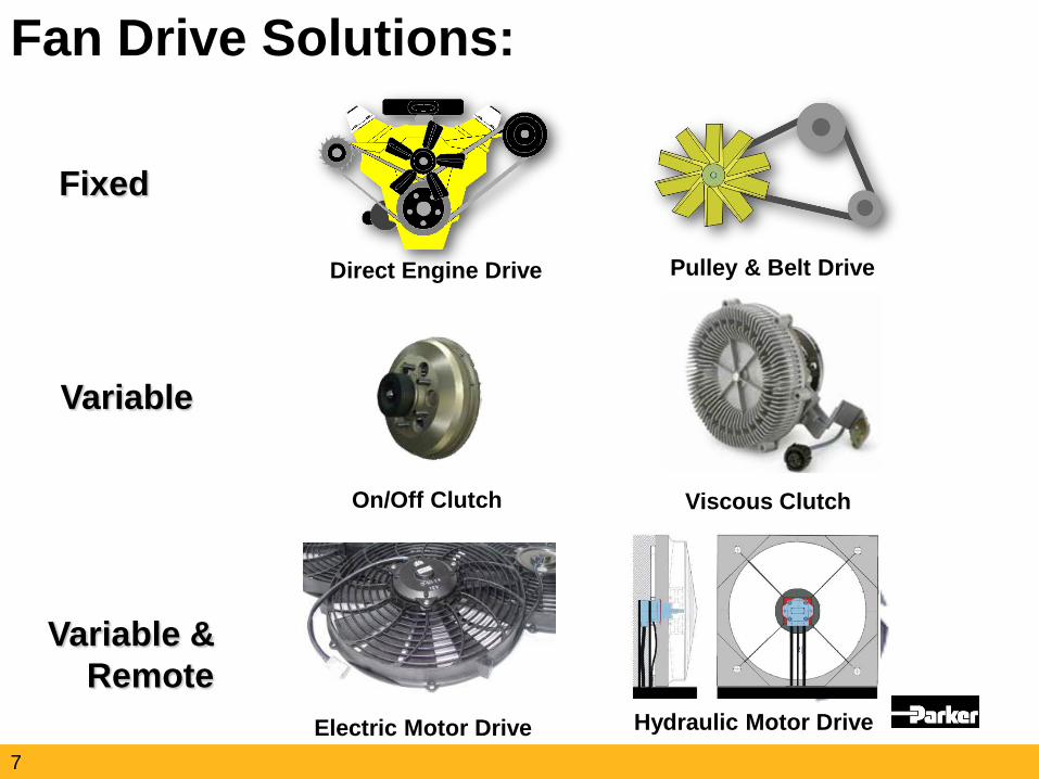
Fan Drive Solutions:
Fixed
Direct Engine Drive Pulley & Belt Drive
Variable & Remote
Electric Motor Drive Hydraulic Motor Drive
Variable
On/Off Clutch Viscous Clutch
7
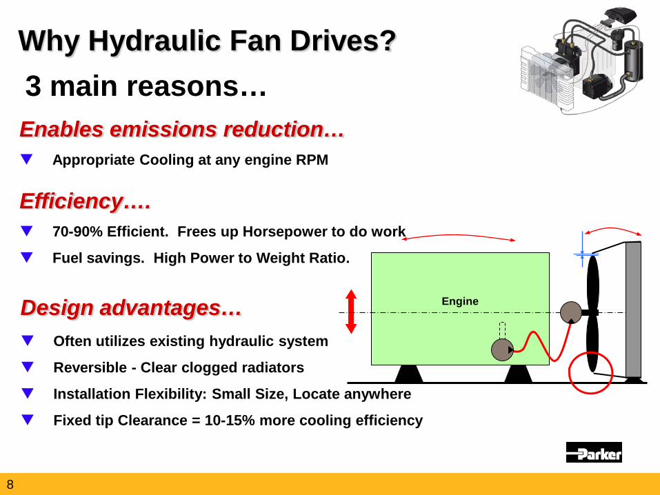
Enables emissions reduction… Appropriate Cooling at any engine RPM
Why Hydraulic Fan Drives? 3 main reasons…
Efficiency…. 70-90% Efficient. Frees up Horsepower to do work
Fuel savings. High Power to Weight Ratio.
Design advantages… Often utilizes existing hydraulic system
Reversible - Clear clogged radiators
Installation Flexibility: Small Size, Locate anywhere
Fixed tip Clearance = 10-15% more cooling efficiency
Engine
8
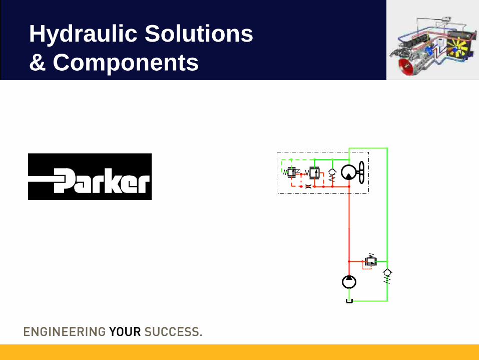
Hydraulic Solutions & Components
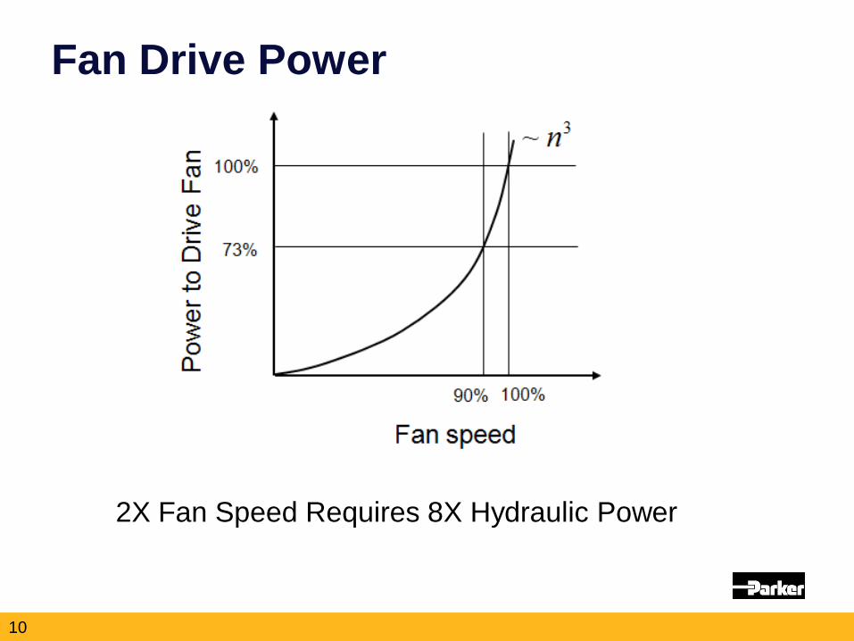
Fan Drive Power
2X Fan Speed Requires 8X Hydraulic Power
10
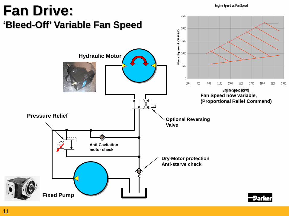
Hydraulic Motor
Pressure Relief Optional Reversing Valve
Fixed Pump
Anti-Cavitation motor check
Dry-Motor protection Anti-starve check
Fan Drive: ‘Bleed-Off’ Variable Fan Speed
Engine Speed vs Fan Speed
0
500
1000
1500
2000
2500
500 700 900 1100 1300 1500 1700 1900 2100 2300
Engine Speed (RPM)
Fa
n S
pe
ed
(R
PM
)
Fan Speed now variable, (Proportional Relief Command)
11
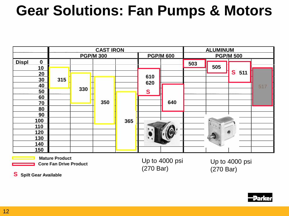
CAST IRON ALUMINUM PGP/M 300 PGP/M 600 PGP/M 500
Displ 10
20 30 40 50 60 70 80 90
100 110 120 130 140 150
315
330
350
365
610 620
640
503 505 511
517 S
S
Mature Product Core Fan Drive Product
S Spilt Gear Available
Gear Solutions: Fan Pumps & Motors
0
Up to 4000 psi (270 Bar)
Up to 4000 psi (270 Bar)
12
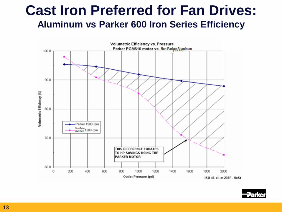
Cast Iron Preferred for Fan Drives: Aluminum vs Parker 600 Iron Series Efficiency
13
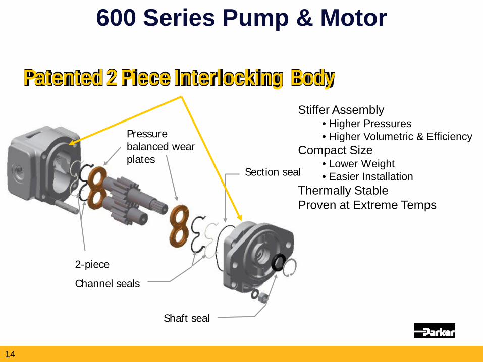
2-piece
Channel seals
Shaft seal
Pressure balanced wear plates
Section seal
600 Series Pump & Motor
Patented 2 Piece Interlocking Body Stiffer Assembly
• Higher Pressures • Higher Volumetric & Efficiency
Compact Size • Lower Weight • Easier Installation
Thermally Stable Proven at Extreme Temps
14
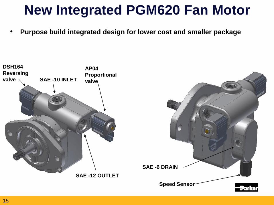
New Integrated PGM620 Fan Motor
SAE -12 OUTLET
AP04 Proportional valve
Speed Sensor
SAE -6 DRAIN
SAE -10 INLET
DSH164 Reversing valve
• Purpose build integrated design for lower cost and smaller package
15
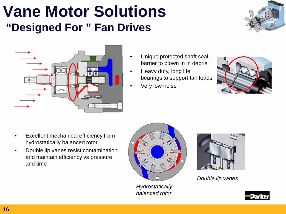
Vane Motor Solutions “Designed For ” Fan Drives
• Unique protected shaft seal, barrier to blown in in debris
• Heavy duty, long life bearings to support fan loads
• Very low noise
• Excellent mechanical efficiency from hydrostatically balanced rotor
• Double lip vanes resist contamination and maintain efficiency vs pressure and time
Hydrostatically balanced rotor
Double lip vanes
16
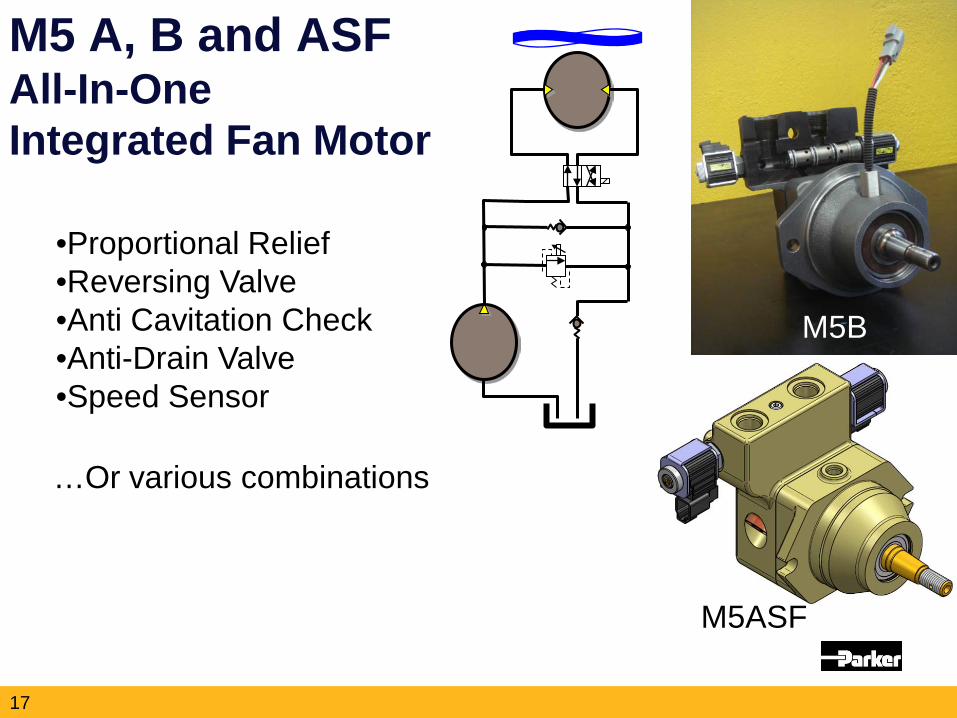
M5 A, B and ASF All-In-One Integrated Fan Motor
•Proportional Relief •Reversing Valve •Anti Cavitation Check •Anti-Drain Valve •Speed Sensor
…Or various combinations
M5B
M5ASF
17
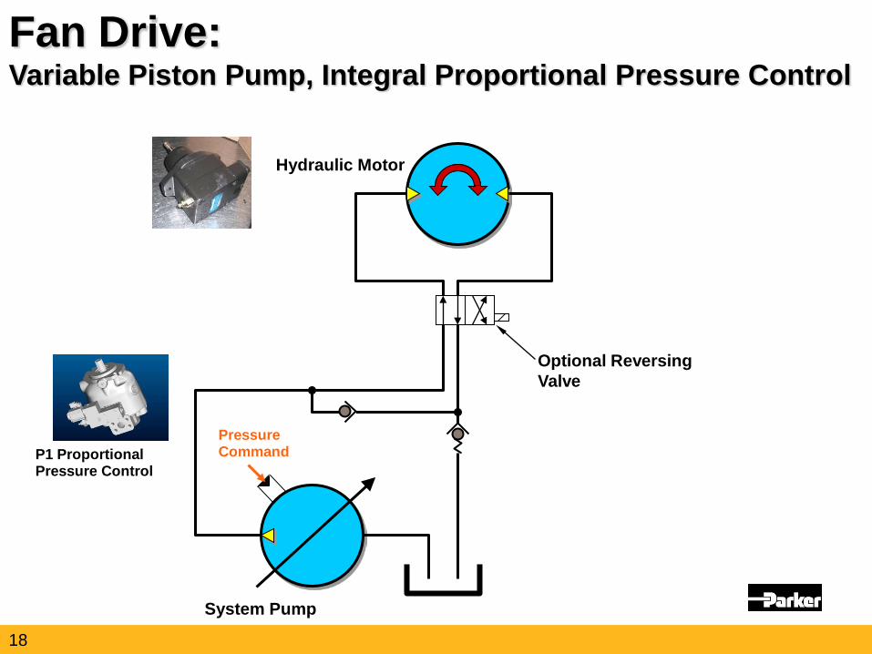
Hydraulic Motor
P1 Proportional Pressure Control
Optional Reversing Valve
System Pump
Fan Drive: Variable Piston Pump, Integral Proportional Pressure Control
Pressure Command
18
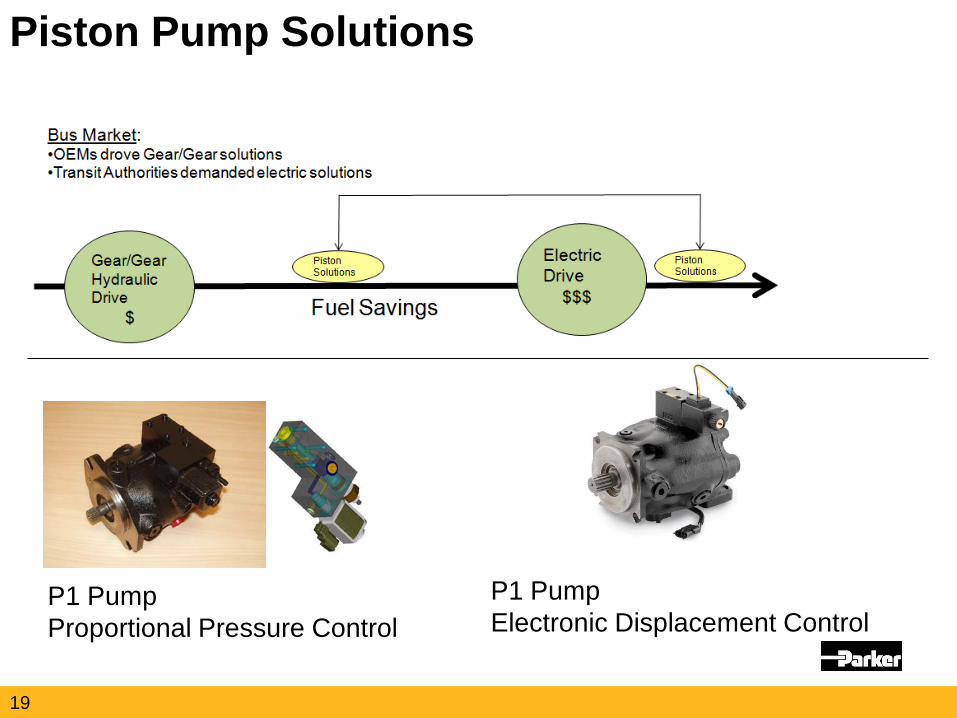
Piston Pump Solutions
P1 Pump Proportional Pressure Control
P1 Pump Electronic Displacement Control
19
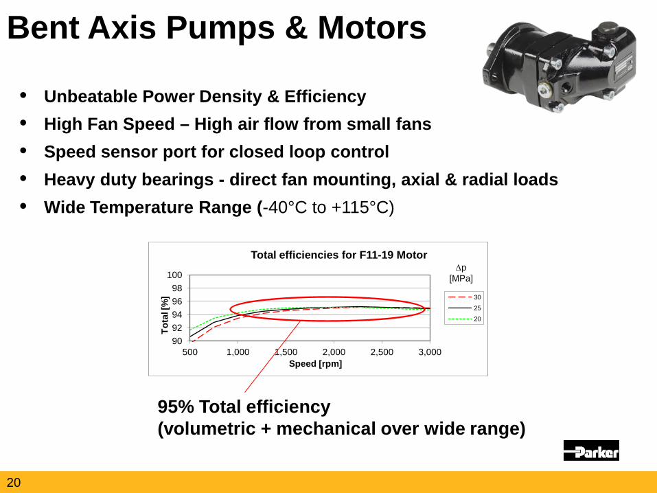
• Unbeatable Power Density & Efficiency • High Fan Speed – High air flow from small fans • Speed sensor port for closed loop control • Heavy duty bearings - direct fan mounting, axial & radial loads • Wide Temperature Range (-40°C to +115°C)
Bent Axis Pumps & Motors
90 92 94 96 98
100
500 1,000 1,500 2,000 2,500 3,000
Tota
l [%
]
Speed [rpm]
Total efficiencies for F11-19 Motor
30
25
20
∆p [MPa]
95% Total efficiency (volumetric + mechanical over wide range)
20
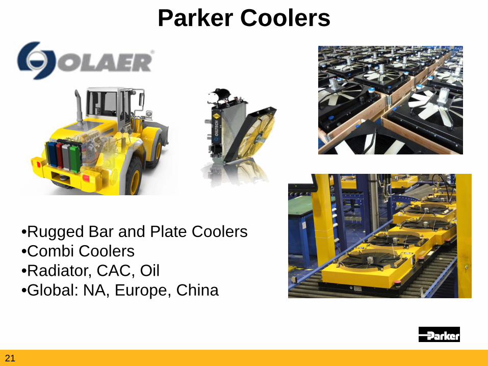
Parker Coolers
•Rugged Bar and Plate Coolers •Combi Coolers •Radiator, CAC, Oil •Global: NA, Europe, China
21
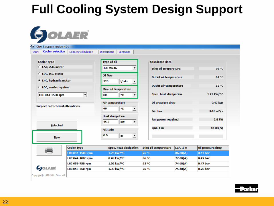
Full Cooling System Design Support
22
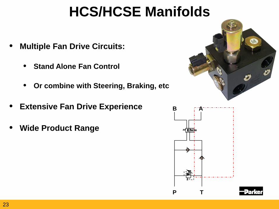
HCS/HCSE Manifolds
• Multiple Fan Drive Circuits:
• Stand Alone Fan Control
• Or combine with Steering, Braking, etc
• Extensive Fan Drive Experience
• Wide Product Range
B A
P T
23
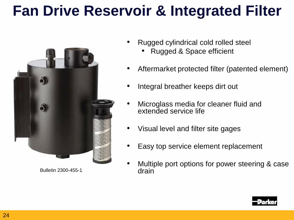
Fan Drive Reservoir & Integrated Filter
• Rugged cylindrical cold rolled steel • Rugged & Space efficient
• Aftermarket protected filter (patented element)
• Integral breather keeps dirt out
• Microglass media for cleaner fluid and extended service life
• Visual level and filter site gages
• Easy top service element replacement
• Multiple port options for power steering & case drain
Bulletin 2300-455-1
24
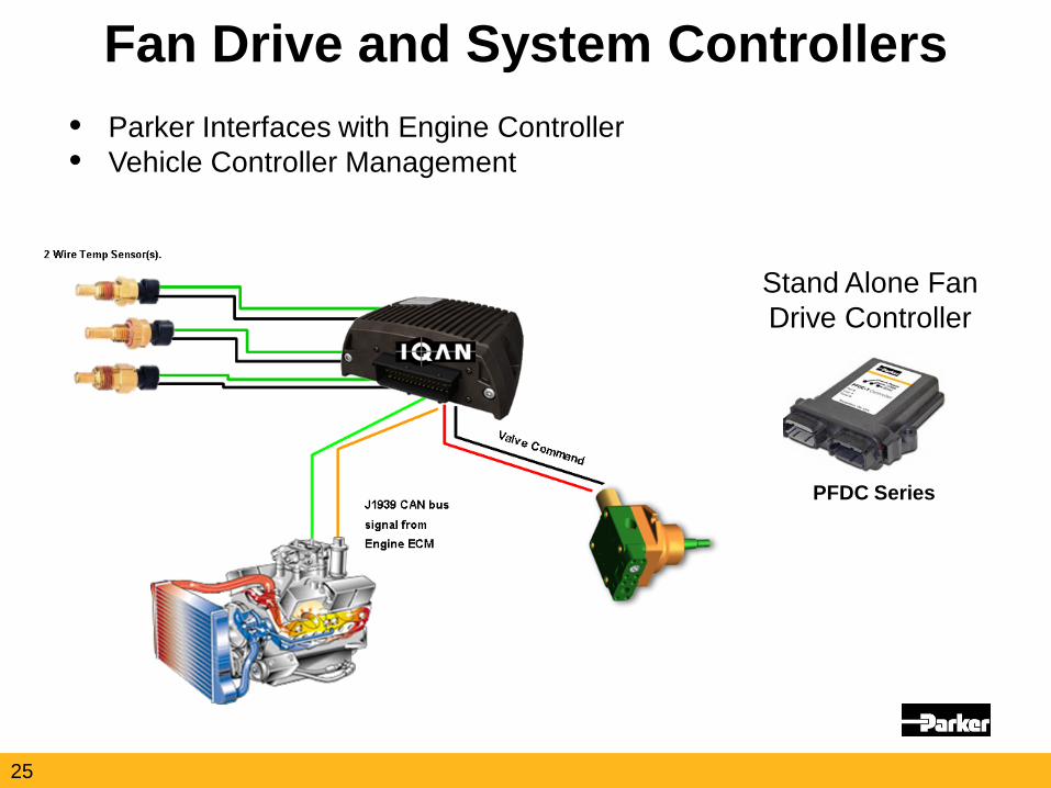
Fan Drive and System Controllers • Parker Interfaces with Engine Controller • Vehicle Controller Management
PFDC Series
Stand Alone Fan Drive Controller
25
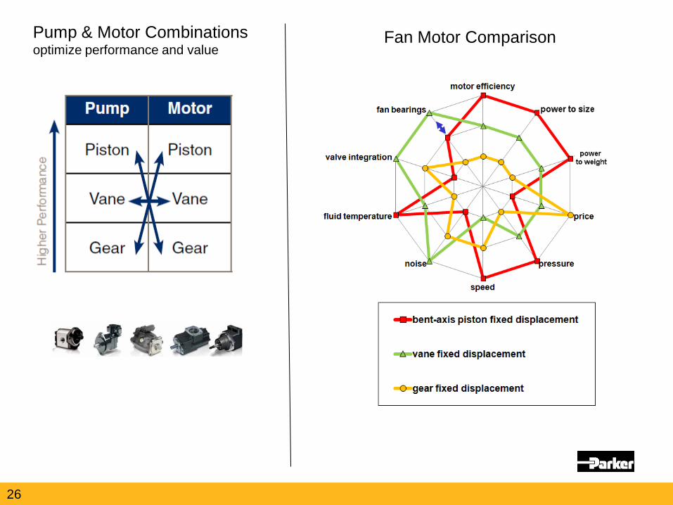
Pump & Motor Combinations optimize performance and value
Fan Motor Comparison
26
27
Electric Fan Drive Solutions
27
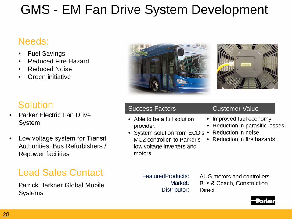
• Fuel Savings • Reduced Fire Hazard • Reduced Noise • Green initiative
• Able to be a full solution provider.
• System solution from ECD’s MC2 controller, to Parker’s low voltage inverters and motors
• Improved fuel economy • Reduction in parasitic losses • Reduction in noise • Reduction in fire hazards
Patrick Berkner Global Mobile Systems
AUG motors and controllers Bus & Coach, Construction Direct
Needs:
Solution
FeaturedProducts: Market:
Distributor:
Lead Sales Contact
Success Factors Customer Value • Parker Electric Fan Drive
System
• Low voltage system for Transit Authorities, Bus Refurbishers / Repower facilities
GMS - EM Fan Drive System Development
28
29
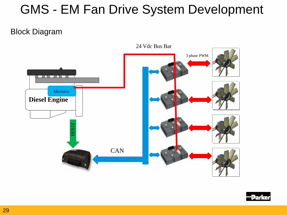
GMS - EM Fan Drive System Development Block Diagram
Diesel Engine
J1939
Alternator
24 Vdc Bus Bar
CAN
3 phase PWM
30
GMS - EM Fan Drive System Development This Fan System is still in Development • Target customer is the Transit Authority, bus refurbisher, repower facility
• NOT OEM’s • TA’s look for Fuel savings, reduction in maintenance, etc.
• Now with Parker Olaer as a solution, Parker can be able to provide a full solution
• Olaer oil coolers • In the short term – they can supply oil coolers to the truck markets.
• Can be used for smaller radiators for hybrid trucks, smaller vehicles.
• If you believe you have a potential opportunity, talk to Pat Berkner to discuss.
30
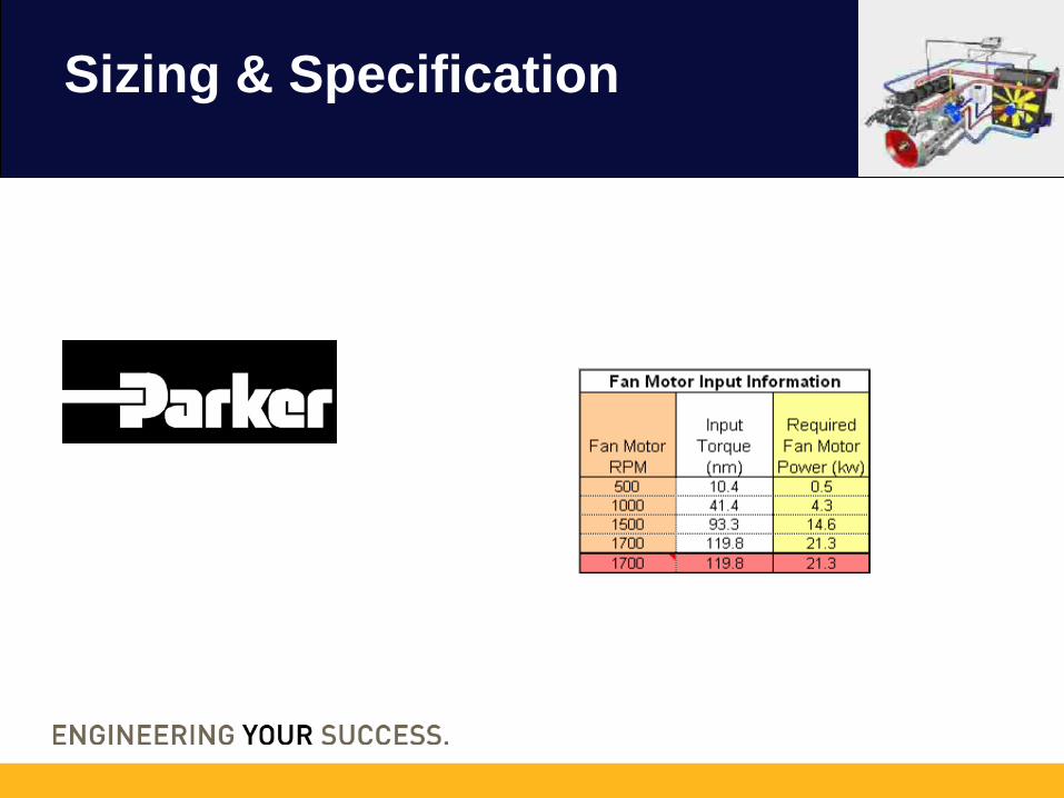
Sizing & Specification
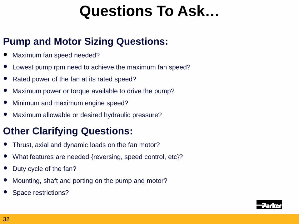
Pump and Motor Sizing Questions: Maximum fan speed needed?
Lowest pump rpm need to achieve the maximum fan speed?
Rated power of the fan at its rated speed?
Maximum power or torque available to drive the pump?
Minimum and maximum engine speed?
Maximum allowable or desired hydraulic pressure?
Other Clarifying Questions: Thrust, axial and dynamic loads on the fan motor?
What features are needed {reversing, speed control, etc}?
Duty cycle of the fan?
Mounting, shaft and porting on the pump and motor?
Space restrictions?
Questions To Ask…
32
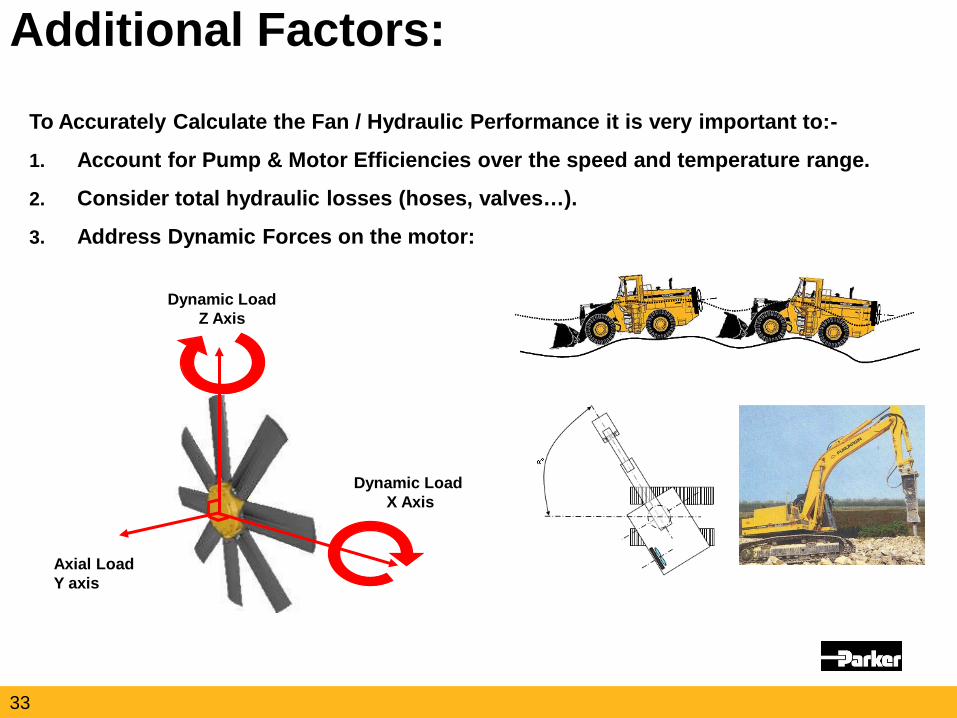
To Accurately Calculate the Fan / Hydraulic Performance it is very important to:-
1. Account for Pump & Motor Efficiencies over the speed and temperature range.
2. Consider total hydraulic losses (hoses, valves…).
3. Address Dynamic Forces on the motor:
Additional Factors:
Dynamic Load X Axis
Dynamic Load Z Axis
Axial Load Y axis
33
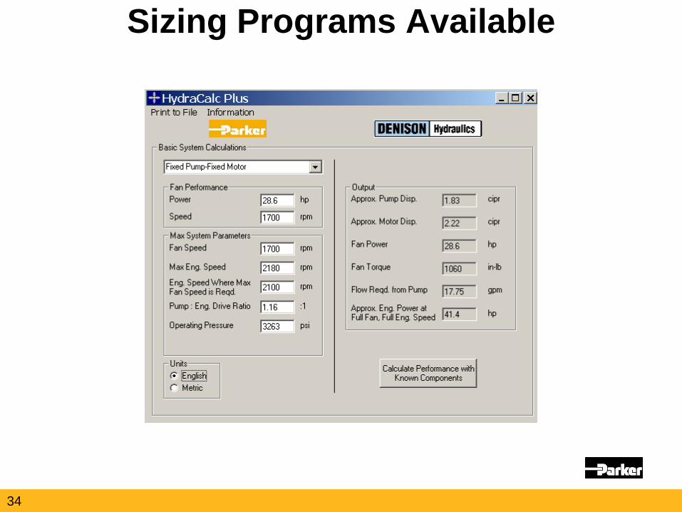
Sizing Programs Available
34
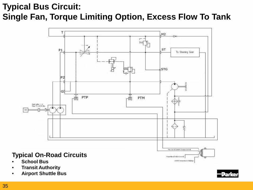
Typical Bus Circuit: Single Fan, Torque Limiting Option, Excess Flow To Tank
Typical On-Road Circuits • School Bus • Transit Authority • Airport Shuttle Bus
35
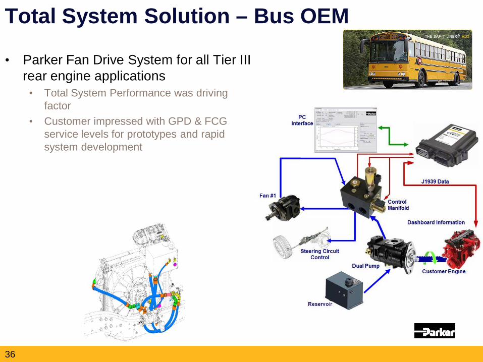
36
Total System Solution – Bus OEM
• Parker Fan Drive System for all Tier III rear engine applications
• Total System Performance was driving factor
• Customer impressed with GPD & FCG service levels for prototypes and rapid system development
37
•Focused Team (TBB unfamiliar with hydraulics) •600 Performance •System Approach •Won with Performance, Maintained with Support
•High Temps: Controller, Pump/Motor •System Cleanliness •Validate to Entire Cooling Duty Cycle •Bus Market: No BS, Field Support
Keys to the Win
Lessons Learned
Sales Strategy & Support
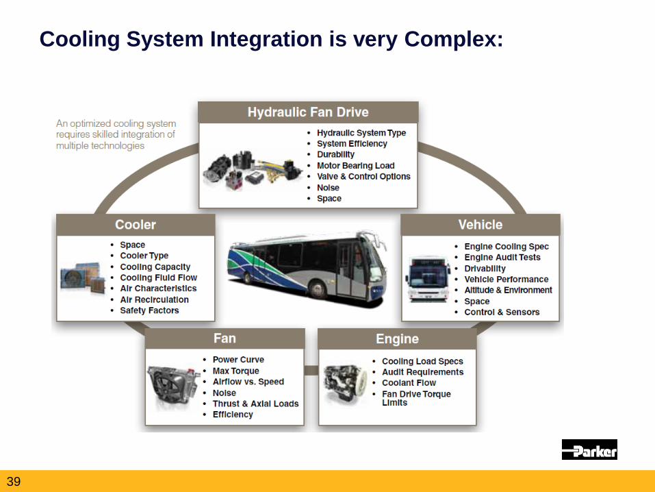
Cooling System Integration is very Complex:
39
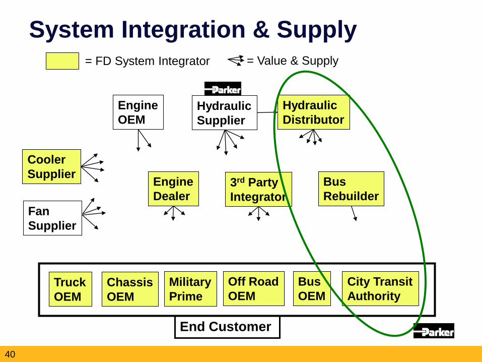
= FD System Integrator = Value & Supply
System Integration & Supply
Truck OEM
Chassis OEM
Bus OEM
Off Road OEM
City Transit Authority
Military Prime
Engine OEM
Hydraulic Supplier
Bus Rebuilder
3rd Party Integrator
Engine Dealer
Hydraulic Distributor
Cooler Supplier
Fan Supplier
End Customer
40
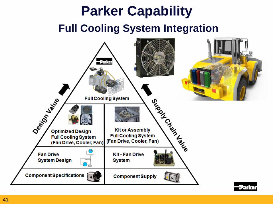
Parker Capability Full Cooling System Integration
41
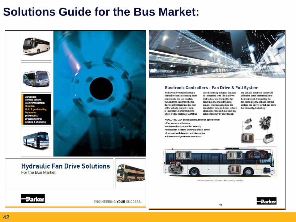
Solutions Guide for the Bus Market:
42