Embed Size (px)
Citation preview
Parking Lot Creation using Corridors
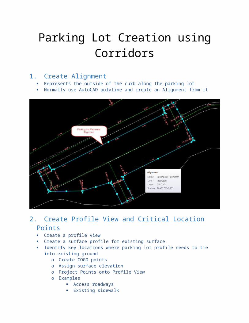
1. Create Alignment Represents the outside of the curb along the parking lot Normally use AutoCAD polyline and create an Alignment from it
2. Create Profile View and Critical Location Points Create a profile view Create a surface profile for existing surface Identify key locations where parking lot profile needs to tie into existing ground
o Create COGO points o Assign surface elevationo Project Points onto Profile Viewo Examples
Access roadways Existing sidewalk Other features
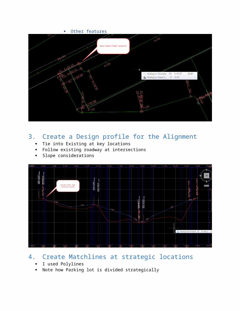
3. Create a Design profile for the Alignment Tie into Existing at key locations Follow existing roadway at intersections Slope considerations
4. Create Matchlines at strategic locations I used Polylines Note how Parking lot is divided strategically
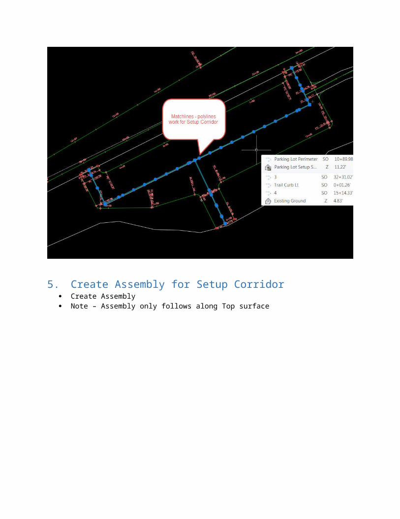
5. Create Assembly for Setup Corridor Create Assembly Note – Assembly only follows along Top surface
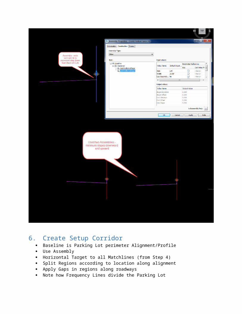
6. Create Setup Corridor Baseline is Parking Lot perimeter Alignment/Profile Use Assembly Horizontal Target to all Matchlines (from Step 4) Split Regions according to location along alignment Apply Gaps in regions along roadways Note how Frequency Lines divide the Parking Lot
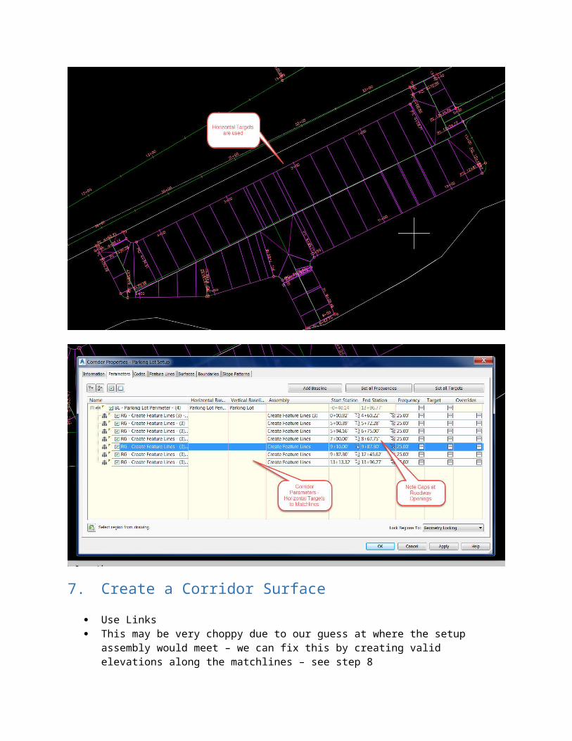
7. Create a Corridor Surface Use Links This may be very choppy due to our guess at where the setup assembly would meet – we can fix
this by creating valid elevations along the matchlines – see step 8 Note: this is to give an idea on how to do – with a more attention to detail on the setup
corridor(s), one can create surfaces that represent minimum and maximum slopes. Going
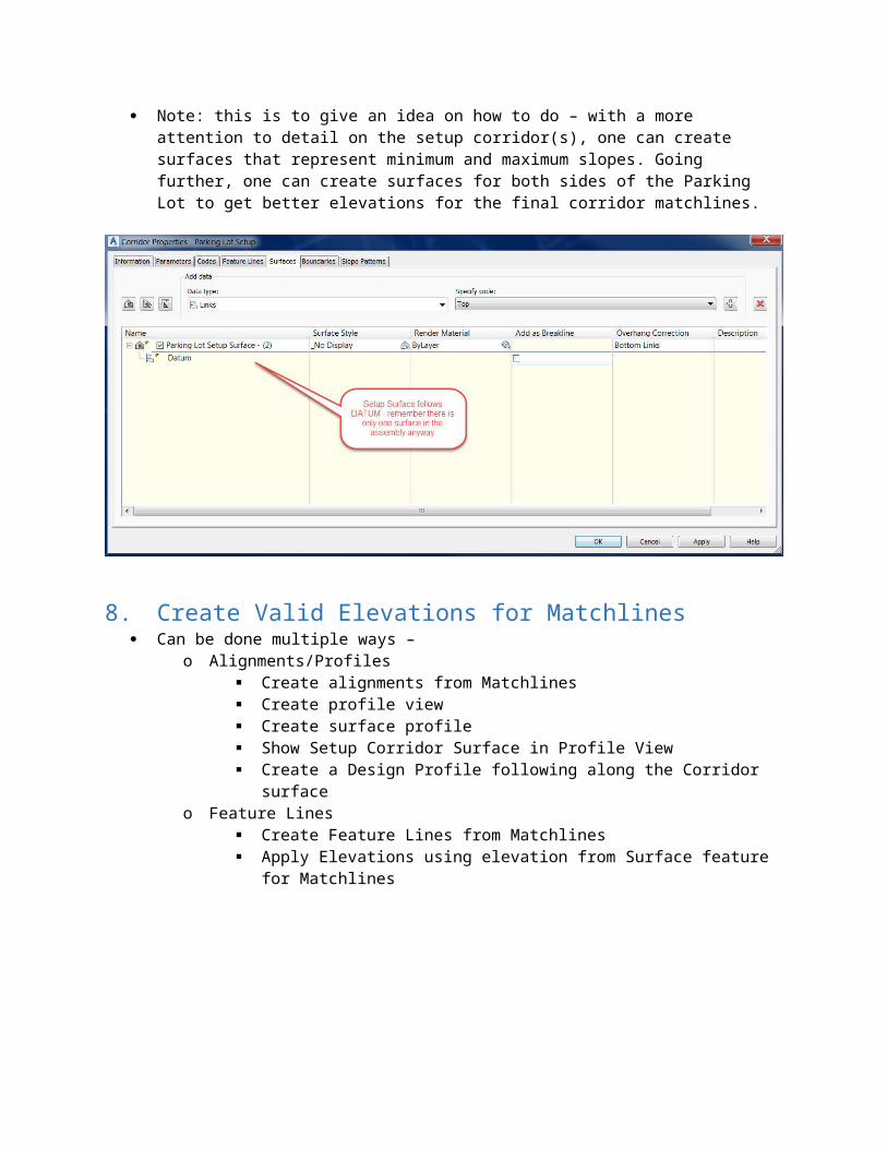
further, one can create surfaces for both sides of the Parking Lot to get better elevations for the final corridor matchlines.
8. Create Valid Elevations for Matchlines Can be done multiple ways –
o Alignments/Profiles Create alignments from Matchlines Create profile view Create surface profile Show Setup Corridor Surface in Profile View Create a Design Profile following along the Corridor surface
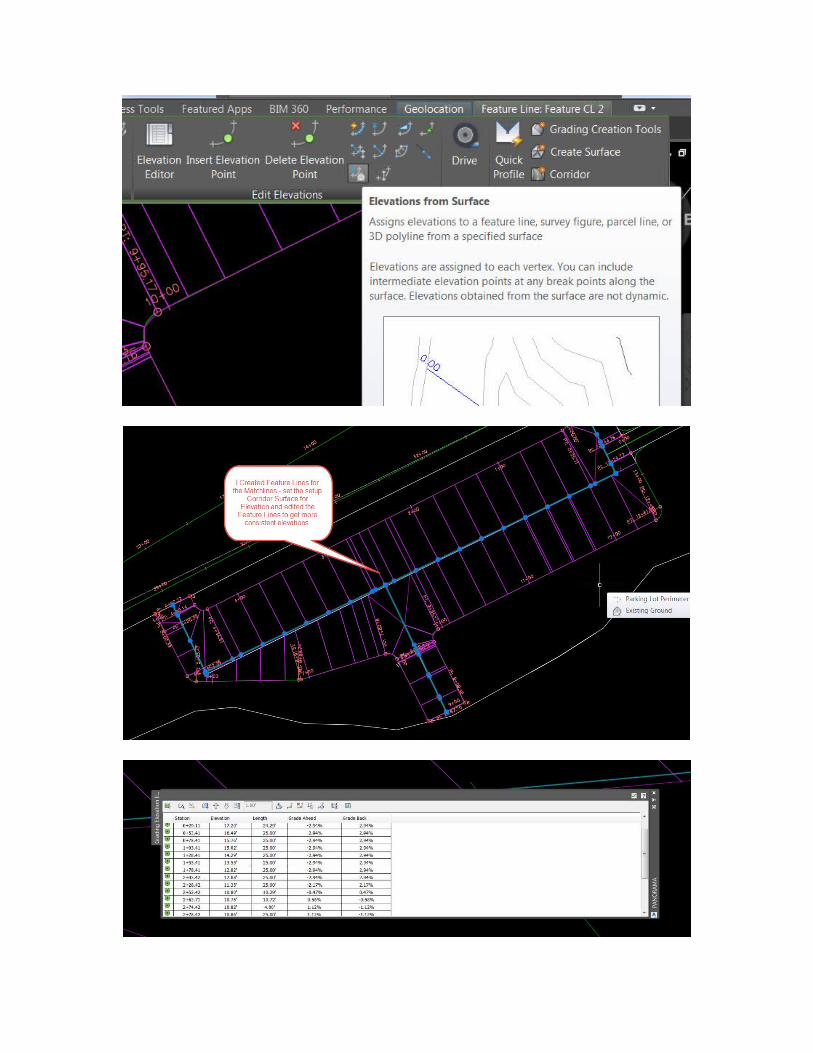
o Feature Lines Create Feature Lines from Matchlines Apply Elevations using elevation from Surface feature for Matchlines
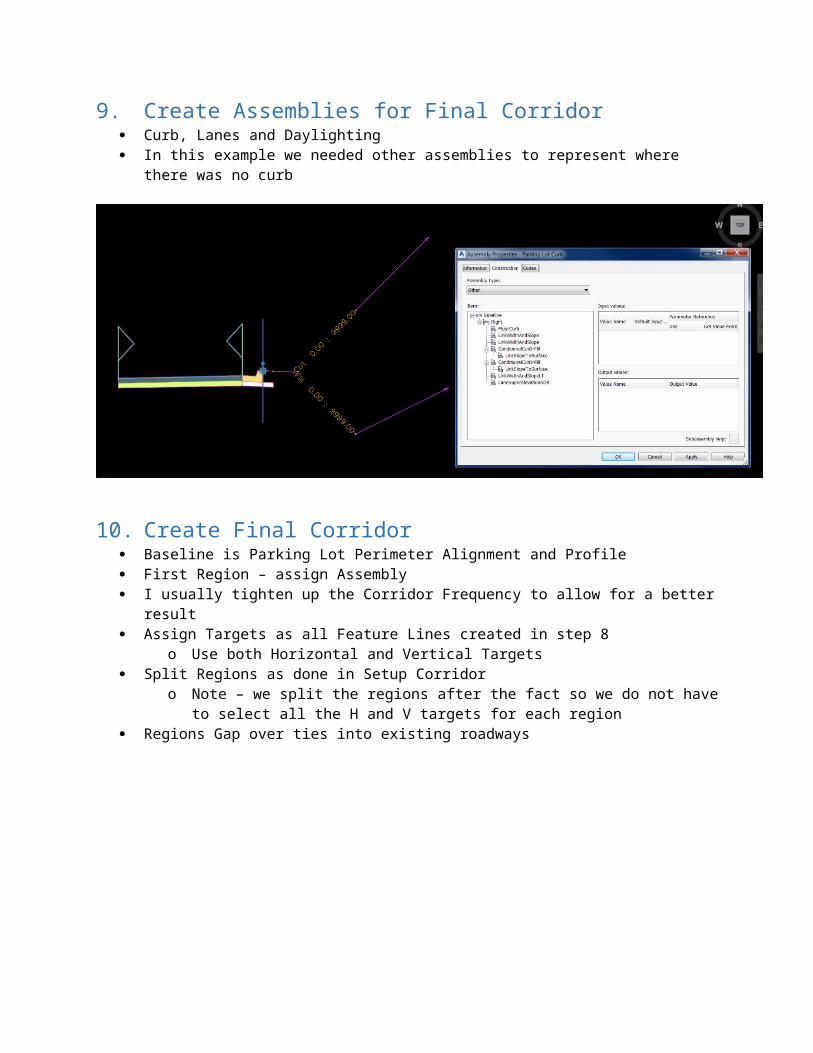
9. Create Assemblies for Final Corridor Curb, Lanes and Daylighting In this example we needed other assemblies to represent where there was no curb
10. Create Final Corridor Baseline is Parking Lot Perimeter Alignment and Profile First Region – assign Assembly I usually tighten up the Corridor Frequency to allow for a better result Assign Targets as all Feature Lines created in step 8
o Use both Horizontal and Vertical Targets Split Regions as done in Setup Corridor
o Note – we split the regions after the fact so we do not have to select all the H and V targets for each region
Regions Gap over ties into existing roadways
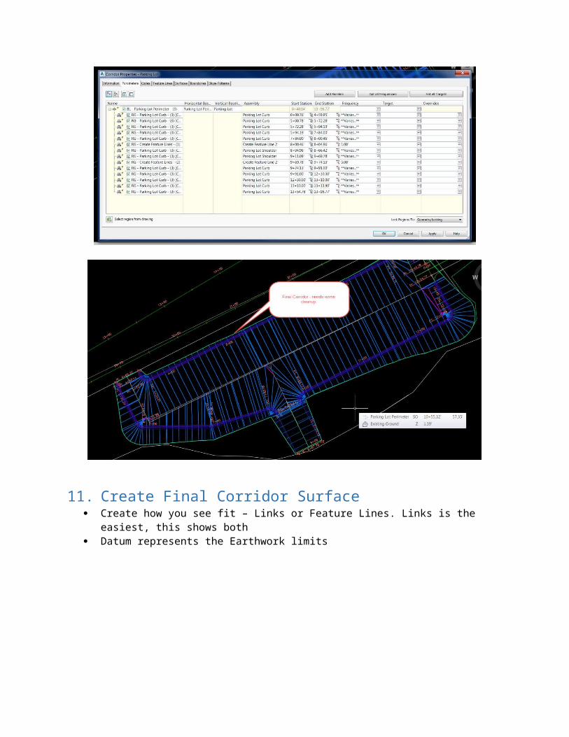
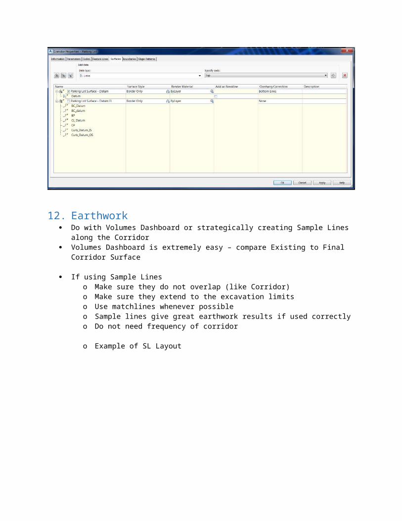
11. Create Final Corridor Surface Create how you see fit – Links or Feature Lines. Links is the easiest, this shows both Datum represents the Earthwork limits
12. Earthwork Do with Volumes Dashboard or strategically creating Sample Lines along the Corridor Volumes Dashboard is extremely easy – compare Existing to Final Corridor Surface
If using Sample Lineso Make sure they do not overlap (like Corridor)
o Make sure they extend to the excavation limitso Use matchlines whenever possibleo Sample lines give great earthwork results if used correctlyo Do not need frequency of corridor
o Example of SL Layout