Embed Size (px)
Citation preview

Pars Oil & Gas Company
Welding, Burning & Cutting Safety Procedure
HEALTH, SAFETY AND ENVIRONMENT PROCEDURE
Welding, Burning & Cutting Safety Procedure
DOCUMENT ID - PR-70-POGC-001 REVISION ‐ 0.0

Pars Oil & Gas Company
Welding, Burning & Cutting Safety Procedure
Pages
43
Revision 00
Document ID.
PR-70-POGC-001
HSE Department
Welding, Burning & Cutting Safety Procedure
Document Authorization
Document Type
Security Classification
Document
Authority/Owner
Document Custodian
Safety Procedure Unrestricted P.O.G.C HSE
Document Author Approved By
HSE-S564392 M.Ansari
HSE-S593443

PARS OIL & GAS COMPANY
September 2012- Welding, Burning and Cutting Safety Procedure Page 2
Table of Contents
1. INTRODUCTION ..................................................................................................................... 3
2. PURPOSE .................................................................................................................................. 3
3. SCOPE........................................................................................................................................ 3
4. RESPONSIBILITIES ............................................................................................................... 3
5. PROCEDURE............................................................................................................................ 4
5.1 GENERAL REQUIREMENT ....................................................................................................... 4
5.2 INERT-GAS METAL-ARC WELDING ........................................................................................ 11
5.3 WELDING, CUTTING, OR HEATING OF METALS OF TOXIC SIGNIFICANCE................................. 12
5.4 GAS WELDING AND BURNING .............................................................................................. 12
5.5 ELECTRIC ARC WELDING AND BURNING ............................................................................. 31
5.6 RESISTANCE WELDING ......................................................................................................... 37
6. DEFFINITION ........................................................................................................................ 40
7. REFERENCES ........................................................................................................................ 40
8. APPENDIX ............................................................................................................................. 40
SUGGESTION FORM

PARS OIL & GAS COMPANY
September 2012- Welding, Burning and Cutting Safety Procedure Page 3
1. INTRODUCTION
Pars Oil and Gas Company (POGC), a subsidiary of National Iranian Oil Company
(NIOC), was established in 1998. POGC is a developmental and manufacturing
organization that specializes in the fields of engineering and management of development
projects, production, operation and integrated management of oil and gas reservoirs.
POGC’s mission is to ensure sustainable and preservative production and development of
Iran’s oil and gas industry in the areas under its responsibility, development of oil and gas
value chain as well as optimization of energy supply processes at national, regional and
international levels. POGC is also in charge of development of joint and non-joint oil and
gas fields of the country including South Pars, North Pars, Golshan and Ferdowsi.
Aimed at creating superior value and boosting the level of satisfaction of the beneficiaries
and with an approach focusing on sustainable, integrated and knowledge-oriented
production and development, the company feels committed to comply with national and
international requirements, regulations and standards in such areas as quality, safety, as
well as occupational and environmental health.
2. PURPOSE
The purpose of this procedure is to ensure a safe and controlled working environment and
the protection of personnel, plant and equipment in the vicinity of welding and burning
operations.
3. SCOPE
This procedure is applicable for each location in all POGC south pars gas field
development phases projects/ worksite locations where there is risk of welding, cutting and
burning harm due to the work nature.
4. RESPONSIBILITIES
4.1 Site Manager
The Site Manager is responsible for assessing the need and granting permission for
hot work to be carried out on "live" lines and or in the vicinity of flammable liquids
and Hazardous areas .
4.2 Safety Authority
The Safety Authority is responsible for monitoring the safety of all welding
practices.
4.3 Task Supervisors
The Task Supervisor is responsible for :
• Ensuring that the requirements of the Work Permit are carried out.
• Familiarizing himself and his operators with the details of the procedures.
• Ensuring that due care and attention is maintained throughout the operation.
4.4 Personnel Raising Requisition or Contract

PARS OIL & GAS COMPANY
September 2012- Welding, Burning and Cutting Safety Procedure Page 4
It is the responsibility of any person raising a requisition or contract for any welding
equipment or contracted work requesting welding equipment to be used to ensure
that the equipment is in accordance with the requirement of the present standard,
particularly as far as the worker protection against electrical shocks is concerned.
4.5 Operations Assistant
The Operations Assistant or his delegate is responsible for assessing the need and
granting permission for any hot work to be carried out in hazardous areas.
4.6 Head of Field Operations / Field Supervisors (Process/shift Superintendent )
Head of Field Operations / Field Supervisor is responsible for ensuring that:
- A Hot Work Permit is raised and issued prior to the commencement of work.
- All appropriate precautions detailed in this procedure are entered on the Hot
Work Permit and are implemented prior to commencement of the task.
4.7 Permit Controller
The Permit Controller is responsible for:
- Ensuring that the requirements of the Work Permit are carried out.
- Familiarizing him and the Multi Skilled technicians with the details of the
procedures.
- Ensuring that due care and attention is maintained throughout the operation.
- Liaison with Field Supervision and safety officer to ensure adequate
planning and coordination
5. PROCEDURE
5.1 General Requirement Applicable To Any Welding, Burning or Cutting
Operations
5.1.1 Fume Hazards
A welder in a confined space must be accompanied by a person who stays outside and can
give the operator any assistance as required.
In general an upper exposure limit for welding fumes is 5mg/m3.
However for certain elements e.g. Cadmium, which may be present in welding fumes lower
limits are set and specialist advice should be sought.
Examples of methods of controlling welding fumes are given in Table 1.
Toxic gases and fumes, produced in welding operations, create serious hazards:
• Fumes can be produced from the welding of materials that are greasy. All such
materials must be thoroughly de-greased and dried before welding.
• Harmful lead fumes are produced when welding or cutting material coated with lead
based paint.
• The inhalation of fumes from the welding or cutting of zinc galvanized metal, may
result in "Metal Fume Fever", which is characterized by a raised temperature, aching
muscles, shivering and sweating. The symptoms develop in a few hours after exposure
to the fumes and persist for approximately 24 hours.
• Air-line masks, or high efficiency respirators should be worn in those cases where
galvanized, painted, lead or cadmium coated materials are being cut or welded.

PARS OIL & GAS COMPANY
September 2012- Welding, Burning and Cutting Safety Procedure Page 5
• Nitrous fumes may be produced on occasions where an oxy-propane fumes flame
impinges on a large mass of metal for long periods. A deficiency of air during such
work may also produce carbon monoxide.
• The arc welding of iron, or steel, is accompanied by the evolution of considerable
quantities of fumes consisting of very fine particles of iron oxide.
• The welding of brass, bronze and manganese steel generates large quantities of Carbon
Monoxide and Carbon Dioxide gases which require the provision of adequate
ventilation or the wearing of suitable apparatus to give effective nasal/oral protection.
For the purpose of welding fume extraction, a ventilation system could be considered as
adequate if providing a minimum of 100 air changes per hour of the considered enclosed
space volume.
Where hardened deposits are found on the equipment, welding or cutting must not be
started until the general nature of the deposits are established.
TABLE 1 - METHODS OF CONTROLLING WELDING FUMES
Welding process
Environment
Hazardous
components
Recommended minimum
control
Manual metal arc
(stick) - mild steel
Open Air
Welding shelter
Workshop
Enclosed environment
Confined space
Fe, Fluoride
Fe, Fluoride
Fe, Fluoride
Fe, Fluoride
Fe, Fluoride
---
LEV
LEV
LEV + FFP
LEV + RPE or FFP
Manual metal arc -
stainless steel
Open Air
Welding shelter
Workshop
Enclosed environment
Confined space
Cr, Ni
Cr, Ni
Cr, Ni
Cr, Ni
Cr, Ni
LEV
LEV
LEV
LEV + FFP
LEV + RPE full face
Tungsten Inert
Gas (TIG)
Open Air
Welding shelter
Workshop
Enclosed environment
Confined space
---
---
---
---
Weld gases
---
---
---
FFP
Air-line + LEV
LEV = local exhaust ventilation / fan
RPE = respiratory protective equipment
FFP = filtering face piece respirator
Air-line = compressed air-line breathing apparatus.
5.1.2 Fire, Explosion and electrocution hazards
PARS OIL & GAS COMPANY
September 2012- Welding, Burning and Cutting Safety Procedure Page 6
No welding or cutting within a "live" gas plant or at the vicinity of flammable liquids may
be done without a Work Permit (MA-64-POGC-001) and the conditions laid down on that
permit must be strictly observed.
In all welding & cutting operations, a portable fire extinguisher must be readily accessible
near the work.
An extinguisher designated for fire watch must be used (8 kg dry powder minimum). Do
not use extinguishers which are permanently positioned for emergency use only.
Fire Fighting & Safety Department approval must be obtained before welding or burning on
pipelines where mechanical seal plugs are installed.
The work must be suitably screened to prevent sparks and hot metal from flying outside the
immediate work area.
Fire blankets are to be used to screen local or other areas and equipment. The use of
flammable substances as screen is forbidden (plastics sheets).
Welding booths and screens must:
• Be non-combustible.
• Have interior surface which minimize the reflection of dangerous radiation.
• Allow thorough ventilation.
THE WORK PIECE MUST BE BONDED TO EARTH BEFORE STARTING ANY
WELDING OPERATION.
The earth cables should be fixed at the work site, or if it is not practical, within 3m of the
work site.
Welders must never coil hoses or cables around their body when burning or welding.
Merely closing the valves on the welding torch is NOT A DISCONNECTION, gas cylinder
valves should also be closed and hoses disconnected at cylinders head.
Cutting into any cladding covering polyurethane foam insulation must be undertaken using
a cold cutting method.
If hot cutting is unavoidable then the Safety Superintendent / Authority consulted prior to
commencement of operations so that additional precautions (i.e. Breathing Apparatus or
Air-line Equipment) are entered on the Work Permit.
5.1.3 Pre-Operation Checks
Check if a Main Work Permit (refer to doc No. MA-64-POGC-001) is required and if yes
has been raised.
Check that all tanks, vessels and equipment on which welding, cutting, burning, brazing or
soldering work is to be carried out, are free from flammable gases and vapors, oil and
sludge.
If welding is on one side of a vessel,etc. check thatthere are no flammable gases (or
mixtures) on the other side.
Do not under any circumstances use compressed oxygen for ventilation, or to blow through
propane hoses. Explosions can occur.
Inspect the space between double plates, or weir plates, where flammable material may be
found before welding or burning operations begin.
Before cutting the bottom plates of any tank, drill test holes and take gas tests to ensure that
conditions are safe under the tank floor.

PARS OIL & GAS COMPANY
September 2012- Welding, Burning and Cutting Safety Procedure Page 7
A suitable type of portable extinguisher(s) must be available near the work area.
5.1.4 Work Site
• Ensure that welding and burning equipment is properly maintained and well located
with proper lighting.
• Check that the work piece is properly earthed.
• Check that ventilation is adequate.
• Keep the work area tidy throughout the operation.
• Do not use old barrels, or drums to support work - they may explode and are unstable.
• Only use the approved flint guns supplied for the purpose to ignite oxy-propane or oxy-
acetylene flames.
5.1.5 Ventilation
When the outside of vessels and tanks are being welded or burned, there is a danger of
toxic or flammable gases collecting inside. The heat from outside a tank can ignite an
explosive mixture inside the tank.
Particular care must be taken to ensure adequate ventilation and/or respirator protection.
This is especially relevant in confined spaces, or where toxic or noxious vapors may result
from cutting or burning pipe, etc., which may have special coatings.
Mechanical ventilation:
For purposes of this section, mechanical ventilation shall meet the following requirements:
Mechanical ventilation shall consist of either general mechanical ventilation systems or
local exhaust systems:
General mechanical ventilation shall be of sufficient capacity and so arranged as to produce
the number of air changes necessary to maintain welding fumes and smoke within safe
limits, as defined in Subpart "5.1.8 Inert-gas metal-arc welding" of this part.
Local exhaust ventilation shall consist of freely movable hoods intended to be placed by the
welder or burner as close as practicable to the work. This system shall be of sufficient
capacity and so arranged as to remove fumes and smoke at the source and keep the
concentration of them in the breathing zone within safe limits as defined in Subpart "5.1.8
Inert-gas metal-arc welding" of this part.
Contaminated air exhausted from a working space shall be discharged into the open air or
otherwise clear of the source of intake air.
All air replacing that withdrawn shall be clean and respire-able.
Oxygen shall not be used for ventilation purposes, comfort cooling, blowing dust from
clothing, or for cleaning the work area.
5.1.6 Personnel Protective Equipment
PPE for Welding Operations (For details refer to Doc. No. PR-75-POGC-001)
5.1.6.1 Eye and Face Protection
Employees can be exposed to a large number of hazards that pose danger to their eyes and
face. OSHA requires employers to ensure that employees have appropriate eye or face
protection if they are exposed to eye or face hazards from flying particles, molten metal,
liquid chemicals, acids or caustic liquids, chemical gases or vapors, potentially infected
material or potentially harmful light radiation.

PARS OIL & GAS COMPANY
September 2012- Welding, Burning and Cutting Safety Procedure Page 8
Many occupational eye injuries occur because workers are not wearing any eye protection
while others result from wearing improper or poorly fitting eye protection. Employers must
be sure that their employees wear appropriate eye and face protection and that the selected
form of protection is appropriate to the work being performed and properly fits each worker
exposed to the hazard.
The eye and face protection selected for employee use must clearly identify the
manufacturer. Any new eye and face protective devices must comply with ANSI Z87.1-
1989 or be at least as effective as this standard requires. Any equipment purchased before
this requirement took effect on July 5, 1994, must comply with the earlier ANSI Standard
(ANSI Z87.1-1968) or be shown to be equally effective.
In welding operations, according to primary assessment, one of the following equipment
must be used:
• Safety spectacles. These protective eyeglasses have safety frames constructed of metal
or plastic and impact-resistant lenses. Side shields are available on some models.
• Goggles. These are tight-fitting eye protection that completely cover the eyes, eye
sockets and the facial area immediately surrounding the eyes and provide protection
from impact, dust and splashes. Some goggles will fit over corrective lenses.
• Welding shields. Constructed of vulcanized fiber or fiberglass and fitted with a filtered
lens, welding shields protect eyes from burns caused by infrared or intense radiant light;
they also protect both the eyes and face from flying sparks, metal spatter and slag chips
produced during welding, brazing, soldering and cutting operations. OSHA requires
filter lenses to have a shade number appropriate to protect against the specific hazards
of the work being performed in order to protect against harmful light radiation.
• Face shields. These transparent sheets of plastic extend from the eyebrows to below the chin and across the entire width of the employee's head. Some are polarized for glare protection. Face shields protect against nuisance dusts and potential splashes or sprays of hazardous liquids but will not provide adequate protection against impact hazards. Face shields used in combination with goggles or safety spectacles will provide additional protection against impact hazards.
In welding operations: Ensure that anyone nearby who may be exposed to the radiations and flash from this type of work is also protected. Use gloves or gauntlets made of leather, or some other non-ignitable material, to shield the hands and arms from the radiation of the arc and from sparks. Use sleeves of similar material in addition to gloves if gauntlets are not worn.
The intense light associated with welding operations can cause serious and sometimes permanent eye damage if operators do not wear proper eye protection. The intensity of light or radiant energy produced by welding, cutting or brazing operations varies according to a number of factors including the task producing the light, the electrode size and the arc current. The following table shows the minimum protective shades for a variety of welding, cutting and brazing operations in general industry and in the shipbuilding industry.

PARS OIL & GAS COMPANY
September 2012- Welding, Burning and Cutting Safety Procedure Page 9
Table 2. Filter Lenses for Protection Against Radiant Energy
Operations
Electrode size in 1/32" (0.8mm) Arc
current Minimum* protective
shade Shielded metal arc welding < 3
3 - 5
5 - 8
> 8
< 60
60 - 160
160 - 250
250 - 550
7
8
10
11 Gas metal arc welding
and flux cored
arc welding
< 60
60 - 160
160 - 250
250 - 500
7
10
10
10 Gas tungsten
arc welding < 50
50 - 150
150 - 500
8
8
10 Air carbon (light) < 500 10 Arc cutting (heavy) 500 - 1,000 11 Plasma arc welding < 20
20 - 100
100 - 400
400 - 800
6
8
10
11 Plasma arc cutting (light)**
(medium)**
(heavy)**
< 300
300 - 400
400 - 800
8
9
10 Torch brazing 3 Torch soldering 2 Carbon arc welding 14
Table 3 .Filter Lenses for Protection Against Radiant Energy Operations Plate thickness inches Plate thickness mm Minimum* protective shade
Gas welding:
Light
< 1/8
< 3.2
4
Gas welding:
Medium
1/8 - 1/2
3.2 - 12.7
5
Gas welding:
Heavy
> 1/2
> 12.7
6
Oxygen cutting:
Light
< 1
< 25
3
Oxygen cutting: Medium 1 - 6 25 - 150 4 Oxygen cutting:Heavy > 6 > 150 5 Source: 29 CFR 1910.133(a)(5).
* As a rule of thumb, start with a shade that is too dark to see the weld zone. Then go to a lighter shade which
gives sufficient view of the weld zone without going below the minimum. In oxy fuel gas welding or cutting
where the torch produces a high yellow light, it is desirable to use a filter lens that absorbs the yellow or
sodium line in the visible light of the (spectrum) operation.
** These values apply where the actual arc is clearly seen. Experience has shown that lighter filters may be
used when the arc is hidden by the work piece.
PARS OIL & GAS COMPANY
September 2012- Welding, Burning and Cutting Safety Procedure Page 10
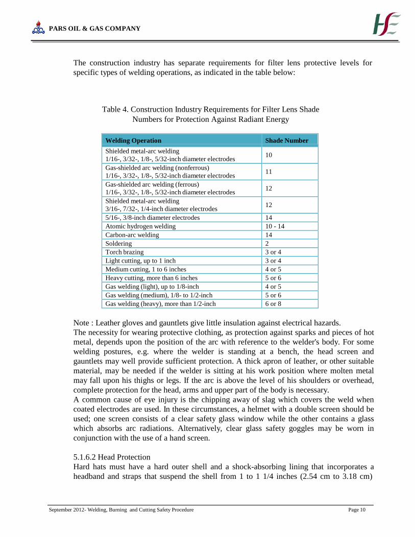
The construction industry has separate requirements for filter lens protective levels for
specific types of welding operations, as indicated in the table below:
Table 4. Construction Industry Requirements for Filter Lens Shade
Numbers for Protection Against Radiant Energy
Welding Operation Shade Number
Shielded metal-arc welding
1/16-, 3/32-, 1/8-, 5/32-inch diameter electrodes
10
Gas-shielded arc welding (nonferrous)
1/16-, 3/32-, 1/8-, 5/32-inch diameter electrodes
11
Gas-shielded arc welding (ferrous)
1/16-, 3/32-, 1/8-, 5/32-inch diameter electrodes
12
Shielded metal-arc welding
3/16-, 7/32-, 1/4-inch diameter electrodes
12
5/16-, 3/8-inch diameter electrodes 14 Atomic hydrogen welding 10 - 14 Carbon-arc welding 14 Soldering 2 Torch brazing 3 or 4 Light cutting, up to 1 inch 3 or 4 Medium cutting, 1 to 6 inches 4 or 5 Heavy cutting, more than 6 inches 5 or 6 Gas welding (light), up to 1/8-inch 4 or 5 Gas welding (medium), 1/8- to 1/2-inch 5 or 6 Gas welding (heavy), more than 1/2-inch 6 or 8
Note : Leather gloves and gauntlets give little insulation against electrical hazards.
The necessity for wearing protective clothing, as protection against sparks and pieces of hot
metal, depends upon the position of the arc with reference to the welder's body. For some
welding postures, e.g. where the welder is standing at a bench, the head screen and
gauntlets may well provide sufficient protection. A thick apron of leather, or other suitable
material, may be needed if the welder is sitting at his work position where molten metal
may fall upon his thighs or legs. If the arc is above the level of his shoulders or overhead,
complete protection for the head, arms and upper part of the body is necessary.
A common cause of eye injury is the chipping away of slag which covers the weld when
coated electrodes are used. In these circumstances, a helmet with a double screen should be
used; one screen consists of a clear safety glass window while the other contains a glass
which absorbs arc radiations. Alternatively, clear glass safety goggles may be worn in
conjunction with the use of a hand screen.
5.1.6.2 Head Protection
Hard hats must have a hard outer shell and a shock-absorbing lining that incorporates a
headband and straps that suspend the shell from 1 to 1 1/4 inches (2.54 cm to 3.18 cm)

PARS OIL & GAS COMPANY
September 2012- Welding, Burning and Cutting Safety Procedure Page 11
away from the head. This type of design provides shock absorption during an impact and
ventilation during normal wear.
Protective headgear must meet ANSI Standard Z89.1-1986 (Protective Headgear for
Industrial Workers) or provide an equivalent level of protection. Helmets purchased before
July 5, 1994 must comply with the earlier ANSI Standard (Z89.1-1969) or provide
equivalent protection.
In welding operations, the hard hat class A should be used which provide impact and
penetration resistance along with limited voltage protection (up to 2,200 volts).
5.1.6.3 Foot Protection
Using of Safety Shoes in Welding Operation is mandatory. Safety shoes should have
impact-resistant toes and heat-resistant soles that protect the feet against hot work surfaces
common in roofing, paving and hot metal industries. The metal insoles of some safety
shoes protect against puncture wounds.
5.1.6.4 Other PPE
According to operation and site situation, some other PPE’s can be used such as Ear plug,
gloves, gaiter and so on.
5.1.7 Welding, cutting, and heating in confined spaces.
When sufficient ventilation cannot be obtained without blocking the means of access,
employees in the confined space shall be protected by air line and an employee on the
outside of such a confined space shall be assigned to maintain communication with those
working within it and to aid them in an emergency.
Lifelines: Where a welder must enter a confined space through a manhole or other small
opening, means shall be provided for quickly removing him in case of emergency. When
safety belts and lifelines are used for this purpose they shall be so attached to the welder's
body that his body cannot be jammed in a small exit opening. An attendant with a pre-
planned rescue procedure shall be stationed outside to observe the welder at all times and
be capable of putting rescue operations into effect.
P.T.W for working in Confined Spaces shall be requested for doing these jobs and primary
gas testing should be done before staring the job.
5.2 Inert-gas metal-arc welding
Since the inert-gas metal-arc welding process involves the production of ultra-violet
radiation of intensities of 5 to 30 times that produced during shielded metal-arc welding,
the decomposition of chlorinated solvents by ultraviolet rays, and the liberation of toxic
fumes and gases, employees shall not be permitted to engage in, or be exposed to the
process until the following special precautions have been taken:
The use of chlorinated solvents shall be kept at least 200 feet, unless shielded, from the
exposed arc, and surfaces prepared with chlorinated solvents shall be thoroughly dry before
welding is permitted on such surfaces.
Employees in the area not protected from the arc by screening shall be protected by filter
lenses. When two or more welders are exposed to each other's arc, filter lens goggles of a
suitable type, shall be worn under welding helmets. Hand shields to protect the welder

PARS OIL & GAS COMPANY
September 2012- Welding, Burning and Cutting Safety Procedure Page 12
against flashes and radiant energy shall be used when either the helmet is lifted or the shield
is removed.
Welders and other employees who are exposed to radiation shall be suitably protected so
that the skin is covered completely to prevent burns and other damage by ultraviolet rays.
Welding helmets and hand shields shall be free of leaks and openings, and free of highly
reflective surfaces.
When inert-gas metal-arc welding is being performed on stainless steel, the requirements to
protect against dangerous concentrations of nitrogen dioxide.
5.3 Welding, cutting, or heating of metals of toxic significance
Metals containing lead, other than as an impurity, or metals coated with lead-bearing
materials;
Cadmium-bearing or cadmium-coated base metals;
Metals coated with mercury-bearing metals;
Beryllium-containing base or filler metals. Because of its high toxicity, work involving
beryllium shall be done with both local exhaust ventilation and air line respirators.
Employees performing such operations in the open air shall be protected by filter-type
respirators, except that employees performing such operations on beryllium-containing base
or filler metals shall be protected by air line respirators.
Other employees exposed to the same atmosphere as the welders or burners shall be
protected in the same manner as the welder or burner.
5.4 Gas Welding and Burning
5.4.1 General requirements
Flammable mixture:
Mixtures of fuel gases and air or oxygen may be explosive and shall be guarded against. No
device or attachment facilitating or permitting mixtures of air or oxygen with flammable
gases prior to consumption except at the burner or in a standard torch, shall be allowed
unless approved for the purpose.
Maximum pressure:
Under no condition shall acetylene be generated, piped (except in approved cylinder
manifolds) or utilized at a pressure in excess of 15 psig (103 kPa gauge pressure) or 30 psia
(206 kPa absolute). (The 30 psia (206 kPa absolute) limit is intended to prevent unsafe use
of acetylene in pressurized chambers such as caissons, underground excavations or tunnel
construction.) This requirement is not intended to apply to storage of acetylene dissolved in
a suitable solvent in cylinders manufactured and maintained according to U.S. Department
of Transportation requirements, or to acetylene for chemical use. The use of liquid
acetylene shall be prohibited.
Apparatus:
Only approved apparatus such as torches, regulators or pressure-reducing valves, acetylene
generators, and manifolds shall be used.
Personnel:

PARS OIL & GAS COMPANY
September 2012- Welding, Burning and Cutting Safety Procedure Page 13
Workmen in charge of the oxygen or fuel-gas supply equipment, including generators, and
oxygen or fuel-gas distribution piping systems shall be instructed and judged competent by
their employers for this important work before being left in charge. Rules and instructions
covering the operation and maintenance of oxygen or fuel-gas supply equipment including
generators, and oxygen or fuel-gas distribution piping systems shall be readily available.
5.4.2 Cylinders and containers
All portable cylinders used for the storage and shipment of compressed gases shall be
constructed and maintained in accordance with the regulations of the OSHA 1910.73.
Compressed gas cylinders shall be legibly marked, for the purpose of identifying the gas
content, with either the chemical or the trade name of the gas. Such marking shall be by
means of stenciling, stamping, or labeling, and shall not be readily removable. Whenever
practical, the marking shall be located on the shoulder of the cylinder. This method
conforms to the American National Standard Method for Marking Portable Compressed
Gas Containers to Identify the Material Contained, ANSI Z48.1-1954.
Compressed gas cylinders shall be equipped with connections complying with the
American National Standard Compressed Gas Cylinder Valve Outlet and Inlet
Connections, ANSI B57.1-1965.
All cylinders with a water weight capacity of over 30 pounds (13.6 kg) shall be equipped
with means of connecting a valve protection cap or with a collar or recess to protect the
valve.
Storage of cylinders-general:
Cylinders shall be kept away from radiators and other sources of heat.
Inside of buildings, cylinders shall be stored in a well-protected, well-ventilated, dry
location, at least 20 (6.1 m) feet from highly combustible materials such as oil or excelsior.
Cylinders should be stored in definitely assigned places away from elevators, stairs, or
gangways. Assigned storage spaces shall be located where cylinders will not be knocked
over or damaged by passing or falling objects, or subject to tampering by unauthorized
persons. Cylinders shall not be kept in unventilated enclosures such as lockers and
cupboards.
Empty cylinders shall have their valves closed.
Valve protection caps, where cylinder is designed to accept a cap, shall always be in place,
hand-tight, except when cylinders are in use or connected for use.
Fuel-gas cylinder storage:
Inside a building, cylinders, except those in actual use or attached ready for use, shall be
limited to a total gas capacity of 2,000 cubic feet (56 m(3)) or 300 pounds (135.9 kg) of
liquefied petroleum gas.
For storage in excess of 2,000 cubic feet (56 m(3)) total gas capacity of cylinders or 300
pounds (135.9 kg) of liquefied petroleum gas, a separate room or compartment conforming
to the requirements specified in following paragraphs shall be provided, or cylinders shall
be kept outside or in a special building. Special buildings, rooms or compartments shall
have no open flame for heating or lighting and shall be well ventilated. They may also be
used for storage of calcium carbide in quantities not to exceed 600 (271.8 kg) pounds,

PARS OIL & GAS COMPANY
September 2012- Welding, Burning and Cutting Safety Procedure Page 14
when contained in metal containers complying with following paragraphs.Acetylene
cylinders shall be stored valve end up.
Oxygen storage:
Oxygen cylinders shall not be stored near highly combustible material, especially oil and
grease; or near reserve stocks of carbide and acetylene or other fuel-gas cylinders, or near
any other substance likely to cause or accelerate fire; or in an acetylene generator
compartment.
Oxygen cylinders stored in outside generator houses shall be separated from the generator
or carbide storage rooms by a noncombustible partition having a fire-resistance rating of at
least 1 hour. This partition shall be without openings and shall be gastight.
Oxygen cylinders in storage shall be separated from fuel-gas cylinders or combustible
materials (especially oil or grease), a minimum distance of 20 feet (6.1 m) or by a
noncombustible barrier at least 5 feet (1.5 m) high having a fire-resistance rating of at least
one-half hour.
Where a liquid oxygen system is to be used to supply gaseous oxygen for welding or
cutting and the system has a storage capacity of more than 13,000 cubic feet (364 m(3)) of
oxygen (measured at 14.7 psia (101 kPa) and 70 deg. F (21.1 deg. C)), connected in service
or ready for service, or more than 25,000 cubic feet (700 m(3)) of oxygen (measured at 14.7
psia (101 kPa) and 70 deg. F (21.1 deg. C)), including unconnected reserves on hand at the
site, it shall comply with the provisions of the Standard for Bulk Oxygen Systems at
Consumer Sites, NFPA No. 566-1965.
Operating procedures:
Cylinders, cylinder valves, couplings, regulators, hose, and apparatus shall be kept free
from oily or greasy substances. Oxygen cylinders or apparatus shall not be handled with
oily hands or gloves. A jet of oxygen must never be permitted to strike an oily surface,
greasy clothes, or enter a fuel oil or other storage tank.
When transporting cylinders by a crane or derrick, a cradle, boat, or suitable platform shall
be used. Slings or electric magnets shall not be used for this purpose. Valve-protection
caps, where cylinder is designed to accept a cap, shall always be in place.
Cylinders shall not be dropped or struck or permitted to strike each other violently.
Valve-protection caps shall not be used for lifting cylinders from one vertical position to
another. Bars shall not be used under valves or valve-protection caps to pry cylinders loose
when frozen to the ground or otherwise fixed; the use of warm (not boiling) water is
recommended. Valve-protection caps are designed to protect cylinder valves from damage.
Unless cylinders are secured on a special truck, regulators shall be removed and valve-
protection caps, when provided for, shall be put in place before cylinders are moved.
Cylinders not having fixed hand wheels shall have keys, handles, or nonadjustable
wrenches on valve stems while these cylinders are in service. In multiple cylinder
installations only one key or handle is required for each manifold.
Cylinder valves shall be closed before moving cylinders.
Cylinder valves shall be closed when work is finished.
Valves of empty cylinders shall be closed.
Cylinders shall be kept far enough away from the actual welding or cutting operation so
that sparks, hot slag, or flame will not reach them, or fire-resistant shields shall be
provided.

PARS OIL & GAS COMPANY
September 2012- Welding, Burning and Cutting Safety Procedure Page 15
Cylinders shall not be placed where they might become part of an electric circuit. Contacts
with third rails, trolley wires, etc., shall be avoided. Cylinders shall be kept away from
radiators, piping systems, layout tables, etc., that may be used for grounding electric circuits
such as for arc welding machines. Any practice such as the tapping of an electrode against a
cylinder to strike an arc shall be prohibited.
Cylinders shall never be used as rollers or supports, whether full or empty.
The numbers and markings stamped into cylinders shall not be tampered.
No person, other than the gas supplier, shall attempt to mix gases in a cylinder. No one,
except the owner of the cylinder or person authorized by him, shall refill a cylinder.
No one shall tamper with safety devices in cylinders or valves.
Cylinders shall not be dropped or otherwise roughly handled.
Unless connected to a manifold, oxygen from a cylinder shall not be used without first
attaching an oxygen regulator to the cylinder valve. Before connecting the regulator to the
cylinder valve, the valve shall be opened slightly for an instant and then closed. Always
stand to one side of the outlet when opening the cylinder valve.
A hammer or wrench shall not be used to open cylinder valves. If valves cannot be opened
by hand, the supplier shall be notified.
Cylinder valves shall not be tampered with nor should any attempt be made to repair them.
If trouble is experienced, the supplier should be sent a report promptly indicating the
character of the trouble and the cylinder's serial number. Supplier's instructions as to its
disposition shall be followed.
Complete removal of the stem from a diaphragm-type cylinder valve shall be avoided.
Fuel-gas cylinders shall be placed with valve end up whenever they are in use. Liquefied
gases shall be stored and shipped with the valve end up.
Cylinders shall be handled carefully. Rough handling, knocks, or falls are liable to damage
the cylinder, valve or safety devices and cause leakage.
Before connecting a regulator to a cylinder valve, the valve shall be opened slightly and
closed immediately. The valve shall be opened while standing to one side of the outlet;
never in front of it. Never crack a fuel-gas cylinder valve near other welding work or near
sparks, flame, or other possible sources of ignition.
Before a regulator is removed from a cylinder valve, the cylinder valve shall be closed and
the gas released from the regulator.
Nothing shall be placed on top of an acetylene cylinder when in use which may damage the
safety device or interfere with the quick closing of the valve.
If cylinders are found to have leaky valves or fittings which cannot be stopped by closing of
the valve, the cylinders shall be taken outdoors away from sources of ignition and slowly
emptied.
A warning should be placed near cylinders having leaking fuse plugs or other leaking safety
devices not to approach them with a lighted cigarette or other source of ignition. Such
cylinders should be plainly tagged; the supplier should be promptly notified and his
instructions followed as to their return.
Safety devices shall not be tampered with.
Fuel-gas shall never be used from cylinders through torches or other devices equipped with
shutoff valves without reducing the pressure through a suitable regulator attached to the
cylinder valve or manifold.
PARS OIL & GAS COMPANY
September 2012- Welding, Burning and Cutting Safety Procedure Page 16
The cylinder valve shall always be opened slowly.
An acetylene cylinder valve shall not be opened more than one and one-half turns of the
spindle, and preferably no more than three-fourths of a turn.
Where a special wrench is required it shall be left in position on the stem of the valve while
the cylinder is in use so that the fuel-gas flow can be quickly turned off in case of
emergency. In the case of manifolded or coupled cylinders at least one such wrench shall
always be available for immediate use.
5.4.3 Manifolding of cylinders
Fuel-gas manifolds:
Manifolds shall be approved either separately for each component part or as an assembled
unit. High-pressure fuel-gas manifolds shall be provided with approved pressure regulating
devices.
High-pressure oxygen manifolds (for use with cylinders having a Department of
Transportation service pressure above 200 psig (1.36 MPa))
Manifolds shall be approved either separately for each component part or as an assembled
unit.
Oxygen manifolds shall not be located in an acetylene generator room. Oxygen manifolds
shall be separated from fuel-gas cylinders or combustible materials (especially oil or
grease), a minimum distance of 20 feet (6.1 m) or by a noncombustible barrier at least 5
feet (1.5 m) high having a fire-resistance rating of at least one-half hour.
Except as provided in before, oxygen cylinders connected to one manifold shall be limited
to a total gas capacity of 6,000 cubic feet (168 m(3)). More than one such manifold with
connected cylinders may be located in the same room provided the manifolds are at least 50
feet (15 m) apart or separated by a noncombustible barrier at least 5 feet (1.5 m) high
having a fire-resistance rating of at least one-half hour.
An oxygen manifold, to which cylinders having an aggregate capacity of more than 6,000
cubic feet (168 m(3)) of oxygen are connected, should be located outdoors or in a separate
noncombustible building. Such a manifold, if located inside a building having other
occupancy, shall be located in a separate room of noncombustible construction having a
fire-resistance rating of at least one-half hour or in an area with no combustible material
within 20 feet (6.1 m) of the manifold.
An oxygen manifold or oxygen bulk supply system which has storage capacity of more than
13,000 cubic feet (364 m(3))of oxygen (measured at 14.7 psia (101 kPa) and 70 deg. F
(21.1 deg. C)), connected in service or ready for service, or more than 25,000 cubic feet
(700 m(3)) of oxygen (measured at 14.7 psia (101 kPa) and 70 deg. F (21.1 deg. C)),
including unconnected reserves on hand at the site, shall comply with the provisions of the
Standard for Bulk Oxygen Systems at Consumer Sites, NFPA No. 566-1965.
High-pressure oxygen manifolds shall be provided with approved pressure-regulating
devices.
Low-pressure oxygen manifolds (for use with cylinders having a Department of
Transportation service pressure not exceeding 200 psig (1.36 MPa)).
Manifolds shall be of substantial construction suitable for use with oxygen at a pressure of
250 psig (1.7 MPa). They shall have a minimum bursting pressure of 1,000 psig (6.8 MPa)
and shall be protected by a safety relief device which will relieve at a maximum pressure of

PARS OIL & GAS COMPANY
September 2012- Welding, Burning and Cutting Safety Procedure Page 17
500 psig (3.4 MPa). DOT-4L200 cylinders have safety devices which relieve at a maximum
pressure of 250 psig (1.7 MPa) (or 235 psig (1.6 MPa) if vacuum insulation is used).
Hose and hose connections subject to cylinder pressure shall comply with this procedure.
Hose shall have a minimum bursting pressure of 1,000 psig (6.8 MPa).
The assembled manifold including leads shall be tested and proven gas-tight at a pressure
of 300 psig (2.04 MPa). The fluid used for testing oxygen manifolds shall be oil-free and
not combustible.
The location of manifolds shall comply with following paragraphs:
The following sign shall be conspicuously posted at each manifold:
Low-Pressure Manifold
Do Not Connect High-Pressure Cylinders
Maximum Pressure - 250 psig (1.7 MPa)
Portable outlet headers.
Portable outlet headers shall not be used indoors except for temporary service where the
conditions preclude a direct supply from outlets located on the service piping system.
Each outlet on the service piping from which oxygen or fuel-gas is withdrawn to supply a
portable outlet header shall be equipped with a readily accessible shutoff valve.
Master shutoff valves for both oxygen and fuel-gas shall be provided at the entry end of the
portable outlet header.
Portable outlet headers for fuel-gas service shall be provided with an approved hydraulic
back-pressure valve installed at the inlet and preceding the service outlets, unless an
approved pressure-reducing regulator, an approved back-flow check valve, or an approved
hydraulic back-pressure valve is installed at each outlet. Outlets provided on headers for
oxygen service may be fitted for use with pressure-reducing regulators or for direct hose
connection.
Each service outlet on portable outlet headers shall be provided with a valve assembly that
includes a detachable outlet seal cap, chained or otherwise attached to the body of the
valve.
Materials and fabrication procedures for portable outlet headers shall comply with
following paragraphs:
Portable outlet headers shall be provided with frames which will support the equipment
securely in the correct operating position and protect them from damage during handling
and operation.
Manifold operating procedures:
Cylinder manifolds shall be installed under the supervision of someone familiar with the
proper practices with reference to their construction and use.
All manifolds and parts used in methods of manifolding shall be used only for the gas or
gases for which they are approved.
When acetylene cylinders are coupled, approved flash arresters shall be installed between
each cylinder and the coupler block. For outdoor use only, and when the number of
cylinders coupled does not exceed three, one flash arrester installed between the coupler
block and regulator is acceptable.
The aggregate capacity of fuel-gas cylinders connected to a portable manifold inside a
building shall not exceed 3,000 cubic feet (84 m(3)) of gas.

PARS OIL & GAS COMPANY
September 2012- Welding, Burning and Cutting Safety Procedure Page 18
Acetylene and liquefied fuel-gas cylinders shall be manifolded in a vertical position.
The pressure in the gas cylinders connected to and discharged simultaneously through a
common manifold shall be approximately equal.
5.4.4 Service piping systems Materials and design:
Piping and fittings shall comply with section 2, Industrial Gas and Air Piping Systems, of
the American National Standard Code for Pressure Piping ANSI B31.1-1967.
Pipe shall be at least Schedule 40 and fittings shall be at least standard weight in sizes up to
and including 6-inch nominal.
Copper tubing shall be Types K or L in accordance with the Standard Specification for
Seamless Copper Water Tube, ASTM B88-66a.
Piping shall be steel, wrought iron, brass or copper pipe, or seamless copper, brass or
stainless steel tubing, except as provided in this procedure.
Oxygen piping and fittings at pressures in excess of 700 psi (4.8 MPa), shall be stainless
steel or copper alloys.
Hose connections and hose complying with this procedure may be used to connect the
outlet of a manifold pressure regulator to piping providing the working pressure of the
piping is 250 psi (1.7 MPa) or less and the length of the hose does not exceed 5 feet (1.5
m). Hose shall have a minimum bursting pressure of 1,000 psig (6.8 MPa).
When oxygen is supplied to a service piping system from a low-pressure oxygen manifold
without an intervening pressure regulating device, the piping system shall have a minimum
design pressure of 250 psig (1.7 MPa). A pressure regulating device shall be used at each
station outlet when the connected equipment is for use at pressures less than 250 psig (1.7
MPa).
Piping for acetylene or acetylene compounds shall be steel or wrought iron.
Unalloyed copper shall not be used for acetylene or acetylene compounds except in listed
equipment.
Piping joints:
Joints in steel or wrought iron piping shall be welded, threaded or flanged. Fittings, such as
ells, tees, couplings, and unions, may be rolled, forged or cast steel, malleable iron or
nodular iron. Gray or white cast iron fittings are prohibited.
Joints in brass or copper pipe shall be welded, brazed, threaded, or flanged. If of the socket
type, they shall be brazed with silver-brazing alloy or similar high melting point (not less
than 800 deg. F (427 deg. C) filler metal.
Joints in seamless copper, brass, or stainless steel tubing shall be approved gas tubing
fittings or the joints shall be brazed. If of the socket type, they shall be brazed with silver-
brazing alloy or similar high melting point (not less than 800 deg. F (427 deg. C) filler
metal.
Installation:
Distribution lines shall be installed and maintained in a safe operating condition.
All piping shall be run as directly as practicable, protected against physical damage, proper
allowance being made for expansion and contraction, jarring and vibration. Pipe laid
underground in earth shall be located below the frost line and protected against corrosion.

PARS OIL & GAS COMPANY
September 2012- Welding, Burning and Cutting Safety Procedure Page 19
After assembly, piping shall be thoroughly blown out with air, nitrogen, or carbon dioxide
to remove foreign materials. For oxygen piping, only oil-free air, oil-free nitrogen, or oil-
free carbon dioxide shall be used.
Only piping which has been welded or brazed shall be installed in tunnels, trenches or
ducts. Shutoff valves shall be located outside such conduits. Oxygen piping may be placed
in the same tunnel, trench or duct with fuel-gas pipelines, provided there is good natural or
forced ventilation.
Low points in piping carrying moist gas shall be drained into drip pots constructed so as to
permit pumping or draining out the condensate at necessary intervals. Drain valves shall be
installed for this purpose having outlets normally closed with screw caps or plugs. No open
end valves or petcocks shall be used, except that in drips located out of doors, underground,
and not readily accessible, valves may be used at such points if they are equipped with
means to secure them in the closed position. Pipes leading to the surface of the ground shall
be cased or jacketed where necessary to prevent loosening or breaking.
Gas cocks or valves shall be provided for all buildings at points where they will be readily
accessible for shutting off the gas supply to these buildings in any emergency. There shall
also be provided a shutoff valve in the discharge line from the generator, gas holder,
manifold or other source of supply.
Shutoff valves shall not be installed in safety relief lines in such a manner that the safety
relief device can be rendered ineffective.
Fittings and lengths of pipe shall be examined internally before assembly and, if necessary
freed from scale or dirt. Oxygen piping and fittings shall be washed out with a suitable
solution which will effectively remove grease and dirt but will not react with oxygen. Hot
water solutions of caustic soda or trisodium phosphate are effective cleaning agents for this
purpose.
Piping shall be thoroughly blown out after assembly to remove foreign materials. For
oxygen piping, oil-free air, oil-free nitrogen, or oil-free carbon dioxide shall be used. For
other piping, air or inert gas may be used.
When flammable gas lines or other parts of equipment are being purged of air or gas, open
lights or other sources of ignition shall not be permitted near uncapped openings.
No welding or cutting shall be performed on an acetylene or oxygen pipeline, including the
attachment of hangers or supports, until the line has been purged. Only oil-free air, oil-free
nitrogen, or oil-free carbon dioxide shall be used to purge oxygen lines.
Painting and signs:
Underground pipe and tubing and outdoor ferrous pipe and tubing shall be covered or
painted with a suitable material for protection against corrosion.
Aboveground piping systems shall be marked in accordance with the American National
Standard Scheme for the Identification of Piping Systems, ANSI A13.1-1956.
Station outlets shall be marked to indicate the name of the gas.
Testing:
Piping systems shall be tested and proved gastight at 1 1/2 times the maximum operating
pressure, and shall be thoroughly purged of air before being placed in service. The material
PARS OIL & GAS COMPANY
September 2012- Welding, Burning and Cutting Safety Procedure Page 20
used for testing oxygen lines shall be oil free and noncombustible. Flames shall not be used
to detect leaks.
When flammable gas lines or other parts of equipment are being purged of air or gas,
sources of ignition shall not be permitted near uncapped openings.
5.4.5 Protective equipment, hose, and regulators
General:
Equipment shall be installed and used only in the service for which it is approved and as
recommended by the manufacturer.
Pressure relief devices:
Service piping systems shall be protected by pressure relief devices set to function at not
more than the design pressure of the systems and discharging upwards to a safe location.
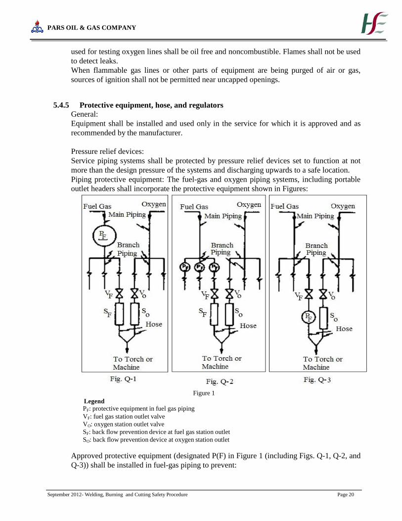
Piping protective equipment: The fuel-gas and oxygen piping systems, including portable
outlet headers shall incorporate the protective equipment shown in Figures:
Legend
Figure 1
PF: protective equipment in fuel gas piping
VF: fuel gas station outlet valve VO: oxygen station outlet valve SF: back flow prevention device at fuel gas station outlet SO: back flow prevention device at oxygen station outlet
Approved protective equipment (designated P(F) in Figure 1 (including Figs. Q-1, Q-2, and
Q-3)) shall be installed in fuel-gas piping to prevent:

PARS OIL & GAS COMPANY
September 2012- Welding, Burning and Cutting Safety Procedure Page 21
Backflow of oxygen into the fuel-gas supply system;
Passage of a flash back into the fuel-gas supply system; and
Excessive back pressure of oxygen in the fuel-gas supply system. The three functions of the
protective equipment may be combined in one device or may be provided by separate
devices.
The protective equipment shall be located in the main supply line, as in Figure Q-1 or at the
head of each branch line, as in Figure Q-2 or at each location where fuel-gas is withdrawn,
as in Figure Q-3. Where branch lines are of 2-inch pipe size or larger or of substantial
length, protective equipment (designated as P(F)) shall be located as shown in either Q-2
and Q-3.
Backflow protection shall be provided by an approved device that will prevent oxygen from
flowing into the fuel-gas system or fuel from flowing into the oxygen system (see Figs. Q-1
and Q-2)
Flash-back protection shall be provided by an approved device that will prevent flame from
passing into the fuel-gas system.
Back-pressure protection shall be provided by an approved pressure-relief device set at a
pressure not greater than the pressure rating of the backflow or the flashback protection
device, whichever is lower. The pressure-relief device shall be located on the downstream
side of the backflow and flashback protection devices. The vent from the pressure-relief
device shall be at least as large as the relief device inlet and shall be installed without low
points that may collect moisture. If low points are unavoidable, drip pots with drains closed
with screw plugs or caps shall be installed at the low points. The vent terminus shall not
endanger personnel or property through gas discharge; shall be located away from ignition
sources; and shall terminate in a hood or bend.
If pipeline protective equipment incorporates a liquid, the liquid level shall be maintained,
and suitable antifreeze may be used to prevent freezing.
Fuel gas for use with equipment not requiring oxygen shall be withdrawn upstream of the
piping protective devices.
Station outlet protective equipment:
A check valve, pressure regulator, hydraulic seal, or combination of these devices shall be
provided at each station outlet, including those on portable headers, to prevent backflow, as
shown in Figures Q-1, Q-2, and Q-3 and designated as S(F) and S(O).
When approved pipeline protective equipment (designated P(F)) is located at the station
outlet as in Figure Q-3, no additional check valve, pressure regulator, or hydraulic seal is
required.
A shutoff valve (designated V(F) and V(O)) shall be installed at each station outlet and
shall be located on the upstream side of other station outlet equipment.
If the station outlet is equipped with a detachable regulator, the outlet regulator, the outlet
shall terminate in a union connection that complies with the Regulator Connection
Standards, 1958, Compressed Gas Association.
If the station outlet is connected directly to a hose, the outlet shall terminate in a union
connection complying with the Standard Hose Connection Specifications, 1957,
Compressed Gas Association.
Station outlets may terminate in pipe threads to which permanent connections are to be
made, such as to a machine.

PARS OIL & GAS COMPANY
September 2012- Welding, Burning and Cutting Safety Procedure Page 22
Station outlets shall be equipped with a detachable outlet seal cap secured in place. This
cap shall be used to seal the outlet except when a hose, a regulator, or piping is attached.
Where station outlets are equipped with approved backflow and flashback protective
devices, as many as four torches may be supplied from one station outlet through rigid
piping, provided each outlet from such piping is equipped with a shutoff valve and
provided the fuel-gas capacity of any one torch does not exceed 15 cubic feet (0.42 m(3)
per hour...1910.253(e)(5)
Hose and hose connections: Hose for oxy-fuel gas service shall comply with the
Specification for Rubber Welding Hose, 1958, Compressed Gas Association and Rubber
Manufacturers Association:
When parallel lengths of oxygen and acetylene hose are taped together for convenience and
to prevent tangling, not more than 4 inches (10.2 cm) out of 12 inches (30.5 cm) shall be
covered by tape.
Hose connections shall comply with the Standard Hose Connection Specifications, 1957,
Compressed Gas Association.
Hose connections shall be clamped or otherwise securely fastened in a manner that will
withstand, without leakage, twice the pressure to which they are normally subjected in
service, but in no case less than a pressure of 300 psi (2.04 MPa). Oil-free air or an oil-free
inert gas shall be used for the test.
Hose showing leaks, burns, worn places, or other defects rendering it unfit for service shall
be repaired or replaced.
Pressure-reducing regulators:
Pressure-reducing regulators shall be used only for the gas and pressures for which they are
intended. The regulator inlet connections shall comply with Regulator Connection
Standards, 1958, Compressed Gas Association.
When regulators or parts of regulators, including gages, need repair, the work shall be
performed by skilled mechanics who have been properly instructed.
Gages on oxygen regulators shall be marked "USE NO OIL."
Union nuts and connections on regulators shall be inspected before use to detect faulty
seats which may cause leakage of gas when the regulators are attached to the cylinder
valves.
5.4.6 Acetylene generators
Approval and marking: Generators shall be of approved construction and shall be plainly
marked with the maximum rate of acetylene in cubic feet per hour for which they are
designed; the weight and size of carbide necessary for a single charge; the manufacturer's
name and address; and the name or number of the type of generator.
Carbide shall be of the size marked on the generator nameplate.
Rating and pressure limitations:
The total hourly output of a generator shall not exceed the rate for which it is approved and
marked. Unless specifically approved for higher ratings, carbide-feed generators shall be

PARS OIL & GAS COMPANY
September 2012- Welding, Burning and Cutting Safety Procedure Page 23
rated at 1 cubic foot (0.028 m(3)) per hour per pound of carbide required for a single
complete charge.
Relief valves shall be regularly operated to insure proper functioning. Relief valves for
generating chambers shall be set to open at a pressure not in excess of 15 psig (103 kPa
gauge pressure). Relief valves for hydraulic back pressure valves shall be set to open at a
pressure not in excess of 20 psig (137 kPa gauge pressure).
Non-automatic generators shall not be used for generating acetylene at pressures exceeding
1 psig (7 kPa gauge pressure), and all water overflows shall be visible.
Location: The space around the generator shall be ample for free, unobstructed operation
and maintenance and shall permit ready adjustment and charging.
Stationary acetylene generators (automatic and Non-automatic): The foundation shall be so
arranged that the generator will be level and so that no excessive strain will be placed on
the generator or its connections. Acetylene generators shall be grounded.
Generators shall be placed where water will not freeze. The use of common salt (sodium
chloride) or other corrosive chemicals for protection against freezing is not permitted.
Except when generators are prepared in accordance with following paragraphs of this
section, sources of ignition shall be prohibited in outside generator houses or inside
generator rooms.
Water shall not be supplied through a continuous connection to the generator except when
the generator is provided with an adequate open overflow or automatic water shutoff which
will effectively prevent overfilling of the generator. Where a non-continuous connection is
used, the supply line shall terminate at a point not less than 2 inches (5 cm) above the
regularly provided opening for filling so that the water can be observed as it enters the
generator.
Unless otherwise specifically approved, generators shall not be fitted with continuous drain
connections leading to sewers, but shall discharge through an open connection into a
suitably vented outdoor receptacle or residue pit which may have such connections. An
open connection for the sludge draw off is desirable to enable the generator operator to
observe leakage of generating water from the drain valve or sludge cock.
Each generator shall be provided with a vent pipe.
The escape or relief pipe shall be rigidly installed without traps and so that any
condensation will drain back to the generator.
The escape or relief pipe shall be carried full size to a suitable point outside the building. It
shall terminate in a hood or bend located at least 12 feet (3.7 m) above the ground,
preferably above the roof, and as far away as practicable from windows or other openings
into buildings and as far away as practicable from sources of ignition such as flues or
chimneys and tracks used by locomotives. Generating chamber relief pipes shall not be
inter-connected but shall be separately led to the outside air. The hood or bend shall be so
constructed that it will not be obstructed by rain, snow, ice, insects, or birds. The outlet
shall be at least 3 feet (0.9 m) from combustible construction.
Gas holders shall be constructed on the gas meter principle, the bell being suitably guided.
The gas bell shall move freely without tendency to bind and shall have a clearance of at
least 2 inches (5 cm) from the shell.

PARS OIL & GAS COMPANY
September 2012- Welding, Burning and Cutting Safety Procedure Page 24
The gas holder may be located in the generator room, in a separate room or out of doors. In
order to prevent collapse of the gas bell or infiltration of air due to a vacuum caused by the
compressor or booster pump or cooling of the gas, a compressor or booster cutoff shall be
provided at a point 12 inches (0.3 m) or more above the landing point of the bell. When the
gas holder is located indoors, the room shall be ventilated in accordance with following
paragraphs of this section and heated.
When the gas holder is not located within a heated building, gas holder seals shall be
protected against freezing.
Means shall be provided to stop the generator-feeding mechanism before the gas holder
reaches the upper limit of its travel.
When the gas holder is connected to only one generator, the gas capacity of the holder shall
be not less than one-third of the hourly rating of the generator.
If acetylene is used from the gas holder without increase in pressure at some points but with
increase in pressure by a compressor or booster pump at other points, approved piping
protective devices shall be installed in each supply line. The low-pressure protective device
shall be located between the gas holder and the shop piping, and the medium-pressure
protective device shall be located between the compressor or booster pump and the shop
piping (see Figure 2 (Q-4)). Approved protective equipment (designated P(F)) is used to
prevent: Backflow of oxygen into the fuel-gas supply system; passage of a flashback into
the fuel-gas supply system; and excessive back pressure of oxygen in the fuel-gas supply
system. The three functions of the protective equipment may be combined in one device or
may be provided by separate devices.
Figure 2

PARS OIL & GAS COMPANY
September 2012- Welding, Burning and Cutting Safety Procedure Page 25
The compressor or booster system shall be of an approved type.
Compressors and booster pump equipment shall be located in well-ventilated areas away
from open flames, electrical or mechanical sparks, or other ignition sources.
Compressor or booster pumps shall be provided with pressure relief valves which will
relieve pressure exceeding 15 psig (103 kPa gauge pressure) to a safe outdoor location as
provided in this procedure, or by returning the gas to the inlet side or to the gas supply
source.
Compressor or booster pump discharge outlets shall be provided with approved protective
equipment.
Portable acetylene generators: All portable generators shall be of a type approved for
portable use.
Portable generators shall not be used within 10 feet (3 m) of combustible material other
than the floor.
Portable generators shall not be used in rooms of total volume less than 35 times the total
gas-generating capacity per charge of all generators in the room. Generators shall not be
used in rooms having a ceiling height of less than 10 feet (3 m). (To obtain the gas-
generating capacity in cubic feet per charge, multiply the pounds of carbide per charge by
4.5.)
Portable generators shall be protected against freezing. The use of salt or other corrosive
chemical to prevent freezing is prohibited.
Portable generators shall be cleaned and recharged and the air mixture blown off outside
buildings.
When charged with carbide, portable generators shall not be moved by crane or derrick.
When not in use, portable generators shall not be stored in rooms in which open flames are
used unless the generators contain no carbide and have been thoroughly purged of
acetylene. Storage rooms shall be well ventilated.
When portable acetylene generators are to be transported and operated on vehicles, they
shall be securely anchored to the vehicles. If transported by truck, the motor shall be turned
off during charging, cleaning, and generating periods.
Portable generators shall be located at a safe distance from the welding position so that they
will not be exposed to sparks, slag, or misdirection of the torch flame or overheating from
hot materials or processes.
Outside generator houses and inside generator rooms for stationary acetylene generators.
No opening in any outside generator house shall be located within 5 feet (1.5 m) of any
opening in another building.
Walls, floors, and roofs of outside generator houses shall be of noncombustible
construction.
When a part of the generator house is to be used for the storage or manifolding of oxygen
cylinders, the space to be so occupied shall be separated from the generator or carbide
storage section by partition walls continuous from floor to roof or ceiling, of the type of
construction stated in following paragraphs of this section. Such separation walls shall be
without openings and shall be joined to the floor, other walls and ceiling or roof in a
manner to affect a permanent gas-tight joint.
Exit doors shall be located so as to be readily accessible in case of emergency.

PARS OIL & GAS COMPANY
September 2012- Welding, Burning and Cutting Safety Procedure Page 26
Explosion venting for outside generator houses and inside generator rooms shall be
provided in exterior walls or roofs. The venting areas shall be equal to not less than 1
square foot (0.09 m(2)) per 50 cubic feet (1.4 m(3)) of room volume and may consist of any
one or any combination of the following:
Walls of light, noncombustible material preferably single-thickness, single-strength glass;
lightly fastened hatch covers; lightly fastened swinging doors in exterior walls opening
outward; lightly fastened walls or roof designed to relieve at a maximum pressure of 25
pounds per square foot (0.001 MPa).
The installation of acetylene generators within buildings shall be restricted to buildings not
exceeding one story in height; Provided, however, that this will not be construed as
prohibiting such installations on the roof or top floor of a building exceeding such height.
Generators installed inside buildings shall be enclosed in a separate room.
The walls, partitions, floors, and ceilings of inside generator rooms shall be of
noncombustible construction having a fire-resistance rating of at least 1 hour. The walls or
partitions shall be continuous from floor to ceiling and shall be securely anchored. At least
one wall of the room shall be an exterior wall.
Openings from an inside generator room to other parts of the building shall be protected by
a swinging type, self-closing fire door for a Class B opening and having a rating of at least
1 hour. Windows in partitions shall be wired glass and approved metal frames with fixed
sash. Installation shall be in accordance with the Standard for the Installation of Fire Doors
and Windows, NFPA 80-1970.
Inside generator rooms or outside generator houses shall be well ventilated with vents
located at floor and ceiling levels.
Heating shall be by steam, hot water, enclosed electrically heated elements or other indirect
means. Heating by flames or fires shall be prohibited in outside generator houses or inside
generator rooms, or in any enclosure communicating with them.
Generator houses or rooms shall have natural light during daylight hours. Where artificial
lighting is necessary it shall be restricted to electric lamps installed in a fixed position.
Unless specifically approved for use in atmospheres containing acetylene, such lamps shall
be provided with enclosures of glass or other noncombustible material so designed and
constructed as to prevent gas vapors from reaching the lamp or socket and to resist
breakage. Rigid conduit with threaded connections shall be used.
Lamps installed outside of wired-glass panels set in gas-tight frames in the exterior walls or
roof of the generator house or room are acceptable.
Electric switches, telephones, and all other electrical apparatus which may cause a spark,
unless specifically approved for use inside acetylene generator rooms, shall be located
outside the generator house or in a room or space separated from the generator room by a
gas-tight partition, except that where the generator system is designed so that no carbide fill
opening or other part of the generator is open to the generator house or room during the
operation of the generator, and so that residue is carried in closed piping from the residue
discharge valve to a point outside the generator house or room, electrical equipment in the
generator house or room shall conform to the provisions of Subpart S of this part for Class
I, Division 2 locations.
Maintenance and operation:
PARS OIL & GAS COMPANY
September 2012- Welding, Burning and Cutting Safety Procedure Page 27
Unauthorized persons shall not be permitted in outside generator houses or inside generator
rooms.
Operating instructions shall be posted in a conspicuous place near the generator or kept in a
suitable place available for ready reference.
When recharging generators the order of operations specified in the instructions supplied by
the manufacturer shall be followed.
In the case of batch-type generators, when the charge of carbide is exhausted and before
additional carbide is added, the generating chamber shall always be flushed out with water,
renewing the water supply in accordance with the instruction card furnished by the
manufacturer.
The water-carbide residue mixture drained from the generator shall not be discharged into
sewer pipes or stored in areas near open flames. Clear water from residue settling pits may
be discharged into sewer pipes.
The carbide added each time the generator is recharged shall be sufficient to refill the space
provided for carbide without ramming the charge. Steel or other ferrous tools shall not be
used in distributing the charge.
Generator water chambers shall be kept filled to proper level at all times except while
draining during the recharging operation.
Whenever repairs are to be made or the generator is to be charged or carbide is to be
removed, the water chamber shall be filled to the proper level.
Previous to making repairs involving welding, soldering, or other hot work or other
operations which produce a source of ignition, the carbide charge and feed mechanism shall
be completely removed. All acetylene shall be expelled by completely flooding the
generator shell with water and the generator shall be disconnected from the piping system.
The generator shall be kept filled with water, if possible, or positioned to hold as much
water as possible.
Hot repairs shall not be made in a room where there are other generators unless all the
generators and piping have been purged of acetylene.
5.4.7 Transporting, moving and storing compressed gas cylinders
Valve protection caps shall be in place and secure. Oil shall not be used to lubricate
protection caps.
When cylinders are hoisted, they shall be secured on a cradle, slingboard or pallet. They
shall not be hoisted by means of magnets or choker slings.
Cylinders shall be moved by tilting and rolling them on their bottom edges. They shall not
be intentionally dropped, struck, or permitted to strike each other violently.
When cylinders are transported by vehicle, they shall be secured in position.
Valve protection caps shall not be used for lifting cylinders from one vertical position to
another. Bars shall not be used under valves or valve protection caps to pry cylinders loose
when frozen. Warm, not boiling, water shall be used to thaw cylinders loose.
Unless cylinders are firmly secured on a special carrier intended for this purpose, regulators
shall be removed and valve protection caps put in place before cylinders are moved.
A suitable cylinder truck, chain, or other steadying device shall be used to keep cylinders
from being knocked over while in use.

PARS OIL & GAS COMPANY
September 2012- Welding, Burning and Cutting Safety Procedure Page 28
When work is finished, when cylinders are empty or when cylinders are moved at any time,
the cylinder valves shall be closed.
Acetylene cylinders shall be secured in an upright position at all times except, if necessary,
for short periods of time while cylinders are actually being hoisted or carried.
5.4.8 Placing cylinders
Cylinders shall be kept far enough away from the actual welding or cutting operation so
that sparks, hot slag or flame will not reach them. When this is impractical, fire resistant
shields shall be provided.
Cylinders shall be placed where they cannot become part of an electrical circuit. Electrodes
shall not be struck against a cylinder to strike an arc.
Fuel gas cylinders shall be placed with valve end up whenever they are in use. They shall
not be placed in a location where they would be subject to open flame, hot metal, or other
sources of artificial heat.
Cylinders containing oxygen or acetylene or other fuel gas shall not be taken into confined
spaces.
5.4.9 Treatment of cylinders
Cylinders, whether full or empty, shall not be used as rollers or supports.
No person other than the gas supplier shall attempt to mix gases in a cylinder. No one
except the owner of the cylinder or person authorized by him shall refill a cylinder. No one
shall use a cylinder's contents for purposes other than those intended by the supplier. Only
cylinders bearing Interstate Commerce Commission identification and inspection markings
shall be used.
No damaged or defective cylinder shall be used.
Use of fuel gas: The employer shall thoroughly instruct employees in the safe use of fuel
gas, as follows:
Before connecting a regulator to a cylinder valve, the valve shall be opened slightly and
closed immediately. (This action is generally termed "cracking" and is intended to clear the
valve of dust or dirt that might otherwise enter the regulator.) The person cracking the
valve shall stand to one side of the outlet, not in front of it. The valve of a fuel gas cylinder
shall not be cracked where the gas would reach welding work, sparks, flame or other
possible sources of ignition.
The cylinder valve shall always be opened slowly to prevent damage to the regulator. To
permit quick closing, valves on fuel gas cylinders shall not be opened more than 1 1/2
turns. When a special wrench is required, it shall be left in position on the stem of the valve
while the cylinder is in use so that the fuel gas flow can be shut off quickly in case of an
emergency. In the case of manifold or coupled cylinders, at least one such wrench shall
always be available for immediate use. Nothing shall be placed on top of a fuel gas
cylinder, when in use, which may damage the safety device or interfere with the quick
closing of the valve.
Fuel gas shall not be used from cylinders through torches or other devices which are
equipped with shut-off valves without reducing the pressure through a suitable regulator
attached to the cylinder valve or manifold.
PARS OIL & GAS COMPANY
September 2012- Welding, Burning and Cutting Safety Procedure Page 29
Before a regulator is removed from a cylinder valve, the cylinder valve shall always be
closed and the gas released from the regulator.
If, when the valve on a fuel gas cylinder is opened, there is found to be a leak around the
valve stem, the valve shall be closed and the gland nut tightened. If this action does not
stop the leak, the use of the cylinder shall be discontinued, and it shall be properly tagged
and removed from the vessel. In the event that fuel gas should leak from the cylinder valve
rather than from the valve stem and the gas cannot be shut off, the cylinder shall be
properly tagged and removed from the vessel. If a regulator attached to a cylinder valve will
effectively stop a leak through the valve seat, the cylinder need not be removed from the
vessel.
If a leak should develop at a fuse plug or other safety device, the cylinder shall be removed
from the vessel
5.4.10 Fuel gas and oxygen manifolds
Fuel gas and oxygen manifolds shall bear the name of the substance they contain in letters
at least one (1) inch high which shall be either painted on the manifold or on a sign
permanently attached to it.
Fuel gas and oxygen manifolds shall be placed in safe and accessible locations in the open
air. They shall not be located within enclosed spaces.
Manifold hose connections, including both ends of the supply hose that lead to the
manifold, shall be such that the hose cannot be interchanged between fuel gas and oxygen
manifolds and supply header connections. Adapters shall not be used to permit the
interchange of hose. Hose connections shall be kept free of grease and oil.
When not in use, manifold and header hose connections shall be capped.
Nothing shall be placed on top of a manifold, when in use, which will damage the manifold
or interfere with the quick closing of the valves.
Hose:
Fuel gas hose and oxygen hose shall be easily distinguishable from each other. The contrast
may be made by different colors or by surface characteristics readily distinguishable by the
sense of touch. Oxygen and fuel has hoses shall not be interchangeable. A single hose
having more than one gas passage, a wall failure of which would permit the flow of one gas
into the other gas passage, shall not be used.
When parallel sections of oxygen and fuel gas hose are taped together not more than 4
inches out of 8 inches shall be covered by tape.
All hose carrying acetylene, oxygen, natural or manufactured fuel gas, or any gas or
substance which may ignite or enter into combustion or be in any way harmful to
employees, shall be inspected at the beginning of each shift. Defective hose shall be
removed from service.
Hose which has been subjected to flashback or which shows evidence of severe wear or
damage shall be tested to twice the normal pressure to which it is subject, but in no case
less than two hundred (200) psi. Defective hose or hose in doubtful condition shall not be
used.
Hose couplings shall be of the type that cannot be unlocked or disconnected by means of a
straight pull without rotary motion.
Boxes used for the stowage of gas hose shall be ventilated.

PARS OIL & GAS COMPANY
September 2012- Welding, Burning and Cutting Safety Procedure Page 30
Torches:
Clogged torch tip openings shall be cleaned with suitable cleaning wires, drills or other
devices designed for such purpose.
Torches shall be inspected at the beginning of each shift for leaking shutoff valves, hose
couplings, and tip connections. Defective torches shall not be used.
Torches shall be lighted by friction lighters or other approved devices, and not by matches
or from hot work.
Pressure regulators: Oxygen and fuel gas pressure regulators including their related gauges
shall be in proper working order while in use.
5.4.11 Light Up Procedure It is important that an adequate flow of fuel gas is issuing from the nozzle of the torch or
other apparatus before lighting up.
Personnel must use the following procedures:
• Set the regulators to the recommended working pressure.
• Flash back arrestors must be fitted close to the torch i.e. within 0.5 m.
• Keep the torch nozzle away from any source of ignition until the fuel gas is flowing
freely from the nozzle.
• Use a spark lighter for igniting the torch.
If the torch flashes back on lighting up it is because the regulators are not set to the correct
pressure or a light has been applied before the flow of fuel gas is properly established.
If the flame snaps out when the torch is in use, it is because:
• Regulator pressure and/or gas flow are incorrect, either too high or too low.
• The nozzle has been obstructed.
• The nozzle has been held too close to the work.
• The nozzle has become overheated.
In the last case, completely shut off both torch valves. Plunge the nozzle and torch head
into water. Make sure that the nozzle is tight before re-lighting torch. Check the regulator
setting and cylinder pressures then re-light in accordance with the above procedure.
5.4.12 Ventilation and Breathing Apparatus for Gas Welding
The application of an oxy-propane flame to sheet metal, coated with metallic lead, zinc,
lead paints or other injurious substances, may give rise to highly toxic vapors, particularly
in cutting work where an excess of oxygen is required. For such work suitable air line
breathing apparatus (NOT canister respiration) must be worn.
Unless there is good through ventilation, an air-line breathing apparatus mask must be worn
when carrying out oxy-propane cutting or welding in a confined space. Ventilation is better
effected by extraction fans/air movers than by blowing fresh air into the confined space.
Compressed oxygen must never be used for ventilating purposes, or be blown through
propane piping.
Cylinders of compressed gas must always be kept outside any enclosed space where
welding/cutting is taking place.
5.4.13 Work interruption

PARS OIL & GAS COMPANY
September 2012- Welding, Burning and Cutting Safety Procedure Page 31
Torches and hoses must not be left in vessels, or enclosed spaces, when they are not in use,
e.g. after use, during a lunch break, or overnight. A very small leak of any gas, particularly
propane from a torch over such a period, can make the atmosphere in the vessel dangerous.
Where this cannot be done the oxygen and propane connections MUST BE
DISCONNECTED at the cylinders situated outside the vessel (turning off the valves is not
sufficient).
5.4.14 Repairs to Small Containers
This includes the welding, brazing, soldering or cutting of drums, or containers (e.g. 40
gallon drums, fuel tanks of vehicles) which have contained petroleum products, flammable
or other combustible materials.
Before any such work is carried out, the drum or container must be uncapped and drained
and then either thoroughly steamed cleaned or submerged in boiling water and kept at the
boiling point for at least one hour.
After the steaming or boiling process, compressed air must be blown through the drum
container until the vapors are removed (ensuring that the air has a free exit to prevent build
up of pressure).
Before carrying out the hot work, the drum or container must be certified "Gas Free" and a
valid Main Work Permit (Hot) must be issued.
When burning or welding is in progress on a small vessel un-burnt gases can collect inside
and an explosive mixture can be formed.
Compressed air or steam must be passed through the vessel, care being taken to ensure free
and adequate exit for the air or steam.
Compressed oxygen must not be used for purging.
The following methods are considered INADEQUATE by themselves for preparing vessels
for repair:
• Washing out with hot or cold water allowing water to run through.
• Purging with compressed air.
• Cleaning by means of solvents, such as trichloroethylene.
All vessels sent to the workshop for repair must be certified free of gas and corrosive
chemicals.
5.5 Electric Arc Welding and Burning
Electrical Supply and Connections - see fig. 3
All welding sets, cables, connectors and terminations must be maintained in good
condition.
Electrical supply and earthing connections, to welding transformers and generator sets,
must be made, maintained (and condemned if necessary) by a competent electrician.
WELDING TRANSFORMERS SHOULD BE PROVIDED WITH A EARTH
CONNECTION (casing and neutral terminal of primary windings).

PARS OIL & GAS COMPANY
September 2012- Welding, Burning and Cutting Safety Procedure Page 32
All supplies for welding equipment must be made with approved cables and approved plug
boxes and must be controlled from a circuit which includes protection sensitive to earth
fault currents.
Where stationary transformers or generator sets are being used, a suitable switch must be
mounted adjacent to the equipment to isolate it from the supply main.
5.5.1 General
Equipment selection: Welding equipment shall be chosen for safe application to the work
to be done as specified in before.
Installation: Welding equipment shall be installed safely as specified in before.
Instruction: Workmen designated to operate arc welding equipment shall have been
properly instructed and qualified to operate such equipment as specified in before.
5.5.2 Welding Leads
Portable transformers or generator sets having trailing leads must be provided with
interlocked fused switch sockets and plugs, protecting both trailing cable and equipment.
All leads must be properly terminated and lead cable couplers and terminations must be of
adequate current carrying capacity.
To avoid long lengths of power cables, the machine must be sited as close as possible to the
power supply points.
A welding return lead must be provided from the neutral terminal of each phase of an AC
welding transformer or from the negative terminal of a DC generator to the work piece.
THIS RETURN LEAD IS NOT PROVIDING AN EARTH CONNECTION.
THIS LEAD IS REQUIRED IN ADDITION TO THE EARTH BONDING OF THE
WORK PIECE. It should be located as close as possible from the work place.
The connections at the work piece must be made by bolting or clamping firmly.
Where more than one operator is working from the same welding machine, the polarity of
each welding lead and welding return must be the same.
Where two or more leads are being used in a confined area, the corresponding leads must
be paired and, as far as possible, the crossing of pairs with one another, or with any single
lead, must be avoided.
Where welding leads trail near tanks or sumps containing hydrocarbons, additional lengths
of cable must be added to the circuit to avoid the danger area.
5.5.3 Application of arc welding equipment
General: Assurance of consideration of safety in design is obtainable by choosing apparatus
complying with the Requirements for Electric Arc-Welding Apparatus, NEMA EW-1-
1962, National Electrical Manufacturers Association or the Safety Standard for
Transformer-Type Arc-Welding Machines, ANSI C33.2-1956, and Underwriters’
Laboratories, both of which are incorporated by reference as specified in Sec. 1910.6.
5.5.4 Environmental conditions
Standard machines for arc welding service shall be designed and constructed to carry their
rated load with rated temperature rises where the temperature of the cooling air does not

PARS OIL & GAS COMPANY
September 2012- Welding, Burning and Cutting Safety Procedure Page 33
exceed 40 deg. C. (104 deg. F.) and where the altitude does not exceed 3,300 feet (1,005.8
m), and shall be suitable for operation in atmospheres containing gases, dust, and light rays
produced by the welding arc.
Unusual service conditions may exist, and in such circumstances machines shall be
especially designed to safely meet the requirements of the service. Chief among these
conditions are:
• Exposure to unusually corrosive fumes
• Exposure to steam or excessive humidity
• Exposure to excessive oil vapor
• Exposure to flammable gases
• Exposure to abnormal vibration or shock
• Exposure to excessive dust
• Exposure to weather
• Exposure to unusual seacoast or shipboard conditions
5.5.5 Voltage
The following limits shall not be exceeded:
Alternating-current machines
Manual arc welding and cutting - 80 volts
Automatic (machine or mechanized) arc welding and cutting - 100 volts
Direct-current machines
Manual arc welding and cutting - 100 volts
Automatic (machine or mechanized) arc welding and cutting - 100 volts
When special welding and cutting processes require values of open circuit voltages higher
than the above, means shall be provided to prevent the operator from making accidental
contact with the high voltage by adequate insulation or other means.
For a.c. welding under wet conditions or warm surroundings where perspiration is a factor,
the use of reliable automatic controls for reducing no load voltage is recommended to
reduce the shock hazard.
5.5.6 Design
A controller integrally mounted in an electric motor driven welder shall have capacity for
carrying rated motor current, shall be capable of making and interrupting stalled rotor
current of the motor, and may serve as the running over current device if provided with the
number of over current units as specified in before.
On all types of arc welding machines, control apparatus shall be enclosed except for the
operating wheels, levers, or handles.
Input power terminals, tap change devices and live metal parts connected to input circuits
shall be completely enclosed and accessible only by means of tools.
Terminals for welding leads should be protected from accidental electrical contact by
personnel or by metal objects i.e., vehicles, crane hooks, etc. Protection may be obtained by
use of: Dead-front receptacles for plug connections; recessed openings with no removable
hinged covers; heavy insulating sieving or taping or other equivalent electrical and
mechanical protection. If a welding lead terminal which is intended to be used exclusively
for connection to the work is connected to the grounded enclosure, it must be done by a

PARS OIL & GAS COMPANY
September 2012- Welding, Burning and Cutting Safety Procedure Page 34
conductor at least two AWG sizes smaller than the grounding conductor and the terminal
shall be marked to indicate that it is grounded.
No connections for portable control devices such as push buttons to be carried by the
operator shall be connected to an a.c. circuit of higher than 120 volts. Exposed metal parts
of portable control devices operating on circuits above 50 volts shall be grounded by a
grounding conductor in the control cable.
Auto transformers or a.c. reactors shall not be used to draw welding current directly from
any a.c. power source having a voltage exceeding 80 volts.
5.5.7 Installation of arc welding equipment
General: Installation including power supply shall be in accordance with the requirements
of bellow:
Grounding: The frame or case of the welding machine (except engine-driven machines
shall be grounded under the conditions and according to the methods prescribed in this
procedure.
Conduits containing electrical conductors shall not be used for completing a work-lead
circuit. Pipelines shall not be used as a permanent part of a work-lead circuit, but may be
used during construction, extension or repair providing current is not carried through
threaded joints, flanged bolted joints, or caulked joints and those special precautions are
used to avoid sparking at connection of the work-lead cable.
Chains, wire ropes, cranes, hoists, and elevators shall not be used to carry welding current.
Where a structure, conveyor, or fixture is regularly employed as a welding current return
circuit, joints shall be bonded or provided with adequate current collecting devices.
All ground connections shall be checked to determine that they are mechanically strong and
electrically adequate for the required current.
Supply connections and conductors:
A disconnecting switch or controller shall be provided at or near each welding machine
which is not equipped with such a switch or controller mounted as an integral part of the
machine. Over current protection shall be provided also. A disconnect switch with overload
protection or equivalent disconnect and protection means, by this procedure requirements,
shall be provided for each outlet intended permitted for connection to a portable welding
machine.
For individual welding machines, the rated current-carrying capacity of the supply
conductors shall be not less than the rated primary current of the welding machines.
For groups of welding machines, the rated current-carrying capacity of conductors may be
less than the sum of the rated primary currents of the welding machines supplied. The
conductor rating shall be determined in each case according to the machine loading based
on the use to be made of each welding machine and the allowance permissible in the event
that all the welding machines supplied by the conductors will not be in use at the same
time.
In operations involving several welders on one structure, d.c. welding process requirements
may require the use of both polarities; or supply circuit limitations for a.c. welding may
require distribution of machines among the phases of the supply circuit. In such cases no
load voltages between electrode holders will be 2 times normal in d.c. or 1, 1.41, 1.73, or 2

PARS OIL & GAS COMPANY
September 2012- Welding, Burning and Cutting Safety Procedure Page 35
times normal on a.c. machines. Similar voltage differences will exist if both a.c. and d.c.
welding are done on the same structure.
All d.c. machines shall be connected with the same polarity.
All a.c. machines shall be connected to the same phase of the supply circuit and with the
same instantaneous polarity.
5.5.8 Operation and maintenance
General: Workers assigned to operate or maintain arc welding equipment shall be
acquainted with the requirements of this section and with 1910.252 (a), (b), and (c) of this
part.
Machine hook up: Before starting operations all connections to the machine shall be
checked to make certain they are properly made. The work lead shall be firmly attached to
the work; magnetic work clamps shall be freed from adherent metal particles of spatter on
contact surfaces. Coiled welding cable shall be spread out before use to avoid serious
overheating and damage to insulation.
Grounding: Grounding of the welding machine frame shall be checked. Special attention
shall be given to safety ground connections of portable machines.
Leaks: There shall be no leaks of cooling water, shielding gas or engine fuel.
Switches: It shall be determined that proper switching equipment for shutting down the
machine is provided.
Manufacturers' instructions: Printed rules and instructions covering operation of equipment
supplied by the manufacturers shall be strictly followed.
Electrode holders: Electrode holders when not in use shall be so placed that they cannot
make electrical contact with persons, conducting objects, fuel or compressed gas tanks.
Electric shock: Cables with splices within 10 feet (3 m) of the holder shall not be used. The
Welder should not coil or loop welding electrode cable around parts of his body.
Maintenance :The operator should report any equipment defect or safety hazard to his
supervisor and the use of the equipment shall be discontinued until its safety has been
assured. Repairs shall be made only by qualified personnel.
Machines which have become wet shall be thoroughly dried and tested before being used.
Cables with damaged insulation or exposed bare conductors shall be replaced. Joining
lengths of work and electrode cables shall be done by the use of connecting means
specifically intended for the purpose. The connecting means shall have insulation adequate
for the service conditions.
5.5.9 Injurious Effects of Arc Radiation
The injurious effects of the radiation's from a welding arc on the eyes and skin are similar
whether DC or AC current is employed.
The effect of looking at an unscreened arc, at a considerable distance and for a few seconds
only, can cause a temporary or permanent eye injury, which may not become apparent until
some four to eight hour later.
Welders and any helpers must protect their eyes with the screens, goggles, or spectacles
provided. The work must also be effectively screened from other workers in the vicinity.

PARS OIL & GAS COMPANY
September 2012- Welding, Burning and Cutting Safety Procedure Page 36
Electric Supply and Connections (see Figure 3)
All welding sets, cables, connectors and terminations must be maintained in good
condition.
Electrical supply and earthing connections, to welding transformers and generator sets,
must be mad and, maintained (or condemned if necessary) by a competent electrician.
All supplies for welding equipment must be made with approved cables and plug boxes and
must be controlled from a circuit that includes protection sensitive to earth fault currents.
Where stationary transformers or generator sets are being used, a suitable switch must be
mounted adjacent to the equipment to isolate it from the mains supply.
FIGURE 3: WELDING CIRCUIT CONNECTIONS
5.5.10 Welding Leads
Portable transformers or generator sets that have trailing leads fitted, must be provided with
interlocked and fused switch sockets and plugs, protecting both trailing cable and
equipment.
All leads must be properly terminated. Lead cable couplers and terminations must be of
adequate current carrying capacity.
To avoid long lengths of power cables, the machine must be sited as close as possible to the
power supply points.
A welding return lead must be provided from the neutral terminal of each phase of an AC
welding transformer or from the negative terminal of a DC generator to the work piece.
This lead is required in addition to the earth bonding.
The connections at the work piece must be made by bolting, or clamping firmly, as near as
possible to the point at which welding is to take place.
Where more than one operator is working from the same welding machine, the polarity of
each welding lead and welding return must be the same.

PARS OIL & GAS COMPANY
September 2012- Welding, Burning and Cutting Safety Procedure Page 37
Where two or more leads are being used in a confined area, the corresponding leads must
be paired and, as far as possible, the crossing of pairs with one another, or with any single
lead, must be avoided.
Where welding leads may pass close to tanks or sumps containing hydrocarbons, additional
lengths of cable must be added to the circuit to avoid the danger area.
5.5.11 Earthing and Bonding
For all AC welding transformers, the transformer low voltage winding must not be earthed
but the transformer case must be effectively bonded to an earthing system adjacent to the
equipment.
For all AC driven welding generators, no earth connection may be applied to either pole of
the DC welding output.
The machine frame must be effectively bonded to earth.
5.6 Resistance welding
5.6.1 General
Installation: All equipment shall be installed by a qualified electrician in conformance with
this procedure. There shall be a safety-type disconnecting switch or a circuit breaker or
circuit interrupter to open each power circuit to the machine, conveniently located at or
near the machine, so that the power can be shut off when the machine or its controls are to
be serviced.
Thermal protection: Ignition tubes used in resistance welding equipment shall be equipped
with a thermal protection switch.
Personnel: Workmen designated to operate resistance welding equipment shall have been
properly instructed and judged competent to operate such equipment.
Guarding: Controls of all automatic or air and hydraulic clamps shall be arranged or
guarded to prevent the operator from accidentally activating them.
Spot and seam welding machines (non portable): Voltage: All external weld initiating
control circuits shall operate on low voltage, not over 120 volts, for the safety of the
operators.
Capacitor welding: Stored energy or capacitor discharge type of resistance welding
equipment and control panels involving high voltage (over 550 volts) shall be suitably
insulated and protected by complete enclosures, all doors of which shall be provided with
suitable interlocks and contacts wired into the control circuit (similar to elevator
interlocks). Such interlocks or contacts shall be so designed as to effectively interrupt
power and short circuit all capacitors when the door or panel is open. A manually operated
switch or suitable positive device shall be installed, in addition to the mechanical interlocks
or contacts, as an added safety measure assuring absolute discharge of all capacitors.
PARS OIL & GAS COMPANY
September 2012- Welding, Burning and Cutting Safety Procedure Page 38
Interlocks: All doors and access panels of all resistance welding machines and control
panels shall be kept locked and interlocked to prevent access, by unauthorized persons, to
live portions of the equipment.
Guarding: All press welding machine operations, where there is a possibility of the
operator's fingers being under the point of operation, shall be effectively guarded by the use
of a device such as an electronic eye safety circuit, two hand controls or protection similar
to that prescribed for punch press operation,. All chains, gears, operating bus linkage, and
belts shall be protected by adequate guards.
Shields: The hazard of flying sparks shall be, wherever practical, eliminated by installing a
shield guard of safety glass or suitable fire-resistant plastic at the point of operation.
Additional shields or curtains shall be installed as necessary to protect passing persons from
flying sparks.
Foot switches: All foot switches shall be guarded to prevent accidental operation of the
machine.
Stop buttons: Two or more safety emergency stop buttons shall be provided on all special
multi spot welding machines, including 2-post and 4-post weld presses.
Safety pins: On large machines, four safety pins with plugs and receptacles (one in each
corner) shall be provided so that when safety pins are removed and inserted in the ram or
platen, the press becomes inoperative.
Grounding: Where technically practical, the secondary of all welding transformers used in
multi spot, projection and seam welding machines shall be grounded. This may be done by
permanently grounding one side of the welding secondary current circuit. Where not
technically practical, a center tapped grounding reactor connected across the secondary or
the use of a safety disconnect switch in conjunction with the welding control are acceptable
alternates. Safety disconnect shall be arranged to open both sides of the line when welding
current is not present.
5.6.2 Portable welding machines
Counterbalance: All portable welding guns shall have suitable counterbalanced devices for
supporting the guns, including cables, unless the design of the gun or fixture makes
counterbalancing impractical or unnecessary.
Safety chains: All portable welding guns, transformers and related equipment that is
suspended from overhead structures, eye beams, trolleys, etc. shall be equipped with safety
chains or cables: Safety chains or cables shall be capable of supporting the total shock load
in the event of failure of any component of the supporting system.
Clevis: Each clevis shall be capable of supporting the total shock load of the suspended
equipment in the event of trolley failure.
PARS OIL & GAS COMPANY
September 2012- Welding, Burning and Cutting Safety Procedure Page 39
Switch guards: All initiating switches, including retraction and dual schedule switches,
located on the portable welding gun shall be equipped with suitable guards capable of
preventing accidental initiation through contact with fix Turing, operator's clothing, etc.
Initiating switch voltage shall not exceed 24 volts.
Moving holder: The movable holder, where it enters the gun frame, shall have sufficient
clearance to prevent the shearing of fingers carelessly placed on the operating movable
holder.
Grounding: The secondary and case of all portable welding transformers shall be grounded.
Secondary grounding may be by center tapped secondary or by a center tapped grounding
reactor connected across the secondary.
5.6.3 Flash welding equipment
Ventilation and flash guard: Flash welding machines shall be equipped with a hood to
control flying flash. In cases of high production, where materials may contain a film of oil
and where toxic elements and metal fumes are given off, ventilation shall be provided in
accordance with this procedure.
Fire curtains: For the protection of the operators of nearby equipment, fire-resistant curtains
or suitable shields shall be set up around the machine and in such a manner that the
operators movements are not hampered
5.6.4 Maintenance
Periodic inspection shall be made by qualified maintenance personnel, and a certification
record maintained. The certification record shall include the date of inspection, the
signature of the person who performed the inspection and the serial number, or other
identifier, for the equipment inspected. The operator shall be instructed to report any
equipment defects to his supervisor and the use of the equipment shall be discontinued
until safety repairs have been completed.
5.6.5 Preheating and heating during welding
For thick work pieces, preheating and heating during welding might be required to prevent
cracks. IF ELECTRICALLY HEATED COILS ARE USED, THEY SHALL BE
SUPPLIED THROUGH LOW VOLTAGE POWER SUPPLY (48 V OR 24 V IN WET
ATMOSPHERE).
If heating is undertaken by gas torch, the torch shall be kept in hand by a designated welder
helper. A lit torch should never be set down until turned off.

PARS OIL & GAS COMPANY
September 2012- Welding, Burning and Cutting Safety Procedure Page 40
6. DEFFINITION Welder" and "welding operator" mean any operator of electric or gas welding and cutting
equipment
7. REFERENCES
1. OSHA Standards (Occupational Health and Safety Administration) Ed:2007
Standard 29 CFR,1910.254,1910.251,1915.55,1910252,1915.12,1915.54,1910.255
2. OSHA Sampling and Analytical Methods – Ed:2007
3. ANSI Standard no B11.1 Ed:2001
4. NIOSH Standards (National Institute of Safety and Health) Ed:2007
5. B.S (British Standard) Ed:2004
6. ASME Standards (American Mechanical ) Ed:2003
7. ILO Standards (International Labor Office) Ed:2003
8. NFPA Standards (National Fire Protection Administration) Ed:2001
9. OEL Standards Ed: 1998
8. APPENDIX :
APPENDIX 1 . CHECK LIST

PARS OIL & GAS COMPANY
September 2012- Welding, Burning and Cutting Safety Procedure Page 41
APPENDIX 1 . CHECK LIST
BELOW ARE SOME ITEMS WHICH SHOULD BE CHECKED WHEN CONSIDERING WELDING AND
BURNING
No.
Description
Yes
No
N/A
Comments
1
Have the correct Permits to Work been raised ?
2
Could the operation be carried out in a less hazardous
area ?
3
Have toxic fumes been considered ? Is breathing
apparatus required ?
4
Is ventilation satisfactory ?
5
Have the welders etc. been made aware of the dangers of
fumes etc. ?
6
Is lead paint or zinc galvanised metal involved ? If so
how are the fumes controlled ?
7
Is the welder/burner aware of the hazards, etc. ?
8
Is there an approved welding Procedure ? Is the welder
qualified/approved ?
9
Has the appropriate gas checks been performed ?
10
Is a portable fire extinguisher available ?
11
Are other areas protected from sparks and hot slag, etc. ?
12
Have all places where hydrocarbon liquids may be
trapped been inspected ?
13
If the hot work is on the outside of a vessel/pipework is
there any possibility of ignition on the inside ?
14
Is the correct PPE being used ?
15
Is a spark igniter being used ?
16
Are flash-back arrestors in place close to the burning
torch ?
17
Are small containers certified as being clean before any
burning or welding takes place ?
18
Are welding cables connected within 3 m of the worksite
?
19
Have the trailing leads been inspected by a competent
electrician ?
20
Are both sides of the welding site protected from stray
currents ?

PARS OIL & GAS COMPANY
September 2012- Welding, Burning and Cutting Safety Procedure Page 42
SUGGESTIONS FOR THE POGC
WELDING, BURNING & CUTTING SAFETY PROCEDURE
MANAGER, HSE Department
Pars Oil & Gas Company
Tehran I.R. Iran
Please consider the following suggestion(s) relative to the POGC Welding, burning & cutting safety procedure:
(Signature)
(Date)
(Address)
Contact Telephone Number
Contact FAX Number