Embed Size (px)
Citation preview
Part 2: Deterioration of Structures
ROAD STRUCTURES INSPECTION MANUAL I
Road Structures Inspection Manual
Part 2: Deterioration of Structures Department of Planning, Transport and Infrastructure, South Australia
For further information regarding DPTI Road Structures Inspection Manual please contact:
The Principal Engineer Structures Road Assets Section Level 4, 77 Grenfell Street Adelaide SA 5000
www.dpti.sa.gov.au
RAMA Document No: RAMA-ST-PRC-048 Knet Document No: 14677930 Document version: 1.0 (21/10/2019)
Previously, this document was called the Bridge Inspection Manual. First published in 2003 then revised in 2005, 2008 and 2019.
Disclaimer Every effort has been made to supply complete and accurate information. This document is subject to continual revision and may change. It is the user’s responsibility to check DPTI’s website to ensure that the current version is being used.
This manual has been compiled based on material sourced from:
Ontario Ministry of Transportation, Ontario Structure Inspection Manual © The Queen's Printer for Ontario 2000 <https://www.library.mto.gov.on.ca/SydneyPLUS/Sydney/Portal/default.aspx?component=AAAAIY&record=2cc7e50c-3d41-4468-90f1-0788368ce945> licensed under the Open Government Licence – Ontario <https://www.ontario.ca/page/open-government-licence-ontario>
Department of Transport (Victoria), VicRoads Road Structures Inspection Manual – 2018 © State Government of Victoria (Department of Transport, VicRoads) 2018 <https://www.vicroads.vic.gov.au/business-and-industry/technical-publications/bridges-and-structures> used with permission
Department of Transport and Main Roads (Queensland), Structures Inspection Manual © State of Queensland (Department of Transport and Main Roads) 2016 <https://www.tmr.qld.gov.au/business-industry/Technical-standards-publications/Structures-Inspection-Manual> licensed under <https://creativecommons.org/licenses/by/3.0/au/>
Main Roads Western Australia, Inspection Guidelines Documents © Western Australian Government 2012-2017 <https://www.mainroads.wa.gov.au/BuildingRoads/StandardsTechnical/StructuresEngineering/Pages/Asset_Management.aspx#TOCh35> used with permission
and adjusted for South Australian conditions.
Copyright
This content is licensed under a Creative Commons Attribution 3.0 Australia Licence
© Government of South Australia (Department of Planning, Transport and Infrastructure) 2019
Feedback: Please send your feedback regarding this document to: [email protected]
Part 2: Deterioration of Structures
ROAD STRUCTURES INSPECTION MANUAL II
1 TABLE OF CONTENTS 1
1
1. MATERIAL DEFECTS 1
1.1 GENERAL 1
1.2 CONCRETE 2
1.2.1 Scaling 3
1.2.2 Disintegration 4
1.2.3 Corrosion of reinforcement 4
1.2.4 Delamination 5
1.2.5 Spalling 5
1.2.6 Cracking 6
1.2.7 Alkali Aggregate Reaction (AAR) 8
1.2.8 Surface Defects 9
1.3 STEEL 12
1.3.1 Corrosion 13
1.3.2 Permanent Deformations 14
1.3.3 Cracking 14
1.3.4 Loose Connections 18
1.3.5 Impact Damage 18
1.3.6 Fire Damage 18
1.4 MASONRY 19
1.4.1 Cracking 19
1.4.2 Splitting, spalling and disintegration 19
1.4.3 Loss of mortar and stones 20
1.4.4 Arch stones dropping 20
1.4.5 Side wall movement at masonry arch 20
1.4.6 Deformation 21
1.4.7 Separation of arch rings 21
1.5 TIMBER 21
1.5.1 Fungal Rot 21
1.5.2 Termites 22
1.5.3 Marine Organisms 23
1.5.4 Corrosion of Fasteners 24
1.5.5 Shrinkage and Splitting 24
1.5.6 Fire Damage 25
1.5.7 Flood Damage 26
1.6 CONDITION OF PROTECTIVE COATING 26
1.7 FIBRE REINFORCED POLYMERS (FRP) 30
2. COMMON CAUSES OF STRUCTURE DETERIORATION 31
2.1 CONCRETE BRIDGES 31
2.1.1 Monolithic and simply-supported T-beams 31
2.1.2 Precast ‘I’ beams 31
2.1.3 Precast prestressed inverted ‘T’ beams 32
2.1.4 Box girder bridges 32
Part 2: Deterioration of Structures
ROAD STRUCTURES INSPECTION MANUAL III
2.1.5 Prestressed voided flat slab bridges 32
2.1.6 Reinforced concrete flat slabs 32
2.1.7 Precast prestressed deck units 33
2.1.8 Precast prestressed voided ‘T’ beams 33
2.1.9 Decks and overlays 34
2.1.10 Diaphragms 34
2.1.11 Kerbs, footways, posts and railing 34
2.1.12 Abutments 35
2.1.13 Piers 36
2.2 STEEL BRIDGES 37
2.3 TIMBER BRIDGES 38
2.3.1 Decking 38
2.4 DECK JOINTS 40
2.4.1 Joint Defects 41
2.5 STEP (HALF) JOINTS 42
2.6 BEARINGS 43
2.7 CULVERTS 44
2.7.1 Concrete Box Culverts 44
2.7.2 Concrete Pipe Culverts 44
2.7.3 Masonry Arch Culverts 45
2.7.4 Corrugated Metal Structures - Pipes and Arch Culverts 45
2.8 MAJOR SIGN / GANTRY STRUCTURES 46
2.9 RETAINING WALLS 47
2.10 NOISE AND VISUAL SCREEN WALLS 47
2.11 FERRY RAMPS 48
2.12 BUSWAY 48
2.13 CATTLE GRIDS 48
2.14 TUNNELS 48
2.15 CAUSES OF DETERIORATION NOT RELATED TO CONSTRUCTION MATERIALS 49
2.15.1 Damage due to Accidents 49
2.15.2 Drainage 49
2.15.3 Debris 50
2.15.4 Vegetation 50
2.15.5 Waterway Scour 50
2.15.6 Movement of the Structure 51
2.15.7 Condition of Approaches 52
Part 2: Deterioration of Structures
ROAD STRUCTURES INSPECTION MANUAL IV
LIST OF TABLES Table 1: Crack Size (Width) Guide ...................................................................................................... 7
LIST OF FIGURES Figure 1: Concrete scaling .................................................................................................................. 3
Figure 2: Disintegration of concrete .................................................................................................. 4
Figure 3: Corrosion of reinforcement in concrete ............................................................................. 4
Figure 4: Corrosion of reinforcement in concrete ............................................................................. 4
Figure 5: Delamination in culvert slab................................................................................................ 5
Figure 6: Spalling of concrete at ends of deck units .......................................................................... 5
Figure 7: Spalling to front face of headstock ..................................................................................... 5
Figure 8: Cracking in concrete bridge structures ............................................................................... 6
Figure 9: Accurate measurement of crack width ............................................................................... 8
Figure 10: Concrete affected by alkali aggregate reaction (AAR) ...................................................... 8
Figure 11: Concrete segregation ........................................................................................................ 9
Figure 12: Cold joints in abutment wall ............................................................................................. 9
Figure 13: Efflorescence evident on concrete headstock ................................................................ 10
Figure 14: Discharge through cracks in concrete surface ................................................................ 10
Figure 15: Concrete honeycombing ................................................................................................. 10
Figure 16: Erosion of concrete due to water wash .......................................................................... 11
Figure 17: Fire damage to concrete column .................................................................................... 11
Figure 18: Light corrosion on steel work and loss of protective coating ......................................... 13
Figure 19: Section Loss and Pitting Through Steel ........................................................................... 13
Figure 20: Buckling of gusset plate .................................................................................................. 14
Figure 21: Impact damage to steel beam......................................................................................... 14
Figure 22: Fatigue cracking in web ................................................................................................... 15
Figure 23: Cracking in welds ............................................................................................................. 15
Figure 24: Common crack locations in steel structures (Sheet 1) .................................................... 16
Figure 25: Common crack locations in steel structures (Sheet 2) .................................................... 17
Figure 26: Cracking through masonry .............................................................................................. 19
Figure 27: Loss of mortar ................................................................................................................. 20
Figure 28: Dropping of arch masonry block ..................................................................................... 20
Figure 29: Fungal fruiting body and decay of girder ........................................................................ 22
Figure 30: Decay pocket in girder .................................................................................................... 22
Figure 31: Termite attack ................................................................................................................. 23
Figure 32: Signs of teredinid marine borer ...................................................................................... 24
Figure 33: White deposit on zinc metal spray .................................................................................. 27
Figure 34: Failure of paint system over galvanising ......................................................................... 27
Figure 35: Blistering of paint system ................................................................................................ 27
Figure 36: Flaking of paint system .................................................................................................... 27
Figure 37: Example diagram for estimating rust percentages ......................................................... 29
Figure 38: Step joint ......................................................................................................................... 43
Part 2: Deterioration of Structures
ROAD STRUCTURES INSPECTION MANUAL V
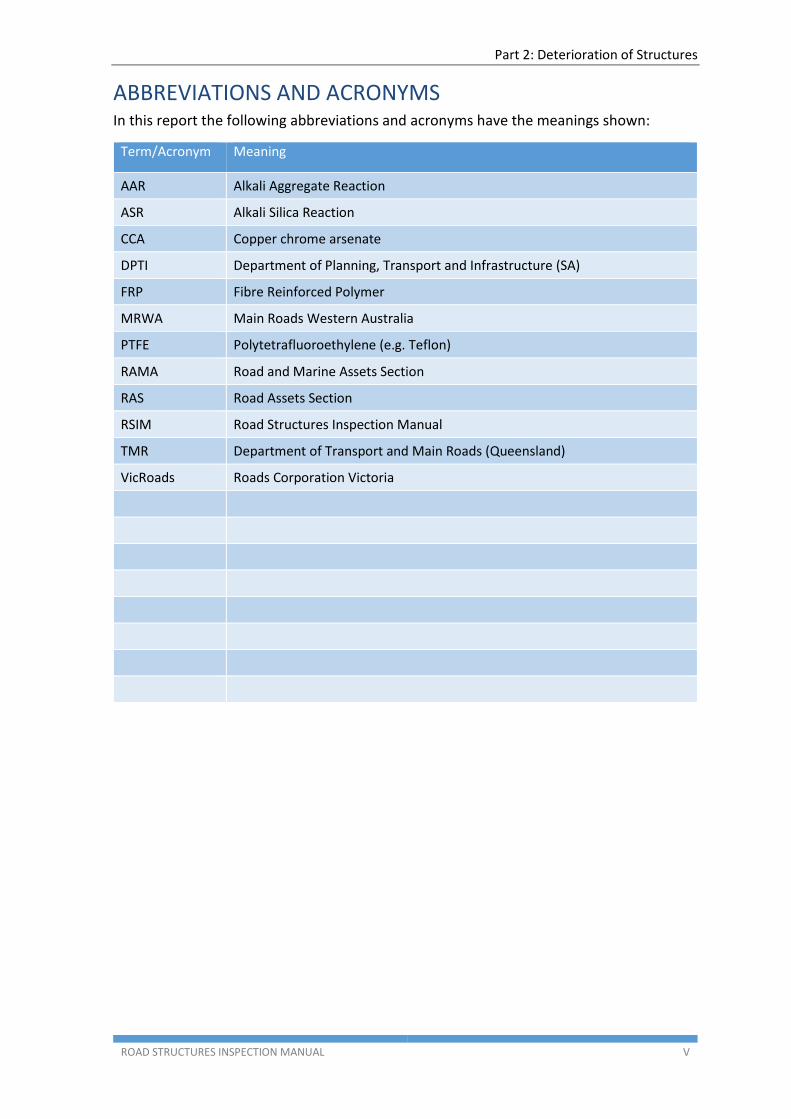
ABBREVIATIONS AND ACRONYMS In this report the following abbreviations and acronyms have the meanings shown:
Term/Acronym Meaning
AAR Alkali Aggregate Reaction
ASR Alkali Silica Reaction
CCA Copper chrome arsenate
DPTI Department of Planning, Transport and Infrastructure (SA)
FRP Fibre Reinforced Polymer
MRWA Main Roads Western Australia
PTFE Polytetrafluoroethylene (e.g. Teflon)
RAMA Road and Marine Assets Section
RAS Road Assets Section
RSIM Road Structures Inspection Manual
TMR Department of Transport and Main Roads (Queensland)
VicRoads Roads Corporation Victoria
Part 2: Deterioration of Structures
ROAD STRUCTURES INSPECTION MANUAL 1
1. MATERIAL DEFECTS
1.1 General
Defects that develop in bridges must be observed, assessed, recorded and reported for importance with respect to their implications regarding safety and durability.
The reporting process must include recommendations for remedial actions that are considered necessary, with an appropriate completion timeframe.
The duties and actions of all bridge inspectors are encapsulated in the foregoing.
When various parts fail to perform in the manner that was originally intended by the designer, then they are classified as defects.
There is a broad spectrum of reasons that cause defective bridge elements and often two or even more can be identified in combinations that lie at the root cause. The reasons are often seemingly minor, and mainly do not threaten the integrity of the structure. However major deficiencies or omissions have been identified in engineering history that has contributed to:-
Serious and expensive outcomes, and
Structural failure when not recognised, discovered or repaired in a timely manner.
It is the intention that regular inspection will:-
Identify and record the presence of defects
Provide cost effective management of defects that ensure:- o Safety for the road user, o An acceptable economic structure life, and
Prevent disastrous outcomes
Defects in bridges arise due to any or all of four major reasons as follows:-
1. Poor design
Includes original design errors or non-compliance with design codes.
2. Poor materials
This can include incorrect or poor original choice of material specified on the drawings
Materials that are used in construction that do not comply with specifications, or
Use of an unsatisfactory alternative during construction (and possibly unapproved) to the specified material.
3. Poor workmanship
This factor can cause a major defect and risk to develop, but mostly affects the durability, whereby earlier than anticipated remedial work has to be carried out. A simple example is premature spalling of concrete due to construction with less clear cover than specified.
Part 2: Deterioration of Structures
ROAD STRUCTURES INSPECTION MANUAL 2
4. Significant events that cause defects developing during life of the structure can include
Scour of foundations that can reduce stability and/or load carrying capacity.
Corrosion of critical steel members.
Cracking and Spalling of concrete.
Unexpected lateral, longitudinal and vertical movement of the structure.
Drainage problems that endanger structural stability.
Significant collision damage to critical elements due to vehicular accidents.
Elements that are suspected of nearing their endurance limit (fatigue).
Vegetation growth – particularly large trees, which can exert immense lateral forces on structures.
Seismic events.
While diagnosis of the causes of defects is not a requirement for a Level 1 or Level 2 inspection, it is of great value for the inspector to have an appreciation of structural behaviour and of the defects that might occur.
Such an appreciation will guide and alert the inspector to particular signs enabling attention to be focussed where it is most needed. This ensures that when a defect is observed, the necessary data is collected on site so that a correct diagnosis can be made, especially when defects occur due to a combination of causes.
Identification of structural defects and their causes require considerable care as structural distress within an element may often have consequential effects on other elements and it may not be immediately apparent which element has caused the failure. For example:
Failure in the bridge foundations, due to settlement, sliding or rotation, is often manifested as cracking, differential movement or other defect in the substructure. Such movements may be displayed as abnormal clearances between the abutment ballast wall and the end of the deck, or as out-of-range movements at the expansion joints or bearings.
Settlement of embankments may affect the substructure, appearing as depressions in the road surface adjacent to the structure or as discontinuities in the kerb line.
Seized or locked bearings can transfer unexpected forces into the bearing shelf resulting in spalling to the front face of the headstock or bearing shelf.
This section describes the defects that are normally found in concrete, steel, timber, masonry and protective coatings and FRP. Each defect is briefly described and the causes producing it are identified.
1.2 Concrete
Concrete is used in structures as plain concrete, such as tremie and mass concrete; or it is combined with conventional steel reinforcement as reinforced concrete, or with prestressing steel reinforcement as prestressed concrete.
Defects in concrete can often be related to the lack of durability of the concrete, resulting from the composition of the concrete, poor placement practices, poor quality control or the aggressive environment in which it is placed.
Part 2: Deterioration of Structures
ROAD STRUCTURES INSPECTION MANUAL 3
The Inspector should refer to the following deterioration checklist items to ensure that the condition of the materials has been reviewed thoroughly as part of the bridge inspection. Special attention also needs to be paid to the condition of any new repairs and strengthening works that may not have previously been reported.
The following defects commonly occur in concrete:
Scaling
Disintegration
Corrosion of reinforcement
Delamination
Spalling
Cracking
Alkali Aggregate Reaction (AAR)
Surface Defects
Fire
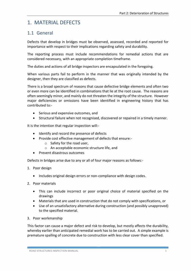
1.2.1 Scaling
Scaling is the gradual and continuous flaking or loss of surface mortar and aggregate over irregular areas to a depth of approximately 5mm. It is prone to occur in poorly finished or overworked concrete where too many fines and not enough entrained air is found near the surface.
Loss of this cement rich layer on the surface may lead to a significant reduction in overall durability of the member.
Scaling is distinguished from spalling (refer Section 1.2.5) due to the difference in concrete depth affected – scaling is rather superficial, whereas spalling extends through the entire cover to the reinforcement (and possibly deeper). It is most commonly found on horizontal surfaces exposed to the weather and to traffic, in splash and tidal zones near the ground line, but can also be present elsewhere.
Figure 1: Concrete scaling
Part 2: Deterioration of Structures
ROAD STRUCTURES INSPECTION MANUAL 4
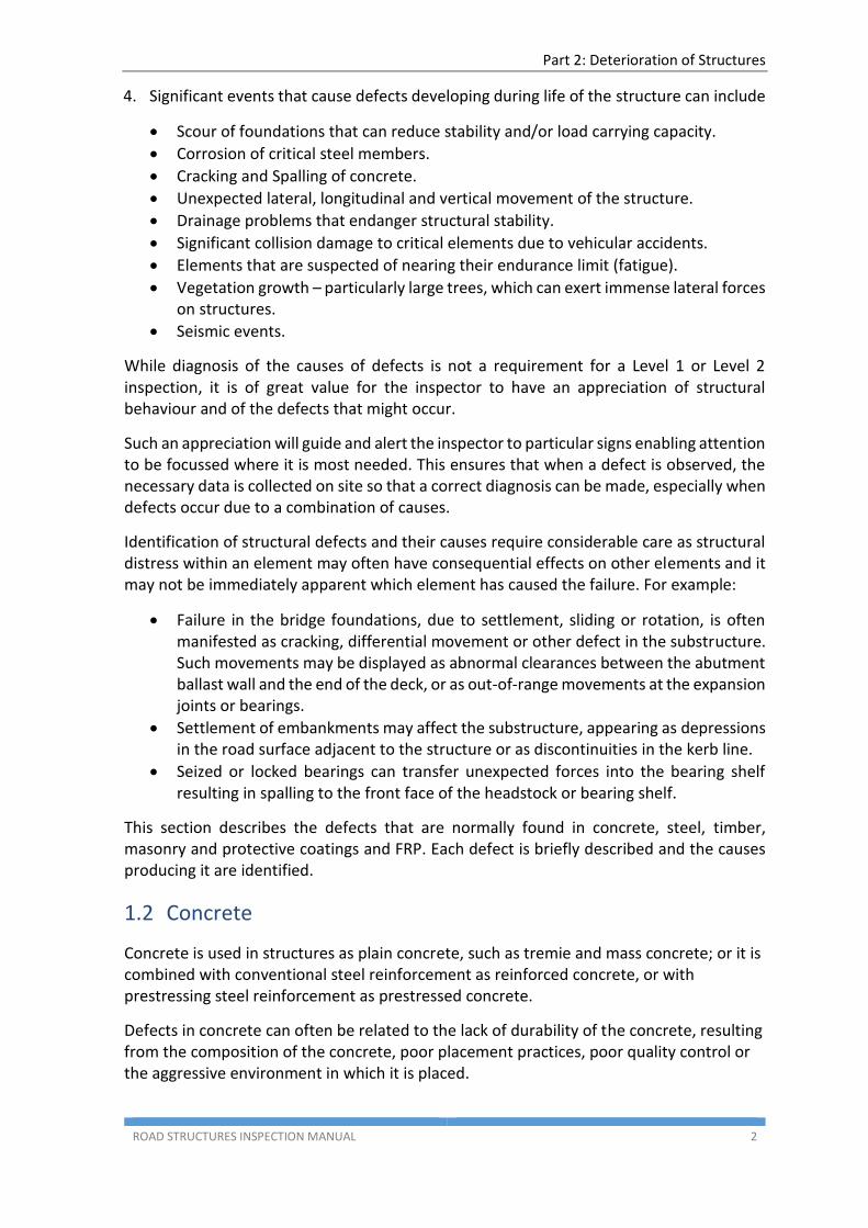
1.2.2 Disintegration
Disintegration is the physical deterioration or breaking down of the concrete into small fragments or particles. The deterioration usually starts in the form of scaling and, if allowed to progress beyond the level of very severe scaling, results in disintegration.
Figure 2: Disintegration of concrete
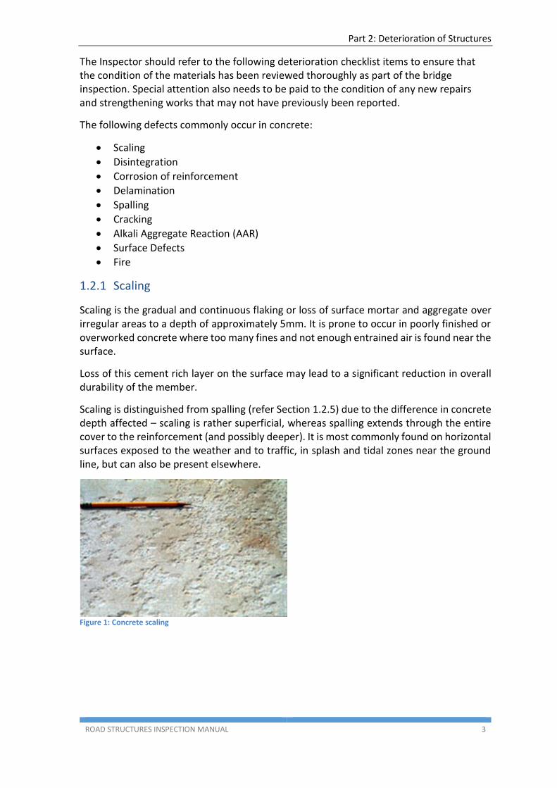
1.2.3 Corrosion of reinforcement
Corrosion is the deterioration of reinforcement by the process of oxidation. Corrosion can also occur in the presence of high Chloride ion concentration such as when the concrete is immersed in sea-water or exposed to salt-spray. Corrosion may appear as a rust stain on the concrete surface initially. In the advanced stages, the surface concrete above the reinforcement can crack, delaminate and spall-off exposing the underlying reinforcement.
Figure 3: Corrosion of reinforcement in concrete
Figure 4: Corrosion of reinforcement in concrete
Part 2: Deterioration of Structures
ROAD STRUCTURES INSPECTION MANUAL 5
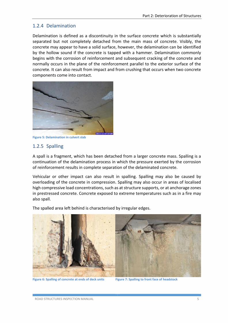
1.2.4 Delamination
Delamination is defined as a discontinuity in the surface concrete which is substantially separated but not completely detached from the main mass of concrete. Visibly, the concrete may appear to have a solid surface, however, the delamination can be identified by the hollow sound if the concrete is tapped with a hammer. Delamination commonly begins with the corrosion of reinforcement and subsequent cracking of the concrete and normally occurs in the plane of the reinforcement parallel to the exterior surface of the concrete. It can also result from impact and from crushing that occurs when two concrete components come into contact.
Figure 5: Delamination in culvert slab
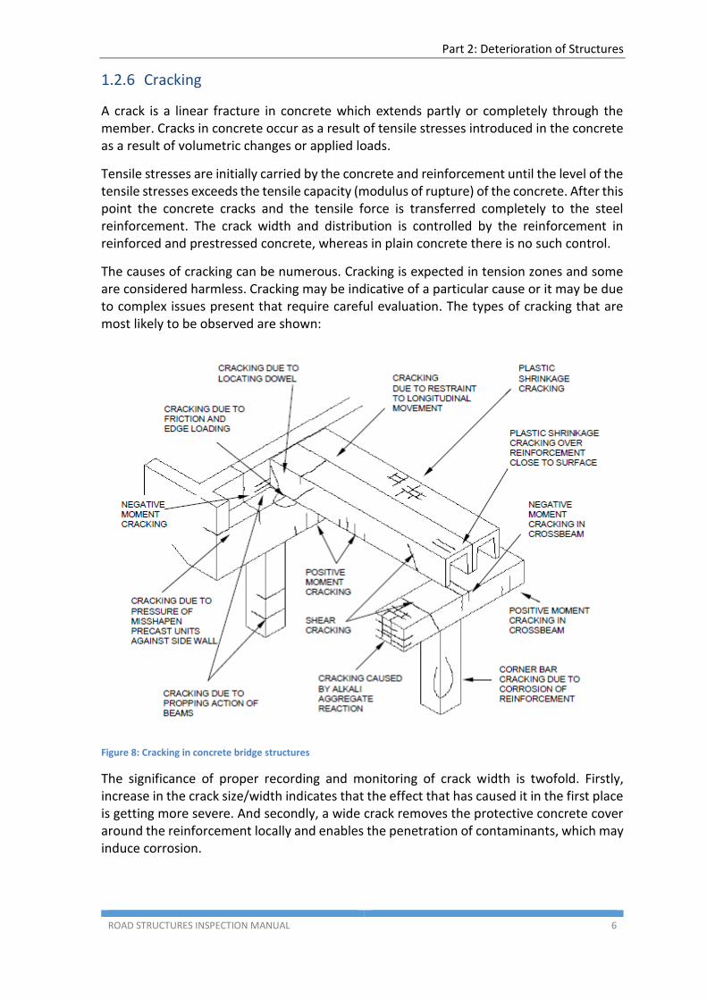
1.2.5 Spalling
A spall is a fragment, which has been detached from a larger concrete mass. Spalling is a continuation of the delamination process in which the pressure exerted by the corrosion of reinforcement results in complete separation of the delaminated concrete.
Vehicular or other impact can also result in spalling. Spalling may also be caused by overloading of the concrete in compression. Spalling may also occur in areas of localised high compressive load concentrations, such as at structure supports, or at anchorage zones in prestressed concrete. Concrete exposed to extreme temperatures such as in a fire may also spall.
The spalled area left behind is characterised by irregular edges.
Figure 6: Spalling of concrete at ends of deck units
Figure 7: Spalling to front face of headstock
Part 2: Deterioration of Structures
ROAD STRUCTURES INSPECTION MANUAL 6
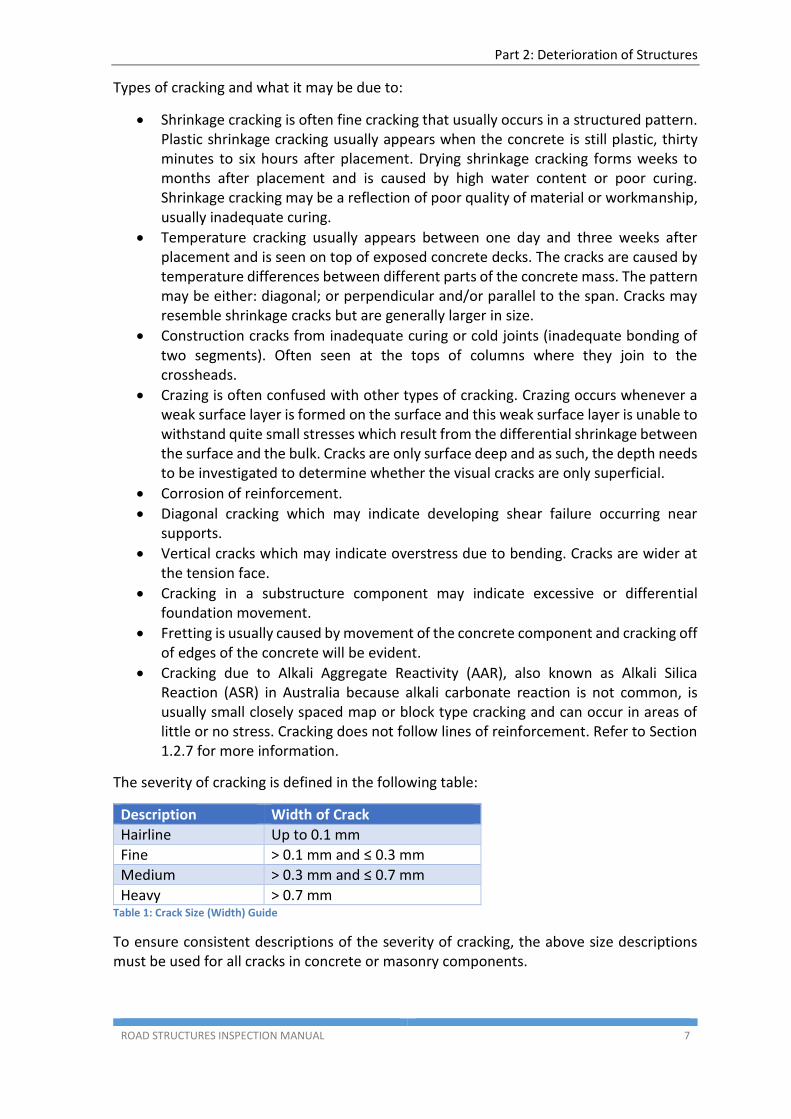
1.2.6 Cracking
A crack is a linear fracture in concrete which extends partly or completely through the member. Cracks in concrete occur as a result of tensile stresses introduced in the concrete as a result of volumetric changes or applied loads.
Tensile stresses are initially carried by the concrete and reinforcement until the level of the tensile stresses exceeds the tensile capacity (modulus of rupture) of the concrete. After this point the concrete cracks and the tensile force is transferred completely to the steel reinforcement. The crack width and distribution is controlled by the reinforcement in reinforced and prestressed concrete, whereas in plain concrete there is no such control.
The causes of cracking can be numerous. Cracking is expected in tension zones and some are considered harmless. Cracking may be indicative of a particular cause or it may be due to complex issues present that require careful evaluation. The types of cracking that are most likely to be observed are shown:
Figure 8: Cracking in concrete bridge structures
The significance of proper recording and monitoring of crack width is twofold. Firstly, increase in the crack size/width indicates that the effect that has caused it in the first place is getting more severe. And secondly, a wide crack removes the protective concrete cover around the reinforcement locally and enables the penetration of contaminants, which may induce corrosion.
Part 2: Deterioration of Structures
ROAD STRUCTURES INSPECTION MANUAL 7
Types of cracking and what it may be due to:
Shrinkage cracking is often fine cracking that usually occurs in a structured pattern. Plastic shrinkage cracking usually appears when the concrete is still plastic, thirty minutes to six hours after placement. Drying shrinkage cracking forms weeks to months after placement and is caused by high water content or poor curing. Shrinkage cracking may be a reflection of poor quality of material or workmanship, usually inadequate curing.
Temperature cracking usually appears between one day and three weeks after placement and is seen on top of exposed concrete decks. The cracks are caused by temperature differences between different parts of the concrete mass. The pattern may be either: diagonal; or perpendicular and/or parallel to the span. Cracks may resemble shrinkage cracks but are generally larger in size.
Construction cracks from inadequate curing or cold joints (inadequate bonding of two segments). Often seen at the tops of columns where they join to the crossheads.
Crazing is often confused with other types of cracking. Crazing occurs whenever a weak surface layer is formed on the surface and this weak surface layer is unable to withstand quite small stresses which result from the differential shrinkage between the surface and the bulk. Cracks are only surface deep and as such, the depth needs to be investigated to determine whether the visual cracks are only superficial.
Corrosion of reinforcement.
Diagonal cracking which may indicate developing shear failure occurring near supports.
Vertical cracks which may indicate overstress due to bending. Cracks are wider at the tension face.
Cracking in a substructure component may indicate excessive or differential foundation movement.
Fretting is usually caused by movement of the concrete component and cracking off of edges of the concrete will be evident.
Cracking due to Alkali Aggregate Reactivity (AAR), also known as Alkali Silica Reaction (ASR) in Australia because alkali carbonate reaction is not common, is usually small closely spaced map or block type cracking and can occur in areas of little or no stress. Cracking does not follow lines of reinforcement. Refer to Section 1.2.7 for more information.
The severity of cracking is defined in the following table:
Description Width of Crack
Hairline Up to 0.1 mm
Fine > 0.1 mm and ≤ 0.3 mm
Medium > 0.3 mm and ≤ 0.7 mm
Heavy > 0.7 mm Table 1: Crack Size (Width) Guide
To ensure consistent descriptions of the severity of cracking, the above size descriptions must be used for all cracks in concrete or masonry components.
Part 2: Deterioration of Structures
ROAD STRUCTURES INSPECTION MANUAL 8
When the concrete surface around a crack has spalled, it is important to ensure that the actual crack width is measured rather than the spalled width as shown:
Figure 9: Accurate measurement of crack width
1.2.7 Alkali Aggregate Reaction (AAR)
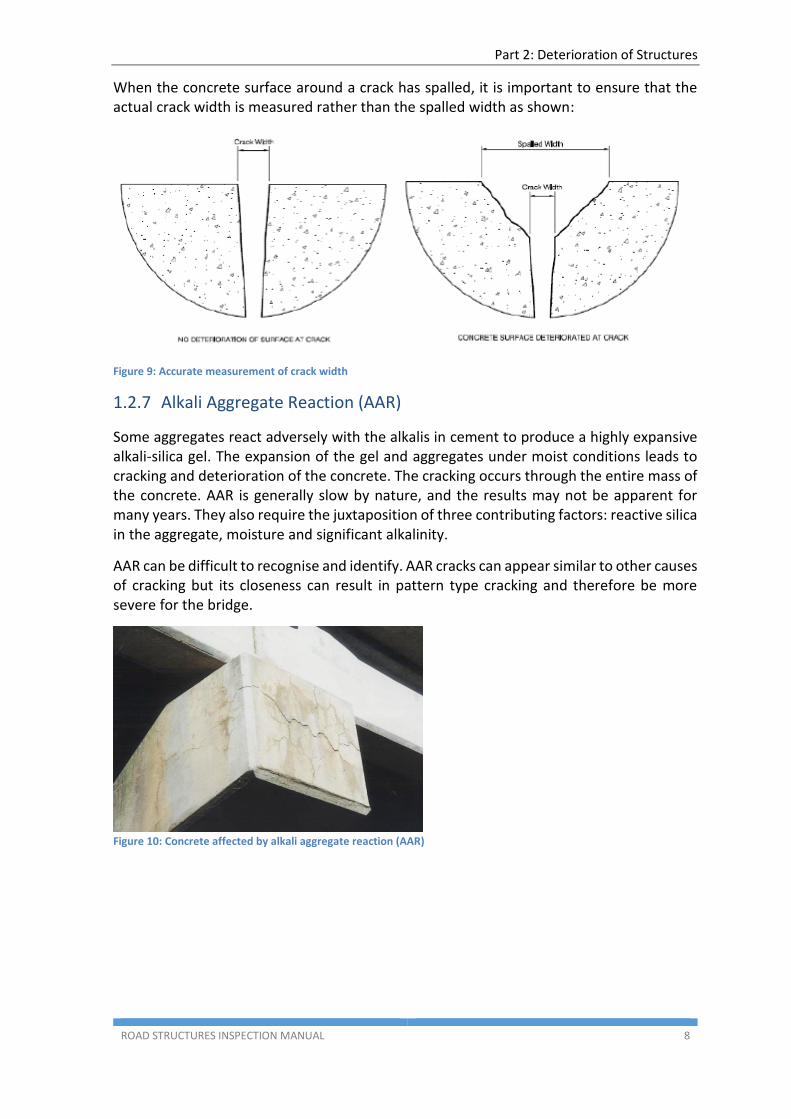
Some aggregates react adversely with the alkalis in cement to produce a highly expansive alkali-silica gel. The expansion of the gel and aggregates under moist conditions leads to cracking and deterioration of the concrete. The cracking occurs through the entire mass of the concrete. AAR is generally slow by nature, and the results may not be apparent for many years. They also require the juxtaposition of three contributing factors: reactive silica in the aggregate, moisture and significant alkalinity.
AAR can be difficult to recognise and identify. AAR cracks can appear similar to other causes of cracking but its closeness can result in pattern type cracking and therefore be more severe for the bridge.
Figure 10: Concrete affected by alkali aggregate reaction (AAR)
Part 2: Deterioration of Structures
ROAD STRUCTURES INSPECTION MANUAL 9
1.2.8 Surface Defects
The following are examples of surface defects in concrete:
Segregation
Cold Joints
Surface deposits -efflorescence, stalactite
Honeycombing
Abrasion
Erosion
Surface defects are not necessarily serious. However, they can be indicative of a potential weakness in the concrete.
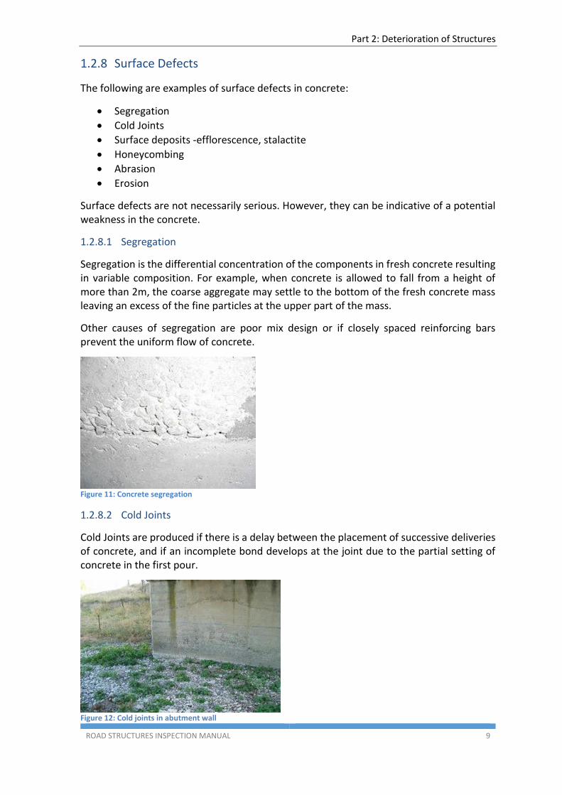
1.2.8.1 Segregation
Segregation is the differential concentration of the components in fresh concrete resulting in variable composition. For example, when concrete is allowed to fall from a height of more than 2m, the coarse aggregate may settle to the bottom of the fresh concrete mass leaving an excess of the fine particles at the upper part of the mass.
Other causes of segregation are poor mix design or if closely spaced reinforcing bars prevent the uniform flow of concrete.
Figure 11: Concrete segregation
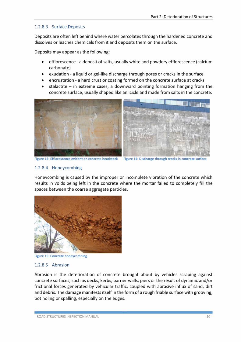
1.2.8.2 Cold Joints
Cold Joints are produced if there is a delay between the placement of successive deliveries of concrete, and if an incomplete bond develops at the joint due to the partial setting of concrete in the first pour.
Figure 12: Cold joints in abutment wall
Part 2: Deterioration of Structures
ROAD STRUCTURES INSPECTION MANUAL 10
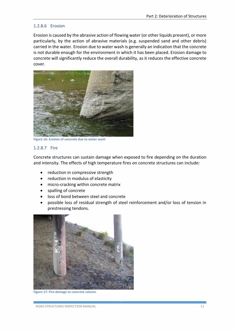
1.2.8.3 Surface Deposits
Deposits are often left behind where water percolates through the hardened concrete and dissolves or leaches chemicals from it and deposits them on the surface.
Deposits may appear as the following:
efflorescence - a deposit of salts, usually white and powdery efflorescence (calcium carbonate)
exudation - a liquid or gel-like discharge through pores or cracks in the surface
encrustation - a hard crust or coating formed on the concrete surface at cracks
stalactite – in extreme cases, a downward pointing formation hanging from the concrete surface, usually shaped like an icicle and made from salts in the concrete.
Figure 13: Efflorescence evident on concrete headstock
Figure 14: Discharge through cracks in concrete surface
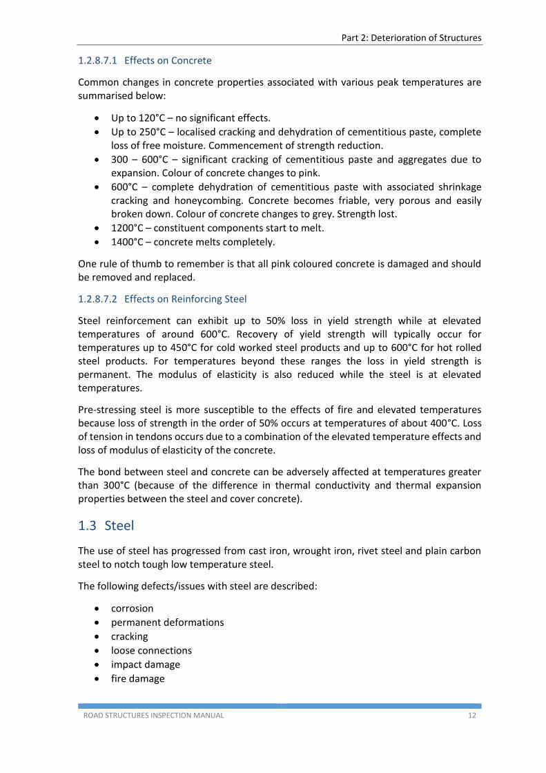
1.2.8.4 Honeycombing
Honeycombing is caused by the improper or incomplete vibration of the concrete which results in voids being left in the concrete where the mortar failed to completely fill the spaces between the coarse aggregate particles.
Figure 15: Concrete honeycombing
1.2.8.5 Abrasion
Abrasion is the deterioration of concrete brought about by vehicles scraping against concrete surfaces, such as decks, kerbs, barrier walls, piers or the result of dynamic and/or frictional forces generated by vehicular traffic, coupled with abrasive influx of sand, dirt and debris. The damage manifests itself in the form of a rough friable surface with grooving, pot holing or spalling, especially on the edges.
Part 2: Deterioration of Structures
ROAD STRUCTURES INSPECTION MANUAL 11
1.2.8.6 Erosion
Erosion is caused by the abrasive action of flowing water (or other liquids present), or more particularly, by the action of abrasive materials (e.g. suspended sand and other debris) carried in the water. Erosion due to water wash is generally an indication that the concrete is not durable enough for the environment in which it has been placed. Erosion damage to concrete will significantly reduce the overall durability, as it reduces the effective concrete cover.
Figure 16: Erosion of concrete due to water wash
1.2.8.7 Fire
Concrete structures can sustain damage when exposed to fire depending on the duration and intensity. The effects of high temperature fires on concrete structures can include:
reduction in compressive strength
reduction in modulus of elasticity
micro-cracking within concrete matrix
spalling of concrete
loss of bond between steel and concrete
possible loss of residual strength of steel reinforcement and/or loss of tension in prestressing tendons.
Figure 17: Fire damage to concrete column
Part 2: Deterioration of Structures
ROAD STRUCTURES INSPECTION MANUAL 12
1.2.8.7.1 Effects on Concrete
Common changes in concrete properties associated with various peak temperatures are summarised below:
Up to 120°C – no significant effects.
Up to 250°C – localised cracking and dehydration of cementitious paste, complete loss of free moisture. Commencement of strength reduction.
300 – 600°C – significant cracking of cementitious paste and aggregates due to expansion. Colour of concrete changes to pink.
600°C – complete dehydration of cementitious paste with associated shrinkage cracking and honeycombing. Concrete becomes friable, very porous and easily broken down. Colour of concrete changes to grey. Strength lost.
1200°C – constituent components start to melt.
1400°C – concrete melts completely.
One rule of thumb to remember is that all pink coloured concrete is damaged and should be removed and replaced.
1.2.8.7.2 Effects on Reinforcing Steel
Steel reinforcement can exhibit up to 50% loss in yield strength while at elevated temperatures of around 600°C. Recovery of yield strength will typically occur for temperatures up to 450°C for cold worked steel products and up to 600°C for hot rolled steel products. For temperatures beyond these ranges the loss in yield strength is permanent. The modulus of elasticity is also reduced while the steel is at elevated temperatures.
Pre-stressing steel is more susceptible to the effects of fire and elevated temperatures because loss of strength in the order of 50% occurs at temperatures of about 400°C. Loss of tension in tendons occurs due to a combination of the elevated temperature effects and loss of modulus of elasticity of the concrete.
The bond between steel and concrete can be adversely affected at temperatures greater than 300°C (because of the difference in thermal conductivity and thermal expansion properties between the steel and cover concrete).
1.3 Steel
The use of steel has progressed from cast iron, wrought iron, rivet steel and plain carbon steel to notch tough low temperature steel.
The following defects/issues with steel are described:
corrosion
permanent deformations
cracking
loose connections
impact damage
fire damage
Part 2: Deterioration of Structures
ROAD STRUCTURES INSPECTION MANUAL 13
1.3.1 Corrosion
Corrosion (rust) is the oxidation of steel resulting from exposure to air, moisture, fumes, chemicals and contact with other metals. Corrosion can be prevented or minimised by the use of coatings but the effectiveness of these coatings is reduced or lost if the coating is damaged.
Rust on carbon steel is initially fine grained, but as rusting progresses it becomes flaky and delaminates, exposing a pitted surface leading to a progressive loss of section.
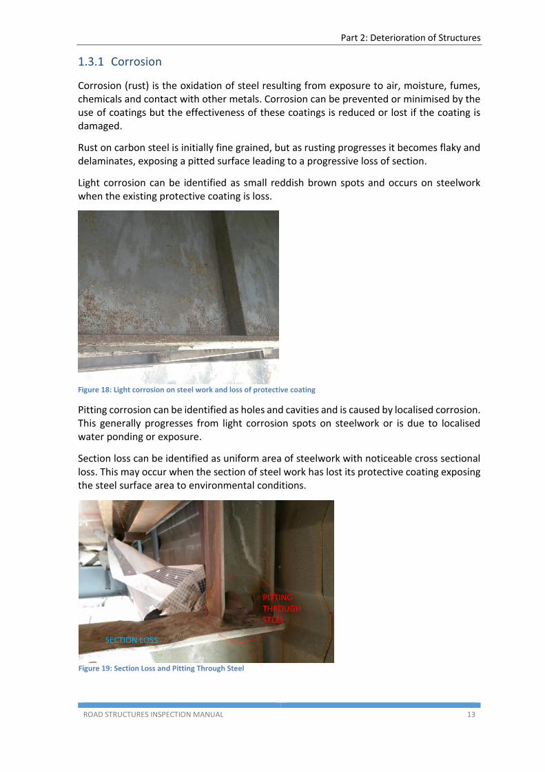
Light corrosion can be identified as small reddish brown spots and occurs on steelwork when the existing protective coating is loss.
Figure 18: Light corrosion on steel work and loss of protective coating
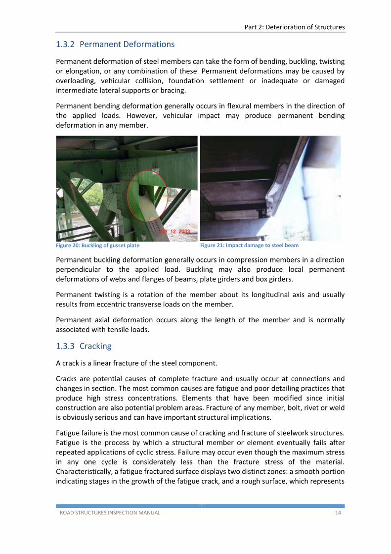
Pitting corrosion can be identified as holes and cavities and is caused by localised corrosion. This generally progresses from light corrosion spots on steelwork or is due to localised water ponding or exposure.
Section loss can be identified as uniform area of steelwork with noticeable cross sectional loss. This may occur when the section of steel work has lost its protective coating exposing the steel surface area to environmental conditions.
Figure 19: Section Loss and Pitting Through Steel
PITTING THROUGH STEEL
SECTION LOSS
Part 2: Deterioration of Structures
ROAD STRUCTURES INSPECTION MANUAL 14
1.3.2 Permanent Deformations
Permanent deformation of steel members can take the form of bending, buckling, twisting or elongation, or any combination of these. Permanent deformations may be caused by overloading, vehicular collision, foundation settlement or inadequate or damaged intermediate lateral supports or bracing.
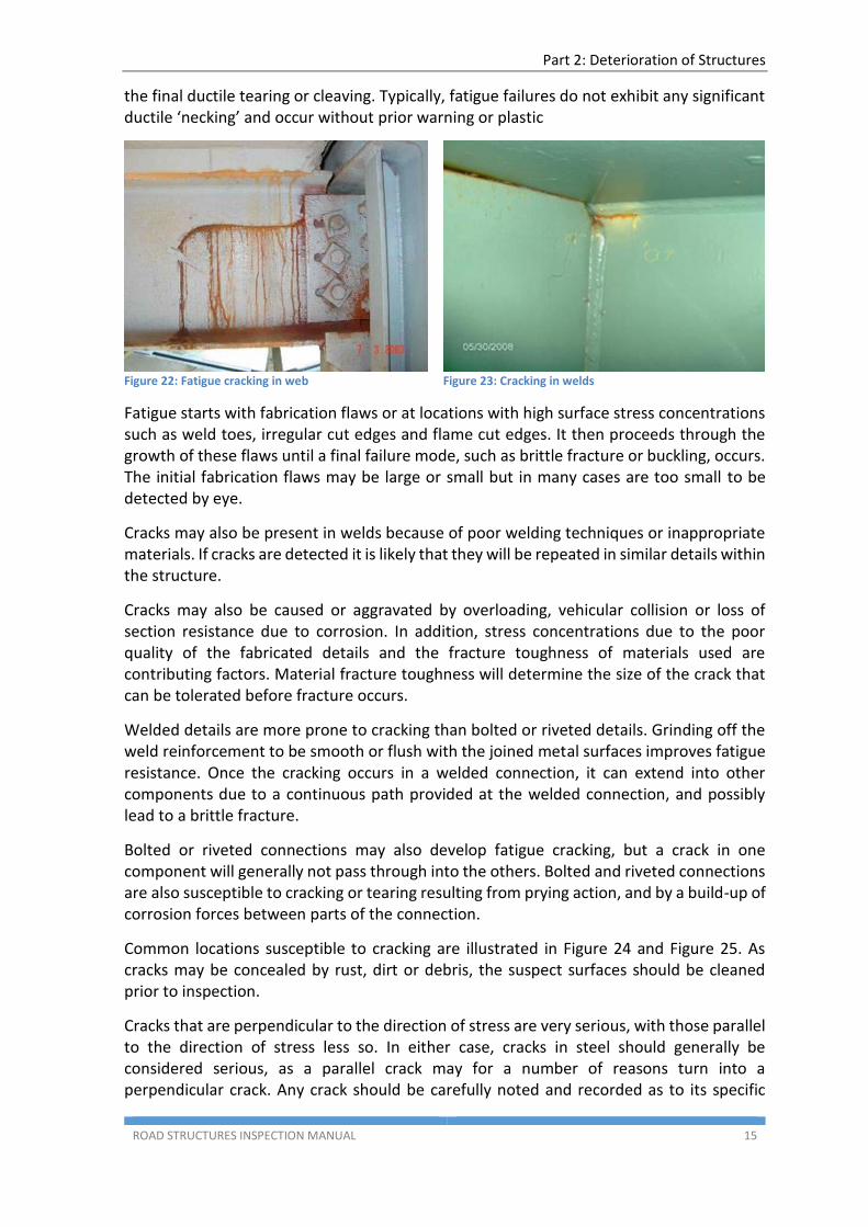
Permanent bending deformation generally occurs in flexural members in the direction of the applied loads. However, vehicular impact may produce permanent bending deformation in any member.
Figure 20: Buckling of gusset plate
Figure 21: Impact damage to steel beam
Permanent buckling deformation generally occurs in compression members in a direction perpendicular to the applied load. Buckling may also produce local permanent deformations of webs and flanges of beams, plate girders and box girders.
Permanent twisting is a rotation of the member about its longitudinal axis and usually results from eccentric transverse loads on the member.
Permanent axial deformation occurs along the length of the member and is normally associated with tensile loads.
1.3.3 Cracking
A crack is a linear fracture of the steel component.
Cracks are potential causes of complete fracture and usually occur at connections and changes in section. The most common causes are fatigue and poor detailing practices that produce high stress concentrations. Elements that have been modified since initial construction are also potential problem areas. Fracture of any member, bolt, rivet or weld is obviously serious and can have important structural implications.
Fatigue failure is the most common cause of cracking and fracture of steelwork structures. Fatigue is the process by which a structural member or element eventually fails after repeated applications of cyclic stress. Failure may occur even though the maximum stress in any one cycle is considerately less than the fracture stress of the material. Characteristically, a fatigue fractured surface displays two distinct zones: a smooth portion indicating stages in the growth of the fatigue crack, and a rough surface, which represents
Part 2: Deterioration of Structures
ROAD STRUCTURES INSPECTION MANUAL 15
the final ductile tearing or cleaving. Typically, fatigue failures do not exhibit any significant ductile ‘necking’ and occur without prior warning or plastic
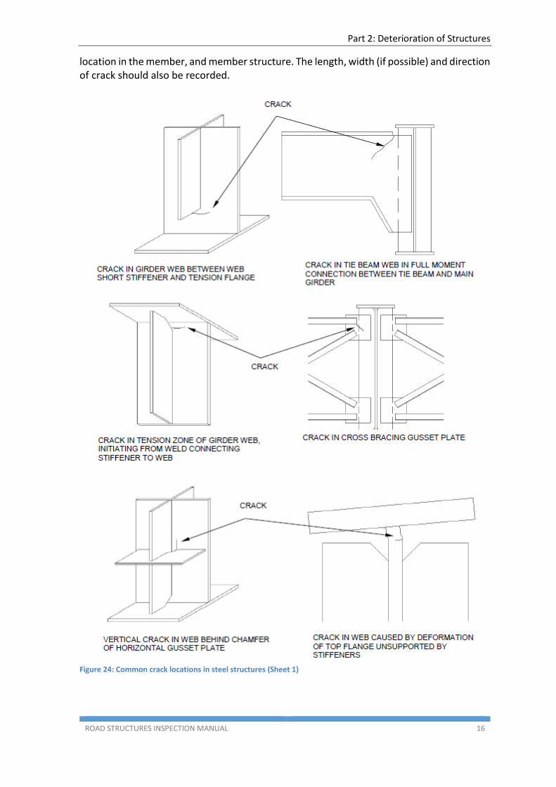
Figure 22: Fatigue cracking in web
Figure 23: Cracking in welds
Fatigue starts with fabrication flaws or at locations with high surface stress concentrations such as weld toes, irregular cut edges and flame cut edges. It then proceeds through the growth of these flaws until a final failure mode, such as brittle fracture or buckling, occurs. The initial fabrication flaws may be large or small but in many cases are too small to be detected by eye.
Cracks may also be present in welds because of poor welding techniques or inappropriate materials. If cracks are detected it is likely that they will be repeated in similar details within the structure.
Cracks may also be caused or aggravated by overloading, vehicular collision or loss of section resistance due to corrosion. In addition, stress concentrations due to the poor quality of the fabricated details and the fracture toughness of materials used are contributing factors. Material fracture toughness will determine the size of the crack that can be tolerated before fracture occurs.
Welded details are more prone to cracking than bolted or riveted details. Grinding off the weld reinforcement to be smooth or flush with the joined metal surfaces improves fatigue resistance. Once the cracking occurs in a welded connection, it can extend into other components due to a continuous path provided at the welded connection, and possibly lead to a brittle fracture.
Bolted or riveted connections may also develop fatigue cracking, but a crack in one component will generally not pass through into the others. Bolted and riveted connections are also susceptible to cracking or tearing resulting from prying action, and by a build-up of corrosion forces between parts of the connection.
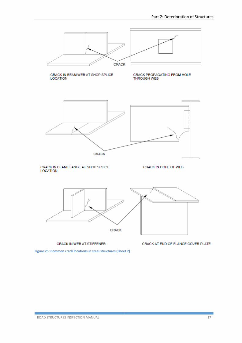
Common locations susceptible to cracking are illustrated in Figure 24 and Figure 25. As cracks may be concealed by rust, dirt or debris, the suspect surfaces should be cleaned prior to inspection.
Cracks that are perpendicular to the direction of stress are very serious, with those parallel to the direction of stress less so. In either case, cracks in steel should generally be considered serious, as a parallel crack may for a number of reasons turn into a perpendicular crack. Any crack should be carefully noted and recorded as to its specific
Part 2: Deterioration of Structures
ROAD STRUCTURES INSPECTION MANUAL 16
location in the member, and member structure. The length, width (if possible) and direction of crack should also be recorded.
Figure 24: Common crack locations in steel structures (Sheet 1)
Part 2: Deterioration of Structures
ROAD STRUCTURES INSPECTION MANUAL 17
Figure 25: Common crack locations in steel structures (Sheet 2)
Part 2: Deterioration of Structures
ROAD STRUCTURES INSPECTION MANUAL 18
1.3.4 Loose Connections
Bolted and riveted connections may become loose as a result of corrosion of the connector plates or fasteners, excessive vibration, overstressing, cracking, or the failure of individual fasteners. Loose connections may sometimes be undetectable by visual inspection. Cracking or excessive corrosion of the connector plates or fasteners, or permanent deformation of the connection or members framing into it, may be indications of a loose connection. Tapping the connection with a hammer is one method of determining if the connection is loose.
1.3.5 Impact Damage
Impact damage to a steel structure is usually obvious and will vary in significance from abrasion of the protective coating through to deformation of a component. In severe cases the load carrying capacity of a component may be compromised.
1.3.6 Fire Damage
Steel progressively weakens with increasing temperature, e.g. the yield strength at room temperature is reduced by about 50% at 550°C, and to about 10% at 1000°C. There is therefore a risk that steel members may fail by buckling or deflecting if they are inadvertently heated during a traffic accident fire. The extent of failure will depend on the loading that the member is carrying, its support conditions, and the temperature gradient through the cross section.
Secondary effect damage can occur in bearings, movement joints and other structural members if they are unable to accommodate the large expansions that may occur in a fire. It is unlikely that this will have been allowed for in design.
In a severe fire unprotected steelwork will lose practically all its load bearing capacity, deform and distort and will not be suitable for reuse. In a less severe fire, damage may be limited and it may be possible to retain members after checking for straightness and distortion and the mechanical properties. Bolted connections often fail through shear or tensile failure or thread stripping. Any section yielding could have caused severe weakening of connections and it is important that these are properly inspected.
Fire will also cause blistering and flaking of paintwork.
Part 2: Deterioration of Structures
ROAD STRUCTURES INSPECTION MANUAL 19
1.4 Masonry
Masonry is made of natural stone blocks or clay bricks usually bonded together by mortar. Although not a common construction material today, masonry was used in retaining walls, abutments, piers or arches, primarily in the 19th century while brick masonry was only rarely used in highway structures. Types of masonry construction are Ashlar masonry, squared stones masonry and rubble masonry.
The following defects commonly occur in masonry:
Cracking
Splitting, spalling and disintegration
Loss of mortar and stones
Arch stones dropping
Side wall movement at masonry arch
Deformation
Separation of arch rings
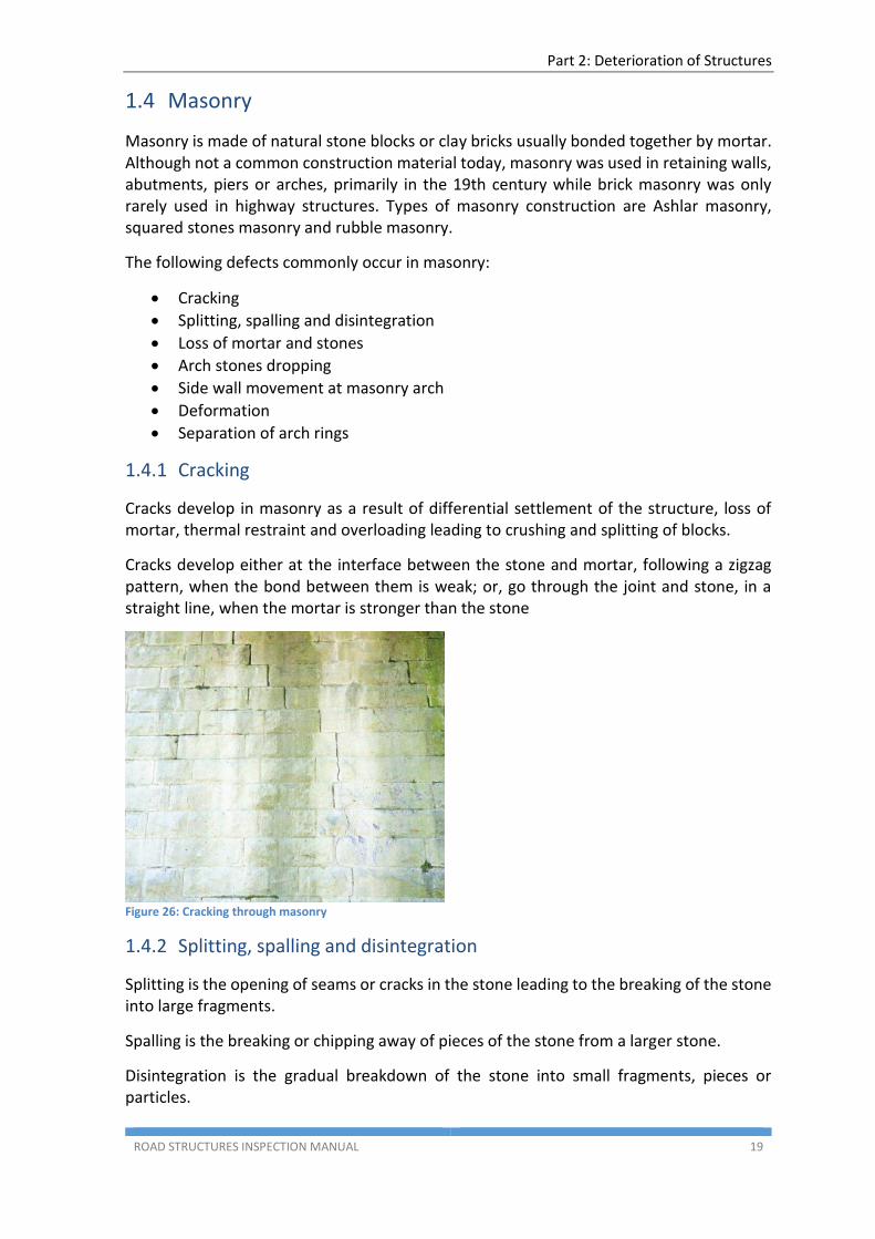
1.4.1 Cracking
Cracks develop in masonry as a result of differential settlement of the structure, loss of mortar, thermal restraint and overloading leading to crushing and splitting of blocks.
Cracks develop either at the interface between the stone and mortar, following a zigzag pattern, when the bond between them is weak; or, go through the joint and stone, in a straight line, when the mortar is stronger than the stone
Figure 26: Cracking through masonry
1.4.2 Splitting, spalling and disintegration
Splitting is the opening of seams or cracks in the stone leading to the breaking of the stone into large fragments.
Spalling is the breaking or chipping away of pieces of the stone from a larger stone.
Disintegration is the gradual breakdown of the stone into small fragments, pieces or particles.
Part 2: Deterioration of Structures
ROAD STRUCTURES INSPECTION MANUAL 20
The splitting, spalling and disintegration of masonry is caused by the actions of weathering and abrasion or by the actions of acids, sulphates or chlorides, which cause deterioration in certain types of stones, such as limestone. Splitting, spalling and disintegration may also occur if adjacent blocks touch as a result of deformation of the arch ring.
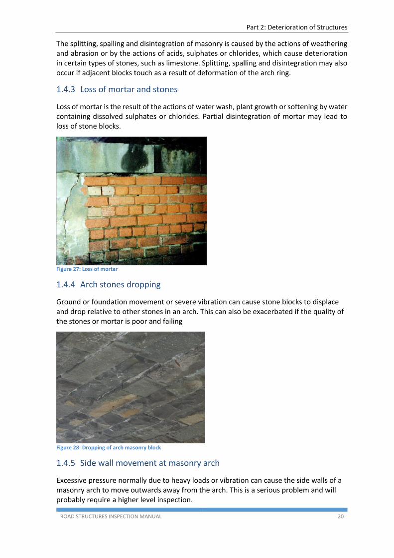
1.4.3 Loss of mortar and stones
Loss of mortar is the result of the actions of water wash, plant growth or softening by water containing dissolved sulphates or chlorides. Partial disintegration of mortar may lead to loss of stone blocks.
Figure 27: Loss of mortar
1.4.4 Arch stones dropping
Ground or foundation movement or severe vibration can cause stone blocks to displace and drop relative to other stones in an arch. This can also be exacerbated if the quality of the stones or mortar is poor and failing
Figure 28: Dropping of arch masonry block
1.4.5 Side wall movement at masonry arch
Excessive pressure normally due to heavy loads or vibration can cause the side walls of a masonry arch to move outwards away from the arch. This is a serious problem and will probably require a higher level inspection.
Part 2: Deterioration of Structures
ROAD STRUCTURES INSPECTION MANUAL 21
1.4.6 Deformation
Arches are either semi-circular, segmental (i.e. part of a semi-circle) or elliptical in shape. The regular curvature may become deformed if the arch is overloaded or if there is differential settlement of the foundations. Deformation may be accompanied by cracking and dropped stones. The position and degree of deformation should be recorded.
1.4.7 Separation of arch rings
Arches may comprise multiple rings or layers of bricks which combine in practice to form a single arch. The rings may delaminate if the mortar fails or if overloading or settlement occurs. The position and degree of separation should be recorded.
1.5 Timber
Timber bridges were not in common use in South Australia. There are no timber bridges remaining on the State Road Network. Any remaining timber bridges are on local roads controlled by Councils. However some structures continue to have timber components (primarily decking).
The following defects commonly occur in timber bridge components:
Fungal rot
Termites
Marine organisms
Corrosion of fasteners
Shrinkage and splitting
Fire damage
Flood damage
Weathering
This section is based on Austroads 1991 Bridge Management Practice.
1.5.1 Fungal Rot
White rot or brown rot fungi causes severe internal decay of bridge timbers members. External surface decay, especially in ground contact areas, is caused by soft rot fungi. Other fungi such as mould and sap stain fungi may produce superficial discolouration on timbers but are not generally of structural significance. Fungal growth does not occur unless there is a source of infection from which the fungus can grow. Fungi procreate by producing vast numbers of microscopic spores which will not germinate and develop unless there is:
An adequate supply of food (wood cells)
An adequate supply of oxygen (air) -prolonged immersion in water saturates timber and inhibits fungal growth
A suitable range of temperatures -optimum temperatures are 20°-25°C for soft rots, while their rate of growth declines above or below the optimum with a greater tolerance of lower temperatures apparent); and
Part 2: Deterioration of Structures
ROAD STRUCTURES INSPECTION MANUAL 22
a continuing supply of moisture (wood with a moisture content below 20 % is safe from decay, and many fungi require a moisture content above 30%)
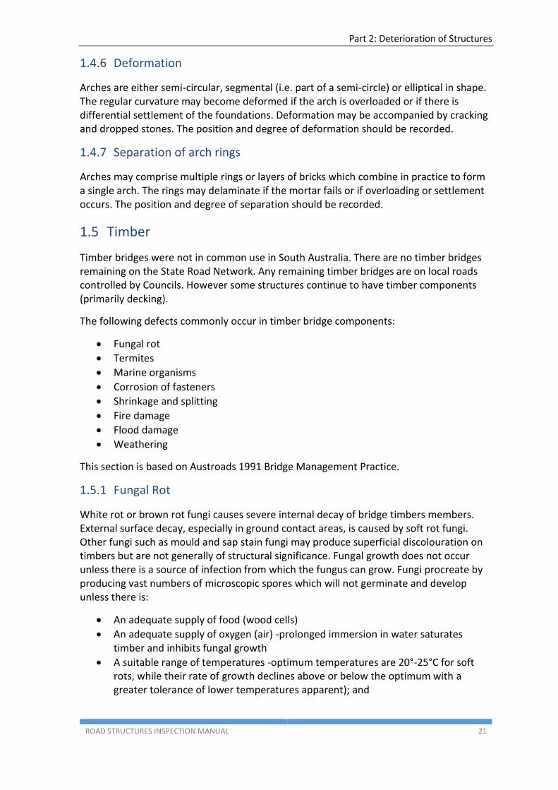
Once established and provided that favourable conditions prevail, the decay fungi continue to grow at an accelerating rate. Depriving the fungi of any one of the required conditions will effectively curtail the spread of decay. Wood that is kept dry or saturated will not rot. Moisture change can affect decay indirectly because drying often leads to surface checks, which may expose untreated parts of timber or create water trapping pockets. Proper preservative treatment effectively provides a toxic barrier to the fungi’s food supply, thus preventing decay.
Figure 29: Fungal fruiting body and decay of girder
Figure 30: Decay pocket in girder
The most common rotting areas in timber bridges are internally in log girders, corbels, headstocks and piles (piping), and in sawn decking at the exposed ends and interface with kerbs. Decay is often more pronounced at the ends of members.
1.5.2 Termites
Australia has a large number of termite species which are widely distributed. Heavy termite attack is found in the northern tropical belt of Australia but the hazard is sufficient in southern Australia to constitute a significant problem. Practically all termite damage to timber bridges occurs through subterranean termites (especially Coptotermes acinaciformis and allied species) which require contact with the soil or some other constant source of moisture.
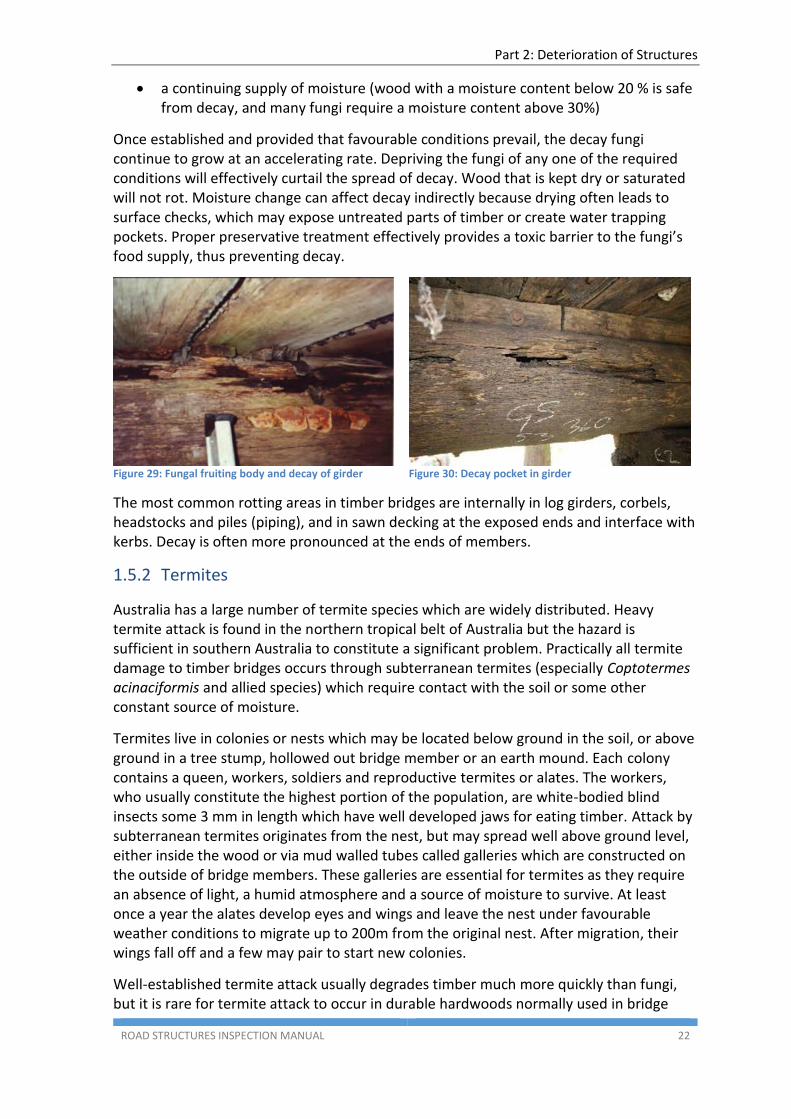
Termites live in colonies or nests which may be located below ground in the soil, or above ground in a tree stump, hollowed out bridge member or an earth mound. Each colony contains a queen, workers, soldiers and reproductive termites or alates. The workers, who usually constitute the highest portion of the population, are white-bodied blind insects some 3 mm in length which have well developed jaws for eating timber. Attack by subterranean termites originates from the nest, but may spread well above ground level, either inside the wood or via mud walled tubes called galleries which are constructed on the outside of bridge members. These galleries are essential for termites as they require an absence of light, a humid atmosphere and a source of moisture to survive. At least once a year the alates develop eyes and wings and leave the nest under favourable weather conditions to migrate up to 200m from the original nest. After migration, their wings fall off and a few may pair to start new colonies.
Well-established termite attack usually degrades timber much more quickly than fungi, but it is rare for termite attack to occur in durable hardwoods normally used in bridge
Part 2: Deterioration of Structures
ROAD STRUCTURES INSPECTION MANUAL 23
construction without some pre-existing fungal decay. This decay accelerates as the termites extend their galleries through the structure, moving fungal spores and moisture about with their bodies. Hence, although most of the material removed by termites has already lost its structural strength because of decay, the control of termites remains an important consideration.
Figure 31: Termite attack
Basically, there are two main strategies in termite control:
Eradication of the nest (by either direct chemical treatment or by separation of the colony from its sustaining moisture)
Installation of chemical and physical barriers to prevent termites from entering a bridge or attacking timber in contact with the ground
In practice it may be difficult to eradicate the nest because of the problem of locating it.
1.5.3 Marine Organisms
Damage to underwater timber in the sea or tidal inlets is usually caused by marine borers, and is more severe in tropical and sub-tropical waters than in colder waters.
The two main groups of animal involved are:
molluscs (teredinidae) -this group includes various species of Teredo, Nausitora and Bankia.
crustaceans -this group includes species of Sphaeroma (pill bugs), Limnoria (gribbles), and Chelura.
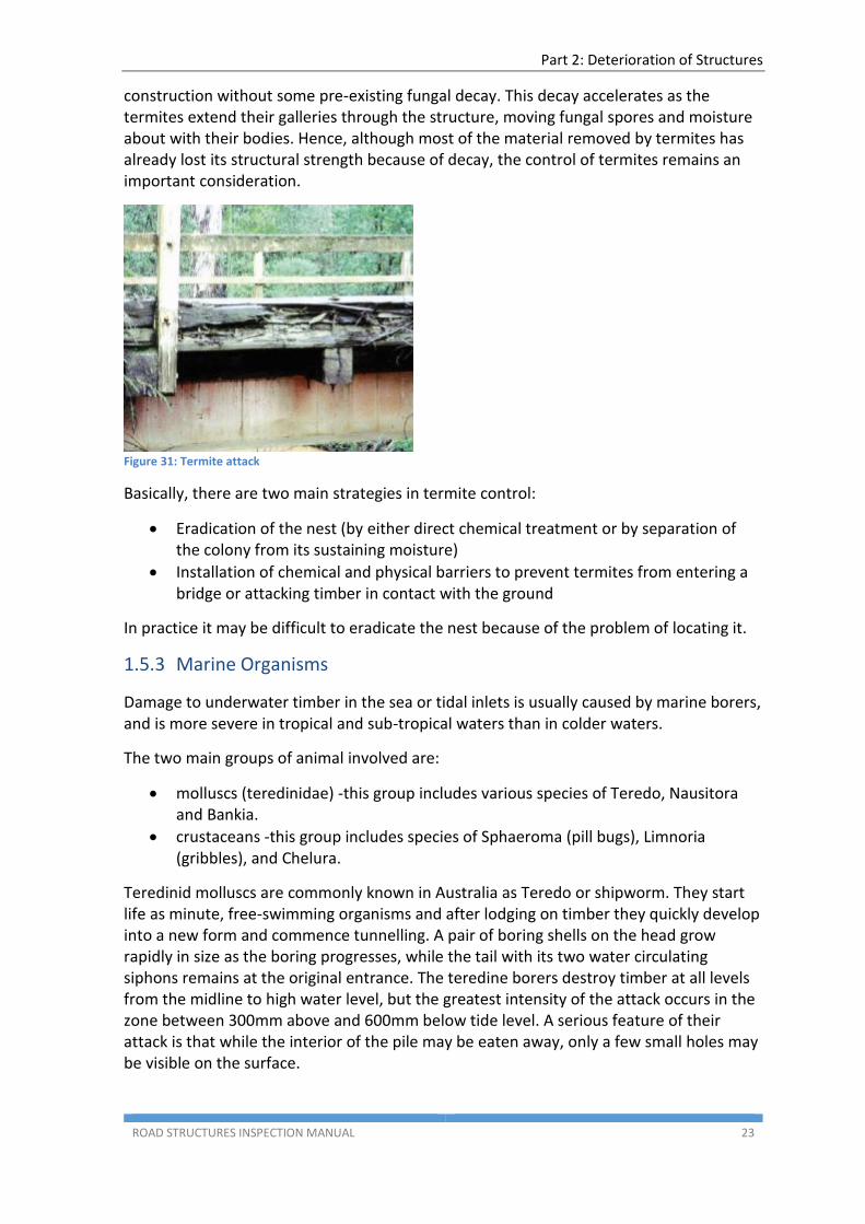
Teredinid molluscs are commonly known in Australia as Teredo or shipworm. They start life as minute, free-swimming organisms and after lodging on timber they quickly develop into a new form and commence tunnelling. A pair of boring shells on the head grow rapidly in size as the boring progresses, while the tail with its two water circulating siphons remains at the original entrance. The teredine borers destroy timber at all levels from the midline to high water level, but the greatest intensity of the attack occurs in the zone between 300mm above and 600mm below tide level. A serious feature of their attack is that while the interior of the pile may be eaten away, only a few small holes may be visible on the surface.
Part 2: Deterioration of Structures
ROAD STRUCTURES INSPECTION MANUAL 24
Figure 32: Signs of teredinid marine borer
Crustaceans attack the wood on its surface, making many narrower and shorter tunnels than those made by the teredines. The timber so affected is steadily eroded from the outside by wave action and the piles assume a wasted appearance or hourglass effect. Attack by Sphaeroma is limited to the zone between tidal limits, with the greatest damage close to half tide level. They cannot survive in water containing less than 1.0 -1.5 per cent salinity, but can grow at lower temperatures than the teredines.
Many strategies have been developed for the control of marine borers but, assuming that the piles have sufficient remaining strength, the most effective work by reducing the oxygen content of water around the borers.
1.5.4 Corrosion of Fasteners
Corrosion of steel fasteners can cause serious strength reductions for two related reasons. Firstly, the steel fastener reduces in size and weakens, and secondly a chemical reaction involving iron salts from the rusting process can significantly reduce the strength of the surrounding wood (this is not fungal decay but may enhance corrosion of the fastener because of water ingress in the softened timber).
Galvanised fasteners in contact with timber which has been freshly treated with CCA preservative may exhibit enhanced corrosion. However, for CCA treated timber that has been cured for six weeks, normal corrosion rates for fasteners will apply.
1.5.5 Shrinkage and Splitting
Moisture can exist in wood as water or water vapour in the cell cavities and as chemically bound water within the cell walls. As green timber losses moisture to the surrounding atmosphere, a point is reached when the cell cavities no longer contain moisture, but the cell walls are still completely saturated with chemically bound water. This point is called the fibre saturation point. Wood is dimensionally stable while its moisture content remains above the fibre saturation point, which is typically around 30% for most timbers. Bridges are normally constructed from green timber which gradually dries below its fibre saturation point until it reaches equilibrium with the surrounding atmosphere. As it does so, the wood shrinks but because it is anisotropic, it does not shrink equally in all directions. Maximum shrinkage occurs parallel to the annular rings, about half as much occurs perpendicular to the annular rings and a small amount along the grain.
Part 2: Deterioration of Structures
ROAD STRUCTURES INSPECTION MANUAL 25
The relatively large cross section timbers used in bridges lose their moisture through their exterior surfaces so that the interior of the member remains above the fibre saturation point while the outer layers fall below and attempt to shrink. This sets up tensile stresses perpendicular to the grain and when these exceed the tensile strength of the wood, a check or split develops, which deepens as the moisture content continues to drop. As timber dries more rapidly through the ends of the member than through the sides, more serious splitting occurs at the ends. Deep checks provide a convenient site for the start of fungal decay.
Shrinkage also causes splitting where the timber is restrained by a bolted steel plate or other type of fastening. This splitting can be avoided by allowing the timber to shrink freely by using slotted holes. As timber shrinks, it tends to lose contact with steel washers or plates, so the connection is no longer tight. Checking the tightness of nuts in bolted connection is therefore a standard item of routine maintenance for timber bridges.
1.5.6 Fire Damage
References include Bootle (1983)1
Wood itself does not burn. The effect of heat is firstly to decompose the wood (a process known as ‘pyrolysis’) and it is some of the products of this decomposition that burn if conditions are suitable. This concept is important in discussions on the action of retardants.
In theory, wood decomposes even at temperatures as low as 20°C (at the rate of 1% per century). At 93°C the wood will become charred in about 5 years.
When wood is heated, several zones of pyrolysis occur which are well delineated due to the excellent insulating properties of wood (thermal conductivity roughly 1/300 that of steel). These zones can be described generally as follows:
Zone A: 95°C -200°C Water vapour is given off and wood eventually becomes charred
Zone B: 200°C -280°C Water vapour, formic and acetic acids and glyoxal are given off, ignition is possible but difficult
Zone C: 280°C -500°C Combustible gases (carbon monoxide, methane, formaldehyde, formic and acetic acids, methanol, hydrogen) diluted with carbon dioxide and water vapour are given off. Residue is black fibrous char. Normally vigorous flaming occurs. If, however, the temperature is held below 500°C, a thick layer of char builds up and because the thermal conductivity of char is only 1/4 that of wood, it retards the penetration of heat and thus reduces the flaming
Zone D: 500°C -1000°C In this zone the char develops the crystalline structure of graphite, glowing occurs and the char is gradually consumed
1 Bootle, K. R. (1983). Wood in Australia, Types, Properties and Uses. McGraw Hill, Sydney, NSW
Part 2: Deterioration of Structures
ROAD STRUCTURES INSPECTION MANUAL 26
Zone E: above 1000°C At these temperatures the char is consumed as fast as it is formed.
As the temperature of the wood is lowered, the above mentioned behaviour still holds, e.g. combustion normally ceases below 280°C.
1.5.7 Flood Damage
Floods can have a disastrous affect particularly on timber structures. This is due to:
extra pressure from the flood waters and debris
log impact on the substructure. If the flood is high enough, the super-structure can also be damaged by the flood waters.
1.5.8 Weathering
Weathering is the gradual deterioration of sawn or log timber due to its exposure to sun, wind and rain. Weathering can be a serious problem especially to the exposed end grain of untreated or unprotected wood, where severe rotting can occur around the connections. The exposed ends of transverse deck planks are susceptible to this defect.
1.6 Condition of Protective Coating
Defects in the protective barrier system (e.g. paint, galvanising) are not necessarily serious or structural but they are indicative of potential weaknesses in the coating system and eventual loss of protection to the coated surface. It is rare for a protective coating system to outlast the life of the bridge and therefore it should be thoroughly inspected and asset managed accordingly.
The loss of topcoat through age is the main item requiring maintenance. Breakdown of paint or loss of galvanising is inevitable and should be anticipated. The rate of breakdown is dependent on a number of interrelated factors with "time of wetness" being the most important. This usually results from condensation and may be increased by absorption of the moisture by windborne salts settling as a residue in the areas not subjected to rain washing. Accumulations of debris, bird droppings, flaking paint etc., will all retain moisture and promote corrosion.
In addition to eventual failure of a coating system by weathering, premature failure may result from:
(i). loss of coating adhesion due to faulty specification, preparation or application (ii). incompatibility of successive coats (iii). subsurface rusting due to inadequate surface preparation (iv). localised failure due to mechanical damage (v). inadequate film build-up on sharp edges, welds and paint “shadow areas”
The protective coating can suffer from various forms of deterioration. Principal forms of deterioration for paint systems are: chalking, blistering, rust staining and flaking. Deterioration of galvanising may be seen in the form of: chalking, abrasion, blisters, spots of zinc oxidisation and rust staining.
Part 2: Deterioration of Structures
ROAD STRUCTURES INSPECTION MANUAL 27
Early detection of breakdown is beneficial because it substantially reduces the amount of preparation that is involved in repair and reapplication. Delays to the maintenance of paint systems can result in rapidly accelerating increased costs. In some cases expert advice may be required to establish the cause of the breakdown and recommend a suitable remedial action.
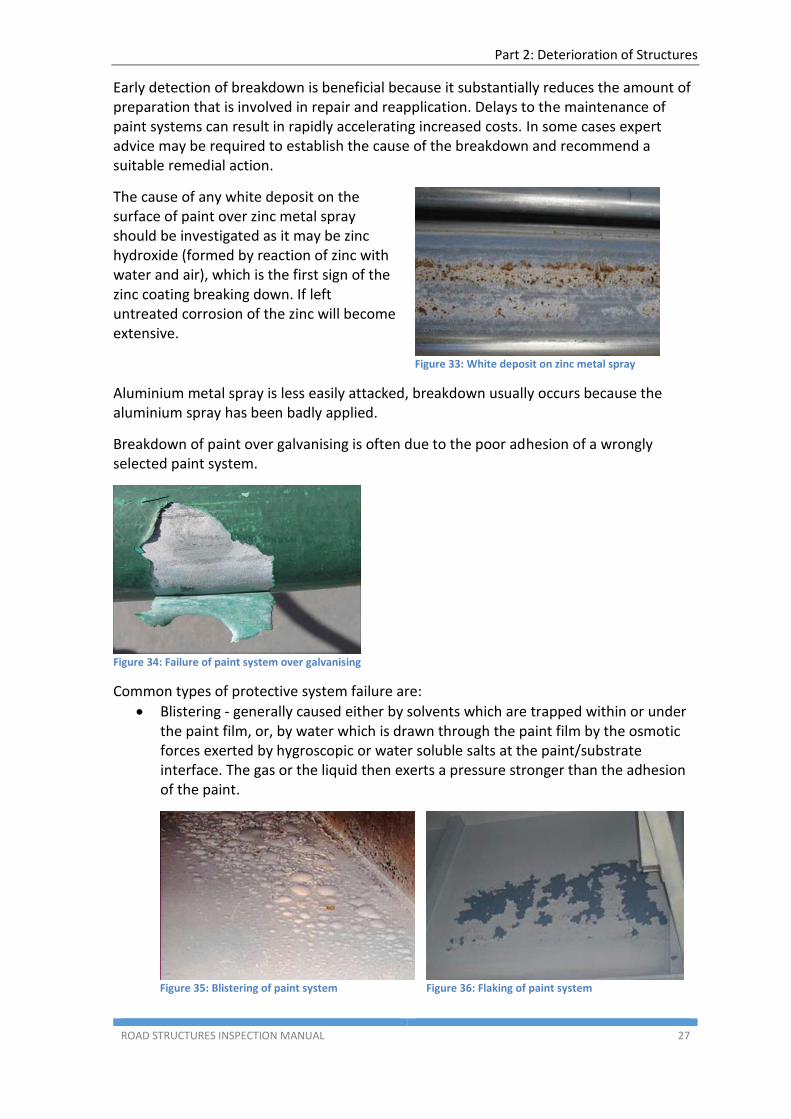
The cause of any white deposit on the surface of paint over zinc metal spray should be investigated as it may be zinc hydroxide (formed by reaction of zinc with water and air), which is the first sign of the zinc coating breaking down. If left untreated corrosion of the zinc will become extensive.
Figure 33: White deposit on zinc metal spray
Aluminium metal spray is less easily attacked, breakdown usually occurs because the aluminium spray has been badly applied.
Breakdown of paint over galvanising is often due to the poor adhesion of a wrongly selected paint system.
Figure 34: Failure of paint system over galvanising
Common types of protective system failure are:
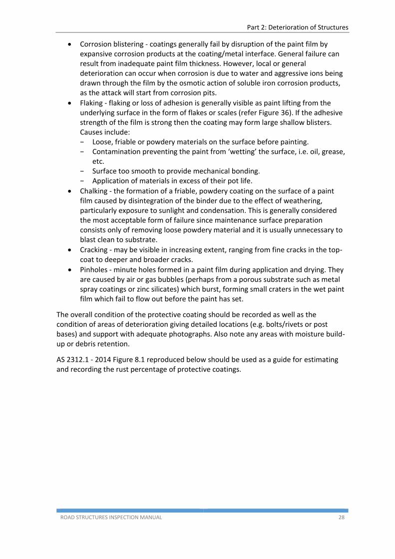
Blistering - generally caused either by solvents which are trapped within or under the paint film, or, by water which is drawn through the paint film by the osmotic forces exerted by hygroscopic or water soluble salts at the paint/substrate interface. The gas or the liquid then exerts a pressure stronger than the adhesion of the paint.
Figure 35: Blistering of paint system
Figure 36: Flaking of paint system
Part 2: Deterioration of Structures
ROAD STRUCTURES INSPECTION MANUAL 28
Corrosion blistering - coatings generally fail by disruption of the paint film by expansive corrosion products at the coating/metal interface. General failure can result from inadequate paint film thickness. However, local or general deterioration can occur when corrosion is due to water and aggressive ions being drawn through the film by the osmotic action of soluble iron corrosion products, as the attack will start from corrosion pits.
Flaking - flaking or loss of adhesion is generally visible as paint lifting from the underlying surface in the form of flakes or scales (refer Figure 36). If the adhesive strength of the film is strong then the coating may form large shallow blisters. Causes include: − Loose, friable or powdery materials on the surface before painting. − Contamination preventing the paint from ‘wetting’ the surface, i.e. oil, grease,
etc. − Surface too smooth to provide mechanical bonding. − Application of materials in excess of their pot life.
Chalking - the formation of a friable, powdery coating on the surface of a paint film caused by disintegration of the binder due to the effect of weathering, particularly exposure to sunlight and condensation. This is generally considered the most acceptable form of failure since maintenance surface preparation consists only of removing loose powdery material and it is usually unnecessary to blast clean to substrate.
Cracking - may be visible in increasing extent, ranging from fine cracks in the top-coat to deeper and broader cracks.
Pinholes - minute holes formed in a paint film during application and drying. They are caused by air or gas bubbles (perhaps from a porous substrate such as metal spray coatings or zinc silicates) which burst, forming small craters in the wet paint film which fail to flow out before the paint has set.
The overall condition of the protective coating should be recorded as well as the condition of areas of deterioration giving detailed locations (e.g. bolts/rivets or post bases) and support with adequate photographs. Also note any areas with moisture build-up or debris retention.
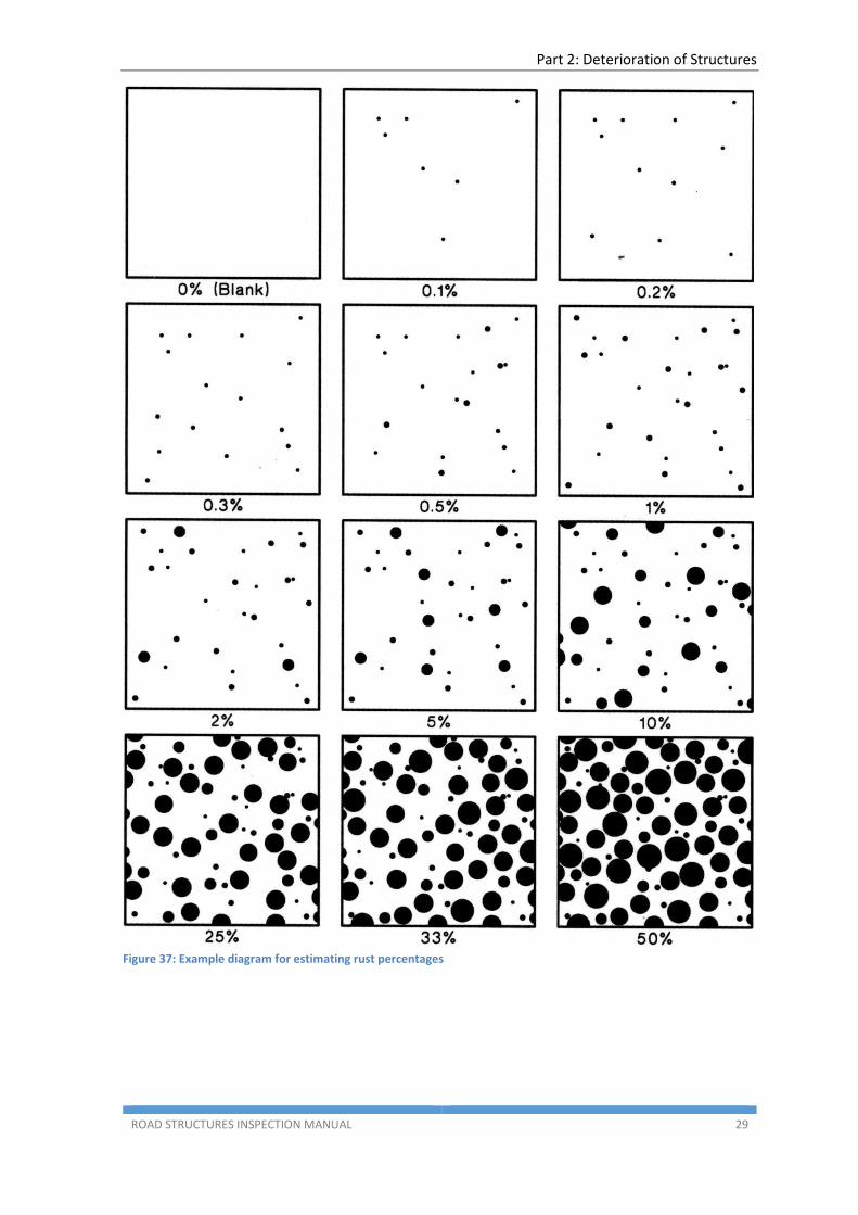
AS 2312.1 - 2014 Figure 8.1 reproduced below should be used as a guide for estimating and recording the rust percentage of protective coatings.
Part 2: Deterioration of Structures
ROAD STRUCTURES INSPECTION MANUAL 29
Figure 37: Example diagram for estimating rust percentages
Part 2: Deterioration of Structures
ROAD STRUCTURES INSPECTION MANUAL 30
1.7 Fibre Reinforced Polymers (FRP)
Fibre Reinforced Polymer (FRP) composites are used to strengthen reinforced and prestressed concrete members which are deficient in moment, shear or bursting capacity. The fibres can be Carbon, Aramid or Glass. The FRP material can be used in the form of flexible sheets to wrap around the member or in the form of plates. Plates comprise one of the three fibre types, typically in a resin or epoxy matrix. The system relies on the high tensile capacity of FRP and the bond between the FRP and the steel or concrete beam.
FRP strengthening can be detrimentally affected by overloading of the structures, extreme temperature, moisture absorption and high UV exposure. The effects are exacerbated by defects introduced in the materials during manufacture, handling and installation. The strengthening method relies entirely on the anchorage and bond of the FRP material to the base component.
The following areas should be inspected and recorded:
The ends of the strengthened area for signs of the FRP strips debonding from the epoxy resin or the resin debonding from the concrete base
The visible concrete surface at the edge of the strengthening for signs of cracking or spalling which could affect bonding between the FRP and the member
The whole of FRP surface for signs of delamination from the concrete or any irregularities in the material such as blistering or folding
Tears, cuts or crazing of the FRP material
If any area is classified as being in condition states 4 or 5, pull-off testing should be conducted in the surrounding FRP to ensure the full extent of the problem is identified. Repair should not be instigated until the whole area of the defect has been identified.
Part 2: Deterioration of Structures
ROAD STRUCTURES INSPECTION MANUAL 31
2. COMMON CAUSES OF STRUCTURE DETERIORATION
2.1 Concrete Bridges
The following section lists the various types of reinforced and prestressed concrete bridges and generally lists the main problems associated with each type.
2.1.1 Monolithic and simply-supported T-beams
Most monolithic structures are T-beam bridges with the whole structure cast insitu. Spans tend to be small but groups of as many as five continuous spans may be built this way in a bridge. This puts strains on the columns of the piers and at the abutments due to temperature movements, and it is not uncommon to see a crack and signs of movement around the beam/wall joint at the abutment. There may also be signs of tension cracking in the face of the columns of the furthest pier from the centre of the span group, due to movements and temperature. These structures are often overstressed in negative moment with cracking and staining observed at the underside of deck at the beam/deck/pier diaphragm joints.
The T-beam bridges often have insufficient shear reinforcement near the supports and diagonal shear cracking may be observed as far away as one third of the span from the support. The abutments and wings were usually cast as one and heavy cracking, spalling and movements may be observed at the wing joint especially where high abutment walls were built.
The simply-supported precast T-beam structures tended to be a later design with improved shear reinforcement of the beams and hence shear cracking is not normally seen. Some flexural cracking of the beams will normally be seen at midspan especially on structures which carry a reasonable number of heavy loads. Some beams had a locating dowel at one end of span which made that end of beam fixed with the other end free to move. The allowance for movement was often lost, with the consequence that the beam moved relative to the dowel, cracking and sometimes spalling the ends of the beams. The support directly under the beams also tended to spall due to friction, as a layer of malthoid was all that often separated the beam and substructure.
2.1.2 Precast ‘I’ beams
Precast ‘I’ beam construction began in the early 1960's, using precast high strength prestressed concrete beams with spans up to 22 metres approximately. These beams have generally performed well over the years.
The National Association of Australian State Road Authorities (NAASRA) beam sections came into use in 1970 and Type 3 and Type 4 girders have been used extensively for spans up to 25 m and 31 m respectively. Longer spans have been accomplished by casting load bearing diaphragms at the piers which encased the ends of the beams to create continuous spans. The beams were also connected on the bottom flange by heavy steel bars welded together. In recent years a ‘bulb tee’ section has been used in place of the Type 4 NAASRA beam for spans up to 36.5 metres.
Part 2: Deterioration of Structures
ROAD STRUCTURES INSPECTION MANUAL 32
The biggest problem associated with prestressed beams for large spans is the amount of hog of the beam, especially as they continue to hog further after delivery until loaded by the weight of the bridge deck. The beams can also crack towards the ends due to stressing if insufficient end steel in provided. If the beam end is cast into a diaphragm these cracks are concealed and sealed against ingress of moisture. If cracking of this nature is discovered during an inspection, it must be reported. Skewed beam ends are vulnerable to spalling damage during production at the bottom surface and at the apex of the end. The damage occurs when stress is transferred into the beams.
2.1.3 Precast prestressed inverted ‘T’ beams
These beams were used during the 1970's to produce a flat soffits to bridges crossing the highways. This was done for aesthetic reasons as the flat soffit is more appealing to the driver than the interrupted underside of an ‘I’ beam bridge. Spans ranged in the region from 10 metres to 36 metres. These beams were not an efficient section and lost favour with designers. No problems have been encountered with these types of structures to date. Top slab construction or concrete infill between beams have both been used.
2.1.4 Box girder bridges
Box girder bridges are generally cast-in-place and then post-tensioned. Some box girders have been precast in segments and post tensioned when erected in place. Problems can regularly occur during construction and at post-tensioning.
The major maintenance concern for these bridges is where grouting around the post tensioning is incomplete and does not adequately protect the steel tendons.
Serious concerns have been identified in some overseas countries where de-icing salts are used on the deck but to date no evidence of tendon corrosion has been observed in South Australian bridges.
2.1.5 Prestressed voided flat slab bridges
Cast-in-place prestressed voided flat slab bridges provide an attractive shallow depth superstructure, ideal for very wide bridges and with spans to approximately 34 metres.
Problems with flotation and distortion of the void formers have been experienced during construction, but these structures are relatively cheap, aesthetically pleasing, and have performed well up to now.
2.1.6 Reinforced concrete flat slabs
This is a type of monolithic cast-in-place multi-span bridge, typically with 5 spans which have performed very well with the slab providing considerable lateral load distribution. Structures can be continuous over a number of spans, hence there is a possibility of cracking of the columns primarily due to thermally induced movements but also if the bridge is subject to the passage of large numbers of heavy vehicles.
The deck slab in this type of bridge often has a shrinkage crack which runs almost directly down the centreline of the slab. Provided this remains dry it is of no concern.
Part 2: Deterioration of Structures
ROAD STRUCTURES INSPECTION MANUAL 33
The final span is a short cantilever from the pier sometimes with a transverse beam stiffening the end of the deck. Vertical precast concrete wall units are placed against the stiffening beam at the end of the deck to retain the approach embankment fill. Spalling can occur due to friction between the wall units caused by vertical movement of the cantilever deck. Moisture may seep through the deck/wall joint. Movement of the wingwalls can occur in bridges with high abutments due to the correspondingly high fill pressures.
2.1.7 Precast prestressed deck units
These units have only recently started to be used in South Australia, with the Park Terrace bridges over the Outer Harbor rail line.
The units are held together by transverse tensioning rods in cored holes through the beam webs.
Typically these elements are erected with a small gap between adjacent units which is subsequently filled with poured mortar. The mortar acts both as a shear key and a means of providing an even bearing surface between units for the transverse prestressing forces. The latter is applied by way of transverse stressing bars slotted through cored holes in the units. Following the application of prestress force the gaps around the bars and joints at the ends of units, at piers and abutments, are also filled with mortar.
The mortar in the joints inevitably cracks as a consequence of shrinkage and girder deflections and rotations. This permits water to penetrate from the surface to the unit soffits and substructure elements. There have been failures of the transverse stressing bars which have corroded as a consequence of this. Additionally, in regions where Alkali-Silica Reaction (ASR) is a problem that reaction is exacerbated by water leaking through the deck. The extent and severity of cracking and the production of reaction products are more pronounced in the wetter areas of the bridge. That is, adjacent to the joints between units and spans and around the kerb unit. It is imperative that deck drainage is efficient on those structures and that any cracking of the surfacing around deck joints is sealed.
The anchor plate and ends of transverse stressing bars are usually exposed. In an aggressive environment, these components may be heavily corroded. In addition, the threaded ends of the transverse stressing bars may not have sufficient length. In some instances these components are installed in the formed voids on the external concrete plank which are filled with mortar to protect them from corrosion.
Generally, the deck units alone comprise the superstructure however a reinforced concrete deck slab acting compositely with the units is often adopted in lieu of the transverse prestressing. Currently the slab is made continuous at fixed pier joints to improve ride and minimise the number of pier joints. Some cracking problems have been experienced in the deck over the piers with this type of design.
2.1.8 Precast prestressed voided ‘T’ beams
These standard beams were originally developed by VicRoads in 1986. With initial spans from 8 to 19 m, the original design has evolved to include Super-T and T-roff beams with span ranges up to 35 m and beam depths up to 1.8 m.
Part 2: Deterioration of Structures
ROAD STRUCTURES INSPECTION MANUAL 34
The potential problems identified with these beams include high neoprene bearings placed on sloping headstocks beneath the T-beams and loss of cover due to void formers floating during fabrication.
2.1.9 Decks and overlays
Reinforced concrete decks are usually cast-in-place over beams. The deck is then surfaced with either a sprayed seal or a 50 millimetre thick bituminous surfacing. Permanent or sacrificial formwork comprising thin precast concrete slabs is used to eliminate the need to remove the formwork after casting the deck particularly for bridges over highways and railway lines.
Concrete decks without surfacing were increased in depth by 12 millimetres to allow for wear by traffic. This practice was discontinued due to temperature cracking of the surface which allowed moisture to penetrate into the deck.
In order to provide composite action between beams and deck, longitudinal shear connectors (shear studs) or projecting bars are provided on the tops of beams which project into the deck. A bevelled concrete cap was cast between the deck and beams on many older bridges. Cracking of the cap can occur along the fillet line at the deck. Cracking coincident with the location of the stud or projecting bar connectors might also be visible. Unless severe, this cracking is not serious.
2.1.10 Diaphragms
At the ends of the deck a stiffening beam will be noticed joining the ends of the beams. This diaphragm (cross-girder) may be the full depth of the beams, but on some structures it will only be in the order of 200 to 250 mm in depth.
Diaphragms may also be found at midspan or at the third points to provide web stiffening against debris loads and impact forces and assist with live load distribution between beams.
On precast prestressed 'I' beam bridges continuous for live load, a wide heavily reinforced load bearing diaphragm can be found at the piers. This diaphragm is required to support the full superstructure loads and transfer that load back to a pier or to isolated columns which form the pier.
All these diaphragms should be checked for cracking and for separation from the embedded beam-ends.
2.1.11 Kerbs, footways, posts and railing
Most early concrete bridges used either narrow kerbs (sometimes tapered in cross section) or wider kerbs tapered (in plan) at the ends. These kerbs had a barrier facing which was stepped back from the kerb face. This caused a dangerous situation whereby errant vehicles could ‘take-off’ and land on top of the barrier rather than be redirected by it.
Where footways are constructed on bridges they should be inspected for pedestrian safety, i.e. ensure level of precast or cast-in-place footway slabs is good with no depressions or rises which could trip pedestrians. Moisture can penetrate footway slabs and adequate drainage of the area under the footway is required. If drainage is inadequate, dampness penetrates the deck; weed growth and efflorescence can then develop under bridge deck.
Part 2: Deterioration of Structures
ROAD STRUCTURES INSPECTION MANUAL 35
A number of different forms of posts and railings have been used on bridges ranging from guideposts, timber posts and rails, reinforced concrete posts with precast reinforced concrete rails, reinforced concrete posts with steel tube rails, steel channel posts with steel guardrails, rectangular rolled hollow steel posts and rails, and reinforced concrete New Jersey barriers and F-type barriers with steel posts with one or two steel rails on top.
Steel mesh is fixed to barriers on pedestrian bridges and should be inspected for damage and tightness of the attachment bolts.
For all bridges it is important for the steel guardrail on the approaches to attach to the bridge endposts or to continue over the bridge. This will prevent the possibility of a vehicle hitting the approach rail and being redirected directly into the endposts or striking an unprotected endpost.
2.1.12 Abutments
Abutment types vary but will generally be one of the following types:
spill through abutments using a reinforced concrete headstock supported on driven precast concrete piles or of a frame type with reinforced concrete columns supported by a footing below ground
wall type abutments either reinforced or mass concrete
wall type consisting of straight columns and a headstock with infill wall panels between the columns
masonry walls
spread footing
sill beams behind a reinforced earth wall.
Spill through abutments are possibly the most common type to be found and usually have little or no cracking of the headstock, except for shrinkage cracks. Frame type headstocks are more highly stressed and some flexural cracking may be found at midspan between the columns, or over the columns. Loss of retaining fill in front, beneath and behind the headstocks is also a common problem which requires correcting to retain the embankment fill behind the abutment.
The columns or piles are not usually a problem although cracking of the front face of piles has been noticed where the superstructure has propped the abutment against large movements of the embankment fill. This is only a problem if the cracking becomes severe. The ballast walls will often crack if beams bear hard against them or if an overhanging deck puts pressure of the top of the wall. This cracking is not considered very important provided excess moisture is not allowed through the walls.
Wall abutments are usually in good condition with differential movement between panels the only area of concern. Mass concrete walls are usually small in height and have only movement problems or in some instances scour problems of fill in front of, and beneath, the footing. Wall abutments consisting of columns with headstocks and thin infill panels can have cracking from the effects of earth pressure and shrinkage.
The side wings on the high abutment walls often move relative to the abutment walls due to earth pressure. The wings are not normally self-supporting and rely on a concrete key or
Part 2: Deterioration of Structures
ROAD STRUCTURES INSPECTION MANUAL 36
few bars of light reinforcement to hold them in place. Cracking and differential movement between the wing and the abutment wall are quite common and can be a problem if severe.
Bridges may have reinforced concrete approach slabs which rest on top of the ballast walls. These are installed to reduce live load earth pressures behind the abutments and to maintain a smooth transition onto and off the bridge for fast moving and heavy traffic thus reducing the potential for impact loads on the structure.
Stone masonry abutment walls have been constructed on older structures. Care should be taken in assessing these walls for possible signs of settlement of the blocks, settlement cracking or cracking of the wall especially under heavily loaded areas. Where loadings on the wall are at isolated points such as girders rather than a distributed load, a reinforced concrete cap may be cast on top of the wall to distribute the stress.
2.1.13 Piers
There are several types of bridge pier:
piles (pile bents) or columns supporting a crosshead (single or multiple columns)
wall piers of constant or variable thickness (some of which consist of columns with a crosshead with infill panels between the columns)
mass concrete
masonry Concrete piers can be cast in stages with horizontal construction joints between the stages. Horizontal cracking may occur around the construction joints.
All pier types may have deficiencies in reinforcement and may suffer from cracking.
With continuous superstructures and large movements occurring at the abutments, horizontal cracking of the pier wall or column face can occur as bending pressure is exerted on the wall. Bending pressure can also be put on high slender columns or piles if the bridge is on a large skew or a sharp circular curve, causing lateral cracking of the piers low down.
Long monolithic T-beam bridges often have split piers at the deck expansion joints. Cracking and spalling is a problem with these piers due to the high moments on the slender sections.
Portal frame and cantilevered headstocks have, in some instances, been found to have theoretically insufficient bending or shear capacity. This could lead to the development of structural cracking in the headstock.
Older structures may have poor quality concrete which can be eroded by the action of flowing water, sand, pebbles and grit. This can significantly reduce the amount of cover to the steel reinforcement. Shotcreting (sprayed concrete) may have been used to reinstate the concrete surface and this in itself may be eroded over time.
Part 2: Deterioration of Structures
ROAD STRUCTURES INSPECTION MANUAL 37
2.2 Steel Bridges
There are several forms of steel bridge:
Rolled Steel Joist (RSJ) and Universal Beam (UB) -pre-fabricated I-sections
plate girder (I-section welded or built-up from plate steel)
trough girder (open trough with sloping webs built-up from plate steel)
box girder (closed section possibly with two or more cells)
truss
Modern steel bridges normally comprise one of the above steel beam types with a composite reinforced concrete deck. Composite action with the deck slab significantly enhances the strength of the steel beam.
Steel beam bridges with composite reinforced concrete decks are used for longer span structures. Fabricated steel plate girders are more expensive than prestressed concrete beams and will require repainting several times during their life.
Steel superstructures may deflect substantially under load and vibrate leading to the risk of cracking of the reinforced concrete deck particularly in old structure. Moisture, corrosion and efflorescence will normally be seen at the cracks. Cyclic loading and vibration is a cause of fatigue in steel components and affects steel plates (including gusset plates in truss bridges), welds and bolts.
Steel beams may be galvanised or painted or painted over galvanising. Galvanising and painting are temporary coatings and may deteriorate or suffer from mechanical damage. All steel components must be checked for condition of the paintwork and corrosion. If no action is taken, severe corrosion may result in loss of section and perforation of plates.
Steel beam bridges have steel bracing frames at the supports and at intervals throughout the length of the bridge to provide stability in the temporary state and to prevent lateral buckling in permanent conditions. These components and their connections must be inspected in the same way as the main members.
Splice plates are used to connect beam webs and flanges. These may be riveted, bolted or welded. All welded connections, splices and stiffeners should be closely inspected for any signs of cracking of the weld or metal immediately adjacent to it. Progressive increase in crack length and width is a symptom of fatigue and is caused by cyclic loading. Position and size of cracks must be accurately recorded and reported.
Bolted and riveted connections require inspection to check whether all connections are intact and tight. Missing bolts and nuts may arise as a result of fatigue failure of the bolt shank. Loose bolts can be detected by cracks in the coating system, by permanent displacement or by relative movement of the connected components as vehicles cross the deck.
Signs of excessive wear at pinned joints in trusses or other movement joints should be recorded.
Surfaces at member connections should be clean and free from debris, dirt and moisture as these are cause for corrosion of connections and connecting members. Uncontrolled
Part 2: Deterioration of Structures
ROAD STRUCTURES INSPECTION MANUAL 38
drainage through leaking deck joints will discharge onto the ends of beams, cross bracing and bearings leading to corrosion. Signs of this should be recorded and rectified. Similarly, accumulation of water within closed units (e.g. box girders), such as leakage or condensation will lead to deterioration of the protective coating and eventually corrosion.
Longitudinal girders and truss members should be inspected for signs of deformation. This may be evidence of buckling of the member caused by overloading or sign of inadequate bracing and must be reported.
The thin steel sections are also susceptible to permanent deformation caused by vehicle impact and if severe can significantly reduce the load carrying capacity of the structure. This can be caused by impact from a high vehicle travelling under bridge damaging the bottom flange or chord member, or by vehicles at deck level causing damage to through girders and trusses.
2.3 Timber Bridges
Timber bridges are not common in South Australia. There are currently only a small number of bridges in the State Road Network that comprise timber components:
footbridges with timber decks
Birkenhead Bridge bascule spans have timber decking
disused (bypassed) heritage or historic timber bridge
2.3.1 Decking
Timber decking generally comprises three types:
cross-beams with longitudinal decking
cross-decking with thin longitudinal running planks
plywood decking
The cross beams are generally used on more heavily trafficked roads and the planks are usually used on minor roads. Plywood decking has been used on the Birkenhead Bridge bascule spans as a lightweight alternative to steel or concrete.
2.3.1.1 Cross Beams with Longitudinal Decking
Timber cross-beams should be inspected for end rot, top rot, bulging at the top due to ingress of moisture, sagging at mid-span due to excessive span length, fracture and severe splitting. Severe splitting and top rot can often be caused by spiking of the decking. They should be firmly bolted to the beams and all bolts should be regularly checked to ensure tightness. The effect of termite damage on small sections can be severe. Careful inspection is required to identify if there is evidence of termite.
Long-decking should be laid in long continuous lengths and span at least three cross-beams unless designed specifically for simple spans. It should be securely bolted to the cross-beams at each end and at alternate intermediate cross-beams. This is done to stop flexing of the long-decking under load and to reduce the risk that the bolts will pull through the ends of the long-decking planks. Mild steel angle cleats are commonly used to bolt the long-decking to the cross-beams. These offer a rigid point against which the bolts can be tightened. Mild steel plates can bend on tightening and the bolts can work loose.
Part 2: Deterioration of Structures
ROAD STRUCTURES INSPECTION MANUAL 39
Long-decking should be laid with the heartwood down to prevent it rotting and splitting at the centre or curling up at the edges.
As the timber shrinks and dries, gaps will form between the planks and action may be required to close up the gaps by inserting additional thin sections of plank. This is especially important on bridges used by cyclists.
2.3.1.2 Cross Decking (Transverse Planks)
Timber cross-decking is not as rigid as the long decking described above. In many cases the cross-decking is only spiked to the spiking plank or timber stringer below. This type of decking generally becomes loose and requires continual tightening of bolts if they are used. Longer spikes are often used but this only compounds the splitting and spike rot. Timber running planks are usually supplied with cross-decked bridges. These planks aid load distribution to the cross-decking. The running planks are usually of a thin section being only 40mm to 50mm thick. They are usually only spiked and easily become loose. These planks tend to split easily requiring constant replacement and also form a moisture trap which hastens rot of the cross-decking below. Some bridges have fill or asphalt over the cross-decking , although it does offer improved load distribution, this is not generally successful as the surface becomes uneven and cracked due to cross-decking movement. Surfacing also tends to trap a reservoir of moisture which accelerates timber rot.
Transverse deck planks should also be inspected for end and top rot (particularly in the kerb region) bulging on top due to ingress of water, sagging at midspan due to excessive span length, fracture and severe splitting. Severe splitting and top rot can often be caused by spiking of decking and the practice should be discouraged except at the outer edge connection. The inspector must always be alert for signs of termite damage as the consequence on these small sections can be severe.
2.3.1.3 Plywood Decking
Plywood decking has been used on the Birkenhead Bridge bascule spans as a lightweight alternative to steel or concrete.
Differential movement of plywood sheets under traffic loads and inadequate sealing of joints can cause damage to the roadway surface. The exposed outer ends of the plywood sheets should be examined for evidence of delamination.
Defects experienced on the Birkenhead Bridge plywood decking include the following:
Deterioration of deck traffic surface exposing timber elements and bolts
Failed deck traffic surface allowing water leaks through the timber decking
Timber decking rotting
Plywood sheets deflecting due to loose cleats
Loose or missing anchor bolts
Other common defects of plywood decking and the root causes include the following:
Loss of cross sectional area in the bottom layer of due to abrasion between the girder and plywood panel.
Abrasion between sheet joints caused by material from the deteriorated deck wearing surface working their way between the sheets.
Part 2: Deterioration of Structures
ROAD STRUCTURES INSPECTION MANUAL 40
Deck wearing surface had been lost over significant areas resulting in the top scarf jointed layer being worn away due to traffic abrasion in places.
Deck bolt washers are less than the specified size causing localised crushing of wood fibre around the bolts. This has contributed to loose panels which are able to ‘grind’ and flog on the girders.
Broken pieces of deck wearing surface work their way down between the sheets contributing to the grinding action of plywood sheets on the girder seating.
Plywood panels are loose, evidenced by the pronounced transverse cracking in the deck wearing surface over every panel joint and by the total loss of the bottom outer layer of the plywood - girder interface.
2.4 Deck Joints
Purpose of deck joints is to seal the gap between the end of a bridge deck and the fender wall against the ingress of water and debris. Joints are designed to accommodate thermal and rotational movements in the bridge deck, normally by the use of a flexible seal in the gap. A number of different types of expansion joint have been used in the past.
Early bridges featured short spans and simple supports for which the required movement capacity of the joint was small. Materials with a small movement capacity such as cork, bituminous impregnated fibreboard, butyl impregnated polyurethane foam, styrene and foam strips were used. Asphalt, rubberised bitumen or polyurethane was often poured on top of the joint to seal it from moisture penetration. Many of these joints failed due to the joint material debonding or being inelastic. Sealant placed too high in the joint gap tended to crack and was lost.
As spans increased, so did the width of expansion joint, and compression seals were required to cater for the movements expected. Neoprene tube was the earliest recorded type of seal but proved to be inelastic and often fell through the joint leaving it completely open. Compression seals were then developed. These can be placed between concrete surfaces, steel angles, steel plates and proprietary 'concrete' headers/nosings. Compression seals may debond and gradually move upwards to the top of the joint where traffic damages the seal or, in some cases, completely removes it. Steel angles are susceptible to impact loading from wheels, especially if dry packed mortar has been used beneath the angle. The mortar breaks up and the ensuing loss of support breaks the anchor bars holding the angle into the deck. The angles can then vibrate and move under load which cracks the bitumen at the edge of the angle.
A further type of expansion joint comprises a cellular neoprene seal attached to aluminium strips which in turn are bolted to the deck and abutment. These strips or rails may lift and break if the holding-down bolts are not properly secured into the underlying concrete. Holding-down bolts in cored holes are more vulnerable than bolts cast into the concrete although the latter type is at-risk if the concrete around the cast-in anchorage is not compacted correctly or if the holding-down bolts are not tensioned correctly. The seal and aluminium strips/rails may then be damaged possibly leading to a hazard for vehicles.
Steel finger plates and steel sliding plate joints have been used on larger span bridges. These joints may not incorporate a seal to prevent moisture penetration. Sliding plate joints can also vibrate loose causing a danger to traffic. These joint types were superseded by
Part 2: Deterioration of Structures
ROAD STRUCTURES INSPECTION MANUAL 41
heavy duty rubber joints of the Transflex type comprising steel plates in an elastomeric plank. Debonding of the metal and rubber sections can occur in this type of joint and must be reported. Reinforced concrete nosings were used to support the joints but these can crack and fragment under repeated impact loads.
Asphaltic plug joints are used on bridge decks with small movements and sufficient asphalt cover. This joint consists of a 50mm thick (minimum) hot mix of selected aggregate and an elastomer modified bitumen binder and has the appearance of a strip (approximately 500mm wide) of dark asphalt. Defects may include fretting and loss of asphalt and movement of the steel cover plate (situated at the bottom of the joint under the asphaltic plug) where this has been used.
Cold-poured sealant joints are used mainly as replacement joints for bridges with a small range of movement. There have been examples of the use of this type of joint in new bridges in Victoria. This class of joint comprises a cold-poured sealant over a circular backing strip between proprietary concrete nosings/headers. The thickness of sealant is generally half the installation width of the joint. Joints of this type may fail by tearing or by debonding from the nosing leading to loss of the seal. Defects of this nature must be reported.
2.4.1 Joint Defects
Most joint defects occur because installation has not been carried out in accordance with the manufacturers or Code requirements. For example, anchor bolts become loose because they were not installed and tightened correctly, or joints leak because the treatment at kerbs, medians or parapets is not in accordance with the design details.
Some common service faults are listed below:
Loose or missing anchor bolts
This is the most common service fault, and is generally due to inadequate initial load in the bolt. Re-tightening of all bolts after a period of service is recommended. However, loose or missing bolts may be due to failure of the bolt or ferrule.
Use of unsuitable anchor bolts
All anchor bolts should be hexagon headed – use of socket head bolts such as “Unbrako’ is unsuitable because of the difficulties of re-tightening and replacement.
Excessive water leakage
It is likely that there will be some water leakage through most deck joints. It is important that leakage is minimised because it results in staining of the substructure, and deterioration of steelwork and concrete. All deck joints should be inspected from below the joint to assess the extent of leakage, and if possible to locate the cause of seal failure.
Loose, damaged or missing seals
Deck joint seals may be damaged or worn by vehicles or sharp objects such as stones, or may be poorly installed or of unsuitable material. Inspection should include examination along the seal in order to detect defects including loss of bond between lengths of seal.
Part 2: Deterioration of Structures
ROAD STRUCTURES INSPECTION MANUAL 42
Excessive debris in joint
Joints such as strip seal type should be designed to expel debris by the passage of vehicle tyres.
Joints having a deep recess such as strip seals with excessive ‘drape’ may be filled with debris especially adjacent to kerbs. Regular routine maintenance may consist of cleaning with compressed air or water, but the seals may need to be replaced to provide a long term solution.
Joint width outside design movement range
For good vehicle riding characteristics, the maximum width of expansion joint gap should be 70mm (measured square to the joint).
Variation in joint width
Deck joints should have uniform gap width, and variation in width along the joint may be due to poor initial installation, loose fittings or plan rotation of the bridge.
Excessive noise
Most deck joints cause some tyre noise, but loose components of joints such as sliding plate type can cause excessive noise. For this reason sliding plate joints are not recommended by the current Australian Bridge Design Code for vehicular traffic, but are used on footways to provide a smooth surface.
Damage of joint nosing
Where a concrete strip or ‘nosing’ is used adjacent to deck joints, inadequate reinforcement or compaction of the concrete may cause cracking or spalling of the nosing. These faults can result in unsafe driving conditions and should be repaired as soon as possible.
2.5 Step (Half) Joints
Step joint or half joint is a type of articulation in which a suspended beam or deck slab (the drop-in span) is supported on a short cantilever or corbel as shown in Figure 38. Step joints can be found on both concrete and steel structures on existing structures.
Step joints are normally positioned several metres away from the pier or abutment and often over live traffic or wide waterways. Traffic management, extensive scaffolding, machinery or custom designed suspended platforms are required to provide a safe access for personnel to inspect and maintain the joints.
This type of construction detail inherently leads to leakage through the joint. This causes debris and moisture to accumulate at the beam seats and eventual deterioration of the concrete and steel surfaces. Due to the difficulty in inspection and maintenance of step joints, VicRoads no longer permits the use of this type of construction detail.
Level 2 inspections shall identify the presence of step joints on the comments sheet. The inspector shall inspect step joints using binoculars unless the step joint is readily accessible. The inspection shall make comment and take photos on any staining, buildup of debris, or
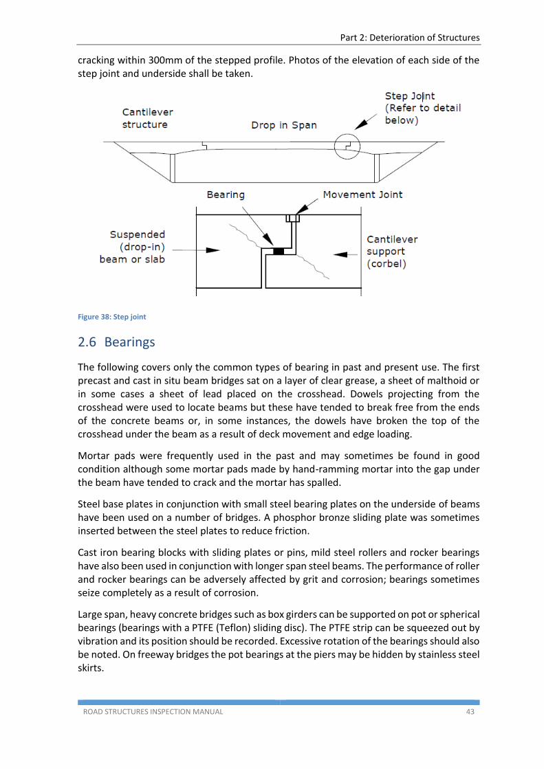
Part 2: Deterioration of Structures
ROAD STRUCTURES INSPECTION MANUAL 43
cracking within 300mm of the stepped profile. Photos of the elevation of each side of the step joint and underside shall be taken.
Figure 38: Step joint
2.6 Bearings
The following covers only the common types of bearing in past and present use. The first precast and cast in situ beam bridges sat on a layer of clear grease, a sheet of malthoid or in some cases a sheet of lead placed on the crosshead. Dowels projecting from the crosshead were used to locate beams but these have tended to break free from the ends of the concrete beams or, in some instances, the dowels have broken the top of the crosshead under the beam as a result of deck movement and edge loading.
Mortar pads were frequently used in the past and may sometimes be found in good condition although some mortar pads made by hand-ramming mortar into the gap under the beam have tended to crack and the mortar has spalled.
Steel base plates in conjunction with small steel bearing plates on the underside of beams have been used on a number of bridges. A phosphor bronze sliding plate was sometimes inserted between the steel plates to reduce friction.
Cast iron bearing blocks with sliding plates or pins, mild steel rollers and rocker bearings have also been used in conjunction with longer span steel beams. The performance of roller and rocker bearings can be adversely affected by grit and corrosion; bearings sometimes seize completely as a result of corrosion.
Large span, heavy concrete bridges such as box girders can be supported on pot or spherical bearings (bearings with a PTFE (Teflon) sliding disc). The PTFE strip can be squeezed out by vibration and its position should be recorded. Excessive rotation of the bearings should also be noted. On freeway bridges the pot bearings at the piers may be hidden by stainless steel skirts.
Part 2: Deterioration of Structures
ROAD STRUCTURES INSPECTION MANUAL 44
Elastomeric bearing are now in common use; either as a thin strip or pad usually 20mm thick, or in a rectangular form incorporating metal plates between the layers of elastomer. The thinner bearing strips/pads are normally used to support small span beams. However, if the bearing pedestals are poorly constructed then some parts of a pad may not carry load.
If poorly designed or manufactured, elastomeric bearings with steel plates can suffer from irregular bulging and shearing at the elastomer/metal plate interfaces. Elastomeric bearings rotate and deform in shear as the bridge moves and, in extreme cases, this can cause lift-off of the bearings at the edge, leading to over-stress of the opposite edge of the bearing. Irregular and uneven pedestal construction is a common problem associated with large bearings and can also lead to uneven development of stress in the bearings -overstress in some locations and little or no stress in others.
Creep, shrinkage and elastic shortening due to post-tensioning can cause excessive shear stress on the bearings in box-girder bridges. Bearings may require resetting in this circumstance. This will require the beam to be jacked-up -rarely done unless deformation is excessive. Actual deformation should be measured and reported if it is thought to be excessive.
Slippage (walking) of elastomeric bearings can occur, particularly in older structures where bearings retainers were not used. More recent designs (since the 1980s) incorporate bearing retainers that prevent slippage.
2.7 Culverts
2.7.1 Concrete Box Culverts
Early box-culverts were cast-in-place and many of these early examples suffer from corrosion of reinforcement, cracking and spalling due to lack of concrete cover, porous concrete and/or ingress of moisture. Once corrosion, cracking and spalling has commenced, progressive deterioration generally ensues.
Small precast inverted U culverts with precast concrete lids may exhibit significant cracking and spalling due to inadequate cover to reinforcement.
Larger precast concrete crown units have also been extensively used. Link slabs have been used between units in multi cell culverts to reduce construction costs and time. The link slabs take the place of the intermediate row of precast crown units by spanning across the gap between alternate rows of crown units. The link slabs may be either precast in a casting yard, or cast on top of the culvert base slab and then lifted into position. No service problems have been noted with these slabs at present.
Box culverts are more susceptible to concrete problems under the edge of the seal if the shoulders are unsealed.
2.7.2 Concrete Pipe Culverts
Large pipe culverts have been used for many years. The pipes are susceptible to many defects that may arise from inadequacies in manufacture, handling, stacking, transportation and installation
Part 2: Deterioration of Structures
ROAD STRUCTURES INSPECTION MANUAL 45
Large pipes may have a lifting hole. It is important that the hole be accurately positioned at the pipe obvert as elliptical reinforcement is used.
Pipe culverts should be inspected for the presence of cracks, spalls, line and level and stability of headwalls and wing walls.
2.7.3 Masonry Arch Culverts
Refer to Section 1.4 Masonry.
2.7.4 Corrugated Metal Structures - Pipes and Arch Culverts
Large buried corrugated steel pipe and arch culverts have been used in South Australia for many years. A very limited number of corrugated aluminium culverts have also been used. Buried corrugated metal culvert structures are recognised worldwide as a high risk structure, comprising a thin wall section of steel or aluminium that is prone to corrode longitudinally at the top of the wetted area or in the invert.
Unequal lateral soil pressure applied during construction, long term settlement or scour may lead to permanent deformations and instability of corrugated metal structures. These issues may also develop as a result of lack of thickness specified in the design process, loose, corroded or missing bolts, corrosion and loss of section of metal plates.
Significant deformations are potentially a high risk to the structural integrity and those who inspect and maintain them. Inspectors should not enter a corrugated metal pipe that has significant corrosion or deformation. Reference should be made to the Principal Engineer Bridge Assets as a Level 3 investigation should be initiated as a matter of urgency.
Corrosion of steel culvert panels commences when the galvanised or other protective coating is damaged by impact or by abrasion resulting from the action of soil-particles in the flowing water or if the coating is lost through the normal sacrificial process. Contact with aggressive water or soils (natural ground or in the backfill) or other materials such as cattle droppings may also contribute to corrosion.
It may only be possible to assess the loss of metal in the water-side (open side) surface of the structure walls around the invert and within the splash-zone above water-level. There may be significant loss of metal thickness to the buried (soil-side) faces of the structure and, unless the metal becomes visibly perforated or so thin that it can be pierced with a hand pick or chisel point, it will not be possible to fully assess the degree of corrosion on the soil-side. If a detailed assessment of soil-side corrosion is required, this can be achieved by cutting samples from the wall-panels or by excavation to expose the structures. The extent and method of cutting or excavation must be agreed with the Principal Engineer Bridge Assets in order to prevent the risk of de-stabilising the structure. It may also be possible to use non-destructive methods of testing such as ultra-sound to measure the thickness of the metal.
Part 2: Deterioration of Structures
ROAD STRUCTURES INSPECTION MANUAL 46
Issues that may require action to enable detailed inspection:
the invert of the structure may be obscured by debris and or submerged below water-level
if the structure is being used as a cattle underpass, the invert may be obscured by gravel and cattle-droppings
if the structure is being used as a pedestrian underpass, the invert may be paved.
Features of a potentially unstable structure:
the walls may be deformed
the soffit may be propped
the invert may be severely corroded and there may be significant loss of metal
the backfill may be eroded or softened.
2.8 Major Sign / Gantry Structures
Large cantilever signs, butterfly signs and sign gantries are increasingly prevalent on the network and constitute major structures in their own right.
Sign and signal gantries either span or cantilever over part of the carriageway.
The consequences of any failure or partial failure of one of these structures has the potential to cause significant disruption to the network and potential loss of life.
High wind forces on signs and other attachments will produce large twisting forces on supports, connections, columns and base connections. Furthermore they are also susceptible to wind induced vibrations with associated potential fatigue related defects (particularly in hold-down bolts and welded connections) which could lead to collapse of the structure onto trafficked lanes.
Key areas for inspection include:
missing, loose or damaged nuts/bolts
cracked welds
butt welds at structural connections
corrosion
splits or ruptures in columns and stiffeners
impact damage
tilting columns
crushed/missing mortar beneath base plates
exposed levelling nuts beneath base plate (levelling nuts should not be engaged in carrying load after mortar has been placed)
base plates or other steelwork which has been incorrectly (i.e. not in accordance with the drawings) encased in grout or concrete (any affected components will need to be exposed to determine the extent of any corrosion)
cracking/spalling of concrete around base plates.
Nuts on hold-down bolts should have been checked at installation for tension and marked. The inspector should check the marks and note if there has been any movement or loosening of the nuts.
Part 2: Deterioration of Structures
ROAD STRUCTURES INSPECTION MANUAL 47
2.9 Retaining Walls
Defects/deterioration associated with the various wall types can be attributed to the construction material(s) or stability of the retained (or founding) material.
Material related defects will typically be as described in Section 1. Any connections/fixings utilised in the wall construction type must also be considered, with particular attention paid to tightness, corrosion and missing or incorrectly installed fixings. Embedded materials not accessible for inspection (e.g. soil nails, anchors, etc.) may require specialist inspection to evaluate condition unless consideration was given at time of design/construction (e.g. inclusion of additional ‘sacrificial’ nails able to be removed for inspection or installation of load cells to monitor tension in embedded components).
Indicators of potential issues with stability of retained or founding material can include:
cracking/slumping of carriageway or shoulder parallel to the retained face may indicate settlement, outward movement or loss of retained material
change in alignment of the top face of the retaining wall or guardrail/barrier
change in angle of the retaining wall indicating rotation of wall
erosion or removal of material to front face of the retaining wall
blocked/inadequate drainage (weep) holes to relieve pore pressure behind walls.
In addition to the above, the impact of any proposed change in land use adjacent to a retaining structure (e.g. widening or realignment of carriageway (even temporarily to facilitate maintenance) must be carefully considered as the effects may not have been considered at the design stage.
2.10 Noise and Visual Screen Walls
Noise attenuation and visual screen walls are normally located along major roads where there are residential or light commercial developments at the right of way boundary. They are commonly made from a range of materials including timber (plywood), concrete, steel, aluminium, acrylic and polycarbonate materials.
Some noise attenuation walls have built-in lighting powered by solar panels. These are subject to electrical problems and to vandalism.
Visual screen walls are similar to noise attenuation walls but are normally used to shield unattractive commercial or industrial development along important roads or shared use pedestrians routes.
Noise attenuation and visual screen walls must be inspected in order to prevent collapse onto trafficked carriageways or pedestrian ways.
Problems can occur due to:
Rot and termites in timber particularly at or just below ground level
Corrosion in steel and cracked welds
Reinforcement corrosion
Cracking and spalling concrete
Collapse of panels due to failure of fixings including self-tapping screws
Part 2: Deterioration of Structures
ROAD STRUCTURES INSPECTION MANUAL 48
Cracking of concrete and plastic panels
Graffiti
The inspector should also observe and record problems associated with ground movement that may cause columns to move and allow panels to fall out. The footings should be inspected for cracking or spalling around the cast-in-situ or bolted connections.
2.11 Ferry Ramps
Ferry ramps are concrete structures therefore concrete related defects should be anticipated. These are described in Section 1.2.
Defects specifically expected to occur are:
Settlement of slabs
Concrete cracking and spalling
Abrasion of the concrete slab by the ferry run-on ramps
Joint deterioration
Corrosion of deadman structural steelwork attachments
Scour of soil surface of unfaced shoulders
Excessive vegetation growth on unfaced shoulders
2.12 Busway
Deterioration of the busway tracks is associated with the concrete construction material along with the stability of the concrete pylons.
Concrete material defects are described in Section 1.2. In addition, debris buildup can be an issue.
Vegetation overgrowth and graffiti are managed via routine road maintenance.
2.13 Cattle Grids
Problems with cattle grids can occur due to:
Concrete cracking and spalling
Settlement and cracking at abutments
Pavement cracking
Corrosion on beams and baffle plates
Excessive buildup of gravel and debris under the grid
Grid misalignment
2.14 Tunnels
The Heysen Tunnels are closed each three months to allow for major maintenance procedures. Structural inspections of the Heysen Tunnels should be scheduled to coincide with these programmed tunnel closures.
Part 2: Deterioration of Structures
ROAD STRUCTURES INSPECTION MANUAL 49
Tunnel inspections are devoted to assessing the condition of the structural elements of the tunnel, specifically the concrete portals, tunnel lining and fixtures, and the jet fan mountings.
Problems encountered include:
Concrete spalling
Efflorescence
Shrinkage cracks in wall lining
Water leakage
Damaged wall panels
Loose and/or missing bolts for attachments
2.15 Causes of Deterioration not related to Construction Materials
The following items (which are not caused by defective materials) must be inspected and maintained in order to avoid structural deterioration:
2.15.1 Damage due to Accidents
The most common components affected by vehicular impact are barriers, kerbs, footpath slabs and end posts which can be severely abraded, spalled or damaged. Damage is usually self-evident.
Other areas that can be affected are columns, outer beams or soffits of overpass structures. Steel beams are particularly susceptible to damage from over-height vehicles which can cause severe deformations to the bottom flange or web of the member.
Bridges over navigable waterways may also have damage to pier columns and pile caps due to impact of vessels. The damage may be sufficient to cause major structural damage or movement of the column requiring an assessment of the structural adequacy of the bridge, or cause abrasion and spalling of concrete which can result in eventual corrosion of reinforcement.
2.15.2 Drainage
Inadequate or impaired drainage may affect a bridge in several ways:
flooding of the bridge deck which may create a serious traffic hazard
water flowing over concrete, steel surfaces or bearings may result in corrosion or impaired performance of bearings
build-up of debris retains moisture and promotes corrosion
uncontrolled discharge from the deck can cause erosion of approaches, batters and possibly undermine foundations
leakage from the bridge deck through joints and cracks can cause unsightly staining of beams, piers and abutments
Inadequate road-surface drainage from the bridge approaches can also cause erosion, piping and washout or scour of the approach embankment and batter slopes, particularly in areas where flows are concentrated at the ends of bridges, near the end post and at ends
Part 2: Deterioration of Structures
ROAD STRUCTURES INSPECTION MANUAL 50
of kerbs or service ducts. These areas should be inspected particularly after heavy rain or flooding.
2.15.3 Debris
Buildup of debris on the upstream side and on the deck of a bridge can cause the following adverse effects:
very high imposed loads on the bridge possibly exceeding the design load
impact loads particularly on slender piles leading to breakage of pile bents and/or total loss of piles
blockage (partial or total) of the waterway which can cause flooding upstream, exacerbate problems of scour, undermine foundations and in extreme cases result in diversion of the watercourse
Buildup of debris is dependent on upstream catchment conditions/use and its impact is usually most severe in bridges with small openings or low freeboard.
Additionally, the build-up of debris below a structure may become a fire hazard, increasing the risk of fire damage to piles and headstocks.
2.15.4 Vegetation
Uncontrolled and excessive growth of vegetation beneath, adjacent to or on a structure can have both positive and negative consequences. In the case of bridges and culverts, the presence of vegetation is typically negative as it can result in:
fire hazard
blockage of waterway
retention of moisture around key components (bearings, girders, headstocks, etc.)
build-up of leaf litter across decks will block scuppers and promote decay
root ingress and growth can displace and damage components
limited access to and poor visibility of structure components
limited sight distances across structures
overhanging limbs pose a hazard to road users.
For retaining structures, the presence of vegetation on the up and down slope will typically contribute to slope stability as well as improving resistance to erosion however large trees can become unstable and cause substantial damage if they fail. Vegetation growth on retaining structures limits access and visibility of components and, as for bridges and culverts, root ingress and growth can displace/damage components.
2.15.5 Waterway Scour
Scour in watercourses and drainage paths has the potential to cause significant damage to the environment and engineering infrastructure.
Scour is the erosive action of flowing water, resulting in the removal, and subsequent deposition, of material from the bed and banks of streams and from around the piers and abutments of bridges.
Part 2: Deterioration of Structures
ROAD STRUCTURES INSPECTION MANUAL 51
Scour can result in a general lowering (degradation) or raising (aggradation) of the river bed, lateral erosion of river banks or the development of localised scour holes around piers/piles and abutments.
It is a requirement of Level 2 inspections to capture the waterway profile for bridges and culverts crossing waterways. This allows for the monitoring of general waterway behaviour over time.
Indications of recent ‘fresh’ scour activity include:
loss of vegetation/exposed roots on waterway bank
exposed piles
undermining/voiding to toe of bank or provided batter protection
evidence of batter protection settlement such as cracking in rigid protection or slumping in flexible/semi-rigid protection
loss of abutment batter protection
undermining/voiding beneath abutment/piers
accumulation of loose sediment adjacent river banks around piers (the latter may be indicative of localised scour holes being backfilled with loose material as water levels recede)
Degradation and localised scour can result in progressive settlement or movement of abutments, piers, culverts and any other structure in or adjacent to the waterway which, if not rectified can lead to total failure of the structure.
2.15.6 Movement of the Structure
Settlement and horizontal displacement of piers and abutments can be caused by:
Scour
Land slips around or under the bridge
Earth pressure resulting from long-term settlement or movement of the embankment fill and underlying ground
Collisions with vehicles and vessels
Locking of bearings or expansion joints
Visual indicators of settlement and horizontal displacement:
Closure or excessive opening of expansion joints
Contact between the superstructure and abutment fender wall with associated cracking and spalling
Steps in horizontal and vertical alignment of the road surface and bridge barriers, particularly at movement joints
Cracking of abutments and columns or piers
Cracking or excessive settlement of the approach embankments and in beaching or heave at the embankment toe
Scour causing undermining of the foundations
Out of verticality of adjacent roadside columns, poles and fences etc.
Observations of these indicators are an important aid in determining whether movement is continuing, seasonal or has ceased. Movements of this nature can continue over a long
Part 2: Deterioration of Structures
ROAD STRUCTURES INSPECTION MANUAL 52
period of time and the ability to make comparisons with past inspections is useful in understanding the cause(s) of the movement and the appropriate response.
2.15.7 Condition of Approaches
The purpose of the approach embankment is to provide a stable transition between the bridge and adjacent pavement. Often it is also required to provide horizontal, and sometimes vertical support for the abutment foundation.
The most common defect of approach embankments is usually excessive settlement adjacent to the bridge abutment which causes unsatisfactory riding quality and possible damage to deck and expansion joints.
This can be caused by poorly compacted embankment, and or continuing settlement of the underlying ground. Instability of ground and embankment can also be observed in its early stages by excessive settlement or movement of the embankment.
It should be noted that while the subsidence behind bridge abutments is often attributed to settlement of embankment fill the defect may often be caused by other factors including:
settlement or rotation of walls which allows loss of embankment material generally as a result of leaching of fines
settlement of infill panels or backing slabs, which generally occurs as a result of softening of moisture susceptible founding material or following scouring of the footing
erosion, piping, washout and scour of the embankment, particularly after heavy rain or flooding, or due to inadequate or blocked drainage.
Part 2: Deterioration of Structures
ROAD STRUCTURES INSPECTION MANUAL 53
(This page has been left blank intentionally)