Embed Size (px)
Citation preview
Reference numberISO/TR 14121-2:2007(E)
© ISO 2007
TECHNICAL REPORT
ISO/TR14121-2
First edition2007-12-15
Safety of machinery — Risk assessment — Part 2: Practical guidance and examples of methods
Sécurité des machines — Appréciation du risque —
Partie 2: Lignes directrices pratiques et exemples de méthodes
Licensed to RISK ENGINEERING GCCH/CHRISTINE BLACHISO Store order #:868106/Downloaded:2007-12-05Single user licence only, copying and networking prohibited

ISO/TR 14121-2:2007(E)
PDF disclaimer This PDF file may contain embedded typefaces. In accordance with Adobe's licensing policy, this file may be printed or viewed but shall not be edited unless the typefaces which are embedded are licensed to and installed on the computer performing the editing. In downloading this file, parties accept therein the responsibility of not infringing Adobe's licensing policy. The ISO Central Secretariat accepts no liability in this area.
Adobe is a trademark of Adobe Systems Incorporated.
Details of the software products used to create this PDF file can be found in the General Info relative to the file; the PDF-creation parameters were optimized for printing. Every care has been taken to ensure that the file is suitable for use by ISO member bodies. In the unlikely event that a problem relating to it is found, please inform the Central Secretariat at the address given below.
COPYRIGHT PROTECTED DOCUMENT © ISO 2007 All rights reserved. Unless otherwise specified, no part of this publication may be reproduced or utilized in any form or by any means, electronic or mechanical, including photocopying and microfilm, without permission in writing from either ISO at the address below or ISO's member body in the country of the requester.
ISO copyright office Case postale 56 • CH-1211 Geneva 20 Tel. + 41 22 749 01 11 Fax + 41 22 749 09 47 E-mail [email protected] Web www.iso.org
Published in Switzerland
ii © ISO 2007 – All rights reserved
Licensed to RISK ENGINEERING GCCH/CHRISTINE BLACHISO Store order #:868106/Downloaded:2007-12-05Single user licence only, copying and networking prohibited

ISO/TR 14121-2:2007(E)
© ISO 2007 – All rights reserved iii
Contents Page
Foreword............................................................................................................................................................ iv Introduction ........................................................................................................................................................ v 1 Scope ..................................................................................................................................................... 1 2 Normative references ........................................................................................................................... 1 3 Terms and definitions........................................................................................................................... 1 4 Preparation for risk assessment ......................................................................................................... 1 4.1 General................................................................................................................................................... 1 4.2 Using the team approach for risk assessment.................................................................................. 2 5 Risk assessment process.................................................................................................................... 3 5.1 General................................................................................................................................................... 3 5.2 Determination of the limits of the machinery .................................................................................... 3 5.3 Hazard identification............................................................................................................................. 4 5.4 Risk estimation ..................................................................................................................................... 6 5.5 Risk evaluation.................................................................................................................................... 10 6 Risk reduction ..................................................................................................................................... 11 6.1 General................................................................................................................................................. 11 6.2 Elimination of hazards by design...................................................................................................... 12 6.3 Risk reduction by design ................................................................................................................... 12 6.4 Safeguarding ....................................................................................................................................... 12 6.5 Complementary protective measures............................................................................................... 13 6.6 Information for use ............................................................................................................................. 13 6.7 Training................................................................................................................................................ 14 6.8 Personal protective equipment ......................................................................................................... 14 6.9 Standard operating procedures ........................................................................................................ 15 7 Risk assessment iteration ................................................................................................................. 15 8 Documentation of the risk assessment............................................................................................ 15 Annex A (informative) Examples of methods for several steps of the risk assessment process ........... 17 Annex B (informative) Example application of the process of risk assessment and reduction .............. 49 Bibliography ..................................................................................................................................................... 71
Licensed to RISK ENGINEERING GCCH/CHRISTINE BLACHISO Store order #:868106/Downloaded:2007-12-05Single user licence only, copying and networking prohibited
ISO/TR 14121-2:2007(E)
iv © ISO 2007 – All rights reserved
Foreword
ISO (the International Organization for Standardization) is a worldwide federation of national standards bodies (ISO member bodies). The work of preparing International Standards is normally carried out through ISO technical committees. Each member body interested in a subject for which a technical committee has been established has the right to be represented on that committee. International organizations, governmental and non-governmental, in liaison with ISO, also take part in the work. ISO collaborates closely with the International Electrotechnical Commission (IEC) on all matters of electrotechnical standardization.
International Standards are drafted in accordance with the rules given in the ISO/IEC Directives, Part 2.
The main task of technical committees is to prepare International Standards. Draft International Standards adopted by the technical committees are circulated to the member bodies for voting. Publication as an International Standard requires approval by at least 75 % of the member bodies casting a vote.
In exceptional circumstances, when a technical committee has collected data of a different kind from that which is normally published as an International Standard (“state of the art”, for example), it may decide by a simple majority vote of its participating members to publish a Technical Report. A Technical Report is entirely informative in nature and does not have to be reviewed until the data it provides are considered to be no longer valid or useful.
Attention is drawn to the possibility that some of the elements of this document may be the subject of patent rights. ISO shall not be held responsible for identifying any or all such patent rights.
ISO/TR 14121-2 was prepared by Technical Committee ISO/TC 199, Safety of machinery.
ISO 14121 consists of the following parts, under the general title Safety of machinery — Risk assessment:
⎯ Part 1: Principles
⎯ Part 2: Practical guidance and examples of methods [Technical Report]
Licensed to RISK ENGINEERING GCCH/CHRISTINE BLACHISO Store order #:868106/Downloaded:2007-12-05Single user licence only, copying and networking prohibited

ISO/TR 14121-2:2007(E)
© ISO 2007 – All rights reserved v
Introduction
This part of ISO 14121 has resulted from the effort to update ISO 14121 in order that it be consistent with ISO 12100-1:2003 and ISO 12100-2:2003.
The purpose of risk assessment is to identify hazards, and to estimate and evaluate risk so that it can be reduced. There are many methods and tools available for this purpose and several are described in this document. The method or tool chosen will largely be a matter of industry, company or personal preference. The choice of a specific method or tool is less important than the process itself. The benefits of risk assessment come from the discipline of the process rather than the precision of the results: as long as a systematic approach is taken to get from hazard identification to risk reduction, all the elements of risk are considered.
Adding protective measures to a design can increase costs and restrict the facility of use of the machine if added after a design has been finalized or the machinery itself has already been built. Changes to machinery are generally less expensive and more effective at the design stage, so it is advantageous to perform risk assessment during machinery design.
The risk assessment is performed once again when the design is finalized, when a prototype exists and after the machinery has been in use for a while.
Apart from at the design stage, during construction and during commissioning, risk assessment can also be performed during revision or modification of machinery or at any other time for the purpose of assessing existing machinery, e.g. in the case of mishaps or malfunctions.
The effectiveness of implemented protective measures will need to be verified before the carrying out of further iterations.
Licensed to RISK ENGINEERING GCCH/CHRISTINE BLACHISO Store order #:868106/Downloaded:2007-12-05Single user licence only, copying and networking prohibited

Licensed to RISK ENGINEERING GCCH/CHRISTINE BLACHISO Store order #:868106/Downloaded:2007-12-05Single user licence only, copying and networking prohibited

TECHNICAL REPORT ISO/TR 14121-2:2007(E)
© ISO 2007 – All rights reserved 1
Safety of machinery — Risk assessment —
Part 2: Practical guidance and examples of methods
1 Scope
This part of ISO 14121 gives practical guidance on the conducting of risk assessments for machinery in accordance with ISO 14121-1 and describes various methods and tools for each step in the process.
It also provides practical guidance on risk reduction (in accordance with ISO 12100) for machinery, giving additional guidance on the selection of appropriate protective measures for achieving safety.
The intended users of this part of ISO 14121 are those involved in the integration of safety into the design, installation or modification of machinery (e.g. designers, technicians, safety specialists).
2 Normative references
The following referenced documents are indispensable for the application of this document. For dated references, only the edition cited applies. For undated references, the latest edition of the referenced document (including any amendments) applies.
ISO 14121-1:2007, Safety of machinery — Risk assessment — Part 1: Principles
3 Terms and definitions
For the purposes of this document, the terms and definitions given in ISO 14121-1 and the following apply.
3.1 supplier entity (e.g. designer, manufacturer, contractor, installer, integrator) who provides equipment or services associated with the integrated manufacturing system (IMS) or a portion of the IMS or machines
NOTE 1 The user may also act in the capacity of a supplier to himself.
NOTE 2 Adapted from ISO 11161:2007, definition 3.24.
4 Preparation for risk assessment
4.1 General
The objectives, scope and deadlines for any risk assessment should be defined at the outset.
NOTE See the Introduction for suggested uses of risk assessment.
Licensed to RISK ENGINEERING GCCH/CHRISTINE BLACHISO Store order #:868106/Downloaded:2007-12-05Single user licence only, copying and networking prohibited
ISO/TR 14121-2:2007(E)
2 © ISO 2007 – All rights reserved
4.2 Using the team approach for risk assessment
4.2.1 General
Risk assessment is generally more thorough and effective when performed by a team. The size of a team varies according to the following:
a) the risk assessment approach selected;
b) the complexity of the machine;
c) the process within which the machine is utilized;
The team should bring together knowledge on different disciplines and a variety of experience and expertise. However, a team that is too large can lead to difficulty in remaining focused or reaching consensus. The composition of the team can vary during the risk assessment process according to the expertise required for a specific problem. A team leader, dedicated to the project, should be clearly identified, as the success of the risk assessment depends on his or her skills.
However, it is not always practical to set up a team for risk assessment and it can be unnecessary for machinery where the hazards are well understood and the risk is not high.
NOTE Confidence in the findings of a risk assessment can be improved by consulting others with the knowledge and expertise, as outlined in 4.2.2, and by another competent person reviewing the risk assessment.
4.2.2 Composition and role of team members
The team should have a team leader. The team leader should be fully responsible for ensuring that all the tasks involved in planning, performing and documenting (in accordance with ISO 14121-1:2007, Clause 9) the risk assessment are carried out and that the results/recommendations are reported to the appropriate person(s).
Team members should be selected according to the skills and expertise required for the risk assessment.
The team should include those people who
a) can answer technical questions about the design and functions of the machinery,
b) have actual experience of how the machinery is operated, set-up, maintained, serviced, etc.,
c) have knowledge of the accident history of this type of machinery,
d) have a good understanding of the relevant regulations, standards, and in particular ISO 12100, and any specific safety issues associated with the machinery, and
e) understand human factors (see ISO 14121-1:2007, 7.3.4).
4.2.3 Selection of methods and tools
This part of ISO 14121 is intended to be used for risk assessment on a wide variety of machinery in terms of complexity and potential for harm. There are also a variety of methods and tools for conducting risk assessment (see Annex A). When selecting a method or tool for performing a risk assessment, consideration should be given to the machinery, the likely nature of the hazards and the purpose of the risk assessment. Consideration should also be given to the skills, experience and preferences of the team for particular methods. Clause 5 offers additional information on criteria for the selection of appropriate methods and tools for each step of the risk assessment process.
Licensed to RISK ENGINEERING GCCH/CHRISTINE BLACHISO Store order #:868106/Downloaded:2007-12-05Single user licence only, copying and networking prohibited
ISO/TR 14121-2:2007(E)
© ISO 2007 – All rights reserved 3
4.2.4 Sources of information for risk assessment
The information required for risk assessment is listed in ISO 14121-1:2007, 4.2. This information can take a variety of forms, including technical drawings, diagrams, photos, video footage, information for use [including maintenance and standard operating procedures (SOP)], as available. Access to similar machinery or a prototype of the design, where available, is often useful.
5 Risk assessment process
5.1 General
The following subclauses explain what is involved in practice with each step of the risk assessment process as shown in ISO 14121-1:2007, Figure 1.
5.2 Determination of the limits of the machinery
NOTE See ISO 14121-1:2007, Clause 5.
5.2.1 General
The objective of this step is to have a clear description of the functional capabilities of the machinery, its intended use and reasonably foreseeable misuse, and the type of environment in which it is likely to be used and maintained.
This is facilitated by an examination of the functions of the machinery and the tasks associated with the manner in which the machinery is used.
5.2.2 Functions of the machinery (machine-based)
Machinery can be described in terms of distinct parts, mechanisms or functions based on its construction and operation such as the following:
⎯ power supply;
⎯ control;
⎯ feeding;
⎯ processing;
⎯ movement/travelling;
⎯ lifting;
⎯ machine frame or chassis which provides stability/mobility;
⎯ attachments.
When protective measures are introduced into the design, their functions and their interaction with the other functions of the machinery should be described.
A risk assessment should include a look at each functional part in turn, making sure that every mode of operation and all phases of use are properly considered, including the human-machine interaction in relation to the identified functions or functional parts.
Licensed to RISK ENGINEERING GCCH/CHRISTINE BLACHISO Store order #:868106/Downloaded:2007-12-05Single user licence only, copying and networking prohibited

ISO/TR 14121-2:2007(E)
4 © ISO 2007 – All rights reserved
5.2.3 Uses of the machinery (task-based)
By considering all persons who interact with the machinery in a given environment (e.g. factory, domestic), the use of the machinery can be described in terms of the tasks associated with the intended use and the reasonably foreseeable misuse of the machinery.
NOTE See ISO 14121-1:2007, Table A.3, for a list of typical/generic machinery tasks.
Machinery designers, users and integrators should communicate with one another wherever possible in order to be sure that all uses of the machinery, including reasonably foreseeable misuses, are identified. Analysis of tasks and work situations should therefore involve operation and maintenance personnel. The following should also be considered:
a) information for use supplied with the machinery as available;
b) the easiest or quickest way to carry out a task can be different from the tasks stipulated in manuals, procedures and instructions;
c) reflex behaviour of a person when faced with a malfunction, incident or failure when using the machine;
d) human error.
5.3 Hazard identification
NOTE See ISO 14121-1:2007, Clause 6.
5.3.1 General
The objective of hazard identification is to produce a list of hazards, hazardous situations and hazardous events that allow possible accident scenarios to be described in terms of how and when a hazardous situation can lead to harm. A useful starting point for relevant hazards is ISO 14121-1:2007, Annex A, which can be used as a generic checklist. Other sources for hazard identification could be based on the information indicated in ISO 14121-1:2007, 4.2.
NOTE 1 A.2 gives an example hazard identification using forms.
It is useful for both hazard identification and anticipating protective measures to reference any standards that are relevant to a specific hazard or specific type of machinery.
NOTE 2 An example of a standard relevant to specific hazards is IEC 60204-1, which deals with electrical hazards.
NOTE 3 Examples of machinery-specific standards are ISO 10218, related to safety of robots, ISO 11111, related to textile machinery, and ISO 3691, related to industrial trucks.
Hazard identification is the most important step in any risk assessment. Only when a hazard has been identified, is it possible to take action to reduce the risks associated with it, see Clause 6. Unidentified hazards can lead to harm. It is therefore vitally important to ensure that hazard identification is as systematic and comprehensive as possible, taking into account the relevant aspects described in ISO 14121-1:2007, 7.3.
5.3.2 Methods for hazard identification
The most effective methods or tools are those that are structured to ensure that all phases of the machinery life cycle, all modes of operation, all functions and all tasks associated with the machinery are thoroughly examined.
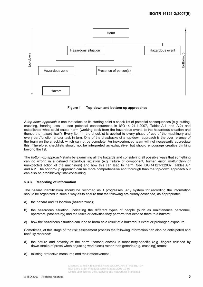
Various methods for structured hazard identification are available. In general, most follow one of the two approaches described below (see Figure 1):
Licensed to RISK ENGINEERING GCCH/CHRISTINE BLACHISO Store order #:868106/Downloaded:2007-12-05Single user licence only, copying and networking prohibited
ISO/TR 14121-2:2007(E)
© ISO 2007 – All rights reserved 5
Figure 1 — Top-down and bottom-up approaches
A top-down approach is one that takes as its starting point a check-list of potential consequences (e.g. cutting, crushing, hearing loss — see potential consequences in ISO 14121-1:2007, Tables A.1 and A.2) and establishes what could cause harm (working back from the hazardous event, to the hazardous situation and thence the hazard itself). Every item in the checklist is applied to every phase of use of the machinery and every part/function and/or task in turn. One of the drawbacks of a top-down approach is the over reliance of the team on the checklist, which cannot be complete. An inexperienced team will not necessarily appreciate this. Therefore, checklists should not be interpreted as exhaustive, but should encourage creative thinking beyond the list.
The bottom-up approach starts by examining all the hazards and considering all possible ways that something can go wrong in a defined hazardous situation (e.g. failure of component, human error, malfunction or unexpected action of the machinery) and how this can lead to harm. See ISO 14121-1:2007, Tables A.1 and A.2. The bottom-up approach can be more comprehensive and thorough than the top-down approach but can also be prohibitively time-consuming.
5.3.3 Recording of information
The hazard identification should be recorded as it progresses. Any system for recording the information should be organized in such a way as to ensure that the following are clearly described, as appropriate:
a) the hazard and its location (hazard zone);
b) the hazardous situation, indicating the different types of people (such as maintenance personnel, operators, passers-by) and the tasks or activities they perform that expose them to a hazard;
c) how the hazardous situation can lead to harm as a result of a hazardous event or prolonged exposure.
Sometimes, at this stage of the risk assessment process the following information can also be anticipated and usefully recorded:
d) the nature and severity of the harm (consequences) in machinery-specific (e.g. fingers crushed by down-stroke of press when adjusting workpiece) rather than generic (e.g. crushing) terms;
e) existing protective measures and their effectiveness.
Licensed to RISK ENGINEERING GCCH/CHRISTINE BLACHISO Store order #:868106/Downloaded:2007-12-05Single user licence only, copying and networking prohibited
ISO/TR 14121-2:2007(E)
6 © ISO 2007 – All rights reserved
5.3.4 Creative thinking
Detailed considerations of probabilities, severity of consequences or design of protective measures discourage creative thinking at this phase of the risk assessment process. This should be done later during risk estimation, evaluation and reduction.
5.3.5 Example of a tool for hazard identification
For more detail of application in practice, see the worked example in A.2.
5.4 Risk estimation
NOTE See ISO 14121-1:2007, Clause 7.
5.4.1 General
By definition, the two main elements of risk are severity of harm and the probability of occurrence of that severity of harm. The purpose of risk estimation (see ISO 14121-1:2007, Figure 2) is to determine the highest risk arising from each hazardous situation or accident scenario. The estimated risk is generally expressed as a level, index or score.
There are many different approaches to risk estimation, ranging from the simple qualitative to the detailed quantitative. The essential features of these different approaches are described below.
5.4.2 Severity of harm
NOTE 1 See ISO 14121-1:2007, 7.2.2.
Each hazardous event has the potential to result in several different severities of harm. However, in general, tools use only one entry for the severity of the potential harm for each hazard, so that the analyst(s) will have to choose the one that gives the highest risk. It is important to consider the worst severity of harm that can realistically occur. However, the probability of the worst credible severity of harm can be several orders of magnitude lower than the probability of a more realistic but lower severity of harm.
Moreover, choosing just one severity of harm to be considered is not always easy. The most severe can be very improbable and the most probable inconsequential, so that using either will lead to an inappropriate estimation of risk. For example, it is almost always credible that death will be the worst severity of harm: a simple cut can kill if it becomes septic or severs an artery; nevertheless, despite the probability of a cut being high, death is usually a remote probability. It can therefore be helpful to estimate the risk of a range of representative severities and use the one that gives the highest risk.
NOTE 2 In general, the lower the energy of the hazard, the lower the severity of the related potential harm. The severity of potential harm can also be related to the part of the body that is exposed, e.g. a hazard that can cause crushing injuries is generally fatal if the whole body or head is exposed.
For examples of different ways of classifying severity, see the risk estimation approaches described in Annex B.
5.4.3 Probability of occurrence of harm
NOTE See ISO 14121-1:2007, 7.2.3.
5.4.3.1 General
All approaches to risk estimation should require the estimation of the probability of an occurrence of harm by considering
a) exposure of person(s) to the hazard (see ISO 14121-1:2007, 7.2.3.2), Licensed to RISK ENGINEERING GCCH/CHRISTINE BLACHISO Store order #:868106/Downloaded:2007-12-05Single user licence only, copying and networking prohibited
ISO/TR 14121-2:2007(E)
© ISO 2007 – All rights reserved 7
b) probability of occurrence of a hazardous event (see ISO 14121-1:2007, 7.2.3.3), and
c) technical and human possibilities to avoid or limit the harm (see ISO 14121-1:2007, 7.2.3.4).
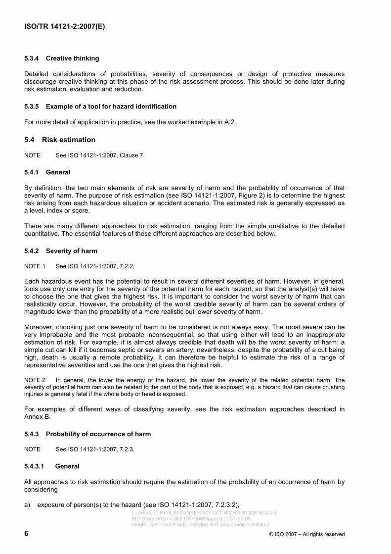
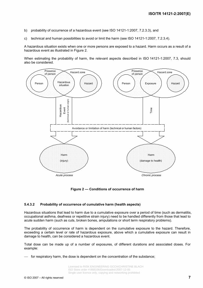
A hazardous situation exists when one or more persons are exposed to a hazard. Harm occurs as a result of a hazardous event as illustrated in Figure 2.
When estimating the probability of harm, the relevant aspects described in ISO 14121-1:2007, 7.3, should also be considered.
Figure 2 — Conditions of occurrence of harm
5.4.3.2 Probability of occurrence of cumulative harm (health aspects)
Hazardous situations that lead to harm due to a cumulative exposure over a period of time (such as dermatitis, occupational asthma, deafness or repetitive strain injury) need to be handled differently from those that lead to acute sudden harm (such as cuts, broken bones, amputations or short term respiratory problems).
The probability of occurrence of harm is dependent on the cumulative exposure to the hazard. Therefore, exceeding a certain level or rate of hazardous exposure, above which a cumulative exposure can result in damage to health, can be considered a hazardous event.
Total dose can be made up of a number of exposures, of different durations and associated doses. For example:
⎯ for respiratory harm, the dose is dependent on the concentration of the substance;
Licensed to RISK ENGINEERING GCCH/CHRISTINE BLACHISO Store order #:868106/Downloaded:2007-12-05Single user licence only, copying and networking prohibited

ISO/TR 14121-2:2007(E)
8 © ISO 2007 – All rights reserved
⎯ for hearing loss, it is dependent on the noise levels;
⎯ for repetitive strain injuries, it is dependent on the strain involved and the repetitiveness of the action.
The difference between harm caused suddenly and harm caused by prolonged exposure can be illustrated by two different causes of lower back injury. The first can be caused immediately on picking up a load that is too heavy. The second can be caused by repeatedly handling relatively light loads.
5.4.4 Risk estimation tools
5.4.4.1 General
In order to support a risk estimation process, a risk estimation tool can be selected and used. Most of the available risk estimation tools use one of the following methods:
⎯ risk matrix;
⎯ risk graph;
⎯ numerical scoring;
⎯ quantified risk estimation.
There are also hybrid tools that use a combination of methods.
The choice of a specific risk estimation tool is less important than the process itself. The benefit of risk assessment comes from the discipline of the process rather than in the absolute precision of the results, as long as all the elements of risk according to ISO 14121-1:2007, 7.2 are fully considered. Moreover, resources are better directed at risk reduction efforts rather than towards an attempt to achieve absolute precision in risk estimation.
Any risk estimation tool, either qualitative or quantitative, should deal with at least two parameters representing the elements of risk. One of these parameters is severity of harm (see 5.4.2); though in relation to some tools, this is referred to as the frequency or likelihood of that harm. The other parameter is the probability of occurrence of that harm (see 5.4.3).
Some tools or methods break the two elements down into parameters such as exposure, probability of occurrence of the hazardous event and the individual's possibility to avoid or limit the harm (see ISO 14121-1:2007, 7.2).
For a specific risk estimation tool, one class for each parameter is chosen that best corresponds to the hazardous situation/hazardous event (i.e. accident scenario). The chosen classes are then combined, using simple arithmetic, tables, charts or diagrams in order to estimate the risk.
Quantitative tools are used to estimate the frequency (e.g. per year) or probability (over a specified time period) of the occurrence of a specific severity of harm.
Generally, designers can only establish that risk has been reduced as far as practicable or that the objectives of risk reduction have been achieved.
5.4.4.2 Risk matrices
A risk matrix is a multidimensional table allowing the combination of any class of severity of harm (see 5.4.2) with any class of probability of occurrence of that harm (see 5.4.3). The more common matrices are two-dimensional but a matrix can have as many as four dimensions.
Licensed to RISK ENGINEERING GCCH/CHRISTINE BLACHISO Store order #:868106/Downloaded:2007-12-05Single user licence only, copying and networking prohibited

ISO/TR 14121-2:2007(E)
© ISO 2007 – All rights reserved 9
The use of a risk matrix is simple. For each hazardous situation that has been identified, one class for each parameter is selected on the basis of the definitions given. The content of the cell where the columns and rows corresponding to each selected class intersect gives the estimated risk level for the identified hazardous situation. This can be expressed as an index (e.g. from 1 to 6, or A to D) or a qualitative term such as “low”, “medium”, “high”, or similar.
The number of cells can vary widely from very small (e.g. four cells) to quite large (e.g. 36 cells). Cells can be grouped to reduce the number of classifications of risk. A classification using too-few cells is not helpful when deciding whether protective measures provide adequate risk reduction. Too many cells can make the matrix confusing to use.
There are many different matrices for estimating risk. An example is given in A.3.
5.4.4.3 Risk graphs
A risk graph is based on a decision tree. Each node in the graph represents a parameter of risk (severity, probability of occurrence, etc.) and each branch from a node represents a class of the parameter (e.g. slight severity or serious severity).
For each hazardous situation, a class should be allocated to each parameter. The path on the risk graph is then followed from the starting point. At each joint, the path proceeds on the appropriate branch in accordance with the selected class. The final branch points to the level or index of risk associated with the combination of classes (branches) that have been chosen. The end result is a level or index of risk qualified by terms such as “high”, “medium”, “low” , a number, e.g. 1 to 6, or a letter, e.g. A to F.
Risk graphs are useful for illustrating the amount of risk reduction provided by a protective measure and by the parameter of risk it influences.
Risk graphs become very cumbersome and cluttered if there are more than two branches for more than one of the parameters of risk. For this reason, hybrid methods tend to combine a risk graph with a matrix for one of the parameters, see 5.4.4.6.
An example of a risk graph is given in A.4.
5.4.4.4 Numerical scoring
Numerical scoring tools have two to four parameters that are broken down into a number of classes in much the same way as risk matrices and risk graphs. However, different numerical values, which can range from 1 to 20, are associated with the classes instead of a qualitative term. A class is chosen for each parameter and the associated values (or scores) are then combined (e.g. by addition and/or multiplication) to give a numerical score for the estimated risk. In some instances, these assigned values are represented in table(s), so their use is very similar to that of a matrix (see 5.4.4.2).
Scoring systems allow parameters to be easily and explicitly weighted. The use of numbers can give an impression of objectivity in the risk level even though the allocation of scores for each element of risk is highly subjective. However, this can be counteracted by grouping the scores into qualitative classifications of risk such as high, medium and low.
There are many different numerical scoring tools used to estimate risk. An example is given in A.5.
5.4.4.5 Quantified risk estimation
All the above methods are qualitative in nature. Although numbers are used with some tools and others express risk levels numerically, their nature is essentially qualitative. There are no common reference data and a numerical risk level estimated using one tool cannot directly be compared to one estimated using another.
Quantified risk estimation consists of the mathematical calculation, as accurately as possible with the data available, of the probability of a specific outcome occurring during a specific duration of time. Risk is often expressed as the annual frequency of the death of an individual. Quantified risk estimation allows the
Licensed to RISK ENGINEERING GCCH/CHRISTINE BLACHISO Store order #:868106/Downloaded:2007-12-05Single user licence only, copying and networking prohibited
ISO/TR 14121-2:2007(E)
10 © ISO 2007 – All rights reserved
calculated risk to be compared with criteria that can be related back to an actual number of deaths per year or accident statistics. It allows risk reduction measures to be evaluated in terms of by how much they reduce the risk so that the most cost-effective solution can be chosen. Unlike qualitative methods that estimate the risk from each hazardous situation separately, quantified risk estimation is generally used to estimate the total risk from all sources to an individual.
At the time of writing this part of ISO 14121, health statistics reports provide quantified estimates of risk for machine-related harm in a very generalized way. Typically, these sources give information on total injuries on a machine type over a specific period of time. However, if performed correctly, quantified risk estimation ensures a very comprehensive analysis leading to a clear understanding of exactly how a hazardous situation can develop leading to harm. This can generate more ideas for risk reduction options, and ensure that protective measures are selected with a full understanding of how harm can occur. Quantified risk estimation also allows for numerical risk comparisons to be made between one protective measure and another when all other variables are equal.
Quantified risk estimation is very resource-intensive and requires considerable skill to be conducted successfully. It requires a detailed and comprehensive model of the chain of events that lead to the defined outcome and is dependent on the quality of data for base events such as the failure of a piece of equipment or the probability of human error. Quantified risk estimation can be subjective and prone to error.
The use of small numbers to express risk such as 1,54 × 10⁻⁴ can give the impression of high precision, whereas in fact there can be considerable uncertainty in the data that have been used to calculate the risk. This can be an order of magnitude or more, so that it is not sensible to express risk using more than one significant figure.
To reduce some of the burden of starting with a blank sheet of paper, and in order to improve consistency, eliminate some of the subjectivity and to reduce error, guided quantified risk estimation methods are available. An example of a guided quantified tool is given in A.6.
5.4.4.6 Hybrids
Hybrid tools exist that combine two of the approaches described above. Commonly, these are risk graphs that contain within them either matrices or scoring systems for one of the elements of risk. A certain amount of quantification can also be incorporated into any of the qualitative approaches, including by giving frequency ranges to probabilities or exposures. For example, something that is “likely” can be expressed as being once a year, and a “high” exposure can be specified as being hourly.
An example of a hybrid tool is given in A.7.
5.5 Risk evaluation
NOTE See ISO 14121-1:2007, Clause 8.
The objectives of risk evaluation are
⎯ to decide which, if any, hazardous situations require further risk reduction, and
⎯ to determine whether the required risk reduction has been achieved without introducing further hazards or increasing other risks.
Some hazardous situations can be recorded as being excluded from further consideration due to having an extremely low (trivial) risk. Those that pose a significant risk should be reduced in accordance with ISO 12100. For those hazardous situations that pose a high risk, a more detailed risk estimation can be useful.
If relevant machinery-specific or hazard-specific standards exist (e.g. IEC 60204-1, which deals with electrical hazards), part of the risk evaluation could consist of ensuring that compliance with the standard is achieved, taking into account any limitations of the protective measures relevant to the machinery being assessed.
Licensed to RISK ENGINEERING GCCH/CHRISTINE BLACHISO Store order #:868106/Downloaded:2007-12-05Single user licence only, copying and networking prohibited

ISO/TR 14121-2:2007(E)
© ISO 2007 – All rights reserved 11
As part of the process of risk evaluation, the risks associated with the machinery or parts of the machinery can be compared with relevant International Standards.
For example:
⎯ risk reduction by inherently safe design, ISO 12100-2;
⎯ safeguarding of electrical equipment, IEC 60204-1;
⎯ control circuit architecture, ISO 13849-1;
⎯ safety reach distances, ISO 13852;
⎯ temperatures of touchable surfaces, ISO 13732-1;
⎯ machine-specific standards, e.g. textile machinery series ISO 11111.
As a general rule, the estimated risk is only one input to the decision to stop the iterative process of risk reduction. This decision should include other considerations such as regulations, laws, work organization and practices, technical limits and economics. See ISO 14121-1:2007, 8.2.
Care should be taken that simple and effective measures for reducing relatively low risks are not overlooked due to an exclusive focus on the highest risks.
6 Risk reduction
NOTE See ISO 14121-1:2007, 8.2 and ISO 12100-2.
6.1 General
Risk reduction is achieved by implementing protective measures in accordance with ISO 12100 by incorporating recommendations developed during risk assessment. During risk reduction, decisions are made regarding what needs to be done, by whom, when and at what cost.
The relative effectiveness of various protective measures to reduce risk is illustrated in Table 1, which describes the decision process (see also ISO 12100-1:2003, 5.4).
Table 1 — Effectiveness of various protective measures to reduce risk
Preferred action Priority a Alternative
Elimination of the hazard 1 Reduction of the severity of the possible harm related to the hazard
Elimination of the hazardous situation, i.e. exposure of the person to the hazard
2 Reduction of the frequency and/or duration of exposure
Elimination of possible hazardous events 3 Reduction in the probability of occurrence of possible hazardous events
Implementation of means to avoid harm 4 Implementation of means to limit harm
a 1 is the highest priority.
Different types of protective measure, in order of effectiveness, are given below. Explanations are provided as to their influence on the reduction of a particular risk element.
NOTE This information is provided for illustrative purposes only. It is not comprehensive. For more information, see ISO 12100-2.
Licensed to RISK ENGINEERING GCCH/CHRISTINE BLACHISO Store order #:868106/Downloaded:2007-12-05Single user licence only, copying and networking prohibited
ISO/TR 14121-2:2007(E)
12 © ISO 2007 – All rights reserved
6.2 Elimination of hazards by design
NOTE See ISO 12100-1:2003, Clause 4.
The first step in the risk reduction process is the elimination of the hazard by design. Eliminating hazards by design is the most effective method for reducing risk because it removes the source of harm. The following are examples of methods for elimination of the hazard:
⎯ substitution of hazardous materials and substances;
⎯ modification of physical features (e.g. elimination of sharp edges and shear points);
⎯ elimination of repetitive activities and harmful postures.
6.3 Risk reduction by design
If hazards cannot be eliminated by design, risk should be reduced by means of design features or the individual's interaction with the machine itself.
Examples of methods for risk reduction by design whose greatest effect is on the severity of harm are:
⎯ reducing energy (e.g. smaller force, lower hydraulic/pneumatic pressure, reduced working height, reduced speed);
⎯ utilizing technical safety equipment to prevent/reduce a hazard (e.g. a ventilation system prevents explosions/reduces hazardous vapours).
Examples of methods for risk reduction by design whose greatest effect is on exposure to the hazard are:
⎯ reducing the need to be in a hazardous situation (limiting exposure to hazards through mechanization or automation of loading/unloading or feeding/removal operations; location of the setting and maintenance points outside of danger zones);
⎯ relocating the source(s) of harm.
Examples of methods for risk reduction by design whose greatest effect is on the occurrence of hazardous event(s) are:
⎯ improving of reliability of components of the machine (mechanical, electrical/electronic, hydraulic/pneumatic components);
⎯ applying safe design measures to safety related parts of control systems (basic safety principles, well-tried safety principles and/or components, redundancy).
6.4 Safeguarding
If hazards cannot be eliminated or risks reduced adequately by design measures, safeguarding (guards and protective measures) should be applied that result in restricting exposure to hazards, lowering the probability of the hazardous event, or improving the possibility of avoiding or limiting harm.
When risk is reduced with the use of safeguards such as those listed under a) and b) below, there is little, if any, impact on the severity of harm. The greatest impact is on exposure (as long as the guard is being used as intended and is functioning properly) (see ISO 12100-2:2003, 5.2 to 5.4):
a) fixed guards, fencing or enclosures for the prevention of access to hazard zones;
b) interlocking guards preventing access to hazardous areas (e.g. interlocks with or without guard locking, interlock keys).
Licensed to RISK ENGINEERING GCCH/CHRISTINE BLACHISO Store order #:868106/Downloaded:2007-12-05Single user licence only, copying and networking prohibited
ISO/TR 14121-2:2007(E)
© ISO 2007 – All rights reserved 13
When risk is reduced with the use of safeguards such as those listed under c), d) and e) below, there is little, if any, impact on the severity of harm. The greatest impact is on the occurrence of a hazardous event, with little impact on exposure:
c) sensitive protective equipment (SPE) for the detection of persons entering into, or present in, the hazard zone (e.g. light curtains, pressure sensitive mats);
d) devices associated with safety-related functions of the control system of the machine (e.g. enabling device, limited movement control device, hold-to-run control device);
e) limiting devices (e.g. overloading and moment limiting devices, devices for limiting pressure or temperature, over-speed switches, devices for monitoring emissions).
6.5 Complementary protective measures
When design measures or safeguarding do not meet risk reduction objectives, complementary protective measures can be utilized to achieve further risk reduction. Examples of complementary protective measures whose greatest effect is on the ability to avoid or limit harm are:
⎯ emergency stop (see ISO 12100-2:2003, 5.5.2);
⎯ measures for the escape and rescue of trapped individuals (see ISO 12100-2:2003, 5.5.3);
⎯ measures for safe access to machinery (see ISO 12100-2:2003, 5.5.6);
⎯ provisions for easy and safe handling of machines and their heavy component parts (see ISO 12100-2:2003, 4.8.3).
Complementary protective measures whose greatest effect is on exposure are measures for isolation and energy dissipation (e.g. isolation valves or switches, locking devices, mechanical blocks to prevent movement), for example.
6.6 Information for use
NOTE See ISO 12100-1:2003, Clause 6.
6.6.1 General
The supplier should warn the user in the information for use about the risks that remain after risk reduction by design and safeguarding.
Information for use includes the following:
⎯ information provided on the machine;
⎯ documentation provided with the machine.
6.6.2 Information provided on the machine
Information for use provided on the machine includes the following:
a) warning signs (pictograms);
b) markings and labels for safe use (e.g. maximum speed of rotating parts, maximum working load, guard adjustment data, colour code);
c) audible or visual signals (e.g. horns, bells, whistles, lights); Licensed to RISK ENGINEERING GCCH/CHRISTINE BLACHISO Store order #:868106/Downloaded:2007-12-05Single user licence only, copying and networking prohibited

ISO/TR 14121-2:2007(E)
14 © ISO 2007 – All rights reserved
d) other warning devices (e.g. awareness barriers, vibration).
Information for use only impacts the ability to avoid the harm.
6.6.3 Documentation provided with the machine
Documentation provided with the machine includes the following:
a) instruction handbooks;
b) technical data sheets.
6.7 Training
The supplier should give details in the instruction handbook of any training necessary to ensure that individuals know how to correctly use the machinery and apply any protective measure. Training and competency is most important when the effectiveness of the protective measure depends on human behaviour. Training should include, but not be limited to, the following:
⎯ information for use provided with the machinery;
⎯ information for use developed by the user;
⎯ specialized training provided by the supplier, if available;
⎯ specialized training provided by the user.
Regular review and checking of the effectiveness of training can be necessary to ensure its long-term effectiveness. Training and enforcement of correct behaviour is also essential. Training mainly has an impact on the ability of individuals to avoid harm and can also reduce exposure and the probability of the occurrence of a hazardous event.
6.8 Personal protective equipment
The supplier should give details in the instruction handbook of any personal protective equipment to be used to protect individuals from the hazards associated with the residual risk. Examples of common uses of personal protective equipment are:
⎯ hearing protection;
⎯ safety glasses/goggles;
⎯ face shields;
⎯ respirators;
⎯ gloves;
⎯ protective clothing (e.g. resistant to heat, chemical splashes, cutting);
⎯ hard hat.
The reliability and maintenance of the personal protective equipment is very important for ensuring its long-term efficiency. Training and enforcement of correct use is also essential. The selection of any personal protective equipment should be made carefully, preferably in consultation with the person(s) to be protected, taking into consideration their needs in terms of protection, comfort, duration and frequency of use, and ability to follow their working methods, etc.
Personal protective equipment impacts the ability to avoid or limit harm. Licensed to RISK ENGINEERING GCCH/CHRISTINE BLACHISO Store order #:868106/Downloaded:2007-12-05Single user licence only, copying and networking prohibited

ISO/TR 14121-2:2007(E)
© ISO 2007 – All rights reserved 15
6.9 Standard operating procedures
The supplier should give details in the instruction handbook of any standard operating procedures (SOP) that the user is to adopt in order to operate or maintain the machine. These procedures could include the following:
⎯ work planning and organization;
⎯ clarification/harmonization of tasks, authority, responsibilities;
⎯ supervision;
⎯ lock-out procedures;
⎯ safe operating methods and procedures.
NOTE When risk reduction is provided by organizational measures, it is important to ensure, as far as possible, that they are followed and cannot be circumvented.
7 Risk assessment iteration
NOTE See ISO 12100-1:2003, 5.5.
Once protective measures have been incorporated, in order to reduce risk, all stages of risk assessment should be repeated to check whether:
⎯ there are any changes to the limits of the machinery;
⎯ any new hazards or hazardous situations have been introduced;
⎯ risks from any existing hazardous situations have been increased;
⎯ the protective measures reduce risk sufficiently;
⎯ any additional protective measures are required;
⎯ risk reduction objectives have been achieved.
Risk assessment iteration should be carried out taking into account the reliability, ease of use, possibility of defeating or circumventing the protective measures, and the ability to maintain them in accordance with ISO 14121-1:2007, 7.3.5, 7.3.6 and 7.3.7. Consideration should be given to the possibility of persons taking the protective measure for granted and not being prepared should it fail. This is particularly relevant for interlocks and light curtains.
8 Documentation of the risk assessment
NOTE See ISO 14121-1:2007, Clause 9.
Written records of all risk assessments should be made and retained. These should not be confused with the information for use of the machine provided by the supplier to the user. However, the risk assessment documentation can be a useful reference when writing the information for use.
It is important that the process be properly documented in order to allow examination of decisions at a later date by others who have not been directly involved in the risk assessment. This documentation should record the results of the assessment in accordance with ISO 14121-1:2007, Clause 9. It should include a description of the method(s) and tool(s) that have been used to conduct the assessment and copies of completed record sheets. Figures (photographs, diagrams, drawings, etc.) of the machinery including hazard zones, hazards and applied protective measures are useful.
Licensed to RISK ENGINEERING GCCH/CHRISTINE BLACHISO Store order #:868106/Downloaded:2007-12-05Single user licence only, copying and networking prohibited

ISO/TR 14121-2:2007(E)
16 © ISO 2007 – All rights reserved
When documenting protective measures that have been implemented, a description of those measures that are needed to ensure that they remain effective should be included (e.g. maintenance, periodic user inspection).
See Annex B for an example of a risk assessment and the risk reduction process.
Licensed to RISK ENGINEERING GCCH/CHRISTINE BLACHISO Store order #:868106/Downloaded:2007-12-05Single user licence only, copying and networking prohibited

ISO/TR 14121-2:2007(E)
© ISO 2007 – All rights reserved 17
Annex A (informative)
Examples of methods for several steps of the risk assessment process
A.1 General
This annex includes examples of methods that can be applied during the risk assessment process. They are not the only tools available and their inclusion in this part of ISO 14121 does not indicate that they are approved or recommended above any others that are in accordance with ISO 14121-1.
These examples do not cover all possible situations, as actual situations vary from facility to facility. The choice made by the individuals performing the risk assessment is influenced by many different factors and can lead to different results.
These examples are provided to illustrate to the user of this part of ISO 14121 how an actual hazard identification or a risk estimation can look when a particular method is selected.
The examples given are for the following:
a) hazard identification by application of forms (see A.2);
b) risk matrices (see A.3);
c) risk graphs (see A.4);
d) numerical scoring (see A.5);
e) quantified risk estimation (see A.6);
f) hybrids (see A.7).
For particular hazards related to long-term harm (e.g. those generated by noise, materials and substances, vibration, radiation or related to ergonomics) or with very high effects (e.g. fire or an explosion), it could be appropriate to take into account specific risk estimation methods.
Risk assessments are not scientific exercises; therefore, resources are best spent on risk reduction efforts rather than the optimizing of risk ratings.
NOTE These examples only illustrate how such methods/tools could look and be used. They are not a comprehensive user guide to fully developed methods.
A.2 Hazard identification by application of forms
A.2.1 General
The aim of this clause is to show a method for hazard identification (see 5.3 and ISO 14121-1:2007, Clause 6) using as the main tool the checklists defined in ISO 14121-1:2007, A.2 to A.4.
These checklists cannot be considered complete. They should rather be used as the starting point for identifying relevant hazards. Then, in order to ensure a more complete hazard identification, other sources such as regulations, standards and engineering knowledge should be taken into account.
This method can be complemented with other methods based on, for example, brainstorming, comparison with similar machinery, review of data about accidents and/or incidents involving similar machinery.
Licensed to RISK ENGINEERING GCCH/CHRISTINE BLACHISO Store order #:868106/Downloaded:2007-12-05Single user licence only, copying and networking prohibited
ISO/TR 14121-2:2007(E)
18 © ISO 2007 – All rights reserved
The method will be more effective the more complete and detailed the available information for risk assessment (see ISO 14121-1:2007, 4.2) and the determination of the limits of the machinery (see 5.2 and ISO 14121-1:2007, Clause 5).
The method is applicable to any phase of the machine life cycle.
A.2.2 Description of the tool or method
Taking into account the limits of the machine, the first step is to determine the extent of the system to be analysed, e.g. the phase(s) of the machine life cycle, the part(s) and/or function(s) of the machine.
The second step is to define the tasks to be performed by people interacting with or near the machine, or the operations to be performed by the machine, in each of the selected phases. In this step, the list of tasks detailed in ISO 14121-1:2007, Table A.3, could be used.
The third step is to examine, for each task or operation in each particular hazard zone, the relevant hazards and the possible accident scenarios. This can be done by using either a top-down approach, if the starting point is the potential consequence (harm), or a bottom-up approach, if the starting point is the origin of the hazard. In this step, use ISO 14121-1:2007, Table A.1, for the description of origins of hazards, ISO 14121-1:2007, Table A.3, for the description of hazardous situations, and ISO 14121-1:2007, Table A.4, for the description of hazardous events.
A.2.3 Documentation
The form given as Table A.1 can be used to document the results of this hazard identification.
A.2.4 Application
A.2.4.1 General
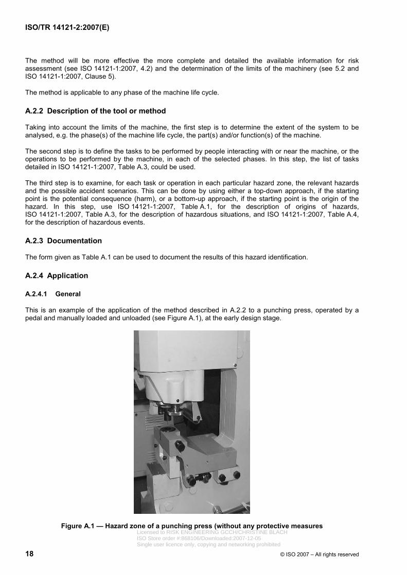
This is an example of the application of the method described in A.2.2 to a punching press, operated by a pedal and manually loaded and unloaded (see Figure A.1), at the early design stage.
Figure A.1 — Hazard zone of a punching press (without any protective measures Licensed to RISK ENGINEERING GCCH/CHRISTINE BLACHISO Store order #:868106/Downloaded:2007-12-05Single user licence only, copying and networking prohibited

© ISO 2007 – All rights reserved 19
Tabl
e A
.1 —
Exa
mpl
e of
a fo
rm fo
r haz
ard
iden
tific
atio
n
Haz
ard
iden
tific
atio
n
Mac
hine
(ide
ntifi
catio
n)
M
etho
d/to
ol
Ana
lyst
Sour
ces
(e.g
. pre
limin
ary
desi
gn d
ocum
enta
tion,
te
chni
cal f
ile, c
onst
ruct
ion
file)
Cur
rent
ver
sion
D
ate
Ex
tent
(e.g
. — p
hase
of t
he li
fe c
ycle
, —
par
t/fun
ctio
n of
the
mac
hine
)
Acc
iden
t sce
nario
R
ef. n
o.
Haz
ard
zone
Ta
sk/o
pera
tion
(ISO
141
21-1
:200
7, T
able
A.3
)H
azar
d (IS
O 1
4121
-1:2
007,
Tab
le A
.1)
Haz
ardo
us s
ituat
ion
(ISO
141
21-1
:200
7, T
able
A.3
) H
azar
dous
eve
nt
(ISO
141
21-1
:200
7, T
able
A.4
)
1
2
3
4
5
6
7
8
9
10
ISO/TR 14121-2:2007(E)
Licensed to RISK ENGINEERING GCCH/CHRISTINE BLACHISO Store order #:868106/Downloaded:2007-12-05Single user licence only, copying and networking prohibited
ISO/TR 14121-2:2007(E)
20 © ISO 2007 – All rights reserved
A.2.4.2 Extent of the system to be analysed
This example deals only with the hazard identification related to the operation phase of the machine at the hazard zone. It does not cover other phases of the life cycle of the machine, such as assembly, setting, maintenance or fault finding (see ISO 14121-1:2007, Table A.3).
A.2.4.3 Tasks/operations to be performed
During the operation phase of the punching press the following tasks are performed:
a) manual loading and unloading of workpieces;
b) positioning of workpieces;
c) holding of workpieces during punching;
d) minor interventions (remove waste materials and lubrication of the tool).
A.2.4.4 Relevant hazards and accident scenarios
For each of the defined tasks, by using the “hazards” column of ISO 14121-1:2007, Table A.1, and applying a bottom-up approach, all the possible origins of hazards are checked and those that are relevant are identified. For each relevant hazard, all combinations of hazardous situations and hazardous events are examined using the lists given ISO 14121-1:2007, Tables A.3 and A.4.
A.2.4.5 Results of the hazard identification
The results of the first step of this examination are documented in Table A.2.
Licensed to RISK ENGINEERING GCCH/CHRISTINE BLACHISO Store order #:868106/Downloaded:2007-12-05Single user licence only, copying and networking prohibited

© ISO 2007 – All rights reserved 21
Tabl
e A
.2 —
Exa
mpl
e of
a c
ompl
eted
form
for h
azar
d id
entif
icat
ion
Haz
ard
iden
tific
atio
n M
achi
ne
Pun
chin
g pr
ess
Met
hod/
tool
C
heck
lists
— IS
O 1
4121
-1:2
007,
Ann
ex A
Ana
lyst
<N
ame>
So
urce
s P
relim
inar
y de
sign
doc
umen
tatio
n
Cur
rent
ver
sion
V
1
Ope
ratio
n D
ate
20/0
5/05
Ex
tent
(e
.g. —
pha
se o
f the
life
cyc
le,
— p
art/f
unct
ion
of th
e m
achi
ne)
Pun
chin
g fu
nctio
n
Acc
iden
t sce
nario
R
ef.
no.
Haz
ard
zone
Ta
sk/o
pera
tion
Haz
ard
Haz
ardo
us s
ituat
ion
Haz
ardo
us e
vent
1 Fa
lling
obje
cts
(wor
kpie
ces)
C
rush
ing
(foot
or f
inge
rs)
Han
dlin
g he
avy
wor
kpie
ces
with
bo
th h
ands
Fa
lling
of a
wor
kpie
ce
2
Man
ual l
oadi
ng/u
nloa
ding
an
d po
sitio
ning
of t
he
wor
kpie
ce
Sha
rp e
dges
(wor
kpie
ces)
C
uttin
g H
andl
ing
wor
kpie
ces
with
sha
rp
edge
s w
ith b
oth
hand
s C
onta
ct w
ith s
harp
edg
es a
nd c
orne
rs
of w
orkp
iece
s
3
Mov
ing
elem
ents
(dow
nwar
d an
d up
war
d m
ovem
ent o
f the
pun
ch a
nd u
pwar
d m
ovem
ent o
f the
wor
kpie
ce)
Cru
shin
g, s
ever
ing
and
punc
ture
Wor
k ne
ar m
ovin
g pa
rts
Acc
ess
to c
onta
ct w
ith m
ovin
g pa
rts d
ue
to a
n ab
senc
e of
gua
rd o
r pr
otec
tive
devi
ce
4
Mov
ing
elem
ents
(eje
ctio
n of
tool
par
ts o
r w
orkp
iece
par
ts)
Impa
ct
Ope
rato
r and
oth
er p
eopl
e ex
pose
d to
eje
ctio
n of
par
ts
Bre
ak-u
p of
the
punc
h or
the
wor
kpie
ce
(by
seve
ral c
ause
s su
ch a
s in
adeq
uate
pu
nch,
pun
ch fa
tigue
or a
gein
g or
fra
gilit
y, in
adeq
uate
wor
kpie
ce m
ater
ial)
5 N
oisy
man
ufac
turin
g pr
oces
s (im
pact
noi
se)
Dis
com
fort
Ope
rato
r and
oth
er p
eopl
e ex
pose
d to
haz
ards
gen
erat
ed b
y no
ise
Em
issi
on o
f a le
vel o
f noi
se th
at c
an b
e ha
zard
ous
6
Man
ual h
oldi
ng o
f the
w
orkp
iece
with
bot
h ha
nds
durin
g pu
nchi
ng
Par
ts w
hich
hav
e be
com
e liv
e un
der f
aulty
co
nditi
ons
Ele
ctric
sho
ck
Wor
k w
ith a
mac
hine
und
er v
olta
geIn
dire
ct c
onta
ct
7
Pun
ctur
ing
zone
Min
or i
nter
vent
ions
dur
ing
oper
atio
n (re
mov
ing
was
te
mat
eria
l an
d lu
bric
atio
n of
th
e to
ol)
Mov
ing
elem
ents
(dow
nwar
d an
d up
war
d m
ovem
ent o
f the
pun
ch u
nd u
pwar
d m
ovem
ent o
f the
wor
kpie
ce)
Cru
shin
g, s
ever
ing
and
punc
ture
Wor
k un
der p
ower
ed a
ctua
tors
(c
ylin
der-
tool
) H
uman
er
rors
in
th
e w
ork
proc
edur
e (u
se a
clo
th in
stea
d of
a c
onta
iner
with
a
long
ne
ck/s
pout
fo
r m
anua
l to
ol
lubr
icat
ion)
and
une
xpec
ted/
unin
tend
ed
star
t-up
ISO/TR 14121-2:2007(E)
Licensed to RISK ENGINEERING GCCH/CHRISTINE BLACHISO Store order #:868106/Downloaded:2007-12-05Single user licence only, copying and networking prohibited

ISO/TR 14121-2:2007(E)
22 © ISO 2007 – All rights reserved
A.3 Risk assessment using a risk matrix
A.3.1 General
The risk matrix is applied after hazards have been identified (see ISO 14121-1:2007, Clause 6) and is used to assess risks associated with the identified hazards (see ISO 14121-1:2007, Clauses 7 and 8). A risk matrix can be used to assess risks of machinery, equipment, facilities or other situations in many industries.
The primary use of a risk matrix is to help identify risks that are unacceptably high so that risk reduction efforts can focus on these areas. The risk matrix is basically used to rank or group risks into risk levels so that decisions can be made about risk acceptability.
A risk matrix approach provides a simple, quick and effective method to derive a risk level for a hazard. The risk matrix approach is subjective; it relies on the good judgement of the persons assessing the risk. Therefore, this approach works best with a team of persons who are knowledgeable of, and experienced in, the tasks and machinery/equipment/facility being assessed (see 4.2).
The risk matrix method excels in simplicity and speed in both learning and using. However, it does not provide great precision or repeatability due to the subjective nature of the method. Persons wanting greater precision in ratings may prefer other methods. Note that greater precision typically requires more time to learn and to complete, and can result in different risk reduction measures.
A.3.2 Description of the tool or method
A.3.2.1 General
There are four steps to the risk matrix approach as follows.
A.3.2.2 Selection of a risk matrix
Risk matrices have been used for many years, and many different variations exist. Two examples are shown in Tables A.3 and A.4, in which different risk matrices use different levels for each risk factor — for example, Table A.3 has four levels of probability whereas Table A.4 has six. Levels usually range from three to up to ten, with four or five being the most common.
Table A.3 — Risk estimation matrix according to ANSI B11 TR3:2000
Severity of harm Probability of occurrence of harm Catastrophic Serious Moderate Minor
Very likely high high high medium
Likely high high medium low
Unlikely medium medium low negligible
Remote low low negligible negligible
Table A.4 — Risk matrix according to IEC 61508
Consequences Frequency
Catastrophic Critical Marginal Negligible
Frequent I I I II Probable I I II III
Occasional I II III III
Remote II III III IV
Improbable III III IV IV
Incredible IV IV IV IV Licensed to RISK ENGINEERING GCCH/CHRISTINE BLACHISO Store order #:868106/Downloaded:2007-12-05Single user licence only, copying and networking prohibited
ISO/TR 14121-2:2007(E)
© ISO 2007 – All rights reserved 23
A.3.2.3 Assessment of severity
For each hazard or hazardous situation (task), the severity of harm or consequences that could result should be assessed. Historical data can be of great value as a baseline. Severity is often assessed as personal injury, although it can include other elements such as the following:
⎯ the number of fatalities, injuries or illnesses;
⎯ the value of property or equipment damaged;
⎯ the time for which productivity will be lost;
⎯ the extent of environmental damage;
⎯ other factors.
Assessing severity can be accomplished using the selected risk matrix. As an example, the severity levels in Table A.3:
⎯ catastrophic — death or permanent disabling injury or illness (unable to return to work);
⎯ serious — severe debilitating injury or illness (able to return to work at some point);
⎯ moderate — significant injury or illness requiring more than first aid (able to return to same job);
⎯ minor — no injury or slight injury requiring no more than first aid (little or no lost work time).
Assessing severity usually focuses on the worst credible consequence rather than the worst conceivable consequence.
A.3.2.4 Assessment of probability
For each hazard or hazardous situation (task), the probability of occurrence of harm should be assessed. Unless empirical data are available, which would be rare, the process of selecting the probability of an incident occurring will again be subjective. For this reason, brainstorming with knowledgeable people is advantageous.
When estimating probability, the highest credible level of probability should be selected. Estimating probability should include the following:
⎯ frequency and duration of exposure to a hazard;
⎯ personnel who perform the tasks;
⎯ machine/task history;
⎯ workplace environment;
⎯ human factors;
⎯ reliability of safety functions;
⎯ possibility to defeat or circumvent protective measures;
⎯ ability to maintain protective measures;
⎯ ability to avoid harm.
Licensed to RISK ENGINEERING GCCH/CHRISTINE BLACHISO Store order #:868106/Downloaded:2007-12-05Single user licence only, copying and networking prohibited

ISO/TR 14121-2:2007(E)
24 © ISO 2007 – All rights reserved
As with severity, there are many scales used to assess the probability of occurrence of harm. Some methods do not provide descriptions other than the terms used (see Table A.4). Other matrices provide additional descriptions as in Table A.3:
⎯ very likely — near certain to occur;
⎯ likely — can occur;
⎯ unlikely — not likely to occur;
⎯ remote — so unlikely as to be near zero.
In some methods, a distinction is drawn between probability and likelihood, where probability is a numerical value between 0 and 1 and likelihood a qualitative description of probability. However, many methods do not distinguish between probability and likelihood and use the two terms synonymously.
Probability should be related to an interval base of some sort, such as a unit of time or activity, events, units produced, or the life cycle of a facility, equipment, process or product. The unit of time can be the useful life of the machine.
A.3.2.5 Derivation of the risk level
Once the severity and probability are assessed, an initial risk level can be derived from the selected risk matrix. The risk matrix maps the risk factors to risk levels as shown in Tables A.3 and A.4
Using Table A.3 as an example, a “serious” severity and “likely” probability yields a “high” risk level. How the risk factors of severity and probability are combined varies with different risk matrices. The result of this evaluation will typically yield an array of low to high risks. Since the risk assessment process is usually subjective, the risk levels will also be subjective.
In many instances, the risk acceptability decision is left to the user, since the decision is culture-, situation- and/or time-dependent.
A.3.3 Application
A.3.3.1 Description of wood-working mill example
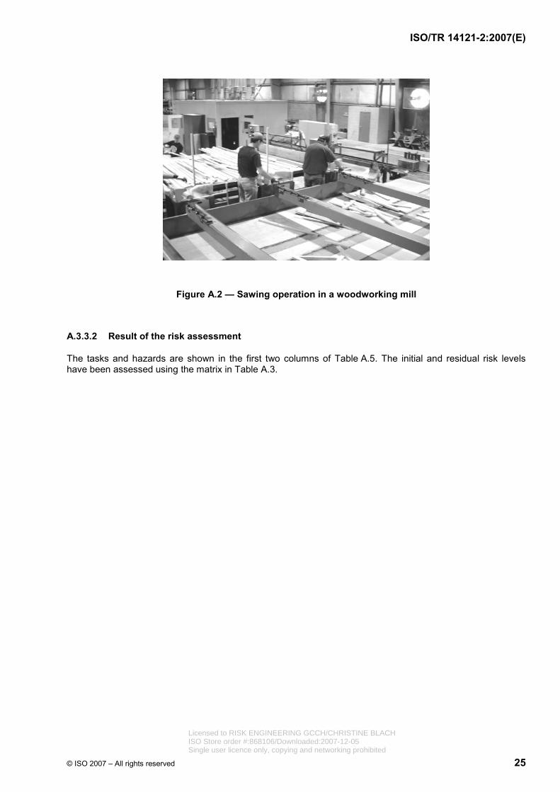
Figure A.2 shows a sawing operation in a woodworking mill. The sawyers pick up pieces of lumber from the conveyor on their left, cut out knots using a foot-activated jump saw, and place the cut boards on the conveyor on their right.
Licensed to RISK ENGINEERING GCCH/CHRISTINE BLACHISO Store order #:868106/Downloaded:2007-12-05Single user licence only, copying and networking prohibited
ISO/TR 14121-2:2007(E)
© ISO 2007 – All rights reserved 25
Figure A.2 — Sawing operation in a woodworking mill
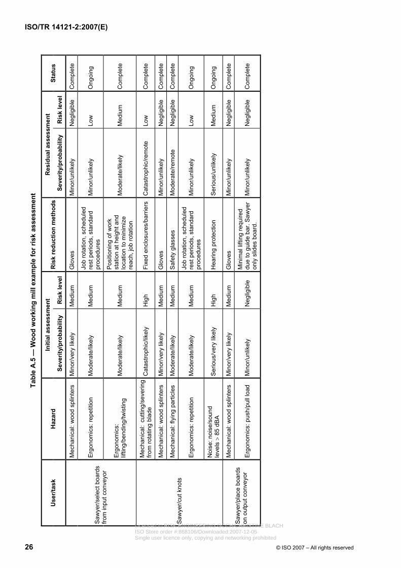
A.3.3.2 Result of the risk assessment
The tasks and hazards are shown in the first two columns of Table A.5. The initial and residual risk levels have been assessed using the matrix in Table A.3.
Licensed to RISK ENGINEERING GCCH/CHRISTINE BLACHISO Store order #:868106/Downloaded:2007-12-05Single user licence only, copying and networking prohibited
26 © ISO 2007 – All rights reserved
Tabl
e A
.5 —
Woo
d w
orki
ng m
ill e
xam
ple
for r
isk
asse
ssm
ent
Initi
al a
sses
smen
t R
esid
ual a
sses
smen
t U
ser/t
ask
Haz
ard
Seve
rity/
prob
abili
ty
Ris
k le
vel
Ris
k re
duct
ion
met
hods
Seve
rity/
prob
abili
ty
Ris
k le
vel
Stat
us
Mec
hani
cal:
woo
d sp
linte
rs
Min
or/v
ery
likel
y M
ediu
m
Glo
ves
Min
or/u
nlik
ely
Neg
ligib
le
Com
plet
e
Erg
onom
ics:
repe
titio
n M
oder
ate/
likel
y M
ediu
m
Job
rota
tion,
sch
edul
ed
rest
per
iods
, sta
ndar
d pr
oced
ures
M
inor
/unl
ikel
y Lo
w
Ong
oing
S
awye
r/sel
ect b
oard
s fro
m in
put c
onve
yor
Erg
onom
ics:
lif
ting/
bend
ing/
twis
ting
Mod
erat
e/lik
ely
Med
ium
Pos
ition
ing
of w
ork
stat
ion
at h
eigh
t and
lo
catio
n to
min
imiz
e re
ach,
job
rota
tion
Mod
erat
e/lik
ely
Med
ium
C
ompl
ete
Mec
hani
cal:
cutti
ng/s
ever
ing
from
rota
ting
blad
e C
atas
troph
ic/li
kely
H
igh
Fixe
d en
clos
ures
/bar
riers
Cat
astro
phic
/rem
ote
Low
C
ompl
ete
Mec
hani
cal:
woo
d sp
linte
rs
Min
or/v
ery
likel
y M
ediu
m
Glo
ves
M
inor
/unl
ikel
y N
eglig
ible
C
ompl
ete
Mec
hani
cal:
flyin
g pa
rticl
es
Mod
erat
e/lik
ely
Med
ium
S
afet
y gl
asse
s
Mod
erat
e/re
mot
e N
eglig
ible
C
ompl
ete
Erg
onom
ics:
repe
titio
n M
oder
ate/
likel
y M
ediu
m
Job
rota
tion,
sch
edul
ed
rest
per
iods
, sta
ndar
d pr
oced
ures
M
inor
/unl
ikel
y Lo
w
Ong
oing
Saw
yer/c
ut k
nots
Noi
se: n
oise
/sou
nd
leve
ls >
85
dBA
S
erio
us/v
ery
likel
y H
igh
Hea
ring
prot
ectio
n S
erio
us/u
nlik
ely
Med
ium
O
ngoi
ng
Mec
hani
cal:
woo
d sp
linte
rs
Min
or/v
ery
likel
y M
ediu
m
Glo
ves
M
inor
/unl
ikel
y N
eglig
ible
C
ompl
ete
Saw
yer/p
lace
boa
rds
on o
utpu
t con
veyo
r E
rgon
omic
s: p
ush/
pull
load
M
inor
/unl
ikel
y N
eglig
ible
M
inim
al li
fting
requ
ired
due
to g
uide
bar
. Saw
yer
only
slid
es b
oard
. M
inor
/unl
ikel
y N
eglig
ible
C
ompl
ete
ISO/TR 14121-2:2007(E)
Licensed to RISK ENGINEERING GCCH/CHRISTINE BLACHISO Store order #:868106/Downloaded:2007-12-05Single user licence only, copying and networking prohibited

ISO/TR 14121-2:2007(E)
© ISO 2007 – All rights reserved 27
A.3.3.3 Discussion
As shown in the example, the risk matrix method provides a simple and efficient means of assessing risk. The risk matrix can be applied to assess a single task on a specific machine, or for assessing the many tasks on an entire manufacturing process. The risk matrix method can also be used to assess consumer or industrial products.
The best approach for a particular company is to find the risk assessment method that works well in its organizational culture and design processes. Industry standards or guidelines should be considered a starting point. As long as any one risk assessment method is selected, validated, and adequately integrated into the organization, there is no “wrong” method.
A.4 Risk assessment using risk graph
A.4.1 General
This example is a method for hazard identification and risk estimation using a risk graph.
It is not the intention here to either explain in detail how the form is filled in nor to justify the way this tool has been developed. Training is required to become competent in the use of this method for risk assessment.
This example presents the application of the method to a paper trimmer press, already installed. Risk has been estimated twice: once before protective measures have been chosen and a second time after they have been implemented.
A.4.2 Description of the tool or method
Before the risk is estimated using the risk graph, the associated hazard, hazardous situation, hazardous event and possible harm is described in accordance with ISO 14121-1:2007, 5.3. A risk index is then calculated using the risk graph given in Figure A.3, based on the following four parameters, corresponding to the four elements of risk as defined in ISO 14121-1:2007, 7.2.1, and each having its particular limits.
⎯ Severity of harm: S
1) S1 slight injury (usually reversible), for example, scratches, laceration, bruising, light wound requiring first aid).
2) S2 serious injury (usually irreversible, including fatality), for example, broken or torn-out or crushed limbs, fractures, serious injuries requiring stitches, major musculoskeletal troubles (MST), fatalities.
⎯ Frequency and/or duration of exposure to hazard: F
1) F1 twice or less per work shift or less than 15 min cumulated exposure per work shift.
2) F2 more than twice per work shift or more than 15 min cumulated exposure per work shift.
⎯ Probability of occurrence of the hazardous event: O
1) O1 mature technology, proven and recognized in safety application; robustness.
2) O2 technical failure observed in the two last years:
⎯ inappropriate human action by a well-trained person aware of the risks and having more than six months experience on the work station.
Licensed to RISK ENGINEERING GCCH/CHRISTINE BLACHISO Store order #:868106/Downloaded:2007-12-05Single user licence only, copying and networking prohibited
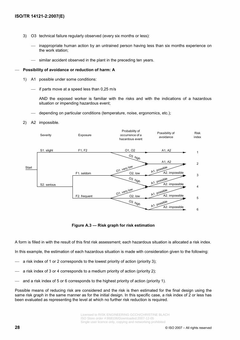
ISO/TR 14121-2:2007(E)
28 © ISO 2007 – All rights reserved
3) O3 technical failure regularly observed (every six months or less):
⎯ inappropriate human action by an untrained person having less than six months experience on the work station;
⎯ similar accident observed in the plant in the preceding ten years.
⎯ Possibility of avoidance or reduction of harm: A
1) A1 possible under some conditions:
⎯ if parts move at a speed less than 0,25 m/s
AND the exposed worker is familiar with the risks and with the indications of a hazardous situation or impending hazardous event;
⎯ depending on particular conditions (temperature, noise, ergonomics, etc.);
2) A2 impossible.
Figure A.3 — Risk graph for risk estimation
A form is filled in with the result of this first risk assessment; each hazardous situation is allocated a risk index.
In this example, the estimation of each hazardous situation is made with consideration given to the following:
⎯ a risk index of 1 or 2 corresponds to the lowest priority of action (priority 3);
⎯ a risk index of 3 or 4 corresponds to a medium priority of action (priority 2);
⎯ and a risk index of 5 or 6 corresponds to the highest priority of action (priority 1).
Possible means of reducing risk are considered and the risk is then estimated for the final design using the same risk graph in the same manner as for the initial design. In this specific case, a risk index of 2 or less has been evaluated as representing the level at which no further risk reduction is required.
Licensed to RISK ENGINEERING GCCH/CHRISTINE BLACHISO Store order #:868106/Downloaded:2007-12-05Single user licence only, copying and networking prohibited
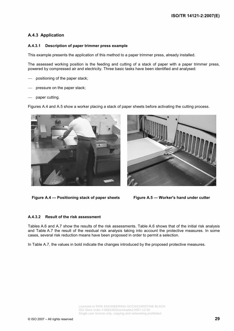
ISO/TR 14121-2:2007(E)
© ISO 2007 – All rights reserved 29
A.4.3 Application
A.4.3.1 Description of paper trimmer press example
This example presents the application of this method to a paper trimmer press, already installed.
The assessed working position is the feeding and cutting of a stack of paper with a paper trimmer press, powered by compressed air and electricity. Three basic tasks have been identified and analysed:
⎯ positioning of the paper stack;
⎯ pressure on the paper stack;
⎯ paper cutting.
Figures A.4 and A.5 show a worker placing a stack of paper sheets before activating the cutting process.
Figure A.4 — Positioning stack of paper sheets Figure A.5 — Worker's hand under cutter
A.4.3.2 Result of the risk assessment
Tables A.6 and A.7 show the results of the risk assessments. Table A.6 shows that of the initial risk analysis and Table A.7 the result of the residual risk analysis taking into account the protective measures. In some cases, several risk reduction means have been proposed in order to permit a selection.
In Table A.7, the values in bold indicate the changes introduced by the proposed protective measures.
Licensed to RISK ENGINEERING GCCH/CHRISTINE BLACHISO Store order #:868106/Downloaded:2007-12-05Single user licence only, copying and networking prohibited
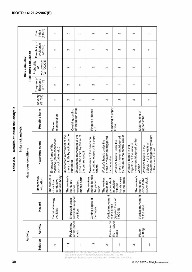
Tabl
e A
.6 —
Res
ults
of i
nitia
l ris
k an
alys
is
Initi
al ri
sk a
naly
sis
Act
ivity
H
azar
dous
con
ditio
ns
Ris
k es
timat
ion
Ris
k in
dex
calc
ulat
ion
Solu
tion
Act
ivity
H
azar
d H
azar
dous
si
tuat
ion
Haz
ardo
us e
vent
Po
ssib
le h
arm
S
ever
ity
(S1/
S2)
Freq
uenc
y/
Exp
osur
e (F
1/F2
)
Pro
babi
lity
of
occu
rren
ce
(O1/
O2/
O3)
Pos
sibi
lity
of
avoi
danc
e (A
1/A
2)
Ris
k in
dex
(1 to
6)
1 E
lect
rical
ene
rgy
avai
labl
e
The
wor
ker i
s cl
ose
to a
co
nduc
tive
met
allic
bod
y
Ene
rgiz
ed fr
ame
of th
e m
achi
ne (f
aile
d co
nnec
tion,
w
orn
out c
able
, etc
.)
Wor
ker
elec
trocu
tion
2 2
2 2
5
1.1
Une
xpec
ted
mov
emen
t of t
he
pres
s or
kni
fe b
y ac
tion
on th
e st
art p
edal
2
2 2
2 5
—
Ene
rgiz
ed p
ress
an
d kn
ife in
upp
er
posi
tion
The
wor
ker's
ha
nds
are
unde
r en
ergi
zed
mob
ile p
arts
U
nexp
ecte
d m
ovem
ent o
f the
pr
ess
or th
e kn
ife b
y fa
ilure
of
the
cont
rol c
ircui
t
Cru
shin
g, c
uttin
g of
the
uppe
r lim
bs2
2 2
2 5
1.2
Pos
ition
ing
of th
e pa
per
stac
k
Cut
ting
edge
s of
th
e pa
per
The
wor
kers
ha
nds
hand
le
the
pape
r st
ack
Mov
emen
ts o
f the
han
ds o
n th
e cu
tting
edg
es o
f the
pap
er
shee
ts
Fing
ers
or h
ands
cu
t 1
2 3
1 2
2 W
orke
r's h
ands
und
er th
e pr
ess
in m
ovem
ent t
rigge
red
by th
e w
orke
r 2
1 3
2 4
—
Pre
ssur
e on
th
e pa
per
stac
k
Ver
tical
mov
emen
t of
the
pres
s (a
pplie
d fo
rce
of
1 00
0 N
)
The
wor
ker
hold
s th
e pa
per s
tack
in
pos
ition
w
ith h
is
hand
s cl
ose
to th
e pr
ess
Wor
ker's
han
ds u
nder
the
pres
s in
mov
emen
t trig
gere
d by
failu
re o
f the
con
trol c
ircui
t
Cru
shin
g of
upp
er
limbs
2
1 2
2 3
3
Wor
ker's
han
ds in
the
traje
ctor
y of
the
knife
in
mov
emen
t trig
gere
d by
the
wor
ker
2 1
3 2
4
—
Pap
er
cutti
ng
Ver
tical
mov
emen
t of
the
knife
The
wor
ker's
ha
nds
are
clos
e to
the
pape
r sta
ck
Wor
ker's
han
ds in
the
traje
ctor
y of
the
knife
in
mov
emen
t trig
gere
d by
failu
re
of th
e co
ntro
l circ
uit
Maj
or c
uttin
g of
up
per l
imbs
2 1
2 2
3
30 © ISO 2007 – All rights reserved
ISO/TR 14121-2:2007(E)
Licensed to RISK ENGINEERING GCCH/CHRISTINE BLACHISO Store order #:868106/Downloaded:2007-12-05Single user licence only, copying and networking prohibited
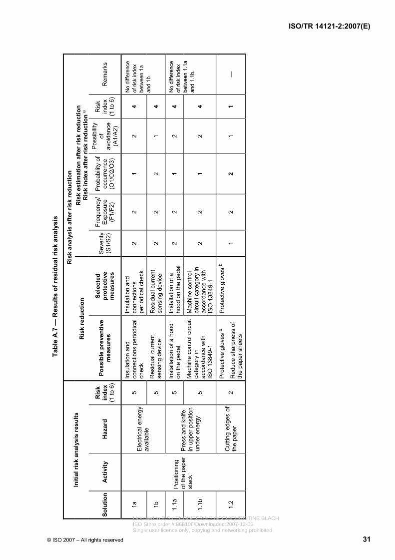
© ISO 2007 – All rights reserved 31
Tabl
e A
.7 —
Res
ults
of r
esid
ual r
isk
anal
ysis
Ris
k an
alys
is a
fter r
isk
redu
ctio
n In
itial
risk
ana
lysi
s re
sults
R
isk
redu
ctio
n R
isk
estim
atio
n af
ter r
isk
redu
ctio
n R
isk
inde
x af
ter r
isk
redu
ctio
n a
Solu
tion
Act
ivity
H
azar
d R
isk
inde
x (1
to 6
)
Poss
ible
pre
vent
ive
mea
sure
s
Sele
cted
pr
otec
tive
mea
sure
s
Sev
erity
(S
1/S
2)
Freq
uenc
y/
Exp
osur
e (F
1/F2
)
Pro
babi
lity
of
occu
rren
ce
(O1/
O2/
O3)
Pos
sibi
lity
of
avoi
danc
e (A
1/A
2)
Ris
k in
dex
(1 to
6)
Rem
arks
1a
5 In
sula
tion
and
conn
ectio
ns
perio
dica
l che
ck
2 2
1 2
4
1b
Ele
ctric
al e
nerg
y av
aila
ble
5
Insu
latio
n an
d co
nnec
tions
per
iodi
cal
chec
k
Res
idua
l cur
rent
se
nsin
g de
vice
R
esid
ual c
urre
nt
sens
ing
devi
ce
2 2
2 1
4
No
diffe
renc
e of
risk
inde
x be
twee
n 1a
an
d 1b
.
1.1a
5
Inst
alla
tion
of a
ho
od o
n th
e pe
dal
2 2
1 2
4
1.1b
Pre
ss a
nd k
nife
in
upp
er p
ositi
on
unde
r ene
rgy
5
Inst
alla
tion
of a
hoo
d on
the
peda
l
Mac
hine
con
trol c
ircui
t ca
tego
ry in
ac
cord
ance
with
IS
O 1
3849
-1
Mac
hine
con
trol
circ
uit c
ateg
ory
in
acco
rdan
ce w
ith
ISO
138
49-1
2 2
1 2
4
No
diffe
renc
e of
risk
inde
x be
twee
n 1.
1a
and
1.1b
.
1.2
Pos
ition
ing
of th
e pa
per
stac
k
Cut
ting
edge
s of
th
e pa
per
2 P
rote
ctiv
e gl
oves
b
Red
uce
shar
pnes
s of
th
e pa
per s
heet
s
Pro
tect
ive
glov
es b
1
2 2
1 1
—
ISO/TR 14121-2:2007(E)
Licensed to RISK ENGINEERING GCCH/CHRISTINE BLACHISO Store order #:868106/Downloaded:2007-12-05Single user licence only, copying and networking prohibited

32 © ISO 2007 – All rights reserved
Tabl
e A
.7 (c
ontin
ued)
Ris
k an
alys
is a
fter r
isk
redu
ctio
n In
itial
risk
ana
lysi
s re
sults
R
isk
redu
ctio
n R
isk
estim
atio
n af
ter r
isk
redu
ctio
n R
isk
inde
x af
ter r
isk
redu
ctio
n a
Solu
tion
Act
ivity
H
azar
d R
isk
inde
x (1
to 6
)
Poss
ible
pre
vent
ive
mea
sure
s Se
lect
ed
prot
ectiv
e m
easu
res
Sev
erity
(S
1/S
2)
Freq
uenc
y/
Exp
osur
e (F
1/F2
)
Pro
babi
lity
of
occu
rren
ce
(O1/
O2/
O3)
Pos
sibi
lity
of
avoi
danc
e (A
1/A
2)
Ris
k in
dex
(1 to
6)
Rem
arks
2a
4
Trig
gerin
g of
the
pres
s m
ovem
ent b
y a
two-
hand
con
trol
devi
ce a
nd m
achi
ne
cont
rol c
ircui
t ca
tego
ry in
ac
cord
ance
with
IS
O 1
3849
-1
2 1
1 2
2
The
mos
t ef
ficie
nt ri
sk
redu
ctio
n m
eans
is 2
d,
follo
wed
by
2a
or 2
c.
2b
4 Tr
aini
ng
2 1
2 2
3
2c
3
Ped
al c
ontro
l ac
tuat
or w
ith c
ontro
l ci
rcui
t cat
egor
y in
ac
cord
ance
with
IS
O 1
3849
-1
2 1
1 2
2
Sol
utio
n 2b
al
one
is n
ot
adeq
uate
to
redu
ce th
e ris
k.
2d
Pre
ssur
e on
th
e pa
per
stac
k
Ver
tical
m
ovem
ent o
f the
pr
ess
(app
lied
forc
e of
1 0
00 N
)
3
Trig
gerin
g of
the
pres
s m
ovem
ent b
y a
two-
hand
con
trol d
evic
e an
d m
achi
ne c
ontro
l ci
rcui
t cat
egor
y in
ac
cord
ance
with
IS
O 1
3849
-1
Trai
ning
Trig
gerin
g of
the
pres
s m
ovem
ent b
y a
peda
l co
ntro
l act
uato
r with
co
ntro
l circ
uit c
ateg
ory
in a
ccor
danc
e w
ith
ISO
138
49-1
Red
uce
pres
sure
be
fore
the
pres
s re
ache
s th
e pa
per
stac
k
Ped
al c
ontro
l ac
tuat
or w
ith c
ontro
l ci
rcui
t cat
egor
y in
ac
cord
ance
with
IS
O 1
3849
-1
Red
uce
pres
sure
be
fore
the
pres
s re
ache
s th
e pa
per
stac
k
1 1
1 2
1
3a
Pap
er
cutti
ng
4
Trig
gerin
g of
the
knife
mov
emen
t by
a tw
o-ha
nd c
ontro
l de
vice
with
con
trol
circ
uit c
ateg
ory
in
acco
rdan
ce w
ith
ISO
138
49-1
2 1
1 2
2
3b
Ver
tical
m
ovem
ent o
f th
e kn
ife
3
Trig
gerin
g of
the
knife
m
ovem
ent b
y a
two-
hand
con
trol d
evic
e w
ith c
ontro
l circ
uit
cate
gory
in
acco
rdan
ce w
ith
ISO
138
49-1
D
etec
tion
of p
rese
nce
of w
orke
r's h
ands
with
sa
fety
ligh
t cur
tain
Det
ectio
n of
pr
esen
ce o
f w
orke
r's h
ands
with
sa
fety
ligh
t cur
tain
2 1
1 2
2
No
diffe
renc
e of
resu
lt be
twee
n 3a
an
d 3b
a Th
e fig
ures
in b
old
are
thos
e th
at h
ave
chan
ged
as a
res u
lt of
the
prop
osed
pro
tect
ive
mea
sure
s.
b Fo
r qua
lity
prin
ting
of s
peci
al p
aper
s, th
e w
earin
g of
glo
ves
is m
anda
tory
.
ISO/TR 14121-2:2007(E)
Licensed to RISK ENGINEERING GCCH/CHRISTINE BLACHISO Store order #:868106/Downloaded:2007-12-05Single user licence only, copying and networking prohibited
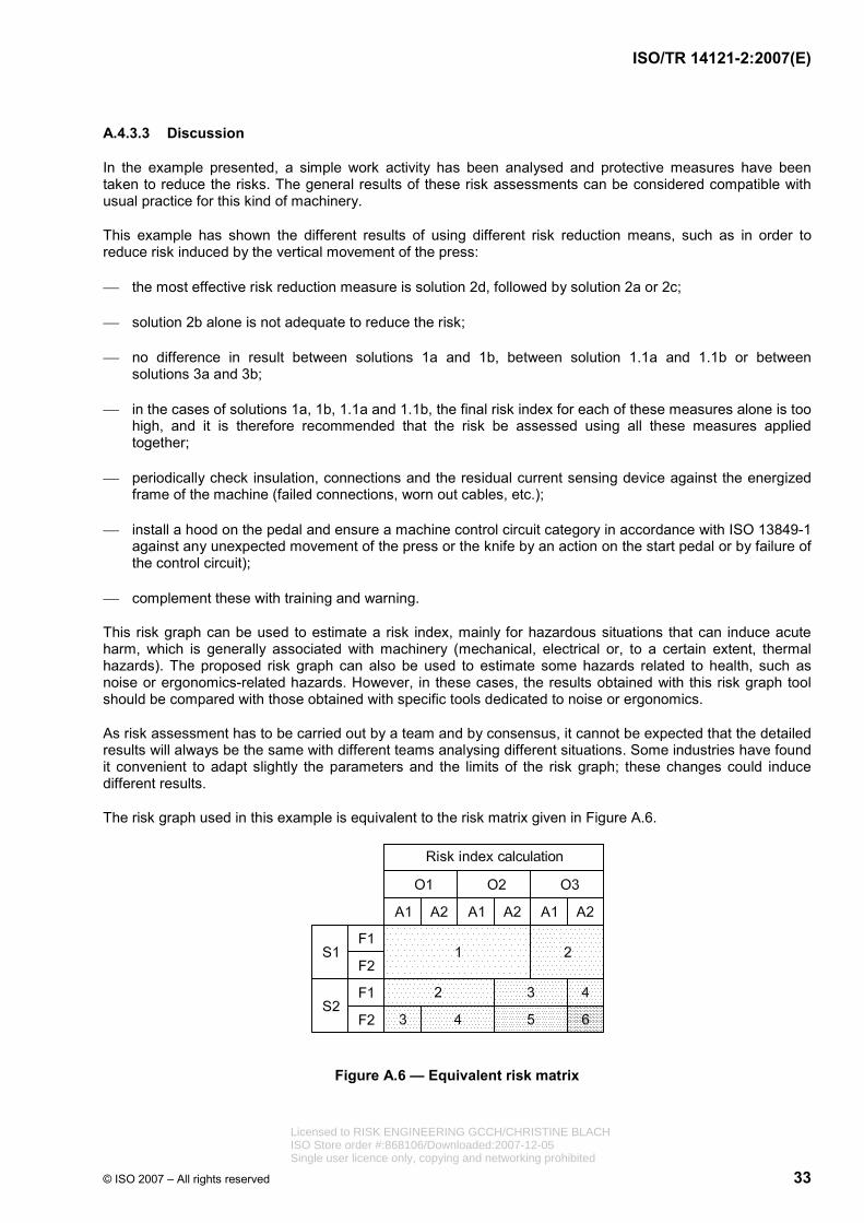
ISO/TR 14121-2:2007(E)
© ISO 2007 – All rights reserved 33
A.4.3.3 Discussion
In the example presented, a simple work activity has been analysed and protective measures have been taken to reduce the risks. The general results of these risk assessments can be considered compatible with usual practice for this kind of machinery.
This example has shown the different results of using different risk reduction means, such as in order to reduce risk induced by the vertical movement of the press:
⎯ the most effective risk reduction measure is solution 2d, followed by solution 2a or 2c;
⎯ solution 2b alone is not adequate to reduce the risk;
⎯ no difference in result between solutions 1a and 1b, between solution 1.1a and 1.1b or between solutions 3a and 3b;
⎯ in the cases of solutions 1a, 1b, 1.1a and 1.1b, the final risk index for each of these measures alone is too high, and it is therefore recommended that the risk be assessed using all these measures applied together;
⎯ periodically check insulation, connections and the residual current sensing device against the energized frame of the machine (failed connections, worn out cables, etc.);
⎯ install a hood on the pedal and ensure a machine control circuit category in accordance with ISO 13849-1 against any unexpected movement of the press or the knife by an action on the start pedal or by failure of the control circuit);
⎯ complement these with training and warning.
This risk graph can be used to estimate a risk index, mainly for hazardous situations that can induce acute harm, which is generally associated with machinery (mechanical, electrical or, to a certain extent, thermal hazards). The proposed risk graph can also be used to estimate some hazards related to health, such as noise or ergonomics-related hazards. However, in these cases, the results obtained with this risk graph tool should be compared with those obtained with specific tools dedicated to noise or ergonomics.
As risk assessment has to be carried out by a team and by consensus, it cannot be expected that the detailed results will always be the same with different teams analysing different situations. Some industries have found it convenient to adapt slightly the parameters and the limits of the risk graph; these changes could induce different results.
The risk graph used in this example is equivalent to the risk matrix given in Figure A.6.
Figure A.6 — Equivalent risk matrix
Licensed to RISK ENGINEERING GCCH/CHRISTINE BLACHISO Store order #:868106/Downloaded:2007-12-05Single user licence only, copying and networking prohibited
ISO/TR 14121-2:2007(E)
34 © ISO 2007 – All rights reserved
A.5 Risk assessment using numerical scoring
A.5.1 General
Some people find it easier to think about risk and how it is derived in terms of numbers. This is not at all unusual in our digital age. Being able to see risk represented by a number somehow adds specificity to the process of risk reduction. Having an acceptable risk level at a specific number within the numerical risk range, from lowest to highest risk, can provide focus in risk reduction decision-making. The ability to select one number from within the class integer ranges can allow for more refined choices than are permitted by qualitative terms.
A.5.2 Description of the tool or method
In this example, there are two parameters, severity and probability, each divided into the four classes shown.
The severity parameter has the following severity scores (SS):
⎯ catastrophic (SS W 100);
⎯ serious (99 W SS W 90);
⎯ moderate (89 W SS W 30);
⎯ minor (29 W SS W 0).
The probability parameter has the following probability scores (PS):
⎯ very likely (PS W 100) likely or certain to occur;
⎯ likely (99 W PS W 70) can occur (but not probable);
⎯ unlikely (69 W PS W 30) not likely to occur;
⎯ remote (29 W PS W 0) occurrence so remote as to be essentially zero.
In this example, the formula for combining probability and severity is given by Equation (A.1):
PS + SS = RS (A.1)
where RS is the risk score.
The RS can then be interpreted according to Table A.8.
Table A.8 — Risk score categories used
— high W 160
159 W medium W 120
119 W low W 90
89 W negligible W 0
So, for example, a task hazard associated with very severe injury may have SS = 95, and its probability may be in the likely range PS = 80. The risk value for this task hazard is then 95 + 80 = 175. This high risk would be unacceptable if the acceptable risk level has been set at 130.
Licensed to RISK ENGINEERING GCCH/CHRISTINE BLACHISO Store order #:868106/Downloaded:2007-12-05Single user licence only, copying and networking prohibited
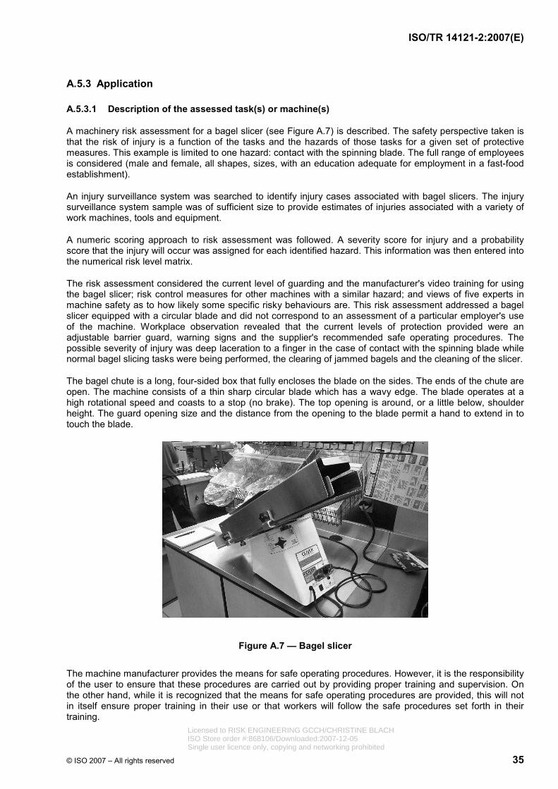
ISO/TR 14121-2:2007(E)
© ISO 2007 – All rights reserved 35
A.5.3 Application
A.5.3.1 Description of the assessed task(s) or machine(s)
A machinery risk assessment for a bagel slicer (see Figure A.7) is described. The safety perspective taken is that the risk of injury is a function of the tasks and the hazards of those tasks for a given set of protective measures. This example is limited to one hazard: contact with the spinning blade. The full range of employees is considered (male and female, all shapes, sizes, with an education adequate for employment in a fast-food establishment).
An injury surveillance system was searched to identify injury cases associated with bagel slicers. The injury surveillance system sample was of sufficient size to provide estimates of injuries associated with a variety of work machines, tools and equipment.
A numeric scoring approach to risk assessment was followed. A severity score for injury and a probability score that the injury will occur was assigned for each identified hazard. This information was then entered into the numerical risk level matrix.
The risk assessment considered the current level of guarding and the manufacturer's video training for using the bagel slicer; risk control measures for other machines with a similar hazard; and views of five experts in machine safety as to how likely some specific risky behaviours are. This risk assessment addressed a bagel slicer equipped with a circular blade and did not correspond to an assessment of a particular employer's use of the machine. Workplace observation revealed that the current levels of protection provided were an adjustable barrier guard, warning signs and the supplier's recommended safe operating procedures. The possible severity of injury was deep laceration to a finger in the case of contact with the spinning blade while normal bagel slicing tasks were being performed, the clearing of jammed bagels and the cleaning of the slicer.
The bagel chute is a long, four-sided box that fully encloses the blade on the sides. The ends of the chute are open. The machine consists of a thin sharp circular blade which has a wavy edge. The blade operates at a high rotational speed and coasts to a stop (no brake). The top opening is around, or a little below, shoulder height. The guard opening size and the distance from the opening to the blade permit a hand to extend in to touch the blade.
Figure A.7 — Bagel slicer
The machine manufacturer provides the means for safe operating procedures. However, it is the responsibility of the user to ensure that these procedures are carried out by providing proper training and supervision. On the other hand, while it is recognized that the means for safe operating procedures are provided, this will not in itself ensure proper training in their use or that workers will follow the safe procedures set forth in their training.
Licensed to RISK ENGINEERING GCCH/CHRISTINE BLACHISO Store order #:868106/Downloaded:2007-12-05Single user licence only, copying and networking prohibited
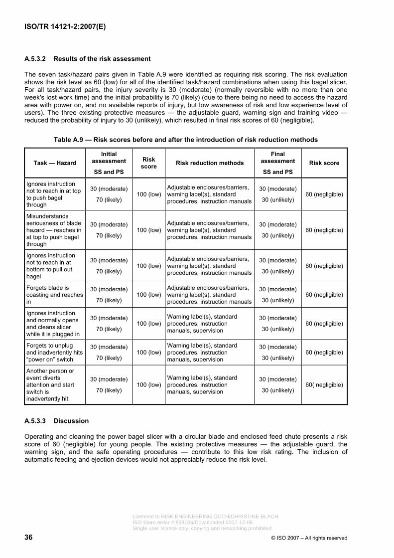
ISO/TR 14121-2:2007(E)
36 © ISO 2007 – All rights reserved
A.5.3.2 Results of the risk assessment
The seven task/hazard pairs given in Table A.9 were identified as requiring risk scoring. The risk evaluation shows the risk level as 60 (low) for all of the identified task/hazard combinations when using this bagel slicer. For all task/hazard pairs, the injury severity is 30 (moderate) (normally reversible with no more than one week's lost work time) and the initial probability is 70 (likely) (due to there being no need to access the hazard area with power on, and no available reports of injury, but low awareness of risk and low experience level of users). The three existing protective measures — the adjustable guard, warning sign and training video — reduced the probability of injury to 30 (unlikely), which resulted in final risk scores of 60 (negligible).
Table A.9 — Risk scores before and after the introduction of risk reduction methods
Task — Hazard Initial
assessment
SS and PS
Risk score Risk reduction methods
Final assessment
SS and PS Risk score
Ignores instruction not to reach in at top to push bagel through
30 (moderate)
70 (likely) 100 (low)
Adjustable enclosures/barriers, warning label(s), standard procedures, instruction manuals
30 (moderate)
30 (unlikely) 60 (negligible)
Misunderstands seriousness of blade hazard — reaches in at top to push bagel through
30 (moderate)
70 (likely) 100 (low)
Adjustable enclosures/barriers, warning label(s), standard procedures, instruction manuals
30 (moderate)
30 (unlikely) 60 (negligible)
Ignores instruction not to reach in at bottom to pull out bagel
30 (moderate)
70 (likely) 100 (low)
Adjustable enclosures/barriers, warning label(s), standard procedures, instruction manuals
30 (moderate)
30 (unlikely) 60 (negligible)
Forgets blade is coasting and reaches in
30 (moderate)
70 (likely) 100 (low)
Adjustable enclosures/barriers, warning label(s), standard procedures, instruction manuals
30 (moderate)
30 (unlikely) 60 (negligible)
Ignores instruction and normally opens and cleans slicer while it is plugged in
30 (moderate)
70 (likely) 100 (low)
Warning label(s), standard procedures, instruction manuals, supervision
30 (moderate)
30 (unlikely) 60 (negligible)
Forgets to unplug and inadvertently hits “power on” switch
30 (moderate)
70 (likely) 100 (low)
Warning label(s), standard procedures, instruction manuals, supervision
30 (moderate)
30 (unlikely) 60 (negligible)
Another person or event diverts attention and start switch is inadvertently hit
30 (moderate)
70 (likely) 100 (low)
Warning label(s), standard procedures, instruction manuals, supervision
30 (moderate)
30 (unlikely) 60( negligible)
A.5.3.3 Discussion
Operating and cleaning the power bagel slicer with a circular blade and enclosed feed chute presents a risk score of 60 (negligible) for young people. The existing protective measures — the adjustable guard, the warning sign, and the safe operating procedures — contribute to this low risk rating. The inclusion of automatic feeding and ejection devices would not appreciably reduce the risk level.
Licensed to RISK ENGINEERING GCCH/CHRISTINE BLACHISO Store order #:868106/Downloaded:2007-12-05Single user licence only, copying and networking prohibited
ISO/TR 14121-2:2007(E)
© ISO 2007 – All rights reserved 37
A.6 Quantified risk estimation
NOTE See 5.4.4.5.
IMPORTANT — The text in italics throughout this clause (A.6) relates to the illustrative example.
A.6.1 General
This is a brief overview of a method for risk estimation used to examine in more detail a single risk considered to be too complex to be easily estimated qualitatively.
Before using such a method, a thorough hazard identification will first need to be carried out in accordance with ISO 14121-1.
The forms used are based upon an underlying fault tree of accident causation. Forms 3 A and 3 B can be modified or appended according to specific needs as long as the underlying logic is checked using fault trees. The risk estimated using this method is expressed as an annual frequency of different levels of harm allowing comparisons to be made with accident statistics in the industry or numerical risk criteria. Lookup tables of suggested probabilities and guidance are provided so that the user does not have to estimate all these values from first principles. Again, these lookup tables can be modified or added to according to the user's needs or sources of data.
The use of the method is described with reference to a powered roof support used on a coalmine face. The accident scenario that will be used as an example is one cause and consequence of the hazardous situation “damaged high voltage cables”.
A.6.2 Description of the tool or method
A.6.2.1 Form 1 — Description of accident scenario
The form given as Table A.10 is used to describe each accident scenario based on the information recorded in the hazard identification. There can be several different hazardous situations for each hazard and/or several different hazardous events for each hazardous situation. In the example used, the damaged high voltage cables pose an electrocution hazard or ignition hazard.
One form should be used for each combination of hazard, hazardous situation and hazardous event. Some hazardous situations are only relevant to certain types of people, e.g. maintenance technicians, others will be relevant to a range of different types of people (operators, maintenance technicians or passers-by). This should be made clear on the form.
The objective is to clearly describe, as closely as possible, everything (chain of events) that has to happen or exist for the hazardous event to occur. When doing this it is helpful to consider the aspects described in ISO 14121-1:2007, 7.3.
Licensed to RISK ENGINEERING GCCH/CHRISTINE BLACHISO Store order #:868106/Downloaded:2007-12-05Single user licence only, copying and networking prohibited
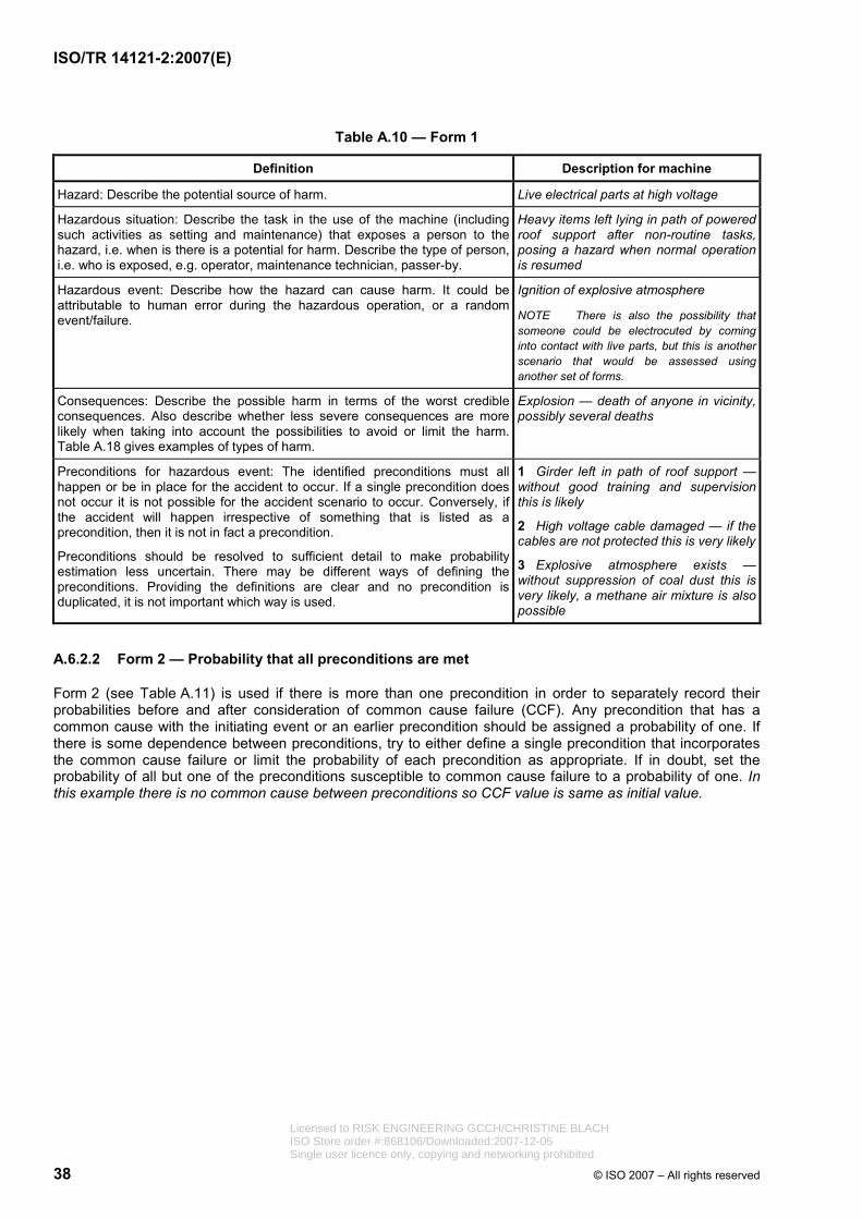
ISO/TR 14121-2:2007(E)
38 © ISO 2007 – All rights reserved
Table A.10 — Form 1
Definition Description for machine
Hazard: Describe the potential source of harm. Live electrical parts at high voltage
Hazardous situation: Describe the task in the use of the machine (including such activities as setting and maintenance) that exposes a person to the hazard, i.e. when is there is a potential for harm. Describe the type of person, i.e. who is exposed, e.g. operator, maintenance technician, passer-by.
Heavy items left lying in path of powered roof support after non-routine tasks,posing a hazard when normal operation is resumed
Ignition of explosive atmosphere Hazardous event: Describe how the hazard can cause harm. It could be attributable to human error during the hazardous operation, or a random event/failure. NOTE There is also the possibility that
someone could be electrocuted by coming into contact with live parts, but this is another scenario that would be assessed using another set of forms.
Consequences: Describe the possible harm in terms of the worst credible consequences. Also describe whether less severe consequences are more likely when taking into account the possibilities to avoid or limit the harm. Table A.18 gives examples of types of harm.
Explosion — death of anyone in vicinity, possibly several deaths
Preconditions for hazardous event: The identified preconditions must all happen or be in place for the accident to occur. If a single precondition does not occur it is not possible for the accident scenario to occur. Conversely, if the accident will happen irrespective of something that is listed as a precondition, then it is not in fact a precondition.
Preconditions should be resolved to sufficient detail to make probability estimation less uncertain. There may be different ways of defining the preconditions. Providing the definitions are clear and no precondition is duplicated, it is not important which way is used.
1 Girder left in path of roof support —without good training and supervision this is likely
2 High voltage cable damaged — if the cables are not protected this is very likely
3 Explosive atmosphere exists —without suppression of coal dust this is very likely, a methane air mixture is also possible
A.6.2.2 Form 2 — Probability that all preconditions are met
Form 2 (see Table A.11) is used if there is more than one precondition in order to separately record their probabilities before and after consideration of common cause failure (CCF). Any precondition that has a common cause with the initiating event or an earlier precondition should be assigned a probability of one. If there is some dependence between preconditions, try to either define a single precondition that incorporates the common cause failure or limit the probability of each precondition as appropriate. If in doubt, set the probability of all but one of the preconditions susceptible to common cause failure to a probability of one. In this example there is no common cause between preconditions so CCF value is same as initial value.
Licensed to RISK ENGINEERING GCCH/CHRISTINE BLACHISO Store order #:868106/Downloaded:2007-12-05Single user licence only, copying and networking prohibited
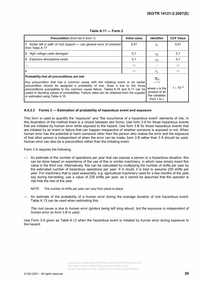
ISO/TR 14121-2:2007(E)
© ISO 2007 – All rights reserved 39
Table A.11 — Form 2
Precondition (from list in form 1) Initial value Identifier CCF Value
1 Girder left in path of roof support — use general error of omission from Table A.17
0,01 p1 0,01
2 High voltage cable damaged 0,1 p2 0,1
3 Explosive atmosphere exists 0,1 p3 0,1
… — … —
n — pn —
Probability that all preconditions are met
Any precondition that has a common cause with the initiating event or an earlier precondition should be assigned a probability of one. Draw a line to link those preconditions susceptible to the common cause failure. Tables A.16 and A.17 can be useful in deciding values of probabilities. Failure rates can be obtained from the supplier or estimated using Table A.15.
1, ii n
p=π
where π is the product of all the variables from 1 to n
1 × 10⁻⁴
A.6.2.3 Forms 3 — Estimation of probability of hazardous event and exposure
This form is used to quantify the “exposure” and “the occurrence of a hazardous event” elements of risk. In this illustration of the method there is a choice between two forms: Use form 3 A for those hazardous events that are initiated by human error while exposed to the hazard. Use form 3 B for those hazardous events that are initiated by an event or failure that can happen irrespective of whether someone is exposed or not. When human error has the potential to harm someone other than the person who makes the error and the exposure of that other person is independent of when the error can be made, form 3 B rather than 3 A should be used. Human error can also be a precondition rather than the initiating event.
Form 3 A requires the following.
⎯ An estimate of the number of operations per year that can expose a person to a hazardous situation: this can be done based on experience of the use of this or similar machinery, in which case simply insert this value in the third row. Alternatively, this can be calculated by multiplying the number of shifts per year by the estimated number of hazardous operations per year. If in doubt, it is best to assume 235 shifts per year. For machinery that is used seasonally, e.g. agricultural machinery used for a few months of the year, say during harvesting, use a value of 235 shifts per year, as it cannot be assumed that the operator is risk-free the rest of the year.
NOTE The number of shifts per year can vary from place to place.
⎯ An estimate of the probability of a human error during the average duration of one hazardous event: Table A.13 can be used when estimating this.
The root cause is due to human error (girders being left lying about), but the exposure is independent of human error so form 3 B is used.
Use Form 3 A given as Table A.12 when the hazardous event is initiated by human error during exposure to the hazard.
Licensed to RISK ENGINEERING GCCH/CHRISTINE BLACHISO Store order #:868106/Downloaded:2007-12-05Single user licence only, copying and networking prohibited
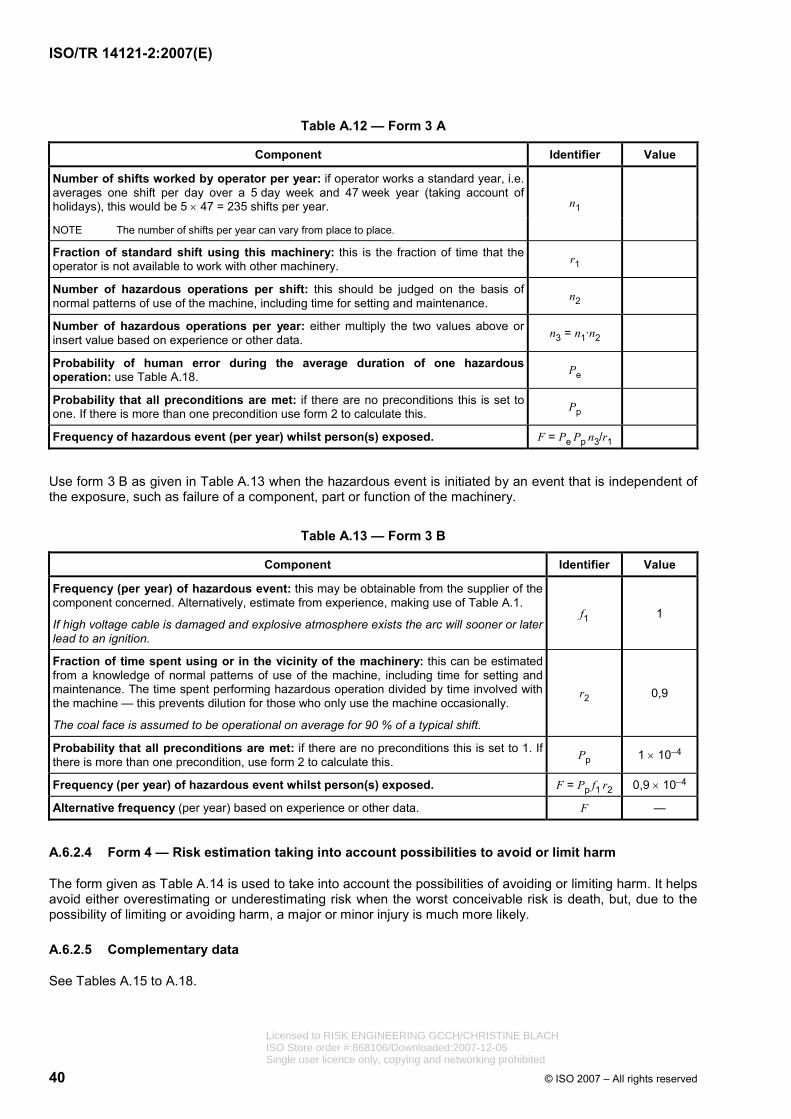
ISO/TR 14121-2:2007(E)
40 © ISO 2007 – All rights reserved
Table A.12 — Form 3 A
Component Identifier Value
Number of shifts worked by operator per year: if operator works a standard year, i.e. averages one shift per day over a 5 day week and 47 week year (taking account of holidays), this would be 5 × 47 = 235 shifts per year.
NOTE The number of shifts per year can vary from place to place.
n1
Fraction of standard shift using this machinery: this is the fraction of time that the operator is not available to work with other machinery. r1
Number of hazardous operations per shift: this should be judged on the basis of normal patterns of use of the machine, including time for setting and maintenance. n2
Number of hazardous operations per year: either multiply the two values above or insert value based on experience or other data. n3 = n1·n2
Probability of human error during the average duration of one hazardous operation: use Table A.18. Pe
Probability that all preconditions are met: if there are no preconditions this is set to one. If there is more than one precondition use form 2 to calculate this. Pp
Frequency of hazardous event (per year) whilst person(s) exposed. F = Pe Pp n3/r1
Use form 3 B as given in Table A.13 when the hazardous event is initiated by an event that is independent of the exposure, such as failure of a component, part or function of the machinery.
Table A.13 — Form 3 B
Component Identifier Value
Frequency (per year) of hazardous event: this may be obtainable from the supplier of the component concerned. Alternatively, estimate from experience, making use of Table A.1.
If high voltage cable is damaged and explosive atmosphere exists the arc will sooner or later lead to an ignition.
f1 1
Fraction of time spent using or in the vicinity of the machinery: this can be estimated from a knowledge of normal patterns of use of the machine, including time for setting and maintenance. The time spent performing hazardous operation divided by time involved with the machine — this prevents dilution for those who only use the machine occasionally.
The coal face is assumed to be operational on average for 90 % of a typical shift.
r2 0,9
Probability that all preconditions are met: if there are no preconditions this is set to 1. If there is more than one precondition, use form 2 to calculate this. Pp 1 × 10⁻⁴
Frequency (per year) of hazardous event whilst person(s) exposed. F = Pp f1 r2 0,9 × 10⁻⁴
Alternative frequency (per year) based on experience or other data. F —
A.6.2.4 Form 4 — Risk estimation taking into account possibilities to avoid or limit harm
The form given as Table A.14 is used to take into account the possibilities of avoiding or limiting harm. It helps avoid either overestimating or underestimating risk when the worst conceivable risk is death, but, due to the possibility of limiting or avoiding harm, a major or minor injury is much more likely.
A.6.2.5 Complementary data
See Tables A.15 to A.18.
Licensed to RISK ENGINEERING GCCH/CHRISTINE BLACHISO Store order #:868106/Downloaded:2007-12-05Single user licence only, copying and networking prohibited
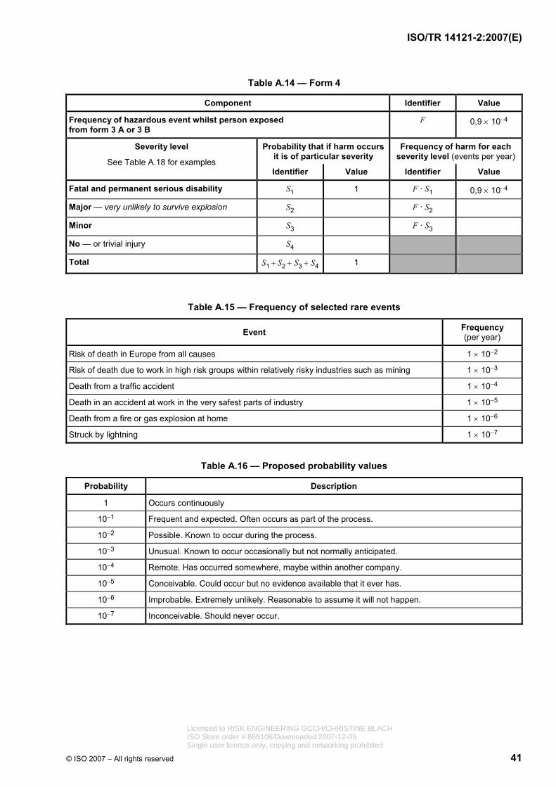
ISO/TR 14121-2:2007(E)
© ISO 2007 – All rights reserved 41
Table A.14 — Form 4
Component Identifier Value
Frequency of hazardous event whilst person exposed from form 3 A or 3 B
F 0,9 × 10⁻⁴
Probability that if harm occurs it is of particular severity
Frequency of harm for each severity level (events per year)
Severity level
See Table A.18 for examples Identifier Value Identifier Value
Fatal and permanent serious disability S1 1 F · S1 0,9 × 10⁻⁴
Major — very unlikely to survive explosion S2 F · S2
Minor S3 F · S3
No — or trivial injury S4
Total S1 + S2 + S3 + S4 1
Table A.15 — Frequency of selected rare events
Event Frequency (per year)
Risk of death in Europe from all causes 1 × 10⁻²
Risk of death due to work in high risk groups within relatively risky industries such as mining 1 × 10⁻³
Death from a traffic accident 1 × 10⁻⁴
Death in an accident at work in the very safest parts of industry 1 × 10⁻⁵
Death from a fire or gas explosion at home 1 × 10⁻⁶
Struck by lightning 1 × 10⁻⁷
Table A.16 — Proposed probability values
Probability Description
1 Occurs continuously
10−1 Frequent and expected. Often occurs as part of the process.
10−2 Possible. Known to occur during the process.
10−3 Unusual. Known to occur occasionally but not normally anticipated.
10−4 Remote. Has occurred somewhere, maybe within another company.
10−5 Conceivable. Could occur but no evidence available that it ever has.
10−6 Improbable. Extremely unlikely. Reasonable to assume it will not happen.
10−7 Inconceivable. Should never occur.
Licensed to RISK ENGINEERING GCCH/CHRISTINE BLACHISO Store order #:868106/Downloaded:2007-12-05Single user licence only, copying and networking prohibited

ISO/TR 14121-2:2007(E)
42 © ISO 2007 – All rights reserved
Table A.17 — Probability of human error
Error probability Task
1 × 10⁻⁴ Routine, good feedback with time to make use of it, good appreciation of hazard
0,001 Routine, simple
0,01 General error of omission
0,1 Non-routine, complicated
0,1 High stress, time constraint 30 min
0,9 High stress, time constraint 5 min
1 High stress, time constraint 1 min
1 Error in second step, having already erred in first
Table A.18 — Examples of types of harm for each severity level
Severity level Example injuries
Fatality and permanent serious disability Quadriplegia
Paraplegia
Prolonged unconsciousness (coma)
Permanent brain damage
Major injury Any fracture (other than to fingers, thumbs or toes)
Burns causing permanent scarring
Damage to sight, partial or total
Any amputation
Loss of consciousness (not prolonged)
Dislocation of shoulder, hip, knee or spine
Treatment required due to exposure to fumes
Anything requiring resuscitation
Minor injury Minor broken bones (fingers, toes)
Cuts and bruises
Minor burns, temporary scarring
Any other injury requiring first aid only
No injury and near misses No injury, including the possibility of avoidance
A.6.2.6 Discussion
The value of estimating the risk by breaking down the accident scenario in this way is not so much the number obtained but the understanding of all the factors that influence the risk. This can assist in identifying a range of risk reduction measures. For instance, in this example, training and competence appear to be important for risk reduction.
Licensed to RISK ENGINEERING GCCH/CHRISTINE BLACHISO Store order #:868106/Downloaded:2007-12-05Single user licence only, copying and networking prohibited
ISO/TR 14121-2:2007(E)
© ISO 2007 – All rights reserved 43
The full risk assessment process, led by an experienced practitioner together with designers and installation/maintenance engineers, looking at a specific powered roof support system as a team required the following schedule:
⎯ a day for familiarization/determination of limits;
⎯ two days for hazard identification that produced a list of 41 relevant hazards and hazardous situations;
⎯ a day for risk estimation where ten hazardous situations were looked at using a guided quantitative method similar to the one described above, the rest being estimated qualitatively;
⎯ five days to write up the results, carry out a limited risk evaluation and do a comprehensive comparison with accident statistics, although this would have been significantly reduced had the method been computerized;
⎯ a day to feed back the results to the team and members of the board.
The risks estimated using this tool took account of existing protective measures in the design as well as common industry working practices. The estimated risks were used to inform decisions about whether additional risk reduction measures were necessary. The design team decided that altering the design, for example, to include a protective barrier, was not practicable for this amount of risk. However, the risk and the measures required to be taken by the user to control it would be described in the information for use for the machinery.
The method is ideally used by a team led by a suitably experienced practitioner. The method helps generate detailed technical discussions and challenges the existing design and assumptions made about the hazards and risks. The extra effort required to use such a method is therefore unlikely to be cost-effective for well-established machinery for which there is standardized or widely recognized good practice in terms of appropriate protective measures.
A.7 Risk assessment using hybrid method
A.7.1 General
This risk assessment method quantifies the qualitative parameters. It is a hybrid method of numerical scoring and a matrix.
It ranges from hazard identification to risk estimation and risk evaluation, to protective measures to be implemented and the decision to consider the machine adequately safe.
Risk assessment using this method and tool can be done by an individual in the day-to-day work as a first step but should, as with all risk assessments, be reviewed or repeated by a team as described in 4.2.
Before starting to use this method, preparation has to be done as described in Clause 4 and the machinery limits determined as described in 5.2.
A.7.2 Description of the tool or method
Table A.19 should be used in conjunction with the following guidance information.
Pre-risk assessment
Ticking this box indicates that this is the first risk assessment. It is done in the concept phase where only specification and sketches are available. No detailed drawings are made at this stage. It is used to decide on the major systems of a machine, e.g. mechanical drive line or servo drives, hot air or ultrasonic sealing, movable guard or light barrier. See Table A.19.
Licensed to RISK ENGINEERING GCCH/CHRISTINE BLACHISO Store order #:868106/Downloaded:2007-12-05Single user licence only, copying and networking prohibited

ISO/TR 14121-2:2007(E)
44 © ISO 2007 – All rights reserved
Intermediate risk assessment
The intermediate risk assessment box is ticked for all intermediate risk assessments performed during the development of a machine. Two sets of hazards are dealt with in this phase. Where in the pre-risk assessment phase protective measures were indicated, these are implemented and assessed again in this phase. The design of the machine changes during the development. Risk assessments have to follow together with the design review along the project. New hazards are dealt with in this phase. See Table A.19.
Follow-up risk assessment
This box is ticked at the follow-up risk assessment. Follow-up is done on implemented protective measures. No new hazard should appear in this phase. Nevertheless, where a new hazard is identified when following up on protective measures, this new hazard is also estimated and evaluated in this phase. If it requires a protective measure, a follow-up has to be done again on this protective measure. See Table A.19.
Reference number (ref. no.)
The ref. no., or serial number, is used to give each identified hazard a number for reference purposes.
Type number (type no.)
Type no., hazard type or group number is used to classify the hazards. The numbers refer to those given for the type or group according to ISO 14121-1:2007, Table A.1.
Hazard
Describe the hazard. The type no. identifies the type or group of hazard. Indicate the origin of the hazard type or group. For example, if the hazard is a crushing hazard, indicate this by “1” in the type no. column and by “crushing” in the hazard column.
The same hazard could require several estimations due to different hazardous situations and hazardous events.
Severity, Se
Se is the severity of possible harm as an outcome from the identified hazard. The severity is scored as follows:
1 scratches, bruises that are cured by first aid or similar;
2 more severe scratches, bruises, stabbing, which require medical attention from professionals;
3 normally irreversible injury; it will be slightly difficult to continue work after healing;
4 irreversible injury in such a way that it will be very difficult to continue work after healing, if possible at all.
Frequency, Fr
Fr is the average interval between frequency of exposure and its duration. The frequency is scored as follows:
2 interval between exposure is more than a year;
3 interval between exposure is more than two weeks but less than or equal to a year;
4 interval between exposure is more than a day but less than or equal to two weeks;
5 interval between exposure is more than an hour but less than or equal to a day.
Where the duration is shorter than 10 min, the above values may be decreased to the next level.
6 interval less than or equal to an hour. This value is not to be decreased at any time. Licensed to RISK ENGINEERING GCCH/CHRISTINE BLACHISO Store order #:868106/Downloaded:2007-12-05Single user licence only, copying and networking prohibited
ISO/TR 14121-2:2007(E)
© ISO 2007 – All rights reserved 45
Probability, Pr
Pr is the probability of occurrence of a hazardous event. Consider, for example, human behaviour, reliability of components, accident history and the nature of the component or system (e.g. a knife is always sharp, a pipe in a dairy environment is hot, electricity is dangerous by its nature) to determine the level of probability. The probability is scored as follows:
1 Negligible: for example, this kind of component never fails so that a hazardous event occurs. No possibility of human error.
2 Rarely: for example, it is unlikely that this kind of component will fail so that a hazardous event occurs. Human error is unlikely.
3 Possible: for example, this kind of component can fail so a hazardous event occurs. Human error is possible.
4 Likely: for example, this kind of component will probably fail so a hazardous event occurs. Human error is likely.
5 Very high: for example, this kind of component is not made for this application. It will fail so that a hazardous event occurs. Human behaviour is such that the likelihood of error is very high.
Avoidance, Av
Av is the possibility of avoiding or limiting harm. Consider, for example, whether the machine is to be operated by skilled or unskilled persons, how quickly a hazardous situation can lead to harm, and the awareness of risk by means of general information, direct observation or through warning signs, so as to determine the level of avoidance. The possibility of avoidance is scored as follows:
1 Likely: for example, it is likely that contact with moving parts behind an interlocked guard will be avoided in most cases should the interlocking fail and the movements continue.
3 Possible: for example, it is possible to avoid an entanglement hazard where the speed is slow.
5 Impossible: for example, it is impossible to avoid the sudden appearance of a powerful laser beam or a part of a machine becoming live because of a fault in electrical insulation.
Class, Cl
Cl is the class. Fr, Pr and Av are the constituent factors that form the probability of occurrence of harm as described in ISO 14121-1:2007, 7.2.1. Each of the three factors should be estimated independently. The worst credible assumption should be used for each factor. Fr, Pr and Av are added together in Cl. The Cl is the sum of Fr, Pr and Av, i.e. Cl = Fr + Pr + Av.
Evaluation of the risk
The risk is evaluated by using the matrix in the middle of the upper part of the form, see Table A.19.
Where the severity, Se, crosses the class, Cl, in the black area, protective measures have to be implemented to reduce risk.
Where the severity, Se, crosses the class, Cl, in the grey area, protective measures are recommended to be implemented to further reduce risk.
Where the severity, Se, crosses the class, Cl, in the remaining area, the risk is already adequately reduced.
Protective measure
Indicate the protective measure to be implemented to reduce risk. Licensed to RISK ENGINEERING GCCH/CHRISTINE BLACHISO Store order #:868106/Downloaded:2007-12-05Single user licence only, copying and networking prohibited
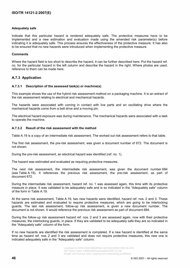
ISO/TR 14121-2:2007(E)
46 © ISO 2007 – All rights reserved
Adequately safe
Indicate that this particular hazard is rendered adequately safe. The protective measures have to be implemented and a new estimation and evaluation made using the amended risk parameter(s) before indicating it is adequately safe. This process ensures the effectiveness of the protective measure. It has also to be ensured that no new hazards were introduced when implementing the protective measure.
Comments
Where the hazard field is too short to describe the hazard, it can be further described here. Put the hazard ref. no. for the particular hazard in the left column and describe the hazard in the right. Where photos are used, reference to them can be made here.
A.7.3 Application
A.7.3.1 Description of the assessed task(s) or machine(s)
This example shows the use of the hybrid risk assessment method on a packaging machine. It is an extract of the risk assessment relating to electrical and mechanical hazards.
The hazards were associated with coming in contact with live parts and an oscillating drive where the mechanical hazards come from a belt drive and a moving pin.
The electrical hazard exposure was during maintenance. The mechanical hazards were associated with a task to operate the machine.
A.7.3.2 Result of the risk assessment with the method
Table A.19 is a copy of an intermediate risk assessment. The worked out risk assessment refers to that table.
The first risk assessment, the pre-risk assessment, was given a document number of 672. The document is not shown.
During the pre-risk assessment, an electrical hazard was identified (ref. no. 1).
The hazard was estimated and evaluated as requiring protective measures.
The next risk assessment, the intermediate risk assessment, was given the document number 684 (see Table A.19). It references the previous risk assessment, the pre-risk assessment, as part of document 672.
During the intermediate risk assessment, hazard ref. no. 1 was assessed again, this time with its protective measure in place. It was validated to be adequately safe and is so indicated in the “Adequately safe” column of the form in Table A.19.
At the same risk assessment, Table A.19, two new hazards were identified, hazard ref. nos. 2 and 3. These hazards are estimated and evaluated to require protective measures, which are going to be interlocking guards. The last risk assessment, follow-up risk assessment, is given a new document number. The document is not shown. It would reference the previous risk assessment as part of document 684.
During the follow-up risk assessment hazard ref. nos. 2 and 3 are assessed again, now with their protective measures, the interlocking guards, in place. If they are validated to be adequately safe they are so indicated in the “Adequately safe” column of the form.
If no new hazards are identified the risk assessment is completed. If a new hazard is identified at the same time as hazard ref. nos. 2 and 3 are validated and does not require protective measures, this new one is indicated adequately safe in the “Adequately safe” column.
Licensed to RISK ENGINEERING GCCH/CHRISTINE BLACHISO Store order #:868106/Downloaded:2007-12-05Single user licence only, copying and networking prohibited
ISO/TR 14121-2:2007(E)
© ISO 2007 – All rights reserved 47
If the newly identified hazard requires a protective measure this is not a follow-up risk assessment but indicated as an intermediate risk assessment. A further risk assessment, follow-up risk assessment, has to be done when protective measures have been implemented for this last hazard.
This risk assessment is a follow-up risk assessment and completes the process when no further hazard is identified requiring a protective measure.
A.7.3.3 Discussion
This method has been found to be most useful when conducted by a team (see 4.2). Teams who have used this method have included electrical and mechanical designers, field service technicians and the technical editors of the instructions for use, the team leader being someone with a deep knowledge of the method.
The method when used as part of design review has saved time and ensured that safety has been integral to the design rather than an add-on resulting in adequately safe machinery.
This risk assessment method and tool has been used in the packaging industry worldwide for several years. Several surveillance authorities also use it. It can be used in any machine-related industry.
Licensed to RISK ENGINEERING GCCH/CHRISTINE BLACHISO Store order #:868106/Downloaded:2007-12-05Single user licence only, copying and networking prohibited
48 © ISO 2007 – All rights reserved
Tabl
e A
.19
— E
xam
ple
of c
ompl
eted
hyb
rid m
etho
d fo
rm
D
ocum
ent n
o.:
68
4
Ris
k as
sess
men
t and
pro
tect
ive
mea
sure
s
Par
t of d
oc. n
o.:
672
Pro
duct
: O
scilla
ting
driv
e
P
re-r
isk
asse
ssm
ent
I
ssue
d by
: <N
ame>
XIn
term
edia
te ri
sk a
sses
smen
t
Dat
e:
2007
-09-
17
B
lack
are
a =
Saf
ety
mea
sure
s re
quire
d
Fo
llow
-up
risk
asse
ssm
ent
Gre
y ar
ea =
Saf
ety
mea
sure
s re
com
men
ded
C
onse
quen
ces
Sev
erity
C
lass
Cl (
Fr +
Pr +
Av)
P
roba
bilit
y A
void
ance
Se
3–4
5–7
8–10
11
–13
14–1
5 Fr
eque
ncy
Fr
Pr
Av
Dea
th, l
oss
of e
ye o
r arm
4
u
1 h
5
Ver
y hi
gh
5
P
erm
anen
t inj
ury,
loss
of f
inge
rs
3
> 1
h to
u 2
4 h
5Li
kely
4
Rev
ersi
ble
inju
ry, m
edic
al a
ttent
ion
2
> 24
h to
u 2
w
4P
ossi
ble
3Im
poss
ible
5
Rev
ersi
ble
inju
ry, f
irst a
id
1
> 2
w to
u 1
y
3R
arel
y 2
Pos
sibl
e 3
> 1
y 2
Neg
ligib
le
1Li
kely
1
S
e Fr
P
r A
v C
l
Pro
tect
ive
mea
sure
S
eria
l. no
. Haz
ard
no.
Haz
ard
Ade
-qu
atel
ysa
fe
1
2
Sho
ck fr
om li
ve p
arts
Yes
2 1
Fi
nger
cru
shin
g3
4
2
3
9
Int
erlo
ckin
g gu
ard
3 1
Fin
ger b
etw
een
mov
ing
pin
and
fram
e2
3
2
3
8
Int
erlo
ckin
g gu
ard
Com
men
ts o
n re
f. no
.
2
Fing
er c
rush
ing
betw
een
belt
and
belt
pulle
y
ISO/TR 14121-2:2007(E)
Licensed to RISK ENGINEERING GCCH/CHRISTINE BLACHISO Store order #:868106/Downloaded:2007-12-05Single user licence only, copying and networking prohibited
ISO/TR 14121-2:2007(E)
© ISO 2007 – All rights reserved 49
Annex B (informative)
Example application of the process of risk assessment and reduction
B.1 General
The aim of this example is to show, in a non-exhaustive way, an application of the process of the risk assessment and risk reduction during the design of a single-spindle vertical moulding machine, in accordance with the general principles set out in ISO 14121-1 and ISO 12100.
This example does not seek to embrace the complete design of this type of machine, nor to be a model to follow. It represents only an attempt to present enough information so that the reader has an overall idea of a possible way of applying the principles set out in ISO 14121-1 and ISO 12100.
B.2 and B.3 have been applied taking into account the whole life cycle of the machine. However, in B.4 the example is limited exclusively to the phase of use and, in particular to the setting and operation of the machine.
B.2 Information for the risk assessment
NOTE See ISO 14121-1:2007, 4.2.
B.2.1 Initial specifications
B.2.1.1 General
A machine is intended to be designed according to the initial specifications given in B.2.1.2 to B.2.1.4.
B.2.1.2 Basic elements
These are the following:
⎯ a stationary single spindle vertical moulding machine;
⎯ for indoor use;
⎯ used by one operator;
⎯ hand-fed;
⎯ electrically supplied.
B.2.1.3 Work to be performed with the machine
The machine is designed to modify the profile of square or rectangular cross-section wooden pieces and analogous materials (cork, chip board, fibre board and hard plastic) by moulding, rebating and grooving.
The work to be performed with this machine is as follows.
⎯ Straight work
This is the shaping of a workpiece with one face in contact with the table and a second with the fence, where the work starts at one end of the workpiece and continues through to the other end.
Licensed to RISK ENGINEERING GCCH/CHRISTINE BLACHISO Store order #:868106/Downloaded:2007-12-05Single user licence only, copying and networking prohibited

ISO/TR 14121-2:2007(E)
50 © ISO 2007 – All rights reserved
⎯ Stopped straight work
This is the machining of only a part of the workpiece length.
⎯ Curved work
This is the machining of a curve on a workpiece by having one side in contact with the table (or, if held in a jig, with the jig in contact with the table) and the other in contact with the vertical reference of a steady or ball ring guide when using a jig.
The machine is not intended for tenoning.
Only wood products clear of foreign objects (e.g. nails) are intended to be processed.
The machine is not intended to work metallic materials.
The work is to be performed with standard cutting tools that are available on the market.
The machine will be provided with different spindle speeds in order to use a wide range of tools and to suit most materials.
The spindle height will be adjustable to enable setting of the cutting tool height.
All adjustable parts of the machine (e.g. tool change, speed change) will be manually operated.
B.2.1.4 Description of the machine concept
NOTE See Figure B.1
The milling process is performed by a cutter tool mounted on a vertical spindle. The spindle turns in only one direction and can be raised and lowered through a hand-wheel (spindle unit). The spindle can turn at four different speeds (see spindle speeds below), driven by an electric motor and a set of pulleys (driver unit).
The spindle unit and the driver unit are anchored to a cast iron table that rests on a steel cabinet. Both the table and the cabinet provide good support for the workpiece and are of a height ensuring an ergonomically upright posture.
In order to guide the workpiece during the work, the machine incorporates appropriate guides.
The spindle speed is manually selected by changing a transmission belt from one pulley to another.
Figure B.1 — Machine concept Licensed to RISK ENGINEERING GCCH/CHRISTINE BLACHISO Store order #:868106/Downloaded:2007-12-05Single user licence only, copying and networking prohibited
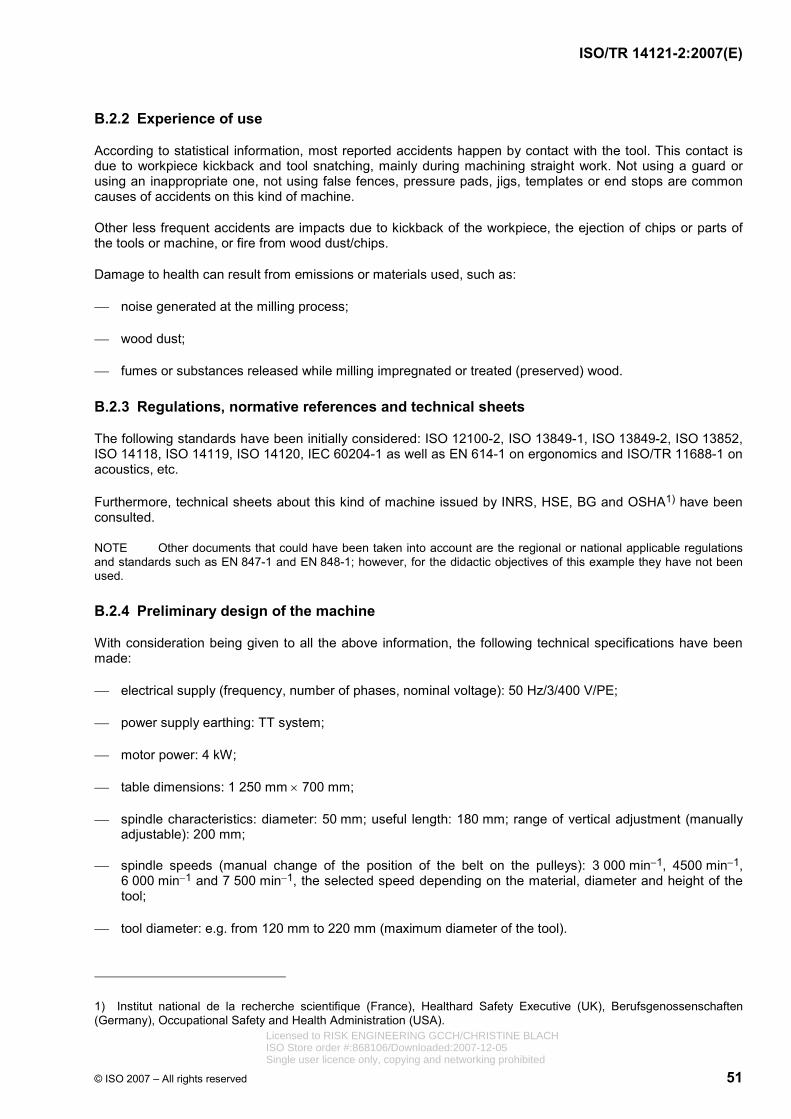
ISO/TR 14121-2:2007(E)
© ISO 2007 – All rights reserved 51
B.2.2 Experience of use
According to statistical information, most reported accidents happen by contact with the tool. This contact is due to workpiece kickback and tool snatching, mainly during machining straight work. Not using a guard or using an inappropriate one, not using false fences, pressure pads, jigs, templates or end stops are common causes of accidents on this kind of machine.
Other less frequent accidents are impacts due to kickback of the workpiece, the ejection of chips or parts of the tools or machine, or fire from wood dust/chips.
Damage to health can result from emissions or materials used, such as:
⎯ noise generated at the milling process;
⎯ wood dust;
⎯ fumes or substances released while milling impregnated or treated (preserved) wood.
B.2.3 Regulations, normative references and technical sheets
The following standards have been initially considered: ISO 12100-2, ISO 13849-1, ISO 13849-2, ISO 13852, ISO 14118, ISO 14119, ISO 14120, IEC 60204-1 as well as EN 614-1 on ergonomics and ISO/TR 11688-1 on acoustics, etc.
Furthermore, technical sheets about this kind of machine issued by INRS, HSE, BG and OSHA1) have been consulted.
NOTE Other documents that could have been taken into account are the regional or national applicable regulations and standards such as EN 847-1 and EN 848-1; however, for the didactic objectives of this example they have not been used.
B.2.4 Preliminary design of the machine
With consideration being given to all the above information, the following technical specifications have been made:
⎯ electrical supply (frequency, number of phases, nominal voltage): 50 Hz/3/400 V/PE;
⎯ power supply earthing: TT system;
⎯ motor power: 4 kW;
⎯ table dimensions: 1 250 mm × 700 mm;
⎯ spindle characteristics: diameter: 50 mm; useful length: 180 mm; range of vertical adjustment (manually adjustable): 200 mm;
⎯ spindle speeds (manual change of the position of the belt on the pulleys): 3 000 min−1, 4500 min−1, 6 000 min−1 and 7 500 min−1, the selected speed depending on the material, diameter and height of the tool;
⎯ tool diameter: e.g. from 120 mm to 220 mm (maximum diameter of the tool).
1) Institut national de la recherche scientifique (France), Healthard Safety Executive (UK), Berufsgenossenschaften (Germany), Occupational Safety and Health Administration (USA).
Licensed to RISK ENGINEERING GCCH/CHRISTINE BLACHISO Store order #:868106/Downloaded:2007-12-05Single user licence only, copying and networking prohibited

ISO/TR 14121-2:2007(E)
52 © ISO 2007 – All rights reserved
NOTE Other specifications not relevant to the example (surface finishing of the table, flatness, run out of the spindle, etc.) have been omitted.
Consequently, a preliminary design of the machine has been drawn up as follows (see Figures B.2 and B.3).
The machine consists of a steel cabinet and a cast iron table that rests on the cabinet. Inside the cabinet there is an actuator (electric motor), the transmission system and the spindle unit (mechanism for the vertical movement and rotation of the spindle).
The cabinet is provided with an opening for access to the transmission system during speed changing. This opening is closed with a door.
The table is used as a horizontal reference for the piece of wood to be processed and has a hole through which the spindle passes. The machine is equipped with guides to perform the different operations.
The spindle has been sized to enable the use of most standard cutting tools available in the market.
The actuator is an electrical asynchronous motor of three phases, 400 V and with a power of 4 kW. The motor incorporates a brake that acts every time a stop command is given for quickly stopping the movement of the spindle. The brake can be released when some operations are performed (e.g. speed changing). This motor transmits the power to the spindle through the pulleys and a trapezoidal belt.
Dimensions in millimetres
a) Guide for straight work b) Guide for curved work
Figure B.2 — Preliminary design drawings Licensed to RISK ENGINEERING GCCH/CHRISTINE BLACHISO Store order #:868106/Downloaded:2007-12-05Single user licence only, copying and networking prohibited
ISO/TR 14121-2:2007(E)
© ISO 2007 – All rights reserved 53
On the motor and on the spindle there are two sets of four pulleys that provide four different working speeds. A working speed is selected by manually changing the belt from one pulley to another one. The motor and the pulleys associated with it can be easily moved by means of a lever (without the need to use a tool) in order to change the belt. A mechanism detects the position of the belt and indicates the selected speed through a set of lamps.
The vertical adjustment of the spindle is achieved by a rack-and-pinion mechanism. It has no accessible moving elements.
The control circuit is in a cabinet placed in front of the machine. It includes, basically, the control actuators (start and stop push buttons, etc.), lamps to indicate the selected speed, and the control and power circuits (electrical protective devices, contactors, etc.). All the electrical components (conductors and cables, control devices, motor, electrical equipment protective devices, etc.) are selected, assembled and combined according to IEC 60204-1. See Figure B.3 for the circuit diagram.
Figure B.3 — Preliminary design of circuit diagram
B.3 Determination of the limits of the machinery
B.3.1 Description of the various phases of the whole life cycle of the machinery
The phases of the life cycle of this machinery considered significant in this example are the following.
⎯ Transport
All transport tasks that may be performed by the machine user, in this case internal transport, removing, etc.
⎯ Assembly, installation and commissioning
Removal of transport-related parts (e.g. covers, fixing bolts), fixing the machine to the floor; connection to the electric power supply; checking of proper installation (correct direction of rotation of the tool), checking the functioning of all controls and the ability of the machine to perform its required operations.
⎯ Setting
Changing a tool on the spindle; mounting and adjusting of guides; changing the spindle speed and trials.
Licensed to RISK ENGINEERING GCCH/CHRISTINE BLACHISO Store order #:868106/Downloaded:2007-12-05Single user licence only, copying and networking prohibited
ISO/TR 14121-2:2007(E)
54 © ISO 2007 – All rights reserved
⎯ Operation
Hand fed milling.
⎯ Cleaning, maintenance
Greasing of rotating and transmission elements, changing of belts, cleaning of internal parts of the machine.
⎯ Fault finding/trouble shooting
Operations in case of malfunction of the machine and after the actuation of protective devices.
⎯ Decommissioning, dismantling
Disposal by the user of all parts of the machine.
B.3.2 Use limits
B.3.2.1 Intended use
The machine is intended for modifying the profile of square or rectangular cross-section wooden pieces and analogous materials (cork, chip board, fibre board, hard plastic) by making moulding, rebating and grooving.
The work to be performed with this machine is as follows:
⎯ straight work;
⎯ stopped straight work;
⎯ curved work.
The machine is intended only for professional use.
The machine is intended to be used by a person with knowledge and experience in the use of a machine of its type, without limitations in the physical abilities of the upper limbs and no visual impairment.
The machine is intended to be operated with the operator in an upright standing position. The operator holds and moves the workpiece during the milling process.
The machine is intended to be maintained by a skilled/qualified operator following the instructions given in the operating instruction manual.
The spindle can turn at four different speeds. The speed is manually selected by changing the position of the belt.
Only the use of appropriate and standardized cutting tools is considered.
B.3.2.2 Reasonably foreseeable misuse
The reasonably foreseeable misuse taken into account is as follows:
⎯ processing materials other than those intended by the designer (see B.2.1.3), such as rubber, stone, metals or wood products not clear of foreign objects;
⎯ processing products with unsuitable cross-sections (cylindrical, elliptical);
Licensed to RISK ENGINEERING GCCH/CHRISTINE BLACHISO Store order #:868106/Downloaded:2007-12-05Single user licence only, copying and networking prohibited
ISO/TR 14121-2:2007(E)
© ISO 2007 – All rights reserved 55
⎯ tenoning;
⎯ using the machine with home-made tools;
⎯ replacing components or spare parts with ones other than those specified;
⎯ use of the machine by persons under the age of sixteen.
B.3.3 Space limits
The machine is intended for use in an indoor industrial environment.
For installation and use, a flat area of at least 3 000 mm × 3 000 mm, free of obstacles, columns, etc., is required.
The machine is intended to be connected by the user to a dust extraction system.
The machine is not intended to be used at locations having an explosion or fire hazard.
The machine is intended to be connected to an electrical power supply of 400 V, three phases + PE.
B.3.4 Time limits
The machine is intended for an operational life of 20 000 h.
The machine has some parts subject to wear that need to be checked and/or replaced as follows:
⎯ belts: verify state and tension every 500 h;
⎯ brake: verify that the stopping time is less than 10 s, every day;
⎯ tools: verify state and sharpen, according to the tool manufacturer's instructions.
Cleaning of visible and reachable surfaces, including moveable parts and guiding surfaces, is to be carried out every shift.
A general cleaning of the machine is to be carried out every six months.
B.4 Hazard identification
B.4.1 Extent of the system analysed
As already set out in B.1, hazard identification is limited in this example to the phase of use and, in particular, to the setting and operation of the machine.
B.4.2 Tasks to be performed
During setting of the machine, the following tasks are to be performed:
⎯ changing the tool on the stopped spindle;
⎯ mounting and adjusting the appropriate guide (for straight work or curved work);
⎯ changing the spindle speed;
⎯ trials (adjusting the spindle height and feeding/machining workpieces to check whether the cutting depth, the adjusted spindle height, etc. are appropriate).
Licensed to RISK ENGINEERING GCCH/CHRISTINE BLACHISO Store order #:868106/Downloaded:2007-12-05Single user licence only, copying and networking prohibited
ISO/TR 14121-2:2007(E)
56 © ISO 2007 – All rights reserved
During machine operation the following task is performed:
⎯ milling or moulding the workpiece.
NOTE All adjustment tasks have been considered under the setting of the machine, so operation only deals with the milling process (manually feeding of the workpiece and holding it during the machining process).
B.4.3 Relevant hazards and accident scenarios
The following hazard zones are defined (see Figure B.4):
⎯ zone 1: working zone;
⎯ zone 2: machine frame;
⎯ zone 3: transmission zone;
⎯ zone 4: machine surrounding.
Key 1, 2, 3, 4 zones as defined in B.4.3
NOTE See Table B.1 for hazard identification.
Figure B.4 — Hazard zones
Licensed to RISK ENGINEERING GCCH/CHRISTINE BLACHISO Store order #:868106/Downloaded:2007-12-05Single user licence only, copying and networking prohibited
© ISO 2007 – All rights reserved 57
Tabl
e B
.1 —
Haz
ard
iden
tific
atio
n
Ris
k as
sess
men
t (ha
zard
iden
tific
atio
n)
Mac
hine
V
ertic
al s
pind
le m
ould
ing
mac
hine
A
naly
st
<Nam
e>
Sour
ces
Spe
cific
atio
ns, p
relim
inar
y de
sign
C
urre
nt v
ersi
on
2.0
Exte
nt
Use
pha
se: s
ettin
g an
d op
erat
ion
Dat
e S
epte
mbe
r 200
7
Met
hod
Che
cklis
ts: I
SO
141
21-1
:200
7, A
nnex
A
Page
1
Acc
iden
t sce
nario
R
ef.
no.
Life
cy
cle
Task
H
azar
d zo
ne
Haz
ard
Haz
ardo
us s
ituat
ion
Haz
ardo
us e
vent
R
ef.
no.
1 W
orki
ng n
ear/w
ith th
e to
ol
(han
dlin
g/m
ount
ing)
C
onta
ct w
ith s
harp
edg
es d
ue t
o ca
rele
ssne
ss o
r lo
ss o
f ba
lanc
e 1
2 C
onta
ct w
ith s
harp
edg
es d
ue t
o sp
indl
e ro
tatio
n ca
used
by
fast
enin
g/un
fast
enin
g fo
rce
2
3
Wor
king
nea
r/with
the
tool
(fa
sten
ing/
unfa
sten
ing
) C
onta
ct w
ith s
harp
edg
es d
ue to
loss
of c
ontro
l, to
ol
slip
ping
by
use
of u
nsui
tabl
e ha
nd to
ols
3
4
Cha
ngin
g to
ol
Wor
king
nea
r/with
the
tool
(h
andl
ing,
mou
ntin
g an
d fa
sten
ing)
Une
xpec
ted
star
t-up
indu
cing
con
tact
with
mov
ing
parts
4
5 C
onta
ct w
ith s
harp
edg
es d
ue to
car
eles
snes
s 5
6
Use
ph
ase:
se
tting
Mou
ntin
g,
adju
stin
g gu
ide
Wor
king
zon
e C
uttin
g of
fing
ers
or
hand
s at
sha
rp to
ol
edge
s
Wor
king
nea
r the
tool
U
nexp
ecte
d st
art-u
p in
duci
ng c
onta
ct w
ith m
ovin
g pa
rts
6
Acc
ess
to/c
onta
ct w
ith m
ovin
g pa
rts d
ue to
a d
esig
n er
ror
7 U
se
phas
e:
setti
ng
Cha
ngin
g sp
indl
e sp
eed
Tran
smis
sion
zo
ne
Cru
shin
g of
fing
ers
or
hand
s by
rota
ting
elem
ents
(bet
wee
n pu
lleys
and
bel
t)
Wor
king
nea
r the
tran
smis
sion
sy
stem
(e.g
. che
ck/in
spec
tion
of
trans
mis
sion
with
mac
hine
ru
nnin
g)
NO
TE
Acc
ess
to
the
trans
mis
sion
sy
stem
is
pr
edic
tabl
e hu
man
beh
avio
ur (
reas
onab
ly fo
rese
eabl
e m
isus
e), f
or e
x am
ple,
fo
r ch
ecki
ng
or
insp
ectio
n,
that
ou
ght
to
be
prev
ent e
d by
ap
prop
riate
mac
hine
des
ign.
7
ISO/TR 14121-2:2007(E)
Licensed to RISK ENGINEERING GCCH/CHRISTINE BLACHISO Store order #:868106/Downloaded:2007-12-05Single user licence only, copying and networking prohibited

58 © ISO 2007 – All rights reserved
Tabl
e B
.1 (c
ontin
ued)
Ris
k as
sess
men
t (ha
zard
iden
tific
atio
n)
Mac
hine
V
ertic
al s
pind
le m
ould
ing
mac
hine
A
naly
st
<Nam
e>
Sour
ces
Spe
cific
atio
ns, p
relim
inar
y de
sign
C
urre
nt v
ersi
on
2.0
Exte
nt
Use
pha
se: s
ettin
g an
d op
erat
ion
Dat
e S
epte
mbe
r 200
7
Met
hod
Che
cklis
ts: I
SO
141
21-1
:200
7, A
nnex
A
Page
1
Acc
iden
t sce
nario
R
ef.
no.
Life
cy
cle
Task
H
azar
d zo
ne
Haz
ard
Haz
ardo
us s
ituat
ion
Haz
ardo
us e
vent
R
ef.
no.
8
Cru
shin
g fin
gers
or
hand
s b
y ro
tatin
g el
emen
ts (b
etw
een
pulle
ys a
nd b
elt)
Wor
king
nea
r the
tran
smis
sion
sy
stem
(whi
le m
achi
ne is
sto
pped
) U
nexp
ecte
d st
art-u
p in
duci
ng c
onta
ct w
ith m
ovin
g pa
rts
8
9
Cha
ngin
g sp
indl
e sp
eed
Tran
smis
sion
zo
ne
Par
ts w
hich
hav
e be
com
e liv
e un
der f
ault
cond
ition
s
Wor
k w
ith a
mac
hine
und
er
volta
ge
Indi
rect
con
tact
9
10
Con
tact
with
mov
ing
parts
due
to lo
ss o
f wor
kpie
ce c
ontro
l (w
orkp
iece
s in
adeq
uate
by
thei
r m
ater
ial,
size
or
shap
e,
inad
equa
te to
ol, i
nade
quat
e sp
eed
of th
e to
ol, f
eedi
ng th
e w
orkp
iece
in
the
sam
e di
rect
ion
as t
he r
otat
ion
of t
he
tool
— c
limb
cutti
ng —
, exc
essi
ve c
uttin
g de
pth,
etc
.)
10
11
Con
tact
with
mov
ing
parts
due
to lo
ss o
f wor
kpie
ce c
ontro
l ca
used
by
a gu
ide
disc
ontin
uity
(gap
s)
11
12
Con
tact
with
mov
ing
parts
due
to lo
ss o
f wor
kpie
ce c
ontro
l ca
used
by
a ta
ble
disc
ontin
uity
(tab
le h
ole)
12
13
Con
tact
with
mov
ing
parts
due
to
abse
nce
of p
rote
ctiv
e m
easu
res
13
14
Use
ph
ase:
se
tting
Tria
ls
Wor
king
zon
e
Cut
ting
finge
rs o
r ha
nds,
ent
angl
emen
t by
rota
ting
elem
ents
(to
ol)
Wor
king
nea
r the
tool
(fee
ding
w
orkp
iece
s)
Con
tact
with
mov
ing
parts
due
to g
ettin
g ca
ught
—
wea
ring
loos
e cl
othe
s, n
eckl
aces
, ear
rings
, hai
r not
tie
d ba
ck
14
ISO/TR 14121-2:2007(E)
Licensed to RISK ENGINEERING GCCH/CHRISTINE BLACHISO Store order #:868106/Downloaded:2007-12-05Single user licence only, copying and networking prohibited
© ISO 2007 – All rights reserved 59
Tabl
e B
.1 (c
ontin
ued )
Ris
k as
sess
men
t (ha
zard
iden
tific
atio
n)
Mac
hine
V
ertic
al s
pind
le m
ould
ing
mac
hine
A
naly
st
<Nam
e>
Sour
ces
Spe
cific
atio
ns, p
relim
inar
y de
sign
C
urre
nt v
ersi
on
2.0
Exte
nt
Use
pha
se: s
ettin
g an
d op
erat
ion
Dat
e S
epte
mbe
r 200
7
Met
hod
Che
cklis
ts: I
SO
141
21-1
:200
7, A
nnex
A
Page
1
Acc
iden
t sce
nario
R
ef.
no.
Life
cy
cle
Task
H
azar
d zo
ne
Haz
ard
Haz
ardo
us s
ituat
ion
Haz
ardo
us e
vent
R
ef.
no.
15
Wor
king
zon
e
Cut
ting
finge
rs o
r ha
nds,
ent
angl
emen
t by
rota
ting
elem
ents
(to
ol)
Wor
king
nea
r the
tool
(adj
ustin
g gu
ide
whi
le m
achi
ne ru
nnin
g)
Con
tact
with
mov
ing
parts
due
to in
appr
opria
te w
ork
proc
edur
e 15
16
Impa
ct b
y ej
ecte
d to
ols,
par
ts o
f the
m
achi
ne (e
.g. g
uide
)
Ope
rato
r and
oth
er p
eopl
e ex
pose
d to
eje
ctio
n of
par
ts
(adj
ustin
g th
e sp
indl
e he
ight
, fe
edin
g w
orkp
iece
s)
Bre
ak-u
p of
the
too
l or
parts
of
the
guid
e (c
ause
d by
an
inco
rrect
ad
just
men
t of
th
e sp
indl
e he
ight
, an
un
due
adju
stm
ent
of t
he g
uide
, in
adeq
uate
wor
kpie
ce b
y its
mat
eria
l, si
ze
or
shap
e,
inad
equa
te
tool
, in
adeq
uate
sp
eed
of th
e to
ol, i
nade
quat
e fa
sten
ing,
etc
.)
16
17
Use
ph
ase:
se
tting
Tr
ials
W
orki
ng z
one
and
mac
hine
su
rrou
ndin
g Im
pact
by
ejec
ted
wor
kpie
ces
or p
arts
of
them
Ope
rato
r and
oth
er p
eopl
e ex
pose
d to
eje
ctio
n of
par
ts
(feed
ing
wor
kpie
ces,
esp
ecia
lly
stop
ped
stra
ight
wor
k an
d cu
rved
w
ork)
Pus
hing
the
wor
kpie
ce in
to th
e to
ol to
o qu
ickl
y
Som
e ca
uses
of
the
even
ts l
eadi
ng t
o cu
tting
haz
ards
, m
ight
als
o pr
oduc
e im
pact
haz
ards
by
ejec
ted
wor
kpie
ces
or p
arts
of t
hem
(see
ref.
nos.
10,
11
and
12)
17
ISO/TR 14121-2:2007(E)
Licensed to RISK ENGINEERING GCCH/CHRISTINE BLACHISO Store order #:868106/Downloaded:2007-12-05Single user licence only, copying and networking prohibited
60 © ISO 2007 – All rights reserved
Tabl
e B
.1 (c
ontin
ued)
Ris
k as
sess
men
t (ha
zard
iden
tific
atio
n)
Mac
hine
V
ertic
al s
pind
le m
ould
ing
mac
hine
A
naly
st
<Nam
e>
Sour
ces
Spe
cific
atio
ns, p
relim
inar
y de
sign
C
urre
nt v
ersi
on
2.0
Exte
nt
Use
pha
se: s
ettin
g an
d op
erat
ion
Dat
e S
epte
mbe
r 200
7
Met
hod
Che
cklis
ts: I
SO
141
21-1
:200
7, A
nnex
A
Page
1
Acc
iden
t sce
nario
R
ef.
no.
Life
cy
cle
Task
H
azar
d zo
ne
Haz
ard
Haz
ardo
us s
ituat
ion
Haz
ardo
us e
vent
R
ef.
no.
18
Con
tact
with
mov
ing
parts
due
to lo
ss o
f wor
kpie
ce c
ontro
l (d
efec
tive
wor
kpie
ce m
ater
ial,
feed
ing
the
wor
kpie
ce i
n th
e sa
me
dire
ctio
n as
the
rot
atio
n of
the
too
l —
clim
b cu
tting
— in
adeq
uate
wor
kpie
ce fe
edin
g sp
eed,
etc
.)
18
19
Con
tact
with
mov
ing
parts
due
to lo
ss o
f wor
kpie
ce c
ontro
l ca
used
by
a gu
ide
disc
ontin
uity
(gap
s)
19
20
Con
tact
with
mov
ing
parts
due
to lo
ss o
f wor
kpie
ce c
ontro
l ca
used
by
a ta
ble
disc
ontin
uity
(tab
le h
ole)
20
21
Con
tact
with
mov
ing
parts
due
to
abse
nce
of p
rote
ctiv
e m
easu
res
21
22
Wor
king
nea
r the
tool
(fee
ding
w
orkp
iece
s)
Con
tact
w
ith
mov
ing
parts
du
e to
ge
tting
ca
ught
—
wea
ring
loos
e cl
othe
s, n
eckl
aces
, ea
rrin
gs,
hair
not
tied
back
22
23
Use
ph
ase:
op
erat
ion
Mill
ing
Wor
king
zon
e
Cut
ting
finge
rs o
r ha
nds,
ent
angl
emen
t by
rota
ting
elem
ents
(to
ol)
Wor
king
nea
r the
tool
(e.g
., re
mov
e w
aste
mat
eria
l or a
w
orkp
iece
just
afte
r giv
ing
a st
op
com
man
d an
d ha
ving
the
brak
e re
leas
ed)
Con
tact
with
mov
ing
parts
due
to a
n un
suita
ble
desi
gn o
f th
e co
ntro
l circ
uit
23
ISO/TR 14121-2:2007(E)
Licensed to RISK ENGINEERING GCCH/CHRISTINE BLACHISO Store order #:868106/Downloaded:2007-12-05Single user licence only, copying and networking prohibited
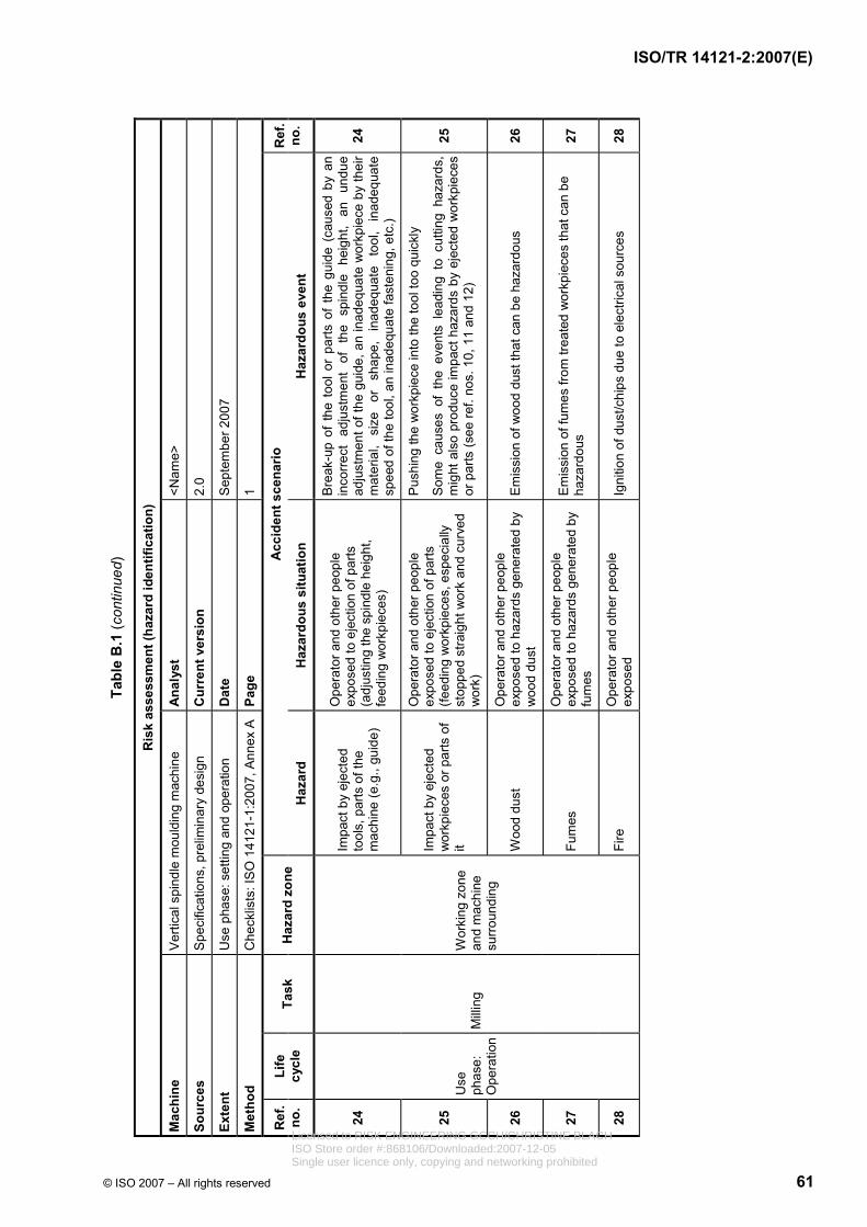
© ISO 2007 – All rights reserved 61
Tabl
e B
.1 (c
ontin
ued )
Ris
k as
sess
men
t (ha
zard
iden
tific
atio
n)
Mac
hine
V
ertic
al s
pind
le m
ould
ing
mac
hine
A
naly
st
<Nam
e>
Sour
ces
Spe
cific
atio
ns, p
relim
inar
y de
sign
C
urre
nt v
ersi
on
2.0
Exte
nt
Use
pha
se: s
ettin
g an
d op
erat
ion
Dat
e S
epte
mbe
r 200
7
Met
hod
Che
cklis
ts: I
SO
141
21-1
:200
7, A
nnex
A
Page
1
Acc
iden
t sce
nario
R
ef.
no.
Life
cy
cle
Task
H
azar
d zo
ne
Haz
ard
Haz
ardo
us s
ituat
ion
Haz
ardo
us e
vent
R
ef.
no.
24
Impa
ct b
y ej
ecte
d to
ols,
par
ts o
f the
m
achi
ne (e
.g.,
guid
e)
Ope
rato
r and
oth
er p
eopl
e ex
pose
d to
eje
ctio
n of
par
ts
(adj
ustin
g th
e sp
indl
e he
ight
, fe
edin
g w
orkp
iece
s)
Bre
ak-u
p of
the
tool
or
parts
of
the
guid
e (c
ause
d by
an
inco
rrect
ad
just
men
t of
th
e sp
indl
e he
ight
, an
un
due
adju
stm
ent o
f the
gui
de, a
n in
adeq
uate
wor
kpie
ce b
y th
eir
mat
eria
l, si
ze
or
shap
e,
inad
equa
te
tool
, in
adeq
uate
sp
eed
of th
e to
ol, a
n in
adeq
uate
fast
enin
g, e
tc.)
24
25
Impa
ct b
y ej
ecte
d w
orkp
iece
s or
par
ts o
f it
Ope
rato
r and
oth
er p
eopl
e ex
pose
d to
eje
ctio
n of
par
ts
(feed
ing
wor
kpie
ces,
esp
ecia
lly
stop
ped
stra
ight
wor
k an
d cu
rved
w
ork)
Pus
hing
the
wor
kpie
ce in
to th
e to
ol to
o qu
ickl
y
Som
e ca
uses
of
the
even
ts l
eadi
ng t
o cu
tting
haz
ards
, m
ight
als
o pr
oduc
e im
pact
haz
ards
by
ejec
ted
wor
kpie
ces
or p
arts
(see
ref.
nos.
10,
11
and
12)
25
26
Woo
d du
st
Ope
rato
r and
oth
er p
eopl
e ex
pose
d to
haz
ards
gen
erat
ed b
y w
ood
dust
E
mis
sion
of w
ood
dust
that
can
be
haza
rdou
s 26
27
Fum
es
Ope
rato
r and
oth
er p
eopl
e ex
pose
d to
haz
ards
gen
erat
ed b
y fu
mes
Em
issi
on o
f fum
es fr
om tr
eate
d w
orkp
iece
s th
at c
an b
e ha
zard
ous
27
28
Use
ph
ase:
O
pera
tion
Mill
ing
Wor
king
zon
e an
d m
achi
ne
surr
ound
ing
Fire
O
pera
tor a
nd o
ther
peo
ple
expo
sed
Igni
tion
of d
ust/c
hips
due
to e
lect
rical
sou
rces
28
ISO/TR 14121-2:2007(E)
Licensed to RISK ENGINEERING GCCH/CHRISTINE BLACHISO Store order #:868106/Downloaded:2007-12-05Single user licence only, copying and networking prohibited

62 © ISO 2007 – All rights reserved
Tabl
e B
.1 (c
ontin
ued)
Ris
k as
sess
men
t (ha
zard
iden
tific
atio
n)
Mac
hine
V
ertic
al s
pind
le m
ould
ing
mac
hine
A
naly
st
<Nam
e>
Sour
ces
Spe
cific
atio
ns, p
relim
inar
y de
sign
C
urre
nt v
ersi
on
2.0
Exte
nt
Use
pha
se: s
ettin
g an
d op
erat
ion
Dat
e S
epte
mbe
r 200
7
Met
hod
Che
cklis
ts: I
SO
141
21-1
:200
7, A
nnex
A
Page
1
Acc
iden
t sce
nario
R
ef.
no.
Life
cy
cle
Task
H
azar
d zo
ne
Haz
ard
Haz
ardo
us s
ituat
ion
Haz
ardo
us e
vent
R
ef.
no.
29
Wor
king
zon
e an
d m
achi
ne
surr
ound
ing
Slip
ping
and
fallin
g W
orki
ng a
t/with
the
mac
hine
S
lippi
ng o
n du
st- o
r chi
p-co
vere
d flo
or
29
30
N
oisy
man
ufac
turin
g pr
oces
s O
pera
tor a
nd o
ther
peo
ple
expo
sed
to h
azar
ds g
ener
ated
by
nois
e.
Em
issi
on o
f a le
vel o
f noi
se th
at c
an b
e ha
zard
ous
30
31
M
uscu
losk
elet
al
diso
rder
Fe
edin
g w
orkp
iece
s P
ainf
ul a
nd ti
ring
post
ure
due
to e
xces
sive
wei
ght o
f th e
w
orkp
iece
31
32
Use
ph
ase:
O
pera
tion
Mill
ing
Mac
hine
fram
e P
arts
whi
ch h
ave
beco
me
live
unde
r fau
lt co
nditi
ons
Wor
k w
ith a
mac
hine
und
er
volta
ge
Indi
rect
con
tact
32
ISO/TR 14121-2:2007(E)
Licensed to RISK ENGINEERING GCCH/CHRISTINE BLACHISO Store order #:868106/Downloaded:2007-12-05Single user licence only, copying and networking prohibited
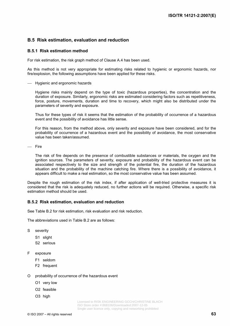
ISO/TR 14121-2:2007(E)
© ISO 2007 – All rights reserved 63
B.5 Risk estimation, evaluation and reduction
B.5.1 Risk estimation method
For risk estimation, the risk graph method of Clause A.4 has been used.
As this method is not very appropriate for estimating risks related to hygienic or ergonomic hazards, nor fire/explosion, the following assumptions have been applied for these risks.
⎯ Hygienic and ergonomic hazards
Hygiene risks mainly depend on the type of toxic (hazardous properties), the concentration and the duration of exposure. Similarly, ergonomic risks are estimated considering factors such as repetitiveness, force, posture, movements, duration and time to recovery, which might also be distributed under the parameters of severity and exposure.
Thus for these types of risk it seems that the estimation of the probability of occurrence of a hazardous event and the possibility of avoidance has little sense.
For this reason, from the method above, only severity and exposure have been considered, and for the probability of occurrence of a hazardous event and the possibility of avoidance, the most conservative value has been taken/assumed.
⎯ Fire
The risk of fire depends on the presence of combustible substances or materials, the oxygen and the ignition sources. The parameters of severity, exposure and probability of the hazardous event can be associated respectively to the size and strength of the potential fire, the duration of the hazardous situation and the probability of the machine catching fire. Where there is a possibility of avoidance, it appears difficult to make a real estimation, so the most conservative value has been assumed.
Despite the rough estimation of the risk index, if after application of well-tried protective measures it is considered that the risk is adequately reduced, no further actions will be required. Otherwise, a specific risk estimation method should be used.
B.5.2 Risk estimation, evaluation and reduction
See Table B.2 for risk estimation, risk evaluation and risk reduction.
The abbreviations used in Table B.2 are as follows:
S severity
S1 slight S2 serious
F exposure
F1 seldom F2 frequent
O probability of occurrence of the hazardous event
O1 very low
O2 feasible
O3 high Licensed to RISK ENGINEERING GCCH/CHRISTINE BLACHISO Store order #:868106/Downloaded:2007-12-05Single user licence only, copying and networking prohibited

ISO/TR 14121-2:2007(E)
64 © ISO 2007 – All rights reserved
A possibility of avoidance
A1 possible A2 impossible
RI risk index: from 1 (min.) to 6 (max.)
NOTE 1 In the setting of the machine it is considered that hygienic hazards (wood dust, fumes and noise), as well as ergonomic hazards, are not significant because the exposure to these hazards is too low to produce any risk. Similarly, for fire/explosion and slipping hazards it is considered that the amount of wood dust produced when the machine is properly installed is too little to create a meaningful risk.
NOTE 2 Some protective measures indicated in Table B.2 would be the result of several iterations. For example, in ref. no. 12 it is proposed that the table hole be reduced by means of table rings; the additional requirement of soft material would be, in fact, the result of a second hazard identification in order to avoid the break-up of the tool in case of contact with the ring.
NOTE 3 In ref. no. 18 a demountable power feed unit is proposed as a protective measure. The iterative process of the risk assessment would require, taking into account the instructions given by its manufacturer, a further consideration of the potential hazards generated by this unit during the whole life cycle of the machine and, if necessary the taking of new risk reduction measures (e.g. appropriate interlocking between the control functions of the spindle unit and the power feed unit, provision of an emergency stop control, appropriate adjustment).
Licensed to RISK ENGINEERING GCCH/CHRISTINE BLACHISO Store order #:868106/Downloaded:2007-12-05Single user licence only, copying and networking prohibited
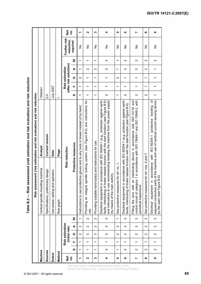
© ISO 2007 – All rights reserved 65
Tabl
e B
.2 —
Ris
k as
sess
men
t (ris
k es
timat
ion
and
risk
eval
uatio
n) a
nd ri
sk re
duct
ion
Ris
k as
sess
men
t (ris
k es
timat
ion
and
risk
eval
uatio
n) a
nd ri
sk re
duct
ion
Mac
hine
V
ertic
al s
pind
le m
ould
ing
mac
hine
A
naly
st
<Nam
e>
Sour
ces
Spe
cific
atio
ns, p
relim
inar
y de
sign
C
urre
nt v
ersi
on
2.0
Exte
nt
Use
pha
se: s
ettin
g an
d op
erat
ion
Dat
e Ju
ly 2
007
Met
hod
Ris
k gr
aph
Pa
ge
1
Ris
k es
timat
ion
(initi
al ri
sk)
Ris
k re
duct
ion
Ris
k es
timat
ion
(a
fter r
isk
redu
ctio
n)
Ref
. no
. S
F O
A
R
I Pr
otec
tive
mea
sure
s S
F O
A
R
I
Furt
her r
isk
redu
ctio
n re
quire
d
Ref
. no
.
1 1
1 2
2 1
Inst
ruct
ions
to u
se p
rote
ctiv
e gl
oves
and
to a
ny to
ols
in b
oxes
inst
ead
of b
y ha
nd.
1 1
2 1
1 N
o 1
2 1
1 3
2 2
Pro
vidi
ng a
n in
tegr
al s
pind
le l
ocki
ng s
yste
m (
see
Figu
re B
.5)
a nd
inst
ruct
ions
for
us
e.
1 1
1 2
1 N
o 2
3 1
1 3
2 2
Pro
vidi
ng s
uita
ble
hand
tool
(s) a
nd in
stru
ctio
ns fo
r use
. 1
1 1
2 1
No
3
4 2
1 2
2 3
Ele
ctric
al e
quip
men
t in
acco
rdan
ce w
ith IE
C 6
0204
-1 (
e.g.
, pro
tect
ion
agai
nst e
arth
fa
ults
, int
erlo
ckin
g of
bra
ke r
elea
se fu
nctio
n w
ith th
e st
art f
unct
ion)
(s e
e Fi
gure
B.6
) an
d in
stru
ctio
ns to
use
rec
omm
endi
ng is
olat
ing
the
mac
hine
from
the
pow
er s
uppl
y (b
y m
eans
of t
he m
ain
switc
h).
2 1
1 2
2 N
o 4
5 1
1 2
2 1
See
pro
tect
ive
mea
sure
s fo
r ref
. no.
1.
1 1
2 1
1 N
o 5
6 2
1 2
2 3
Ele
ctric
al e
quip
men
t in
acco
rdan
ce w
ith I
EC
602
04-1
(e.
g. p
r ote
ctio
n ag
ains
t ear
th
faul
ts, i
nter
lock
ing
of b
rake
rele
ase
func
tion
with
the
star
t fun
ctio
n (s
ee F
igur
e B
.6).
2 1
1 2
2 N
o 6
7 2
1 2
2 3
Fitti
ng t
he d
oor
with
an
inte
rlock
ing
devi
ce i
n ac
cord
ance
with
IS
O 1
4119
and
co
ntro
l circ
uit o
f cat
egor
y 1
in a
ccor
danc
e w
ith IS
O 1
3849
-1 a
nd IS
O 1
3849
-2, w
ith
perio
dica
l ins
pect
ions
. 2
1 1
2 2
No
7
8 2
1 2
2 3
See
pro
tect
ive
mea
sure
s fo
r ref
. nos
. 4 a
nd 7
. 2
1 1
2 2
No
8
9 2
1 2
2 3
Ele
ctric
al
equi
pmen
t in
ac
cord
ance
w
ith
IEC
602
04-1
(p
rote
ctiv
e bo
ndin
g of
ex
pose
d co
nduc
tive
parts
of t
he m
achi
ne a
nd u
se o
f res
idua
l cur
rent
sen
sing
dev
ice
by th
e us
er) (
see
Figu
re B
.6).
1 1
1 1
2 N
o 9
ISO/TR 14121-2:2007(E)
Licensed to RISK ENGINEERING GCCH/CHRISTINE BLACHISO Store order #:868106/Downloaded:2007-12-05Single user licence only, copying and networking prohibited
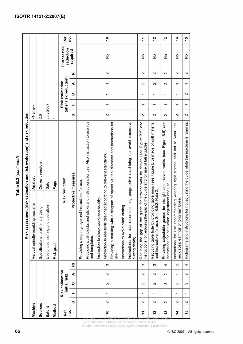
66 © ISO 2007 – All rights reserved
Tabl
e B
.2 (c
ontin
ued)
Ris
k as
sess
men
t (ris
k es
timat
ion
and
risk
eval
uatio
n) a
nd ri
sk re
duct
ion
Mac
hine
V
ertic
al s
pind
le m
ould
ing
mac
hine
A
naly
st
<Nam
e>
Sour
ces
Spe
cific
atio
ns, p
relim
inar
y de
sign
C
urre
nt v
ersi
on
2.0
Exte
nt
Use
pha
se: s
ettin
g an
d op
erat
ion
Dat
e Ju
ly 2
007
Met
hod
Ris
k gr
aph
Page
1
Ris
k es
timat
ion
(initi
al ri
sk)
Ris
k re
duct
ion
Ris
k es
timat
ion
(a
fter r
isk
redu
ctio
n)
Ref
. no
. S
F O
A
R
I Pr
otec
tive
mea
sure
s S
F O
A
R
I
Furt
her r
isk
redu
ctio
n re
quire
d
Ref
. no
.
10
2 1
2 2
3
Pro
vidi
ng a
dep
th g
auge
and
inst
ruct
ions
for u
se.
Pro
vidi
ng p
ush
bloc
ks a
nd s
ticks
and
inst
ruct
ions
for u
se. A
lso
inst
ruct
ion
to u
se ji
gs
and
tem
plat
es.
Inst
ruct
ion
to c
heck
wor
kpie
ce q
ualit
y.
Inst
ruct
ion
to u
se to
ols
desi
gned
acc
ordi
ng to
rele
vant
sta
ndar
ds.
Pro
vidi
ng a
mar
king
with
a d
iagr
am o
f spe
ed v
s. to
ol d
iam
eter
and
inst
ruct
ions
for
use.
Inst
ruct
ions
to a
void
clim
b cu
tting
.
Inst
ruct
ions
for
use
rec
omm
endi
ng p
rogr
essi
ve m
achi
ning
(to
avo
id e
xces
sive
cu
tting
dep
th).
2 1
1 1
2 N
o 10
11
2 1
2 2
3 R
educ
ing
the
gap
of t
he g
uide
for
stra
ight
wor
k by
des
ign
(see
Fig
ure
B.5
) an
d in
stru
ctio
ns fo
r red
ucin
g th
e ga
p of
the
guid
e an
d fo
r use
of f
alse
gu i
des.
2
1 1
2 2
No
11
12
2 1
2 2
3 R
educ
ing
tabl
e ho
le b
y pr
ovid
ing
tabl
e rin
gs (
see
Figu
re B
.5)
mad
e of
sof
t mat
eria
l an
d in
stru
ctio
ns fo
r use
. See
B.5
.2, N
ote
2.
2 1
1 2
2 N
o 12
13
2 1
3 2
4 P
rovi
ding
adj
usta
ble
guar
ds f
or s
traig
ht a
nd c
urve
d w
orks
(se
e Fi
gure
B.5
) an
d in
stru
ctio
ns fo
r ins
talla
tion,
adj
ustm
ent a
nd u
se.
2 1
1 2
2 N
o 13
14
2 1
2 1
2 In
stru
ctio
ns f
or u
se r
ecom
men
ding
wea
ring
tight
clo
thes
and
not
to
wea
r tie
s,
neck
lace
s, e
arrin
gs o
r lon
g ha
ir lo
ose.
2
1 1
1 2
No
14
15
2 1
3 2
4 P
icto
gram
s an
d in
stru
ctio
ns fo
r not
adj
ustin
g th
e gu
ide
whi
le th
e m
achi
ne is
runn
ing.
2 1
2 1
2 N
o 15
ISO/TR 14121-2:2007(E)
Licensed to RISK ENGINEERING GCCH/CHRISTINE BLACHISO Store order #:868106/Downloaded:2007-12-05Single user licence only, copying and networking prohibited
© ISO 2007 – All rights reserved 67
Tabl
e B
.2 (c
ontin
ued )
Ris
k as
sess
men
t (ris
k es
timat
ion
and
risk
eval
uatio
n) a
nd ri
sk re
duct
ion
Mac
hine
V
ertic
al s
pind
le m
ould
ing
mac
hine
A
naly
st
<Nam
e>
Sour
ces
Spe
cific
atio
ns, p
relim
inar
y de
sign
C
urre
nt v
ersi
on
2.0
Exte
nt
Use
pha
se: s
ettin
g an
d op
erat
ion
Dat
e Ju
ly 2
007
Met
hod
Ris
k gr
aph
Pa
ge
1
Ris
k es
timat
ion
(initi
al ri
sk)
Ris
k re
duct
ion
Ris
k es
timat
ion
(a
fter r
isk
redu
ctio
n)
Ref
. no
. S
F O
A
R
I Pr
otec
tive
mea
sure
s S
F O
A
R
I
Furt
her r
isk
redu
ctio
n re
quire
d
Ref
. no
.
16
2 1
2 2
3
Mak
ing
that
par
t of
the
gui
de c
lose
r to
the
too
l of
a so
ft m
ater
ial (
e.g.
ligh
t al
loy,
pl
astic
, woo
d).
Pro
vidi
ng a
n in
dica
tor o
f the
hei
ght o
f the
spi
ndle
nea
r the
hei
ght a
djus
tmen
t whe
el.
Inst
ruct
ions
for p
rope
r fas
teni
ng o
f the
tool
.
See
als
o pr
otec
tive
mea
sure
s fo
r ref
. no.
10.
2 1
1 2
2 N
o 16
17
1 1
3 2
2
Pro
vidi
ng in
the
guar
d a
“lead
-in” f
or c
urve
d w
ork
and
inst
ruct
ions
to u
se.
Pro
vidi
ng m
eans
to fi
x en
d st
ops.
Inst
ruct
ions
to u
se ji
gs a
nd e
nd s
tops
for s
topp
ed s
traig
ht w
ork.
See
als
o pr
otec
tive
mea
sure
s fo
r ref
. nos
. 10,
11
and
12.
1 1
1 2
1 N
o 17
18
2 2
2 2
5
Pro
vidi
ng a
dem
ount
able
pow
er f
eed
unit
for
stra
ight
wor
k (fo
r cl
arity
, it
is n
ot
repr
esen
ted
in F
igur
es B
.5 o
r Fig
ure
B.6
).
Pro
vidi
ng p
ush
bloc
ks a
nd s
ticks
and
inst
ruct
ions
to u
se th
em. A
lso,
inst
ruct
ions
to
use
jigs
and
tem
plat
es.
Inst
ruct
ions
for c
heck
ing
wor
kpie
ce q
ualit
y.
Inst
ruct
ions
to a
void
clim
b cu
tting
.
Inst
ruct
ions
for a
void
ing
inad
equa
te fe
edin
g sp
eed.
2 1
1 1
2 Ye
s (S
ee B
.5.2
, N
ote
3)
18
19
2 2
2 2
5 S
ee p
rote
ctiv
e m
easu
res
for r
ef. n
o. 1
1.
2 1
1 2
2 N
o 19
20
2 2
2 2
5 S
ee p
rote
ctiv
e m
easu
res
for r
ef. n
o. 1
2.
2 1
1 2
2 N
o 20
21
2 2
3 2
6 S
ee p
rote
ctiv
e m
easu
res
for r
ef. n
o. 1
3.
2 1
1 2
2 N
o 21
22
2 2
2 1
4 S
ee in
form
atio
n fo
r use
for r
ef. n
o. 1
4.
2 2
1 1
3 N
o 22
ISO/TR 14121-2:2007(E)
Licensed to RISK ENGINEERING GCCH/CHRISTINE BLACHISO Store order #:868106/Downloaded:2007-12-05Single user licence only, copying and networking prohibited

ISO/TR 14121-2:2007(E)
68 © ISO 2007 – All rights reserved
Tabl
e B
.2 (c
ontin
ued)
Ris
k as
sess
men
t (ris
k es
timat
ion
and
risk
eval
uatio
n) a
nd ri
sk re
duct
ion
Mac
hine
V
ertic
al s
pind
le m
ould
ing
mac
hine
A
naly
st
<Nam
e>
Sour
ces
Spe
cific
atio
ns, p
relim
inar
y de
sign
C
urre
nt v
ersi
on
2.0
Exte
nt
Use
pha
se: s
ettin
g an
d op
erat
ion
Dat
e Ju
ly 2
007
Met
hod
Ris
k gr
aph
Pa
ge
1
Ris
k es
timat
ion
(initi
al ri
sk)
Ris
k re
duct
ion
Ris
k es
timat
ion
(a
fter r
isk
redu
ctio
n)
Ref
. no
. S
F O
A
R
I Pr
otec
tive
mea
sure
s S
F O
A
R
I
Furt
her r
isk
redu
ctio
n re
quire
d
Ref
. no
.
23
2 1
3 2
4 In
terlo
ckin
g of
bra
ke r
elea
se f
unct
ion
with
the
sta
rt fu
nctio
n in
the
ele
ctric
al c
ircui
t (s
ee F
igur
e B
.6)
of c
ateg
ory
1, in
acc
orda
nce
with
IS
O 1
3849
-1 a
nd I
SO
138
49-2
, an
d in
stru
ctio
ns fo
r per
iodi
cally
che
ckin
g th
e br
akin
g tim
e.
2 1
2 1
2 N
o 23
24
2 2
2 2
5 S
ee p
rote
ctiv
e m
easu
res
for r
ef. n
o. 1
5 an
d al
so re
f. no
. 17.
2
2 1
2 4
No
24
25
1 2
3 2
2 S
ee p
rote
ctiv
e m
easu
res
for r
ef. n
o. 1
6 an
d al
so re
f. no
s. 1
7, 1
8 an
d 19
. 1
2 1
2 1
No
25
26
2 2
3 2
6 P
rovi
ding
out
lets
to
conn
ect
an e
xter
nal
dust
ext
ract
ion
syst
em w
ith a
min
imum
ai
rflow
of
1
500
m3
h−1
and
min
imum
co
nvey
ing
air
velo
city
of
20 m
s−1
(s
ee
Figu
re B
.5).
1 2
3 2
2 N
o 26
27
2 1
3 2
4
See
pro
tect
ive
mea
sure
s fo
r ref
. no.
24.
Inst
ruct
ions
for w
earin
g P
PE
.
Inst
ruct
ions
aga
inst
wor
king
trea
ted
woo
d or
sim
ilar m
ater
ials
.
1 1
3 2
2 N
o 27
28
1 2
2 1
2 E
lect
rical
equ
ipm
ent i
n ac
cord
ance
with
IEC
602
04-1
(min
imum
deg
ree
of p
rote
ctio
n IP
54,
dim
ensi
onin
g of
com
pone
nts,
suf
ficie
nt c
oolin
g, e
tc).
Inst
ruct
ions
to
use
the
dust
ext
ract
ion
syst
em.
1 2
1 1
1 N
o 28
29
1 2
2 2
1 In
stru
ctio
ns fo
r usi
ng th
e ex
haus
ting
syst
em a
nd c
lean
ing.
1
2 1
2 1
No
29
30
2 2
3 2
6 A
pply
ing
mea
sure
men
ts in
des
ign
to r
educ
e no
ise
at t
he s
ourc
e ( s
pind
le b
alan
ce,
bear
ings
, ant
i-vib
ratio
n m
ount
s, s
hiel
ding
). 1
2 3
2 2
No
30
31
1 2
3 2
2 P
rovi
ding
mac
hine
arr
ange
men
ts to
fix
exte
nsio
n ta
bles
. 1
1 3
2 2
No
31
32
1 2
2 2
1 S
ee p
rote
ctiv
e m
easu
res
for r
ef. n
o. 1
0.
1 2
2 1
1 N
o 32
Licensed to RISK ENGINEERING GCCH/CHRISTINE BLACHISO Store order #:868106/Downloaded:2007-12-05Single user licence only, copying and networking prohibited
ISO/TR 14121-2:2007(E)
© ISO 2007 – All rights reserved 69
Dimensions in millimetres
b) Guide with guard for straight work
c) Guide with guard for curved work
d) Rings for reducing table gaps Key 1 spindle locking system
Figure B.5 — Final design of the machine Licensed to RISK ENGINEERING GCCH/CHRISTINE BLACHISO Store order #:868106/Downloaded:2007-12-05Single user licence only, copying and networking prohibited
ISO/TR 14121-2:2007(E)
70 © ISO 2007 – All rights reserved
Figure B.6 — Final circuit diagram
Licensed to RISK ENGINEERING GCCH/CHRISTINE BLACHISO Store order #:868106/Downloaded:2007-12-05Single user licence only, copying and networking prohibited

ISO/TR 14121-2:2007(E)
© ISO 2007 – All rights reserved 71
Bibliography
[1] ISO 3691 (all parts)2), Industrial trucks — Safety requirements and verification
[2] ISO 10218-1, Robots for industrial environments — Safety requirements — Part 1: Robot
[3] ISO 11111 (all parts), Textile machinery — Safety requirements
[4] ISO 11161:2007, Safety of machinery — Integrated manufacturing systems — Basic requirements
[5] ISO/TR 11688-1, Acoustics — Recommended practice for the design of low-noise machinery and equipment — Part 1: Planning
[6] ISO 12100-1:2003, Safety of machinery — Basic concepts, general principles for design — Part 1: Basic terminology, methodology
[7] ISO 12100-2:2003, Safety of machinery — Basic concepts, general principles for design — Part 2: Technical principles
[8] ISO 13732-1, Ergonomics of the thermal environment — Methods for the assessment of human responses to contact with surfaces — Part 1: Hot surfaces
[9] ISO 13849-1, Safety of machinery — Safety-related parts of control systems — Part 1: General principles for design
[10] ISO 13849-2, Safety of machinery — Safety-related parts of control systems — Part 2: Validation
[11] ISO 13852, Safety of machinery — Safety distances to prevent danger zones being reached by the upper limbs
[12] ISO 14118, Safety of machinery — Prevention of unexpected start-up
[13] ISO 14119, Safety of machinery — Interlocking devices associated with guards — Principles for design and selection
[14] ISO 14120, Safety of machinery — Guards — General requirements for the design and construction of fixed and movable guards
[15] IEC 60204-1, Safety of machinery — Electrical equipment of machines — Part 1: General requirements
[16] IEC 61508 (all parts), Functional safety of electrical/electronic/programmable electronic safety-related systems
[17] EN 614-1, Safety of machinery — Ergonomic design principles — Part 1: Terminology and general principles
[18] EN 847-1, Tools for woodworking — Safety requirements — Part 1: Milling tools, circular saw blades
[19] EN 848-1, Safety of woodworking machines — One side moulding machines with rotating tool — Part 1: Single spindle vertical moulding machines
[20] ANSI B11 TR3:2000, Risk Assessment and Risk Reduction — A Guideline to Estimate, Evaluate and Reduce Risks Associated with Machine Tools
2) To be published. (Revision of ISO 3691:1980)
Licensed to RISK ENGINEERING GCCH/CHRISTINE BLACHISO Store order #:868106/Downloaded:2007-12-05Single user licence only, copying and networking prohibited

ISO/TR 14121-2:2007(E)
ICS 13.110 Price based on 71 pages
© ISO 2007 – All rights reserved
Licensed to RISK ENGINEERING GCCH/CHRISTINE BLACHISO Store order #:868106/Downloaded:2007-12-05Single user licence only, copying and networking prohibited


![Information technology — Programming languages — C++ · 2018-09-28 · INCITS/ISO/IEC 14882-2011[2012] PDF disclaimer This may contain embedded typefaces. In accordance with Adobe's](https://img.pdfslide.net/doc/110x75/5e693d4cab5a1510c11559ab/information-technology-a-programming-languages-a-c-2018-09-28-incitsisoiec.jpg)