Embed Size (px)
Citation preview
Project NO. 90-761 FV^VV Paul C. Rizzo Associates,March 1993 i. V - -^_ CONSULTANTS
rS
\_y
Part: 2Slug Testing;
Revised Sampling and Analysis Plan Background sou sampi
Remedial Investigation/Feasibility Study
Barceloneta Landfill SiteBarrio Florida AfueraBarceloneta, Puerto Rico
Prepared for:Barceloneta Landfill SitePRP Group
360001
n
REVISED SAMPLING AND ANALYSIS PLAN - PART 2SLUG TESTING; BACKGROUND SOIL SAMPLING
BARCELONETA LANDFILL SITEBARRIO FLORIDA AFUERA
BARCELONETA, PUERTO RICO
nPROJECT No. 90-761
MARCH 30,1993
PAUL C. Rizzo ASSOCIATES300 OXFORD DRIVE
MONROEVILLE, PENNSYLVANIA 15146TELEPHONE: (412)856-9700
TELEFAX: (412)856-9749 A*^300002r34-761/93
TABLE OF CONTENTS
PAGE
LIST OF TABLES...................................................................................................^LIST OF FIGURES.................................................................................................^
1.0 INTRODUCTION...................................................................................1-11.1 SAMPLING AND ANALYSIS OBJECTIVES.... . . . . . . . . . . . . . . . . . . . . . . . . . . . . . . . . . 1-11.2 FORMAT.................................................................................... 1-21.3 ABBREVIATIONS AND CONVENTIONS......... ................................. 1-2
2.0 SITE HISTORY AND DESCRIPTION.......................................... ........ 2-12.1 LOCATION.................................................................................. 2-12.2 OPERATIONAL AND REGULATORY HISTORY................................2-12.3 . SITE DESCRIPTION...................................................................... 2-22.4 PHASEI INVESTIGATION.............................................................2-2
2.4.1 Field Activities.........................................................2-22.4.2 Findings................................................................... 2-3
2.4.2.1 Geology/Hydrogeology......................... 2-32.4.2.2 Analytical Results..................................2-4
3.0 OBJECTIVES......................................................................................... 3-1
4.0 PROJECT ORGANIZATION........................... ......................................4-14.1 PROJECT LIAISON.......................................................................4-14.2 PRINCIPAL-IN-CHARGE..............................................................4-14.3 PROJECT MANAGER...................................................................4-24.4 QUALITY ASSURANCE OFFICER..................................................4-34.5 HEALTH AND SAFETY COORDINATOR.........................................4-34.6 FIELD SUPERVISOR..................................................................... 4-34.7 LABORATORY PERSONNEL .....................................-:...............'....4-44.8 DATA VALIDATION PERSONNEL.................................................. 4-44.9 TECHNICAL AND SUPPORT STAFF...............................................4-5
( 4.10 SUBCONTRACTORS.....................................................................4-5;
1 r3-toc-761/93 i
300003
n( :
TABLE OF CONTENTS(Continued)
PAGE
5.0 QUALITY ASSURANCE OBJECTIVES FOR MEASUREMENTDATA........................ ............................................................................. 5-15.1 PRECISION. . . . . . . . . . . . . . . . . . . . . . . . . . . . . . . . . . . . . . . . . . . . . . . . . . . . . . . . . . . . . . . . . . . . . . . . . . . . . . . . . 5-15.2 ACCURACY........... .................................................................. ...5-15.3 COMPLETENESS........................................................ .................. 5-15.4 REPRESENTATIVENESS................................................................ 5-25.5 COMPARABILITY.. ..................................................................... .5-2
6.0 FIELD INVESTIGATION PROCEDURES . . . . . . . . . . . . . . . . . . . . . . . . . . . . . . . . . . . . . . . . . . . 6-16.1 GENERAL DOCUMENTATION REQUIREMENTS...... ........................ 6-16.2 DATASECURITY SYSTEM............................................... ............ 6-26.3 DRILLING AND SAMPLING OF BACKGROUND SOIL BORINGS ........ 6-36.4 SLUG TESTING OF MONITORING WELLS ...................................... 6-46.5 Am MONITORING.. ..................................................................... 6-56.6 SAMPLE PREPARATION AND HANDLING.................... .................. 6-6
6.6.1 Sample Containers.......................... .......................... 6-66.6.2 Sample Preservation and Holding Times ................... 6-66.6.3 Sample Shuttles.......... .............................................. 6-76.6.4 Sample Labeling and Handling.................................. 6-86.6.5 Sample Receipt ........................................................6-9
6.7 DECONTAMINATION. ............................................................ ....6-106.7.1 Personnel . . . . . . . . . . . . . . . . . . . . . . . . . . . . . . . . . . . . . . . . . . . . . . . . . . . . . . . . . . . . . . . 6-106.7.2 Small Tools and Equipment. . . . . . . . . . . . . . . . . . . . . . . . . . . . . . . . . . . . 6-106.7.3 Large Equipment.. . . . . . . . . . . . . . . . . . . . . . . . . . . . . . . . . . . . . . . . . . . . . . . . . . . 6-11
6.8 EXTENT OF SUPERFUND DISPOSAL AREA. ................................. 6-12
7.0 SAMPLE C U S T O D Y . . . . . . . . . . . . . . . . . . . . . . . . . . . . . . . . . . . . . . . . . . . . . . . . . . . . . . . . . . . . . . . . . . . . . . . . . . . . . 7-17.1 FIELD PROCEDURES ....... . . . . . . . . . . . . . . . . . . . . . . . . . . . . . . . . . . . . . . . . . . . . . . . . . . . . . . . . . . . . 7-17.2 LABORATORY PROCEDURES................. ...................................... 7-2
r3-Uw-761/93 11300004
TABLE OF CONTENTS(Continued)
PAGE
8.0 CALIBRATION P R O C E D U R E S . . . . . . . . . . . . . . . . . . . . . . . . . . . . . . . . . . . . . . . . . . . . . . . . . . . . . . . . . . . . 8 - 18.1 ANALYTICAL REFERENCE STANDARDS....................................... 8-18.2 DOCUMENTATION...................................................................... 8-2
8.2.1 Field Documentation................................................8-28.2.2 Laboratory Documentation....................................... 8-2
9.0 ANALYTICAL PROCEDURES ............................................................. 9-19.1 .CHEMICAL PARAMETERS....... . . . . . . . . . . . . . . . . . . . . . . . . . . . . . . . . . . . . . . . . . . . . . . . . . . . . . 9-19.2 GEOTECHNICAL PARAMETERS.................................................... 9-19.3 REPORTING................................................................................ 9-1
10.0 QUALITY CONTROL.......................................................................... 10-110.1 FIELD DUPLICATE SAMPLES...................................................... 10-110.2 EQUIPMENT BLANKS ................................................................ 10-210.3 LABORATORY INORGANIC QUALITY CONTROL.......................... 10-2
10.3.1 Method Blanks....................................................... 10-210.3.2 Calibration Check Standard.................................... 10-210.3.3 ICP Interference Check Sample.............................. 10-310.3.4 ICP Serial Dilution Analysis ................................... 10-3
' 10.3.5 Spiked Sample Analysis.......................................... 10-310.3.6 Laboratory Duplicate Sample Analysis.................... 10-3
11.0 DATA GENERATION, FLOW, VALIDATION, AND REPORTING ..11-111.1 DATA GENERATION AND DATA FLOW....................................... 11-111.2 DATA VALIDATION AND ASSESSMENT.. .................................... 11-3
11.2.1 Inorganic Method Blank Analysis........................... 11-411.2.2 ICP Interference Check Sample.............................. 11-411.2.3 ICP Serial Dilution Analysis................................... 11-511.2.4 Spiked Sample Analysis.......................................... 11-5
* 11.2.5 Laboratory Duplicate Sample Analysis.................... 11-5• 11.2.6 Equipment Blanks.................................................. 11-6v r3-toc-761/93 Hi
300005
TABLE OF CONTENTS(Continued)
PAGE
11.2.7 Field Duplicate Samples......................................... 11-611.2.8 Holding Time......................................................... 11-6
11.3 DATA REPORTING.................................................................... 11-611.3.1 Qualifiers................................................................ 11-711.3.2 Data Reporting System........................................... 11-7
12.0 PREVENTATIVE MAINTENANCE.................................................... 12-112.1 LABORATORY PROCEDURES..................................................... 12-1
12.1.1 Preventative Maintenance Schedules....................... 12-112.1.2 Replacement Parts.................................................. 12-112.1.3 Record Keeping and Preventative
Maintenance Logbooks .......................................... 12-212.2 FIELD PROCEDURES ................................................................. 12-2
13.0 SPECIFIC ROUTINE PROCEDURES USED TO ASSESS DATAPRECISION, ACCURACY, AND COMPLETENESS.......................... 13-113.1 PRECISION............................................................................... 13-113.2 ACCURACY.............................................................................. 13-213.3 COMPLETENESS........................................................................ 13-2
14.0 NONCONFORMANCE/CORRECTIVE ACTION................................ 14-114.1 NONCONFORMANCE................................................................. 14-114.2 CORRECTIVE ACTION............................................................... 14-2
REFERENCESTABLESFIGURESAPPENDIX A - ETC LABORATORY QUALITY ASSURANCE PLANAPPENDIX B - BLANK FIELD FORMS AND LOGSAPPENDIX C - TARGET COMPOUND LIST/TARGET ANALYTE LIST ' 300006
r3-toc-761/93 iV
LIST OF TABLES
TABLE NO.
4-1
5-1
9-1
9-2
TITLE
ADDRESSES AND PHONE NUMBERS OF PROJECTKEY INDIVIDUALS
PRECISION, ACCURACY, AND COMPLETENESSOBJECTIVES
SAMPLE SUMMARY
ANALYTICAL METHODS
LIST OF FIGURES
FIGURE NO.
2-1
2-2
4-1
4-2
6-1
TITLE
SITE LOCATION MAP
SITE PLAN MAP
INTERNAL PROJECT ORGANIZATION CHART
EXTERNAL PROJECT ORGANIZATION CHART
PROPOSED BACKGROUND SOUL SAMPLINGLOCATIONS
300007
r3-toc-761/93
REVISED SAMPLING AND ANALYSIS PLAN - PART 2BARCELONETA LANDFILL SITE
BARRIO FLORIDA AFUERABARCELONETA, PUERTO RICO
1.0 INTRODUCTION
Paul C. Rizzo Associates has been retained by the potentially responsible parties (PRPs) toperform a Remedial Investigation/Feasibility Study (RI/FS) at the Barceloneta Landfill Site(the site) in Barrio Florida Afuera, Barceloneta, Puerto Rico. The RI/FS will be preparedand performed pursuant to the Administrative Order on Consent, II CERCLA-00304(Consent Order), which was entered into by the United States Environmental ProtectionAgency Region II (USEPA) and the respondent PRPs. The RI/FS will utilize theUSEPA-approved Work Plan (NUS, 1990) as applicable. The Revised Sampling andAnalysis Plan follows the original SAP (Paul C. Rizzo Associates, 199la), amended byrevisions that were discussed previously with USEPA. At the request of USEPA, theRevised SAP has been submitted as two documents. This document is Part 2 of theRevised SAP (Revised SAP (2)).
1.1 SAMPLING AND ANALYSIS OBJECTIVES
The Revised SAP (2) focuses on sampling and analysis requirements for background soils inthe vicinity of the site, and slug testing of the eight monitoring wells. One purpose of theRevised SAP (2) is to provide a detailed description of soil sample collection procedures,sample analysis procedures, data quality objectives, and data analysis processes necessary toprovide chemical concentration data for site characterization. This plan is designed to beconsistent with the sampling and analysis methods described in the USEPA publication,"Test Methods for Evaluating Solid Waste," (SW-846) (USEPA, 1986). The contents ofthe Revised SAP (2) are consistent with the requirements of SW-846, the USEPA ContractLaboratory Program (CLP), and "Data Quality Objectives for Remedial Response Activities
300008r3-l-761/93 1-1
Development Process" (DQO Guidance) (USEPA, 1987). Another purpose of the RevisedSAP (2) is to better characterize the groundwater flow regime in the shallow portion of theaquifer through slug testing. The data generated under the Revised SAP (2) will beincorporated into the Remedial Investigation (Rl) Report.
1.2 FORMAT
The format of this SAP is designed to present the sampling and analysis process in achronological manner. Section 1.0 provides a brief introduction. A description of the siteand its history can be found in Section 2.0. Section 3.0 states the objectives of theRevised SAP (2) and Section 4.0 describes the project organization. Quality assuranceobjectives are discussed in Section 5.0. The field investigation procedures are detailed inSection 6.0. Section 7.0 describes sample custody. Calibration procedures and analyticalprocedures are provided in Sections 8.0 and 9.0, respectively. Section 10.0 describesquality control. Information regarding data generation, data flow, data validation and datareporting is found in Section 11.0. Preventative maintenance procedures are discussed inSection 12.0. Procedures used to assess the precision, accuracy, and completeness of dataare detailed in Section 13.0. Section 14.0 describes the reporting of and the correctiveactions to be taken in the event of nonconformances. Tables and figures are providedfollowing the text. Additional data or procedures which supplement the text are providedin Appendices A through C.
1.3 ABBREVIATIONS AND CONVENTIONS
Abbreviations for certain terms which are used frequently in the text include the following:
• Mean Sea Level MSL• Contract Laboratory Program CLP• Health and Safety Plan HSP• National Priorities List NPL• Potentially Responsible Party PRP• Remedial Investigation/Feasibility Study RI/FS
300009
r3-l-761/93 1-2
• Sampling and Analysis Plan SAP• Statement of Work SOW• Target Analyte List TAL• United States Geologic Survey USGS
300010r3-l-761/93 1-3
2.0 SITE HISTORY AND DESCRIPTION
2.1 LOCATION
The Barceloneta Landfill site is located near the north coast of Puerto Rico, about 9 kilometerssouth of the Atlantic Ocean (Figure 2-1). Situated in Barrio Florida Afuera, the site is 4.5kilometers south of Barceloneta, and approximately 60 kilometers west of San Juan. It islocated in an area of dense tropical vegetation and karst geomorphology characterized by thepresence of sinkholes (sumideros) which are surrounded by limestone hills known as "mogotes."Three of these sinkholes make up the three waste disposal areas as shown on Figure 2-2.
2.2 OPERATIONAL AND REGULATORY HISTORY
The 32.6 hectare piece of land where the Barceloneta Landfill now exists was purchased by theMunicipality of Barceloneta as three separate parcels during the early 1970's. The landfillbegan operation in August 1973 and over the course of operations, three sinkholes totaling anarea of approximately six hectares were filled with waste. The landfill was permitted to receivemunicipal waste, and also received industrial waste that was subject to approval. Throughoutits operation, the landfill has been inspected by the Puerto Rico Environmental Quality ControlBoard and the Department of Health. The majority of these inspections cited variousviolations of solid waste management and health regulations.
The southern-most sinkhole was the first used first for waste disposal. It received the mostindustrial waste and is known locally as "El Superfund," and is identified on Figure 2-2 as the"Superfund" Disposal Area. Tropical plant growth has revegetated most of this area. Thenorthern sinkhole, identified on Figure 2-2 as the Northern Disposal Area, was used next. Thisarea is usually inactive, but waste is still occasionally placed on top of the cover material. Grassand small shrubs are growing on about two-thirds of the Northern Disposal Area. The south-eastern sinkhole (Southeastern Disposal Area) is currently active and is being filled with waste.
According to the Work Plan, in September 1981 a USEPA sampling team collected samples ofsurface water ponded at the site, and the analytical results indicated the presence of hazardoussubstances. Subsequently, the Barceloneta Landfill Site was proposed for inclusion on the
300011r3-2-761/93 2-1
DOC
National Priorities List (NPL) in December 1982 and was listed as an NPL site in September1983. The site is Number 454 out of 1,067 sites on the NPL updated as of August 1992.
2.3 SITE DESCRIPTION
As mentioned, each waste disposal area consists of a sinkhole surrounded by steep limestonehills. The slopes of the active southeastern sinkhole and the "Superfund" sinkhole expose theAguada Limestone overlaid by Aymamon Limestone. The walls of the sinkhole to the northexpose only the Aymamon. Because of the high permeability of the limestone and the fact thatthe waste disposal areas are surrounded by hills, there are no surface drainage features. In fact,the sinkholes act as basins that collect rain water. There are two basic pathways for water toescape the sinkholes: evapotranspiration; and infiltration downward through blanket sands andlimestone. Because of the tropical temperatures and lush vegetative growth in the sinkholes(where present), evapotranspiration is probably a significant route of water loss. As there is nosurface runoff leaving the sinkholes, all water not lost through evapotranspiration must passthrough the waste into the subsurface.
^Because of the importance of the underlying aquifers and the high permeability of thelimestone, the medium given the greatest attention during the 1992 field investigation (referredto herein as Phase I) was groundwater. Soil was also a medium of interest, and soil samplesfrom the site were sent for chemical analysis during the Phase I investigation. The results ofthese analyses are detailed in the Site Characterization Summary Report (SCSR) (Paul C.Rizzo Associates, 1992) and briefly summarized in Section 2.4.2.
2.4 PHASE I INVESTIGATION
2.4.1 Field Activities
The Phase I field investigation, described in the SCSR, was conducted at the BarcelonetaLandfill Site from January 1992 to June 1992. It is described in the Site CharacterizationSummary Report (Paul C. Rizzo Associates, 1992). Activities conducted during Phase I are asfollows:
—^ • Eight monitoring wells were installed on and adjacent to the site. f
300012r3-2-761/93 2-2
• The eight monitoring wells were developed.
• Two borings were made through each of the three wastedisposal areas. Where present (five of the six subwaste borings),soil from immediately below the waste was sampled forlaboratory analysis. A small amount of leachate was detected inonly one of the six subwaste borings; this sample also wascollected for laboratory analysis.
• Six soil borings were made outside of the waste disposal areas.Ample soil for laboratory analysis was collected from four ofthese borings.
• Two rounds of groundwater samples were collected from themonitoring wells for laboratory analysis.
• A topographic site survey was conducted.
• A spring survey was conducted. Only one spring was found.A sample from this spring, the Ojo de Guillo, was collectedfor laboratory analysis.
2.4.2 Findings
2.4.2.1 Geology/Hydrogeology
The site geology is characterized by three distinct lithologic units (from youngest to oldest):the Aymamon Limestone, the Aguada Formation, and the Cibao Formation. Monitoring wellsMW-1 through MW-3 are entirely within the Aguada Formation while wells MW-4 throughMW-8 penetrate both the Aymamon Limestone and the Aguada Formation. All monitoringwells at the site are screened in the Aguada Formation. The Aguada Formation is a veryheterogeneous unit that was found to contain a distinct, laterally continuous marker horizon.This marker horizon is composed of a clay-rich, green marl which was used for correlationacross the site (referred to here as the "Green Marl"). The Green Marl was used to determinethe geologic structure (or attitude) of the units found at the site which is thought to coincidewith the regional structure. The rocks have a strike of N79°W with a dip of 3.7° to the north-northeast.
300013r3-2-761/93 2-3
The objective of the Phase I monitoring well program was to install the wells in the first water-bearing unit below the site. The first water-bearing unit was originally expected to be theregional water table. It was discovered during monitoring well installation that the Green Marlwas a very low permeability unit (aquitard). A perched water zone was found to exist on topof the Green Marl near the central and northern portions of the site. Therefore, monitoringwells MW-4 through MW-8 were screened across the Green Marl. At the southern portion ofthe site, perched water was not evident above the Green Marl and monitoring wells MW- 1through MW-3 were screened across the regional water table.
The upper perched zone has a fairly steep hydraulic gradient that is approximately equal to thedip of the bedding at the site. The deeper unconfined aquifer tends to have a lower hydraulicgradient which tends to cut across lithology. Based on review of ground water elevations inthe monitoring wells as well as the location and attitude of the Green Marl, the perched watertable appears to merge with the unconfined regional water table in the northern portion of thesite. Monitoring wells MW-7 and MW-8 are located in the vicinity where the perched watertable and the regional water table are likely to merge. Therefore, wells MW-7 and MW-8probably intercept groundwater flowing from the coalesced perched and regional water tables—^which underlie the site.
2.4.2.2 Analytical Results
During Phase I, few organic compounds were detected in two rounds of groundwater samples.Three volatile organic compounds, chloroform, 1,1-dichloroethene (1,1-DCE), andtrichloroethene (TCE) were detected at low concentrations in each of the two samplingrounds. The maximum detected levels of chloroform (12 ug/1) and TCE (3 ug/1) were less thanthe respective drinking water maximum contaminant levels (MCLs) of 100 ug/1 and 5 ug/1,respectively. The detected concentrations of 1,1-DCE exceeded the MCL (7 ug/1), althoughonly slightly in the second round (1 1 ug/1).
It is noted that the three chlorinated organic compounds detected in groundwater are regardedas dense-non-aqueous-phase-liquids (DNAPLs). Because DNAPLs are of low solubility andhave a higher specific gravity than that of water, they tend to sink and form layers of pureproduct. Therefore, higher concentrations of DNAPLs would be expected at the base of anaquifer.
300014r3-2-761/93 2-4
The Green Marl is a low permeability unit that serves as the base of the perched aquifer asdescribed in Section 2.4.2.1. TCE (3 ug/1) and chloroform (12 ug/1) were detected inMonitoring Well MW-6, and TCE (2 ug/1), only, was detected in MW-5. Both of these wellsare screened across the Green Marl. Because groundwater samples were collected from thebottom of the perched aquifer, the greatest concentrations of DNAPLs would be representedby these samples. As described above, the concentrations of chlorinated organics detected inthese wells are low. Therefore, DNAPLs have not been measured at the base of the perchedaquifer and are not likely to exist at this site.
The pesticide Endosulfan 1 was detected at very low concentrations (0.12 ug/1; 0.15 ug/1) inthe Phase I Round 2 sample from Monitoring Well MW-7. Although no MCL exists for thispesticide, the detected concentrations were below the proposed RCRA action levels (2 ug/1) byover an order of magnitude. No semivolatile organic compound was detected in any of thePhase I groundwater samples. Neither were any organic compounds detected in the singlespring sample collected from the Ojo de Guillo.
The concentrations of both inorganic parameters and total suspended solids (TSS) wereinconsistent between sampling rounds during Phase I. Further, there was a high correlationbetween concentrations of inorganics and TSS. It appears that the elevated levels ofinorganics observed in some of the groundwater samples are associated with suspendedmaterial. Therefore, actual concentrations of inorganic parameters in groundwater remainuncertain. The concentration of each inorganic parameter in the spring sample was relativelylow and easily within a background concentration range.
The groundwater regime will be further characterized by slug testing to be performed on allmonitoring wells as described in Section 6.4, and by the collection of additional groundwatermeasurements as described in both parts of the Revised SAP. Slug testing will provideinformation on the local transmissivity of the formations. The variations in transmissivity willhelp us to further evaluate groundwater flow direction and rate within the site. The slugtesting data should be reviewed before a determination is made regarding the number andlocations of additional monitoring wells, if any are necessary.
With regard to soil samples collected from below the waste, only acetone was confirmed asdetected. However, acetone was also detected in equipment blanks and method blanks,.,suggesting that the soil sample results may have been influenced by laboratory or field
300015r3-2-761/93 2-5
contamination. The measured levels of acetone are not of concern to human health (even if anexposure pathway existed). Five semivolatile organic compounds were detected from amongthe subwaste soil samples. These include bis(2-ethylhexyl) phthalate, benzyl butyl phthalate,phenol, 2-methylphenol, and 4-methylphenol.
1,1,1-Trichloroethane (260 ug/kg) was detected in a sample from a boring located adjacent tothe Superfund Disposal Area, and low levels of benzene (4 ug/kg), chlorobenzene (7 ug/kg),and xylene (12 ug/1) were detected in a sample from a soil boring isolated from the wastedisposal areas. No pesticides were detected in any of the soil samples.
In six borings into the waste, no leachate was found in five of them and only a small amount ofleachate was encountered in the sixth. Therefore, it is apparent that only a small amount ofleachate is present in the three disposal areas. The single leachate sample exhibited lowconcentrations of four volatile organics: benzene (14 ug/1), chlorobenzene (87 ug/1),ethylbenzene (44 ug/1), and xylene (49 ug/1).
With regard to inorganics, appropriate site-specific background soil concentration ranges couldnot be established during Phase I. Therefore, determinations could not be made regardingwhich inorganic parameters, if any, exceeded site-specific background ranges. The collectionof additional background soil samples is necessary before such determinations can be made.
300016
* - r3-2-761/93 2-6
3.0 OBJECTIVES
The objectives of the investigation described in the Revised SAP (2) are as follows:
• To further characterize the perched water table and theregional unconfmed aquifer by slug testing eachmonitoring well, and obtaining an additional round ofgroundwater levels.
• To collect an adequate number of background soilsamples, so that site-specific background ranges may becalculated for the TAL parameters. These will enable acomparison of the concentrations of inorganicconstituents in the Phase I soil samples to those inbackground soils.
• To better delineate the extent of the Superfund DisposalArea, through visual observations of the surface and bymaking shallow borings to search for waste.
These objectives are part of the overall RJ/FS project objectives of identifying andevaluating a range of site remediation alternatives, including, but not limited to,containment, material recycling, in-place treatment, and removal followed by treatment.
300017r3-3-761/93 3-1
4.0 PROJECT ORGANIZATION
The Barceloneta Landfill Site PRPs (PRP Group) have retained Paul C. Rizzo Associatesto perform an RI/FS utilizing the USEPA Work Plan and the original SAP (Paul C. RizzoAssociates, 1991). In order to perform the RI/FS efficiently, a clearly definedorganizational network has been developed. Effective communication and anunderstanding of responsibilities are absolutely necessary within the Paul C. RizzoAssociates project team. Equally imperative, Paul C. Rizzo Associates must establish andmaintain communication with the PRP Group, USEPA, and all subcontractors involvedwith the project. It is the goal of Paul C. Rizzo Associates to ensure that the BarcelonetaLandfill project progresses in an organized, timely, and cost-effective manner that fulfillsthe objectives of the Work Plan.
A description of the project organization and profiles of key project personnel areprovided in this section. Figure 4-1 depicts the organizational structure in regards to thePaul C. Rizzo Associates project team. Figure 4-2 shows the overall organizationalscheme and contacts with reference to the PRP Group, USEPA, subcontractors, as well asPaul C. Rizzo Associates. Table 4-1 lists the business addresses and telephone numbers ofthe individuals identified herein.
4.1 PROJECT LIAISON
Mr. Gordon V. Spradley of Browning-Ferns Industries, Inc. (BFI) has been designated asthe Project Liaison. He will be the PRP Group representative with whom the ProjectManager will have the most direct contact. Mr. Spradley will communicate with the otherparticipants of the PRP technical committee and the USEPA Project Manager, asnecessary.
4.2 PRINCrPAL-lN-CHARGE
Dr. Paul C. Rizzo is the Paul C. Rizzo Associates Principal-in-Charge for the site. Hisresponsibilities include:
r3-4-761/93 4-1
• Ensuring that sufficient resources are available to theproject team so that it can respond fully to therequirements of the site investigation.
• Providing direction and guidance to the ProjectManager as needed.
• Providing senior level review of technical activities.
Dr. Rizzo will also be available for direct contact with the participating PRPs andregulatory agencies.
4.3 PROJECT MANAGER
Mr. Malcolm W. Petroccia is the Paul C. Rizzo Associates Project Manager for the site.He will be responsible for all technical, financial, and scheduling matters. Otherresponsibilities will include:
• Communication with the Project Liaison and theUSEPA Project Manager.
• Interaction with the sampling team, Quality AssuranceOfficer, and Health and Safety Officer to assure thatthese programs are functioning effectively.
• Approval of project-specific procedures and internallyprepared plans, drawings, and reports.
• Serving as the "collection point" for project staffreporting of nonconformances and changes in projectdocuments and activities.
For purposes of the Consent Order, Mr. Petroccia has also been designated as ProjectCoordinator by the PRP Group.
300019r3-»-761/93 4-2
4.4 QUALITY ASSURANCE OFFICER
Mr. Richard A. Brown will be the Paul C. Rizzo Associates Quality Assurance Officer forthe project. His responsibilities will include:
• Administration of the project Quality AssuranceProgram.
• Overall supervision of quality assurance activities.
• Notification of personnel of nonconformances andchanges in quality assurance procedures.
• Determination of an audit schedule, if needed.
The Project Manager will be responsible for day-to-day supervision of quality assuranceactivities. The Quality Assurance Officer reports to the Principal-in-Charge. He may actindependently from the Project Manager, if required, to effect compliance with theQA/QC Plan. He will provide the necessary guidance to the project and laboratory staffson quality-related matters and will initiate and maintain responsibility for project audits.He has the authority and freedom to identify quality problems; to initiate, recommend, orprovide corrective actions; and to verify the implementation of the corrective actions.
4.5 HEALTH AND SAFETY COORDINATOR
Ms. Beth Ann Jenkins is Health and Safety Coordinator for the project. Ms. Jenkins isresponsible for the development and implementation of the Health and Safety Plan (HSP)(Paul C. Rizzo Associates, 1991 b).
4.6 FIELD SUPERVISOR
Mr. Howard W. Gault, Assistant Project Geologist, will function as the Field Supervisor.Mr. Gault has extensive experience in conducting investigations in Puerto Rico and otherLatin American countries. He will oversee all drilling operations and all field sampling.Mr. Gault will also be responsible for the proper labeling of samples and followingchain-of-custody procedures in regard to the handling and the transporting of samples.
360020
r3-*-761/93 4-3
Additionally, he will be in charge of on-site data security (see Section 6.2). Mr. Gault willbe responsible for completion of a daily log of site activities. He will report to the ProjectManager by phone at least three times each week. Mr. Gault will be assisted by a samplingteam of two Paul C. Rizzo Associates engineers or scientists. Mr. Matthew J. Valentine,Project Geologist, will be available if additional geologic expertise is needed.
4.7 LABORATORY PERSONNEL
The key laboratory personnel for this project will be the Laboratory Project Manager andthe Laboratory Quality Assurance Officer The Laboratory Project Manager will beresponsible for execution of the analytical testing program for the project. EnvironmentalTesting and Certification Corporation (ETC) has been selected to perform analyticaltesting for the project. The ETC laboratory to be used for this project is located inEdison, New Jersey. ETC quality assurance information appears in Appendix A.
4.8 DATA VALIDATION PERSONNEL
One or more qualified engineers or scientists will perform data validation for this project.Several Paul C. Rizzo Associates' technical staff members have considerable experience inUSEPA Contract Laboratory Program (CLP) data validation methodologies, including the1990 Standard of Practice (SOP) for organics and inorganics, and are also familiar withUSEPA Region II January 1992 revisions to the SOP. Paul C. Rizzo Associates hasperformed data validation for numerous Superfund projects. Under the supervision of theProject Manager, any of the following individuals may perform data validation for thisproject:
• Mr. James K. Griffiths, Assistant Project Scientist;• Ms. Beth Ann Jenkins, Assistant Project Scientist;• Mr. Bryan R. Maurer, Engineer; and• Mr. Thomas J. Siard, Assistant Project Scientist.
300021r3-4-761/93 4-4
4.9 TECHNICAL AND SUPPORT STAFF
Individuals in this category will participate in the technical activities associated with theproject. They will report to the Project Manager.
4.10 SUBCONTRACTORS
In addition to ETC, the analytical laboratory, Paul C. Rizzo Associates proposes thecontinued use of Geomega, Inc., as a consultant and GeoCim as the drilling contractor.Mr. Reginald P. Briggs is the President of Geomega, Inc. Mr. Briggs was one of theSenior Scientists of the USGS, and is the author of the geologic map for the BarcelonetaQuadrangle as well as other geologic maps for Puerto RJco. Several of his publicationsare referenced in the USEPA Work Plan for the RI/FS. He has also consulted recently onkarst issues at another NPL site in the vicinity of Barceloneta. Paul C. Rizzo Associateshas an ongoing professional relationship with Mr. Briggs and we are very pleased that heand Geomega, Inc., will continue to participate with us on this project. Likewise, GeoCimperformed excellent work during the Phase I investigation as well as in another project forPaul C. Rizzo Associates in the Barceloneta area.
300022*
r3-4-761/93 4-5
5.0 QUALITY ASSURANCE OBJECTIVESFOR MEASUREMENT DATA
The quality of data generated for this investigation can be characterized in terms ofprecision, accuracy, completeness, representativeness, and comparability. The qualityassurance (QA) objectives for accomplishing the investigation objectives for precision,accuracy, and completeness are indicated in Table 5-1. These data characteristics aredefined in the following subsections.
5.1 PRECISION
Precision is defined as a measure of mutual agreement among individual measurements ofthe same property, usually under prescribed similar conditions. Precision evaluationindicates whether the reproducibility of the analytical result is compromised due toanalytical techniques, sample matrix interferences, or other factors.
f~\
5.2 ACCURACYi
Accuracy is defined as the degree of agreement of a measurement (or an average ofmeasurements of the same thing) with an accepted reference or true value, usuallyexpressed as:
• The difference between the two values;• The percentage of the difference relative to the
reference or true value; or• The ratio of the difference to the reference or true value.
5.3 COMPLETENESS
Completeness is defined as a measure of the amount of valid data obtained from ameasurement system compared to the amount that was expected under normal conditions.To determine completeness, the percentage of valid (i.e., acceptable) data obtained, as
—^ judged by the precision and accuracy objectives, is compared to the total amount of data
30Q0231 r3-5-761/93 5-1
collected, resulting in a validation percent, Table 5-1 lists the completeness objectives foraccomplishing the investigation objectives. Section 13.0 provides a discussion ofprocedures to assess data completeness.
5.4 REPRESENTATIVENESS
Representativeness expresses the degree to which data accurately and precisely represent ameasured characteristic of a population, parameter variations at the sampling point, aprocess condition, or an environmental condition. The degree of representativeness isdependent upon the objectives of the measurement results.
Representativeness will be assured by following the sampling procedures outlined inSection 6.0 of this SAP. The soil samples will provide a "snapshot" of the conditions atthe time and place of sampling. Duplicate samples, to be collected as part of the fieldinvestigation, will help to monitor reproducibilhy of the sampling techniques anddetermine field sampling precision. The soil samples will be biased samples in that theywill be collected from specific depths. The soil samples will be homogenized usingUSEPA Region II procedures to minimize bias introduced by natural stratification ofcontaminants in the soil (see Section 6.3).
5.5 COMPARABILITY
Chemical concentration data for the Barceloneta Landfill has been occasionally collectedover the course of several years. If there are data from samples available, and if thesamples were analyzed by the CLP procedures, then it is assumed that the data from thesesamples are directly comparable to data generated under the Revised SAP. If there aredata from other studies related to the site which did not use CLP procedures, these datamay not be directly comparable.
300024r3-5-761/93 5-2
rs6.0 FIELD INVESTIGATION PROCEDURES
This section describes the activities associated with the performance of slug testing, theinvestigation of the extent of the Superfund Disposal Area and the collection of off-sitesoil samples, as well as the associated activities of sample handling, the decontamination ofpersonnel and equipment, and air monitoring. Additionally, such issues as documentationrequirements and data security are discussed. Field activities will be performed inaccordance with the HSP.
6.1 GENERAL DOCUMENTATION REQUIREMENTS
Each day work is performed at the site, a Field Activity Daily Log will be completed bythe field staff. It will be the responsibility of the site Field Supervisor to ensure that thisrecord is completed. Information to be provided on the log includes, as appropriate:
• Field activity subject;• General work activity;• Unusual events;• Changes to plans and specifications;• Visitors on site;• Subcontractor progress or problems;• Communication with USEPA or others;• Weather conditions;• Personnel on site; and• Field reagents, equipment, and other items used.
The Field Activity Daily Log will be signed by the individual who prepares it. FieldActivity Daily Logs will be submitted on a weekly basis to the Project Manager.Following review, the logs will be placed in the project file. A blank Field Activity DailyLog is provided in Appendix B.
A photographic record was begun during the Phase I investigation and will continue.Photographs of the following have been obtained:
• General site layout;
r3-6-761/93 6-1
• Drilling activities;• The Ojo de Guillo spring;• Sampling activities;• Health and safety monitoring; and• Other items of interest.
Photographs are identified with the project number, date, and a brief description. Thephotographs are placed in the project file.
Soil Sample Field Collection Report forms will be used to document soil samplingactivities. It will be the responsibility of the Field Supervisor to ensure that this form iscompleted concurrently with the collection of each set of soil samples. A blank SoilSample Field Collection Report form is included in Appendix B. Information to beprovided in the Soil Sample Field Collection Report will include, as appropriate:
• Collector's name;• Date and time of sampling;• Sample location sketch;• Sample identification number;• Depth of sample;• Soil description;• Sample type (analytical parameters); and• Sample volume.
Other data forms used for documenting boring data, sample data, and field tests aredescribed in the subsections which follow and blank copies of data forms are included inAppendix B. Chain-of-custody documentation is described in Section 7.0. Completeddata forms will be included in Appendices of the RI Report.
6.2 DATA SECURITY SYSTEM
In addition to the correct completion of all data forms, site personnel are responsible fordata security in the field. All completed data forms are either to be with the person who is
300026r3-6-761/93 6-2
completing the form, locked securely in a field vehicle, or locked in the office trailer filecabinet. At the end of each work day, data forms are to be locked in the office trailer orother secure location.
Field forms will be sent from the site via United States mail or overnight courier, or handdelivered by Paul C. Rizzo Associates personnel to Paul C. Rizzo Associates' Pittsburghoffice central files. The Pittsburgh office has an electronic card security system to gainaccess to the building. The central files room is kept locked after business hours.Paul C. Rizzo Associates employs a full-time file clerk who ensures that all files removedfrom central files are signed out (by appropriate Paul C. Rizzo Associates personnel).
6.3 DRILLING AND SAMPLING OF BACKGROUND SOIL BORINGS
During the Phase I investigation, an attempt was made to collect three background soilsamples which correspond to the same soil horizons as those beneath the waste. Only oneof these samples, SS-1, appears to be a natural background sample. Fifteen additionalbackground soil samples, including one field duplicate, will be collected and analyzed forthe TAL so that a background concentration range of each of the TAL inorganics may becalculated. A matrix spike sample will be collected as well.
The objective of the background soil sampling program is to collect soil that isrepresentative of the soils in the three disposal area sumideros, prior to the use of these aslandfills. As pointed out in the SCSR, the sumideros in the region of Puerto Rico wereparticularly filled by blanket deposits. These blanket deposits have weathered undertropical conditions to form the bayamon soil series. Presumably, the shallow soils found innearby and adjacent sumideros are similar to those encountered beneath the disposal areas.
To collect representative background soils additional borings will be made in surriiderosadjacent to, but isolated from, the three disposal areas. These include sumideros within theproperty boundary but not affected by waste disposal activities, as well as adjacent off-sitesumideros. Proposed sampling locations are shown on Figure 6-1. If any proposedsampling location as shown on Figure 6-1 is in an area of limestone outcrop where there isno soils, the actual sampling location will be changed to a place where soil exists. Fourdeeper borings (3 to 4 meters) and six shallow borings (0.6 to 1.2 meters) will be made.
300027r3-6-761/93 6-3
One sample will be collected from each of the shallow borings for TAL analysis. From thedeeper boring, both a shallow sample and a deep sample will be collected and analyzed forTAL parameters. One field duplicate will be sampled from either the shallow borings ordeeper borings.
The deeper borings will be advanced using hollow stemmed augers, with SPT samplescollected from both the shallow (0.6 meters to 1.2 meters) and deep (3 meters to4 meters) zones. Either hollow stemmed augers or hand augers will be used to advancethe shallow borings.
The sample will be placed in a stainless steel pan and thoroughly mixed with a trowel. Thesoil in the pan will be scraped from the sides, corners, and bottom of the pan, rolled to themiddle of the pan and initially mixed. The sample will then be quartered and each quartermoved to a corner of the pan. The quarters will be mixed individually, then recombined inthe center of the pan and mixed again. The soil will then be placed in the appropriatesample containers. The lids will be secured tightly after any residual soil is removed from
f"^ the threads of the containers. Pertinent sample data such as project number, datecollected, sample number, and depth will be marked on the container labels. Additionaldata to be marked on the sample containers is described in Section 6.6.4. The soil sampleswill be examined and classified, and the data, including visual observations, will be enteredonto a sampling log. Three of the soil samples will be analyzed for geotechnicalparameters (Section 9.2). Sampling locations will be marked with a numbered stake.
All sampling equipment will be properly decontaminated prior to and after the collectionof each soil sample. Because only background soil samples are being collected, airmonitoring is not necessary. After the soil sampling is completed, the unused soil will beplaced into the borings.
6.4 SLUG TESTING OF MONITORING WELLS
Individual slug tests will be performed on all monitoring wells at the site. Prior toperforming slug tests, groundwater levels in each of the monitoring wells will bemeasured. Each test will be performed by inserting a weighted, solid PVC cylinder
/"*""""" ("slug") of known volume into the well which will then displace an equivalent volume of300028*
*• r3-6-761/93 6-4
water and raise the water level within the well. The rate of recovery of the water level tostatic conditions will be measured and recorded by using an electronic data logger (fallinghead test). When the water level stabilizes, the slug will be removed from the well. Theresult will be a drop in the water level within the well. The rate of recovery back to staticconditions will again be measured and recorded (rising head test). The results of the slugtests will then be analyzed to determine aquifer characteristics of hydraulic conductivityand transmissivity.
The slug tests will proceed from the upgradient wells to the downgradient wells in thefollowing order:
• MW-1;• MW-2;• MW-3;• MW-4;• MW-5;• MW-6;• MW-7; and• MW-8.
All equipment used in performing the slug tests will be decontaminated prior to thebeginning of the first test, between tests, and at the completion of testing. To prevent slugtesting from interfering with analytical laboratory results, slug tests will be performed aftertwo rounds of samples have been collected from each well.
6.5 Am MONITORING
Real-time air monitoring will be conducted using an HNU photoionization detector ateach monitoring well location. Air monitoring will be conducted during slug testing andduring measuring of water levels.
300029r3-«-761/93 6-5
6.6 SAMPLE PREPARATION AND HANDLING
6.6.1 Sample Containers
New I-Chem Series 300 sample containers will be provided by ETC. A certification ofanalysis attesting to the cleanness of the containers is provided by the vendor in every boxof Series 300 containers. One eight-ounce, clear glass jar is used for the collection of eachsoil sample to be analyzed for inorganics.
6.6.2 Sample Preservation and Holding Times
Certain constituents in soil can change chemically with time. Therefore, it is necessary topreserve the sample to maintain the integrity of time-dependent constituents. Preservation ofsoil samples to be analyzed for inorganics includes maintaining the samples (at 4°C) in ETCSample Shuttles™ (see Section 6.6.3) or coolers which will be kept in a secure area.Preservation is generally intended to:
• Retard biological action;• Retard hydrolysis of chemical compounds and
complexes;• Reduce volatility of constituents; and• Reduce absorption effects.
The maximum recommended holding times for properly preserved samples are as follows:
• All TAL metals except mercury - 180 days aftercollection; and
• Mercury - 28 days after collection.
Upon receipt of samples at the laboratory, the temperature of each sample shuttle will bemeasured and recorded on the chain of custody documents. The shuttle temperatures willbe monitored via temperature measurements of blank water, furnished by ETC in the
300030r3-6-761/93 6-6
Sample Shuttles during packing, in marked 40 ml glass vials. ETC will notifyPaul C, Rizzo Associates of any shuttle temperatures greater than 6°C or less than 2°Cfollowing receipt and opening of the shipping containers.
Maintaining thermal preservation of the samples (±4°C) during laboratory log-in will beaccomplished by immediate processing of samples through the log-in procedure; sampleswill be placed in the refrigerator units as soon as possible and not allowed to remain in theambient environment longer than necessary. If delays in log-in occur, the samples will berefrigerated for the duration of the delay in the appropriate areas.
The laboratory analysis will be performed within the specified holding times to ensure thevalidity of the analytical results.
6.6.3 Sample Shuttles
Samples will be shipped in ETC Sample Shuttles™. It is believed that the use of shuttleswill decrease the risk of breakage in shipment and enhance organization.
The ETC Sample Shuttle ™ was developed in 1981 by ETC staff for the transport ofenvironmental samples from the field to the laboratory. The sample shuttle is a ruggedcarrying case lined with insulating polyurethane with pre-formed slots to hold the samplebottles. Chain-of-custody seals and forms provide evidence of unbroken custody of theshuttle contents both received from and returned to the laboratory. The shuttle meets orexceeds applicable protocol requirements for shipping. These requirements may be those ofPuerto Rico or Federal Department of Transportation, USEPA, or the American Society forTesting and Materials. Appendix A includes instructions for sample shuttle use.
It is anticipated that shuttles will be used exclusively. However, if during the fieldinvestigation the need arises, samples may also be shipped in durable metal or plasticcoolers with sufficient coolant.
300031r3-6-761/93 6-7
6.6.4 Sample Labeling and Handling
Individual ETC Sample Shuttles™ (Section 6.5.3) will be prepared by the laboratory, andwill contain all of the containers which need to be filled for each sample point. ETC willinitiate the custody procedures by pre-assigning sample codes ("job numbers") whenpreparing the sample shuttles for shipment to the field sampling team. The sample codeswill be utilized during laboratory shipping, receipt, and log-in procedures. Theinformation which will be pre-labeled on the sample containers will include:
• ETC sample code;• Analysis type; and• Facility code (a site location description).
Label information to be completed in the field includes:
• Sample identification number;• Collector's name or initials;• Date and time of collection;• Type of sample; and• Number of bottles in sample set.
The ETC sample code is pre-labeled on the chain-of-custody documents included in eachshuttle. This code is then transferred to the Log-In Forms and used to track the samplepathway throughout the analytical process.
Shuttles will be shipped to the laboratory within 24 hours of collection via an overnightcourier (e.g., Federal Express), in accordance with Puerto Rico and Federal Departmentof Transportation and Department of Agriculture regulations. This will ensure that thesamples reach the laboratory within 48 hours of collection. Samples will be shipped with asufficient amount of coolant to maintain a temperature of approximately 4°C inside thecooler during shipment. ETC will notify Paul C. Rizzo Associates of the temperature ofthe samples received. This information will be used to decide whether the wells will beresampled.
300032r3-6-761/93 6-8 POD
It is noted that although every reasonable precaution will be taken to keep samples cool,due to tropical temperatures in Puerto Rico and shipping conditions where coolers may beleft in the sun on hot tarmac, it is sometimes not possible to maintain samples at 4° C.
6.6.5 Sample Receipt
The samples will be received during normal business hours (Monday through Friday)within two days of sampling. An ETC designated Sample Custodian will receive theBarceloneta Landfill Site samples from the courier. The Sample Custodian will examineboth the shipping container(s) and the chain-of-custody and shipping documents. TheWork Group Manager is responsible for receipt and log-in operations. The custody sealand documents will be examined for compliance. Any and all noncompliance will bedocumented and Paul C. Rizzo Associates will be contacted.
The ETC Sample Shuttle will be opened, the temperature taken, and all sample containerschecked against the accompanying paperwork. Receipt documentation will be completedand the Sample Log-In Form will be initiated. The Sample Log-In Form is circulatedinternally and instructs the laboratory with regard to the receipt, the required analyses, andthe reporting of the sample. An individual log-in form summarizes information for thesamples received together in a group. The individual log-in forms are sequentiallynumbered to reference each particular summary. The index number is referred to as the"log-link" number.
The required number of days for turnaround is recorded at the top of the Sample Log-InForm; the turnaround requirements determine the due dates of the completed technicalreports. For the Barceloneta Landfill Site project, the required turnaround is 35 daysfollowing laboratory receipt of the last sample from each sampling round.
Routinely, samples are logged in and the sample bottles are placed in specified areas of thedesignated refrigerators. The sample bottles are stored according to preservative type andanalyses in log-link order.
300033r3-6-761/93 6-9
6.7 DECONTAMINATION
Decontamination of equipment used for sampling will be carefully performed to minimizeany possibility of cross contamination through the use of this equipment. All equipmentwill be decontaminated prior to initial use.
6.7.1 Personnel
A personnel decontamination area will be located at the site as described in the HSP. Thestation boundaries will be marked with flagging. The personnel decontamination area willhave the following components:
• Plastic drop cloths for depositing heavily contaminatedequipment or outer protective clothing;
• Containers for storing contaminated equipment orprotective clothing that is to be discarded;
• Tubs for wash solution (Liquinox) and rinse water(potable);
• Long handled brushes for washing and rinsing;
• Containers for storage of decontaminated clothing andequipment; and
• Disposable wiping cloths and towels.
Decontamination liquids and disposable clothing and equipment will be containerized forstorage on site and future disposal.
6.7.2 Small Tools and Equipment
This category includes small tools and other apparatus used for sampling, such as trowelsand split spoon samplers. The following procedure will be employed for decontaminationof this equipment which is made from stainless steel or Teflon:
300034r3-6-761/93 6-10
• Wash with low-phosphate detergent solution (Liquinox)distilled,
• Rinse with distilled, deionized water;• Rinse with 10 percent nitric acid, ultra pure;• Rinse with distilled, deionized water;• Rinse with methanol;• Rinse with hexane;• Thorough rinse with distilled, deionized water;• Air dry; and• Wrap in aluminum foil.
One-percent nitric acid, instead often percent, will be used on carbon split-spoonsamplers. The distilled deionized water will be supplied by ETC. It will be analyzed forTAL parameters prior to shipment, to ensure that none is detected above its contractrequired detection limit (CRDL).
6.7.3 Large Equipment
For large equipment such as drilling rigs, a decontamination pad will be constructed northof the disposal areas. The pad will be approximately 5 meters by 10 meters and willconsist of an excavation partially backfilled with graded sand based overlaid by a 20-milPVC liner. A low spot will be graded into the pad area to collect decontamination fluids.The bottom of the liner will be covered with plywood to protect it from damage. The padwill also have four-foot high plywood sidewalls. An electric utility/sump pump will beused to transfer the collected decontamination water to adjacent storage tanks.
Decontamination of drilling rigs and other large equipment will be performed on thedecontamination pad before drilling begins, between sampling events, and prior toremoving such equipment from the site. The actual decontamination process will beconducted as follows:
• Soil or waste present will be scraped or brushed off.
300035r3-6-761/93 6-11
• Parts such as the hollow-stem augers of the drilling rigwhich, based on the professional opinion of the sitegeologist, could be involved in cross contamination willbe steam cleaned between drilling events and prior toleaving the site.
• When the drilling rig leaves the site, the boom will alsobe steam cleaned.
All equipment decontamination will be subject to the approval of the Field Supervisor.
6.8 EXTENT OF SUPERFUND DISPOSAL AREA
The extent of the Superfund Disposal Area needs to be further defined. Surface wastewas observed in the vicinity of the northern boundary of the Superfund Disposal Areawhere no buried waste was found. Also, Soil Sample SS-3 was intended to be abackground sample, but 1,1,1-trichloroethane was detected in this sample and certain
x-v, inorganics may be elevated, as well. No buried waste was found in Boring SS-3.
To further define the extent of buried waste in the Superfund Disposal Area, particularlywith regard to its northern boundary, visual observations and shallow borings will be madein this area to search for evidence of waste. Five shallow borings (approximately 1 m) willbe made with a hand auger along a transect from boring location SS-12 (where waste isburied) to boring location SS-3 (where no buried waste was found). If judged necessaryby the Field Supervisor, additional shallow borings will be made.
300036
r3-«-761/93 6-12
POP
7.0 SAMPLE CUSTODY
7.1 FIELD PROCEDURES
A chain-of-custody record will be established and maintained to document samplepossession from the time that the prepared shuttles leave the laboratory until delivery ofsamples to the laboratory. Once samples are received by the laboratory, they will behandled under the laboratory chain-of-custody procedures. Personnel obtaining samples inthe field will continue a chain-of-custody record, initiated by ETC (Section 6.6.4), byreporting the following minimum data as the samples are collected:
• Name of sampler;• Sample identification;• Date and time collected;• Sample location;• Volume collected; and• Number of containers used.
Other information such as analyses required shall be indicated as appropriate. In additionto the Chain-of-Custody Form, a Soil Sample Collection Form will be completed at thetime of sampling to record sample location and other parameters associated with sampleacquisition. A Chain-of-Custody Form and Soil Sample Collection Form are provided inAppendix B.
Subsequently, at each change of possession, the chain-of-custody record will be signed bythe person relinquishing the samples and the person receiving the samples. This couldoccur as the samples are transferred from the contaminated portion of the site to adesignated clean area, as the samples are transported to the laboratory, or when thesamples are received at the analytical laboratory.
Overnight courier airbill numbers will be indicated on the chain-of-custody record. If forany reason, samples on chain-of-custody record are split and sent to separate destinations,multiple copies of the records will be generated with a clear indication of which samplewent to which destination. ,>
300037r3-7-761/93 7-1
Once the sample containers have been decontaminated, preservatives have been added,and the sample containers have been packed for shipment, the shipping container(e.g., cooler or laboratory-supplied insulated shipping package) will be sealed. At aminimum, a seal will be placed on diagonal comers of the shuttle to seal the lid to the mainportion of the shipping container. Additional seals may be used as necessary to preventunnoticed tampering with the samples. An international manifest will be prepared forshipment of samples from Puerto Rico to the ETC Edison, New Jersey laboratory. Thecondition of the seals will be noted by the laboratory personnel upon sample receipt.
When the samples are received at the analytical laboratory, the person receiving thesamples will sign the Chain-of-Custody Form after accounting for all samples indicated onthe record. At this point, the Chain-of-Custody Form will be placed in the laboratoryproject file and copies will be transmitted to the Project Manager.
7.2 LABORATORY PROCEDURES
The laboratory will designate a sample custodian for the project. This individual will be aauthorized to sign Chain-of-Custody Form upon sample receipt and will be responsible forverifying that the custody seals are intact.
The project samples will be stored at the laboratory for a period of time related to the typeand nature of the samples. Maximum laboratory holding times for various parameters areprovided in Table 6-1. When the storage times have expired, the laboratory will disposeof the samples in accordance with applicable regulations.
3000?8r3-7-761/93 7-2
8.0 CALIBRATION PROCEDURES
Instrument calibration is a mandatory requirement of performing quantitative analyticalmethodology. The laboratory must meet method criteria for instrument calibration andcalibration verification before proceeding with sample analysis. Table 8.1 of Appendix Asummarizes the laboratory's instrument calibration procedures.
ETC will meet the calibration criteria specified in the methods. The analysts will notcontinue with an analysis or accept data unless the calibration requirements have been met.
The calibration of laboratory instruments is recorded in a laboratory log book, and thecalibration of instruments operated in the field is recorded on Field Equipment Calibration Logs.
8.1 ANALYTICAL REFERENCE STANDARDS
Analytical reference standards are fundamental to the quality of the analytical determinationsperformed. Instrument calibration and calibration verification is performed at the method-required frequency utilizing analytical reference standards that satisfy the method or protocolspecifications. Laboratory pure water and reagent grade or higher organic solvents and acidsare used for solutions. Proper storage and handling techniques are followed. Standards arenot used past their expiration dates.
Organic standards are obtained from a variety of vendors. Stock solutions or workingcalibration standards are prepared from purchased neat materials or concentrated solutions.Several custom working standards are purchased with the components at the desiredconcentrations. ETC lot number designations can be used to trace reference standards to theirpurchased sources. ETC's written documentation provides in-house traceability. Percentpurity traceable to National Institute for Standards and Technologies (NIST) and USEPA maybe available from vendors. USEPA Certified Cooperative Research and DevelopmentAgreement (CRADA) standards are utilized for several analytical protocols.
Inorganic standards are obtained from vendors that specify traceability to NIST andUSEPA materials. Most are purchased as solutions and diluted at the laboratory. ETC'swritten documentation provides in-house traceability of the working reference solutions totheir purchases sources. Lot numbers are used for several applications. 3000?9r3-8-761/93 8-1
Inorganic standards preparations are thoroughly documented in laboratory notebooks oron pre-printed log sheets designated for that purpose. Preparation and expiration datesare indicated. The preparer signs the laboratory entry, thereby authenticating it.Recorded information includes but is not limited to:
• The concentrated source; the volume or weight of thesource used in the dilution; the final volume andconcentration level of the dilution; and
• The acid, preservative or organic solvents used.
Dilution factors are recorded for several applications. Cross reference to other sources ofinformation may be included in the documentation scheme. The preparationdocumentation is retained by the laboratory.
8.2 DOCUMENTATION
8.2.1 Field Documentation
Personnel performing calibration of field instruments will record the following information:
• Date;• Instrument;• Name;• Calibration standard;• Calibration results; and• Corrective action taken.
HNU calibration will be documented on Field Equipment Calibration Logs (Appendix B).
8.2.2 Laboratory Documentation
Laboratory personnel will record the appropriate calibration information in boundnotebooks. A notebook will be kept with each instrument. Information recorded willinclude the applicable information listed in Section 8.2.1.
3000401-3-8-761/93 8-2
p
9.0 ANALYTICAL PROCEDURES
Various parameters will be analyzed in the laboratory. Most of the chemical analyticalprocedures for this project will follow USEPA Contract Laboratory Program (CLP)procedures. In the case where CLP methods are not available, other USEPA-approvedmethods will be used.
9.1 CHEMICAL PARAMETERS
The off-site soil samples shall be analyzed for a group of inorganic constituents identifiedby the CLP as the TAL. The TAL constituents, as well as their Contract RequiredDetection Limits (CRDLs), are identified in Appendix C. The laboratory will meet allCRDLs except where matrix problems render them unachievable. The analytical methodsfor TAL (metals and cyanide) will be as described in the USEPA Contract LaboratoryProgram Statement of Work for Inorganic Analysis (USEPA, 1991).
9.2 GEOTECHNICAL PARAMETERS
In addition to the TAL analyses, three of the off-site soil samples (Section 6.3) will beanalyzed for the following geotechnical parameters:
• Atterberg Limits;• Grain size distribution;• Permeability;• Density;• Standard proctor;• Water content; and• SoilpH.
9.3 REPORTING
Summaries of field and laboratory data will be provided and, as appropriate, discussed inthe RI Report.
300041r3-9-761/93 9-1 poc
10.0 QUALITY CONTROL
A Quality Control (QC) program will be implemented so that consistent results of knownand documented quality can be obtained. Both field and laboratory quality controlmeasures will be followed to measure laboratory and total system variability. Thesemeasures are discussed in this section. Field QC involves the collection of field duplicatesamples and equipment blanks. Laboratory QC includes internal procedures (blanks,spikes, etc.) which are described in the reference methods for the parameters which will beanalyzed. The analytical laboratory will implement stringent QC requirements that meet orexceed CLP requirements. Laboratory QC procedures which will be used for this projectinclude:
• Initial calibration and calibration verification,• Spiked sample analysis;• Laboratory duplicate analysis;• Method blanks; and• ICP interference check sample.
Calibration procedures and verification are described in Section 8.1. The other proceduresare described in the following subsections.
10.1 FIELD DUPLICATE SAMPLES
A field duplicate sample is a sample prepared by dividing a sample into two aliquots. Thefield duplicate samples described here are referred to as "sample splits" in SpecificComment No. 11 of the January 28, 1993 comment letter from USEPA (USEPA, 1993).Duplicate samples will be handled as individual samples. The laboratory will not be madeaware that a sample is a duplicate sample. One field duplicate will be collected.
300042
r3-10-761/93 10-1
10.2 EQUIPMENT BLANKS
Equipment blanks will be prepared in the field. Distilled, deionized water will be pouredover or through the sample collection device, collected in a sample container, and returnedto the laboratory as an equipment blank sample. Sufficient water will be taken to the fieldso that the equipment blank sample containers can be filled completely. Equipment blankswill be analyzed for the TAL parameters and are a check on sampling device cleanness,and (for inorganics) a check on whether a metal sample device may affect the sample.Equipment blanks will be analyzed for TAL parameters. They are required at a rate of oneper equipment type per decontamination event, not to exceed one per equipment type perday.
10.3 LABORATORY INORGANIC QUALITY CONTROL
The QC procedures in regard to inorganics as stated in the current CLP SOW (3/90ILM02.01), or as revised, will be performed. The CLP QC deliverables will be providedby the laboratory.
10.3.1 Method Blanks
Method blanks are used to check for process- or reagent-introduced contamination. Forinorganics, a method blank is an aliquot of deionized, distilled water which is processedthrough the same preparation procedure as a batch of samples, at the frequency indicatedin the reference method for the parameter being analyzed. Criteria used to ascertainwhether sample concentrations reflect contamination are summarized in Section 11.2.1.
10.3.2 Calibration Check Standard
A calibration check standard is an aliquot of deionized, distilled water spiked withstandard reference materials. These are carried through the preparation and analysisprocedure, and are used to verify method performance. These are analyzed with eachbatch of samples, up to a maximum of 20 samples per calibration check sample.
300043
r3-10-761/93 10-2
10.3.3 ICP Interference Check Sam pie
An ICP Interference Check Sample will be analyzed to verify interelement and backgroundcorrection factors. This sample will be analyzed at the beginning and end of each sampleanalysis run or a minimum of twice per eight-hour time period, whichever is morefrequent.
Criteria used to ascertain whether sample concentrations reflect interference are describedin Section 11.2.2.
10.3.4 ICP Serial Dilution Analysis
The laboratory will perform ICP serial dilution analysis at the frequency described in thereference method for the parameter being analyzed. This will be done prior to reportingdata. The evaluation of ICP serial dilution analysis results in relation to data validation isdiscussed in Section 11.2.3.
^
10.3.5 Spiked Sample Analysis
A known amount of an analyte will be added to a sample. An unspiked duplicate willaccompany the spiked sample through the analysis. Spiked samples will be analyzed at thefrequency described in the reference method for the parameter being analyzed. Percentrecovery will be calculated for each analyte. The spiked sample analysis will provideinformation about the effect of the sample matrix on the digestion and measurementmethodology. The spike will be added before the digestion and prior to any distillationsteps. Evaluation criteria for percent recovery values are provided in Section 11.2.4.
10.3.6 Laboratory Duplicate Sample Analysis
The laboratory will split a sample into two aliquots at the frequency described in the- reference method for the parameter being analyzed. One aliquot will be the original
sample and the other will be identified as the duplicate sample. Both aliquots will beprepared and analyzed in the same manner and with the same batch of samples.Laboratory duplicate analysis is performed to check for reproducibility of the laboratory
; 3000441 r3-10-761/93 10-3
preparation/analysis process. Unspiked duplicates will be prepared for all inorganicanaiytes. Relative percent differences for each detected analyte will be calculated and thenevaluated in accordance with the criteria summarized in Section 11.2.5.
300045r3-10-761/93 10-4
11.0 DATA GENERATION, FLOW, VALIDATION, ANDREPORTING
Data generation, flow, validation, and reporting describes the processes that result in thedelivery of quantitative analytical data to the data user.
ll.l DATA GENERATION AND DATA FLOW
Data generation and data flow include the calculation of raw data into final concentrationunits, reviewing results for accuracy, and assembly of the technical report contents.Procedures employed at ETC for translating raw analytical data into accurate, finishedsample reports and data storage are described in the following paragraphs.
All inorganic data generated by the analytical laboratory is reviewed by designated, trainedindividuals. This data review includes: data interpretation and quantitation, inspection of
r^ quality control data against criteria, and a completeness check. These procedures ensurethat the data package includes all required analytical results, quality control results, rawdata and laboratory chronicles (signatures and dates), and the accuracy of calculations anddata quantitation is checked.
Data packages are transferred to the production service personnel, who review each datapackage to ensure compliance with client orders by reviewing on-line input in the ETCcomputer tracking system. The laboratory data is assembled in the client's technicalreports. Reports are reviewed for completion prior to reproduction in the copy/binddepartment.
The original hard-copy documentation is routinely maintained and archived as follows:
• TECHNICAL REPORT, CHAIN-OF-CUSTODY ANDFIELD DOCUMENTATIONOriginal documentation is filed numerically according tothe ETC log-link number. The log-link number is
__ traceable to the date of sample receipt.f •,
3000*61 r3-l 1-761/93 11-1
• BATCH DATA PACKAGEAny data which substantiates the final reported results,but are not report deliverables, are maintained byassigned batch number.
These files are cataloged and maintained in a limited access area within the facility forapproximately six months. They are then hand delivered to an off-site business archivefacility where access is limited to ETC personnel. The records are retrievable for ETC orclient review. The files are routinely held at the external archive facility for a minimum ofseven years and may be held longer to comply with client or contract requirements.
USEPA Contract Laboratory Program (CLP) deliverables, as specified in applicableStatement of Work (SOW 3/90 ILMO2.1) or as revised for TAL inorganics, will beprovided.
Each multi-sample technical report will contain results for a sample delivery group (SDG).All data deliverables will be processed and assembled by ETC analysts. The turnaroundtime will be calculated from the receipt of the final sample in the SDG. An SDG is definedby one of the following, which ever occurs first:
• A group of twenty field samples from a sampling event;or
• Samples received during a fourteen calendar day periodfrom the receipt of the first sample in the SDG.
Two unbound copies and one bound copy of the completed technical reports will beprovided to Paul C. Rizzo Associates within thirty-five days from the receipt of the lastsample in an SDG.
300041?r3-l 1-761/93 11-2
11.2 DATA VALroATioN AND ASSESSMENT
The primary objective of this project is to provide data of sufficient quality fordecision-making purposes concerning response action alternatives. It is anticipated that byusing CLP and USEPA procedures the laboratory will provide reliable and acceptable datato adequately characterize the site for response actions.
The analytical laboratory will perform a review of the data prior to submittal toPaul C. Rizzo Associates. After the laboratory review, QC data and sample results will bereviewed for validation purposes by Paul C. Rizzo Associates. Guidelines described inUSEPA Standard Operating Procedures, in the reference methods, CLP guidelines, andthis plan will be used in the results validation by the laboratory and Paul C. RizzoAssociates.
The following USEPA Standard Operating Procedure will be utilized in the datavalidation:
• SOP No. HW-2, Evaluation of Metals Data for theContract Laboratory Program, Revision 10, February 1,1990.
Paul C. Rizzo Associates will receive a data summary package from the laboratory. Adata summary package will contain the following information when applicable:
• Analytical results;• MS/MSD results;• ICP interference results;• Method blanks results;• Duplicate sample analysis;• Spiked sample analysis; and• Holding times.
Validation of data is a complex and sometimes subjective task due to the complexities anduniqueness of data relative to specific samples. Data validation procedures for this project
300048r3-l 1-761/93 11 -3
will be computerized, and manual checks will be applied at various appropriate levels ofthe measurement process. Criteria for data validation include operational parameters,calibration data, and quality control procedures.
Operational parameters are discussed in the reference methods for specific parameters.Calibration procedures are described in Section 8.0. The following subsections provide asummary of guidelines for data validation relating to the quality control proceduresdiscussed in Section 10.0.
11.2.1 Inorganic Method Blank Analysis
Method blanks for inorganic parameters will be used in the following manner to ascertainwhether sample concentrations reflect contamination:
• If the concentration of the blank is less than or equal tothe detection level, no correction of sample results willbe performed.
• If the concentration of the blank is above the detectionlevel and the samples associated with the blank are notten times greater in concentration, then all associatedsamples will be redigested and re-analyzed with theexception of an identified field blank. The sample valuewill not be corrected for the blank value.
11.2.2 ICP Interference Check Sample
During the analytical runs, results from the ICP interference check sample analysis mustfall within the control limit of ± 20 percent of the true value for the analytes included inthe interference check sample. If this does not occur, the laboratory will terminate theanalysis, correct the problem, recalibrate, reverify the calibration, and re-analyze thesamples.
r3-ll-761/93 11-4
11.2,3 ICP Serial Dilution Analysis
If the analyte concentration is sufficiently high (minimally, a factor of 10 above theinstrument detection limit after dilution) for ICP analysis, an analysis of a 1:4 dilution mustfall within ± 10 percent of the original determination. If the dilution analysis is not within10 percent of the original determination, a chemical or physical interference effect shouldbe suspected, and the data will be flagged as described in Section 11.3.1.
11.2.4 Spiked Sample Analysis
Percent recovery will be calculated by the equation provided in the reference methods. Ifthe spike recovery is not within the limits of 75 to 125 percent, the data for all samplesreceived that are associated with that spiked sample will be flagged. An exception to thisrule will be situations where the sample concentration exceeds the spike concentration bya factor of four or more. In such a case, the spike recovery will be ignored and the datashall be reported unflagged even if the percent recovery does not meet the 75 tox-s
( 125 percent recovery criterion.
11.2.5 Laboratory Duplicate Sample Analysis
Laboratory duplicate analysis will be performed at a frequency of 5 percent. Due to thesmall number of samples for each matrix, the results of duplicate analysis will be used asan indication of precision. The relative percent differences (RPD) for each component willbe calculated in accordance with the appropriate inorganic reference method. A controllimit of ± 20 percent for RPD shall be used for sample values greater than five times thedetection level. A control limit of ± (the quantitation limit) shall be used for sample valuesless than five times the quantitation limit. If one result is more than five times thequantitation limit and the other is less, the + (quantitation limit) criterion will be used. Ifeither sample concentration is less than the quantitation limit, the RPD will not becalculated and will be indicated as "NC."
If the duplicate sample results are outside the control limits, all data for samples associatedwith that duplicate sample will be flagged.
'300050r3-l 1-761/93 11-5
11.2.6 Equipment Blanks
In the validation process, the analytical results of equipment blanks are likewiseconsidered. Equipment blanks (Section 10.2) are a check on the effectiveness of thedecontamination procedure and would also indicate contamination introduced by the fieldsampling team. If an equipment blank were to indicate contamination, a review ofequipment decontamination procedures and sampling technique would be instituted, andchanges would be made if necessary.
11.2.7 Field Duplicate Samples
Field duplicate samples will be evaluated for long-term trends which indicate thatcorrective action is necessary. The review of the field duplicates results is subjective. Ifthe results consistently display significant differences that cannot be explained by normalinherent sample characteristics (e.g., matrix interferences, sample heterogeneity), theentire sample collection and analytical process will be reviewed.
Except in the case of gross errors, field duplicates will not be the basis of acceptance orrejection of data, but rather will serve as additional information for evaluation of the data.
11.2.8 Holding Time
The holding time of samples (time of collection to time of sample preparation and analysis)will be reviewed to ensure compliance with method requirements. If holding time isexceeded, the parameters will be flagged to indicate that the analytical result isquestionable in accordance with CLP guidelines.
11.3 DATA REPORTING
The analytical laboratory will follow CLP procedures for reporting of TAL parameters.Data related to pH, specific conductance, and temperature will be reported in accordancewith procedures indicated in their respective reference methods.
300051r3-l 1-761/93 11-6
POC
In general, soil sample data will be reported on a dry-weight basis and pH will be reportedto 0.1 pH units. Reported concentrations will not be corrected for contaminants found inassociated blanks. All CLP deliverables will be provided by the analytical laboratory.
11.3.1 Qualifiers
The analytical laboratory will use CLP-defined qualifiers in reporting data. The flags forinorganic analyses are as follows:
• E - The reported value is estimated because of thepresence of interference.
• M-Duplicate injection precision not met.
• N - Spiked sample recovery not within control limits.
• S - The reported value was determined by the Methodof Standard Additions (MS A).
• W - Post-digestion spike for Furnace AA analysis is outof control limits (85-115 percent), while sampleabsorbance is less than 50 percent of spike absorbance.
• * - Duplicate absorbance is not within control limits.
• + - Correlation coefficient for the MSA is less than0.995.
The "S," "W," and "+" qualifiers are mutually exclusive. Additional information, includingmethod qualifiers and examples of qualifiers, is provided in the reference methods.
11.3.2 Data Reporting System
Paul C. Rizzo Associates will receive from the laboratory the sample results and asummary of the associated QC data. After the data have been validated (Section 11.2),the results will be reported in accordance with the guidelines previously discussed.
300052r3-l 1-761/93 11 -7
The results will be presented in the Remedial Investigation (RI) Report which will besubmitted to the PRP Group and USEPA. All field and laboratory results will be providedin the RI Report. QC data will be available at the laboratory and at Paul C. RizzoAssociates Pittsburgh office for review.
w 300053r3-l 1-761/93 1 1-8
12.0 PREVENTATIVE MAINTENANCE
12.1 LABORATORY PROCEDURES
ETC, being a highly computerized and instrument-oriented laboratory, maintainsmaintenance contracts with the major instrument manufacturers for 24-hour, 7 days/weekemergency call service. In the event of an instrument breakdown, there are severaloptions which may be considered:
• Schedule the work on another instrument while serviceis being performed;
• Request that the vendor provide an instrument to use forthe interim;
• Subcontract the work to an approved outside or ETCNetwork laboratory (providing certificationrequirements are satisfied and the client consents).
12.1.1 Preventative Maintenance Schedules
The schedule of preventative or routine maintenance checks are, in general, outlinedwithin the specific equipment operator's manuals and in the analytical proceduresperformed. ETC adheres to these schedules, and it is the responsibility of both the analystand department manager to ensure that these checks are completed.
12.1.2 Replacement Parts
The laboratory maintains an inventory of replacement parts for all analyticalinstrumentation. This enables ETC analysts to perform routine maintenance and repair ofinstruments as needed.
300054r3-12-761/93 12-1
12.1.3 Record Keeping and Preventative Maintenance Logbooks
Analysts are trained to respond to instrument maintenance needs. Criteria for this type ofmaintenance is based on instrument performance. Failure of instruments to performaccording to stated methodologies and criteria limits drives the need for dailymaintenance. For each instrument, logbooks are kept to record the problems as well asthe maintenance required. If instruments are unusable, an initialed label stating so with thedate and brief description of problems is placed on the instrument to prevent its use. Thelogbooks may also be used by the manufacturers' service engineers to document routinemaintenance checks.
All laboratory thermometers are calibrated against NIST traceable thermometers and theresults are documented. Logbooks are maintained regarding refrigerators and ovens fordaily monitoring purposes. The calibration of analytical balances are checked with Class Sweights and documented in logbooks, accordingly. Records for service to balances,performed annually at a minimum, are maintained in the QA department files.
12.2 FIELD PROCEDURES
Field equipment used by Paul C. Rizzo Associates is maintained and periodicallyinspected. In the event of field equipment malfunction, substitute equipment will either beavailable at the site or will be shipped to the site via overnight courier.
3000^5r3-12-761/93 12-2
13.0 SPECIFIC ROUTINE PROCEDURES USED TO ASSESS DATAPRECISION, ACCURACY, AND COMPLETENESS
Precision and accuracy for this project will be assessed through the analysis of duplicates,surrogates, matrix spike/matrix spike duplicates and spike samples. The appropriate QCprocedure is specified in the analytical method. Section 10.0 summarizes the QC analyses.Completeness will be determined after validation of the data.
13.1 PRECISION
To determine the precision of the analytical methods, a program of replicate analyses willbe followed. The laboratory will split a sample into two subsamples and analyze themindependently at the frequency listed in the appropriate method.
The results of the replicate analysis will be used to calculate the quality control parameter(relative percent difference) for precision evcalculate relative percent difference (RPD):
Is (relative percent difference) for precision evaluation. The following equation is used to
D, -D,RPD = -,——-——r— x 100
(D,+D2) /2
where: Dt - First subsample valueD2 - Second subsample value
In addition to the evaluation of the method precision, duplicate (or split) samples will becollected in the field and analyzed independently. The results will be used to evaluate thetotal system's variability, including sampling variations. The identity of field duplicateswill not be known by the laboratory personnel.
300056r3-13-761/93 13-1
f]
The analytical precision produced by laboratory duplicate analyses will be evaluated byboth the laboratory and Paul C. Rizzo Associates, while field duplicates will be evaluatedonly by Paul C. Rizzo Associates. Evaluation of both types of data will be in accordancewith the reference methods and this plan.
13.2 ACCURACY
Accuracy is qualitatively discussed in Section 5.2. To determine the accuracy of ananalytical method, a program of sample spiking will be followed The spiking frequencywill be as stated in the reference methods. The results of sample spiking will be used tocalculate the quality control parameter (percent recovery) for accuracy evaluation Thefollowing equation will be used:
r~ T-% . „_% Recovery = ————— x 100o A.
where: SSR - Spiked sample resultSR - Sample resultSA - Spike added
Section 11.2.4 discusses the evaluation of the spiked sample analysis.
13.3 COMPLETENESS
The objective of the sampling and analysis program is to determine site-specificcharacteristic parameters. The completeness goals to meet this objective are listed inTable 5-1. Completeness for each parameter is calculated as follows:
Valid Data 10Q = %
Total Data Generated
30005*7
r3-13-761/93 13-2
Valid data will be determined in accordance with the appropriate reference method andthis plan (Section 11.0). The percent completeness will be used to determine whether thedata quality meets the objectives for the investigation.
If the completeness objectives are not met for individual parameters, the reasons for theinvalid data will be reviewed by Paul C. Rizzo Associates. Depending on the reasons(e.g., holding time exceeded) and the effect of the incomplete data on the accomplishmentof the objectives, additional samples may be collected and analyzed. This subjectiveevaluation will also be performed if a sample does not generate data for a parametercategory. Such a data gap could result from sample container breakage, sample loss, orsample custody not being maintained. If it is determined by Paul C. Rizzo Associates thatthe missing results are critical to accomplishing the project objectives, additional samplingwill be performed to obtain the missing data.
300058r3-13-761/93 13-3
14.0 NONCONFORMANCE/CORRECTIVE ACTION
14.1 NONCONFORMANCE
Nonconforming items and activities are those which do not meet the project requirementsspecified in the Consent Order, the Work Plan, or the Revised SAP Nonconformancesmay be detected and identified by:
• PROJECT STAFFDuring investigation and testing, supervision ofsubcontractors, and preparation and verification ofanalyses.
• LABORATORY STAFFDuring analysis, internal quality control, and datavalidation activities.
• QUALITY ASSURANCE OFFICERAs the result of quality assurance activities.
Each nonconformance shall be documented by the personnel identifying or originating it.Documentation will, as appropriate, include:
• Identification of the individual(s) identifying ororiginating the nonconformance;
• Description of the nonconformance;
• Method(s) for correcting the nonconformance(corrective action) or description of the variancegranted; and
• Schedule for completing corrective action.
300059r3-14-761/93 14-1
The nonconformance documentation shall be submitted to the Project Manager, who willbe responsible for notification of other staff, the PRPs Project Liaison, and USEPARegion II, as appropriate.
14.2 CORRECTIVE ACTION
Corrective actions pertaining to field activities will be defined when specificnonconformances are identified and documented.
Corrective actions pertaining to analytical procedures are directly related to thecalibration, internal quality control, and data validation. Planned corrective actions andthe predetermined limits for data acceptability, beyond which corrective action is required,are presented in Sections 8.0 through 11.0
The authority to implement planned corrective action when nonconformances are detectedor control limits are exceeded rests with the Project Manager for field and overall projectoperations, and with the Laboratory Quality Assurance Director for laboratory operations.
300060r3-14-761/93 14-2
REFERENCES
Bouwer, H. and R.C. Rice, 1976, "A Slug Test for Determining Hydraulic Conductivity ofUnconfined Aquifers with Completely or Partially Penetrating Wells," Water ResourcesResearch. Volume 12, pp. 423-428.
Bouwer, H., 1989, "The Bouwer and Rice Slug Test - An Update," Ground Water.Volume 27, No. 3, May-June.
Lipsky, D., 1981, "Potential Hazardous Waste Site, Site Inspection Report," Fred C. HartAssociates, New York, New York.
NUS, 1990, "Work Plan for Remedial Investigation/Feasibility Study," BarcelonetaLandfill, Barceloneta, Puerto Rico.
Paul C. Rizzo Associates, 1992, "Site Characterization Summary Report," BarcelonetaLandfill Site, Barrio Florida Afuera, Barceloneta, Puerto Rico.
Paul C. Rizzo Associates, 1991a, "Sampling and Analysis Plan," Barceloneta Landfill Site,Barrio Florida Afuera, Barceloneta, Puerto Rico.
Paul C. Rizzo Associates, 1991b, "Health and Safety Plan," Barceloneta Landfill Site,Barrio Florida Afuera, Barceloneta, Puerto Rico.
U.S. Environmental Protection Agency, 1993, Letter from Carole Petersen to Malcolm W.Petroccia, "Modifications to the PRP Contractor Sampling and Analysis Plan andRecommendations for Future Field Activities," (January 28).
U.S. Environmental Protection Agency, 1991, Contract Laboratory Program Statement ofWork for Inorganics Analysis: Multimedia. Multiconcentration. Office of Emergency andRemedial Response, Washington, D.C., SOW 3/90, Revision ILM02.1.
U.S. Environmental Protection Agency, 1987, Data Quality Objectives for RemedialResponse Activities Development Process. Washington, D.C. (EPA/540/G-87/003).
U.S. Environmental Protection Agency, 1986, "Test Methods for Evaluating SolidWaste," Third Edition (SW-846).
r3-ref-761/93
300061
pOCj
COr~rnCO
300062
TABLES
30006.3
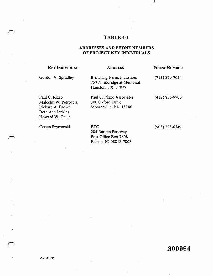
TABLE 4-1
ADDRESSES AND PHONE NUMBERSOF PROJECT KEY INDIVIDUALS
KEY INDIVIDUAL ADDRESS PHONE NUMBER
Gordon V. Spradley Browning-Ferns Industries (713)870-7054757 N. Eldridge at MemorialHouston, TX 77079
Paul C. Rizzo Paul C. Rizzo Associates (412) 856-9700Malcolm W. Petroccia 300 Oxford DriveRichard A. Brown Monroeville, PA 15146Beth Ann JenkinsHoward W. Gault
Ceress Szymanski ETC (908)225-6749284 Raritan ParkwayPost Office Box 7808Edison, NJ 08818-7808
300084r3-tl-76l/93
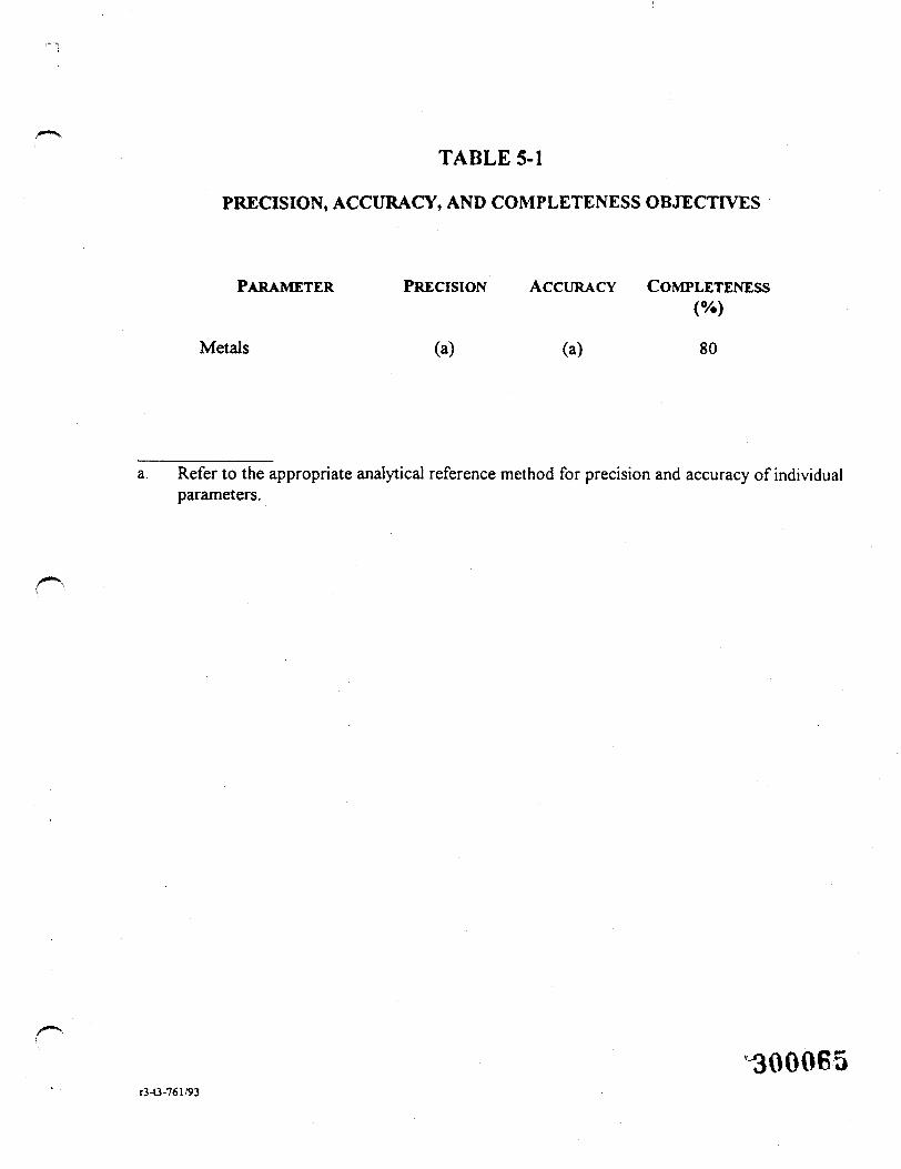
TABLE 5-1
PRECISION, ACCURACY, AND COMPLETENESS OBJECTIVES
PARAMETER PRECISION ACCURACY COMPLETENESS
Metals (a) (a) 80
a. Refer to the appropriate analytical reference method for precision and accuracy of individualparameters.
"300065r3-O-761/93
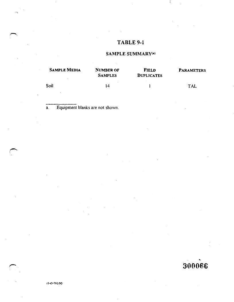
TABLE 9-1
SAMPLE SUMMARY<«)
SAMPLE MEDIA
Soil
NUMBER OFSAMPLES
14
FIELDDUPLICATES
l
PARAMETERS
TAL
a. Equipment blanks are not shown.
300066
r3-t5-761/93
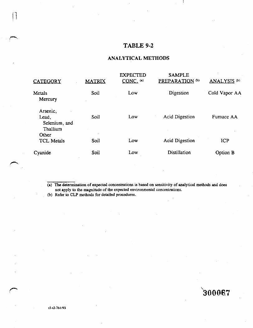
TABLE 9-2
ANALYTICAL METHODS
CATEGORY
MetalsMercury
Arsenic,Lead,
Selenium, andThallium
OtherTCL Metals
Cyanide
MATRIX
Soil
Soil
Soil
Soil
EXPECTEDCONC. (•>
Low
Low
Low
Low
SAMPLEPREPARATION *> ANALYSIS 0»
Digestion
Acid Digestion
Acid Digestion
Distillation
Cold Vapor AA
Furnace AA
ICP
Option B
(a) The determination of expected concentrations is based on sensitivity of analytical methods and doesnot apply to the magnitude of the expected environmental concentrations.
(b) Refer to CLP methods for detailed procedures.
300067r3-t2-761/93
o c x m w
300068

FIGURES
300089
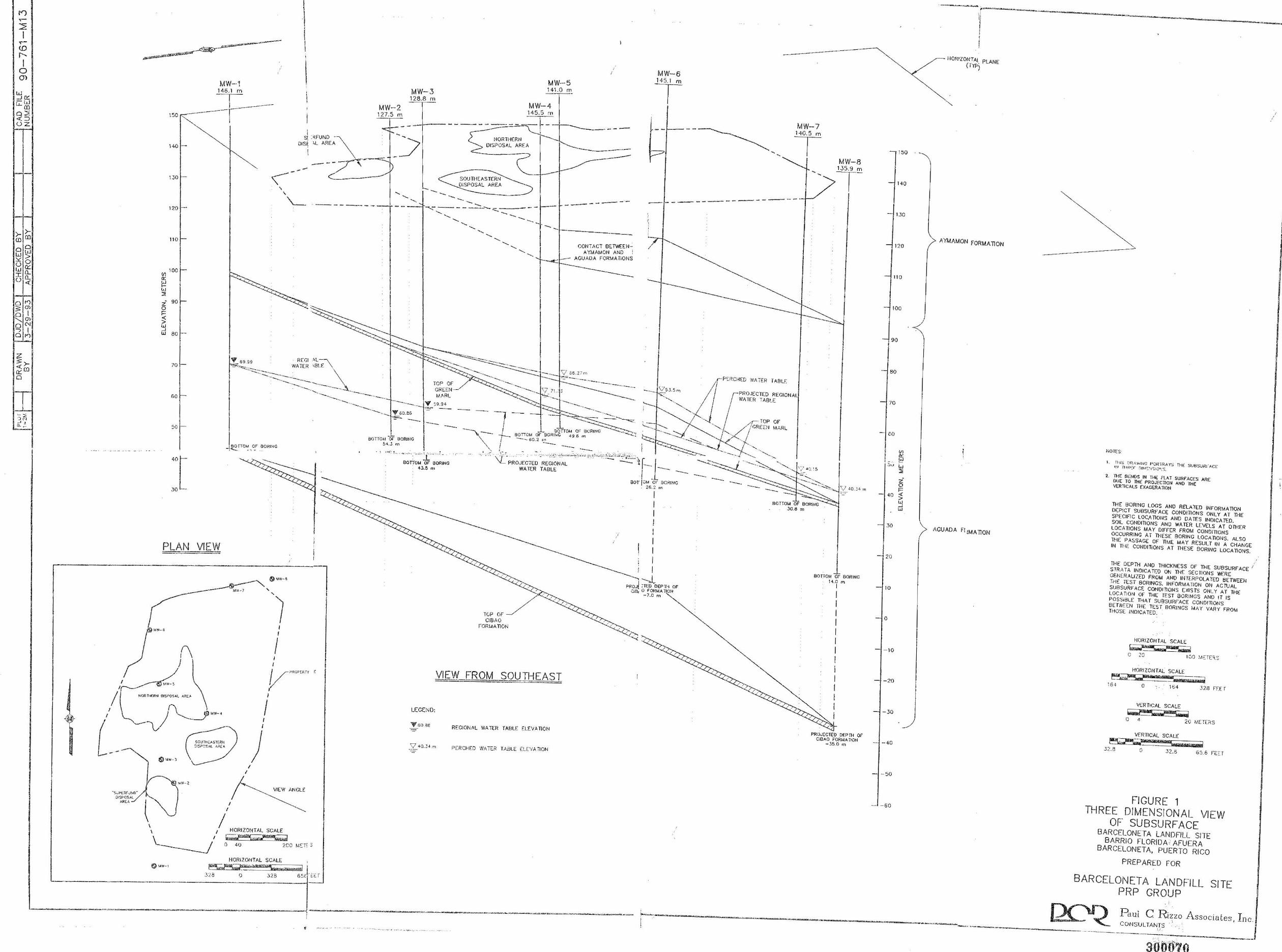
-·-·- -· f') ~
::2' I ~
(D
r--I
0 0)
w _J"" -w t,_ 0)
02 <(::) oz
·- --
>- >-CD ill
0 0 w ls;' "' 0 0 cc w (L I 0.. 0 <(
~ "' a, 0 I '-. a, 0 N -, I a "'
i >-<( (D
Cl'. 0
,--· ·- ,_ ' ' ·::i ti _, ii ~-
MW-·1 146,1 m
T ------150 --- --1
. •
\ I
\ '
I MW-3 128.8 m
MW-2 T 127. 5 m
MW-5 141.0 m
MW-4 14 5.5 m
---------
I
14-0 -s(:RFUND - \
DIS~ :..L AREA
1 1S1 NORTHERN DISP OSAL AREA
,-....._ ____ _ ---~
MW-7
T 130 <
' '
----r·C:~-___, SOUTHEASTERN
O!SPOSAL AREA
\___ ----- ------120
110
V'J 100
~ w :,
2• 90 0
" ;; w d ea
70
60
so -
40[ 30 •
PLAN
BO fTOM Of BORING -.........
VIEW
-------•,,r,.1-7 ' '
(\ J
; I I
I
' ''/
,'~· ••-' ,.OR 11-11:RN OISi>Q SAl. Al'f,\
'v) (\_____ _ _y, ""·.
1 l scum~"" --ea-,--.._
- -·
· s;;l'L~FJHO" :l15l'OS.>L
~HCA
6) .;m-l
,,..,, •• 2
;l:;;>'.!'>Al >..~EA
, ,
I I
) VIEW AN GLE
(' ,'
\ I HORI ZONTAL SCALE \ f -- ,-,,,,t;rr..---:-:-~
I r-~""--~ ~ \_______; O 40 2CO M~Ti ~
HORIZONTAL SCALE
-------- ·- --1--------~
CONTACT BETWEEN -A YMAMON AND i
AGUADA FORMATIONS
~--:-~---. . -~--... - -- . V os. 2 7m
TOP OF GRErn MARL
···-- ··-... ~ V 59_-:i.:. _,,,,__ -~ °"".::::...-:::.:·-·- ---- ·-···- \75.3_5 ,,.,
··-........ '-
BOTTGM OF SORING 5 4 . .3 m
. ' "'" '·-- '"-··: '·" -~ "" -~ - .. BOTTOM OF 8 0RING
U.5 rt1
TCP OF CIB AO
FORMATION
VIEW FROM SOUTHEAST
LEGEN D:
"fl 6fJ .B6 REGI ONAL WATER TABLE ELEVATION
V 40.34 m PER CHED WATER TABLE E!...E 'IATIO~I
;--
I I I I I I I I I
--...., -J, PROJ( :TEO OEP TI-1 OF
Ci8, 0 l'Of<MA "TION -7.o m
~~;.;;;;;;.i • . "3'.! B ; - · 3 28 65f !: i:: T
.. ,
------
' '
P'c:RCHED WATER TA8LF.
P~O.JECTE:D REGIONA WAT[R TABLE
' '
'/ 40,15
MW-B 135.9 m --r-
BOTTOM OF' BORING Jo.am
80TTOM OF SORING · 1~.o m
I
I I I I I I I I I I I I I I
PROJECTED DEP rH OF CIBAO FORMA T!ON
- 35.0 m
L_, ____________ , _ _ _
'--,.·- -------·---· ----" .. .•. ---·---• i
150
140
lJO
120
11 0
100
90
• 80
70
- cO
z 0 ,=
- 4 0 ~
ci 30
20
10
0
- 10
-20
-30
- --40
- 50
~ - 60
I-IORIZONTA! PLANE" { TYP)
·-..._
Jl.YMAMON FORMATION
AGUADA fl !MA TION
NOTES·
2. ·o;E S!:'.NOS IN THE FLAT SURF' ACES ARE our TO THE PROJECTION ANO lHE VERTICALS EXAG£RA TlON
THE BOR!NG LOGS ANO RELA TEO INFORMATION DEPICT SUBSURFACE COND!TI ONS ONLY AT TI➔E SPECIFIC LOCATIONS ANO DA TES INOICA TEO. SOIL CONDITIONS ANO WATER LEVELS AT OTHER LOCATION S MAY DIFFER FROM CONDmoNs OCCURRING AT TH ESE BORING LOCATIONS. ALSO THE PASSAGE OF T!ME MAY RESULT IN A CHANGE IN TTIE CONDITJONS AT THESE 90RWC lOCA"OONS.
THE DEPTH ANO THICKNESS OF THE SUBSURFACE 1 STRATA INDICATED ON THE SEC TIONS WERE GEN ERALIZED FROM AND IN TERP OLA TED BETWEEN rr1E TEST 80RINGS. INFORMATION ON ACfuAL SUB SURFACE COMOITlONS EXISTS ON LY AT THE LOCATI ON OF THE TEST SORINCS ANO IT IS POSSIBLE TI-IA T SUBSURFACE CONDITIONS BETWE EN THE TEST .BORINGS MA Y VARY FROM THOSE INDICATED . .
HORI ZONTAL SCALE c:=-------7 ----=-=-C 2G 100 ),IC:TERS
HORI ZONTAi: SCAI.E
~,.&~w~ 164 0 ' 164 328 Ff:Ef
VERTICAL SCALE
~ 0 4 20 METE~ S
3 2.8
VERTICAL SCALE lilbl"-----"ff>1'1;,g;jll,\lH,;,;.ewo ~, L-~--lililMI--· -«wvenrz ,-
0 32.5 65.6 ~-E ::T
FIGURE 1 THREE DIMENSIONAL VIEW
OF SUBSURFACE BARCELONETA LANDFILL SITE
BARRIO FLORIDA AFUERA BARCELONETA, PUERTO RICO
PREPARED FOR
BARCELONETA LANDFILL SITE PRP GROUP
P aul C Rizzo A ssocia tes , Inc CONSU LTAN_T,S
--· ··-·--·---··~~--------·-----·--
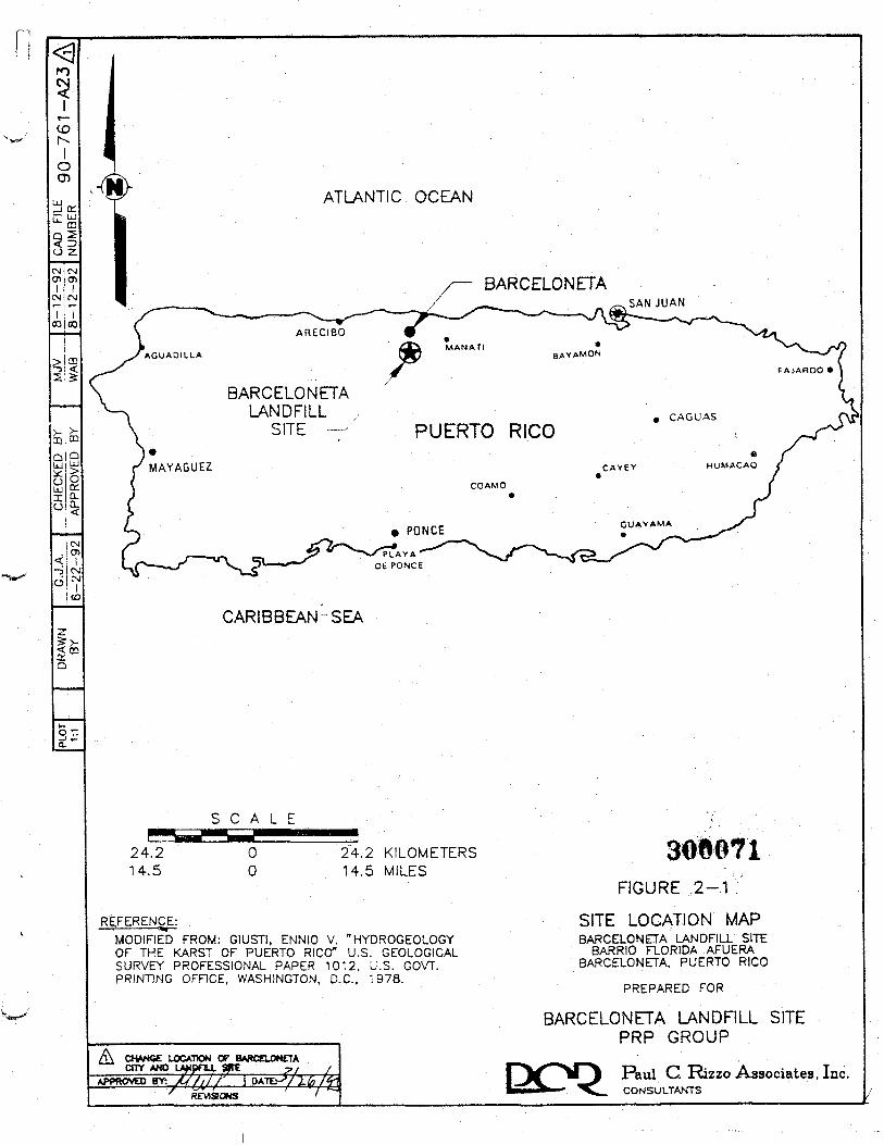
3!to
<rtn
JitMO>I
CNltMr-
co | co
>icn6 <
>
Q T-J »-Q.
ATLANTIC OCEAN
/— BARCELONETA/ ^ „ SAN JUAN
BARCELONETALANDFILL
SITE PUERTO RICO
CARIBBEAN SEA
24.214.5
S C A L Emf00
"24:2 KILOMETERS14.5 MILES
REFERENCE;MODIFIED" FROM: GIUSTI. ENNIO v. "HYDROGEOLOGYOF THE KARST OF PUERTO RICO" U.S. GEOLOGICALSURVEY PROFESSIONAL PAPER 1012, U.S. GOVT.PRINTING OFFICE, WASHINGTON, D.C., '978.
CHANGE LOCATION OF BM*CE1ON£TACITY AND
APPROVED BtY; X///// I OATE.^/2.^2/, .
7
FIGURE 2-1
SITE LOCATION MAPBARCELONETA LANDFILL SITE
BARRIO FLORIDA AFUERABARCELONETA, PUERTO RICO
PREPARED FOR
BARCELONETA LANDFILL SITEPRP GROUP
Rml C. Rizzo Associates, Inc.CONSULTANTS
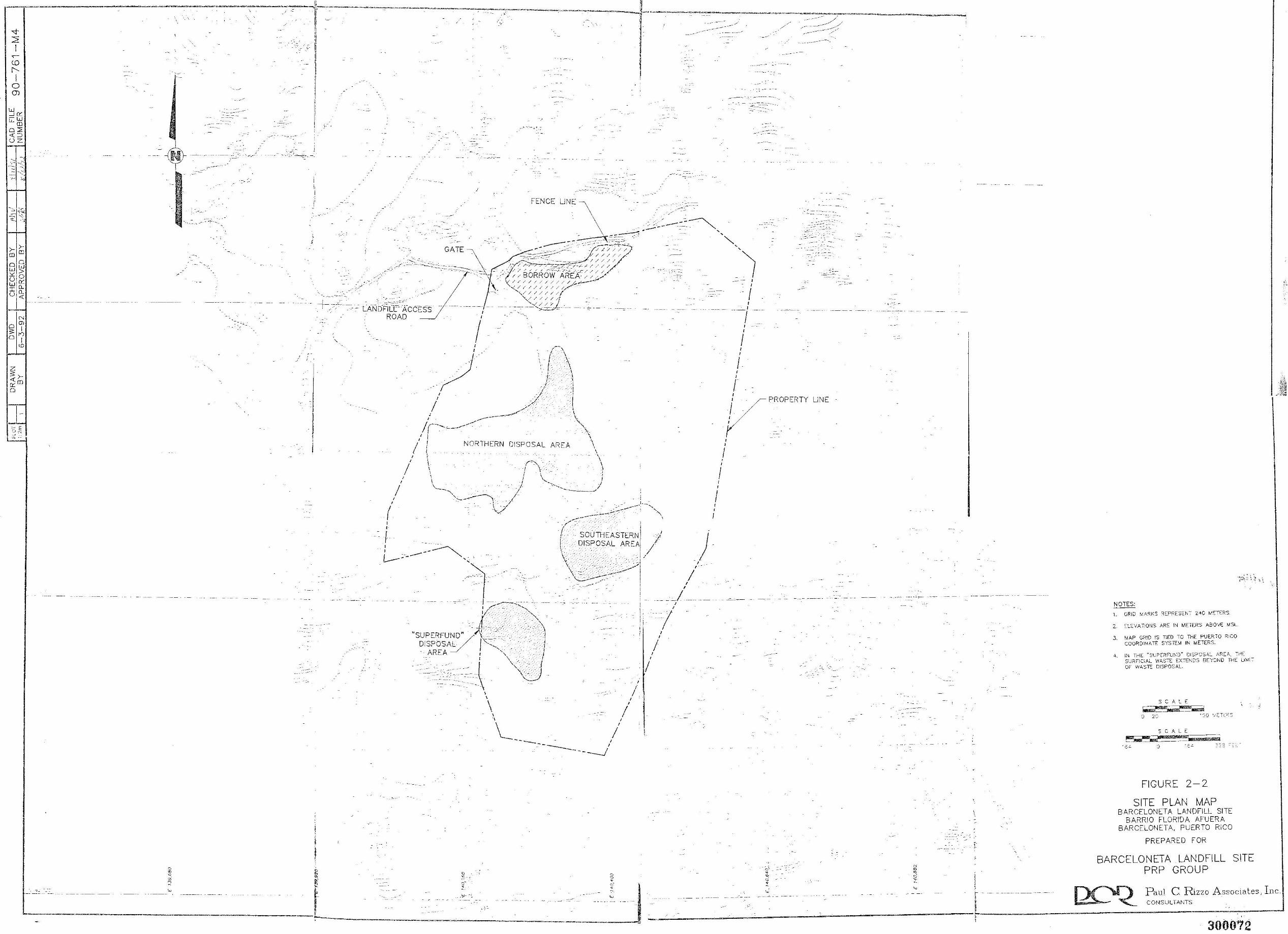
~
<D r---1
0 Ol
>- >(D (D
0 8w "' > uO w "' - [L ~ [L u<
N
0 m
3 I n 0 I
"'
z 3 >-< (D [l'. 0
7: '3 E -• N ·-~ ·-
.,_ -
'---------
- --~---
I
·------:.
--+-. _;,_'
'
----
LANDFiLC ACCESS .. , , . ROAD
, , I
I , ,
/ ,.--_, , I
-- r- \ I \
.r -\ ,-•- -, ,_· :1 .,/ . .-1
. ' __ -/·-· .I . ,,.:-;-·. l
,,,-.,-'" l - \ ---- . . \_ Ir-,~----- '" I I "..;
I ,
I I \
!, 1 NORTHERN DISPOSAL AREA ,
I , . I : \ \
I \. f~ ' I I \ 1
I \ ! \ :1 I \ I "-. I
I \__ J_ k~, .)
·, i '·---~--~' I '-....-~ - /
I , \ /.
( \ . _,-·\/
i SOUTHEASTERN' / DISPOSAL AREAi //
1
-·--.
.. _/
,
I
~ Q !>) '.C ~
g i
···7• ....
I ' ,
' '
' ' I
' '
I ' I
)
' , I , ' I ,
' r ,
-_::-:.
VPROPERTY
, ' I
-----'-·-
LINE
- - --~ ··-- .c,_.
NOTES:
,.
2. C:LEVAT!ONS AR!:: IN METERS ABOVE MSL.
3. MAP GRID !S TIED TO THE PUERTO RICO COOROINA TE SYSTEM IN METERS.
4. IN TrlE "SUPEiFUt✓ D" OIS?CSAL ARC:A, 'HE su,;;:FIC.AL WAS7E EXTE~<DS BE'(OND THE UM!OF WAST:: DISPOSAL
SCA'~E
~~~ '.) r- ·::,o vc:1c:c=s
S C A L E -'.)
FIGURE 2-2
SITE PLAN MAP BARCELONETA LANDFILL SITE
BARRIO FLORIDA AFUERA BARCELONETA, PUERTO RICO
PREPARED FOR
BARCELONETA LANDFILL SITE PRP GROUP
Paul C. Rizzo Associates, Inc. CONSULTANTS ______ t_~ ______________ : _ ! --· ... I ________ _] r _; ______________ _;. ______________ , __________________________ __,
' 300072
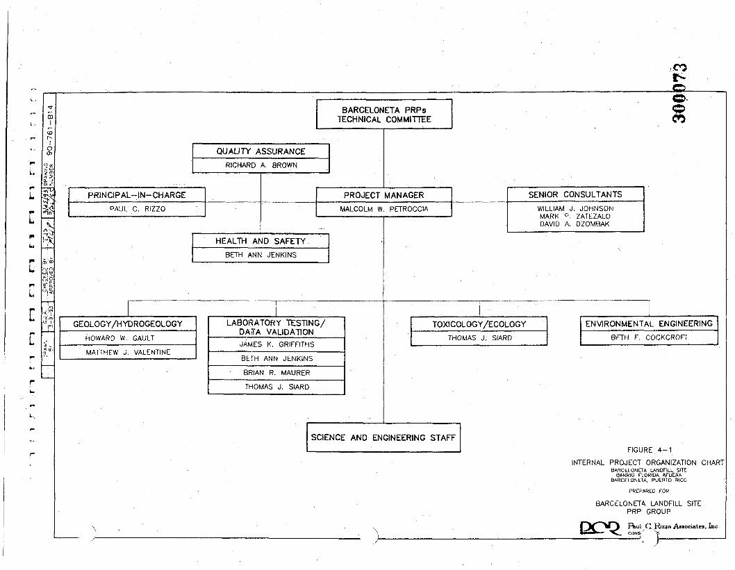
[
c
BARCELONETA PRPsTECHNICAL COMMITTEE
QUALITY ASSURANCERICHARD A. BROWN
PRINCIPAL-IN-CHARGEPAUL C. RIZZO
03r-JCL.
C*5
PROJECT MANAGERMALCOLM W. PETROCCIA
HEALTH AND SAFETYBETH ANN JENKINS
GEOLOGY/HYDROGEOLOGY
HOWARD W. GAULT
MATTHEW J. VALENTINE
LABORATORY TESTING/DATA VALIDATION
K.
BETH ANN JENKINS
BRIAN R. MAURER
THOMAS J. SIARD
SENIOR CONSULTANTSWILLIAM J. JOHNSONMARK P. ZATEZALODAVID A. DZOMBAK
TOXICOLOGY/ECOLOGYTHOMAS J. SIARD
ENVIRONMENTAL ENGINEERINGBETH F. COCKCROFT
SCIENCE AND ENGINEERING STAFF4-1
INTERNAL PROJECT ORGANIZATION CHARTBARCELONETA LANDFILL SITE
BARRIO FLORIDA AFUERABARCELONETA, PUERTO RICO
PREPARED FOR
BARCELONETA LANDFILL SITEPRP GROUP
F*1"1 C RizzoAssociites.Inc.CONS' "
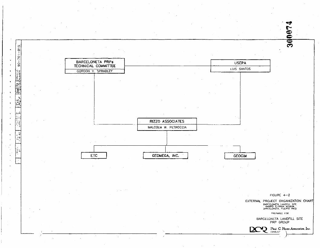
ocrm
I(Dr~>I
OCTl
"•?Ss
BARCELONETA PRPsTECHNICAL COMMITTEE
GORDON V. SPRAOLEY
USEPALUIS SANTOS
RIZZO ASSOCIATESMALCOLM W. PETROCCIA
ETC GEOMEGA, INC. GEOCIM
FIGURE 4-2
EXTERNAL PROJECT ORGANIZATION CHARTBARCELONETA LANDFILL SITE
BARRIO FLORIDA AFUERASARCELONETA. PUERTO RICO
PREPARED TOR
BARCELONETA LANDFILL SITEPRP GROUP
jRiul C Rizzo Associates. Inc.COr4SULf \
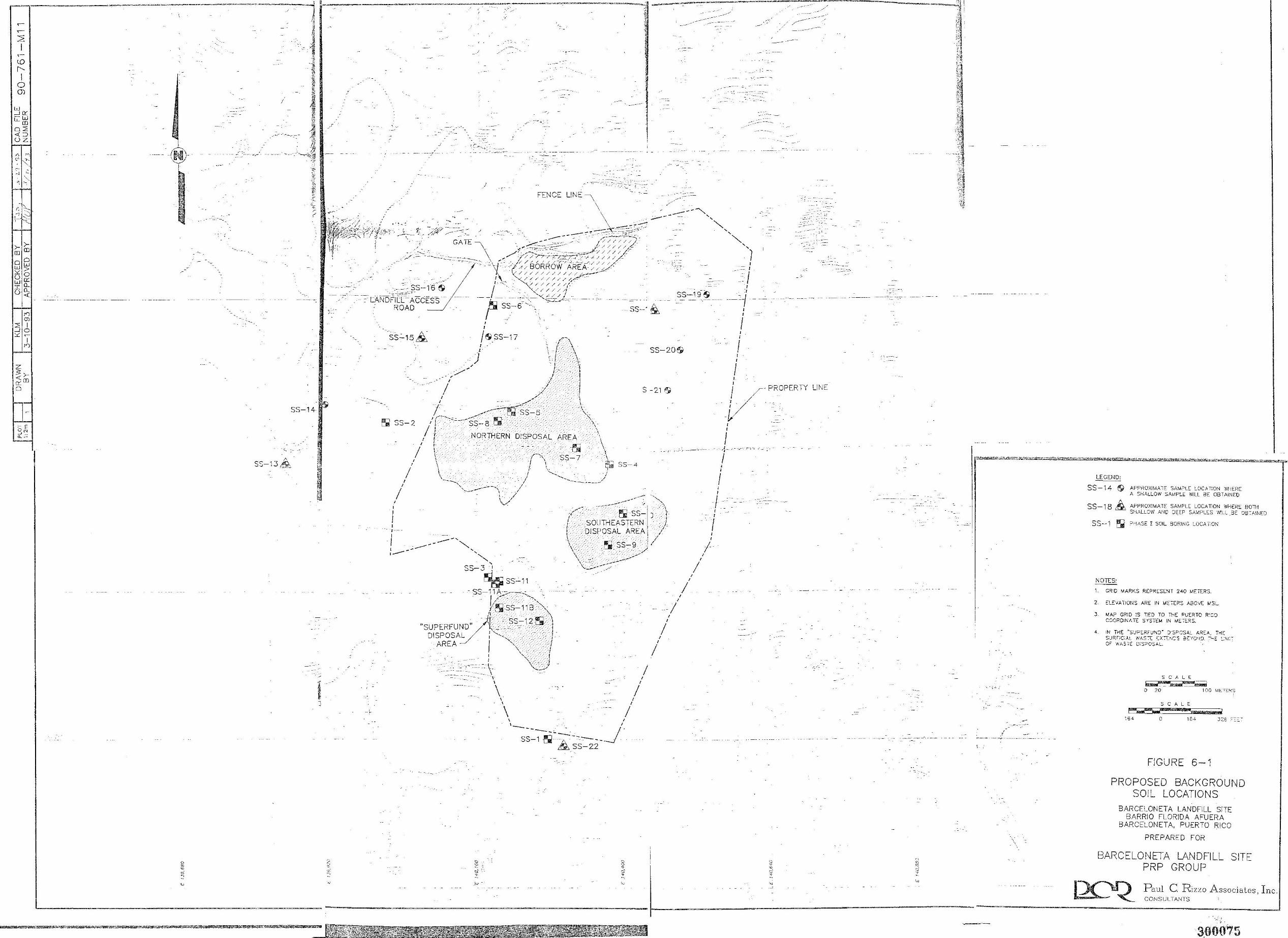
-···-·------·-·-----------------j
2 I ~
co l'--1
0 CJ)
w --' [l' -w LL (D
o::e ""'::::, uz
"" "" C-'- ~h .
>- >(D (D
00 WW " > uO w [l'. T Q. - u. u ""'
l •l
;j -3:
. - --·
- - -- _.·-,.
!
SS-13,&
~-~-,~--~~-~~---~--~~=---=--,.·: • :- • J
-· ' ,-
w J;~f: ti/" . :~. \-r
'.3S-l6 51 "----C=·_.:;:.--
LANDFILL~ ACCESS ROAD
"•
.---.
) ·c'.--·_·-·
FENCE
--
ss-·&
' ' / 51. SS-17 ,--,
SS-19~
' ' . I ' '
- -{
' ' I ' '
--_-__ ,·
)_1 f_:< \\ SS-20!',i I
l -·'.·
[' '.'_\'
/ . • ,/ i--· ··"'i -- r:--, _I , -_ -t
! _;· -1
I ;t -I / J
I /" ~ S -21 5,
~ SS-2
I '
' '
I I
'
I - - --- -· 0<~ .· - \ I ~---~:~ss--s · ~\-_
I,--",::,- ----· -.·_. !(7.· _.'\. .. 1) -- SS--8LS-- -.\
I } NORTHERN D!SPOSAL ARE.A. \_
: ~ \ \.- , . .Ell 'i 1 r·,< ·ss- 7 ·, \ ·f \ tfuJ' \ I ',. lj
I "--.... j \ / -----.... /
---.._, I -·-----
'~ ---------, / ---- \ // ' , •'·
SS-4
··-,.---, ' . .,.,.<· ---\_
., l's ss- J '
' ,----/ .SOUTHEASTERN -/ t - DISPOSAL AREA /
/ ------........ -\_. ' _-, ' ,: /
\.·.:-':/ ._.5r ~S-:-_9 ) / l -- ' I-- '"-._ ~-- . . . .,.
\:.. -----~-;;_,;>-' SS-3 1 - •
~SS-11 - SS-11 A -/----c
--· k;Iiss-~ 11~',,~\ /[ ... '\ 'l ss-12~·-:-.\
"SUPERFUNV" ' - -- . : DISPOSAL I' ... ._,-. /.
AREA I "",, --·>/ \· _-,
' ' \ ' ' \
' ' \
',\_ -.·_- .:J ,._:__,;,,
\, _ __....,.
' ' 1__ / ss~~~-:... ______ _j.
&ss-zz
I I ' '
I ' '
' ' I I
' ' I
, , I
' ' I
' '
' ' I ' ' V PROPERTY LINE
' ' I ' ,,--
I
I ' ' I
' ' I ' ' /
.-,-~ ------ _, -~- ..
I I --'="'' ,,. r.·•wc.-·s c""'~~·•,·•·R¼C~~m,rn,;,,;,cs,•a ~, "-•=-•~~~£,'""'"''"~i
LEGEND:
SS-14 &} APPROXIMATE SAM~LE LOCAT:ON WiiERE A SHALLOW SAMPLE WILL BE OBT AiNEO
SS-18 £ APPROXIMATE SAMPLE LOCATION WriERE BOTH SHALLOW AMD J:CEF S,\),1PL!::S W~LL _BE 08:"A!NED
SS-1 ~ ."'HASE I SOil BORING LOCA TiON
NOTES:
1. GRID MARKS REPRESENT 240 METERS.
2. ELEVALIOt-lS ARE IN ME;-rns ABCVE ~SL
3. MAP GRID :S T)ED TO THE PUERTO R'CO C'JQROIN/, TI: S f$7IM IN M[":':::.'<S.
4. IN TrlE ~S'JP[."IFUNJ. :rs~-'.JSAL AREA, THE S0JRFiCAL WA.s::: ~;.::,:~cs 3;::·,o•<'.l -..,,: L:\.cOF WASTE D:S?OSAL.
S C A L € ~·--, ~··---~ 0 ,o 1 00 Mf-~TC:f<S
S C A L E
~.;;;;;.;;;.;;.;, 154 0 1 64 32t " - -
FIGURE 6-1
PROPOSED BACKGROUND SOIL LOCATIONS
BARCELONETA LANDFILL SITE BARRIO FLORIDA AFUERA
BARCELONETA, PUERTO RICO
PREPARED FOR
BARCELONETA LANDFILL SITE PPP GROUP
Paul C. Rizzo Associates, Inc. CONSULTANTS
·----------------------------------------
300075
APPENDIX A
CO
APPENDIX A
ETC LABORATORY QUALITY ASSURANCE PLAN
300077
r2-ban-761/93
ETC Con. ETC/Edboa Quality A*gar»ncc PUa Doc QAQ00418LEDDate: 10/12/92
Section 14)Revision 3
Page 1 of 2
LABORATORY QUALITY ASSURANCE PLAN
Environmental Testing and Certification Corp.234 Raritan Center Parkway, P.O. Box 7808
Edison, New Jersey 08818-7808(908) 225-6700
Approval
or Quality Assurance
No.
300078This document has been prepared by ETC Corp. for the ETC/Edisoo facility. The material contained herein is not to be disclosed to,or made available to any person or person* without prior written approval by authorized ETC Corp. personoeL
ETC Corp. ETC/Edlson Quality Assurance Pl«n Doc. QAQ00418JEDDate: 10/L2/92
Section 1.0Revision 3
Page 2 of 2
FOREWORD
Environmental Testing and Certification Corp. (ETC Corp.) has provided high quality analyticaland data management services to major industrial corporations, waste disposal firms andgovernmental agencies since 1981. The laboratory's specialized services are directed at theaccurate measurement of contaminants in water, soils and sediments, and hazardous wastes. ETCCorp.'s services have been developed in direct response to regulations written and enforced byfederal and state environmental agencies. The laboratory has historically performed specialproject investigations that have enhanced the organization's competence and versatility in the fieldof analytical chemistry.
ETC Corp. is a wholly owned subsidiary of Applied Bioscience International, Inc. (APBI), EastMillstone, New Jersey. The ETC Corp. analytical laboratory includes two facilities: ETC/Edisonin Edison, New Jersey and ETC/Santa Rosa in Santa Rosa, California. A recent July, 1992acquisition of National Express Laboratories, Inc. (NatEx) by APBI has created a combinedETC/NatEx network with extensive environmental analytical capability and expertise. TheETC/NatEx analytical laboratories include facilities in the States of New Jersey, California,Louisiana and Washington. This written quality assurance plan documents the procedures usedto manage custody elements and analytical processes at the ETC/Edison facility, which isgenerically referenced throughout the text as ETC.
This Quality Assurance Plan has been prepared to conform in content with the USEPA QAMS-005/80, 'Interim Guidelines and Specifications for Preparing Quality Assurance Project Plans",December 29, 1980. QAMS-005/80 includes a section titled "Project Description". In thisdocument, the laboratory policy statement replaces specific project description information. Thetables and figures referenced throughout the document are found in the appendix. The appendicesof project specific quality assurance documents may include additional elements or information.
This document describes ongoing laboratory operations for routine analyses performed at ETC.As such, the material contained within is subject to change. Changes may be based on specificproject requirements or procedural system modifications geared towards operational process andquality improvements. This document is reviewed and updated on a minimum yearly basis.
Because of the variability of samples and matrices, it is not unusual to find that the performancecriteria of a particular method is unachievable on particular samples. In such circumstances, anymethod or criteria modification will be noted in each final report.
300079
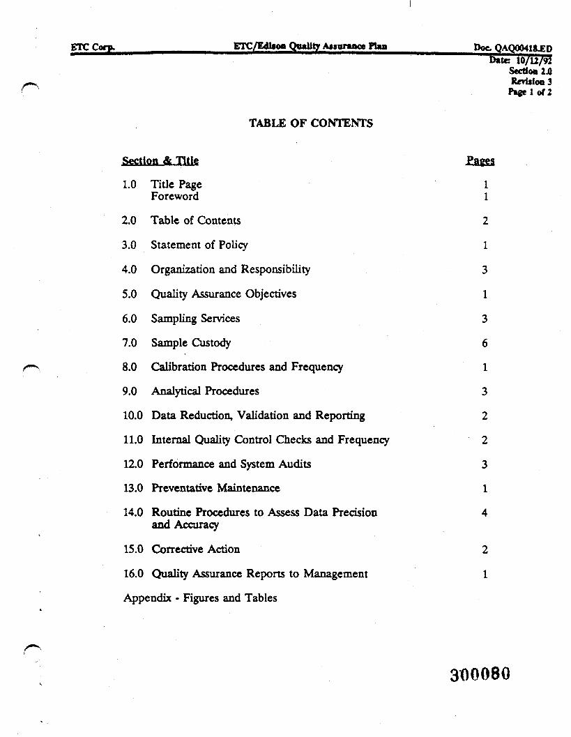
ETC Corp. ETC/EdltoB Quality Anunmce Plan Doc. QACXXMl&ED
TABLE OF CONTENTS
Section & Title
I.0 Title PageForeword
2.0 Table of Contents
3.0 Statement of Policy
4.0 Organization and Responsibility
5.0 Quality Assurance Objectives
6.0 Sampling Services
7.0 Sample Custody
8.0 Calibration Procedures and Frequency
9.0 Analytical Procedures
10.0 Data Reduction, Validation and Reporting
II.0 Internal Quality Control Checks and Frequency
12.0 Performance and System Audits
13.0 Preventative Maintenance
14.0 Routine Procedures to Assess Data Precisionand Accuracy
15.0 Corrective Action
16.0 Quality Assurance Reports to Management
Appendix - Figures and Tables
Date 10/U/92Section 2.0Revision 3
Pagel of2
Pages
11
2
1
3
1
3
6
1
3
2
2
3
1
4
2
1
300080
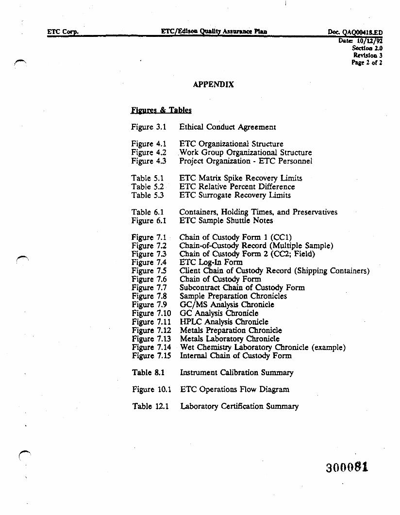
ETC Corp. ETC/Edisoo Quality AMarance Plan Doc. QAQOMl&ZDDate 10/12/92
Section 2.0Revision 3Page 2 of 2
APPENDIX
Figures & Tables
Figure 3.1 Ethical Conduct Agreement
Figure 4.1 ETC Organizational StructureFigure 4.2 Work Group Organizational StructureFigure 4.3 Project Organization - ETC Personnel
Table 5.1 ETC Matrix Spike Recovery LimitsTable 5.2 ETC Relative Percent DifferenceTable 53 ETC Surrogate Recovery Limits
Table 6.1 Containers, Holding Times, and PreservativesFigure 6.1 ETC Sample Shuttle Notes
Figure 7.1 Chain of Custody Form 1 (CC1)Figure 7.2 Chain-of-Custody Record (Multiple Sample)Figure 73 Chain of Custody Form 2 (CC2; Field)Figure 7.4 ETC Log-In FormFigure 7.5 Client Chain of Custody Record (Shipping Containers)Figure 7.6 Chain of Custody FormFigure 7.7 Subcontract Chain of Custody FormFigure 7.8 Sample Preparation ChroniclesFigure 7.9 GC/MS Analysis ChronicleFigure 7.10 GC Analysis ChronicleFigure 7.11 HPLC Analysis ChronicleFigure 7.12 Metals Preparation ChronicleFigure 7.13 Metals Laboratory ChronicleFigure 7.14 Wet Chemistry Laboratory Chronicle (example)Figure 7.15 Internal Chain of Custody Form
Table 8.1 Instrument Calibration Summary
Figure 10.1 ETC Operations Flow Diagram
Table 12.1 Laboratory Certification Summary
300081
ETC Corp. ETC/Edlsoo Quality AMBTMM* PUa Doc.DmtK 10/12/92
Section 3.0Revision 3
Page 1 of 1
STATEMENT OF POLICY
Environmental Testing and Certification Corp. is committed to meeting the quality standards ofthe regulatory environmental laboratory industry and the regulated community. ETC Corp.'sobjective is to consistently produce analytical data which is of known quality and meets the qualityobjectives of the methods and the data user. This will enable the data user to make rational,confident, cost effective decisions on the assessment and resolution of environmental problems.
Laboratory Ethics
ETC has a written ethical code that all employees are expected to adhere to. The code describesthe high scientific and personal standards necessary to ethically conduct business in the industry.ETC policy requires that all employees sign an ethical conduct agreement (Figure 3.1), bindingthem to the principals of the code. The laboratory's Code of Ethics is presented below.
ETC Corp. provides analytical chemistry services on environmental matters to the regulatedcommunity. The data the company produces provides the foundation for determining therisk presented by a chemical pollutant to human health and the environment. Theenvironmental laboratory business is dependent upon the accurate portrayal ofenvironmental chemistry data. The process is reliant upon a high level of scientific andpersonal ethics. Accordingly, ETC has adapted the following ethical code which eachemployee is expected to adhere to:
o To search for scientific truths by use of the scientific method.
o To be faithful and incorruptible, respecting confidence, advising honesty.
o To maintain professional integrity as an individual.
o To place the public welfare above any considerations of self-interestrecognizing and responding to community concerns.
o To present services in a confidential, honest, and forthright manner,
o To produce results that are accurate and defensible.
o To comply with all pertinent federal, state and local laws and regulations asit relates to his or her practice.
o To provide employees with guidelines and an understanding of the ethical andquality standards required to work in this industry.
300082
ETC Corp. ETC/EdUott Quality Amirmnce PUa Doc. QAQ00418.ED, - Date: 10/l1755
Sectioo4J)Revision 3
^ Page 1 of 3
ORGANIZATION AND RESPONSIBILITY
The ETC organization (Figure 4.1) is designed around its clients' specialized needs. The structureallows close, coordinated interactions and promotes the common goals of successful projectmanagement and quality data. ETC's quality assurance group is independent of laboratoryoperations. The ETC laboratory operations is segmented into three distinct work groups thatmanage specific analytical product lines. The functional organization of the work group ispresented in Figure 4.2. A separate wet chemistry group performs all conventionals chemistrytesting.
Project Organization
Projects at ETC are monitored by project teams selected prior to project initiation. The teamsconsist of representatives from laboratory operations, quality assurance, and marketing. The goalis to set up and monitor the project to meet client needs. The analytical product (for example,CLP or RCRA) determines the work group which is assigned to manage the operations. Figure4.3 presents the key individuals on the ETC project team.
Kev Individual Responsibilities
The minimum responsibilities for key project personnel are as follows:
Account Executive:
o Supports client regulatory programs.
o Coordinates pre-project meetings.
o Establishes contractual terms and conditions.
o Provides oversite of the project
Technical Proct
o Serves as primary client contact for the project.
o Provides advisory consultation to clients on regulatory and technical issues.
o Attends pre-project and project progress meetings; assists in client or project audits.
o Defines project scope through detailed documentation of client and project quality andtechnical requirements.
/""""N' o Communicates the client and project quality and technical requirements to laboratory
personnel; implements the project. ^ _ _300083
ETC Corp. ETC/Edlaoo Quality Asaunmct PUn Doc QAQ00418JED~~~' Date lO/li/92
Section 4.0Revision 3
Page 2 of 3
o Coordinates field activities with sample management personnel to ensure proper delivery ofshipping containers, sample bottles, etc.
o Tracks and manages the project through the laboratory.
o Updates the client on nonconformances and responds to requests for information.
o Coordinates technical report generation to ensure client commitments are achieved.
Work Group Manager:
o Provides supervision of entire work group operations.
o Implements the laboratory quality assurance plan.
o Ensures proper scheduling and execution of testing programs.
o Assures that quality assurance and quality control criteria of analytical methods and projectsare satisfied.
o Assesses data quality and takes corrective action when necesasary.
o Notifies the project team of specific laboratory nonconformances and changes.
o Approves and releases technical and data management reports.
o Ensures that sample custody is maintained at the laboratory.
o Approves project specific laboratory quality assurance plans.
Assurance Officer:
o Serves as the official organizational contact for quality assurance matters. Concerns mayinclude, but are not limited to, quality assurance plans, standard operating procedures,analytical methodologies and protocols, audits, certifications, support services, and correctiveactions.
o Identifies and responds to quality assurance needs, assists in problem resolution and answersrequests for guidance, information or assistance.
o Provides guidance in the development of quality assurance plans.
o Reviews, evaluates and approves written quality assurance plans.
o Tracks the progress of quality assurance tasks (from preplanning to data assessment) andconsults periodically with project managers. 300084
ETC Corp. ETC/Edlson Quality Anunmcc PUa Doe. QAQ00418XDDate 10/12/92
Section 4JORevision 3
Page3oT3
o Monitors quality assurance/quality control functions and corrective actions throughout thelaboratory facility.
o Provides the General Manager reports of laboratory performance.
Analyst and Technician Responsibilities
Each individual in the ETC organization is responsible for their product or the service theyperform. Analysts and technicians who handle samples or analytical data have the followingminimum responsibilities:
o Performs the expected services and methodologies.
o Performs the quality requirements of their tasks.
o Takes any necessary corrective actions described in the analytical methods or protocols.
o Accurately communicates any sample or quality problems to responsible managementpersonnel.
o Adheres to the ETC Code of Ethics.
300085
ETC Corp. ETC/Edboo Quality Ajiormncc PUn ppc. QA<XH18.ED
'
Section 5.0RevUlon 3
of 1
QUALITY ASSURANCE OBJECTIVES
The quality assurance objectives of the laboratory must be consistent with specifications foranalytical services cited for projects and samples. The laboratory will perform analytical servicesand support in accordance with project requirements as specified by the client.
The data quality objectives of the laboratory are to produce complete, valid, and verifiable data.ETC's objectives are to execute the required methodologies and procedures, and to generateprecise and accurate measurements. Tables 5.1, 5.2 and 5.3 identify the laboratory's routinequality control objectives.
300086
ETC Corp. ETC/Edl*oo Quality Assurance PUa Doc. QAQ00418JEDDate: 10/12/92
Section 6.0Revision 3
Page 1 of 3
SAMPLING SERVICES
Field Support
ETC provides shipping containers (ETC Sample Shuttle™), custody documents, custody seals,sample bottles, labels, chemical preservatives for water samples, "blue ice" packs to maintainthermal preservation, and trip and field blanks to support field sampling events. Table 6.1 listssample container types, preservatives and holding times. ETC can provide shuttle pick up anddelivery services to its clients.
Upon receipt of the field samples at the laboratory, ETC ensures that sample bottles aremaintained according to preservation requirements and that sample storage conditions do notcontribute to the presence of test analytes in the samples.
Sample Shuttles • ETC Shipping Containers
The ETC Sample Shuttle™ was developed in 1981 by ETC staff for the transport of environmentalsamples from the field to the laboratory. The Sample Shuttle is a rugged carrying case lined withinsulating polyurethane. Insulating sleeves with pre-fonned slots hold the sample bottles. Thecontainer is lockable from the outside. Chain-of-custody seals and forms, employed for eachShuttle packed at ETC, ensure complete documentation and provide evidence of unbroken custodyof the Shuttle contents. The Shuttle meets or exceeds all protocol requirements (i.e., DOT,USEPA, ASTM) for shipping.
Figure 6.1 lists instructions for Sample Shuttle use and sampling notes. The Shuttle is configuredat the laboratory to provide the client with all of the sample containers needed for the analyses.
Preservation
ETC provides the necessary chemical preservatives and "blue ice" packs (at pre-frozen or ambienttemperatures, as per the client's needs) in the Sample Shuttles during the Shuttle packing process.High quality reagent grade chemical preservatives are used. It is the responsibility of thosecollecting the samples to properly use these materials and ensure that proper preservationtechniques are performed and preservative requirements are met ETC recommends that allsample containers be chilled with ice after collection prior to shipment in the Sample Shuttles.
Upon receipt of samples at the laboratory, the temperature of each Shuttle is measured andrecorded on the chain of custody documents. Similarly, the pH of bottles to which chemicalpreservative was added is measured (with the exception of sample collected for volatile organiccompounds), and the check recorded. When deviations from the required chemical or thermalpreservation are noted, the Technical Project Manager is notified, and clients may becomeinvolved with determining a course of action to follow.
300087
ETC Corp. ETC/EdLtoo Quality Aasormnct PUm Doc. QAQ004HLEDbate: 10/L2/92
Section 6.0RevUion3
Pa«e2of3
Sample Bottles
ETC provides properly cleaned sample bottles in the Shuttles for sample collection. Thelaboratory's thorough glassware cleaning procedures are outlined below. Used sample bottles arenever reused by the laboratory.
ETC does not prepare solvent rinsed containers for sampling. Solvent rinsed bottles are purchasedas projects necessitate. The vendor-prepared bottles, for example, 125 ml wide mouth bottles forvolatile organics in sediment, are prepared by USEPA CLP protocol.
Laboratory cleaning and preparation procedures for commonly used bottles are as follows:
Bottle Caps:
o All bottle caps are Teflon lined _
o New bottle caps are rinsed with deionized water, allowed to air dry in racks, then placed onbottles.
Amber Glass Bottles (1 L. 500 ml. 250 ml'):
o Rinsed with de-ionized water.
o All bottles are baked at 200°C for 30 minutes prior to capping and use.
Clear Glass Vials (40 ml for volatile organics^:
o Teflon lined septa for caps are stored in containers prior to use.
o Bottles, caps and septas are rinsed with de-ionized water, then baked for one hour at 105°Cin an oven used specifically for this purpose.
o Hydrochloric acid preservative is added to each vial used for aqueous samples.
o Upon client request 20 mg of sodium thiosulfate is added to remove residual chlorine in thesample.
o The bottles are capped and stored in sealed, air-tight metal containers prior to use. Bags ofgranulated carbon are enclosed to adsorb any organic vapors present
Amber Glass Bottles (125 mD:
o Rinsed with de-ionized water and air dried.
o Bottles are baked at 200°C for 30 minutes prior to capping and use.t
^ _300088
_,
ETC Corp. ETC/Edkon Quality Aaaonmce PUn Doc. QAQ0041&JDUte: 10/12/92
Section 6.0Revision 3
Page 3 of 3
o Bottles are prepared and labelled according to analysis prior to Shuttle packing.
Plastic Bottles:
o Bottles and caps are rinsed with deionized water and allowed to air dry in rarks prior tocapping and use.
o Bottles used to collect sample for the analysis of metals are rinsed in nitric acic solution.
Coliform Bottles:
o All bottles used for the sampling and analysis of coliform are purchased sterilized. They arereceived sealed and autoclaved.
300089
• rETC Corp- ETC/Edixm Quality Ai«urmnct PUa Doc
Date 10/U/WSection 7.0Revision 3
/""̂ Page lof 6
SAMPLE CUSTODY
Areas of Concern
The Chain of Custody in the laboratory consists of two areas of concern:
o Receipt and Log-in of Samples; and
o Maintaining Internal Custody of samples transferred throughout the laboratory.
Samples are physical evidence and, as such, are handled at ETC according to certain proceduralsafeguards. For some types of legal proceedings, a showing to the court that the custodiallaboratory is a secure area may be all that is required for sample data to be admitted as evidence.In other cases, the court may require a detailed showing of the hand-to-hand changes of custodythat a sample has undergone. Federal and state agencies and private sector clients may alsorequire varying levels of custody documentation from the laboratory. ETC is equipped to providethe defined level of custody documentation necessary.
Maintaining Custody bv NEIC Definition/**s- Custody is maintained by USEPA National Enforcement Investigations Center (NEIC) definition
when:
o The sample is in the actual possession of the responsible person, or
o The sample is in the responsible person's view after being in their possession, or
o The sample is in the responsible person's possession and then they locked or sealed it up toprevent tampering, or
o The sample is in a secure area.
ETC Laboratory Procedures
To satisfy these custody provisions, the following standard operating procedures are employed:
o The ETC laboratory is maintained as a limited access, secured facility.
o The grounds and parking areas around the building are patrolled on a regular basis by a rovingpatrol supplied by the Raritan Industrial Center.
o A security guard is on duty inside the building from 5:00 pm to 8:00 am on Monday throughFriday, and around the clock on weekends and on holidays.
{ * 300090
rETC Corp. ETC/Ediaoa Quality Aasunmct PUa Doc
bate: 10/12/$2Section 7JO
_ Revision 3C " P»«e2of6
o Employee access to the building and selected security area (including walk-in refrigerators)within the building is controlled by a computerized card reader employee identification system.Access is on a need basis.
o Visitors must register upon entering the lobby of the facility, and must be accompanied by theirhost at all times while they are in the building.
o Receipt and log-in of samples is fully documented and is performed in a controlled area,
o Samples are stored in a secure area.
o Walk-in refrigerators, freezers, and other primary sample storage areas are kept locked at alltimes or when unattended, dependent upon the function of the unit.
o Only designated ETC personnel have access to the primary sample storage areas,
o Samples remain in secured sample storage until removed for sample preparation or analysis.
o The internal transfer of samples is controlled and documented.
^*N ETC Sample Custodians
The Work Group Manager is responsible for the procedures performed by the responsible ETCSample Custodians who:
o Receive, inspect and record the condition of samples and shipping containers,
o Sign appropriate documents shipped with the samples.
o Verify and record correctness of sample documentation (for example, chain of custody: sealis intact, chemical preservatives are added, etc.).
o Initiate transfer of samples to appropriate lab sections with proper documentation (forexample, loglink, special instruction sheets, laboratory identification numbers, etc.).
o Place samples into appropriate storage and secure areas,
o Control and monitor access and storage of samples.
Custody Using the ETC Sample Shuttle™ System
The ETC Sample Shuttle™ system establishes and maintains the integrity of contents from thetime that the Shuttle is packed and shipped from ETC through shipment, sampling, transport, and
x—N return to ETC via its enclosed paperwork and seal system (refer to Section 6.0). Observationsconcerning the condition of the samples received are recorded on the Chain of Custody Form 1
i 300091
ETC Corp. ETC/Edltoa Quality Ajiormct PUa Doc10/12/92
SectJoo 7.0Revl«lon 3
Page 3 of 6
for single samples or Chain-of-Custody Record for multiple samples (Figures 7.1 - 7.3) upon thearrival and opening of the Shuttle. The original custody form is signed by the Sample Custodian,documenting sample receipt by the laboratory.
The laboratory initiates the custody procedure and assigns ETC sample codes ("numbers") to theclient samples. The ETC sample codes are utilized during the laboratory shipping, receipt, andlog-in procedures. Associated with each unique ETC sample number are specific analyses anddescriptions of services to be performed by the laboratory for the sample.
o Each sample bottle is labelled with: the pre-assigned ETC sample number, the analysis type,the site location/facility code, and chemical preservative as applicable.
o The ETC sample code is used to track the sample pathway throughout the analytical process.
o The ETC sample number is recorded on the Chain of Custody and Log-In Forms.
Sample Receipt and Log-In
The ETC employee who accepts receipt of client samples upon arrival at the laboratory is adesignated Sample Custodian. The Sample Custodian examines both the shipping containers andthe Chain of Custody and shipping documents. The Work Group Manager is responsible for thereceipt and log-in operations. The custody seal and documents are examined for compliance. Anyand all noncompliances are documented and the client contacted.
The ETC Shuttle or other shipping container is opened, the temperature taken, and all samplecontainers checked against the accompanying paperwork. The pH of sample aliquots which havebeen chemically preserved, except those used in volatile organics analyses, are monitored. Theclient is contacted by telephone regarding any custody problems or problems with the conditionof the samples upon receipt at the laboratory. Receipt documentation is completed and the ETCSample Log-In Form (Figure 7.4) is initiated.
The Sample Log-In Form is an internal document designed to summarize all the relevantinformation concerning a sample's receipt and analytical requirements. It is circulated internallyand instructs the laboratory with regards to the receipt, and the required analyses and reportingof the sample. The Log-In Form reflects the information present in the laboratory computersystem for the sample.
An individual Log-In form summarizes information for the samples received together in a groupfrom one client at one time. The individual forms are sequentially numbered to reference eachparticular summary. The index number is referred to as the "Log-Link* number. Each bottlereceived is labeled with its log-link number in addition to its unique ETC sample number. TheSample Custodian combines the following sample information on the Log-In Form: receive date,matrix, sample volume, client sample identification, and the analytical requirements informationobtained from the sample orders, including ETC sample number, Analysis types (A-types), andTurnaround (T/A).
300092
Con. ___________ETC/Edboa QoaUty Ajiunnct PUa Doc. QAQ00418JEDr Date 10/11/92
Section 7.0RrviilooJ
The top section of the log-in form contains information pertaining to the entire group of samples.The date and time received is recorded. Should the samples arrive before all the necessaryinformation is received from the client regarding analysis, the clock will not start (days will notbe counted towards the sample turnaround) until the information is obtained; actual sampleholding time is independent and not affected by the delay. The client required turnaround isrecorded at the top of the page. This determines the report due date. The Sample Custodianrecords the shipper, the number of ETC sample shuttles received, the client, and the site orfacility. Presence or absence of an airbill, and the airbill number is recorded on the log-in form.
The lower section of the log-in form contains sample specific information. The samples are listedby ETC sample number. Client sample identification, a brief description if helpful, sample typeor matrix code, analysis required or A-types, and the quantity of sample received per analysis islisted in the appropriate columns. There is an area for comments such as compositing instructions,purchase order numbers, damage to samples, etc.
After the samples are logged-in, the sample bottles are placed in designated areas of the coldstorage units. The sample bottles are stored according to preservative type and analyses in log-linkorder. Volatile organic sample bottles are stored in a separate refrigerator unit.
Laboratory Custody for Client Droo Off of Samoles:i^iWBtViJ ^MtfWWT .VI ^IIVUI ifiVtf Vil Vi *»IHi»V.it
Transfer of custody of the shipping containers is documented by signature of the sample custodianand the client or their designate (Figure 7.5). If the client desires, the shipping containers areopened and the samples are itemized, making all of the same notations as stated above.
The client is then given the completed sample Chain of Custody to review and approve therecorded information. The client signs the Chain of Custody, relinquishing the samples to theSample Custodian. A copy of the Chain of Custody serves as a receipt for the client if one isrequested. The standard log-in procedures previously described follow.
Laboratory Custody for Cooler/Box by Carrier:
The carrier and the time of arrival at ETC is recorded on the airbill. The number of items onthe airbill is checked with the actual number received to make sure all shipping containers arrived.An ETC Chain of Custody Form is created if not already provided (Figure 7.6). Notation is madeas to whether the container is sealed and if there are any specific types of seal involved.
The container is then opened, the temperature taken, and the contents (samples) are itemized.The following information is recorded on a Chain of Custody Form: sample point identifications,sample time, the condition of the samples, the volumes received and the preservation. Thecompleted custody document is signed, demonstrating acceptance of custody by the ETC SampleCustodian. If there is any type of custody document enclosed with the samples, this chain ofcustody is also completed, noting the above information. The standard log-in procedurespreviously described follow.
300093
, rETC Corp. ETC/Edkoa Quality Anunuict PUa Doc QAQ00418JD
Itate: iO/U/92Section 74)
-^ Revision 3H Page 5 of 6
Special Handling for Hlgly H8Z8fd Samples
If a shipping container is labeled "Caution - Hazardous Materials," or if it contains samples to beanalyzed for extremely hazardous materials, the department supervisor is notified prior to log-in.The containers are opened by Sample Custodians who have successfully completed respiratorfit-test and safety training sessions in the necessary protective equipment. The shipping containersare opened using all the safety measures deemed necessary by the ETC Safety Committee anddepartment supervisor.
ETC sample receipt and log-in procedures are closely followed. The receipt of the sealedcontainers are documented on the appropriate chain of custody form. The persons authorized toopen such containers will perform the log-in steps previously described in this section.
Subcontract Laboratory Chain of Custody
Samples are subcontracted by ETC to approved laboratories for client required analyses that, forexample, the ETC laboratory does not regularly perform. Subcontract laboratory custody isdocumented on the ETC Subcontract Chain of Custody form (Figure 7.7). Samples are shippedby ETC using overnight carrier services, picked up daily by the subcontract laboratory or deliveredby ETC, depending on the subcontract laboratory utiUzed for the analyses.
Maintaining Internal Chain of Custody
Sample custody within the ETC facility is represented through the use of laboratory chroniclesand/or recorded on Internal Custody Forms designed specifically for that purpose. The specificprocedures are summarized below with examples of the forms following in the Appendix.
Sample Preparation Chronicles - Organic Analyses (Figure 7.8):
The analyst who signs under "set-up" claims custody of the sample from sample storage to thelaboratory. The verification of the supervisor's signature represents the completion of preparationand subsequent transfer of the remaining sample back to sample storage, and of the extract to theextract storage refrigerator. The extract refrigerator is locked at all times when unattended.
fiC/MS Laboratory Chronicle flFigure 7.9^:
Volatile Organics • The analyst who signs the analysis chronicle claims custody of the sample fromsample storage to the laboratory. The supervisor's signature represents the completion of analysisand transfer of the sample from the laboratory back to the volatile refrigerator.
Semivolatile Organics • The analyst who signs the analysis chronicle claims custody of the extractfrom the extract refrigerator to the laboratory. The supervisor's signature represents thecompletion of analysis and the transfer of the remaining extract back to extract storage.
300094
ETC Corp. ETC/Edl*OB Quality Awnnuicg Plaa Doc QAQ0041&£DDate lO/li/92
Section 7.0
Ptge6of6
micles (Figure 7.10. 7.11):
The signature of the analyst represents custody of the extract in the laboratory. The supervisor'ssignature represents the completion of analysis and transfer of remaining extract back to extractstorage.
Metals Preparation and Laboratory Chronicles (Figure 7.12. 7.13V:
The chemist who signs for preparation is responsible for the transfer of the sample from initialstorage to the laboratory. The supervisor's signature represents the completion of sample analysisand transfer of remaining sample back to initial sample storage.
Conventional Wet Chemistry Laboratory Chronicle (Figure 7.14):
The analyst who signs on the analysis log form claims custody of the sample from initial storageto the laboratory. The signature of the supervisor represents completion of analysis and transferof remaining sample back to storage.
Internal Custody Form (Figure 7.15^:
Hand-to-hand changes of custody within the laboratory are recorded as they occur.
Sample Tracking
The following procedure is used to track a sample:
Both the preparation and the analysis of samples are documented through the use of LaboratoryChronicles and/or Internal Custody Forms as previously described. Computer reports aregenerated daily showing the status of each sample for all analyses as updated by the responsiblescheduler. Sample status information may be accessed electronically through the ETC computerdata base as well.
When an analytical batch is completed, the transfer of the sample results from the analytical areato the responsible technical report production area is recorded in a log notebook. When thetechnical reports are complete, a tracking system is utilized to mail the reports and archive themaccording to procedures identified in Section 10.
Sample Custody After Analysis
The laboratory custody of a sample routinely ends with laboratory disposal. ETC's routine disposalof samples occurs after a minimum of thirty days from the mail date of the sample technicalreport(s). ETC retains samples for longer periods of time to comply with client or contractrequirements, and returns remaining sample to clients at their request. At ETC's discretion,hazardous samples may be returned to clients. Sample disposal is addressed at greater length inSection 9.0, Waste Disposal.
300095
r;ETC Corp. ETC/Edl»oa Quality Aiioraac* PUa Doc QAQ004IgJ£D
kte 10/12/92Section 8J)RevfcioB 3
f" P*je 1 of 1
CALIBRATION PROCEDURES AND FREQUENCY
Instrument calibration is a mandatory requirement of performing quantitative analyticalmethodology. The laboratory must meet method criteria for instrument calibration and calibrationverification before proceeding with sample analysis. Table 8.1 summarizes the laboratory's routineinstrument calibration procedures.
ETC will meet the calibration criteria specified in the methods. The analysts will not continuewith an analysis or accept data unless the calibration requirements have been met.
Analytical Reference Standards
ETC's analytical reference standards are foundational to the quality of the analyticaldeterminations performed. Instrument calibration and calibration verification is performed at themethod required frequency utilizing analytical reference standards that satisfy the method orprotocol specifications. Laboratory pure water and reagent grade or higher organic solvents andacids are used for solutions. Proper storage and handling techniques are followed. Standards arehot used past their expiration dates.
Organic standards are obtained from a variety of vendors. Stock solutions or working calibrationT*\ standards are prepared from purchased neat materials or concentrated solutions. Several custom
working standards are purchased with the components at the desired concentrations. ETC lotnumber designations can be used to trace reference standards to their purchased sources. ETC'swritten documentation provides in-house traceability. Percent purity traceable to NIST andUSEPA may be available from vendors. USEPA certified Cooperative Research and DevelopmentAgreement (CRADA) standards are utilized for several analytical protocols.
Inorganic standards are obtained from vendors that specify traceability to NIST and USEPAmaterials. Most are purchased as solutions and diluted at the laboratory. ETC's writtendocumentation provides in-house traceability of the working reference solutions to their purchasedsources. Lot numbers are used for several applications.
Both organic and inorganic standards preparations are thoroughly documented in laboratorynotebooks or on pre-printed log sheets designated for that purpose. Preparation and expirationdates are indicated. The preparer signs, authenticating the laboratory entry. Recorded informationincludes: the concentrated source; the volume or weight of the source used in the dilution; the finalvolume and concentration level of the dilution; the acid, preservative or organic solvents used,etcetera. Dilution factors are recorded for several applications. Cross reference to other sourcesof information may be included in the documentation scheme. The preparation documentationis retained by the laboratory should it be needed for verification at a later date.
3000%
ETC Corp. ________ _______ ETC/Edi»oa Quality AMUTMMX PUa ___________ Dot QAQOWISXD——— ——— ———————————————
Section 9.0Revision}
Page 1 of 3
ANALYTICAL PROCEDURES
Methodoloies
The ETC laboratory utilizes approved USEPA methodologies for all analyses, if available andapplicable. The deliverables included in the sample technical reports are based upon the level ofreport deliverable requested and the quality assurance requirements of the methods performed.Analytical results and quality assurance protocols are based on the following methods andguidelines:
"Methods of Organic Chemical Analysis of Municipal and Industrial Wastewater", Federal RegisterVol. 49, No. 209, October 26, 1984;
'Test Methods for Evaluating Solid Waste, Physical/Chemical Methods", SW-846 Third Edition,Rev. 0, USEPA, September 1986;
"Standard Methods for the Examination of Water and Wastewater", 17th Edition, American PublicHealth Assoc., American Water Works Assoc., Water Pollution Control Federation, 1989;
"Methods for Chemical Analysis of Water and Wastes", EPA 600/4-79-020, EMSL, March 1983;
"Methods for the Determination of Organic Compounds in Drinking Water", EPA-600/4-88/039,EMSL, December 1988 with July 1991 revisions;
USEPA Contract Laboratory Program Statements of Work for Organics Analysis: SOW O1M01.0and latest published revisions, 1990; SOW February 1988;
USEPA Contract Laboratory Program Statements of Work for Inorganic Analysis: SOW ELM02.1,September 1991; SOW ILM01.0 and latest published revisions, 1990; SOW July 1988;
USEPA 2,3,7,8-TCDD Solicitation WA86-K357 Statement of Work, September 1986;
"Handbook for Analytical Quality Control in Water and Wastewater Laboratories",EPA-600/4-79-019, March 1979;
National Enforcement Investigation Center Policies and Procedures Manual,EPA-330/9/78/001-R, Revised May 1986; and
"Emergency Standard Practice for Generation of Environmental Data Related to WasteManagement Activities", ASTM ES 16-90, American Society for Testing and Materials, June 1990.
In addition to performing these standard methods and procedures, ETC has the capability ofmodifying external methods and performing client or project specific methods. Within normal
300097
ETC Corp. ______ ETC/Editoa Quality AitunuKt PUn ___________ Doc.——
Section 9.0Revision 3Page 2 of 3
laboratory operations, ETC can design experiments and method improvements to offer its clientsimproved performance for a specified parameter.
The ETC/Edison laboratory may revise its procedures to reflect more recent method revisions orUSEPA CLP Statements of Work (SOW) prior to or during a project, and reserves the right toutilize later revisions or SOW for project samples at that time.
Laboratory Glassware
The laboratory utilizes accepted procedures for cleaning laboratory glassware. Cleaningprocedures differ based on the intended use of the glassware but always include washing inlaboratory grade phosphate-free detergents, tap water rinses followed by deionized or otherlaboratory grade water rinse, and acid or solvent rinses or soaks as appropriate for the glassware'sintended use.
After use, laboratory glassware must be pre-rinsed to remove contaminants prior to being placedin the glassware area for cleaning. Glassware is manually or machine washed according tospecifications; all signs of visible discoloration and/or any materials that may have been presentmust be eliminated or the glassware is discarded. Glassware may be baked at a high temperature(400°C) to remove any potential residuals, depending on the piece and its intended use.Glassware is properly stored prior to use to ensure that contamination does not occur, and issolvent or acid rinsed as appropriate prior to use.
Reagent Storage
The laboratory realizes the importance of proper storage and documentation procedures for bothanalytical reference standards and chemical reagents. Chemicals and reagents arriving at thefacilities in vendor shipments are dated upon receipt to establish their order of use and minimizethe possibility of exceeding their useful shelf life. Likewise, analysts and technicians are trainedto date materials upon opening as a tracking mechanism for the material. Periodically, inventoriesare reviewed and materials are evaluated for disposal
Chemicals and reagents are stored in accordance with applicable fire and safety regulations andguidelines. Areas dedicated for chemical reagent storage are well maintain^ and orderly;materials maintained by bench personnel are expected to be inventoried and stored in a similarmanner.
ETC Reagent Grade Water
ETC maintains several water purification systems within the laboratory that produce water ofsufficient quality so as to be demonstrated acceptable for use in preparation of reagents andmethod blanks, and provided for sampling activities as field/trip/equipment/rinsate blanks. Thesame source waters that are used for ongoing laboratory analyses are provided for client use.Blanks that are provided to clients in sample shuttles must be prepared on the day that the shuttleis snipped from ETC. The water is monitored daily for specific conductance.
300098
ETC Corp. ETC/Edtooa Quality Anunmce Plan Doc QAQ0041&£DDate lO/ii/92
Section 9.0Revision 3
P»ge 3 of 3
Waste Disposal
ETC utilizes appropriate procedures to properly handle its laboratory waste disposal streams.Laboratory wastes are classified, segregated, and properly stored prior to disposal. Waste streamsmay include organic and inorganic standards, reagent solutions, process wastes, chlorinated andnon-chlorinated solvents used for extractions, sample extracts and digestates, and samples. Inaddition, the laboratory segregates Polychlorinated dibenzo-p-dioxin/furan containing wastes andwastes containing PCBs at specified concentration levels for approved disposal. Contracts are heldwith reputable waste disposal firms for removal of the wastes from the facility and ultimatedisposal. All required labeling and waste manifest documentation is performed.
300099
ETC Corp. ETC/Edboo Quality Aaaunmct PUa DocD»t« 10/12/92
Section 10.0RrvtsJon 3
DATA REDUCTION, VALIDATION AND REPORTING
Data reduction, validation and reporting describes the processes that result in the delivery ofquantitative analytical data to the data user. These processes include calculation of raw data intofinal concentration units, reviewing results for accuracy and assembly of the technical reportcontents for delivery to the data user. The following describes procedures employed at ETC fortranslating raw analytical data into accurate, finished sample reports and data storage.
All organic or inorganic data generated by the analytical laboratories are reviewed by designatedtrained individuals. This data review includes: data interpretation and quantitation, inspection ofquality control data against criteria, and completeness check to ensure that the data packageincludes all required analytical and quality control results, raw data and laboratory chronicles.After review, results are entered into ETC's computerized data base from which data summarytables are generated.
The completed data package is transferred to a designated reviewer who performs a QC audit forthe following: use of proper methodology and detection limits, compliance to quality controlprotocol and criteria, presence and completeness of laboratory chronicles (signatures and dates),and accuracy of calculations and data quantitation.
' .Data packages are then transferred to the production service personnel, who review each datapackage to ensure compliance with client orders by reviewing on-line input in the ETC computertracking system. The laboratory data is assembled in the client's technical reports. Reports arereviewed for completion prior to reproduction in the copy/bind department.
Data Archive
The original hard-copy documentation is maintained and archived as follows:
o Technical Report, Chain of Custody and Field Documentation - original documentation is filednumerically according to the ETC loglink number. The loglink number is traceable to the dateof sample receipt
o Batch Data Package - any data which substantiates the final reported results, but are not reportdeliverables, are maintained by assigned batch number.
The files are cataloged and maintained in a limited access area within ETC for approximately oneyear. They are then hand delivered to an offsite business archive facility where they are limitedto ETC personnel access. The records are retrievable for ETC and/or client review. The files areroutinely held at the external archive facility for a minimum of seven years and may be heldlonger to comply with client or contract requirements.
The information retained for long term storage includes all sample reports which are deliveredto clients, any raw data stored on magnetic media, raw data which cannot be stored on magnetic
300100
ETC Corp. ETC/Edl»oa Quality A»»urmac» PUn ___________ Doc. QAQ0041&JD——— —————————— : ——— ————————————————
Section 104)RevUloaJ
2 of 2
media, and processed QC data not reported to the client. ETC retains raw data produced duringthe analysis of any sample to ensure that all steps in the analytical process can be traced andverified if necessary long after the analysis has been completed and the results reported to theclient. Data archive and storage is managed by designated individuals who control the access tostored information.
All information retained at the laboratory facility is stored in secured areas. All hard-copyinformation is stored on-site at the laboratory or off-site at a commercial document storage facilityequipped with a professional security system. All electronic data is stored on-site at the laboratoryor off-site at a commercial document storage facility equipped with a professional security systemand a controlled environment suitable for storage of magnetic media.
j>f^^^\
300101
ETC Corp. ETC/EdUoo Quality Assurance PU« Doc. OAQ00418JDbate: 10/12/92
Section 114)Revision 3
Page 1 of 2
INTERNAL QUALITY CONTROL CHECKS AND FREQUENCY
The responsibility for the internal analytical quality control checks rests with the laboratoryanalyst. The type, frequency and acceptance criteria of the checks performed are based upon thereference analytical methodology employed and client or project requirements. In cases where theproject required method does not address these critical issues, ETC may recommend that qualitycontrol protocols be established on a per method basis to meet the intended data qualityobjectives of the project.
The following descriptions present a summary of quality control samples that are used routinelyfor ETC projects. These data are compiled and are used both by the QA department and projectstaff to monitor data for systematic analytical problems.
Trip Blank:
Analyte free reagent grade water prepared by the laboratory, shipped in the Sample Shuttle, andanalyzed with the samples to detect accidental or incidental contamination during transport. Usedat the discretion of QA department and as required by specific project plans. One trip blank isused per shipping container.
Field Blank:
Reagent grade water provided by the laboratory that is transferred on-site to an additional cleansample container to evaluate the environmental or procedural effects of a sampling event; usedto determine if contamination occurred during field sampling. Analyzed upon request of the clientor project directors.
Equipment Blank (Rinsate Blank1):*
Reagent grade water provided by the laboratory that is passed through sampling equipment todetermine the effectiveness of the field equipment cleaning procedures. Analyzed upon requestof the client or project directors.
Method Blank (Reagent Blanket
A blank used to check chemical reagent or process introduced contamination in the laboratory.Analyzed with each laboratory defined batch of samples (of up to a main'mum of 20 samples perbatch), or at the method required frequency.
Quality Control Spiked Blank:
Standard reference materials spiked into reagent grade water or other blank material and carriedthrough the entire preparation and/or analytical process to verify or demonstrate method
300102
ETC Corp. ETC/EdUoa Quality Aj«ontnct PUa Doc . QAQOQ41&JD10/12/92
Section
Pi«e2of2
performance. Analyzed with each laboratory defined batch of samples (of up to a maximum of20 samples per batch), or at the method required frequency.
Spiked Sample (Matrix Spike):
A client sample spiked with standard reference materials and carried through the entirepreparation and/or analytical process to evaluate sample matrix effects on analyte recovery andaccuracy. Analyzed at a 5-10% frequency within a sample batch for metals and wet chemistryanalyses.
ynspiked laboratory Duplicate:
A client sample which is split and carried through the entire preparation and/or analytical processas a replicate sample to evaluate laboratory reproducibility and precision. Analyzed at a 5-10%frequency within a sample batch for metals and wet chemistry analyses.
Spiked Laboratory Duplicates (Matrix Spike & Matrix Spike Duplicate):
A client sample which is split, spiked with standard reference materials, and carried through theentire preparation and/or analytical process as a replicate sample to evaluate sample matrixeffects on analyte recovery and accuracy as well as laboratory reproducibility and precision.Analyzed for organics analyses with each laboratory defined batch or set of samples (of up to a
of 20 samples), or at the method required frequency.
The following are added to field and quality control samples for organic analyses:
Internal Standards:
Compounds that possess similar chemical and physical properties to the target analytes. Addedto samples or extracts prior to analysis, and used as retention and response reference points andto verify instrument performance. Evaluated as specified in the GC/MS analytical methods.
Surrogates:
Compounds that possess similar chemical and physical properties to the target analytes. Addedto each sample to check for matrix effects or other difficulties related to method application.USEPA CLP and SW-846 recommended surrogates and recovery limits are used and reportedwhen available.
300103
ETC Corp. ETC/Edl»OB Quality Anurmce PUn Doc. QAO004HJ-D—— ——————————
Section L2J)Revision 3
Page 1 of 3
PERFORMANCE AND SYSTEM AUDITS
Internal and external performance and system audits are used to assess the laboratory's ability toperform and support environmental analyses by evaluating it against required protocol or otherstated objectives. Outlier values and investigative findings can result in corrective actions that aredesigned to cause improvement and prevent recurrences or lead to, for example, conformance toa specific future project's requirements.
A performance audit is a quantitative or qualitative evaluation of analytical data produced by alaboratory using samples containing analytes of interest. Performance audit samples, known alsoas proficiency or performance evaluation samples, are introduced to the laboratory as single ordouble "blinds", referring to the amount of information the receiving party is told in advance aboutthem. With single blinds, the laboratory knows that the samples are for audit purposes but doesnot know the analytes and/or the concentrations present. With double blinds, the laboratory doesnot know that the samples are audit samples. Typical performance audits provide the means toassess precision and accuracy, as well as analyte identification.
A systems audit is an inspection and review of the data generation, quality control and supportsystem of an analytical laboratory. This inspection and compliance review includes all activitiesrelated to the requirements established for the laboratory quality assurance program. Typicalsystems audit include an evaluation of the following:
o Assessment of degree of compliance with the Quality Assurance Program including certificationprograms, SOP completeness, completeness of quality assurance project plans, assessment ofQA documentation, data review and approval process, internal QC program, and internalaudits;
o Continuing compliance with corrective actions identified in a previous audit of the facility;
o Detailed performance audits of selected analytical programs;
o Calibration procedures and documentation;
o Sample handling procedures including chain of custody, and
o Experience of laboratory personnel.i
Internal Audits
The ETC quality assurance group conducts scheduled and unscheduled audits that are designedto aid in the fulfillment of quality assurance objectives within the facility. Good laboratorypractices, safety and conformance to standard operating procedures and methodologies, as well asresults of internal performance audit samples, are reviewed by the QA staff. Reports may be
300104
I f !I
ETC Corp. ETC/EdUoa Quality Auwnet PUn Doc. OAO0041gJED10/12/92
Section US)Revision 3
submitted to the area managers and laboratory director when non-conformances are observed, orother followup is taken.
The responsible area managers are accountable for the timely implementation of the correctiveactions. Unscheduled audits are conducted to confirm that critical concerns have been addressed.Corrective actions are monitored. Internal audit reports are confidential to ETC employees.
External Audits
Clients and regulatory agencies routinely audit the ETC facility. The audits include performanceevaluation samples submitted as blinds or double bunds for analysis, as well as announced andunannounced on-site laboratory inspections.
The laboratory is involved in a number of ongoing, scheduled performance audit activities. ETCparticipates twice yearly in both the USEPA Water Supply and Water Pollution performanceevaluation studies, quarterly in proficiency studies from the State of New York (two potable waterand two non-potable water/solid/hazardous waste studies per year) and annually in a study fromthe State of Wisconsin. ETC participates quarterly in a private sector performance audit programgeared towards hazardous wastes.
ETC is regularly audited by state agencies for compliance to the state's certification regulations.Private sector laboratory approval programs also include periodic laboratory audits. Projects andcontracts frequently require laboratory inspection prior to award and at designated intervalsthereafter. The ETC facility's managers are responsible for responding to the findings of externalaudits using the same mechanisms employed for internal audits and for implementing correctiveactions.
Laboratory Certification
The ETC laboratory participates in a number of contracts and certification programs. Aspreviously stated, several include rigorous evaluations which take the form of proficiency samplesreleased to the laboratory on a regularly scheduled basis, as well as periodic systems audits.
It has been ETC's policy to obtain appropriate certification for every active project ETC currentlyparticipates in fifteen state certification programs (refer to Table 12.1). The laboratory holds stateapprovals for the analysis of drinking waters, non-potable waters and solid/hazardous wastes; thetypes of certification available to environmental laboratories varies from state to state. ETCadditionally holds United States Army Toxic and Hazardous Materials Agency (USATHAMA) andUnited States Army Corp of Engineers (USAGE) certifications for organic and inorganicparameters, and is a NJDEPE contract laboratory under the state's X408 contract
Data Quality
The ETC laboratory maintains records of the quality control data generated for analytical batches,including, but not limited to, method blank, spiked blank recovery, spiked sample recovery.
300105
ETC Corp. ETC/EdixMi Quality Anurmace PUa Doc QAQXMigJDD«UK 10/12/92
Section U.ORevlsioa3
duplicate sample, and surrogate recovery data. ETC's computer system is utilized for the statisticalmanipulation of these data points. The data are used to determine precision, accuracy, methodvalidity and statistical process control objectives, as well as to monitor performance for correctiveactions.
The quality assurance group administers a program designed to investigate and resolve internaland external data challenges. The system ensures that the issues, investigations and resolutionsare documented using a Quality Action Report (QAR) form for recording the pertinentinformation. The overall system, particularly the self-inspection aspect, enables ETC to developstrategies and policies to reduce any systematic errors.
300106
f ETC Corp. _____________ETC/EdI»o0 Quality Annnace Plan Doc.10/U/92
Section 13.0Revision 3
Page 1 of 1
PREVENTATTVE MAINTENANCE PROCEDURES
ETC, being a highly computerized and instrument oriented laboratory, maintains maintenancecontracts with the major instrument manufacturers for 24 hour, 7 days per week emergency callservice. ETC performs routine maintenance to prevent instrument malfunction and minimizedowntime, and to optimize instrument capabilities.
In the event of an instrument breakdown, there are several options that may be considered:schedule the work on another instrument while service is being performed; request that the venderprovide an instrument to use for the interim; subcontract the work to an approved outside or ETCnetwork laboratory (providing certification requirements are satisfied and the client consents).
Preventative Maintenance
The schedule of preventative or routine maintenance checks are, in general, outlined within thespecific equipments' operators manuals and in the analytical procedures performed. ETC adheresto these schedules, and it is the responsibility of both the analyst and department manager toensure these checks are completed.
Replacement Parts
The laboratory maintains an inventory of replacement parts for all analytical instrumentation. Thisenables ETC analysts to perform routine maintenance and repair of instruments as needed.
Record keeping and Preventative Maintenance Logbooks
Analysts are trained to respond to instrument maintenance needs. Criteria for this type ofmaintenance is based on instrument performance. Failure of instruments to perform accordingto stated methodologies and criteria limits drives the need for daily maintenance. For eachinstrument, logbooks are kept to record the problems as well as the maintenance required. Ifinstruments are unusable, a label stating so with the initials, date, and brief description ofproblems is placed on the instrument to avoid its use. The logbooks may also be used by themanufacturers' service engineers to document routine maintenance checks.
Refrigerators and Thermometers
All laboratory thermometers are calibrated against a NIST traceable thermometer and the resultsdocumented. Logbooks are maintained by refrigerators and ovens for daily monitoring purposes.The calibration of analytical balances are checked with Class S weights and documented inlogbooks accordingly. Records for service to balances, performed annually at minimum, aremaintained in the QA department files.
300107
IETC Corp. ETC/Edboa Quality Amu-mace PUn Doc QAQ00418JP
I Date 10/12/92Section 144)
Revision 3^ Page 1 of 4
ISPECIFIC ROUTINE PROCEDURES TO ASSESS DATA PRECISION AND ACCURACY
,1For every batch of samples analyzed, a series of quality control samples are analyzed to assess
1 the precision, accuracy and validity of the analysis. These data are reviewed before release of the1 data. All QC data are stored at ETC and are useable for determination of method precision and
accuracy. The laboratory utilizes its computer data base system to apply the QC routines forgeneration of statistics and QC charts. ETC makes every effort to meet or exceed the accuracyand precision data as defined within specific methodologies. However, for actual matrices thesedata may not be comparable. If no precision or accuracy requirements are specified within amethodology, ETC will establish criteria, and maintain the quality control limits for valid methoduse.
Accuracy is characterized by the degree of agreement of a measured value to the accepted truevalue. Data comparability is a fundamental underlying assumption to all accuracy assessments.Accuracy assessments are used to establish the bias present in the data.
Precision is characterized by the degree of agreement of a measured value to another measuredvalue. Data comparability is a fundamental underlying assumption to all precision assessments.Precision assessments are used to establish the control status of a system, such as a sampling
x-> process or a measurement process.
Completeness is characterized by the degree of agreement of the quality of a data set to themethod and/or client specification. Comparability of the quality control data model to theexperimental data set is a fundamental assumption to all completeness assessments. Completenessassessments are used to characterize the applicability of the data.
Comparability is a measure of the confidence with which one data set can be compared to anotherdata set
To estimate accuracy, spiked blank samples and matrix spike sample recoveries are evaluated.This allows for the determination of both method and actual sample batch accuracy. Precision ismeasured and monitored in two ways: using range control for duplicate pairs and relative percentdifference. ETC uses the formulas presented in Standard Methods and the USEPA QualityAssurance handbooks for calculations of precision and accuracy.
Accuracy Control
The objective of the laboratory concerning accuracy is to meet or exceed the accuracy criteriaspecified in an analytical method. Accuracy determinations are performed for each parameteraccording to the specifications of the particular method employed. Accuracy assessments areperformed by the analysis via a first level data review. The analysts will compare data results tothe established acceptance criteria. When the criteria is not met additional characterization of
_. the data is required according to the requirements of the methodology and as determined by thejudgement of the analyst in order to establish the accuracy of the data.
i 300108
ETC Corp. ETC/EdUon Quality Ajturmact Plan Doc QAQQ0418JED10/U/92
Section 144)Revision 3
For each type of spiked sample accuracy control charts are developed. Control limits areestablished according to the requirements of the methodology. In the absence of published controlcriteria the limits are calculated. The limits are calculated based on the mean and standarddeviation of a pooled data set. The pooled data set must contain of no less than seven (7) dataresults. Limits are then calculated.
precision Control
The objective of the laboratory concerning precision is to meet or exceed the criteria specified inan analytical methodology. Precision measurements are performed for each parameter accordingto the specifications of the particular method employed. Precision assessments are performed bythe analysts via a first level data review. The analysts will compare data results to the establishedacceptance criteria. When the criteria is not met then additional characterization of the data isrequired according to the requirements of the methodology and as determined by the judgementof the analyst in order to establish the precision of the data.
For each type of replicate sample and MS/MSD pair, precision control charts are developed. Anupper control limit is established according to the requirements of methodology. In the absenceof published control criteria, the limit is established as 20%.
Calculations To Determine Accuracy
Accuracy is calculated as follows:
Accuracy, R - (X - T) x 100K
where: K = Known addition of the spiked compoundX = Analytical result from the spiked sampleT = Analytical result from the unspiked aliquotR » Accuracy » % Recovery
Standard Deviation (Sp) is used for determining the variation among several recovery samples,and establish upper and lower warning and control limits. Standard Deviations is calculated asfollows:
Sp * the square root of: (Ri - R)2
(n - 1)
where: Sp = standard deviation of % recoveryRi « Observed valueR = Mean or average of all observationsn * Number of observations
300109
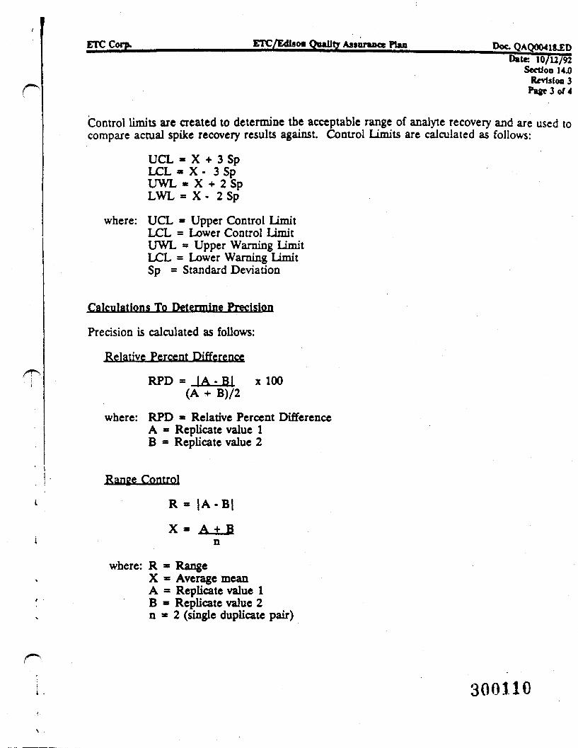
ETC Corp. ETC/E<ii»oo Quality Assurance PUa PQC. QAQ00418JEDDate 10/12/92
Section 14 JORevision 3
P*ge3of4
Control limits are created to determine the acceptable range of analyte recovery and are used tocompare actual spike recovery results against. Control Limits are calculated as follows:
UCL « X + 3 SpLCL « X - 3 SpUWL « X + 2 SpLWL = X - 2 Sp
where: UCL = Upper Control LimitLCL = Lower Control LimitUWL * Upper Warning LimitLCL = Lower Warning LimitSp = Standard Deviation
Calculations To Determine Precision
Precision is calculated as follows:
Relative Percent Difference
RPD = I A . B | x 100(A + B)/2
where: RPD * Relative Percent DifferenceA = Replicate value 1B = Replicate value 2
Range Control
R = |A-B|
X = A + Bn
where: R * RangeX = Average meanA = Replicate value 1B = Replicate value 2n = 2 (single duplicate pair)
300110
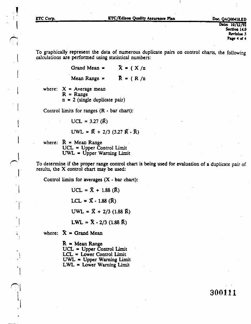
ETC CorP- ETC/EdlsoB Quality As»urmncc PUn Doc. <^AQ004i&JEDbate: 10/12/92
Section 14.0Rcvislo«3
To graphically represent the data of numerous duplicate pairs on control charts, the followingcalculations are performed using statistical numbers:
Grand Mean » X « { X /n
Mean Range = R « { R /n
where: X = Average meanR = Rangen = 2 (single duplicate pair)
Control limits for ranges (R - bar chart):
UCL = 3.27 (R)
LTWL = R + 2/3 (327 R" - R)
where: R » Mean RangeUCL = Upper Control LimitUWL = Upper Warning Limit
To determine if the proper range control chart is being used for evaluation of a duplicate pair ofresults, the X control chart may be used:
Control limits for averages (X - bar chart):
UCL = X + 1.88 (R)
LCL = X - 1.88 (R)
UWL * X + 2/3 (1.88 R)
LWL = X - 2/3 (1.88 R)
where: X » Grand Mean
R * Mean RangeUCL - Upper Control limitLCL = Lower Control LimitUWL « Upper Warning LimitLWL = Lower Warning Limit
300111
IETC Corp. ETC/Edkoo Quality Anuraace PUn Doc. OAOOQ4HLFn
I —————1 Section 15.0
Revision 3Page 1 of 2
CORRECTIVE ACTION
Corrective action is defined as those actions necessary to place any operational process oranalytical system back into its performance specification. It is the objective of the laboratory toimplement appropriate corrective action when and where necessary in an effective and timelymanner.
Corrective actions are initiated at all operational levels within the laboratory, involving analysts,their management, and the quality assurance group in both formal and informal procedures.Analysts are responsible for taking routine informal corrective actions described in the methods.Corrective actions are also initiated externally through project management personnel in local,state, or federal agencies and private sector clients. In each case, after an assessment of the issue,appropriate steps are taken to correct the situation and prevent it from occurring again.
Depending on the severity, corrective actions may be taken at the analyst level, department level,or within the entire laboratory. ETC recognizes the importance of corrective action to maintaina high quality program. In this light, data are reviewed for completeness, accuracy, precision andcompliance with analytical method quality control and project specifications during the datageneration and reporting process.
In general, there are three major types of corrective actions which are initiated at ETC:
To correct sample problems:
Individual samples or matrix problems are usually handled within the analytical laboratory.Corrective actions may include repreparation and re-analysis, clean-ups, dilutions or matrixmodifications. All actions taken are documented with the analytical results.
To correct sample batch problems;
An entire batch of samples may require corrective action if quality control criteria are not met.Laboratory managers are involved in the decisions for actions which may include re-analysis,re-extraction, etc. The quality assurance staff may review both sets of data as applicable todetermine if the problems have been resolved.
To correct systematic problems:
Those problems of a procedural nature are handled by the laboratory managers and qualityassurance group. Major operational changes are made only after approval of the QualityAssurance and Laboratory Operations Managers.
When a situation or issue is identified that requires a corrective action, it is investigated andevaluated using processes that address the requirements for the specific non-conformance found.In a case where there is a lack of existing requirements that may be applied, identification of the
300112
ETC Corp. ETC/Edlsoa Quality Assunmct PUn Doc QAQOCMlgJDUate 10/12/92
Section 154)Revision 3
Page 2 of 2'
requirements is included in the corrective action plan. The corrective action is identified anddocumented through one of several internal report processes.
In the event that any corrective actions are needed because the data quality is in question aboveand beyond those actions stipulated in the analytical methods, the client will be contaaed by ETCto discuss the problem.
\
300113
ETC Corp. ETC/Edlioa Quality AMuraace PUa Doc. QAQ0041gJED- . . .
Section 16.0Revision 3
P»«e 1 of 1
QUALITY ASSURANCE REPORTS TO MANAGEMENT
The objective of the ETC quality assurance program is to ensure that an operational system is inplace which enables management to determine the quality level of all data produced within thelaboratory system. An essential component of the system is the communicadon pathways andfeedback mechanisms which insure that management obtains quality information promptly andconsistently. To achieve this objective, ETC employs informal and formal reporting processes toensure that management is informed of operational quality. This information enables ETC to takecorrective action promptly when required.
Reporting occurs at the following frequency:
o Daily meetings to discuss possible quality assurance problems and proposed solutions,
o Weekly meeting with upper management to discuss laboratory performance, upcoming audits,certification programs, and past audit performances.
o Monthly written status reports to upper management; inclusion of all quality assuranceprograms and pertinent laboratory issues.
o As required, internal departmental audit reports with observations and suggested correctiveaction procedures.
300114
APPENDIX -
FIGURES AND TABLES
300115
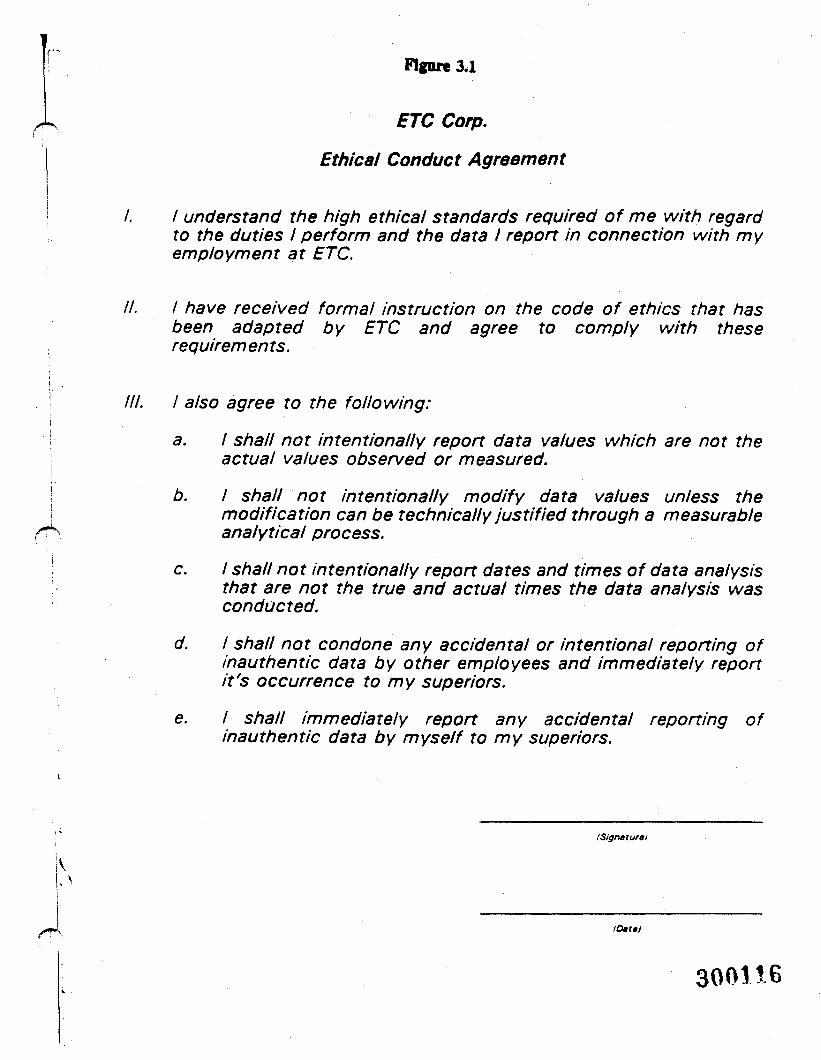
\
Flgnre 3.1
ETC Corp.
Ethical Conduct Agreement
I. I understand the high ethical standards required of me with regardto the duties I perform and the data I report in connection with myemployment at ETC.
II. I have received formal instruction on the code of ethics that hasbeen adapted by ETC and agree to comply with theserequirements.
III. I also agree to the following:
a. I shall not intentionally report data values which are not theactual values observed or measured.
b. I shall not intentionally modify data values unless themodification can be technically justified through a measurableanalytical process.
c. / shall not intentionally report dates and times of data analysisthat are not the true and actual times the data analysis wasconducted.
d. I shall not condone any accidental or intentional reporting ofinauthentic data by other employees and immediately reportit's occurrence to my superiors.
e. I shall immediately report any accidental reporting ofinauthentic data by myself to my superiors.
/Signature i
k
IDattt
300116
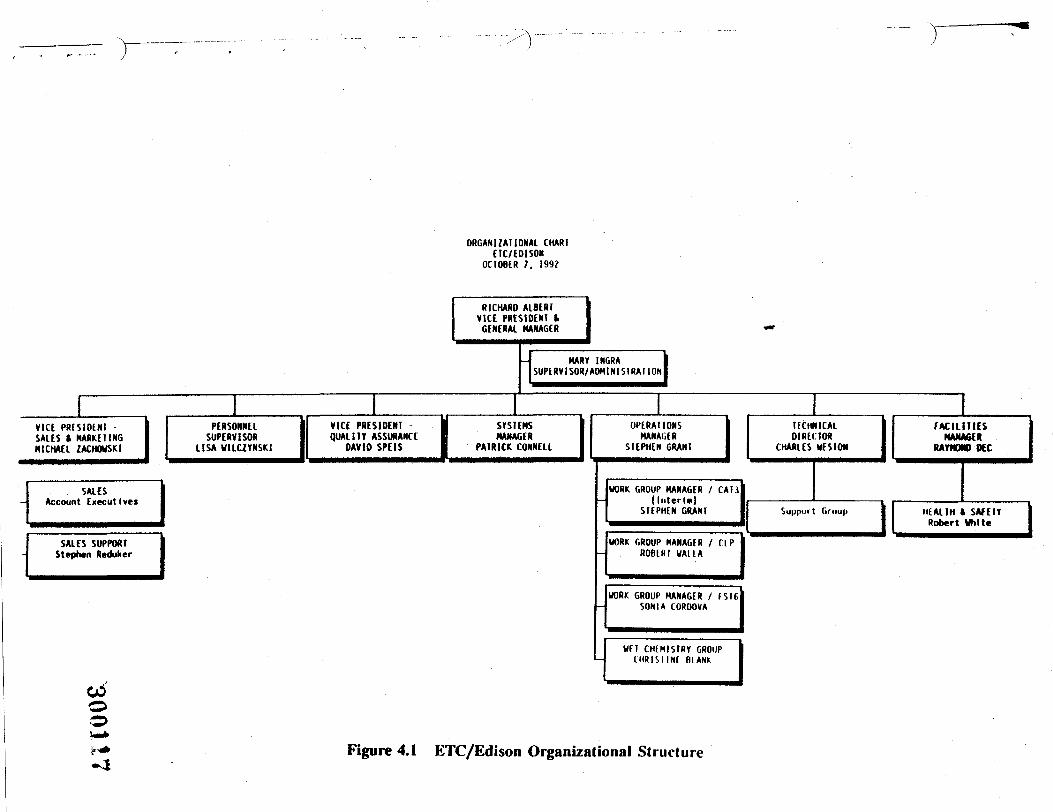
VIC( PHfSIDENISALES » MARKETINGMICHAEL ZACHOVSKI
SALESAccount Executives
SALES SUPPORTStephen Reduker
oo
ORGANIZATIONAL CHAR ICTC/EOISOH
OCTOBER 7. 199?
RICHARD ALBERTVICE PRESIDENT tGENERAL MANAGER
PERSONNELSUPERVISOR
LISA U1LC2YNSK1
VICE PRESIDENT -QUALITY ASSURANCE
DAVID SPEIS IMART INGRA
SUPERVISOR/AOHINIS1RAIION
SYSTEMSMANAGER
PATRICK CONNELL
OPERATIONSMANAGER
STEPHEN GRANT
TECHNICALDIRECTOR
CHARLES UESION
WORK GROUP MANAGER / CAT3(Inter!*)
STEPHEN GRANT
WORK GROUP MANAGER / T I PROfURI UAUA
WORK GROUP MANAGER / (SI6SON IA COROOVA
WFT CWMISIRY GROUPC H R I S I I N f BIANK
FACILITIESMANAGER
RAYWMO DCC
Support Gruup HEALTH t SAfElYRobert White
I" Figure 4.1 ETC/Edison Organizational Structure
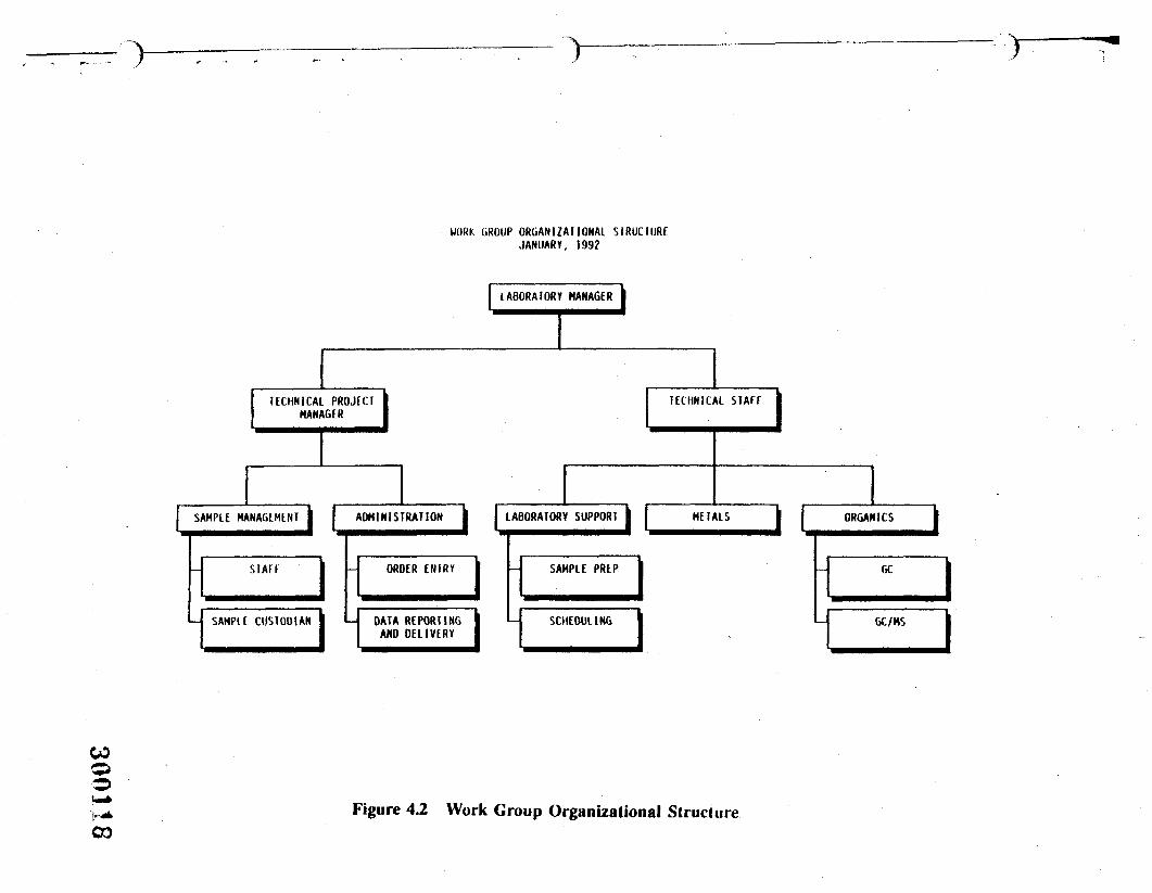
>
COo
WORK GROUP ORGANIZATIONAL SIRUCIURFJANUARY, 1992
TECHNICAL PROJECTMANAGER
SAMPLE MANAGEMENT J I.
LABORATORY MANAGER
ADMINISTRATION
STAIT
SAMPtE CUSTODIAN
ORDER E N T R Y
DATA REPORTINGAND DELIVERY
LABORATORY SUPPORT
SAMPLE PREP
SCHEDULING
TECHNICAL STAFF
METALS J I ORGANICS
GC
GC/MS
COFigure 4.2 Work Group Organizational Structure
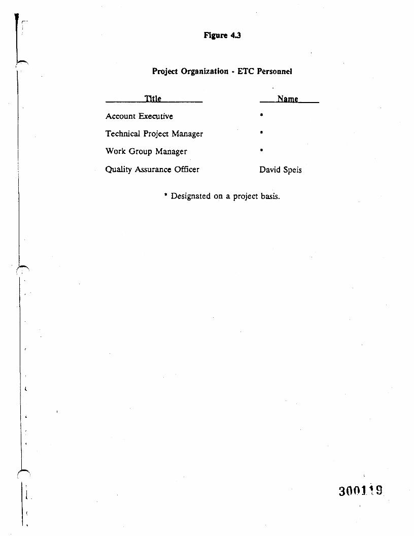
Figure
Project Organization • ETC Personnel
______ Title ______ Name
Account Executive *
Technical Project Manager *
Work Group Manager *
Quality Assurance Officer David Speis
* Designated on a project basis.
300H9
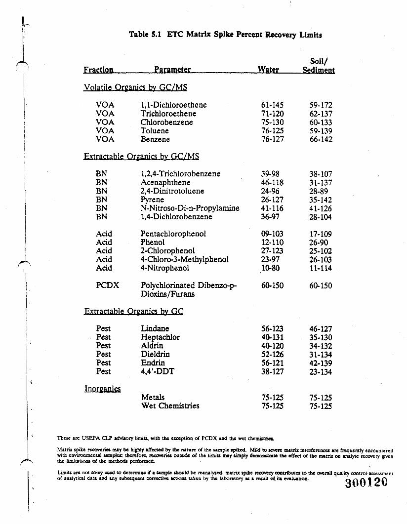
Table 5.1 ETC Matrix Spike Percent Recovery Limits
Fraction, Parameter Water
Volatile Organics by GC/MS
VOA 1,1-DichloroetheneVOA TrichloroetheneVOA ChlorobenzeneVOA TolueneVOA Benzene
Extractable Organics by GC/MS
BN 1,2,4-TrichlorobenzeneBN AcenaphtheneBN 2,4-DinitrotolueneBN PyreneBN N-Nitroso-Di-n-PropylamineBN 1,4-Dichlorobenzene
Acid PentacblorophenolAcid PhenolAcid 2-ChlorophenolAcid 4-Chloro-3-MethylphenolAcid 4-Nitrophenol
PCDX Polychlorinated Dibenzo-p-Dioxins/Furans
Extractable Qrganics bv GC
PestPestPestPestPestPest
LindaneHeptachlorAldrinDieldrinEndrin4,4'-DDT
MetalsWet Chemistries
61-14571-12075-13076-12576-127
60-150
56-12340-13140-12052-12656-12138-127
75-12575-125
Soil/Sediment
59-17262-13760-13359-13966-142
39-9846-11824-9626-12741-11636-97
09-10312-11027-12323-9710-80
38-10731-13728-8935-14241-12628-104
17-10926-9025-10226-10311-114
60-150
46-12735-13034-13231-13442-13923-134
75-12575-125
These are USEPA CLP advisory limits, with the exception of PCDX and the wet chemistries.
Matrix spike recoverie* may be highly affected by the nature of the sample spiked. Mild to severe matrix interference* are frequently encounteredwith environmental samples; therefore, recoveries outside of the limits may simpty demonstrate the effect of the matrix on analyte recovery giventhe limitations of the methods performed.
Limits are not sotey used to determine if a sample should be reanalyzed; matrix spike recovery contribute* to the overall quality control-assessmentof analytical data and any subsequent corrective actions taken by the laboratory as a result of it* evaluation. O A A 1 Of)
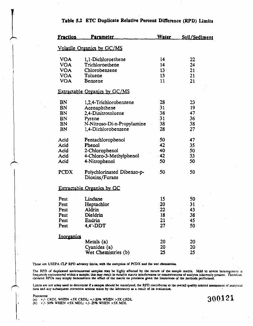
Table 5.2 ETC Duplicate Relative Percent Difference (RPD) Limits
Fraction Parameter Water Soil/Sediment
Volatile Organics by GC/MS
VOA 1,1-DichloroetheneVOA TrichloroetheneVOA ChlorobenzeneVOA TolueneVOA Benzene
Extractable Organics by GC/MS
BN 1,2,4-TrichlorobenzeneBN AcenaphtheneBN 2,4-DinitrotolueneBN PyreneBN N-Nitroso-Di-n-PropylamineBN 1,4-Dichlorobenzene
Acid PentachlorophenolAcid PhenolAcid 2-ChlorophenolAcid 4-Chloro-3-MethylphenolAcid 4-Nitrophenol
PCDX Polychlorinated Dibenzo-p-Dioxins/Furans
Extractable Organics by GC
PestPestPestPestPestPest
LindaneHeptachlorAldrinDieldrinEndrin4,4'-DDT
Metals (a)Cyanides (a)Wet Chemistries (b)
1414131311
283138313828
5042404250
50
152022182127
202025
These are USEPA CLP RPD advisory limits, with the exception of PCDX and the wet chemistries.
2224212121
231947363827
4735503350
50
503143384550
202025
The RPD of duplicated environmental samples may be highly affected by the nature of the sample matrix. Mild to severe heterogeneity isfrequently encountered within a sample; this may result in variable matrix interferences or coocentratioas of analytes inbereatly present. Therefore,elevated RPDs may simply demonstrate the effect of the matrix on precision given the limitations of the methods performed.
Limits are not sotey used to determine if a sample should be reanalyzed; the RPD contnbutes to the overall quality control assessment of analyticaldata and any subsequent corrective actions taken by the laboratory as a result of its evaluation.
Footnotes:(a) +/- CRDL WHEN <5X CRDL; +/-20% WHEN >5X CRDL(b) +/-SO%WHEN <5XMDU +/-25%WHEN >5XMDL
300121
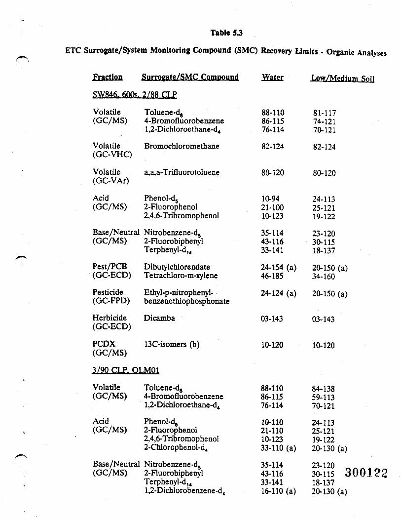
Table 5 J
ETC Surrogate/System Monitoring Compound (SMC) Recovery Limits • Organic Analyses
Fraction Surrogate/SMC Compound
SW846. 600s. 2/88 CLP
Volatile Toluene-d8(GC/MS) 4-Bromofluorobenzene
l,2-Dichloroethane-d4
Volatile Bromochloromethane(GC-VHC)
Volatile a,a,a-Trifluorotoluene(GC-VAr)
Acid Phenol-d5(GC/MS) 2-Fluorophenol
2,4,6-Tribromophenol
Base/Neutral Nitrobenzene-d5(GC/MS) 2-Fluorobiphenyl
Terphenyl-d14
Pest/PCB Dibutylchlorendate(GC-ECD) Tetrachloro-m-xylene
Pesticide Ethyl-p-nitrophenyl-(GC-FPD) benzenethiophosphonate
Herbicide Dicamba(GC-ECD)
PCDX 13C-isomers (b)(GC/MS)
3/90 CLP. OLM01
Volatile Toluene-d^(GC/MS) 4-Bromofluorobenzene
l,2-Dichloroethane-d4
Acid Phenol-d5(GC/MS) 2-Fluorophenol
2,4,6-Tribromophenol2-Chlorophenol-d4
Base/Neutral Nitrobenzene-d5(GC/MS) 2-Fluorobiphenyl
Terphenyl-d14l,2-Dichlorobenzene-d4
88-11086-11576-114
82-124
80-120
10-9421-10010-123
35-11443-11633-141
24-154 (a)46-185
24-124 (a)
03-143
10-120
88-11086-11576-114
10-11021-11010-12333-110 (a)
35-11443-11633-14116-110 (a)
_kOf •!/ I ' tkUll
81-11774-12170-121
82-124
80-120
24-11325-12119-122
23-12030-11518-137
20-150 (a)34-160
20-150 (a)
03-143
10-120
84-13859-11370-121
24-11325-12119-12220-130 (a)
23-120 f30-115 C18-13720-130 (a)
300122
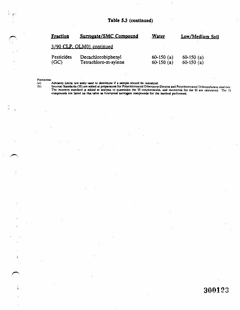
Table S3 (continued)
Fraction Suirpgate/SMC Compound
3/90 CLP. OLM01 continued
Pesticides Decachlorobiphenyl(GC) Tetrachloro-m-xylene
Water
60-150 (a)60-150 (a)
Low/Medium Soil
60-150 (a)60-150 (a)
Footnotes:(a) Advisory limits; not toley used to determine if a sample should be reanalyzd.(b) Internal Standards (IS) are added at preparation for Potychlorinated Dibenzo-p-Dionns and Polychlonnited Dibetuofurans analvsss
The recovery standard is added at analysis to qutnnute the IS concentration, and recoveries for the IS are calculated. The IScompounds are listed on this table as functional surrogate compounds for the method performed.
300123
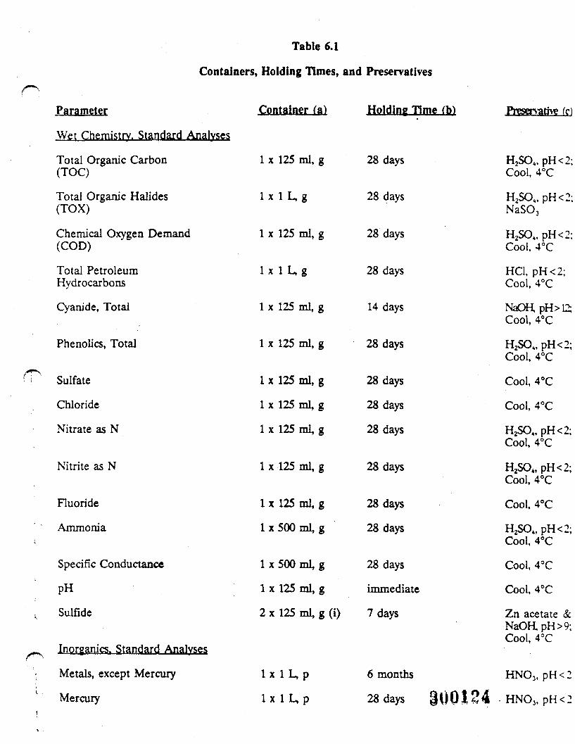
Table 6.1
Containers, Holding Times, and Preservatives
Parameter Container (a) Holding Time (b)
Metals, except Mercury
Mercury
Preservatte (cl
Wet Chemistry. Standard Analyses
Total Organic Carbon(TOC)
Total Organic Halides(TOX)
Chemical Oxygen Demand(COD)
Total PetroleumHydrocarbons
Cyanide, Total
Phenolics, Total
Sulfate
Chloride
Nitrate as N
Nitrite as N
Fluoride
Ammonia
Specific Conductance
PH
Sulfide
Inorganics. Standard Analyses
1 x 125 ml, g
I x l U g
1 x 125 ml, g
I x l U g
1 x 125 ml, g
1 x 125 ml, g
1 x 125 ml g
1 x 125 ml g
1 x 125 ml g
1 x 125 ml, g
1 x 125 ml g
1x500 ml, g
1 x 500 ml g
1 x 125 ml g
2 x 125 ml g (i)
28 days
28 days
28 days
28 days
14 days
28 days
28 days
28 days
28 days
28 days
28 days
28 days
28 days
immediate
7 days
H2SO4, pH<2;Cool, 4°C
H2SOt, pH<2;NaSO3
H2SO4, pH<2:Cool, 4°C
HC1, pH<2;Cool, 4°C
NaOHpH>12;Cool, 4°C
H2SOt,pH<2;Cool, 4°C
Cool, 4°C
Cool, 4°C
H2SOt, pH<2;Cool, 4°C
H2SO4, pH<2;Cool, 4°C
Cool, 4°C
H2S04,pH<2;Cool, 4°C
Cool, 4°C
Cool, 4°C
Zn acetate &NaORpH>9;Cool, 4°C
l x l L , p
6 months HNO3, p H < 2
28 days 30Q124 HNO3, p H < 2
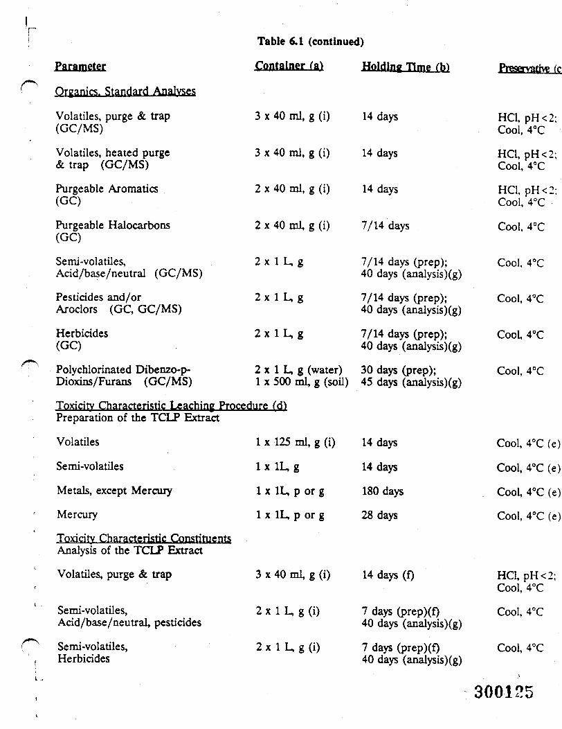
Parameter
Table 6,1 (continued)
Container (a) Holding Time fh) Preservative (c
Organic^, Standard Analyses
Volatiles, purge & trap(GC/MS)
Volatiles, heated purge& trap (GC/MS)
Purgeable Aromatics(GC)
Purgeable Halocarbons(GC)
Semi-volatiles,Acid/base/neutral (GC/MS)
Pesticides and/orAroclors (GC, GC/MS)
Herbicides(GC)
3 x 40 ml, g (i)
3 x 40 mi, g (i)
2 x 40 ml, g (i)
2 x 40 ml, g (i)
2x 1 L,g
2 x l L , g
2 x l L , g
Polychlorinated Dibenzo-p- 2 x 1 L, g (water)Dioxins/Furans (GC/MS) 1 x 500 ml, g (soil)
Toxicity Characteristic Leaching Procedure (d)Preparation of the TCLP Extract
Volatiles
Semi-volatiles
Metals, except Mercury
Mercury
Toxicitv Characteristic Constituents,Analysis of the TCLP Extract
Volatiles, purge & trap
Semi-volatiles,Acid/base/neutral, pesticides
Semi-volatiles,
1 x 125 ml, g (i)
lx!L,g
1 x 1L, p or g
1 x 1L, p or g
3 x 40 ml, g (i)
2 x 1 L, g (i)
2 x 1L, g <i)
14 days
14 days
14 days
7/14 days
7/14 days (prep);40 days (analysis)(g)
7/14 days (prep);40 days (analysis)(g)
7/14 days (prep);40 days (analysis)(g)
30 days (prep);45 days (analysis)(g)
14 days
14 days
180 days
28 days
14 days (0
7 days (prep)(f)40 days (analysis)(g)
7 days (prep)(f)
HC1, pH<2;Cool, 4°C
HCl, pH<2;Cool, 4°C
HCl, pH<2;Cool, 4°C
Cool, 4°C
Cool, 4°C
Cool, 4°C
Cool, 4°C
Cool, 4°C
Cool, 4°C (e)
Cool, 4°C (e)
Cool, 4°C (e)
Cool, 4°C (e)
HCl, pH<2;Cool, 4°C
Cool, 4°C
Cool, 4°CHerbicides 40 days (analysis)(g)
300125
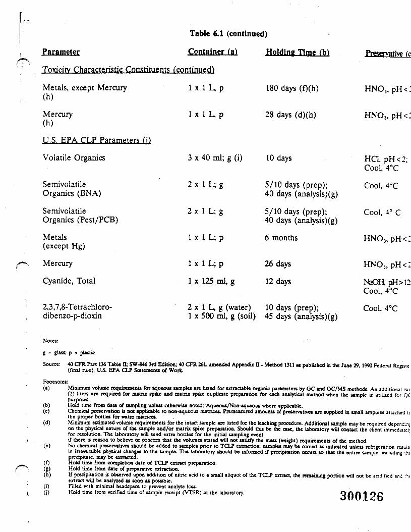
Table 6.1 (continued)
Parameter Container fa) Holding Time Cbl
Toxicit Characteristic Constituents (continued
180 days (0(h)Metals, except Mercury(h)
Mercury(h)
U.S. EPA CLP Parameters (j)
Volatile Organics
SemivolatileOrganics (BNA)
SemivolatileOrganics (Pest/PCB)
Metals(except Hg)
Mercury
Cyanide, Total
2,3,7,8-Tetrachloro-dibenzo-p-dioxin
I x l L , p
1 x 1 L, p
3 x 40 ml; g (i)
2 x 1 L; g
2 x 1 L; g
1 x 1 L; p
1 x 1 L; p
1 x 125 ml, g
28 days (d)(h)
10 days
5/10 days (prep);40 days (analysis)(g)
5/10 days (prep);40 days (analysis)(g)
6 months
26 days
12 days
Preservative fc
HNO3, pH<:
HN03, pH<:
2 x 1 L, g (water) 10 days (prep);1 x 500 ml, g (soil) 45 days (analysis)(g)
HC1, pH<2;Cool, 4°C
Cool, 4°C
Cool, 4° C
HN03 ,pH<-
HNO3, p H < 2
NaOHpH>12Cool, 4°C
Cool, 4°C
Notes:
g * glass; p » plastic
Source: 40 CFR Part 136 Table II; SW-846 3rd Edition; 40 CFR 261, amended Appendix D - Method 1311 as published in the June 29,1990 Federal Renste(final rule), VS. EPA CLP Statement* of Work.
Footnotes:(a) Minimum volume requirements for aqueous samples are listed for extractable organic parameters by GC and GC/MS methods. An additional t»-t
(2) liters are required for matrix spike and matrix spike duplicate preparation for each analytical method when the sample is utilized for QCpurposes.
(b) Hold time from date of sampling unless otherwise noted; Aqueous/Non-aqueous where applicable.(c) Chemical preservation it not applicable to non-aqueous matrices. Premeasured amounts of preservatives are supplied in small ampules attached tc
the proper bottles for water matrices.(d) Minimum estimated volume requirements for the intact sample are listed for the leaching procedure. Additional sample may be required dependmj
on the physical nature of the sample and/or matrix spike preparation. Should this be the case, the laboratory will contact the client immediate!'for resolution. The laboratory will send extra bottles for the initial sampling eventif there is reason to believe or concern that the volumes stated will not satisfy the mass (weight) requirements of the method.
(e) No chemical preservatives should be added to samples prior to TCLP extraction; samples may be cooled as indicated unless refrigeration result:in irreversible physical change* to the sample. The laboratory should be informed if precipitation occurs so that the entire sample, including ;h<precipitate, may be extracted.
(0 Hold time from completion date of TCLP extract preparation.(g) Hold time from date of preparative extraction.(h) If precipitation is observed upon addition of nitric acid to a small aliquot of the TCLP extract, the remaining portion will not be acidified anJ :N
extract will be analyzed as scon as possible.(i) Filled with minimal headspace to prevent analyte loss.(j) Hold time from verified time of sample receipt (VTSR) at the laboratory. Q A A 1 O CJ
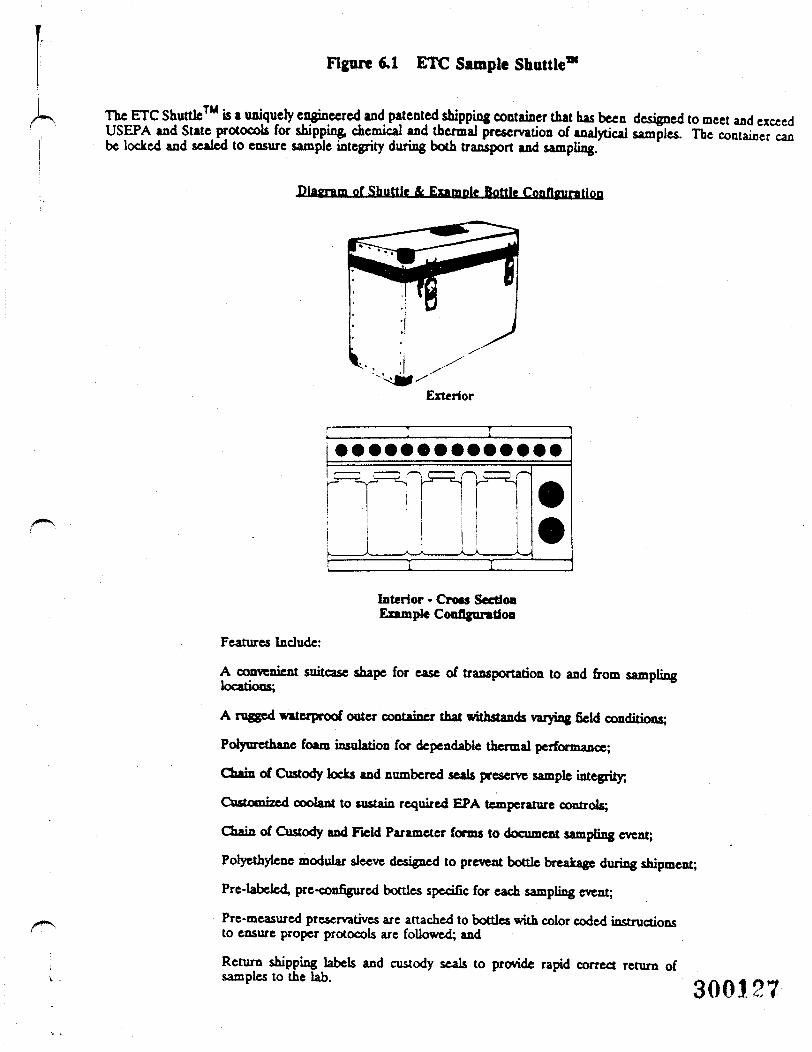
Figure 6.1 ETC Sample Shuttle™
The ETC Shuttle™ is a uniquely engineered and patented shipping container that has been designed to meet and exceedUSEPA and State protocols for shipping, chemical and thermal preservation of analytical samples. The containerbe locked and sealed to ensure sample integrity during both transport and sampling.
ale Bottle Configuration
can
Exterior
Interior • Cross SectionExample Configuration
Features Include:
A convenient suitcase shape for ease of transportation to and from samplinglocations;
A rugged waterproof outer container that withstands varying field conditions;
Poryurethane foam insulation for dependable thermal performance;
Chain of Custody locks and numbered seals preserve sample integrity,
Customized coolant to sustain required EPA temperature controls;
Chain of Custody and Field Parameter forms to document sampling event;
Polyethylene modular sleeve designed to prevent bottle breakage during shipment;
Pre-labeled, pre-configured bottles specific for each sampling event;
Pre-measured preservatives are attached to bottles with color coded instructionsto ensure proper protocols are followed; and
Return shipping labels and custody seals to provide rapid correct return of-,,1. »*.!*. 300127-
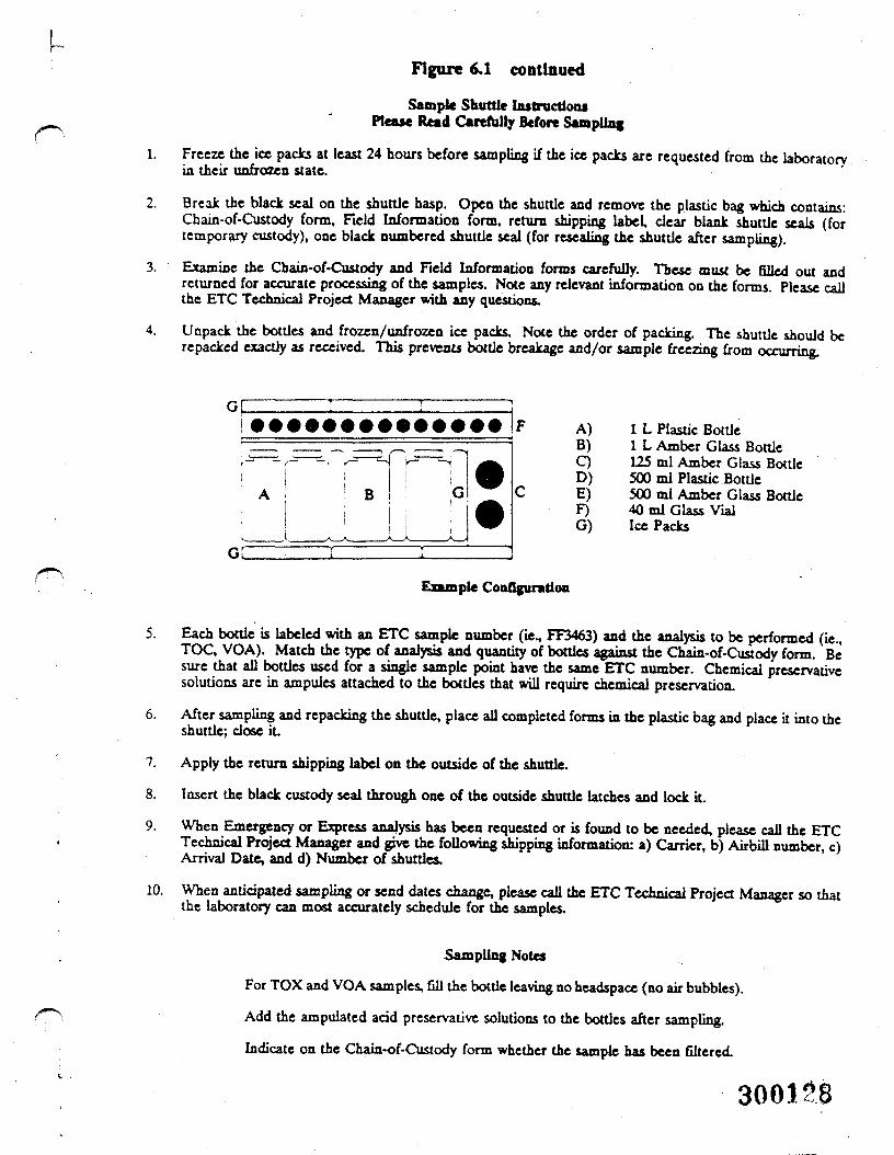
u
1.
3.
4.
Figure 6.1 continued
Sample Shuttle Instruction*' Please Read Carefully Before Sampling
Freeze the ice packs at least 24 hours before sampling if the ice packs are requested from the laboratoryin their unfrozen state.
2. Break the black seal on the shuttle hasp. Open the shuttle and remove the plastic bag which contains:Chain-of -Custody form. Field Information form, return shipping label, clear blank shuttle seals (fortemporary custody), one black numbered shuttle seal (for repealing the shuttle after sampling)
Examine the Chain-of-Custody and Field Information forms carefully. These must be filled out andreturned for accurate processing of the samples. Note any relevant information on the forms. Please callthe ETC Technical Project Manager with any questions.
Unpack the bottles and frozen/unfrozen ice packs. Note the order of packing. The shuttle should berepacked exactly as received. This prevents bottle breakage and/or sample freezing from occurring.
6.
7.
8.
A) 1 L Plastic BottleB) 1 L Amber Glass BottleC) 125 ml Amber Glass BottleD) 500 ml Plastic BottleE) 500 ml Amber Glass BottleF) 40 ml Glass VialG) Ice Packs
Example Configuration
5. Each bottle is labeled with an ETC sample number (ie., FF3463) and the analysis to be performed (ie.,TOC, VOA). Match the type of analysis and quantity of bottles against the Chain-of-Custody form. Besure that all bottles used for a single sample point have the same ETC number. Chemical preservativesolutions are in ampules attached to the bottles that will require chemical preservation.
After sampling and repacking the shuttle, place all completed forms in the plastic bag and place it into theshuttle; dose it.
Apply the return shipping label on the outside of the shuttle.
Insert the black custody seal through one of the outside shuttle latches and lock it.
9. When Emergency or Express analysis has been requested or is found to be needed, please call the ETCTechnical Project Manager and give the following shipping information: a) Carrier, b) Airbill number, c)Arrival Date, and d) Number of shuttles.
10. When anticipated sampling or send dates change, please call the ETC Technical Project Manager so thatthe laboratory can most accurately schedule for the samples.
Sampling Notes
For TOX and VOA samples, Gil the bottle leaving no headspace (no air bubbles).
Add the ampulated acid preservative solutions to the bottles after sampling.
Indicate on the Chain-of-Custody form whether the sample has been filtered.
300128
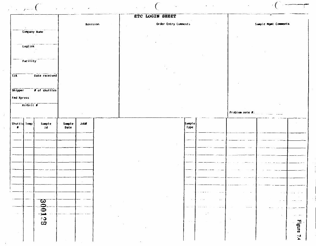
•cCompany Name
Log!ink
F a c i l i t y
T/A Date received
Shipper * of shuttles
Fed Xpress
A i r b i l l *
Shut tlt|*
Temp SampleId
o-r-*
CO
Revision
SanpleDate
Job*
ETC LOGIN SHEET
Order Entry Comments
SampleType
Hgmt Caments
Problem note t:
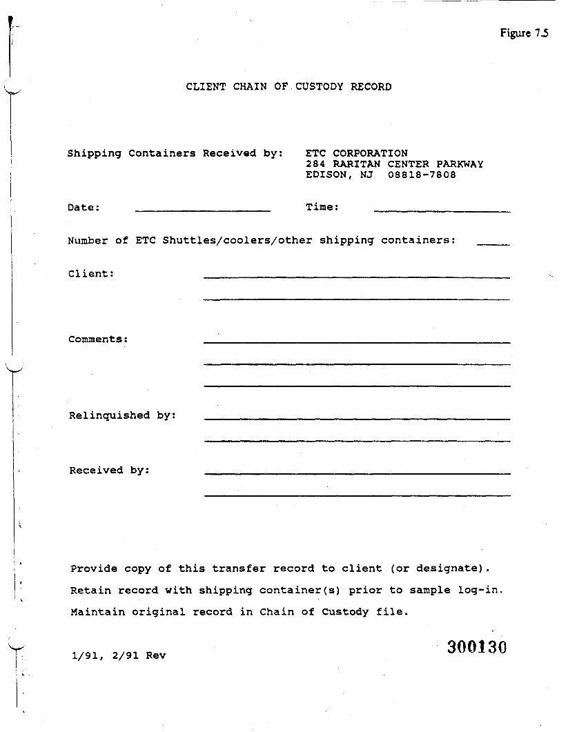
Figure 7.5
CLIENT CHAIN OF CUSTODY RECORD
Shipping Containers Received by: ETC CORPORATION284 RARITAN CENTER PARKWAYEDISON, NJ 08818-7808
Date: ________________ Time: ______________
Number of ETC Shuttles/coolers/other shipping containers:
Client: _____________________________
Comments:
Relinquished by;
Received by:
Provide copy of this transfer record to client (or designate) .
Retain record with shipping container(s) prior to sample log-in.
Maintain original record in Chain of Custody file.
Rev
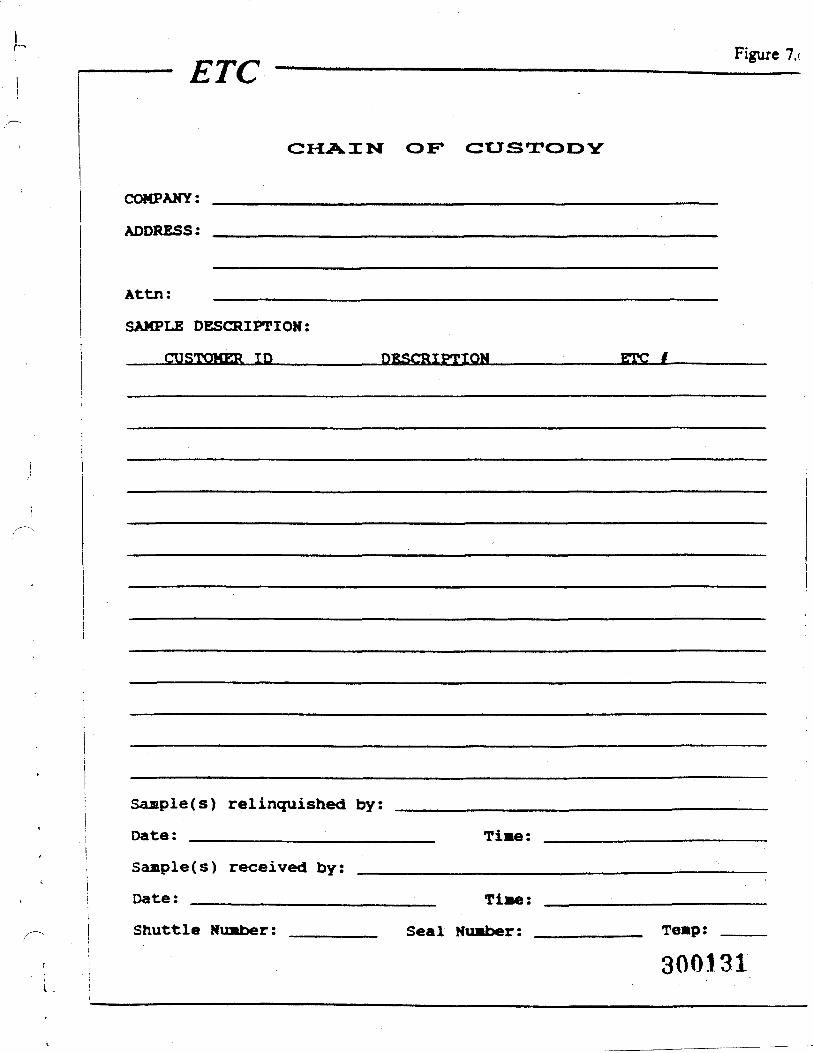
ETC Figure 7.t
CHAIN OF CUSTODV
COMPANY:
ADDRESS:
Attn:
SAMPLE DESCRIPTION:
CUSTOMER ID DESCRIPTION ETC
Seuaple(s) relinquished by:
Date: ________________ Ti
Sanple(s) received by:
Date: _____________ TiShuttle Number: Seal Number: Te»p:
300131
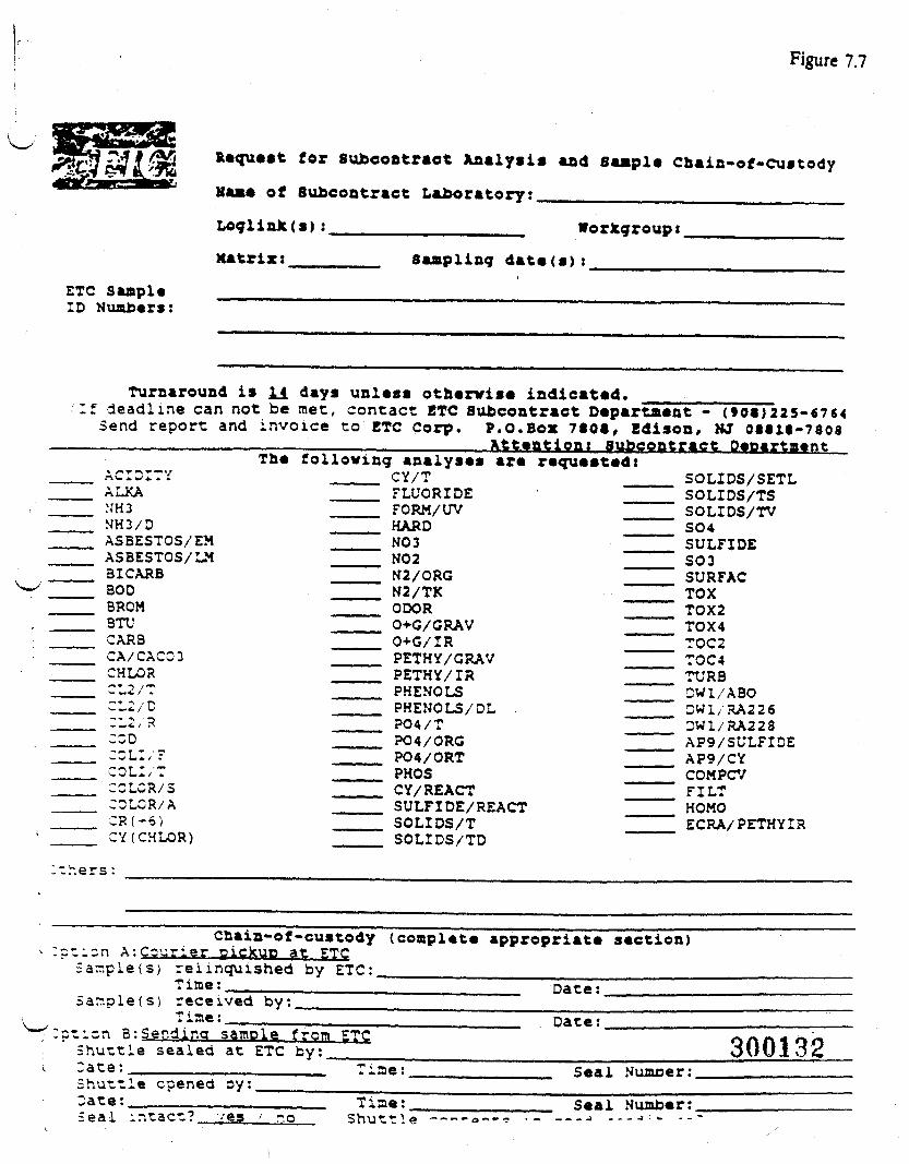
Figure 7.7
Request for subcontract Analyst* and sample Cnain-of-custody
Name of subcontract Laboratory:______________________
LoglinJc(s) :___xatrix:
Workgroup:Sampling dats(s):
ETC saaple10 Nuabers:
Turnaround is H days unless othervise indicated. ___________________if deadline can not be met, contact ETC Subcontract Department - (SOS)225-«764
Send report and invoice to ETC Corp. P.O.Box 7SOt, Edison, KJ OMia-7808
ACIDITY____ ALKA
NH3KH3/DASBESTOS/EMASBESTOS/LM3 I CARSBODBROM3TUCARBCA/CAC03CHLORCL2/TCL2/D:L2, R
____ COD•1C LI / ~
____ COLI/TCCLCR/3
____ CCLCR/A___ _ i r .___ *"•" *^ \ ™ '
The following analyses are requested:____ CY/T
FLUORIDE ' ———FORM/UVHARD ———
______ N03NO 2N2/ORG ———N2/TK
____ ODOR ———0+G/GRAV ———0+G/IRPETHY/GRAVPETHY/IR
____ PHENOLS____ PHENOLS/DL .
P04/T_____ P04/ORG
P04/ORTPHOSCY/ REACT ———
____ SULFIDE/REACT____ SOLIDS/T
SOLIDS/SETLSOLIDS/TSSOLIDS/TVSO4SULFIDES03SURFACTOXTOX2TOX4TOC2TOC4TURBDW1/ABODW1/RA226DW1/RA228AP9/SULFIDEAP9/CYCOMPCVFILTHOMOECRA/PETHYIR
Y( CHLOR) SOLIDS/TD
:thers:
Chain-of-custody (compl«t« appropriate section)tisn A;Csurier piekuo at ETC5ar.ple(s; relinquished by ETC:____ ___________________
Time:.^————.___________________ Date:_______Sar.plefs) received by:______________________ ____
rime:tion 3;Ser.dina sample from ETCShuttle sealed at ETC by:___"ate: ____________
Date:
300132Shuttle opened by:Date:__________
lae: Seal Numoer:
Seal intact? noTiae:Shuttle
Seal Humber:.- - J _ ̂ - j -' «. - -
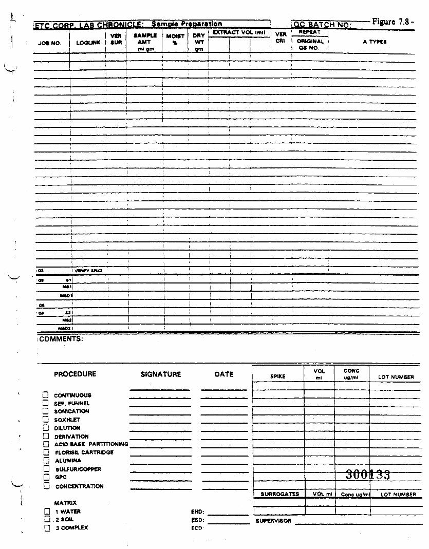
,L!ETC COR
JOiNO.
P. LAB CHBQfilI VW
LOOUNK I SUR
I!
CLE: S»TVDlePr«D«ration i !QC BATCH NO: "HgUie/.«-
SAMPtfAMTml gm
MOIST%
DRYWTgm
i
EXTRACT VOL (ml) , VEM ' REPEAT ;
1 CM 1 OmOINAL i A TYPES• 1 OS NO. i
i . !I .
•
a» (21MUl I i
M«OJ I
I COMMENTS:
PROCEDURE SIGNATURE DATE
D CONTINUOUS!H SEP. FUNNELU SONICATJOND SOXHIETQ DlitmONG DERIVATIONO ACID BASE PARTITIONINGG Fiomsa. CARTRIDGEG ALUMINAG SULFUR/COPPERn OPCG CONCENTRATION
MATRIXG 1 WATER EHD:U 2 SOtt. ESD:PI 3 COMPLEX ECO
SPIKE
1 SURROGATESi
SUPERVISOR
VOLml
VOL ml
CONCug/ml
-5t̂
Cone ug/m
LOT NUMBER
^3 ———LOT NUMBER
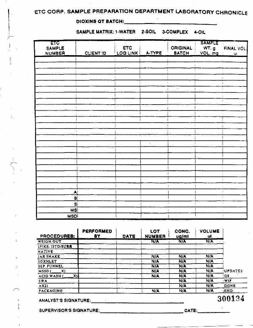
ETC CORP. SAMPLE PREPARATION DEPARTMENT LABORATORY CHRONICLE
DIOXINS QT BATCH:____________________,
SAMPLE MATRIX: 1-WATER 2-SOIL 3-COMPLEX 4-OIL
ETCSAMPLENUMBER
ETCCLIENT ID j LOG LINK A-TYPE
:• SAMPLE ,ORIGINAL WT. g FINAL VOL
BATCH ; VOL. ma ul! ; ' 1 : :
1
I 1 j
! i; i
i
!
1 i ! •t !
1 ' it ii i
i
lAlBiSI
MSIMSDl
|i
i
!
1 '
PROCEDURES:WEIGH OUTSPIKE: ISTD/SURJlNATIVEJAR SHAKESOXHLETSEP. FUNNELMSSGf X)ACID WASH ( X)SWAAX21PACKAGING
PERFORMEDBY DATE
LOTNUMBER
N/A
N/AN/AN/AN/AN/A
N/A
CONC.ua/ml
N/A
N/AN/AN/AN/AN/AN/AN/AN/A
VOLUMEul
N/A
N/AN/AN/AN/AN/AN/AN/AN/A
UPDATES:QSWIPDONEEHD: .
ANALYST'S SIGNATURE: 300134SUPERVISOR'S SIGNATURE: DATE:
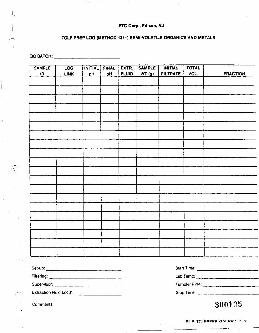
ETC Corp., Edison, NJ
TCLP PREP LOG (METHOD 1311) SEMI-VOLATILE ORGANICS AND METALS
QC BATCH:
SAMPLEID
LOGLINK
INITIALPH
FINALPH
EXTR.FLUID
Set-up:
Filtering:
Supervisor:
Extraction Ruid Lot #:
SAMPLEWT(g)
INITIALFILTRATE
TOTALVOL. FRACTION
Start Time:
Lab Temp:
Tumbler RPM:
Stop Time:
Comments: 300135
FILE
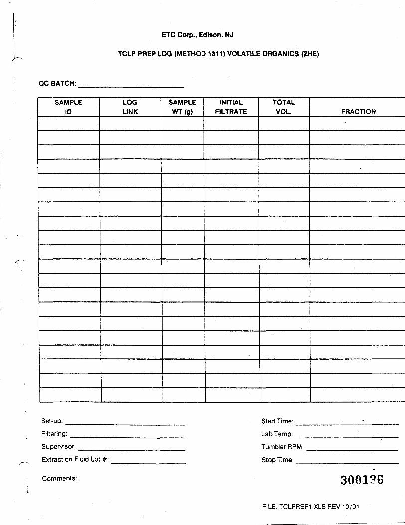
ETC Corp., Edison, NJ
TCLP PREP LOG (METHOD 1311) VOLATILE ORGANICS (ZHE)
QC BATCH:
SAMPLEID
Set-up:
Filtering:
Supervisor:
Extraction Fluid Lot
LOGLINK
#:
SAMPLEWT(g)
INITIALFILTRATE
TOTALVOL.
Start Time:
Lab Temp:
Tumbler RPM:
Stop Time:
FRACTION
Comments: 300136
FILE: TCLPREP1 .XLS REV 10/91
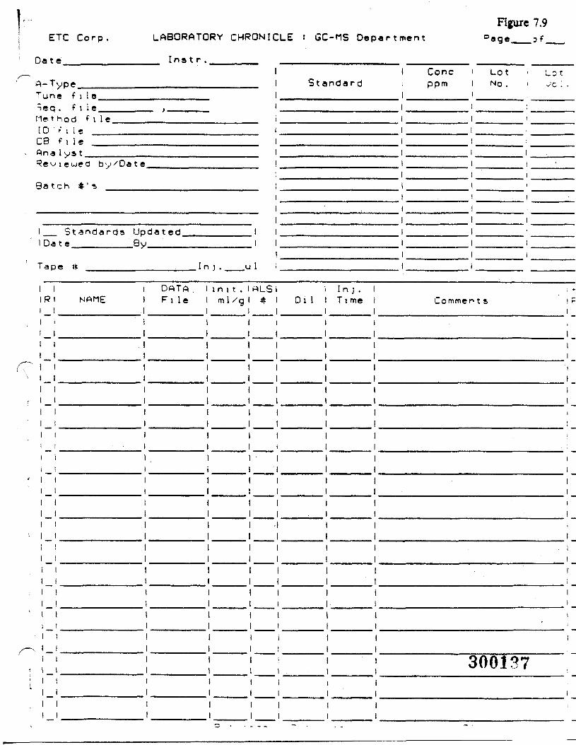
ETC Corp.
Da t e______
LABORATORY CHRONICLE s GC-MS Department
Instr._______ _________________ _____
Figure 7.9°age__af_
I Cone LotA-Type__Tune f i 1 eTeq. ( i I eMethod fiID f i l eCB f i l eAna I ys t.
StandardI
Reviewed by'Date.
Batch *'-, _____
Standards UpDa te BVJ
"a DO #
1 iR l NAHE
!1I1111I11111it1111!
t
!!
1 1
1 11 !1 !! 11 !1 !1 11 11 11 11 I1 1! 1
dated
Ir
DATAFi le
1!1111111
1 . L
in i t .m 1 /g
11
1
rtLS*
•
1Di I
In).T i me
1 11 111 i1 i1 !
I *
Commen t s ! Pi
11Ii111i
ii11i1
11!
11
11j
1
300137i
ETC Corp.
Date
LABORATORY CHRONICLE
In»t r.
GC DepartmentFigure 7.10
Page__of_
iA-Tvoe . ,„., 1 StandardCo 1 umn 1Co 1 . Lot !Ca 1 ib. Fi le 1Seq . F i i e . IMethod f i l e 1ID f i 1* 1Con f i gu . f 1 1 e , 1Ana lus t . 1Pe^iewed bv/Date 1Batch #'s 1
11
1 Standard Undated 1 1iDate B v I I
1Tape # I n i . u I i
Cone .ppm
LotNo.
(Cone . ! LotStandard! ppm i NO.
I i1 i1 i1 ii i1 !1 11 i1 !1 i1 11 11 !1 i1 :1 1
I iI R I NAME1 11 11 11 11 11 11 !1 11 1I 1i 11 1! 1
i 1
! 11 11 I1 11 1! 11 11 1i I1 11 11 1! 11 1i 11 11 11 !1 1I 1! 1I 1I 1
___ DataDetec . 1
Fi ie ___D e t e c . 2
i n i t .m 1 /g
AL3it Di I Comments
.
300138
ETC Corp.
Dat e
LABORATORY CHRONICLE : LC Department
Instr.
Figure 7.11Page__of_..
»-T
ieq1e ̂[0:Bin a^£ \
3a»
voe
. f i l e
f i 1*f i l e1 VJS t
' i ewed by xDa t e
ch #' s
Stanoards Uo datedDate Bv
11
" a D e # I n i . ul
iR
t
' —
I
NAME
! II I: i
i
DATAFt le
1ii
II
in i t .ml /g
—————
ALS
' 1 Cone i Lot iStandard ppm < NO.
;
I
! 1
!
i
i
l
:i
O i l
i
Comment,
3U0139
ETC Figure 7.
SAMPLE PREPARATION LOG - METALS
BATCH* MATRIX
Sample ID
(LCS) Control(PB) Q -1(BS) Q -A1
ICPInitial Final
Fumac*Initial Final
MercuryInitial Final
BoronInitial Final
Mainx spwe ana uupncaie irwornvDon
Sample 10-1
(MS) A1(D) -2
Sample 10-1
{MS) A1(D) -2
Analyst:Date:
300140
ETCFigure 7.12
LOG LINK.
LABORATORY CHRONICLE: Metals Department
Samples.
Chemist DateHg Prep
AA Prep
ICAP Prep
Lab Supervisor Date.
ETC FORM
300141
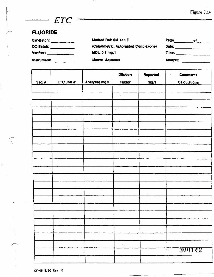
ETCFigure 7.14
FLUORIDEQW-8atcn:QC~Batcn:Verified:
Instrument:
Seq#
Method Reft SM 413 E Page of(CoJorimetric, Automated Conplexone) Date:MDL 0.1 mg/l Time:
Matrix: Aqueous Analyst:
ETC Job* Anatyzadmg/t
Dilution
Factor
Reported
mg/l
Comments
Calculations
3UU14£
CV-06 5/90 Rev. 0
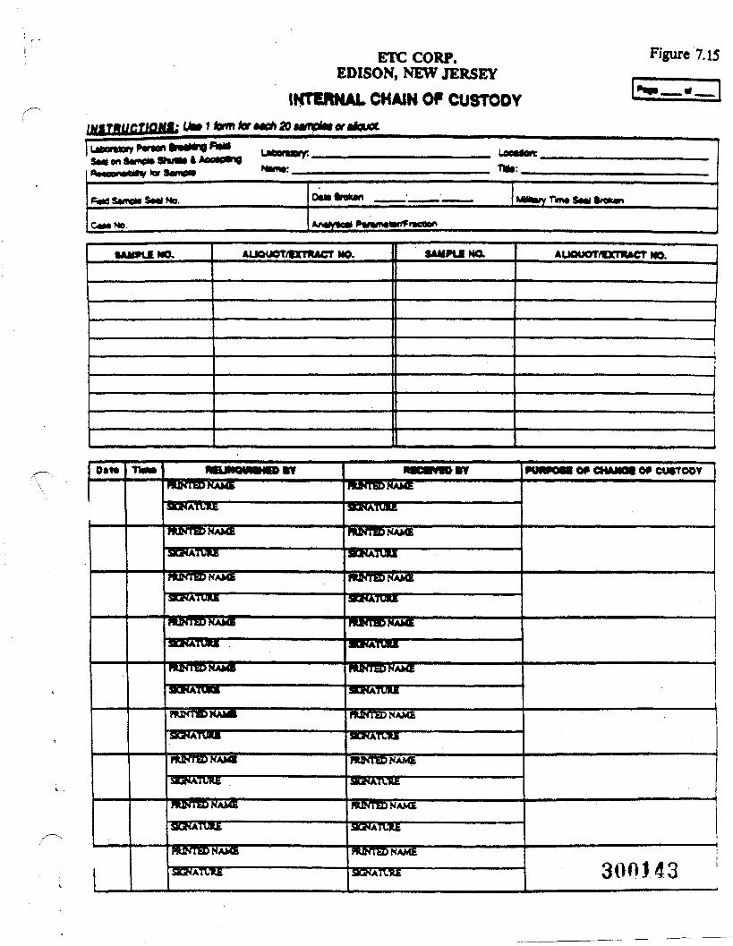
ETC CORP.EDISON, NEW JERSEY
INTERNAL CHAIN OP CUSTODYINITHUCTIOM: Ut» f torn tor MCfi SO MffBtet or tiauaL
Figure 7.15
3«« wi temp*
CM* No. Anoyte* *mmtm*ne»o
•AMPtlNa AUOUOT/tXnUCT MO. SAUPUMa AUQUOT/CCTKACT MO.
TIM* OP CHAMQI OP curroor
fc n
HkMBbWAh*
SUKATVRE 3GHATLHE. 300143
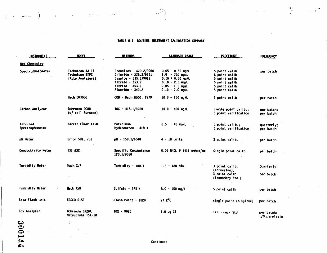
TABLE 8.1 ROUTINE INSTRUMENT CALIBRATION SUMMARY
INSTRUMENT MODEL METHODS STANDARD RANGE PROCEDURE FREQUENCY
Wet Chemistry
Spectrophotometer
Carbon Analyzer
InfraredSpectrophometer
pH Meter
Conductivity Meter
Turbidity Meter
Turbidity Meter
Seta-Flash Unit
Tox Analyzer
COoo •
Technlcon AA IITechnlcon 6TPC(Auto Analyzers)
Hach DR3000
Dohrmann OC80(w/ soil furnace)
Perkin Elmer 1310
Orion 501. 701
YSI 132
Hach X/R
Hach X/R
EROCO 015F
Dohrnunn OX20AMitsubishi TSX-10
Phenol ics - 420.2/9066Chloride - 325.2/9251Cyanide - 335.3/9012Nitrate - 353.2Nitrite - 353.2Fluoride - 340.2
COD - Hach 8000. 1979
TOC - 415.1/9060
PetroleumHydrocarbon - 416.1
pH - 150.1/9040
Specific Conductance120.1/9050
Turbidity - 180.1
Sulfate - 375.4
Flash Point - 1020
TOX - 9020
0.05 - 0.30 mg/L5.0 - 200 mg/L0.10 - 0.50 mg/L0.10 - 2.0 mg/L0.05 - 1.0 mg/L0.10 - 2.0 mg/L
10.0 - 150 mg/L
10.0 - 400 mg/L
0.5 - 40 mg/L
4-10 units
0.01 NKCL • 1413 umhos/cm
1.8 - 160 NTU
5.0 - 150 mg/L
27.2°C
1.0 ug Cl
5 point callb.5, point callb.5 point calib.5 point callb.5 point callb.5 point callb.
5 point calib.
Single point callb. ;5 point verification
5 point callb.;2 point verification
3 point callb.
Single point callb.
3 point callb.(Forma* In*);3 point calfb.(Secondary Std. )
5 point callb.
single point (p-xylene)
Cal. check Std
per batch
per batch
per batch;per batch
quarterly;per batch
per batch
per batch
Quarterly;
per batch
per batch
per batch
per batch;1/8 pyrolysis
Continued
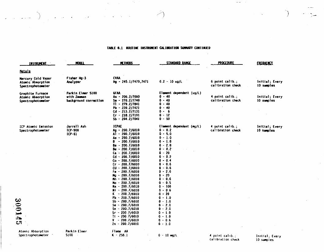
TABLE 8.1 ROUTINE INSTRUMENT CALIBRATION SUMMIT CONTINUED
INSTRUMENT MODEL
Metals
Mercury Cold VaporAtomic AbsorptionSpect rophotometer
Graphite FurnaceAtomic AbsorptionSpect rophotometer
Fisher Hg-3Analyzer
Parkin Elmer 5100with Zeemanbackground correction
METHODS
ICP Atomic EmissionSpect rophotometer
Jarrell AshICP-9001CP-61
GO.oo
Atomic AbsorptionSpectrophotometer
Perktn Elmer5100
CVAAHg - 245.1/7470,7471
GFAAAs - 206.2/7060Se - 270.2/7740Tl - 279.2/7841Pb - 239.2/7421Cd - 213.2/7131Cr - 218.2/7191Sb - 204.2/7041
ICPAEAg - 200A1 - 200As - 200B - 200Ba - 200.Be - 200.Ca - 200.Cd - 200.Co - 200.Cr - 200.CU - 200.Fe - 200.Mg - 200.Mn - 200.Mo - 200.Na - 200.Ni - 200.K - 200.Pb - 200.Sb - 200.Se - 200.Sn - 200.Sr - 200.Ti - 200.V - 200.Zn - 200.
.7/6010
.7/6010
.7/60107/60107/60107/60107/60107/60107/60107/60107/60107/60107/60107/60107/60107/60107/60107/60107/60107/60107/60107/60107/60107/60107/60107/6010
Flame AAK - 258.1
STANDARD RANGE
0.2 - 10 ug/L
Element dependent (ug/L)0 - 400 - 400 - 400 - 400 - 60 - 120 - 50
Element dependent (mg/L)0 - 0.20 - 5.00 - 1.00 - 1.0
2.00.2200.20.40.60.62.0200.60.51000.6201.0
PROCEDURE
6 point caltb.;calibration check
4 point caltb.;calibration check
FREQUENCY
Initial; Every10 samples
Initial; Every10 samples
4 point calib.;calibration check
Initial; Every10 samples
- 1 02.02.01.01.00.61.0
0 - 10 mg/L 4 point calib.;ca)ibrat ion check
Initial, Every10 samples
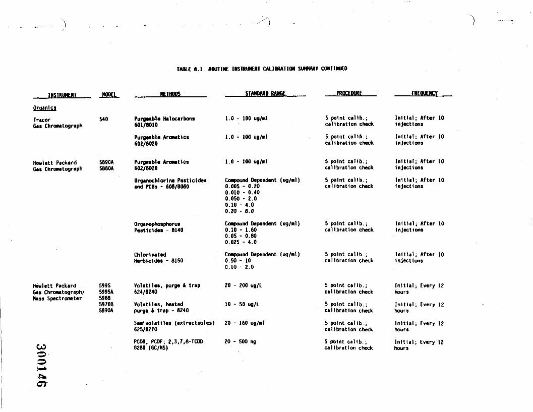
TABLE 6.1 ROUTINE INSTRUMENT CALIBRATION SUMMARY CONTINUED
INSTRUMENT
Organ!cs
TracorGas Chronatograph
540
METHODS STANDARD RANGE
Purgeabla Halocarbons601/6010
Purgeable Aromattcs602/6020
PROCEDURE
1.0 - 100 ug/nl
1.0-100 ug/nl
5 point callb.;calibration check
5 point calib.;calibration check
FREQUENCY
Initial; After 10injections
Initial; After 10injections
Hewlett Packard 5890AGas Chromatograph S880A
Purgeable Aromatic*602/8020
Organochlortne Pesticidesand PCBs - 606/8060
OrganophosphorusPesticides - 8140
ChlorinatedHerbicides - 6150
1.0 - 100 ug/ml
Compound Dependent (ug/ml)0.005 - 0.200.010 - 0.400.050 - 2.00.10 - 4.00.20 - 8.0
Compound Dependent (ug/ml)0.10 - 1.600.05 - 0.800.02S - 4.0
Compound Dependent (ug/ml)0.50 - 100.10 - 2.0
5 point calib.;calibration check
5 point callb.;calibration check
5 point callb.;calibration check
5 point callb.;calibration check
Initial; After 10injections
Initial; After 10injections
Initial; After 10injections
Initial; After 10injections
Hewlett PackardGas ChroMtograph/Mass Spectrometer
59955995A59885970B5890A
Volattles, purge t trap624/8240
Volatile*, heatedpurge It trap - 8240
20 - 200 ug/L
10 - 50 ug/L
CO
SeNlvolatlles (extractables) 20 - 160 ug/ml625/8270
PCDO, PCDF; 2.3.7,8-TCDD 20 - 500 ng8280 (GC/NS)
5 point callb.;calibration check
5 point callb.;calibration check
5 point callb.;calibration check
5 point callb.;calibration check
Initial; Every 12hours
Initial; Every 12hours
Initial; Every 12hours
Initial; Every 12hours
.or
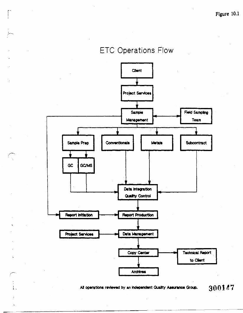
Figure 10.1
ETC Operations Flow
Sample Prep
1GC GC/MS
Client
Project Services
iSample
Management
Conventional*
IMetal*
Data IntegrationQualty Control
Report Initiation [1
Report Production |
| Project Service* |————»j Data Management |
Copy Center
Archive*
Field SamplingTeam
1Subcontract
Technical ReporttoCBent
AB operation* reviewed by an Independent OuaJrty Ateurance Group. 3001 4 7
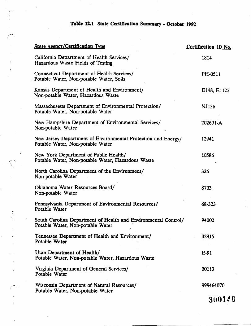
Table 12.1 State Certification Summary • October 1992
State Agency/Certification Type
California Department of Health Services/Hazardous Waste Fields of Testing
Connecticut Department of Health Services/Potable Water, Non-potable Water, Soils
Kansas Department of Health and Environment/Non-potable Water, Hazardous Waste
Massachusetts Department of Environmental Protection/Potable Water, Non-potable Water
New Hampshire Department of Environmental Services/Non-potable Water
New Jersey Department of Environmental Protection and Energy/Potable Water, Non-potable Water
New York Department of Public Health/Potable Water, Non-potable Water, Hazardous Waste
North Carolina Department of the Environment/Non-potable Water
Oklahoma Water Resources Board/Non-potable Water
Pennsylvania Department of Environmental Resources/Potable Water
South Carolina Department of Health and Environmental Control/Potable Water, Non-potable Water
Tennessee Department of Health and Environment/Potable Water
Utah Department of Health/Potable Water, Non-potable Water, Hazardous Waste
Virginia Department of General Services/Potable Water
Wisconsin Department of Natural Resources/Potable Water, Non-potable Water
Certification ID No.
1814
PH-0511
E148, El 122
NJ136
202691-A
12941
10586
326
8703
68-323
94002
02915
E-91
00113
999464070
300148
•
TJT)mgxCD
300119
APPENDIX B
BLANK FIELD FORMS AND LOGS
300!§0r2-ban-761/93
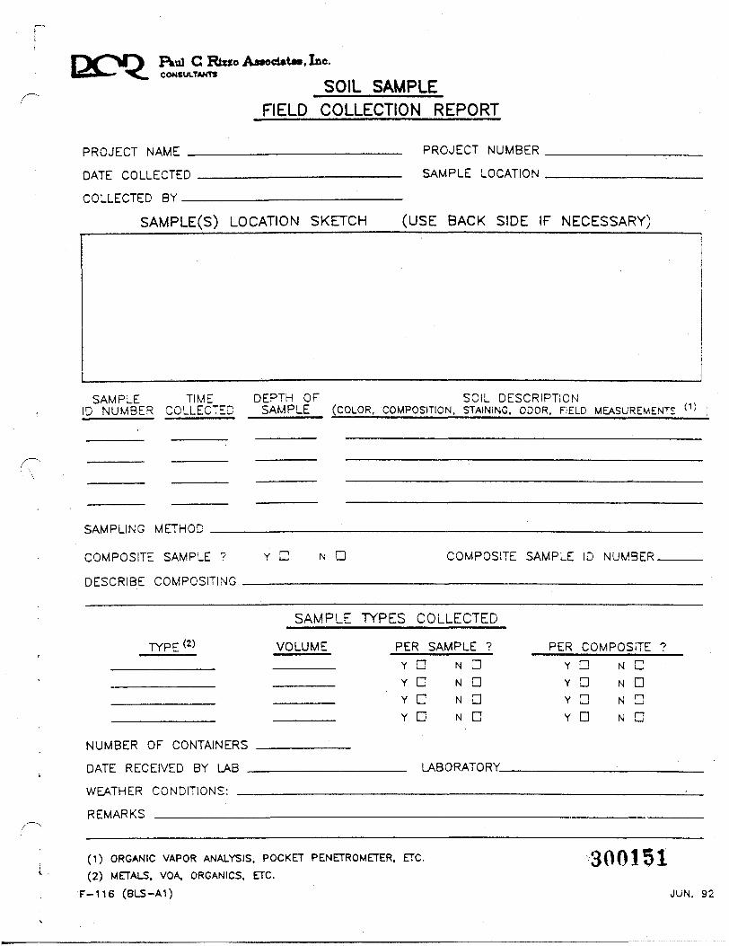
FVul C Rtzzo AModttM, Inc.CONSULTANTS
SOIL SAMPLEFIELD COLLECTION REPORT
PROJECT NAME
DATE COLLECTED
COLLECTED BY _
PROJECT NUMBER
SAMPLE LOCATION
SAMPLE(S) LOCATION SKETCH (USE BACK SIDE IF NECESSARY)
SAMPLE TIMEID NUMBER COLLECTED
DEPTH OF SOIL DESCRIPTIONSAMPLE (COLOR. COMPOSITION. STAINING, ODOR. FIELD MEASUREMENTS
SAMPLING METHOD
COMPOSITE SAMPLE ? N D COMPOSITE SAMPLE ID NUMBER.
SAMPLE TYPES COLLECTED
TYPE(2) VOLUME PER SAMPLE ?
NUMBER <~>F rDNTAINFRS
DATE RFOFIVFD BY 1 AR
WF^THFR rnwnmnwc.
RFMARKR
Y C
Y nY nY D
N nN DN aN a
PER COMPOSITE ?YD N C
YD N aY n N nYD N a
1 ARORATORY
(1) ORGANIC VAPOR ANALYSIS. POCKET PENETROMETER. ETC.
(2) METALS. VOA, ORGANICS. ETC.
F-116 (BLS-A1)
300151JUN. 92
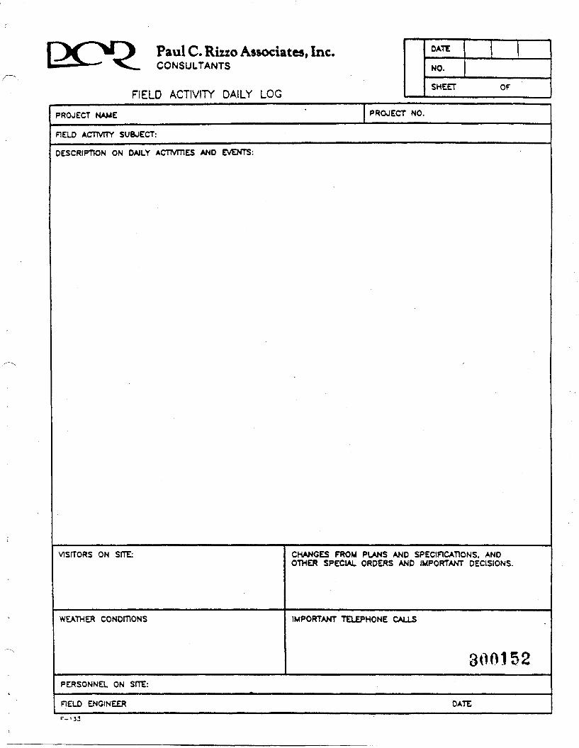
Paul C. Rizzo Associates, Inc.CONSULTANTS
FIELD ACTIVITY DAILY LOG
DATE
NO.
SHEET Or
PROJECT NAME PROJECT NO.
FIELD ACTIVITY SUBJECT:
DESCRIPTION ON DAILY ACTMTiES AND EVENTS:
VISITORS ON SHE: CHANGES FROM PLANS AND SPECIFICATIONS. ANDOTHER SPECIAL ORDERS AND IMPORTANT DECISIONS.
WEATHER CONDITIONS IMPORTANT TELEPHONE CALLS
300152PERSONNEL ON SfTE:
FIELD ENGINEER DATE
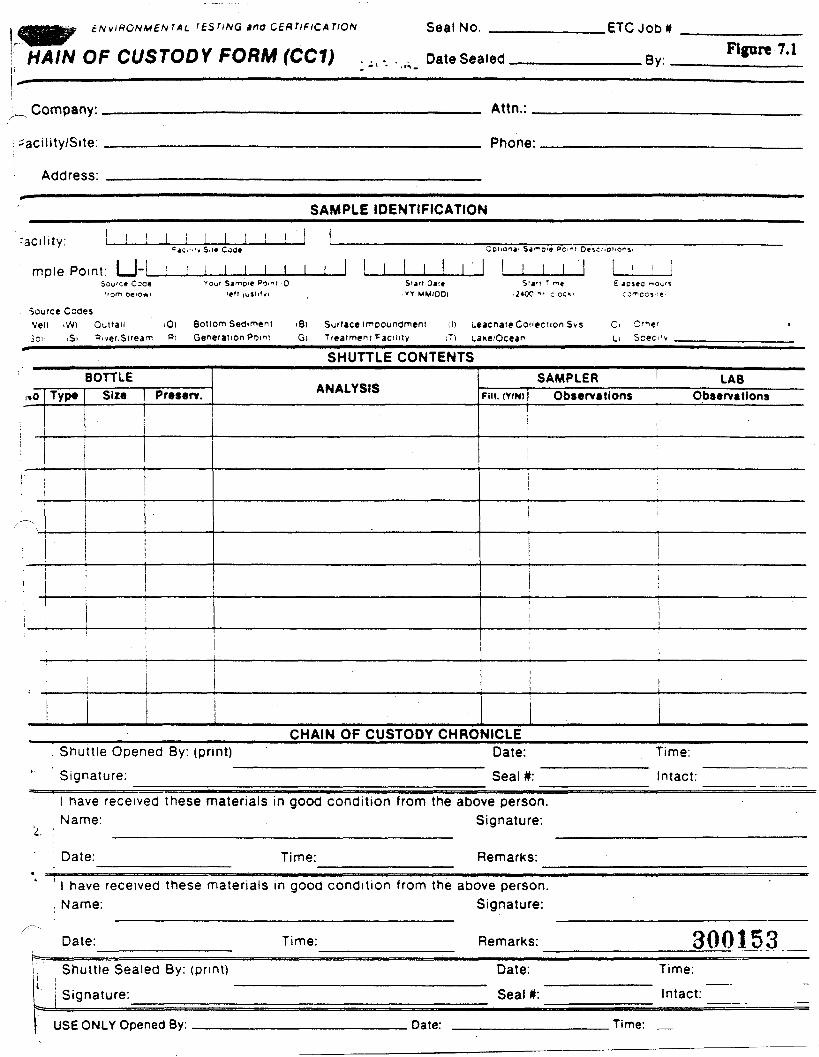
e/MV/HON«£/vr>U r^STiNG ina CERTIFICATION
MAIN OF CUSTODY FORM (CC1)Seal No.
Date Sealed
.ETC Jobn
——— By..Figure 7.1
_ Company:.
• acility/Site:
Address:
Attn.:
Phone:
SAMPLE IDENTIFICATION
• acility: J_I
mple Point: I_rL I I I I lSou'ce Coo« »our Sainoi* Po.ni iO Sun Oat* S;*-! T "i*>r0m o«'0*i i«ll loslityi . W MM/OOl .J«00 •" ;.oc«'
Source CooesVeil iWi Out'ati iO) Bottom Seaiment iB) Surface imoounoment ill Leacnate Collection SysSon 'Si Piver.Sirea^ Pi Generation Point ,QI Treatment Facility ;Ti take/Ocean
£ JD
Ci Ot"e'L> Soec''v
SHUTTLE CONTENTS
nO
-^
: •
Typ«BOTTLE
Size Pr»s*rv.AUAI VCIC
SAMPLER ' LABput. (Y/N) Observations Observations
i !
:iii
1
CHAIN OF CUSTODY CHRONICLEShuttle Opened By: (print)
Signature:Date:Seal *:
Time:
Intact:
I have received these materials in good condition from the above person.Name: Signature:
Date: Time: Remarks:
I have received these materials in good condition from the above person., Name: Signature:
Date: Time:
Shuttle Sealed By: (print)
j Signature:
. IIRPONI V Opened By:
Remarks:
Date:Seal *:
Date:
300153Time:
Intact:
Time:
Ptul C Rizzo AMoeutM, Inc.CONSULTANTS
EQUIPMENT CALIBRATION LOGPROJECT NAME:————————————————:—————————————PROJECT NUMBER: ————————————————————————————DATE:__________________PERFORMED BY:_______
INSTRUMENT TYPE: _______INSTRUMENT MODEL NUMBER:INSTRUMENT SERIAL NUMBER:.
DESCRIPTION OF CALIBRATION PROCEDURE:,
STANDARD pH OR CONCENTRATION INSTRUMENT READING
REMARKS:
300154
F-297
APPENDIX C
O:oCO
r
APPENDIX C
TARGET COMPOUND LIST/TARGET ANALYTE LIST
300156r2-ban-761/93
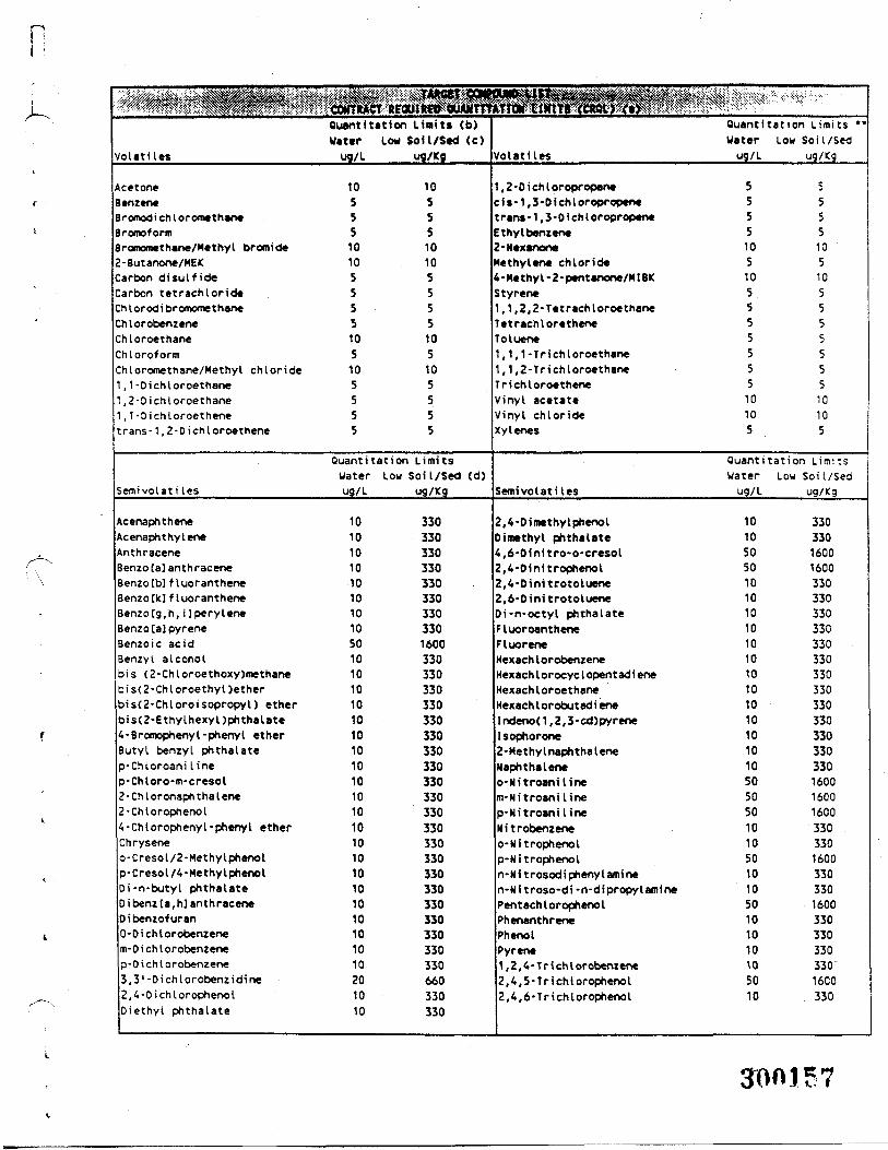
n
Volatile*
AcetoneBenzeneBromodi ch loromethaneBromoformBromomethane/Methyl bromide2-Butanone/MEKCarbon disulfideCarbon tetrachlorideChlorodi bromomethaneChlorobenzeneChloroethaneChloroformChloromethane/Methyl chloride1 , 1-Di chloroethane1 , 2 -Di chloroethane1 , 1-Dichloroethenetrans-1 ,2-Dichloroethene
Semivolati les
AcenaphtheneAcenaphthyleneAnthraceneBenzo [a] anthraceneBenzo [b] f luorantheneBenzo Ckl f 1 uor antheneBenzo [g,h, UperyleneBenzo[a]pyreneBenzole acidBenzyl alcoholbis (2-Chloroethoxy)methaneb i s( 2 -Ch I oroethy I )etherbis(2-Chloroisopropyl) etherbis(2-Ethylhexyl)phthalate4-Bromophenyl-phenyl etherButyl benzyl phthalatep-Chloroani I inep-Chloro-m-cresol2-Chtoronaphthalene2-Chlorophenol4-Chlorophenyl-phenyl etherChryseneo-Cresol/2-Methylphenolp-Cresol/4-MethylphenolDi-n-butyl phthalateD i benz [a , h] ant h raceneOibenzofuran0-Di chl orobenzenem-0 i ch I orobenzenep-0 i ch I orobenzene3,3'-Dichlorobenzidine2,4-OichlorophenolDiethyt phthalate
HMQuant Station Limits (b)WaterU9/L
1055510105555105105555
Low Soil/Sed <c)ug/Kg
1055510105555105105555
Quant Station LimitsWater Low Soil/Sed (d)ug/L
101010101010101050101010101010101010101010101010101010101010201010
ug/Kg
3303303303303303303303301600330330330330330330330330330330330330330330330330330330330330330660330330
Volatiles
, 2 • D i ch I or opr opantc i •- 1 , 3-0 i ch 1 oropropenet ran* - 1 , 3 - 0 i ch I oropropeneEthyl benzene2-HexanooeMethyltnt chloride4-Methyl-2-pentanone/M!BKStyrene,1,2,2-Tetrachloroethane
Tetrachloretheneoluene,1,1-Tri chloroethane,1,2-Tri chloroethane
TrichloroetheneVinyl acetateVinyl chlorideXylenes
Semivolati les
2,4-DimethylphenolDimethyl phthalate4,6-Dinitro*o-cresol2, 4 -Dini trophenol2,4-Dinitrotoluene2,6-DinitrotolueneDi-n-octyl phthalateFluoroantheneFluor eneHexach I orobenzeneHexach I orocyc I opent ad i eneHexach I oroethaneHexach lorobutadi eneIndenod ,2,3-cd)pyreneIsophorone2-MethylnaphthaleneNaphthaleneo-Nitroanilinem-Nitroani linep-Nitroani lineNitrobenzeneo-Ni trophenolp-Ni trophenoln-Nitrosodiphenylaminen-Nitroso-di-n-dipropylaminePentach 1 oropheno IPhenanthrenePhenolPyrene1, 2, 4-Tri chl orobenzene2,4,5-Trichlorophenol2,4,6-Trichlorophenol
fjlllll̂ ^̂ '' 'Ouantitation Limits *•Water Low Soil/Sedug/L ug/Kg
5 55 55 55 510 105 510 105 55 55 55 55 55 55 510 1010 105 5
Quant Station LimitsWater Low Soil/Sed
ug/L ug/Kg
10 33010 33050 160050 160010 33010 33010 33010 33010 33010 33010 33010 33010 33010 33010 33010 33010 33050 160050 160050 160010 33010 33050 160010 33010 33050 160010 33010 33010 33010 330'50 16CO10 330
30015
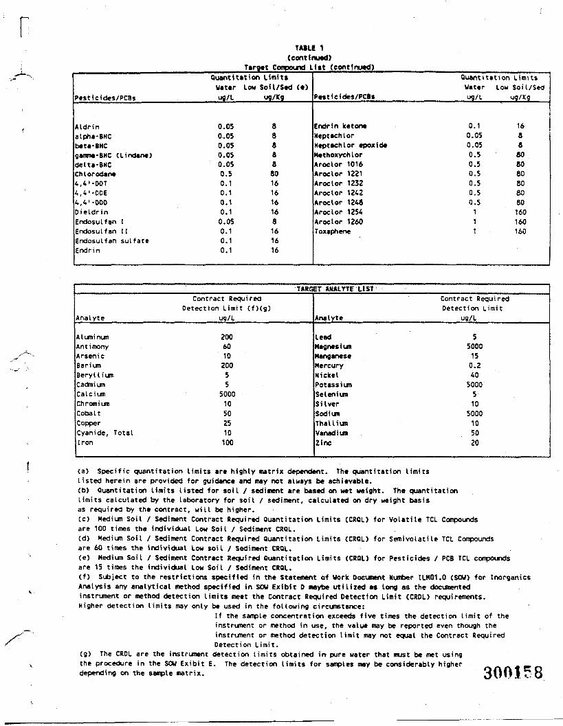
rTAtlC 1
(continued)Target Compound 11tt (continued)
Pesticides/PCBs
Aldrinalpha-BHCbeta-BMCgamma-BHC (Lindane)delta-BHCChlorodane4, 4' -DOT4,4'-OOE4, 4 '-000OietdrinEndosulfan IEndosulfan IIEndosulfan sulfateEndrin
Quant i tat ion LimitsUattr Low Soil/Sed (t)ug/L ug/Kg
0.050.050.050.050.050.50.10.10.10.10.050.10.10.1
8888880161616168161616
Pesticides/PCBs
Endrin ketoneHeptachlorHeptachlor epoxideMethoxychlorA roc I or 1016Aroctor 1221Aroclor 1232Aroctor 1242Aroclor 1248Aroclor 1254Aroclor 1260Toxaphene
Quant i tat ionWater Lowug/L
0.10.050.050.50.50.50.50.50.5111
LimitsSoil/Sedug/Kg
1688808080808080160160160
TARC2T AMAmr LIST
Analyte
AluminumAntimonyArsenicBariumBerylliumCadmiumCalciumChromiumCobaltCopperCyanide, TotalIron
Contract RequiredDetection Limit (f)(g)
ug/L
200601020055
500010502510100
Analyte
LeadMagnesiumManganeseMercuryNickelPotassiumSeleniumSilverSodiumThalliumVanadiumZinc
Contract RequiredDetection Limit
ug/L
55000150.24050005105000105020
(a) Specific quantitat ion limits are highly matrix dependent. The quantisation limitslisted herein are provided for guidance and may not always be achievable.(b) Quantitat ion limits listed for soil / sediment are based on wet weight. The quantitat ionlimits calculated by the laboratory for soil / sediment, calculated on dry weight basisas required by the contract, will be higher.(c) Medium Soil / Sediment Contract Required Quantitat ion Limits (CRQL) for Volatile TCL Compoundsare 100 times the individual Low Soil / Sediment CRQL.(d) Medium Soil / Sediment Contract Required Quantitation Limits (CRQL) for Semivolatile TCL Compoundsare 60 times the individual Low soil / Sediment CRQL.(e) Medium Soil / Sediment Contract Required Quantitation Limits (CRQL) for Pesticides / PCS TCL compoundsare 15 times the individual Low Soil / Sediment CRQL.(f) Subject to the restrictions specified in the Statement of Work Document Number ILM01.0 (SOW) for InorganicsAnalysis any analytical method specified in SOW Exibit 0 maybe utilized as long as the documentedinstrument or method detection limits meet the Contract Required Detection Limit (CRDL) requirements.Higher detection limits may only be used in the following circumstance:
If the sample concentration exceeds five times the detection limit of theinstrument or method in use, the value may be reported even though theinstrument or method detection limit may not equal the Contract RequiredDetection Limit.
(g) The CRDL are the instrument detection limits obtained in pure water that must be met usingthe procedure in the SOW Exibit E. The detection limits for samples may be considerably higher f\/\t\m E ndepending on the sample matrix. 3001 ? 8