Embed Size (px)
Citation preview

i
PART 2
THE AASHTO LRFD SPECIFICATIONS
1.0 INTRODUCTION
1.1 Limit State
1.2. Load Combinations
1.3. Design Vehicle Live Load
1.4. Fatigue Load
1.5. Impact (Dynamic Load Allowance = IM)
1.6. Wind
1.7. Distribution Factor
2.0 STEEL STRUCTURES
2.1 Steel Material
2.2 Fatigue and Fracture Limit State
2.3 Resistance Factor
2.4 Tension Members
2.5 Compression Members
2.6 I-Section Flexural Members
2.7 Cross-Section Proportion Limits
2.8 Constructibility
2.9 Service Limit State (Permanent Deformations)
210 Fatigue and Fracture Limit State
2.11 Strength Limit State
2.12 Flexural Resistance-Composite Sections in Positive Flexure
2.13 Composite Sections in Negative Flexure and Noncomposite Sections
2.14 Shear Resistance
2.15 Shear Connectors
2.16 Transverse Stiffeners
2.17 Bearing Stiffeners
2.18 Longitudinal Stiffeners

2-1
PART 2
THE AASHTO LRFD SPECIFICATIONS
1.0 INTRODUCTION
The AASHTO LRFD Specifications are written based on probabilistic limit state theory
with several load combinations listed. These load combinations correspond to four limit states,
Service, Fatigue, Fracture, Strength and Extreme-Event.
Service limit states are restrictions on stress, deformation and crack width under regular
service conditions. They are intended to allow the bridge to perform acceptably for its service
life.
Fatigue and fracture limit states are restrictions on stress range under regular service
conditions reflecting the number of expected stress range excursions. They are intended to limit
crack growth under repetitive loads to prevent fracture during the design life of the bridge.
Strength limit states are intended to ensure that strength and stability, both local and
global, are provided to resist the statistically significant load combinations that a bridge will
experience in its design life. Extensive distress and structural damage may occur under strength
limit states, but overall structural integrity is expected to be maintained.
Extreme event limit states are intended to ensure the structural survival of a bridge during
a major earthquake, or when collided by a vessel, vehicle or ice flow, or where the foundation is
subject to the scour which would accompany a flood of extreme recurrence, usually considered
to be 500 years. They are considered to be unique occurrences whose return period is
significantly greater than the design life of the bridge.

-2
1.1 Limit State
Definition: A condition beyond which the bridge or component ceases to satisfy the
provisions for which it was designed.
Requirement — rniii RRQ =≤ φγη (LRFD Eq. 1.3.2.1-1)
(a) For loads for which a maximum value of iγ is appropriate:
95.0≥= IRDi ηηηη (LRFD Eq. 1.3.2.1-2)
(b) For loads for which a minimum value of iγ is appropriate:
0.11 ≤= IRDi ηηηη (LRFD Eq. 1.3.2.1-3)
(1) Dη = Ductility factor
≥ 1.05 Strength Limit State; non-ductile components and
connections
= 1.00 Strength Limit State; conventional designs and details
complying with these specifications
And all other Limit States
≥ 0.95 Strength Limit State; additional ductility - enhancing
measures
(2) Rη = Redundancy factor
≥ 1.05 Strength Limit State; non-redundant members
= 1.00 Strength Limit State; conventional levels of redundancy
And all other Limit States
≥ 0.95 Strength Limit State; exceptional levels of redundancy
(3) Iη = Operational Importance

-3
≥ 1.05 Strength Limit State; important bridges (“critical” or
“essential” bridges with earthquakes 475-year and 2500-
year return periods, respectively)
= 1.00 Strength Limit State; typical bridges
And all other Limit States
≥ 0.95 Strength Limit State; relatively less important bridges
Example: Major Bridge. Multi-girder Steel. (redundant member)
Fatigue η = (1.0)(1.0)(1.0) = 1.0
Strength η = (1.0)(1.0)(1.05) = 1.05
Others η = (1.0)(1.0)(1.0) = 1.00
Minor Bridge.
Fatigue η = (1.0)(1.0)(1.0) = 1.00
Strength η = (1.0)(1.0)(0.95) = 0.95
Others η = (1.0)(1.0)(1.0) = 1.0
1.2. Load Combinations
The permanent and transient loads and forces listed in Section 1.6 shall be considered in
the various load combinations. The complete list is in Tables 1-1 and 1-2 (LRFD Table 3.4.1-1
& Table 3.4.1-2).
iii qQ ∑= γη (LRFD Eq. 3.4.1-1)
(1) Strength I - Normal vehicle, no wind
... L 1.75 ++DPγ Pγ - DC = 1.25 - 0.9
DW = 1.5 - 0.85
(2) Strength II - Permit vehicle, no wind
... L1.35 ++DPγ
(3) Strength III - No live load, max. wind
... 1.4WS ++DPγ

-4
(4) Strength IV - Dead load only (for large bridge)
Pγ D + ... Pγ - DC = 1.5 - 0.9
(5) Strength V - Normal vehicle with 55mph Wind
DPγ + 1.35 L + 0.4 WS + 1.0 WL + ...
(6) Extreme I - Earthquake
DPγ + LEQγ + EQ
(7) Extreme II - Ice load, collision and certain hydraulic events
DPγ + 0.5 L + Max. (IC, CT, CV) + ...
(8) Service I - Normal operation with 55mph Wind
D + L + 0.3 WS + 1.0WL + ...
(9) Service II - Overload event, intended to control yielding of steel structures and
slip of slip-critical connections due to vehicular live load.
D + 1.3 L + ...
(10) Service III - Tension in prestressed concrete superstructure
D + 0.8L + . . .
(11) Service IV - Tension is prestressed concrete substructure
D + 0.7 WS + …
(12) Fatigue - Fatigue event, stress range of a single design truck
0.75 L
So:
Superstructure - Check Strength I, II, Service I, II, (III,) Fatigue.
For large bridges, also check Strength III, IV, V, Extreme
Substructure - Check Strength I, II, III, IV, V, Extreme, Service I, II (,III). (Add
WA + FR to all the conditions.)
-5
TABLE 1-1 AASHTO LOAD COMBINATION TABLE &
TABLE 1-2 AASHTO LOAD FACTORS FOR PERMANENT LOADS TABLE
Load Combination Use One of These at a Time
Limit State
DC/DD DW/EH EV/ES
EL
LL/IM CE/BR PL/LS
WA WS WL FR TU CR SH
TG SE
EQ IC CT CV
STRENGTH-I (unless noted) γP 1.75 1.00 - - 1.00 0.50/1.20 γTG γSE - - - -
STRENGTH-II γP 1.35 1.00 - - 1.00 0.50/1.20 γTG γSE - - - - STRENGTH-III γP - 1.00 1.40 - 1.00 0.50/1.20 γTG γSE - - - - STRENGTH-IV γP - 1.00 - 1.0 1.00 0.50/1.20 γTG γSE - - - -
STRENGTH-V γP 1.35 1.00 0.40 1.0 1.00 0.50/1.20 γTG γSE - - - - EXTREME EVENT-I γP γEQ 1.00 - - 1.00 - - - 1.00 - - -
EXTREME EVENT-II γP 0.50 1.00 - - 1.00 - - - - 1.00 1.00 1.00
SERVICE-I 1.00 1.00 1.00 0.30 1.0 1.00 1.00/1.20 γTG γSE - - - - SERVICE-II 1.00 1.30 1.00 - - 1.00 1.00/1.20 - - - - - - SERVICE-III 1.00 0.80 1.00 - - 1.00 1.00/1.20 γTG γSE - - - - SERVICE-IV 1.00 - 1.00 0.70 - 1.00 1.00/1.20 - 1.0 - - - - FATIGUE-LL, IM & CE ONLY - 0.75 - - - - - - - - - - -
(AASHTO LRFD TABLE 3.4.1-2 – Load Factors for Permanent Loads, γP)
Load Factor Type of Load Maximum Minimum
DC: Component and Attachments DC: Strength IV only
1.25 1.5
0.90 0.9
DD: Downdrag Piles, α Tomlinson Method Piles, β Tomlinson Method Drilled Shafts, O’Neill and Reese(1999) Method
1.4 1.05 1.25
0.25 0.30 0.35
DW: Wearing Surfaces and Utilities 1.50 0.65 EH: Horizontal Earth Pressure • Active 1.50 0.90 • At-Rest • AEP for anchored walls
1.35 1.35
0.90 N/A
EL: Locked-in Erection Stresses 1.00 1.00 EV: Vertical Earth Pressure • Overall Stability 1.00 N/A • Retaining Structure(Walls and Abutments) 1.35 1.00 • Rigid Buried Structure 1.30 0.90 • Rigid Frames 1.35 0.90 • Flexible Buried Structures other than Metal Box Culverts 1.95 0.90 • Flexible Metal Box Culverts 1.50 0.90 ES: Earth Surcharge 1.50 0.75

-6
FIGURE 1-1 LRFD DESIGN VEHICULAR LIVE LOAD, HL-93

-7
1.3. Design Vehicle Live Load (LRFD Art. 3.6.1.2)
The vehicular live loading for LRFD is designated HL-93 (Figure 2-1), which consists of
a combination of the:
(1) Design Truck + Design Lane
(2) Design Tandem + Design Lane
! For M - or Reactions at interior piers, two 90% Design Trucks spaced at least 50ft
+ 90% Design Lane
Multiple presence factors are not to be applied to the fatigue limit state for which one
design truck is used, regardless of the number of design lanes. Thus, the factor 1.20 must be
removed from the single lane distribution factors when they are used to investigate fatigue.
Number of Loaded
Lanes
Multiple Presence
Factors, m
1 1.20
2 1.00
3 0.85
>3 0.65
FIGURE 1-2 AASHTO LRFD MULTIPLE PRESENCE FACTORS

-8
1.4. Fatigue Load
Design truck only with constant 30' between 32-kip axles. (LRFD Art. 3.6.1.4)
ADTTsingle-lane = p x ADTT
where p = 1.0 for one-lane bridge
= 0.85 for two-lane bridge
= 0.80 for three-lane or more bridge
Class of Highway ADTT/ADT
Rural Interstate 0.2
Urban Interstate 0.15
Other Rural 0.15
Other Urban 0.10
Example: Rural Interstate 4-lane bridge (Major)
ADTTsingle-lane = (0.8)(0.2)ADT = 0.16 ADT
Rural 2-lane bridge (Minor)
ADTTsingle-lane = (0.85)(0.15)ADT = 0.1275 ADT
(Max ADT = 20,000 vehicles/lane/day)
1.5. Impact (Dynamic Load Allowance = IM) (LRFD Art. 3.6.2)
Deck Joints — All Limit States IM = 75%
All other components, Fatigue and Fracture Limit State IM = 15%
All other components, All other Limit States IM = 33%
Applied to design truck or tandem only; not to be applied to pedestrian loads or to the
design lane load.

-9
1.6. Wind (LRFD Art. 3.8)
(1) On structure: WS
Windward Leeward
(a) Trusses, Columns 0.05 ksf 0.025 ksf * H
and Arches (0.30 klf min.) (0.15 klf min.) VD2 / 10,000
(b) Beams 0.05 ksf NA
(0.30 klf min.)
(c) Large Flat Surfaces 0.04 ksf NA
A multi-girder bridge. 55 mph design Wind. d = 5′
p = 0.05 x 5 x 552 / 10,000 = 0.075625 klf
= 0.30 x 552 / 10,000 = 0.09075 klf ← govern
(2) On Vehicles = WL (100 lb/ft acting 6 ft above the roadway, based on 55 mph)
1.7. Distribution Factor (LRFD Art. 4.6.2.2)
(Steel I-Beams, Prestress Concrete, Concrete T-Beam on Concrete deck)
Definition: The AASHTO Specs permit a simplified method by modeling a longitudinal
girder or a strip of unit width for obtaining longitudinal moments and shears due
to live load. This beam is isolated from the rest of the structure and treated as a
one-dimensional beam. This isolated beam is subjected to loads comprising one
axle of the design vehicle multiplied by a load fraction “g.” This “g” is defined as
Axle Load Distribution Factor in LRFD Specs., which is different from the Wheel
Load Distribution Factor defined in the AASHTO Specs.

-10
A. Moment -
(1) Interior — (Table 1-3 & AASHTO LRFD Table 4.6.2.2.2b-1)
(a) One lane
1.0
3
3.04.0
interior 121406.0 ⎟⎟
⎠
⎞⎜⎜⎝
⎛⎟⎠⎞
⎜⎝⎛
⎟⎠⎞
⎜⎝⎛+=
s
g
Ltk
LSSg
(b) Two or more lanes
1.0
3
2.06.0
interior 125.975.0 ⎟⎟
⎠
⎞⎜⎜⎝
⎛⎟⎠⎞
⎜⎝⎛
⎟⎠⎞
⎜⎝⎛+=
s
g
Ltk
LSSg
6163 ′≤≤′′−′ S , 215.4 ′′≤≤′′ st , 02402 ′≤≤′ L , 4≥bN
(2) Exterior — (Table 1-4 & AASHTO LRFD Table 4.6.2.2.2d-1)
(a) One lane Use level rule.
(b) Two or more lanes,
gexterior = e × ginterior
e = 0.77 + de / 9.1 –1′ – 0″ ≤ de ≤ 5′ – 6″
FIGURE 1-3 ILLUSTRATION OF THE G-VALUE METHOD

-11
TABLE 1-3 AASHTO TABLE FOR THE MOMENT DISTRIBUTION FACTOR OF THE
INTERIOR BEAMS (AASHTO LRFD Table 4.6.2.2.2b-1 – Distribution of Live loads Per Lane for Moment in interior Beams)
Type of Beams Applicable Cross-Section from Table – 4.6.2.2.1-1
Distribution Factors Range of Applicability
Wood Deck on Wood or Steel Beams
a, l See Table 4.6.2.2.2a-1
Concrete Deck on Wood Beams
l Once Design Land Loaded: S/12.0 Two or More Design Lanes Loaded: S/10.0
S ≤ 6.0
One Design Lane Loaded: 1.0
3
3.04.0
0.121406.0 ⎟⎟
⎠
⎞⎜⎜⎝
⎛⎟⎠⎞
⎜⎝⎛
⎟⎠⎞
⎜⎝⎛+
s
g
LtK
LSS
Two or More Design Lanes Loaded: 1.0
3
2.06.0
0.125.9075.0 ⎟⎟
⎠
⎞⎜⎜⎝
⎛⎟⎠⎞
⎜⎝⎛
⎟⎠⎞
⎜⎝⎛+
s
g
LtK
LSS
3.5 ≤ S ≤ 16.0 4.5 ≤ ts ≤ 12.0 20 ≤ L ≤ 240 Nb ≥ 4 10,000 ≤Kg ≤ 7,000,000
Concrete Deck, Filled Grid, Partially Filled Grid or Unfilled Grid Deck Composite with Reinforced Concrete Slab on Steel or Concrete Beams; Concrete T-Beams, T- and Double T-Sections
a, e, k and also i, j
if sufficiently connected to act as a unit
Use lesser of the values obtained from the equation above with Nb = 3 or the lever rule.
Nb = 3
One Design Lane Loaded: 45.035.0 11
6.375.1 ⎟⎟
⎠
⎞⎜⎜⎝
⎛⎟⎠⎞
⎜⎝⎛
⎟⎠⎞
⎜⎝⎛ +
cNLS
Cast-in-Place Concrete Multicell Box
d
Two or More Design Lanes Loaded: 25.03.0
18.5
13⎟⎠⎞
⎜⎝⎛
⎟⎠⎞
⎜⎝⎛
⎟⎟⎠
⎞⎜⎜⎝
⎛L
SNc
7.0 ≤ S ≤ 13.0 60 ≤ L ≤ 240 Nc ≥ 3 If Nc > 8 use Nc = 8
One Design Lane Loaded: 25.0
2
35.0
0.120.3⎟⎠⎞
⎜⎝⎛
⎟⎠⎞
⎜⎝⎛
LSdS
Two ore More Design Lanes Loaded: 125.0
2
6.0
0.123.6⎟⎠⎞
⎜⎝⎛
⎟⎠⎞
⎜⎝⎛
LSdS
6.0 ≤ S ≤ 18.0 20 ≤ L ≤ 140 18 ≤ d ≤ 65 Nb ≥ 3
Concrete Deck on Concrete Spread Box Beams
b, c
Use Lever Rule S > 18.0

2-12
TABLE 1-3 AASHTO TABLE FOR THE MOMENT DISTRIBUTION FACTOR OF THE
INTERIOR BEAMS
(Continued)
Type of Beams Applicable Cross-Section from Table – 4.6.2.2.1-1
Distribution Factors Range of Applicability
f
g if sufficiently
connected to act as a unit
One Design Lane Loaded: 25.05.0
3.33⎟⎠⎞
⎜⎝⎛
⎟⎠⎞
⎜⎝⎛
JI
Lbk
where: k = 2.5 (Nb)-0.2 ≥ 1.5 Two or More Design Lanes Loaded:
06.02.06.0
0.12305⎟⎠⎞
⎜⎝⎛
⎟⎠⎞
⎜⎝⎛
⎟⎠⎞
⎜⎝⎛
JI
Lbbk
35 ≤ b ≤ 60 20 ≤ L ≤ 120 5 ≤ Nb ≤ 20
h
Concrete Beams Used in Multi-Beam Decks
g, i, j if connected
only enough to prevent relative
vertical displacement at
the interface
Regardless of Number of Loaded Lanes: S/D where: C = K (W/L) D = 11.5 – NL +1.4 NL (1 – 0.2C )2 when C ≤ 5 D = 11.5 – NL when C > 5
( )J
IK μ+=
1
for preliminary design, the following value of K may be used:
Beam Type K Nonvoided rectangular beams 0.7 Rectangular beams with circular voids: 0.8 Box section beams 1.0 Channel beams 2.2 T-Beam 2.0 Double T-Beam 2.0
Skew≤ 45° NL ≤ 6
One Design Lane Loaded: S/7.5 if tg < 4.0 IN S/10.0 if tg ≥ 4.0 IN
S ≤ 6.0 FT Open Steel Gird Deck on Steel Beams
a
Two or More Design Lanes Loaded: S/8.0 if tg < 4.0 IN S/10.0 if tg ≥ 4.0 IN
S ≤ 10.5 FT
Concrete deck on Multiple Steel Box Girders
b, c Regardless of Number of Loaded Lanes:
Lb
L
NNN 425.085.005.0 ++
5.15.0 ≤≤b
L
NN

2-13
TABLE 1-4 AASHTO TABLE FOR THE MOMENT DISTRIBUTION FACTOR OF THE
EXTERIOR BEAMS (AASHTO LRFD Table 4.6.2.2.2d-1)
Type of Superstructure
Applicable Cross-Section from Table
4.6.2.2.1-1
One Design Lane
Loaded
Two or More Design Lanes
Loaded
Range of Applicability
Wood Deck on Wood or Steel
Beams
a, l Lever Rule Lever Rule N/A
Concrete Deck on Wood
l Lever Rule Lever Rule N/A
g = e ginterior
1.977.0 ede +=
-1.0 ≤ de ≤ 5.5 Concrete Deck, Filled Grid,
Partially Filled Grid, or Unfilled
Grid Deck Composite with
Reinforced Concrete Slab on Steel or Concrete Beams; Concrete T-Beams, T and
Double T sections
a, e, k and also i, j
if sufficiently connected to act as a
unit
Lever Rule
Use lesser of the values obtained
from the equation above with Nb = 3 or the lever rule.
Nb = 3
14eWg =
14eWg =
Cast-in-Place Concrete Multi Cell
Box
d
Or the provisions for a whole-width design specified in Article
4.6.2.2.1
We ≤ S
g = e ginterior
5.2897.0 ede +=
0 ≤ de ≤ 4.5 6.0 < S ≤ 18.0
Concrete Deck on Concrete Spread
Box Beams
b, c Lever Rule
Use Lever Rule S > 18.0 Concrete Box
Beams Used in Multi-Beam Decks
f, g Lever Rule g = e ginterior
2504.1 ede +=
-1.0 ≤ de ≤ 2.0
h Concrete Beams other than Box Beams Used in
Multi-Beam Decks
i, j if connected only enough to prevent relative vertical
displacement at the interface
Lever Rule Lever Rule N/A
Open Steel Gird Deck on Steel
Beams
a Lever Rule Lever Rule N/A
Concrete Deck on Multiple Steel Box
Girders
b, c As specified in Table 4.6.2.2.2b-1

-14
(3) Reduction on skew supports. (Table 1-5 & AASHTO LRFD Table 4.6.2.2.2e-1)
R = 1 – c1 (tan 2)1.5
5.025.0
31 1225.0 ⎟
⎠⎞
⎜⎝⎛
⎟⎟⎠
⎞⎜⎜⎝
⎛=
LS
Ltk
cs
g
if 2 < 30o then c1 = 0.0
2 > 60o use 2 = 60o
30º ≤ θ ≤ 60º, 3.5′≤ S ≤ 16.0′, 20 ′≤ L ≤ 240′, Nb ≥ 4
TABLE 1-5 AASHTO TABLE FOR THE MOMENT DISTRIBUTION FACTOR ON
SKEWED SUPPORTS
(AASHTO LRFD Table 4.6.2.2.2e-1 – Reduction of Load Distribution Factors for Moment in Longitudinal
Beams on Skewed Supports)
Type of Superstructure
Applicable Cross-Section from Table
4.6.2.2.1-1
Any Number of Design Lanes Loaded
Range of Applicability
a, e, k Concrete Deck, Filled Grid, Partially Filled
Grid, or Unfilled Grid Deck Composite with Reinforced Concrete
Slab on Steel or Concrete Beams;
Concrete T-Beams, T or Double T Section
i, j if sufficiently
connected to act as a unit
1 – c1(tan θ)1.5
5.025.0
31 0.1225.0 ⎟
⎠⎞
⎜⎝⎛
⎟⎟⎠
⎞⎜⎜⎝
⎛=
LS
LtK
cs
g
If θ < 30º then c1 = 0.0 If θ > 60º use θ = 60º
30º ≤ θ ≤ 60º 3.5 ≤ S ≤ 16.0 20 ≤ L ≤ 240
Nb ≥ 4
Concrete Deck on concrete Spread Box Beams, Cast-in-Place
Multicell Box Concrete Beams, and
Double T Sections used in Multi-Beam
Decks
b, c, d,f, g 1.05 – 0.25 tan θ ≤ 1.0 if θ > 60º use θ = 60º
0 ≤ θ ≤ 60º

-15
FIGURE 1-4 EXAMPLE FOR THE CALCULATION OF MOMENT DISTRIBUTION
FACTORS
Component A D Ad Ad2 Io I
Top Flange ¾˝ × 12˝ 9.00 18.38 165.4 3,040 0.42 3,040 Web 7/16˝ × 16˝ 15.75 1,701 1,701 Bottom Flange 7/8˝ × 16˝ 14.00 -18.44 -258.2 4,760 0.89 4,761 38.75 -92.8 9,502
( )
4in.280,92228.9239.2 −
==−
NAI
39.275.38
8.92−
−=sd in.
dTOP OF STEEL = 18.75 – 23.9 = 21.14 in. dBOT OF STEEL = 18.88 – 2.39 = 16.49 in.
STOP OF STEEL = 14.21
280,9 = 439.0 in.3 SBOT OF STEEL =
49.16280,9
= 562.8 in.3
39.2675.014.210.220.8
=−++=ge in. n = 8
( ) ( )( ) 134,29039.2675.38280,98 22 =+=+= gg AeInK in.4
484.01214
06.01.0
3
3.04.0
interior =⎟⎟⎠
⎞⎜⎜⎝
⎛⎟⎠⎞
⎜⎝⎛
⎟⎠⎞
⎜⎝⎛+=
s
g
Ltk
LSSg lanes
(for this case two lane loaded govens where g interior = 0.698 lanes Exterior Girder – Strength Limit State
700.00.100.7
==DF (use the level rule for one lane loaded)
Multiple presence factor m = 1.2 (Table 3.6.1.1.2-1)
1.2 (0.700) = 0.840 lanes

-16
B. Shear -
(1) Interior — (Table 1-6 & AASHTO LRFD Table 4.6.2.2.3a-1)
(a) One lane ginterior = 0.36 + S/25
(b) Two or more lanes, ginterior = 0.2 + S/12 – (S/35)2.0
3′-5″≤ S ≤ 16′-0″, 20′ ≤ L ≤ 240′, 4.5″≤ ts ≤ 12.0″, Nb ≥ 4
(2) Exterior — (Table 1-7 & AASHTO LRFD Table 4.6.2.2.3b-1)
(a) One lane. Use level rule.
(b) Two or more lanes gexterior = e Η ginterior
e = 0.6 + de / 10 -1.0′ ≤ de ≤5′-6″
(3) Correction on the obtuse corner —
(Table 1-8 & AASHTO LRFD Table 4.6.2.2.3c-1)
θtan122.013.0
3
⎟⎟⎠
⎞⎜⎜⎝
⎛+=
g
s
kLtg
0º ≤ θ ≤ 60º, 3′-5″ ≤ S ≤ 16′-0″, 20′ ≤ L ≤ 240′, Nb ≥ 4

2-17
TABLE 1-6 AASHTO TABLE FOR THE SHEAR DISTRIBUTION FACTOR OF THE
INTERIOR BEAMS (AASHTO LRFD Table 4.6.2.2.3a-1 – Distribution of Live Load Per Lane for Shear in Interior Beams)
Type of Superstructure
Applicable Cross-Section from
Table 4.6.2.2.1-1
One Design lane Loaded
Two or More Design Lanes Loaded
Range of Applicability
Wood Deck on Wood or Steel Beams
a, l See Table 4.6.2.2.2a-1
Concrete Deck on Wood Beams
l Lever Rule Lever Rule N/A
0.2535.0 S
+ 0.2
3122.0 ⎟
⎠⎞
⎜⎝⎛−+
SS
3.5 ≤ S ≤ 16.0 20 ≤ L ≤ 240 4.5 ≤ ts ≤ 12.0 10,000 ≤ Kg ≤ 7,000,000 Nb ≥ 4
Concrete Deck, filled Grid, Partially Filled Grid, or Unfilled Grid Deck Composite with Reinforced Concrete Slab on Steel or Concrete Beams; Concrete T-Beams, T- and Double T-Sections
a, e, k and also i, j
if sufficiently connected to act as
a unit Lever Rule Lever Rule Nb = 3
Cast-in-Place Concrete Multicell Box
d 1.06.0
0.125.9⎟⎠⎞
⎜⎝⎛
⎟⎠⎞
⎜⎝⎛
LdS
1.06.0
0.123.7⎟⎠⎞
⎜⎝⎛
⎟⎠⎞
⎜⎝⎛
LdS
6.0 ≤ S ≤ 13.0 20 ≤ L ≤ 240 35 ≤ ts ≤ 110 Nc ≥ 3
b, c 1.06.0
0.1210⎟⎠⎞
⎜⎝⎛
⎟⎠⎞
⎜⎝⎛
LdS 1.08.0
0.124.7⎟⎠⎞
⎜⎝⎛
⎟⎠⎞
⎜⎝⎛
LdS
6.0 ≤ S ≤ 18.0 20 ≤ L ≤ 140 18 ≤ d ≤ 65 Nb ≥ 3
Concrete Deck on Concrete Spread Box Beams
Lever Rule Lever Rule S > 18.0 Concrete Box Beams Used in Multi-Beam Decks
f, g 05.015.0
130⎟⎠⎞
⎜⎝⎛
⎟⎠⎞
⎜⎝⎛
JI
Lb
⎟⎠⎞
⎜⎝⎛
⎟⎠⎞
⎜⎝⎛
⎟⎠⎞
⎜⎝⎛
⎟⎠⎞
⎜⎝⎛
480.12156
05.01.04.0 bJI
Lbb
0.148
>b
35 ≤ b ≤ 60 20 ≤ L ≤ 120 5 ≤ Nb ≤ 20 25,000 ≤ J ≤ 610,000 40,000 ≤ I ≤ 610,000
h Concrete Beams Other Than Box Beams Used in Multi-Beam Decks
i, j if connected only enough to prevent relative vertical
displacement at the interface
Lever Rule Lever Rule N/A
Open Steel Grid Deck on Steel Beams
a Lever Rule Lever Rule N/A
Concrete Deck on Multiple Steel Box Beams
b, c As specified in Table 4.6.2.2.2b-1

2-18
TABLE 1-7 AASHTO TABLE FOR THE SHEAR DISTRIBUTION FACTOR OF THE
EXTERIOR BEAMS (AASHTO LRFD Table 4.6.2.2.3b-1 – Distribution of Live Load Per Lane for Shear in Exterior Beams)
Type of Superstructure Applicable Cross-Section from
Table 4.6.2.2.1-1
One Design Lane Loaded
Two or more Design Lanes Loaded
Range of Applicability
Wood Deck on Wood or Steel Beams
a, l Lever Rule Lever Rule N/A
Concrete Deck on Wood Beams
l Lever Rule Lever Rule N/A
g = e ginterior
10
6.0 ede +=
-1.0 ≤ de ≤5.5 Concrete Deck, Filled Grid, Partially Filled Grid, or Unfilled Grid Deck Composite with Reinforced Concrete Slab on Steel or Concrete Beams; Concrete T-Beams, T- and Double T-Beams
a, e, k and also i, j
if sufficiently connected to act
as a unit
Lever Rule
Lever Rule Nb = 3
Lever Rule g = e ginterior
5.12
64.0 ede +=
Case-in-Place Concrete Multicell Box
d
Or the provisions for a whole-width design specified in Article 4.6.2.2.1
-2.0 ≤ de ≤ 5.0
g = e ginterior
10
8.0 ede +=
0 ≤ de ≤ 4.5 Concrete Deck on Concrete Spread Box Beams
b, c Lever Rule
Lever Rule S > 18.0 Concrete Box Beams Used in Multi-Beam Decks
f, g g = e ginterior 0.1
2025.1 ≥+= ede
g = e ginterior
0.1/48 ≤b
0.140
0.2121
5.0
≥⎟⎟⎟⎟
⎠
⎞
⎜⎜⎜⎜
⎝
⎛ −++=
bde
e
de ≤2.0 35<b<60
h Concrete Beams Other Than Box Beams Used in Multi-Beam Decks
i, j if connected only enough to prevent relative vertical displacement at
the interface
Lever Rule Lever Rule N/A
Open Steel Grid Deck on Steel Beams
a Lever Rule Lever Rule N/A
Concrete Deck on Multiple Steel Box Beams
b, c As specified in Table 4.6.2.2.2b-1
-19
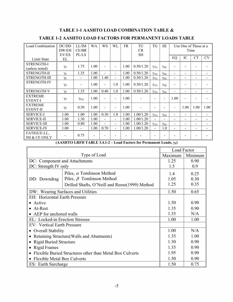
TABLE 1-8 AASHTO TABLE FOR THE DISTRIBUTION CORRECTION FACTOR
FOR SUPPORT SHEAR OF THE OBTUSE CORNER (AASHTO LRFD Table 4.6.2.2.3c-1 – Correction Factors for Load Distribution Factors for Support Shear of
the Obtuse Corner)
Type of Superstructure Applicable Cross-Section
from Table 4.6.2.2.1-1
Correction Factor Range of Applicability
a, e, k Concrete Deck, Filled Grid, Partially Filled Grid, or Unfilled Grid Deck Composite with Reinforced Concrete Slab on Steel or Concrete Beams; Concrete T-Beams, T- and Double T Section
i, j if sufficiently connected to act as a unit
θtan0.1220.00.13.0
3
⎟⎟⎠
⎞⎜⎜⎝
⎛+
g
s
KLt
0º ≤ θ ≤ 60º 3.5 ≤ S ≤ 16.0 20 ≤ L ≤ 240 Nb ≥ 4
Cast-in-Place Concrete Multicell Box
d θtan
700.1225.00.1 ⎥⎦
⎤⎢⎣⎡ ++
dL
0º ≤ θ ≤ 60º 6.0 ≤ S ≤ 13.0 20 ≤ L ≤ 240 35 ≤ d ≤ 110 Nc ≥ 3
Concrete Deck on Spread Concrete Box Beams
b, c
θtan6
0.120.1S
Ld
+
0º ≤ θ ≤ 60º 6.0 ≤ S ≤ 11.5 20 ≤ L ≤ 140 18 ≤ d ≤ 65 Nb ≥ 3
Concrete Box Beams Used in Multi-Beam Decks
f, g θtan
900.120.1dL
+ 0º ≤ θ ≤ 60º 20 ≤ L ≤ 120 17 ≤ d ≤ 60 35 ≤ b ≤ 60 5 ≤ Nb ≤ 20

2-1
2.0 STEEL STRUCTURES
2.1 Steel Material (LRFD Art. 6.4)
AASHTO Equiv. ASTM M270 Grade 36 A709 Grade 36 Structural 50 50 Steel 50W 50W 70W 70W 100/100W 100/100W Pins, Rollers M169 A108 Grade 36 Rockers M102 A668 Class C 33 Class D 37.5 Class F 50
Class G 50 Bolts A307 M164 A325 M253 A490 Nuts M291 A563 Washers M239 F436 Studs M169 A108 Cap A109 Cast Steel M192 A486 M103 A27 M163 A743 Ductile Iron A536 Ferritic Malleable A47 Grade 35018 Iron Castings Cast Iron M105 Class 30 A48 Casting Stainless A176 Steel A240 A276 A666 Wires A510 (Cables) A641(Zinc-Coated) A99 (Epoxy-Coated) A603(Zinc-Coated Wire Rope) A586(Zinc-Coated Parallel and Helical )

-2
.2 Fatigue and Fracture Limit State (LRFD Art. 6.6)
The fatigue provisions of the Steel Structures Section of the AASHTO LRFD
Specification for Highway Bridge Design combine aspects of both the AASHTO Standard
Specification for Highway Bridges (AASHTO 1996) and the Guide Specification for Fatigue
Design of Steel Bridges (AASHTO 1989). These provisions are based upon two principles of
fatigue of welded steel details:
If all of the stress ranges that a welded steel detail experiences in its lifetime are less than the
constant-amplitude fatigue threshold (i.e., the maximum stress range is less than the
threshold), the detail will not experience fatigue crack growth; otherwise
the fatigue life of the detail can be estimated considering an effective (weighted average of
sorts) stress range, which represents all of the varying magnitudes of stress range
experienced by the detail during its lifetime.
These two principles result in two branches in the flow of fatigue design, infinite life design and
finite life design.
Fatigue details for bridges with higher truck traffic volumes are designed for infinite life.
This practice is carried over from both the Standard Specifications and the Guide Specifications.
Bridges with lower truck traffic volumes are designed for the fatigue life required by the
estimated site-specific traffic volumes projected for their lifetimes.
( ) ( )nFf Δ≤Δγ (LRFD Eq. 6.6.1.2.2-1)
(1) Infinite Fatigue Life (When the design stress range is less than one-half of the constant-
amplitude fatigue threshold, the detail will theoretically provide infinite life.)
Detail Category 75-year (ADTT)SL equivalent to Infinite Life
A 535
B 865
B′ 1035
C 1290
C′ 745
D 1875
E 3545
E′ 6525

-3
(2) Finite Fatigue Life
( )THFNAFFn Δ≥⎟
⎠⎞
⎜⎝⎛=Δ=
213
1
; ( )( )( )( ) lanesingleADTT75365 −= nN
Category A ( Δ F)TH (ksi) n
A 2.5 x 10¹⁰ 24 Ρ > 40′ Ρ < 40′ B 1.2 x 10¹⁰ 16 Simple-span 1.0 2.0 B′ 6.1 x 10⁹ 12 C 4.4 x 10⁹ 10 Continuous C′ 4.4 x 10⁹ 12 (1) Near Interior 1.5 2.0 D 2.2 x 10⁹ 7 Support E 1.1 x 10⁹ 4.5 (2) Elsewhere 1.0 2.0 E′ 3.9 x 10⁸ 2.6
Example: (ADTT)single-lane = 1500, 80′-80′ Continuous bridge.
Category C.
N = (365)(75)(1.5)(1500) = 6.159 Η 107 - Interior support
(1.0) = 4.106 Η 107 - elsewhere
F = (4.4 x 10⁹/6.159 x 107)1/3 = 4.15 ksi - Interior support
/4.106 = 4.75 ksi - elsewhere
½ ( Δ F)TH = ½ (10) = 5 ksi governs
Use F = 5 ksi
FIGURE 2-1 AASHTO STRESS RANGE VS NUMBER OF CYCLES

-4
FIGURE 2-2 AASHTO ILLUSTRATIVE EXAMPLES FOR FATIGUE DETAILS

-5
2.3 Resistance Factor (LRFD Art. 6.5.4.2)
For flexure fφ = 1.0 shear vφ = 1.0 axial compression steel only cφ = 0.9 axial compression, composite cφ = 0.9 tension, fracture in net section uφ = 0.80 tension, yielding in gross section yφ = 0.95
2.4 Tension Members (LRFD Art. 6.8)
(1) Axial Tension Pr > φ Pn
where UAFP
AFP
nuur
gyyr
φφ
==
} lesser (LRFD Eq. 6.8.2.1-1 & -2)
where the reduction factor, U, may be taken as:
— for sections subjected to a tension load transmitted directly to each of the cross
sectional elements by bolts or welds
U = 1.0
— for bolted connections
• for rolled I-shapes with flange widths not less than 2/3 * depth, and
structural tees cut from these shapes, connection is to the flanges and ≥ 3
fasteners U = 0.90
• for all other members and ≥ 3 fasteners U = 0.85
• for all members with 2 fasteners U = 0.75
— When a tension load is transmitted by fillet welds to some, but not all, elements of a
cross-section, the weld strength shall control.
(2) Combined Axial Tension and Bending

-6
— If Pu / Pr < 0.2 (LRFD Eq. 6.8.2.3-1)
0.12
≤⎟⎟⎠
⎞⎜⎜⎝
⎛++
ry
uy
rx
ux
r
u
MM
MM
PP
— If Pu / Pr ≥ 0.2 (LRFD Eq. 6.8.2.3-2)
0.198
≤⎟⎟⎠
⎞⎜⎜⎝
⎛++
ry
uy
rx
ux
r
u
MM
MM
PP
(3) Limiting Slenderness Ratio (LRFD Art. 6.8.4)
— main members, subject to stress reversal 140/ ≤rl
— main members, not subject to stress reversal 200/ ≤rl
— bracing members 240/ ≤rl
2.5 Compression Members (LRFD Art. 6.9)
Limitation of Plate -
— Slenderness of plates
yF
Ektb
≤ (LRFD Eq. 6.9.4.2-1)
where k = 0.56 — Flanges and projecting legs or plates (one edge
supported)
= 0.75 — Stems of rolled tees (one edge supported)
= 0.45 — Other projecting elements (one edge supported)
k = 1.4 — Box flanges and cover plates (two edges supported)
= 1.49 — Webs and other plate elements (two edges
supported)

-7
= 1.86 — Perforated cover plates (two edges supported)
— Wall thickness of tube
• circular yF
EtD 8.2≤ (LRFD Eq. 6.9.4.2-5)
• rectangular yF
Etb 7.1≤ (LRFD Eq. 6.9.4.2-6)
FIGURE 2-3 AASHTO LIMITING WIDTH-THICKNESS RATIOS

-8
(1) Axial Compression Pr = φ Pn
where Pn = λ66.0 Fy As for λ≤ 2.25
(LRFD Eq. 6.9.4.1-1)
λ
syn
AFP
88.0= for λ > 2.25 (LRFD Eq. 6.9.4.1-2)
EF
rK y
s
2
⎟⎟⎠
⎞⎜⎜⎝
⎛=
πλ l
For lateral support, in both directions, at their ends (LRFD Art. 4.6.2.5)
K = 0.75 for bolted or welded end
= 0.875 for pinned ends
= 1.0 For single angles, regardless of end connection (2) Combined Axial Compression and Bending (LRFD Art. 6.9.2.2)
— If Pu /Pr < 0.2
0.12
≤⎟⎟⎠
⎞⎜⎜⎝
⎛++
ry
uy
rx
ux
r
u
MM
MM
PP (LRFD Eq. 6.9.2.2-1)
— If Pu /Pr ≥ 0.2
0.198
≤⎟⎟⎠
⎞⎜⎜⎝
⎛++
ry
uy
rx
ux
r
u
MM
MM
PP (LRFD Eq. 6.9.2.2-2)
(3) Limiting Slenderness Ratio (LRFD Art. 6.9.3)
— main members 120/ ≤rKl
— bracing members 140/ ≤rKl

-9
(4) Composite column and Axial compression
Pn = λ66.0 Fe As for ≤λ 2.25 (LRFD Eq. 6.9.5.1-1)
λ
sen
AFP
88.0= for >λ 2.25 (LRFD Eq. 6.9.5.1-2)
e
e
s EF
rK
2
⎟⎟⎠
⎞⎜⎜⎝
⎛=
πλ l (LRFD Eq. 6.9.5.1-3)
⎟⎟⎠
⎞⎜⎜⎝
⎛′+⎟⎟
⎠
⎞⎜⎜⎝
⎛+=
s
cc
s
ryrye A
AfC
AA
FCFF 21 (LRFD Eq. 6.9.5.1-4)
⎥⎦
⎤⎢⎣
⎡⎟⎟⎠
⎞⎜⎜⎝
⎛⎟⎠⎞
⎜⎝⎛+=
s
ce A
An
CEE 31 (LRFD Eq. 6.9.5.1-5)
Column Type C1 C2 C3 Concrete Filled tubing 1.0 0.85 0.4 Concrete encased shape 0.7 0.6 0.2

-10
2.6 I-Section Flexural Members
2.6.1 Composite Sections
(1) Effective Width (LRFD Art. 4.6.2.6)
(a) Interior - min. of {beamsadjacentofspacingaverage
wandtoft
L
topflangewebslab
eff
)21
21(.max12
41
+
(b) Exterior - min. of { )41
21(.max6
81
topflangewebslab
eff
wandoverhangtheofwidthtoft
L
+
2008: Interior - one-half the distance to the adjacent girder on each side of the component;
Exterior – one-half the distance to the adjacent girder plus the full overhang width.
(2) Yield Moment Resistance My = MD1 + MD2 + MAD
Solve for the MAD from
ST
AD
LT
DL
NC
Dy S
MSM
SMF ++= 1 (LRFD D6.2.2-1)
SNC = Non-composite section modulus
SST = Short-term composite section modulus
SLT = Long-term composite section modulus
MD1, MD2 & MAD = Moments due to the factored loads
(3) Depth of Web in Compression
– Elastic (Dc)
• Positive flexure (distance from web top to elastic neutral axis)
ftC
Cc td
fff
D −⎥⎥⎦
⎤
⎢⎢⎣
⎡
+= (LRFD D 6.3.1-1)
• Negative flexure (distance from web bottom to elastic neutral axis)
Dc may be computed for the section consisting of the steel girders plus the
longitudinal reinforcement.

-11
– Plastic (Dcp), Positive flexure (distance from web top to plastic neutral axis)
• The plastic natural axis is in the web.
⎥⎥⎦
⎤
⎢⎢⎣
⎡+
−′−−= 1
85.02 wyw
ryrsccyctytcp AF
AFAfAFAFDD (LRFD D 6.3.2-1)
• All others, DCP = 0
– Plastic (Dcp), Negative flexure (distance from web bottom to plastic neutral axis)
• The plastic natural axis is in the web
( )cycryrwywtytyww
cp AFAFAFAFFA
DD −++=2
(LRFD D 6.3.2-2)
• All others, DCP = D
Figure 2-4 Computation of Dc at sections in Positive Flexure

-12
TABLE 2-1 AASHTO TABLE OF THE PLASTIC MOMENT FOR THE POSITIVE
BENDING SECTIONS
(AASHTO LRFD Table D6.1-1 – Calculation of y and Mp for Positive ending Sections)
CASE PNA CONDITION y AND Mp I In Web Pt + Pw ≥ Pc + Ps + Prb + Prt
⎥⎦
⎤⎢⎣
⎡+
−−−−⎟⎠⎞
⎜⎝⎛= 1
2 w
rbrtsct
PPPPPPDy
( )[ ] [ ]ttccrbrbrtrtssw
p dPdPdPdPdPyDyD
PM +++++−+=22
2
II In Top Flange
Pt + Pw + Pc ≥ Ps + Prb + Prt ⎥⎦
⎤⎢⎣
⎡+
−−−+⎟⎠⎞
⎜⎝⎛= 1
2 c
rbrtstwc
PPPPPPty
( )[ ] [ ]ttwwrbrbrtrtsscc
cp dPdPdPdPdPyty
tPM +++++−+=
22
2
III Slab, Below Prb
Pt + Pw + Pc ≥ ⎟⎟⎠
⎞⎜⎜⎝
⎛
s
rb
tC Ps + Prb + Prt ( ) ⎥
⎦
⎤⎢⎣
⎡ −−++=
s
rbrttwcs P
PPPPPty
[ ]ttwwccrbrbrtrts
sp dPdPdPdPdP
tPyM +++++
⎟⎟
⎠
⎞
⎜⎜
⎝
⎛=
2
2
IV Slab, at Prb Pt + Pw + Pc + Prb ≥ ⎟⎟⎠
⎞⎜⎜⎝
⎛
s
rb
tC Ps + Prt rbCy =
[ ]ttwwccrtrts
sp dPdPdPdP
tPyM ++++
⎟⎟
⎠
⎞
⎜⎜
⎝
⎛=
2
2
V Slab, Above Prb, Below Prt
Pt + Pw + Pc + Prb+ Prt ≥ ⎟⎟⎠
⎞⎜⎜⎝
⎛
s
rt
tC Ps ( ) ⎥
⎦
⎤⎢⎣
⎡ −+++=
s
rttwcrbs P
PPPPPty
[ ]ttwwccrbrbrtrts
sp dPdPdPdPdP
tPyM +++++
⎟⎟
⎠
⎞
⎜⎜
⎝
⎛=
2
2
VI Slab, at Prt Pt + Pw + Pc + Prb ≥ ⎟⎟⎠
⎞⎜⎜⎝
⎛
s
rb
tC Ps + Prt ( ) ⎥
⎦
⎤⎢⎣
⎡ −+++=
s
rttwcrbs P
PPPPPty
[ ]ttwwccrbrbrtrts
sp dPdPdPdPdP
tPyM +++++
⎟⎟
⎠
⎞
⎜⎜
⎝
⎛=
2
2
VII Slab, above Prt
Pt + Pw + Pc + Prb < ⎟⎟⎠
⎞⎜⎜⎝
⎛
s
rt
tC Ps + Prt ( ) ⎥
⎦
⎤⎢⎣
⎡ −+++=
s
rttwcrbs P
PPPPPty
[ ]ttwwccrbrbrtrts
sp dPdPdPdPdP
tPyM +++++
⎟⎟
⎠
⎞
⎜⎜
⎝
⎛=
2
2

-13
TABLE 2-2 AASHTO TABLE OF THE PLASTIC MOMENT FOR THE NEGATIVE
BENDING SECTIONS
(AASHTO LRFD Table D6.1-2 – Calculation of y and Mp for Negative Bending Sections)
CASE PNA CONDITION y and Mp I In Web Pc + Pw ≥ Pt + Prb + Prt
⎥⎦
⎤⎢⎣
⎡+
−−−⎟⎠⎞
⎜⎝⎛= 1
2 w
rbrttc
PPPPPDy
( )[ ] [ ]ccttrbrbrtrtw
p dPdPdPdPyDyD
PM ++++−+=22
2
II In Top Flange
Pc + Pw + Pt ≥ Prb + Prt ⎥⎦
⎤⎢⎣
⎡+
−−+⎟⎠
⎞⎜⎝
⎛= 12 t
rbrtcwt
PPPPPt
y
( )[ ] [ ]ccwwrbrbrtrttt
tp dPdPdPdPyty
tPM ++++−+=
22
2

-14
2.6.2 Noncomposite Sections
Sections where the concrete deck is not connected to the steel section by shear connectors designed in this section shall be considered noncomposite sections.
Depth of web in compression for plastic:
If: FywAw ≥ |FycAc – FytAt| Then
( )cycwywtytyww
cp AFAFAFFA
DD −+=2
(LRFD Eq. D 6.3.2-4)
Otherwise
Dcp = D
2.7 Cross-Section Proportion Limits (LRFD Art. 6.10.2)
w/o longitudinal Stiffeners 150≤wt
D (LRFD Eq. D 6.10.2.1.1-1)
Web Proportions
w longitudinal Stiffeners 300≤wt
D (LRFD Eq. D 6.10.2.1.2-1)
Compression Flanges
Flange
Proportions
Tension Flanges
0.122
≤f
f
tb
(LRFD Eq. D 6.10.2.2-1)
6/Dbf ≥ (LRFD Eq. D 6.10.2.2-2)
wf tt 1.1≥ (LRFD Eq. D 6.10.2.2-3)
101.0 ≤≤yt
yc
II
(LRFD Eq. D 6.10.2.2-4)

-15
2.8 Constructibility (LRFD Art. 6.10.3)
(1) Flexural Requirement
ychfbu FRff φ≤+ l (LRFD Eq. 6.10.3.2.1-1)
For sections with slender
webs, it shall not be checked
when lf is equal to zero.
ychfbu FRff φ≤+ l31 (LRFD Eq. 6.10.3.2.1-2)
Discretely
Braced Flanges
in
Compression
crwfbu Ff φ≤ (LRFD Eq. 6.10.3.2.1-3)For sections with compact or
noncompact webs,
It shall not be checked.
Discretely
Braced Flanges
in Tension ythfbu FRff φ≤+ l (LRFD Eq. 6.10.3.2.2-1)
Continuously
Braced Flanges
in Tension or
Compression
yfhfbu FRf φ≤ (LRFD Eq. 6.10.3.2.3-1)
Concrete Deck
The longitudinal tensile stress in a composite
concrete deck due to the factored loads shall
not exceed rfφ during critical stages of
construction, unless longitudinal reinforcement
is provided according to the provisions of
LRFD Article 6.10.1.7.
rf shall be taken as the
modulus of rupture of the
concrete determined as
specified in LRFDArticle
5.4.2.6
(2) Shear Requirement
Interior panels of webs with transverse stiffeners, with or without longitudinal stiffeners,
shall satisfy the following requirement during critical stages of construction:
crvu VV φ≤ (LRFD Eq. 6.10.3. 3-1)
2.9 Service Limit State (Permanent Deformations) (LRFD Art. 6.10.4.2)
(1) For Composite:
a) For the top steel flange:

-16
yfhf FRf 95.0≤ (LRFD Eq. 6.10.4.2.2-1)
b) For the bottom steel flange:
yfhf FRff 95.05.0 ≤+ l (LRFD Eq. 6.10.4.2.2-2)
(2) For Noncomposite:
yfhf FRff 80.05.0 ≤+ l (LRFD Eq. 6.10.4.2.2-3)
Except for composite sections in positive flexure, all sections shall satisfy:
crwc Ff ≤ (LRFD Eq. 6.10.4.2.2-4)
2.10 Fatigue and Fracture Limit State (LRFD Art. 6.10.5.3) — The Fatigue load combination the fatigue live load shall follow Section 2.1.4 (LRFD Art.
3.6.1.4)
— The provisions for fatigue in shear connectors shall follow Section 2.2.15 (LRFD Art. 6.10.10)
— Special Fatigue Requirement for Webs
Interior panels of webs w/ transverse stiffeners, w/ or w/o longitudinal stiffeners:
cru VV ≤ (LRFD Eq. 6.10.5.3-1)
2.11 Strength Limit State (LRFD Art. 6.10.6)
2.11.1 Flexure
(1) General
If there are holes in the tension flange, the tension flange shall satisfy:
ytug
nt FF
AAf ≤⎟
⎟⎠
⎞⎜⎜⎝
⎛≤ 84.0 (LRFD Eq. 6.10.1.8-1)
(2) Composite Sections in Positive Flexure
a) Composite sections in straight bridges that satisfy the following requirements shall
qualify as compact composite sections:
the specified minimum yield strengths of the flanges do not exceed 70.0 ksi,
the web satisfies the requirement of Section 2.2.7 (LRFD Art. 6.10.2)
the section satisfies the web slenderness limit:

-17
ycw
cp
FE
tD
76.32
≤ (LRFD Eq. 6.10.6.2.2-1)
b) Compact and Noncompact sections shall satisfy the requirements of Section 2.2.12
(LRFD Art. 6.10.7).
(3) Composite Sections in Negative Flexure and Noncomposite Sections
Sections in kinked (chorded) continuous or horizontally curved steel girder bridges shall
be proportioned according to provisions specified in Section 2.2.13 (LRFD Art. 6.10.8)
2.11.2 Shear
Follow Section 2.2.14 (LRFD Art. 6.10.9)
2.11.3 Shear Connector
Follow Section 2.2.15 (LRFD Art. 6.10.10)
2.12 Flexural Resistance-Composite Sections in Positive Flexure (LRFD Art. 6.10.7)
(1) Compact Sections:
nfxtu MSfM φ≤+ l31 (LRFD Eq. 6.10.7.1.1-1)
If tp DD 1.0≤ , pn MM = (LRFD Eq. 6.10.7.1.2-1)
Otherwise, ⎟⎟⎠
⎞⎜⎜⎝
⎛−=
t
ppn D
DMM 7.007.1 (LRFD Eq. 6.10.7.1.2-2)
In a continuous span, yhn MRM 3.1≤ (LRFD Eq. 6.10.7.1.2-3) Unless:
the span under consideration and all adjacent interior-pier sections satisfy the
requirements of LRFD Article B6.2,
the appropriate value of θRL from LRFD Article B6.6.2 exceeds 0.009 radians at all
adjacent interior-pier sections.
(2) Noncompact Sections
Compression flange: ncfbu Ff φ≤ (LRFD Eq. 6.10.7.2.1-1)

-18
where ychbnc FRRF = (LRFD Eq. 6.10.7.2.2-1)
Tension flange: ntfbu Fff φ≤+ l31 (LRFD Eq. 6.10.7.2.1-2)
where ythnc FRF = (LRFD Eq. 6.10.7.2.2-2)
For shored construction,
the maximum longitudinal compressive stress in the concrete deck cf ′≤ 6.0
(3) Ductility Requirement
tp DD 42.0≤ (LRFD Eq. 6.10.7.3-1)
2.13 Composite Sections in Negative Flexure and Noncomposite Sections (LRFD Art.
6.10.8)
(1) General
Discretely Braced Flanges in
Compression ncfbu Fff φ≤+ l3
1 (LRFD Eq. 6.10.8.1.1-1)
Discretely Braced Flanges in
Tension ntfbu Fff φ≤+ l3
1 (LRFD Eq. 6.10.8.1.2-1)
Continuously Braced Flanges
in Tension or Compression yfhfbu FRf φ≤ (LRFD Eq. 6.10.8.1.3-1)
(2) Compression-Flange Flexural Resistance
pff λλ ≤ ychbnc FRRF = Local Buckling
(FLB) Resistance otherwise ychbpfrf
pff
ych
yrnc FRR
FRF
F⎥⎥⎦
⎤
⎢⎢⎣
⎡⎟⎟⎠
⎞⎜⎜⎝
⎛
−
−⎟⎟⎠
⎞⎜⎜⎝
⎛−−=
λλλλ
11
pb LL ≤ ychbnc FRRF =
rbp LLL ≤< ychbychbpr
pb
ych
yrbnc FRRFRR
LLLL
FRF
CF ≤⎥⎥⎦
⎤
⎢⎢⎣
⎡⎟⎟⎠
⎞⎜⎜⎝
⎛
−−
⎟⎟⎠
⎞⎜⎜⎝
⎛−−= 11
Lateral Torsional
Buckling (LTB)
Resistance
rb LL > ychbnc FRRF ≤

-19
(3) Tension-Flange Flexural Resistance
ythnt FRF = (LRFD Eq. 6.10.8.3-1)
2.14 Shear Resistance (LRFD Art. 6.10.9)
At the strength limit state, straight and curved web panel shall satisfy:
nvu VV φ≤ (LRFD Eq. 6.10.9.1-1)
A flowchart for determining the shear resistance of I-section is shown in Figure 2-9 (also AASHTO LRFD Figure C6.10.9.1-1)
Figure 2-5 Flowchart for Shear Design of I Sections
(1) Unstiffened web (LRFD Art. 6.10.9.2)
Vn = CVp (LRFD Eq. 6.10.9.2-1)
Vp = 0.58 Fyw Dtw (LRFD Eq. 6.10.9.2-2)

-20
(2) Stiffened web
a) Interior Panels — (LRFD Art. 6.10.9.3.2)
— if ( ) 5.22≤
+ ftftfcfc
w
tbtbDt :
( )
⎥⎥⎥⎥⎥
⎦
⎤
⎢⎢⎢⎢⎢
⎣
⎡
⎟⎠⎞
⎜⎝⎛+
−+=
2
1
187.0
Dd
CCVVo
pn (LRFD Eq. 6.10.9.3.2-2)
— otherwise:
( )
⎥⎥⎥⎥⎥
⎦
⎤
⎢⎢⎢⎢⎢
⎣
⎡
+⎟⎠⎞
⎜⎝⎛+
−+=
Dd
Dd
CCVVoo
pn 2
1
187.0 (LRFD Eq. 6.10.9.3.2-8)
for which
Vp = 0.58 Fyw D tw (LRFD Eq. 6.10.9.3.2-3)
• Determination of C
— if yww F
EktD 12.1<
C = 1.0 (LRFD Eq. 6.10.9.3.2-4)
— if ywwyw F
EktD
FEk 40.112.1 ≤≤

-21
yw
w
FEk
tDC 12.1
= (LRFD Eq. 6.10.9.3.2-5)
— if yww F
EktD 40.1>
⎟⎟⎠
⎞⎜⎜⎝
⎛
⎟⎟⎠
⎞⎜⎜⎝
⎛=
yw
w
FEk
tD
C 257.1 (LRFD Eq. 6.10.9.3.2-6)
where 2
55
⎟⎠⎞
⎜⎝⎛
+=
Dd
ko
(LRFD Eq. 6.10.9.3.2-7)
b) End Panels — (LRFD Art. 6.10.9.3.3)
Vn = C Vp (LRFD Eq. 6.10.9.3.3-1)
where Vp = 0.58 Fyw D tw (LRFD Eq. 6.10.9.3.3-2)
• w/o longitudinal stiffener: do/D ≤ 1.5
• w/ longitudinal stiffener: do/D ≤ 1.5

-22
2.15 Shear Connectors (LRFD Art. 6.10.10)
• In the negative flexure regions, shear connectors shall be provided where the longitudinal
reinforcement is considered to be a part of the composite section.
• Otherwise, shear connectors need not be provided in negative flexure regions, but
additional connectors shall be placed in the region of the points of permanent load
contraflexure.
r
srrAC Z
fAn = (LRFD Eq. 6.10.10. 3-1)
(1) Fatigue Limit State
sr
r
VnZp ≤ (LRFD Eq. 6.10.10.1.2-1)
Zr = α d2 ≥ 5.5 d2/2; (LRFD Eq. 6.10.10. 2-1)
where α = 34.5 – 4.28 log N (LRFD Eq. 6.10.10. 2-2)
(2) Strength Limit State
nscr QQ φ= (LRFD Eq. 6.10.10.4.1-1)
rQ
Pn = (LRFD Eq. 6.10.10.4.1-2)
(a) Nominal Shear Force,
• Simple&continuous spans that are noncomposite for negative flexure:
22Pp FPP += (LRFD Eq. 6.10.10.4.2-1)
where
⎩⎨⎧
++
′=
fcfcycftftytwyw
sscp tbFtbFDtF
tbfofP
85.0.min
( )( )3-26.10.10.4. Eq. LRFD
2-26.10.10.4. Eq. LRFD
RL
PF ppp = (LRFD Eq. 6.10.10.4.2-4)
(For straight spans or segments, Fp may be taken equal to zero)
• Continuous spans that are composite for negative flexure: 22
TT FPP += (LRFD Eq. 6.10.10.4.2-5)
where

-23
npT PPP += (LRFD Eq. 6.10.10.4.2-6)
⎩⎨⎧
′++
=ssc
fcfcycftftytwywn tbf
tbFtbFDtFofP
45.0.min
( )( )8-26.10.10.4. Eq. LRFD
7-26.10.10.4. Eq. LRFD
RLPF n
TT = (LRFD Eq. 6.10.10.4.2-9)
(b) Shear Resistance, Qn
– Stud shear connector
Qn = uscccsc FAEfA ≤′5.0 (LRFD Eq. 6.10.10.4.3-1)
– Channel shear connector
Qn = ( ) cccwf EfLtt ′+ 5.03.0 (LRFD Eq. 6.10.10.4.3-2)
2.16 Transverse Stiffeners (LRFD Art. 6.10.11.1)
• Stiffeners in straight girders not used as connection plates shall be tight fit at the
compression flange, but need not be in bearing with the tension flange.
• Stiffeners used as connecting plates for diaphragms or cross-frames shall be attached to
both flanges.
The width, bt, of each projecting stiffener element shall satisfy:
0.30
0.2 Dbt +≥ (LRFD Eq. 6.10.11.1.2-1)
and
16.0 tp ≥ bt ≥ 0.25 bf (LRFD Eq. 6.10.11.1.2-2)
where : bf = full-width of steel flange

-24
The moment of inertia of any transverse stiffener must satisfy:
⎪⎩
⎪⎨
⎧
⎟⎟⎠
⎞⎜⎜⎝
⎛≥
≥5.13.14
3
40.min
EFDI
JbtIof ywt
t
wt
ρ (LRFD Eq.6.10.11.1.3-1&2)
for which:
J = 5.00.2/
5.22
≥−⎟⎟⎠
⎞⎜⎜⎝
⎛Dd
Do
(LRFD Eq.6.10.11.1.3-3)
where:
It = moment of inertia of the transverse stiffener taken about the edge in
contact with the web for single stiffeners and about the mid-thickness of
the web for stiffener pairs
b = the smaller of do and D
tw = web thickness
do = the smaller of the adjacent web panel widths
D = web depth
Transverse stiffeners used in web panels with longitudinal stiffeners must also satisfy:
l
l
Id
DbbI
o
tt ⎟⎟
⎠
⎞⎜⎜⎝
⎛⎟⎟⎠
⎞⎜⎜⎝
⎛≥
0.3 (LRFD Eq.6.10.11.1.3-5)
where:
bt = projecting width of transverse stiffener
lb = projecting width of longitudinal stiffener
lI = moment of inertia of the longitudinal stiffener determined by (LRFD
Eq.6.10.11.3.3-1)
D = web depth

-25
2.17 Bearing Stiffeners (LRFD Art. 6.10.11.2)
Bearing stiffeners should be placed on webs of builtup sections at all bearing locations.
• Bearing stiffeners should be placed on the webs of plate girders at all bearing locations
and at all locations supporting concentrated loads.
• Bearing stiffeners consist of one or more plates or angles welded or bolted to both sides
of the web. The connections to the web are to be designed to transmit the full bearing
force due to the factored loads.
• The stiffeners should extend the full-depth of the web and, as closely as practical, to the
outer edges of the flanges.
The width, bt, of each projecting stiffener element must satisfy:
yspt F
Etb 48.0≤ (LRFD Eq.6.10.11.2.2-1)
where:
tp = thickness of projecting element
Fys = specified minimum yield strength of the stiffener
The factored bearing resistance, ( )rsbR , shall be taken as:
( ) ( ) yspnbnsbbrsb FARR φφ 4.1== (LRFD Eq.6.10.11.2.3-1)
where:
Fys = specified minimum yield strength of the stiffener
Apn = area of the projecting elements of the stiffener outside of the web-to-
flange fillet welds, but not beyond the edge of the flange
bφ = resistance factor for bearing

-26
2.18 Longitudinal Stiffeners (LRFD Art. 6.10.11.3)
Where required, longitudinal stiffeners should consist of either a plate welded to one side
of the web, or a bolted angle. Longitudinal stiffeners shall be located at a vertical position on the
web such that constructability (LRFD Eq. 6.10.3.2.1-3) is satisfied, requirement (LRFD Eq.
6.10.4.2.2-4) is satisfied at the service limit state, and all the appropriate design requirements are
satisfied at the strength limit state.
The flexural stress in the longitudinal stiffener, sf , due to the factored loads at the
strength limit state and when checking constructability shall satisfy:
yshfs FRf φ≤ (LRFD Eq.6.10.11.3.1-1)
The projecting width, lb , of the stiffener must satisfy:
ys
s FEtb 48.0≤l (LRFD Eq.6.10.11.3.2-1)
where:
ts = thickness of stiffener
Fys = specified minimum yield strength of the stiffener
Longitudinal stiffeners must satisfy:
β⎥⎥⎦
⎤
⎢⎢⎣
⎡−⎟
⎠⎞
⎜⎝⎛≥ 13.04.2
23
DdDtI o
wl (LRFD Eq.6.10.11.3.3-1)
ysh
yc
yso
FRFE
Fd
r6.01
16.0
−
≥ (LRFD Eq.6.10.11.3.3-2)
where:
β = curvature correction factor for longitudinal stiffener rigidity

-27
β Case
16
+Z
the longitudinal stiffener is on the side of
the web away from the center of curvature
112
+Z
the longitudinal stiffener is on the side of
the web toward the center of curvature
Z: curvature parameter
1095.0 20 ≤=
wRtdZ
lI = moment of inertia of the longitudinal stiffener including an effective width
of the web equal to 18 wt taken about the neutral axis of the combined
section
r = radius of gyration of the longitudinal stiffener including an effective width
of the web equal to 18 wt taken about the neutral axis of the combined
section
D = web depth
do = transverse stiffener spacing
tw = web thickness
Fys = specified minimum yield strength of the stiffener
A longitudinal stiffener meeting the requirements above will have sufficient area to
anchor the tension field. Therefore, no additional area requirement is given for longitudinal
stiffeners.

-28
Appendix - Modification Factor Cb (for non-uniform bending moment variation)
Cb for a Simple Span Bridge
Nominal Moment Strength Mu as affected by Cb