Embed Size (px)
Citation preview

PART 2B
TECHNICAL REQUIREMENTS AND
SPECIFICATIONS
FOR
TRANSMISSION LINE

ii
ii
Table of Contents
1 SCOPE OF WORK.......................................................................................................... 8
1.1 PROJECT DESCRIPTION ........................................................................................................................... 8
1.2 SCOPE AND EXTENT OF DEFINITE WORK ................................................................................................. 8
2 SITE CONDITIONS ........................................................................................................ 9
2.1 LOCATION ............................................................................................................................................... 9
2.2 CLIMATIC CONDITIONS ........................................................................................................................... 9
3 QUALITY ASSURANCE ............................................................................................. 10
3.1 GENERAL............................................................................................................................................... 10
3.2 QUALITY ASSURANCE PROGRAMME .................................................................................................... 10
3.3 QUALITY PLAN ...................................................................................................................................... 10
3.4 RELATED STANDARDS ........................................................................................................................... 11
3.5 QUALITY CONTROL ............................................................................................................................... 11 3.5.1 Inspection and Testing ....................................................................................................................... 11 3.5.2 Type, Sample and Routine Tests ........................................................................................................ 12 3.5.3 Certificate of Conformity ................................................................................................................... 12
3.6 NON CONFORMING PRODUCTS ............................................................................................................ 12
3.7 MONITORING OF QUALITY ASSURANCE AGREEMENTS ......................................................................... 12
3.8 SUPPLIERS AND SUB-CONTRACTORS .................................................................................................... 12
3.9 METHOD STATEMENTS ......................................................................................................................... 13
4 DESIGN REQUIREMENTS ........................................................................................ 16
4.1 PHILOSOPHY OF DESIGN ....................................................................................................................... 16
4.2 UNITS OF MEASUREMENT .................................................................................................................... 16
4.3 DOCUMENT SUBMISSION ..................................................................................................................... 16
4.4 DESIGN CALCULATIONS ........................................................................................................................ 16
4.5 DRAWINGS ........................................................................................................................................... 17 4.5.1 General Requirements ....................................................................................................................... 17 4.5.2 Computer Generated Drawings ......................................................................................................... 18
iii
iii
4.5.3 Contract Drawings List ....................................................................................................................... 18 4.5.4 Contract Record Drawings ................................................................................................................. 18 4.5.5 ROUTE MAPS ..................................................................................................................................... 18
4.6 SAG TEMPLATES ................................................................................................................................... 19
4.7 SUPPLY AND INSTALL MATERIAL MANUAL ........................................................................................... 19
4.8 MAINTENANCE MANUAL ...................................................................................................................... 20
4.9 SAMPLES AND MODELS ........................................................................................................................ 21
4.10 PHOTOGRAPHS ................................................................................................................................ 21
5 TRANSPORT, ACCESS AND SERVITUDE ............................................................. 22
5.1 WAYLEAVES .......................................................................................................................................... 22 5.1.1 General .............................................................................................................................................. 22 5.1.2 Wayleaves Schedule .......................................................................................................................... 22
5.2 ACCESS TO SITE, NOTICE OF ENTRY ....................................................................................................... 22 5.2.1 Access Routes – General .................................................................................................................... 22 5.2.2 Commencement of work ................................................................................................................... 23 5.2.3 Suspension of work ........................................................................................................................... 23 5.2.4 Compliance with occupier’s requirements ........................................................................................ 23 5.2.5 Notice To Authorities ......................................................................................................................... 23 5.2.6 Route Clearance ................................................................................................................................ 23
5.3 ACCESS ROADS ..................................................................................................................................... 23
5.4 CROSSING OF OBSTACLES ..................................................................................................................... 23 5.4.1 General .............................................................................................................................................. 23 5.4.2 Public Utilities .................................................................................................................................... 24 5.4.3 Scaffolding ......................................................................................................................................... 24 5.4.4 Live Line Scaffolds .............................................................................................................................. 24
5.5 DAMAGE ............................................................................................................................................... 26 5.5.1 General .............................................................................................................................................. 26 5.5.2 Contractor’s Responsibility ................................................................................................................ 26 5.5.3 Livestock ............................................................................................................................................ 26
6 SURVEY, PROFILE AND GEOTECHNICAL INVESTIGATIONS ...................... 29
6.1 ROUTE SELECTION ................................................................................................................................ 29
6.2 CONTRACTOR SURVEY .......................................................................................................................... 29 6.2.1 Access for Survey ............................................................................................................................... 29 6.2.2 Accuracy ............................................................................................................................................ 29 6.2.3 Profile Drawings – Size & Scales ........................................................................................................ 29 6.2.4 Profile Drawings – Details .................................................................................................................. 30 6.2.5 Support Location on Profiles ............................................................................................................. 31 6.2.6 Check Survey ..................................................................................................................................... 31
6.3 GEOTECHNICAL INVESTIGATION ........................................................................................................... 31 6.3.1 General .............................................................................................................................................. 31 6.3.2 Level 1 ................................................................................................................................................ 32

iv
iv
6.3.3 Level 2 ................................................................................................................................................ 32 6.3.4 Level 3 ................................................................................................................................................ 32 6.3.5 Level 4 ................................................................................................................................................ 32 6.3.6 Soil and Ground Water Samples ........................................................................................................ 32 6.3.7 Geotechnical Investigation Criteria ................................................................................................... 32
7 CONDUCTORS AND FITTINGS ............................................................................... 35
7.1 POWER CONDUCTOR ............................................................................................................................ 35
7.2 Technical details of Power Conductor ................................................................................................... 35
7.3 Conductor Sag Design ........................................................................................................................... 36
7.4 DRUMS ................................................................................................................................................. 36
7.5 JOINTS AND REPAIR SLEEVES ................................................................................................................ 36
7.6 Accessories for Power Conductors and Earth wire ................................................................................ 37 7.6.1 Trunnion type suspension clamps ..................................................................................................... 37 7.6.2 Vibration Dampers ............................................................................................................................. 37 7.6.3 Armour Rods ...................................................................................................................................... 38
7.7 CORONA AND RADIO INTERFERENCE .................................................................................................... 38
8 OPTICAL FIBRE GROUND WIRE ........................................................................... 39
8.1 TECHNICAL DESCRIPTION ...................................................................................................................... 39
8.2 OPTICAL FIBRES .................................................................................................................................... 40
8.3 OPGW FITTINGS .................................................................................................................................... 41
8.4 OPTICAL JOINT BOXES .......................................................................................................................... 41
8.5 FIXING CLAMPS..................................................................................................................................... 41
8.6 MATERIALS ........................................................................................................................................... 41 8.6.1 Fibre optic earth wire materials ........................................................................................................ 41 8.6.2 Optical Joint boxes ............................................................................................................................. 42 8.6.3 Fixing Clamps ..................................................................................................................................... 42
8.7 PROTECTIVE TREATMENT ..................................................................................................................... 42 8.7.1 Fibre optic earth wire ........................................................................................................................ 42 8.7.2 Ingress of Moisture ............................................................................................................................ 42 8.7.3 Optical Joint boxes ............................................................................................................................. 42
8.8 INSTALLATION ...................................................................................................................................... 42 8.8.1 General .............................................................................................................................................. 42 8.8.2 Workmanship .................................................................................................................................... 42 8.8.3 Fibre optic joints ................................................................................................................................ 42
8.9 TERMINAL EQUIPMENT .................................................................................................................... 42 8.9.1 Remote Terminal Units. ....................................................................Error! Bookmark not defined. 8.9.2 Scope of Work ............................................................................................................................... 43

v
v
8.11 QUALITY CONTROL ........................................................................................................................... 43 8.11.1 Types of Tests ............................................................................................................................... 43 8.11.2 OPGW Tests .................................................................................................................................. 43 8.11.3 Optical Fibres ................................................................................................................................ 44 8.11.4 Optical joint Boxes ........................................................................................................................ 44 8.11.5 Non- metallic underground Fibre Optic cable .............................................................................. 44 8.11.6 Fibre Optic cable ........................................................................................................................... 44 8.11.7 Test Certificates ............................................................................................................................ 44
9 LINE INSULATION ..................................................................................................... 46
9.1 INSULATORS DESIGN ............................................................................................................................ 46
9.2 FITTINGS ............................................................................................................................................... 46
9.3 Pollution ............................................................................................................................................... 47
9.4 Zinc Collars ........................................................................................................................................... 47
9.5 Insulator Protective Device ................................................................................................................... 47
9.6 Materials .............................................................................................................................................. 48
9.7 TESTS .................................................................................................................................................... 48
9.8 MINIMUM CLEARANCES ....................................................................................................................... 48 9.8.1 Minimum Clearance of Live Parts to Towers ..................................................................................... 48
10 TOWERS ........................................................................................................................ 51
10.1 TYPE OF TOWER ............................................................................................................................... 51
10.2 TOWER DESIGN GENERAL ARRANGEMENT ...................................................................................... 51 10.2.1 Height of Towers ........................................................................................................................... 52 10.2.2 Design Span................................................................................................................................... 53 10.2.3 Design Loads ................................................................................................................................. 53 10.2.4 Design Conditions ......................................................................................................................... 54 10.2.5 Design of Towers. ......................................................................................................................... 55 10.2.6 Materials and Fabrication. ............................................................................................................ 55
10.3 Tower Accessories ............................................................................................................................ 56
10.4 MATERIALS ...................................................................................................................................... 58
10.5 WORKMANSHIP ............................................................................................................................... 58
11 FOUNDATIONS ............................................................................................................ 60
11.1 General ............................................................................................................................................ 60
11.2 Concrete Block Foundation .............................................................................................................. 60
11.3 Special Foundations ......................................................................................................................... 61
11.4 FOUNDATION WORKS ...................................................................................................................... 62

vi
vi
11.4.1 Soil Investigation ........................................................................................................................... 62 11.4.2 Excavation and Backfilling ............................................................................................................. 63 11.4.3 Stub Setting ................................................................................................................................... 63 11.4.4 Concrete Works ............................................................................................................................ 64 11.4.5 Piling and Other Special Works ..................................................................................................... 66
11.5 ERECTION OF TOWERS ..................................................................................................................... 66
11.6 GROUNDING OF TOWERS ................................................................................................................. 67
11.7 ERECTION OF CONDUCTOR AND OVERHEAD EARTHWIRE ................................................................ 67
11.8 TESTS AT SITE ................................................................................................................................... 69
12 METHOD OF MEASUREMENT & PAYMENT ...................................................... 72
12.1 Price Schedules ................................................................................................................................ 72 12.1.1 General ......................................................................................................................................... 72 12.1.2 Pricing ........................................................................................................................................... 72 12.1.3 Surplus Material ............................................................................................................................ 73 12.1.4 Nominated Subcontractor/Supplier ............................................................................................. 73 12.1.5 Specialist Subcontractors .............................................................................................................. 74 12.1.6 Quantities ..................................................................................................................................... 74 12.1.7 Drawings, Reference Standards and Records ............................................................................... 74
12.2 SURVEY ............................................................................................................................................ 74
12.3 ROUTE CLEARANCE & ACCESS .......................................................................................................... 74
12.4 FOUNDATIONS ................................................................................................................................. 74 12.4.1 General ......................................................................................................................................... 74 12.4.2 Pile Foundations. .......................................................................................................................... 75 12.4.3 Flood Protection Walls .................................................................................................................. 76
12.5 SUPPORTS (STEEL TOWERS) ............................................................................................................. 76
12.6 INSULATOR SETS AND ASSOCIATED FITTINGS .................................................................................. 76
12.7 CONDUCTORS AND FITTINGS ........................................................................................................... 76
12.8 MISCELLANEOUS .............................................................................................................................. 77
12.9 SITE VISIT ......................................................................................................................................... 77
13 SCHEDULES ................................................................................................................. 77
13.1 Schedule A- Technical drawings ....................................................................................................... 85
13.2 SCHEDULE B- PLACES OF MANUFACTURE ......................................................................................... 84
13.3 TECHNICAL PARTICULARS AND GUARANTEES-SCHEDULE C ....................................... 85

vii
vii
SECTION -ONE

Kenya Power and Lighting Company 1-8Technical Specifications and Drawing Part 2A
Sec VI- - Transmission Line specification
SECTION 1
1 SCOPE OF WORK
1.1 PROJECT DESCRIPTION
The project shall involve construction of an approximately 7KM 132KV LINE. With 175mm
lynx” conductor with overhead OPGW shield wires on a high peak
The scope of work for the transmission line will cover design, testing, manufacture, supply,
shipping, transport from docks to stores, delivery to site, unloading, check survey and all
associated profile plotting, support pegging, provision of access facilities and route clearing,
transportation to site, installation of foundations and all associated civil works, erection of
supports, installation of insulators, conductors and all associated fittings.
The works shall further include, but not limited to, testing on site and setting to work as set
out in the general conditions of the contract and prices stated in the schedules or at such other
prices or rates as may from time to time be agreed, together with the provision of such spares
as directed and training of the Employer’s personnel (if specified) to all works associated
with the transmission line in accordance with the specification, standards, schedules and
accompanying drawings and maps for the transmission line defined in Appendix 1.A-
1,2,3,4,5 &6.
The transmission line shall be constructed completely in accordance with the specifications
and associated design and general arrangement/outline drawings.
Tenderers shall submit a programme of works in bar chart indicating the planned plant
manufacture, delivery and erection programme (as appropriate) to complete the works. The
bar chart shall indicate the various phases of work for all appropriate items of the project
from commencement to final completion e.g. design, survey, approval of drawings, ordering
of materials, manufacture, delivery, erection (as appropriate) and commissioning. The
programme shall allow for periods of approval by the employer and/or any other regulatory
body.
1.2 SCOPE AND EXTENT OF DEFINITE WORK
Approximately 7km of single circuit three-phase transmission line on lattice steel towers with
single 30/7 (Lynx) ACSR conductor per phase and OPGW earthwires and terminate one end
at Bamburi substation and the other terminal at customer metering factory at Bamburi cement
factory. The estimated duration for the project is 18 months from the date of the contract
award.

Kenya Power and Lighting Company 1-9Technical Specifications and Drawing Part 2A
Sec VI- - Transmission Line specification
SECTION 2
2 SITE CONDITIONS
2.1 LOCATION
The
2.2 CLIMATIC CONDITIONS
The following climatic information is given for tender purposes only:
Minimum ambient temperature : 150C
Maximum ambient temperature : 380C
Average ambient temperature : 230C
Relative humidity- maximum : 75 - 90%
Average Annual Rainfall : 1100-1600 mm
Maximum Wind velocity : 120km/hr (33.3 m/s)
Isokeraunic level : 180 thunderstorm days
Seismicity Coefficient : 0.16
Altitude or Terrain : 100-250.
2.2.1 SOILS
Ground condition is fairly homogenous along the transmission line route, being mainly
residual soil comprising silty clay, loam soil, as well as disintegrated coral rock that should
be encountered at different depths. The Contractor will be expected to carry out extensive soil
investigations during the detailed design stage.
SECTION 3

Kenya Power and Lighting Company 1-10Technical Specifications and Drawing Part 2A
Sec VI- - Transmission Line specification
3 QUALITY ASSURANCE
3.1 GENERAL
The quality assurance arrangements shall conform to the appropriate sections of ISO
9001:2008 or 9002.
The Contractors/suppliers Quality Programme for the Works shall define the system and
procedures adopted to ensure compliance with the contract requirements. These systems shall
include the following.
Hold point - “A stage in the material procurement or fabrication/workmanship process
beyond which work shall not exceed without the documented approval of the employer or
their appointed representatives.
Notification point -“A stage in the material procurement or fabrication/workmanship process
for which advance notice of the activity is required to permit attendance.
The Contractors/suppliers are required to give the employer or their appointed representatives
the requisite period of notice of any notification point for which attendance is required. If the
employer or their appointed representatives do not respond/attend after receiving the
documented notification the work may proceed.
3.2 QUALITY ASSURANCE PROGRAMME
The quality assurance programme shall give a description system for the works and shall
include the following details:-
a. The structure of the following Contractors/Suppliers organization
b. The duties and responsibilities of staff assigned to ensure quality of the work
c. The system for purchasing, taking delivery and verification of materials
d. The system for ensuring quality of workmanship
e. The system for control documentation
f. The system for retention of records
g. The arrangement for the Contractors/suppliers auditing
h. A list of the administrative and work procedures required to achieve and verify the
Contractor’s quality requirements. These procedures shall be made readily available
to the employer for inspection on request.
The Quality assurance programme for the works shall be submitted to the employer for
approval within the requisite period prior to the commencement of the works. This will be a
hold Point.
3.3 QUALITY PLAN
Kenya Power and Lighting Company 1-11Technical Specifications and Drawing Part 2A
Sec VI- - Transmission Line specification
A specific Quality plan for each section of the work shall be produced by the Contractor
and/or supplier. Each quality plan shall set out the activities in a logical sequence and shall
take into account the following:
a) An outline of the proposed work and programme sequence
b) The structure of the contractor’s and/or supplier’s organisation for the project
c) The duties and responsibilities of staff assigned to ensure quality of the work for the
project
d) Hold and Notification points
e) Submission of Engineering Documents required by this specification
f) The inspection of materials and components on receipt
g) Reference to the Contractor’s and/or supplier’s quality assurance procedures
appropriate to each activity
h) Inspection during fabrication/construction
i) Final inspection and tests.
The Contractor’s and/or suppliers Quality plan shall be submitted to the employer for
approval, within the requisite period prior to the commencement of the works. This will be a
hold point.
3.4 RELATED STANDARDS
The specified BS, KS, ISO, IEC standards or other relevant internationally recognised
standards approved by KPLC shall be applied in this project.
It is the Contractor’s responsibility to ensure that they are in possession of the latest edition of
the specified IEC standards and other relevant standards specified, including all amendments
current on the defined date prior to the tender closing date.
Materials or equipment conforming to alternative international or national standards will be
considered by the employer, provided that these standards ensure an equivalent or higher
quality.
The Contractor/supplier shall bring to the attention of the employer any inconsistencies
between the requirements of these standards and this specification.
The Contractor/supplier shall supply the requisite number of copies of the applicable
reference standards specified in each appropriate section within the requisite period after the
signing of the contract
Where equivalent standards are offered as an alternative, the Contractor/supplier shall, when
requested by the employer, provide the requisite number of English language translation
copies of the standards at no extra cost to the project.
3.5 QUALITY CONTROL
3.5.1 Inspection and Testing
The prime responsibility for inspection and testing shall rest with the Contractor/supplier.
The inspection and acceptance of drawings, materials and workmanship, or the waiver of
inspection by the employer, shall not relieve the Contractor/supplier of any obligations or
responsibilities to carry out the work in accordance with specification and good engineering

Kenya Power and Lighting Company 1-12Technical Specifications and Drawing Part 2A
Sec VI- - Transmission Line specification
requirements. The inspection and testing shall be documented such that it is possible to verify
that it was undertaken. Records of inspection shall include as a minimum the project identity,
the name of the inspector/tester, date of inspection/ test, operation/inspection, technique used,
acceptance standard and acceptability.
3.5.2 Type, Sample and Routine Tests
Type, sample and routine tests shall be undertaken on all components supplied and/or
installed under this project, in accordance with the requirements of this specification.
The Employer may waive the requirements for type tests on submission by the
Contractor/supplier of the requisite number of test certificates, either certified by an
independent quality assurance organisation, or undertaken by an internationally
acknowledged independent testing organisation, showing that the component had
successfully passed the type tests specified in this specification.
3.5.3 Certificate of Conformity
Prior to the issue of the Release Certificate or agreement to shipping the Contractor/supplier
shall submit to the employer the requisite copies of the completed certificates of conformity
(see Appendix 3.A1). The certificate shall be supported by copies of the appropriate material
test certificate inspection records, type and sample test reports as detailed in the relevant
section of this specification.
3.6 NON CONFORMING PRODUCTS
The employer shall be responsible for reviewing the non–conforming products in accordance
with ISO 9001 or 9002.
3.7 MONITORING OF QUALITY ASSURANCE AGREEMENTS
Monitoring of the Quality Assurance arrangements may be undertaken by the employer
during the course of the project. This will take the form of surveillance of the activities at
work locations and/or by formal audits of the Contractors/supplier system and procedures
which constitutes their quality assurance arrangements. Corrective actions shall be agreed and
implemented in respect of any deficiencies.
The Contractor/supplier shall provide all facilities including access (including their suppliers
or sub-contractors) which may be required by the employer for monitoring activities.
3.8 SUPPLIERS AND SUB-CONTRACTORS
The Contractor shall ensure that any supplier or sub-contractor appointed by them under the
project shall conform to the requirements of this specification. Prior to the appointments of
any supplier/sub-contractor the Contractor shall ensure that their quality assurance
arrangements comply with the requirements of ISO 9001 or 9002 and this specification.
The Contractor’s auditing of their suppliers/sub-contractors quality assurance arrangements
shall be documented to demonstrate to the employer their extent and effectiveness.

Kenya Power and Lighting Company 1-13Technical Specifications and Drawing Part 2A
Sec VI- - Transmission Line specification
3.9 METHOD STATEMENTS
Prior to commencing any section of the work, the Contractor shall submit method statement
in accordance with the requirement of the relevant section of this specification. Submission of
these method statements shall be treated as Hold Points.
When requested by the Employer or their appointed representative, the Contractor shall
provide additional method statements related to specific item of work.
APPENDIX 3.A1

Kenya Power and Lighting Company 1-14Technical Specifications and Drawing Part 2A
Sec VI- - Transmission Line specification
CERTIFICATE OF CONFORMITY
From: (Contractor Details)
To: Kenya Power and Lighting Company Ltd,
P. O Box 30099 - 00100,
Nairobi,
Kenya.
For the Attention of ……………………………………………………….
Bamburi 132kv metering project
We certify that the products detailed below have been inspected, tested and unless noted to
the contrary, conform in all respects to the requirements.
QUANTITY DESCRIPTION
ATTACHMENTS
Test reports (details) ______________________________________
(Other details as per relevant section)
Dated ______________________ Signed ________________________
Status _________________________
APPENDIX 3.B1

Kenya Power and Lighting Company 1-15Technical Specifications and Drawing Part 2A
Sec VI- - Transmission Line specification
QUALITY ASSURANCE DOCUMENTS TO BE SUBMITTED
1. Quality Assurance Programme
2. Quality Plan
3. Reference Standards (As applicable)
4. Equivalent Standards (If Applicable)
SECTION 4

Kenya Power and Lighting Company 1-16Technical Specifications and Drawing Part 2A
Sec VI- - Transmission Line specification
4 DESIGN REQUIREMENTS
4.1 PHILOSOPHY OF DESIGN
The philosophy of design contained within this specification is based upon deterministic
principles whereby the applied loading multiplied by the appropriate safety factor must be
less than the ultimate strength of the component.
In tendering the Contractor will be deemed to have concurred as a practical manufacturer
with the design and layout of the works as being sufficient to ensure reliability and safety in
operation freedom from undue stresses and satisfactorily performance in all other essentials
as a working plant.
The transmission lines shall be designed with high reliability and low cost of maintenance as
the primary consideration in accordance with the relevant sections of the specification.
The design shall incorporate all reasonable precautions and provisions for the safety of those
concerned in the erection and subsequent maintenance of the contract works.
4.2 UNITS OF MEASUREMENT
In all correspondence, technical schedules design calculations and drawings the metric (SI)
units of measurement shall be used. Angular measurements shall be degrees with 900
comprising a right angle.
4.3 DOCUMENT SUBMISSION
The Contractor shall submit to the Employer all design calculation drawings, method
statements, test programmes and test records of the relevant section of the specification or as
otherwise agreed by the Employer.
4.4 DESIGN CALCULATIONS
All sets of calculation shall be complete, bound titled and given a unique drawing number
(see clause 4.5.1) the binding shall be such as to allow the easy introduction of subsequent
pages if necessary.
Bound into each set shall be fully detailed index. Following this shall be a design information
sheets which incorporates the following details:-
a) The design concept shall be summarized
b) Full details of manual design papers or other aids referred to in the text shall be given
with photocopies of relevant sheets if appropriate.
c) Full loadings shall be reiterated with their deviations if appropriate.

Kenya Power and Lighting Company 1-17Technical Specifications and Drawing Part 2A
Sec VI- - Transmission Line specification
d) Design stresses shall be reiterated.
e) Code or standard references should be quoted and equation written out in full for
initial calculation.
Should the Contractor be required to re-submit amended calculations or additional sheets
the following annotation shall be adopted:-
f) Amended sheets should retain the same sheet number but have a lower case revision
letter suffix i.e. sheet 14 when amended becomes 14a then 14b.
g) Additional sheets that needed to be inserted shall be given the sheet number they are
added to plus an upper case letter prefix i.e. additional sheets to page 60 become A60,
B60 and if subsequently amended A60a etc.
Where a computer program is used for design calculations a full explanation in the
English language shall be provided to assist the Employers approval of the calculations
for each and every program used. Details must include name of program author source,
comprehensive description of theoretical basis including all references to relevant
documentation, checks undertaken on program and list of projects on which the program
has been used.
4.5 DRAWINGS
4.5.1 General Requirements
Drawings shall be to scale fully detailed and all dimensions shall be in Metric Units. General
arrangements drawings submitted shall be to scale of not less than1 to 50 and all detail
drawings not less than 1 to 20. Profile drawings shall normally be drawn to a vertical scale of
1 to 200 and a horizontal scale of 1 to 2,000.
Drawings sheets shall conform in size to BS 3429, mainly A0, A1, A2, A3, and A4. A3
drawings shall be used as much as possible for construction drawings. The sheet size is to be
stated on the drawing within or adjacent to the title block.
Drawings shall conform to BS 308 or equivalent. The scale used shall be stated on the
drawing as a ratio together with linear scale at a convenient position along the margin of the
original drawing sheet.
The physical draughting requirement in respect of line density, strength, contrast, spacing and
character legibility shall be met to ensure drawings are suitable for microfilming in
accordance with BS 5536 and the specification for micro-copying of drawings to BS 4210.
All drawings shall bear in English, serial number of the project, drawing number, which shall
be unique to this project and scale. The system of numbering and layout of the title block will
be to the approval of the Employer. The title block shall include the name and address of the
Employer. The revision notes shall detail the nature of each revision. The revision shall be
enclosed in a cloud with the revision letter indicated.

Kenya Power and Lighting Company 1-18Technical Specifications and Drawing Part 2A
Sec VI- - Transmission Line specification
4.5.2 Computer Generated Drawings
The submissions generated drawings sent by electronic transmission or any other electronic
form shall be subject to agreement by the Employer.
4.5.3 Contract Drawings List
At defined interval the Contractor shall submit the requisite number of copies of the contract
drawing list.
The list shall contain the following information:
a. Drawing number,
b. Drawing title
c. Revision status
d. Approval status
All changes since the previous issue shall be clearly indicated and when agreed only the front
(index) revised sheets need to be submitted.
4.5.4 Contract Record Drawings
The Contractor shall submit to the Employer:
a) A final issue of the contract drawing list indicating which of the drawings design
calculations, methods statements etc that they propose to issue as final contract
drawings. These drawings shall be updated to incorporate all modifications made
during erection and commissioning.
b) Requisite number of prints (minimum of four) of each schedule, including where
appropriate the supply and installation material manual.
c) Requisite number of drawings (minimum of four) including design calculations
schedules including the supply and installation material manual in data stick format in
either WPG or DXF format.
d) Requisite number of polyester/transparency film copy of each drawing, including
design calculations, profile and route maps.
The distribution of the contract record drawings will be advised by the Employer.
4.5.5 Route maps
During the progress of the work the Contractor shall record on profiles, supply and install
material manuals (SIMMs) and on a set Survey Maps of approved scale such particulars as
will allow an accurate reference to be made afterwards in case of any faults or projected
modifications to the line.
The map and/or profile sheet shall show the exact position of every support with approved
reference marks. The maps shall be supplemented or profiles marked by sketches where
necessary to delineate boundary position of support which cannot be clearly indicated on the
maps.

Kenya Power and Lighting Company 1-19Technical Specifications and Drawing Part 2A
Sec VI- - Transmission Line specification
The date included on the maps profile sketches and SIMMS shall be submitted to the
employer to whom facilities shall be given for examining such records during the progress of
the work.
4.6 SAG TEMPLATES
The Contractor shall supply the specified sets (minimum of two) of templates in strong stable
colourless plastic or similar material not less than 3mm thick. Engraving shall be on the back
face of the templates. The templates shall be for the specified equivalent spans.
Each template shall be accurately shaped to provide the sag curve; the same curve shall be
engraved on the template at a distance below representing the minimum allowable vertical
clearance to normal ground. A further sag curve in still air at minimum temperature shall also
be shown. Each template shall be clearly endorsed with the sagging basis, conductor
particulars equivalent span and unless otherwise specified to a scale of 1:200 vertical and
1:2000 horizontal.
Templates shall be supplied to the Employer before the submission of the profiles. Failure to
do so may result in delay which will be responsibility of the Contractor.
4.7 SUPPLY AND INSTALL MATERIAL MANUAL
As soon as final support positions are approved, the Contractor shall provide the requisite
copies of the A4 size Supply Install Material Manual (SIMM).
Each support position shall be represented by one of the manuals with the following
information recorded:
a. Provisional and final support numbers.
b. Profile and record map reference drawing numbers.
c. Span
d. Wind span
e. Weight Span
f. Angle of deviation
g. Support type, leg and body extensions and General Arrangement (G.A.) drawing
reference numbers
h. Foundation type and G.A. drawing reference number
i. Earthing details and G.A. drawing reference number
j. Insulator set details and G.A. drawing reference number
k. Sag adjustment setting and linkage requirements – (where appropriate)
l. Phase conductor jumper details including spacer and general arrangements drawing
reference number – (where appropriate)

Kenya Power and Lighting Company 1-20Technical Specifications and Drawing Part 2A
Sec VI- - Transmission Line specification
m. Earth wire set details and G.A. drawing reference number
n. Earth wire vibration damper G.A. drawing reference number
o. Aircraft navigator (obstruction aids) drawing reference number – (where appropriate)
p. Fibre optic junction boxes and cabling G.A. drawing reference number – (where
appropriate)
In addition the following schedules shall be included:-
i. Phase conductor and OPGW (ground wire) sags and tension (erection and final)
ii. Suspension insulator sets off-sets
iii. Location and spacing of all phase conductor spacers dampers – (where
appropriate)
iv. Location of all phase conductor and earth wire tension and non tension joints
v. Location and spacing of all aircraft warning spheres (where appropriate)
vi. Location of all fibre optic joint boxes – (where appropriate)
The appropriate reference drawing numbers shall also be included. Preliminary copies of
SIMMs shall be available prior to any site work commencing, together with materials
summaries. This is Hold Point.
4.8 MAINTENANCE MANUAL
The Contractor shall provide at the specified period before the end of the construction period
of the contract, a maintenance manual covering the following information:-
a) Type, code numbers and description of all plant erected, together with names and
addresses of manufacturers
b) Methods of assembly of all fittings
c) Method of replacing any part of the plant including the use of maintenance holes
provided on the support access provisions and where appropriate the application of
“live – line’ maintenance techniques.
d) Recommendations of preventive maintenance including frequency of inspection.
e) List of recommended maintenance equipment with a description of its use and
limitations
f) Type and application of temporary earthing equipments.
g) Personal safety equipment requirement and any risk assessment required.
The above information must be specified to this contract and entirely in the English
language.
Kenya Power and Lighting Company 1-21Technical Specifications and Drawing Part 2A
Sec VI- - Transmission Line specification
Drawings and diagrams shall be used where necessary to enable the Employer/Purchaser
to properly maintain the whole of the works.
The manual shall be suitably bound within a hard cover and all materials used shall be
reasonably hard wearing.
The manual shall be submitted to the Employer. This is Hold Point.
4.9 SAMPLES AND MODELS
If the nature of the works makes it desirable the Contractor/ supplier may be asked to
submit or prepare for the Employer such samples, patterns and models as the Employer
may reasonably require for the purpose of design approval at the expense of the
Contractor/supplier.
4.10 PHOTOGRAPHS
The Contractor shall make all arrangements to provide progress photographs of all tests
and such sections of the work in progress as directed by the Employer. Each photograph
shall be of size 25cm x 20cm suitably entitled, in digital format. The photographs shall
be the property of the Employer and no copies of the photographs shall be released
without the authority of the Employer.
The Contractor will normally be required to provide every month at his own cost the
specified number of sets of un-mounted progress photographs suitably inscribed of
potions of the work in progress throughout the period of construction. Any variation to
these quantities will only be with the permission of the Employer.

Kenya Power and Lighting Company 1-22Technical Specifications and Drawing Part 2A
Sec VI- - Transmission Line specification
SECTION 5
5 TRANSPORT, ACCESS AND SERVITUDE
5.1 WAYLEAVES
5.1.1 General
Wayleaves and access facilities, subject to the requirement of landowners and occupiers, will
be provided by the Employer to enable the Contractor to carry out the erection of the contract
works. Such facilities will not necessarily include facilities for storing materials nor
necessarily include access for wheeled vehicles.
The Contractor shall satisfy themselves that the necessary rights of entry and access have
been obtained before
The contractor shall indicate to the employer such pipes or other obstructions telephone
telegraph and power lines which infringe the clearance specified or otherwise fail to satisfy
the requirement of the specification.
The necessary agreement for the removal of obstruction such as trees and for the permanent
removal or guarding of pipes telegraph telephone and power lines, will be obtained by the
Employer.
5.1.2 Wayleaves Schedule
Before the Contractor commences work on any property he shall obtain the wayleaves
schedule from the Employer, including details of any special requirement of the occupiers
concerned. This is a Hold Point.
5.2 ACCESS TO SITE, NOTICE OF ENTRY
5.2.1 Access Routes – General
The Employer may indicate to the Contractor the general route for access to each or any
position as agreed by the Employer, otherwise the Contractor shall make all necessary
arrangements (other than questions of way leaves) with the occupier.
Subject to the provisions of the preceding paragraph before commencing work, the
Contractor shall at his own expenses do what is necessary to make the access suitable for his
use and shall take all reasonable precautions to avoid damage, including if required erection
of temporary fences or gates where permanent fences, hedges or gates have been removed.
The Contractor shall not be entitled to any additional payment in the event of a particular
access being difficult.
The Contractor shall be responsible for maintaining agreed access routes in a usable
condition without undue widening for the duration of the contract. The occupier shall not be
put to any inconvenience in gaining access to his land or buildings. No unauthorized access
routes shall be taken by the Contractor.

Kenya Power and Lighting Company 1-23Technical Specifications and Drawing Part 2A
Sec VI- - Transmission Line specification
5.2.2 Commencement of work
Before beginning on any property the Contractor shall be responsible for obtaining
confirmation from the Employer that wayleaves are in order and any agreed accesses have
not been altered and for giving not less than 48 hours notice to the occupier that work is to
begin. Work shall proceed on any land within the requisite period of such notice being given
to the occupier.
5.2.3 Suspension of work
Where work is to be suspended without the expectation of it being resumed within the
specified period, the Contractor must notify the occupier of such intention and shall similarly
give the occupier prior notification of the resumption of work. The purpose of this Clause is
to assist in maintaining good relations between the occupier, the Contractor and the Employer
and to keep the occupier informed of what is going to happen on or across his land.
5.2.4 Compliance with occupier’s requirements
At all times during the execution of the works, the Contractor shall ensure compliance with
all such reasonable requirements of the occupier as are brought to the Contractor’s notice by
the Employer. The Contractor shall not be entitled to any additional payment in respect of his
compliance with the reasonable requirements of the occupier.
5.2.5 Notice To Authorities
Before the Contractor carries out the stringing of conductors along or across power or
telecommunication circuits, public roads, etc, he shall give the requisite notice to the
appropriate Authorities of the time and date when he proposes to perform the work and shall
send a duplicate copy of each notice to the Employer.
5.2.6 Route Clearance
For details of the clearance requirements for survey, access routes, line route, support
locations and conductor stringing, reference shall be made to Appendix 5.A1.
5.3 ACCESS ROADS
For details of the access road requirements reference shall be made to Appendix 5.A2
5.4 CROSSING OF OBSTACLES
5.4.1 General
The Contractor shall, at his own expense, make any necessary arrangements and take the
necessary precautions where the route crosses buildings, telecommunication, power or pipe
lines, orchards, gardens, railways, antiquities or other obstructions or ground over or across
which erection cannot be carried out in the normal manner or has to be avoided. These
arrangements must be submitted to the Employer. This is a Hold Point.
Where a support is set across a fence, hedge, bank or wall, the Contractor shall remove and
reinstate the fence, hedge, bank or wall at his own expense and he shall be responsible at his
own expense for making good to the satisfaction of the Employer, owners and tenants
concerned, all land, property, roads, drains, fences, walls hedges, gates and the like which he
has damaged or disturbed during the execution of the contrast works and shall remove all

Kenya Power and Lighting Company 1-24Technical Specifications and Drawing Part 2A
Sec VI- - Transmission Line specification
surplus material after erection. The Contractor shall take proper precautions to prevent the
straying of and damage to livestock until after the backfilling of excavations and permanent
reinstatement of fences, walls, hedges, gates and the like are completed.
5.4.2 Public Utilities
The Contractor shall ensure that the erection of the contract works does not cause damage to
or interference with existing telecommunication, power or pipe lines.
Where appropriate Authorities affected deem it necessary for the protection of their
employees, property, or the public, or for the assistance of traffic, to provide flagmen and
watchmen, the cost of such provision shall be borne by the Contractor. Where required by the
appropriate Authorities work shall be carried on outside normal hours and at the Contractor’s
own expense.
The Contractor shall also be liable to make good at least to the original condition or
compensate the owners, operators and users or any public undertaking in respect of any
damage however caused to their property, lands or roads arising out of or in consequence of
the execution of the works.
5.4.3 Scaffolding
The Contractor shall provide all necessary scaffolding and the like for the crossing of
telecommunications or power lines, roads, railways building or other obstacles. The
Contractor shall advise the Employer in each instance of the scaffolding he proposes to use.
Drawings of the proposed scaffolding shall be submitted to the Employer, and the appropriate
regulatory authorities. This is Hold Point
5.4.4 Live Line Scaffolds
The scaffolding which is used to cross specified low, medium and high voltage power lines
shall be of such dimensions and allow such clearances that the power lines being crossed may
remain in commission during construction of the new transmission line. It may only be
possible to have shut-downs on the lines to be crossed for sufficient periods of time to top out
and net the scaffolds. Such restrictions in building and use of the scaffolds will not be
grounds for claiming additional costs. Design and construction of the live scaffold shall not
be inferior to the minimum standards outline in the following clause.
5.4.5 Live Line Scaffold-Construction
The scaffold shall be designed to withstand the maximum design wind speed, except that a
reduced return period will be accepted. Consideration shall also be given due to impact
loading, due to dropping of the upper phase conductor.
The scaffold shall, unless otherwise approved by the Employer, consist of 3m wide 300mm
squire mesh nylon nets attached to steel wire ropes running perpendicular to the lower line
route, carried by metal scaffolding at 3m intervals. The nets shall be attached to the catenary
wires by means that do not require the presence of any persons on the net or the catenary
wires whilst the lower line is alive. An additional movable 3m by 50 mm mesh walk net laid
over the 300 mesh nets may be used whilst the lower line is dead.
Normally, steel or aluminium tubular scaffolding to BS 1139 and BS 6323 should be used.
The use of pre-formed units or frames shall be subject to the Employer’s approval.
Kenya Power and Lighting Company 1-25Technical Specifications and Drawing Part 2A
Sec VI- - Transmission Line specification
The mechanical construction shall be in accordance with BS 5950. Reference shall also be
made where appropriate to BS 5973.
The design of the scaffold shall have due regard to the requirements of safety with particular
respect to accidental contact with live conductors during construction, use and removal.
The scaffold, including foundations, shall be designed and constructed to ensure stability
during the process of erection and removal, and also at times when work has caused for any
reason including adverse weather conditions. The foundations shall be suitable for the ground
concerned.
The base width of any tubular steel supporting structure shall not be less than 25 percent of
its height. Lighter materials (e.g. Aluminium) shall be used with caution. Adequate diagonal
bracing shall be provided.
The scaffold shall extend at least 5m either side of the outermost conductors of the upper line.
A maximum of 2m of this distance may be provided by means of catchers.
Catchers shall be provided at each end of each scaffold support. The catcher may be vertical
or inclined to a maximum angle of 450 from the vertical. They shall be capable of
withstanding the specified impact loads without excessive distortion that would permit a
falling conductor to approach or touch a live-line.
The upper parts of the scaffold shall be provided with soft wood rubbing boards or otherwise
protected in an approved manner to prevent damage to the conductors resting on or being
drawn over the guard. Soft wood poles may be used for this purpose. The height of these
boards shall be sufficient to prevent the conductor damaging the nylon net. To avoid
damaging the conductors no object other than non-metallic lashing or the catchers shall
protrude above the rubbing boards.
Sufficient endless or double ended lead lines for hauling over pilot wires shall be placed over
the scaffold prior to re-energization of the lower line.
The side supports shall have working platforms to facilitate the required running of
conductors and prior wires. Working platforms shall be provided with hand rails, toe boards
and notices warning of the danger of live conductors. The heights of hand rails shall be 1m
and the toe boards 230 mm. Each working platform shall have a notice plate indicating the
“Safe Climbing Height”.
The scaffold shall be fitted with danger plates at intervals of not more than 6m along the anti-
climbing device with at least one plate on each face of the structure.
The scaffold shall be constructed to prevent unauthorized access or climbing by the use of
barbed wire anti-climbing devices, fences or other means approved by the Employer.The
scaffolding shall be lit with red warning lamps from ½ hour before sunset to ½ hour after
sunrise if erected within 2m from a highway or footpath without an intervening fence. The
scaffold the Contractor shall provide or arrange for the supply and maintenance of these
lamps (e.g. with the line Contractor).

Kenya Power and Lighting Company 1-26Technical Specifications and Drawing Part 2A
Sec VI- - Transmission Line specification
If the scaffolding is constructed adjacent to a roadway, a guard constructed from steel drums
filled with soil or a soil bund shall be provided and suitably lit.
Where possible the resistance to earth of the scaffold shall be less than 10 ohms. Special
consideration by the Employer and the lower line operator shall be given in cases where this
is not attainable with a reasonable number of driven earth rods.
Bonding the scaffold to the earthing systems of either the live-line, or the line under
construction is not normally acceptance. In the former case a nearby line fault could cause the
scaffold to become live. In the latter case a fault between the live-line and the scaffold could
cause components of the line under construction to become alive, particularly as its earthing
system may not be complete.
The earth rods should normally be driven into the ground around the outside and
approximately 1 m from the scaffold structure. The rods should be securely connected
electrically and mechanically to the scaffold structure by flexible copper or aluminium leads
with minimum across-sectional areas of 64 mm2 or 100 mm2 respectively.
Drawings of the scaffold complete with details of the clearance plates and earthing
arrangement, together with supporting calculations shall be submitted to the Employer and
appropriate regulatory authorities. This is a Hold Point.
5.5 DAMAGE
5.5.1 General
The Contractor shall take all reasonable precautions to avoid damage to land, property, roads,
crops, fields drains, fences walls, hedges, gates, trees and the like and shall ensure that the
work is adequately supervised so that any damage is reduced to the minimum. Save as
otherwise provided, the Contractor will be liable for all damage arising by or in consequence
of the works except unavoidable damage to crops and shall pay compensation or make good
at the option of the Employer.
5.5.2 Contractor’s Responsibility
The Contractor’s liability for loss or damage shall extend to any such loss or damage
resulting from the employment of a Subcontractor. This does not relieve the Contractor of his
liability for all actions of his Subcontractor.
5.5.3 Livestock
Adequate provision shall be made by the Contractor to prevent the straying of or injury to
livestock during the execution of the work and until the permanent reinstatement of fences,
wall, hedges, gates and the like is completed.
The Contractors shall be liable for any injury to or loss of livestock due to failure to comply
with the above requirements.

Kenya Power and Lighting Company 1-27Technical Specifications and Drawing Part 2A
Sec VI- - Transmission Line specification
APPENDIX 5.A1
ROUTE CLEARANCE
Where clearing is required, the following requirements shall be observed:
a) Tree and tall scrub shall be cleared to a distance of 15m on either side of the centre
line of the route. Trees and bushes shall be cut down to a height of not more than
0.25m above ground level. In addition, tall danger trees outside the cleared area, of
such height that could fall within 3m of the conductors, shall be trimmed by the
Contractor. No tree may be felled without the express permission of the Employer.
This is a Hold Point.
b) Felled trees and scrub shall be removed a distance of 15m on either side of the centre
line of the route and form a path 2.5m wide and running as far as possible
continuously along the route. The Contractor shall grub up tree stumps and roots from
this track and leave a graded way for negotiation by Land Cruiser or similar four-
wheeled drive light vehicle for patrolling and maintenance by the Employer.
c) All felled trees and tree trimmings shall remain the property of the landowner.

Kenya Power and Lighting Company 1-28Technical Specifications and Drawing Part 2A
Sec VI- - Transmission Line specification
APPENDIX 5.A2
ACCESS ROADS
Where access roads are required, the following requirements shall be observed:
a) The Contractor shall clear a 4m wide agreed construction track from public roads, of
all trees, stumps, scrub and vegetation to tower positions as required by the Employer.
Such tracks need not be surfaced but shall be graded and shall include culverts to
prevent wash-way.

Kenya Power and Lighting Company 1-29Technical Specifications and Drawing Part 2A
Sec VI- - Transmission Line specification
SECTION 6
6 SURVEY, PROFILE AND GEOTECHNICAL INVESTIGATIONS
6.1 ROUTE SELECTION
The Employer will indicate to the Contractor either on maps or during visits to the sites the
proposed route of the transmission line, with approximately positions of the angle and
terminal support and the position of such intermediate supports as it may have been desirable
to determine during preliminary wayleaves negotiations. The Contractor shall give the
Employer the requisite period of notice prior to commencing the survey. This is Hold Point.
6.2 CONTRACTOR SURVEY
6.2.1 Access for Survey
The Contractor’s surveyors shall in all cases announce himself to the occupier/landowner
immediately before entering any private property for the purpose of survey.
6.2.2 Accuracy
Profiles shall be produced as a result of a precision ground or aerial survey, the accuracy of
which shall be such that the vertical tolerance between levels forming the profile and actual
ground level shall not exceed 300 mm, and the measured to an accuracy of not less than 0.2
percent. All levels shall be related to the specified national datum.
6.2.3 Profile Drawings – Size & Scales
Computer plotted profiles on plain plastics drawings sheets will be accepted by the Employer.
The profile shall either be drawn on a mixture of a melinex type material or as otherwise
approved with printed grid lines of increasing thickness in 1, 5, 10 and 50 mm squares and
shall be drawn on the reverse side of the melinex to the grid lines.
However the format of the profile shall not differ from the details specified in the following
clauses.
Unless specified to the contrary the scale of the profile shall be:
1:2000 horizontally and
1:200 vertically
The profile shall be plotted with the direction of the line route left to right on profile sheet. In
general individual profile sheet shall commence and finish at tension supports but where this
is not practicable and continuation sheets are found to be necessary the ground line is to be
drawn so that there is an overlap of at least 300 mm between adjacent sheets. The chainage of
each section between tensions structures shall start at zero be on 50mm printed grid line and
not less than 150mm from the left-hand margin. Each section shall normally be started on a
new sheet. The date of survey of each section shall be added.
If more than one section is drawn on one sheet a gap shall be left in the ground line of not
less than 150mm.

Kenya Power and Lighting Company 1-30Technical Specifications and Drawing Part 2A
Sec VI- - Transmission Line specification
6.2.4 Profile Drawings – Details
The following details and information are to be included on the profile drawings:
a. At each angle position “tie– in” sketch shall be provided on the profile sheet. This
sketch shall show clearly the location of the support using as reference where possible
points which can be located on the ground and on the 1:5,000 or closest available
scale of survey map. The direction of the line and angle of deviation are to be shown
stating also whether the deviation is left or right. Where reliable maps of reasonable
scale and accuracy are not available for locating and plotting support positions survey
methods acceptable to the Employer shall be employed to establish grid co-ordinates
supports and ground features shall be related to these.
b. Where ground slope across the line route exceeds 1 in 25 the level of ground left and
right of the centre line shall be recorded at specified horizontal offset distances where
the side slope is uniform. Where the slope breaks upwards beyond this distance levels
will be recoded up to a specified horizontal offset distance. The offset levels shall
indicate on the profile as broken and/or chain lines and the distance off-line started.
c. The profile shall show all changes of level of 300 mm or more along the route centre
line and along the off-set lines. All features such as hedges, fences, graves, ditches,
roads, railways, rivers, buildings, canals, telephone and railway lines and all power
lines shall be shown. Route numbers or name of roads shall be stated or, if
unclassified the destination. Railways are to be given the destination, number of
tracks, whether or not electrified and the level at the top of rail stated.
d. The chainage is to be shown at each 300 m and at every geographic feature or
obstruction. Chainage shall also be given to all pegs.
e. The specified Datum shall be the basis for all levels and the levels above the specified
Datum shall be shown at 10 m vertical interval at the beginning and end of each
profile sheet. Levels shall be shown at each peg on line and at every obstruction or
geographical feature.
f. The visual nature of the ground shall be noted whether cultivated, woodland, etc, with
special reference to marsh soft ground or rock and other relevant information such as
soil instability.
g. All buildings or high obstruction within 30 m of the centre line shall be shown dotted
at their measured height with the distance left or right of line indicated.
h. Where the ground contour rises to a point which would be less than 100 mm from the
top of the profile sheet, the ground line shall be terminated and continued on a new
sheet with an overlap of 300 m of line route.
i. The following detail shall be shown for crossing of power lines:-
Voltage and type of construction
Ground levels at point of crossing and support structures;

Kenya Power and Lighting Company 1-31Technical Specifications and Drawing Part 2A
Sec VI- - Transmission Line specification
Height of top conductor and earth wire at point of crossing and at point of support;
Distance from crossing point to support structures along route of line to be
crossed;
Angle of crossing;
Temperature at time levels were taken (state date and time);
Support structures members.
j. Along the bottom of the profile sheet a route map shall be drawn, to the same scale as
the horizontal scale of the profile, showing all relevant details, within a distance of
30m each side of the route centre line. All items covered by sub-paragraphs (a) and (i)
above as appropriate shall be included
k. On tower spot locations, local profile for each tower shall be provided. Stub length
and foundation depth design shall refer local profiles as much as possible.
6.2.5 Support Location on Profiles
The Contractor shall submit to the Employer the requisite copies of the profile drawings upon
which shall be indicated the proposed location and type of each support, spans, section
lengths, (i.e. distances between tension supports), equivalent spans, wind and weight span,
phase conductor swing angles, difference in level between adjacent phase conductor
attachment points and the sag templates used. This is a Hold Point.
In addition, the relevant position of the bottom or lowest phase conductor at the specified
maximum conductor temperature, together with another line parallel to the phase conductor
at the minimum statutory ground clearance, shall be shown on the profile.
6.2.6 Check Survey
The Contractor shall carry out a check survey. Proposed surveyed route for which wayleaves
has been obtained will be made available to the Contractor, who will be required to check the
profile survey and survey and design final route for approval.
The Contractor is required to check thereon the proposed support positions and submit the
profile to the Employer. Profile details and support locations shall be in accordance with the
preceding clauses. Check survey shall include Contractor notes on final route selected and
shall be approved by Employer; approved centre shall be the transmission line approved
design centre. Design and construction set out will be based on this without changes, and any
deviation shall be reported immediately to the Employer with the proposal for restoring
design centre.
6.3 GEOTECHNICAL INVESTIGATION
6.3.1 General
Geotechnical investigations shall be undertaken in accordance with the technical
requirements detailed in the following clauses and British standard code of site investigations
BS 5930. Tests shall be to BS 1377 British standard for civil engineering soils properties.

Kenya Power and Lighting Company 1-32Technical Specifications and Drawing Part 2A
Sec VI- - Transmission Line specification
Where required by the Employer, the Contractor or his appointed geotechnical consultant
shall undertake the specified slope stability analysis and design.
The Contractor shall give the Employer the requisite period of notice prior to commencing
the geotechnical investigation. This is a Hold Point.
6.3.2 Level 1
Level 1 geotechnical investigations shall be based on a visual-tactile examination of disturbed
soil samples for the determination of both soil classification and strength.
6.3.3 Level 2
Level 2 geotechnical investigations shall be based on in-situ testing for the determination of
the soil strength and visual tactile examination of disturbed samples for the determination of
soil classification
6.3.4 Level 3
Level 3 geotechnical investigations shall be based on in-situ testing (as level 2) for the
determination of the soil strength and the recovery of disturbed soil samples for the
subsequent laboratory testing.
Laboratory soil classification tests for non-cohesive soils shall be particle size distribution,
moisture content and relative density, whilst those for cohesive soils shall be moisture content
and atterberg limits.
6.3.5 Level 4
Level 4 geotechnical investigations shall be based on a combination of in-situ testing (as level
2) and the recovery of disturbed/undisturbed soil samples for the subsequent laboratory
testing.
6.3.6 Soil and Ground Water Samples
Where specified, soil and ground water samples shall be obtained for determination of the
chemical content i.e. organic matter, sulphate, pH and chloride content.
6.3.7 Geotechnical Investigation Criteria
Geotechnical investigation shall be undertaken to the following criteria:
a) Geotechnical investigation shall be undertaken as near as possible to the tower
site. For test foundations the investigation shall be undertaken as near as possible
to the test site, and shall take account of the theoretical failure surface of the
foundation. ;
b) Time lapses between the investigation and foundation installation shall take into
account any noticeable effect on the geotechnical properties due to rainfall or
seasonal variations in the groundwater level;
c) Depth of investigation shall be:
i. For trial pits 2m; or
ii. the foundation depth plus 1.5 times the maximum base width dimension for
concrete pad and chimney or steel grillage foundations; or

Kenya Power and Lighting Company 1-33Technical Specifications and Drawing Part 2A
Sec VI- - Transmission Line specification
iii. 3m or 5 times shaft diameters ( whichever is greater) below the foundation depth
for drilled shaft, piled foundations; or
iv. at least2m into rock or hard dense stratum ( NSPT> 50) if this occurs before the
recommended depth; or
v. For uplift or lateral foundation tests not less than 1m below the base of the test
foundation.
d) SPTs (standard penetration tests) should be undertaken at the top of each stratum
and then at 1m intervals in soil or weak rock;
e) PMTs ( Pressure meter tests) should be undertaken in each stratum or as required;
f) CPTs(Cone Penetration Tests) should be taken continuously over depth of
investigation
g) VSTs ( Vane Shear Tests) should be undertaken at top of each stratum and then at
1m intervals;
h) Soil/rock description should be based on disturbed samples taken in each stratum
and thereafter at 1m intervals.
i) Highest ground water level and variation in water level
j) Electrical resistivity of the soil shall be verified on every tower site in accordance
with British standard code CP 1013-1965,

Kenya Power and Lighting Company 1-34Technical Specifications and Drawing Part 2A
Sec VI- - Transmission Line specification
APPENDIX 6.A.1
GEOTECHNICAL INVESTIGATION
Geotechnical Investigation Level Frequency
Level 2 Every tower site
Electrical resistivity Every tower site
Ground water samples shall be taken at every tension tower position for chemical
analysis.

Kenya Power and Lighting Company 1-35Technical Specifications and Drawing Part 2A
Sec VI- - Transmission Line specification
SECTION 7
7 CONDUCTORS AND FITTINGS
7.1 POWER CONDUCTOR
The power conductor shall be Aluminium Conductor Steel Reinforced (ACSR) -175mm2
codename “Lynx” and shall comply with IEC 60889. The outermost layer of the conductors
shall be right-handed lay (z-lay). The Aluminium shall be of the highest purity commercially
obtainable and shall not be less than 99.5%. The Contractor shall submit certificates of
analysis giving the percentage and nature of impurities in the metal from which the wires
were made. There shall be no joints in the individual wire of the outer layers of aluminium
wires. All steel core wires unless specified to the contrary shall be hot-dipped galvanized to
comply with the requirements of IEC 60888.
Unless specified to the contrary all conductors shall be uniformly covered with neutral grease
as per IEC 61089. The minimum fill factor of grease shall not be less than 70 percent. Each
layer of wire except the outer layer shall have, both lengthwise and peripherally, an even and
continuous coating of grease. Wax thickened greases shall be applied at a temperature above
the dropping point and shall be substantially free from contaminants.
The grease shall protect the conductors from corrosion in service, not corrode the steel or
aluminium, be compatible with any wire drawing lubricant that might be applied on the
conductor, not flow nor exude from the conductor during storage, transport, erection or
service at temperatures of up to 100 degrees C. In addition the grease should have adequate
resistance to oxidation and conform to relevant current health and safety requirements.
7.2 Technical details of Power Conductor
Nominal section : 175 mm2
Conductor strand : 30/7 (2.79 mm)
Tolerance of diameter: Aluminium : + 1.0%
Steel : + 2.0%
Minimum tensile strength after stranding :
Aluminium : 17.2 kg/mm2
Steel : 128.5 kg/mm2
Minimum coating weight of zinc : 240g/m2
Calculated section : Aluminium : 183.40 mm2
Steel : 42.80 mm2
Total : 226.20 mm2
Outside diameter : 19.53mm
Unit weight of conductor : 0.842kg/m
Ultimate tensile strength (UTS) : 8,140kg
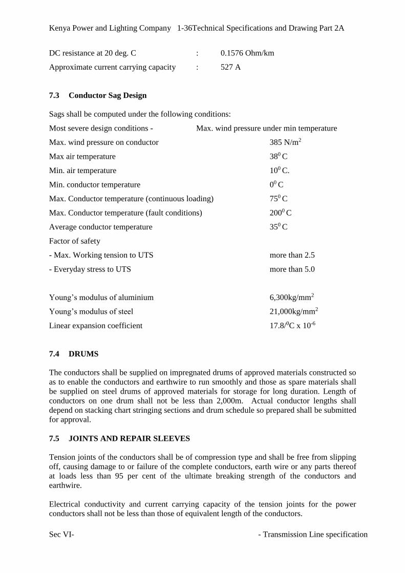
Kenya Power and Lighting Company 1-36Technical Specifications and Drawing Part 2A
Sec VI- - Transmission Line specification
DC resistance at 20 deg. C : 0.1576 Ohm/km
Approximate current carrying capacity : 527 A
7.3 Conductor Sag Design
Sags shall be computed under the following conditions:
Most severe design conditions - Max. wind pressure under min temperature
Max. wind pressure on conductor 385 N/m2
Max air temperature 380 C
Min. air temperature 100 C.
Min. conductor temperature 00 C
Max. Conductor temperature (continuous loading) 750 C
Max. Conductor temperature (fault conditions) 2000 C
Average conductor temperature 350 C
Factor of safety
- Max. Working tension to UTS more than 2.5
- Everyday stress to UTS more than 5.0
Young’s modulus of aluminium 6,300kg/mm2
Young’s modulus of steel 21,000kg/mm2
Linear expansion coefficient 17.8/0C x 10-6
7.4 DRUMS
The conductors shall be supplied on impregnated drums of approved materials constructed so
as to enable the conductors and earthwire to run smoothly and those as spare materials shall
be supplied on steel drums of approved materials for storage for long duration. Length of
conductors on one drum shall not be less than 2,000m. Actual conductor lengths shall
depend on stacking chart stringing sections and drum schedule so prepared shall be submitted
for approval.
7.5 JOINTS AND REPAIR SLEEVES
Tension joints of the conductors shall be of compression type and shall be free from slipping
off, causing damage to or failure of the complete conductors, earth wire or any parts thereof
at loads less than 95 per cent of the ultimate breaking strength of the conductors and
earthwire.
Electrical conductivity and current carrying capacity of the tension joints for the power
conductors shall not be less than those of equivalent length of the conductors.

Kenya Power and Lighting Company 1-37Technical Specifications and Drawing Part 2A
Sec VI- - Transmission Line specification
The cut ends of steel wires and steel component inside the joint shall be protected from the
weather in an effective and permanent manner.
Aluminium sleeves shall have plugholes for injecting compound.
All tension joints shall be supplied with aluminium fool-proof gauges or anti-displacement
pins for correct positioning, adequate quantity of filling compound in injectors and
aluminium collars for gap filling.
Full details of the joints including an illustration of practices for filling the air gap between
sleeves, method of correct positioning of steel sleeves, gauges for ascertaining the
compressed size, etc. shall be submitted with the tender.
Repair sleeves for the power conductors shall be of the compression type and the conditions
stated above for the tension joints shall apply to the repair sleeves where applicable.
7.6 Accessories for Power Conductors and Earth wire
In order to prevent fatigue of power conductors and earth wires due to repeated vibrations
caused by breeze, the following countermeasures shall be applied.
a) Trunnion type suspension clamps
b) Vibration dampers
c) Armour rods.
7.6.1 Trunnion type suspension clamps
Suspension clamps shall be of trunnion type, made of aluminium alloy and as light as
possible. They shall be designed to avoid any possibility of deforming the stranded
conductors and earth wires and of separating the individual strands and shall be free to pivot
in the vertical plane containing the conductors and earth wires.
Suspension clamps except jumper suspension sets shall have a suitable dimension for
clamping the conductor with preformed armour rods; and shall not permit the complete
conductor with armour rods to split at load less than 2,250kg for ACSR. Particular attention
shall be paid to the elimination of corona emission from all parts of the suspension clamp.
7.6.2 Vibration Dampers
Vibration dampers shall be of Stockbridge type for both conductors and earth wire. The
dampers shall be applied in all conductors and earthwires in every span except slack spans
into the substations. The dampers shall be designed to be attached to the conductors and
earthwire in a manner, which will prevent damage thereto and free drop of the weight in
service. Clamping bolts shall be provided with domed self-locking nuts designed to prevent
corrosion to the thread.
The nominal weight of damper shall be 12 pounds (5.44kg) for the conductors and 4 pounds
(1.81kg) for the earthwire. The numbers of the dampers to be installed per span shall be:

Kenya Power and Lighting Company 1-38Technical Specifications and Drawing Part 2A
Sec VI- - Transmission Line specification
a) 2 pieces per conductor or earthwire for spans up to 600 m and,
b) 4pieces for the spans longer than 600 m.
First and second dampers will be positioned at 1.1m and 2.2m for power conductors and 0.6m
and 1.2 m for earthwires respectively from the centre of suspension clamps or from the mouth
of tension clamps.
7.6.3 Armour Rods
Preformed armour rods shall be applied to all suspension points of the power conductors
except jumper suspension points.
Suspension clamps for those conductors protected by armour rods shall be suitable for the
enlarged conductors.
7.7 CORONA AND RADIO INTERFERENCE
The design of all line conductor fittings, vibration dampers, etc., shall avoid sharp corners or
projections which would produce high electrical stress in normal working. The design of
adjacent metal parts and matching surfaces should be such as to maintain good electrical
contact under service conditions. Particular care shall be taken during manufacture of
conductors and fittings and during subsequent handling to ensure smooth surfaces free from
abrasion.

Kenya Power and Lighting Company 1-39Technical Specifications and Drawing Part 2A
Sec VI- - Transmission Line specification
SECTION 8
8 OPTICAL FIBRE GROUND WIRE
8.1 TECHNICAL DESCRIPTION
The transmission line earth wire integrating optical fibres shall be of design and construction
to ensure long service with high economy and low maintenance costs. It shall be suitable in
every respect for continuous operation at nominal parameters as well as in transient operating
conditions under the climatic conditions peculiar to the site.
The OPGW shall incorporate at least 48 optical fibres. The fibre optic earth wire shall comprise
an optical sub-unit containing optical fibres over which shall be laid aluminium, aluminium
alloy or aluminium coated steel strands. The clad steel wire incorporated in fibre optic earth
wire shall comply with the requirements of IEC 61232. Shaped aluminium or aluminium
alloy wire sections shall conform to the requirements of the appropriate IEC standard. Other
OPGW types are acceptable if the required performance characteristics are met.
All materials used shall be of the best quality and workmanship, and shall be of the highest class
throughout with the designs and dimensions of all parts such that the stresses to which the
OPGW are subjected to shall not render them liable to distortion or damage under the most
severe conditions encountered during installation as well as in service.
Special attention shall be paid to the OPGW stranding process to ensure the necessary tightness
between different layers in order to avoid slippage or relative movement of strands or cage
formation during stringing.
Stranding tolerances as well as inspection and testing shall be as per IEC 61089 as far as
applicable, and to the respective manufacturing standards.
The OPGW manufacturer shall have ISO 9000 quality assurance system certified and shall
prove a minimum experience in successful supply of similar OPGW in the last 5 years.
The OPGW installation shall include all cable fittings (tension and suspension spirals,
vibration dampers, earth connection etc.), joint boxes, termination boxes, fibre connectors
and other accessories required for a complete working fibre link.The earth wire fittings and
optical joint boxes shall be type approved.
The optical sub-unit shall withstand the temperature rise associated with the specified
lightning fault current flowing in the earthwire without damage. The fibre optic earthwire
(OPGW) shall be manufactured in continuous lengths of appropriate lengths to keep joints to
a minimum.
The overall system design of the fibre optic system shall meet the following minimum
requirements:
a) Single failure or degradation in any optical fibre not more than one year averaged
over five years;

Kenya Power and Lighting Company 1-40Technical Specifications and Drawing Part 2A
Sec VI- - Transmission Line specification
b) Failures or degradations affecting more than one optical fibre, not more than one in
ten years;
c) Increase in optical system transmission attenuation due to accumulated ageing and
other effects at the end of five years, not more than 0.05 dB/km.
3.17.3.1 Optical fibre parameter and performance
The OPGW, access cables and underground cables shall have at least 48 (forty-eight) single
mode optical fibres with following characteristics:
Transmission wavelength: 1310 nm and 1550 nm
Mode field diameter: 9.0 to 11.5 micrometers (m), including tolerances
Optical cladding diameter: 125 m ± 2.0%
Cable Attenuation: not greater than 0.40 dB/km for every fibre in every drum at optical
wavelength of 1310 nm; and not greater than 0.25 dB/km for every fibre in every drum at
optical wavelength of 1550 nm
Joint attenuation: not greater than 0.1 dB at optical wavelength of 1310 nm and not greater
than 0.2 dB at 1550 nm for every fibre, measured on the fully installed joint
Total dispersion: not greater than 3.5 ps/km.nm at optical wavelength of 1310 nm and not
greater than 19.0 ps/km.nm at optical wavelength of 1550 nm
Core numerical aperture: less than 0.23
Life span: greater than 30 years
The Contractor is required to supply a graph of attenuation versus wavelength over the range of
1200 nm to 1600 nm
No joints shall be allowed in any fibre in any drum length.
Discontinuities will be acceptable if:
Less than 0.10 dB in magnitude measured at 1310 nm, and
OTDR traces from both ends of the cable at 1310 and 1550 nm wavelength show a
difference of less than 0.05 dB/km for every fibre in every drum.
Power Meter & Light source. The test shall be used to verify that the measured loss is in
average equal or less than the calculated link budget.
The Contractor shall state the refractive index of the optical fibres at 1310 nm and 1550 nm.
8.2 OPTICAL FIBRES
Optical fibres shall be single mode fibre and shall conform to IEC 793-2-BI.
The fibre coating material shall be mechanically strippable. The optical fibres shall be
capable of being jointed by fusion technique.
There shall be no measurable long term or short-term optical attenuation change due to the
temperature rise associated with a fault current flowing in an earth wire, or a lightning strike
on the earth wire.

Kenya Power and Lighting Company 1-41Technical Specifications and Drawing Part 2A
Sec VI- - Transmission Line specification
8.3 OPGW FITTINGS
The fibre optic earth wire shall be with approved conductor fittings. The application of these
fittings shall not damage the earth wire or fibres, either mechanically or optically.
At each support, a bypass device shall be provided to guide the cable around the earth wire
fittings associated with the support.
8.4 OPTICAL JOINT BOXES
Optical joint boxes shall be provided to protect the splice joint of optical fibres, either when
individual lengths of the fibre optic OPGW, are jointed or between the fibre optic earth wire
and the underground fibre optic cable.
The joint boxes shall consist of external steel or die cast aluminium housing providing
protection to IEC 529 IP 44 and an internal die cast aluminium or high impact plastic ABS
box to IEC 529 IP54
The external housing shall be designed so that the rainwater is directed away from the door
and there shall be no water ingress when the door is opened.
The joint boxes shall be supplied complete with all fittings to secure and seal the cable in the
gland plates or blank the unused spigots. The cable cleats to secure the fibre optic OPGW or
underground cable shall be fitted inside the box. The cleats shall not have a detrimental effect
on the performance of the optical fibres when tightened to the recommended torque.
The top and bottom of the joint box shall be vented and the vents provided with the vermin
shields.
The box shall be supplied complete with internal splice cassettes to accommodate the
required number of splices. The glands shall be fitted to accommodate either the fibre optic
OPGW or underground fibre optic cable.
8.5 FIXING CLAMPS
A bolted clamping system shall be used to attach the OPGW to the inside of the support,
without drilling or modifications to the support steel work.
The attachment clamps shall be capable of being attached and detached from the support,
without affecting the OPGW.
8.6 MATERIALS
8.6.1 Fibre optic earth wire materials
External aluminium, aluminium alloy or aluminium coated steel strands.

Kenya Power and Lighting Company 1-42Technical Specifications and Drawing Part 2A
Sec VI- - Transmission Line specification
8.6.2 Optical Joint boxes
Optical joint boxes shall be made from either a suitable grade of aluminium alloy complying
with the requirements of BS 1490 and / or BS EN 1676 or steel complying with requirements
of BS 3100
8.6.3 Fixing Clamps
Fixing clamps shall be made from a suitable grade of aluminium alloy complying with the
requirements of BS 1490 and / or BS EN 1676. Bolts shall be made from mild steel grade
S275JR to BS EN 10 025. Bolts and nuts shall be ISO Metric Black Hexagon to BS 4190 and
shall unless otherwise specified be threaded ISO Metric Coarse Pitch to BS 3643: Part 2,
Tolerance Class 7h/8g.
8.7 PROTECTIVE TREATMENT
8.7.1 Fibre optic earth wire
Where two layers of wire strands are provided over the optical sub-unit, the external surface
of the optical sub-unit and the inner strand layer shall be greased, using approved conductor
grease.
8.7.2 Ingress of Moisture
The cable shall be capped before shipment to prevent the ingress of water.
8.7.3 Optical Joint boxes
Optical joint boxes (steel exterior) shall be hot dipped galvanised after manufacture to meet
the requirements of BS 729.
8.8 INSTALLATION
8.8.1 General
The supplier of the OPGW shall be responsible for the supervision of installation by the
Contractor; to ensure that system reliability requirements are met.
8.8.2 Workmanship
The Contractor shall ensure that the fibre optic cable are not strained or damaged either
mechanically or optically during stringing and/ or jointing.
8.8.3 Fibre optic joints
Optical fibre joints in the OPGW, or between the OPGW and the non-metallic underground
fibre optic cable, shall be housed in optical joint boxes. The joint boxes shall be located
immediately above the anti-climbing device for convenient access by technical personnel. All
joint boxes shall be earthed to the support steel work using approved multi-wire / multi-strand
flexible aluminium earth bond.
8.9 TERMINAL EQUIPMENT
The All fibres of the OPGW shall be terminated at an Optical joint box provided on the
terminal tower by the contractor. Lead in cable shall be provided at the substations by the
employer, to connect the OPGW to the terminal equipment.

Kenya Power and Lighting Company 1-43Technical Specifications and Drawing Part 2A
Sec VI- - Transmission Line specification
8.9.1 Scope of Work
The Contractor shall include detailed system design, manufacture, supply, installation,
testing, commissioning, remedying of defects, maintaining the works during the defects
liability period and any incidental work necessary for the proper completion of the work in
accordance with this contract.
The existing UEB-Juja line already has an optical fibre earth wire. The Contractor shall open
this connection, and complete the OPGW link from Lessos (Along UEB line) to the new KPC
Nakuru Depot SS, and the subsequent extension from the new KPC Nakuru Depot SS to
Lanet SS (Along Juja line).
Detailed requirements are as follows:-
System design – The system design and preparation of Contractor's drawings to
approval of the Engineer
Supply and installation of fibre optic cable including mounting hardware and splicing
Factory testing of the OPGW prior to delivery.
Testing and commissioning of the systems up to the terminal joint box at KPC Nakuru
depot substation
8.10 QUALITY CONTROL
FATs shall be carried out for the OPGW.During the attendance, the Contractor shall give the
Employer’s persons a brief explanation on design, manufacture, operation and maintenance
of the materials and equipment.
8.10.1 Types of Tests
Type, sample and routine tests shall be undertaken on the OPGW, their associated fittings,
non-metallic underground fibre optic cable and optical fibres in accordance with the
requirements of specification, CCITT G652, IEC 793 and IEC 794 as appropriate.
8.10.2 OPGW Tests
a) Fatigue
The Contractor shall submit documentary evidence to show the fatigue life of the OPGW
including that of the optical sub-unit compared to that of a conventional conductor of similar
characteristics e.g. diameter, mass, stranding etc.
b) Stress-Strain
A sample of OPGW not less that 10m length, complete with the proposed end fittings shall be
subject to a stress-strain test. The test shall be undertaken in accordance with IEC 1089
Annex B and the measuring techniques in accordance with IEC 794-1-E1.
c) Tensile performance
The test shall be undertaken in accordance with the load conditions specified in IEC 1089
Annex B and the measuring techniques in accordance with IEC 794-1-E1.

Kenya Power and Lighting Company 1-44Technical Specifications and Drawing Part 2A
Sec VI- - Transmission Line specification
d) Crush and Impact The test shall be undertaken in accordance with the recommendations of IEC 7941-1-E3 and
IEC –794-1-E4.
The crush test shall be undertaken by applying a 10kN load for 1 minute to the OPGW via
two 50mm x 50 mm flat plates.
The impact test shall be undertaken by dropping a 4 kg weight from a height of 150 mm onto
the end of a 20mm diameter steel mandrel placed on the OPGW. These should be done 20
times.
e) Temperature cycling
The optical performance under temperature cycling shall be tested in accordance with IEC
794-1-F1 with specified temperature ranges for a duration of 4 hours. The test should be
undertaken twice.
f) Water Ingress
The optical sub-unit shall be tested for water ingress in accordance with IEC 794-1-F5
g) Fault Current
A sample of OPGW not less than 2 metres in length shall be subjected to a fault current
pulse. The test shall be performed twice with an interval of 30 minutes between tests. After
the second impulse the OPGW shall be dismantled and the optical cable examined throughout
its length for any signs of deterioration.
h) Lightning Strike
Tests shall be carried out to verify the effectiveness of the OPGW to withstand the effects of
a lightning strike. The test shall consider both an initial stroke and a follow through. The test
shall be carried out on a sample of OPGW not less than 2 metres long. The acceptable criteria
shall be that earthwires’ calculated residual strength is not less than 90 percent of the original
stated ultimate strength.
8.10.3 Optical Fibres
Optical fibres shall be tested in accordance with the requirements of IEC 793.
8.10.4 Optical joint Boxes
Optical joint boxes shall be visually inspected to ensure they meet the specified requirements.
8.10.5 Non- metallic underground Fibre Optic cable
Non-metallic underground fibre optic cable and the optical fibres shall be tested in
accordance with the requirements of IEC 793 and IEC 794 as appropriate.
8.10.6 Fibre Optic cable
All fibre optic cables shall be tested prior to dispatch using an OTDR on each fibre and other
tests detailed in this document.
8.10.7 Test Certificates
Test records, covering type and sample tests shall be provided.

Kenya Power and Lighting Company 1-45Technical Specifications and Drawing Part 2A
Sec VI- - Transmission Line specification
APPENDIX 8.A.4
TEST EQUIPMENT
The following test equipment shall be supplied and shall remain the property of the Employer
after the completion of the site installation. The equipment shall be delivered to the
Employer’s site depot complete with suitable packaging after completion of the installation
tests.
a) One-Portable Optical Time Domain Reflectometer (OTDR) with 1300 and 1550 nm
modules. Storage and printing capabilities of traces shall be provided;
b) Two- Portable Optical Power meters for 1300 and 1550nm;
c) Two- Portable High Stability Laser Sources for optical power measurements at 1300
and 1550 nm wavelengths:
d) An optical fibre fusion splicing machine which shall be of the automatic type,
designed to carry out fibre core alignment, pre-cleaning and fusion splicing as a fully
integrated and properly co-ordinated sequence of functions. It shall only be necessary
for the operator to correctly prepare the fibre ends and carry out preliminary
alignment prior to initiating the slicing sequence. Optical devices and light sources
that are utilised in the fibre system shall form an integral part of the fusion splicing
machine and the alignment process. Devices that rely on the use of remotely mounted
light sources will not be acceptable. The fusion splicing machine shall be capable of
producing splices with an average attenuation value of less than 0.05 dB.
e) Digital galvanization thickness gauge.
f) Schmidt concrete hardness test hammer.

Kenya Power and Lighting Company 1-46Technical Specifications and Drawing Part 2A
Sec VI- - Transmission Line specification
SECTION 9
9 LINE INSULATION
The transmission line for the project is aligned on an elevation level of 200 above sea level.
The area has high humidity levels, tropical sunshine and prone to medium to heavy pollution
by agricultural and industrial activities.
Silicon-rubber long-rod type Composite Insulators of the approved type shall be used to
support the power conductors of the Transmission line. All insulator units will be composed
of top and bottom arcing rings to equalize the voltage distribution over the insulator. The top
shed of the insulators shall also have a larger diameter to prevent waste from birds and
animals tracking down along the insulator.
9.1 INSULATORS DESIGN
The insulator units shall be designed to withstand the design service voltages including
lightning, switching and power frequency, the mechanical loads relevant to the installation-
service-maintenance conditions, the service temperature and environmental effects. Internal
stresses due to expansion and contraction of any part of the insulator unit shall not lead to
deterioration.
The insulators should withstand wind pressures of up to a maximum of 385N/ m2.
The design of insulator units shall be with end over mould or such as to avoid local corona
formation and no significant radio interferences shall be exhibited. The long rod Insulator
units shall comply with the requirements of IEC 61109.
9.2 FITTINGS
All fittings to make each composite insulator set complete for beneficiary use shall be
supplied and included in the rate for each insulator unit. Such bolts, nuts, washers, cotter pins
and retaining pins with necessary spares as may be necessary for the use for erection shall be
deemed to be included in the appropriate items.
Ball and socket couplings shall be in accordance with the requirements of IEC 60120/16.
Sockets shall have “R” type security clips in accordance with the requirements of IEC 60372.
Clevis tongue couplings shall be in accordance with the requirements of IEC 60471.
All ferrous fittings shall be made of steel, ductile iron or malleable iron hot dip galvanized,
and shall have sufficient strength for abrasion and weariness produced by repeated vibration.
Cotter pins shall be made of non-ferrous metal or stainless steel and designed as the self-
locking type.
The arcing ring shall be provided for the top and bottom of each insulator string and shall be
of such design and shape that it reduces the voltage across the part of the insulator adjacent to
the conductor for each insulator string, to a value which prevents visual corona formation on
the metal caps and pins of the insulators and shall minimize the Radio / Video interference

Kenya Power and Lighting Company 1-47Technical Specifications and Drawing Part 2A
Sec VI- - Transmission Line specification
voltage from complete insulator and hardware assemblies when operated at the voltage up to
420 KV.
The arcing rings shall be of such design that when added to suspension and tension
assemblies, the resulting flash-over values of the complete insulator string shall not be
reduced below the percentage indicated hereunder, of corresponding flash over values with
the rings omitted.
The percentages are:
a) Wet 50 Hz: 100%
b) 1.2 / 50 Impulse: 96%
The rings shall be of hot dip galvanized steel or Aluminium tube having outside diameter as
required for corona control and minimum thickness of 2.5mm. Both inner and outer surfaces
shall be galvanized to the required specifications (BS 729). The details of the rings, brackets
and methods of mounting shall be of such design that the rings may be readily replaced under
‘hotline’ maintenance.
The horizontal distance between corona rings at suspension rings at suspension insulator
strings shall be kept as small as practicable to accomplish the required reduction in Radio/
Video Interference (RVI).
All the accessories and the fitting offered against this specification shall be subjected to
corona test. The corona shall not take place and shall extinguish at the voltages specified i.e.
when a voltage of the specified value applied (Phase to Neutral i.e. RMS) the corona shall
appear and shall disappear again at the specified value of voltage.
9.3 Pollution
The design of insulator units should take into account the principles contained in the IEC
60815 for heavy pollution environment. For this projectthe minimum creepage value of 31
mm/kV shall be applied (Creepage distance of 4495 mm).
9.4 Zinc Collars
The insulator unit cap and pin shall be fitted with zinc-collared pins to prevent cracking due
to pin corrosion caused by the effects of pollution and high humidity in the project area.
9.5 Insulator Protective Device
The design of insulator fittings including corona shields shall comply with the following
requirements:
a) Shall effectively protect the insulator unit and fittings from damage caused by power
arcs.
b) Shall effectively improve the voltage distribution along the insulator unit;
c) Shall effectively improve the corona performance of the insulator unit.
d) Shall be designed in such a way as not to subject to breakage fatigue due to wind
induced vibration;
e) Shall withstand the specified mechanical load
f) Shall be suitable for live line maintenance

Kenya Power and Lighting Company 1-48Technical Specifications and Drawing Part 2A
Sec VI- - Transmission Line specification
9.6 Materials
The silicon rubber composite insulator shall comply with requirements of IEC 61109. The
tension bearing material shall be E-CR Fibre Glass and the housing and sheds made of HTV
silicone rubber.
Insulator caps and pin bases of malleable cast iron shall be manufactured from a suitable
grade of MCI complying with the requirement of BS EN 1563 for spheroidal graphite or BS
EN 1562 for white heart and peralitic.
Insulator end fitting of forged or cast aluminium alloy shall be manufactured from a suitable
grade of aluminium alloy complying with the requirements of BS 1472 or BS 1490 and/or BS
EN 1676 respectively.
Security ‘R” clips shall be of phosphor-bronze composition in accordance with the
requirements of BS 2870 and supplied in the half-hard condition with a minimum harness of
155 VPN
Zinc collars shall have a total impurity not greater than 0.05 percent and shall comply with
the requirement of BS EN 1179.
All insulator caps, bases and pins shall either be inherently resistant to atmospheric corrosion
or a suitably protected against corrosion, such as may occur in transit, storage and in service.
All ferrous parts which will be exposed to the atmosphere in service, except those made in
the appropriate grade of stainless steel, shall be protected by hot-dipped galvanising to
comply with the requirements of BS 729.
9.7 TESTS
Type, sample and routine tests shall be undertaken on the insulator units in accordance with
the IEC 61109.
9.8 MINIMUM CLEARANCES
9.8.1 Minimum Clearance of Live Parts to Towers
As Appendix 9.A.2 below
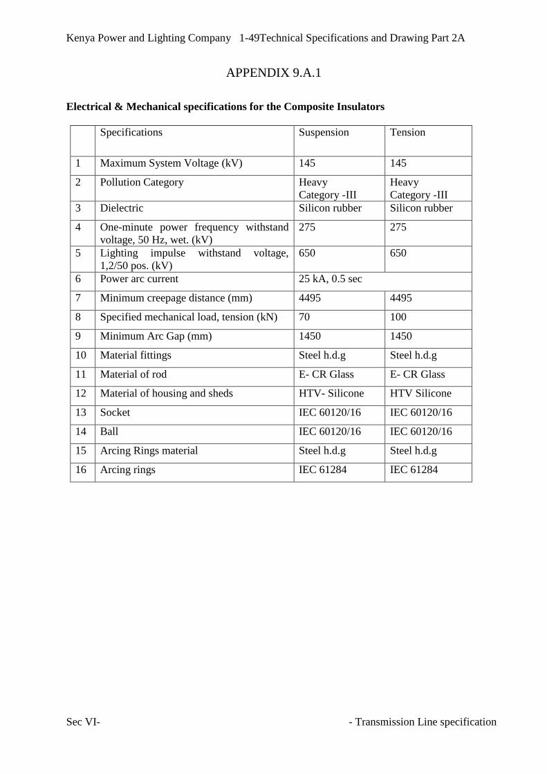
Kenya Power and Lighting Company 1-49Technical Specifications and Drawing Part 2A
Sec VI- - Transmission Line specification
APPENDIX 9.A.1
Electrical & Mechanical specifications for the Composite Insulators
Specifications Suspension Tension
1 Maximum System Voltage (kV) 145 145
2 Pollution Category Heavy
Category -III
Heavy
Category -III
3 Dielectric Silicon rubber Silicon rubber
4 One-minute power frequency withstand
voltage, 50 Hz, wet. (kV)
275 275
5 Lighting impulse withstand voltage,
1,2/50 pos. (kV)
650 650
6 Power arc current 25 kA, 0.5 sec
7 Minimum creepage distance (mm) 4495 4495
8 Specified mechanical load, tension (kN) 70 100
9 Minimum Arc Gap (mm) 1450 1450
10 Material fittings Steel h.d.g Steel h.d.g
11 Material of rod E- CR Glass E- CR Glass
12 Material of housing and sheds HTV- Silicone HTV Silicone
13 Socket IEC 60120/16 IEC 60120/16
14 Ball IEC 60120/16 IEC 60120/16
15 Arcing Rings material Steel h.d.g Steel h.d.g
16 Arcing rings IEC 61284 IEC 61284

Kenya Power and Lighting Company 1-50Technical Specifications and Drawing Part 2A
Sec VI- - Transmission Line specification
APPENDIX 9.A.2
MINIMUM CLEARANCES
Minimum clearance of live parts to towers
The minimum electrical clearances of live parts to earthed structures for the project shall be
as follows (See Figures 1.A.2):
a) In still air (vertical position) : 1350mm
b) Under 200 swing of suspension insulator set or jumper conductors : 1350mm
c) Under 400 swing of suspension insulator set or jumper conductors : 1140mm
d) Under 600 swing of suspension insulator set or jumper conductors : 830mm
Minimum Ground clearances of conductors
Above general terrain 7.2m
Above main roads 7.5m
Above other Power lines 3.2m
Above Telephone lines 3.2m
Above railways 8.5m

Kenya Power and Lighting Company 1-51Technical Specifications and Drawing Part 2A
Sec VI- - Transmission Line specification
SECTION 10
10 TOWERS
10.1 TYPE OF TOWER
The line shall be a Single circuit of power conductor Lynx with overhead Optical Ground
Wire.
Towers shall be self-supporting and broad base hot deep galvanised steel lattice type with
body and hillside extensions. The hillside extensions shall be applied for tower legs on the
slope so that legs are suited to the original slope of tower site and also that excessive land
cutting around foundations and land collapse is prevented.
The following tower types shall be designed for the project in order to meet various tower
positions and loadings economically.
(a) Type-S : Use at tangential positions or angle points up to 2 degrees of
horizontal deviation, provided with suspension type insulator
sets.
(b) Type-L : Use at positions of light angle up to 15 degrees of horizontal
angle deviation with tension type insulator sets.
(c) Type-M : Use at positions of medium angle up to 30 degrees of
horizontal angle deviation with tension insulator sets.
(d) Type-H : Use at positions of heavy angle up to 60 degrees of horizontal
angle deviation with tension insulator sets.
(e) Type-HS : Use at positions of specifically heavy angle up to 75 degrees
of horizontal angle deviation with tension type insulator sets.
(f) Type-T : Use at positions of line termination or 90 degrees of horizontal
angle deviation with tension type insulator sets.
The actual types and number of towers shall depend on the profile of the selected route and
actual tower spotting.
10.2 TOWER DESIGN GENERAL ARRANGEMENT
Towers shall have the general arrangements and configurations shown in the drawings
included with the specification. Please note that the drawing only give the general tower
outline. Design of the towers shall be done by the contractor. Tower design with a high peak
for a single ground wire shall be acceptable provided design calculations show the
effectiveness of such aerial earth protection. They shall be designed to resist the specified
ultimate system loading. Clearances between live parts and supporting steelwork and between
the phase conductors and ground or other obstacles shall be as specified.

Kenya Power and Lighting Company 1-52Technical Specifications and Drawing Part 2A
Sec VI- - Transmission Line specification
All tower designs shall be such as to facilitate inspection, painting, maintenance, repairs and
operation with the continuity of supply being the prime consideration.
The design shall be such that the number of different parts shall be as few as possible to
facilitate transport, erection and inspection. The maximum weight of the heaviest single
member should be limited to that within the normal lifting capability of the proposed erection
equipment.
Main leg members of lattice steel towers shall be formed of the maximum single lengths,
appropriate to the body or leg extensions and shall not without the Employer’s approval
incorporate additional spliced sections.
For lattice steel towers a fully triangulated system of bracings shall preferably be adopted. If
full triangulation is not adopted, the overall stability and secondary bending stresses must be
considered in the design.
Where fabrication processes employed adversely affect the material properties, or introduce
zones of high stress concentration the overall design of the structures shall take such factors
into account.
Cross-arms shall be so arranged that they can be disconnected in the plane of the longitudinal
face of the support without disturbing any members forming part of the support body.
The cross-arms should be designed to take and be compatible with the AB CHANCE Live
Line maintenance tools and equipment.
Appropriate bird guard protective devises shall be installed to keep away birds from roosting
directly over the insulator units.
10.2.1 Height of Towers
Height of towers shall be determined in the under-mentioned way:
H = Gc + Sg + Li + Hc + Hg
Where,
H = Total height of tower.
Gc = Necessary ground clearance of power conductors above ground or
other objectives.
Sg = Maximum conductor sag
Li = Length of a suspension insulator set, but nil for a tension type towers.
Hc = Vertical spacing of upper conductor cross -arm spacing
Hg = Vertical spacing between upper conductor cross-arm and overhead earthwire.
Towers shall be provided with body extensions in a 3 m step to a standard height for
maintaining necessary conductor ground clearance mentioned in APPENDIX 1.A.2 on
various ground profiles. In addition to the body extensions, each leg will have hillside
extensions in a 1 m step to suit for the original ground slope and ensure that cutting ground to
level setting will not be used. Standard tower structures are shown in Appendix 1.A.1 as well
as insulation clearance diagram of conductors.

Kenya Power and Lighting Company 1-53Technical Specifications and Drawing Part 2A
Sec VI- - Transmission Line specification
10.2.2 Design Span
The design of all towers shall provide for the following basic, wind and weight spans:
Type of Tower S L M H HS T
Basic span (m) 350 350 350 350 350 350
Wind span (m) 350 350 350 350 350 350
Weight span (m) 700 1,200 1,200 1,200 1,200 1,200
Uplift Weight (m) 0 -300 -300 -300 -300 -300
The term basic span means the horizontal distance between centres of adjacent supports on
the level ground which the height of standard towers is derived with the specified conductor
clearances to ground in still air at maximum temperature.
The term wind span means half the sum of adjacent horizontal span lengths supported on any
one tower.
The term uplift weight means the weights of conductors and overhead earthwire supported
upwards at any one tower for reinforcing strength of cross arms.
10.2.3 Design Loads
Structural loading shall refer, ASCE Manual and Report on Engineering Practice No. 74 -
1991 “Guidelines for electrical transmission line structural loading”.
The following loads shall be applied in the design of towers:
(a) Wind Loads - on power conductors and overhead earthwire : 385N/m2
(On the projected area of conductor or wire)
- On tower structures : 690N/ m2
(On the projected area of structure members)
- On insulator sets : 385N/ m2
(b) Maximum working Tensions of Conductor and Earthwire
- Power conductor Lynx : 22,400 N
- Overhead optical fibre earthwire : 14,100 N
(c) Vertical Loads
- Tower structures:actual weights of tower structures including accessories
- Power conductors: Weight of conductors of specified weight span with
accessories
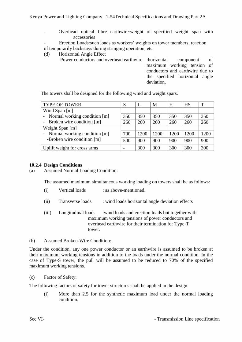
Kenya Power and Lighting Company 1-54Technical Specifications and Drawing Part 2A
Sec VI- - Transmission Line specification
- Overhead optical fibre earthwire:weight of specified weight span with
accessories
- Erection Loads:such loads as workers’ weights on tower members, reaction
of temporarily backstays during stringing operation, etc
(d) Horizontal Angle Effect
-Power conductors and overhead earthwire :horizontal component of
maximum working tension of
conductors and earthwire due to
the specified horizontal angle
deviation.
The towers shall be designed for the following wind and weight spars.
TYPE OF TOWER S L M H HS T
Wind Span [m]
- Normal working condition [m]
- Broken wire condition [m]
350 350 350 350 350 350
260 260 260 260 260 260
Weight Span [m]
- Normal working condition [m]
-Broken wire condition [m]
700 1200 1200 1200 1200 1200
500 900 900 900 900 900
Uplift weight for cross arms - 300 300 300 300 300
10.2.4 Design Conditions
(a) Assumed Normal Loading Condition:
The assumed maximum simultaneous working loading on towers shall be as follows:
(i) Vertical loads : as above-mentioned.
(ii) Transverse loads : wind loads horizontal angle deviation effects
(iii) Longitudinal loads :wind loads and erection loads but together with
maximum working tensions of power conductors and
overhead earthwire for their termination for Type-T
tower.
(b) Assumed Broken-Wire Condition:
Under the condition, any one power conductor or an earthwire is assumed to be broken at
their maximum working tensions in addition to the loads under the normal condition. In the
case of Type-S tower, the pull will be assumed to be reduced to 70% of the specified
maximum working tensions.
(c) Factor of Safety:
The following factors of safety for tower structures shall be applied in the design.
(i) More than 2.5 for the synthetic maximum load under the normal loading
condition.

Kenya Power and Lighting Company 1-55Technical Specifications and Drawing Part 2A
Sec VI- - Transmission Line specification
(ii) More than 1.5 for the synthetic maximum load under the broken-wire
condition.
Those factors of safety shall be proved under tower loading tests on the proto-type towers in
the manufacturer’s testing station, and there should be no failure or permanent distortion
during the tests when 100% loading is sustained for five minutes.
10.2.5 Design of Towers
Latticed steel structures shall be designed with geometric configurations based on structural
strength, electrical, economic, and safety requirements. Member forces caused by the design
factored loads shall be determined by established principles of structural analysis.
Each type of towers shall be designed so that no failure or permanent distortion shall occur
when tested with applied force equivalent to 2.5 times the maximum simultaneous working
loadings specified in the Clause 10.2.4 [Normal Working Loading] and also equivalent to 1.5
times the maximum simultaneous working loadings resulting from the assumed broken wire
condition. Design loads shall consider:
a) Minimum legislated levels
b) Client specifications including factors of safety,
c) Expected climatic conditions,
d) Line security provisions,
e) Design life of not less than 50 years,
f) Construction and maintenance operations.
The ultimate design stress, obtained from the working stress multiplied by the factor of safety
of 2.5 under the normal condition and 1.5 under the broken wire condition, in tension
members shall not exceed the yield point of materials. The ultimate design stress, obtained
from the working stress multiplied by the above mentioned factor of safety, in compression
members shall not exceed a figure obtained from an approved formula to be entered in
Tender based on the yield point of materials. Alternately, formulas in the American Society
of Civil Engineers standard for the design of self-supporting latticed steel transmission
structures ASCE 10- 97 and ASCE Manual and Report on Engineering Practice No. 74
guidelines for electrical transmission line structural loading shall refer.
Tower design report shall consist of full structural analysis report showing correctness of
dimensional detail calculations, tower profile/layout drawings, shop detail drawings, erection
drawings and bills of materials. Shop detail drawings shall be approved by the producing
utility Engineer of Record (EOR) regarding compliance with the purchaser’s specifications
and the strength requirements of the design.
Designed tower full scale prototype proof test to BS EN 60652: 2004 loading tests on
overhead line structures shall be conducted and approved before tower materials shop
production and delivery to site.
10.2.6 Materials and Fabrication
The towers shall be fabricated with mild and/or high tensile steel of the finest quality or other
approved materials, of which mechanical properties shall comply with Grade Fe 430 and Fe
510 specified in ISO 630-1980, BS 5950-1/2 or equivalent.

Kenya Power and Lighting Company 1-56Technical Specifications and Drawing Part 2A
Sec VI- - Transmission Line specification
No member of the tower shall be less than 8 mm in thickness and 50 mm in width of flange
for leg members of towers and main members of the cross-arm, and 6 mm and 45 mm for the
web and nominal members respectively.
The slenderness ratio shall not exceed 150 for the leg and arm members, 200 for the web
members and 250 for the nominal members as compression member and 350 for tension only
member.
All the connection shall be made by mild and/or high tensile steel bolts and nuts. No bolt
shall be less than 12 mm in diameter. All bolts and nuts shall be provided with approved
spring washers. Antitheft bolts shall be used from ground level to the tower anti-climb level.
Bolt holes shall not be more than 1.5 mm larger in diameter than the corresponding diameter
of bolts. Holes shall be drilled for the members not less than 13 mm in thickness. For the
members having thickness below 13 mm, holes may be drilled or punched, but the former is
preferred.
All the steel members should have clearly identifiable part numbers which enable quick
identification of similar parts. The letters ‘KPLC’ should also be inscribed on each bracing-
by punching or any other suitable method, with more than one inscription for parts of length
greater than 0.5m.
All burs shall be removed completely by reaming and smoothing before hot-deep
galvanising.
10.3 Tower Accessories
The following accessories shall be provided for every tower.
(i) Anti-climbing device and climbing steps: All towers will be provided with the
anti-climb device on each leg at the height of 3 m to 5 m above the highest ground
level at all tower locations. The device installed on the step-bolted legs shall be
provided on all towers. Gates shall be designed to open upwards only and shall be
secured with galvanised bolts and nuts. No padlocks are required.
Each tower shall be provided with step-bolts of an approved type on diagonal
sides of the tower at a spacing no more than 380mm, starting immediately above
the anti-climbing device and continuing to the earth wires.
Holes for removal step-bolts below the anti-climbing guards shall be provided at
not more than 380mm centres on the step legs.
(ii) Danger, Number and Helicopter patrol plates: Danger plate which shows
warning sign for tower climbing of other people than maintenance crew will be
provided on all towers.
Number plates which show tower number set serially from New Bamburi
132/33KV substation to the proposed Bamburi Cement 132KV metering station
will also be installed on every tower, both sides.

Kenya Power and Lighting Company 1-57Technical Specifications and Drawing Part 2A
Sec VI- - Transmission Line specification
On the top of every section tower, and every10th tower, additional number plates
will be provided on both sides to aid helicopter patrol over the transmission line.
Lettering and size of plates shall be to the Employer’s requirements, and should be
both sides of the line for clear identification when patrolling from either end.
All plates shall be of anti-corrosive material. If enamelled iron plates are used, the
whole surface of each plate including the back and edges shall be properly
covered and resistant to corrosion. On all plates the colours shall be permanent
and free from fading. With enamelled plates, washers or fibre or other approved
material shall be provided back and front of the securing bolts.
(iii) Tower Earthing: No separate earth conductor from top to bottom of towers is
required and earthing continuity will therefore depend on surface contact between
bolted members.
All structures shall be provided with means for connecting earthing devices at or
around nominal ground level, on each leg and for connecting earth wire bonds to
each top cross-arm or earth wire peak.
Each leg of towers will have an earthing rod underneath its foundation to act as
basic grounding required by good transmission line Engineering. Basic grounding
shall be constructed in such a way that isolation from the tower and concrete
foundation is possible to allow earthing survey if required during line service life.
Maximum earthing resistance of a tower is targeted on 10 ohms, and in case of
higher resistance than 10 ohms, additional horizontal counterpoise earthing system
will be added in the ground longitudinally to the line route with more than 50 cm
depth. The rate entered in the schedule of prices shall include for all necessary
fittings and shall be adjusted at the variation rate for increased or reduced fittings.
(iv) Aircraft Warning Devices: Due to the activity of aircraft in the vicinity of
certain parts of the transmission line, it shall be necessary to mount warning
spheres on earthwires at some locations. Aircraft warning spheres shall be
capable of being clamped securely to overhead earthwire. The sphere itself shall
be of plastic or fibreglass construction of at least 0.5m in diameter and coloured
orange or yellow as required by local regulations. The Contractor is to enter rates
against appropriate item in the schedule of prices for the above and he will be
advised early in the contract of actual requirements.
(v) Bolts: Where appropriate all metal parts hall be secured with bolts and nuts with
single spring washers. When in position the bolts shall project through the
corresponding nuts by at least three threads, but such projections shall not exceed
10mm. No screwed threads shall form part of a shearing plane between members.
In order to safeguard the tower members from theft; special anti-theft bolts shall
be applied from ground level up to the lower cross-arm level. The bolts shall be
approved by the Employer. The bolts are of the type that shears once the full
torque has been applied.

Kenya Power and Lighting Company 1-58Technical Specifications and Drawing Part 2A
Sec VI- - Transmission Line specification
The nuts of all bolts attaching phase conductor insulator set, earthwire sets,
maintenance brackets/plates shall be locked in an approved manner preferably by
locknuts.
The bolts of any one diameter in a tower shall be one grade of steel. Leg members
shall be joined in such a way that electrical continuity is maintained to ground.
(vi) Rectangular and Auxiliary Cross Arm
The type H, HS and T towers may be provided with rectangular arms where
horizontal angle exceeds 45 degree.
The prices of the rectangular arm set shall be included in the prices for the towers.
(vii) Spare Towers
One set of spare suspension tower shall be provided, and one set each for section
and angle towers used in the line. Spare bracings shall also be provided, sufficient
for two (2) standard towers up to the lower cross-arm level. Spares shall be packed
and labelled for easy identification. Packed spares shall be delivered in a minimum
20-foot ISO container storage to proposed Bamburi Cement 132/33kV substation.
10.4 MATERIALS
All steel shall comply with BS EN 10025 or BS EN 10210 as appropriate, unless
otherwise specified and shall be suitable for all the usual fabrication processes,
including hot and cold working within the specified ranges.
The quality of finished steel shall be in accordance with BS EN 10163. All steel shall
be free from blisters, scale, laminations, segregations and other defects. There shall be
no rolling laps at toes of angles or rolled-in mill scale.
Unless specified to the contrary the following grades of steel shall be applicable:
a) Mild steel shall be either grade S235JRG2 or S275JR.
b) High tensile steel shall be grade S355JR for sections less than 20 mm thick and
S355JO for sections greater or equal to 20mm thick, except for plates which shall
be greater or equal to 40mm thick.
10.5 WORKMANSHIP
All steel lattice members shall be cut to jig and all holes in steelwork shall be drilled or
punched to jig using CNC machine. All steel parts shall be carefully cut and holes located so
that when the members are in position the holes will be opposite each other before being
bolted up. The drilling, cutting, punching and bending of all fabricated steelwork shall be
such as to prevent any possibility of irregularity occurring which might introduce difficulty in
the erection of structures on site. High tensile steel members shall be bent hot. Care shall be
taken not to punch holes too close to the edge of members.

Kenya Power and Lighting Company 1-59Technical Specifications and Drawing Part 2A
Sec VI- - Transmission Line specification
Means shall be provided to enable the Employer to carry out such checking of members, as
he may consider necessary. Built-up sections, when finished, shall be true and free from all
kinks, twists and open joints and the materials shall not be strained in any way.
In order to check the workmanship, not less than 1 per cent, of the members corresponding to
each type of tower or cross-arm shall be selected at random and assembled to form complete
latticed supports or cross-arms in the presence of the Employer representative at the
manufacturer’s works.

Kenya Power and Lighting Company 1-60Technical Specifications and Drawing Part 2A
Sec VI- - Transmission Line specification
SECTION 11
11 FOUNDATIONS
11.1 General
Concrete pad and chimney type foundations will be applied to most of the towers, the design
of the concrete foundations of the towers shall be performed based on the requirements and
assumptions set out below, and the details of the design and drawings for each type of
foundations shall be submitted for approval.
Such design of foundations for the towers are subject to modifications to suit the site
conditions as indicated in writing by the Engineer during execution of the Contract without
any price adjustment of the items of the foundation stubs and foundations.
11.2 Concrete Block Foundation
Prior to determination of the type of foundation to be used, the contractor shall carry out
geotechnical investigations to BS 5930 and BS 1377 to establish field ground conditions.
The concrete foundations shall be done to meet the following standards:
BS 8004: Foundations
BS 8081: Code of practice for ground anchorages
BS 8100: Towers and masts
ASCE 10-97: Design of latticed towers
ASCE 74-1991: Guidelines for electrical transmission line structural loading
BS 8110: Structural use of concrete
BS 5328: Methods of specifying concrete
The types of the concrete foundations and natures of earth to be considered shall be as
follows:-
Shallow foundations shall be used for bearing capacity of more than 100kN/m2
For bearing capacity less than 100kN/ m2, special foundations shall apply. Suitable
special foundations shall be designed according to technical need and are further
classified as:
--Rock anchor for rocky foundations
--Raft foundations for swampy areas and
--Deep foundations, which require use of suitable piles.
All Structural Concrete shall be reinforced with deformed steel bars type 1 to BS 4449 and
structural design details to BS 8110 and structural steel detailing to BS 4466.
The angle of frustum of earth shall mean the angle vertical of earth frustum to resist the uplift
force and shall be established by geotechnical tests.
The factor of safety shall not be less than 2.5 under the normal working conditions and 1.5
under the broken wire conditions.

Kenya Power and Lighting Company 1-61Technical Specifications and Drawing Part 2A
Sec VI- - Transmission Line specification
The upper surfaces of the foundation pads shall be reinforced and sloped within 45 degrees to
the horizontal. The minimum thickness of the edges of base pad shall be not less than
300mm.
The frustum shall be assumed to start from the top edges of the pad. Where frustums overlap
each other, allowance shall be made for loss of uplift resistance.
Concrete shall cover any part of the top steelwork by at least 100mm and shall extend above
the ground level for the minimum height of 350mm. Additional 500mm minimum chimney
extension shall be provided to foots on lower side in sloping areas. The upper surface of
chimney shall be sloped to ensure drainage of water.
The cleats shall be attached by bolting at the base of each stub to assist in transfer of leg load
to the foundation pad as shown on drawing APPENDIX 1.A.3. Minimum portion of stub
loads in the design of cleats shall be assumed at 50 per cent.
11.3 Special Foundations
Besides the above mentioned concrete foundations, special foundations such as raft type
foundation, rock anchor, piled foundation or others may be required. Final type of foundation
to be applied for each tower shall be determined in accordance with results of soil
investigation performed by the Contractor during execution of the Contract.
For the purpose of tendering, basic designs shall be submitted with the tender under the
following assumptions, and prices for the special foundations shall be quoted based on the
design.
[a] Raft type foundation
The foundation shall be designed with the following specifications: ultimate bearing capacity
of 10ton/m2, soil weight of 1.4 ton/m3 and no angle of frustum of soil. Weights of reinforced
concrete and soil shall be taken as entirely submerged. Other design conditions specified in
this subsection will be applied.
[b] Piled foundation
Piles used for the foundation shall be either precast concrete pile with circular or square cross
section or in-situ concrete pile.
[i] Pile data
Pile diameter or dimension
- Circular cross section - Φ300 mm.
- Square cross section - 300 x 300 mm
- Pile depth below ground level - 12 m
- Ratio or ultimate bearing/uplift capacity of pile - 2.5: 1

Kenya Power and Lighting Company 1-62Technical Specifications and Drawing Part 2A
Sec VI- - Transmission Line specification
[ii] Uplift
The mass density of concrete below ground level shall be assumed as 1,600 kg/m3 to
allow for hydrostatic effects and similarly soil as 960 kg/m3. Additional weight of
concrete shall be included as necessary to provide the specified resistance to uplifting
under any condition. Where bored or driven piles are proposed having no specially
made bulb or enlarged concrete foot to provide positive uplift resistance but relying on
skin friction alone, at least 75% of the networking uplift force, and 50% of the net
broken wire uplift force shall be provided in dead weight of concrete, whichever is the
greater. The cost of such concrete shall be included in the piled foundation rate.
[iii] Compression
Mass density of plain concrete shall be assumed as 2,300 kg/m3 on their technical
acceptability and cast.
Contractors must justify assumptions of equal performance of their piling system with
that proposed. No extra payment shall be made for access tracks necessary for heavy
piling rigs.
Piles shall be embedded in a reinforced concrete cap of adequate dimensions and the
caps tied with nominal reinforced concrete beams of a minimum size of 460 mm deep
by 300 mm wide with at least eight 20 mm diameter main reinforcing bars per beam.
Piling shall be carried out using an approved procedure throughout. The actual length
and numbers of piles required at any given location shall be approved by the Engineer
on the basis of the final agreed design data.
[c] Other Foundations
Where special ground conditions exist which do not allow for any of the above designs in an
original or modified fashion, special types of foundations may be employed. They will be
paid for on basis of submitted rates schedule for concrete, steel and excavations applying
throughout, irrespective of special conditions.
Tower prices shall cover for all costs not covered by special scheduled rates where admissible
including the provision of access tracks and standings for piling equipment or building of
bund for the Contractor’s convenience in paddy fields or other flooded areas.
11.4 FOUNDATION WORKS
11.4.1 Soil Investigation
The Contractor shall make tests of subsoil conditions at every tower site by means of an
approved simple hand-operated borer [sampling] and sounding tool, and indicate results on
the approved soil test sheets together with ground water levels and proposed foundation type
to be applied at the tower position.
The Contractor shall obtain the Engineer’s approval for the foundation type in advance of the
foundation works at each tower site. Particular note is to be made where any poor ground is

Kenya Power and Lighting Company 1-63Technical Specifications and Drawing Part 2A
Sec VI- - Transmission Line specification
encountered likely to require special foundations. The test results shall show firm evidences
to prove reasons why the proposed type of foundation is selected from the specified
foundation types. The cost of the sub-soil tests is deemed included in the rate for foundation
work.
The Engineer may request the Contractor additional sub-soil tests at the bottom of excavated
foundation holes, if the Engineer judges its necessity for further confirmation on the proposed
foundation types. The sub-soil tests shall be done at the earliest stage of the field works to
cater forthe urgency of having tower stubs and templates on site and in order that foundation
works can proceed with a minimum of delay. BS5930, British soil investigation code will
apply as a technical guide for reference.
11.4.2 Excavation and Backfilling
Where angle towers are fitted with unequal length cross arms at each side of the tower, the
tower centre shall be offset to ensure that conductors are located as near as possible
equidistant either side of the route centre line in adjacent spans.
The Contractor shall ensure that excavations are made to the correct depth and width. If
excavations are taken deeper that the designed dimension the excess depth shall be backfilled
with concrete at the Contractor’s expense. If excavations are made wider than the designed
dimension, such modifications to the design as the Engineer may require shall be made at the
Contractor’s expense.
For uplift foundations, undercutting or other approved method shall be applied as far as
possible for allowing upward bearing of the foundation pad against undisturbed soil for a
minimum width of 250mm all around. Alternatively the concrete pad shall be cast to the
edge of the excavation for a minimum height of 250 mm in order to gain assistance by
adhesion to the original ground. In cases where the concrete block is cast in undercutting, the
earth frustum assumed to resist uplift shall be considered to start from the bottom of the
vertical edges of the block. Otherwise, the frustum shall be assumed to start from the upper
top of the block edges.
The backfill of all types of foundations shall be thoroughly rammed with mechanical
rammers, and the ramming shall be carried out at intervals of not greater than 300 mm to
ensure thorough consolidation of the backfill as the Engineer requires.
Foundation Concrete faces shall be painted with three coats of an approved bituminous paint
to separate backfill from concrete before backfilling.
In no circumstances shall peat, black Cotton soil or equivalent materials be used as backfill
for foundations. Where excavations are made in peat ground, backfilling to the foundations
shall be made with a suitable soil or hardcore from an approved source at the Contractor’s
expense. Backfill shall be finished in such a way that the original ground contours are
restored as nearly as possible; any subsidence of backfill shall be made good before the issue
of the Taking-Over Certificate.
11.4.3 Stub Setting
Stubs for tower foundations shall only be installed with the use of templates or by use of the
lower sections of the tower with the suitable temporary bracings to ensure correct spacing.
The stub setting templates shall be of approved type with sufficient rigidity to ensure correct

Kenya Power and Lighting Company 1-64Technical Specifications and Drawing Part 2A
Sec VI- - Transmission Line specification
setting of the stubs. The method selected shall be such that all four stubs are supported and
interconnected by a rigid steel framework. The main members of the templates must be in
the position by the template while the concrete is placed. The templates are not to be
removed until at 48 hours after the foundations have been completed and backfilled.
The templates shall be manufactured from mild steel angle or channel or a combination of
both, of approved and adequate cross-section, and shall be equipped with central alignment
notches or holes, corner braces, riser-braces, and stub angle bolting legs to permit the
accurate setting of stubs in respect of the following requirements:
a) Longitudinal centre line
b) Tower lateral centre line
c) Stub elevations [with reference to datum]
d) Stub levelling
e) Inclinations of stubs
f) Stub hip bevels
g) Spacing between stubs
No concrete shall be started before the stubs are confirmed to be in the design positions.
11.4.4 Concrete Works
[a] Concrete for concrete foundation and pile shall have the minimum required breaking
strengths as specified in the technical schedules. BS 5328 will refer when specifying
concrete and BS 8110 in reference to structural use of concrete.
[b] Cement used shall be Portland with minimum strength of 42.5 N/mm2 or other approved
composition obtained from an approved maker. Portland cement shall conform in all
respects to BS-12.
[c] Aggregates shall be clean and free from dust, earthy or organic matter or salt. Coarse
aggregate shall be approved grading to be retained on a mesh not less than 5mm square,
and of a maximum size to pass a mesh not more than 30 mm square. Where specially
approved in writing by the Engineer, coarse aggregate of uniform size which will pass a
25mm mesh may be used throughout. Fine aggregate shall be river sand and shall be
coarse, sharp, clean and fee from dust, salt, clay, vegetable matter or other impurity and
shall be screened through a mesh not more than 5mm in the clear. It shall be well
graded mixture of coarse and fine grains from 5mm gauge downwards. Aggregates shall
conform in all ways to BS812 and KS 95:2003.
[d] Water shall be clean and free from all earth, vegetable or organic matter, salt, soil, oil,
acid and alkaline substances either in solution or in suspensions. Quality shall be
confirmed by lab test to BS 3148.
[e] At least four weeks before commencing any concreting work, the Contractor shall make
trial mixes using proposed samples of cement and fine and coarse aggregates.
The test specimens for the trial mixes shall be of cube type. Preliminary test specimens
shall be taken from the proposed mixes as follows:

Kenya Power and Lighting Company 1-65Technical Specifications and Drawing Part 2A
Sec VI- - Transmission Line specification
For each proposed mix a set of 6 specimens shall be made from each of 3 consecutive
batches. Three from each set of six shall be tested at an age of seven [7] days and three
[3] at an age of 28 days. The test shall be carried out in an approved laboratory.
Upon approval of trial mixes neither the mix proportions nor the source of supply of
materials shall be altered without the prior approval of the Engineer except that the
Contactor shall adjust the proportions of the mix as required, to take account of
permitted variations in the materials, such approval shall be subject to the execution, to
the Engineer’s satisfaction, of trial mix procedures set out herein.
[f] Where directed by the Engineer concrete cubes are to be taken and tested to verify the
concrete strength during site concreting works. The Contractor shall provide the cube
moulds at site for the purpose accordingly. The test specimens shall be 150 mm cubed
and the mould shall be of metal with inner faces accurately machined in order that
opposite sides of the specimen are plane and parallel. Each mould shall be provided
with the metal base having a smooth machined surface. The interior surfaces of the
mould and base should be lightly oiled before concrete is placed in the mould.
[g] The cost of concrete testing shall be deemed to be included in the Contractor’s general
schedule rates or in the Contract Price. Testing Lab shall be approved.
[h] Requirements for testing concrete samples during construction are set out in Clause
11.8.
[i] The concrete shall thoroughly be wetted before backfilling commences. When shutters
are to be struck, backfilling of excavation is not to take place immediately, and the
concrete shall be kept continuously moist to avoid rapid drying.
[j] In the event that the Contractor proposes to use ready mixed concrete for foundation
work, approval must first be obtained from the Engineer, who will inspect the batching
plant and cement, sand and gravel used for concrete. No ready mixed concrete shall be
used in foundation work if it has been mixed in the lorry during its journey for more
than 45 minutes. At the discretion of the Engineer, ready mixed concrete may be used
in foundations in excess of 45 minutes journey, if the cement is added to the drum at
site and is thoroughly mixed prior to placing, or alternatively if the ready mixing lorry
carried its own drum during the lorry’s journey and not mixed for more than 45 minutes
prior to placing. The Engineer’s decision to reject any of the above methods of
supplying ready mixed concrete shall be final.
[k] Throughout the line route, the Contractor shall at regular intervals and at the time of
survey, obtain samples of subsoil and ground water, which he shall have analyzed to
ascertain if any agents be present which may have an adverse effect on concrete made
with normal Portland cement. The analyses shall be forwarded to the Engineer without
delay together with any recommendations for the use of special cement. The Engineer’s
decision as to the type of cement to be used will be final. The cost of obtaining soil and
ground water samples is deemed to be included in the Contract Price. The cost of any
special cement used will be paid at an appropriate rate to be agreed with the Engineer.

Kenya Power and Lighting Company 1-66Technical Specifications and Drawing Part 2A
Sec VI- - Transmission Line specification
[l] Concrete shall be placed immediately after mechanical mixing. All concrete shall be
thoroughly compacted by mechanical vibration during the operation of placing, and
shall be free from honeycombing and other defects. The upper surface of the concrete
for all types of foundations shall be finished smooth and sloped in an approved manner
to prevent accumulation of water. A concrete addictive of a type approved by the
Engineer may be used.
11.4.5 Piling and Other Special Works
Pilling will be carried out using an approved procedure throughout. The actual length and
numbers of piles required at any location will be approved by the Engineer on the basis of the
final agreed design data and payment made for departures from the assumed tender design
quantities on the basis of the difference of quantities times the Schedule variation rates. Piles
shall be tested in accordance with Clause 11.8. Tender Prices shall include for all necessary
casings, pumping, and depreciation of piling machines, materials, transportation, testing and
others.
Where special ground conditions exist which do not allow for any of the designs in an
original or modified form, special types of foundations may be employed which will be paid
for on the basis of schedule rates submitted. To this extent the submitted schedule of rates for
concrete, steel and excavations shall apply throughout irrespective of special conditions.
11.5 ERECTION OF TOWERS
Where tower members arrive on site with slight distortions due to handling in transit, they
shall be straightened by the Contractor using approved means and offered to the Engineer for
inspection and acceptance or rejection before erection commences.
In general, towers shall be assembled and erected with bolts finger tight only. Final
tightening of bolts shall only take place when all members are in place. As far as practical,
bolts shall be inserted with the nuts facing outwards or downwards.
Whenever wire slings or ropes are liable to abrade tower members, the members shall be
suitably protected by heavy Hessian bags or strips, or by some other approved means.
The Contractor shall make use of temporary struts on panels prior to lifting, if in the opinion
of the Engineer, there is likelihood of damage occurring to that panel during lifting. Where
derricks are used for lifting panel they shall be securely guyed and shall be supported only at
approved locations on the legs.
All towers shall be vertical under the stress set up by the completed overhead line to the
satisfaction of the Engineer. The maximum acceptable deviation from vertical shall normally
be 10.
Proper precautions shall be taken to ensure that no parts of the towers or supports are unduly
stressed or damaged in any way during erection. Drifting shall not be allowed.
Suitable ladders shall be used whenever necessary during erection, but such ladders and
removal step bolts shall be removed when erection work is in progress.

Kenya Power and Lighting Company 1-67Technical Specifications and Drawing Part 2A
Sec VI- - Transmission Line specification
Before assembly of members, joints shall be free of all earth, or any other substances which
might prevent the correct alignment of members. After erection, all materials shall be cleaned
of all foreign matter or surplus paint.
Spanners used during erection shall be well shaped and fit closely on the nut to avoid
damaging nuts and bolt heads. Approved equipment shall be used for tightening the shear
bolts which will be used from ground level up to the lower cross-arm level.
Damage to the galvanised surfaces of bolts, tower steelwork or smashed bolts shall be
repaired using zinc rich paint or similar and the cost of such repair is deemed to be included
in the appropriate rates.
The Contractor must ensure that tower erection, steel handling and operation of equipment
shall be such as to ensure the maximum safety of all personnel associated with the project as
well as the public.
Lower parts of towers erected in the submerged area during wet seasons shall be protected
from corrosion with an approved bitumastic paint as instructed by the Engineer. The cost for
the paint shall be quoted in the Price Schedule.
11.6 GROUNDING OF TOWERS
Before placing foundation concrete, basic grounding earthing rods specified in Clause 11.8
shall be installed to each of the foundation cleats. Installation shall ensure that earthing can
be isolated from the tower and concrete foundation to allow earthing survey. Measurement of
footing resistances of all towers shall be carried out with an approved instrument before
stringing of an overhead earth wire. A target value of the resistance is less than 10 ohms.
The Contractor shall report the measured value in an approved form to the Engineer. The
Engineer will instruct necessitate of installation of counterpoises to the Contractor who shall
then provide the counterpoises as specified in the Clause 11.8 to the instructed towers and
measure the resistances for reporting the Engineer. In case the resistance is still high, the
Engineer may order the Contractor to install additional counterpoises at no additional cost.
Final confirmation of ground resistance shall be carried out before stringing of the overhead
ground wire.
11.7 ERECTION OF CONDUCTOR AND OVERHEAD EARTHWIRE
a) The fullest possible use shall be made of the maximum conductor lengths in order to
reduce the number of joints to the minimum. The number and location of conductor and
overhead earthwire tension joints shall be approved. The proposed conductor lengths
shall be designed specifically for the final stringing length and appropriate drum schedule
submitted for approval before production. Tension joints shall not be less than 15m from
the nearest clamp.
b) Unless the Engineer agrees to the contrary, midspan joints shall not be not used-
(i) at locations which would allow less than 3 clear spans between mid-span joints
on a given conductor and wire
(ii) in spans crossing power lines, telecommunications lines, public roads or
buildings, and
(iii)in single span sections.

Kenya Power and Lighting Company 1-68Technical Specifications and Drawing Part 2A
Sec VI- - Transmission Line specification
c) Conductor repair sleeves shall not be used without the permission of the Engineer, which
will be granted only in exceptional circumstances.
d) Conductor and earthwire stringing shall be carried out entirely by tension stringing
methods and the Contractor shall submit for approval full details of the precise method of
tension stringing and of the stringing equipment which he intends to use. Conductors shall
be kept off the ground at all times when the conductor is in motion. The method of
tension stringing required to install all conductors and earthwire shall be continuously
controlled.
e) The conductor and earthwire tension during stringing operation shall be kept as low as
possible, consistent with keeping the conductor and earthwire clear of the ground whilst
in motion. At no time will the tensions be allowed to exceed 75% of the final tension.
f) All stringing equipment shall be properly anchored and shall be positioned in such a way
that structures, insulators and fittings will not be overloaded.
g) Conductor and earthwire drums shall be securely anchored during the stringing operation
and drum jacks shall be of the self braking type to prevent conductor over run.
h) Conductor and earthwire pulling shall be such as will ensure a continuously steady pull.
Every precaution is to be taken to prevent damage to the conductor and earthwire.
Clamps and other devices used for handling conductor and earthwire during erection shall
allow no slippage or relative movement of strands or layers and shall not pinch or deform
the conductor and earthwire. Grooves in sheaves and tensioners shall be lined with
neoprene or rubber. Sheaves shall have an electrical conducting path between their
suspension points and the conductor supported within them and shall run with minimum
friction.
i) Conductor and earthwire shall be effectively earthed in an approved manner during
running out and at all places where men are working on them.
j) At least one month before stringing commences, the Contractor shall give due to
consideration to all the factors involved and submit to the Engineer for approval a fully
detailed stringing schedule stating locations of conductor and earthwire drums, winch
operation for stringing and the proposed positions of mid-span joints, together with
temporary staying wires of towers and all other relevant information.
k) Conductor and earthwire drums shall be closely examined before conductor pulling
commences and all nails and other things which could damage the conductors and
earthwires shall be removed. During stringing, the conductor and earthwire drums are to
be supervised at all times and the conductor and earthwire shall be inspected for defects
while it is being pulled off the drums. Any damage caused to conductors or earthwires
shall be reported to the Engineer whose decision to replace or repair will be final.
l) Conductors and earthwires shall be carefully regulated to the correct prestress and initial
tensions by a measurement of sags. Ambient temperature shall be measured by a
thermometer suspended on the tower at the sag measurement position. Making for and
application of anchor clamps shall follow regulation to initial tension without delay.

Kenya Power and Lighting Company 1-69Technical Specifications and Drawing Part 2A
Sec VI- - Transmission Line specification
Immediately after regulation and clamping has been completed in a section, the sag of
conductors and earthwire shall not depart from the correct value by more that +/-1.5%.
Suspension insulator sets shall be installed so that clamps are within 20mm of their
correct position on the conductor.
m) The insulators strings shall be cleaned and inspected before assembly. Any defective
insulator be shall be removed from site forthwith. Insulators shall have the security clip,
cotter pins and other locking devices fully in place and shall be erected in a manner
avoiding damage to the sheds, fibre-glass rod or locking devices.
n) Where required by the Engineer, the Contractor shall check prior to the issue of the
Taking-Over Certificate that the sags of conductors and earthwire in selected spans are
within the specified tolerance, and shall make any adjustment necessary to ensure
compliance.
o) Joints, clamps, etc. shall be applied using the approved tools and in such a manner that no
bird-caging, over-tensioning of individual wires or layers or other deformation or damage
to the conductor and earthwire occurs. Cutting of layers of conductors shall be carried
out with tools designed to prevent damage to underlying strands.
p) Compression fittings shall be applied only by linemen approved by the Engineer, using
approved methods. The outer surfaces of conductors and earthwires and the interiors of
compression sleeves shall be scratched-brushed immediately before assembly.
q) After conductors have been made off and landed, stringing sheaves shall be removed and
suspension clamps and vibration dampers shall be fitted with minimum delay.
Suspension clamps shall be fitted with due regard to offsets where appropriate, and the
conductor and earthwire shall be cleaned before the clamp is assembled.
r) The Contractor shall keep a record of all sagging showing details of the section, the
sagging and checking spans, ambient temperature, pre-stress, initial and final sags, the
date of sagging and clipping-in offset, etc. This record shall form part of the final records
for the line and shall be handed over to the Engineer prior to the issue of taking-Over
Certificate. The records shall be available for inspection at any time.
11.8 TESTS AT SITE
[1] General
Following investigations and tests shall be carried out by the Contractor, when ordered by the
Engineer.
Those investigations and tests as mentioned in the Price schedule will be paid for at the rates
entered. Other investigations and tests not scheduled in the Price Schedule shall be deemed
to be included in the prices of the relative items of the works.
[2] Ground Prove Tests
Tests by means of an approved type of penetrometer or other approved means shall be carried
out during the check survey as provided for in Clause 11.4. Results of these tests shall be
submitted to the Engineer on an approved form giving a preliminary indication of the ground
Kenya Power and Lighting Company 1-70Technical Specifications and Drawing Part 2A
Sec VI- - Transmission Line specification
bearing properties and water levels, etc. Bore penetration shall be at least 9m below ground
level in poor ground.
[3] Laboratory Soil Tests
Where ordered by the Engineer, the Contractor shall obtain soil samples and submit these for
tests to an approved laboratory to determine the necessary properties of the soils for the
purpose of foundation designs. Such information shall be detailed in an approved manner and
conclusions given as to the recommended bearing pressures to be adopted. Tests shall be
carried out generally in the manner described in BS-1377.
[4] Ground Bearing Test
Where ordered by the Engineer, the Contractor shall carry out ground bearing tests to
determine the ground bearing capacity, by means of loading a 300 mm square plate in an
approved manner. Tests shall be carried out generally in the manner described in BS-5930.
[5] Pile Bearing and Uplift Tests
Where ordered by the Engineer, the contract shall carry out pile bearing and uplift tests for all
types of pile generally in accordance with the method given in the BS CP-2004. Such tests
shall be carried out to determine the ultimate uplift and bearing values.
[6] Foundation Loading Tests
Where ordered by the Engineer, foundation loading tests shall be carried out in full scaled
individual footings.
(7) Records of Site Investigation Tests
All records of site investigation tests shall be detailed in an approved manner. Sample log
sheets, charts, etc. shall be submitted to the Engineer for approval before any investigation
commences. All site investigation data, charts, etc. shall be handed over to the Engineer in
triplicate upon satisfactory conclusion of the tests, and before the issue of Taking-Over
Certificate.
Where the Contractor carried out other tests at his own expense, not ordered by the Engineer,
and to the contrary, where the Employer had independent tests made along the route of the
line, such information shall be made available to the Employer or Contractor as appropriate.
[8] Concrete Tests
The Contractor shall carry out tests on sample of concrete from the foundation works, as
required by the Engineer as specified in Clause 11.4. The test specimens shall be stored at
the site at a place free from vibration under damp sacks for 24 hours. They shall be then
removed from the moulds, marked and stored in water at a temperature between 100 C and
210 C until the testing date. Specimens which are to be sent to a laboratory for testing shall
be packed for transit in a damp sand, or other suitable damp materials, and shall be brought in
the laboratory at least 24 hours before test. On arrival at the laboratory, they shall be
similarly stored in water until the time of the test.

Kenya Power and Lighting Company 1-71Technical Specifications and Drawing Part 2A
Sec VI- - Transmission Line specification
The results shall be handed in triplicate to the Engineer, as soon as possible after testing, and
not later than seven days.
[9] Support Footing Resistance
The resistance to earth of the complete foundation of individual structures shall be measured
in an approved manner before the stringing operation of overhead earthwire, as specific in
Clause 11.6. The placing of tests electrodes shall normally be along the centre line of the
route in such direction as to ensure that the lowest resistance to earth is recorded, and a note
shall be made of the direction in the time of the test.
[10] Additional Footing Resistance Test
If in the opinion of the Engineer, it is necessary to reduce the tower footing resistance by
means of counterpoises, the Contractor shall make further measurement after the additional
counterpoises have been carried out before the stringing operation of the overhead earthwire.
Any further measurement shall be carried out as necessary without extra charge.
[11] Measurement of Galvanising Thickness
The Contractor shall have on site an instrument suitable for accurate checking of galvanizing
thickness for the Engineer’s use. The gauge shall be available from time of arrival of the first
consignment of steel work until the issue of Taking-Over Certificate. The cost of the gauge
and other operating expenses shall be deemed to be included in the contract price and the
gauge shall remain the property of the Employer.
[12] Testing of Rock Anchors
Where rock anchor foundations are used in hard rock, as provided for by the Engineer’s
order, the Contractor shall test individual anchors by tensile test loading to failure for
obtaining design data of the foundations. The test shall be considered satisfactory if the steel
bar fails by yielding of the bar at or above its ultimate strength.
Anchor for the testing shall be installed away from permanent foundation anchors but in the
same rock. The frequency of the test shall depend upon the different types of hard rock
encountered and the number of tests performed shall be such as to give confidence in the
employment of rock anchor foundations and experience of the type of rock suitable for their
use. The frequency of test shall, in the case of dispute, be reasonably determined by the
Engineer. Tests shall be carried out generally in the manner described in BS-8081 on ground
anchorages.The cost of rock test shall be included in the relevant schedule rates.
[13] Test on Completion
The line shall be energized at full working voltage before handing over, and the arrangement
for this and such other test as the Employer/ Engineer shall desire to make on the completed
line shall be assisted by the Contractor who shall provide such labour, transport and other
assistance as required without extra charge.

Kenya Power and Lighting Company 1-72Technical Specifications and Drawing Part 2A
Sec VI- - Transmission Line specification
SECTION 12
12 METHOD OF MEASUREMENT & PAYMENT
12.1 Price Schedules
12.1.1 General
1. The Price Schedules are divided into separate Schedules as follows:
Schedule No. 1: Plant (including Mandatory Spare Parts) Supplied from Abroad
Schedule No. 2: Plant (including Mandatory Spare Parts) Supplied from within the
Employer’s Country
Schedule No. 3: Design Services
Schedule No. 4: Installation and Other Services
Schedule No. 5: Grand Summary
Schedule No. 6: Recommended Spare Parts
2. The Schedules do not generally give a full description of the plant to be supplied
and the services to be performed under each item. Bidders shall be deemed to have
read the Employer’s Requirements and other sections of the Bidding Document
and reviewed the Drawings to ascertain the full scope of the requirements included
in each item prior to filling in the rates and prices. The entered rates and prices
shall be deemed to cover the full scope as aforesaid, including overheads and
profit.
3. If bidders are unclear or uncertain as to the scope of any item, they shall seek
clarification in accordance with ITB 7 prior to submitting their bid.
12.1.2 Pricing
4. Prices shall be filled in indelible ink, and any alterations necessary due to errors,
etc., shall be initialled by the Bidder.
As specified in the Bid Data Sheet and Special Conditions of Contract, prices shall
be fixed and firm for the duration of the Contract, or prices shall be subject to
adjustment in accordance with the corresponding Appendix (Price Adjustment) to
the Contract Agreement.
5. Bid prices shall be quoted in the manner indicated and in the currencies specified
in the Instructions to Bidders in the Bidding Document.
For each item, bidders shall complete each appropriate column in the respective
Schedules, giving the price breakdown as indicated in the Schedules.
Prices given in the Schedules against each item shall be for the scope covered by
that item as detailed in Section 6 (Employer’s Requirements) or elsewhere in the
Bidding Document.
6. Payments will be made to the Contractor in the currency or currencies indicated
under each respective item.

Kenya Power and Lighting Company 1-73Technical Specifications and Drawing Part 2A
Sec VI- - Transmission Line specification
7. When requested by the Employer for the purposes of making payments or partial
payments, valuing variations or evaluating claims, or for such other purposes as the
Employer may reasonably require, the Contractor shall provide the Employer with
a breakdown of any composite or lump sum items included in the Schedules.
The Contractor when requested shall attend for purpose of measurement, or otherwise accept
measurements made by the Employer alone.
Where applicable the Contractor shall indicate on each invoice the identification number of
each support to which items in the invoice refer.
Where applicable, unit prices in the Schedule shall be deemed to include for all works on site
irrespective of access conditions, including if necessary helicopter transportation, slope of
ground, nature of subsoil, presence of water or other obstacles adjacent to or across the line of
the route.
All unit prices in Volume 1, Schedule 4 shall include all incidental expenses which the
Contractor or specialist Subcontractor may incur in the preparation of maintenance of access,
in the provision of site services and of all transportation for labour whether skilled or
unskilled.
The unit prices in the Schedules shall include all allowances or other supplementary payment
to skilled or unskilled labour, customary, authorized or required by regulations in force at the
date of the Tender.
All unit prices shall be deemed to include payment to labour, or other expenses incurred for
idle time during which work on site is interrupted by weather conditions or flooding by storm
overflow or the like.
While every assistance will be provided to facilitate line construction activities in sequence in
accordance with the Contactor’s agreed programme of work, there could be occasions when
this may not be possible. No claims for additional costs to the Contractor will be accepted
solely for such discontinuity of working.
12.1.3 Surplus Material
Surplus material paid for by the Employer shall remain property of the Employer and shall be
stored at the project terminal substation. Waste material will not be taken over or paid for by
the Employer.
12.1.4 Nominated Subcontractor/Supplier
Where the contract provides for the work to be executed by a Nominated Subcontractor, or
goods to be supplied by a Nominated Supplier, the Contactor shall ensure that the Nominated
Subcontractor’s works are programmed and executed or nominated goods supplied to comply
with the requirements of the Contractor’s agreed programme. The Contractor shall ensure
that enquiries for Nominated Subcontracts and Supplies are returned to the Employer. The
Contractor shall obtain all necessary drawings and accounts, as may be directed by the
Employer.

Kenya Power and Lighting Company 1-74Technical Specifications and Drawing Part 2A
Sec VI- - Transmission Line specification
12.1.5 Specialist Subcontractors
Specialist Subcontractors’ names shall be submitted to the Employer for approval before they
are appointed.
12.1.6 Quantities
The quantities set out in the schedules are, unless otherwise defined, estimated quantities of
the works. They are not to be assumed as the actual and correct quantities to be executed by
the Contractor in fulfilment of his obligations under the Contract. The Contactor is presumed
to have satisfied himself as to the relevance of the estimated quantities in the preparation of
his Tender.
12.1.7 Drawings, Reference Standards and Records
The provision of all drawings, design calculations, records and the supply of the relevant
reference Standards etc as stated or specified in the Contract shall be included in the Contract
Price.
12.2 SURVEY
The cost of full precision or check ground survey undertaken by the Contractor on the
Employer’s instruction shall be entered in appropriate Schedules in Volume I of the tender
document, and distances shall be measured to the nearest meter along the centre-line of the
route. The unit price shall include for the establishment or re-establishment of the line route
from terminal points and other such fixed points the Employer may define, full ground
survey, profiling, support plotting, preparation of Simms document tree marking and tree
schedule and pegging of support locations.
12.3 ROUTE CLEARANCE & ACCESS
Route clearance undertaken by the Contractor on the Employer’s instruction shall be entered
in the appropriate schedules in Volume I, and distances covered shall be measured to the
nearest metre along the centre line of the route.
12.4 FOUNDATIONS
12.4.1 General
The cost of foundations shall be entered in Schedule 4 of Volume I. this shall refer to the
supply and installation of foundations in accordance with the Specifications and good
engineering.
Where additional work is required over and above that provided for in the Specifications, this
will be paid on a measured basis at unit prices submitted.
The unit prices for foundations shall include all necessary geotechnical investigation and
geotechnical studies as defined in the Specification, or as required by relevant authorities.
The unit prices for all foundations shall include for site clearing, excavating in any material
by any means, manual or mechanical, and for ensuring stability and natural drainage inside
the working area, steel formwork, reinforcement, concrete, bitumastic painting for all
backfilled depth, compacting and disposal of surplus material, routine testing, site restoration
and for all necessary supports to sides of excavations.

Kenya Power and Lighting Company 1-75Technical Specifications and Drawing Part 2A
Sec VI- - Transmission Line specification
Removal of ‘man-made’ materials such as industrial waste, etc., which the Employer agrees
is hazardous and which cannot be removed by normal means and not generated by the
contractor shall be paid for at unit prices to be agreed.
The complete cost of foundations for a support shall be entered at the appropriate Schedule
4unit prices. The unit price shall include for all excavations, conventional pumping (including
well-point dewatering), excavation supports, concrete work, formwork, reinforcing, stub
steelwork, stub cutting, routine testing, bitumastic painting, backfilling, clearing up and all
other work required to complete the foundation in accordance with the Specification.
The unit prices shall also include supply of blinding concrete or the importation of any
backfill material necessary due to the excavated material being unsuitable as backfill.
The unit prices for foundations shall include the use of whichever type of cement is to be
used and density of concrete necessary to meet the requirements of the specification.
The unit prices for foundations shall include all stub steelwork installation and setting out
including the use of templates, setting to any level and any excavation necessary for setting
out. The protective treatment to defined concrete faces or support steelwork and provision of
site protection barriers shall be included in the rates for the foundations.
The unit prices for foundations shall include the cost for all earthing requirements labour.
Where site stabilizations outside the defined ‘working area’ is required, this shall be
undertaken at unit prices to be agreed.
The cost of design tests on foundations to prove the foundation design shall be entered in the
appropriate section of Schedule 4. The unit prices shall include for the removal of concrete
and steel down to 1m below ground level where this deemed necessary by the Employer.
12.4.2 Pile Foundations.
The cost of complete foundations for each support shall be entered at the appropriate
Schedule 4 unit prices. The unit prices shall include for mobilization and de-mobilisation of
piling rigs, setting out, cleaning, cutting to length, reinforcement and pile cap connection,
jointing or piles as necessary, irrespective of number of piles, all excavations (including
rock), conventional pumping (including well-point dewatering), exaction supports (including
use of bentonite slurries), concrete work for piles, pile cap and tie beams, formwork,
reinforcing, stub steelwork, stub cutting, routine testing, backfilling, clearing up and all other
work required to complete the foundation in accordance with the Specification.
The unit prices for piled foundations shall be based on:
1. The unit price for a complete tower foundation including pile cap and tie beams.
2. A unit price for piles for the complete tower based on the nominal length defined in
Schedule 4.
3. An additional unit price per foundation for the “average” length of pile greater than or
less than the defined length below existing ground level. This unit price shall be
applied once per complete support foundation irrespective of the number of piles in

Kenya Power and Lighting Company 1-76Technical Specifications and Drawing Part 2A
Sec VI- - Transmission Line specification
the foundation and shall be applied per metre length of increased or decreased
“average” pile.
12.4.3 Flood Protection Walls
Where the Contractor considers that a gabion wall is necessary to protect a support, the cost
shall be entered in the appropriate Schedule 4 unit prices.
12.5 SUPPORTS (STEEL TOWERS)
The cost of steel towers, normal extensions shall be entered in Volume I, Schedule 1 unit
prices. The unit prices shall include for standard cross-arms, and shall include stub steelwork
and setting template.
The unit prices for steel towers shall include for access facilities, anti-climbing devices,
attachment plates, ancillary steelwork etc. used as standard on the support. The unit prices
shall include for all support mounted notice plates.
The cost of type tests on individual supports to prove the support design shall be entered at
the unit prices quoted in the Schedule 4 for successful tests only. All other quality control
requirements shall be included within the appropriate unit price.
The cost of tower paint including all necessary preparation, sample and routine tests shall be
entered at Schedule 1 unit prices.
12.6 INSULATOR SETS AND ASSOCIATED FITTINGS
The cost of all insulator sets shall be entered in Volume 1, Schedule 1. The unit prices for
insulator sets shall include for all insulator units, links, sag adjusters, turnbuckles, weights,
insulator protective devices (arc horns), tension joints (dead ends) and suspension clamps
(inclusive of helical armour rods), used as a standard between the support and the phase
conductor.
Unit prices for earthwire tension and suspension sets shall where specified include for all
earthwire bonding to the supports including all earthwire bonding clamps in accordance with
the Specification.
The cost of all conductor tee-connectors and line termination fittings shall be entered in
Schedule1.
12.7 CONDUCTORS AND FITTINGS
The cost of phase conductors and earthwires (OPGW), and associated fittings shall be entered
in Volume I Schedule 1, and distances shall be measured to the nearest metre after erection,
along the centre of the route without allowance for sag, jumpers or scrap.
The unit price shall include for all normal phase and earthwire jumpers including the jumpers
from the terminal towers to the substation gantries
The unit prices shall include for conductors, jumpers and associated fittings but excluding
insulator sets and earthwire tension sets.

Kenya Power and Lighting Company 1-77Technical Specifications and Drawing Part 2A
Sec VI- - Transmission Line specification
The cost of fibre optic earthwire connections to the joint boxes, fixing clamps, joint boxes
and fusion splicing of optical fibres shall be included in the erection and stringing unit price.
12.8 MISCELLANEOUS
The cost of tools and spares to be supplied under the contract shall be entered in Volume 1,
Schedule 1 (Mandatory Spares) and schedule 6 (Recommended).
12.9 SITE VISIT
In practising due diligence, the contractor is specifically advised to inspect the site & terrain
and be well acquainted with the actual working and other prevalent conditions, facilities
available, position of material and labour. The bidder is advised to visit and examine the site
where the plant is to be installed and its surroundings and obtain for himself on his own
responsibility all the information that may be necessary for preparing the bid. The bidders
shall ask for necessary clarifications required for clearly understanding the scope & technical
/commercial requirements of the tender from KPLC before submitting their offer.
13 SCHEDULES
PREAMBLE
1.1 The Technical Schedules and appropriate appendixes shall be filled in and
completed by the Bidder, and submitted with the Bid.
1.2 All documentation necessary to evaluate whether the equipment offered is in
accordance with this Specification shall be submitted with the Bid.
1.3 All data entered in the Schedules of Technical Guarantees are guaranteed values by
the Bidder and cannot be departed from whatsoever.
13.1 SCHEDULE A: TECHNICAL DRAWINGS
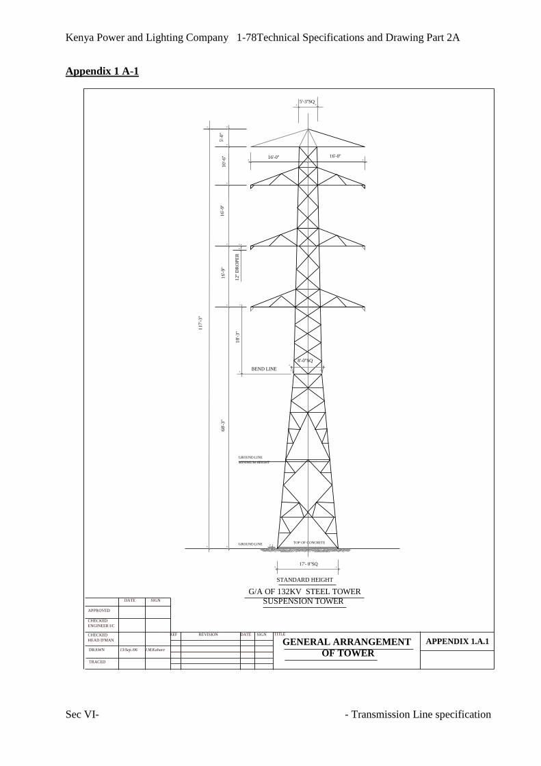
Kenya Power and Lighting Company 1-78Technical Specifications and Drawing Part 2A
Sec VI- - Transmission Line specification
Appendix 1 A-1
5'-3''SQ
16'-0''16'-0''
8'-0''SQ
18'-3''
68'-3''
16'-9''
16'-9''
10'-6''
5'-0''
117'-3''
BEND LINE
12''
DR
OP
ER
GROUND LINE
MINIMUM HEIGHT
17'- 0''SQ
GROUND LINE TOP OF CONCRETE
G/A OF 132KV STEEL TOWER
SUSPENSION TOWER
STANDARD HEIGHT
REF REVISION DATE SIGN
J.M.Kahare13/Sep./06
DATE SIGN
APPROVED
CHECKED
ENGINEER I/C
CHECKED
HEAD D'MAN
DRAWN
TRACED
TITLE
APPENDIX 1.A.1GENERAL ARRANGEMENT
OF TOWER

Kenya Power and Lighting Company 1-79Technical Specifications and Drawing Part 2A
Sec VI- - Transmission Line specification
Appendix 1 A-2
0
0
LENGTH OF INSULATOR SET
JUMPER
CJ FARANGE
0
0
0
0
SUSPENSION TOWER
CLEARANCE DIAGRAMS
TENSION TOWER
LOWEST PANEL OF TOWER
AND HILL SIDE EXTENSION
LEG AND STEP BOLTS
1.140
830
20
40
60
1.350
1.350
1.140
830
X
20
40
60
1.350
1.350
+3m
+2m
+1m
-1m
+- 0m A - LEG
STEP BOLT
B - LEG
(POWER STATION)
(SUBSTATION)
D - LEGC - LEG
STEP BOLT
REF REVISION DATE SIGN
J.M.Kahare13/Sep./06
DATE SIGN
APPROVED
CHECKED
ENGINEER I/C
CHECKED
HEAD D'MAN
DRAWN
TRACED
TITLE
APPENDIX 1.A.2CLEARANCE OF TOWER

Kenya Power and Lighting Company 1-80Technical Specifications and Drawing Part 2A
Sec VI- - Transmission Line specification
Appendix 1 A-3
REF REVISION DATE SIGN
J.M.Kahare
DATE SIGN APPROVED CHECKED ENGINEER I/C CHECKED HEAD D'MAN DRAWN
TRACED
TITLE APPENDIX 1.A.3
ANTI - CLIMBING DEVICE AND GROUNDING SYSTEM
19/Sep./06
GL
CLEATS ANNEALED COPPER WIRE STAND 22mm 1.0m IN LENGH
GALVANIZED STEEL ANGLE L 50 x 50 x 4, 1000mm IN LENGHT
CLEAT AND GROUNDING ANGLE
COUNTER WIRE GALVANIZED WIRE STRAND 38mm
GATE COUNTERPOISE WIRE
COUNTERPOISE WIRE
COUNTERPOISE WIRE
COUNTERPOISE WIRE
GALVANIZED IRON BARBED WIRE
TOWER LEG
ANTI - CLIMBING DEVICE
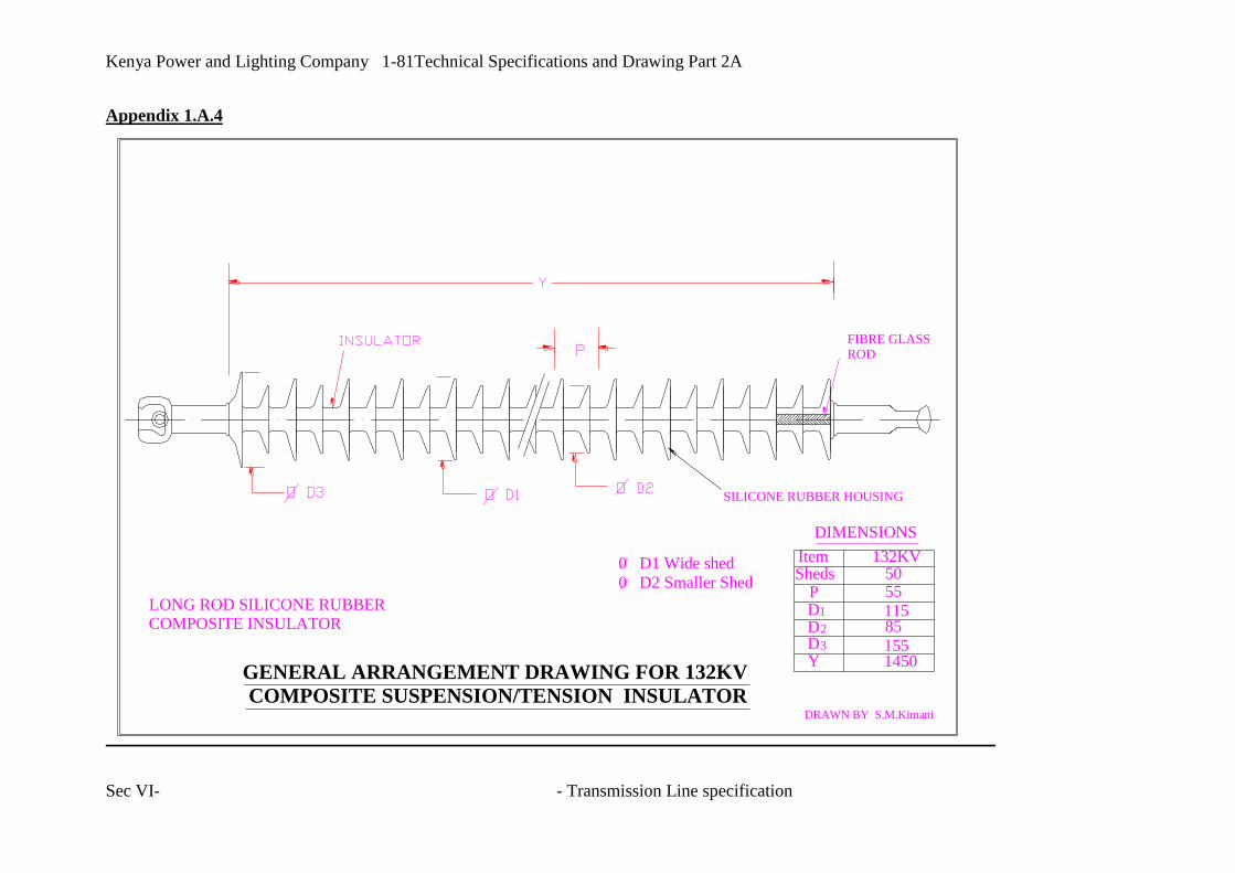
Kenya Power and Lighting Company 1-81Technical Specifications and Drawing Part 2A
Sec VI- - Transmission Line specification
Appendix 1.A.4
LONG ROD SILICONE RUBBERCOMPOSITE INSULATOR
DRAWN BY S.M.Kimani
GENERAL ARRANGEMENT DRAWING FOR 132KV
COMPOSITE SUSPENSION/TENSION INSULATOR
FIBRE GLASSROD
SILICONE RUBBER HOUSING
0 D1 Wide shed
0 D2 Smaller Shed
Item 132KVSheds
DP
1
D2
D3
Y
5055
115851551450
DIMENSIONS

Kenya Power and Lighting Company 1-82Technical Specifications and Drawing Part 2A
Sec VI- - Transmission Line specification
APPENDIX 1 A-5: ROUTE FOR PROPOSED BAMBURI 132/33KV – BAMBURI CEMENT LINE

Kenya Power and Lighting Company 1-83Technical Specifications and Drawing Part 2A
Sec VI- - Transmission Line specification

Kenya Power and Lighting Company 1-84Technical Specifications and Drawing Part 2A
Sec VI- - Transmission Line specification
13.2 SCHEDULE B- PLACES OF MANUFACTURE
MANUFACTUERS AND PLACES OF MANUFACTURE, TESTING, INSPECTIONS
AND SHIPMENT
Item Details Manufacturer Place of
Manufacture
Place of Testing
& Inspection
Port of
Shipment
1 Design of Towers
2 Steel Sections
3 Fabrication
4 Nuts & Bolts
5 Galvanising
6 Tower Tests
7 Composite Insulators
8 Compression Joints &
clamps
9 Insulator fittings
10 Aluminium wires
11 Steel core wires
12 Phase conductor
stranding
13 Optical Ground Wire
14 Vibration dampers
15 Jointing Compressors
Note: The words “or Similar” or “equivalent” etc. will not be accepted
In the event of award of contract no manufacturers or sub-contractors other than those named
above will be accepted by the Employer for the appropriate service or equipment.

Kenya Power and Lighting Company 1-85Technical Specifications and Drawing Part 2A
Sec VI- - Transmission Line specification
13.3 TECHNICAL PARTICULARS AND GUARANTEES-SCHEDULE C
C1-PHASE CONDUCTOR
Item Description Units Proposed
a
STRANDED CONDUCTORS
Type of Conductor- ACSR -
Code Name- LYNX -
Aluminium wire Nos./mm
Steel wire Nos./mm
Overall diameter mm
Cross-section of Aluminium area mm2
Cross-section of Steel area mm2
Weight per km kg
Calculated Breaking load kN
Maximum resistance at 20 deg. C per
km
ohm
Modulus of Elasticity kg/ mm2
Conductor lay -
Minimum weight of grease Kg/km
Length of conductor per drum m
Approximate net weight per drum kg
Approximate gross weight per drum kg
Dimension of drum ( diameter x
thickness)
mm x mm
b INDIVIDUAL WIRES BEFORE
STRANDING
Tolerance of diameter of Aluminium
wire
%
Tolerance of diameter of Steel wire %
Minimum tensile strength of
Aluminium wire
kg/ mm2

Kenya Power and Lighting Company 1-86Technical Specifications and Drawing Part 2A
Sec VI- - Transmission Line specification
Item Description Units Proposed
Minimum tensile strength of Steel
wire
kg/ mm2
Conductivity %
Minimum twisting number of steel
wire:
-100 x diameter ( length)
Nos.
Galvanising:
- Min. coating weight of Zinc
Grams/m2

Kenya Power and Lighting Company 1-87Technical Specifications and Drawing Part 2A
Sec VI- - Transmission Line specification
TECHNICAL PARTICULARS AND GUARANTEES FOR TRANSMISSION LINE
C2-CONDUCTOR ACCESSORIES
Item Description Units Proposed
2 CONDUCTOR ACESSORIES
a Tension Joint
Type- Compression -
Materials- Aluminium & steel -
Length mm
Ultimate breaking Load kg
b Vibration Dampers
Type- Stockbridge -
Weight kg
Galvanizing :
- Min. quantity coating
g/ m2
Galvanizing :
- Min. number of uniformity 1 minute
coating
times
c Preformed Armoured Rod
Number of individual wires Nos.
Diameter of individual wires mm
Length wires mm

Kenya Power and Lighting Company 1-88Technical Specifications and Drawing Part 2A
Sec VI- - Transmission Line specification
TECHNICAL PARTICULARS AND GUARANTEES FOR TRANSMISSION LINE
C3-CONDUCTOR FITTINGS
Description Units Proposed
FITTINGS Suspension Tension
a Clamp for Conductor
Type Trunnion Compression
Material of clamp
Length of clamp mm
Ultimate breaking Load kg
Approx. slipping Load kg
b Clamp for Earthwire Trunnion Bolted or
Compression
Type
Material of clamp mm
Length of clamp kg
Ultimate breaking Load kg
Approx. slipping Load kg

Kenya Power and Lighting Company 1-89Technical Specifications and Drawing Part 2A
Sec VI- - Transmission Line specification
TECHNICAL PARTICULARS AND GUARANTEES FOR TRANSMISSION LINE
C4-INSULATOR UNITS & ACCESSORIES
Description Units Proposed
Suspension Tension
1 Maximum System
Voltage
kV
2 Pollution Category class
3 Dielectric
4 One-minute power
frequency withstand
voltage, 50 Hz, wet.
kV
5 Lighting impulse
withstand voltage, 1,2/50
pos.
kV
6 Power arc current kA, 0.5sec
7 Minimum creepage
distance
mm
8 Specified mechanical
load,
KN
9 Minimum Arc Gap mm
10 Material fittings
11 Material of rod
12 Material of housing and
sheds
13 Socket IEC
standard
14 Ball IEC
Standard
15 Arcing Rings material
16 Arcing rings IEC
Standard

Kenya Power and Lighting Company 1-90Technical Specifications and Drawing Part 2A
Sec VI- - Transmission Line specification
TECHNICAL PARTICULARS AND GUARANTEES FOR TRANSMISSION LINE
C5-OPGW
Type:
Item Particulars Unit Employer's
requirement
Tender
value
1 OPGW
2 Number of fibres > 48
3
Core diameter µm 8.3 or 9 with
a 3%
tolerance
4 Cladding design, either matched or depressed
5 Clad diameter µm 125.0 + 2
6 Core-clad concentricity < 2%
7 Coating diameter µm 250.0 + 15
8 Coating concentricity > 0.70
9 Attenuation: 1310 nm
1550 nm
dB/km < 0.40
< 0.25
10 Bending attenuation: 1310 nm
1550 nm
dB/km < 0.40
< 0.25
11
Temperature dependence dB/km <0.05 (-
20°C-
+85°C)
12 Cut-off wavelength Nm < 1250
13 Chromatic dispersion:
Zero dispersion at Nm 1310 + 12
1550 + 15
Zero dispersion slope (max.) ps/nm^2
(km)
0.092
0.085
Zero dispersion slope (max.) ps/nm^2
(km)
0.092
0.085
14
Mode field diameter:
1300 nm mm 9.30 + 0.50
1550 nm mm 10.50 + 1.00
15 IL-proof test level g/m2 35 x 106

Kenya Power and Lighting Company 1-91Technical Specifications and Drawing Part 2A
Sec VI- - Transmission Line specification
16 Splice attenuation dB/
splice
0.02
17 Connector loss dB/connector < 0.5
ODF
Manufacturer -
Type -
Number of fiber interconnections - 96
Connector loss dB/connector < 0.5
Screw on type connectors - yes
designed for 19” cubicles - yes
- -

Kenya Power and Lighting Company 1-92Technical Specifications and Drawing Part 2A
Sec VI- - Transmission Line specification
SCHEDULE C: TECHNICAL PARTICULARS AND GUARANTEES FOR TRANSMISSION LINE
C6. TOWERS & FOUNDATIONS
Item Particulars Unit Type-S Type-L Type-M Type-H Type –HS Type-T
5.1
DIMENSIONS AND WEIGHT OF
TOWER
Overall height of standard tower (+0m) m
Length of top conductor cross-arm m
Length of bottom conductor cross-arm m
Vertical spacing of conductor:
Ground wire and top conductor
Top conductor and bottom conductors
m
m
Width of tower body at:
Top of tower
Lowest cross-arm
Ground level of standard tower (+0m)
m
m
m
Weight of towers
-3m body extension
+0m body extension
+3m body extension
+6m body extension
kg
kg
kg
kg

Kenya Power and Lighting Company 1-93Technical Specifications and Drawing Part 2A
Sec VI- - Transmission Line specification
Item Particulars Unit Type-S Type-L Type-M Type-H Type –HS Type-T
5.2
5.2.1
5.2.2
LOAD ON FOUNDATION FROM
TOWERS
Compression Load
-3m body extension
+0m body extension
+3m body extension
+6m body extension
kg
kg
kg
kg
Uplifting Load
-3m body extension
+0m body extension
+3m body extension
+6m body extension
kg
kg
kg
kg
5.3
5.3.1 5.3
5.3.2
CONCRETE PAD FOUNDATION AND
STUB LENGTH
Depth of Foundations
-3m body extension
+0m body extension
+3m body extension
+6m body extension
mm
mm
mm
mm

Kenya Power and Lighting Company 1-94Technical Specifications and Drawing Part 2A
Sec VI- - Transmission Line specification
Item Particulars Unit Type-S Type-L Type-M Type-H Type –HS Type-T
5.3.3
5.3.4
5.3.5
Width of Base Pad
-3m body extension
+0m body extension
+3m body extension
+6m body extension
mm
mm
mm
mm
Thickness of Base Pad
-3m body extension
+0m body extension
+3m body extension
+6m body extension
mm
mm
mm
mm
Top Width of Chimney
-3m body extension
+0m body extension
+3m body extension
+6m body extension
mm
mm
mm
mm
Bottom Width of Chimney
-3m body extension
+0m body extension
+3m body extension
+6m body extension
mm
mm
mm
mm
Volume of Excavation

Kenya Power and Lighting Company 1-95Technical Specifications and Drawing Part 2A
Sec VI- - Transmission Line specification
Item Particulars Unit Type-S Type-L Type-M Type-H Type –HS Type-T
-3m body extension
+0m body extension
+3m body extension
+6m body extension
cu. m
cu. m
cu. m
cu. m
Volume of Concrete
-3m body extension
+0m body extension
+3m body extension
+6m body extension
cu. m
cu. m
cu. m
cu. m
Length of Stubs: (stub length x cleat)
-3m body extension
+0m body extension
+3m body extension
+6m body extension
mm
mm
mm
mm

Kenya Power and Lighting Company 1-96Technical Specifications and Drawing Part 2A
Sec VI- - Transmission Line specification

Kenya Power and Lighting Company 1-97Technical Specifications and Drawing Part 2A
Sec VI- - Transmission Line specification