Embed Size (px)
Citation preview
Part 3 in a Three-Part Series
The Model T Ignition CoilPart 3: Chronology of the Ford/K-W Coil Unit
By Trent E. Boggess and Ronald Patterson
“Specified the name FORD to be burned in script on the side of box.”Joseph Galamb, “Record of Changes for T-5845 Coil Unit Assembly,” March 19, 1919
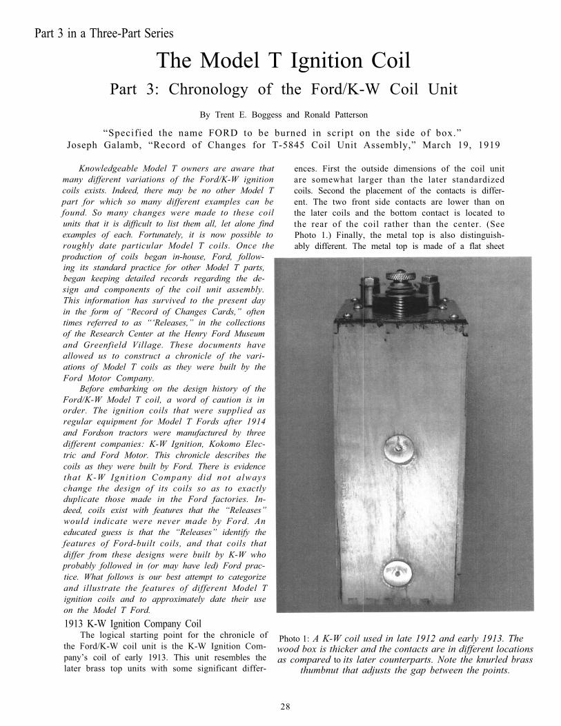
Knowledgeable Model T owners are aware thatmany different variations of the Ford/K-W ignitioncoils exists. Indeed, there may be no other Model Tpart for which so many different examples can befound. So many changes were made to these coilunits that it is difficult to list them all, let alone findexamples of each. Fortunately, it is now possible toroughly date particular Model T coils. Once theproduction of coils began in-house, Ford, follow-ing its standard practice for other Model T parts,began keeping detailed records regarding the de-sign and components of the coil unit assembly.This information has survived to the present dayin the form of “Record of Changes Cards,” oftentimes referred to as “‘Releases,” in the collectionsof the Research Center at the Henry Ford Museumand Greenfield Village. These documents haveallowed us to construct a chronicle of the vari-ations of Model T coils as they were built by theFord Motor Company.
ences. First the outside dimensions of the coil unitare somewhat larger than the later standardizedcoils. Second the placement of the contacts is differ-ent. The two front side contacts are lower than onthe later coils and the bottom contact is located tothe rear of the coil rather than the center. (SeePhoto 1.) Finally, the metal top is also distinguish-ably different. The metal top is made of a flat sheet
Before embarking on the design history of theFord/K-W Model T coil, a word of caution is inorder. The ignition coils that were supplied asregular equipment for Model T Fords after 1914and Fordson tractors were manufactured by threedifferent companies: K-W Ignition, Kokomo Elec-tric and Ford Motor. This chronicle describes thecoils as they were built by Ford. There is evidencethat K-W Igni t ion Company did not alwayschange the design of its coils so as to exactlyduplicate those made in the Ford factories. In-deed, coils exist with features that the “Releases”would indicate were never made by Ford. Aneducated guess is that the “Releases” identify thefeatures of Ford-built coils, and that coils thatdiffer from these designs were built by K-W whoprobably followed in (or may have led) Ford prac-tice. What follows is our best attempt to categorizeand illustrate the features of different Model Tignition coils and to approximately date their useon the Model T Ford.1913 K-W Ignition Company Coil
The logical starting point for the chronicle ofthe Ford/K-W coil unit is the K-W Ignition Com-
Photo 1: A K-W coil used in late 1912 and early 1913. Thewood box is thicker and the contacts are in different locations
pany’s coil of early 1913. This unit resembles thelater brass top units with some significant differ-
as compared to its later counterparts. Note the knurled brassthumbnut that adjusts the gap between the points.
28
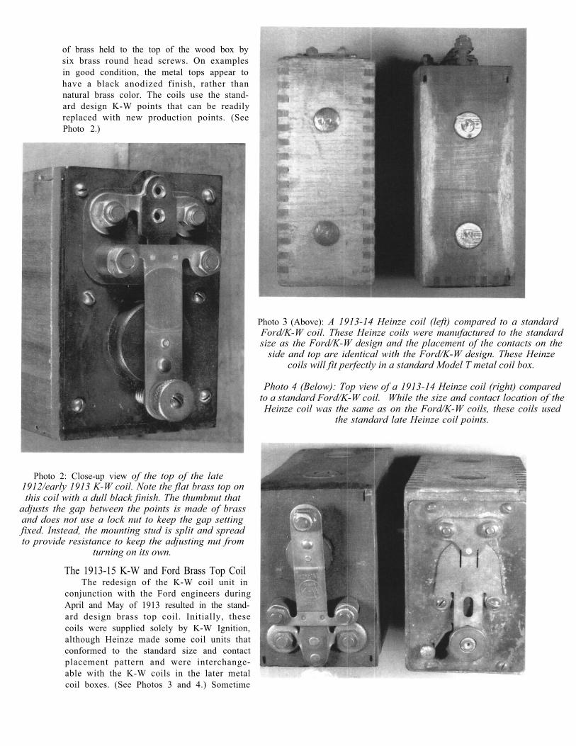
of brass held to the top of the wood box bysix brass round head screws. On examplesin good condition, the metal tops appear tohave a black anodized finish, rather thannatural brass color. The coils use the stand-ard design K-W points that can be readilyreplaced with new production points. (SeePhoto 2.)
Photo 3 (Above): A 1913-14 Heinze coil (left) compared to a standardFord/K-W coil. These Heinze coils were manufactured to the standardsize as the Ford/K-W design and the placement of the contacts on the
side and top are identical with the Ford/K-W design. These Heinzecoils will fit perfectly in a standard Model T metal coil box.
Photo 4 (Below): Top view of a 1913-14 Heinze coil (right) comparedto a standard Ford/K-W coil. While the size and contact location of theHeinze coil was the same as on the Ford/K-W coils, these coils used
the standard late Heinze coil points.
Photo 2: Close-up view of the top of the late1912/early 1913 K-W coil. Note the flat brass top onthis coil with a dull black finish. The thumbnut that
adjusts the gap between the points is made of brassand does not use a lock nut to keep the gap settingfixed. Instead, the mounting stud is split and spreadto provide resistance to keep the adjusting nut from
turning on its own.
The 1913-15 K-W and Ford Brass Top CoilThe redesign of the K-W coil unit in
conjunction with the Ford engineers duringApril and May of 1913 resulted in the stand-ard design brass top coil. Initially, thesecoils were supplied solely by K-W Ignition,although Heinze made some coil units thatconformed to the standard size and contactplacement pattern and were interchange-able with the K-W coils in the later metalcoil boxes. (See Photos 3 and 4.) Sometime
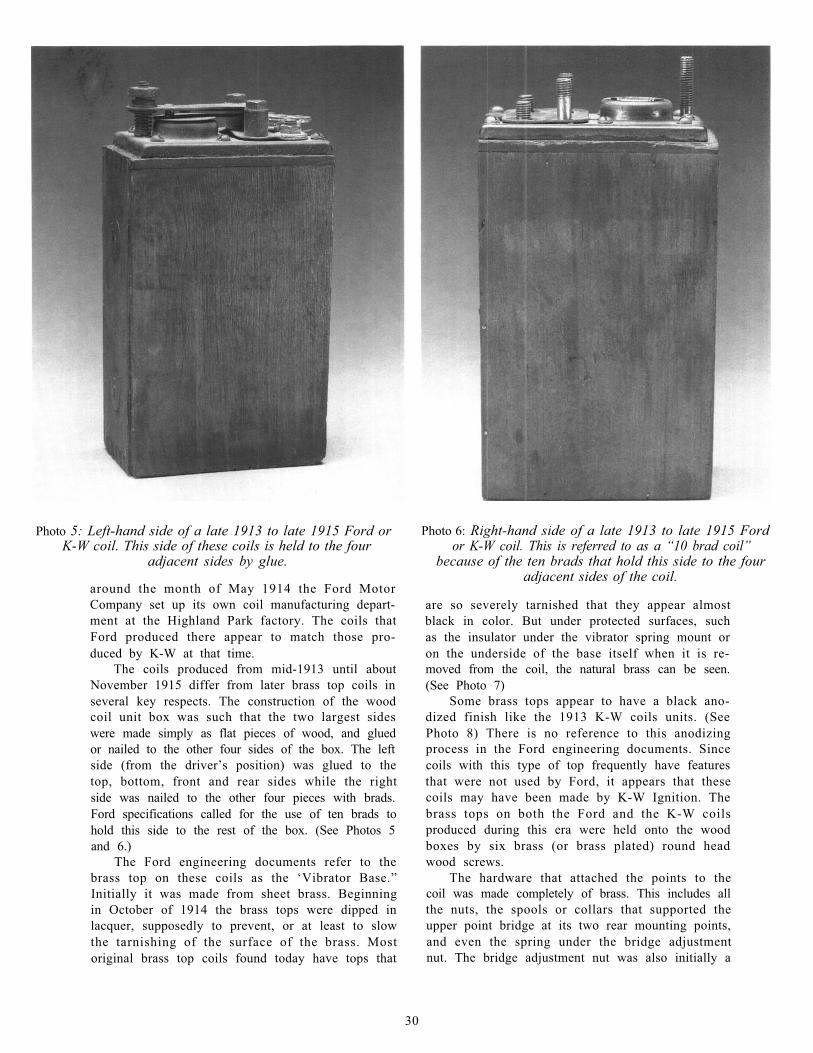
Photo 5: Left-hand side of a late 1913 to late 1915 Ford orK-W coil. This side of these coils is held to the four
adjacent sides by glue.
around the month of May 1914 the Ford MotorCompany set up its own coil manufacturing depart-ment at the Highland Park factory. The coils thatFord produced there appear to match those pro-duced by K-W at that time.
The coils produced from mid-1913 until aboutNovember 1915 differ from later brass top coils inseveral key respects. The construction of the woodcoil unit box was such that the two largest sideswere made simply as flat pieces of wood, and gluedor nailed to the other four sides of the box. The leftside (from the driver’s position) was glued to thetop, bottom, front and rear sides while the rightside was nailed to the other four pieces with brads.Ford specifications called for the use of ten brads tohold this side to the rest of the box. (See Photos 5and 6.)
The Ford engineering documents refer to thebrass top on these coils as the ‘Vibrator Base.”Initially it was made from sheet brass. Beginningin October of 1914 the brass tops were dipped inlacquer, supposedly to prevent, or at least to slowthe tarnishing of the surface of the brass. Mostoriginal brass top coils found today have tops that
Photo 6: Right-hand side of a late 1913 to late 1915 Fordor K-W coil. This is referred to as a “10 brad coil”
because of the ten brads that hold this side to the fouradjacent sides of the coil.
are so severely tarnished that they appear almostblack in color. But under protected surfaces, suchas the insulator under the vibrator spring mount oron the underside of the base itself when it is re-moved from the coil, the natural brass can be seen.(See Photo 7)
Some brass tops appear to have a black ano-dized finish like the 1913 K-W coils units. (SeePhoto 8) There is no reference to this anodizingprocess in the Ford engineering documents. Sincecoils with this type of top frequently have featuresthat were not used by Ford, it appears that thesecoils may have been made by K-W Ignition. Thebrass tops on both the Ford and the K-W coilsproduced during this era were held onto the woodboxes by six brass (or brass plated) round headwood screws.
The hardware that attached the points to thecoil was made completely of brass. This includes allthe nuts, the spools or collars that supported theupper point bridge at its two rear mounting points,and even the spring under the bridge adjustmentnut. The bridge adjustment nut was also initially a
30
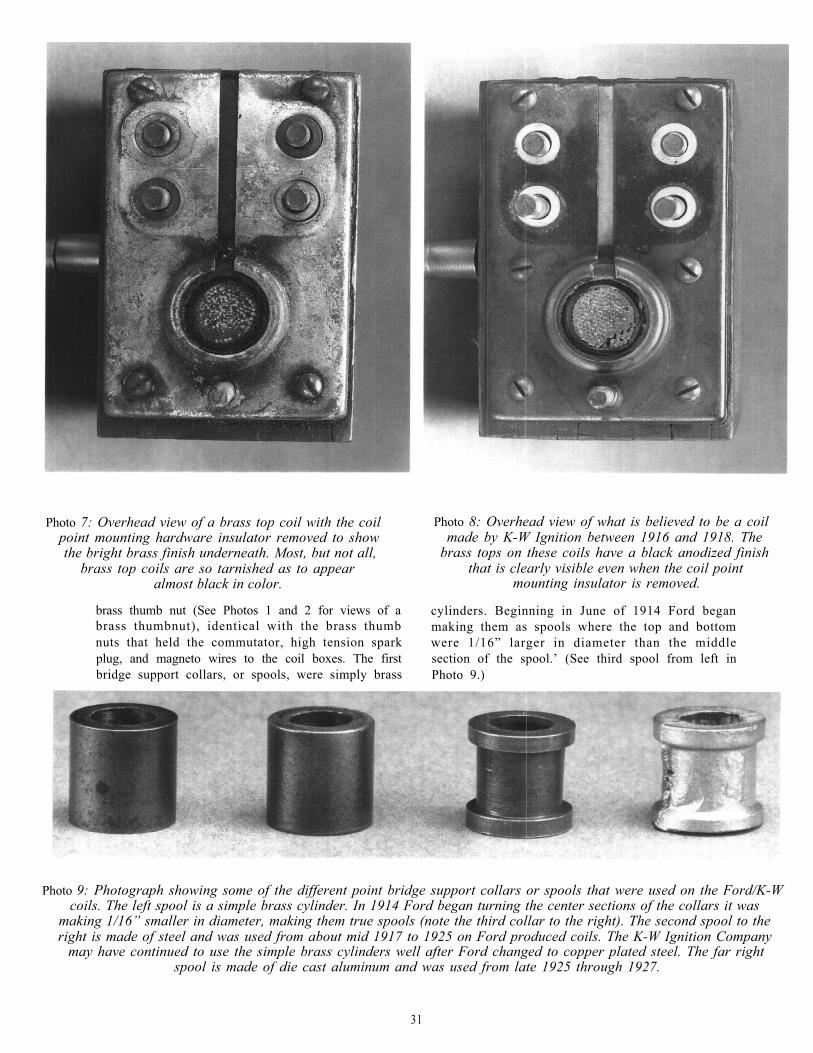
Photo 7: Overhead view of a brass top coil with the coilpoint mounting hardware insulator removed to showthe bright brass finish underneath. Most, but not all,
brass top coils are so tarnished as to appearalmost black in color.
brass thumb nut (See Photos 1 and 2 for views of abrass thumbnut), identical with the brass thumbnuts that held the commutator, high tension sparkplug, and magneto wires to the coil boxes. The firstbridge support collars, or spools, were simply brass
Photo 8: Overhead view of what is believed to be a coilmade by K-W Ignition between 1916 and 1918. The
brass tops on these coils have a black anodized finishthat is clearly visible even when the coil point
mounting insulator is removed.
cylinders. Beginning in June of 1914 Ford beganmaking them as spools where the top and bottomwere 1/16” larger in diameter than the middlesection of the spool.’ (See third spool from left inPhoto 9.)
Photo 9: Photograph showing some of the different point bridge support collars or spools that were used on the Ford/K-Wcoils. The left spool is a simple brass cylinder. In 1914 Ford began turning the center sections of the collars it was
making 1/16” smaller in diameter, making them true spools (note the third collar to the right). The second spool to theright is made of steel and was used from about mid 1917 to 1925 on Ford produced coils. The K-W Ignition Company
may have continued to use the simple brass cylinders well after Ford changed to copper plated steel. The far rightspool is made of die cast aluminum and was used from late 1925 through 1927.
31
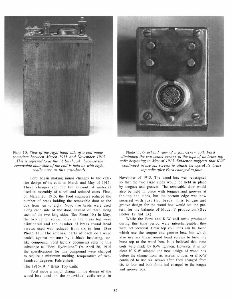
Photo 10: View of the right-hand side of a coil madesometime between March 1915 and November 1915.
This is referred to as the “8 brad coil” because theremovable door side of the coil is held on with eight,
really nine in this case-brads.
Ford began making minor changes to the exte-rior design of its coils in March and May of 1915.These changes reduced the amount of materialused in assembly of a coil and reduced costs. First,on March 20, 1915, the Ford engineers reduced thenumber of brads holding the removable door to thebox from ten to eight. Now, two brads were usedalong each side of the door, instead of three alongeach of the two long sides. (See Photo 10.) In May,the two center screw holes in the brass top wereeliminated and the number of brass round headscrews used was reduced from six to four. (SeePhoto 11.) The internal parts of each coil weresealed against moisture by a black insulating, tar-like compound. Ford factory documents refer to thissubstance as “Ford Hydrolene.” On April 26, 1915the specifications for this compound were changedto require a minimum melting temperature of two-hundred degrees Fahrenheit.The 1916-1917 Brass Top Coils
Ford made a major change in the design of thewood box used on the individual coils units in
Photo 11: Overhead view of a four-screw coil. Fordeliminated the two center screws in the tops of its brass topcoils beginning in May of 1915. Evidence suggests that K-W
continued to use six screws to attach the tops of its brasstop coils after Ford changed to four.
November of 1915. The wood box was redesignedso that the two large sides would be held in placeby tongues and grooves. The removable door wouldalso be held in place with tongues and grooves atthe top and sides, but the bottom edge was nowsecured with just two brads. This tongue andgroove design for the wood box would set the pat-tern for the balance of Model T production.3 (SeePhotos 12 and 13.)
While the Ford and K-W coil units producedduring this time period were interchangeable, theywere not identical. Brass top coil units can be foundwhich use the tongue and groove box, but whichalso use six brass round head screws to hold thebrass top to the wood box. It is believed that thesecoils were made by K-W Ignition. However, it is notclear if K-W adopted the new design of wood boxbefore the change from six screws to four, or if K-Wcontinued to use six screws after Ford changed fromsix to four and both firms had changed to the tongueand groove box.
32
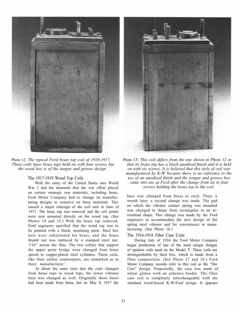
Photo 12: The typical Ford brass top coil of 1916-1917.These coils have brass tops held on with four screws but
the wood box is of the tongue and groove design.
The 1917-1919 Wood Top CoilsWith the entry of the United States into World
War I and the demands that the war effort placedon certain strategic raw materials, including brass,Ford Motor Company had to change its manufac-turing designs to conserve on these materials. Thiscaused a major redesign of the coil unit in June of1917. The brass top was removed and the coil pointswere now mounted directly on the wood top. (SeePhotos 14 and 15.) With the brass top removed,Ford engineers specified that the wood top was tobe painted with a black, insulating paint. Steel hexnuts were substi tuted for brass, and the brassthumb nut was replaced by a stamped steel nut,7/16” across the flats. The two collars that supportthe upper point bridge were changed from brassspools to copper-plated steel cylinders. These coils,like their earlier counterparts, are unmarked as totheir manufacturer.4
At about the same time that the coils changedfrom brass tops to wood tops, the lower vibratorbase was changed as well. Originally these baseshad been made from brass, but on May 8, 1917 the
Photo 13: This coil differs from the one shown in Photo 12 inthat its brass top has a black anodized finish and it is heldon with six screws. It is believed that this style of coil was
manufactured by K-W because there is no reference to theuse of an anodized finish and the tongue and groove box
came into use at Ford after the change from six to fourscrews holding the brass top to the coil.
base was changed from brass to steel. Then, amonth later, a second change was made. The padon which the vibrator contact spring was mountedwas changed in shape from rectangular to an ar-rowhead shape. This change was made by the Fordengineers to accommodate the new design of thespring steel vibrator and for convenience in manu-facturing. (See Photo 16.)The 1916-1918 Fiber Case Coils
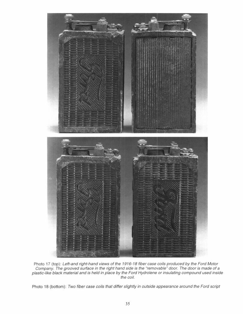
During July of 1916 the Ford Motor Companybegan production of one of the most unique designsof ignition coils used on the Model T. These coils aredistinguishable by their box, which is made from afiber composition. (See Photo 17 and 18.) FordMotor Company records refer to this coil as the “DieCast” design. Purportedly, the case was made ofwheat gluten with an asbestos binder. The fibercase coil is completely interchangeable with thestandard wood-boxed K-W/Ford design. It appears
33
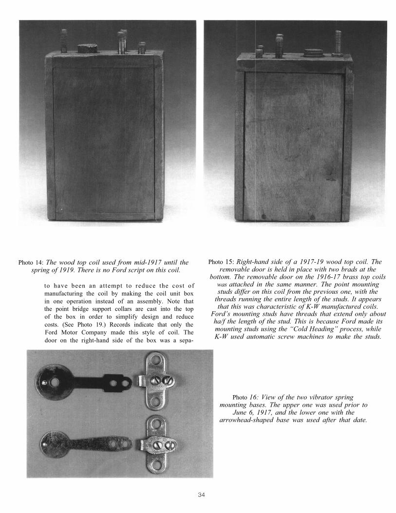
Photo 14: The wood top coil used from mid-1917 until thespring of 1919. There is no Ford script on this coil.
to have been an attempt to reduce the cost ofmanufacturing the coil by making the coil unit boxin one operation instead of an assembly. Note thatthe point bridge support collars are cast into the topof the box in order to simplify design and reducecosts. (See Photo 19.) Records indicate that only theFord Motor Company made this style of coil. Thedoor on the right-hand side of the box was a sepa-
Photo 15: Right-hand side of a 1917-19 wood top coil. Theremovable door is held in place with two brads at the
bottom. The removable door on the 1916-17 brass top coilswas attached in the same manner. The point mountingstuds differ on this coil from the previous one, with the
threads running the entire length of the studs. It appearsthat this was characteristic of K-W manufactured coils.
Ford’s mounting studs have threads that extend only aboutha/f the length of the stud. This is because Ford made itsmounting studs using the “Cold Heading” process, whileK-W used automatic screw machines to make the studs.
Photo 16: View of the two vibrator springmounting bases. The upper one was used prior to
June 6, 1917, and the lower one with thearrowhead-shaped base was used after that date.
35
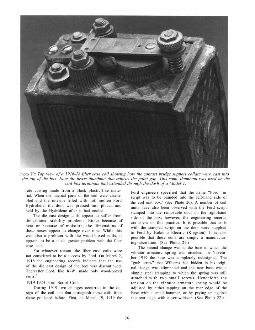
Photo 19: Top view of a 1916-18 fiber case coil showing how the contact bridge support collars were cast intothe top of the box. Note the brass thumbnut that adjusts the point gap. This same thumbnut was used on the
coil box terminals that extended through the dash of a Model T.rate casting made from a black plastic-like mate-rial. When the internal parts of the coil were assem-bled and the interior filled with hot, molten FordHydrolene, the door was pressed into placed andheld by the Hydrolene after it had cooled.
The die cast design coils appear to suffer fromdimensional stability problems. Either because ofheat or because of moisture, the dimensions ofthese boxes appear to change over time. While thiswas also a problem with the wood-boxed coils, itappears to be a much greater problem with the fibercase coils.
For whatever reason, the fiber case coils werenot considered to be a success by Ford. On March 2,1918 the engineering records indicate that the useof the die cast design of the box was discontinued.Thereafter Ford, like K-W, made only wood-boxedcoils.5
1919-1923 Ford Script CoilsDuring 1919 two changes occurred in the de-
sign of the coil unit that distinguish these coils fromthose produced before. First, on March 19, 1919 the
Ford engineers specified that the name “Ford” inscript was to be branded into the left-hand side ofthe coil unit box.’ (See Photo 20). A number of coilunits have also been observed with the Ford scriptstamped into the removable door on the right-handside of the box; however, the engineering recordsare silent on this practice. It is possible that coilswith the stamped script on the door were suppliedto Ford by Kokomo Electric (Kingston). It is alsopossible that these coils are simply a manufactur-ing aberration. (See Photo 21.)
The second change was to the base to which thevibrator armature spring was attached. In Novem-ber 1919 the base was completely redesigned. The“grub screw” that Williams had hidden in his origi-nal design was eliminated and the new base was asimple steel stamping to which the spring was stillattached with two small screws. Henceforth thetension on the vibrator armature spring would beadjusted by either tapping on the rear edge of thebase with a small hammer, or by prying up againstthe rear edge with a screwdriver. (See Photo 22.)
36
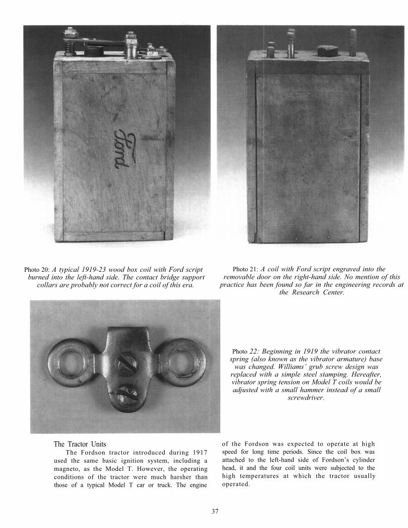
Photo 20: A typical 1919-23 wood box coil with Ford scriptburned into the left-hand side. The contact bridge support
collars are probably not correct for a coil of this era.
Photo 21: A coil with Ford script engraved into theremovable door on the right-hand side. No mention of this
practice has been found so far in the engineering records atthe Research Center.
Photo 22: Beginning in 1919 the vibrator contactspring (also known as the vibrator armature) base
was changed. Williams’ grub screw design wasreplaced with a simple steel stamping. Hereafter,vibrator spring tension on Model T coils would beadjusted with a small hammer instead of a small
screwdriver.
The Tractor Units of the Fordson was expected to operate at highThe Fordson tractor introduced during 1917 speed for long time periods. Since the coil box was
used the same basic ignition system, including a attached to the left-hand side of Fordson’s cylindermagneto, as the Model T. However, the operating head, it and the four coil units were subjected to theconditions of the tractor were much harsher than high temperatures at which the tractor usuallythose of a typical Model T car or truck. The engine operated.
37
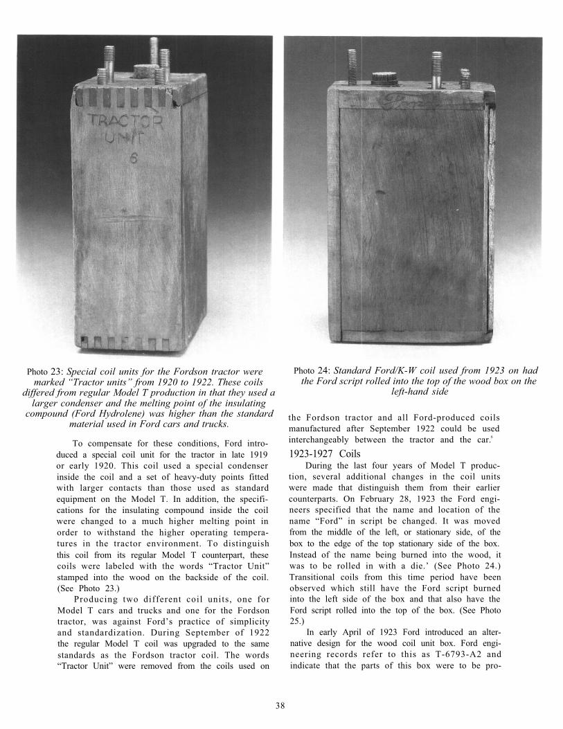
Photo 23: Special coil units for the Fordson tractor weremarked “Tractor units” from 1920 to 1922. These coils
differed from regular Model T production in that they used alarger condenser and the melting point of the insulating
compound (Ford Hydrolene) was higher than the standardmaterial used in Ford cars and trucks.
To compensate for these conditions, Ford intro-duced a special coil unit for the tractor in late 1919or early 1920. This coil used a special condenserinside the coil and a set of heavy-duty points fittedwith larger contacts than those used as standardequipment on the Model T. In addition, the specifi-cations for the insulating compound inside the coilwere changed to a much higher melting point inorder to withstand the higher operating tempera-tures in the tractor environment. To distinguishthis coil from its regular Model T counterpart, thesecoils were labeled with the words “Tractor Unit”stamped into the wood on the backside of the coil.(See Photo 23.)
Producing two different coil units, one forModel T cars and trucks and one for the Fordsontractor, was against Ford’s practice of simplicityand standardization. During September of 1922the regular Model T coil was upgraded to the samestandards as the Fordson tractor coil. The words“Tractor Unit” were removed from the coils used on
Photo 24: Standard Ford/K-W coil used from 1923 on hadthe Ford script rolled into the top of the wood box on the
left-hand side
the Fordson tractor and all Ford-produced coilsmanufactured after September 1922 could be usedinterchangeably between the tractor and the car.6
1923-1927 CoilsDuring the last four years of Model T produc-
tion, several additional changes in the coil unitswere made that distinguish them from their earliercounterparts. On February 28, 1923 the Ford engi-neers specified that the name and location of thename “Ford” in script be changed. It was movedfrom the middle of the left, or stationary side, of thebox to the edge of the top stationary side of the box.Instead of the name being burned into the wood, itwas to be rolled in with a die.’ (See Photo 24.)Transitional coils from this time period have beenobserved which still have the Ford script burnedinto the left side of the box and that also have theFord script rolled into the top of the box. (See Photo25.)
In early April of 1923 Ford introduced an alter-native design for the wood coil unit box. Ford engi-neering records refer to this as T-6793-A2 andindicate that the parts of this box were to be pro-
38
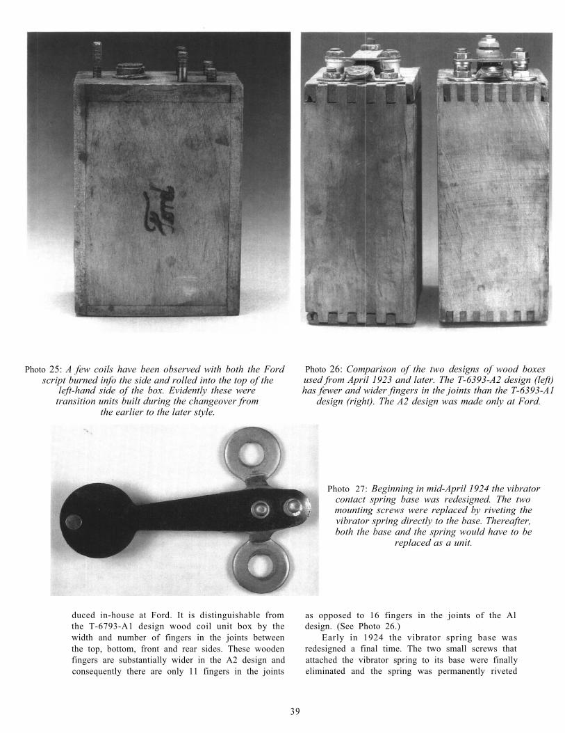
Photo 25: A few coils have been observed with both the Fordscript burned info the side and rolled into the top of the
left-hand side of the box. Evidently these weretransition units built during the changeover from
the earlier to the later style.
Photo 26: Comparison of the two designs of wood boxesused from April 1923 and later. The T-6393-A2 design (left)has fewer and wider fingers in the joints than the T-6393-A1
design (right). The A2 design was made only at Ford.
Photo 27: Beginning in mid-April 1924 the vibratorcontact spring base was redesigned. The twomounting screws were replaced by riveting thevibrator spring directly to the base. Thereafter,both the base and the spring would have to be
replaced as a unit.
duced in-house at Ford. It is distinguishable from as opposed to 16 fingers in the joints of the Althe T-6793-A1 design wood coil unit box by the design. (See Photo 26.)width and number of fingers in the joints between Early in 1924 the vibrator spring base wasthe top, bottom, front and rear sides. These wooden redesigned a final time. The two small screws thatfingers are substantially wider in the A2 design and attached the vibrator spring to its base were finallyconsequently there are only 11 fingers in the joints eliminated and the spring was permanently riveted
39
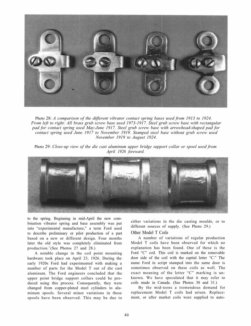
Photo 28: A comparison of the different vibrator contact spring bases used from 1913 to 1924.From left to right: All brass grub screw base used 1973-1917. Steel grub screw base with rectangularpad for contact spring used May-June 1917. Steel grub screw base with arrowhead-shaped pad for
contact spring used June 1917 to November 1919. Stamped steel base without grub screw usedNovember 1919 to August 1924.
Photo 29: Close-up view of the die cast aluminum upper bridge support collar or spool used fromApril 1926 foreward.
to the spring. Beginning in mid-April the new com-bination vibrator spring and base assembly was putinto “experimental manufacture,” a term Ford usedto describe preliminary or pilot production of a partbased on a new or different design. Four monthslater the old style was completely eliminated fromproduction.9 (See Photos 27 and 28.)
A notable change in the coil point mountinghardware took place on April 23, 1926. During theearly 1920s Ford had experimented with making anumber of parts for the Model T out of die castaluminum. The Ford engineers concluded that theupper point bridge support collars could be pro-duced using this process. Consequently, they werechanged from copper-plated steel cylinders to alu-minum spools. Several minor variations in thesespools have been observed. This may be due to
either variations in the die casting moulds, or todifferent sources of supply. (See Photo 29.)Other Model T Coils
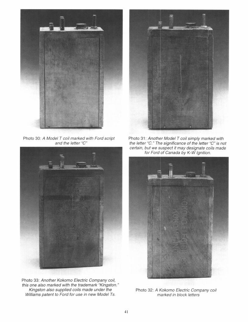
A number of variations of regular productionModel T coils have been observed for which noexplanation has been found. One of these is theFord “C” coil. This coil is marked on the removabledoor side of the coil with the capital letter “C.” Thename Ford in script stamped into the same door issometimes observed on these coils as well. Theexact meaning of the letter “C” marking is un-known. We have speculated that it may refer tocoils made in Canada. (See Photos 30 and 31.)
By the mid-teens a tremendous demand forreplacement Model T coils had arisen. Replace-ment, or after market coils were supplied to auto-
40
41
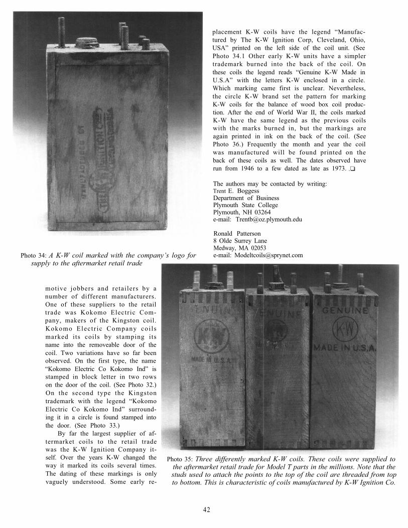
Photo 34: A K-W coil marked with the company’s logo forsupply to the aftermarket retail trade
motive jobbers and retailers by anumber of different manufacturers.One of these suppliers to the retailtrade was Kokomo Electric Com-pany, makers of the Kingston coil.Kokomo Elec t r ic Company co i l smarked its coils by stamping itsname into the removeable door of thecoil. Two variations have so far beenobserved. On the first type, the name“Kokomo Electric Co Kokomo Ind” isstamped in block letter in two rowson the door of the coil. (See Photo 32.)On the second type the Kingstontrademark with the legend “KokomoElectric Co Kokomo Ind” surround-ing it in a circle is found stamped intothe door. (See Photo 33.)
By far the largest supplier of af-termarket coils to the retail tradewas the K-W Ignition Company it-self. Over the years K-W changed theway it marked its coils several times.The dating of these markings is onlyvaguely understood. Some early re-
placement K-W coils have the legend “Manufac-tured by The K-W Ignition Corp, Cleveland, Ohio,USA” printed on the left side of the coil unit. (SeePhoto 34.1 Other early K-W units have a simplertrademark burned into the back of the coil. Onthese coils the legend reads “Genuine K-W Made inU.S.A” with the letters K-W enclosed in a circle.Which marking came first is unclear. Nevertheless,the circle K-W brand set the pattern for markingK-W coils for the balance of wood box coil produc-tion. After the end of World War II, the coils markedK-W have the same legend as the previous coilswith the marks burned in, but the markings areagain printed in ink on the back of the coil. (SeePhoto 36.) Frequently the month and year the coilwas manufactured will be found printed on theback of these coils as well. The dates observed haverun from 1946 to a few dated as late as 1973.
The authors may be contacted by writing:Trent E. BoggessDepartment of BusinessPlymouth State CollegePlymouth, NH 03264e-mail: [email protected]
Ronald Patterson8 Olde Surrey LaneMedway, MA 02053e-mail: [email protected]
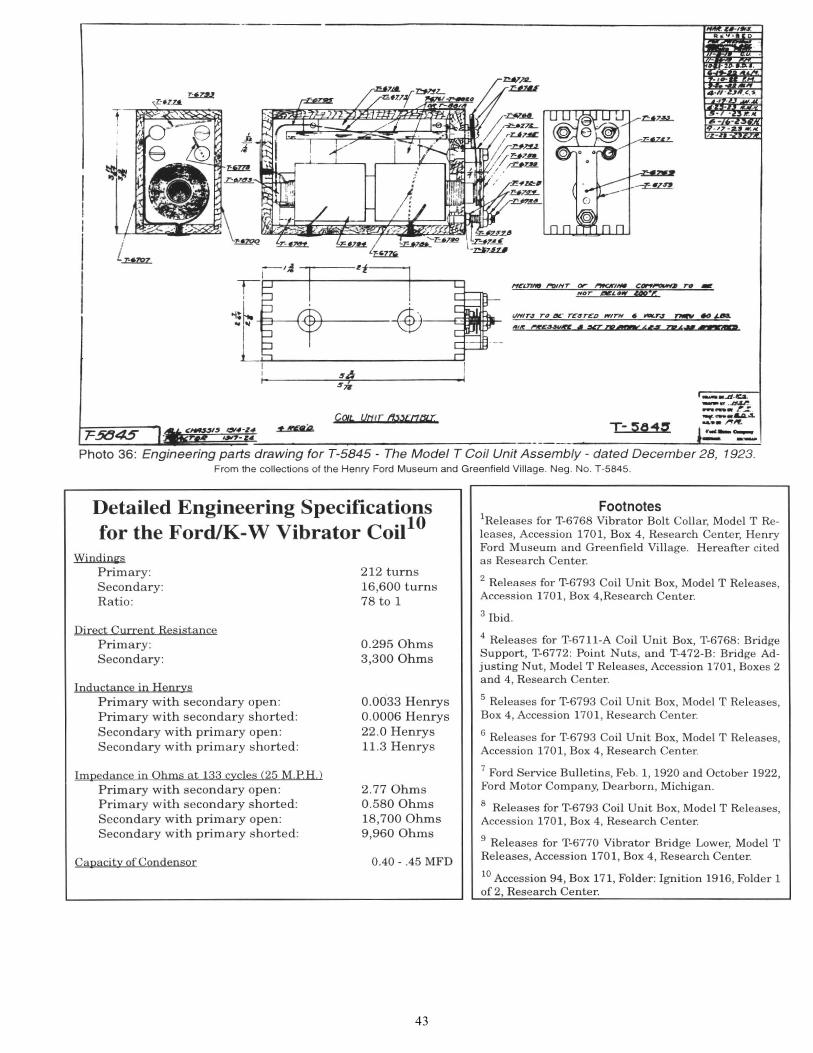
Photo 35: Three differently marked K-W coils. These coils were supplied tothe aftermarket retail trade for Model T parts in the millions. Note that thestuds used to attach the points to the top of the coil are threaded from topto bottom. This is characteristic of coils manufactured by K-W Ignition Co.
42
43