Embed Size (px)
Citation preview

PART 4
LOW PRESSURE BOILERS
(Statutory authority: Labor Law, §§27-a, 27, 29, 200, 204)
Subpart 4-1 General Provisions
4-1.1 Title and citation 4-1.2 Definitions 4-1.3 Application 4-1.4 Purpose and intent 4-1.5 Construction of provisions 4-1.6 Severability 4-1.7 Prohibited installation 4-1.8 Prohibited operation 4-1.9 Standard and nonstandard boiler components 4-1.10 Use of nonstandard components 4-1.11 Secondhand boilers 4-1.12 Approved boilers and boiler components 4-1.13 Boiler operator 4-1.14 Condemned boilers and components 4-1.15 Stamping of low pressure boilers
4-1.16 Materials Requirements Subpart 4-2 Certified Boiler Inspectors 4-2.1 Application of provisions relating to certified boiler inspectors 4-2.2 Certified boiler inspectors 4-2.3 Application for certification 4-2.4 Examination as to qualifications 4-2.5 Examination for certification 4-2.6 Examining boards 4-2.7 Results of examination 4-2.8 Certificate of competence 4-2.9 Suspension and revocation of certificate Subpart 4-3 Authorized Insurance Companies 4-3.1 Inspectors 4-3.2 Notice of violation 4-3.3 Report of refused insurance, etc. Subpart 4-4 Inspection of Boilers 4-4.0 Biennial inspections 4-4.1 Nature of inspections 4-4.2 Preparation of boiler for inspection 4-4.3 Owner's responsibility on inspection 4-4.4 Notice by owner: inspection on repair, etc. 4-4.5 Certificate of inspection Subpart 4-5 Specific Requirements for Low Pressure Heating System Boilers 4-5.1 Application of Subpart 4-5 4-5.2 Safety valves for low pressure steam boilers 4-5.3 Relief valves for low pressure hot water boilers 4-5.4 Installation and replacement of safety and relief valves for low pressure boilers 4-5.5 Gages 4-5.6 Installation and replacement of steam gages for low pressure boilers 4-5.7 Water gage glasses 4-5.8 Stop valves and check valves 4-5.9 Feedwater connections 4-5.10 Condensate level control 4-5.11 Thermometers 4-5.12 Combustion regulators 4-5.13 Bottom blowoff 4-5.14 Water column and water level control pipes 4-5.15 Low water cutoffs 4-5.16 Accessibility and visibility 4-5.17 High limit controls

4-5.18 Modular low pressure systems Subpart 4-6 Installations, Repairs and Replacement of Low Pressure Heating System Boilers 4-6.1 Responsibility of owner 4 6.2 Responsibility of installers and repairers 4-6.3 Clearance for boilers installed before March 31, 1965 4-6.4 Clearance for boilers installed after March 31, 1965 in a space or room not
previously used to house a boiler 4-6.5 Clearance for boilers installed after March 31, 1965 in a space or room which
previously housed a boiler 4-6.6 Working platforms and ladders -- boilers installed after March 3l, 1965 4-6.7 Access for inspection --- water tube type boilers installed after March 31, 1965 4-6.8 Requirement for boiler room exits -- boilers installed after March 31, 1965 4-6.9 Requirements for boiler room exits -- boilers installed before March 31, 1965 Subpart 4-7 Heat Generating Apparatus--General Provisions 4-7.1 Application of this Subpart 4-7.2 Installation 4-7.3 Air supply for combustion 4-7.4 Maintenance 4-7.5 Electrical equipment and wiring Subpart 4-8 Heat Generating Apparatus--Special Provisions 4-8.1 Application of this Subpart 4-8.2 Control circuits 4-8.3 Special requirements for heat generating apparatus fired with pulverized coal 4-8.4 Gas burners 4-8.5 Pilot installation 4-8.6 Gas valves 4-8.7 Gas supply lines 4-8.8 Draft hoods Subpart 4-9 Flame Safeguard Controls for Gas-Fired Boilers 4-9.1 Application of this Subpart 4-9.2 Devices required 4-9.3 Pilot or torch to be proven 4-9.4 Trial-for-ignition period 4-9.5 Burner flame failure controls Subpart 4-10 General Requirements for Oil Burners 4-10.1 Application of this Subpart 4-10.2 Controls 4-10.3 Safety controls -- abnormal oil discharge 4-10.4 Sharp edges 4-10.5 Locking adjustable parts 4-10.6 Strainers 4-10.7 Fittings and piping 4-10.8 Valves 4-10.9 Breakable gages Subpart 4-11 Flame Safeguard Control Requirements for All Oil Burners Installed before March
31,1965 4-11.1 Application of this Subpart 4-11.2 Manual or automatic -- maximum firing rate up to seven gallons per hour 4-11.3 Manual -- maximum firing rate over seven gallons per hour 4-11.4 Automatic -- maximum firing rate over seven to 16 gallons per hour 4-11.5 Automatic -- maximum firing rate over 16 to 33 gallons per hour 4-11.6 Automatic -- maximum firing rate over 33 gallons per hour 4-11.7 Automatic -- proved pilot Subpart 4-12 Flame Safeguard Control Requirements for Oil Burners Installed after March 31, 1965
4-12.1 Application of this Subpart 4-12.2 Special definition of maximum firing rate 4-12.3 Manual or automatic -- maximum firing rate three gallons per hour or less 4-12.4 Manual -- maximum firing rate over three gallons per hour 4-12.5 Automatic -- maximum firing rate over three to seven gallons per hour 4-12.6 Automatic -- maximum firing rate over seven to 20 gallons per hour 4-12.7 Automatic -- maximum firing rate over 20 gallons per hour 4-12.8 Automatic -- proved pilot

Subpart 4-13 Special Requirements for Low Pressure Steel Plate Boilers 4-13.1 Application of this Subpart 4-13.2 Boiler openings 4-13.3 Supports 4 13.4 Setting and installation Subpart 4-14 Special Requirements for Cast-Iron Boilers 4-14.1 Application of this Subpart 4-14.2 Limited use 4-14.3 Boiler openings 4-14.4 Installation requirements Subpart 4-15 Hydrostatic Tests 4-15.1 New boilers 4-15.2 Used boilers
SUBPART 4-1
GENERAL PROVISIONS
(Statutory authority: Labor Law §§27, 204)
§ 4-1.1 Title and citation.
Within and for the purposes of the Department of Labor this Part (rule) may be known and cited as Industrial Code Rule No. 4, in full or by abbreviation, as an alternative and without prejudice to its designation and citation established by the Secretary of State.
§ 4-1.2 Definitions.
(a) Approved means, in respect to a device or material: in compliance with a subsisting resolution of approval adopted by the commissioner; in respect to action by the commissioner: made the subject of a resolution of approval.
(b) ASME Code means the boiler and pressure vessel code published by the American Society of Mechanical Engineers.
(c) Boiler means a closed vessel in which water is heated, steam is generated, steam is superheated, or any combination thereof, under pressure or vacuum for use externally to itself by the application of heat from combustible fuels, electricity, nuclear energy, or any other source, but shall not include a device or apparatus used solely to heat water for a hot water supply system. The term boiler shall include the apparatus used by which heat is generated, and all controls and devices related to such apparatus or to the closed vessel. The term boiler also shall include fired units for heating or vaporizing liquids other than water where these units are separate from processing systems and are complete within themselves.
(d) Commissioner means the Commissioner of Labor of the State of New York.
(e) Component means a constituent part of a Boiler assembly.
(f) Defect means a condition which may directly or indirectly cause a boiler to be or become a source of danger to any person by reason of fire, explosion, leakage, electricity or ionizing radiation.
(g) Defective boiler means one which as an assembly includes a defect, or a boiler which is not provided with all required controls and devices in good operating condition.
(h) Department means the Department of Labor.
(i) Installed means, in respect to a heating system boiler as a vessel: placed in a fixed operating location and connected to the heat distribution system. The term does not include a reassembly not involving a change of location.
(j) Insurance company means a company which has been licensed in this State to write boiler insurance and which is actively engaged in writing such insurance for the general public.
(k) Low pressure boiler means a boiler producing steam or vapor at a gage pressure of 15 pounds per square inch or less, or producing hot water at a gage pressure not exceeding 160 pounds per square inch, or at a temperature not exceeding 250 degrees Fahrenheit.
(1) Maximum allowable working pressure means the maximum gage pressure permissible at the top of a

completed vessel in its operating position for a designated temperature.
(m) Maximum allowable working temperature means the maximum temperature at or near the outlet of a hot water boiler, measured in degrees Fahrenheit, at which the boiler may be safely operated.
(n) Owner means the owner or lessee of a boiler.
(o) Safe means without defect.
(p) Safe boiler means a boiler which is not defective.
§ 4-1.3 Application.
(a) Except as otherwise hereinafter provided, this Part (rule) applies throughout the State of New York to all boilers to which Section 204 of the Labor Law applies.
(b) Except as otherwise hereinafter provided, no provision of this Part (rule) is intended to apply in derogation of or to supersede any provision of Industrial Code Part (rule) 14 relating to the construction, installation, inspection and maintenance of steam boilers (also known as 12 NYCRR Part 14).
(c) In conformity with subdivision 5 of section 204 of the Labor Law the provisions of this Part (rule) shall not apply:
(1) to a boiler which is subject to inspection by inspectors of boilers under the Department of Transportation;
(2) to a boiler located on a farm and used solely for agricultural purposes. Unless in a particular case the commissioner shall otherwise determine, the word farm shall be deemed for the purposes of this Part (rule) to refer to arable land in a rural environment;
(3) to a steam or vapor boiler operating at a gage pressure of not more than 15 pounds per square inch, and which is located in a dwelling occupied by less than six families;
(4) to a hot water boiler which is located in a dwelling occupied by less than six families;
(5) to a boiler subject to inspection or control by a Federal agency.
(d) This Part (rule) shall not apply to a boiler subject to inspection by the New York State Department of Public Service unless section 204 of the Labor Law is determined to apply to such boiler.
Note: Whenever a dwelling is occupied by less than six families and where, within a portion of one or more of these apartments a professional service (medicine, dentistry, engineering, etc.) or a nonprofessional service (dressmaking, etc.) is being rendered and such remaining portion of the apartment(s) is used as an abode of the individual rendering the service, the boiler located within the dwelling shall be deemed to be exempt. This exception shall not apply when such services are separate and apart from the apartment proper wherein the individual rendering the services resides, such as a store or separate apartment within the dwelling.
(e) The exemptions set forth in section 204 of the Labor Law are based on the location of a boiler. It is subject to inspection when:
(1) the boiler is located in a dwelling occupied by six or more families even though the particular boiler serves fewer than six dwellings; or
(2) the boiler is located on commercial premises without regard to the number of dwelling units it serves.
§ 4-1.4 Purpose and intent.
It is the purpose and intent of this Part (rule) to require that a boiler shall be of such quality throughout and shall have such protective and control devices and shall be so maintained and operated as to provide practical assurance against its being or becoming defective.
§ 4-1.5 Construction of provisions.
All provisions of this Part (rule) are intended to be construed and applied with sections 27, 200 and 204 of the Labor Law. No provision is intended to apply to any matter or thing to which the provision by its nature can have no reasonable application.
§ 4-1.6 Severability.

If any provision of this Part (rule) or the application thereof to any person or circumstance is held invalid, such invalidity shall not affect other provisions or applications of this Part (rule) which can be given effect without the invalid provisions or applications and to this end the provisions of this Part (rule) are declared to be severable.

§ 4-1.7 Prohibited installations.
No person shall knowingly install a defective boiler or boiler component. Standard boilers and components shall be presumed free from defects unless the contrary shall be established by competent evidence or determined by a certified boiler inspector after inspection.
§ 4-1.8 Prohibited operation.
(a) Defective boiler. No person shall suffer or permit a defective boiler to be operated.
(b) Excessive pressure or temperature. No person shall suffer or permit a boiler to be operated at a pressure exceeding the maximum allowable working pressure or at a temperature exceeding the maximum allowable working temperature stated in the latest certificate of inspection.
§ 4-1.9 Standard and nonstandard boiler components.
Subject to action by the commissioner as provided below, boiler components bearing by impression, attached metal plate or other legible and durable means a name, mark, letter, number or symbol identifying them as the product of a specific manufacturer, together with letters or symbols indicating manufacture in accordance with a code or standard, official or unofficial, applying by law or commonly applied voluntarily in the industry, e.g. ASME, AGA, or UL, shall constitute standard components. The commissioner, however, may at his discretion inquire at any time into the quality and manufacture of such components, the standards of workmanship and quality control prevailing at the place of manufacture, and the nature of the codes, standards, rules or regulations, official or unofficial, relating to the manufacture of such components, and the course and practice of the manufacturer in respect to adherence to such codes, standards, rules and regulations; and if upon such inquiry sufficient evidence is not made available to him to warrant his findings that the use of such component or components will not constitute, cause or create a boiler defect, he may by order designate the same as nonstandard. A boiler component specified in such an order shall constitute a component. Such order shall be a public record.
§ 4-1.10 Use of nonstandard components.
After March 31, 1965 the installation of a nonstandard component as part of a boiler is prohibited unless the component is by its nature incapable of causing the boiler to be defective or unless after such inspection and tests as he may deem necessary a certified boiler inspector shall find the component safe for the use intended.
§ 4-1.11 Secondhand boilers.
The installation of boiler components which were used by a previous owner is prohibited unless after such inspection and tests as he may deem necessary a certified boiler inspector shall find such components safe for the use intended. On request of the owner, the certified boiler inspector shall state such finding in a signed and dated writing delivered to the owner.
§ 4-1.12 Approved boilers and boiler components.
Boilers and boiler components are not required to be approved. A voluntarily approved boiler or boiler component, however, which is in all material respects in compliance with the resolution of approval shall constitute one in compliance with the Industrial Code, any provision thereof inconsistent with the resolution of approval notwithstanding. Special conditions and requirements set forth in a resolution of approval shall be compiled with.
§ 4-1.13 Boiler operator.
Every person attending a boiler shall be provided sufficient training to allow that person sufficient knowledge to operate the boiler in a safe and efficient manner. The boiler operator shall keep a log for each shift that he is responsible for operating the boiler. That log shall provide the following information, which may vary according to type of boiler:
(a) blowdown of water column and sight glass and other safety equipment;
(b) blowdown of mud drum and headers;
(c) record of water treatment;
(d) test of safety valves;
(e) record of any operating problems or deficiencies; and
(f) signature of boiler operator.

The log shall be available for inspection by the New York State boiler inspector and the insurance company inspector.

§ 4-1.14 Condemned boilers and components.
A boiler inspector who upon inspection of a boiler finds the same or the components thereof to be so defective as to render repairs impractical shall report his findings to the commissioner. The commissioner in his discretion may order such boiler or components condemned and marked as condemned in such manner as his regulations may provide. A condemned boiler or component shall be immediately and permanently discontinued from service.
§ 4-1.15 Stamping of low pressure boilers.
All low pressure boilers shall be built in accordance with ASME requirements by a manufacturer who is in possession of an "H" code symbol stamp and a valid certificate of authorization. Each boiler shall be stamped with the "H" code symbol as shown below:
FORM OF STAMPING ON COMPLETED BOILERS OR THEIR NAMEPLATES (Not Applicable for Boilers Constructed Primarily of Cast Iron)
Certified by______________________________ ( Name of Manufacturer) Maximum W. P., Steam 15 psi
Water __ psi
1 Heating Surface ____ sq ftMinimum relief valve capacity ___ lb/hr or MBHManufacturer's serial no. _________________2 Year built ____________________________
Certified by______________________________ ( Name of Manufacturer) Maximum W. P., Water ___ psi
1 Heating Surface ____ sq ftMinimum relief valve capacity ___ lb/hr or MBHManufacturer's serial no. _________________2 Year built ____________________________
STEAM AND WATER BOILERS BOILERS SUITABLE FOR WATER ONLY NOTES: Acceptable abbreviations to any of the stamp wording may be used.
(1) Kilowatt power input for electric boilers. (2) May be omitted when year built is prefix to serial number.
FORM OF STAMPING ON COMPLETED CAST IRON BOILERS OR THEIR NAMEPLATES

Certified by______________________________ (Name of Shop Assembler)
Maximim W. P. Steam 15 psi Water __ psi
Minimum relief valve capacity ___ lb/hr or MBH
Certified by______________________________ (Name of Shop Assembler)
Maximim W. P. Water __ psi
Minimum relief valve capacity ___ lb/hr or MBH
STEAM AND WATER BOILERS BOILERS SUITABLE FOR WATER ONLY
§ 4-1.16 Materials requirements.
Materials used in welded construction of pressure parts shall conform to one of the specifications given in section II of the ASME Code and shall be limited to those for which allowable stress values are given in section IV of the ASME Code and for which weld group P - Numbers are assigned in section IX of the ASME Code.

SUBPART 4-2
CERTIFIED BOILER INSPECTORS
§ 4-2.1 Application of provisions relating to certified boiler inspectors.
The provisions of this Subpart shall apply in derogation of and shall supersede all inconsistent provisions of the Industrial Code, including those of Part (rule) 14, relating to the construction, installation, inspection and maintenance of steam boilers, but this Subpart shall not apply in derogation of lawful examination requirements relating to employees in the classified Civil Service of the State or a qualified city.
§ 4-2.2 Certified boiler inspectors.
A person shall be a certified boiler inspector whose competence has been codified by the commissioner and who lawfully possesses a valid certificate of competence as such issued by the commissioner.
§ 4-2.3 Application for certification.
Any person having the following qualifications may file with the commissioner on a form furnished by him, an application for certification of his competence as a boiler inspector and for the issuance to him of a certificate of competence:
(a) He shall be at least 21 years old.
(b) He shall have had at least five years consecutive or discontinuous practical experience in any or any combination of the following occupations.
(1) Boilermaking.
(2) Boiler installation and inspection.
(3) Boiler shop practice.
(4) Operation or maintenance of boilers.
(5) Inspection of boilers.
(6) Or as a complete or partial alternative to such experience, he shall have had technical education or special training which the commissioner may reasonably find equivalent in instructive value.
(c) He shall be actually in the employ of the State of New York, a duly authorized insurance company or a qualified city, except that this qualification may be waived by the commissioner upon his finding in his discretion that such waiver is necessary or convenient for the enforcement or administration of section 204 of the Labor Law or of the Industrial Code.
(d) He shall not have filed a previous application within 90 days preceding the date of filing.
§ 4-2.4 Examination as to qualifications.
A person who has filed with the commissioner an application for certification as above provided may in the discretion of the commissioner be examined orally as to his qualifications before his application is accepted. If the commissioner waives such oral examination or after such examination finds the applicant's qualifications proper, the application shall be accepted and the applicant deemed eligible for examination as to his competence or to file other evidence thereof. Nonacceptance shall be by order of the commissioner.
§ 4-2.5 Examination for certification.
An applicant for certification of his competence as a boiler inspector whose application has been accepted may take an examination for such certification at such reasonable time and place and upon such reasonable notice as the commissioner may determine. The examination shall be written and shall be limited to testing the extent of the applicant's knowledge of the construction, installation, operation, maintenance and inspection of boilers as defined by subdivision 6 of section 204 of the Labor Law.
§ 4-2.6 Examining boards.
For the purposes of preparing, giving, conducting, marking, and reviewing such written examinations the commissioner shall appoint by order such examining boards as he may deem necessary from time to time to serve at his discretion. Each board shall have at least three members, in addition to the department's chief boiler inspector, appointed by the commissioner on the basis of their experience, knowledge and judgment in regard to boiler design, construction and operation.

§ 4-2.7 Results of examination.
The result of each written examination as to each applicant shall be certified to the commissioner by the examining board or majority thereof as satisfactory or unsatisfactory. If unsatisfactory, the applicant may upon his written request made within 20 days from notice of the result have a hearing before the examining board or a member thereof to inquire into the reasons for the certified result. Within 20 days thereafter the examining board or the majority thereof shall affirm or alter the certified result.
§ 4-2.8 Certificate of competence.
(a) Unless for good and sufficient cause he shall make an order to the contrary, the commissioner shall issue a certificate of competence to each applicant whose application has been accepted and who has:
(1) taken such examination with a result finally certified as satisfactory; or
(2) not taken such examination but has filed with the commissioner such evidence of competence as the commissioner in his discretion may deem proof of the applicant's sufficient knowledge of the construction, installation, operation, maintenance and inspection of boilers. For illustration and not by way of limitation, such evidence may consist of relevant experience or achievement in the Civil Service of this or any other State, the United States, a qualified city, or in industry.
(b) The commissioner shall not issue such certificate to any other person.
(c) The certificate of competence shall state that the holder is a certified boiler inspector whose competence as such is thereby certified and shall contain such other matter as may be proper.
(d) The certificate of competence shall be renewed annually. A certificate shall remain valid until the expiration date set forth on the certificate unless it is voluntarily surrendered to the commissioner or is suspended or revoked by the commissioner.
(e) Upon request and proof that a valid certificate has been lost or destroyed the commissioner shall issue another in its place.
(f) Nothing in this Part (rule) is intended to contravene any law by which a fee for a certificate may be required.
§ 4-2.9 Suspension and revocation of certificate.
If the commissioner shall find good cause to believe that the holder of a certificate of competence is incompetent or untrustworthy as a boiler inspector, or has willfully made a false statement of a material fact in an application or a report, he may by order enjoin the certificate holder from further action as a boiler inspector pending a hearing. The order shall provide for a hearing before the commissioner's representative at a reasonable time and place and a copy thereof shall be served personally or by mail on the inspector and such others as the commissioner may deem interested. Upon the evidence produced at the hearing the commissioner shall order the injunction terminated or the certificate suspended or revoked.
SUBPART 4-3
AUTHORIZED INSURANCE COMPANIES
§ 4-3.1 Inspectors.
Inspections shall be made only by certified boiler inspectors. The certificate of competence provided by this Part (rule) is intended to be such certificate as is specified in section 204, subdivision 8 of the Labor Law.
§ 4-3.2 Notice of violation.
(a) A notice of violation of any provision of the rules of the board required by the fourth condition of subdivision 8, section 204 of the Labor Law, shall be in writing and shall be served upon the owner or lessee personally or by mail and personally upon the boiler operator, if any.
(b) If the violation causes the boiler to be in a dangerous condition, notice thereof shall also be given forthwith to the commissioner or to the inspecting agency of the city, as the case may be, by telephone or otherwise.
§4-3.3 Report of refused insurance, etc.
If insurance is refused, canceled or discontinued for any boiler as to which no inspection report is required at the time, the action shall be promptly reported to the commissioner or to the inspecting agency of the city as may be appropriate, stating the reason therefor.

SUBPART 4-4
INSPECTION OF BOILERS
§ 4-4.0 Biennial inspections.
The inspection of boilers required by section 204 of the Labor Law shall be governed by the following schedule:
Exceptions: Cast iron boilers shall be inspected externally at least biennially. Steel boilers shall be inspected at least biennially. When the type of construction of the boiler permits, such inspection shall be an internal inspection at least every three years for steam boilers and an internal inspection at least once every five years for hot water boilers, in addition to the biennial external inspection. A grace period beyond the period specified above may be permitted between inspections at the discretion of the commissioner.
§ 4-4.1 Nature of inspections.
Each required inspection shall be made to the extent and by such practical methods as the inspector shall find sufficient to determine whether the boiler is safe.
§ 4-4.2 Preparation of boiler for inspection.
A boiler shall be properly prepared for internal inspection or hydrostatic pressure tests by the owner on a date specified by the inspector. Such inspection or test shall be made on not less than 15 days' notice, unless the owner agrees to a shorter notice. Unless the inspector advises to the contrary, the owner shall prepare a boiler for internal inspection in the following manner:
(a) Water shall be drawn off and the boiler thoroughly washed.
(b) All manhole and handhole plates and washout plugs in the water column connection shall be removed and the furnace and combustion chambers thoroughly cooled and cleaned.
(c) All gates of internally fired boilers shall be removed.
(d) At each inspection, brick work and insulation shall be removed as required by the inspector.
(e) The steam gage shall be removed for testing when there is evidence that its operation has been inaccurate and faulty.
(f) All leaks of steam or hot water into the boiler shall be stopped.
§ 4-4.3 Owner's responsibility on inspection.
If in the course of a required inspection it is necessary to disassemble, reassemble, test, adjust, operate or subject to forcible handling any part of the boiler, the owner shall provide a competent person to do so under the supervision of the inspector.
§ 4-4.4 Notice by owner: inspection on repair, etc.
When any work is to be done on a boiler component by way of repair, reassembly or replacement which if improperly performed may create a defect, the owner shall promptly notify the commissioner, or he shall notify the insurance company or the city official concerned. The inspecting authority may inspect the work in its discretion. Nothing in this Part (rule) is intended to impose or dispense with any lawful charge for such inspection.
§ 4-4.5 Certificate of inspection.
(a) Issuance. Upon each inspection of a boiler the inspecting authority shall, if the boiler is found safe, issue a certificate of inspection to the owner, who shall post it near the boiler. A certificate of inspection must be posted prior to placing the boiler into service. The certificate shall state its date of issuance, the maximum working pressure or temperature allowable until the next inspection, and such further information as the issuer may deem necessary.
(b) Removal and cancellation. At any time after the issuance of a certificate of inspection it may be removed and canceled by the commissioner or other inspecting authority upon the finding by an inspector that the boiler is defective or that the owner suffers or permits the same to be improperly operated.
SUBPART 4-5
SPECIFIC REQUIREMENTS FOR LOW PRESSURE HEATING SYSTEM BOILERS
§ 4-5.1 Application of Subpart 4-5.
Except as otherwise specifically provided, the provisions of Subpart 4-5 apply to all low pressure heating system boilers.
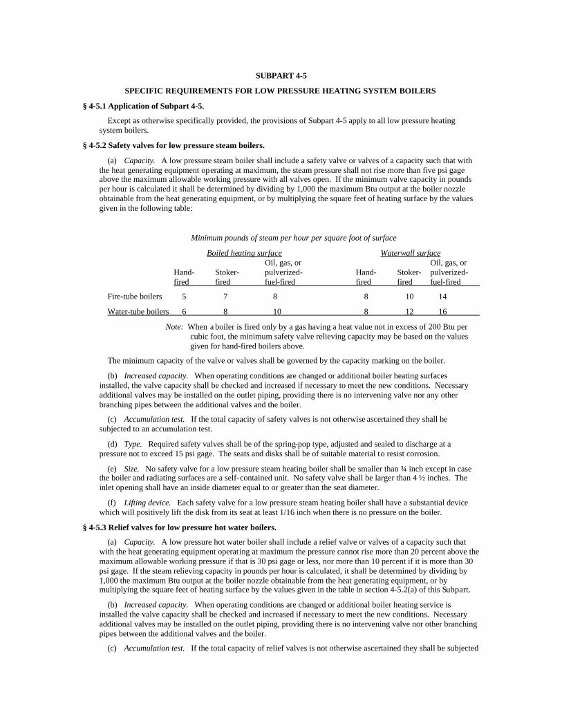
§ 4-5.2 Safety valves for low pressure steam boilers.
(a) Capacity. A low pressure steam boiler shall include a safety valve or valves of a capacity such that with the heat generating equipment operating at maximum, the steam pressure shall not rise more than five psi gage above the maximum allowable working pressure with all valves open. If the minimum valve capacity in pounds per hour is calculated it shall be determined by dividing by 1,000 the maximum Btu output at the boiler nozzle obtainable from the heat generating equipment, or by multiplying the square feet of heating surface by the values given in the following table:
Minimum pounds of steam per hour per square foot of surface
Boiled heating surface Waterwall surface Oil, gas, or Oil, gas, or Hand- Stoker- pulverized- Hand- Stoker- pulverized- fired fired fuel-fired fired fired fuel-fired
Fire-tube boilers 5 7 8 8 10 14
Water-tube boilers 6 8 10 8 12 16
Note: When a boiler is fired only by a gas having a heat value not in excess of 200 Btu per cubic foot, the minimum safety valve relieving capacity may be based on the values given for hand-fired boilers above.
The minimum capacity of the valve or valves shall be governed by the capacity marking on the boiler.
(b) Increased capacity. When operating conditions are changed or additional boiler heating surfaces installed, the valve capacity shall be checked and increased if necessary to meet the new conditions. Necessary additional valves may be installed on the outlet piping, providing there is no intervening valve nor any other branching pipes between the additional valves and the boiler.
(c) Accumulation test. If the total capacity of safety valves is not otherwise ascertained they shall be subjected to an accumulation test.
(d) Type. Required safety valves shall be of the spring-pop type, adjusted and sealed to discharge at a pressure not to exceed 15 psi gage. The seats and disks shall be of suitable material to resist corrosion.
(e) Size. No safety valve for a low pressure steam heating boiler shall be smaller than ¾ inch except in case the boiler and radiating surfaces are a self-contained unit. No safety valve shall be larger than 4 ½ inches. The inlet opening shall have an inside diameter equal to or greater than the seat diameter.
(f) Lifting device. Each safety valve for a low pressure steam heating boiler shall have a substantial device which will positively lift the disk from its seat at least 1/16 inch when there is no pressure on the boiler.
§ 4-5.3 Relief valves for low pressure hot water boilers.
(a) Capacity. A low pressure hot water boiler shall include a relief valve or valves of a capacity such that with the heat generating equipment operating at maximum the pressure cannot rise more than 20 percent above the maximum allowable working pressure if that is 30 psi gage or less, nor more than 10 percent if it is more than 30 psi gage. If the steam relieving capacity in pounds per hour is calculated, it shall be determined by dividing by 1,000 the maximum Btu output at the boiler nozzle obtainable from the heat generating equipment, or by multiplying the square feet of heating surface by the values given in the table in section 4-5.2(a) of this Subpart.
(b) Increased capacity. When operating conditions are changed or additional boiler heating service is installed the valve capacity shall be checked and increased if necessary to meet the new conditions. Necessary additional valves may be installed on the outlet piping, providing there is no intervening valve nor other branching pipes between the additional valves and the boiler.
(c) Accumulation test. If the total capacity of relief valves is not otherwise ascertained they shall be subjected

to an accumulation test.
(d) Type. Required relief valves shall be of the valve. The seats and disks of relief valves shall be of material suitable to resist corrosion. No materials likely to fail due to deterioration or vulcanization when subjected to any temperature, not exceeding 275° F. shall be used for any part.
(e) Setting. One required relief valve shall be set to relieve at a pressure at or below the maximum allowable working pressure of the boiler and so arranged that it cannot be reset to relieve at a pressure higher than the maximum allowable working pressure of the boiler. Any additional valve or valves may be set to relieve at pressures not exceeding by more than 20 percent the lowest pressure to which any other valve is set.
(f) Size. No required relief valve shall be smaller than 3/4 inch nor larger than 4 1/2 inch standard pipe size. The inlet opening shall have an inside diameter equal to or greater than the seat diameter. In no case shall the minimum opening through any part of the valve be less than 1/4 inch diameter or its equivalent area.
(g) Lifting device. Each relief valve shall have a substantial device which will positively lift the disk from its seat at least 1/16 inch when there is no pressure on the boiler.
§ 4-5.4 Installation and replacement of safety and relief valves for low pressure boilers.
(a) Required. Such valves shall be installed or reinstalled and shall be in proper working order before the boiler is placed in service.
(b) Loading. No person shall in any manner load or excess of the maximum allowable stated on the certificate of inspection.
(c) Connection of safety valves. Safety valves shall be connected to boilers with the spindle vertical if possible, either directly to a tapped or flanged opening in the boiler, to a fitting connected to the boiler by a close nipple, to a Y-base, to a valveless steampipe between adjacent boilers, or to a valveless header connecting steam outlets on the same boiler.
(d) Connection of relief valves. Relief valves shall be connected to the top of boilers, with the spindle vertical if possible, either directly to a tapped or flanged opening in the boiler, to a fitting connected to the boiler by a close nipple, to a Y-base, to a valveless waterpipe between adjacent boilers, or to a valveless header connecting water outlets on the same boiler.
(e) Y-base. When a Y-base is used, the inlet area shall be not less than the combined outlet areas.
(f) Multiple valves. When the size of the boiler requires a safety valve or relief valve larger than 4 1/2-inch diameter, two or more valves having the required combined capacity shall be used. When two or more valves are used on a boiler they may be single, directly attached, or mounted on a Y-base.
(g) Shutoffs. No shutoff of any description shall be placed between the safety or relief valve and the boiler, nor on discharge pipes between such valves and the atmosphere.
(h) Internal pipes. Safety and relief valves shall not be connected to an internal pipe in the boiler.
(i) Discharge pipes. When a discharge pipe is used, its area shall be not less than the area of the valve or aggregate area based on the nominal diameters of the valves with which it connects, and the discharge pipe shall be fitted with an open drain to prevent water from lodging in the upper part of the valve or in the pipe. When an elbow is placed on a safety valve or a relief valve discharge pipe, it shall be located close to the valve outlet. The pipe shall be supported so that no undue stress is placed on the valve body.
(j) Scalding. The discharge from safety or relief valves shall be so arranged that there will be no danger of scalding persons or damaging equipment.
§ 4-5.5 Gages.
(a) Steam gage. A low pressure steam boiler shall have a steam gage connected to its steam space or its water column, or to its steam connection, by means of a siphon or equivalent device exterior to the boiler and of sufficient capacity to keep the gage tube filled with water and so arranged that the gage cannot be shut off from the boiler except by a cock with tee or lever handle, placed in the pipe near the gage. The handle of the cock shall be parallel to the pipe in which it is located when the cock is open.
(b) Steam gage dial. (1) The scale on the dial of a steam boiler steam gage shall be evenly graduated in one pound increments from zero to not less than 30 psi gage pressure.
(2) The gage shall be provided with effective stops for the indicating pointer at the zero point and at the maximum pressure point. The travel of the tip of the pointer from zero to 30 psi gage pressure shall be along the scale in an arc of 180 degrees and at least one inch radius.

(3) This requirement does not apply to dials installed before March 31, 1965 which provide equivalent or better legibility.
(c) Pressure or altitude gages. A low pressure hot water boiler shall have a pressure or altitude gage connected to it or to its flow connection in such a manner that it cannot be shut off from the boiler except by a cock with tee or lever handle, placed on the pips near the gage. The handle of the cock shall be parallel to the pipe in which it is located when the cock is open.
(d) Pressure or altitude gage dial. The scale on the dial of the pressure or altitude gage shall be graduated to not less than one and one-half times the maximum allowable working pressure. The gage shall be provided with effective stops for the indicating pointer at the zero point and at the maximum pressure point.
(e) Pressure or altitude gage connections. Pressure or altitude gage connections shall be of nonferrous composition when smaller than one inch pipe size and longer than five feet between the gage and the point of connection to the boiler, and also when smaller than 1/2 inch and shorter than five feet between the gage and the point of connection to the boiler. The size of any nonferrous pipe or tubing used shall be not less then 1/4 inch.
§ 4-5.6 Installation and replacement of steam gages for low pressure boilers.
Each steam boiler shall have a steam gage connected to its steam space or to its water column or to its steam connection. The gage or connection shall contain a siphon or equivalent device which will develop and maintain a water seal that will prevent steam from entering the gage tube. The connection shall be so arranged that the gage cannot be shut off from the boiler except by a cock placed in the pipe at the gage and provided with a tee or lever handle arranged to be parallel to the pipe in which it is located when the cock is open. The connections to the boiler (except the siphon, if used) shall be not less than ¼ inch standard pipe size, but when steel or wrought iron pipe or tubing is used, they shall be not less than 1/2 inch inside diameter. The minimum size of a siphon, if used, shall be ¼ inch inside diameter.
§ 4-5.7 Water gage glasses.
Each steam boiler shall have one or more water gage glasses attached to the water column or boiler by means of valved fittings, with the lower fitting provided with a drain valve of the straightway type with opening not less than ¼ inch diameter. Gage glass replacement shall be possible with the boiler under pressure. Transparent material other than glass may be used for the water gage if suitable for the pressure, temperature and corrosive conditions encountered in service.
§ 4-5.8 Stop valves and check valves.
If a boiler may be closed off from the heat distributing system by closing a steam stop valve, there shall be a check valve in the condensate return line between the boiler and the system; and if any part of a heat distributing system may be closed off from the remainder of the system by closing a steam stop valve, there shall be a check valve in the condensate return line from that part of the system. Such check valve shall be placed to prevent boiler contents from entering the distributing system. In lieu of a check valve in the condensate return line, a proper return loop may be provided.
§ 4-5.9 Feedwater connections.
Feedwater connections shall be independent of any water gage connections. Feedwater connections for cast iron steam boilers, when introduced from a pressure line, shall be made to the condensate return line or the reservoir of the condensate return pump, not directly to the boiler. There shall be a check valve in the feedwater line at the boiler for all boilers.
§ 4-5.10 Condensate level control.
Each condensate return tank, where practicable, shall be provided with an automatic water level control set to maintain the water level within the limits of the gage glass.
§ 4-5.11 Thermometers.
Each hot water boiler shall have a thermometer so located and connected that it shall be easily readable when observing the water pressure or altitude. The thermometer shall be so located that it shall at all times indicate the temperature in degrees Fahrenheit of the water in the boiler at or near the outlet.
§ 4-5.12 Combustion regulators.
Each automatically fired hot water heating boiler shall be provided with a temperature actuated control which win control the rate of combustion to prevent the temperature of the water from rising above 250° F at or near the boiler outlet and each automatically fired steam boiler shall be provided with a pressure-actuated combustion control which shall operate to prevent the steam pressure from rising above 15 psi. Such control for a hot water

boiler shall be incapable of being set so as to permit operation of the heat generating apparatus if the temperature of the water is higher than 250° F.

§ 4-5.13 Bottom blowoff.
Each boiler shall have a blowoff pipe connection fitted with a valve or cock not less than 3/4 inch pipe size connected with the lowest water space practicable.
§ 4-5.14 Water column and water level control pipes.
The minimum size of ferrous or nonferrous pipes connecting a water column to a steam boiler shall be one inch. The steam connection to the water column of a horizontal-return tubular boiler shall be taken from the top of the shell or the upper part of the head; the water connection shall be taken from a point not less than six inches below the center line of the shell. No outlet connections, except for damper regulator, feedwater regulator, steam gages or apparatus which does not permit the escape of any steam or water therefrom except for manually operated blowdowns, shall be attached to a water column or the piping connecting a water column to a boiler. If the water column, gage glass, low water fuel cutoff or other water level control device is connected to the boiler by pipe and fittings, no shut-off valves of any type shall be placed in such pipe; and a cross tee, or equivalent, in which a drain valve and piping may be attached, shall be placed in the water piping connection at every right angle turn to facilitate cleaning.
§ 4-5.15 Low water cutoffs.
(a) Devices required. Each automatically fired steam or vapor system boiler, regardless of date of installation, and each automatically fired hot water boiler installed after January l, 1966, shall be equipped with an automatic low water fuel cutoff, so located as to automatically cut off the fuel supply when the surface of the water falls to the lowest safe water line. If a water feeding device is installed, it shall be so constructed that the water inlet valve cannot feed water into the boiler through the float chamber and it shall be so located as to supply the requisite feedwater. The lowest safe water line shall be not lower than the lowest visible part of the water glass.
(b) Attachment. Such a fuel or feedwater control device may be attached direct to a boiler, or to the tapped openings provided for attaching a water glass direct to a boiler, provided that such connections from the boiler are nonferrous tees or Y's not less than 1/2 inch pipe size between the boiler and the water glass, so that the water glass is attached direct and as close as possible to the boiler. The straightway tapping of the Y or tee shall take the water glass fittings, and the side outlet of the Y or tee shall take the fuel cutoff or the water feeding device. The ends of all nipples shall be reamed to full-size diameter.
(c) Drain pipe. Designs embodying a float and float bowl shall have a vertical straightway valved drain pipe at the lowest point in the water equalizing pipe connections by which the bowl and the equalizing pipe can be flushed and the device tested.
(d) Boilers consisting of continuous piping affording no reservoir or water level practicable for the operation of a low water cutoff may be equipped with a flow valve or other suitable control which has been tested and approved in accordance with a code or standard commonly applied in the industry, e.g., AGA or UL.
(e) Heat generating apparatus shall be regarded as a new installation and subject to all applicable provisions relating to installations made after January 1, 1966 whenever both an existing burner and controls are replaced by a new burner and controls.
§ 4-5.16 Accessibility and visibility.
The water gage on a steam boiler shall be accessible without the use of tools and the water gage and pressure gage on a steam boiler and the thermometer and pressure gage on a water boiler shall be visible.
§ 4-5.17 High limit controls.
(a) Application of this section. This section shall apply only to low pressure automatically fired heating system boilers installed after March 31, 1965. Heat generating apparatus shall be regarded as a new installation and subject to all applicable provisions relating to installations made after March 31, 1965 whenever both an existing burner and controls are replaced by a new burner and controls.
(b) Hot water boilers. In addition to the operating limit control, each hot water boiler shall be provided with a high limit temperature-actuated control which by interruption of an electrical circuit will automatically stop the heat generating apparatus if the temperature of the water at or near the boiler outlet rises to 30 degrees Fahrenheit above the maximum allowable working temperature of the boiler.
(c) Steam boilers. In addition to the operating limit control, each steam boiler shall be provided with a high limit pressure-actuated control which by interruption of an electrical circuit will automatically stop the heat generating apparatus if the steam pressure rises to five pounds psi gage above the maximum allowable working pressure of the boiler.

(d) Adjustment. Such control shall be adjustable and capable of being firmly fixed or sealed in proper adjustment. Fixed or sealed as used herein means that the control device shall be so arranged that it will not change during normal operation of the boiler.
(e) Manual reset. Each such control shall be of the manual reset type, designed to reclose only by manual operation.
(f) Circuits. Each such control shall be so incorporated into the electrical circuit essential to the operation of the heat generating apparatus that its automatic operation shall interrupt an ungrounded conductor and stop the heat generating apparatus regardless of the functioning of any other electrical device.
§ 4-5.18 Modular low pressure systems.
(a) Hot water modular systems comprised of no more than 10 boilers with a combined maximum input of no more than 3,000,000 BTU/hr may be equipped with one low water cutoff and one high limit manual reset temperature control provided that there are no stop valves between each boiler and the supply and return lines.
(b) Steam or vapor modular systems comprised of no more than 10 boilers with a combined maximum input of no more than 3,000 lbs/hr may be equipped with one high limit manual reset pressure control provided that there are no stop valves between each boiler and the supply and return lines.
(c) The modular systems described in subdivisions (a) and (b) of this section shall cover no more than 100 square feet of floor area.
(d) One stop valve must be installed in the common supply and common return lines which shall not isolate the controls from the boilers.
(e) The clearance requirements in sections 4-6.4 and 4-6.5 of this Part between each boiler in a modular system need not be met provided that there are no controls or other equipment located on the sides of each boiler which would require maintenance or inspection.
SUBPART 4-6
INSTALLATIONS, REPAIRS AND REPLACEMENT OF LOW PRESSURE HEATING SYSTEM BOILERS
§ 4-6.1 Responsibility of owner.
When any work is to be done on a boiler or component by way of installation, repair, reassembly or replacement, which if improperly performed may create a defect, the owner shall use due care to have the work done by competent persons.
§ 4-6.2 Responsibility of installers and repairers.
All persons in charge of the work of installing, repairing, reassembling or replacing boilers or components shall use due care to have the work done in a neat, workmanlike and safe manner. Patch and welding repairs shall be performed in accordance with Subpart 14-3 of Industrial Code Rule 14.
§ 4-6.3 Clearance for boilers installed before March 31, 1965.
Where necessary for proper operation, maintenance and inspection, clearance shall be provided from building walls, partitions, ceilings or other structures.
§ 4-6.4 Clearance for boilers installed after March 31, 1965 in a space or room not previously used to house a boiler.
(a) Building wall or partition clearance. The clearance between any component on the side or rear of a boiler and any wall or partition of the building in which it is installed shall be not less than 24 inches where the rated gross capacity is less than 5,000,000 Btu per hour. Where the rated gross capacity exceeds 5,000,000 Btu per hour, the clearance to any unprotected combustible construction shall be not less than 36 inches.
(b) Clearance from other boilers or equipment. The clearance between any component of the boiler and any other boiler or equipment shall be not less than 24 inches.
(c) Front operating clearance. The clearance from the front wall or head or heat generating apparatus of the boiler, whichever is closer to the building wall partition or other equipment, shall be not less than four feet where the rated gross capacity is less than 5,000,000 Btu per hour. Where the rated gross capacity exceeds 5,000,000 Btu per hour, such clearance shall be not less than six feet.
(d) Working platform -- vertical clearance. When working platforms, required for boilers where the distance

from the floor to the top of the boiler or boiler setting exceeds eight feet, are installed on top of a boiler for operating or maintenance purposes, the clearance from the working surface of such platform to the lowest point of any overhead structure shall be not less than seven feet.

§ 4-6.5 Clearance for boilers installed after March 31, 1965 in a space or room which previously housed a boiler.
(a) General clearance. Sufficient clearance shall be provided from building walls, partitions and overhead ceilings or structures to allow for proper operation, maintenance and inspection.
(b) Vertical clearance. Where it is necessary for a person to work on top of the boiler, the clearance between the top of the boiler and the underside of any overhead structure shall be not less than three feet. The clearance from the part of any valve or fitting which moves when the valve or fitting is opened or closed, shall be not less than six inches when such valve or fitting is at maximum open.
§ 4-6.6 Working platforms and ladders -- boilers installed after March 31, 1965.
(a) Working platform requirements. Any working platform required by this section shall be not less than 24 inches wide, constructed of metal with a four-inch metal toeboard, and have railings not less than 42 inches high with a midrail. Such railings shall be constructed of not less than 1 1/4 inch diameter pipe.
(b) Ladders and stairs. Any ladder required by this section shall be of substantial construction of metal, and be at least 18 inches wide between side rails. Any stairs required by this section shall be of metal not less than 24 inches wide, with a metal railing not less than 42 inches high with a midrail. Such railing shall be constructed of not less than 1 1/4 inch diameter pipe.
(c) Access to boiler top. Where the distance from the floor to the top of a boiler or boiler setting exceeds eight feet, a permanent stairway or inclined ladder shall be provided to give safe access to and permit exit from the boiler top. Where more than two boilers are operated in battery, two remote means of exit from the boiler tops shall be provided, one of which may be a vertical ladder.
(d) Access to valves. Where a main stop valve, a safety valve or a relief valve is located on top of a boiler, a permanent working platform shall be installed to provide access unless the top of the boiler setting is flat and provides an unobstructed walkway not less than 24 inches wide to the valve. Where a main stop valve is located remote from the boiler top and more than six feet above the floor or nearest walkway, a permanent working platform shall be installed.
(e) Access to water column. Where the low point of a water column is located 10 feet or more above the floor or nearest walkway, a working platform shall be installed to provide access to the water column. A permanent ladder or stair need not be provided.
(f) Access to drum of water tube boiler. Where the bottom of the drum of a water tube type boiler is located four feet or more above the floor or nearest walkway, a working platform shall be installed at one end to permit safe access to the drum interior for cleanout and inspection. A permanent ladder or stair need not be provided.
(g) Access to cleanout openings. Where the bottom of cleanout openings on the side walls of a boiler setting are located four feet or more above the floor or nearest walkway, a working platform shall be installed to provide access. A permanent ladder or stair need not be provided.
§ 4-6.7 Access for inspection -- water tube type boilers installed after March 31, 1965.
A water tube type boiler shall be installed so that all drum heads will be accessible for external inspection.
§ 4-6.8 Requirement for boiler room exits -- boilers installed after March 31, 1965.
(a) Boilers installed in existing spaces or rooms. If a boiler is installed after March 31, 1965 in a space or room constructed before March 31, 1965, which previously housed a boiler, such space or room shall be provided with at least one exit not less than 30 inches wide. If a door is provided it shall open in the direction of egress.
(b) Boilers installed in new spaces or rooms. If a boiler is installed after March 31, 1965, in a space or room which was not previously used to house a boiler, such space or room which has an area of less than 300 square feet shall be provided with at least one exit not less than 36 inches wide. If a door is provided it shall open in the direction of egress. If such space or room has an area of 300 square feet or more, two remote exits shall be provided. One of these exits shall be at least 36 inches wide and if provided with a door, the door shall open in the direction of egress. The other exit may be a permanent vertical or inclined metal ladder not less than 18 inches wide, affording access to an opening having a least dimension of 36 inches. If such opening is provided with a door, it shall open in the direction of egress.
§ 4-6.9 Requirements for boiler room exits -- boilers installed before March 31, 1965.
A boiler room housing a boiler installed before March 31, 1965 shall be provided with at least one exit not less than 30 inches wide. If a door is provided, it shall open in the direction of egress.

SUBPART 4-7
HEAT GENERATING APPARATUS - GENERAL PROVISIONS
§ 4-7.1 Application of this Subpart.
Except as otherwise specifically provided, the provisions of this Subpart apply to all heat generating apparatus without regard to date of installation.
§ 4-7.2 Installation.
(a) Manufacturer's recommendation. Installation of heat generating apparatus and accessories in accordance with recommendations of the manufacturer shall, if otherwise properly made, be deemed in compliance with this Part (rule).
(b) Accessibility. Installations shall be so made as to provide reasonable accessibility for cleaning heating surfaces, removing burners, replacing motors, controls, air filters, draft regulators and other working parts, and for adjusting, cleaning and lubricating parts requiring such attention.
(c) Observation ports. Properly located observation ports shall be provided to permit an operator to observe burner operation under all conditions.
§ 4-7.3 Air supply for combustion.
Sufficient fresh air shall be provided to the heat generating apparatus to allow complete combustion of fuel at all firing rates. For gas- or oil-fired burners, the boiler room shall have at least one square foot of opening for the entry of fresh air for every 2,000,000 Btu of fuel burned per hour.
§ 4-7.4 Maintenance.
(a) General. All equipment used for generation of heat shall be maintained in good condition.
(b) Safety controls. Safety controls shall be properly adjusted and maintained. Inspection and maintenance routines recommended by the manufacturer shall be deemed sufficient. Proper maintenance shall include periodic replacement of electronic tubes in combustion safeguards.
(c) Guarding. All machinery shall be guarded in conformance with Industrial Code Rule No. 19 (12 NYCRR 19).
§ 4-7.5 Electrical equipment and wiring.
(a) General. The general construction and assembly of electrical equipment and wiring shall be neat and workmanlike. Wiring shall be positively located and adequately supported and shall be adequately protected against injury from the movement of movable parts.
(b) Enclosures. Splicing devices and uninsulated metal parts having a potential in excess of 30 volts shall be installed within enclosures requiring the use of tools for entry. Strain relief shall be provided for conductors leaving an enclosure.
(c) Bushings. Openings in metal walls through which insulated wires not in wireways pass shall be provided with smoothly rounded bushings, or an acceptable metal grommet, or shall have smooth well-rounded surfaces as formed by rolling or extrusion of the metal around the opening to prevent abrasion of the insulation. Bushings shall be phenolic, porcelain, hard fiber or other suitable material having a smoothly rounded surface.
(d) Connectors. Detachable plug connectors shall not be used in circuits when disconnection or connection of the circuit may allow unsafe operation of the appliance.
(e) Service connections. Electrical connections, including those in low voltage non-safety circuits, which need to be broken to service any controls, shall be made in such a manner that they may be connected and reconnected without breaking a soldered connection and without breaking or cutting the wires.
SUBPART 4-8
HEAT GENERATING APPARATUS - SPECIAL PROVISIONS
§ 4-8.1 Application of this Subpart.
The provisions of this Subpart apply only to apparatus installed after March 31, 1965.
§ 4-8.2 Control circuits.

Control circuits shall be two wire, one side grounded, having a nominal voltage of 150 volts or less. The circuit shall be connected to a branch circuit that can be fused at not more than the value appropriate for the rating of the electrical components included in the circuit. Safety controls or protective devices shall interrupt ungrounded conductors. Safety controls shall not depend on electricity to attain the off position.
§ 4-8.3 Special requirements for heat generating apparatus fired with pulverized coal.
(a) Explosion vents. Suitable explosion vents extending to the outside air shall be installed on storage bins, cyclone collectors and piping for central storage systems of pulverized coal.
(b) Ignition of pulverized coal. A large and stable pilot flame to insure proper ignition of the pulverized coal shall be provided. Manual ignition with oil soaked torches is prohibited, If an oil burning pilot is used, it shall burn pressure-atomized number two or other light grade fuel oil having a discharge rate of 20 to 50 gallons per hour. If a gas pilot is used, the burner shall deliver gas at a rate of not less than 1,000 cubic feet per hour.
(c) Starting the boiler. A supply of dry coal shall be provided to start the boiler so that proper ignition will result.
(d) Interlocks. Mechanical or electrical interlocks shall be provided on each of the following devices to insure operation only in the order listed, and automatically to shut down all of the units following it in order of operation should any single unit fail.
(1) induced draft fan to purge furnace and passes;
(2) forced draft fan;
(3) primary oil blower;
(4) coal pulverizer; and
(5) coal feeder.
(e) Flue damper interlock. If natural draft instead of induced draft is used, an interlock shall be provided to insure that the flue damper is wide open in case of the failure of the forced draft fan.
(f) Central storage interlocks. If a central storage system is used, electrical interlocks shall be provided on conveyors, pulverizer motors and blowers, and separate blowers which shall automatically shut down all of the units ahead of any single unit in order to prevent coal from piling up in the system if a single unit should fail.
§ 4-8.4 Gas burners.
(a) Accessibility of controls. All controls shall be accessible for normal servicing and adjustment in position and shall be replaceable during normal servicing.
(b) Openings in panels. Openings in perforated or expanded metal panels, provided over combustion air, circulating air or draft hood relief openings, shall be not less than 1/8 inch diameter. If the openings in such panels are other than circular in shape, they shall permit entrance of a number 20 DMS drill.
(c) Sharp edges. All parts of the burner that may come in contact with the operator's hand or arm during normal adjustment or servicing shall be free from sharp projections or edges and projecting screwheads.
(d) Attaching bolts. When tap bolts are used to attach air shutters, manifold supports or other parts which must be removed for normal servicing or replacement, they shall be made of rust resisting material or, if of steel, shall have a metallic rust resisting coating.
(e) Cleanout plate bolts. Heads and nuts of bolts which must be removed to permit the removal of cleanout plates shall not be placed where they will be in contact with flue gases.
(f) Ventilation. Cabinet compartments housing gas piping and controls shall be adequately ventilated. The top or plane of any concealed combustion air or ventilation openings shall not be less than two inches above the floor level. The bottom of such openings shall not be less than one inch above the floor level unless proper operation can be had with the bottom of the opening blocked to a distance one inch above the floor.
§ 4-8.5 Pilot installation.
(a) Flame visibility. Pilots shall be placed so that their flames may be directly observed with the main burners off and also, unless other means are available for checking their operations, with the main burners on.
(b) Dirt protection. Pilots shall be installed so that the ignition port and operating mechanism will not be obstructed by falling scale and dirt in normal operation.
(c) Fastening and removal. Pilot assemblies and bleed assemblies, when used, shall be made secure against

accidental displacement. Pilot assemblies shall be so installed that they may be removed without the use of special tools, and with reasonable care even when hot, without removing main burners, controls or accessories or breaking or disturbing any gas connections other than that of the pilot supply, bleed supply or manifold unions. Pilots may be removed as a unit.
(d) Supply line connection. When the pilot burner supply line is taken from a horizontal line, the connection shall be made either on the side or top. If taken from a vertical line, the connection shall be above the main burner supply line. Pilot supply lines may be taken from the bottom of a horizontal line if means are provided to prevent condensate from entering the pilot line.
(e) Air supply. When an enclosed type of fire box is used, provisions shall be made to assure an adequate supply of air for combustion of the gas from the pilot.
§ 4-8.6 Gas valves.
(a) Lubricants. Lubricants used on valves shall be resistant to the action of liquefied petroleum gases.
(b) Manual pilot shutoff. Manual valve means for turning on and shutting off the gas supply to the pilot burner shall be provided and shall be so located as to be readily accessible.
(c) Manual emergency shutoff. A manual emergency gas shutoff valve, prominently marked and readily accessible, shall be provided for closing in case of fire.
(d) Distinguishable valves. Separate pilot burner valves shall be easily distinguishable from main burner valves.
§ 4-8.7 Gas supply lines.
(a) Bends. Bent supply piping shall have the bends smoothly made without any appreciable reduction in cross-sectional area and shall have no imperfection occasioned by the bending process.
(b) Supports. Gas supply piping, tubing and fittings shall be rigidly supported with pipe hooks, metal pipe straps, bands or hangers suitable for the size of the piping or tubing. Gas piping shall not be supported by other piping.
(c) Rigid assembly. Gas supply piping to which connections are made for burners, pilots, lighters or other branch supply lines shall be so assembled and rigidly supported as to prevent turning or displacement in making connections to the building piping or in the ordinary handling of the unit.
(d) Joint compounds. Compounds used on threaded joints of gas piping shall be resistant to the action of liquefied petroleum gases.
(e) Location of the connections. Connections for pilot gas supply lines shall be so located that pilot lines of semi-rigid tubing and pilot valves will not be unnecessarily exposed to damage hazards.
(f) Iron pipe manifolds. When iron pipe is used for pilot burner manifolds, its nominal size shall be not less than one quarter inch, and when used for individual pilot lines its nominal size shall be not less than one-eighth inch.
(g) Semi-rigid tubing. When semi-rigid tubing is employed as gas conduit, it shall be not less than nominal one quarter inch size.
(h) Aluminum tubing. Aluminum semi-rigid tubing shall not be exposed to condensate or to temperatures in excess of 700° F. Aluminum semi-rigid tubing shall not be used to pass through insulating material of other than neutral reaction unless the tubing is adequately protected from the insulation.
(i) Union types. Unions in gas lines for use with liquefied petroleum gases or LP gas-air mixtures shall be either of the ground joint type or a flanged joint having packing resistant to the action of such gases.
(j) Test gage connection. A one-eighth inch I.P.S. plugged tapping accessible for test gage connection shall be furnished downstream from the last main line gas control for measuring gas pressure at the burner. The plug used shall not be of the slotted head type.
§ 4-8.8 Draft hoods.
(a) Support. Provisions shall be made to assure a firm support of flue piping either to the draft hood or to the flue outlet if a built-in draft hood is provided.
(b) Flue damper. Thermally activated flue dampers and manually operated flue dampers shall not be used. Electrically operated flue dampers manufactured and identified in accordance with AGA or UL requirements shall constitute standard components.


SUBPART 4-9
FLAME SAFEGUARD CONTROLS FOR GAS -FIRED BOILERS
§ 4-9.1 Application of this Subpart.
Except as otherwise specifically provided, the provisions of this Subpart apply to all gas-fired boilers without regard to date of installation.
§ 4-9.2 Devices required.
All gas-fired boilers shall be equipped with adequate flame safeguard devices.
§ 4-9.3 Pilot or torch to be proven.
On manually lighted or automatically ignited gas-fired boilers, the pilot or torch shall be proven at a location where it will reliably ignite the main burner before permitting the main burner gas valve to open either automatically or manually by completing an electrical circuit.
§ 4-9.4 Trial-for-ignition period.
(a) Equipment. Timed trial-for-ignition equipment shall be provided for both the pilot and the main burner.
(b) lnput rating under 400,000 BTU/hr per combustion chamber. For burners with an input rating of less than 400,000 Btu per hour, the trial-for-ignition period for the pilot on automatically fired boilers shall not exceed 90 seconds. The main burner trial-for-ignition period shall not exceed 90 seconds.
(c) Input rating to 5,000,000 BTU/hr per combustion chamber. For burners with an input rating of 400,000 Btu per hour or more, but less than 5,000,000 Btu per hour, the trial-for-ignition period for the pilot for automatically fired boilers shall not exceed 15 seconds. The main burner trial-for-ignition period shall not exceed 15 seconds.
(d) Input rating over 5,000,000 BTU/hr per combustion chamber. For burners with an input rating of 5,000,000 Btu per hour and over, the trial-for-ignition period for the pilot shall not exceed 15 seconds. The main burner trial-for-ignition period shall not exceed 15 seconds. On power or inshot type burners of this size, the pilot shall automatically shut off not more than 15 seconds after the main fuel valve is opened. On atmospheric type burners of this size, a constant burning type pilot is acceptable, providing the pilot is proven before the main gas valve is opened.
§ 4-9.5 Burner flame failure controls.
(a) Input rating under 400,000 Btu. For burners with an input rating less than 400,000 Btu per hour, the main gas valve shall close automatically within 90 seconds after flame failure.
(b) Input rating of 400,000 Btu plus. For burners with an input rating of 400,000 Btu per hour or more, the electrical circuit to the main fuel valve shall be automatically de-energized within four seconds after flame failure and the de-energized valve shall automatically close within the next five seconds.
SUBPART 4-10
GENERAL REQUIREMENTS FOR OIL BURNERS
§ 4-10.1 Application of this Subpart.
The provisions of this Subpart apply to all oil burners, without regard to date of installation.
§ 4-10.2 Controls.
All controls shall be accessible for normal servicing and adjustment in position and shall be replaceable during normal servicing.
§ 4-10.3 Safety controls -- abnormal oil discharge.
Burners shall be equipped with automatic primary safety controls to prevent abnormal discharge of oil at the burner in case of ignition failure or flame failure.
§ 4-10.4 Sharp edges.
Parts of the burner that may normally come in contact with the operator's hand or arm during normal usage shall be free from sharp edges or projections and projecting screwheads or ends.

§ 4-10.5 Locking adjustable parts.
An adjustable or moving part shall be provided with a suitable locking device to prevent accidental shifting.
§ 4-10.6 Strainers.
A small orifice or other opening in an oil supply system likely to become clogged shall he protected by a suitable strainer. A strainer employing an element other than a screen shall have a rated capacity not less than the maximum firing rate of the burner to which it is applied.
§ 4-10.7 Fittings and piping.
Tubing shall be arranged to avoid being physically damaged. A coupling or union which is disconnected for service shall be located so that any oil dripping from the connection will not drip or run onto electrical parts.
§ 4-10.8 Valves.
A petcock or valve which when opened will permit the discharge of fuel oil into the boiler room shall not be used.
§ 4-10.9 Breakable gages.
A glass gage or sight feed, the breakage of which will allow the discharge of fuel oil from the fuel supply system, shall not be used.
SUBPART 4-11
FLAME SAFEGUARD CONTROL REQUIREMENTS FOR ALL OIL BURNERS INSTALLED BEFORE MARCH 31, 1965
§ 4-11.1 Application of this Subpart.
The provisions of this Subpart apply only to oil burners installed before March 31, 1965.
§ 4-11.2 Manual or automatic -- maximum firing rate up to seven gallons per hour.
On all manual or automatic oil-fired burners having a firing rate up to seven gallons per hour, the main flame trial-for-ignition period shall not exceed 90 seconds. Upon flame failure, the main oil valve shall close automatically within 90 seconds.
§ 4-11.3 Manual -- maximum firing rate over seven gallons per hour.
After the burner is manually lit the main flame shall be continually supervised while the burner is firing. The electrical circuit to the main fuel valve shall be automatically de-energized within four seconds after flame failure and the de-energized valve shall automatically close within the next five seconds.
§ 4-11.4 Automatic -- maximum firing rate over seven to 16 gallons per hour.
The main flame trial-for-ignition period shall not exceed 30 seconds and the main flame shall be continually supervised while the burner is firing. Upon flame failure, the main oil valve shall close automatically within 30 seconds if the burner does not relight within this time.
§ 4-11.5 Automatic -- maximum firing rate over 16 to 33 gallons per hour.
The main flame trial-for-ignition period shall not exceed 15 seconds and the main flame shall be continually supervised while the burner is firing. Upon flame failure, the main oil valve shall close automatically within 15 seconds if the burner does not relight within this time.
§ 4-11.6 Automatic -- maximum firing rate over 33 gallons per hour.
The main flame trial-for-ignition period shall not exceed 30 seconds when the burner has a low firing rate start under 16 gallons per hour and shall not exceed 15 seconds when the burner does not have such a low firing rate start. The main flame shall be supervised continually while the burner is firing. The electrical circuit to the main fuel valve shall be automatically de-energized within four seconds after flame failure and the de-energized valve shall automatically close within the next five seconds. The burner may make one attempt to relight automatically during this flame failure reaction time before the valve closes.
§ 4-11.7 Automatic -- proved pilot.

If an automatic type oil-fired boiler is equipped with a proved pilot, regardless of the firing rate, such pilot shall be proved within 15 seconds. The burner shall be so designed and installed that the main oil valve shall open only after the pilot is proved and either such pilot shall automatically shut off within 60 seconds after the main oil valve opens or the pilot sensing device shall be automatically de-energized. On any burner equipped with a proved pilot, regardless of firing rate, the main flame trial-for-ignition period shall not exceed 60 seconds and the main flame shall be continually supervised while the burner is firing. The electrical circuit to the main fuel valve shall be automatically de-energized within four seconds after flame failure and the de-energized valve shall close automatically within the next five seconds. The burner may make one attempt to relight automatically during this flame failure reaction time before the valve closes.
SUBPART 4-12
FLAME SAFEGUARD CONTROL REQUIREMENTS FOR OIL BURNERS INSTALLED AFTER MARCH 31, 1965.
§ 4-12.1 Application of this Subpart.
The provisions of this Subpart apply only to oil burners installed after March 31, 1965.
§ 4-12.2 Special definition of maximum firing rate .
For a burner which is equipped to start on low fire only and whose firing rate cannot properly be increased beyond the low firing rate until ignition of the low fire is proven, the term maximum firing rate used in this Subpart means the firing rate to the largest fire that can be initially ignited.
§ 4-12.3 Manual or automatic -- maximum firing rate three gallons per hour or less.
On all manual or automatic oil-fired boilers having a firing rate of three gallons per hour or less, the main flame trial-for-ignition period shall not exceed 90 seconds. Upon flame failure, the main oil valve shall close automatically within 90 seconds.
§ 4-12.4 Manual -- maximum firing rate over three gallons per hour.
After the burner is manually lit, the main flame shall be continually supervised while the burner is firing. The electrical circuit to the main fuel valve shall be automatically de-energized within four seconds after flame failure and the de-energized valve shall automatically close within the next five seconds.
§ 4-12.5 Automatic -- maximum firing rate over three to seven gallons per hour.
The main flame trial-for-ignition period shall not exceed 30 seconds and the main flame shall be continually supervised while the burner is firing. The electrical circuit to the main fuel valve shall be automatically de-energized within four seconds after flame failure and the de-energized valve shall automatically close within the next five seconds. As an alternative, if intermittent ignition is employed or the ignition system is re-energized in not more than 0.8 second after flame failure, the main oil valve shall close automatically within 30 seconds after flame failure. The burner may make one attempt to relight automatically during this 30-second flame failure reaction time before the valve closes.
§ 4-12.6 Automatic -- maximum firing rate over seven to 20 gallons per hour.
The main flame trial-for-ignition period shall not exceed 15 seconds and the main flame shall be continually supervised while the burner is firing. The electrical circuit to the main fuel valve shall be automatically de-energized within four seconds after flame failure and the de-energized valve shall automatically close within the next five seconds. As an alternative, if intermittent ignition is employed or the ignition system is re-energized in not more than 0.8 second after flame failure, the main oil valve shall close automatically within 15 seconds. The burner may make one attempt to relight automatically during this 15-second flame failure reaction time before the valve closes.
§ 4-12.7 Automatic -- maximum firing rate over 20 gallons per hour.
The burner shall be equipped with a proved pilot and the pilot trial-for-ignition period shall not exceed 15 seconds. The burner shall be so designed and installed that the main oil valve shall open only after the pilot is proven and either such pilot shall automatically shut off within 60 seconds after the main oil valve opens or the pilot sensing device shall be automatically de-energized. The main flame trial-for-ignition period shall not exceed 60 seconds and the main flame shall be continually supervised while the burner is firing. The electrical circuit to the main fuel valve shall be automatically de-energized within four seconds after flame failure and the de-energized valve shall close automatically within the next five seconds.
§ 4-12.8 Automatic -- proved pilot.

If an automatic type oil-fired boiler is equipped with a proved pilot, regardless of the firing rate such pilot shall be proved within 15 seconds. The burner shall be so designed and installed that the main oil valve shall open only after the pilot is proved and either such pilot shall automatically shut off within 60 seconds after the main oil valve opens or the pilot sensing device shall be automatically de-energized. On any burner equipped with a proved pilot, regardless of firing rate the main flame trial-for-ignition shall not exceed 60 seconds and the main flame shall be continually supervised while the burner is firing. The electrical circuit to the main fuel valve shall be automatically de-energized within four seconds after flame failure and the de-energized valve shall close automatically within the next five seconds.
SUBPART 4-13
SPECIAL REQUIREMENTS FOR LOW PRESSURE STEEL PLATE BOILERS
§ 4-13.1 Application of this Subpart.
The provisions of this Subpart apply only to low pressure steel plate boilers installed after March 31, 1965.
§ 4-13.2 Boiler openings.
(a) Openings required. Boiler openings must meet the requirements of section IV of the ASME Code.
(b) Threaded openings. All threaded openings in a boiler shall be tapped into material having a minimum thickness as specified for the various standard pipe sizes in the following table:
MINIMUM THICKNESS OF MATERIAL FOR TAPPINGS Minimum thickness of
material or length of Pipe size thread required (inches) (inches)
1 and under ¼
1¼ to 2, inclusive 5/16
2 1/2 7/16
3 to 3 1/2, inclusive 5/8
4 to 5, inclusive 7/8
6 to 8, inclusive 1
9 to 12, inclusive 1 ¼
§ 4-13.3 Supports.
(a) Horizontal-return boiler over 72 inches in diameter. A horizontal-return tubular boiler over 72 inches in diameter shall be supported from steel hangers by the outside suspension type of setting, independent of the boiler sidewalls. The hangers shall be so designed that the load is properly distributed between the rivets attaching them to the shell and so that no more than two of these rivets come in the same longitudinal line on each hanger. The distance girthwise of the boiler from tile centers of the bottom rivets to the centers of the top rivets attaching the hangers shall be not less than 12 inches. The other rivets used shall be spaced evenly between these points. If more than four hangers are used they shall be set in four pairs.
(b) Horizontal-return boilers 54 inches to 72 inches in diameter. A horizontal-return tubular boiler over 54 inches and up to and including 72 inches in diameter shall be supported by the outside-suspension type of setting or at four points by not less than eight steel or cast-iron brackets set in pairs.
(c) Horizontal-return boilers 54 inches in diameter or less. A horizontal-return tubular boiler up to and including 54 inches in diameter shall be supported by the outside-suspension type of setting, or by not less than two steel or cast-iron brackets on each side.
(d) Lugs and hangers. Lugs and hangers, when used to support a boiler of any type, shall be properly fitted to the surfaces to which they are attached. Where it is impractical to attach them with rivets, studs with not less than 10 threads per inch may be used. If lugs, hangers or brackets are attached by fusion welding, they shall be attached by fillet welds along the entire periphery or contact edges, and the throat dimension of the attachment welds shall be at least 0.7 times the shell thickness.
§ 4-13.4 Setting and installation.

(a) Wet-bottom boilers. Boilers of the wet-bottom type having an external width of over 36 inches shall have not less than 12 inches between the bottom of the boiler and floor line, with access for inspection. When the width is 36 inches or less, the distance between the bottom of the boiler and the floor line shall be not less than six inches, and when any part of the wet bottom is not farther from an outer edge than 12 inches it shall be not less than four inches. If handholes are located in the bottom area of the boiler, the bottom clearance for the boiler shall be not less than 12 inches regardless of width.
(b) Access doors. The minimum size of access doors used in a boiler setting shall be 12 inches by 16 inches, or equivalent area of which the least dimension is 11 inches.
(c) Expansion and contraction. Provision shall be made for the expansion and contraction of steam mains connected to boilers by providing substantial anchorage at suitable points, so that there shall be no undue strain transmitted to the boiler.
(d) Feedwater. Feedwater or makeup water shall not be discharged directly into any part of a boiler exposed to the direct radiant heat from the fire. Feedwater shall not be introduced through the openings or connections used for the relief valve, the water column, or the water gage glass.
(e) Heaters. A heater for oil or other liquid harmful to boiler operations shall not be installed directly in the steam or water space within a boiler. Where an external-type heater for such service is used, means shall be provided to prevent the introduction into the boiler of oil or other liquid harmful to boiler operation.
(f) Fluid-relief columns. All hot water heating systems shall be so installed that there will be no opportunity for the fluid-relief column to freeze or to be accidentally shut off.
(g) Expansion tanks. If the system is equipped with an open expansion tank, an indoor overflow from the upper portion of the expansion tank shall be provided in addition to an open vent, the indoor flow to be carried within the building to a suitable plumbing fixture or to the basement. If the system is of the closed type, an airtight tank or other suitable air cushion shall be installed that will be consistent with the volume and capacity of the system. Provision shall be made for draining the tank without emptying the system.
(h) Return pipe stop valves. When a stop valve is used in the supply pipe connection of a single boiler, there shall be one used in the return pipe connection unless a proper return loop is provided.
(i) Stop valve requirements. A stop valve shall be used in each supply and return pipe connection of two or more boilers connected to a common system. Provision shall be made for cleaning the interior of the return piping at or close to the boiler. When stop valves over two inches in size are used, they shall be of the outside-screw-and-yoke rising-spindle type or of such type as to indicate at a distance by the position of the spindle or other operating mechanism whether it is closed or open, and the wheel may be carried either on the yoke or attached to the spindle. If the valve is of the plug cock type, it must be fitted with a slow-opening mechanism and an indicating device, and the plug must be held in place by a guard or gland.
(j) Stop valve identification. When stop valves are used, they shall be properly designated substantially as indicated by the following tags of metal or other durable material fastened to them:
Supply Valve -- Number ( ) Return Valve -- Number ( )
Do Not Close Without Also Do Not Close Without Also
Closing Return Valve -- Closing Supply Valve -- Number ( ) Number ( )
(k) Connections for safety valves. The area of the opening shall be at least equal to the aggregate area based on the nominal diameters of all of the safety valves with which it connects. A screwed connection may be used for attaching a safety valve.
SUBPART 4-14
SPECIAL REQUIREMENTS FOR CAST-IRON BOILERS
§ 4-14.1 Application of this Subpart.
The provisions of this Subpart apply only to low pressure cast-iron heating system boilers installed after March 31, 1965.
§ 4-14.2 Limited use.
No cast-iron boiler shall be operated as other than a low pressure boiler.

§ 4-14.3 Boiler openings.
(a) Washout openings. All cast-iron steam and hot water boilers shall be provided with suitable washout openings to permit the removal of any sediment that may accumulate therein. Washout openings may be used for return pipe connections and the washout plug placed in a tee so that the plug is directly opposite and as close as possible to the opening in the boiler.

(b) Threaded openings. Pipe connections, if threaded, shall be tapped into material having a minimum thickness as specified in the following table:
MINIMUM THICKNESS OF MATERIAL FOR THREADED CONNECTIONS TO BOILERS Minimum thickness material required Size of pipe connection (inches) (inches)
3/4 and under 5/16
1 to 2 1/2, inclusive 7/16
3 to 3 1/2, inclusive 5/8
4 to 5, inclusive 7/8
6 to 8, inclusive 1
9 to 12, inclusive 1 ¼
§ 4-14.4 Installation requirements.
(a) Expansion and contraction. Provision shall be made for the expansion and contraction of steam mains connected to boilers by providing substantial anchorage at suitable points, so that there shall be no undue strain transmitted to the boiler.
(b) Feedwater. When feedwater or makeup water is introduced from a pressure line, it shall be connected to the piping system and not directly to the boiler. Feedwater shall not be introduced through the opening or connections used for the relief valve, the water column, or the water gage glass.
(c) Fluid-relief columns. All hot water heating systems shall be so installed that there will be no opportunity for the fluid-relief column to freeze or to be accidentally shut off.
(d) Expansion tanks. If a hot water heating system is equipped with an open expansion tank, an indoor overflow from the upper portion of the expansion tank must be provided in addition to an open vent, the indoor overflow to be carried within the building to a suitable plumbing fixture or to the basement. If the system is of the closed type, an airtight tank or other suitable air cushion must be installed that will be consistent with the volume and capacity of the system. Provision must be made for draining the tank without emptying the system.
(e) Return pipe stop valves. Where a stop valve is used in the supply pipe connection of a single boiler, there shall be one used in the return pipe connection unless a proper return loop is provided.
(f) Stop valve requirements. A stop valve shall be used in each supply and return pipe connection of two or more boilers connected to a common system. Provision shall be made for cleaning the interior of the return piping at or close to the boiler. When stop valves over two inches in size are used, they shall be the outside-screw-and-yoke rising-spindle type, or of such type as to indicate at a distance by the position of the spindle or other operating mechanism whether it is closed or open, and the wheel may be carried either on the yoke or attached to the spindle. If the valve is of the plug cock type, it must be fitted with a slow-opening mechanism and an indicating device, and the plug must be held in place by a guard or gland. When stop valves are used, they shall be properly designated substantially as indicated by the following tags of metal or other durable material fastened to them:
Supply Valve -- Number ( ) Return Valve -- Number ( )
Do Not Close Without Also Do Not Close Without Also Closing Return Valve -- Closing Supply Valve -- Number ( ) Number ( )
(g) Connections for safety valves. The area of the openings shall be at least equal to the aggregate area based on the nominal diameters of all the safety valves with which it connects. A screwed connection may be used for attaching a safety valve.

SUBPART 4-15
HYDROSTATIC TESTS
§ 4-15.1 New boilers.
Hydrostatic tests for new boilers shall be performed in accordance with the ASME Code.
§ 4-15.2 Used boilers.
Hydrostatic tests for used boilers shall be done as required by the inspector.