Embed Size (px)
Citation preview

P4-1
Part 4 of 6: SPRINGS AND GEARS
Table of Contents
1 Springs ............................................................................................................ 2
1.1 What is a spring? ..................................................................................... 2 1.2 Uses of springs ......................................................................................... 2 1.3 Characteristics of spring materials .......................................................... 3 1.4 Metal springs ........................................................................................... 4
1.4.1 Energy storage modes in metallic springs ........................................ 4 1.4.2 Examples of springs of various configurations ................................ 7 1.4.3 Examples of the application of springs ........................................... 12 1.4.4 Diaphragm springs and Belleville washers ..................................... 14
1.5 Non-metallic springs .............................................................................. 17 1.5.1 Rubber springs ................................................................................. 17 1.5.2 Air springs ........................................................................................ 19
2 Gears .............................................................................................................. 21 2.1 Pitch diameter ......................................................................................... 21 2.2 Tooth form ............................................................................................. 23 2.3 Gear configurations ............................................................................... 24 2.4 Uses of gears .......................................................................................... 26 2.5 Advantages of gears ............................................................................... 27 2.6 Disadvantages of gears .......................................................................... 27 2.7 Gear trains ............................................................................................. 28 2.8 Commercial gearboxes .......................................................................... 30

P4-2
1 Springs
1.1 What is a spring?
The spring configurations discussed in this project are readily identifiable, separate machine elements of various configurations, having the primary function of being a spring. This means undergoing significant deflection under load, thereby absorbing energy in the form of strain energy. However, it is important to note that ALL machine members deflect under load (although their deflection is usually small) and thereby absorb and store energy in the form of strain energy. In doing so, they therefore act as springs. Nevertheless, we usually reserve the word SPRING to mean a machine element whose primary function is to undergo relatively large deflection of some kind, thereby storing a relatively large amount of strain energy.
1.2 Uses of springs
Springs are an important and frequently used component in mechanical engineering. Whilst most people are able to recognise a few standard spring configurations, the range of springs is actually much broader: they have many different forms and perform a number of quite separate and distinct functions, with one spring often combining several functions.
Some of the functions of springs, broadly defined, are shown in the table below.
Purpose Example
Carry load Suspension springs of a car.
Apply force Throttle return spring for car engine. Spring-set brake. Counterbalance springs for desk lamp. Spring-loaded safety valve.
Measure force Spring balance.
Control movement Valve spring of a car engine. Belleville washers to provide axial pre-load for bearings. Throttle return spring for car engine.
Reduce impact force Rubber tyres. Car and truck suspension springs. Rubber buffers.

P4-3
Isolate vibration Motor car seats. Motor car suspension. Motor car engine mountings.
Take up slack Belleville washers located behind a bearing (also provides pre-load).
Store energy Bungy jump. Spear-gun rubber. Hydraulic accumulator. Air compressor tank. English long bow.
1.3 Characteristics of spring materials
Figure 4-1 Force-deflection curve for spring material with LOW
HYSTERESIS
Figure 4-2 Force-deflection curve for spring material with HIGH HYSTERESIS
Perhaps the most important requirement for a spring material is the ability to store a large amount of strain energy. This is usually best achieved by choosing materials with a high ELASTIC MODULUS, E, together with an ability to carry a high stress within the material’s elastic range, that is, without permanent deflection. Depending on the application, it may also be important to be able either to recover the stored energy without excessive losses, or to absorb (or dissipate) as much of the stored energy as possible in order to prevent rebound.
A measure of the energy-absorbing characteristics of a spring is given by a force-deflection diagram showing the loading and unloading curves. For most spring configurations using metal springs, as in Fig 4-1, the loading and unloading lines are straight, indicating a linear characteristic (i.e. constant stiffness) and the

P4-4
loading and unloading lines are effectively parallel and very close together. It follows that virtually all the energy stored during loading is recovered during unloading. Such materials are referred to as having LOW HYSTERESIS.
In other applications, such as vibration absorption, it is of advantage to have the absorbed energy dissipated within the spring. Fig. 4-2 shows the characteristics of a material such as rubber or polymer. The loading line is usually curved and of increasing slope, indicating increasing stiffness. Unloading begins with a large drop in force with no change in deflection, then a curved line which may reach zero force before deflection reaches zero – in other words, the material may be permanently stretched by a single application of load. This effect can be observed by stretching an ordinary rubber band. Materials having such characteristics are referred to as having HIGH HYSTERESIS and the area enclosed by the loading-unloading cycle is a measure of the energy lost during one cycle of loading, and hence is a measure of hysteresis.
1.4 Metal springs
Metals generally have a hysteresis curve like that shown in Fig. 4-1. Some commonly used metallic spring materials are:
Carbon steel, heat treated and tempered Alloy steel, heat treated and tempered Brass, work hardened Phosphor bronze, work hardened Stainless steel Beryllium copper
1.4.1 Energy storage modes in metallic springs
The energy storage mode is important for a number of reasons and will vary to suit the application. Some possible modes, with appropriate comments, are described below.

P4-5
Figure 4-3 Figure 4-4
Figures 4-3 and 4-4 Spring deflections for different energy storage modes.
Fig. 4-3 shows a member in axial tension. In this case, the deflections are
always very small and the applied force is very high. Such a member forms a very stiff spring and is therefore seldom used as a spring. Note however that a bolt acts in this way after it has been tightened and its springiness (elastic deflection) is important in keeping a bolted joint from moving. Also, a wire rope used to lower a lift cage down a deep mineshaft will have significant elongation under load and a sudden stop of the raising or lowering mechanism will cause the wire to stretch and “bounce” the load-carrying cage with potentially dangerous results.
Similar considerations regarding small axial deflection apply if the member shown in Fig. 4-3 is loaded in compression. However, another difficulty then occurs - a long slender member under compressive loading may BUCKLE and collapse completely.
Fig. 4-4 also shows examples of metal springs in bending, as a cantilever (top – often used in electrical relays) and as a beam (e.g. a leaf spring used on the rear suspension of some older model cars). By changing the size of the beam cross-section and its length, large variations in spring stiffness are possible. Note that when a simply supported beam is bent, its apparent length changes. In Fig 4-4, this is catered for by the SHACKLE LINK.

P4-6
Figure 4-5 Figure 4-6
Figures 4-5 and 4-6 Spring deflections for different energy storage modes (continued).
Fig. 4-5 shows diagramatically a spring which stores strain energy purely in
torsion, i.e. by twisting the round TORSION BAR when a force is applied to the lever arm attached to the end of the bar. It is normally the case that both ends of the bar are supported, as in Fig 4-5, so the bar is subjected to almost pure torsion, with negligible bending.
The loading condition for axial forces applied to HELICAL COIL SPRINGS (Fig. 4-6) is more complex, being a combination of BENDING PLUS TORSION. Helical coil springs may be used with either a tensile force (top right) or compressive force (lower right). Where helical coil springs are used as torsion springs, the stresses on the spring are mainly bending. A similar bending stress condition exists in spiral torsion springs, such as the clock spring seen in Fig 4-10 below.

P4-7
1.4.2 Examples of springs of various configurations
1.4.2.1 Compression springs
Figure 4-7 Top: Terminology for COMPRESSION springs. The spring absorbs energy by becoming shorter (i.e. compressing) due to the application of compressive loads. The spring must never be compressed to its SOLID LENGTH since its stiffness at that point suddenly becomes ‘infinite’ (actually, not infinite but very high) so the applied forces may suddenly increase and associated components may break. Lower: Illustrating left-hand wound (left-hand helix) and right-hand wound springs. The end coils are often modified so that the ends of the spring are able to fit between parallel surfaces of the machine. As shown in the figure, the ends may be ‘set’ (i.e. bent or ‘squared’), or the ends may be ground flat or, for more critical designs, squared then ground flat. Shigley & Mischke Mechanical Engineering Design 6E McGraw Hill ISBN 0-07-365939-8 page 593.

P4-8
Figure 4-8 Variations of HELICAL COMPRESSION SPRINGS. In the conical and shaped springs, the SPRING RATE, i.e. the deflection caused by unit increase in load, varies as a function of deflection. The spring becomes stiffer the further it is deflected. Left: http://www.masterspring.com/products/compression_springs/default.html Right: http://tricorindustries.com/Pictures_Springs.htm

P4-9
1.4.2.2 Tension springs
Figure 4-9 Typical nomenclature and end configurations for TENSION SPRINGS or EXTENSION SPRINGS. The end coils are usually bent to form hooks or eyes of various shapes so that the spring can easily be attached to machine components. Reproduced from Shigley J.E. and Mischke, C R, Mechanical Engineering Design, 6E, 2003, McGraw Hill page 591, courtesy of Associated Spring Corporation.
Tension or extension springs absorb energy by becoming longer (i.e. extending) due to the application of tensile loads. Care must be taken to ensure that tension springs are not overloaded, resulting in permanent extension or stretching.
Attachment of extension springs can be a problem and the lower pictures in Fig 4-9 show some common end configurations. Tension springs almost always fail where sharp bends associated with the attachment loops or hooks cause stresses to be increased. Stresses in the end fittings can be lowered by gradually reducing the diameter of the end turns, as shown in the picture at lower right.
P4-10
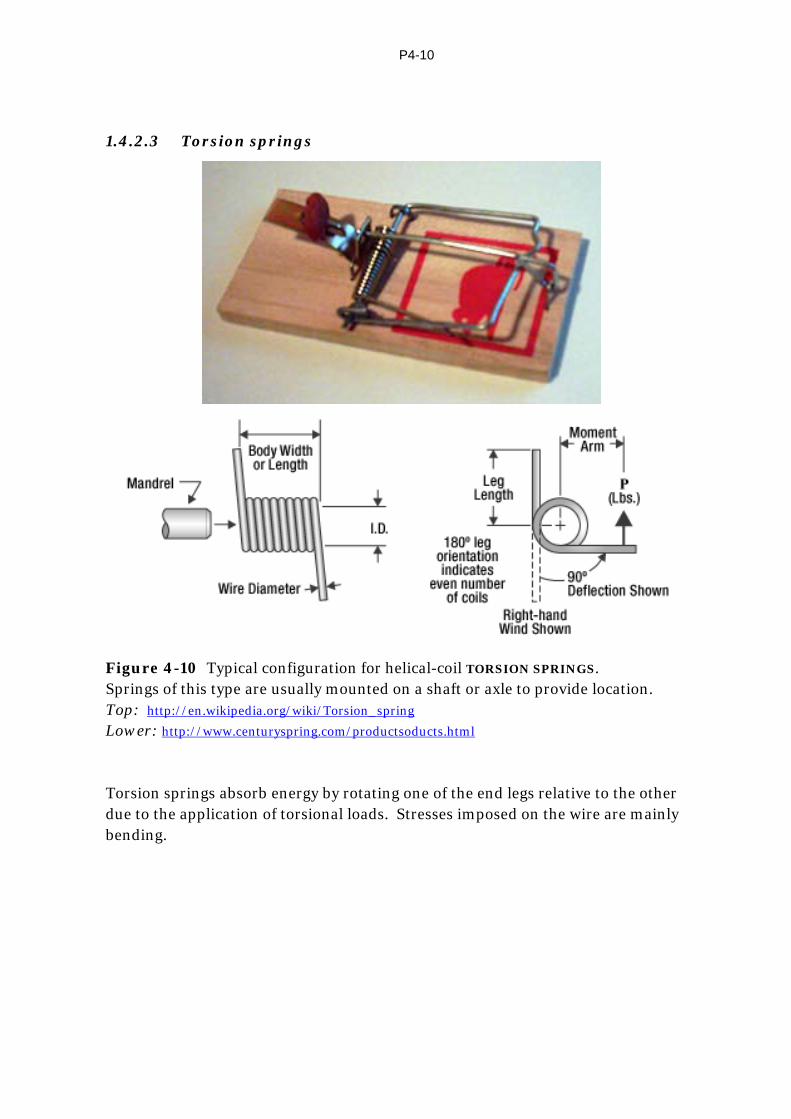
1.4.2.3 Torsion springs
Figure 4-10 Typical configuration for helical-coil TORSION SPRINGS. Springs of this type are usually mounted on a shaft or axle to provide location. Top: http://en.wikipedia.org/wiki/Torsion_spring Lower: http://www.centuryspring.com/productsoducts.html Torsion springs absorb energy by rotating one of the end legs relative to the other due to the application of torsional loads. Stresses imposed on the wire are mainly bending.

P4-11
http://www.boynessprings.com.au/compression_springs.html
http://www.boynessprings.com.au/tension_springs.html
http://www.boynessprings.com.au/torsion_springs.html
Figure 4-11 A few additional examples of available spring types.
P4-12
1.4.3 Examples of the application of springs
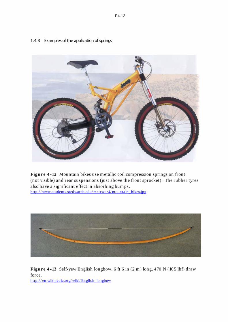
Figure 4-12 Mountain bikes use metallic coil compression springs on front (not visible) and rear suspensions (just above the front sprocket). The rubber tyres also have a significant effect in absorbing bumps. http://www.students.stedwards.edu/mstewar4/mountain_bikes.jpg
Figure 4-13 Self-yew English longbow, 6 ft 6 in (2 m) long, 470 N (105 lbf) draw force. http://en.wikipedia.org/wiki/English_longbow

P4-13
Figure 4-14 Left: A type of compression spring called a VOLUTE SPRING (compare with Fig 4-11) which allows the coils to slide inside each other, greatly reducing spring length when compressed. Right: A volute spring (this one is actually a barrel shape) used to open the handles of a pair of secateurs. http://en.wikipedia.org/wiki/Volute_spring
Figure 4-15 A multi-leaf spring used in the rear suspension of a military vehicle. The spring consists of about 10 leaves of different length to provide the desired characteristics of stiffness and load capacity. Note the use of the swinging shackle link at the rear to allow for the change in length as the spring leaves become less curved under load. http://en.wikipedia.org/wiki/Leaf_spring
Figure 4-16 Drawing of a military cross-bow, invented and drawn by Leonardo de Vinci (1452–1519) , using laminated timber as the spring element. The design includes a winch for drawing back the bowstring and wheels to move it from place to place. http://en.wikipedia.org/wiki/Crossbow

P4-14
Figure 4-17 Left: A computer representation of a torsion bar, showing twisting of the bar as the lever on the end is rotated clockwise through some 45°. http://en.wikipedia.org
For an animation of the action of a torsion bar, go to http://www.youtube.com/watch?v=N0er504EFMQ Right: Applications of torsion springs of the type usually referred to as TORSION
BARS. The enlarged splined ends on bars used in automotive suspensions are needed to reduce stresses (stress concentrations) associated with the splines. In current technology, the rod used for counterbalancing automotive bonnet or boot lid is more likely to be replaced by a compressed-gas strut. Juvinall, R C, Fundamentals of Machine Component Design, 1963, John Wiley & Sons, page 352.
1.4.4 Diaphragm springs and Belleville washers
DIAPHRAGM SPRINGS are of sufficient importance to warrant special mention. They are especially useful in providing a high axial force at minimum cost and in a short axial space. They are, for example, almost universally used in the clutches of manual-transmission cars. Their other characteristic is that their force-deflection curve, within limits, can be made to suit the application. In the case of an automotive clutch, this can result in a clutch pedal which requires much less force to operate than one designed with helical-coil compression springs to transmit the same torque.

P4-15
Figure 4-18 Left: An example of a diaphragm spring used in an automotive clutch assembly together with the pressure ring (or clutch plate) and clutch cover. Right: The assembled clutch ready for installation in a vehicle. The clutch-release mechanism releases the clutch by applying a force to move the ‘fingers’ in the centre of the diaphragm spring in a direction which flattens the spring. Although the diaphragm-spring diameter may be up to 250-300 mm, the total spring deflection used to release the clutch is usually of the order of 10-20 mm. http://www.google.com/search?hl=en&client=safari&rls=en&q=types+of+springs
BELLEVILLE WASHERS are in effect small size diaphragm springs. Quite high
forces are needed to flatten their conical shape. They may be used, for example, to provide axial pre-load on certain kinds of bearings or to take up the clearance and prevent rattling in other assemblies. They are sometimes used to prevent loosening of bolted connections (but see also Part 2: Detachable Fasteners). Belleville washers are also used to apply axial force in some torque limiting devices.
Figure 4-19 Left: An example of a Belleville washer on a bolt, emphasising its truncated conical shape. Centre and Right: Further examples, indicating that they are made in a range of sizes, ratio of outside diameter (OD) to inside diameter (ID) and cone angle. Left: http://en.wikipedia.org/wiki/Belleville_washer
Centre: http://www.tradeaegea.com Right: http://www.mfg.com/images/disciplines/belleville washers_s_7100721758.jpg

P4-16
FOR KEEN STUDENTS
Fig. 4-20 Load-deflection characteristics of a typical group of Belleville washers. In this group, the material thickness t is constant at 1 mm (.040") as are the outside and inside diameters of the spring. The variable is therefore the cone angle, expressed in this case as the non-dimensional spring height, h/t. Reproduced from Shigley J.E. and Mischke, C R, Mechanical Engineering Design, 6E, 2003, McGraw Hill page 675.
As is the case for diaphragm springs in general, Belleville washers can be designed to have a wide range of characteristics. Fig. 4-20 shows the effect on the force-deflection characteristics of varying the spring height (i.e. cone angle), with material thickness and inside and outside diameters held constant. The curves of Fig. 4-20 should be compared with the linearly increasing force-deflection characteristics of most metal springs (e.g. Fig. 4-1).
Referring back to diaphragm springs used in automotive clutches, visualise how the clutch might feel if the diaphragm spring were designed to have a characteristic like that of the h/t = 2.83 curve in Fig 4-20 (although with scaled up forces and deflections). The clutch could be designed so that when the pedal is released, the spring is at 0.06 in deflection with a force of 110 lbf. As the pedal is depressed, the spring is compressed but the force actually drops, down to zero at a deflection of 0.17 in. By comparison, using linear compression springs, the force would have increased to several hundred lbf.

P4-17
1.5 Non-metallic springs
Rubbers and polymers of various types are the most frequently used non-metallic energy-storage material. Other non-metal materials used for springs include wood (e.g. in the English longbow), fibreglass and carbon fibre.
1.5.1 Rubber springs
Rubbers and polymers of various types are the most frequently used non-metallic energy-storage material. Most rubbers and polymers have a high hysteresis like that shown in Fig. 4-2.
Rubber may be used to store energy in one of three ways:
• Items like bungee cords, spear-gun rubbers and rubber bands all store energy by tensile forces which place the rubber in tension.
• Buffers are placed between two moving parts and, as the parts approach one another, store energy in compression.
• Rubber may be pre-bonded to metal mounting plates to form convenient spring assemblies, often used for vibration absorption. The rubber is usually loaded in compression or shear, not usually tension, since tension tends to destroy the rubber-to-metal bond.
Figure 4-21 Belleville washers may be stacked to provide increased force (parallel stack), same force with increased movement (series stack), or increased force with increased movement (parallel-series stack). Juvinall, R C, Fundamentals of Machine Component Design, Wiley 1983, page 385.

P4-18
Figure 4-22 One application of rubber used as a tension spring. http://www.diseno-art.com/images/Bungee-jump.jpg
Figure 4-23 Rubber or polymer used in the form of buffers to absorb energy in compression. http://www.polymax.co.uk/images/Fender%20pics/Cyclindrical_Buffers_Small.jpg

P4-19
Figure 4-24 Left: Reproduction of Fig 2-50 from Part 2. – Bonded rubber or polymer vibration dampers. Right: Rubber or polymer buffers in which there are several layers of vibration-absorbing material with interposed metal plates. http://www.tayalco.com/pic_gallery.html
1.5.2 Air springs
In an air spring, energy is stored by compressing the air, which is contained in a cylinder or a rubber bellows.
Air springs are used in the suspension system of many trains and heavy road vehicles, including the Mercedes Benz buses used on routes to and from UNSW. Air suspension is often lighter than the equivalent metal-spring suspension. It also has the advantage that the air pressure can be automatically increased as the vehicle is loaded so as to maintain constant suspension height. In that way, the suspension stiffness or SPRING RATE can be made quite low, giving a soft ride without the risk of the suspension “bottoming out” when the vehicle is fully loaded.
Figure 4-25 Some of the range of suspension air bags used on the suspension of buses and trucks. http://busconversion101.com/images/Enidine%2520Air%2520Spring.jpg

P4-20
Figure 4-26 Hendrickson suspension units designed to bolt onto an existing prime mover chassis to form the rear suspension on bogie-drive (i.e. with two rear axles) prime movers or trailers. The four black cylindrical components are the air springs, two on each axle. http://www.mainpump.com/image/2008/02/05/conponents.jpg
Figure 4-27 The red cylindrical component inside the standard helical-coil metal spring on the rear suspension of a Jeep is an auxiliary air bag (i.e. spring) to increase the vehicle’s load-carrying capacity. http://project-jk.com/wpg2?g2_itemId=34063

P4-21
2 Gears As is the case with springs, GEARS are an important and frequently-used component in many machines. Carvill 1
defines gears as "rotating machine elements which transmit motion and power without slip by means of a series of engaging projections known as TEETH", and this definition is acceptable for our purposes. There is a very wide range of gear types and configurations to meet the needs of different design constraints.
2.1 Pitch diameter
Imagine two discs free to turn about fixed axes so that the outer surfaces (circumferences) of the two discs are in contact with each other (Fig. 4-28). This arrangement might be described as a FRICTION DRIVE. Clearly, the circumferential or tangential velocity v of the two discs is the same. The diameters at which the discs contact each other and have a common tangential velocity are known as the PITCH DIAMETERS. The common tangential velocity is called the PITCH-LINE
VELOCITY. For a given common tangential velocity v, the angular speeds of the two discs in
Fig. 4-28 are
v r r= =1 1 2 2ω ω
Figure 4-28 Illustrating the concept of PITCH-LINE VELOCITY for two discs in contact.
Note that the two discs rotate in opposite directions.
1 J. Carvill, The Student Engineer's Companion, Butterworths, 1980, page 19.
P4-22
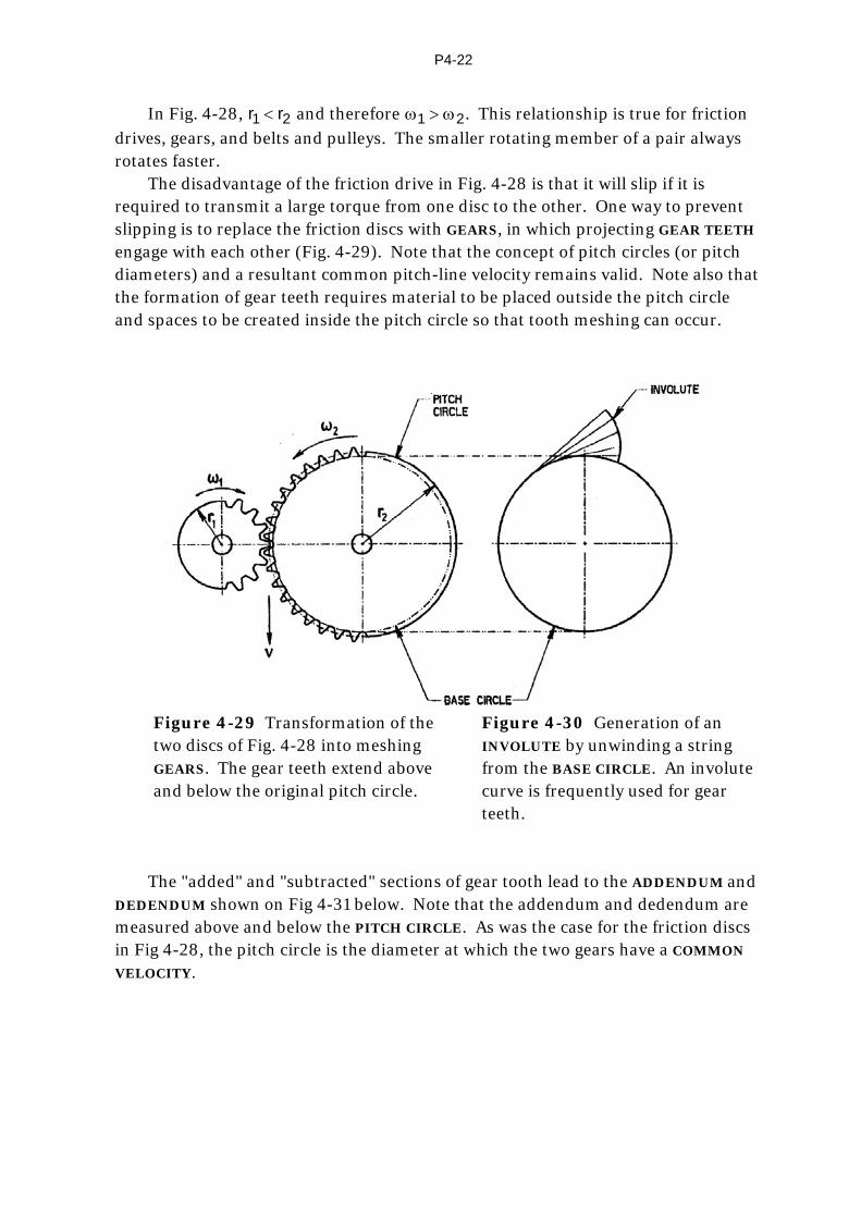
In Fig. 4-28, r r1 2< and therefore ω ω1 2> . This relationship is true for friction drives, gears, and belts and pulleys. The smaller rotating member of a pair always rotates faster.
The disadvantage of the friction drive in Fig. 4-28 is that it will slip if it is required to transmit a large torque from one disc to the other. One way to prevent slipping is to replace the friction discs with GEARS, in which projecting GEAR TEETH engage with each other (Fig. 4-29). Note that the concept of pitch circles (or pitch diameters) and a resultant common pitch-line velocity remains valid. Note also that the formation of gear teeth requires material to be placed outside the pitch circle and spaces to be created inside the pitch circle so that tooth meshing can occur.
Figure 4-29 Transformation of the
two discs of Fig. 4-28 into meshing GEARS. The gear teeth extend above and below the original pitch circle.
Figure 4-30 Generation of an INVOLUTE by unwinding a string from the BASE CIRCLE. An involute curve is frequently used for gear teeth.
The "added" and "subtracted" sections of gear tooth lead to the ADDENDUM and
DEDENDUM shown on Fig 4-31 below. Note that the addendum and dedendum are measured above and below the PITCH CIRCLE. As was the case for the friction discs in Fig 4-28, the pitch circle is the diameter at which the two gears have a COMMON
VELOCITY.

P4-23
Figure 4-31 Gear terminology for spur gears. De Garmo, E P, Materials and Processes in Manufacture 5E, 1979, Collier Macmillan, page 796.
Fig. 4-31 gives the nomenclature for a SPUR GEAR. Spur gears have straight
teeth running perpendicular to the axis of rotation. The BASE CIRCLE, identified in Fig 4-31, is an important characteristic of gears
since, in the case of INVOLUTE GEARS, it is the diameter from which the INVOLUTE
CURVE springs. In Fig 4-31, the dedendum is shown as extending down to the ROOT
CIRCLE, which includes a small additional clearance for the teeth of the meshing gear.
2.2 Tooth form
There are special requirements for the shape of the teeth on the two meshing gears if they are to run together satisfactorily and turn the two members at CONSTANT
VELOCITY. Tooth profiles which do not meet this requirement result in acceleration/deceleration as each gear tooth comes into mesh, causing vibration and wear. One tooth form which meets these requirements and is very widely used in industrial gearing is the INVOLUTE profile.
An INVOLUTE CURVE is formed by "unwinding" a string from a cylinder (Fig. 4-30), where the cylinder forms the BASE CIRCLE of that involute. Tooth profiles other than involute are possible and have been used. For example, CYCLOIDAL gear teeth are widely used in clocks and watches because they transmit power very efficiently at the low speeds which occur in clocks.

P4-24
2.3 Gear configurations
Figure 4-32a Some of the simple gearsets which are in common use. Bell, Peter C (Ed), Mechanical Power Transmission, 1971, Collier Macmillan, ISBN 333 125 460, page 26.

P4-25
Figure 4-32b Views of other types of gearsets. Grant, H E, Engineering Drawing with Creative Design, 2E, McGraw Hill 1968, page 165.

P4-26
Figs 4-32a and b show some of the different types of gearsets which are in common use. Note carefully how the different gear types allow the gear axes to be in different directions to suit particular applications.
SPUR GEARS (Fig 4-32a) are usually limited to a speed ratio of about 5:1 whereas WORM GEARS can achieve a ratio of 100:1 or greater in a single stage. The axes of SPIRAL GEARS (seen in 4-32a and 4-32b) can be at angles other than the 90° shown. The axes of SPIRAL BEVEL GEARS meet at a point, while the axes of HYPOID
GEARS do not intersect. A configuration such as the FRACTIONAL GEAR formerly found use in applications such as the steering box of motor vehicles, where the front wheels needed to be turned through much less than 360°. HYPOID GEARSETS came into common use in rear-wheel-drive motor cars because the lower centre of the HYPOID PINION allowed the drive shaft (tailshaft) to be placed lower and therefore to intrude less into the passenger space.
2.4 Uses of gears
1. They transmit TORQUE without slipping. High torque and high speed are possible.
2. They are positioning devices. There is always a positive relationship between gear-driven components, e.g. an engine camshaft must be driven at exactly half engine speed so that the valves always open at the correct point in the engine cycle. This can be achieved by the use of gears.
3. Rotary to reciprocating motion (and vice versa) is possible, e.g. the RACK and PINION used in motor car steering systems. (A relatively recent development is the VARIABLE RATIO RACK AND PINION, an Australian invention now used in many upmarket cars.)
4. Gears reverse the direction of rotation (see Fig. 4-28, 4-29). Naturally, two such reversals result in rotation in the original direction.
5. Gears change shaft speed, ω, and torque T (refer to Fig. 4-33).
Fig. 4-33 Speed and torque relationships for two meshing gears.
P4-27
Since, in general, power P = Tω, then for two gears in mesh
P = T1ω1 = T2ω2
Also, from Fig 4-28, v = r1ω1 = r2ω2
Hence P = T1 v/r1 = T2 v/r2
and T1/r1 = T2/r2
or T1/T2 = r1/r2 = ω2/ω1
In summary, a pair of gears may be used to reduce rotational speed or to
increase rotational speed, depending on which gear is the DRIVING gear and which the DRIVEN. However, the statements in the table below are true for both conditions.
PINION GEAR or WHEEL
Smaller gear of pair (fewer teeth) Larger gear of pair (more teeth)
Rotates faster (larger ω) Rotates slower (smaller ω)
Runs at lower torque Runs at higher torque
2.5 Advantages of gears
1. They are compact, allow short centre distance.
2. They are quiet in operation (if good quality gears).
3. They have long life provided they are properly designed, adequately lubricated, and operate in a clean environment.
4. A wide variety of configurations is available. Shafts may be: Parallel – spur or helical gears Perpendicular - intersecting axes – spiral bevel, straight bevel - non-intersecting axes – hypoid, worm At any angle - intersecting – spiral bevel, straight bevel - non-intersecting axes – spiral gears
2.6 Disadvantages of gears
1. They are precision components requiring special machines to manufacture. Initial cost may therefore be high compared with other power-transmitting elements.

P4-28
2. They require accurate location and alignment.
3. They require good lubrication.
4. They require clean operating conditions.
5. From 3. and 4., they require a sealed housing which may be expensive.
6. Centre distances are inherently short. Gears are not suitable for drives requiring long centre distances.
7. There is a restriction on the maximum ratio for a pair of gears in mesh, say 5:1 for spur gears. This restriction is imposed because of problems which arise in manufacturing the pinion (small gear), e.g. undercutting.
2.7 Gear trains
Fig 4-34 An example of a compound gear train. In real-life gear trains, each shaft carrying a gear must be mounted in bearings in order to keep the gears in mesh. For clarity, bearings and the housing in which the bearings are mounted are not shown in this diagram. http://www.brighthub.com/engineering/mechanical/articles/66020.aspx?image=68312
In many applications using the spur gears shown in Fig 4-34, speed changes greater than 5:1 are required. This may be achieved by two or more stages of reduction, as shown in Fig. 4-34.
The system works by having a large and a small gear on the same shaft, and therefore running at the same angular velocity, ω.
Fig. 4-34 actually shows a SPEED-UP DRIVE. Let the purple gear on the input shaft (top left) have say 100 teeth, meshing with the blue gear of say 50 teeth on the INTERMEDIATE SHAFT. This gives a SPEED INCREASE of 100/50 = 2/1. The red gear of say 75 teeth is also located on the intermediate shaft and therefore runs at

P4-29
the same speed as the first blue gear. The red gear having 75 teeth meshes with the second blue gear of say 25 teeth on the output shaft. The second speed increase is 75/25 = 3/1. The overall speed increase is therefore
10050
×7525
=61
Note that, as speed is increased by a factor of 6, the theoretical torque at the
output shaft is 6 times smaller than at the input. In practice, there will be losses due to mechanical inefficiencies (friction) and the actual output torque will be lower than predicted by this simple theory. Note also that since the output torque is lower, the output shaft diameter would in all probability be smaller than that of the input shaft. Further, if the input and output ends of the drive are interchanged, the drive becomes a speed reducing drive with the higher torque at the output end – the more usual configuration.

P4-30
2.8 Commercial gearboxes
Figure 4-35 Examples of some large speed-reducing gearboxes used in industry. Many such gearboxes are specially designed to suit particular applications. Note the stages used to achieve a large speed reduction, similar to the methods used in Fig 4-34. Note also the increase in shaft diameter to increase strength as speed is reduced and torque is increased. Three of these gearboxes are shown with top housings and side covers removed so that the internal arrangement of gears and bearings can be seen. Before being used, the top housings must be bolted into place, also all side covers and seals, and the housings filled with oil to the correct level. The fourth gearbox (lower right) is shown partially sectioned so that details of typical housings, bearings, shafts and bearing covers can be seen. Reproduced from Bell, Peter C (Ed), Mechanical Power Transmission, Macmillan, 1971, pages 27-29.
P4-31
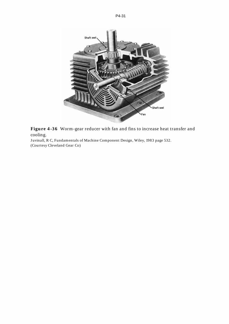
Figure 4-36 Worm-gear reducer with fan and fins to increase heat transfer and cooling. Juvinall, R C, Fundamentals of Machine Component Design, Wiley, 1983 page 532. (Courtesy Cleveland Gear Co)