Embed Size (px)
Citation preview

Part 5 – Appendices and Glossary

This page intentionally left blank.

Part 5 Appendix A
January 2010 Function Point Counting Practices Manual A-1
Appendix A: Functional Size Calculation Table
Introduction Appendix A includes a table to facilitate measuring functional size. Contents This appendix includes the following table:
Topic Page Functional Size Calculation Table A-2
Appendix A: Functional Size Calculation Table Part 5 – Appendices and Glossary
A-2 Function Point Counting Practices Manual January 2010
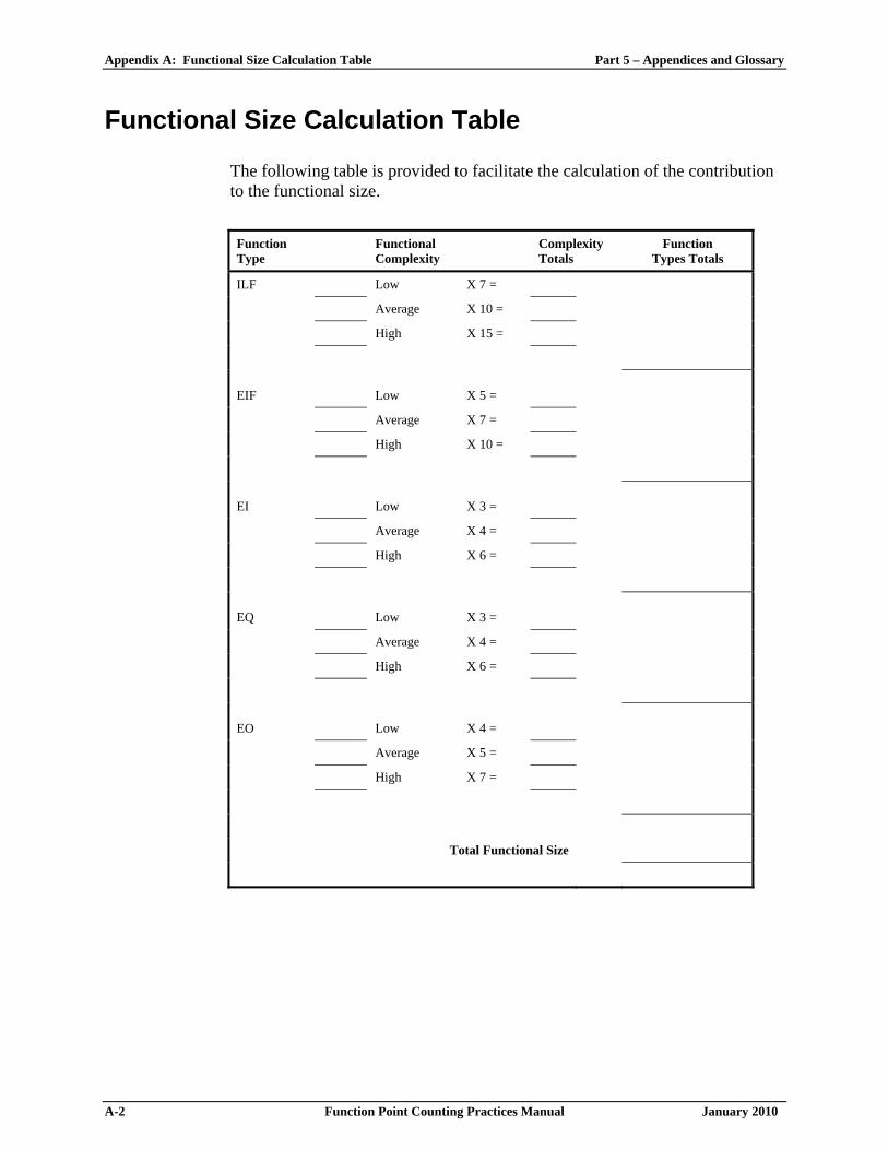
Functional Size Calculation Table
The following table is provided to facilitate the calculation of the contribution to the functional size.
Function Type
Functional Complexity
Complexity Totals
Function Types Totals
ILF Low X 7 =
Average X 10 =
High X 15 =
EIF Low X 5 =
Average X 7 =
High X 10 =
EI Low X 3 =
Average X 4 =
High X 6 =
EQ Low X 3 =
Average X 4 =
High X 6 =
EO Low X 4 =
Average X 5 =
High X 7 =
Total Functional Size
Part 5 Appendix B
January 2010 Function Point Counting Practices Manual B-1
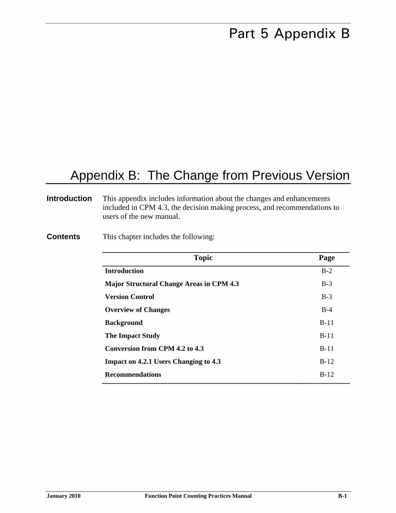
Appendix B: The Change from Previous Version
Introduction This appendix includes information about the changes and enhancements included in CPM 4.3, the decision making process, and recommendations to users of the new manual.
Contents This chapter includes the following:
Topic Page
Introduction B-2
Major Structural Change Areas in CPM 4.3 B-3
Version Control B-3
Overview of Changes B-4
Background B-11
The Impact Study B-11
Conversion from CPM 4.2 to 4.3 B-11
Impact on 4.2.1 Users Changing to 4.3 B-12
Recommendations B-12

Appendix B: The Change from Previous Version Part 5 – Appendices and Glossary
B-2 Function Point Counting Practices Manual January 2010
Introduction
Since the release of IFPUG Counting Practices Manual (CPM) 4.2 in 2004, the Counting Practices Committee (CPC) has created a new version of Part 1 (rules) to replace ISO Standard (ISO 20926:2004); i.e., IFPUG CPM 4.1 Unadjusted. The creation of the new ISO Standard required changes to the text in the remaining parts (the implementation guide) to retain consistency. When revising the CPM, the CPC process is as follows: 1. The issue is submitted to the CPC by the membership. 2. The issue is assigned to CPC members for research. 3. The CPC reviews and discusses the issue. 4. The CPC presents the proposed solution to the membership. 5. An impact study is initiated. 6. The final decision is made. 7. The IFPUG membership is informed of the decision through MetricViews and IFPUG
conference presentations. 8. Changes become effective in a new CPM. 9. Case Studies are revised to reflect the new CPM.

Part 5 – Appendices and Glossary Appendix B: The Change from Previous Version
January 2010 Function Point Counting Practices Manual B-3
Major Structural Change Areas in CPM 4.3
The major structural change areas in CPM 4.3 are: • Replace existing Part 1 with the new ISO Standard (ISO/IEC 20926:2010) • Created The Bridge - Applying the IFPUG Functional Size Measurement Method (now Part
2) which provides guidance in applying the process and rules as defined in the ISO Standard (now Part 1)
• Amend the remaining parts to be consistent with the revised Part 1 • Counting Practices (Part 3) • Examples (Part 4) • Appendices and Glossary (Part 5)
Version Control
The CPC has chosen to name this version of the IFPUG CPM 4.3 rather than 4.2.2 or 5.0 for two reasons: • A version of 4.2.2 would suggest some corrected typos only; version 4.3 draws more
attention to the rewrite of part 1. • A version of 5.0 would suggest a major change of the rules. CPM 4.3 is still an evolution of
the Albrecht methodology that forms the basis of all previous IFPUG CPMs. It provides further clarification of the previous version.

Appendix B: The Change from Previous Version Part 5 – Appendices and Glossary
B-4 Function Point Counting Practices Manual January 2010
Overview of Changes
In addition to replacing the existing Part 1 with the ISO Standard, other minor clarifications have been included in CPM 4.3. To facilitate users who wish to align their existing CPM written in a foreign language, all changes have been listed below.
Part 1: Process and Rules In order for the IFPUG Implementation Guide to be compliant with the revised ISO FSM Standard (ISO/IEC 14143-1:2007), some of the terminology had to be revised. The rules and guidelines are essentially unchanged; however, the sequence of actions and the wording has changed slightly. It is not expected that functional sizes would change. All chapters in Part 1 (now Part 2) include wording changes, additional examples and guidance in order to be consistent and comply with the updated ISO FSM Standard, which was released in 2007 and is now Part 1. The GSCs and Value Adjustment Factor have been removed from this Part and are included in the appendices in order to comply with the ISO FSM Standard, which does not recognize them to be part of the FSM. Additional details are indicated by chapter below.
Part 1, Chapter 1: Introduction The title of this chapter has changed to “The Bridge - Applying the IFPUG Functional Size Measurement Method”. Chapter 1 contains only an introduction; the changes reflect the contents of the remaining chapters in the new Part 2.
Part 1, Chapter 2: Overview of Function Point Analysis The title of this chapter has changed to “IFPUG FSM Method Overview”. There are extensive wording changes in order to be consistent and comply with the updated ISO FSM Standard. The following definitions and rules have been slightly reworded: The procedural diagram and guidelines in this chapter have been changed to reflect that the first step in the function point counting procedure is to gather the available documentation, in accordance with the ISO FSM Standard. The functional size now represents a size of the software derived by quantifying the functional user requirements replacing the term “unadjusted function points”. Any discussion of “unadjusted” or “adjusted” is now included in the appendices in order to comply with the ISO FSM Standard, which does not recognize the GSCs or VAF to be part of the FSM.
Part 1, Chapter 3: User View The title of this chapter has changed to “Gather Available Documentation”. This chapter presents the concept of the user’s role and the approach to sizing during the life cycle of an application; however, virtually all the chapter is unchanged except for the title.

Part 5 – Appendices and Glossary Appendix B: The Change from Previous Version
January 2010 Function Point Counting Practices Manual B-5
Part 1, Chapter 4: Determine Type of Count The title of this chapter has changed to “Determine Type of Count”. Revised wording has been provided for the definitions of development project function point count, enhancement project function point count and application function point count to be consistent and comply with the updated ISO FSM Standard.
Part 1, Chapter 5: Identify Counting Scope and Application Boundary The title of this chapter has changed to “Determine the Counting Scope and Boundary and Identify Functional User Requirements”. There are some minor wording changes to be consistent and comply with the updated ISO FSM Standard, but the great majority of the chapter is unchanged.
Part 1, Chapter 6: Count Data Functions The title of this chapter has changed to “Measure Data Functions” to reflect that the rules are actually contained in the new Part 1 and to reflect that this chapter provides implementation guidance for measuring data functions. The rules contained are repeated from Part 1 to make it easier to utilize and to avoid a requirement to flip back and forth between parts.
Part 1, Chapter 7: Count Transactional Functions The title of this chapter has changed to “Measure Transactional Functions” to reflect that the rules are actually contained in the new Part 1 and to reflect that this chapter provides implementation guidance for measuring transactional functions. Just as in Chapter 6, the rules contained are repeated from Part 1 to make it easier to utilize and to avoid a requirement to flip back and forth between parts. Specific items include: • Additional guidance and clarification on the FSM rules for elementary processes • Simplified DET and FTR rules
Part 1, Chapter 8: Determine Value Adjustment Factor The entire content of this chapter has been moved to Appendix C in order to align the Implementation Guide with the IFPUG FSM which does not include the GSCs and VAF.
Part 1, Chapter 9: Calculate Adjusted Function Point Count The formulas previously contained in this chapter have been moved to Appendix C and Part 3 Chapter 4 Enhancement and Maintenance Activity in order to align the Implementation Guide with the IFPUG FSM which does not include the GSCs and VAF.

Appendix B: The Change from Previous Version Part 5 – Appendices and Glossary
B-6 Function Point Counting Practices Manual January 2010
Part 2: Counting Practices All chapters in Part 2 (now Part 3) include slight wording changes in order to be consistent with the reorganization of Part 1 and/or to comply with the updated ISO FSM Standard. A new chapter (Chapter 5) was added to provide insight into counting Data Conversion Activity. Additional details are indicated by chapter below.
Part 2, Chapter 1: Code Data IFPUG FPA is compliant with this ISO FSM Standard. The decision to not count Code Data and to create the Code Data chapter in Part 2 of CPM 4.2 originated from the requirements in the ISO FSM Standard (ISO/IEC 14143-1:1998) to not count technical and quality requirements. In 2007 ISO released a new version of the FSM Standard (ISO/IEC 14143-1:2007). Consequently, the Code Data chapter needed to be updated to reflect wording changes in the ISO FSM Standard. There are no changes in rules or guidance in this chapter, but there are slight wording changes to comply with the updated ISO FSM Standard. • Added the ISO definition of Functional Size • Updated the definition of Functional User Requirements • Replaced the terms Quality Requirements and Technical Requirements by the ISO term Non-
Functional User Requirements and included the ISO definition for this concept • The section Methodology has been slightly reworded to reflect the changes in the step
“Identify Logical Files” in Chapter 2: Logical Files below
Part 2, Chapter 2: Logical Files This chapter was created in CPM 4.2 to provide counting practices and additional guidance in identifying and assessing the Logical Files. In CPM 4.3, Part 1 has been replaced by the updated IFPUG FPA ISO Standard Some changes to the ISO FSM Standard have a (minor) consequence for the Logical Files chapter: • In the process of identifying Logical Files, the previous step 1 (“Filter Out Code Data Before
Assessing Logical Files”) has now become a part of step 1 “Identify Logical Files”, which is a more appropriate place
• Furthermore, the previous step 2 (“Identify Logical Files and Classify”) has been decomposed into two steps “1. Identify Logical Files” and “2. Classify Logical Files”
• Steps 3 and 4 (identifying RETs and DETs) have been interchanged • The substeps of step 1 have been better visualized by effectively naming them substeps These changes in structure have some (minor) consequences for the structure of the Logical Files chapter.

Part 5 – Appendices and Glossary Appendix B: The Change from Previous Version
January 2010 Function Point Counting Practices Manual B-7
This is especially true for the interchanging of the steps Identifying DETs and Identifying RETs. That made it necessary to interchange the pages related to these steps. It was also necessary to combine the tables “Considering Record Element Types in Conjunction with Logical Files via Entity (In-)Dependence” (CPM 4.2, page 2-34) and “Considering Data Element Types in Conjunction with Logical Files via Entity (In-)Dependence” (CPM 4.2, page 2-46) into one new table “Considering Data Element Types and Record Element Type below in Conjunction with Logical Files via Entity (In-)Dependence” There are slight wording changes to comply with the updated ISO FSM Standard (ISO/IEC 14143-1:2007) as explained in more detail in the section above, dedicated to Part 2, Chapter 1 Code Data. Quality Requirements and Technical Requirements were replaced by the new ISO term Non-Functional User Requirements. None of these changes in structure and wording are expected to have any influence in the outcome of any counts.
Part 2, Chapter 3: Shared Data This chapter was created in CPM 4.2 to provide counting practices and additional guidance in identifying and assessing data shared between applications. The only changes to this chapter were two references to other parts of the CPM which are now different.
Part 2, Chapter 4: Enhancement Projects and Maintenance Activities This chapter was created in CPM 4.2 to provide counting practices and additional guidance in applying function point analysis to post development activities. The enhancement project count, first introduced in Part 1, Chapter 9 of CPM 4.1, is now covered entirely (including applicable formulas) in this chapter. In addition to updates for references to other parts of the CPM, the definitions and primary examples for each of the forms of processing logic were set to be consistent with those in the new Part 2. Terms were also made consistent with Parts 1 and 2 such as changing “field” to “attribute”. Specific changes to the Processing Logic section in this chapter include the following:
3. Equivalent Values: Changed the example in response to IFPUG Bulletin Board comments.
4. Data Filtering: Modified existing example to exclude counting a change involving only the substitution or addition of values and added three new examples in response to IFPUG Bulletin Board comments.
11. Prepare and present information outside the boundary: Added three new examples to reflect CPC responses to IFPUG Bulletin Board comments.

Appendix B: The Change from Previous Version Part 5 – Appendices and Glossary
B-8 Function Point Counting Practices Manual January 2010
12. Accept information entering the boundary: Added two new examples to reflect CPC responses to IFPUG Bulletin Board comments.
13. Sorting: Added two new examples to reflect CPC responses to IFPUG Bulletin Board comments.
In Considerations and Hints, we added discussion regarding deleted functions and moved the hints on GSCs to Appendix C where the optional GSCs and VAF are covered. In the Enhancement vs. Maintenance section, any reference to GSCs has been prefaced with “optional”.
Part 2, Chapter 5: Data Conversion Activity (new chapter) This new chapter addresses the functionality to be evaluated when there are requirements to migrate or convert data in conjunction with a new development or enhancement project or to move an application to a different platform. Part 4 of the CPM provides other examples of the data functions and of transactional functions for data conversion.
Part 3: Examples All chapters in Part 3 (now Part 4) included revisions to the rule boxes throughout this section to be consistent with wording changes in the data function, elementary process and transactional function rules. Additional details are indicated by chapter below.
Part 3, Chapter 1: Data Function Counting Examples • ILF Example: Audit Data for Inquiries and Reports – Removed references to Employee
Security Maintenance from the Data Flow Diagram because it was confusing and wasn’t properly explained
• ILF Example: Report Definition – Expanded upon explanation, addressing why Report Definition is not an instance of code data
• ILF Example: Shared Application Data – Clarified the example to make it clear that the security described in this example is not application security (i.e., determining what the user can access within the application)
• EIF Example: Providing Data to Other Applications – Expanded upon explanation, addressing why Currency Conversion is not an instance of code data
• EIF Example: Help Application – Expanded upon explanation, addressing why Help is not an instance of code data; also explained why Window Help and Field Help are separate data functions
Part 3, Chapter 2: Transactional Function Counting Examples • EP Example: New Employee/Dependent Data – Expanded upon explanation, addressing
why sending the file to the Benefits System is a separate elementary process • EP Example: Batch Employee Data Feed – This new example illustrates that producing
batch error reports and statistical reports are not separate elementary processes • EP Example: Assign Employee to Job - This new example illustrates the evaluation of
similar elementary processes to determine whether they are unique

Part 5 – Appendices and Glossary Appendix B: The Change from Previous Version
January 2010 Function Point Counting Practices Manual B-9
• EP Example: Assign Employee to Job - This new example illustrates two similar Elementary Processes that are counted as unique transactions
• EI Example: EI with Attributes Retrieved from an EIF – This new example illustrates an EI with attributes retrieved from an EIF that do not cross the boundary
• EI Example: EI Delete – This new example illustrates counting DETs for a delete transaction
• EI Example: Add Window Security – This new example illustrates counting functionality to maintain application security
• EO Example: EO Triggered without Data Entering the Boundary – Renamed this example to eliminate confusion
• EQ Example: EQ Triggered without Data Entering the Boundary – Renamed this example to eliminate confusion
• EQ Example: Additional Help Functionality – This new example illustrates counting additional help functionality
• EQ Example: Security for User Access – This new example illustrates treatment of application security
• EQ Example: Application Logon – This new example illustrates counting the logon function
Part 4: Appendices and Glossary All chapters in Part 4 (now Part 5) included revisions. Details are indicated by chapter below.
Part 4, Appendix A: Calculation Tables Minor wording changes to eliminate use of the term unadjusted.
Part 4, Appendix B: The Change from Previous Version This new chapter includes the following: • The major functional change areas in CPM 4.3 • Version control information • An overview of the changes by chapter • The background of the change process • The impact study process • The impact of the changes on 4.3 users • Conversion from CPM 4.2.1 to 4.3 • Recommendations for users changing from 4.2.1 to 4.3
Part 4, Appendix C: Reader Request Form The Reader Request Form was eliminated. Readers can suggest changes by sending an email to the CPC ([email protected]). Appendix C title was changed to Adjusted Functional Size and now contains guidance on applying the General Systems Characteristics and Value Adjustment Factor. It contains all formulas which use the GSCs and VAF.

Appendix B: The Change from Previous Version Part 5 – Appendices and Glossary
B-10 Function Point Counting Practices Manual January 2010
Part 4, Glossary The following new terms have been added to the glossary: • Adjusted application functional size (aAFP) • Consistent state • Adjusted application functional size after
enhancement projects (aAFPA) • Development project functional size
• Adjusted development project functional size (aDFP)
• Enhancement project functional size
• Adjusted enhancement project functional size (aEFP)
• Functional size
• Application functional size • Meaningful • Arranging • Primary Intent • Base functional component • Self-contained • Boundary • Sorting • Boundary of the application • Unadjusted functional size The following terms have been revised in the glossary: • Adaptive maintenance • Functional complexity • Adjusted function point count (AFP) * • Functional user requirements • Application • Function point (FP) • Application boundary • Function point analysis • Application function point count • Function point count • Contribution • Function type • Control information • Maintained * • Conversion functionality • Maintenance • Corrective maintenance • Multiple sites GSC • Counting Scope • Perfective maintenance • Derived data • Purpose of the Count • Development * • Record element type (RET) • Development project function point count (DFP) • Technical attribute • Enhancement * • Transactional functions • Enhancement project function point count (EFP) • Unadjusted function point count (UFP) • Entity Dependence • User • Entity Independence • User recognizable • File system • User view • File type referenced (FTR) * Denotes entries where the term name was changed (e.g., Adjusted function point count (AFP) became adjusted functional size).

Part 5 – Appendices and Glossary Appendix B: The Change from Previous Version
January 2010 Function Point Counting Practices Manual B-11
Background
The CPC internal decision making process is governed by a set of CPM characteristics (meta rules) selected and voted on by the IFPUG board and the CPC. Those guiding principles in order of importance are: 1. It should be possible to model the correlation of software size (derived using the CPM) with
other attributes (e.g., effort, defects, cost, etc.). 2. The CPM contains a consistent set of rules. 3. Function Point Analysis results are consistent between different counters using the CPM. 4. The CPM provides rules on how to size a functional need that is defined and agreed upon by
user(s) and IT. 5. Function Point Analysis results using the CPM can be a contributing factor in estimation. 6. The CPM is an Albrecht based method. 7. Function Point Analysis using the CPM is easy. 8. Function Point Analysis using the CPM is fast.
The Impact Study
The IFPUG function point analysis (FPA) process and rules are concise and easy to use. To reflect that, and to make the Counting Practices Manual (CPM) even more attractive as a reference manual, the Counting Practices Committee (CPC) restructured CPM 4.3 to comply with ISO formatting Standards. Besides that, release 4.3 contains minor modifications and provides new examples, clarification and enhanced interpretations for existing rules that will further increase inter-counter consistency. To measure the effectiveness of this new version an impact study was performed by 44 Certified Function Point Specialists who had no direct connection with the Counting Practices Committee. These volunteers were asked to count a case study using both CPM 4.2.1 and CPM 4.3. Their results were identical using both versions. These participants counted projects that they had performed under the CPM 4.2.1 rules using the new CPM 4.3. In total over 100 counts including a mix of development, application, enhancement and conversion were considered. The resulting conversion factor was found to be 1.0; i.e., no difference.
Conversion from CPM 4.2 to 4.3
Since existing practices vary, each organization must analyze its own practices to determine how it is impacted. Some organizations may find a conversion factor that is applicable across their portfolio. Others may find that the conversion factor varies across different types of systems, and in some cases systems will need to be recounted.

Appendix B: The Change from Previous Version Part 5 – Appendices and Glossary
B-12 Function Point Counting Practices Manual January 2010
Impact on 4.2.1 Users Changing to 4.3
Although an additional certification will not be required for counters for CPM 4.3, the certification tests will be updated for conformance to 4.3.
Recommendations
The CPC recommends the following actions for users switching from CPM 4.2 to 4.3: • Update all in-house developed training materials for conformance. • Ensure all counters within your organization have been appropriately trained in the
differences between 4.2 and 4.3. • Check all vendor offered training materials for version certification. • Notify anyone in your organization involved with functional size measurements of the
change and make the new manual available to them. • Review all counting tools for your users, both automated and manual, for IFPUG 4.3 version
certification, if applicable, and modifications to conform to 4.3 counting rules. • If providing services based upon Function Points, ensure the contract wording is reviewed to
determine which version of the CPM manual will be used; amend as necessary. • Specify on the documentation for each functional size measurement performed, and with the
results, which version of the CPM was used. • Make sure to specify which version of the IFPUG CPM was used for counting when
submitting data for benchmarking either to your own benchmark database, the IFPUG Benchmarking committee, or ISBSG.
• Update all internal guidelines and other local documents related to 4.2 to version 4.3.

Part 5 Appendix C
January 2010 Function Point Counting Practices Manual C-1
Appendix C: Adjusted Functional Size Introduction This chapter explains the General Systems Characteristics (GSCs) and Value
Adjustment Factor (VAF).
Note: Applying the GSCs, calculating the VAF, and calculating the adjusted functional size is not included in the IFPUG FSM and is considered optional in the IFPUG CPM.
However when reporting the functional size that is measured using the IFPUG Method, the size reported is that derived prior to any adjustment. The reported size is in units of FPs. When using sizes reported from other sources, first determine if they have been ‘adjusted’ or are they ‘unadjusted’. Failure to do so could result in errors when comparing or using the two sets of results. Always denote whether the functional size being reported is ‘adjusted’ (aFP) or ‘unadjusted’ (FP).
Contents This chapter includes the following sections:
Topic Page
Steps for Calculating Adjusted Functional Size C-3
Value Adjustment Factor Determination C-4
Guidelines to Determine Degree of Influence for GSCs C-6
Value Adjustment Factor Calculation Table C-31
Adjusted Development Project Function Point (aDFP) C-32
Formula: Adjusted Development Project Functional Size (aDFP) C-32
Example: Adjusted Development Project Functional Size (aDFP) C-33

Appendix C: Adjusted Functional Size Part 5 – Appendices and Glossary
C-2 Function Point Counting Practices Manual January 2010
Topic Page
Adjusted Enhancement Project Functional Size (aEFP) C-37
Formula: Adjusted Enhancement Project Functional Size (aEFP) C-38
Example: Adjusted Enhancement Project Functional Size (aEFP) C-39
Adjusted Application Functional Size (aAFP) C-43
Formula: Initial Adjusted Application Functional Size (aAFP) C-43
Formula: Adjusted Application Functional Size After Enhancement Projects (aAFPA)
C-44
Example: Application Count C-45

Part 5 – Appendices and Glossary Appendix C: Adjusted Functional Size
January 2010 Function Point Counting Practices Manual C-3
Steps for Calculating Adjusted Functional Size
The following list includes the function point analysis steps introduced in Part 1, extended to provide adjusted functional size.
Step Action
1 Determine the functional size using the rules in Part 1 and the implementation guidance in Part 2.
2 Determine the value adjustment factor in accordance with the guidance in this appendix.
3 Calculate the adjusted functional size in accordance with the formulas in this appendix.
The remainder of this chapter presents the General System Characteristics, the
resulting Value Adjustment Factor followed by the formulas to calculate the Adjusted Functional Size. Example calculations are included for each of the three types of function points counts:
• Development project
• Enhancement project
• Application

Appendix C: Adjusted Functional Size Part 5 – Appendices and Glossary
C-4 Function Point Counting Practices Manual January 2010
Value Adjustment Factor Determination
The value adjustment factor (VAF) is based on 14 general system characteristics (GSCs) that rate the general functionality of the application being measured. Each characteristic has associated descriptions that help determine the degree of influence of that characteristic. The degree of influence for each characteristic ranges on a scale of zero to five, from no influence to strong influence.
The 14 general system characteristics are summarized into the value adjustment factor. When applied, the value adjustment factor adjusts the unadjusted functional size +/-35 percent to produce the adjusted functional size.
Procedures to Determine the VAF The following steps outline the procedures to determine the value adjustment
factor.
Step Action 1 Evaluate each of the 14 general system characteristics on a scale from
zero to five to determine the degree of influence (DI).
2 Add the degrees of influence for all 14 general system characteristics to produce the total degree of influence (TDI).
3 Insert the TDI into the following equation to produce the value adjustment factor.
VAF = (TDI * 0.01) + 0.65
For example, the following value adjustment factor is calculated if there are three degrees of influence for each of the 14 GSC descriptions (3*14). VAF = (42 * 0.01) + 0.65
VAF = 1.07 A table to facilitate the calculation is included in this Appendix.

Part 5 – Appendices and Glossary Appendix C: Adjusted Functional Size
January 2010 Function Point Counting Practices Manual C-5
General System Characteristics The general system characteristics are a set of 14 questions that evaluate the
overall complexity of the application. The 14 general system characteristics are:
1. Data Communications 2. Distributed Data Processing 3. Performance 4. Heavily Used Configuration 5. Transaction Rate 6. On-line Data Entry 7. End-User Efficiency 8. On-line Update 9. Complex Processing 10. Reusability 11. Installation Ease 12. Operational Ease 13. Multiple Sites 14. Facilitate Change

Appendix C: Adjusted Functional Size Part 5 – Appendices and Glossary
C-6 Function Point Counting Practices Manual January 2010
Degrees of Influence Based on the stated user requirements, each general system characteristic
(GSC) must be evaluated in terms of its degree of influence (DI) on a scale of zero to five.
Score as System Influence
0 Not present or no influence 1 Incidental influence 2 Moderate influence 3 Average influence 4 Significant influence 5 Strong influence throughout
Guidelines to Determine Degree of Influence for GSCs
Each of the following general system characteristic descriptions includes guidelines to determine the degree of influence. Each guideline contains a definition of the GSC, rules for determining the score, and, in situations where the rule needs further clarification, hints have been provided to help apply the rules consistently across all platforms. Hints are not intended to cover all situations but are meant to provide additional guidance in determining the appropriate score.

Part 5 – Appendices and Glossary Appendix C: Adjusted Functional Size
January 2010 Function Point Counting Practices Manual C-7
1. Data Communications
Definition Data Communications describes the degree to which the application communicates directly with the processor. The data and control information used in the application are sent or received over communication facilities. Devices connected locally to the control unit are considered to use communication facilities. Protocol is a set of conventions that permit the transfer or exchange of information between two systems or devices. All data communication links require some type of protocol.
Score As Descriptions to Determine Degree of Influence
0 Application is pure batch processing or a stand-alone application.
1 Application is batch but has remote data entry or remote printing.
2 Application is batch but has remote data entry and remote printing.
3 Application includes on-line data collection or TP (teleprocessing) front end to a batch process or query system.
4 Application is more than a front-end, but supports only one type of TP communications.
Score
5 Application is more than a front-end, and supports more than one type of TP communications protocol.
Hints Protocol examples include FTP, dial-up, Token Ring, Ethernet, SNA, TCP/IP,
IPX/SPX, HTTP, XML, WAP, NTP, ICQ, and NETBEUI. This list should not be considered exhaustive.
Hints to
Rules 1 and 2
• Remote devices might include a 3270 terminal connected to a mainframe computer that allows only simple edits (numeric vs. alpha), or printers connected via parallel port (the user can specify where to direct the output).
• The entry of data does not involve reading or writing directly to an ILF. Data are entered on-line, but the transactions are stored in a temporary file for batch update of ILF(s) at a later time.

Appendix C: Adjusted Functional Size Part 5 – Appendices and Glossary
C-8 Function Point Counting Practices Manual January 2010
Hints to
Rule 3 • Simple business rules and minimal edits (e.g., alpha/numeric,
range check, required data, etc.) may be performed. When this data is eventually processed by the application, additional edits are performed.
• The entry of data does not involve reading or writing directly to an ILF. Data are entered on-line, but the transactions are stored in a temporary file for batch update of ILF(s) at a later time.
Hints to
Rule 4 • Data for the application is collected and may directly update
ILF(s) or be stored for future processing using an input device, which performs edits based on business rules.
• Only one communication protocol is used. Typically, when this data is processed by the application, no further edits are required.
• The entry of data involves reading or writing to an ILF.
• For example, client-server data entry or Internet data entry, but not both.
Hints to
Rule 5 • Same as 4, however, data collection is performed using
multiple telecommunication protocols.
• For example, client-server data entry and Internet data entry of the same transaction.
Typically • Batch applications receive a score of 0 to 3.
• On-line applications receive a score of 4.
• Web-based applications receive a score of 4 or 5.
• Real-time, telecommunication, or process control systems receive a score of 4 or 5.

Part 5 – Appendices and Glossary Appendix C: Adjusted Functional Size
January 2010 Function Point Counting Practices Manual C-9
2. Distributed Data Processing
Definition Distributed Data Processing describes the degree to which the application transfers data among physical components of the application. Distributed data or processing functions are a characteristic of the application within the boundary.
Score As Descriptions To Determine Degree of Influence
0 Data is not transferred or processed on another component of the system.
1 Data is prepared for transfer, then is transferred and processed on another component of the system, for user processing.
2 Data is prepared for transfer, then is transferred and processed on another component of the system, not for user processing.
3 Distributed processing and data transfer are on-line and in one direction only.
4 Distributed processing and data transfer are on-line and in both directions.
Score
5 Distributed processing and data transfer are on-line and are dynamically performed on the most appropriate component of the system.
Hints Distributed data processing by definition is not an application that is
contained on a central processor, which sends data to other applications. In a distributed environment, the application is viewed as requiring multiple components (hardware) on which certain processing or data resides. A knowledgeable user would usually recognize this configuration.
Hints to
Rule 0 • Presentation, processing, and I/O components are all in the
same place (i.e., stand-alone applications). Hints to
Rule 1 • Application downloads data to a user’s client machine, so the
user can use Excel or other reporting tools to prepare graphs and perform other analysis.
• Process that transfers data from mainframe to an external component for user processing. This transfer is performed using a simple protocol such as FTP.
• Transferred to a user for processing.
Appendix C: Adjusted Functional Size Part 5 – Appendices and Glossary
C-10 Function Point Counting Practices Manual January 2010
Hints to Rule 2
• Process that transfers data from mainframe to mid-tier. For example, processing with SAS-PC.
• Application sends data to client or server. This data is then processed or used to produce reports, etc. No data or confirmation is sent back to the client or server.
• Transferred to a component for processing. Hints to
Rule 3 • Data is sent between client and server in one direction only.
This data is then processed or used to produce reports, etc. by the receiving application. This data typically includes transactions that update an ILF on the client or server.
• For example – client-server or web-enabled applications. Hints to
Rule 4 • Data is sent between client and server in either direction.
This data is then processed or used to produce reports, etc. by the receiving application. This data typically includes transactions that update an ILF on the client or server.
• For example - client-server or web-enabled applications.
• The application runs under an operating system that automatically handles the allocation between components, however, the use of the operating system did not influence the design and implementation of the application.
Hints to
Rule 5 • The developer must consider special application software that
looks at multiple processors and runs the application on a specific type of processor. This is invisible to the user.
• The application runs under an operating system that automatically handles the dynamic allocation between components, and the use of the operating system specifically influenced the design and implementation of the application.
Typically • Many applications, including legacy applications, receive a score of 0.
• Primitive distributed applications that include batch applications in which data is not transferred on-line receive a score of 1 to 2.
• Client-server or web-based applications receive a score of 3 to 4.
• It is uncommon to score 5.
• There must be multiple servers or processors, each of which would be selected dynamically on the basis of its real-time availability to score 5.

Part 5 – Appendices and Glossary Appendix C: Adjusted Functional Size
January 2010 Function Point Counting Practices Manual C-11
3. Performance
Definition Performance describes the degree to which response time and throughput performance considerations influenced the application development.
Application performance objectives, stated or approved (or implied) by the user, in either response or throughput, influence (or will influence) the design, development, installation, and support of the application.
Score As Descriptions To Determine Degree of Influence
0 No special performance requirements were stated by the user.
1 Performance and design requirements were stated and reviewed but no special actions were required.
2 Response time or throughput is critical during peak hours. No special design for CPU utilization was required. Processing deadline is for the next business cycle.
3 Response time or throughput is critical during all business hours. No special design for CPU utilization was required. Processing deadline requirements with interfacing systems are constraining.
4 In addition, stated user performance requirements are stringent enough to require performance analysis tasks in the design phase.
Score
5 In addition, performance analysis tools were used in the design, development, and/or implementation phases to meet the stated user performance requirements.
Hints • GSCs 3, 4 and 5 are somewhat related. For this GSC, think in terms of
"How fast can we make the application go and how much did/does that impact the design, development, and/or implementation?"
• The users may require real time access to their data, stating or implying standards for response time and throughput capacity.
• Response time typically relates to interactive processing; throughput relates to batch processing.

Appendix C: Adjusted Functional Size Part 5 – Appendices and Glossary
C-12 Function Point Counting Practices Manual January 2010
Typically • Batch applications receive a score of 0 to 4.
• On-line (including interactive client-server or web-enabled) applications receive a score of 0 to 4.
• Web-based applications receive a score of 4 or 5.
• Most MIS on-line systems receive a score of 2.
• Real-time, telecommunication, or process control systems receive a score of 0 to 5.
• A score of 5 requires the use of performance analysis tools.
Part 5 – Appendices and Glossary Appendix C: Adjusted Functional Size
January 2010 Function Point Counting Practices Manual C-13
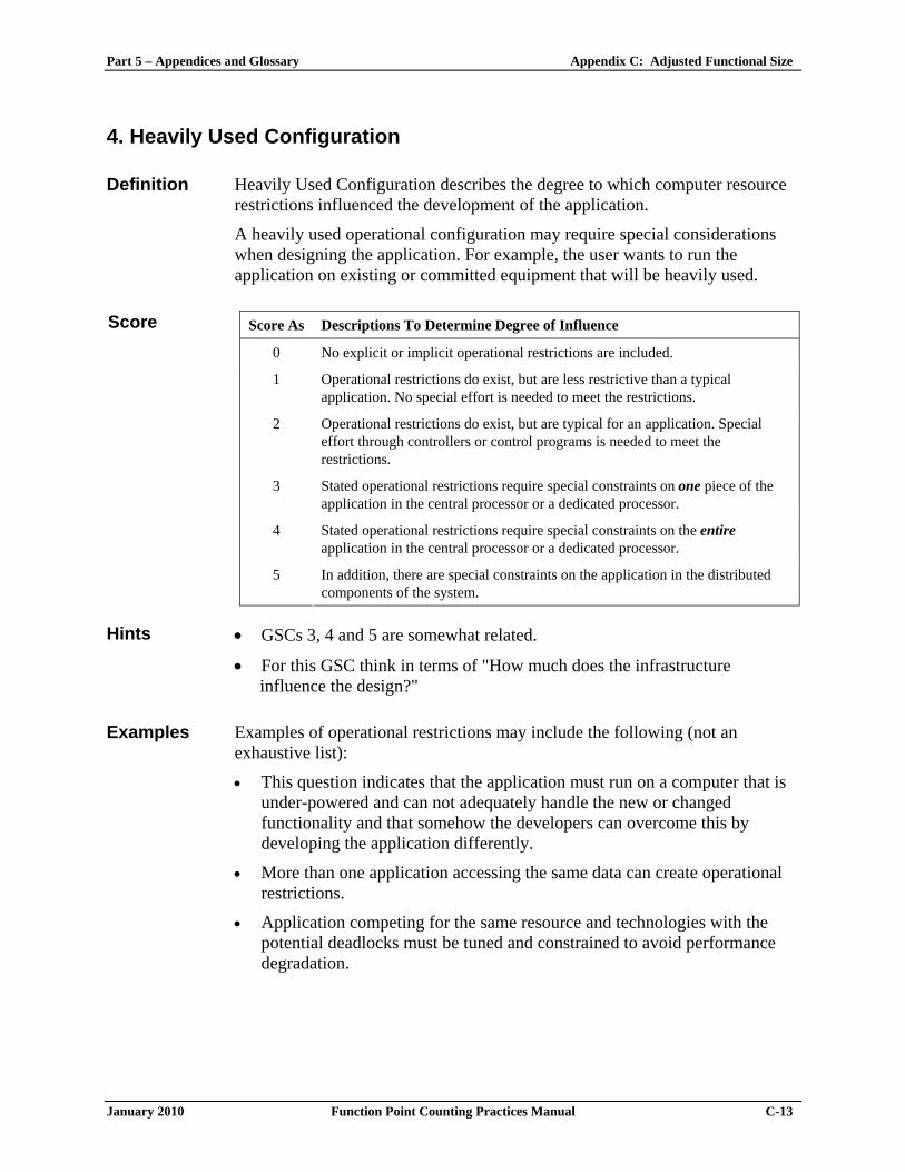
4. Heavily Used Configuration Definition Heavily Used Configuration describes the degree to which computer resource
restrictions influenced the development of the application.
A heavily used operational configuration may require special considerations when designing the application. For example, the user wants to run the application on existing or committed equipment that will be heavily used.
Score As Descriptions To Determine Degree of Influence
0 No explicit or implicit operational restrictions are included.
1 Operational restrictions do exist, but are less restrictive than a typical application. No special effort is needed to meet the restrictions.
2 Operational restrictions do exist, but are typical for an application. Special effort through controllers or control programs is needed to meet the restrictions.
3 Stated operational restrictions require special constraints on one piece of the application in the central processor or a dedicated processor.
4 Stated operational restrictions require special constraints on the entire application in the central processor or a dedicated processor.
Score
5 In addition, there are special constraints on the application in the distributed components of the system.
Hints • GSCs 3, 4 and 5 are somewhat related.
• For this GSC think in terms of "How much does the infrastructure influence the design?"
Examples Examples of operational restrictions may include the following (not an
exhaustive list):
• This question indicates that the application must run on a computer that is under-powered and can not adequately handle the new or changed functionality and that somehow the developers can overcome this by developing the application differently.
• More than one application accessing the same data can create operational restrictions.
• Application competing for the same resource and technologies with the potential deadlocks must be tuned and constrained to avoid performance degradation.

Appendix C: Adjusted Functional Size Part 5 – Appendices and Glossary
C-14 Function Point Counting Practices Manual January 2010
Typically • Most applications receive a score of 2.
• Client-server, web-enabled, real-time, telecommunication or process control systems receive a score of 3 to 5, but then you would need either a dedicated processor or multiple processors processing the same transactions and searching for the most expeditious means of processing.

Part 5 – Appendices and Glossary Appendix C: Adjusted Functional Size
January 2010 Function Point Counting Practices Manual C-15
5. Transaction Rate
Definition Transaction Rate describes the degree to which the rate of business transactions influenced the development of the application.
The transaction rate is high, and it influences the design, development, installation, and support of the application. Users may require what they regard as normal response time even during times of peak volume.
Score As Descriptions To Determine Degree of Influence
0 No peak transaction period is anticipated.
1 Low transaction rates have minimal effect on the design, development, and installation phases.
2 Average transaction rates have some effect on the design, development, and installation phases.
3 High transaction rates affect the design, development, and/or installation phases.
4 High transaction rate(s) stated by the user in the application requirements or service level agreements are high enough to require performance analysis tasks in the design, development, and/or installation phases.
Score
5 High transaction rate(s) stated by the user in the application requirements or service level agreements are high enough to require performance analysis tasks and, in addition, require the use of performance analysis tools in the design, development, and/or installation phases.
Hints • GSCs 3, 4 and 5 are somewhat related. For this GSC think in terms of
"How many transactions can be processed by the application in a given period of time?"
• Often this score is the same as the score for GSC 3 because transaction rates often influence performance requirements.
Typically • Batch applications receive a score of 0 to 3.
• On-line (including interactive client-server or web-enabled) applications receive a score of 0 to 4.
• Real-time, telecommunication, or process control systems receive a score of 0 to 5.
• A score of 5 requires the use of performance analysis tools.

Appendix C: Adjusted Functional Size Part 5 – Appendices and Glossary
C-16 Function Point Counting Practices Manual January 2010
6. On-line Data Entry Definition On-line Data Entry describes the degree to which data is entered or retrieved
through interactive transactions.
On-line User Interface for data entry, control functions, reports, and queries are provided in the application.
Score As Descriptions To Determine Degree of Influence
0 All transactions are processed in batch mode.
1 1% to 7% of transactions are interactive.
2 8% to 15% of transactions are interactive.
3 16% to 23% of transactions are interactive.
4 24% to 30% of transactions are interactive.
Score
5 More than 30% of transactions are interactive.
Hints • This refers to types of transactions not volumes.
• For example, if an application has 45 EIs, EOs, and EQs, what percent of the EIs, EOs, and EQs are accomplished via on-line transactions.
Typically • Batch applications receive a score of 0 to 1.
• On-line, real-time, telecommunication, or process control systems receive a score of 5.
• Most contemporary on-line (including interactive client-server or web-enabled) applications receive a score of 5.
• Batch systems with on-line features may have a lot of batch transactions, but there must be at least 71 percent batch to receive a score of less than 5.

Part 5 – Appendices and Glossary Appendix C: Adjusted Functional Size
January 2010 Function Point Counting Practices Manual C-17
7. End-User Efficiency
Definition End-User Efficiency describes the degree of consideration for human factors and ease of use for the user of the application measured.
The on-line functions provided emphasize a design for user efficiency (human factor/user friendliness). The design includes:
• Navigational aids (e.g., function keys, jumps, dynamically generated menus, hyper-links)
• Menus
• On-line help and documents
• Automated cursor movement
• Scrolling
• Remote printing (via on-line transmissions)
• Pre-assigned function keys (e.g., clear screen, request help, clone screen)
• Batch jobs submitted from on-line transactions
• Drop down List box
• Heavy use of reverse video, highlighting, colors, underlining, and other indicators
• Hard-copy documentation of on-line transactions (e.g., screen print)
• Mouse interface
• Pop-up windows
• Templates and/or defaults
• Bilingual support (supports two languages: count as four items)
• Multi-lingual support (supports more than two languages: count as six items)

Appendix C: Adjusted Functional Size Part 5 – Appendices and Glossary
C-18 Function Point Counting Practices Manual January 2010
Score As Descriptions To Determine Degree of Influence
0 None of the above.
1 One to three of the above.
2 Four to five of the above.
3 Six or more of the above, but there are no specific user requirements related to efficiency.
4 Six or more of the above, and stated requirements for user efficiency are strong enough to require design tasks for human factors to be included.
Score
5 Six or more of the above, and stated requirements for user efficiency are strong enough to require use of special tools and processes in order to demonstrate that the objectives have been achieved.
Hints • Use a convention of a score of 4 whenever the application is deployed in a
GUI environment (unless it scores 5).
• Usually only software environments that prepare applications for mass-market or non-technical users score 5, and only if they have ergonomics specialists and/or usability studies as part of their process.
Typically • Pure batch applications receive a score of 0.
• Character mode user interface receive a score of 1 or possibly a 2.
• GUI user interface to be used for low volume transactions receive a score of 3.
• GUI user interface to be used for high volume transactions and most Web Intranet user interfaces receive a score of 4 (requires design tasks for human factors).
• Web Internet user interfaces receive a score of 5 (requires special tools and processes to demonstrate that the objectives have been achieved).

Part 5 – Appendices and Glossary Appendix C: Adjusted Functional Size
January 2010 Function Point Counting Practices Manual C-19
8. On-line Update Definition On-line Update describes the degree to which internal logical files are
updated on-line.
The application provides on-line update for the internal logical files.
Score As Descriptions To Determine Degree of Influence
0 None.
1 On-line update of one to three control files is included. Volume of updating is low and recovery is easy.
2 On-line update of four or more control files is included. Volume of updating is low and recovery is easy.
3 On-line update of major internal logical files is included.
4 In addition, protection against data loss is essential and has been specially designed and programmed in the system.
Score
5 In addition, high volumes bring cost considerations into the recovery process. Highly automated recovery procedures with minimum human intervention are included.
Hints • On-line update usually requires a keyed file or database.
• Automatic recovery provided by the operating system counts if it impacts the application.
Typically • Pure batch applications receive a score of 0.
• On-line updates of files that modify the way an application processes or validates data receive a score of 1 or 2.
• On-line updates of user persistent data receive a score of 3.
• MIS applications receive a score of 3 or less.
• Most GUI type applications receive a score of 3 or above.
• Applications which use programmed recovery such as SQL roll back and commit receive a score of 4. Operational/routine backup is not considered protection against data loss.
• Applications required to recover data, reboot, or perform other self-contained functions in the event of a system error receive a score of 5. Recovery may require a human to press enter or perform some other minimal function to initiate this process.

Appendix C: Adjusted Functional Size Part 5 – Appendices and Glossary
C-20 Function Point Counting Practices Manual January 2010
9. Complex Processing
Definition Complex processing describes the degree to which processing logic influenced the development of the application. The following components are present:
• Sensitive control and/or application-specific security processing.
• Extensive logical processing.
• Extensive mathematical processing.
• Much exception processing, resulting in incomplete transactions that must be processed again.
• Complex processing to handle multiple input/output possibilities.
Score As Descriptions To Determine Degree of Influence
0 None of the above.
1 Any one of the above.
2 Any two of the above.
3 Any three of the above.
4 Any four of the above.
Score
5 All five of the above.
Hints • Sensitive control or security process (e.g., individual users would have
different access authority to screens where they could view and/or change data) may include special audit processing (audit data would be captured whenever data was viewed and/or changed and reported).
• Application-specific security processing may include internally developed security processing or use of purchased security packages.
• Extensive logical processing is Boolean logic (use of ‘AND’, ‘OR’) of greater than average difficulty or a minimum of 4 nested conditional (IF, CASE) statements. Extensive logical processing does not occur in most MIS applications.
• Extensive mathematical processing is arithmetic that is beyond the capability of a 4-function calculator (add, subtract, multiply, divide). This is usually not present in most MIS applications. However, an engineering application may qualify.

Part 5 – Appendices and Glossary Appendix C: Adjusted Functional Size
January 2010 Function Point Counting Practices Manual C-21
Hints • Exception processing includes incomplete ATM transactions caused by TP interruption, missing data values, failed validations, or cycle redundancy checks which can be used to recreate lost pieces of data.
• Multiple input/output possibilities include multi-media, device independence, voice, OCR reading, barcode reading, retinal scanning, and Breathalyzer analysis.
Typically Scoring is not platform dependent.

Appendix C: Adjusted Functional Size Part 5 – Appendices and Glossary
C-22 Function Point Counting Practices Manual January 2010
10. Reusability Definition Reusability describes the degree to which the application and the code in the
application have been specifically designed, developed, and supported to be usable in other applications.
Score As Descriptions To Determine Degree of Influence
0 No reusable code. 1 Reusable code is used within the application. 2 Less than 10% of the application code developed is intended for use in more
than one application. 3 Ten percent (10%) or more of the application code developed is intended for
use in more than one application. 4 The application was specifically packaged and/or documented to ease reuse, and
the application is customized at the source code level.
Score
5 The application was specifically packaged and/or documented to ease reuse, and the application is customized for use by means of user parameter maintenance.
Hints Hints for
Rule 1 • A score of 1 is awarded for reusing code regardless of
where it was developed. • Code developed specifically for reuse within the
application and used more than once within the application counts as well as code retrieved from a central library and available for general use.
Hints for
Rule 2 • To score 2 or more, the code must be developed for use in
more then one application, stored and managed in a central library and be available for general use. Code from one application that is cut and pasted into another application is not considered reuse.
• The reusable code would be supported by documentation that enables and eases the reuse.
Hints for
Rule 5 • Examples of applications customized through use of
parameters include PeopleSoft and SAP and would generally receive a score of 5.
• Reused code may be slightly modified in the receiving application.
• Examples of reuse include objects or other static code maintained in an object/code library.
Typically Scoring is not platform dependent.

Part 5 – Appendices and Glossary Appendix C: Adjusted Functional Size
January 2010 Function Point Counting Practices Manual C-23
11. Installation Ease Definition Installation Ease describes the degree to which conversion from previous
environments influenced the development of the application.
Conversion and installation ease are characteristics of the application. A conversion and installation plans and/or conversion tools were provided and tested during the system test phase.
Score As Descriptions To Determine Degree of Influence
0 No special considerations were stated by the user, and no special setup is required for installation.
1 No special considerations were stated by the user, but special setup is required for installation.
2 Conversion and installation requirements were stated by the user, and conversion and installation guides were provided and tested. The impact of conversion on the project is not considered to be important.
3 Conversion and installation requirements were stated by the user, and conversion and installation guides were provided and tested. The impact of conversion on the project is considered to be important.
4 In addition to 2 above, automated conversion and installation tools were provided and tested.
Score
5 In addition to 3 above, automated conversion and installation tools were provided and tested.
Hints • Conversion and installation includes converting pre-existing data into
new data files, loading files with actual data, or developing special installation software, such as porting.
• Purchased or developed software must be used in order to take credit for installation and conversion.
Hint for
Rule 1 • Most business applications require some special setup to
install the application and receive a score of 1. Hint for
Rule 2 • If the application has conversion and installation
requirements and installation guides were provided, and providing these functions and guides were not on the critical path of the project, score a 2.
Hint for
Rule 3 • If the application has conversion and installation
requirements and installation guides were provided, and providing these functions and guides were on the critical path of the project, score a 3.

Appendix C: Adjusted Functional Size Part 5 – Appendices and Glossary
C-24 Function Point Counting Practices Manual January 2010
Hint for
Rules 4 and 5
• If the application has conversion and installation requirements and can be installed with no external intervention, score a 4 or 5, depending on the other requirements for the scoring of 2 and 3.
Typically Scoring is not platform dependent.

Part 5 – Appendices and Glossary Appendix C: Adjusted Functional Size
January 2010 Function Point Counting Practices Manual C-25
12. Operational Ease Definition Operational Ease describes the degree to which the application attends to
operational aspects, such as start-up, back-up, and recovery processes.
Operational ease is a characteristic of the application. The application minimizes the need for manual activities, such as tape mounts, paper handling, and direct on-location manual intervention.
Score As Descriptions To Determine Degree of Influence
0 No special operational considerations other than the normal back-up procedures were stated by the user.
1 - 4 One, some, or all of the following items apply to the application. Select all that apply. Each item has a point value of one, except as noted otherwise.
• Start-up, back-up, and recovery processes were provided, but human intervention is required.
• Start-up, back-up, and recovery processes were provided, but no human intervention is required (count as two items)
• The application minimizes the need for tape mounts and/or remote data access requiring human intervention.
• The application minimizes the need for paper handling.
Score
5 The application is designed for unattended operation. Unattended operation means no human intervention is required to operate the system other than to start up or shut down the application. Automatic error recovery is a feature of the application.
Hints Hint to
Rule 1-4a • Application has the ability to perform start-up, back-up, and
recovery; however, human response is required to initiate the function.
Hint to
Rule 1-4b • Application has the ability to perform start-up, back-up, and
recovery; and no human response is required to initiate the function.
Hint to
Rule 1-4c • The application minimizes the need to access data that is not
immediately available.
• This may include importing data from a distributed processor to the local processor prior to execution to eliminate access delays.
Appendix C: Adjusted Functional Size Part 5 – Appendices and Glossary
C-26 Function Point Counting Practices Manual January 2010
Hint to Rule 1-4d
• The application has been designed to provide the user with data in a condensed format or via a media other than paper.
• This could include elimination of detailed printed information or access to on-line reports, inquiries, microfiche, CD, or other such media.
Hint to
Rule 5 • A score of 5 is assigned to an application that runs and
recovers automatically from errors, on its own – an unattended operation.
• Unattended operation may include unmanned satellite, nuclear reactor, or air traffic control.
Typically Scoring is not platform dependent.

Part 5 – Appendices and Glossary Appendix C: Adjusted Functional Size
January 2010 Function Point Counting Practices Manual C-27
13. Multiple Sites Definition Multiple Sites describes the degree to which the application has been
developed for different hardware and software environments.
Score As Descriptions To Determine Degree of Influence
0 The needs of only one installation site were considered in the design.
1 The needs of more than one installation site were considered in the design, and the application is designed to operate only under identical hardware and software environments.
2 The needs of more than one installation site were considered in the design, and the application is designed to operate only under similar hardware and/or software environments.
3 The needs of more than one installation site were considered in the design, and the application is designed to operate under different hardware and/or software environments.
4 Documentation and support plans are provided and tested to support the application at multiple installation sites and the application is as described by 2.
Score
5 Documentation and support plans are provided and tested to support the application at multiple installation sites and the application is as described by 3.
Hints The term multiple sites is a logical term and is not necessarily physical. There
can be multiple sites within the same physical location. The determining factor is based upon the needs of the various installations.
Hints for
Rule 0 • Most mainframe applications would probably score 0.
• However, if an application is installed on multiple mainframe computers with significantly different configurations or different operating systems, it would receive a score of greater than 0.
Hints for
Rule 1 • For example, Windows NT on hardware with exactly the
same configuration. Hints for
Rule 2 • For example, Windows 95, 98 and NT on hardware with a
similar configuration.
• Variations could include different memory sizes, various storage capability, different processor speeds, and different printer types.

Appendix C: Adjusted Functional Size Part 5 – Appendices and Glossary
C-28 Function Point Counting Practices Manual January 2010
Hints for Rule 3
• For example, Windows, OS X, UNIX, Linux, and VOS3 on different types of hardware.
• Differences could include Intel based PC, MAC, Tandem, Sun, and AS400.
Typically Scoring is dependent on the number of different platforms.
Part 5 – Appendices and Glossary Appendix C: Adjusted Functional Size
January 2010 Function Point Counting Practices Manual C-29
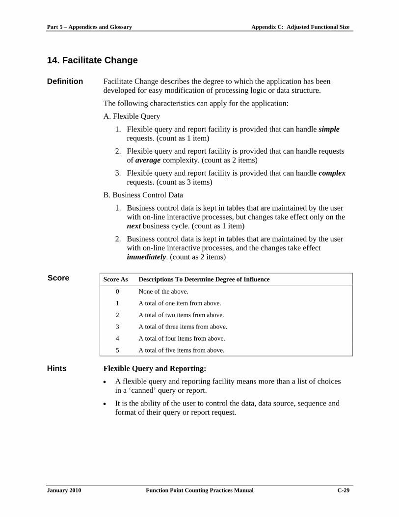
14. Facilitate Change Definition Facilitate Change describes the degree to which the application has been
developed for easy modification of processing logic or data structure.
The following characteristics can apply for the application:
A. Flexible Query
1. Flexible query and report facility is provided that can handle simple requests. (count as 1 item)
2. Flexible query and report facility is provided that can handle requests of average complexity. (count as 2 items)
3. Flexible query and report facility is provided that can handle complex requests. (count as 3 items)
B. Business Control Data
1. Business control data is kept in tables that are maintained by the user with on-line interactive processes, but changes take effect only on the next business cycle. (count as 1 item)
2. Business control data is kept in tables that are maintained by the user with on-line interactive processes, and the changes take effect immediately. (count as 2 items)
Score As Descriptions To Determine Degree of Influence
0 None of the above.
1 A total of one item from above.
2 A total of two items from above.
3 A total of three items from above.
4 A total of four items from above.
Score
5 A total of five items from above. Hints Flexible Query and Reporting:
• A flexible query and reporting facility means more than a list of choices in a ‘canned’ query or report.
• It is the ability of the user to control the data, data source, sequence and format of their query or report request.

Appendix C: Adjusted Functional Size Part 5 – Appendices and Glossary
C-30 Function Point Counting Practices Manual January 2010
Hints • It means freedom to design screen layout, horizontal and vertical sorting, data item display formats, selection criteria for both files and data items.
• It includes true user programming for inquiries and is sometimes referred to as ad hoc query or reporting.
• Using filters which control the amount of data viewed or printed in a fixed format is not considered to be a flexible query and report facility.
• Query and/or report writer capability is often provided by languages such as SQL or Focus or by some of the more dynamic ad hoc reporting tools (e.g., Crystal Reports).
Hint for
Rule A1 • Simple requests may include and/or logic applied to only one
internal logical file. Hint for
Rule A2 • Requests of average complexity may include and/or logic
applied to more than one internal logical file. Hint for
Rule A3 • Complex requests may include and/or logic combinations on
one or more internal logic files. Business Control Data:
• Business Control Data (Reference Data) is stored to support the business rules for the maintenance of the Business Data; e.g., in a payroll application it would be the data stored on the government tax rates for each wage scale and the date the tax rate became effective.
• See Part 2, Code Data for additional information. Typically Scoring is not platform dependent.

Part 5 – Appendices and Glossary Appendix C: Adjusted Functional Size
January 2010 Function Point Counting Practices Manual C-31
Value Adjustment Factor Calculation Table
The following table is provided to facilitate the calculation of the value adjustment factor.
General System Characteristics (GSCs) Degree of Influence (DI) 0 - 5
1. Data Communications
2. Distributed Data Processing
3. Performance
4. Heavily Used Configuration
5. Transaction Rate
6. On-line Data Entry
7. End-User Efficiency
8. On-line Update
9. Complex Processing
10. Reusability
11. Installation Ease
12. Operational Ease
13. Multiple Sites
14. Facilitate Change
Total Degree of Influence (TDI)
Value Adjustment Factor (VAF)
VAF = (TDI * 0.01) + 0.65

Appendix C: Adjusted Functional Size Part 5 – Appendices and Glossary
C-32 Function Point Counting Practices Manual January 2010
Adjusted Development Project Function Point (aDFP)
Application Functionality Application functionality consists of functions used after software installation
to satisfy the ongoing business needs of the user.
Conversion Functionality Conversion functionality consists of functions provided only at installation to
convert data and/or provide other user-specified conversion requirements, such as special conversion reports.
For example, if a Human Resources (HR) software application was in use and a new HR application is installed, the users may require that information about employees be converted and loaded into the new application. The user-specified conversion requirement is to transfer the current employee data into the new HR system.
Application Value Adjustment Factor The value adjustment factor is determined by using the 14 general system
characteristics to rate the application functional complexity.
Formula: Adjusted Development Project Functional Size (aDFP) Use the following formula to calculate the adjusted development project
functional size.
aDFP = DFP * VAF
Where:
aDFP is the adjusted development project functional size
DFP is the development project functional size (DFP = ADD + CFP; see Part 1)
VAF is the value adjustment factor
Note: After software installation, the application functional size is calculated using components of the development project functional size.

Part 5 – Appendices and Glossary Appendix C: Adjusted Functional Size
January 2010 Function Point Counting Practices Manual C-33
Example: Adjusted Development Project Functional Size (aDFP) This section shows an example of a development project. The project
includes both application and conversion functionality.
Note: The following is meant to be only an example and is not specifically related to other sections of this manual. All related functionality may not be included (e.g., there may be missing functions).
Application Functionality The following tables show the application functionality measured for a
development project. Data Functions
RETs
DETs
Functional Complexity
Internal Logical Files
• Job information 2 5 Low
• Suspended jobs 2 6 Low
• Report definition
• Employee information
1
1
4
6
Low
Low
External Interface Files
• Location information 1 6 Low
• Conversion information 1 2 Low
• Window help information 1 2 Low
• Field help information 1 5 Low

Appendix C: Adjusted Functional Size Part 5 – Appendices and Glossary
C-34 Function Point Counting Practices Manual January 2010
Transactional Functions
FTRs
DETs
Functional Complexity
External Inputs
Assignment report definition 1 5 Low
Add job information (screen input) 1 7 Low
Add job information (batch input) 2 6 Average
Correct suspended jobs 1 7 Low
Employee job assignment 3 7 High
EI with screen output –1 2 11 Average
EI with screen output –2 1 6 Low External Outputs
Jobs with employees report 4 5 Average
Employees by assignment duration report 3 7 Average
Performance review notification 3 4 Low
Weekly employees report 1 3 Low
Printed check 1 3 Low
Check transaction file 1 4 Low
External Inquiries
List of retrieved data 1 4 Low
Bargaining Unit 1 2 Low
Field level help 1 6 Low
Weekly membership report 1 3 Low
Daily check file 1 2 Low
Conversion Functionality The following table shows the conversion functionality for the development
project.
Transactional Function
FTRs
DETs
Functional Complexity
External Input
Employee migration 1 11 Low

Part 5 – Appendices and Glossary Appendix C: Adjusted Functional Size
January 2010 Function Point Counting Practices Manual C-35
Application Contribution to the Functional Size The following table shows the contribution to the unadjusted functional size.
Function Type
Functional Complexity
Complexity Totals
Function Type Totals
ILFs 4 Low X 7 = 28
0 Average X 10 = 0
0 High X 15 = 0
28
EIFs 4 Low X 5 = 20
0 Average X 7 = 0
0 High X 10 = 0
20
EIs 4 Low X 3 = 12
2 Average X 4 = 8
1 High X 6 = 6
26
EOs 4 Low X 4= 16
2 Average X 5 = 10
0 High X 7 = 0
26
EQs 5 Low X 3= 15
0 Average X 4 = 0
0 High X 6= 0
15
ADD 115

Appendix C: Adjusted Functional Size Part 5 – Appendices and Glossary
C-36 Function Point Counting Practices Manual January 2010
Conversion Contribution to the Functional Size The following table shows the contribution of the conversion functionality to
the functional size.
Function Type
Functional Complexity
Complexity Totals
Function Type Totals
EIs 1 Low X 3 = 3
0 Average X 4 = 0
0 High X 6 = 0
CFP 3
Final Calculation Using the complexity and contribution counts for this example, the adjusted
development project size is shown below. The value adjustment factor for this example is 1.05.
aDFP = (ADD + CFP) * VAF
aDFP = (115 + 3) * 1.05
aDFP = 123.9 or 124

Part 5 – Appendices and Glossary Appendix C: Adjusted Functional Size
January 2010 Function Point Counting Practices Manual C-37
Adjusted Enhancement Project Functional Size (aEFP)
The adjusted enhancement project functional size consists of three components:
• Application functionality included in the user requirements for the project
• Conversion functionality included in the user requirements for the project
• Application value adjustment factor
Enhancement Project GSC Considerations The optional 14 General System Characteristics (GSCs), defined in this appendix, should be reviewed for change. Small enhancements do not normally require such a review. Examples of changes that may indicate a need to review the GSCs include:
• Addition of on-line functions to a batch application
• Increased transaction volumes and/or degraded response times now requiring performance design and testing activities
• Additional usability features requested
• Addition of a Web interface to an existing on-line application
• Addition of a new communication protocol to an existing application
Application Functionality Application functionality consists of:
• Function points identified from the functionality that is added by the enhancements
• Function points measured because existing functionality is changed during the enhancement project
• Function points measured for functionality deleted during the enhancement project
Conversion Functionality The conversion functionality consists of function points delivered because of
any conversion functionality required by the user.

Appendix C: Adjusted Functional Size Part 5 – Appendices and Glossary
C-38 Function Point Counting Practices Manual January 2010
Value Adjustment Factor The two value adjustment factors are the:
• Application value adjustment factor before the enhancement project begins
• Application value adjustment factor after the enhancement project is complete
Formula: Adjusted Enhancement Project Functional Size (aEFP) Use the following formula to calculate the adjusted enhancement project
functional size.
Note: Data conversion requirements are included in this calculation.
aEFP = [(ADD + CHGA + CFP) * VAFA] + (DEL * VAFB)
Where:
aEFP is the adjusted enhancement project functional size
ADD is the size of the functions being added by the enhancement project
CHGA is the size of the functions being changed by the enhancement project – as they are / will be after implementation
CFP is the size of the conversion functionality
VAFA is the value adjustment factor of the application after the enhancement project is complete
DEL is the size of the functions being deleted by the enhancement project
VAFB is the value adjustment factor of the application before the enhancement project begins
Note: When an enhancement project is installed, the application functional size must be updated to reflect changes in the application's functionality.

Part 5 – Appendices and Glossary Appendix C: Adjusted Functional Size
January 2010 Function Point Counting Practices Manual C-39
Example: Adjusted Enhancement Project Functional Size (aEFP) This section shows an example for a sample enhancement project. The
requirements for the enhancement project include the following changes:
• The user no longer needs to add a job online, therefore, that functionality is to be or was removed.
• The user needs to receive an additional report about jobs that includes totals.
• Additional DETs are required to add jobs in batch and correct suspended transactions. A reference to government security clearances (an additional FTR) is also added for the add job transaction.
Application Functionality The following paragraphs explain the application functionality counted for
the example enhancement project. Functionality is described as added, changed, or deleted.
Added Functionality The following table shows the functional complexity for the added
functionality that is measured when the project was completed.
Note: Providing a new report was an additional external output.
Transactional Functions
FTRs
DETs
Functional Complexity
External Output
Job report 1 15 Low
Changed Functionality The following table shows the functional complexity for the changed
functionality, as the functions will exist after the enhancement project is completed.
Note: The complexity for adding a job was increased because of the additional file type referenced. The complexity for correcting suspended transactions remained low.

Appendix C: Adjusted Functional Size Part 5 – Appendices and Glossary
C-40 Function Point Counting Practices Manual January 2010
After
Transactional Functions
FTRs
DETs
Functional Complexity
External Input Add job information (batch input) 3 8 High
Correct suspended transaction 1 8 Low
Before
Transactional Functions
FTRs
DETs
Functional Complexity
External Input Add job information (batch input) 2 6 Average
Correct suspended transaction 1 7 Low
Deleted Functionality The following table shows the functional complexity for deleted functionality
identified at the end of the project.
Transactional Functions
FTRs
DETs
Functional Complexity
External Inputs Add job information (screen input) 1 7 Low

Part 5 – Appendices and Glossary Appendix C: Adjusted Functional Size
January 2010 Function Point Counting Practices Manual C-41
Application Contribution to the Functional Size The following paragraphs explain the application functionality contribution to
the total unadjusted functional size.
Added Functionality The following table shows the contribution to the functional size for the
added functionality identified at the end of the project.
Function Type
Functional Complexity
Complexity Totals
Function Type Totals
EOs 1 Low X 4= 4
0 Average X 5 = 0
0 High X 7 = 0
ADD 4
Changed Functionality The following table shows the contribution to the functional size for the
changed functionality as it will exist after the enhancement project is complete.
After
Function Type
Functional Complexity
Complexity Totals
Function Type Totals
EIs 1 Low X 3 = 3
0 Average X 4 = 0
1 High X 6 = 6
CHGA 9
Before
Function Type
Functional Complexity
Complexity Totals
Function Type Totals
EIs 1 Low X 3 = 3
1 Average X 4 = 4
0 High X 6 = 0
CHGB 7

Appendix C: Adjusted Functional Size Part 5 – Appendices and Glossary
C-42 Function Point Counting Practices Manual January 2010
Deleted Functionality The following table shows the contribution to the functional size for the
deleted functionality.
Function Type
Functional Complexity
Complexity Totals
Function Type Totals
EIs 1 Low X 3 = 3
0 Average X 4 = 0
0 High X 6 = 0
DEL 3
Final Calculation The application value adjustment factor was 1.05 before the project began.
The value adjustment factor remained the same after the project was completed.
Using the complexity and contribution counts for this example, the adjusted enhancement project functional size is shown below.
aEFP = [(ADD + CHGA + CFP) * VAFA] + (DEL* VAFB)
aEFP = [(4 + 9 + 0) * 1.05] + (3 * 1.05)
aEFP = 16.8 or 17

Part 5 – Appendices and Glossary Appendix C: Adjusted Functional Size
January 2010 Function Point Counting Practices Manual C-43
Adjusted Application Functional Size (aAFP)
This section provides the formulas to calculate the adjusted application functional size. There are two variations of this formula:
• Formula to establish the initial adjusted functional size for an application
• Formula to re-establish the adjusted functional size for an application after an enhancement project has changed the application functionality
Formula: Initial Adjusted Application Functional Size (aAFP) Use the formula in this section to establish the initial adjusted functional size
for an application. Initially, the user is receiving new functionality. There are no changes to the existing functionality or deletions of obsolete or unneeded functionality. The adjusted application functional size does not include conversion requirements.
aAFP = ADD * VAF
Where:
aAFP is the initial adjusted application functional size
ADD is the size of the functions by the development project to be delivered to the user or the functionality that exists whenever the application is measured.
VAF is the value adjustment factor of the application.

Appendix C: Adjusted Functional Size Part 5 – Appendices and Glossary
C-44 Function Point Counting Practices Manual January 2010
Formula: Adjusted Application Functional Size After Enhancement Projects (aAFPA) When an enhancement project is installed, the existing application functional
size must be updated to reflect modifications to the application. The functionality for the application can be altered in one or more ways:
• Added (new) functionality increases the size of the application
• Changed functionality increases, decreases, or has no effect on the size of the application
• Deleted functionality decreases the application size
• Changes to the value adjustment factor increase or decrease the application size
Note: Because conversion functionality does not affect the adjusted application functional size, any conversion functionality associated with an enhancement project is omitted entirely from the adjusted application functional size calculation.
Use the following formula to calculate the adjusted application functional size after an enhancement project:
aAFPA = [(AFPB + ADD + CHGA) - (CHGB + DEL)] * VAFA
Where:
aAFPA is the adjusted application functional size after the enhancement project
AFPB is the application functional size before the enhancement project begins
ADD is the size of the functions being added by the enhancement project.
CHGA is the size of the functions being changed by the enhancement project – as they are / will be after implementation
CHGB is the size of the functions being changed by the enhancement project – as they are / were before the project commenced
DEL is the size of the functions being deleted by the enhancement project.
VAFA is the value adjustment factor of the application after the enhancement project is complete.

Part 5 – Appendices and Glossary Appendix C: Adjusted Functional Size
January 2010 Function Point Counting Practices Manual C-45
Note: If the AFPB is unavailable, it can be calculated using the formula AFPB = aAFPB/VAFB; where aAFPB is the adjusted application functional size before the enhancement project and VAFB is the value adjustment factor of the application before the enhancement project.
Example: Application Count This section shows an example for the initial adjusted functional size and the
adjusted functional size that reflects an enhancement project. Numbers for these functional size measurements are from the application example earlier in this appendix.
Initial Adjusted Application Functional Size (aAFP) The initial adjusted application functional size is shown below. The value
adjustment factor is 1.05.
aAFP = ADD * VAF
aAFP = 115 * 1.05
aAFP = 120.75 or 121
Note: Only the size of the application functionality installed for the user is included in the initial size.
Adjusted Application Functional Size After (aAFPA) The adjusted application project functional size to reflect enhancements is
shown below. The value adjustment factor is 1.05.
aAFPA = [(AFPB + ADD + CHGA) - (CHGB + DEL)]* VAFA
aAFPA = [(115 + 4 + 9) - (7 + 3)]* 1.05
aAFPA = 123.9 or 124

Appendix C: Adjusted Functional Size Part 5 – Appendices and Glossary
C-46 Function Point Counting Practices Manual January 2010
This page intentionally left blank.

Part 5 IFPUG Glossary
January 2010 Function Point Counting Practices Manual G-1
IFPUG Glossary This is a comprehensive glossary of terms used across IFPUG publications.
Adaptive maintenance. The modification of a
software product, performed after delivery, to keep a software product usable in a changed or changing environment. Adaptive maintenance provides enhancements necessary to accommodate changes in the environment in which a software product must operate. These changes are those that must be made to keep pace with the changing environment. For example, the operating system might be upgraded and some changes may be made to accommodate the new operating system. (ISO/IEC 14764:2006)
Adjusted functional size. The adjusted functional size is the result of the unadjusted functional size multiplied by the value adjustment factor. The adjusted functional size is calculated using a specific formula for development project, enhancement project, and application, which is illustrated in Appendix C.
Adjusted application functional size (aAFP). See Appendix C for the formula.
Adjusted application functional size after enhancement projects (aAFPA). See Appendix C for the formula.
Adjusted development project functional size (aDFP). See Appendix C for the formula.
Adjusted enhancement project functional size (aEFP). See Appendix C for the formula.
Albrecht 1984. Original document of the function point concept, written by Allan J. Albrecht in November 1984. Also known as "313" from its document number.
Application. An application is a cohesive collection of automated procedures and data supporting a business objective; it consists of one or more components, modules, or subsystems.
Application area. A general term for a grouping of applications that handle a specific business area. It corresponds to an administrative level for management purposes.
Application area level. The management level responsible for managing maintenance activities as well as new development or major enhancement projects for one or more applications.
Application boundary. See Boundary.
Application functional size. An application’s functional size is a measure of the functionality that an application provides to the user, determined by the application function point count by the activity of applying the IFPUG Functional Size Measurement (FSM) Method. See Part 1, Section 5.8 for the formula.
Application function point count. Activity of applying the IFPUG Functional Size Measurement (FSM) Method to measure the functional size of an application.
Application manager. A person responsible for managing projects and support activities for one or more application areas.
Arranging. The activity of sequencing attributes in a transactional function.
Asset. (1) A capital asset of the enterprise. (2) An advantage or resource.

IFPUG Glossary Part 5 – Appendices and Glossary
G-2 Function Point Counting Practices Manual January 2010
Associative entity type. An entity type that contains attributes which further describe a many-to-many relationship between two other entity types.
Attribute. See Project/application attribute and Data attribute.
Attributive entity type. An entity type that further describes one or more characteristics of another entity type.
Base functional component (BFC) . Elementary unit of Functional User Requirements defined by and used by an FSM Method for measurement purposes. (ISO/IEC 14143-1:2007) ILFs, EIFs, EIs, EOs, EQs are types of BFCs.
Baseline function point count. See Application function point count.
Boundary. The boundary is a conceptual interface between the software under study and its users.
Boundary of application. See Boundary.
Budget. A planned sequence of expenditures over time with monetary costs assigned to specific tasks or jobs. Often used also to refer to work effort as well as, or instead of, money.
Business data. May also be referred to as Core User Data or Business Objects. This type of data reflects the information needed to be stored and retrieved by the functional area addressed by the application. Business Data usually represents a significant percentage of the entities identified.
Capital expenditure. A form of spending in which an enterprise trades money (capital) for acquisition of tangible objects such as furniture, computers, and the like.
Code data. The user does not always directly specify Code Data, sometimes referred to as List Data or Translation Data. In other cases it is identified by the developer in response to one or more technical requirements of the user. Code Data provides a list of valid values that a descriptive attribute may have. Typically the attributes of the Code Data are Code, Description and/or other ‘standard’ attributes describing the code; e.g., standard abbreviation, effective date, termination date, audit trail data, etc.
Copy. (1) To read data from a source, leaving the source data unchanged, and to write the same data elsewhere in a physical form that may differ from that of the source. For example, to copy data from a magnetic disk onto a magnetic tape. (2) The result of a copy process as in above. For example, a copy of a data file. (IEEE)
Complex processing GSC. One of the 14 general system characteristics describing the degree to which processing logic influences the development of the application.
Consistent state. The point at which processing has been fully executed; the functional user requirement has been satisfied and there is nothing more to be done.
Contribution. The function type's (ILF, EIF, EI, EO, EQ) contribution to the functional size.
Control information. Control Information is data that influences an elementary process by specifying what, when or how data is to be processed.
Conversion functionality. Transactional or data functions provided to convert data and/or provide other user specified conversion requirements.
Corporate executive level. The management level responsible for the enterprise, including the Board of Directors.
Corrective maintenance. The reactive modification of a software product performed after delivery to correct discovered problems. The modification repairs the software product to satisfy requirements. (ISO/IEC 14764:2006)
Counting Practices Committee (CPC). The working committee that maintains the IFPUG Counting Practices Manual.
Counting scope. The counting scope defines the set of Functional User Requirements to be included in the function point count.
Data attribute. A characteristic of an entity. Data attributes are generally analogous to data element types (DETs). Also known as field.
Data communications GSC. One of the 14 general system characteristics describing the degree to which the application communicates directly with the processor.
Data element type (DET). A data element type is a unique, user recognizable, non-repeated attribute.

Part 5 – Appendices and Glossary IFPUG Glossary
January 2010 Function Point Counting Practices Manual G-3
Data entity. See Entity.
Data function. A data function represents functionality provided to the user to meet internal and external data storage requirements. A data function is either an internal logical file or an external interface file.
Defect. A problem which, if not corrected, could cause an application to either fail or to produce incorrect results. The absence of functionality that was specified or required is also considered a defect.
Defect removal. See Repair.
Degree of influence (DI). A numerical indicator of the amount of impact of each of the 14 general system characteristics, ranging from zero to five. These indicators are used to compute the value adjustment factor.
Delivery rate. The productivity measure for creating or enhancing an application. It is expressed by the Project Function Points divided by the Work Effort for the development or enhancement project.
Derived data. Data created as a result of processing that involves steps, other than or in addition to, direct retrieval and validation of information from data functions.
Development project. A development project is a project to develop and deliver the first release of a software application.
Development project functional size. The development project functional size is a measure of the functionality provided to the users with the first release of the software, as measured by the development project function point count by the activity of applying the IFPUG Functional Size Measurement (FSM) Method. See Part 1, Section 5.8 for the formula.
Development project function point count. The activity of applying the IFPUG Functional Size Measurement (FSM) Method to measure the functional size of a development project.
Distributed data processing GSC. One of the 14 general system characteristics describing the degree to which the application transfers data among physical components of the application.
Effectiveness. Producing the intended or desired result.
Efficiency. Producing a result with a minimum of extraneous or redundant effort.
Elementary process (EP). An elementary process is the smallest unit of activity that is meaningful to the user.
End-user efficiency GSC. One of the 14 general system characteristics describing the degree of consideration for human factors and ease of use for the user of the application measured.
Enhancement project. An enhancement project is a project to develop and deliver adaptive maintenance.
Enhancement project functional size. The enhancement project functional size is a measure of the functionality added, changed or deleted at the completion of an enhancement project, as measured by the enhancement project function point count by the activity of applying the IFPUG Functional Size Measurement (FSM) Method. See Part 1, Section 5.8 for the formula.
Enhancement project function point count. The activity of applying the IFPUG Functional Size Measurement (FSM) Method to measure of the functional size of an enhancement project.
Entity (or entity type). A fundamental thing of relevance to the user, about which a collection of facts is kept. An association between entities that contains attributes is itself an entity.
Entity dependent. An entity that is not meaningful or is not significant to the business, in and of itself without the presence of other entities such that
• an occurrence of entity X must be linked to an occurrence of entity Y
• the deletion of an occurrence of entity Y results in the deletion of all related occurrences of entity X.
Entity independent. An entity that is meaningful or significant to the business, in and of itself without the presence of other entities.
Entity subtype. A subdivision of entity type. A subtype inherits all the attributes and relationships of its parent entity type, and may have additional, unique attributes and relationships.
External input (EI). An external input (EI) is an elementary process that processes data or control information sent from outside the boundary. The primary intent of an EI is to maintain one or more ILFs and/or to alter the behavior of the system.

IFPUG Glossary Part 5 – Appendices and Glossary
G-4 Function Point Counting Practices Manual January 2010
External inquiry (EQ). An external inquiry (EQ) is an elementary process that sends data or control information outside the boundary. The primary intent of an external inquiry is to present information to a user through the retrieval of data or control information. The processing logic contains no mathematical formula or calculation, and creates no derived data. No ILF is maintained during the processing, nor is the behavior of the system altered.
External interface file (EIF). An external interface file (EIF) is a user recognizable group of logically related data or control information, which is referenced by the application being measured, but which is maintained within the boundary of another application. The primary intent of an EIF is to hold data referenced through one or more elementary processes within the boundary of the application measured. This means an EIF counted for an application must be in an ILF in another application.
External output (EO). An external output (EO) is an elementary process that sends data or control information outside the application’s boundary and includes additional processing beyond that of an external inquiry. The primary intent of an external output is to present information to a user through processing logic other than or in addition to the retrieval of data or control information. The processing logic must contain at least one mathematical formula or calculation, create derived data, maintain one or more ILFs, and/or alter the behavior of the system.
Facilitate change GSC. One of the 14 general system characteristics describing the degree to which the application has been developed for easy modification of processing logic or data structure.
Field. See Data attribute.
File. For data functions, a logically related group of data, not the physical implementation of those groups of data.
File system. Is composed of records and data attributes.
File type referenced (FTR). A file type referenced is a data function read and/or maintained by a transactional function.
First normal form. Result of a normalization process that transforms groups of data so they have a unique identifier, one or more attributes, and no repeating attributes.
Foreign key. Data in an ILF or EIF that exists because the user requires a relationship with another ILF or EIF.
Function. The features or capabilities of an application as seen by the user.
Functional complexity. The specific complexity rating assigned to a function using the rules as defined within this International Standard.
Functional size. Size of the software derived by quantifying the functional user requirements. (ISO 14143-1:2007)
Functional user requirements. A sub-set of the user requirements specifying what the software shall do in terms of tasks and services. (ISO 14143-1:2007)
Functionality. See Function.
Function point (FP). The unit of measure for functional size as defined within the IFPUG Functional Size Measurement (FSM) Method.
Function point analysis. The method for measuring functional size as defined within the IFPUG Functional Size Measurement (FSM) Method.
Function point count. The activity of applying the rules within the IFPUG Functional Size Measurement (FSM) Method to measure the functional size of an application or project. NOTE: There are three types of function point counts: application, development project and enhancement project.
Function type. The five base functional components identified in the IFPUG Functional Size Measurement (FSM) Method. NOTE: The five function types are: External Input, External Output, External Inquiry, Internal Logical File and External Interface File. Also known as Base functional component.
General system characteristics (GSCs). The general system characteristics are a set of 14 questions that evaluate the overall complexity of the application.
Heavily used configuration GSC. One of the 14 general system characteristics describing the degree to which computer resource restrictions influenced the development of the application.
IBM CIS & A Guideline 313. See Albrecht 1984.

Part 5 – Appendices and Glossary IFPUG Glossary
January 2010 Function Point Counting Practices Manual G-5
IFPUG. The International Function Point Users Group is a membership governed, non-profit organization committed to promoting and supporting function point analysis and other software measurement techniques.
Image. An exact replication of another object, file, or table that is usually created through a utility.
Installation ease GSC. One of the 14 general system characteristics describing the degree to which conversion from previous environments influenced the development of the application.
Installed function point count. See Application function point count.
Internal logical file (ILF). An internal logical file (ILF) is a user recognizable group of logically related data or control information maintained within the boundary of the application being measured. The primary intent of an ILF is to hold data maintained through one or more elementary processes of the application being measured.
Load. To copy computer instructions or data from external storage to internal storage. (IEEE)
Logical file. See Data function.
Maintain. The term maintain refers to the ability to add, change or delete data through an elementary process.
Maintenance. The effort to keep an application performing according to its specifications, generally without changing its functionality (or functional size). Maintenance includes repair, minor enhancement, conversion, user support and preventive maintenance activities. Activities include defect removal (see repair), hardware or software upgrades (see conversion), optimization or quality improvement (see preventive maintenance), and user support.
Maintenance (support) rate. The productivity measure for maintaining an application. It is expressed as the Work Effort by category of maintenance divided by 1000 Application Function Points in a period of time.
Mandatory subgroup. One of the two types of subgroups for record element types (RETs). Mandatory subgroups mean the user must use one of the subgroups during an elementary process that creates an instance of the data.
Meaningful. Is user recognizable and satisfies a Functional User Requirement.
Measure. As a noun, a number that assigns relative value. Some examples may include volume, height, function points, or work effort. As a verb, to ascertain or appraise by comparing to a standard.
Measurement. Assigning relative value. Usually, in the improvement process, measures gained from this activity are combined to form metrics.
Media/Medium. A channel of communication or information, for example, a report issued on paper or in microfiche.
Merge. Multiple files with the same data elements consolidated into a single file. (IEEE)
Metric. There is no single universal definition of a metric. In the context of this document, a metric is a combination of two or more measures or attributes. Examples include (1) defect density (defects per function point) and (2) delivery rates (function points per hour).
Multiple sites GSC. One of the 14 general system characteristics describing the degree to which the application has been developed for different hardware and software environments.
NESMA. The Netherlands Software Metrics Association (www.nesma.org). A membership governed, non-profit organization in the Netherlands, committed to promoting and supporting function point analysis and other software measurement methods.
Normalization. The process by which any data structure can be transformed by a database designer into a set of normalized relations that have no repeating groups.
Online data entry GSC. One of the 14 general system characteristics describing the degree to which data is entered or retrieved through interactive transactions.
Online update GSC. One of the 14 general system characteristics describing the degree to which internal logical files are updated online.
Operational ease GSC. One of the 14 general system characteristics describing the degree to which the application attends to operational aspects, such as, start-up, back-up, and recovery processes.
Optional subgroup. Optional subgroups are those that the user has the option of using one or none of the subgroups during an elementary process that adds or creates an instance or the data.

IFPUG Glossary Part 5 – Appendices and Glossary
G-6 Function Point Counting Practices Manual January 2010
Organization level. The management level or levels responsible for managing one or more data processing or information systems organizations.
Perfective maintenance. Modification of a software product after delivery to detect and correct latent faults in the software product before they are manifested as failures. Perfective maintenance provides enhancements for users, improvement of program documentation, and recoding to improve software performance, maintainability, or other software attributes. Contrast with: adaptive maintenance; corrective maintenance. (ISO/IEC 14764:2006)
Performance GSC. One of the 14 general system characteristics describing the degree to which response time and throughput performance considerations influenced the application development.
Preventive maintenance. Changes to hardware or software performed to prevent future defects or failures. For example, restructuring programs or data to improve maintainability or to prevent defects.
Primary intent. Intent that is first in importance.
Process measures. Information captured about the development process.
Processing logic. Any of the requirements specifically requested by the user to complete an elementary process such as validations, algorithms or calculations and reading or maintaining a data function.
Product measures. Information captured about the developed software application.
Productivity. The ratio of work product to work effort. See also Delivery rate.
Project. A collection of work tasks with a time frame and a work product to be delivered.
Project/application attribute. Characteristics of a project or an application that may have a significant impact on productivity. Examples include hardware platform, personnel experience, tools, and methodology. The project/application attribute is used to categorize project data during analysis.
Project leader. A person who manages or leads projects. May be a synonym for Project Manager.
Project level. The management level responsible for managing individual new development or major enhancement projects.
Project manager. A person who manages one or more projects or groups of projects.
Purpose of the count. The reason for performing the function point count.
Quality. Quality includes: conformity to user expectations, conformity to user requirements, customer satisfaction, reliability, level of defects present. Context and policy will decide the best definition for a given situation.
Quality requirements. Any requirements relating to software quality as defined in ISO/IEC 9126:1991.
Ratio. In the context of this document, ratio is defined as the result of dividing one measured quantity by another.
Record. A group of related items that is treated as a unit.
Record element type (RET). A record element type (RET) is a user recognizable sub-group of data element types within a data function.
RECUP. Acronym for Repair/Enhancement/ Conversion/User support/Prevention. See also Maintenance (support) rate.
Reference data. This type of data is stored to support the business rules for the maintenance of the Business Data; e.g., in a payroll application it would be the data stored on the government tax rates for each wage scale and the date the tax rate became effective. Reference Data usually represents a small percentage of entities identified.
Refresh. The process of recreating a set of data to make it current with its source.
Relationship. An association of interest between two entities. A relationship does not have attributes and does not count as a RET when counting function points.
Release. A delivered version of an application which may include all or part of an application.
Repair. The correction of defects that have resulted from errors in external design, internal design, or code. Examples are missing functions that do not result in application failure (external design error) or errors resulting in a stop-run situation (code error).

Part 5 – Appendices and Glossary IFPUG Glossary
January 2010 Function Point Counting Practices Manual G-7
Reusability GSC. One of the 14 general system characteristics describing the degree to which the application and the code in the application have been specifically designed, developed, and supported to be usable in other applications.
Scope creep/gallop. Additional functionality that was not specified in the original requirements, but is identified as the scope is being clarified and the functions defined.
Second normal form. Result of a normalization process that transforms groups of data so that each non-key attribute depends on the key attribute(s) of the group of data and all parts of the key attribute(s).
Self-contained. No prior or subsequent processing steps are needed to initiate or complete the functional user requirement(s).
Software Engineering Institute (SEI) Maturity. The ability of an organization to achieve a controlled and measured process as the foundation for continued improvement (Humphrey). The level of experience of an organization or project with a particular tool, resource, technique, or methodology.
Sorting. The activity of sequencing of rows or records in a transactional function.
Subtypes. See Entity subtypes.
Support. See Maintenance.
System. See Application.
Technical attribute. Non-functional attribute that is a result of a design or implementation consideration.
Technical requirements. Requirements are related to the technology and environment, for the development, maintenance, support and execution of the software.
Third normal form. Result of a normalization process that transforms groups of data so that each non-key attribute does not depend on any other non-key attribute.
Total degree of influence (TDI). The sum of the degrees of influence for the fourteen GSCs.
Transactional function. A transactional function is an elementary process that provides functionality to the user to process data. A transactional function is an external input, external output, or external inquiry.
Transaction. See Transactional function.
Transaction rate GSC. One of the 14 general system characteristics describing the degree to which the rate of business transactions influenced the development of the application.
Trend. A time analysis showing repeated occurrences of a particular measure or metric.
Unadjusted functional size. See Functional size.
Unadjusted function point count (UFP). See Function point count.
User. A user is any person or thing that communicates or interacts with the software at any time.
User recognizable. The term user recognizable refers to requirements for processes and/or data that are agreed upon, and understood by, both the user(s) and software developer(s).
User view. A user view is the Functional User Requirements as perceived by the user.
Value adjustment factor (VAF). The factor that indicates the general functionality provided to the user of the application. The VAF is calculated based on an assessment of the 14 general system characteristics (GSCs) for an application.
Work effort. Labor resources required for the production of a specified output. Here referring to the effort required to develop or maintain an application. Labor resources are usually expressed as work hours.
Work product. The product that is created by information systems work, here the result of a software development effort.
313. See Albrecht 1984.

IFPUG Glossary Part 5 – Appendices and Glossary
G-8 Function Point Counting Practices Manual January 2010
This page intentionally left blank.