Embed Size (px)
Citation preview

VOLUME V – PART 5
PRESTRESSED CONCRETE SLAB
STANDARDS
VIRGINIA DEPARTMENT OF
TRANSPORTATION

VirginiaDOT.org WE KEEP VIRGINIA MOVING
COMMONWEALTH of VIRGINIA
DEPARTMENT OF TRANSPORTATION 1401 EAST BROAD STREET
RICHMOND, 23219-2000
Gregory A. Whirley COMMISSIONER
August 30, 2012 SUBJECT: Manual of the Structure and Bridge Division Volume V – Part 5 Prestressed Concrete Slab Standards MEMORANDUM TO: Holders of Volume V – Part 5: Prestressed Concrete Slab Standards The revision is intended to clarify modifications to standards. Design waivers/exceptions are required when changes to the standards are made. VOIDED: None NEW ISSUES:
None REVISIONS: File Number Description of change(s) TOC-1 Revised date of sheet. INSTR-1 Revised modification policy.

Page 2 August 30, 2012 RETAIN THIS MEMO IN FRONT OF INDEX TO VOLUME V – PART 5 /original signed/ Julius F. J. Völgyi, Jr., P.E. Assistant State Structure and Bridge Engineer For: Kendal R. Walus, P.E. State Structure and Bridge Engineer

VirginiaDOT.org WE KEEP VIRGINIA MOVING
COMMONWEALTH of VIRGINIA
DEPARTMENT OF TRANSPORTATION 1401 EAST BROAD STREET
RICHMOND, 23219-2000
Gregory A. Whirley COMMISSIONER
August 7, 2012 SUBJECT: Manual of the Structure and Bridge Division Volume V – Part 5 Prestressed Concrete Slab Standards MEMORANDUM TO: Holders of Volume V – Part 5: Prestressed Concrete Slab Standards NOTES: Standards are revised for corrosion resistant reinforcing (CRR) steel designations (Class I, II or III) that will be effective with the March 2013 ad date. For projects going to ad prior to that date, CRR steels that are designated on the standards must be changed to one or more of the following: corrosion resistant reinforcing steel – low carbon chromium corrosion resistant reinforcing steel – stainless clad corrosion resistant reinforcing steel – solid stainless For more information on CRR, see the current IIM-S&B-81.
VOIDED: None

Page 2 August 7, 2012 NEW ISSUES:
File Number Description of change(s) PSS-1B-1, PSS-1B-2 and New Standard and Notes to Designer for voided PSS-1B-3 slabs with concrete slabs. PSSCELLS-5 and Added new cells: EP15C, EP18C, EP21C, EP15D, EP18D and PSSCELLS-6 EP21D for exterior prestressed concrete slabs with concrete slabs. REVISIONS: File Number Description of change(s) TOC-1 Revised date of applicable sheets. PSS-1A-1 Renamed standard “PSS-1” to “PSS-1A.” PSS-1A-2 Added “Asphalt Overlay” to title and renamed standard “PSS-1” to
“PSS-1A.” PSS-2-1 Notes: Added “Class …” to Corrosion Resistant Reinforcing
Steel. PSS-2-3 Under Notes, replaced “type” with “Class I, II or III.” PSS-3F-1 Notes: Added “Class ….” to Corrosion Resistant Reinforcing
Steel. PSS-3F-2 Notes: Replaced “type” with “Class I, II or III.” CELLINDEX-1 Revised date of applicable cells and added two pages of cells. PSSCELLS-1 and Description: Revised “PSS-1” to “PSS-1A and PSS-1B.” PSSCELLS-2

Page 3 August 7, 2012 REVISIONS (continued): File Number Description of change(s) PSSCELLS-3 and Description: Revised “PSS-1” to “PSS-1A.” PSSCELLS-4 PSSCELLS-7 thru Moved contents to next page. PSSCELLS-10 RETAIN THIS MEMO IN FRONT OF INDEX TO VOLUME V – PART 5 /original signed/ Julius F. J. Völgyi, Jr., P.E. Assistant State Structure and Bridge Engineer For: Kendal R. Walus, P.E. State Structure and Bridge Engineer

VirginiaDOT.org WE KEEP VIRGINIA MOVING
COMMONWEALTH of VIRGINIA
DEPARTMENT OF TRANSPORTATION 1401 EAST BROAD STREET
RICHMOND, 23219-2000
Gregory A. Whirley COMMISSIONER
May 29, 2012 SUBJECT: Manual of the Structure and Bridge Division Volume V – Part 5 Prestressed Concrete Slab Standards MEMORANDUM TO: Holders of Volume V – Part 5: Prestressed Concrete Slab Standards VOIDED: File Number Description of change(s) None NEW ISSUES: File Number Description of change(s)
None

Page 2 May 29, 2012 REVISIONS: File Number Description of change(s) TOC-1 Revised date of applicable sheets. PSS-1 Revised Detail A, the longitudinal shear key, a Drip Detail and
added requirement for 5,000 lb. min. strength for grout in notes. PSS-3F Revised the distance to bolts in Section E-E. Added 2 ft. dimension
for concrete base in Section F-F. Revised slab extension from 2 ft. -3in. to 1ft.-2 in. in Abutment Elevation View.
CELLINDEX-1 Revised date of applicable cells. PSSCELLS-1 Clarified the location of the transverse tendon in Cells VS15A,
VS18A and VS21A. PSSCELLS-2 Clarified the location of the transverse tendon in Cells VS15B,
VS18B and VS21B. PSSCELLS-3 Revised the location of the transverse tendon in Cells EP15A,
EP18A and EP21A. PSSCELLS-4 Revised the location of the transverse tendon in Cells EP15B,
EP18B and EP21B. RETAIN THIS MEMO IN FRONT OF INDEX TO VOLUME V – PART 5 /original signed/ Julius F. J. Völgyi, Jr., P.E. Assistant State Structure and Bridge Engineer For: Kendal R. Walus, P.E. State Structure and Bridge Engineer

VirginiaDOT.org WE KEEP VIRGINIA MOVING
COMMONWEALTH of VIRGINIA
DEPARTMENT OF TRANSPORTATION 1401 EAST BROAD STREET
RICHMOND, 23219-2000
Gregory A. Whirley Acting COMMISSIONER
June 14, 2010 SUBJECT: Manual of the Structure and Bridge Division Volume V – Part 5 Prestressed Concrete Slab Standards MEMORANDUM TO: Holders of Volume V – Part 5: Prestressed Concrete Slab Standards VOIDED: File Number Description of change(s) None NEW ISSUES: File Number Description of change(s) None REVISIONS: Note: For all standards, the block with FHWA Region 3 and block in the upper right corner for Special Provisions/Copied Notes has been deleted. The copyright date has been changed to 2010.

Page 2 June 14, 2010 RETAIN THIS MEMO IN FRONT OF INDEX TO VOLUME V – PART 5 /original signed/ Julius F. J. Völgyi, Jr., P.E. Assistant State Structure and Bridge Engineer For: Kendal R. Walus, P.E. State Structure and Bridge Engineer

VirginiaDOT.org WE KEEP VIRGINIA MOVING
COMMONWEALTH of VIRGINIA
DEPARTMENT OF TRANSPORTATION 1401 EAST BROAD STREET
RICHMOND, 23219-2000
David S. Ekern, P.E. COMMISSIONER
January 7, 2010 SUBJECT: Manual of the Structure and Bridge Division Volume V – Part 5 Prestressed Concrete Slab Standards MEMORANDUM TO: Holders of Volume V – Part 5: Prestressed Concrete Slab Standards VOIDED STANDARDS: None NEW ISSUES: None REVISIONS:
File Number Description of changes(s) TOC-1 PSS-2
PSS-2-3 PSS-3F PSS-3F-2
Revised date. Revised the reinforcing steel note to call for corrosion resistantreinforcing steel (CRR). Added instructions for the designer to specify the type of CRR. Revised the reinforcing steel note to call for corrosion resistant reinforcing steel (CRR). Added instructions for the designer to specify the type of CRR.

Page 2 January 7, 2010 RETAIN THIS MEMO IN FRONT OF INDEX TO VOLUME V – PART 5 /original signed/ Julius F. J. Völgyi, Jr., P.E. Assistant State Structure and Bridge Engineer For: Kendal R. Walus, P.E. State Structure and Bridge Engineer
VirginiaDOT.org WE KEEP VIRGINIA MOVING
COMMONWEALTH of VIRGINIA
DEPARTMENT OF TRANSPORTATION 1401 EAST BROAD STREET
RICHMOND, 23219-2000 David S. Ekern, P.E.
COMMISSIONER
May 29, 2009 SUBJECT: Manual of the Structure and Bridge Division Volume V – Part 5 Prestressed Concrete Slab Standards MEMORANDUM TO: Holders of Volume V – Part 5: Prestressed Concrete Slab Standards NOTE: Effective with the December Advertisement, Standards shall be sealed and signed in accordance with Volume V – Part 2, File No. 01.16.1 thru 01.16.7. VOIDED STANDARDS: None NEW ISSUES: None REVISIONS: File Number Description of changes(s) All standard sheets CELL-INDEX-1 PSSCELLS-5 thru -8
All standard sheets have been revised to reflect the border forsealing and signing of plans. Updated release date of cells. Minor drafting corrections to cells ERD2L, ERD2R, ERD3L, ERD3R, RPINL, and RPINR.
Page 2 May 29, 2009 RETAIN THIS MEMO IN FRONT OF INDEX TO VOLUME V – PART 5. /original signed/ Julius F. J. Völgyi, Jr., P.E. Assistant State Structure and Bridge Engineer For: Kendal R. Walus, P.E. State Structure and Bridge Engineer

VirginiaDOT.org WE KEEP VIRGINIA MOVING
COMMONWEALTH of VIRGINIA
DEPARTMENT OF TRANSPORTATION 1401 EAST BROAD STREET
RICHMOND, 23219-2000 David S. Ekern, P.E.
COMMISSIONER
July 11, 2008 SUBJECT: Manual of the Structure and Bridge Division Volume V – Part 5 Prestressed Concrete Slab Standards MEMORANDUM TO: Holders of Volume V – Part 5: Prestressed Concrete Slab Standards All of the standard sheets in this series have been revised .Two blocks for the P.E. stamp have been added to the lower left hand corner and the copyright date has been changed to 2008. Some details have been rearranged to provide space for the P.E. stamps. NOTE: Standard sheets are not required to be sealed and signed at this time. VOIDED STANDARDS: None NEW ISSUES: File Number Description INSTR-2 and 3 Added instructions for external users for accessing MicroStation
(.dgn) files and cell library (pss.cel) and for printing manual. REVISIONS: File Number Description of change(s) TOC-1 Added -DGN link to each standard file. Table of contents updated.
Added –CEL link for cell library. INSTR-1 Falcon location is changed.

Page 2 July 11, 2008 RETAIN THIS MEMO IN FRONT OF INDEX TO VOLUME V – PART 5. /original signed/ Julius F. J. Völgyi, Jr., P.E. Assistant State Structure and Bridge Engineer For: Kendal R. Walus, P.E. State Structure and Bridge Engineer

VirginiaDOT.org WE KEEP VIRGINIA MOVING
COMMONWEALTH of VIRGINIA
DEPARTMENT OF TRANSPORTATION 1401 EAST BROAD STREET
RICHMOND, 23219-2000 David S. Ekern, P.E.
COMMISSIONER
August 31, 2007 MEMORANDUM TO: Holders of Manual SUBJECT: Manual of the Structure and Bridge Division Volume V – Part 5 Prestressed Concrete Slab Standards All of the standards in the Manual of the Structure and Bridge Division Volume V – Part 5 have been revised including the NOTES TO DESIGNER. Major revisions include updating the standards to the drafting requirements of the office practice (Manual of the Structure and Bridge Division, Volume V – Part 2, Chapter 1) and conversion to MicroStation V8. Due to the numerous changes, many editorial in nature, not all of the specific changes will be listed under REVISIONS. Only the major revisions will be noted. The cell library (pss.cel) has been also been revised. The CELLS-series sheets have been totally reformatted. VOIDED STANDARDS: None NEW ISSUES: None REVISIONS: As noted in the introduction, only the major changes are noted below: PSS-1 Solid slab sections for exterior slabs in transverse section; full depth longitudinal
shear key (Detail A) between slabs. PSS-2 Two-piece bar vs. four-piece bar in Section E-E.

Page 2 August 31, 2007 REVISIONS (cont’d): CELLS As noted in the introduction, the cell library (pss.cel) has been revised. Exterior -series slabs are solid. Main purpose of this was to allow adequate anchorage for
rail/parapet reinforcement without interference with the voids. The sheets have been totally reformatted. The sheets are now in 8 ½” x 11” format and include an index listing the cells in alphabetical order with a cross reference to the file number for easier location.
RETAIN THIS MEMO IN FRONT OF INDEX TO VOLUME V – PART 5
/original signed/ Julius F. J. Völgyi, Jr., P.E. Assistant State Structure and Bridge Engineer For: Kendal R. Walus, P.E. State Structure and Bridge Engineer

COMMONWEALTH of VIRGINIA
DEPARTMENT OF TRANSPORTATION 1401 EAST BROAD STREET
RICHMOND, 23219-2000 PHILIP A. SHUCET
COMMISSIONER
November 1, 2004 Manual of the Structure and Bridge Division Volume V – Part 5 Prestressed Concrete Slab Standards MEMORANDUM TO: Holders of Volume V – Part 5 REVISIONS: The following sheets are revised: TOC This sheet was previously named “INDEX.” Sheets that are intended to be 11 x 17 are
marked with an asterisk (*). Note added at the bottom of the sheet to explain asterisk symbol.
INSTR “Instructions” at top of sheet deleted. Added “’GENERAL” to title at bottom of sheet. “SHEET
2 of 2” in bottom right corner changed to SHEET 1 of 1.” NOTE: The borders on all 8 ½ x 11 sheets are now ½” except for the left which is 1”. The font has
been changed from Universe to Arial. In some instances the NOTES TO DESIGNER may have spilled over to additional sheet(s) due to the changes in the border and font. The 8 ½ x 11 sheets have not been redistributed.
RETAIN THIS MEMO IN FRONT OF INDEX TO VOLUME V – PART 5. /original signed/ Julius F. J. Völgyi, Jr., P.E. Assistant State Structure and Bridge Engineer For: George M. Clendenin, P.E. State Structure and Bridge Engineer Attachments
VirginiaDOT.org WE KEEP VIRGINIA MOVING

COMMONWEALTH of VIRGINIA
DEPARTMENT OF TRANSPORTATION 1401 EAST BROAD STREET
RICHMOND, 23219-2000 CHARLES D. NOTTINGHAM MALCOLM T. KERLEY
COMMISSIONER STATE STRUCTURE AND BRIDGE ENGINEER
June 15, 2001
Manual of the Structure and Bridge Division Volume V – Part 5 Prestressed Concrete Slab Standards
MEMORANDUM TO: Holders of Volume V – Part 5 NEW ISSUE: The Manual of the Structure and Bridge Division, Volume V – Part 5 --- Prestressed Concrete Slab Standards, is being reissued with the date of June 15, 2001 (06-15-01). REVISIONS:
This reissue of the Prestressed Concrete Slab Standards incorporates the new border sheet and includes an update on drafting and detailing corrections, specification updates, and numerous other corrections/revisions. Standards with a date previous to the June 15, 2001 (06-15-01) issue have been placed in a VOIDED file for archival purposes.
RETAIN THIS MEMO IN FRONT OF INDEX TO VOLUME V – PART 5. Julius F. J. Völgyi, Jr., P.E. Assistant State Structure and Bridge Engineer For: Malcolm T. Kerley, P.E. State Structure and Bridge Engineer Attachments
VirginiaDOT.org WE KEEP VIRGINIA MOVING

PRESTRESSED CONCRETE SLAB STANDARDS VOLUME V – PART 5
TABLE OF CONTENTS
VOL. V - PART 5
DATE: 30Aug2012
SHEET 1 of 1
FILE NO. TOC-1
PRESTRESSED CONCRETE SLAB STANDARDS VOLUME V – PART 5
TABLE OF CONTENTS
FILE NO. TITLE DATE
TABLE OF CONTENTS AND GENERAL INSTRUCTIONS
TOC -1 Table of Contents ........................................................................... 30Aug2012 INSTR -1 General Instructions ....................................................................... 30Aug2012 INSTR -2 External Users: File Access Instructions ......................................... 11Jul2008 INSTR -3 External Users: File Access Instructions ......................................... 11Jul2008
VOIDED SLABS
* PSS-1A -1 Superstructure - Asphalt Overlay (Sheet 1 of 2) ............................ 07Aug2012 -2 Notes to Designer .......................................................................... 07Aug2012 -DGN MicroStation Drawing File
* PSS-1B -1 Superstructure - Concrete Deck (Sheet 1 of 2) .............................. 07Aug2012 -2 Notes to Designer .......................................................................... 07Aug2012 -3 Notes to Designer .......................................................................... 07Aug2012 -DGN MicroStation Drawing File * PSS-2 -1 Superstructure (Sheet 2 of 2) ......................................................... 07Aug2012
-2 Notes to Designer .......................................................................... 31Aug2007 -3 Notes to Designer .......................................................................... 07Aug2012 -DGN MicroStation Drawing File
* PSS-3F -1 Cast-in-Place Concrete Parapet (F-shape) .................................... 07Aug2012 -2 Notes to Designer .......................................................................... 07Aug2012 -DGN MicroStation Drawing File
CELL LIBRARY: PSS.CEL CELLINDEX -1 Index of Cells.................................................................................. 07Aug2012 PSSCELLS -1 Cells ............................................................................................... 07Aug2012 PSSCELLS -2 Cells ............................................................................................... 07Aug2012 PSSCELLS -3 Cells ............................................................................................... 07Aug2012 PSSCELLS -4 Cells ............................................................................................... 07Aug2012 PSSCELLS -5 Cells ............................................................................................... 07Aug2012 PSSCELLS -6 Cells ............................................................................................... 07Aug2012 PSSCELLS -7 Cells ............................................................................................... 07Aug2012 PSSCELLS -8 Cells ............................................................................................... 07Aug2012 PSSCELLS -9 Cells ............................................................................................... 07Aug2012 PSSCELLS -10 Cells ............................................................................................... 07Aug2012 PSSCELLS -11 Cells ............................................................................................... 07Aug2012 PSSCELLS -12 Cells ............................................................................................... 07Aug2012 -CEL MicroStation Cell Library
* Indicates 11 x 17 sheet; all others are 8 ½ x 11.

PRESTRESSED CONCRETE SLAB STANDARDS GENERAL INSTRUCTIONS
VOL. V - PART 5
DATE: 30Aug2012
SHEET 1of 3
FILE NO. INSTR-1
VIRGINIA DEPARTMENT OF TRANSPORTATION
MANUAL OF THE STRUCTURE AND BRIDGE DIVISION
VOLUME V – PART 5 PRESTRESSED CONCRETE SLAB STANDARDS
The prestressed concrete voided slab standards include slab widths of 3’-0” and 4’-0” and depths of 15”, 18” and 21”. In general, the slabs are similar to the PCI standards and are economical for spans in the 25-45 foot range. For section properties, weights, etc., see Manual of the Structure and Bridge Division, Volume V - Part 2. Charts are being developed to assist the designer in selecting economic slab sizes. Refer to notes to designer for specific comments on each standard sheet. The designer must consider the effects of net camber at release (including camber tolerance) and 1/4” per foot cross slope when setting the bituminous overlay thickness at face of parapet/railing curb. Parapet/railing heights and dimensions for reinforcing steel shown on the parapet/railing standards may require adjustments. For required adjustments, see Notes to Designer for parapet/railing standards. Completion of the project block, title block and lower left corner shall be in accordance with the requirements of File Nos. 04.04-1 thru -2 of the Manual of the Structure and Bridge Division, Volume V - Part 2 and as specified herein. If a standard sheet is modified by the designer, the letters “MOD.” (without quotes) shall be added behind the standard designation in the lower left portion of the border, e.g., PSS-1 MOD. Completing items on the standard that are indicated in the NOTES TO DESIGNER are not considered to be modifications. Changes/modifications beyond these item(s) must be requested to the State Structure and Bridge Engineer as a design waiver using the Form LD-448 unless noted as a design exception in the Manual of the Structure and Bridge Division, Volume V – Part 2. Design exception must be requested to the State Structure and Bridge Engineer using Form LD-440. In general, in the title block (lower right hand corner of sheet) Designed, Drawn and Checked are blank and need to be filled in with the appropriate initials. For standard sheets without any design or detailing requirements, Designed, Drawn and Checked are filled in with “S&B DIV.” If the design or details are modified, these fields should be filled in with initials as appropriate. The CADD standard beam detail sheets are located in Falcon […\PROJECTS\br-stand\sbr\pss] directory (central office environment). The drawing file name for the standard sheet corresponds with the file number (name of standard sheet) as listed in the Table of Contents (minus the dash). For example, standard PSS-2 is drawing pss2.dgn. A cell library (pss.cel) is included with the standards to allow the designer to add the required details on the standard sheets. The PSSCELLS sheets included herein depict the cells found in the cell library along with the name of the cell, an image of the cell, a description of the cell and the origin of cell. The origin of cell is indicated by a star . To attach the cell library, use the pull down menu in MicroStation under ELEMENT – CELLS and select FILE to get a drop-down listing of available cell libraries.
VOL. V - PART 5 DATE: 11Jul2008 SHEET 2 of 3
PRESTRESSED CONCRETE SLAB STANDARDS EXTERNAL USERS: FILE ACCESS INSTRUCTIONS
FILE NO. INSTR-2
VIRGINIA DEPARTMENT OF TRANSPORTATION
MANUAL OF THE STRUCTURE AND BRIDGE DIVISION
VOLUME V – PART 5 PRESTRESSED CONCRETE SLAB STANDARDS
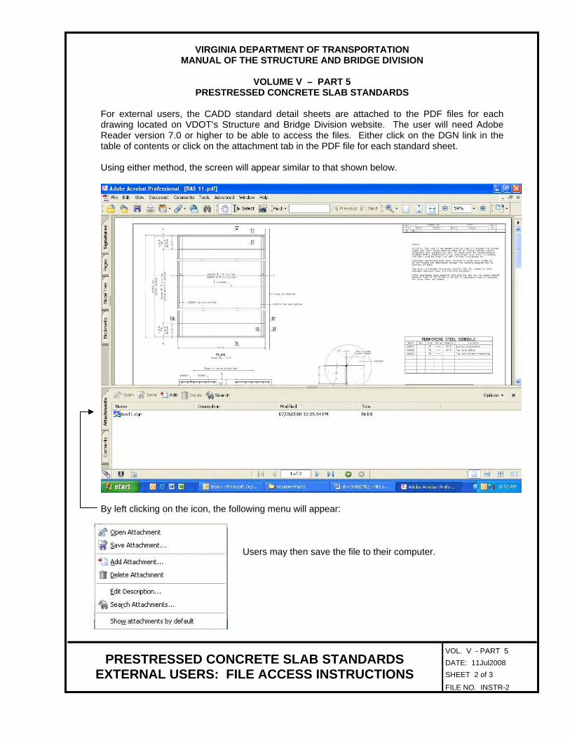
For external users, the CADD standard detail sheets are attached to the PDF files for each drawing located on VDOT’s Structure and Bridge Division website. The user will need Adobe Reader version 7.0 or higher to be able to access the files. Either click on the DGN link in the table of contents or click on the attachment tab in the PDF file for each standard sheet.
Using either method, the screen will appear similar to that shown below.
By left clicking on the icon, the following menu will appear:
Users may then save the file to their computer.
VOL. V - PART 5 DATE: 11Jul2008 SHEET 3 of 3
PRESTRESSED CONCRETE SLAB STANDARDS EXTERNAL USERS: FILE ACCESS INSTRUCTIONS
FILE NO. INSTR-3
VIRGINIA DEPARTMENT OF TRANSPORTATION
MANUAL OF THE STRUCTURE AND BRIDGE DIVISION
VOLUME V – PART 5 PRESTRESSED CONCRETE SLAB STANDARDS
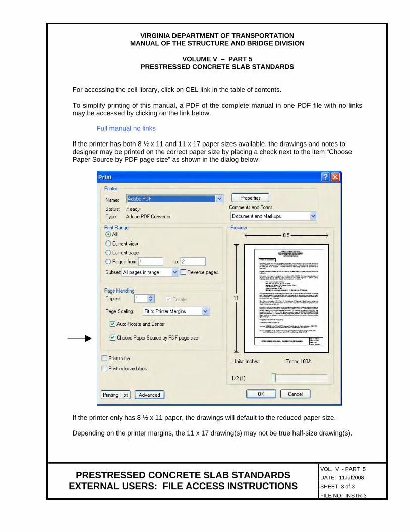
For accessing the cell library, click on CEL link in the table of contents. To simplify printing of this manual, a PDF of the complete manual in one PDF file with no links may be accessed by clicking on the link below. Full manual no links If the printer has both 8 ½ x 11 and 11 x 17 paper sizes available, the drawings and notes to designer may be printed on the correct paper size by placing a check next to the item “Choose Paper Source by PDF page size” as shown in the dialog below:
If the printer only has 8 ½ x 11 paper, the drawings will default to the reduced paper size. Depending on the printer margins, the 11 x 17 drawing(s) may not be true half-size drawing(s).

1’-8" 1’-8"
Face of curb Face of curb
See Detail A See Detail B
1"
TRANSVERSE SECTION
ELEVATION
1" min.
6"
elastomeric pad
DETAIL B
/
2�
"2�
"�
"�
"
� x 5 x 5 preformed
PL 1 x 5 x 5
PLAN
L roadway and L bridge
Prestressed concrete slabs
Interior slabsExterior slab Exterior slab
C C
DETAIL A
6" 6"
�"
�"
�"3"
4"
�"
/
non-shrink grout
Fill with high strength
C
for transverse tendon
L 2" o precast holeC
Approved chuck
for �" o strand
C
tendons are tensioned
grout after transverse
be filled with non-shrink
Recess of exterior slab shall
L transverse tendon
�"
�"
applied directly over it
with two coat of epoxy-resin
waterproofing membrane strip
Primer and prefabricated
shear key
Symm. about L
waterproofing
applied two coat epoxy-resin
Limits of precast fabricator
Not to scale
SUPERSTRUCTURE
S&B DIV
See Drip Detail
1"
DRIP DETAIL
1�"
�"
�"
transverse tendon centerlines.
Voids shall terminate 2’-6" from end of span and 5" on either side of
Specifications.
Slabs shall have drains as required by Section 405.05 of the
minimum compressive strength of 5000 psi within 24 hours.
accordance with Section 218.03(d) of the Specifications having a
The grout in the shear keys shall be a non-shrink grout in
grout has reached a minimum strength of 4000 psi.
shall not be done until all grouting of keys are completed and the
Post tensioning of transverse tendons and the casting of parapets
bottoms of shear keys.
leakage of grout into precast holes for transverse tendons or from
without interruption for each span. Care shall be taken to prevent
All grouting of shear keys shall be done in one continuous operation
grouting of shear keys.
aggregate by means of sandblasting and pre-wetted prior to the
All keyway surfaces shall be cleaned of all dirt, laitance and loose
of prestressed concrete slabs.
Cost of deck and joint waterproofing shall be included in the price
ments of Section 405 and Section 416 of the Specifications.
Entire deck shall be waterproofed in accordance with the require-
nuts, washers and 1" x 5" x 5" steel plates shall be galvanized.
strand. The rod shall have a washer and nut at each end. Rods,
2�" long threaded ends tensioned to 30,000 lbs. for the �" dia.
feet, substitute a �" dia. smooth rod conforming to ASTM A449 with
length of the strand used for transverse tendon is less than 20
strand (Polystrand CP or equal) tensioned to 31,600 lbs. When the
Transverse tendons shall be �" dia. coated, low-relaxation Grade 270
Type SM-2C.
entire overlay shall be made at the unit price for asphalt concrete
ness and Type IM-19.0D for the remaining portion. Payment for the
Asphalt concrete overlay shall be Type SM-12.5D for the top 2" thick-
NOTES:
Date Plan No. Sheet No.Designed: ...........
Drawn: ................
Checked: ............2012, Commonwealth of Virginiac
No. Description Date
STRUCTURE AND BRIDGE DIVISION
COMMONWEALTH OF VIRGINIA
DEPARTMENT OF TRANSPORTATION
Revisions
ROUTE
FEDERAL AID
PROJECT ROUTE PROJECT
STATE SHEET
NO.
VA.
STATEROUTE
FEDERAL AID
PROJECT ROUTE PROJECT
STATE SHEET
NO.
VA.
STATE
STRUCTURAL ENGINEER
RICHMOND, VA
VDOT S&B DIVISION
PS
S-1
A.d
gn
S&B DIV
S&B DIV
PS
S-1
A
PSS-1A
2% slope 2% slope
Asphalt overlayPoint of finished grade
08-07-2012

STANDARD PSS-1A: NOTES TO DESIGNER
VOL. V - PART 5
DATE: 07Aug2012
SHEET 2 of 2
FILE NO. PSS-1A-2
PRESTRESSED CONCRETE SLAB STANDARD
VOIDED SLABS – ASPHALT OVERLAY SUPERSTRUCTURE
NOTES TO DESIGNER:
Include standard PSS-2 in the plans when using this standard. Include standard PSS-3F in the plans when using F-shape parapet. The designer shall insure that the width of the pier cap or the seat of the abutment is sufficient for locating the anchor bolts. The designer should avoid whenever possible the mixing of 3’-0” and 4’-0” wide slab sections. For exterior slabs, use solid slab sections to avoid conflicts and problems with reinforcing steel for parapets/railings. Cells for completing the standard are located in pss.cel library.
ADD THE FOLLOWING NOTES, DIMENSIONS, DETAILS, ETC. TO STANDARD:
TRANSVERSE SECTION: Centerline of roadway is assumed to be centerline of bridge. Adjust as needed. Enter dimensions from face of curb/rail to centerline. Add size for exterior slab (e.g., 3’-0” x 21”). Add spacing of interior slabs (e.g., 6 – 4’-0” x 21” prestressed concrete voided slabs = 24”-0”). F-shaped parapet is shown. Replace with sidewalk, rail, etc. as needed. PLAN: Place appropriate cell from cell library, and enter dimensions for face of curb/rail to centerline and for width of parapet/railing. Add skew angle when appropriate and spacing of transverse tendons. Transverse spacing of transverse tendons shall be spaced as follows:
For spans < 50 feet: @ mid-span (3 ties) For spans > 50 feet: @ 1/4
points (5 ties)
ELEVATION: Place appropriate cell from cell library. OTHER DETAILS REQUIRED: Place appropriate exterior concrete slab detail with F-shape parapet from cell library or draw appropriate parapet/rail detail. Place appropriate concrete voided slab detail from cell library. Must agree with those indicated in TRANSVERSE SECTION.

1’-8" 1’-8"
Face of curb Face of curb
See Detail A See Detail B
TRANSVERSE SECTION
ELEVATION
1" min.
6"
elastomeric pad
DETAIL B
/
2�
"2�
"�
"�
"
� x 5 x 5 preformed
PL 1 x 5 x 5
PLAN
L roadway and L bridge
Prestressed concrete slabs
Interior slabsExterior slab Exterior slab
C C
DETAIL A
�"
�"
�"3"
4"
�"
/
non-shrink grout
Fill with high strength
C
for transverse tendon
L 2" o precast holeC
Approved chuck
for �" o strand
C
tendons are tensioned
grout after transverse
be filled with non-shrink
Recess of exterior slab shall
L transverse tendon
�"
�"
shear key
Symm. about L
Not to scale
SUPERSTRUCTURE
S&B DIV
See Drip Detail
1"
DRIP DETAIL
1�"
�"
�"
Date Plan No. Sheet No.Designed: ...........
Drawn: ................
Checked: ............2012, Commonwealth of Virginiac
No. Description Date
STRUCTURE AND BRIDGE DIVISION
COMMONWEALTH OF VIRGINIA
DEPARTMENT OF TRANSPORTATION
Revisions
ROUTE
FEDERAL AID
PROJECT ROUTE PROJECT
STATE SHEET
NO.
VA.
STATEROUTE
FEDERAL AID
PROJECT ROUTE PROJECT
STATE SHEET
NO.
VA.
STATE
STRUCTURAL ENGINEER
RICHMOND, VA
VDOT S&B DIVISION
PS
S-1
B.d
gn
S&B DIV
S&B DIV PSS-1B
PS
S-1
B
2% slope 2% slope
transverse tendon centerlines.
Voids shall terminate 2’-6" from end of span and 5" on either side of
of the Specifications.
Concrete voided slabs shall have drains as required by Section 405.05
minimum compressive strength of 5000 psi within 24 hours.
accordance with Section 218.03(d) of the Specifications having a
The grout in the shear keys shall be a non-shrink grout in
grout has reached a minimum strength of 4000 psi.
shall not be done until all grouting of keys are completed and the
Post tensioning of transverse tendons and the casting of parapets
bottoms of shear keys.
leakage of grout into precast holes for transverse tendons or from
without interruption for each span. Care shall be taken to prevent
All grouting of shear keys shall be done in one continuous operation
grouting of shear keys.
aggregate by means of sandblasting and pre-wetted prior to the
All keyway surfaces shall be cleaned of all dirt, laitance and loose
nuts, washers and 1" x 5" x 5" steel plates shall be galvanized.
strand. The rod shall have a washer and nut at each end. Rods,
2�" long threaded ends tensioned to 30,000 lbs. for the �" dia.
feet, substitute a �" dia. smooth rod conforming to ASTM A449 with
length of the strand used for transverse tendon is less than 20
strand (Polystrand CP or equal) tensioned to 31,600 lbs. When the
Transverse tendons shall be �" dia. coated, low-relaxation Grade 270
laitance, with surface intentionally roughened to an amplitude of �".
Top surfaces of all slabs shall be a clean concrete surface, free of
Class __.
All reinforcing bars shall be Corrosion Resistant Reinforcing steel,
deck/overlay shall be made at the unit price for Concrete Class A4.
28 day compressive strength of 4000 psi. Payment for the concrete
Concrete for the deck/overlay shall be Class A4 having a minimum
NOTES:
Point of finished grade
08-07-2012
deck depth
__" concrete
Concrete deck
Concrete deck

STANDARD PSS-1B: NOTES TO DESIGNER
VOL. V - PART 5
DATE: 07Aug2012
SHEET 2 of 3
FILE NO. PSS-1B-2
PRESTRESSED CONCRETE SLAB STANDARD
VOIDED SLABS – CONCRETE DECK SUPERSTRUCTURE
NOTES TO DESIGNER:
Include standard PSS-2 in the plans when using this standard. Include standard PSS-3F in the plans when using F-shape parapet. The designer shall insure that the width of the pier cap or the seat of the abutment is sufficient for locating the anchor bolts. The designer should avoid whenever possible the mixing of 3’-0” and 4’-0” wide slab sections. For exterior slabs, use solid slab sections to avoid conflicts and problems with reinforcing steel for parapets/railings. Cells for completing the standard are located in pss.cel library.
ADD THE FOLLOWING NOTES, DIMENSIONS, DETAILS, ETC. TO STANDARD:
TRANSVERSE SECTION: Centerline of roadway is assumed to be centerline of bridge. Adjust as needed. Enter dimensions from face of curb/rail to centerline. Add size for exterior slab (e.g., 3’-0” x 21”). Add spacing of interior slabs (e.g., 6 – 4’-0” x 21” prestressed concrete voided slabs = 24”-0”). F-shaped parapet is shown. Replace with sidewalk, rail, etc. as needed. Add the depths of concrete deck. Add the steel reinforcing bars to concrete deck. For 5” thick concrete decks, provide single layer of reinforcement. For 71/2” thick concrete decks, provide two layers of reinforcement. PLAN: Place appropriate cell from cell library, and enter dimensions for face of curb/rail to centerline and for width of parapet/railing. Add skew angle when appropriate and spacing of transverse tendons. Transverse spacing of transverse tendons shall be spaced as follows:
For spans < 50 feet: @ mid-span (3 ties) For spans > 50 feet: @ 1/4
points (5 ties)
ELEVATION: Place appropriate cell from cell library.

STANDARD PSS-1B: NOTES TO DESIGNER
VOL. V - PART 5
DATE: 07Aug2012
SHEET 3 of 3
FILE NO. PSS-1B-3
PRESTRESSED CONCRETE SLAB STANDARD
VOIDED SLABS – CONCRETE DECK SUPERSTRUCTURE
NOTES: Complete second note by adding the Class I, II or III of corrosion resistant reinforcing steel required. For additional information on corrosion resistant reinforcing steel (CRR), see Structure and Bridge Division Memorandum (current IIM-S&B-81). OTHER DETAILS REQUIRED: Place appropriate exterior concrete slab detail with F-shape parapet from cell library or draw appropriate parapet/rail detail. Place appropriate concrete voided slab detail from cell library. Must agree with those indicated in TRANSVERSE SECTION.

Mark No.
#5
REINFORCING STEEL SCHEDULE
SizeSlab Size Length Location
SL0501
SR03
SR03
ST03
#3
#3
#3
/
A A
B
B
ANCHOR DETAIL
5"
/
SECTION A-A VIEW B-B
PLAN
Face of exterior slab
PART PLAN OF MEMBER
PART PLAN OF BEARINGS
Midspan
CAMBER DIAGRAM
Strand Type
Relaxation Strands
Slab
Size
No. of Strands
Row
1 2 3 4 5 6 7
Row Row Row Row Row Row Y1 Y2 Y3 Y4 Y5 Y6 Y7
Total number
of strands
per slab
Prestressing
force per
strand-lbs.in. in. in. in. in. in. in.
/
SECTION E-E
SECTION E-E
/
Net camber
N
in.
Plant application of approved epoxy mortar
applied over entire width of all members
Surface shall conform with
bridge seat bearing areas
Ends shall be truly vertical after members are
erected in their final postion in the structure
12"
12"
SLABS ON GRADIENT IN EXCESS OF 1%
SECTION F-F
See joint detail
asphalt joint filler
45
Face of exterior slab
3"
D
D
C C
/
SECTION C-C
VIEW D-D
PLAN
SUPERSTRUCTURE
PSS-2
PS
S-2
2�" min.
1�" min.
PL � x 6 x 7
PL � x 4 x 5
� PL
� (�)
PL � x 6 x 7
1�" min.
2�"
2�" min.
5�" min.
PRESTRESSING STEEL DATA TABLE
ALTERNATE ANCHOR DETAIL
�" preformed
�" o Low -
to slab
To be parallel
L8 x 6 x � x 10"
L 1�" o hole in washer PL
L 1�" x 3" slot in plate for
1�" o swedged anchor bolt
set 15" in masonry. Drill and
grout anchor bolt after
placement of slab.
/
/
Non rigid tubing typ.
L 1�" o hole in washer PL
L 1�" x 3" slot in plate for
1�" o swedged anchor bolt
set 15" in masonry. Drill and
grout anchor bolt after
placement of slab.
/
/
3�
"3�
"
2�" cl. typ.
SR03 series
2�"
1’-4" min. lap
SL0501
Symm. about L slab
Y7
Y6
Y5
Y4
Y3
Y2
Y1
Row 7
Row 6Row 5Row 4
Row 3Row 2
Row 1
3" min.Min. spacing 2"
/
/
C
Pin o
2�"
2�"
SR03
SR03
SR03
SR03
Top longitudinal
Not to scale
1�" cl.
Top and Bottom Transverse
L 2 - �" o boltsC
elastomeric pad
�" min. thick
typ.
1�" min
C
C
C
joint sealer
Hot poured
L pier and jointC
joint filler
1" preformed
of the Specifications
with Section 405
finished in accordance
Slab ends shall be
70 Durometer hardness
bearing pads
6 x 9 x � elastomeric
bridge seat
Top of
shear connectors
2 - �" o x 5" stud
C
C
2" +-
2" +-
C
C
C
is made = N
when stress transfer
Expected net camber
L storage supportsC
the end of slab
Measured normal to
Showing location of �" o strands
Top of bridge seat
Threaded insert for �" o bolt
/
/
S&B DIV
S&B DIV
S&B DIV
ST03
SL0501
Date Plan No. Sheet No.Date
STRUCTURE AND BRIDGE DIVISION
COMMONWEALTH OF VIRGINIA
DEPARTMENT OF TRANSPORTATION
Threaded insert
for �" o bolt
1"
Joint filler
JOINT DETAIL
�"
�"
joint sealer
Hot poured
breaker
Bond
SL0501 and ST03 SR03 and SR03
of reinforcing steel
Showing location
08-07-2012
each row see table below.
For number of strands in
L prestressing strands.
See Note 6.
L anchor.
bevel as needed
washer PL
� x 4 x 5
See Note 6.
L anchor.
bevel as needed
washer PL
� x 4 x 5
and warpage of plates
passes to prevent damage to concrete
Ample time shall be allowed between
Date Plan No. Sheet No.Designed: ...........
Drawn: ................
Checked: ............2012, Commonwealth of Virginiac
No. Description Date
STRUCTURE AND BRIDGE DIVISION
COMMONWEALTH OF VIRGINIA
DEPARTMENT OF TRANSPORTATION
Revisions
ROUTE
FEDERAL AID
PROJECT ROUTE PROJECT
STATE SHEET
NO.
VA.
STATEROUTE
FEDERAL AID
PROJECT ROUTE PROJECT
STATE SHEET
NO.
VA.
STATE
STRUCTURAL ENGINEER
RICHMOND, VA
VDOT S&B DIVISION
pss2.d
gn
clear 2" o hole for transverse tendon.
9. SR03 series may be slighty shifted as directed by the Engineer to
be included in other bid items.
full bearing of the slab on all the pads. Cost of adjustment shall
make such adjustment as directed by the Engineer to insure the
elevations may be needed. It is the Contractor’s responsibility to
8. Due to construction tolerances, adjustment to the bridge seat
strength of �" o threaded bolt.
7. Threaded inserts when embedded as shown shall develop full
connectors.
minimum concrete cover of 2" for threaded inserts or stud shear
6. L Anchor may be shifted as approved by the Engineer to provide
Engineer for approval.
5. The Contractor shall submit prestressing strand pattern to the
ASTM A709 grade 36 and shall be galvanized.
4. All steel in Anchor Detail except stud shear connectors shall be
their shape as shown on the plans by an approved epoxy mortar.
3. Slab corners damaged during construction shall be restored to
Class __.
2. All reinforcing bars shall be Corrosion Resistant Reinforcing Steel,
the stirrup may be made from one single bar.
1. In lieu of splicing several reinforcing bars to form each stirrup,
Notes:

VOL. V - PART 5
PRESTRESSED CONCRETE SLAB STANDARD
VOIDED SLABS SUPERSTRUCTURE
NOTES TO DESIGNER: Cells for completing the standard are located in pss.cel library.
ADD THE FOLLOWING NOTES, DIMENSIONS, DETAILS, ETC. TO STANDARD: PART PLAN OF MEMBER: Place appropriate part plan of member from cell library. Replace letters shown with rebars or spacings as may be appropriate with data from tables below: For 0° skew:
Slab size A B C 1 3 spa. @ 9” = 2’-3” 3’-0” x 15” SR0301 4 /2”
DATE: 31Aug2007 SHEET 2 of 3
STANDARD PSS-2: NOTES TO DESIGNER FILE NO. PSS-2-2
3’-0” x 18” SR0302 4 1 3 spa. @ 9” = 2’-3” /2” 1 3 spa.@ 9” = 2’-3” 3’-0” x 21” SR0303 4 /2”
4” 4 spa. @ 10” = 3’-4” 4’-0” x 15” SR0301 4” 4 spa. @ 10” = 3’-4” 4’-0” x 18” SR0302 4” 4 spa. @ 10” = 3’-4” 4’-0” x 21” SR0303
For skews > 0°:
Slab size A B C D 3 spa.@ 10” = 2’-6” 3’-0” x 15” SR0304 ST0301 SR0301 3 spa. @ 10” = 2’-6” 3’-0” x 18” SR0305 ST0301 SR0302
3 spa.@ 10” = 2’-6” 3’-0” x 21” SR0306 ST0301 SR0303
For all skews:
E Slab size Over 0° to 15° Over 15° to 30° Over 30° to 45°
3’-0” x 15” 4’-0” x 15” 3’-0” x 18”
2 spa. @ 6” = 12” 3 spa. @ 6” = 1’-6” 5 spa. @ 6” = 2’-6”
4’-0” x 18” 3’-0” x 21” 4’-0” x 21”
2 spa. @ 6” = 12” 4 spa. @ 6” = 2’-0” 7 spa. @ 6” = 3’-6”
4’-0” x 15” SR0304 ST0302 SR0301 4 spa. @ 101/2” = 3’-6” 4’-0” x 18” SR0305 ST0302 SR0302 4 spa.@ 101/2” = 3’-6” 4’-0” x 21” SR0306 ST0302 SR0303 4 spa. @ 101/2” = 3’-6”

STANDARD PSS-2: NOTES TO DESIGNER
VOL. V - PART 5
DATE: 07Aug2012
SHEET 3 of 3
FILE NO. PSS-2-3
PRESTRESSED CONCRETE SLAB STANDARD
VOIDED SLABS SUPERSTRUCTURE
ADD THE FOLLOWING NOTES, DIMENSIONS, DETAILS, ETC. TO STANDARD (cont’d):
PART PLAN OF BEARINGS: Place appropriate part plan of bearings from cell library. PRESTRESSING STEEL DATA TABLE: Complete table. Note strand type is shown as 7/16” diameter. Change if required. REINFORCING STEEL SCHEDULE: Complete table and replace letters shown with dimensions with data from table below.
REINFORCING STEEL SCHEDULE
Slab size Mark Size
Dimension A
Dimension B
Skew angle
0° over 0° to 15°
over 15° to 30°
over 30° to 45°
All slab sizes SL0501 #5 L (span length) ------
3’-0” x 15” SR0301 #3 1’-111/2” ------ ------ ------ 1’-01/8”
3’-0” x 18” SR0302 #3 1’-111/2” ------ ------ ------ 1’-31/8”
3’-0” x 21” SR0303 #3 1’-111/2” ------ ------ ------ 1’-61/8”
3’-0” x 15” SR0304 #3 ------ 2’-0” 2’-17/8” 2’-57/8” 1’-01/8”
3’-0” x 18” SR0305 #3 ------ 2’-0” 2’-17/8” 2’-57/8” 1’-31/8”
3’-0” x 21” SR0306 #3 ------ 2’-0” 2’-17/8” 2’-57/8” 1’-61/8”
4’-0” x 15” SR0301 #3 2’-51/2” ------ ------ ------ 1’-01/8”
4’-0” x 18” SR0302 #3 2’’-51/2” ------ ------ ------ 1’-31/8”
4’-0” x 21” SR0303 #3 2’-51/2” ------ ------ ------ 1’-61/8”
4’-0” x 15” SR0304 #3 ------ 2’-61/4” 2’-87/8” 3’-23/8” 1’-01/8”
4’-0” x 18” SR0305 #3 ------ 2’-61/4” 2’-87/8” 3’-23/8” 1’-31/8”
4’-0” x 21” SR0306 #3 ------ 2’-61/4” 2’-87/8” 3’-23/8” 1’-61/8”
3’-0” x 15”, x 18”, x 21” ST0301 #3 ------ 2’-81/8” 2’-113/4” 3’-77/8” ------
4’-0” x 15”, x 18”, x 21” ST0302 #3 ------ 3’-81/2” 4’-15/8” 5’-03/4” ------
NOTES: Complete note 2 by adding the Class I, II or III of corrosion resistant reinforcing steel required. For additional information on corrosion resistant reinforcing steels (CRR), see Structure and Bridge Division Memorandum (current IIM-S&B-81).

B B
A
A
B B
CC
2"
2"
1"
12"
ELEVATION
ABUTMENTS
PIERS
D D
12"
3" 4" 4"
Cast against end of slab
2"
3"7" 4 spa. @ 6"
= 2’-0"
3 spa. @
4" = 12"
L joint
L groove3’-7"
End of parapet
for payment
E
E
F
F
Max. spacing = 12"
RL04 series RL04 series
Min. lap
1’-3" typ.
RL0401
5�"2’-3�"
Max. spacing
= 12"
SECTION B-BFull Scale
sides of parapet.
Groove detail for both
�" �
"
�"
/Mark Length Pin o Location
Parapet
Parapet
Parapet
Parapet
Parapet
Parapet
RV0401
RV0502
RV0503
RV0504
RV0505
RL0401
5’-2"
3’-7"
2’-0"
REINFORCING STEEL SCHEDULE
RV0401 RV0505
12"
1’-
1"
RV0504
SizeNo.
#4
#5
#5
#4
#5
#5
#4
4’-2"
2’-7"
1’-9"
Parapet
1’-
8�
"
11�
"
1’-
8�
"
11�
"
2"
9�
"
9�
"
RV0503RV0502
3�"
3�"
Dimensions in bending diagram are out to out of bars, except as shown.
5�"
5�"
2’-
5�
"
2’-
6�
"
7�
"
2�"
5�"
7�
"
2�"
5�"
4�"
3�"
3�"
2’-
6"
2’-
5�
"
ABUTMENTS PIERS
PART PLAN
TYPICAL FOR SKEWED CROSSING
SECTION A-A
SECTION A-A
ALTERNATE REINFORCING STEEL
Dimensions are out-to-out of wires.
SECTION F-F
4"
RV0503
1’-8"
4�"8"
2�"
4�"
RV0401
10"
R
7"
1’-
10"
2’-
9"
RV0502
2�" cl.
1�" cl.
Face of curb
Barrier delineator
2" max. cl.
1�" min. cl.
RV0502
RV0503
RL04 series
cl.
2" max.
cl.
1�" min.
cl.
2" max.
cl.
1�" min.
2"
4�"
3�
" 3�
"
2"2
"4 spa.
@ 6"
= 2’-
0"
4 spa.
@ 6"
= 2’-
0"
6 x varies x W10 x W8
Welded wire fabric
2�
"cl.
RV0505
RV0401
RL0401
2"
SECTION E-EReinforcing steel not shown
3�
"
7"
3�
"
1�
"
1�
"
9�
"
Joint filler
1"
SECTION D-D
Joint detail for both
sides of parapet
Bond breaker
Silicone sealer
SECTION C-C
Deflection joint detail forboth sides of parapet
Full Scale
Full Scale
�"
�"
�"
�"
�"
Scale: 1" = 1’-0" unless otherwise noted
series
RL04
RV0504
PSS-3F
for all concrete above roadway slab.
Gross concrete quantities (C.Y.) = Lin. ft. x 0.110
PS
S-3F
2"
C
C
L groove and
L deflection joint
C
C C
C
1’-3" deep
deflection joint
Open
3"
12"12"
RL04
�"
typ.
�" R
C
CONCRETE PARAPET (F-SHAPE)
CAST-IN-PLACE
RV0502 N.F., RV0503 F.F. and RV0401
RV0503 at each space
RV0401, RV0502 and
SECTION E-EHoles and bolts not shown. For details
not shown, see Section A-A.
RV0503
RL04 series
RV0401
RV0502
08-07-2012
For details not shown, see Section A-A.
series
RL04
Bend in field
1’-6"
8"
6’-9�"
L permissible construction joint
C
1’-
8"
in the shaded area
Apply bond breaker
End of slab
7’-3"
see notes.
L bolts,
1’-
9�
" min.
1’-
10�
" m
ax.
2’-0"
1’-2"
6" 6" 4 spa. @ 6"
= 2’-0"
and RV0401
RV0504 N.F., RV0505
see notes.
L bolts,
see notes.
L holes,
Date Plan No. Sheet No.Designed: ...........
Drawn: ................
Checked: ............2012, Commonwealth of Virginiac
No. Description Date
STRUCTURE AND BRIDGE DIVISION
COMMONWEALTH OF VIRGINIA
DEPARTMENT OF TRANSPORTATION
Revisions
ROUTE
FEDERAL AID
PROJECT ROUTE PROJECT
STATE SHEET
NO.
VA.
STATEROUTE
FEDERAL AID
PROJECT ROUTE PROJECT
STATE SHEET
NO.
VA.
STATE
STRUCTURAL ENGINEER
RICHMOND, VA
VDOT S&B DIVISION
pss3f.d
gn
C
cross slopes and slab depths.
Contractor shall adjust the reinforcing steel as required for other
on a standard �" per foot cross slope and a 8�" slab depth. The
vertical planes. The reinforcing steel shown has been detailed based
Plan dimensions shown are measured in the respective horizontal and
to be drilled and installed when rub rail is attached.
Bolts, where shown, shall be �" dia. expansion anchor bolts, 6" long
pipe.
Holes, where shown, shall be formed with sleeves of 1�" dia. nominal
Terminal walls are detailed to take quardrail attachment GR-FOA-2.
All concrete shall be Class A4.
for installation.
The Contractor shall determine all dimensions and details necessary
to be facing oncoming traffic.
for parapet. Reflective surface of barrier delineator, in all instances,
the Specifications. Cost of delineator to be included in the price bid
Barrier delineator size, color, and spacing to be in accordance with
joints shall not exceed three groove spaces.
Spacing of grooves to be approximately 8’-0". Spacing of deflection
Class __.
All reinforcing bars shall be Corrosion Resistant Reinforcing Steel,
of parapet.
Rounded edges with 1" radius may be used in lieu of bevels along top
Notes:
Central Office.
is on file in the
standard drawing
sealed and signed
A copy of the original
Aug. 7, 2012
On the date of
Lic. No. 010487
Julius F.J. Volgyi Jr.
Sealed and Signed by:

STANDARD PSS-3F: NOTES TO DESIGNER
VOL. V - PART 5
DATE: 07Aug2012
SHEET 2 of 2
FILE NO. PSS-3F-2
PRESTRESSED CONCRETE SLAB STANDARD
VOIDED SLABS CAST-IN-PLACE PARAPET (F-SHAPE)
NOTES TO DESIGNER:
Standard is to be used as an insertable sheet when F-shape parapets are used. Terminal wall is detailed on abutment. If an initial bituminous overlay is used on the bridge at the time of construction, vertical dimensions and dimensions for reinforcing steel may need to be adjusted The vertical dimensions and dimensions for reinforcing steel shown on this standard are established from the top of the roadway surface for a 1” thick bituminous overlay at the face of parapet curb, 1/4” per foot cross slope and a 15” slab depth. If the thickness of the bituminous overlay at the face of parapet curb is greater than 1”, vertical dimensions and dimensions for reinforcing steel will need to be adjusted. For example if a 2” overlay at the curb is set , the 4” curb dimension and the overall 2’-9” height of the parapet would need to be adjusted to 5” and 2’-10” respectively (Section A-A). In addition, the 91/2” and 1’-10” height of the bolts would need to be adjusted to 101/2” and 1’-11” respectively (Section E-E).
ADD THE FOLLOWING NOTES, DIMENSIONS, DETAILS, ETC. TO STANDARD:
SECTION A-A: Modify vertical dimensions (4” curb and 2’-9” parapet height) as noted above if an initial overlay is used on bridge. SECTION E-E: Modify vertical dimensions (91/2” curb and 1’-10” bolt locations) as noted above if an initial overlay is used on bridge. REINFORCING STEEL SCHEDULE: Modify bars if needed due to slab depth, cross slope or initial overlay if used on bridge. NOTES: Complete second note by adding the Class I, II or III of corrosion resistant reinforcing steel required. For additional information on corrosion resistant reinforcing steels (CRR), see Structure and Bridge Division Memorandum (current IIM-S&B-81).

PRESTRESSED CONCRETE SLAB STANDARDS CELL LIBRARY: PSS.CEL
INDEX OF CELLS
VOL. V - PART 5
DATE: 07Aug2012
SHEET 1 of 1
FILE NO. CELLINDEX-1
PRESTRESSED CONCRETE SLAB STANDARDS
CELL LIBRARY: PSS.CEL
INDEX OF CELLS CELL NAME FILE NO. DATE BRG1.................................. PSSCELL-11 ....................................................................... 07Aug2012 BRG2L ............................... PSSCELL-12 ....................................................................... 07Aug2012 BRG2R ............................... PSSCELL-12 ....................................................................... 07Aug2012 ELEV .................................. PSSCELL-9 ......................................................................... 07Aug2012 ELEVL ................................ PSSCELL-10 ....................................................................... 07Aug2012 ELEVR ............................... PSSCELL-9 ......................................................................... 07Aug2012 EP15A ................................ PSSCELL-3 ......................................................................... 07Aug2012 EP15B ................................ PSSCELL-4 ......................................................................... 07Aug2012 EP15C ................................ PSSCELL-5 ......................................................................... 07Aug2012 EP15D ................................ PSSCELL-6 ......................................................................... 07Aug2012 EP18A ................................ PSSCELL-3 ......................................................................... 07Aug2012 EP18B ................................ PSSCELL-4 ......................................................................... 07Aug2012 EP18C ................................ PSSCELL-5 ......................................................................... 07Aug2012 EP18D ................................ PSSCELL-6 ......................................................................... 07Aug2012 EP21A ................................ PSSCELL-3 ......................................................................... 07Aug2012 EP21B ................................ PSSCELL-4 ......................................................................... 07Aug2012 EP21C ................................ PSSCELL-5 ......................................................................... 07Aug2012 EP21D ................................ PSSCELL-6 ......................................................................... 07Aug2012 ERDL .................................. PSSCELL-7 ......................................................................... 07Aug2012 ERD2L ................................ PSSCELL-7 ......................................................................... 07Aug2012 ERD2R ............................... PSSCELL-8 ......................................................................... 07Aug2012 ERD3L ................................ PSSCELL-8 ......................................................................... 07Aug2012 ERD3R ............................... PSSCELL-9 ......................................................................... 07Aug2012 RPINL ................................. PSSCELL-10 ....................................................................... 07Aug2012 RPINR ................................ PSSCELL-11 ....................................................................... 07Aug2012 RPLN .................................. PSSCELL-10 ....................................................................... 07Aug2012 VS15A ................................ PSSCELL-1 ......................................................................... 07Aug2012 VS15B ................................ PSSCELL-2 ......................................................................... 07Aug2012 VS18A ................................ PSSCELL-1 ......................................................................... 07Aug2012 VS18B ................................ PSSCELL-2 ......................................................................... 07Aug2012 VS21A ................................ PSSCELL-1 ......................................................................... 07Aug2012 VS21B ................................ PSSCELL-2 ......................................................................... 07Aug2012

PRESTRESSED CONCRETE SLAB STANDARDS CELL LIBRARY: PSS.CELL
CELLS
VOL. V - PART 5
DATE: 07Aug2012
SHEET 1 of 12
FILE NO. PSSCELLS-1
CELL CELL NAME CELL DESCRIPTION VS15A 3’-0” x 15” concrete voided slab . detail. Use with standard PSS-1A and PSS-1B. (approx. 0.25 of actual cell size) VS18A 3’-0” x 18” concrete voided slab detail. Use with standard PSS-1A and PSS-1B. (approx. 0.25 of actual cell size) VS21A 3’-0” x 21” concrete voided slab detail. Use with standard PSS-1A and PSS-1B. (approx. 0.25 of actual cell size)

PRESTRESSED CONCRETE SLAB STANDARDS CELL LIBRARY: PSS.CELL
CELLS
VOL. V - PART 5
DATE: 07Aug2012
SHEET 2 of 12
FILE NO. PSSCELLS-2
CELL CELL NAME CELL DESCRIPTION VS15B 4’-0” x 15” concrete voided slab detail. Use with standard PSS-1A and PSS-1B. (approx. 0.25 of actual cell size) VS18B 4’-0” x 18” concrete voided slab detail. Use with standard PSS-1A and PSS-1B. (approx. 0.25 of actual cell size) VS21B 4’-0” x 21” concrete voided slab detail. Use with standard PSS-1A and PSS-1B. (approx. 0.25 of actual cell size)

PRESTRESSED CONCRETE SLAB STANDARDS CELL LIBRARY: PSS.CELL
CELLS
VOL. V - PART 5
DATE: 07Aug2012
SHEET 3 of 12
FILE NO. PSSCELLS-3
CELL CELL NAME CELL DESCRIPTION EP15A Exterior 3’-0” x 15” concrete slab detail. Use with standard PSS-1A. (approx. 0.32 of actual cell size) EP18A Exterior 3’-0” x 18” concrete slab detail. Use with standard PSS-1A. (approx. 0.32 of actual cell size) EP21A Exterior 3’-0” x 21” concrete slab detail. Use with standard PSS-1A. (approx. 0.32 of actual cell size)

PRESTRESSED CONCRETE SLAB STANDARDS CELL LIBRARY: PSS.CELL
CELLS
VOL. V - PART 5
DATE: 07Aug2012
SHEET 4 of 12
FILE NO. PSSCELLS-4
CELL CELL NAME CELL DESCRIPTION EP15B Exterior 4’-0” x 15” concrete slab detail. Use with standard PSS-1A. (approx. 0.32 of actual cell size) EP18B Exterior 4’-0” x 18” concrete slab detail. Use with standard PSS-1A. (approx. 0.32 of actual cell size) EP21B Exterior 4’-0” x 21” concrete slab detail. Use with standard PSS-1A. (approx. 0.32 of actual cell size)

PRESTRESSED CONCRETE SLAB STANDARDS CELL LIBRARY: PSS.CELL
CELLS
VOL. V - PART 5
DATE: 07Aug2012
SHEET 5 of 12
FILE NO. PSSCELLS-5
CELL CELL NAME CELL DESCRIPTION EP15C Exterior 3’-0” x 15” concrete slab detail with concrete deck. Use with standard PSS-1B. (approx. 0.32 of actual cell size) EP18C Exterior 3’-0” x 18” concrete slab detail with concrete deck. Use with standard PSS-1B. (approx. 0.32 of actual cell size) EP21C Exterior 3’-0” x 21” concrete slab detail with concrete deck. Use with standard PSS-1B. (approx. 0.32 of actual cell size)

PRESTRESSED CONCRETE SLAB STANDARDS CELL LIBRARY: PSS.CELL
CELLS
VOL. V - PART 5
DATE: 07Aug2012
SHEET 6 of 12
FILE NO. PSSCELLS-6
CELL CELL NAME CELL DESCRIPTION EP15D Exterior 4’-0” x 15” concrete slab detail with concrete deck. Use with standard PSS-1B. (approx. 0.32 of actual cell size) EP18D Exterior 4’-0” x 18” concrete slab detail with concrete deck. Use with standard PSS-1B. (approx. 0.32 of actual cell size) EP21D Exterior 4’-0” x 21” concrete slab detail with concrete deck. Use with standard PSS-1B. (approx. 0.32 of actual cell size)

PRESTRESSED CONCRETE SLAB STANDARDS CELL LIBRARY: PSS.CELL
CELLS
VOL. V - PART 5
DATE: 07Aug2012
SHEET 7 of 12
FILE NO. PSSCELLS-7
CELL CELL NAME CELL DESCRIPTION ERDL Plan of slab with 0° skew. Use with standard PSS-1. (approx. 0.40 of actual cell size) ERD2L Plan of slab with left skew equal to or less than 10°. Use with standard PSS-1. (approx. 0.40 of actual cell size)

PRESTRESSED CONCRETE SLAB STANDARDS CELL LIBRARY: PSS.CELL
CELLS
VOL. V - PART 5
DATE: 07Aug2012
SHEET 8 of 12
FILE NO. PSSCELLS-8
CELL CELL NAME CELL DESCRIPTION ERD2R Plan of slab with right skew equal to or less than 10°. Use with standard PSS-1. (approx. 0.40 of actual cell size) ERD3L Plan of slab with left skew greater than 10°. Use with standard PSS-1. (approx. 0.40 of actual cell size)

PRESTRESSED CONCRETE SLAB STANDARDS CELL LIBRARY: PSS.CELL
CELLS
VOL. V - PART 5
DATE: 07Aug2012
SHEET 9 of 12
FILE NO. PSSCELLS-9
CELL CELL NAME CELL DESCRIPTION ERD3R Plan of slab with right skew greater than 10°. Use with standard PSS-1. (approx. 0.40 of actual cell size) ELEV Elevation of slab for 0° skew. Use with standard PSS-1. (approx. 0.40 of actual cell size) ELEVR Elevation of slab with right skew. Use with standard PSS-1. (approx. 0.40 of actual cell size)

PRESTRESSED CONCRETE SLAB STANDARDS CELL LIBRARY: PSS.CELL
CELLS
VOL. V - PART 5
DATE: 07Aug2012
SHEET 10 of 12
FILE NO. PSSCELLS-10
CELL CELL NAME CELL DESCRIPTION ELEVL Elevation of slab with left skew. Use with standard PSS-1. (approx. 0.40 of actual cell size) RPLN Part plan of reinforcing details for concrete slab member with 0° skew. Use with standard PSS-2. (approx. 0.50 of actual cell size) RPINL Part plan of reinforcing details for concrete slab member with left skew greater than 0°. Use with standard PSS-2. (approx. 0.50 of actual cell size)

PRESTRESSED CONCRETE SLAB STANDARDS CELL LIBRARY: PSS.CELL
CELLS
VOL. V - PART 5
DATE: 07Aug2012
SHEET 11 of 12
FILE NO. PSSCELLS-11
CELL CELL NAME CELL DESCRIPTION RPINR Part plan of reinforcing details for concrete slab member with right skew greater than 0°. Use with standard PSS-2. (approx. 0.50 of actual cell size) BRG1 Part plan of bearings for con- crete slab member with 0° skew. Use with standard PSS-2 (approx. 0.50 of actual cell size)

PRESTRESSED CONCRETE SLAB STANDARDS CELL LIBRARY: PSS.CELL
CELLS
VOL. V - PART 5
DATE: 07Aug2012
SHEET 12 of 12
FILE NO. PSSCELLS-12
CELL CELL NAME CELL DESCRIPTION BRG2R Part plan of bearings for con- crete slab members with right skew greater than 0°. Use with standard PSS-2. (approx. 0.50 of actual cell size) BRG2L Part plan of bearings for con- crete slab members with left skew greater than 0°. Use with standard PSS-2. (approx. 0.50 of actual cell size)