Embed Size (px)
Citation preview

RINAVia Corsica, 12 - 16128 Genova - ItalyTel. +39 01053851 - Fax: +39 0105351000E-MAIL [email protected] - WEB www.rina.org
Rules for the Classification of ShipsEffective from 1 January 2012
Part AClassification and Surveys

© RINA S.p.A. - All rights reserved
GENERAL CONDITIONSDefinitions:"Rules" in these General Conditions means the documents belowissued by the Society:- Rules for the Classification of Ships or other special units;- Complementary Rules containing the requirements for product,plant, system and other certification or containing the require-ments for the assignment of additional class notations;- Rules for the application of statutory rules, containing the rules toperform the duties delegated by Administrations;- Guides to carry out particular activities connected with Services;- Any other technical document, as for example rule variations orinterpretations.“Services” means the activities described in Article 1 below, ren-dered by the Society upon request made by or on behalf of theInterested Party.“Society” or “RINA” means RINA S.p.A. and/or all the companiesin the RINA Group which provide the Services.“Surveyor” means technical staff acting on behalf of the Society inperforming the Services.“Interested Party” means the party, other than the Society, havingan interest in or responsibility for the Ship, product, plant or sys-tem subject to classification or certification (such as the owner ofthe Ship and his representatives, the ship builder, the enginebuilder or the supplier of parts to be tested) who requests the Ser-vices or on whose behalf the Services are requested.“Owner” means the registered Owner, the ship Owner, the man-ager or any other party with the responsibility, legally or contractu-ally, to keep the ship seaworthy or in service, having particularregard to the provisions relating to the maintenance of class laiddown in Part A, Chapter 2 of the Rules for the Classification ofShips or in the corresponding rules indicated in the specific Rules.“Administration” means the Government of the State whose flagthe Ship is entitled to fly or under whose authority the Ship isauthorised to operate in the specific case."Ship" means ships, boats, craft and other special units, as forexample offshore structures, floating units and underwater craft.Article 11.1. - The purpose of the Society is, among others, the classifica-tion and certification of ships and the certification of their partsand components.The Society:- sets forth and develops Rules;- publishes the Register of Ships;- issues certificates, statements and reports based on its surveyactivities.1.2. - The Society also takes part in the implementation of nationaland international rules and standards as delegated by various Gov-ernments.1.3. – The Society carries out technical assistance activities onrequest and provides special services outside the scope of classifi-cation, which are regulated by these general conditions, unlessexpressly excluded in the particular contract.Article 22.1. - The Rules developed by the Society reflect the level of itstechnical knowledge at the time they are published. Therefore, theSociety, though committed, also through its research and develop-ment services, to continuous updating, does not guarantee theymeet state-of-the-art science and technology at the time of publi-cation or that they meet the Society's or others' subsequent techni-cal developments.2.2. - The Interested Party is required to know the Rules on thebasis of which the Services are provided. With particular referenceto Classification Services, special attention is to be given to theRules concerning class suspension, withdrawal and reinstatement.In case of doubt or inaccuracy, the Interested Party is to promptlycontact the Society for clarification. The Rules for Classification of Ships are published on the Society'swebsite: www.rina.org.2.3. - The Society exercises due care and skill: - in the selection of its Surveyors- in the performance of its Services, taking into account the level ofits technical knowledge at the time the Services are performed.2.4. - Surveys conducted by the Society include, but are not lim-ited to, visual inspection and non-destructive testing. Unless other-wise required, surveys are conducted through samplingtechniques and do not consist of comprehensive verification ormonitoring of the Ship or of the items subject to certification. Thesurveys and checks made by the Society on board ship do not nec-essarily require the constant and continuous presence of the Sur-veyor. The Society may also commission laboratory testing,underwater inspection and other checks carried out by and under
the responsibility of qualified service suppliers. Survey practicesand procedures are selected by the Society based on its experi-ence and knowledge and according to generally accepted techni-cal standards in the sector.Article 33.1. - The class assigned to a Ship, like the reports, statements, cer-tificates or any other document or information issued by the Soci-ety, reflects the opinion of the Society concerning compliance, atthe time the Service is provided, of the Ship or product subject tocertification, with the applicable Rules (given the intended use andwithin the relevant time frame).The Society is under no obligation to make statements or provideinformation about elements or facts which are not part of the spe-cific scope of the Service requested by the Interested Party or on itsbehalf.3.2. - No report, statement, notation on a plan, review, Certificateof Classification, document or information issued or given as partof the Services provided by the Society shall have any legal effector implication other than a representation that, on the basis of thechecks made by the Society, the Ship, structure, materials, equip-ment, machinery or any other item covered by such document orinformation meet the Rules. Any such document is issued solelyfor the use of the Society, its committees and clients or other dulyauthorised bodies and for no other purpose. Therefore, the Societycannot be held liable for any act made or document issued byother parties on the basis of the statements or information given bythe Society. The validity, application, meaning and interpretationof a Certificate of Classification, or any other document or infor-mation issued by the Society in connection with its Services, isgoverned by the Rules of the Society, which is the sole subjectentitled to make such interpretation. Any disagreement on techni-cal matters between the Interested Party and the Surveyor in thecarrying out of his functions shall be raised in writing as soon aspossible with the Society, which will settle any divergence of opin-ion or dispute.3.3. - The classification of a Ship, or the issuance of a certificate orother document connected with classification or certification andin general with the performance of Services by the Society shallhave the validity conferred upon it by the Rules of the Society atthe time of the assignment of class or issuance of the certificate; inno case shall it amount to a statement or warranty of seaworthi-ness, structural integrity, quality or fitness for a particular purposeor service of any Ship, structure, material, equipment or machin-ery inspected or tested by the Society.3.4. - Any document issued by the Society in relation to its activi-ties reflects the condition of the Ship or the subject of certificationor other activity at the time of the check.3.5. - The Rules, surveys and activities performed by the Society,reports, certificates and other documents issued by the Society arein no way intended to replace the duties and responsibilities ofother parties such as Governments, designers, ship builders, man-ufacturers, repairers, suppliers, contractors or sub-contractors,Owners, operators, charterers, underwriters, sellers or intendedbuyers of a Ship or other product or system surveyed.These documents and activities do not relieve such parties fromany fulfilment, warranty, responsibility, duty or obligation (also of acontractual nature) expressed or implied or in any case incumbenton them, nor do they confer on such parties any right, claim orcause of action against the Society. With particular regard to theduties of the ship Owner, the Services undertaken by the Societydo not relieve the Owner of his duty to ensure proper maintenanceof the Ship and ensure seaworthiness at all times. Likewise, theRules, surveys performed, reports, certificates and other docu-ments issued by the Society are intended neither to guarantee thebuyers of the Ship, its components or any other surveyed or certi-fied item, nor to relieve the seller of the duties arising out of thelaw or the contract, regarding the quality, commercial value orcharacteristics of the item which is the subject of transaction.In no case, therefore, shall the Society assume the obligationsincumbent upon the above-mentioned parties, even when it isconsulted in connection with matters not covered by its Rules orother documents.In consideration of the above, the Interested Party undertakes torelieve and hold harmless the Society from any third party claim,as well as from any liability in relation to the latter concerning theServices rendered.Insofar as they are not expressly provided for in these GeneralConditions, the duties and responsibilities of the Owner and Inter-ested Parties with respect to the services rendered by the Societyare described in the Rules applicable to the specific Service ren-dered.

Article 44.1. – Any request for the Society's Services shall be submitted inwriting and signed by or on behalf of the Interested Party. Such arequest will be considered irrevocable as soon as received by theSociety and shall entail acceptance by the applicant of all relevantrequirements of the Rules, including these General Conditions.Upon acceptance of the written request by the Society, a contractbetween the Society and the Interested Party is entered into, whichis regulated by the present General Conditions.4.2. – In consideration of the Services rendered by the Society, theInterested Party and the person requesting the service shall bejointly liable for the payment of the relevant fees, even if the ser-vice is not concluded for any cause not pertaining to the Society.In the latter case, the Society shall not be held liable for non-fulfil-ment or partial fulfilment of the Services requested. In the event oflate payment, interest at the legal current rate increased by 2%may be demanded.4.3. - The contract for the classification of a Ship or for other Ser-vices may be terminated and any certificates revoked at therequest of one of the parties, subject to at least 30 days' notice tobe given in writing. Failure to pay, even in part, the fees due forServices carried out by the Society will entitle the Society to imme-diately terminate the contract and suspend the Services.For every termination of the contract, the fees for the activities per-formed until the time of the termination shall be owed to the Soci-ety as well as the expenses incurred in view of activities alreadyprogrammed; this is without prejudice to the right to compensa-tion due to the Society as a consequence of the termination.With particular reference to Ship classification and certification,unless decided otherwise by the Society, termination of the con-tract implies that the assignment of class to a Ship is withheld or, ifalready assigned, that it is suspended or withdrawn; any statutorycertificates issued by the Society will be withdrawn in those caseswhere provided for by agreements between the Society and theflag State.Article 55.1. - In providing the Services, as well as other correlated infor-mation or advice, the Society, its Surveyors, servants or agentsoperate with due diligence for the proper execution of the activity.However, considering the nature of the activities performed (seeart. 2.4), it is not possible to guarantee absolute accuracy, correct-ness and completeness of any information or advice supplied.Express and implied warranties are specifically disclaimed. Therefore, except as provided for in paragraph 5.2 below, and alsoin the case of activities carried out by delegation of Governments,neither the Society nor any of its Surveyors will be liable for anyloss, damage or expense of whatever nature sustained by any per-son, in tort or in contract, derived from carrying out the Services.5.2. – Notwithstanding the provisions in paragraph 5.1 above,should any user of the Society's Services prove that he has suffereda loss or damage due to any negligent act or omission of the Soci-ety, its Surveyors, servants or agents, then the Society will paycompensation to such person for his proved loss, up to, but notexceeding, five times the amount of the fees charged for the spe-cific services, information or opinions from which the loss or dam-age derives or, if no fee has been charged, a maximum of onehundred thousand Euro. Where the fees charged are related to anumber of Services, the amount of the fees will be apportioned forthe purpose of the calculation of the maximum compensation, byreference to the estimated time involved in the performance of theService from which the damage or loss derives. Any liability forindirect or consequential loss, damage or expense is specificallyexcluded. In any case, irrespective of the amount of the feescharged, the maximum damages payable by the Society will notbe more than 1 million Euro. Payment of compensation under thisparagraph will not entail any admission of responsibility and/orliability by the Society and will be made without prejudice to thedisclaimer clause contained in paragraph 5.1 above.5.3. - Any claim for loss or damage of whatever nature by virtue ofthe provisions set forth herein shall be made to the Society in writ-ing, within the shorter of the following periods: THREE MONTHSfrom the date on which the Services were performed or THREEMONTHS from the date on which the damage was discovered.Failure to comply with the above deadline will constitute an abso-lute bar to the pursuit of such a claim against the Society.Article 66.1. - Any dispute arising from or in connection with the Rules orwith the Services of the Society, including any issues concerningresponsibility, liability or limitations of liability of the Society, willbe determined in accordance with Italian Law and settled througharbitration assigned to a board of three arbitrators who will pro-ceed in compliance with the Rules of the Chamber of National
and International Arbitration of Milan. Arbitration will take placein Genoa, Italy.6.2. - However, for disputes concerning non-payment of the feesand/or expenses due to the Society for services, the Society shallhave the right to submit any claim to the jurisdiction of the Courtsof the place where the registered or operating office of the Inter-ested Party or of the applicant who requested the Service islocated.In the case of actions taken against the Society by a third partybefore a public Court, the Society shall also have the right to sum-mon the Interested Party or the subject who requested the Servicebefore that Court, in order to be relieved and held harmlessaccording to art. 3.5 above.Article 77.1. - All plans, specifications, documents and information pro-vided by, issued by, or made known to the Society, in connectionwith the performance of its Services, will be treated as confidentialand will not be made available to any other party other than theOwner without authorisation of the Interested Party, except as pro-vided for or required by any applicable international, European ordomestic legislation, Charter or other IACS resolutions, or orderfrom a competent authority. Information about the status andvalidity of class and statutory certificates, including transfers,changes, suspensions, withdrawals of class, recommendations/conditions of class, operating conditions or restrictions issuedagainst classed ships and other related information, as may berequired, may be published on the website or released by othermeans, without the prior consent of the Interested Party.Information about the status and validity of other certificates andstatements may also be published on the website or released byother means, without the prior consent of the Interested Party.7.2. - Notwithstanding the general duty of confidentiality owed bythe Society to its clients in clause 7.1 above, the Society's clientshereby accept that the Society will participate in the IACS EarlyWarning System which requires each Classification Society to pro-vide other involved Classification Societies with relevant technicalinformation on serious hull structural and engineering systems fail-ures, as defined in the IACS Early Warning System (but not includ-ing any drawings relating to the ship which may be the specificproperty of another party), to enable such useful information to beshared and used to facilitate the proper working of the IACS EarlyWarning System. The Society will provide its clients with writtendetails of such information sent to the involved ClassificationSocieties.7.3. - In the event of transfer of class, addition of a second class orwithdrawal from a double/dual class, the Interested Party under-takes to provide or to permit the Society to provide the other Clas-sification Society with all building plans and drawings, certificates,documents and information relevant to the classed unit, includingits history file, as the other Classification Society may require forthe purpose of classification in compliance with the applicablelegislation and relative IACS Procedure. It is the Owner's duty toensure that, whenever required, the consent of the builder isobtained with regard to the provision of plans and drawings to thenew Society, either by way of appropriate stipulation in the build-ing contract or by other agreement.In the event that the ownership of the ship, product or system sub-ject to certification is transferred to a new subject, the latter shallhave the right to access all pertinent drawings, specifications, doc-uments or information issued by the Society or which has come tothe knowledge of the Society while carrying out its Services, evenif related to a period prior to transfer of ownership.Pursuant and owing to Italian legislative decree 196/2003, theInterested Party declares that it has read the information sheet con-cerning the processing of personal data published on the society'swebsite and gives its consent to such processing, also for commer-cial information purposes.Article 88.1. – Should any part of these General Conditions be declaredinvalid, this will not affect the validity of the remaining provisions.8.2. - In the event of doubts concerning the interpretation of theseGeneral Conditions, the Italian text will prevail.Article 99.1. – When the Society provides its Services to a consumer - i.e. anatural person who does not act within the scope of his businessor professional activity - the following provisions do not apply: art.3.2. (as far as the Society is solely entitled to the interpretation ofthe Rules); art. 4.2., (as far as the payment of the fees is also duefor services not concluded due to causes not attributable to theInterested Party); art. 5.1. (as far as the exclusion of liability is con-cerned); art. 5.2.; art. 5.3.; and art. 6.1. (as far as the jurisdictionof a Board of Arbitrators based in Genoa is concerned).

EXPLANATORY NOTE TO PART A
1. Reference editionThe reference edition for Part A is the RINA Rules 2000 edition, which is effective from 1 June 2000 with the exception of Chapters 3 to 5, which are effective from 1 October 2000.
2. Amendments after the reference edition2.1 RINA Rules 2000 has been completely rewritten
and reorganised.
2.2 Except in particular cases, the Rules are updated and published annually.
3. Effective date of the requirements3.1 All requirements in which new or amended provi-
sions with respect to those contained in the refer-ence edition have been introduced are followed by a date shown in brackets.
The date shown in brackets is the effective date of entry into force of the requirements as amended by the last updating. The effective date of all those requirements not followed by any date shown in brackets is that of the reference edition.
3.2 Item 6 below provides a summary of the technical changes from the preceding edition. In general, this list does not include those items to which only edi-torial changes have been made not affecting the effective date of the requirements contained therein.
4. Rule Variations and CorrigendaUntil the next edition of the Rules is published, Rule Variations and/or corrigenda, as necessary, will be pub-lished on the RINA web site (www.rina.org). Except in particular cases, paper copies of Rule Variations or cor-rigenda are not issued.
5. Rule subdivision and cross-references5.1 Rule subdivision
The Rules are subdivided into six parts, from A to F.
Part A: Classification and Surveys
Part B: Hull and Stability
Part C: Machinery, Systems and Fire Protection
Part D: Materials and Welding
Part E: Service Notations
Part F: Additional Class Notations
Each Part consists of:• Chapters• Sections and possible Appendices• Articles• Sub-articles• Requirements
Figures (abbr. Fig) and Tables (abbr. Tab) are numbered in ascending order within each Section or Appendix.
5.2 Cross-references
Examples: Pt A, Ch 1, Sec 1, [3.2.1]or Pt A, Ch 1, App 1, [3.2.1] • Pt A means Part A
The part is indicated when it is different from the part in which the cross-reference appears. Otherwise, it is not indicated.• Ch 1 means Chapter 1
The Chapter is indicated when it is different from the chapter in which the cross-reference appears. Other-wise, it is not indicated.• Sec 1 means Section 1 (or App 1 means
Appendix 1 )
The Section (or Appendix) is indicated when it is differ-ent from the Section (or Appendix) in which the cross-reference appears. Otherwise, it is not indicated.• [3.2.1] refers to requirement 1, within sub-article 2
of article 3.
Cross-references to an entire Part or Chapter are not abbreviated as indicated in the following examples:• Part A for a cross-reference to Part A• Part A, Chapter 1 for a cross-reference to Chapter 1
of Part A.

6. Summary of amendments introduced in the edi-tion effective from 1 January 2012
Foreword
This edition of Part A contains amendments published ina special booklet enclosed with Circular 3618 dated 28/06/2011, whose effective date is 1 July 2011 or 1 Janu-ary 2012, with the exception of some modificationsissued with Rule Variation TCHU/2011/02 effectivefrom 1.8.2011 (see Ch 1, Sec 2, [6.14.25] and Table 3).
The date of entry into force of each new or amendeditem is shown in brackets after the number of the itemconcerned.
List of Chapters/Sections/Appendixes containingnew or modified items
CHAPTER 1
Section 2: Table 1; Table 2; Table 3; [3.2.2]; [4.3.6]; [4.3.7];[4.5]; [4.8.3]; [6.14.23] (NEW); [6.14.24] (NEW); [6.14.25](NEW);
CHAPTER 2
Section 1: [4.1.1]; Section 2: [2.5.5]; [2.6.2]; [2.9.1]; [3.3]; [4.8.5]; [5.4.4];
CHAPTER 3
Section 3: [2.2.1];Section 4: [2.1.6] (NEW); [3.1.3];Section 6: [2.1.6] (NEW);
CHAPTER 4
Section 1: Table 1;Section 2: [2.5.4] (NEW); [2.7] (NEW); Section 3: [1.1.1]; [2.3.3] (NEW); [2.5] (NEW); [2.6] (NEW); [3.4] (NEW);Section 4: [1.1.1]; [2.3.3] (NEW); [2.5] (NEW); [2.6] (NEW);Section 5: [1.1.1]; [2.1.2]; [2.5] (NEW); [3.1.1]; [3.2.1]; [3.4] (NEW); [5.1.4] (NEW);Section 6: [2.1.8] (NEW); [3.3], [3.4], [3.7] (NEW); [5.3.3];[7.2.3];Section 7: complete revision; Section 9: [2.5.4] (NEW); [2.7] (NEW);Section 10: [1.1.1]; [7]; [15] (NEW);
CHAPTER 5
Section 2: [12] (NEW);

RULES FOR THE CLASSIFICATION OF SHIPS
Part AClassification and Surveys
Chapters 1 2 3 4 5 6
Chapter 1 PRINCIPLES OF CLASSIFICATION AND CLASS NOTATIONS
Chapter 2 ASSIGNMENT, MAINTENANCE, SUSPENSION AND WITHDRAWAL OF CLASS
Chapter 3 SCOPE OF SURVEYS (all ships)
Chapter 4 SCOPE OF SURVEYS IN RESPECT OF THE DIFFERENT SERVICES OF SHIPS
Chapter 5 SCOPE OF SURVEYS RELATED TO ADDITIONAL CLASS NOTATIONS
Chapter 6 RETROACTIVE REQUIREMENTS FOR EXISTING SHIPS


RINA Rules 2012 3
CHAPTER 1PRINCIPLES OF CLASSIFICATION AND CLASS NOTATIONS
Section 1 General Principles of Classification
1 Principles of classification 31
1.1 Purpose of the Rules1.2 General definitions1.3 Meaning of classification, scope and limits1.4 Request for services1.5 Register of ships
2 Rules 32
2.1 Equivalence2.2 Effective date2.3 Novel features2.4 Interpretation2.5 Disagreement and appeal
3 Duties of the Interested Parties 33
3.1 International and national regulations3.2 Surveyor’s intervention3.3 Operation and maintenance of ships3.4 Flag and Port State Control inspections3.5 Use of measuring equipment and of service suppliers3.6 Spare parts3.7 Use of asbestos
Section 2 Classification Notations
1 General 36
1.1 Purpose of the classification notations1.2 Types of notations assigned
2 Main class symbol 36
2.1 Main class symbol
3 Construction marks 36
3.1 General3.2 List of construction marks
4 Service notations 37
4.1 General4.2 Cargo ships4.3 Bulk, ore and combination carriers4.4 Additional service features and corresponding design loading conditions for
bulk carriers4.5 Ships carrying liquid cargo in bulk4.6 Ships carrying passengers4.7 Ships for dredging activities4.8 Working ships4.9 Non-propelled and assisted propulsion units, sailing ships

4 RINA Rules 2012
4.10 Fishing vessels4.11 Miscellaneous units
5 Navigation and operating area notations 46
5.1 Navigation notations5.2 List of navigation notations5.3 Operating area notations
6 Additional class notations 47
6.1 General6.2 System of Trace and Analysis of Records (STAR)6.3 Availability of machinery (AVM)6.4 Automated machinery systems (AUT)6.5 Integrated ship systems (SYS)6.6 Monitoring equipment (MON)6.7 Comfort on board ships (COMF)6.8 Pollution prevention6.9 Refrigerating installations6.10 Navigation in ice (ICE CLASS)6.11 Navigation in ice (POLAR CLASS)6.12 WINTERIZATION (temp)6.13 Planned maintenance scheme and condition based maintenance (PMS/CBM)6.14 Other additional class notations
7 Other notations 55
7.1

RINA Rules 2012 5
CHAPTER 2ASSIGNMENT, MAINTENANCE, SUSPENSION AND WITHDRAWAL OF CLASS
Section 1 Assignment of Class
1 General 61
1.1 Main cases of assignment of class
2 New building procedure 61
2.1 Ships surveyed by the Society during construction2.2 Other cases2.3 Documentation
3 Ships classed after construction 63
3.1 General3.2 Transfer to the Society's class of a ship in service classed by another QSCS
Classification Society (IACS PR 1A)3.3 Transfer to the Society's class of a ship surveyed during construction by another
QSCS Classification Society at ship's delivery3.4 Addition of the Society's class to a ship in service classed by another QSCS
Classification Society3.5 Addition of the Society's class to a ship surveyed during construction by another
QSCS Classification Society at the ship's delivery3.6 Ships in service not classed by a QSCS Classification Society
4 Date of initial classification 68
4.1 Definitions
5 Reassignment of class 69
5.1 Ships in service classed by a QSCS Classification Society5.2 Ships in service not classed by a QSCS Classification Society
6 Double or dual class procedure 69
6.1 Definitions6.2 Procedure

6 RINA Rules 2012
Section 2 Maintenance of Class
1 General principles of surveys 70
1.1 Survey types1.2 Change of periodicity, postponement or advance of surveys1.3 Extension of scope of survey1.4 General procedure of survey1.5 Appointment of another Surveyor
2 Definitions and procedures related to surveys 71
2.1 General2.2 Terminology related to hull survey2.3 Procedural requirements for thickness measurements2.4 Agreement of firms for in-water survey2.5 Conditions for surveys2.6 Access to structures2.7 Equipment for surveys2.8 Surveys at sea and anchorage2.9 Repairs and maintenance during voyage2.10 Prompt and thorough repairs 2.11 Survey attendance requirements2.12 Procedure for imposing and clearing recommendations
3 Certificate of Classification: issue, validity, endorsement and renewal 79
3.1 Issue of Certificate of Classification3.2 Validity of Certificate of Classification, maintenance of class3.3 Endorsements of Class3.4 Status of surveys and recommendations
4 Class renewal survey 80
4.1 General principles4.2 Normal system4.3 Continuous survey system4.4 Planned maintenance scheme (PMS/CBM) for machinery
5 Other periodical surveys 81
5.1 General5.2 Annual surveys5.3 Intermediate surveys5.4 Bottom survey5.5 Tailshaft survey5.6 Boiler survey5.7 Links between anniversary dates and annual surveys, intermediate surveys and
class renewal surveys
6 Occasional surveys 84
6.1 General6.2 Damage and repair surveys6.3 Port State Control survey6.4 Conversions, alterations and repairs6.5 Quality System audits
7 Change of ownership 85
7.1
8 Lay-up and re-commissioning 85
8.1 General principles

RINA Rules 2012 7
9 Possible safety management system failures 86
9.1
Section 3 Suspension and Withdrawal of Class
1 General 87
1.1 Discontinuance of class1.2 Suspension of class1.3 Withdrawal of class1.4 Suspension/withdrawal of additional class notations
Appendix 1 CMS and PMS: Surveys Carried Out by the Chief Engineer
1 Documentation 90
1.1
2 Limits of the interventions 90
2.1
3 Procedure for carrying out surveys 91
3.1 General3.2 Main diesel engines3.3 Auxiliary diesel engines3.4 Reciprocating compressors3.5 Coolers, condensers, heaters3.6 Electrical switchboard3.7 a.c. and d.c. generators3.8 Other items (pumps, electric motors, etc.)
4 Records of surveys carried out 92
4.1
5 Confirmatory survey 92
5.1
6 Suspension of the Chief Engineer’s authorisation 92
6.1

8 RINA Rules 2012
Appendix 2 Thickness Measurements: Extent, Determination of Locations and Acceptance Criteria
1 General 93
1.1 Aim of the Appendix1.2 Scope of the Appendix
2 Rule requirements for the extent of measurements 93
2.1 General2.2 Class renewal survey: all ships except those submitted to ESP2.3 Class renewal survey: ships submitted to ESP or equivalent
3 Number and locations of measurements 95
3.1 General3.2 Locations of points
4 Acceptance criteria for thickness measurements 95
4.1 General4.2 Criteria4.3 Local and global strength criteria4.4 Buckling strength criterion4.5 Pitting
Appendix 3 Criteria for Longitudinal Strength of the Hull Girder
1 General 119
1.1
2 Calculation of transverse sectional areas of deck and bottom flanges of hull girder 119
2.1
3 Requirements for transverse section modulus of hull girder 119
3.1
4 Calculation criteria of section moduli of midship section of hull girder 119
4.1
5 Diminution limit of minimum longitudinal strength of ships in service 120
5.1
6 Oil tankers - Sampling method of thickness measurements for longitudinal strength evaluation and repair methods 120
6.1 Extent of longitudinal strength evaluation6.2 Sampling method of thickness measurement6.3 Additional measurements where the longitudinal strength is deficient6.4 Effective repair methods

RINA Rules 2012 9
CHAPTER 3SCOPE OF SURVEYS (ALL SHIPS)
Section 1 Survey for New Construction
1 Hull 125
1.1 General1.2 Definitions1.3 Application1.4 Personnel1.5 Survey of the hull structure1.6 Review of the shipyard1.7 Newbuilding survey planning1.8 Examination and test plan for newbuilding activities1.9 Proof of the consistency of surveys1.10 Ship Construction File1.11 Shipyard review record
Section 2 Survey for Assignment of Class of a Ship in Service
1 Surveys required by IACS Procedural Requirement PR1A 149
1.1 Transfer to the Society's class of a ship in service classed by another QSCS Classification Society
1.2 Addition of the Society's class to a ship in service classed by another QSCS Classification Society
1.3 Transfer to the Society's class of a ship surveyed during construction by another QSCS Classification Society at ship's delivery
1.4 Addition of the Society's class to a ship surveyed during construction by another QSCS Classification Society at ship's delivery
1.5 Ships of less than 100 gross tonnage1.6 Ships in service not classed with a QSCS Classification Society or not classed at
all1.7 Reassignment of class
Section 3 Annual Survey
1 General 152
1.1
2 Hull 152
2.1 Scope2.2 Hull and hull equipment2.3 Cargo hatch covers and coamings, weather decks and ship side plating above
the waterline2.4 Suspect areas2.5 Ballast tanks2.6 Additional requirements for single hold cargo ships (see Note 1 to [1.1.1] of Ch
4, Sec 8)

10 RINA Rules 2012
3 Machinery and systems 154
3.1 General machinery installations3.2 Boilers3.3 Electrical machinery and equipment3.4 Fire protection, detection and extinction
Section 4 Intermediate Survey
1 General 156
1.1
2 Hull 156
2.1
Section 5 Class Renewal Survey
1 General 158
1.1
2 Hull and hull equipment 158
2.1 Bottom survey2.2 Decks, hatch covers and equipment2.3 Holds and other dry compartments2.4 Tanks2.5 Thickness measurements2.6 Additional requirements for single hold cargo ships (see Note 2 to [1.1.1] of Ch
4, Sec 8)
3 Machinery and systems 162
3.1 General3.2 Main and auxiliary engines and turbines3.3 Reduction gears, main thrust and intermediate shaft(s)3.4 Pumps and other machinery items 3.5 Systems in machinery spaces3.6 Electrical equipment and installations3.7 Controls3.8 Fire protection, detection and extinction
Section 6 Bottom Survey
1 General 166
1.1
2 Bottom survey in dry condition 166
2.1 General requirements2.2 Bottom survey held within the scope of class renewal survey
3 Bottom in-water survey 166
3.1 General

RINA Rules 2012 11
Section 7 Tailshaft Survey
1 Survey of tailshafts 168
1.1 General1.2 Complete survey1.3 Modified survey
2 Periodical survey of other propulsion systems 168
2.1 Rotating and azimuth thrusters2.2 Vertical axis propellers2.3 Pump jet systems
Section 8 Boiler Survey
1 Steam boilers 170
1.1
2 Thermal oil heaters 170
2.1
Appendix 1 Class Requirements and Surveys of Laid-up Ships
1 General 172
1.1
2 Safety conditions 172
2.1
3 Preservation measures for lay-up and maintenance 172
3.1 General3.2 Exposed parts of the hull3.3 Internal spaces3.4 Deck fittings3.5 Machinery3.6 Electrical installations3.7 Steering gear3.8 Boilers3.9 Automation equipment
4 Lay-up site and mooring arrangements 175
4.1 General4.2 Recommendations for the lay-up site4.3 Recommendations for the mooring arrangements4.4 Review of the mooring arrangements
5 Surveys 176
5.1 Laying-up survey5.2 Annual lay-up condition survey5.3 Re-commissioning survey

12 RINA Rules 2012
CHAPTER 4SCOPE OF SURVEYS IN RESPECT OF THE DIFFERENT SERVICES OF SHIPS
Section 1 General
1 General 181
1.1
2 Service notations subject to additional surveys 181
2.1
Section 2 Bulk Carriers and Combination Carriers of Single Side Skin Construction
1 General 183
1.1 Application1.2 Documentation on board1.3 Reporting and evaluation of surveys1.4 Access to structures
2 Annual survey 185
2.1 General2.2 Hull and equipment2.3 Weather decks, hatch covers and coamings2.4 Cargo holds2.5 Ballast tanks2.6 Additional requirements after determining compliance with SOLAS regulation
XII/12 (water level detectors) and XII/13 (availability of pumping systems)2.7 Means of access
3 Intermediate survey - Hull items 187
3.1 General3.2 Ships between 5 and 10 years of age3.3 Ships between 10 and 15 years of age 3.4 Ships over 15 years of age
4 Class renewal survey 189
4.1 Survey program and preparation for survey4.2 Scope of survey4.3 Hatch covers and coamings4.4 Overall and close-up surveys4.5 Thickness measurements4.6 Tank testing4.7 Additional requirements after determining compliance with SOLAS regulation
XII/12 (water level detectors) and XII/13 (availability of pumping systems) 4.8 Survey Program4.9 Survey Planning Questionnaire

RINA Rules 2012 13
Section 3 Oil Tankers and Combination Carriers
1 General 206
1.1 Application1.2 Documentation on board1.3 Reporting and evaluation of surveys
2 Annual survey - Hull items 207
2.1 Hull and weather decks2.2 Cargo pump rooms and pipe tunnels2.3 Ballast tanks2.4 Emergency towing arrangement2.5 Means of access2.6 Safe access to bow
3 Annual survey - Cargo machinery items 208
3.1 Cargo area and cargo pump rooms3.2 Instrumentation and safety devices3.3 Inert gas system3.4 Steering capability
4 Intermediate survey - Hull items 209
4.1 Weather decks4.2 General4.3 Ships between 5 and 10 years of age4.4 Ships between 10 and 15 years of age4.5 Ships over 15 years of age
5 Intermediate survey - Cargo machinery items 210
5.1 Cargo area and cargo pump rooms5.2 Inert gas system
6 Class renewal survey - Hull items 210
6.1 Survey program and preparation for hull survey6.2 Scope of survey6.3 Overall and close-up surveys6.4 Thickness measurements6.5 Tank testing6.6 Cargo area and cargo pump rooms6.7 Emergency towing arrangement6.8 Survey Program6.9 Survey Planning Questionnaire
7 Class renewal survey - Cargo machinery items 220
7.1 Cargo area and cargo pump rooms7.2 Inert gas system

14 RINA Rules 2012
Section 4 Double Hull Oil Tankers
1 General 223
1.1 Application1.2 Documentation on board1.3 Reporting and evaluation of surveys
2 Annual survey - Hull items 224
2.1 Hull and weather decks2.2 Cargo pump rooms and pipe tunnels2.3 Ballast tanks2.4 Emergency towing arrangement2.5 Means of access2.6 Safe access to bow
3 Intermediate survey - Hull items 225
3.1 Weather decks3.2 General3.3 Ships between 5 and 10 years of age3.4 Ships between 10 and 15 years of age3.5 Ships exceeding 15 years of age
4 Class renewal survey - Hull items 226
4.1 Survey program and preparation for hull survey4.2 Scope of survey4.3 Overall and close-up surveys4.4 Thickness measurements4.5 Tank testing4.6 Cargo area and cargo pump rooms4.7 Emergency towing arrangement4.8 Survey Program4.9 Survey Planning Questionnaire
Section 5 Chemical Tankers
1 General 241
1.1 Application1.2 Documentation on board1.3 Reporting and evaluation of surveys
2 Annual survey - Hull items 242
2.1 Hull and weather decks2.2 Cargo pump rooms and pipe tunnels2.3 Ballast tanks2.4 Emergency towing arrangement2.5 Safe access to bow
3 Annual survey - Cargo machinery items 242
3.1 Cargo area and cargo pump rooms3.2 Instrumentation and safety devices3.3 Inert gas system and inert/padding/drying gas3.4 Steering capability
4 Intermediate survey - Hull items 243
4.1 Weather decks4.2 General4.3 Ships between 5 and 10 years of age

RINA Rules 2012 15
4.4 Ships between 10 and 15 years of age4.5 Ships over 15 years of age
5 Intermediate survey - Cargo machinery items 244
5.1 Cargo area and cargo pump rooms5.2 Inert gas system
6 Class renewal survey - Hull items 245
6.1 Survey program and preparation for hull survey6.2 Scope of survey6.3 Overall and close-up surveys6.4 Thickness measurements6.5 Tank testing6.6 Cargo area and cargo pump rooms6.7 Emergency towing arrangement6.8 Survey Program6.9 Survey Planning Questionnaire
7 Class renewal survey - Cargo machinery items 257
7.1 Cargo area and cargo pump rooms7.2 Inert gas system
Section 6 Liquefied Gas Carriers
1 General 259
1.1 Application
2 Annual survey - Hull items 259
2.1 Scope
3 Annual survey - Cargo installations items 260
3.1 General3.2 Weather decks and cargo handling rooms3.3 Other arrangements or devices3.4 Cargo area, cargo compressor rooms, cargo pump rooms3.5 Instrumentation and safety devices3.6 Inert gas/air drying systems3.7 Steering capability
4 Intermediate survey - Hull items 261
4.1 Schedule4.2 Scope
5 Intermediate survey - Cargo installation items 262
5.1 General5.2 Weather decks and cargo handling rooms5.3 Cargo area, cargo pump rooms, cargo compressor rooms5.4 Instrumentation and safety devices5.5 Inert gas system
6 Class renewal survey - Hull items 263
6.1 Schedule6.2 Scope of survey6.3 Extent of overall and close-up surveys6.4 Extent of thickness measurements6.5 Extent of tank testing6.6 Emergency towing arrangement

16 RINA Rules 2012
7 Class renewal survey - Cargo installation items 266
7.1 General7.2 Cargo containment7.3 Piping systems7.4 Cargo area, cargo pump rooms, cargo compressor rooms7.5 Inert gas system
Section 7 Ro-ro Cargo Ships, Passenger Ships, Ro-ro Passenger Ships
1 General 270
1.1 1.2 Application1.3 Definitions
2 Ro-ro cargo ships - Annual survey 270
2.1 Shell and inner doors 2.2 Internal platforms and ramps2.3 Fire protection, detection and extinction
3 Ro-ro cargo ships - Class renewal survey 272
3.1 Shell and inner doors 3.2 Internal platforms and ramps3.3 Fire protection, detection and extinction
4 Passenger ships - Annual survey 273
4.1 Waterlight bulkheads4.2 Openings in shell plating4.3 Lightweight survey
5 Passenger ships - Class renewal survey 273
5.1
6 Ro-ro passenger ships - Annual and class renewal surveys 273
6.1

RINA Rules 2012 17
Section 8 General Dry Cargo Ships
1 General 274
1.1 Application1.2 Reporting and evaluation of surveys
2 Annual survey 274
2.1 Scope2.2 Additional requirements for single hold cargo ships
3 Intermediate survey 275
3.1 Schedule3.2 Scope
4 Class renewal survey 276
4.1 Schedule 4.2 Scope of survey 4.3 Hatch covers and coamings 4.4 Extent of overall and close-up surveys 4.5 Extent of thickness measurements 4.6 Tank testing 4.7 Additional requirements for single hold cargo ships
Section 9 Double Skin Bulk Carriers
1 General 283
1.1 Application1.2 Documentation on board1.3 Reporting and evaluation of surveys
2 Annual survey 284
2.1 General2.2 Hull Structure and Equipment2.3 Weather decks, hatch covers and coamings2.4 Cargo holds2.5 Ballast tanks2.6 Additional requirements after determining compliance with SOLAS regulations
XII/12 (water level detectors) and XII/13 (availability of pumping systems)2.7 Means of access
3 Intermediate survey 285
3.1 General3.2 Ships between 5 and 10 years of age3.3 Ships between 10 and 15 years of age3.4 Ships over 15 years of age
4 Class renewal survey 287
4.1 Survey program and preparation for survey4.2 Scope of survey4.3 Hatch covers and coamings4.4 Overall and close-up surveys4.5 Thickness measurements4.6 Tank testing4.7 Additional requirements after determining compliance with SOLAS XII/12
(water level detectors) and XII/13 (availability of pumping systems)4.8 Survey Program4.9 Survey Planning Questionnaire

18 RINA Rules 2012
Section 10 Other Service Notations
1 General 304
1.1
2 Container ship or ship equipped for the carriage of containers 304
2.1 Annual survey2.2 Class renewal survey
3 Livestock carrier 304
3.1 Annual survey3.2 Class renewal survey
4 FLS tanker 304
4.1 Annual survey - Hull items4.2 Annual survey - Cargo machinery items4.3 Intermediate survey - Hull items4.4 Intermediate survey - Cargo machinery items4.5 Class renewal survey - Hull items4.6 Class renewal survey - Cargo machinery items
5 Dredging units 306
5.1 Annual survey5.2 Class renewal survey
6 Tug, salvage tug, escort tug 306
6.1 Annual survey6.2 Class renewal survey
7 Supply vessel 307
7.1 Supply vessel - Oil product or Supply vessel - Chemical product7.2 Supply vessel - Anchor handling or Supply vessel - Anchor handling stab
8 Fire-fighting ship 309
8.1 Annual survey8.2 Class renewal survey
9 Oil recovery ship 309
9.1 Annual survey9.2 Class renewal survey
10 Cable laying ship 310
10.1 Annual survey10.2 Class renewal survey
11 Fishing vessel 310
11.1 Annual survey11.2 Class renewal survey
12 Pipe laying ship 310
12.1 Annual survey12.2 Class renewal survey
13 Research ship 310
13.1 Annual and Class renewal survey
14 Cement carrier 311
14.1 Annual survey14.2 Class renewal survey

RINA Rules 2012 19
15 Asphalt tanker 311
15.1 Annual survey - Hull items15.2 Annual survey - Cargo machinery items15.3 Intermediate survey - Hull items15.4 Class renewal survey - Hull items15.5 Class renewal survey - Cargo machinery items
Appendix 1 Survey Reporting Principles for Ships Subject to Enhanced Survey Program
1 Survey reporting principles 313
1.1 General1.2 Issue of a survey report1.3 Purpose of reporting 1.4 Surveys split between different stations1.5 Identification of spaces and areas1.6 Items surveyed1.7 Thickness measurement report1.8 Longitudinal strength1.9 List of required repairs1.10 List of repairs carried out1.11 List of repairs not completed

20 RINA Rules 2012
CHAPTER 5SCOPE OF SURVEYS RELATED TO ADDITIONAL CLASS NOTATIONS
Section 1 General
1 General 317
1.1
2 Additional class notations subject to additional surveys 317
2.1
Section 2 STAR (System of Trace and Analysis of Records)
1 General 319
1.1 Application
2 STAR-HULL 319
2.1 Survey scope and periodicity
3 STAR-MACH 319
3.1 Survey scope and periodicity
Section 3 Availability of Machinery
1 General 320
1.1
2 Annual survey 320
2.1
3 Class renewal survey 320
3.1
Section 4 Automated Machinery Systems
1 General 321
1.1
2 Annual survey 321
2.1
3 Class renewal survey 321
3.1

RINA Rules 2012 21
Section 5 Integrated Ship Systems
1 General 322
1.1
2 Annual survey 322
2.1 All notations2.2 Notations SYS-NEQ and SYS-NEQ-12.3 Notation SYS-COM2.4 Notation SYS-IBS
3 Class renewal survey 323
3.1 All notations
Section 6 Monitoring Equipment
1 General 324
1.1 Application
2 MON-HULL 324
2.1 Annual and class renewal survey
3 MON-SHAFT 324
3.1 Tailshaft survey
Section 7 Pollution Prevention
1 General 325
1.1 Application
2 CLEAN-SEA 325
2.1 Annual and class renewal survey
3 CLEAN-AIR 326
3.1 Annual and class renewal survey
4 GREEN PLUS 326
4.1 Annual and class renewal survey
5 GREEN STAR 3 326
5.1 Annual and class renewal survey
6 LOW SOx (N) 328
6.1 Annual and class renewal survey

22 RINA Rules 2012
Section 8 Refrigerating Installations
1 General 329
1.1
2 Annual survey 329
2.1 General2.2 Refrigerating plant2.3 Refrigerated spaces2.4 Instrumentation and safety devices2.5 Notation -AIRCONT
3 Class renewal survey 330
3.1 General 3.2 Refrigerating plant3.3 Refrigerated spaces3.4 Instrumentation and safety devices3.5 Notation -AIRCONT
Section 9 Arrangements for Navigation in Ice - Ice Class and Polar Class
1 General 332
1.1
2 Class renewal survey 332
2.1 Thickness measurements2.2 Sea chests
Section 10 Winterisation (temp)
1 General 333
1.1
2 Annual survey 333
2.1 Anti-icing arrangements2.2 De-icing arrangements2.3 Anti-freezing arrangements2.4 Distribution switchboards for de-icing2.5 Heating equipment2.6 Tests2.7 Special equipment
Section 11 Other Notations
1 General 334
1.1
2 STRENGTHBOTTOM 334
2.1 Dry-docking survey
3 GRABLOADING and GRAB [X] 334
3.1 Class renewal survey
RINA Rules 2012 23
4 SPM 334
4.1 Annual survey4.2 Class renewal survey
5 DYNAPOS 334
5.1 Annual survey5.2 Class renewal survey
6 VCS 335
6.1 Annual survey6.2 Class renewal survey
7 COVENT 335
7.1 Annual survey7.2 Class renewal survey
8 CARGOCONTROL 335
8.1 Annual survey8.2 Class renewal survey
9 COAT-WBT 336
9.1 General9.2 Intermediate and class renewal surveys9.3 Coating damage and repairs
10 DIVINGSUPPORT 336
10.1 Annual survey10.2 Class renewal survey
11 HVSC 336
11.1 Annual and class renewal survey
12 FIRE 337
12.1 General
24 RINA Rules 2012
CHAPTER 6RETROACTIVE REQUIREMENTS FOR EXISTING SHIPS
Section 1 General
1 General 341
1.1 1.2 List of retroactive rule requirements
Section 2 Bulk Carriers, Ore Carriers and Combination Carriers
1 Requirements for the foremost cargo hold 343
1.1 Application1.2 Schedule for compliance1.3 Scantlings of the transverse bulkhead between the two foremost cargo holds1.4 Allowable hold loading of the foremost cargo hold with the same hold flooded1.5 Damage stability1.6 Alternative requirements1.7 Loading conditions, loading manuals and loading instruments
2 Requirements for all cargo holds 345
2.1 Application2.2 Longitudinal strength of hull girder2.3 Scantlings of tranverse bulkheads in all cargo holds2.4 Allowable hold loading in all cargo holds
3 Detection of water ingress into cargo holds 346
3.1 Requirements for installation of detectors3.2 Requirements for testing and survey
4 Strength and securing of small hatches on the exposed fore deck 346
4.1 General4.2 Application4.3 Implementation
5 Strength requirements for fore deck fittings and equipment 346
5.1 General5.2 Application5.3 Implementation
6 Cargo hatch cover securing arrangements for bulk carriers not built in accordance with Part B, Ch 9, Sec 7 347
6.1 General6.2 Application6.3 Implementation6.4 Securing Devices6.5 Stoppers6.6 Materials and Welding

RINA Rules 2012 25
7 Renewal criteria for side shell frames and brackets in cargo holds of single side skin bulk carriers and single side skin OBO carriers not built in accordance with Part E, Ch 4, Sec 3, [3.2] and Part E, Ch 4, Sec 3, [6.2] 348
7.1 General7.2 Application7.3 Implementation7.4 Ice strengthened ships7.5 Renewal or other measures7.6 Strength check criteria
Section 3 Ships Carrying Liquid Cargo in Bulk
1 General 357
1.1 Application1.2 Safe access to ship bows1.3 Secondary means of flow in the cargo tanks venting systems
Section 4 Passenger Ships, Ro-ro Passenger Ships and Ro-ro Cargo Ships
1 General 358
1.1 Application
2 Increased stability and watertight integrity 358
2.1
3 Side Shell Doors, Stern Doors, Bow Doors and Inner Doors 359
3.1 Side Shell Doors and Stern Doors3.2 Bow Doors and Inner Doors
Section 5 General Dry Cargo Ships
1 Strength and securing of small hatches on the exposed fore deck 361
1.1 General1.2 Application1.3 Implementation
2 Strength requirements for fore deck fittings and equipment 361
2.1 General2.2 Application2.3 Implementation
3 Changeover from the continuous to the normal system for hull class renewal survey 362
3.1 General

26 RINA Rules 2012
Section 6 Ships with Ice Class Notation
1 General 363
1.1 Definitions1.2 Application
2 Requirements to retain ICE CLASS notations 363
2.1 General
3 Other methods of determining KC or RCH 363
3.1 General
4 Draught limitation in ice 364
4.1 Warning triangle
Appendix 1 Technical Retroactive Requirements for Bulk Carriers
1 General 365
1.1
2 Evaluation of scantlings of the transverse watertight vertically corrugated bulkheads between the two foremost cargo holds 365
2.1 Application and definitions2.2 Load model2.3 Bending moment and shear force in the bulkhead corrugations2.4 Strength criteria2.5 Local details2.6 Steel renewal
3 Guidance on renewal/reinforcement of the transverse watertight vertically corrugated bulkhead between the two foremost cargo holds 373
3.1
4 Evaluation of allowable hold loading of the foremost cargo hold with the same cargo hold flooded 375
4.1 Application and definitions4.2 Load model4.3 Shear capacity of the double bottom of the foremost cargo hold4.4 Allowable hold loading

RINA Rules 2012 27
Appendix 2 Guidelines for the Thickness Measurements of Side Shell Frames and Brackets in Single Side Skin Bulk Carriers Subject to Compliance with the Requirements of Section 2, [7]
1 General 378
1.1
2 Zones of side shell frames and brackets 378
2.1
3 Pitting and grooving 378
3.1 General3.2 Assessment based upon area
4 Gauging methodology 379
4.1 General4.2 Gauging for Zones A, B and D - Web plating4.3 Gauging for Zone C - Web plating4.4 Gauging for sections a) and b) (flanges and side shell plating)
5 Report on thickness measurements of cargo hold frames 380
5.1


RINA Rules 2012 29
Part AClassification and Surveys
Chapter 1
PRINCIPLES OF CLASSIFICATION AND CLASSNOTATIONS
SECTION 1 GENERAL PRINCIPLES OF CLASSIFICATION
SECTION 2 CLASSIFICATION NOTATIONS


Pt A, Ch 1, Sec 1
RINA Rules 2012 31
SECTION 1 GENERAL PRINCIPLES OF CLASSIFICATION
1 Principles of classification
1.1 Purpose of the Rules
1.1.1 The Rules published by the Society give the require-ments for the assignment and the maintenance of class forseagoing ships.Class assigned to a ship reflects the discretionary opinion ofthe Society that the ship, for declared conditions of use andwithin the relevant time frame, complies with the Rulesapplicable at the time the service is rendered.Note 1: The general conditions of classification are laid down inthe “General Conditions” placed at the biginning of this Part.
1.1.2 (1/1/2008)The application criteria of the different parts of the presentRules are the following with the exceptions indicated in[1.1.3] and [1.1.4]:• Part A - Classification and Surveys applies to all ships.• Part B - Hull and Stability, Part C - Machinery, Systems
and Fire Protection, Part D - Materials and Welding andPart E - Service Notations apply to seagoing ships whosehull is of welded steel construction. Where necessary,the extent of application is more precisely defined ineach chapter of these parts of the Rules.
• Part F - Additional Class Notations applies, at therequest of the Interested Party, to all ships.
The classification of ships other than those dealt with in theabove-mentioned Parts B, C, D and E is covered by specificRules published by the Society.Note 1: As from 1 January 2007, the statutory requirements of theSOLAS Convention and/or national safety regulations, as applica-ble, regarding fire protection, detection and extinction (hereinafterreferred to as "fire protection statutory requirements") are no longermandatory for the purpose of classification, except where the Soci-ety carries out surveys relevant to fire protection statutory require-ments on behalf of the flag Administration. In such cases, fireprotection statutory requirements are considered a matter of classand therefore compliance with these requirements is also verifiedby the Society for classification purposes at class surveys.
In general, only IACS Unified Requirements in force related to fireprotection, detection and extinction have been retained as Rulerequirements within the scope of classification. Thus, the surveyrequirements for class surveys (annual, intermediate, class renewalsurveys and others) no longer include those related to fire protec-tion statutory requirements.
The above is applicable to all ships (new buildings and ships inservice) and therefore the scope of surveys as stipulated in thepresent Part A has also been reduced accordingly for all ships.
1.1.3 (1/4/2006)For the hull structures of ships contracted for constructionon or after 1 April 2006, the Common Structural Rules areto be applied in the following cases:• single side skin and double side skin bulk carriers with
unrestricted navigation, having length L of 90 m or
greater (as defined in Chapter 1, Sec 1, [1.1.2] of the"Common Structural Rules for Bulk Carriers"),
• double hull oil tankers of 150 m length or greater (asdefined in Section 1 of the "Common Structural Rulesfor Double Hull Oil Tankers").
1.1.4 (1/1/2008)Special consideration may be given in application of Rulerequirements relevant to periodical surveys of:
• the hull,
• machinery, including boilers,
• the outside of the ship's bottom and related items, and
• tailshafts,
for commercial ships owned or chartered by Governments,which are used in support of military operations or service.The above special consideration cannot be given in applica-tion of hull survey requirements regarding ESP ships.
1.2 General definitions1.2.1 (1/7/2009)The following general definitions are used in these Rules:
• Society means RINA S.p.A. and/or all the companies inthe RINA Group which provide the Services
• Rules means these Rules for the Classification of Shipsand documents issued by the Society serving the samepurpose
• Common Structural Rules means the "Common Struc-tural Rules for Bulk Carriers" and the "Common Struc-tural Rules for Double Hull Oil Tankers" adopted byIACS
• Surveyor means technical staff acting on behalf of theSociety to perform tasks in relation to classification andsurvey duties
• Survey means an intervention by the Surveyor forassignment or maintenance of class as defined inChapter 2, or interventions by the Surveyor within thelimits of the tasks delegated by the Administrations
• Administration means the Government of the Statewhose flag the ship is entitled to fly or the State underwhose authority the ship is operating in the specific case
• Interested Party means a party, other than the Society,having responsibility for the classification of the ship,such as the Owner of the ship and his representatives, orthe Shipbuilder, or the Engine Builder, or the Supplier ofparts to be tested
• QSCS Classification Society means a Classification Soci-ety which is subject to verification of compliance withthe IACS Quality System Certification Scheme (QSCS)
• Owner means the Registered Owner or the DisponentOwner or the Manager or any other party having theresponsibility to keep the ship seaworthy, having partic-
Pt A, Ch 1, Sec 1
32 RINA Rules 2012
ular regard to the provisions relating to the maintenanceof class laid down in Chapter 2
• Approval means the examination and acceptance by theSociety of documents, procedures or other items relatedto classification, verifying solely their compliance withthe relevant Rules requirements, or other referenceswhere requested
• Type approval means an approval process for verifyingcompliance with the Rules of a product, a group ofproducts or a system, and considered by the Society asrepresentative of continuous production
• Essential service is intended to mean a service necessaryfor a ship to proceed at sea, be steered or manoeuvred,or undertake activities connected with its operation, andfor the safety of life, as far as class is concerned.
1.3 Meaning of classification, scope and limits
1.3.1 The classification consists of:
• the development of Rules, guides and other documentsrelevant to the ship, structure, material, equipment,machinery and any other item covered by such docu-ments
• the examination of plans and calculations and the sur-veys, checks and tests intended to ensure that the shipmeets the Rules (refer to Ch 2, Sec 1)
• the assignment of class (see Ch 2, Sec 1) and issue of aCertificate of Classification, where the above Rules aremet
• the periodical, occasional and class renewal surveysperformed to verify that the ship in service meets theconditions for maintenance of class (see Ch 2, Sec 2).
1.3.2 The Rules, surveys performed, reports, certificatesand other documents issued by the Society, are in no wayintended to replace or alleviate the duties and responsibili-ties of other parties such as Administrations, Designers,Shipbuilders, Manufacturers, Repairers, Suppliers, Contrac-tors or Sub-contractors, actual or prospective Owners orOperators, Charterers, Brokers, Cargo-owners and Under-writers. The Society cannot therefore assume the obligationsarising from these functions, even when the Society is con-sulted to answer inquiries concerning matters not coveredby its Rules, or other documents.
The activities of such parties which fall outside the scope ofthe classification as set out in the Rules, such as design,engineering, manufacturing, operating alternatives, choiceof type and power of machinery and equipment, numberand qualification of crew or operating personnel, lines ofthe ship, trim, hull vibrations, spare parts including theirnumber, location and fastening arrangements, life-savingappliances, and maintenance equipment, remain thereforethe responsibility of those parties, even if these matters maybe given consideration for classification according to thetype of ship or additional class notation assigned.
The classification-related services and documents per-formed and issued by the Society do not relieve the partiesconcerned of their responsibilities or other contractual obli-gations expressed or implied or of any liability whatsoever,
nor do they create any right or claim in relation to the Soci-ety with regard to such responsibilities, obligations and lia-bilities. In particular, the Society does not declare theacceptance or commissioning of a ship or any part of it, thisbeing the exclusive responsibility of the Owner.
1.3.3 Unless otherwise specified, the Rules do not dealwith structures, pressure vessels, machinery and equipmentwhich are not permanently installed and used solely foroperational activities such as dredging or heavy load lifting,workshops or welding equipment, except for their effect onthe classification-related matters, as declared by the Inter-ested Party, such as fire protection and ship’s generalstrength.
During periods of construction, modification or repair, theunit is solely under the responsibility of the builder or therepair yard. As an example, the builder or repair yard is toensure that the construction, modification or repair activi-ties are compatible with the design strength of the ship andthat no permanent deformations are sustained.Note 1: Refer to [3.3] as regards the Owner’s responsibility formaintenance and operation of the ship in relation to the mainte-nance of class.
1.4 Request for services
1.4.1 Requests for interventions by the Society, such assuveys during construction, surveys of ships in service, tests,etc., are in principle to be submitted in writing and signedby the Interested Party. Such request implies that the appli-cant will abide by all the relevant requirements of the Rules,including its “General Conditions”.
The Society reserves the right to refuse or withdraw the classof any ship for which any applicable requirement of theRules is not complied with.
1.5 Register of ships
1.5.1 A Register of Ships is published periodically by theSociety. This publication, which is updated by the Society,contains the names of ships which have received the Certif-icate of Classification, as well as particulars of the classassigned and information concerning each ship.
2 Rules
2.1 Equivalence
2.1.1 The Society may consider the acceptance of alterna-tives to these Rules, provided that they are deemed to beequivalent to the Rules to the satisfaction of the Society.
2.2 Effective date2.2.1 The effective date of entry into force of any amendments tothe Rules is indicated on the inside front page of each Partof the Rules.
2.2.2 (1/7/2007)In principle, the applicable Rules for assignment of class toa new ship are those in force at the date when the contract

Pt A, Ch 1, Sec 1
RINA Rules 2012 33
for construction between the Owner and the shipbuilder issigned (see Note 1).
Note 1:
a) The date of "contract for construction" of a ship is the date onwhich the contract to build the ship is signed between the pro-spective Owner and the shipbuilder. This date and the con-struction numbers (i.e. hull numbers) of all the ships includedare to be declared to the Society by the party applying for theassignment of class to a new building.
b) The date of "contract for construction" of a series of ships,including specified optional ships for which the option is ulti-mately exercised, is the date on which the contract to build theseries is signed between the prospective Owner and the ship-builder. For the purpose of this issue, ships built under a singlecontract for construction are considered a "series of ships" ifthey are built to the same approved plans for classification pur-poses. However, ships within a series may have design altera-tions from the original design provided:
1) such alterations do not affect matters related to classifica-tion, or
2) if the alterations are subject to classification requirements,either these alterations comply with the classificationrequirements in effect on the date on which the alterationsare contracted between the prospective Owner and theshipbuilder or, in the absence of the alteration contract,they comply with the classification requirements in effecton the date on which the alterations are submitted to theSociety for approval.
The optional ships will be considered part of the same series ofsister ships, if the option is exercised not later than one yearafter the contract to build the series was signed.
c) If a contract for construction is later amended to include addi-tional ships or additional options, the date of "contract for con-struction" for such ships is the date on which the amendment tothe contract is signed between the prospective Owner and theshipbuilder. The amendment to the contract is to be consideredas a "new contract" to which a) and b) above apply.
d) If a contract for construction is amended to change the shiptype, the date of "contract for construction" of this modifiedship, or ships, is the date on which the revised contract or newcontract is signed between the Owner, or Owners, and theshipbuilder.
2.2.3 Special consideration may be given to applying newor modified rule requirements which entered into force sub-sequent to the date of the contract, at the discretion of theSociety and in the following cases:
• when a justified written request is received from theparty applying for classification
• when the keel is not yet laid and more than one year haselapsed since the contract was signed
• where it is intended to use existing previously approvedplans for a new contract.
2.2.4 The above procedures for application of the Rulesare, in principle, also applicable to existing ships in the caseof major conversions and, in the case of alterations, to thealtered parts of the ship.
2.2.5 The rule requirements related to assignment, mainte-nance and withdrawal of the class of ships already in opera-tion, are applicable from the date of their entry into force.
2.3 Novel features
2.3.1 The Society may consider the classification of shipsbased on or applying novel design principles or features, towhich the Rules are not directly applicable, on the basis ofexperiments, calculations or other supporting informationprovided to the Society. The specific limitations may thenbe indicated on the Certificate of Classification.
2.4 Interpretation
2.4.1 The Society alone is qualified to decide upon themeaning, interpretation and application of the Rules andother classification-related documents. No reference to theRules or other classification-related documents has anyvalue unless it involves, accompanies or follows the inter-vention of the Society.
2.5 Disagreement and appeal
2.5.1 Any technical disagreement with the Surveyor inconnection with the performance of his duties should beraised by the Interested Party as soon as possible.
The Interested Party may appeal in writing to the Society,which will subsequently consider the matter and announceits decision according to its established procedure.
3 Duties of the Interested Parties
3.1 International and national regulations
3.1.1 (1/7/2001)
The classification of a ship does not absolve the InterestedParty from compliance with any requirements issued byAdministrations and any other applicable international andnational regulations for the safety of life at sea and protec-tion of the marine environment.
3.1.2 Where requirements of International Conventions,such as SOLAS, ILLC, MARPOL, ILO or of IMO AssemblyResolutions, are quoted as excerpts, they are printed initalic type replacing the word “Administration” with “Soci-ety”.
When these requirements are quoted from such Interna-tional Conventions, they are printed in italic type.
In the event of disputes, the text of the International Con-ventions will prevail.
3.1.3 When authorised by the Administration concerned,the Society will act on its behalf within the limits of suchauthorisation. In this respect, the Society will take intoaccount the relevant national requirements, survey the ship,report and issue or contribute to the issue of the corre-sponding certificates.
The above surveys do not fall within the scope of the classi-fication of ships, even though their scope may overlap inpart and may be carried out concurrently with surveys forassignment or maintenance of class.

Pt A, Ch 1, Sec 1
34 RINA Rules 2012
3.1.4 (1/10/2007)
The IACS Unified Interpretations applicable to a ship and itsmachinery and equipment in accordance with the imple-mentation dates and provisions stated in the Unified Inter-pretations themselves will be applied, as appropriate, by theSociety when acting as a recognised organisation, author-ised by a flag State Administration to act on its behalf,unless the flag Administration provides its own interpreta-tion.
3.1.5 In the case of a discrepancy between the provisionsof the applicable international and national regulations andthose of the Rules, normally, the former take precedence.However, the Society reserves the right to call for the neces-sary adaptation to preserve the intention of the Rules or toapply the provisions of [1.4.1].
3.2 Surveyor’s intervention
3.2.1 Surveyors are to be given free access at all times toships which are classed or being classed, shipyards andworks, to carry out their interventions within the scope ofassignment or maintenance of class, or within the scope ofinterventions carried out on behalf of Administrations,when so delegated.
Free access is also to be given to auditors accompanying theSurveyors of the Society within the scope of the verticalaudits as required in pursuance of the Society’s internalQuality System or as required by external organizations.
3.2.2 Interested Parties are to take the necessary measuresfor the Surveyors’ inspections and testing to be carried outsafely. Interested Parties - irrespective of the nature of theservice provided by the Surveyors of the Society or othersacting on its behalf - assume with respect to such Surveyorsall the responsibility of an employer for his workforce suchas to meet the provisions of applicable legislation. As a rule,the Surveyor is to be constantly accompanied during sur-veys by personnel of the Interested Party. Refer also to Ch 2,Sec 2, [2.5] to Ch 2, Sec 2, [2.8].
3.2.3 The Certificate of Classification and/or other docu-ments issued by the Society remain the property of the Soci-ety. All certificates and documents necessary to theSurveyor’s interventions are to be made available by theInterested Party to the Surveyor on request.
3.2.4 During the phases of ship design and construction,due consideration should be given to rule requirements inrespect of all necessary arrangements for access to spacesand structures with a view to carrying out class surveys.Arrangements of a special nature are to be brought to theattention of the Society.
3.3 Operation and maintenance of ships
3.3.1 Operation of the ship (1/7/2001)
The classification of a ship is based on the understandingthat the ship is loaded and operated in a proper manner bycompetent and qualified crew or operating personnel
according to the loading, environmental, operating andother criteria on which classification is based.
In particular, it will be assumed that the draught of the shipin operating conditions will not exceed that correspondingto the freeboard assigned or the maximum approved for theclassification, that the ship will be properly loaded takinginto account both its stability and the stresses imposed onits structures and that cargoes will be properly stowed andsuitably secured. That the speed and course of the ship areadapted to the prevailing sea and weather conditionsaccording to the normal prudent seamanship and that theship is operated in accordance with the applicable interna-tional and national regulations for the prevention and con-tainment of marine pollution.
3.3.2 Maintenance of the shipAny document issued by the Society in relation to its interven-tions reflects the condition of the ship as found at the time andwithin the scope of the survey. It is the Interested Party’s respon-sibility to ensure proper maintenance of the ship until the nextsurvey required by the Rules. It is the duty of the Interested Partyto inform the Surveyor when he boards the ship of any events orcircumstances affecting the class.
3.3.3 Hull inspection and maintenance schemes (1/7/2008)
Hull inspection and maintenance schemes may be adoptedby the Owner as a means for maintaining compliance withclassification and statutory requirements between surveys.However, these schemes will not be accepted as an alterna-tive to, or a substitute for, the performance of required clas-sification and/or statutory surveys of the hull by theSurveyors of the Society, or of another duly authorised Soci-ety (see Note 1). No information received from the Ownerindicates that, where adopted, these schemes have provento be be free from any deficiencies.Note 1: The Surveyors may be assisted, where appropriate, by serv-ice suppliers as defined in the "Rules for the certification of servicesuppliers.
3.4 Flag and Port State Control inspections
3.4.1 Owner's duties (1/7/2007)When a ship is detained further to an inspection by a PortState Authority or the flag Administration, Owners are to:
• immediately report the outcome of this inspection to theSociety, and
• ask the Society to perform an occasional survey in orderto verify that the deficiencies, when related to the classof the ship or to the statutory certificates issued by theSociety on behalf of the flag Administration, are recti-fied and/or the necessary repair work is carried outwithin the due time.
Should the Owners fail to notify the Society of detention ofa ship, the Society reserves the right to suspend or withdrawits classification.
Where non-detainable deficiencies are found by the above-mentioned Authorities, Owners are to inform the Society,which may require the ship to be attended by a Surveyor forthe purpose of verifying the correction of the reported defi-ciencies, if deemed necessary.
Pt A, Ch 1, Sec 1
RINA Rules 2012 35
3.4.2 Co-operation with and assistance to inspecting Authorities (1/7/2008)
The Society will co-operate during Port State Controlinspections by:
a) liaising with Port State Control Authorities to ensure thatSurveyors are called in as appropriate when deficienciesrelated to class and statutory matters are found;
b) liaising with Port State Control Officers to ensure uni-formity of interpretation of class and statutory require-ments;
c) providing Port State Control Officers, upon request, withbackground information, extracts from reports pertinentto the inspection, and details of outstanding conditionsof class and statutory items;
d) liaising with the flag State in accordance with any prioragreement, and the Owner's representative and/or Com-pany, in order to ensure that both parties are fully awareof actions being taken that affect safety-related mattersof either a class or statutory nature.
Any request received from a Port State to attend on board aship is dealt with promptly and efficiently by the Society inorder to assist in the rectification of reported hardware defi-ciencies or other discrepancies.
Before attending on the ship, the Society will inform theCompany, either directly or through the Owner's represent-ative, of the purpose of the visit.
3.5 Use of measuring equipment and of service suppliers
3.5.1 GeneralFirms providing services on behalf of the Interested Party,such as measurements, tests and servicing of safety systemsand equipment, the results of which may form the basis forthe Surveyor’s decisions, are subject to the acceptance ofthe Society, as deemed necessary.
The equipment used during tests and inspections in work-shops, shipyards and on board ships, the results of whichmay form the basis for the Surveyor’s decisions, is to be cus-tomary for the checks to be performed. Firms are to individ-
ually identify and calibrate to a recognised national orinternational standard each piece of such equipment.
3.5.2 Simple measuring equipmentThe Surveyor may accept simple measuring equipment (e.g.rulers, tape measures, weld gauges, micrometers) withoutindividual identification or confirmation of calibration, pro-vided it is of standard commercial design, properly main-tained and periodically compared with other similarequipment or test pieces.
3.5.3 Shipboard measuring equipmentThe Surveyor may accept measuring equipment fitted onboard a ship (e.g. pressure, temperature or rpm gauges andmeters) and used in examination of shipboard machineryand/or equipment based either on calibration records orcomparison of readings with multiple instruments.
3.5.4 Other equipmentThe Surveyor may request evidence that other equipment(e.g. tensile test machines, ultrasonic thickness measure-ment equipment, etc) is calibrated to a recognised nationalor international standard.
3.6 Spare parts
3.6.1 It is the Owner’s responsibility to decide whetherand which spare parts are to be carried on board.
3.6.2 As spare parts are outside the scope of classification,the Surveyor will not check that they are kept on board,maintained in a satisfactory condition, or suitably protectedand lashed.
However, in the case of repairs or replacement, the spareparts used are to meet the requirements of the Rules as faras practicable; refer to Ch 2, Sec 2, [6.4.2].
3.7 Use of asbestos3.7.1 (1/1/2011)New installation of materials which contain asbestos is pro-hibited.

Pt A, Ch 1, Sec 2
36 RINA Rules 2012
SECTION 2 CLASSIFICATION NOTATIONS
1 General
1.1 Purpose of the classification notations
1.1.1 The classification notations give the scope accordingto which the class of the ship has been based and refer tothe specific rule requirements which are to be compliedwith for their assignment. In particular, the classificationnotations are assigned according to the type, service andnavigation of the ship and other criteria which have beenprovided by the Interested Party, when applying for classifi-cation.The Society may change the classification notations at anytime, when the information available shows that therequested or already assigned notations are not suitable forthe intended service, navigation and any other criteria takeninto account for classification.Note 1: Reference should be made to Sec 1, [1.3] on the limits ofclassification and its meaning.
1.1.2 The classification notations assigned to a ship areindicated on the Certificate of Classification, as well as inthe Register of Ships published by the Society.
1.1.3 (1/7/2008)Ships and units, other than those covered in Parts B, C, D, Eand F, are to comply with specific Rules published by theSociety, which also stipulate the relevant classification nota-tions.
1.1.4 The classification notations applicable to existingships conform to the Rules of the Society in force at the dateof assignment of class, as indicated in Ch 2, Sec 1. How-ever, the classification notations of existing ships may beupdated according to the currrent Rules, as far as applica-ble.
1.2 Types of notations assigned
1.2.1 The types of classification notations assigned to aship are the following:
a) main class symbol
b) construction marks
c) service notations with additional service features, asapplicable
d) navigation notations
e) operating area notations (optional)
f) additional class notations (optional)The different classification notations and their conditions ofassignment are listed in [2] to [6] below, according to theirtypes.
1.2.2 As an example, the classification notations assignedto a ship may be as follows (the kind of notation shown in
brackets does not form part of the classification notationindicated in the Register of Ships and on the Certificate ofClassification):
C ✠ HULL ✠ MACH
(main class symbol, construction marks)
oil tanker-chemical tanker-ESP-Flash point > 60°C
(service notation and additional service features)
Unrestricted navigation
(navigation notation)
✠ SYS - NEQ
(additional class notation).
2 Main class symbol
2.1 Main class symbol
2.1.1 The main class symbol expresses the degree of com-pliance of the ship with the rule requirements as regards itsconstruction and maintenance. There is one main classsymbol, which is compulsory for every classed ship.
2.1.2 (1/1/2009)The main class symbol C is assigned to ships built inaccordance with the requirements of the Rules or otherrules recognised as equivalent, and maintained in a condi-tion considered satisfactory by the Society. The period ofclass (or interval between class renewal surveys) assigned toa ship is maximum 5 years; see Ch 2, Sec 2, [4].
Except for special cases, class is assigned to a ship onlywhen the hull, propulsion and auxiliary machinery installa-tions, and equipment providing essential services have allbeen reviewed in relation to the requirements of the Rules.
Note 1: The symbol C with the 5 year class period is to be under-stood as being the highest class granted by the Society.
Note 2: The symbol C may be followed by the additional construc-tion feature light ship in case of ships or other units havingrestricted navigation notations and generally having length notgreater than 50 m as well as speed greater than 15 knots, whosehull scantlings and outfitting comply with the applicable require-ments of Chapters 3 and 6 of the "Rules for the Classification ofHigh Speed Craft", issued separately by the Society.
3 Construction marks
3.1 General
3.1.1 The construction mark identifies the procedureunder which the ship and its main equipment or arrange-ments have been surveyed for initial assignment of theclass. The procedures under which the ship is assigned oneof the construction marks are detailed in Ch 2, Sec 1.

Pt A, Ch 1, Sec 2
RINA Rules 2012 37
3.1.2 One of the construction marks defined below isassigned separately to the hull of the ship and its append-ages, to the machinery installation, and to some installa-tions for which an additional classification notation (see [6]below) is assigned.
The construction mark is placed before the symbol HULLfor the hull, before the symbol MACH for the machineryinstallations, and before the additional class notationgranted, when such a notation is eligible for a constructionmark.
When the same construction mark is assigned to both hulland machinery, the construction mark is assigned globallyto the ship without indication HULL and MACH after themain class symbol.
If the ship has no machinery installations covered by classi-fication, the symbol MACH is not granted and the construc-tion mark will be placed before the symbol HULL.
3.1.3 The construction marks refer to the original condi-tion of the ship. However, the Society may change the con-struction mark where the ship is subjected to repairs,conversion or alterations.
3.2 List of construction marks
3.2.1 The mark ✠ is assigned to the relevant part of theship, when it has been surveyed by the Society during itsconstruction in compliance with the new building proce-dure detailed in Ch 2, Sec 1, [2.1].
3.2.2 (1/7/2011)
The mark ✠ is assigned to the relevant part of the ship, whenthe latter is classed after construction in compliance withthe procedure detailed in Ch 2, Sec 1, [3.2] and it was builtunder the survey of a QSCS Classification Society and wasassigned by this Society a class deemed equivalent to thatdescribed in the Rules.
This mark is assigned to ships:
a) admitted to class in the course of construction surveyedby another QSCS Classification Society;
b) for which the procedure detailed in Ch 2, Sec 1, [3.2]does not apply, as it was disclassed from a QSCS Classi-fication Society for a period longer than six months, butwhich was built according to the Rules and under thesurvey of a QSCS Classification Society. In this case, theadmission to class survey is to confirm that the ship hasnot undergone conversions or modifications or altera-tions, which were not approved by a QSCS Classifica-tion Society.
3.2.3 The mark ● is assigned to the relevant part of theship, where the procedure for the assignment of classifica-tion is other than those detailed in [3.2.1] and [3.2.2], buthowever deemed acceptable.
4 Service notations
4.1 General
4.1.1 The service notations define the type and/or serviceof the ship which have been considered for its classifica-tion, according to the request for classification signed bythe Interested Party. At least one service notation is to beassigned to every classed ship.Note 1: The service notations applicable to existing ships conformto the Rules of the Society in force at the date of assignment ofclass. However, the service notations of existing ships may beupdated according to the current Rules, as far as applicable, at therequest of the Interested Party.
4.1.2 (1/4/2006)The assignment of any service notation to a new ship is sub-ject to compliance with general Rule requirements laiddown in Part B, Part C and Part D of the Rules and, for someservice notations, the additional requirements laid down inPart E and in the Common Structural Rules for bulk carriersand double hull oil tankers.
4.1.3 A ship may be assigned several different servicenotations. In such case, the specific rule requirements appli-cable to each service notation are to be complied with.However, if there is any conflict in the application of therequirements applicable to different service notations, theSociety reserves the right to apply the most appropriaterequirements or to refuse the assignment of one of therequested service notations.
4.1.4 A service notation may be completed by one ormore additional service features, giving further precisionregarding the type of service of the ship, for which specificrule requirements are applied.
4.1.5 (1/7/2009)The different service notations which may be assigned to aship are listed in [4.2] to [4.11], according to the categoryto which they belong. These service notations are also listedin alphabetical order in Tab 1.
As a rule, all notations in [4.2], [4.3], [4.5] and [4.6] areonly to be assigned to self-propelled units.
4.1.6 (1/7/2009)The list of the service notations which may be assigned inaccordance with separate Rules is indicated in Tab 2.
In addition, for ships engaged in inland navigation the rele-vant list of service notations is given in the specific "Rulesfor the classification of inland waterways ships and for com-pliance with Directive 2006/87/EC".
4.1.7 (1/7/2009)The assignment of a service notation does not absolve theInterested Party from compliance with any international andnational regulations established by the Administrations.Neither does it waive the requirements in Sec 1, [3.3.1].
4.2 Cargo ships
4.2.1 The service notations related to self-propelled shipsintended for the carriage of cargo are listed in [4.2.2] to[4.2.6] below.
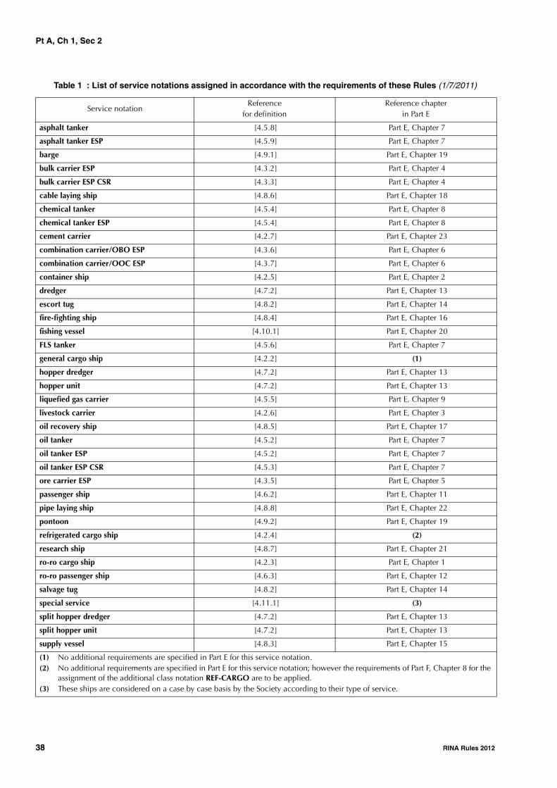
Pt A, Ch 1, Sec 2
38 RINA Rules 2012
Table 1 : List of service notations assigned in accordance with the requirements of these Rules (1/7/2011)
Service notationReference
for definitionReference chapter
in Part E
asphalt tanker [4.5.8] Part E, Chapter 7
asphalt tanker ESP [4.5.9] Part E, Chapter 7
barge [4.9.1] Part E, Chapter 19
bulk carrier ESP [4.3.2] Part E, Chapter 4
bulk carrier ESP CSR [4.3.3] Part E, Chapter 4
cable laying ship [4.8.6] Part E, Chapter 18
chemical tanker [4.5.4] Part E, Chapter 8
chemical tanker ESP [4.5.4] Part E, Chapter 8
cement carrier [4.2.7] Part E, Chapter 23
combination carrier/OBO ESP [4.3.6] Part E, Chapter 6
combination carrier/OOC ESP [4.3.7] Part E, Chapter 6
container ship [4.2.5] Part E, Chapter 2
dredger [4.7.2] Part E, Chapter 13
escort tug [4.8.2] Part E, Chapter 14
fire-fighting ship [4.8.4] Part E, Chapter 16
fishing vessel [4.10.1] Part E, Chapter 20
FLS tanker [4.5.6] Part E, Chapter 7
general cargo ship [4.2.2] (1)
hopper dredger [4.7.2] Part E, Chapter 13
hopper unit [4.7.2] Part E, Chapter 13
liquefied gas carrier [4.5.5] Part E, Chapter 9
livestock carrier [4.2.6] Part E, Chapter 3
oil recovery ship [4.8.5] Part E, Chapter 17
oil tanker [4.5.2] Part E, Chapter 7
oil tanker ESP [4.5.2] Part E, Chapter 7
oil tanker ESP CSR [4.5.3] Part E, Chapter 7
ore carrier ESP [4.3.5] Part E, Chapter 5
passenger ship [4.6.2] Part E, Chapter 11
pipe laying ship [4.8.8] Part E, Chapter 22
pontoon [4.9.2] Part E, Chapter 19
refrigerated cargo ship [4.2.4] (2)
research ship [4.8.7] Part E, Chapter 21
ro-ro cargo ship [4.2.3] Part E, Chapter 1
ro-ro passenger ship [4.6.3] Part E, Chapter 12
salvage tug [4.8.2] Part E, Chapter 14
special service [4.11.1] (3)
split hopper dredger [4.7.2] Part E, Chapter 13
split hopper unit [4.7.2] Part E, Chapter 13
supply vessel [4.8.3] Part E, Chapter 15
(1) No additional requirements are specified in Part E for this service notation.(2) No additional requirements are specified in Part E for this service notation; however the requirements of Part F, Chapter 8 for the
assignment of the additional class notation REF-CARGO are to be applied.(3) These ships are considered on a case by case basis by the Society according to their type of service.

Pt A, Ch 1, Sec 2
RINA Rules 2012 39
Table 2 : List of service notations assigned in accordance with the requirements of separate Rules (1/7/2011)
tanker [4.5.7] Part E, Chapter 10
tug [4.8.2] Part E, Chapter 14
Service notation Separate Rules for reference
HSC (1) (2) (3) Rules for the Classification of High Speed Craft
MODU Rules for the classification of floating offshore units at fixed locations and mobile offshore drilling units
Fixed platform Rules for the Classification of Steel Fixed Offshore Platforms
FPSO: assigned to units intended for the production, storage and off-loading of liquid hydrocarbons FSO : assigned to units intended for the storage and off-loading of liquid hydro-carbonsFSRU: assigned to units intended for off-loading, storage and/or regasifica-tion of liquefied natural gas (LNG) and/or liquefied petroleum gas (LPG)FLNG: assigned to units intended for liquefaction, storage and off-loading of natural gas (LNG)
Rules for the classification of floating offshore units at fixed locations and mobile offshore drilling units
lifting unit Rules for loading and unloading arrangements and for other lifting appliances on board ships
floating dock Rules for the classification of floating docks
submersible Rules for the classification of underwater units
submersible pontoon Rules for the classification of underwater units
submersible pontoon launching Rules for the classification of underwater units
submarine Rules for the classification of underwater units
bathyscaphe Rules for the classification of underwater units
mesoscaphe Rules for the classification of underwater units
(1) The notation is completed by one of the following additional service features, specifying the category of the craft in accordance with the IMO "International Code of Safety for High Speed Craft" :• A for a passenger craft which can be defined according to the Code as category A• B for a passenger craft which can be defined according to the Code as category B• C for a cargo craft which can be defined according to the Code as category C.
(2) The notation may also be completed by one of the following additional service features specifying the type of construction:• MON if the craft is a monohull• CAT if the craft is a catamaran• HYF if the craft is a hydrofoil• ACV if the craft is an air-cushion vehicle• SES if the craft is a surface effect ship• SWATH if the craft is a twin hull small waterplane vehicle.
(3) The notation may be followed by the service notations specified in [4], as applicable; for example by the notation ro-ro passen-ger ship for a passenger craft specially equipped to load trains or wheeled vehicles.
(4) The notation may be completed by the following additional service features:• 12 m SI for boats of 12-metre international rating class• 6 m SI for boats of 6-metre international rating class.
Service notationReference
for definitionReference chapter
in Part E
(1) No additional requirements are specified in Part E for this service notation.(2) No additional requirements are specified in Part E for this service notation; however the requirements of Part F, Chapter 8 for the
assignment of the additional class notation REF-CARGO are to be applied.(3) These ships are considered on a case by case basis by the Society according to their type of service.
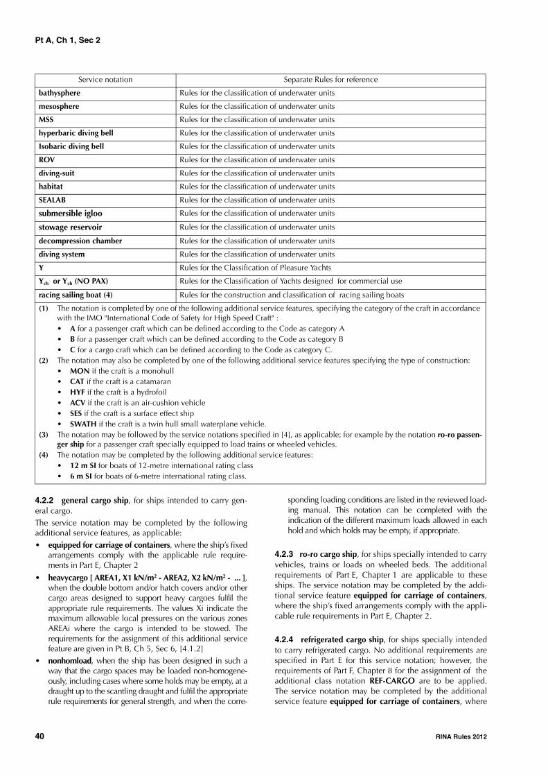
Pt A, Ch 1, Sec 2
40 RINA Rules 2012
4.2.2 general cargo ship, for ships intended to carry gen-eral cargo.The service notation may be completed by the followingadditional service features, as applicable:• equipped for carriage of containers, where the ship’s fixed
arrangements comply with the applicable rule require-ments in Part E, Chapter 2
• heavycargo [ AREA1, X1 kN/m2 - AREA2, X2 kN/m2 - ... ],when the double bottom and/or hatch covers and/or othercargo areas designed to support heavy cargoes fulfil theappropriate rule requirements. The values Xi indicate themaximum allowable local pressures on the various zonesAREAi where the cargo is intended to be stowed. Therequirements for the assignment of this additional servicefeature are given in Pt B, Ch 5, Sec 6, [4.1.2]
• nonhomload, when the ship has been designed in such away that the cargo spaces may be loaded non-homogene-ously, including cases where some holds may be empty, at adraught up to the scantling draught and fulfil the appropriaterule requirements for general strength, and when the corre-
sponding loading conditions are listed in the reviewed load-ing manual. This notation can be completed with theindication of the different maximum loads allowed in eachhold and which holds may be empty, if appropriate.
4.2.3 ro-ro cargo ship, for ships specially intended to carryvehicles, trains or loads on wheeled beds. The additionalrequirements of Part E, Chapter 1 are applicable to theseships. The service notation may be completed by the addi-tional service feature equipped for carriage of containers,where the ship’s fixed arrangements comply with the appli-cable rule requirements in Part E, Chapter 2.
4.2.4 refrigerated cargo ship, for ships specially intendedto carry refrigerated cargo. No additional requirements arespecified in Part E for this service notation; however, therequirements of Part F, Chapter 8 for the assignment of theadditional class notation REF-CARGO are to be applied.The service notation may be completed by the additionalservice feature equipped for carriage of containers, where
bathysphere Rules for the classification of underwater units
mesosphere Rules for the classification of underwater units
MSS Rules for the classification of underwater units
hyperbaric diving bell Rules for the classification of underwater units
Isobaric diving bell Rules for the classification of underwater units
ROV Rules for the classification of underwater units
diving-suit Rules for the classification of underwater units
habitat Rules for the classification of underwater units
SEALAB Rules for the classification of underwater units
submersible igloo Rules for the classification of underwater units
stowage reservoir Rules for the classification of underwater units
decompression chamber Rules for the classification of underwater units
diving system Rules for the classification of underwater units
Y Rules for the Classification of Pleasure Yachts
Ych or Ych (NO PAX) Rules for the Classification of Yachts designed for commercial use
racing sailing boat (4) Rules for the construction and classification of racing sailing boats
Service notation Separate Rules for reference
(1) The notation is completed by one of the following additional service features, specifying the category of the craft in accordance with the IMO "International Code of Safety for High Speed Craft" :• A for a passenger craft which can be defined according to the Code as category A• B for a passenger craft which can be defined according to the Code as category B• C for a cargo craft which can be defined according to the Code as category C.
(2) The notation may also be completed by one of the following additional service features specifying the type of construction:• MON if the craft is a monohull• CAT if the craft is a catamaran• HYF if the craft is a hydrofoil• ACV if the craft is an air-cushion vehicle• SES if the craft is a surface effect ship• SWATH if the craft is a twin hull small waterplane vehicle.
(3) The notation may be followed by the service notations specified in [4], as applicable; for example by the notation ro-ro passen-ger ship for a passenger craft specially equipped to load trains or wheeled vehicles.
(4) The notation may be completed by the following additional service features:• 12 m SI for boats of 12-metre international rating class• 6 m SI for boats of 6-metre international rating class.

Pt A, Ch 1, Sec 2
RINA Rules 2012 41
the ship’s fixed arrangements comply with the applicablerule requirements in Part E, Chapter 2.
4.2.5 container ship, for ships specially intended to carrycontainers in holds or on decks. The additional require-ments of Part E, Chapter 2 are applicable to these ships.
4.2.6 livestock carrier, for ships specially intended tocarry livestock. The additional requirements of Part E,Chapter 3 are applicable to these ships.
4.2.7 (1/7/2006)
cement carrier, for ships specially intended to carry cementin bulk in holds and equipped with fixed arrangements forthat purpose. The additional requirements of Part E,Chapter 23 are applicable to these ships.
The service notation may be completed by the followingadditional service feature, as applicable:
• nonhomload, when the ship has been designed in sucha way that the cargo spaces may be loaded non-homo-geneously, including cases where some holds may beempty, at a draught up to the scantling draught and fulfilthe appropriate Rule requirements for general strength,and when the corresponding loading conditions arelisted in the reviewed loading manual. This notation canbe completed with the indication of the different maxi-mum loads allowed in each hold and which holds maybe empty, if appropriate.
4.3 Bulk, ore and combination carriers
4.3.1 (1/4/2006)
The service notations related to self-propelled ships (seeNote 1) intended for the carriage of dry cargo in bulk arelisted in [4.3.2] to [4.3.7] below.
The service notations described in this item are always com-pleted by the additional service feature ESP, which meansthat these ships are submitted to the Enhanced Survey Pro-gram as laid down in Ch 4, Sec 2.
Example: ore carrier ESP
Note 1: Self-propelled ships are ships with mechanical means ofpropulsion not requiring assistance from another ship during nor-mal operation.
The service notation bulk carrier is completed by the addi-tional service feature CSR for bulk carriers built in accord-ance with the "Common Structural Rules for Bulk Carriers"(i.e. single side skin and double side skin bulk carriers withunrestricted worldwide navigation, having length L of 90 mor greater, contracted for construction on or after 1 April2006).
Example: bulk carrier ESP CSR
4.3.2 (1/4/2006)
bulk carrier ESP, for self-propelled ships which are con-structed generally with single deck, double bottom, hopperside tanks and topside tanks and with single or double sideskin construction in cargo length area and intended prima-rily to carry dry cargoes in bulk (see Note 1). Typical mid-ship sections are given in Fig 1. However, other midshipsection arrangements may be accepted, if deemed equiva-lent by the Society.
The additional requirements of Part E, Chapter 4 are appli-cable to these ships.Note 1: For bulk carriers with hybrid cargo hold arrangements, i.e.with some cargo holds of single side skin and others of double sideskin, the requirements of Ch 4, Sec 2 are to apply to cargo holds ofsingle side skin and those of Ch 4, Sec 9 to cargo holds of doubleside skin.
Figure 1 : Typical midship sections of shipswith service notation bulk carrier ESP
Left: Single side skin construction
Right: Double side skin construction
4.3.3 (1/4/2006)bulk carrier ESP CSR, for self-propelled ships which areconstructed generally with single deck, double bottom,hopper side tanks and topside tanks and with single or dou-ble side skin construction in the cargo length area andintended primarily to carry dry cargoes in bulk (see Note 1),with unrestricted worldwide navigation, having length L of90 m or greater, contracted for construction on or after 1April 2006. Typical midship sections are given in Fig 1.
The additional requirements of Part E, Chapter 4 are appli-cable to these ships with the limitations indicated therein.Note 1: For bulk carriers with hybrid cargo hold arrangements, i.e.with some cargo holds of single side skin and others of double sideskin, the requirements of Ch 4, Sec 2 are to apply to cargo holds ofsingle side skin and those of Ch 4, Sec 9 to cargo holds of doubleside skin.
4.3.4 (1/4/2006)The service notations in [4.3.2] and [4.3.3] may be com-pleted by the following additional service features, as appli-cable:
• heavycargo [HOLDi, Xi kN/m2, ρi kN/m3 - HATCHi, Y ikN/m2], when the ship's structure designed to supportheavy cargoes fulfils the appropriate Rule requirements.
The values Xi and Yi indicate, respectively, the maxi-mum allowable local pressures on the inner bottoms ofthe various HOLDi and on the hatch covers HATCHiwhere the cargo is intended to be stowed and ρi is themaximum density of the bulk cargo allowable for car-riage in the relevant HOLDi. The requirements for theassignment of this additional service feature are given inPt E, Ch 4, Sec 3, [4.8];
• nonhomload, when the ship has been designed in sucha way that the cargo spaces may be loaded non-homo-geneously, including cases where some holds may beempty, at a draught up to the scantling draught and fulfilthe appropriate Rule requirements for general strength,and when the corresponding loading conditions arelisted in the reviewed loading manual. This notation can

Pt A, Ch 1, Sec 2
42 RINA Rules 2012
be completed with the indication of the different maxi-mum loads allowed in each hold and which holds maybe empty, if appropriate.
• double skin, when the ship is constructed in accordancewith the definition given in Ch 2, Sec 2, [2.2.19].
4.3.5 (1/1/2005)The notation ore carrier ESP, or equivalent, is to beassigned to self-propelled ships which are constructed gen-erally with single deck, two longitudinal bulkheads and adouble bottom throughout the cargo length area andintended primarily to carry ore cargoes in the centre holdsonly. Typical midship sections are given in Fig 2. However,other midship section arrangements may be accepted, ifdeemed equivalent by the Society.
The additional requirements of Part E, Chapter 5 are appli-cable to these ships.
Figure 2 : Typical midship section of shipwith service notation ore carrier ESP (1/1/2005)
4.3.6 (1/1/2012)
combination carrier/OBO ESP for self-propelled shipsintended to carry both oil and dry cargoes in bulk; thesecargoes are not carried simultaneously, with the exceptionof oily mixture retained in slop tanks. This notation isassigned to ships which are constructed generally with sin-gle deck, double bottom, hopper side tanks and topsidetanks and with single or double side skin construction in thecargo length area, and intended primarily to carry oil or drycargoes, including ore, in bulk. Typical midship sections aregiven in Fig 3. The additional requirements of Part E,Chapter 6 are applicable to these ships.Note 1: Combination carriers/OBO that do not comply with MAR-POL I/19 may be subject to international and/or national regula-tions requiring phase out.
Figure 3 : Typical midship section of shipwith service notation combination carrier/OBO
ESP (1/1/2005)
Left: Single side skin construction
Right: Double side skin construction
4.3.7 (1/1/2012)
combination carrier/OOC ESP, for self-propelled shipsintended to carry both oil and dry cargoes in bulk; thesecargoes are not carried simultaneously, with the exceptionof oily mixture retained in slop tanks. This notation isassigned to ships which are constructed generally with sin-gle deck, two longitudinal bulkheads and a double bottomthroughout the cargo length area, and intended primarily tocarry ore cargoes in the centre holds and oil cargoes in thecentre holds and wing tanks. Typical midship sections aregiven in Fig 4. The additional requirements of Part E,Chapter 6 are applicable to these ships.
Note 1: Combination carriers/OOC that do not comply with MAR-POL I/19 may be subject to international and/or national regula-tions requiring phase out.
4.4 Additional service features and corre-sponding design loading conditions for bulk carriers
4.4.1 (1/4/2006)
The requirements of item [4.4] are applicable to bulk carri-ers as defined in [4.3.2], having length as defined in Pt B,Ch 1, Sec 2, [3.1] of 150 m or greater and contracted fornew construction on or after 1 July 2003.
For bulk carriers ESP CSR, as defined in [4.3.3], havinglength as defined in Pt B, Ch 1, Sec 2, [3.1] of 150 m orgreater and contracted for new construction on or after 1April 2006, the requirements of the "Common StructuralRules for Bulk Carriers", Ch 1, Sec 1, [3] apply instead.
Figure 4 : Typical midship sections of ships with service notation combination carrier/OOC ESP (1/1/2005)

Pt A, Ch 1, Sec 2
RINA Rules 2012 43
4.4.2 (1/7/2003)
The loading conditions listed in Pt E, Ch 4, Sec 3, [4.1],Pt E, Ch 4, Sec 3, [4.2] and Pt E, Ch 4, Sec 3, [4.3] are to beused for the checking of rule criteria regarding longitudinalstrength (as required by Pt B, Ch 6, Sec 2, [3] and Pt E,Ch 4, Sec 3, [5]), local strength, capacity and arrangementof ballast tanks and stability. The loading conditions listedin Pt E, Ch 4, Sec 3, [4.8]) are to be used for the checking ofrule criteria regarding local strength.
4.4.3 (1/7/2003)
For the purpose of applying the conditions for the assign-ment of the harmonised notations, maximum draught is tobe taken as moulded summer load line draught.
4.4.4 (1/7/2003)
Bulk carriers are to be assigned one of the following addi-tional service features.
a) BC-A: for bulk carriers designed to carry dry bulk car-goes of cargo density 1,0 t/m3 and greater with specifiedholds empty at maximum draught in addition to BC-Bconditions.
b) BC-B: for bulk carriers designed to carry dry bulk car-goes of cargo density of 1,0 t/m3 and greater with allcargo holds loaded in addition to BC-C conditions.
c) BC-C: for bulk carriers designed to carry dry bulk car-goes of cargo density less than 1,0 t/m3.
The following additional service features are to be providedgiving further detailed description of limitations to beobserved during operation as a consequence of the designloading condition applied during the design in the follow-ing cases:
• maximum cargo density (in t/m3) for notations BC-A andBC-B, if the maximum cargo density is less than 3.0 t/m3
• no MP for all notations, when the vessel has not beendesigned for loading and unloading in multiple ports inaccordance with the conditions specified in Pt E, Ch 4,Sec 3, [4.5.4]
• allowed combination of specified empty holds for nota-tion BC-A.
Note 1: The requirements of this item [4.4] are not intended to pre-vent any other loading conditions being included in the loadingmanual, for which calculations are to be submitted as required; norare they intended to replace in any way the required loading man-ual/instrument.
Note 2: A bulk carrier in actual operation may be loaded differentlyfrom the design loading conditions specified in the loading man-ual, provided limitations for longitudinal and local strength asdefined in the loading manual and loading instrument on boardand applicable stability requirements are not exceeded.
4.5 Ships carrying liquid cargo in bulk
4.5.1 (1/7/2011)
The service notations related to self-propelled ships (seeNote 1) intended for the carriage of liquid cargo in bulk arelisted in [4.5.2] to [4.5.10] below.
Note 1: Self-propelled ships are ships with mechanical means ofpropulsion not requiring assistance from another ship during nor-mal operation.
4.5.2 (1/7/2011)oil tanker, for self-propelled ships which are intended pri-marily to carry in bulk crude oil or other oil products havingany flash point, liquid at atmospheric pressure and ambienttemperature (or thus maintained by heating).
This notation is to be assigned to tankers of both single anddouble hull construction, as well as tankers with alternativestructural arrangements, provided they are deemed equiva-lent by the Society.
For oil tankers with integral cargo tanks, the service nota-tion oil tanker is always completed by the additional serv-ice feature ESP (i.e. oil tanker ESP), which means that theseships are submitted to the Enhanced Survey Program as laiddown in Ch 4, Sec 3 or Ch 4, Sec 4, as applicable.Note 1: Oil tankers that do not comply with MARPOL I/19 may besubject to international and/or national regulations requiring phaseout under MARPOL I/20 and/or MARPOL I/21. (This Note 1 appliesfrom 1/1/2012).
The service notation may be completed by the followingadditional service features, as applicable:• flash point > 60°C, where the ship is intended to carry
only such type of products, under certain conditions• double hull, when the ship is constructed in accordance
with the definition given in Ch 2, Sec 2, [2.2.16]• double hull (heavy grades), when the ship is con-
structed in accordance with the definition given in Ch 2,Sec 2, [2.2.18]
• double hull (independent tanks), when the ship is con-structed in accordance with the definition given in Ch 2,Sec 2, [2.2.17]
• product, where the ship is intended to carry only prod-ucts other than crude oil.
The additional requirements of Part E, Chapter 7 are appli-cable to these ships.
4.5.3 (1/7/2011)The service notation oil tanker ESP is always completed bythe additional service feature CSR for oil tankers built inaccordance with the "Common Structural Rules for DoubleHull Oil Tankers" (i.e. double hull oil tankers having lengthL of 150 m or greater, contracted for construction on or after1 April 2006).
Example: oil tanker ESP CSR
The additional requirements of Part E, Chapter 7 are appli-cable to these ships with the limitations indicated therein.
4.5.4 (1/7/2011)chemical tanker, for self-propelled ships which intendedprimarily to carry in bulk chemical products presentingsafety and/or pollution hazards. This notation is to beassigned to tankers of both single and double hull construc-tion, as well as tankers with alternative structural arrange-ments, provided they are deemed equivalent by the Society.
For chemical tankers with integral cargo tanks, the servicenotation chemical tanker is always completed by the addi-tional service feature ESP (i.e. chemical tanker ESP), whichmeans that these ships are submitted to the Enhanced Sur-vey Program as laid down in Ch 4, Sec 5.
The additional requirements of Part E, Chapter 8 are appli-cable to these ships.

Pt A, Ch 1, Sec 2
44 RINA Rules 2012
The list of products the ship is allowed to carry is attachedto the Certificate of Classification or the Certificate of Fit-ness, where issued by the Society, including, where neces-sary, the maximum allowable specific gravity and/ortemperature.
The service notation may be completed by the additionalservice feature IMO 1, IMO 2 or IMO 3, when the shipcomplies with the requirements for the assignment of type1, type 2 or type 3, respectively, in accordance with Chap-ter 2 of the IBC Code.
4.5.5 liquefied gas carrier, for ships specially intended tocarry liquefied gases or other substances listed in Pt E, Ch 9,Sec 1 of the Rules. The additional requirements of Part E,Chapter 9 are applicable to these ships.
The list of products the ship is allowed to carry is attachedto the Certificate of Classification or the Certificate of Fit-ness, where issued by the Society, including, where neces-sary, the conditions of transportation (pressure, temperature,filling limits).
4.5.6 (1/4/2006)
FLS tanker, for ships specially intended to carry in bulkflammable liquid products other than those covered by theservice notations oil tanker ESP, oil tanker ESP CSR, chemi-cal tanker ESP or liquefied gas carrier
The list of products the ship is allowed to carry may beattached to the Certificate of Classification, including,where necessary, the maximum allowable specific gravityand/or temperature.
The service notation may be completed by the additionalservice feature flash point > 60°C, where the ship isintended to carry only such type of products, under certainconditions.
For ships intended to carry only one type of cargo, the serv-ice notation may be completed by the additional servicefeature indicating the type of product carried, e.g. FLStanker-acetone.
The additional requirements of Part E, Chapter 7 are appli-cable to these ships.
4.5.7 tanker, for ships intended to carry non-flammableliquid cargoes in bulk other than those covered by the serv-ice notations in [4.5.2] to [4.5.6] above, such as wine orwater.
The list of cargoes the ship is allowed to carry may beattached to the Certificate of Classification.
For ships intended to carry only one type of cargo, the serv-ice notation may be completed by the additional servicefeature indicating the type of product carried, e.g. tanker-potable water.
The additional requirements of Part E, Chapter 10 are appli-cable to these ships.
4.5.8 (1/7/2011)
asphalt tanker, for self-propelled ships which are con-structed with independent, non-integral cargo tanks,intended to only carry such type of products, under certainconditions. The maximum cargo temperature will be indi-cated on the Certificate of Classification.
The additional requirements of Part E, Chapter 7 are appli-cable to these ships.
4.5.9 (1/7/2011)
For asphalt tankers intended to only carry such type of prod-ucts under certain conditions, but with integral cargo tanks,the service notation asphalt tanker is always completed bythe additional service feature ESP (i.e. asphalt tanker ESP),which means that these ships are submitted to the EnhancedSurvey Program as laid down in Ch 4, Sec 3. The maximumcargo temperature will be indicated on the Certificate ofClassification.
The additional requirements of Part E, Chapter 7 are appli-cable to these ships.
4.5.10 Refer also to [4.3.6] and [4.3.7] for combinationcarrier intended to carry alternatively oil products and drycargo in bulk in cargo holds/tanks.
4.6 Ships carrying passengers
4.6.1 The service notations related to ships speciallyintended for the carriage of passengers are listed in [4.6.2]to [4.6.3] below.
4.6.2 passenger ship, for ships intended to carry more than12 passengers. The additional requirements of Part E,Chapter 11 are applicable to these ships.
The service notation may be completed by the additionalservice feature < 36 passengers, where the ship is intendedto carry only such a limited number of passengers.
4.6.3 ro-ro passenger ship, for ships intended to carrymore than 12 passengers and specially equipped to loadtrains or wheeled vehicles. The additional requirements ofPart E, Chapter 12 are applicable to these ships.
The service notation may be completed by the additionalservice feature < 36 passengers, where the ship is intendedto carry only such a limited number of passengers.
4.7 Ships for dredging activities
4.7.1 The service notations related to ships speciallyintended for dredging activities are listed in [4.7.2]. Theadditional requirements of Part E, Chapter 13 are applicableto these ships.
4.7.2 The following notations are provided:
a) dredger, for ships specially equipped only for dredgingactivities (excluding carrying dredged material)
b) hopper dredger, for ships specially equipped for dredg-ing activities and carrying spoils or dredged material
c) hopper unit, for ships specially equipped for carryingspoils or dredged material
d) split hopper unit, for ships specially equipped for carry-ing spoils or dredged material and which open longitu-dinally, around hinges
e) split hopper dredger, for ships specially equipped fordredging and for carrying spoils or dredged material andwhich open longitudinally, around hinges.

Pt A, Ch 1, Sec 2
RINA Rules 2012 45
4.7.3 These ships which are likely to operate at sea withinspecific limits may, under certain conditions, be granted anoperating area notation. For the definition of operating areanotation, reference should be made to [5.3].
4.8 Working ships
4.8.1 The service notations related to ships speciallyintended for different working services are listed in [4.8.2]to [4.8.6] below.
4.8.2 (1/7/2010)
The service notations for ships intended to tow and/or pushother ships or units are:
a) tug, for ships specially equipped for towing and/orpushing
b) salvage tug, for ships specially equipped for towingand/or pushing having specific equipment for salvage
c) escort tug, for ships specially equipped for towingand/or pushing having specific equipment for escortingships or units during navigation.
The additional requirements of Part E, Chapter 14 are appli-cable to these ships.
These service notations may be completed by the additionalservice features:
• barge combined, when units are designed to be con-nected with barges and comply with the relevantrequirements of Pt E, Ch 14, Sec 3. The barges to whichthe tug can be connected are specified in an annex tothe Certificate of Classification.
• rescue, when units are specially equipped for rescue ofshipwrecked persons and for their accommodation.
The maximum number of shipwrecked persons for whichthe unit is designed as well as the ship operational area,where Pt E, Ch 14, Sec 2, [2.10.3] applies, are recorded inthe Certificate of Classification of the ship.
The relevant arrangements and equipment are recorded inthe ship's status.
4.8.3 (1/7/2011)
The service notation supply vessel is assigned to ships spe-cially intended for the carriage and/or storage of specialmaterial and equipment and/or which are used to providefacilities and assistance for the performance of specifiedactivities, such as offshore and underwater activities.
The service notation is to be completed by the additionalservice feature oil product, when the ship is also speciallyintended to carry oil products having any flash point.
The service notation is to be completed by the additionalservice feature chemical product, when the ship is also spe-cially intended to carry chemical products having any flashpoint.
The service notation is to be completed by the additionalservice feature standby, when the ship is also speciallyintended to perform rescue and standby services for off-shore installations (e.g. supply vessel - standby).
The service notation is completed by the additional servicefeature rescue, when the ship is specially equipped for res-cue of shipwrecked persons and for their accommodation.
The service notation is completed by the additional servicefeatures:
• anchor handling, when the ship visibility from thebridge and equipment are specially designed for anchorhandling operation; or
• anchor handling stab, when the ship is speciallydesigned and equipped for anchor handling operationand also fulfils specific stability requirements related tothis service.
The additional requirements of Part E, Chapter 15 are appli-cable to these ships.
4.8.4 The service notation fire-fighting ship is assigned toships specially intended and equipped for fighting fire. Theadditional requirements of Part E, Chapter 16 are applicableto these ships.
The service notation may be completed by the followingadditional service features, as applicable:
• 1 or 2 or 3, when the ship complies with the applicablerequirements of Pt E, Ch 16, Sec 3
• E when the characteristics of the fire-fighting system arenot those required for the assignment of the additionalservice features 1, 2 or 3, and when the system is spe-cially considered by the Society
• water-spraying when the ship is fitted with a self-protec-tion water-spraying system complying with the applica-ble requirements of Pt E, Ch 16, Sec 4, [3].
4.8.5 (1/1/2012)
The service notation oil recovery ship is assigned to shipsspecially equipped with fixed installations and/or mobileequipment for the removal of oil from the sea surface and itsretention on board, carriage and subsequent unloading. Theadditional requirements of Part E, Chapter 17 are applicableto these ships.
The service notation may be completed by the additionalservice feature flash point > 60°C, where the ship collectsonly oil with flash point exceeding 60°C.
4.8.6 The service notation cable laying ship is assigned toships specially equipped for the carriage and/or laying,hauling and repair of submarine cables. The additionalrequirements of Part E, Chapter 18 are applicable to theseships.
4.8.7 (1/7/2004)
The service notation research ship is assigned to ships spe-cially intended for scientific or technological research. Theadditional requirements of Part E, Chapter 21 are applicableto these ships.
4.8.8 (1/1/2005)
The service notation pipe laying ship is assigned to shipsspecially equipped for the carriage and/or laying, haulingand repair of submarine pipes. The additional requirementsof Part E, Chapter 22 are applicable to these ships.

Pt A, Ch 1, Sec 2
46 RINA Rules 2012
4.9 Non-propelled and assisted propulsion units, sailing ships
4.9.1 Barge
The service notation barge is assigned to non-propelledunits intended to carry (dry or liquid) cargo inside holds ortanks. The type of cargo may be considered adding an addi-tional service feature, e.g. barge - oil, barge - general cargo.The additional requirements of Part E, Chapter 19 are appli-cable to these ships.
This service notation may be completed by the additionalservice feature tug combined when units are designed to beconnected with tugs, and comply with the relevant require-ments of Pt E, Ch 14, Sec 3. The tugs to which the bargecan be connected are specified in an annex to the Certifi-cate of Classification.
4.9.2 Pontoon
The service notation pontoon is assigned to non-propelledunits intended to carry cargo and/or equipment on deckonly. When a crane is permanently fitted on board, thecrane is to be certified and the service notation pontoon -crane is granted. The additional requirements of Part E,Chapter 19 are applicable to these ships.
4.9.3 Other units
Any non-propelled units other than those covered by theservice notations listed above will be assigned the addi-tional service feature no propulsion, to be added to theirown service notation, e.g. dredger - no propulsion.
4.9.4 Assisted propulsion units
Any units having a propulsion system not enabling them toproceed at a speed greater than 7 knots, used for short tran-sit voyages, will be assigned the additional service featureassisted propulsion to be added to their own service nota-tion, e.g. dredger - assisted propulsion.
4.9.5 Sailing ships (1/7/2009)
The additional service feature sailing ships is assigned toships having no means of propulsion other than sails. Theseships are to comply with the requirements of the "Rules formasting and rigging of sailing ships", issued separately bythe Society.
4.9.6 Engine assisted sailing ship (1/7/2009)
The additional service feature engine assisted sailing ship isassigned to ships having sails as main means of propulsionwhich may also be propelled by internal combustionengines enabling the navigation of the ship without sails ifnecessary.
4.9.7 Engine powered sailing ship (1/7/2009)
The additional service feature engine powered sailing shipis assigned to ships propelled primarily by internal combus-tion engines of power adequate to maintain a speed of atleast 7 knots (at continuous service rating, when the ship isfully loaded, in smooth water) when not under sail, butwhich are provided with sails as an emergency means ofpropulsion.
4.10 Fishing vessels
4.10.1 The service notation fishing vessel is assigned toships specially equipped for catching and storing fish orother living resources of the sea. The additional require-ments of Part E, Chapter 20 are applicable to these ships.
Note 1: Units solely dedicated to service in a fishing flotilla bymeans of cold storage and/or transformation of fish are not coveredby the service notation fishing vessel. They will be considered withthe service notation special service.
4.11 Miscellaneous units
4.11.1 The service notation special service is assigned toships which, due to the peculiar characteristics of theiractivity, are not covered by any of the notations mentionedabove. The classification requirements of such units areconsidered by the Society on a case by case basis.
This service notation may apply, for instance, to shipsengaged in research, expeditions and survey, ships for train-ing of marine personnel, whale and fish factory ships notengaged in catching, ships processing other living resourcesof the sea, and other ships with design features and modesof operation which may be referred to the same group ofships.
An additional service feature may be specified after thenotation (e.g. special service - training, special service -ship lift, special service - fish factory) to identify the partic-ular service in which the ship is intended to trade. Thescope and criteria of classification of such units are indi-cated in an annex to the Certificate of Classification.
5 Navigation and operating area nota-tions
5.1 Navigation notations
5.1.1 Every classed ship is to be assigned one navigationnotation as listed in [5.2].
5.1.2 The assignment of a navigation notation, includingthe reduction of scantlings or specific arrangements forrestricted navigation notations, is subject to compliancewith the requirements laid down in Part B, Part C, Part Dand Part E of the Rules.
5.1.3 The assignment of a navigation notation does notabsolve the Interested Party from compliance with any inter-national and national regulations established by the Admin-istrations for a ship operating in national waters, or aspecific area, or a navigation zone. Neither does it waivethe requiremnts in Sec 1, [3.3.1].
5.2 List of navigation notations
5.2.1 The navigation notation unrestricted navigation isassigned to a ship intended to operate in any area and anyperiod of the year.

Pt A, Ch 1, Sec 2
RINA Rules 2012 47
5.2.2 The navigation notation summer zone is assigned toships intended to operate only within the geographical lim-its as defined in ILLC 1966 for the Summer zones.
5.2.3 The navigation notation tropical zone is assigned toships intended to operate only within the geographical lim-its as defined in ILLC 1966 for the Tropical zones.
5.2.4 The navigation notation coastal area is assigned toships intended to operate only within 20 nautical milesfrom the shore and with a maximum sailing time of sixhours from a port of refuge or safe sheltered anchorage.
5.2.5 The navigation notation sheltered area is assigned toships intended to operate in sheltered waters , i.e. harbours,estuaries, roadsteads, bays, lagoons and generally calmstretches of water and when the wind force does not exceed6 Beaufort scale.
5.2.6 (1/7/2009)
The navigation notations defined in these items [5.2.1] to[5.2.5] are those considered as "normal". Where particularcases of navigation are to be assigned which are notincluded among those so defined, the navigation notationspecial is assigned, followed by specified restrictions (suchas the designation of the geographical area, distance fromthe shore and/or the most unfavourable sea conditions con-sidered).
5.2.7 (1/7/2009)
The Society may assign navigation notations provided bythe regulations of the flag Administration, which may be dif-ferent from those defined in [5.2.1] to [5.2.6].
5.3 Operating area notations
5.3.1 The operating area notation expresses the specifiedarea where some service units are likely to operate at seawithin specific restrictions which are different from normalnavigation conditions.
The operating area notation is, in principle, solely grantedto working units, such as dredgers and crane pontoons.
This operating area notation is indicated after the navigationnotation.
Example: unrestricted navigation - “operating area nota-tion”
5.3.2 The following operating area notations may beassigned:
a) notation specified operating area, where the specificoperating conditions which have been considered bythe Society are described in an annex to the Certificateof Classification (i.e. distance from shore or from port ofrefuge, weather or sea conditions)
b) notation operation service within ’x’ miles from shore,where the operating service is limited to a certain dis-tance from the shore.
6 Additional class notations
6.1 General
6.1.1 An additional class notation expresses the classifica-tion of additional equipment or specific arrangement,which has been requested by the Interested Party.
6.1.2 The assignment of such an additional class notationis subject to the compliance with additional rule require-ments, which are detailed in Part F of the Rules.
6.1.3 Some additional class notations, due to the impor-tance of relevant equipment or arrangements, are assigneda construction mark, according to the principles given in[3.1.2]. This is indicated in the definition of the relevantadditional class notations.
6.1.4 The different additional class notations which maybe assigned to a ship are listed in [6.2] to [6.14], accordingto the category to which they belong. These additional classnotations are also listed in alphabetical order in Tab 3.
6.2 System of Trace and Analysis of Records (STAR)
6.2.1 General (1/7/2008)
STAR is a System of Trace and Analysis of Records integrat-ing rational analysis with data and records from ship-in-service concerning planned inspection and ship mainte-nance.
The requirements for the assignment of these notations aregiven in Part F, Chapter 1.
6.2.2 STAR-HULL (1/10/2000)
The additional class notation STAR-HULL is assigned toships on which an Inspection and Maintenance Plan (IMP)for the hull is implemented.
The notation may be completed by the suffix NB when astructural tridimensional analysis has been performed forthe hull structures, as defined in Pt B, Ch 7, App 1 or Pt B,Ch 7, App 2 or Pt B, Ch 7, App 3, as applicable, at the newbuilding stage. The suffix NB is removed when the shipenters the STAR-HULL survey programme through theimplementation of the Inspection and Maintenance Plan(IMP).
6.2.3 STAR-MACH (1/7/2003)
The additional class notation STAR-MACH is assigned toships on which an Inspection and Maintenance Plan (IMP)for the machinery is implemented. This plan is based on arisk analysis review of the installation.
6.2.4 STAR notation (STAR)
When ships are granted both STAR-HULL and STAR-MACH, the two separate notations are superseded by thecumulative additional class notation STAR.

Pt A, Ch 1, Sec 2
48 RINA Rules 2012
6.3 Availability of machinery (AVM)
6.3.1 GeneralThe notations dealt with under this heading are relevant tosystems and/or arrangements enabling the ship to carry onlimited operations when single failure affects propulsion orauxiliary machinery or when an event such as fire or flood-ing involving machinery spaces affects the availability of themachinery.
In compliance with [6.1.3], these notations are assigned aconstruction mark, as defined in [3].
The requirements for the assignment of these notations aregiven in Part F, Chapter 2.
6.3.2 AVM-APS (Alternative propulsion system) (1/7/2008)
The additional class notation AVM-APS or AVM-APS-NS areassigned to ships which are fitted with systems and/orarrangements enabling them to maintain operating condi-tions with some limitations in speed, range and comfort, inthe case of any single failure of items relative to the propul-sion.
When the auxiliary propulsion system is designed for use inconditions other than an emergency, the additional classnotation AVM-APS-NS is assigned.
6.3.3 AVM-IAPS (Independent alternative propulsion system) (1/7/2008)
The additional class notation AVM-IAPS is assigned to shipswhich are fitted with an independent propulsion systemenabling them to maintain operating conditions with somelimitations in power, speed, range and comfort, in the caseof any single failure of items relative to the propulsion.
6.3.4 AVM-DPS (Duplicated propulsion system) (1/7/2008)
The additional class notation AVM-DPS or AVM-DPS-NSare assigned to ships which are fitted with a duplicated pro-pulsion system enabling them to maintain operating condi-tions with some limitations in power (but 50% of the mainpower is to be maintained), speed, range and comfort, inthe case of any single failure of items relative to the propul-sion.
When the duplicated propulsion system is designed for usein conditions other than an emergency, the additional classnotation AVM-DPS-NS is assigned.
6.3.5 AVM-IPS (Independent propulsion system) (1/7/2008)
The additional class notation AVM-IPS is assigned to shipswhich are fitted with an independent propulsion systemenabling them to maintain operating conditions with somelimitations in power (but 50% of the main power is to bemaintained), speed, range and comfort, in the case of anysingle failure of items relative to the propulsion.
6.4 Automated machinery systems (AUT)
6.4.1 GeneralThe notations dealt with under this heading are relevant toautomated machinery systems installed on board ships.
In compliance with [6.1.3], these notations are assigned aconstruction mark, as defined in [3].
The requirements for the assignment of these notations aregiven in Part F, Chapter 3.
6.4.2 Unattended machinery space (AUT-UMS)
The additional class notation AUT-UMS is assigned to shipswhich are fitted with automated installations enablingmachinery spaces to remain periodically unattended in allsailing conditions including manoeuvring.
6.4.3 Centralised control station (AUT-CCS)
The additional class notation AUT-CCS is assigned to shipswhich are fitted with machinery installations operated andmonitored from a centralised control station.
6.4.4 Automated operation in port (AUT-PORT)
The additional class notation AUT-PORT is assigned to shipswhich are fitted with automated installations enabling theship’s operation in port or at anchor without personnel spe-cially assigned for the watch-keeping of the machinery inservice.
6.5 Integrated ship systems (SYS)
6.5.1 General
The notations dealt with under this heading are relevant tooperation of integrated systems regarding navigation,machinery, communication and specific cargo, as applica-ble.
In compliance with [6.1.3], these notations are assigned aconstruction mark, as defined in [3].
The requirements for the assignment of these notations aregiven in Part F, Chapter 4.
6.5.2 Centralised navigation equipment (SYS-NEQ)
The additional class notation SYS-NEQ is assigned to shipswhich are fitted with a centralised navigation control systemso laid out and arranged that it enables normal navigationand manoeuvring operation of the ship by two persons incooperation.
The additional class notation SYS-NEQ-1 is assigned when,in addition to the above, the installation is so arranged thatthe navigation and manoeuvring of the ship can be oper-ated under normal conditions by one person, for periodicalone man watch. This notation includes specific require-ments for prevention of accidents caused by the operator’sunfitness.
6.5.3 Integrated bridge system (SYS-IBS)
The additional class notation SYS-IBS is assigned to shipswhich are fitted with an integrated bridge system whichallows simplified and centralised bridge operation of allmain functions of navigation manoeuvring and communi-cation, as well as monitoring from bridge of other functionsrelated to specific cargoes and pollution ; for passengerships, heating, ventilation and air conditioning are alsoincluded in the monitored functions.
Pt A, Ch 1, Sec 2
RINA Rules 2012 49
6.5.4 Communication system (SYS-COM) (1/7/2009)
The additional class notation SYS-COM is assigned to shipswhich are fitted with a local area network including thealarm, monitoring and control systems and computers usedfor management operations and external communicationdevices for reporting ashore navigation, maintenance andoperational information.
6.6 Monitoring equipment (MON)
6.6.1 General
The notations dealt with under this heading are relevant tohull and tailshaft monitoring equipment installed on boardships.
The requirements for the assignment of these notations aregiven in Part F, Chapter 5.
6.6.2 Hull stress monitoring (MON-HULL)
The additional class notation MON-HULL is assigned toships which are fitted with equipment continuously moni-toring ship’s dynamic loads through measurements ofmotions in waves and stresses/deformations in the hullstructure.
6.6.3 Tailshaft monitoring system (MON-SHAFT)
The additional class notation MON-SHAFT is assigned toships which are fitted with a temperature monitoring systemfor the tailshaft sterntube bearings. The assignment of thisnotation allows the ship to be granted a reduced scope forcomplete tailshaft surveys, see Ch 2, Sec 2, [5.5.4].
6.7 Comfort on board ships (COMF)
6.7.1 General
The notations dealt with under this heading are relevant tothe assessment of comfort on board ships with regard to thelevel of noise, vibration and/or air temperature/humidity.
The parameters which are taken into consideration for theevaluation of the comfort such as the level of noise, thelevel of vibration and the air temperature and/or humiditywill be indicated in the Certificate of Classification.
These parameters are only verified once for all when theship is classed.
The requirements for the assignment of these notations aregiven in Part F, Chapter 6.
6.7.2 Comfort with regard to noise (COMF-NOISE) (1/7/2007)
The additional class notation COMF-NOISE is assigned toships satisfying levels of noise defined in Pt F, Ch 6, Sec 1.The assessment of noise levels is only carried out throughdesign review and sea trials.
The notation is completed by a letter A, B or C which repre-sents the merit level achieved for the assignment of thenotation, the merit A corresponding to the lowest level of
acceptable noise. The notation COMF-NOISE is onlyassigned if at least the merit level C is reached.
When the merit levels achieved for the passenger spaces (ifany) and the crew spaces are different, the notation is com-pleted by the suffix:
• PAX, for passenger spaces, and
• CREW, for crew spaces.
6.7.3 Comfort with regard to vibration (COMF-VIB) (1/7/2007)
The additional class notation COMF-VIB is assigned toships satisfying levels of vibration defined in Pt F, Ch 6,Sec 2. The assessment of vibration levels is only carried outthrough design review and sea trials.
The notation is completed by a letter A, B or C, which rep-resents the merit level achieved for the assignment of thenotation, merit A corresponding to the lowest level of vibra-tion. The notation COMF-VIB is only assigned if at leastmerit level C is reached.
When the merit levels achieved for the passenger spaces (ifany) and the crew spaces are different, the notation is com-pleted by the suffix:
• PAX, for passenger spaces, and
• CREW, for crew spaces.
6.7.4 Comfort with regard to air temperature/humidity (COMF-AIR)
The additional class notation COMF-AIR is assigned toships fitted with a combined heating-ventilation-air condi-tioning system (HVAC) satisfying levels of air temperatureand humidity defined in Pt F, Ch 6, Sec 3. The assessmentof air temperature/humidity levels is only carried outthrough design review and sea trials in Winter and Summerconditions.
The notation may be completed by one of the letters W or Swhen the HVAC system has been satisfactorily tested onlyin Winter or in Summer conditions respectively.
6.8 Pollution prevention
6.8.1 General
The notations dealt with under this heading are assigned toships fitted with equipment and arrangements enablingthem to reduce the pollution of the sea and/or air caused byrelease of solid waste and liquid and/or gaseous effluents.
The requirements for the assignment of these notations aregiven in Part F, Chapter 7.
6.8.2 Sea pollution prevention (CLEAN-SEA) (1/7/2006)
The additional class notation CLEAN-SEA is assigned toships provided with construction and procedural means toprevent pollution of the sea.

Pt A, Ch 1, Sec 2
50 RINA Rules 2012
This is achieved by compliance with the applicable require-ments of Annex I, Annex II, Annex III, Annex IV and AnnexV of MARPOL Convention, relevant to ship’s liquid andsolid releases, as well as additional requirements related toprevention of sea pollution as follows:
• prevention of accidental pollution by means of locationof fuel and lube oil tanks above the double bottom andaway from ship sides
• prevention of operational pollution by means of bilgewater separation and filtering, holding tanks for treatedsewage and grey water
• prevention of transfer of harmful organisms and patho-gens in the ballast water
• prevention of pollution by tributyltin by means of TBTfree antifouling paints
• prevention of pollution by solid garbage (resulting fromthe compacting device and incinerators) by means ofproper storage of such waste
• ship recycling.
6.8.3 Air pollution prevention (CLEAN-AIR) (1/7/2009)
The additional class notation CLEAN-AIR is assigned toships provided with construction and procedural means toprevent pollution of the air. This is achieved by compliancewith the applicable requirements of Annex VI of MARPOLConvention, as well as additional requirements related tolow emissions to the air as follows:
• prevention of air pollution by exhaust gas (particles,COx, NOx, SOx) by means of low emission engines,use of low sulphur content fuels and incinerators
• use of refrigerants and fixed fire fighting means withzero ozone depleting potential and low global warmingpotential
• control of release of refrigerants to the atmosphere bymeans of leak detection and evacuation systems
• recovery of vapours emitted from cargo systems of shipscarrying dangerous liquid cargoes in bulk.
Note 1: For ships with the service notation oil tanker, combinationcarrier/OBO, combination carrier/OOC, chemical tanker, FLStanker,excluding those intended for the carriage of products havingflashpoint > 60°C or liquefied gas carrier, the assignment of thenotation VCS (Vapour Control System) is a prerequisite for theassignment of the notation CLEAN-AIR. However, the notation VCSmay also be assigned as a single notation as described in [6.14.7].
6.8.4 Sea and air pollution prevention (GREEN PLUS - GREEN STAR 3 DESIGN - GREEN STAR 3) (1/7/2009)
a) GREEN PLUS
The additional class notation GREEN PLUS is assignedto ships designed and provided with systems, compo-nents and procedural means to control and prevent theemission of polluting substances into the sea and the air,in accordance with the requirements in Pt F, Ch 7, Sec1.
b) GREEN STAR 3 DESIGN
When ships are assigned the notations CLEAN-SEA andCLEAN-AIR, the two separate notations are superseded
by the cumulative additional class notation GREENSTAR 3 DESIGN.
c) GREEN STAR 3
The additional class notation GREEN STAR 3 is assignedto ships provided with equipment and proceduralmeans to prevent pollution of the sea and of the air. Thisis achieved by compliance with the applicable require-ments of Annexes I to VI of MARPOL Convention, rele-vant to ship's liquid, solid and gas releases, as well asadditional requirements related to prevention of sea andair pollution as follows:
• prevention of accidental pollution by means of onboard equipment to combat oil spills;
• prevention of operational pollution by means of pro-cedures, bilge water separation and filtering, hold-ing tanks for treated sewage and grey water,development of an Environmental Management Planand availability on board of an Environmental ShipManager, use of refrigerants and fixed fire-fightingmeans with zero ozone depleting potential and lowglobal warming potential, and use of procedures tocontrol leakage;
• prevention of transfer of harmful organisms andpathogens in the ballast water;
• prevention of pollution by tributyltin by means ofTBT free antifouling paints;
• prevention of pollution by solid garbage by means ofproper storage of such waste, and for passengerships other than ro-ro passenger, by means of a strat-egy of waste recycling;
• ship recycling.Note 1: For ships with the service notation oil tanker, combination
carrier/OBO, combination carrier/OOC, chemical tanker,FLS tanker, excluding those intended for the carriage of prod-ucts having flashpoint > 60°C or liquefied gas carrier, theassignment of the notation VCS (Vapour Control System) is aprerequisite for the assignment of the notation GREEN STAR 3.However, the notation VCS may also be assigned as a singlenotation as described in [6.14.7].
6.8.5 LowSOx(N) (1/7/2010)The sulphur content of any fuel oil used on board ships isnot to exceed the percentage by mass as required by MAR-POL 73/78 Annex VI. The class notation LOWSOx(N) isassigned to ships that use on board fuel oil having sulphurcontent (average percentage calculated on a yearly basis)less than 3%. The value N in brackets is the maximum per-centage of sulphur content in fuel oils used on boardaccording to ship's procedures.
6.9 Refrigerating installations
6.9.1 GeneralThe notations dealt with under this heading are relevant torefrigerating installations fitted on board ships, includingmachinery and storing equipment or arrangements.
In compliance with [6.1.3], these notations are assigned aconstruction mark, as defined in [3].
The requirements for the assignment of these notations aregiven in Part F, Chapter 8.

Pt A, Ch 1, Sec 2
RINA Rules 2012 51
6.9.2 Refrigerating installations for cargo (REF-CARGO)
The additional class notation REF-CARGO is assigned toships fitted with refrigerating plants and holds intended tocarry cargoes, with the condition that the number and thepower of the refrigerating units are such that the specifiedtemperatures can be maintained with one unit on standby.
6.9.3 Refrigerating installations for insulated containers (REF-CONT)
The additional class notation REF-CONT is assigned toships fitted with refrigerating plants intended to supplyrefrigerated air to insulated containers carried in holds ofcontainer ships.
6.9.4 Refrigerating installations for domestic supplies (REF-STORE)
The additional class notation REF-STORE is assigned toships fitted with refrigerating plants and spaces exclusivelyintended for the preservation of ship’s domestic supplies.
6.9.5 The above may also be completed by the followingnotations:
a) -PRECOOLING when the refrigerating plants aredesigned to cool down a complete cargo of fruit and/orvegetables to the required temperature of transportation
b) -QUICKFREEZE for the refrigerating plants of fishingvessels and fish factory ships where the design andequipment of such plants have been recognised suitableto permit quick-freezing of fish in specified conditions
c) -AIRCONT when the refrigerating plants are equippedwith controlled atmosphere installations or any otherindication related to the specific features of the installa-tion, when these features have been specially examinedby the Society
6.10 Navigation in ice (ICE CLASS)
6.10.1 The notations dealt with under [6.10.2] are relevantto ships strengthened for navigation in ice in accordancewith the “Finnish-Swedish Ice Class Rules 2008” asadopted on 8 December 2008 by the Finnish and Swedishauthorities and subsequent amendments.
The requirements for the assignment of these notations aregiven in Part F, Chapter 9.
These requirements reproduce the provisions of the Finnish-Swedish Ice Class Rules cited above.
6.10.2 The following additional class notations areassigned:
a) ICE CLASS IA SUPER, for navigation in extreme ice con-ditions
b) ICE CLASS IA, for navigation in severe ice conditions
c) ICE CLASS IB, for navigation in medium ice conditions
d) ICE CLASS IC, for navigation in light ice conditions.
Note 1: Attention is drawn to paragraph 9 of the 1985 Finnish-Swedish Ice Class Rules, where it is stated that these notations are
assigned to the maximum permissible draught according to theTonnage and Loadline Certificates.
Note 2: Attention is drawn to paragraph 2 of the above Rules,where it is stated that the requirements of Finnish-Swedish Ice ClassRules published on 6th April 1971 are still in force for ships whosekeel was laid, or at a similar stage of construction, beforeNovember 1st 1986.
6.10.3 (1/1/2001)The additional class notation ICE CLASS ID is assigned toships whose reinforcements for navigation in ice are differ-ent from those required for the assignment of the notationsdefined in [6.10.2], but which comply with the specificrequirements detailed in Part F, Chapter 9.
6.10.4 (1/1/2001)The additional class notation ICE is assigned to ships whosereinforcements for navigation in ice are different from thoserequired for the assignment of the notations defined in[6.10.2] and [6.10.3], when this has been specially consid-ered by the Society.
6.11 Navigation in ice (POLAR CLASS)6.11.1 (1/3/2008)The following additional class notations are assigned toships intended for navigation in ice-infested polar waters,except icebreakers:
• POLAR CLASS PC1
• POLAR CLASS PC2
• POLAR CLASS PC3
• POLAR CLASS PC4
• POLAR CLASS PC5
• POLAR CLASS PC6
• POLAR CLASS PC7
The requirements for the assignment of these notations aregiven in Part F, Chapter 10.
6.12 WINTERIZATION (temp)6.12.1 (15/11/2007)The additional class notation WINTERIZATION (temp) isassigned to ships intended to be operated in a cold climateover long periods.
The value temp, in brackets, is the design temperature in °Cand is to be taken as the lowest mean daily average air tem-perature in the area where the ship is intended to operate(see Pt F, Ch 11, Sec 1, [2]).
In order for the WINTERIZATION (temp) notation to begranted, the ship is to be assigned the additional class nota-tion GREEN STAR 3 DESIGN or equivalent and one of thefollowing class notations:
• POLAR CLASS
• ICE CLASS IA SUPER
• ICE CLASS IA
• ICE CLASS IB
• ICE CLASS IC
The requirements for the assignment of this notation aregiven in Part F, Chapter 11.

Pt A, Ch 1, Sec 2
52 RINA Rules 2012
6.13 Planned maintenance scheme and con-dition based maintenance (PMS/CBM)
6.13.1 General (1/7/2009)
The notations dealt with under this item [6.13] are assignedto ships where a Planned Maintenance Scheme (hereinafterdenominated PMS) has been implemented according to therequirements given in Part F, Chapter 12.
6.13.2 PMS (1/7/2009)
Where a Planned Maintenance Scheme is approved by theSociety the additional class notation PMS is assigned. Animplementation survey is to be carried out to confirm thevalidity of the additional class notation.
The requirements for the assignment of this notation aregiven in Pt F, Ch 12, Sec 1.
6.13.3 PMS-CM(PROP) (1/7/2009)
Where a Planned Maintenance Scheme approved by theSociety is implemented and Condition Based Maintenancecomplying with the requirements of Pt F, Ch 12, Sec 2 rele-vant to the propulsion system is applied, the additionalclass notation PMS-CM(PROP) is assigned.
6.13.4 PMS-CM(HVAC) (1/7/2009)
Where a Planned Maintenance Scheme approved by theSociety is implemented, and Condition Based Maintenancecomplying with the requirements of Pt F, Ch 12, Sec 3 rele-vant to the heating, ventilation and air conditioning (HVAC)system is applied, the additional class notation PMS-CM(HVAC) is assigned.
6.13.5 PMS-CM(CARGO) (1/7/2009)
Where a Planned Maintenance Scheme approved by theSociety is implemented, and Condition Based Maintenancecomplying with the requirements of Pt F, Ch 12, Sec 4 rele-vant to the cargo system is applied, the additional classnotation PMS-CM(CARGO) is assigned.
6.13.6 PMS-CM(ELE) (1/7/2009)
Where a Planned Maintenance Scheme approved by theSociety is implemented, and Condition Based Maintenancecomplying with the requirements of Pt F, Ch 12, Sec 5 rele-vant to electrical switchboards is applied, the additionalclass notation PMS-CM(ELE) is assigned.
6.13.7 PMS-CM(FDS) (1/7/2009)
Where a Planned Maintenance Scheme approved by theSociety is implemented, and Condition Based Maintenancecomplying with the requirements of Pt F, Ch 12, Sec 6 rele-vant to the fire detection system is applied, the additionalclass notation PMS-CM(FDS) is assigned.
6.14 Other additional class notations
6.14.1 Strengthened bottom
The additional class notation STRENGTHBOTTOM may beassigned to ships built with specially strengthened bottom
structures so as to be able to be loaded and/or unloadedwhen properly stranded.
The requirements for the assignment of this notation aregiven in Pt F, Ch 13, Sec 1.
6.14.2 Loading by grabs (1/4/2006)
a) The additional class notation GRABLOADING may beassigned to ships with hold tank tops specially rein-forced for loading/unloading cargoes by means of grabsor buckets.
The requirements for the assignment of this notation aregiven in Pt F, Ch 13, Sec 2.
However, this does not preclude ships not assigned withthis notation from being loaded/unloaded with grabs.
b) The additional class notation GRAB [X] may be assignedto ships with hold tank tops designed for load-ing/unloading cargoes by means of grabs having a maxi-mum mass of [X] tonnes.
The requirements for the assignment of this notation aregiven in Pt F, Ch 13, Sec 2 (see also Note 2).
Note 1: These additional class notations may only be assigned toships with the service notation general cargo ship (intended tocarry dry bulk cargoes), bulk carrier, ore carrier, combination car-rier/OBO or combination carrier/OOC.
Note 2: The specific requirements for the assignment of the nota-tion GRAB [X] to bulk carriers with the service feature CSR aregiven in the Common Structural Rules for Bulk Carriers
6.14.3 In-water survey
The additional class notation INWATERSURVEY may beassigned to ships provided with suitable arrangements tofacilitate the in-water surveys as provided in Ch 2, Sec 2,[5.4.4].
The requirements for the assignment of this notation aregiven in Pt F, Ch 13, Sec 3.
6.14.4 Single point mooringThe additional class notation SPM (Single Point Mooring)may be assigned to ships fitted with a specific mooringinstallation.
The requirements for the assignment of this notation aregiven in Pt F, Ch 13, Sec 4.
These requirements reproduce the provisions of “Recom-mendations for Equipment Employed in the Mooring ofShips at Single Point Mooring” (3rd edition 1993), issued byOCIMF (Oil Companies International Marine Forum).
6.14.5 Container lashing equipment
The additional class notation LASHING may be assigned toships initially fitted with mobile container lashing equip-ment which has been documented, tested and checked.
This notation is assigned only to ships having the servicenotation container ship or the additional service featureequipped for carriage of containers.
The requirements for the assignment of this notation aregiven in Pt F, Ch 13, Sec 5.
This equipment, however, will not be verified any longer atthe periodical class surveys to which the ship is submitted.

Pt A, Ch 1, Sec 2
RINA Rules 2012 53
6.14.6 Dynamic positioning
The additional class notation DYNAPOS may be assigned toships equipped with a dynamic positioning system.
In compliance with [6.1.3], this notation is assigned a con-struction mark, as defined in [3].
The scope of the notation, including the additional keys forthe description of capability of the installation and therequirements for assignment, are given in Pt F, Ch 13, Sec 6.
6.14.7 Vapour control system (1/10/2000)
The additional class notation VCS (Vapour Control System)may be assigned to ships equipped with cargo vapour con-trol systems both in way of midship cargo crossovers and inway of stern cargo manifolds. The notation -MIDSHIP isadded to the notation where the ship is equipped withcargo vapour control systems only in way of cargo midshipcrossovers. The notation -TRANSFER is added to the nota-tion where, in addition, the ship is fitted with specificarrangements for transferring cargo vapours to another ship.
This notation is assigned only to ships having the servicenotation oil tanker, combination carrier/OBO, combina-tion carrier/OOC, liquefied gas carrier, chemical tanker orFLS tanker.
The requirements for the assignment of this notation aregiven in Pt F, Ch 13, Sec 7.
6.14.8 Cofferdam ventilation (1/7/2001)
The additional class notation COVENT (Cofferdam Ventila-tion) may be assigned to ships having all cofferdams(including ballast tanks) in the cargo area provided withfixed ventilation systems or having movable componentsincluded in the ship equipment complying with the require-ments of Pt F, Ch 13, Sec 2.
This notation is assigned only to ships having the servicenotation bulk carrier, ore carrier, oil tanker, combinationcarrier/OBO, combination carrier/OOC, liquefied gas car-rier, chemical tanker or FLS tanker.
The requirements for the assignment of this notation aregiven in Pt F, Ch 13, Sec 8.
6.14.9 Centralised cargo control
The additional class notation CARGOCONTROL may beassigned to ships (carrying liquid cargo in bulk) equippedwith a centralised system for handling cargo and ballast liq-uids.
In principle, this notation is assigned only to ships havingthe service notation oil tanker, combination carrier/OBO,combination carrier/OOC, chemical tanker or FLS tanker.
The requirements for the assignment of this notation aregiven in Pt F, Ch 13, Sec 9.
6.14.10 Ship manoeuvrability (1/7/2009)
The additional class notation MANOVR may be assigned toships complying with manoeuvring capability standards,defined in IMO Resolution MSC.137(76) - “Standards forShip Manoeuvrability”.
The requirements for the assignment of this notation aregiven in Pt F, Ch 13, Sec 10.
These requirements reproduce the provisions of IMO Reso-lution MSC.137(76) and are applicable to ships of all rudderand propulsion types, of 100 m in length and over, and tochemical tankers and gas carriers regardless of the length,which were constructed on or after 1 July 1994.
6.14.11 Damage stability (1/10/2005)The additional class notation DMS may be assigned to shipscomplying with the damage stability requirements given inPt F, Ch 13, Sec 11.
6.14.12 Protective coatings in water ballast tanks (1/7/2006)
The additional class notation COAT-WBT may be assignedto ships surveyed during construction by the Society, whosewater ballast tanks have been provided with protectivecoatings complying with the requirements for the assign-ment of this notation given in Pt F, Ch 13, Sec 12.
The notation may be assigned to ships having any servicenotation.
6.14.13 Fatigue Life (1/2/2008)The additional class notation FATIGUELIFE (Y) is assignedto ships designed for a fatigue life greater than Y years. Ingeneral, Y is to be greater than 20 years; for ships with oneof the service notations bulk carrier ESP CSR or oil tankerESP CSR, Y is to be greater than 25 years.
The fatigue life is to be calculated in accordance with theapplicable criteria defined in the Rules.
For Y greater than 30 years, the strength calculation andconstruction criteria are to be defined by the Society on acase-by-case basis.
6.14.14 Permanent means of access (1/2/2008)The additional class notation PMA is assigned to cargo shipsthat are provided with permanent means of access comply-ing with SOLAS Regulation II-1/3-6, as amended by Resolu-tion MSC 151(78), with the associated "Technical provisionsfor means of access for inspections" in IMO Resolution MSC158(78) and the relevant interpretations in IACS UI SC191.Note 1: For bulk carriers (as defined in SOLAS Regulation IX/1-6) of20000 GT or more and oil tankers of 500 GT or more, compliancewith the above is requested by SOLAS Regulation II-1/3-6.
6.14.15 Ballast water management (1/2/2008)The additional class notation BWM-E is assigned to shipscomplying with the "International Convention for the Con-trol and Management of Ship's Ballast Water and Sedi-ments" as adopted by IMO on 13 February 2004, by meansof a Ballast Water Exchange system.
The notation is to be completed by one of the following fea-tures, as applicable:
• sequential when the Ballast Water Exchange system is ofsequential type
• flow-through when the Ballast Water Exchange systemis of flow-through type
• dilution when the Ballast Water Exchange system is ofdilution type.
Note 1: according to the above Convention, Ballast WaterExchange will be phased out as an acceptable method, dependingon the ballast water capacity and date of delivery of the vessel.

Pt A, Ch 1, Sec 2
54 RINA Rules 2012
After phasing out, the only acceptable method will be BallastWater Treatment. Therefore the class notation BWM-E will be with-drawn when the Ballast Water Exchange is phased out.
The additional class notation BWM-T is assigned to shipscomplying with the "International Convention for the Con-trol and Management of Ship's Ballast Water and Sedi-ments" as adopted by IMO on 13 February 2004, by meansof a Ballast Water Treatment system.
6.14.16 Crew Accommodation and Recreational Facilities according to the Marine Labour Convention, 2006 (MLCDESIGN) (1/7/2008)
The additional class notation MLCDESIGN is assigned toships having crew accommodation and recreational facili-ties complying with the Marine Labour Convention, 2006 -Title 3 and with the requirements of Pt F, Ch 13, Sec 13.
6.14.17 Ships equipped to support diving operations (1/7/2009)
The additional class notation DIVINGSUPPORT is assignedto ships equipped to support diving operations, which areprovided with a diving system.
Diving systems installed on RINA classified ships assignedthe DIVINGSUPPORT notation are to be certified by RINAaccording to the "Rules for the classification of underwaterunits". Certificates issued by another QSCS ClassificationSociety may be accepted.
The requirements for the assignment of this notation aregiven in Pt F, Ch 13, Sec 14.
6.14.18 High Voltage Shore Connection (HVSC) (1/7/2009)
The additional class notation HVSC is assigned to ships fit-ted with high voltage shore connection systems complyingwith the requirements given in Pt F, Ch 13, Sec 15.
6.14.19 Low Sulphur Fuels (LSF) (15/1/2010)The additional class notation LSF is assigned to ships forwhich evidence has been provided to the Society, inaccordance with Pt F, Ch 7, Sec 5, that Low Sulphur Fuels(LSF) may be used by some or all on board fuel oil consum-ers to be recorded in the ship's status, together with the rel-evant percentage, in weight, of the fuel sulphur content (e.g.1%, 0,5%, 0.1%).
Upon request, a statement may be issued to ships comply-ing with the requirements of this Section.
It is to be noted that responsibility for ensuring that the shipis suitable for safe operation using the fuels required by theapplicable national or international legislation remains withthe operator.
6.14.20 Helicopter facilities (1/7/2010)The additional class notation HELIDECK may be assigned toships fitted with helicopter facilities. In particular, the nota-tion HELIDECK-H is assigned to ships fitted with helicopterfacilities including hangar and refuelling or maintenancefacilities, while the notation HELIDECK is assigned whenthe helicopter facilities do not include hangar and refuellingor maintenance facilities.
The requirements for the assignment of these notations aregiven in Pt F, Ch 13, Sec 16.
6.14.21 Inert gas systems (1/7/2010)The additional class notation INERTGAS-A may be assignedto ships having the service notation:
• oil tanker, combination carrier/OBO, combination car-rier/OOC, FLS tanker, having deadweight equal to orgreater than 20,000 tonnes, or
• chemical tanker and liquefied gas carrier, having dead-weight equal to or greater than 20,000 tonnes but notcomplying with Pt C, Ch 4, Sec 1, [9.2.4] b)
for which the installation of the inert gas system is compul-sory.
The installed inert gas system is to comply with:
• the requirements in Pt C, Ch 4, Sec 1, [10.2], [10.3.1]and [10.3.2] in the case of oil tanker, combination car-rier/OBO, combination carrier/OOC, FLS tanker
• the requirements in Pt C, Ch 4, Sec 1, [11] in the case ofchemical tanker
• the requirements in Pt C, Ch 4, Sec 1, [12] in the case ofiquefied gas carrier.
The additional class notation INERTGAS-B may be assignedto ships having the service notation:
• oil tanker, combination carrier/OBO, combination car-rier/OOC, FLS tanker, whose deadweight is less than20,000 tonnes, or
• chemical tanker or liquefied gas carrier having dead-weight equal to or greater than 20,000 tonnes but com-plying with Pt C, Ch 4, Sec 1, [9.2.4] b) or havingdeadweight less than 20,000 tonnes
for which the installation of the inert gas system is not com-pulsory but fitted with an inert gas system complying withthe requirements in Pt C, Ch 4, Sec 1, [10.3.3].
The additional class notation INERTGAS-C may be assignedto ships having the service notation:• oil tanker, combination carrier/OBO, combination car-
rier/OOC, FLS tanker, whose deadweight is less than20,000 tonnes, or
• chemical tanker or liquefied gas carrier having dead-weight equal to or greater than 20,000 tonnes but com-plying with Pt C, Ch 4, Sec 1, [9.2.4] b) or havingdeadweight less than 20,000 tonnes
for which the installation of the inert gas system is not com-pulsory but fitted with an inert gas system complying with:
• the requirements in Pt C, Ch 4, Sec 1, [10.2], [10.3.1]and [10.3.2] in the case of oil tanker, combination car-rier/OBO, combination carrier/OOC, FLS tanker
• the requirements in Pt C, Ch 4, Sec 1, [11] in the case ofchemical tanker
• the requirements in Pt C, Ch 4, Sec 1, [12] in the case ofliquefied gas carrier.
6.14.22 Safe return to port, orderly evacuation and abandonment (SRTP) (1/7/2010)
The additional class notation SRTP is assigned to passengerships complying with SOLAS Regulations II-1/8-1, II-2/21and 22 and with the "Interim Explanatory Notes for theassessment of passenger ship systems' capabilities after afire or a flooding casualty" as per IMO MSC.1/Circ. 1369.

Pt A, Ch 1, Sec 2
RINA Rules 2012 55
Solutions providing an equivalent level of safety as thosecontained in the above-mentioned IMO MSC.1/Circ. 1369may be accepted by the Society, on a case-by-case basis.
6.14.23 Fire Protection (FIRE) (1/7/2011)The following additional class notations are assigned toships having enhanced features relevant to fire protection:• FIRE• FIRE-AS• FIRE-MS• FIRE-CS.
The requirements for the assignment of these notations aregiven in Part F, Ch 13, Sec 17.
6.14.24 Gas Fuelled (1/7/2011)The additional class notation GAS FUELLED may beassigned to ships operating with liquefied or compressednatural gas as fuel for their internal combustion engines orboilers, complying with the requirements of: • Pt E, Ch 9, Sec 16 liquefied gas carriers,• Pt C, Ch 1, App 7 for other ship types.
6.14.25 Carriage of specific solid cargoes in bulk (1/8/2011)
The additional class notation IMSBC-A is assigned to shipsspecially constructed or fitted for the carriage of cargoesbelonging to Group A as defined in the IMSBC Code (see
Note 1) at a moisture content in excess of their Transporta-ble Moisture Limit (TML).
The additional class notation IMSBC-nitrate is assigned toships intended for the carriage of nitrate cargoes, belongingto Group B of the IMSBC Code, for which a fixed gas fire-extinguishing system is ineffective and for which a waterfire-extinguishing system is provided (see Note 2).
The additional class notation IMSBC-non cohesive isassigned to ships intended for the carriage of non-cohesivecargoes with an angle of repose less than or equal to 30°.
The cargoes for which each of the above notations isgranted are to be listed in the Certificate of Classification.
The requirements for the assignment of these additionalclass notations are given in Pt F, Ch 13, Sec 18. Note 1: International Maritime Solid Bulk Cargoes Code, IMO Res-olution MSC.286(85).
Note 2: Reference is made to IMO MSC/Circ. 1146 as it may beamended.
7 Other notations
7.1
7.1.1 The Society may also define other notations bymeans of provisional requirements and guidelines, whichmay then be published in the form of tentative rules.
Table 3 : List of additional class notations (1/8/2011)
Additional class notationReference for
definitionReference in Part F Remarks
AUT-CCS [6.4.3] Pt F, Ch 3, Sec 2 (1)AUT-PORT [6.4.4] Pt F, Ch 3, Sec 3 (1)AUT-UMS [6.4.2] Pt F, Ch 3, Sec 1 (1)AVM-APS or AVM-APS-NS [6.3.2] Pt F, Ch 2, Sec 1 (1)AVM-IAPS [6.3.3] Pt F, Ch 2, Sec 2 (1)AVM-DPS or AVM-DPS-NS [6.3.4] Pt F, Ch 2, Sec 3 (1)AVM-IPS [6.3.5] Pt F, Ch 2, Sec 4 (1)BWM-E [6.14.15] NA (5)BWM-T [6.14.15] NACARGOCONTROL [6.14.9] Pt F, Ch 13, Sec 9CLEAN-AIR [6.8.3] Pt F, Ch 7, Sec 3 (4)CLEAN-SEA [6.8.2] Pt F, Ch 7, Sec 4 (4)COAT-WBT [6.14.12] Pt F, Ch 13, Sec 12COMF-AIR [6.7.4] Pt F, Ch 6, Sec 3COMF-NOISE [6.7.2] Pt F, Ch 6, Sec 1COMF-VIB [6.7.3] Pt F, Ch 6, Sec 2COVENT [6.14.8] Pt F, Ch 13, Sec 8DIVINGSUPPORT [6.14.17] Pt F, Ch 13, Sec 14DMS [6.14.11] Pt F, Ch 13, Sec 11DYNAPOS [6.14.6] Pt F, Ch 13, Sec 6 (1)(1) A construction mark is added to this notation.(2) This notation may be completed by the specific notations -PRECOOLING, -QUICKFREEZE and/or -AIRCONT (see [6.9.5]).(3) This notation may be completed by the specific notations -MIDSHIP and -TRANSFER (see [6.14.7]).(4) When ships are assigned the notations CLEAN-SEA and CLEAN-AIR, the two separate notations are superseded by the cumula-
tive additional class notation GREEN STAR 3 DESIGN (see [6.8.4]).(5) This notation may be completed by the specific features: sequential, flow-through, dilution.

Pt A, Ch 1, Sec 2
56 RINA Rules 2012
FATIGUELIFE (Y) [6.14.13] NAFIRE [6.14.23] Pt F, Ch 13, Sec 17FIRE-AS [6.14.23] Pt F, Ch 13, Sec 17FIRE-MS [6.14.23] Pt F, Ch 13, Sec 17FIRE-CS [6.14.23] Pt F, Ch 13, Sec 17GAS FUELLED [6.14.24] Pt C, Ch 1, App 7GRABLOADING and GRAB (X)
[6.14.2] Pt F, Ch 13, Sec 2
GREEN PLUS [6.8.4] a) Pt F, Ch 7, Sec 1GREEN STAR 3 DESIGN [6.8.4] b) Pt F, Ch 7, Sec 2 This cumulative notation supersedes the notations CLEAN-
SEA and CLEAN-AIR, when both are assignedGREEN STAR 3 [6.8.4] b) Pt F, Ch 7, Sec 2HELIDECK [6.14.20] Pt F, Ch 13, Sec 16HELIDECK-H [6.14.20] Pt F, Ch 13, Sec 16HVSC [6.14.18] Pt F, Ch 13, Sec 15 (1)ICE [6.10.4] -ICE CLASS IA [6.10.2] Part F, Chapter 9ICE CLASS IA SUPER [6.10.2] Part F, Chapter 9ICE CLASS IB [6.10.2] Part F, Chapter 9ICE CLASS IC [6.10.2] Part F, Chapter 9ICE CLASS ID [6.10.3] Part F, Chapter 9IMSBC-A [6.14.25] Pt F, Ch 13, Sec 18IMSBC-nitrate [6.14.25] Pt F, Ch 13, Sec 18IMSBC-non cohesive [6.14.25] Pt F, Ch 13, Sec 18INERTGAS-A [6.14.21] NAINERTGAS-B NAINERTGAS-C NAINWATERSURVEY [6.14.3] Pt F, Ch 13, Sec 3LASHING [6.14.5] Pt F, Ch 13, Sec 5LOWSOx(N) [6.8.5] Pt F, Ch 7, Sec 3LSF [6.14.19] Pt F, Ch 7, Sec 5MANOVR [6.14.10] Pt F, Ch 13, Sec 10MLCDESIGN [6.14.16] Pt F, Ch 13, Sec 13MON-HULL [6.6.2] Pt F, Ch 5, Sec 1MON-SHAFT [6.6.3] Pt F, Ch 5, Sec 2PMA [6.14.14] NAPMS [6.13.2] Pt F, Ch 12, Sec 1PMS-CM(PROP) [6.13.3] Pt F, Ch 12, Sec 2PMS-CM(HVAC) [6.13.4] Pt F, Ch 12, Sec 3PMS-CM(CARGO) [6.13.5] Pt F, Ch 12, Sec 4PMS-CM(ELE) [6.13.6] Pt F, Ch 12, Sec 5PMS-CM(FDS) [6.13.7] Pt F, Ch 12, Sec 6POLAR CLASS [6.11.1] Part F, Chapter 10REF-CARGO [6.9.2] Pt F, Ch 8, Sec 2 (1) (2)REF-CONT [6.9.3] Pt F, Ch 8, Sec 3 (1) (2)REF-STORE [6.9.4] Pt F, Ch 8, Sec 4 (1) (2)SPM [6.14.4] Pt F, Ch 13, Sec 4SRTP [6.14.22] NA
Additional class notationReference for
definitionReference in Part F Remarks
(1) A construction mark is added to this notation.(2) This notation may be completed by the specific notations -PRECOOLING, -QUICKFREEZE and/or -AIRCONT (see [6.9.5]).(3) This notation may be completed by the specific notations -MIDSHIP and -TRANSFER (see [6.14.7]).(4) When ships are assigned the notations CLEAN-SEA and CLEAN-AIR, the two separate notations are superseded by the cumula-
tive additional class notation GREEN STAR 3 DESIGN (see [6.8.4]).(5) This notation may be completed by the specific features: sequential, flow-through, dilution.

Pt A, Ch 1, Sec 2
RINA Rules 2012 57
STAR [6.2.4] Part F, Chapter 1 This cumulative notation supersedes the notations STAR-HULL and STAR-MACH, when both are assigned
STAR-HULL [6.2.2] Pt F, Ch 1, Sec 1STAR-MACH [6.2.3] Pt F, Ch 1, Sec 2STRENGTHBOTTOM [6.14.1] Pt F, Ch 13, Sec 1SYS-COM [6.5.4] Pt F, Ch 4, Sec 3SYS-IBS [6.5.3] Pt F, Ch 4, Sec 2 (1)SYS-NEQ SYS-NEQ-1
[6.5.2] Pt F, Ch 4, Sec 1 (1)
VCS [6.14.7] Pt F, Ch 13, Sec 7 (3)WINTERIZATION (temp) [6.12.1] Part F, Chapter 11
Additional class notationReference for
definitionReference in Part F Remarks
(1) A construction mark is added to this notation.(2) This notation may be completed by the specific notations -PRECOOLING, -QUICKFREEZE and/or -AIRCONT (see [6.9.5]).(3) This notation may be completed by the specific notations -MIDSHIP and -TRANSFER (see [6.14.7]).(4) When ships are assigned the notations CLEAN-SEA and CLEAN-AIR, the two separate notations are superseded by the cumula-
tive additional class notation GREEN STAR 3 DESIGN (see [6.8.4]).(5) This notation may be completed by the specific features: sequential, flow-through, dilution.


RINA Rules 2012 59
Part AClassification and Surveys
Chapter 2
ASSIGNMENT, MAINTENANCE, SUSPENSION ANDWITHDRAWAL OF CLASS
SECTION 1 ASSIGNMENT OF CLASS
SECTION 2 MAINTENANCE OF CLASS
SECTION 3 SUSPENSION AND WITHDRAWAL OF CLASS
APPENDIX 1 CMS AND PMS SYSTEMS: SURVEYS CARRIED OUT BY THE CHIEF ENGINEER
APPENDIX 2 THICKNESS MEASUREMENTS: EXTENT, DETERMINATION OF LOCATIONS, ACCEPTANCE CRITERIA
APPENDIX 3 CRITERIA FOR LONGITUDINAL STRENGTH OF THE HULL GIRDER


Pt A, Ch 2, Sec 1
RINA Rules 2012 61
SECTION 1 ASSIGNMENT OF CLASS
1 General
1.1 Main cases of assignment of class
1.1.1 Assignment of class (1/7/2009)Class is assigned to a ship upon a survey, with the associ-ated operations, which is held in order to verify whether it iseligible to be classed on the basis of the Rules of the Society(see Ch 1, Sec 1, [1.3.2]). This may be achieved through:• the completion of the new building, during which a
survey has been performed,• a survey carried out according to the IACS Procedural
Requirement PR 1A, when ships change class from oneQSCS Classification Society (see Note 1) to the Societyor the Society's class is added to a ship already in classwith another QSCS Classification Society, or
• a specific admission to class survey, in cases where aship is classed with a non-QSCS Classification Societyor is not classed at all.
Note 1: The obligations of the Procedural Requirement PR1A applyto QSCS Classification Societies.
1.1.2 Reassignment of class (1/7/2009)Reassignment of class is that part of the process of classifi-cation consisting in all the steps aimed at issuing a Certifi-cate of Classification to a ship previously classed with theSociety but which had the class withdrawn.
Two cases are considered for reassignment of class:
a) ship in service classed by another QSCS ClassificationSociety,
b) ship in service not classed by another QSCS Classifica-tion Society.
2 New building procedure
2.1 Ships surveyed by the Society during construction
2.1.1 When a ship is surveyed by the Society during con-struction, it is to comply with those requirements of theRules which are in force and applicable depending on theclass of the ship, taking into account the provisions of Ch 1,Sec 1, [2.2].
2.1.2 The Society:• approves the plans and documentation submitted as
required by the Rules• proceeds, if required, with the appraisal of the design of
materials and equipment used in the construction of theship and their inspection at works
• carries out surveys or obtains appropriate evidence tosatisfy itself that the scantlings and construction meet
the rule requirements in relation to the approved draw-ings
• attends tests and trials provided for in the Rules
• assigns the construction mark ✠; refer to Ch 1, Sec 2,[3.2.1].
2.1.3 The Society defines in specific Rules which materialsand equipment used for the construction of ships builtunder survey are, as a rule, subject to appraisal of theirdesign and to inspection at works, and according to whichparticulars.
2.1.4 As part of his interventions during the ship’s con-struction, the Surveyor will:
• conduct an overall examination of the parts of the shipcovered by the Rules
• examine the construction methods and procedureswhen required by the Rules
• check selected items covered by the rule requirements
• attend tests and trials where applicable and deemednecessary.
2.1.5 Use of materials, machinery, appliances and items
As a general rule, all materials, machinery, boilers, auxiliaryinstallations, equipment, items etc. (generally referred to as"products") which are covered by the class and used or fit-ted on board ships surveyed by the Society during construc-tion are to be new and, where intended for essentialservices as defined in Ch 1, Sec 1, [1.2.1], tested by theSociety.
Second hand materials, machinery, appliances and itemsmay be used subject to the specific agreement of the Soci-ety and the Owner.
The requirements for the selection of materials to be used inthe construction of the various parts of a ship, the character-istics of products to be used for such parts and the checksrequired for their acceptance are to be as stated in Part Cand Part D, as applicable, or in other Parts of the Rules or asspecified on approved plans. In particular, the testing ofproducts manufactured according to quality assurance pro-cedures approved by the Society and the approval of suchprocedures are governed by the requirements of Pt D, Ch 1,Sec 1, [3] of the Rules.
2.1.6 Defects or deficiencies and their repair
The Society may, at any time, reject items found to bedefective or contrary to rule requirements or require supple-mentary inspections and tests and/or modifications, not-withstanding any previous certificates issued.

Pt A, Ch 2, Sec 1
62 RINA Rules 2012
All repairs are subject to the preliminary agreement of theSociety. When the limits of tolerance for defects are speci-fied in the Rules concerned or by the Manufacturer, they areto be taken into account for repairs.
It is incumbent upon the Interested Party to notify the Soci-ety of any defects noted during the construction of the shipand/or of any item not complying with the applicablerequirements or in any case unsatisfactory. Proposalsregarding remedial actions intended to be adopted to elimi-nate such defects or unsatisfactory items are to be submittedto the Society and, if accepted, carried out to the Surveyor’ssatisfaction.
2.1.7 Equivalence of Rule testing under certain conditions
Notwithstanding the provisions of [2.1.5], the Society may,at its discretion and subject to conditions and checksdeemed appropriate, accept certain materials, appliances ormachinery which have not been subjected to rule testing.
2.1.8 Equivalence of design approval by another QSCS Classification Society under certain conditions (1/7/2009)
The Society may, at its discretion and subject to conditionsand checks deemed appropriate, accept the plans and doc-umentation approved by another QSCS Classification Soci-ety, as far as classification is concerned and according tothe principle of equivalence of Rules in Ch 1, Sec 1, [2.1]
2.1.9 Interim Certificate of Classification (1/7/2007)
Upon satisfactory completion of the survey during construc-tion, the Surveyor issues to the shipyard an interim Certifi-cate of Classification valid not more than 5 months. Thiscertificate indicates the class notations.
The certificate is issued with a letter where all outstandingrecommendations and significant memoranda are recorded;class notations requested by the shipyard and not assigneddue to pending items are clearly indicated together with therelevant pending items.
It is the shipyard's duty to provide the Owner with theinterim Certificate of Classification and a copy of the letter.
2.1.10 Certificate of Classification (1/7/2007)
Upon satisfactory review of the survey reports, the Societyissues to the shipyard the Certificate of Classification validfor the whole period of class. The certificate indicates theclass notations.
The Certificate of Classification may be provided directly tothe Owner upon request, subject to written authorisationfrom the shipyard.
All outstanding recommendations, significant memorandaand pending items for class notations not assigned are madeavailable in the ship status.
2.2 Other cases
2.2.1 When the procedure adopted does not comply withthat detailed in [2.1] but the Society deems that it is accept-
able for the assignment of class, the construction mark ● isassigned in accordance with Ch 1, Sec 2, [3.2.3].
2.3 Documentation
2.3.1 Documentation relevant to the class applied for is tobe submitted for the approval of the Society.
2.3.2 (1/7/2009)
The design data, calculations and plans to be submitted arelisted in the relevant chapters of the Rules.
The Society may also call for additional information accord-ing to the specific nature of the ship to be classed.
The documentation requested in the various Chapters of theRules in hard copy may, as an alternative, be submitted inelectronic format to be agreed with the Society.
2.3.3 The documentation submitted to the Society isexamined in relation to the class applied for in the requestfor classification.
Note 1: Should the Interested Party subsequently wish to have theclass, in particular the service notation or navigation notation,granted to the ship modified, plans and drawings are generally tobe re-examined.
2.3.4 A copy of the submitted plans will be returned dulystamped, with remarks related to the compliance with therule requirements should the need arise.
2.3.5 As a rule, modifications of the approved plansregarding items covered by classification are to be submit-ted.
2.3.6 Design data to be submitted to the Society are toincorporate all information necessary for the assessment ofthe design of the ship for the purpose of assignment of class.It is the responsibility of the Interested Party to ascertain thatthe design data are correct, complete and compatible withthe use of the ship.
2.3.7 Design calculations are to be provided, when calledfor, as supporting documents to the submitted plans.
2.3.8 Design data and calculations are to be adequatelyreferenced. It is the duty of the Interested Party to ascertainthat the references used are correct, complete and applica-ble to the design of the ship.
2.3.9 The submitted plans are to contain all necessaryinformation for checking the compliance with the require-ments of the Rules.
2.3.10 In the case of conflicting information, submitteddocumentation will be considered in the following order ofprecedence: design data, plans, design calculations.
2.3.11 It is the responsibility of the Interested Party toascertain that drawings used for the procurement, construc-tion and other works are in accordance with the approvedplans.

Pt A, Ch 2, Sec 1
RINA Rules 2012 63
3 Ships classed after construction
3.1 General3.1.1 (1/7/2009)When an Owner applies to the Society for a ship already inservice to be admitted to class, the application will be proc-essed differently depending on whether the ship is:
• classed with a QSCS Classification Society, or
• not classed with a QSCS Classification Society.
3.2 Transfer to the Society's class of a ship in service classed by another QSCS Classification Society (IACS PR 1A)
3.2.1 Documentation to be submitted and design assessment (1/7/2007)
As a rule, the minimum documentation to be supplied forfiling purposes is listed hereinafter. The Society may carryout a design assessment on a case-by-case basis (additionaldocumentation may be requested).
a) Main plans:
1) general arrangement,
2) capacity plan,
3) hydrostatic curves,
4) loading manual where required.
b) Hull structure plans:
1) midship section,
2) scantling plan,
3) decks,
4) shell expansion,
5) transverse bulkheads,
6) rudder and rudder stock,
7) hatch covers.
c) Machinery plans:
1) machinery arrangement,
2) intermediate, thrust and screw shafts,
3) propeller,
4) main engines, propulsion gears and clutch systems(or Manufacturer's make, model and rating informa-tion),
5) for steam turbine ships: main boilers, superheatersand economisers (or Manufacturer's make, modeland rating information) and steam piping,
6) bilge and ballast piping diagram,
7) wiring diagram,
8) steering gear system piping and arrangements andsteering gear (or Manufacturer's make and modelinformation),
9) torsion vibration calculations for ships less than twoyears old,
10) plans for flexible couplings and/or torque limitingshafting devices in the propulsion line shafting (orManufacturer's make, model and rating informa-
tion), for ships assigned with one of the ice addi-tional class notations described in Ch 1, Sec 2,[6.10.2],
11) pumping arrangements at the forward and afterends, drainage of cofferdams and pump rooms foroil tankers.
d) Plans required for ships assigned one of the additionalclass notations for Automated Machinery Systems:
1) instrument and alarm list,
2) fire alarm system,
3) list of automatic safety functions (e.g. slowdowns,shutdowns, etc),
4) function testing plan.
Alternative technical data may be accepted by the Societyin lieu of specific items of the listed documentation notavailable at the time of the transfer of class.
3.2.2 Basic conditions of IACS Procedural Requirement No. 1A (1/7/2007)
This Procedural Requirement is applicable, unless statedotherwise, to ships of over 100 GT of whatever type, self-propelled or not, restricted or unrestricted navigation,except for "inland waterway" ships.
The age of the ship considered in the procedure for transferof class is the age calculated from the date of delivery to the"Date Request for class was received" in IACS Form G Part A- Survey Status Request.
The obligations of the Procedural Requirement continue toapply when a ship's class is suspended by the losing Societyand for 6 months following withdrawal of a ship's class bythe losing Society.
Cases concerning ships of 100 GT or less are dealt with bythe Society on a case-by-case basis.
Whenever the Society is requested by an Owner to accept aship in service into class:
a) the relevant surveys specified in Ch 3, Sec 2, [1.1.2] areto be satisfactorily completed for entry into class;
b) for ships less than 15 years of age, an Interim Certificateof Classification can be issued only after the Society hascompleted all overdue surveys and all overdue recom-mendations previously issued against the ship as speci-fied to the Owner by the losing Society;
c) for ships 15 years of age and over, an Interim Certificateof Classification can be issued only after the losing Soci-ety has completed all overdue surveys and all overduerecommendations previously issued against the ship;
d) any outstanding recommendations are to be dealt withby their due dates;
e) the principles given in a), b) and c) above apply to anyadditional recommendations issued against the shiparising from surveys which were not included in the ini-tial survey status provided to the Society by the losingSociety because the surveys were carried out in closeproximity to the request for transfer of class. If receivedafter the issuance of the Interim Certificate of Classifica-tion by the Society and overdue, such additional recom-

Pt A, Ch 2, Sec 1
64 RINA Rules 2012
mendations are to be dealt with at the first port of call bythe relevant Society depending on the age of the ship;
f) copies of the plans listed in [3.2.1] are to be provided tothe Society as a prerequisite to obtaining a full term Cer-tificate of Classification. If the Owner is unable to pro-vide all of the required plans, the losing Society is to beauthorised by the Owner to transfer copies of such ofthese plans as it may possess directly to and uponrequest from the Society.
3.2.3 Conditions of IACS Procedural Requirement No. 1A, preventing issue of the Interim Certificate of Classification (1/7/2009)
Prior to issuing an Interim Certificate of Classification, theSociety is to obtain:
a) from the Owner, a written request for transfer of class,containing an authorisation for the Society to obtain thecurrent classification status from the losing Society; and
b) the current classification survey status from the Head-quarters of the losing Society or one of its designatedcontrol or management centres.
If the Society does not receive the classification survey sta-tus from the losing Society within 3 working days from therequest, the Society may utilise the losing Society's surveystatus information provided by the Owner and, after com-plying with the other relevant provisions of the ProceduralRequirement, issue an Interim Certificate of Classification.In such cases the conditions in [3.2.2] are still applicable (astatement is normally included in the Interim Certificate ofClassification for this purpose).
The Society cannot issue an Interim Certificate of Classifica-tion, or other documents enabling the ship to trade:
1) until all overdue surveys and all overdue recommenda-tions previously issued against the subject ship, as spec-ified to the Owner by the losing Society, have beencompleted and rectified either by the Society for shipsless than 15 years of age or by the losing Society forships 15 years of age and above;
2) until all relevant surveys specified in Ch 3, Sec 2,[1.1.2] have been satisfactorily completed; when facili-ties are not available in the first port of survey, anInterim Certificate of Classification may be issued toallow the ship to undertake a direct voyage to a portwhere facilities are available to complete surveysrequired in Ch 3, Sec 2, [1.1.2]. In such cases the sur-veys specified in Ch 3, Sec 2, [1.1.2] are to be carriedout to the maximum extent practicable at the first port ofsurvey, but in no case less than the scope of annual hullsurveys and machinery surveys as required in Ch 3,Sec 2, [1.1.2] b);
3) before giving the opportunity to the flag Administrationto provide any further instructions within 3 workingdays, in compliance with the requirements of Art. 15.4of EU Directive 94/57/EC as amended.
3.2.4 Limitations of IACS Procedural Requirement No. 1A for the Certificate of Classification (1/7/2007)
The validity of the Interim Certificate of Classification andthe subsequent Certificate of Classification is subject to any
outstanding recommendations previously issued against theship being completed by the due date and as specified bythe losing Society. Any outstanding recommendations withtheir due dates are stated on the Survey Endorsement Sheetsand ship status when the full term Certificate of Classifica-tion is issued.
If additional information regarding overdue surveys or rec-ommendations is received from the losing Society after theInterim Certificate of Classification has been issued, theseare to be dealt with at the first port of call by the Society forships less than 15 years of age or by the losing Society forships 15 years of age or over. If this is not accomplished, theInterim Certificate of Classification is withdrawn immedi-ately unless the Owner agrees to proceed directly, withoutfurther trading, to a suitable port where any overdue surveysor overdue recommendations are to be carried out by therelevant Society based on the age of the ship.
3.2.5 Surveys (1/7/2007)
The Surveyor:
a) checks that the outcome of the design assessment (ifany), survey instructions and losing Society's ship statusare available,
b) surveys the ship to check that it complies with the out-come of the design assessment (if any) and with therequirements of Ch 3, Sec 2, [1.1.2].
3.2.6 Interim Certificate of Classification (1/7/2007)
Upon satisfactory completion of the survey for assignmentof class, the Surveyor issues to the Owner an interim Certifi-cate of Classification valid not more than 5 months, pro-vided that the conditions in [3.2.2] to [3.2.5] are met. Thiscertificate indicates the class notations.
The certificate is issued with a Survey Endorsement Sheetwhere all outstanding recommendations and significantmemoranda are recorded; class notations requested by theOwner and not assigned due to pending items are clearlyindicated together with the relevant pending items.
3.2.7 Certificate of Classification (1/7/2007)
Upon satisfactory review of the survey reports, the Societyissues to the Owner the Certificate of Classification valid forthe whole period of class, provided that the conditions in[3.2.2] to [3.2.5] are met. The certificate indicates the classnotations.
All outstanding recommendations, significant memorandaand pending items for class notations not assigned are madeavailable in the ship status.
3.3 Transfer to the Society's class of a ship surveyed during construction by another QSCS Classification Society at ship's delivery
3.3.1 Documentation to be submitted and design assessment (1/1/2008)
The requirements of [3.2.1] apply.

Pt A, Ch 2, Sec 1
RINA Rules 2012 65
3.3.2 Basic conditions of IACS Procedural Requirement No. 1A (1/1/2008)
The Procedural Requirements for transfer of class at ship'sdelivery (see Note 1) are applicable when the Society whichcarried out the new construction technical review and sur-veys (i.e. the losing Society) has issued its first Certificate ofClassification (see Note 2). Unless stated otherwise, the pro-visions apply to ships of over 100 GT of whatever type, self-propelled or not, restricted or unrestricted service, exceptfor "inland waterway" ships. Cases concerning ships of 100GT or less are dealt with by the Society on a case-by-casebasis.
Whenever the Society is requested by an Owner to accept aship into class at its delivery, the Society immediately noti-fies the Owner in writing that:
a) any outstanding recommendations are to be dealt withby their due dates;
b) copies of the plans listed in [3.2.1] are to be provided tothe Society as a prerequisite to obtaining a full term Cer-tificate of Classification.
If the Owner is unable to provide all of the required plans,the Society requests that the Owner authorises the losingSociety to transfer copies of such of these plans as it maypossess directly to and upon request from the Society, withthe advice that the losing Society will invoice the Societyand the Society may, in turn, charge the associated costs tothe Owner.
Note 1: “At ship's delivery” means that the new construction surveyprocess is completed and the ship has not departed from the yard.
Note 2: “First Certificate of Classification” means either the InterimCertificate of Classification or full term Certificate of Classificationor another document serving the same purpose.
3.3.3 Conditions of IACS Procedural Requirement No. 1A, preventing issue of the Interim Certificate of Classification (1/1/2008)
Prior to issuing an Interim Certificate of Classification on thedate of the ship's delivery, the Society is to obtain:
a) from the Owner, a written request for transfer of class atship's delivery, containing an authorisation for the Soci-ety to obtain a copy of the first Certificate of Classifica-tion from the losing Society; and
b) the first Certificate of Classification from the Headquar-ters of the losing Society or one of its designated controlor management centres or from the attending Surveyorat the builder's yard, including any outstanding recom-mendations and information normally contained in theclassification status.
If the Society does not receive the above documents fromthe losing Society on the date of the ship's delivery, theSociety may utilise the losing Society's said documents pro-vided by the Owner and, after complying with the other rel-evant provisions of this Procedural Requirement, issue anInterim Certificate of Classification on the date of the ship'sdelivery. In such cases, the conditions in [3.3.2] are stillapplicable (a statement is normally included in the InterimCertificate of Classification for this purpose).
The Society cannot issue an Interim Certificate of Classifica-tion, or other documents enabling the ship to trade:
1) until all relevant surveys specified in Ch 3, Sec 2, [1.3.1]have been satisfactorily completed; and
2) before giving the opportunity to the flag Administrationto provide any further instructions within 3 workingdays, in compliance with the requirements of Art. 15.4of EU Directive 94/57/EC as amended.
3.3.4 Limitations of IACS Procedural Requirement No. 1A for the Certificate of Classification (1/1/2008)
The validity of the Interim Certificate of Classification andthe subsequent full term Certificate of Classification issuedby the Society is subject to any outstanding recommenda-tions previously issued against the ship being completed bythe due dates and as specified by the losing Society. Anyoutstanding recommendations with their due dates andinformation normally contained in the classification statusare to be clearly stated on the:
a) first Certificate of Classification or an attachment to thefirst Certificate of Classification and/or the SurveyEndorsement Sheet available on board
b) survey status when the full term Certificate of Classifica-tion is issued.
3.3.5 Surveys (1/1/2008)
The Surveyor:
a) checks that the outcome of the design assessment (ifany), survey instructions and the first Certificate of Clas-sification or an attachment to the first Certificate of Clas-sification and/or a class survey record from the losingSociety are available,
b) surveys the ship to check that it complies with the out-come of the design assessment (if any) and with therequirements of Ch 3, Sec 2, [1.3.1].
3.3.6 Interim Certificate of Classification (1/1/2008)
Upon satisfactory completion of the survey for assignmentof class, the Surveyor issues to the Owner an Interim Certifi-cate of Classification valid not more than 5 months, pro-vided that the conditions in [3.3.2] to [3.3.5] are met. Thiscertificate indicates the class notations.
The certificate is issued with a Survey Endorsement Sheetwhere all outstanding recommendations and significantmemoranda are recorded; class notations requested by theOwner and not assigned due to pending items are clearlyindicated together with the relevant pending items.
3.3.7 Certificate of Classification (1/1/2008)
Upon satisfactory review of the survey reports, the Societyissues to the Owner the Certificate of Classification valid forthe whole period of class, provided that the conditions in[3.3.2] to [3.3.5] are met. The certificate indicates the classnotations.
All outstanding recommendations, significant memorandaand pending items for class notations not assigned are madeavailable in the ship status.

Pt A, Ch 2, Sec 1
66 RINA Rules 2012
3.4 Addition of the Society's class to a ship in service classed by another QSCS Classification Society
3.4.1 Documentation to be submitted and design assessment (1/7/2007)
The requirements of [3.2.1] apply.
3.4.2 Basic conditions of IACS Procedural Requirement No. 1A (1/7/2009)
This Procedural Requirement is applicable, unless statedotherwise, to ships of over 100 GT of whatever type, self-propelled or not, restricted or unrestricted service, exceptfor "inland waterway" ships.
The obligations of the Procedural Requirement continue toapply when a ship's class is suspended by the losing Societyand for 6 months following withdrawal of a ship's class bythe losing Society.
Cases concerning ships of 100 GT or less are dealt with bythe Society on a case-by-case basis.
Whenever the Society is requested by an Owner to accept aship in service already classed by another QSCS Classifica-tion Society into its class under double or dual classarrangement, the following applies:
a) the Society only accepts a ship that is free from anyoverdue surveys or recommendations;
b) the Owner is to inform the first Society of his request tothe Society;
c) the Owner is to authorise the first Society to submit tothe Society its current classification status and docu-ments as listed in Annex 3 of IACS PR1 Annex - "Con-tent of Vessel's History Report Regarding Class Items"for information and use by the Society in conducting itsassignment of class surveys;
d) when the Owner decides to leave the double or dualclass arrangement and prior to withdrawing from theclass of either of the Societies, he is to inform the Socie-ties of his intended actions;
e) when the Owner is advised that one of the Societiesinvolved in double or dual class arrangement is sus-pending or withdrawing class, he is to inform theremaining Society of the action taken by the other Soci-ety without delay;
f) copies of the plans listed in [3.2.1] are to be provided tothe Society as a prerequisite to obtaining a full term Cer-tificate of Classification. If the Owner is unable to pro-vide all of the required plans, the first Society is to beauthorised by the Owner to transfer copies of such ofthese plans as it may possess directly to and uponrequest from the Society.
3.4.3 Conditions of IACS Procedural Requirement No. 1A, preventing issue of the Interim Certificate of Classification (1/7/2009)
Prior to issuing an Interim Certificate of Classification theSociety is to:
a) obtain from the Owner, a written application for entryinto the Society's class, containing an authorisation for
the Society to obtain the current classification statusfrom the first Society;
b) obtain the first Certificate of Classification from theHeadquarters of the first Society or from one of its desig-nated control or management centres or from theattending Surveyor at the yard of the builders, includingany outstanding recommendations/conditions of classand information normally contained in the classificationstatus; and
c) carry out and satisfactorily complete all relevant surveysspecified in Ch 3, Sec 2, [1.1.2].
3.4.4 Limitations of IACS Procedural Requirement No. 1A for the Certificate of Classification (1/7/2007)
The validity of the Interim Certificate of Classification andthe subsequent Certificate of Classification is subject to anyoutstanding recommendations previously issued against theship being completed by the due dates and as specified bythe first Society. Any outstanding recommendations withtheir due dates are stated on the Survey Endorsement Sheetsand ship status when the full term Certificate of Classifica-tion is issued.
3.4.5 Surveys (1/7/2007)
The Surveyor:
a) checks that the outcome of the design assessment (ifany), survey instructions and first Society's ship statusare available,
b) surveys the ship to check that it complies with the out-come of the design assessment (if any) and with therequirements of Ch 3, Sec 2, [1.1.2].
3.4.6 Interim Certificate of Classification (1/7/2007)
Upon satisfactory completion of the survey for assignmentof class, the Surveyor issues to the Owner an Interim Certifi-cate of Classification valid not more than 5 months, pro-vided that the conditions in [3.4.2] to [3.4.5] are met. Thiscertificate indicates the class notations.
The certificate is issued with a Survey Endorsement Sheetwhere all outstanding recommendations and significantmemoranda are recorded; class notations requested by theOwner and not assigned due to pending items are clearlyindicated together with the relevant pending items.
3.4.7 Certificate of Classification (1/7/2007)
Upon satisfactory review of the survey reports, the Societyissues to the Owner the Certificate of Classification valid forthe whole period of class, provided that the conditions in[3.4.2] to [3.4.5] are met. The Certificate indicates the classnotations.
All outstanding recommendations, significant memorandaand pending items for class notations not assigned are madeavailable in the ship status.

Pt A, Ch 2, Sec 1
RINA Rules 2012 67
3.5 Addition of the Society's class to a ship surveyed during construction by another QSCS Classification Society at the ship's delivery
3.5.1 Documentation to be submitted and design assessment (1/1/2008)
The requirements of [3.2.1] apply.
3.5.2 Basic conditions of IACS Procedural Requirement No. 1A (1/7/2009)
The Procedural Requirements for adding class at ship'sdelivery are applicable when the Society which carried outthe new construction technical review and surveys (i.e. thefirst Society) has issued its first Certificate of Classification(see Note 2 to item [3.3.2]). Unless stated otherwise, theprovisions apply to ships of over 100 GT of whatever type,self-propelled or not, restricted or unrestricted service,except for "inland waterway" ships. Cases concerning shipsof 100 GT or less are dealt with by the Society on a case-by-case basis.
Whenever the Society is requested by an Owner to accept aship already classed by another QSCS Classification Society(the first Society) into its class under double or dual classarrangement at ship's delivery, the following applies:
a) the Owner is to inform the first Society of his request tothe Society;
b) the Owner is to authorise the first Society to submit tothe Society its Certificate of Classification;
c) when the Owner decides to leave the double or dualclass arrangement and prior to withdrawing from theclass of either of the Societies, he is to inform the Socie-ties of his intended actions;
d) when the Owner is advised that one of the Societiesinvolved in double or dual class arrangement is sus-pending or withdrawing class. he is to inform theremaining Society of the action taken by the other Soci-ety without delay;
e) copies of the plans listed in [3.2.1] are to be provided tothe Society as a prerequisite to obtaining a full term Cer-tificate of Classification. If the Owner is unable to pro-vide all of the required plans, the Society requests thatthe Owner authorise the first Society to transfer copiesof such of these plans as it may possess directly to andupon request from the Society, with the advice that thefirst Society will invoice the Society and the Societymay, in turn, charge the associated costs to the Owner.
3.5.3 Conditions of IACS Procedural Requirement No. 1A, preventing issue of the Interim Certificate of Classification (1/1/2008)
Prior to issuing an Interim Certificate of Classification on thedate of the ship's delivery, the Society is to obtain:
a) from the Owner, a written request for entry into theSociety's class at ship's delivery, containing an authori-sation for the Society to obtain a copy of the first Certifi-cate of Classification from the first Society; and
b) the first Certificate of Classification from the Headquar-ters of the first Society or one of its designated control or
management centres or from the attending Surveyor atthe builder's yard, including any outstanding recom-mendations and information normally contained in theclassification status.
3.5.4 Limitations of IACS Procedural Requirement No. 1A for the Certificate of Classification (1/1/2008)
Prior to final entry into its class, the Society is obligated toobtain plans and information in accordance with therequirements of [3.2.1].
3.5.5 Surveys (1/1/2008)
The Surveyor:
a) checks that the outcome of the design assessment (ifany), survey instructions and the first Certificate of Clas-sification or an attachment to the first Certificate of Clas-sification and/or a class survey record from the firstSociety are available,
b) surveys the ship to check that it complies with the out-come of the design assessment (if any) and with therequirements of Ch 3, Sec 2, [1.4.1].
3.5.6 Interim Certificate of Classification (1/1/2008)
Upon satisfactory completion of the survey for assignmentof class, the Surveyor issues to the Owner an interim Certifi-cate of Classification valid not more than 5 months, pro-vided that the conditions in [3.5.2] to [3.5.5] are met. Thiscertificate indicates the class notations.
The certificate is issued with a Survey Endorsement Sheetwhere all outstanding recommendations and significantmemoranda are recorded; class notations requested by theOwner and not assigned due to pending items are clearlyindicated together with the relevant pending items.
3.5.7 Certificate of Classification (1/1/2008)
Upon satisfactory review of the survey reports, the Societyissues to the Owner the Certificate of Classification valid forthe whole period of class, provided that the conditions in[3.5.2] to [3.5.5] are met. The certificate indicates the classnotations.
All outstanding recommendations, significant memorandaand pending items for class notations not assigned are madeavailable in the ship status.
3.6 Ships in service not classed by a QSCS Classification Society
3.6.1 Documentation to be submitted and design assessment (1/7/2007)
As a rule, the minimum documentation to be supplied islisted hereinafter. The Society will carry out a design assess-ment before the Interim Certificate of Classification is issued(additional documentation may be requested).
Main plans:
a) Main plans:
1) general arrangement,
2) capacity plan,

Pt A, Ch 2, Sec 1
68 RINA Rules 2012
3) loading cases, calculations of still water bendingmoments, and relevant documents, particulars ofloading calculator and instruction booklet as per theSociety's requirements, according to the case,
4) stability documentation, as applicable (refer toPart B, Chapter 3).
b) Hull structure plans:
1) midship section,
2) profile and deck plan,
3) shell expansion,
4) watertight bulkheads,
5) rudder and rudder stock,
6) hatch covers.
c) Machinery plans:
1) engine room general arrangement,
2) diagram of fuel- (transfer, service), bilge-, ballast-,lubricating oil-, cooling-, steam- and feed-, generalservice and starting compressed air piping,
3) drawings of shaft line, reduction gear and propeller,
4) drawings of boilers and air receivers,
5) drawings of steering gear,
6) torsional vibration calculations as per conditionslaid down in Pt C, Ch 1, Sec 9; such documents arerequired only for ships less than 2 years old or forolder ships the propelling system of which has beenmodified during the two years preceding the classifi-cation.
d) Electrical installation plans:
1) master plan of power distribution, lighting andemergency power circuits,
2) single line diagram of networks and switchboards,
3) location and arrangement of electrical equipment inhazardous areas.
Alternative technical data may be accepted by the Societyin lieu of specific items of the listed documentation notavailable at the time of the transfer of class.
3.6.2 Surveys (1/7/2007)The Surveyor:
a) checks that the outcome of the design assessment andsurvey instructions are available,
b) surveys the ship to check that it complies with the out-come of the design assessment and with the applicableRules,
c) attends tests and trials provided for in the Rules.
3.6.3 Interim Certificate of Classification (1/7/2007)Upon satisfactory completion of the survey for assignmentof class, the Surveyor issues to the Owner an Interim Certifi-cate of Classification valid not more than 5 months. Thiscertificate indicates the class notations.
The certificate is issued with a Survey Endorsement Sheetwhere all outstanding recommendations and significantmemoranda are recorded; class notations requested by theOwner and not assigned due to pending items are clearlyindicated together with the relevant pending items.
3.6.4 Certificate of Classification (1/7/2007)Upon satisfactory review of the survey reports, the Societyissues to the Owner the Certificate of Classification valid forthe whole period of class. The certificate indicates the classnotations.
All outstanding recommendations, significant memorandaand pending items for class notations not assigned are madeavailable in the ship status.
3.6.5 Where appropriate within reasonable limits, aproven service record of satisfactory performance during aperiod of adequate length may be used as a criterion ofequivalence. Special consideration will be given to ships ofrecent construction.
3.6.6 For installations or equipment covered by additionalservice and/or class notations, the Society will determinethe documentation to be submitted.
3.6.7 In addition, the Society may base its judgementupon documentation such as certificates issued or acceptedby the former Classification Society, if any, and statutorycertificates issued by the flag Administration or by a recog-nised organisation on its behalf; moreover, other documentsand/or plans may be specifically required to be supplied tothe Society in individual cases.
4 Date of initial classification
4.1 Definitions
4.1.1 Date of build (1/1/2012)
a) For new construction:
For a new building the date of build is the year, monthand day at which the new construction survey process iscompleted.
Where there is a substantial delay between the comple-tion of the construction survey process and the shipcommencing active service, the date of commissioningmay also be specified.
b) After modifications:
After modifications are completed, the "date of build"remains assigned to the ship.
Where a complete replacement or addition of a majorportion of the ship (see Note 1) is involved, the follow-ing applies:
1) the "date of build" associated with each major por-tion of the ship is indicated on the Certificate ofClassification where it has been agreed that thenewer structure is on a different survey cycle;
2) survey requirements are based on the "date of build"associated with each major portion of the ship;
3) survey due dates may be aligned, where appropri-ate.
Note 1: For example, a major portion of the ship may include acomplete forward or after section, a complete main cargo section(which may comprise a complete hold / tank of a cargo ship), acomplete block of deck structure of a passenger ship or a structuralmodification of a single hull to a double hull ship.

Pt A, Ch 2, Sec 1
RINA Rules 2012 69
4.1.2 Date of initial classification for new buildingsAs a general rule, for new buildings the date of initial classi-fication coincides with the date of build.
4.1.3 Date of initial classification for existing shipsIn principle, for existing ships the date of initial classifica-tion is the date of completion of the admission to class sur-vey.
4.1.4 Period of class (1/7/2009)The assigned period of class is never to exceed five (5)years. The 5-year period is granted only upon completion ofthe new building procedure and, for ships classed after con-struction, upon satisfactory outcome of a survey with thescope of a renewal survey.
If a ship classed after construction was previously classedwith a QSCS Classification Society [3.2], the assignedperiod of class is never to go beyond the due date of therenewal survey assigned by the previous Society.
5 Reassignment of class
5.1 Ships in service classed by a QSCS Classification Society
5.1.1 Documentation to be submitted and design assessment (1/7/2007)
The requirements of [3.2.1] apply.
5.1.2 Conditions, Surveys and Certificate of Classification (1/7/2007)
The requirements of [3.2.2] to [3.2.7] apply.
5.2 Ships in service not classed by a QSCS Classification Society
5.2.1 Design assessment (1/7/2007)The Society may carry out a design assessment on a case-by-case basis and, in any case, where a conversion or a sig-nificant modification of the ship or an alteration of theship's class has been carried out since the withdrawal of theSociety's class.
5.2.2 Surveys (1/7/2007)
The Surveyor:
a) checks that the outcome of the design assessment (ifany) and survey instructions are available,
b) surveys the ship to check that it complies with the out-come of the design assessment (if any) and with theapplicable Rules,
c) attends tests and trials provided for in the Rules.
5.2.3 Interim Certificate of Classification (1/7/2007)
The requirements of [3.6.3] apply.
5.2.4 Certificate of Classification (1/7/2007)
The requirements of [3.6.4] apply.
6 Double or dual class procedure
6.1 Definitions
6.1.1 Double class (1/7/2003)
A double class ship is one which is classed by two Socie-ties, where each one works as if it is the only Society class-ing the ship and does all surveys in accordance with its ownrequirements and schedule.
6.1.2 Dual class (1/7/2010)
A dual class ship is one which is classed by two Societiesbetween which there is a written agreement regarding shar-ing of work.
6.2 Procedure
6.2.1 (1/7/2009)
The procedure of admission to class of a ship alreadyclassed with another QSCS Classification Society underdouble or dual class arrangement is to be the same as thatprovided for single class arrangement.

Pt A, Ch 2, Sec 2
70 RINA Rules 2012
SECTION 2 MAINTENANCE OF CLASS
1 General principles of surveys
1.1 Survey types
1.1.1 Classed ships are submitted to surveys for the main-tenance of class. These surveys include the class renewalsurvey, intermediate and annual survey, bottom survey(either survey in dry condition or in-water survey), tailshaftsurvey, boiler survey, and surveys for the maintenance ofadditional class notations, where applicable. Such surveysare carried out at the intervals and under the conditions laiddown in this Section. In addition to the above periodicalsurveys, ships are to be submitted to occasional surveyswhenever the circumstances so require; refer to [6].
1.1.2 The different types of periodical surveys are summa-rised in Tab 1. The intervals at which the periodical surveysare carried out are given in the items referred to in the sec-ond column of Tab 1. The relevant extent and scope aregiven in Chapter 3 and Chapter 4 for all ships and for serv-ice notations, respectively, while surveys related to addi-tional class notations are given in Chapter 5.
Where there are no specific survey requirements for addi-tional class notations assigned to a ship, equipment and/orarrangements related to these additional class notations areto be examined, as applicable, to the Surveyor’s satisfactionat each class renewal survey for the main class.
The surveys are to be carried out in accordance with the rel-evant requirements in order to confirm that the hull,machinery, equipment and appliances comply with theapplicable Rules and will remain in satisfactory conditionbased on the understanding and assumptions mentioned inCh 1, Sec 1, [3.3].
Where the conditions for the maintenance of main class,service notations and additional class notations are notcomplied with, the main class and/or the service notationand/or the additional class notations as appropriate will besuspended and/or withdrawn in accordance with the appli-cable Rules given in Sec 3.
Note 1: It is understood that requirements for surveys apply tothose items that are required according to the Rules or, even if notrequired, are fitted on board.
1.1.3 Unless specified otherwise, any survey other thanbottom survey and tailshaft survey may be effected by carry-ing out partial surveys at different times to be agreed uponwith the Society, provided that each partial survey is ade-quately extensive. The splitting of a survey into partial sur-veys is to be such as not to impair its effectiveness.
1.2 Change of periodicity, postponement or advance of surveys
1.2.1 The Society reserves the right, after due considera-tion, to change the periodicity, postpone or advance sur-veys, taking into account particular circumstances.
Table 1 : List of periodical surveys (1/7/2003)
Type of survey Reference in this Section Reference to scope of survey
Class renewal - hull [4] Ch 3, Sec 5 and Chapter 4 (1)
Class renewal - machinery [4] Ch 3, Sec 5 and Chapter 4 (1)
Annual - hull [5.2] Ch 3, Sec 3 and Chapter 4 (1)
Annual - machinery [5.2] Ch 3, Sec 3 and Chapter 4 (1)
Intermediate - hull [5.3] Ch 3, Sec 4 and Chapter 4 (1)
Intermediate - machinery [5.3] Ch 3, Sec 4 and Chapter 4 (1)
Bottom - dry condition [5.4] Ch 3, Sec 6
Bottom - in water [5.4] Ch 3, Sec 6
Tailshaft - complete [5.5] Ch 3, Sec 7
Tailshaft - modified [5.5] Ch 3, Sec 7
Boiler - complete [5.6] Ch 3, Sec 8
(1) As applicable, according to the service notation assigned to the ship

Pt A, Ch 2, Sec 2
RINA Rules 2012 71
1.2.2 When a survey becomes overdue during a voyage,the following applies:
a) In the case of a class renewal survey, the Society may,under exceptional circumstances, grant an extension toallow for completion of this survey provided there isdocumented agreement to such an extension prior tothe expiry date of the Certificate of Classification, ade-quate arrangements have been made for the attendanceof the Surveyor at the first port of call and the Society issatisfied that there is technical justification for such anextension. Such an extension will be granted only untilarrival at the first port of call after the expiry date of theCertificate of Classification
b) In the case of annual and intermediate surveys, no post-ponement is granted. Such surveys are to be completedwithin their prescribed windows; see [2.1.3]
c) In the case of all other periodical surveys and recom-mendations, extension of class may be granted until thearrival of the ship at the port of destination.
1.3 Extension of scope of survey
1.3.1 The Society and/or its Surveyors may extend thescope of the provisions in Chapter 3 to Chapter 5, whichset forth the technical requirements for surveys, wheneverand so far as considered necessary, or modify them in thecase of special ships or systems.
1.3.2 The extent of any survey also depends upon the con-dition of the ship and its equipment. Should the Surveyorhave any doubt as to the maintenance or condition of theship or its equipment, or be advised of any deficiency ordamage which may affect the class, then further examina-tion and testing may be conducted as considered necessary.
1.4 General procedure of survey
1.4.1 The general procedure of survey consists in:
• an overall examination of the parts of the ship coveredby the rule requirements
• checking selected items covered by the rule require-ments
• attending tests and trials where applicable and deemednecessary by the Surveyor.
1.4.2 The Society's survey requirements cannot be consid-ered as a substitute for specification and acceptance ofrepairs and maintenance, which remain the responsibility ofthe Owner.
1.4.3 In accordance with the provisions of Ch 1, Sec 1,[3.1.5], the Society will, at the request of the Owner, applythe regulations of Administrations concerning the scopeand periodicity of surveys when they differ from those laiddown in Part A.
1.4.4 During the surveys, the Surveyor does not check thatthe spare parts are kept on board, maintained in workingorder and suitably protected and lashed.
1.4.5 (1/7/2006)
As a general rule, all materials, machinery, boilers, auxiliaryinstallations, equipment, items etc. (generally referred to as"products") which are covered by the class and used or fit-ted on board ships inspected by the Society during surveysafter construction are to be new and, where intended foressential services as defined in Ch 1, Sec 1, [1.2.1], testedby the Society.
Second hand materials, machinery, appliances and itemsmay be used subject to the specific agreement of the Soci-ety and the Owner.
The requirements for the selection of materials to be used inthe construction or repair of the various parts of existingships, the characteristics of products to be used for suchparts and the checks required for their acceptance are to beas stated in Part C and Part D, as applicable, or in other Partsof the Rules or as specified on approved plans. In particular,the testing of products manufactured according to qualityassurance procedures approved by the Society and theapproval of such procedures are governed by the require-ments of Pt D, Ch 1, Sec 1, [3].
1.5 Appointment of another Surveyor
1.5.1 In compliance with the provisions of Ch 1, Sec 1,[2.5.1], should a disagreement arise between the Ownerand the Surveyor during a survey, the Society may, at therequest of the Owner, designate another Surveyor.
2 Definitions and procedures related to surveys
2.1 General
2.1.1 Period of class
Period of class means the period starting either from thedate of the initial classification, see Sec 1, [5], or from thecredited date of the last class renewal survey, and expiringat the limit date assigned for the next class renewal survey.
2.1.2 Anniversary date
Anniversary date means the day of the month of each yearin the period of class which corresponds to the expiry dateof the period of class.
2.1.3 Survey time window
Survey time window, or more simply window, mean thefixed period during which annual and intermediate surveysare to be carried out.
2.1.4 Overdue surveys (1/7/2001)
Each periodical survey is assigned a limit date specified bythe relevant requirements of the Rules (end of survey inter-val or end date of window) by which it is to be completed.
A survey becomes overdue when it has not been completedby its limit date.
Examples:

Pt A, Ch 2, Sec 2
72 RINA Rules 2012
• Anniversary date: 15th April
The 2000 annual survey can be validly carried out from16th January 2000 to 15th July 2000. If not completedby 15th July 2000, the annual survey becomes overdue.
• Last bottom survey 20th October 2000 (periodicity 2.5years, with a maximum interval between successiveexaminations not exceeding 3 years)
The next bottom survey is to be carried out before 20thOctober 2003. If not completed by 20th October 2003,the bottom survey becomes overdue.
2.1.5 Recommendations (1/7/2008)
A recommendation is a requirement to the effect that spe-cific measures, repairs and/or surveys are to be carried outwithin a specific time limit in order to retain classification.A recommendation is pending until it is cleared. Where it isnot cleared by its limit date, the recommendation is over-due.
2.1.6 Memoranda
Those defects and/or deficiencies which do not affect themaintenance of class and which may therefore be cleared atthe Owner’s convenience and any other informationdeemed noteworthy for the Society’s convenience are indi-cated as memoranda. Memoranda are not to be regarded asrecommendations.
2.1.7 Exceptional circumstances (1/7/2005)
Exceptional circumstances' means unavailability of dry-docking facilities; unavailability of repair facilities; unavail-ability of essential materials, equipment or spare parts; ordelays incurred by action taken to avoid severe weatherconditions.
2.1.8 Force Majeure (1/7/2005)
'Force Majeure' means damage to the ship; unforeseen ina-bility of the Society to attend the ship due to governmentrestrictions on right of access or movement of personnel;unforeseeable delays in port or inability to discharge cargodue to unusually lengthy periods of severe weather, strikesor civil strife; acts of war; or other force majeure.
2.2 Terminology related to hull survey
2.2.1 Ballast tanks (1/1/2010)
a) Ships with the ESP notation:
As far as oil tankers and chemical tankers are con-cerned, a Ballast Tank is a tank which is used solely forthe carriage of salt water ballast.
As far as oil tankers and chemical tankers are con-cerned, a Combined Cargo/Ballast Tank is a tank whichis used for the carriage of cargo or ballast water as a rou-tine part of the vessel's operation and will be treated asa Ballast Tank. Cargo tanks in which water ballast mightbe carried only in exceptional cases according to MAR-POL I/18.3 are to be treated as cargo tanks.
As far as bulk carriers are concerned, a Ballast Tank is atank which is used solely for salt water ballast, or, whereapplicable, a space which is used for both cargo and
ballast will be treated as a Ballast tank when substantialcorrosion has been found in that space.
As far as double skin bulk carriers are concerned, a Bal-last Tank is a tank which is used solely for salt water bal-last, or, where applicable, a space which is used forboth cargo and ballast will be treated as a Ballast tankwhen substantial corrosion has been found in thatspace. A Double Side Tank is to be considered as a sep-arate tank even if it is in connection with either the top-side tank or the hopper side tank.
b) Other ships:
A Ballast Tank is a tank that is being used primarily forsalt water ballast.
2.2.2 Spaces (1/1/2008)Spaces are separate compartments including holds, tanks,cofferdams and void spaces bounding cargo holds, decksand the outer hull.
2.2.3 Overall surveyAn overall survey is a survey intended to report on the over-all condition of the hull structure and determine the extentof additional close-up surveys.
2.2.4 Close-up surveyA close-up survey is a survey where the details of structuralcomponents are within the close visual inspection range ofthe Surveyor, i.e. normally within reach of hand.
2.2.5 Transverse sectionA transverse section includes all longitudinal members con-tributing to longitudinal hull girder strength, such as plating,longitudinals and girders at the deck, side shell, bottom,inner bottom, longitudinal bulkheads, and sloped plating inupper and lower side tanks, as well as relevant longitudi-nals, as applicable for the different ships. For a transverselyframed ship, a transverse section includes adjacent framesand their end connections in way of transverse sections.
2.2.6 Representative tanks or spaces (1/7/2006)Representative tanks or spaces are those which areexpected to reflect the condition of other tanks or spaces ofsimilar type and service and with similar corrosion preven-tion systems. When selecting representative tanks or spaces,account should be taken of the service and repair history onboard and identifiable critical structural areas and/or sus-pect areas.
2.2.7 Substantial corrosion (1/7/2007)Substantial corrosion is an extent of corrosion such thatassessment of the corrosion pattern indicates a wastage inexcess of 75% of allowable margins, but within acceptablelimits.
For ships built under the IACS Common Structural Rules,substantial corrosion is an extent of corrosion such that theassessment of the corrosion pattern indicates a gauged (ormeasured) thickness between tnet + 0,5mm and tnet.
2.2.8 Suspect areasSuspect areas are locations showing substantial corrosionand/or considered by the Surveyor to be prone to rapidwastage.

Pt A, Ch 2, Sec 2
RINA Rules 2012 73
2.2.9 Critical Structural Area (1/7/2006)
Critical Structural Areas are locations which have beenidentified from calculations to require monitoring and/orwhich, from the service history of the subject ship or fromsimilar or sister ships (if available), have been identified assensitive to cracking, buckling or corrosion which wouldimpair the structural integrity of the ship.
2.2.10 Corrosion Prevention System (1/7/2008)
A Corrosion Prevention System is normally considered a fullhard protective coating.
Hard Protective Coating is usually to be epoxy coating orequivalent. Other coating systems which are neither soft norsemi-hard coatings may be considered acceptable as alter-natives provided that they are applied and maintained incompliance with the Manufacturer's specifications.
2.2.11 Coating condition (1/7/2006)
Coating condition is defined as follows:
• good: condition with only minor spot rusting
• fair: condition with local breakdown at edges of stiffen-ers and weld connections and/or light rusting over 20%or more of areas under consideration, but less than asdefined for poor condition
• poor: condition with general breakdown of coating over20% or more of areas or hard scale at 10% or more ofareas under consideration.
Note 1: For oil tankers ESP, both single and double hull, and chem-ical tankers ESP, reference is made to IACS RecommendationNo.87 "Guidelines for Coating Maintenance & Repairs for BallastTanks and Combined Cargo / Ballast Tanks on Oil Tankers".
2.2.12 Cargo area (ships carrying liquid cargo in bulk)
The cargo area is that part of the ship which contains cargotanks, slop tanks and cargo/ballast pump rooms, coffer-dams, ballast tanks and void spaces adjacent to cargo tanksand also deck areas throughout the entire length andbreadth of the part of the ship over the above-mentionedspaces.
2.2.13 Cargo length area (dry cargo ships) (1/7/2006)
The cargo length area is that part of the ship which includesall cargo holds and adjacent areas including fuel tanks, cof-ferdams, ballast tanks and void spaces.
2.2.14 Cargo area (ships carrying liquefied gases in bulk) (1/7/2008)
Cargo area is that part of the ship which contains cargotanks, cargo/ballast pump rooms, compressor rooms, coffer-dams, ballast tanks and void spaces adjacent to cargo tanksand also deck areas throughout the entire length andbreadth of the part of the ship over the above-mentionedspaces.
2.2.15 Prompt and Thorough Repair (1/7/2001)
A Prompt and Thorough Repair is a permanent repair com-pleted at the time of survey to the satisfaction of the Sur-
veyor, therein removing the need for the imposition of anyassociated recommendation.
2.2.16 Double hull oil tanker (1/7/2008)
A double hull oil tanker is a ship which is constructed pri-marily for the carriage of oil (see Note 1) in bulk, which hasthe cargo tanks protected by a double hull which extendsfor the entire length of the cargo area, consisting of doublesides and double bottom spaces for the carriage of waterballast or spaces other than tanks that carry oil (see Note 1).
Note 1: MARPOL Annex I cargoes. The requirements relevant tothese ships given in Ch 4, Sec 4 are also applicable to existing dou-ble hull tankers not complying with MARPOL Regulation 13F, buthaving a U-shaped midship section.
2.2.17 Double hull oil tanker with independent tanks (1/1/2009)
A double hull oil tanker with independent tanks is a shipwhich is constructed for the carriage of oil, as per MARPOLAnnex I cargoes, in bulk, which is fitted with independentcargo tanks located at distances from the outer shell inaccordance with the requirements of MARPOL Annex IRegulation 19, for the entire length of the cargo area.
2.2.18 Double hull oil tanker for heavy grade oils (1/7/2008)
A double hull oil tanker for heavy grade oils is a ship whichis constructed primarily for the carriage of oil (see Note 1)in bulk, which has the cargo tanks dedicated to the carriageof heavy grade oils (see Note 2) protected by a double hullwhich extends for the entire length of the cargo area, con-sisting of the following:
• double bottom spaces for the carriage of water ballast orspaces other than tanks that carry oil and
• double side spaces for the carriage of water ballast orspaces other than tanks that carry heavy grade oils.
The capacity of each cargo tank is not to exceed 700 m3.
Note 1: MARPOL Annex I cargoes. The requirements relevant tothese ships given in Ch 4, Sec 4 are also applicable to existing dou-ble hull tankers not complying with MARPOL Regulation 13F, buthaving a U-shaped midship section.
Note 2: MARPOL Annex I Regulation 21.2. Heavy grade oil meansany of the following:
• crude oils having a density at 15°C higher than 900 kg/m3;
• oils, other than crude oils, having either a density at 15°Chigher than 900 kg/m3 or a kinematic viscosity at 50°C higherthan 180 mm2/s; or
• bitumen, tar and their emulsions.
2.2.19 Double skin bulk carrier (1/7/2006)
A double skin bulk carrier is a ship which is constructedgenerally with single deck, double bottom, topside tanksand hopper side tanks in cargo spaces, and is intended pri-marily to carry dry cargo in bulk, including such types asore carriers and combination carriers (see Note 1), inwhich all cargo holds are bounded by a double side skin(regardless of the width of the wing space).
Note 1: For combination carriers with longitudinal bulkheads, survey requirements are specified in both Ch 4, Sec 2 and Ch 4, Sec 3or Ch 4, Sec 4, as applicable.
Pt A, Ch 2, Sec 2
74 RINA Rules 2012
2.2.20 Bulk carrier (1/7/2006)A bulk carrier is a ship which is constructed generally withsingle deck, double bottom, topside tanks and hopper sidetanks in cargo spaces, and is intended primarily to carry drycargo in bulk. Combination carriers are included (seeNote 1).Note 1: For single skin combination carriers, survey requirementsare specified in both Ch 4, Sec 2 and Ch 4, Sec 3.
2.2.21 Special consideration (1/7/2006)Special consideration or specially considered (in connec-tion with close-up surveys and thickness measurements)means sufficient close-up inspection and thickness meas-urements are to be taken to confirm the actual average con-dition of the structure under the coating.
2.2.22 Air pipe heads (1/7/2006)Air pipe heads installed on exposed decks are those extend-ing above the freeboard deck or superstructure decks.
2.3 Procedural requirements for thickness measurements
2.3.1 Control of the process (1/7/2008)When required as per the scope of surveys defined below,thickness measurements are normally to be carried outunder the responsibility of the Owner, in the presence of theSurveyor.
The thickness measurements required, if not carried out bythe Society itself are to be witnessed by a Surveyor of theSociety. The Surveyor is to be on board to the extent neces-sary to control the process.
This also applies to thickness measurements taken duringvoyages. The attendance of the Surveyor will be recorded.Note 1: Also refer to IACS Recommendation no. 77 "Guidelines forthe Surveyor on how to control the thickness measurement proc-ess".
2.3.2 Survey meeting (1/1/2010)Prior to commencement of the intermediate and classrenewal surveys, a meeting is to be held between theattending Surveyor(s), the master of the ship or an appropri-ately qualified representative appointed by the master orCompany, the Owner's representative(s) in attendance andthe thickness measurement firm's representative(s) so as toensure the safe and efficient execution of the surveys andthickness measurements to be carried out on board.
Communication with the thickness measurement opera-tor(s) and Owner's representative(s) is to be agreed duringthe meeting, with respect to the following:
a) reporting of thickness measurements on a regular basisto the attending Surveyor
b) prompt notification to the Surveyor in the case of fol-lowing findings:
1) excessive and/or extensive corrosion or pit-ting/grooving of any significance
2) structural defects like buckling, fractures anddeformed structures
3) detached and/or holed structure
4) corrosion of welds.
When thickness measurements are taken in associationwith intermediate or renewal survey, a documented recordindicating where and when the meeting took place andwho attended (the name of the surveyor(s), the master of theship or an appropriately qualified representative appointedby the master or Company, the owner’s representative(s) andthe representative(s) of the thickness measurement firm(s)) isto be maintained.
2.3.3 Thickness measurements and close-up surveys (1/7/2008)
In any kind of survey, i.e. renewal, intermediate, annual orother surveys having the scope of the foregoing, thicknessmeasurements of structures in areas where close-up surveysare required are to be carried out simultaneously withclose-up surveys.
In all cases the extent of the thickness measurements is tobe sufficient as to represent the actual average condition.
2.3.4 Approval of thickness measurement firms (1/7/2006)
Thickness measurements are to be carried out by a firmapproved by the Society in accordance with the "Rules forthe Certification of Service Suppliers", except that in respectof measurements of non-ESP ships less than 500 gross ton-nage and all fishing vessels, the firm need not be soapproved.
2.3.5 Monitoring of the thickness measurement process on board (1/7/2008)
The Surveyor will decide the final extent and location ofthickness measurements after overall survey of representa-tive spaces on board.
If the Owner prefers to commence the thickness measure-ments prior to the overall survey then the Surveyor willadvise that the planned extent and locations of thicknessmeasurements are subject to confirmation during the over-all survey.
Based on findings, the Surveyor may require additionalthickness measurements to be taken.
The Surveyor will direct the gauging operation by selectinglocations such that, on average, readings taken representthe condition of the structure for that area.
Thickness measurements taken mainly to evaluate theextent of corrosion which may affect the hull girder strengthare to be carried out systematically in all longitudinal struc-tural members that are required to be gauged by the rele-vant provisions of the Rules.
Where thickness measurements indicate substantial corro-sion or wastage in excess of allowable diminution, the Sur-veyor will direct locations for additional thicknessmeasurements in order to delineate areas of substantial cor-rosion and to identify structural members for repairs/renew-als.
2.3.6 Review and verification (1/7/2008)
Upon completion of the thickness measurements, the Sur-veyor will confirm that no further gaugings are needed, orspecify additional gaugings.
Pt A, Ch 2, Sec 2
RINA Rules 2012 75
If, where special consideration is allowed by the Rulerequirements, the extent of thickness measurements isreduced, the Surveyor's special consideration will bereported.
If thickness measurements are partly carried out, the extentof the remaining measurements will be reported for the useof the next Surveyor.
2.3.7 Thickness measurement report (1/7/2006)
A thickness measurement report is to be prepared. Thereport is to give the location of measurements, the thicknessmeasured and the corresponding original thickness. Fur-thermore, the report is to include the date when the meas-urements were carried out, the type of measuringequipment, the names and the qualification of the operatorsand their signatures.
The report is validated by the Surveyor.
For ships with the ESP notation and those ships subject tothe requirements of Ch 4, Sec 8, the Surveyor is to reviewthe final thickness measurement report and countersign thecover page.
2.3.8 Acceptance criteria (1/7/2009)
For acceptance criteria applicable to structural corrosiondiminution levels, reference is to be made to:
• App 2,
• "Common Structural Rules for Bulk Carriers", for shipscontracted for construction on or after 1 April 2006 andhaving the service notation bulk carrier ESP CSR
• "Common Structural Rules for Double Hull Oil Tankers",for ships contracted for construction on or after 1 April2006 and having the service notation oil tanker ESPCSR.
2.3.9 Evaluation of longitudinal strength (1/4/2006)
The ship's longitudinal strength is to be evaluated by usingthe thickness of structural members measured, renewed andreinforced, as appropriate, during the class renewal surveycarried out after the ship reached 10 years of age in accord-ance with the criteria for longitudinal strength of the ship'shull girder specified in App 2, [4.3.5] or “Common Struc-tural Rules for Bulk Carriers” or “Common Structural Rulesfor Double Hull Oil Tankers”, as appropriate.
2.4 Agreement of firms for in-water survey
2.4.1 The in-water surveys referred to in the Rules are tobe carried out by a certified company accepted by the Soci-ety.
Note 1: The Rules for the certification of service suppliers givedetails about the certification.
2.5 Conditions for surveys2.5.1 (1/1/2010)The Owner is to provide the necessary facilities for the safeexecution of the surveys, as per Ch 1, Sec 1, [3.2.2].
a) In order to enable the attending Surveyors to carry outthe survey, provisions for proper and safe access are tobe agreed between the Owner and the Society;
b) in the case of ESP ships, details of the means of accessare to be provided in the Survey Planning Questionnaire(see Ch 4, Sec 2, [4.9.3], Ch 4, Sec 3, [6.9.3], Ch 4,Sec 4, [4.9.3], Ch 4, Sec 5, [6.9.3], Ch 4, Sec 9, [4.9.3]);
c) in cases where the provisions made for safety andrequired access are judged by the attending Surveyors tobe inadequate, the survey of the spaces involved is notto proceed.
2.5.2 (1/1/2008)Cargo holds, tanks and spaces are to be safe for access, gas-free and properly ventilated. Prior to entering a tank, void orenclosed space, it is to be verified that the atmosphere inthat space is free from hazardous gas and contains sufficientoxygen.
2.5.3 (1/1/2008)In preparation for survey and thickness measurements andto allow for a thorough examination, all spaces are to becleaned, including removal from surfaces of all loose accu-mulated corrosion scale. Spaces are to be sufficiently cleanand free from water, scale, dirt, oil residues etc. to revealcorrosion, deformation, fractures, damage, or other struc-tural deterioration as well as the condition of the coating.However, those areas of structure whose renewal hasalready been decided by the Owner need only be cleanedand descaled to the extent necessary to determine the limitsof the areas to be renewed.
2.5.4 (1/7/2006)Sufficient illumination is to be provided to reveal corrosion,deformation, fractures, damage or other structural deteriora-tion.
2.5.5 (1/7/2011)When examination of associated structure is required, thefollowing applies:
a) ceilings in holds and floors in the engine room are to belifted to the necessary extent for examination of thestructure
b) cement or other protective sheathing is to be removedwhen there is any doubt as to the condition of the plat-ing underneath or when adherence to plating is not tight
c) in the case of solid ballast spaces, the solid ballast is tobe partially removed for examination of the condition ofthe structure in way. Should doubts arise, the Surveyormay require more extensive removal of the solid ballast
d) in refrigerated cargo spaces the condition of the coatingbehind the insulation is to be examined at representa-tive locations. The examination may be limited to verifi-cation that the protective coating remains effective andthat there are no visible structural defects. Where poorcoating condition is found, the examination is to beextended as deemed necessary by the Surveyor. Thecondition of the coating is to be reported. If indents,

Pt A, Ch 2, Sec 2
76 RINA Rules 2012
scratches, etc. are detected during surveys of shell plat-ing from the outside, insulations in way are to beremoved as required by the Surveyor, for further exami-nation of the plating and adjacent frames
e) where soft or semi-hard coatings have been applied,safe access is to be provided for the Surveyor to verifythe effectiveness of the coating and to carry out anassessment of the conditions of internal structures whichmay include spot removal of the coating. When safeaccess cannot be provided, the soft or semi-hard coat-ing is to be removed
f) casings, ceilings or linings, and loose insulation, wherefitted, are to be removed, as required by the Surveyor,for examination of plating and framing. Compositionson plating are to be examined and sounded, but neednot be disturbed if found adhering satisfactorily to theplating.
2.5.6 (1/1/2008)
Surveyors are to always be accompanied by at least oneresponsible person, assigned by the Owner, experienced intank and enclosed space inspection. In addition, a backupteam of at least two experienced persons is to be stationedat the hatch opening of the tank or space that is being sur-veyed. The backup team is to continuously observe thework in the tank or space and is to keep life-saving andevacuation equipment ready for use.
2.5.7 (1/1/2008)
A communication system is to be arranged between the sur-vey party in the cargo hold, tank or space being examined,the responsible Officer on deck and, as the case may be, thenavigation bridge. The communication arrangements are tobe maintained throughout the survey.
2.6 Access to structures
2.6.1 For overall survey, means are to be provided to ena-ble the Surveyor to examine the structure in a safe and prac-tical way.
2.6.2 (1/7/2011)
For close-up survey, one or more of the following means foraccess, acceptable to the Surveyor, is to be provided:
• permanent staging and passages through structures
• temporary staging and passages through structures
• lifts and moveable platforms
• boats or rafts
• portable ladders
• other equivalent means (see Note 1).
Note 1: For guidance refer to IACS Recommendation No. 91“Guidelines for Approval / Acceptance of Alternative Means ofAccess".
2.7 Equipment for surveys
2.7.1 One or more of the following fracture detectionmethods may be required if deemed necessary by the Sur-veyor:
• radiography (X or γ rays)
• ultrasonic test
• magnetic particle test
• dye penetrant test.
2.7.2 (1/7/2003)
Thickness measurement is normally to be carried out bymeans of ultrasonic test equipment. The accuracy of theequipment is to be proven to the Surveyor as required.
2.7.3 (1/1/2008)
Explosimeter, oxygen-meter, breathing apparatus, lifelines,riding belts with rope and hook and whistles together withinstructions and guidance on their use are to be made avail-able during the survey. A safety checklist is to be provided.
2.7.4 (1/1/2008)
Adequate and safe lighting is to be provided for the safe andefficient conduct of the survey.
2.7.5 (1/1/2008)
Adequate protective clothing (e.g. safety helmet, gloves,safety shoes, etc) is to be made available and used duringthe survey.
2.8 Surveys at sea and anchorage
2.8.1 Surveys at sea or at anchorage may be accepted pro-vided the Surveyor is given the necessary assistance by the per-sonnel on board. Precautions and procedures for carrying outthe survey are to be in accordance with [2.5], [2.6] and [2.7].
2.8.2 (1/7/2006)
A communication system is to be arranged between the sur-vey party in the tank or space and the responsible officer ondeck.
This system is also to include the personnel in charge of bal-last pump handling if boats or rafts are used.
2.8.3 (1/1/2008)
Surveys of tanks by means of boats or rafts may only beundertaken with the agreement of the Surveyor, who is totake into account the safety arrangements provided, includ-ing weather forecasting and ship response under foreseea-ble conditions and provided the expected rise of waterwithin the tank does not exceed 0,25m.

Pt A, Ch 2, Sec 2
RINA Rules 2012 77
2.8.4 (1/1/2010)When rafts or boats are used for close-up survey, the follow-ing conditions are to be observed:
a) only rough duty, inflatable rafts or boats, having satisfac-tory residual buoyancy and stability even if one cham-ber is ruptured, are to be used;
b) the boat or raft is to be tethered to the access ladder andan additional person is to be stationed down the accessladder with a clear view of the boat or raft;
c) appropriate lifejackets are to be available for all partici-pants;
d) the surface of water in the tank is to be calm (under allforeseeable conditions the expected rise of water withinthe tank is to not exceed 0,25 m) and the water levelstationary. On no account is the level of the water to berising while the boat or raft is in use;
e) the tank, hold or space is to contain clean ballast water only.Even a thin sheen of oil on the water is not acceptable;
f) at no time is the water level to be allowed to be within 1m of the deepest under deck web face flat so that thesurvey team is not isolated from a direct escape route tothe tank hatch. Filling to levels above the deck trans-verses is only to be contemplated if a deck access man-hole is fitted and open in the bay being examined, sothat an escape route for the survey party is available atall times. Other effective means of escape to the deckmay be considered;
g) if the tanks (or spaces) are connected by a commonventing system, or inert gas system, the tank in whichthe boat or raft is to be used is to be isolated to prevent atransfer of gas from other tanks (or spaces).
2.8.5 (1/1/2007)The requirements of items [2.8.5] to [2.8.7] only apply toships with the ESP notation.
Rafts or boats alone may be allowed for inspection of theunder deck areas for tanks or spaces, if the depth of thewebs is 1,5 m or less.
2.8.6 (1/1/2007)If the depth of the webs is more than 1,5 m, rafts or boatsalone may be allowed only:
a) when the coating of the under deck structure is inGOOD condition and there is no evidence of wastage;or
b) if a permanent means of access is provided in each bayto allow safe entry and exit.
This means:
1) access direct from the deck via a vertical ladder and asmall platform fitted approximately 2 m below the deckin each bay; or
2) access to deck from a longitudinal permanent platformhaving ladders to deck at each end of the tank. The plat-form is, for the full length of the tank, to be arrangedlevel with, or above, the maximum water level neededfor rafting of under deck structure. For this purpose, theullage corresponding to the maximum water level is tobe assumed not more than 3m from the deck platemeasured at the mid-span of deck transverses and in themiddle length of the tank (See Fig 1).
If neither of the above conditions are met, then staging or an"other equivalent means" is to be provided for the survey ofthe under deck areas.
2.8.7 (1/1/2007)The use of rafts or boats alone in [2.8.5] and [2.8.6] doesnot preclude the use of boats or rafts to move about within atank during a survey.Note 1: Reference is made to IACS Recommendation 39 - Guide-lines for the use of Boats or Rafts for Close-up surveys.
2.9 Repairs and maintenance during voyage2.9.1 (1/7/2011)Where repairs to hull, machinery or other equipment,which affect or may affect the class, are to be carried out bya riding crew during a voyage, they are to be planned inadvance. A complete repair procedure including the extentof proposed repair and the need for the Surveyor's attend-ance during the voyage is to be submitted to the Society forapproval sufficiently in advance. Failure to notify the Soci-ety in advance of the repairs may result in the suspension ofclass of the ship.
Where, in any emergency circumstance, emergency repairsare to be effected immediately, the repairs are to be docu-mented in the ship's log and submitted thereafter to theSociety for use in determining further survey requirements.
2.9.2 The above is not intended to include maintenance toand overhaul of the hull, machinery and equipment inaccordance with the Manufacturer’s recommended proce-dures and established marine practice, which does notrequire the Society's agreement. However, any repair result-ing from such maintenance and overhauls which affects ormay affect the class is to be noted in the ship's log and sub-mitted to the attending Surveyor for use in determining fur-ther survey requirements.
Figure 1 (1/1/2007)

Pt A, Ch 2, Sec 2
78 RINA Rules 2012
2.10 Prompt and thorough repairs
2.10.1 (1/7/2006)Any damage in association with wastage over the allowablelimits (including buckling, grooving, detachment or frac-ture), or extensive areas of wastage over the allowable lim-its, which affects or, in the opinion of the Surveyor, willaffect the vessel's structural, watertight or weathertightintegrity, is to be promptly and thoroughly (see [2.2.15])repaired. Areas to be considered include, as far as applica-ble, the following:
- side structure and side plating;
- deck structure and deck plating;
- bottom structure and bottom plating;
- inner bottom structure and inner bottom plating;
- inner side structure and inner side plating;
- longitudinal bulkhead structure and longitudinal bulk-head plating, where fitted;
- transverse watertight or oiltight bulkhead structure andtransverse watertight or oiltight bulkheads plating;
- hatch covers and hatch coamings, where fitted;
- weld connection between air pipes and deck plating;
- air pipe heads installed on the exposed decks;
- ventilators, including closing devices, if any;
- bunker and venting piping systems (only for ships sub-ject to Ch 4, Sec 2 and Ch 4, Sec 9).
For locations where adequate repair facilities are not availa-ble, consideration may be given to allow the vessel to pro-ceed directly to a repair facility. This may requiredischarging the cargo and/or temporary repairs for theintended voyage.
2.10.2 (1/7/2006)Additionally, when a survey results in the identification ofstructural defects or corrosion, either of which, in the opin-ion of the Surveyor, will impair the vessel's fitness for con-tinued service, remedial measures are to be implementedbefore the ship continues in service.
2.11 Survey attendance requirements
2.11.1 Attendance by two exclusive Surveyors (1/7/2010)
On ships 20,000 tonnes dwt and above, subject to ESP,starting with class renewal survey no.3 all class renewal andintermediate hull surveys are to be carried out by at leasttwo exclusive Surveyors. On bulk carriers 100,000 dwt andabove of single side skin construction, the intermediate hullsurvey between 10 and 15 years of age is to be performedby two exclusive Surveyors.
This requires that at least two exclusive Surveyors attend onboard at the same time to perform the required survey. Thisalso applies to surveys carried out during voyages. Wherecompatible with relevant laws and regulations, on dualclass ships, the requirement for two Surveyors may be ful-filled by having one Surveyor attend from each Society.
Though each attending Surveyor is not required to performall aspects of the stipulated survey, they are required to con-
sult with each other and to do joint overall and close-upsurveys to the extent necessary to determine the conditionof the vessel. The extent of these surveys will be sufficientfor the Surveyors to agree on actions required to completethe survey with respect to renewals, repairs and other rec-ommendations or conditions of class. Each Surveyor willco-sign the survey report or indicate their concurrence in anequivalent manner.
2.11.2 Surveys witnessed by one Surveyor (1/7/2008)
The following surveys may be witnessed by a single Sur-veyor:
a) thickness measurements in accordance with the proce-dural requirements given in [2.3];
b) tank testing in accordance with the applicable Rules forESP ships;
c) repairs carried out in association with intermediate andclass renewal hull surveys, the extent of which havebeen agreed upon by the two Surveyors required duringthe course of the surveys.
2.11.3 Qualification of Surveyors (1/7/2008)Surveyors used to fulfil this requirement are to be qualifiedfor the survey processes involved.
2.11.4 Documentation of attendance on board (1/7/2008)
The attendance on board of the Surveyors will be docu-mented according to the Society's procedures.
2.12 Procedure for imposing and clearing recommendations
2.12.1 Reasons for imposing recommendations (1/7/2008)
Recommendations are to be imposed for the following rea-sons:
a) repairs and/or renewals related to damage that affectclassification (e.g. grounding, structural damage,machinery damage, wastage over the allowable limits,etc.);
b) supplementary survey requirements;
c) temporary repairs.
2.12.2 Recommendations for repairs (1/7/2008)For repairs not completed at the time of survey, a recom-mendation is to be imposed. In order to provide adequateinformation to the Surveyor attending for survey of therepairs, the recommendation is to be sufficiently detailedwith identification of items to be repaired. For identificationof extensive repairs, reference may be given to the surveyreport.
2.12.3 Recommendations with service limitations (1/7/2008)
Recommendations may require imposing limitations relatedto navigation and operation that are deemed necessary forcontinued operation under classification (e.g. loss of anchorand/or chain, etc.).

Pt A, Ch 2, Sec 2
RINA Rules 2012 79
2.12.4 Issue of recommendations (1/7/2008)
Recommendations are to be given in writing with a timelimit for completion to the Owner's representatives/Ship'sMaster, and are to be clearly stated on the Certificate ofClassification or an attachment to the Certificate of Classifi-cation and/or class survey status or report.
2.12.5 Notification of recommendations (1/7/2008)
Owners will be notified of these dates and that the vessel'sclass will be subject to a suspension procedure if the item isnot dealt with, or postponed, by the due date (refer to Sec 3,[1.2.11]).
2.12.6 Clearance of recommendations (1/7/2008)
Clearance of recommendations is to be supported by a sur-vey report giving details of all associated repairs and/orrenewals, or of the supplemental surveys carried out.Repairs carried out are to be reported with identification of:
a) compartment and location
b) structural member
c) repair method
d) repair extent
e) NDT/Tests.
2.12.7 Recommendations partially dealt with (1/7/2008)
Partially dealt with recommendations are be supported by asurvey report giving details of repairs and/or renewals, or ofthat part of the supplemental surveys carried out and thoseparts remaining outstanding.
3 Certificate of Classification: issue, validity, endorsement and renewal
3.1 Issue of Certificate of Classification
3.1.1 (1/1/2001)
A Certificate of Classification, bearing the class notationsassigned to the ship and an expiry date, is issued to anyclassed ship.
3.1.2 (1/1/2001)
A Provisional Certificate of Classification may serve as aCertificate of Classification in some cases, such as after anadmission to class survey, or when the Society deems it nec-essary.
3.1.3 (1/1/2001)
The Certificate of Classification or Provisional Certificate ofClassification is to be made available to the Society’s Sur-veyors upon request.
3.2 Validity of Certificate of Classification, maintenance of class
3.2.1 According to Ch 1, Sec 1, [2.4], the Society alone isqualified to confirm the class of the ship and the validity ofits Certificate of Classification.
3.2.2 During the class period, a Certificate of Classifica-tion is valid when it is not expired.
The class is maintained during a certain period or at a givendate, when during the said period or at such date the condi-tions for suspension or withdrawal of class are not met.
3.2.3 At the request of the Owner, a statement confirmingthe maintenance of class may be issued by the Societybased on the information in its records for that ship at thetime.
This statement is issued on the assumption that the Ownerhas complied with the Rules, in particular with [6].
Should any information which would have prevented theSociety from issuing the statement and which was not avail-able at the time subsequently come to light, the statementmay be cancelled.
Attention is drawn to Sec 3, [1.2], whereby the Society,upon becoming aware of a breach of the Rules, is empow-ered to suspend class from the date of the breach, whichmay be prior to the date of the statement.
3.2.4 According to the same conditions as in [3.2.3], astatement declaring that the class is maintained “clean andfree from recommendation’’ may be issued by the Societywhen there is no pending recommendation at that date.
3.2.5 Classification-related documents and informationare liable to be invalidated by the Society whenever theirobject is found to differ from that on which they were basedor to be contrary to the applicable requirements. TheOwner is liable for any damage which may be caused toany third party from improper use of such documents andinformation.
3.3 Endorsements of Class
3.3.1 Purpose of endorsements (1/7/2011)The endorsements of class give official evidence of:
a) class surveys carried out,
b) class validity, and
c) conditions imposed and/or main items out of service (ifany).
3.3.2 Direct endorsement of the Certificate of Classification (1/7/2011)
The Certificate of Classification is directly endorsed beforethe vessel sails where an annual, intermediate or classrenewal survey is completed, using the appropriate sectionof the Certificate of Classification.
A section is also available to record postponement of theclass renewal survey.
3.3.3 Class Survey Endorsement Sheet (1/7/2011)In addition to the direct endorsement of the Certificate ofClassification as described in [3.3.2], a Class SurveyEndorsement Sheet is issued before the ship sails where anyclass survey is carried out.
The Class Survey Endorsement Sheet is an attachment to theCertificate of Classification and, as such, it is to be availableon board at any time.

Pt A, Ch 2, Sec 2
80 RINA Rules 2012
3.3.4 Possible modifications to endorsements
The Society reserves the right to modify the endorsementsmade by Surveyors.
3.4 Status of surveys and recommendations
3.4.1 Information given in the Certificate of Classification,associated endorsements, Rules and specific documentsenables the Owner to identify the status of surveys and rec-ommendations.
3.4.2 The omission of such information does not absolvethe Owner from ensuring that surveys are held by the limitdates and pending recommendations are cleared to avoidany inconvenience which is liable to result from the suspen-sion or withdrawal of class; see Sec 3.
4 Class renewal survey
4.1 General principles
4.1.1 (1/7/2002)
The first class renewal survey is to be completed within 5years from the date of the initial classification survey andthereafter 5 years from the credited date of the previousclass renewal survey. However, consideration may be givenby the Society to granting an extension for a maximum ofthree months after the limit date, in exceptional circum-stances and provided that the ship is attended and theattending Surveyor so recommends. In such cases the nextperiod of class will start from the limit date for the previousclass renewal survey before the extension was granted.
4.1.2 For surveys completed within three months beforethe limit date of the class renewal survey, the next period ofclass will start from this limit date. For surveys completedmore than three months before the limit date, the period ofclass will start from the survey completion date.
4.1.3 A new period of class is assigned to the ship after thesatisfactory completion of the class renewal survey, and anew Certificate of Classification with relevant annexes isissued for the new period of class.
4.1.4 (1/1/2009)
Concurrent crediting to both intermediate survey and classrenewal survey for surveys and thickness measurements ofspaces is not acceptable.
4.2 Normal system
4.2.1 When the normal system is applied, the classrenewal survey may be commenced at the fourth annualsurvey and continued during the following year with a viewto completion by its due date. In this case the survey may becarried out by partial surveys at different times. The numberof checks to be performed at each partial survey and theinterval between partial surveys are to be agreed by theSociety. In general, the first partial survey should include asignificant number of thickness measurements, whererequired by the Rules.
4.2.2 A class renewal survey may be commenced beforethe fourth annual survey at the request of the Owner. In thiscase, the survey is to be completed within fifteen months.The conditions for the execution of partial surveys are thesame as those referred to in [4.2.1].
4.3 Continuous survey system
4.3.1 The request by the Owner for admission to the con-tinuous survey system will be considered by the Society andagreement depends on the type and age of hull andmachinery. This system may apply to the class renewal sur-vey of hull (CHS) and/or machinery (CMS).
4.3.2 The continuous survey system is not applicable tothe class renewal survey of the hull of those ships subject tothe Enhanced Survey Program (ESP), i.e. ships with the serv-ice notation oil tanker, combination carrier, bulk carrier,ore carrier or chemical tanker.
4.3.3 (1/7/2005)In addition to the ships indicated in [4.3.2], the continuoussurvey system is not applicable to the class renewal surveyof the hull of those ships subject to the requirements ofCh 4, Sec 8, i.e. general dry cargo ships.
This requirement also applies to existing general dry cargoships. The procedure for the changeover from the continu-ous survey system to the normal class renewal system forexisting ships is laid out in Ch 6, Sec 5.
4.3.4 For ships other than those referred to in [4.3.2] and[4.3.3], the continuous survey system is not applicable tothe class renewal survey of the hull of ships over 20 yearsold. However, consideration may be given, at the discretionof the Society, to the applicability of the continuous surveysystem to the class renewal survey of the hull of ships over20 years old.
4.3.5 (1/7/2006)For ships more than 10 years of age, the ballast tanks are tobe internally examined twice in each five-year class period,i.e. once within the scope of the intermediate survey andonce within the scope of the continuous system for the classrenewal survey of hull.
4.3.6 When the continuous survey system is applied,appropriate notations are entered in the Register of Ships.
4.3.7 Ships subject to the continuous survey system areprovided with lists of items to be surveyed under this sys-tem.
4.3.8 (1/7/2005)
For items inspected under the continuous survey system, thefollowing requirements generally apply:
a) the interval between two consecutive surveys of eachitem is not to exceed five years
b) the items are to be surveyed in rotation, so far as practi-cable ensuring that approximately equivalent portionsare examined each year
c) the Society may credit for continuous survey results ofinspections carried out before the admission to the con-tinuous survey scheme

Pt A, Ch 2, Sec 2
RINA Rules 2012 81
d) each item is to be surveyed at one time, as far as practi-cable; the Society may, however, allow possible repairwork to be carried out within a certain period.
e) the Surveyor may, at his discretion, extend the inspec-tion to other items, if previous inspections carried outrevealed any defects.
4.3.9 For ships under continuous survey, items notincluded in the continuous survey cycle are to be inspectedaccording to the provisions given in [4.2].
4.3.10 Upon application by the Owner, the Society mayagree, subject to certain conditions, that some items ofmachinery which are included in the continuous surveycycle are examined by the Chief Engineer where the Societyis not represented. The Chief Engineer is to be certified forthis purpose by the Society and his examination is to be fol-lowed by a confirmatory survey carried out by a Surveyor.The conditions for the application of this procedure aregiven in App 1.
4.3.11 (1/7/2005)
Ships on the continuous survey system are not exempt fromother periodical surveys.
4.3.12 A general examination of the ship, as detailed inCh 3, Sec 3 for annual surveys, is to be carried out at theend of the period of class.
4.3.13 (1/7/2005)
The survey in dry dock may be held at any time within thefive-year class period, provided all the requirements ofCh 3, Sec 6, [2] are also complied with.
4.3.14 For laid-up ships, specific requirements given in[8.1] apply.
4.3.15 The continuous survey system may be discontinuedat any time at the discretion of the Society, or at the requestof the Owner, and a specific arrangement devised.
4.4 Planned maintenance scheme (PMS/CBM) for machinery
4.4.1 A planned maintenance scheme may be consideredas an alternative to the continuous survey system formachinery and is limited to components and systems cov-ered by it. When such a system approved by the Society isimplemented, a survey scheme other than those normallyadopted and with intervals different from those of the con-tinuous survey system as detailed in [4.3] may be accepted.
4.4.2 (1/1/2001)
The conditions for approval of the planned maintenancescheme, the determination of survey item intervals and thegeneral scope of surveys are detailed in Pt F, Ch 12, Sec 1.
4.4.3 (1/7/2009)
When the planned maintenance scheme is applied, thenotation PMS is entered on the Certificate of Classificationand in the Register of Ships. If condition based mainte-nance is applied as per Pt F, Ch 12, Sec 1, Sec 2, 3, 4, 5 orPt F, Ch 12, Sec 6, the notation PMS-CM(PROP), PMS-CM(HVAC), PMS-CM(CARGO), PMS-CM(ELE) or PMS-
CM(FDS), respectively, as appropriate, is entered on theCertificate of Classification and in the Register of Ships.
4.4.4 The planned maintenance scheme does not super-sede the annual surveys and other periodical surveys.
4.4.5 A general examination of the machinery, as detailedin Ch 3, Sec 3 for annual surveys, is to be carried out at theend of the period of class.
4.4.6 The planned maintenance scheme may be discontin-ued at any time at the discretion of the Society, or at therequest of the Owner, and a specific arrangement devised.
5 Other periodical surveys
5.1 General
5.1.1 The different types of periodical surveys are summa-rised in Tab 1.
5.2 Annual surveys5.2.1 (1/7/2002)In the five-year period of class, five annual surveys are to becarried out. The first to fourth annual surveys have a six-month window, i.e. from three months before to threemonths after each anniversary date, while the fifth annualsurvey has only a three-month window, i.e. from threemonths before to the fifth anniversary date.
5.3 Intermediate surveys
5.3.1 An intermediate survey, where applicable, is to becarried out within the window from three months before thesecond to three months after the third anniversary date.
5.3.2 The intermediate survey is applicable at any periodof class to ships with the service notations oil tanker, chem-ical tanker, FLS tanker, liquefied gas carrier, combinationcarrier/OBO and combination carrier/OOC.
5.3.3 The intermediate survey is applicable at any periodof class to ships other than those indicated in [5.3.2] whichare five years old and over.
5.3.4 (1/7/2002)The internal examination of ballast spaces, overall and/orclose-up survey of ballast spaces and cargo holds or tanks,as applicable, carried out at the 2nd or 3rd annual survey arealso credited towards the intermediate survey.
5.3.5 (1/1/2009)Concurrent crediting to both intermediate survey and classrenewal survey for surveys and thickness measurements ofspaces is not acceptable.
5.4 Bottom survey
5.4.1 Bottom survey means the examination of the outsideof the ship’s bottom and related items. This examinationmay be carried out with the ship either in dry dock (or on aslipway) or afloat: in the former case the survey will bereferred to as dry-docking survey, while in the latter case asin-water survey.

Pt A, Ch 2, Sec 2
82 RINA Rules 2012
5.4.2 The Owner is to notify the Society whenever the out-side of the ship’s bottom and related items can be exam-ined in dry dock or on a slipway.
5.4.3 (1/7/2005)
There is to be a minimum of two examinations of the out-side of the ship’s bottom and related items during each five-year class renewal survey period. One such examination isto be carried out in conjunction with the class renewal sur-vey. In all cases the interval between any two such exami-nations is not to exceed 36 months. An extension ofexamination of the ship's bottom of three months beyondthe due date may be granted in exceptional circumstances(see [2.1.7]).
Note 1: Attention is drawn to the relevant requirements of Ch 1,Sec 1, [3.1], concerning application of national and internationalregulations.
5.4.4 (1/1/2012)
Examinations of the outside of ship’s bottom and relateditems of ships are normally to be carried out with the ship indrydock. However, consideration may be given to alternateexamination while the ship is afloat as an In-water Survey,subject to the provisions of Ch 3, Sec 6, [3]. Special consid-eration is to be given to ships of 15 years or over beforebeing permitted to have such examinations. For ships withESP notation of 15 years of age and over, such examinationsare to be carried out with the ship in drydock.
5.4.5 (1/7/2001)
The interval between examinations of the outside of theship's bottom and related items for ships operating in freshwater and for certain harbour or non-self-propelled craftmay be greater than that given above, as approved by theSociety.
For ships of unusual characteristics or engaged on specialservices, means of underwater inspection equivalent to thebottom survey in dry condition may be considered as analternative by the Society, particularly when a suitable highresistance paint is applied to the underwater portion of thehull or an approved system of impressed current for externalcathodic protection is fitted.
5.4.6 (1/7/2003)
For ships with the ESP notation and those ships subject tothe requirements of Ch 4, Sec 8, a bottom survey in drycondition is to be part of the class renewal survey.
5.4.7 (1/7/2003)
Compliance with the requirements of [5.4] and Ch 3, Sec 6does not absolve the Owner from compliance with therequirements of SOLAS as amended, especially whenshorter intervals between examinations of the ship's bottomare required for certain types of ships.
5.5 Tailshaft survey
5.5.1 Definition
Tailshaft survey means survey of propeller shafts and tubeshafts (hereafter referred to as tailshafts) as well as survey ofother propulsion systems.
5.5.2 Tailshaft complete survey (1/7/2007)
Unless alternative means are provided to ensure their con-dition, tailshafts are to be sufficiently drawn to permit fullexamination at the periodicity specified below and summa-rised in Fig 2, based on the type of shaft and its design, butwith a maximum interval between successive examinationsnot exceeding the periodicity according to items a), b) andc) below by more than six months. Consideration may begiven at the discretion of the Society to any special circum-stances justifying an extension of these intervals.
a) Where the tailshaft is fitted with continuous liners, orapproved oil sealing glands, or made of corrosion-resist-ant material, the periodicity of complete surveys is:
1) 3 years for single shafting arrangements,
2) 4 years for multi-shafting arrangements;
b) these periodicities may be increased to 5 years in thefollowing cases:
1) where the propeller is fitted keyless to the shafttaper, the shaft is protected from sea water, thedesign details are approved, and a non-destructiveexamination of the forward part of the aft shaft taperis performed at each survey by an approved crack-detection method,
2) where the propeller is fitted to a keyed shaft taperthe design details of which comply with the applica-ble requirements in Pt C, Ch 1, Sec 7, and a non-destructive examination of the after end of the cylin-drical part of the shaft (from the after end of the liner,if any), and of about one third of the length of thetaper from the large end is performed at each surveyby an approved crack-detection method,
3) where the propeller is fitted to a solid flange cou-pling at the aft end of the shaft, the shaft and its fit-tings are not exposed to corrosion and the designdetails are approved. Non-destructive examinationof the fillet radius of the aft propeller shaft flangemay be required if the visual examination of the areais not satisfactory;
c) in all other cases the periodicity of complete surveys istwo years and six months (2,5 years).
5.5.3 Tailshaft modified survey
A modified survey of the tailshaft is an alternate way ofexamination whose scope is given in Ch 3, Sec 7. It may beaccepted at alternate five-yearly surveys for tailshaftsdescribed in [5.5.2] provided that:
• they are fitted with oil lubricated bearings and approvedoil sealing glands
• the shaft and its fittings are not exposed to corrosion
• the design details are approved
• the clearances of the aft bearing are found to be in order
• the oil and the oil sealing arrangements prove effective
• lubricating oil analyses are carried out regularly at inter-vals not exceeding six months and oil consumption isrecorded at the same intervals.

Pt A, Ch 2, Sec 2
RINA Rules 2012 83
Figure 2 : Periodicity of complete survey of tailshaft
(a) : with shaft withdrawn, subject to modified survey at 5 years
(b) : with shaft in place, subject to modified survey at 5 years
Note 1 :
Shafts protected against corrosion are those:
• made of corrosion resistant material, or
• fitted with continuous liners or systems considered as equivalent, or
• fitted with oil lubricated bearings and oil sealing glands.
Note 2 :
Suitable sealing glands are glands which are type approved by the Society with regard to protection of the sterntube against ingress of water.
5.5.4 Tailshaft Monitoring System (MON-SHAFT)Where, in addition to the conditions stated in [5.5.3] formodified survey, the additional class notation MON-SHAFTis assigned, the tailshaft need not be withdrawn at both thecomplete and modified survey provided that all conditionmonitoring data is found to be within permissible limits andthe remaining requirements for the respective surveys arecomplied with.
5.5.5 Other propulsion systemsDriving components serving the same purpose as thetailshaft in other propulsion systems, such as directionalpropellers, vertical axis propellers, water jet units, dynamicpositioning systems and thruster assisted mooring systems,
are to be submitted to periodical surveys at intervals notexceeding five years.
5.6 Boiler survey
5.6.1 (1/7/2006)
Water tube boilers used for main propulsion, includingreheat boilers, all other boilers for essential service, andboilers for non-essential service having working pressureexceeding 0,35 N/mm2 and a heating surface exceeding 4,5m2, are to be surveyed internally. There is to be a minimumof two internal examinations during each 5-year classrenewal survey period. In all cases the interval between anytwo such examinations is not to exceed 36 months.
Shaft protected against
corrosion (see Note 1)
YES
connection of propeller with
- keyway of an approved design
- solid flange coupling, or
- fitted keyless to shaft taper
YES
shaft fitted with oil lubricated
bearings and suitable sealing
gland (see Note 2 )
oil analysis and oil
consumption recorded at
intervals not more than 6
months and satisfactory
temperature of stern tube aft
bearing monitored
(notation MON-SHAFT assigned)
YES
YES
YES
YES
NO
NO
NO
NO
NO
single shaft
shaft made of
304 stainless
steel
10 years (a)
YES
NO
10 years (b)
5 years
4 years
3 years
2,5 years
NO

Pt A, Ch 2, Sec 2
84 RINA Rules 2012
5.6.2 For ships of eight years of age and over fitted withone single boiler supplying steam for main propulsion, theinterval between two boiler surveys may be specially con-sidered.
5.6.3 (1/7/2006)External survey of boilers including test of safety and pro-tective devices and test of safety valves using their relievinggear, is to be carried out annually, within the window of theAnnual Survey.
For exhaust gas heated economisers, the safety valves are tobe tested by the Chief Engineer at sea within the annual sur-vey window. This test is to be recorded in the llog-book forreview by the attending Surveyor prior to crediting theAnnual Survey of Machinery.
5.6.4 (1/7/2006)An extension of the internal examination of the boiler up to3 months beyond the due date can be granted in excep-tional circumstances (see Note 1). The extension may begranted by the Society provided a survey is carried out inaccordance with the provisions given in Ch 3, Sec 8,[1.1.6].Note 1: "Exceptional circumstances" means, for example, unavaila-bility of repair facilities, unavailability of essential materials, equip-ment or spare parts, or delays incurred by action taken to avoidsevere weather conditions.
5.7 Links between anniversary dates and annual surveys, intermediate surveys and class renewal surveys
5.7.1 The link between the anniversary dates, the classrenewal survey (when carried out according to the normalsystem), and the annual and intermediate surveys is given inFig 3.
6 Occasional surveys
6.1 General
6.1.1 An occasional survey is any survey which is not aperiodical survey. The survey may be defined as an occa-sional survey of hull, machinery, boilers, refrigeratingplants, etc., depending on the part of the ship concerned.Where defects are found, the Surveyor may extend thescope of the survey as deemed necessary.
6.1.2 Occasional surveys are carried out at the time of, forexample:
• updating of classification documents (e.g. change of theOwner, name of the ship, flag)
• damage or suspected damage• repair or renewal work
• Port State Control inspections• alterations or conversion• quality system audits
• postponement of surveys or recommendations.
6.2 Damage and repair surveys
6.2.1 In the event of damage which affects or may affectthe class of the ship, the Owner is to apply to the Society fora survey. Such application is to be made as soon as possibleto enable the Surveyor to ascertain the extent of the damageand necessary repairs, if any.Note 1: Whenever a ship is fitted with an helicopter platformwhich is made in aluminium or other low melting metal construc-tion which is not made equivalent to steel, and a fire occured onthe said platform or in close proximity, the platform is to be subjectto a structural survey to determine its suitability for further use.
6.2.2 If, after sustaining damage, the ship calls at a portwhere the Society is not represented, the Owner is to notifythe Society forthwith, supply all available informationregarding the damage and make arrangements for the shipto be surveyed in the nearest port where the Society is rep-resented.
6.2.3 All repairs to hull, machinery and equipment whichmay be required in order for a ship to retain its class are tobe to the satisfaction of the Surveyor.During repairs or maintenance work, the Owner is toarrange so that any damage, defects or non-compliancewith the rule requirements are reported to the Surveyor dur-ing his survey.
6.2.4 Damages and partial or temporary repairs consid-ered acceptable by the Surveyor for a limited period of timeare the subject of an appropriate recommendation.
6.2.5 Damages or repairs required by the Surveyor to bere-examined after a certain period of time are the subject ofan appropriate recommendation.

Pt A, Ch 2, Sec 2
RINA Rules 2012 85
Figure 3 : Links between anniversary date and annual, intermediate and class renewal surveys (1/7/2002)
6.3 Port State Control survey
6.3.1 An occasional survey is to be requested by theOwner wherever deficiencies are found as a result of a PortState Control inspection, as described in Ch 1, Sec 1, [3.4].
6.4 Conversions, alterations and repairs
6.4.1 Conversions, alterations or repairs of/to structuresand arrangements affecting the class are to be carried out inaccordance with the requirements of the Society and to itssatisfaction. Where necessary, documentation is to be sub-mitted to the Society and/or made available to the attendingSurveyor.
6.4.2 Materials and equipment used for conversions, alter-ations or repairs are generally to meet the requirements ofthe Rules for new ships built under survey; see Sec 1,[2.1.5].
6.5 Quality System audits
6.5.1 The Society reserves the right to carry out occasionalsurveys in order to conduct audits either as deemed neces-sary in pursuance of its internal Quality System or asrequired by external organisations (e.g. IACS, flag Adminis-trations).
6.5.2 These surveys may also be attended by auditorsexternal to the Society.
6.5.3 The scope of these surveys is determined by theSociety.
7 Change of ownership
7.1
7.1.1 In the case of change of ownership, the ship retainsits current class with the Society provided that: • the Society is informed of the change sufficiently in
advance to carry out any survey deemed appropriate,and
• the new Owner signs the appropriate request, involvingacceptance of the Society’s general conditions and
Rules. This request covers inter alia the condition of theship when changing ownership.
Note 1: The ship’s class is maintained without prejudice to thoseprovisions in the Rules which are to be enforced in cases likely tocause suspension or withdrawal of the class such as particular dam-ages or repairs to the ship of which the Society has not beenadvised by the former or, as the case may be, new Owner.
Note 2: No information whatsoever related to the class of the shipwill be provided or confirmed to any third party, unless the appro-priate request for information is duly completed and signed by theparty making the request and the authorisation of the currentOwner is obtained.
8 Lay-up and re-commissioning
8.1 General principles
8.1.1 A ship put out of commission may be subject to spe-cific requirements for maintenance of class, as specifiedbelow, provided that the Owner notifies the Society of thefact.
If the Owner does not notify the Society of the laying-up ofthe ship or does not implement the lay-up maintenance pro-gram, the ship’s class will be suspended and/or withdrawnwhen the due surveys are not carried out by their limit datesin accordance with the applicable requirements given inSec 3.
8.1.2 The lay-up maintenance program provides for a “lay-ing-up survey” to be performed at the beginning of lay-upand subsequent “annual lay-up condition surveys” to beperformed in lieu of the normal annual surveys which areno longer required to be carried out as long as the shipremains laid-up. The minimum content of the lay-up main-tenance program as well as the scope of these surveys aregiven in Ch 3, App 1. The other periodical surveys whichbecome overdue during the lay-up period may be post-poned until the re-commissioning of the ship.
8.1.3 Where the ship has an approved lay-up maintenanceprogram and its period of class expires, the period of class isextended until it is re-commissioned, subject to the satisfac-tory completion of the annual lay-up condition surveys asdescribed in [8.1.2].
0 1 2 2 .5 3 4 5
-,+ 3 m -,+ 3 m-,+ 3 m-,+ 3 m
-,+ 9 m
-1 5 m
-3 m
start of class period
end of class period
annual survey
intermerdiate survey
class renewal survey (normal system)
years

Pt A, Ch 2, Sec 2
86 RINA Rules 2012
8.1.4 The periodical surveys carried out during the lay-upperiod may be credited, either wholly or in part, at the dis-cretion of the Society, having particular regard to theirextent and dates. These surveys will be taken into accountfor the determination of the extent of surveys required forthe re-commissioning of the ship and/or the expiry dates ofthe next periodical surveys of the same type.
8.1.5 When a ship is re-commissioned, the Owner is tonotify the Society and make provisions for the ship to besubmitted to the following surveys:• an occasional survey prior to re-commissioning, the
scope of which depends on the duration of the lay-upperiod
• all periodical surveys which have been postponed inaccordance with [8.1.2], taking into account the provi-sions of [8.1.4].
8.1.6 Where the previous period of class expired beforethe re-commissioning and was extended as stated in [8.1.3],in addition to the provisions of [8.1.5] a complete classrenewal survey is to be carried out prior to re-commission-ing. Those items which have been surveyed in compliancewith the class renewal survey requirements during the 15months preceding the re-commissioning may be credited. Anew period of class is assigned from the completion of thisclass renewal survey.
8.1.7 The principles of intervals or limit dates for surveysto be carried out during the lay-up period, as stated in[8.1.1] to [8.1.6], are summarised in Fig 4.
8.1.8 The scope of the laying-up survey and annual lay-upcondition surveys are described in detail in Ch 3, App 1.
Note 1: A. C. S. means annual lay-up condition survey.
9 Possible safety management sys-tem failures
9.1
9.1.1 (1/7/2008)
When deficiencies relating to possible safety managementsystem failures are identified by the Surveyor during a peri-odical (annual/intermediate/renewal) class survey or occa-sional class survey, statutory surveys, additional surveysrelevant to Port State Control, flag State Inspections or anyother occasion, a report is to be completed by the Surveyorso that the Organisation responsible for the issue of theSMC, if other than the Society, is notified.
Reporting and follow-up actions will be performed inaccordance with the Society's procedures.
Figure 4 : Survey scheme of a case of a lay-up going beyond the expiry date of the period of class

Pt A, Ch 2, Sec 3
RINA Rules 2012 87
SECTION 3 SUSPENSION AND WITHDRAWAL OF CLASS
1 General
1.1 Discontinuance of class
1.1.1 The class may be discontinued either temporarily orpermanently. In the former case it is referred to as “suspen-sion” of class, in the latter case as “withdrawal” of class. Inboth these cases, the class is invalidated in all respects. Inthe case of withdrawal, a specific notation is entered in thesupplement to the Register of Ships, until the ship is deletedfrom the Register.
1.2 Suspension of class
1.2.1 The class may be suspended either automatically orfollowing the decision of the Society. In any event, the shipwill be considered as not retaining its class from the date ofsuspension until the date when class is reinstated.
1.2.2 The class is automatically suspended when one ormore of the following circumstances occur:
• when a ship is not operated in compliance with the rulerequirements, such as in cases of services or conditionsnot covered by the service notation, or trade outside thenavigation restrictions for which the class was assigned
• when a ship proceeds to sea with less freeboard thanthat assigned, or has the freeboard marks placed on thesides in a position higher than that assigned, or, in casesof ships where freeboards are not assigned, the draughtis greater than that assigned
• when the Owner fails to inform the Society in order tosubmit the ship to a survey after defects or damagesaffecting the class have been detected
• when repairs, alterations or conversions affecting theclass are carried out either without requesting theattendance of the Society or not to the satisfaction of theSurveyor. For voyage repairs, reference is to be made toSec 2, [2.9].
Suspension of class with respect to the above cases willremain in effect until such time as the cause giving rise tosuspension has been removed. Moreover, the Society mayrequire any additional surveys deemed necessary takinginto account the condition of the ship and the cause of thesuspension.
1.2.3 Suspension and reinstatement of class in the case of overdue class renewal survey (1/7/2005)
Owners are to be notified that the 5-year Certificate of Clas-sification expires and classification is automatically sus-pended from the certificate expiry date in the event that theclass renewal survey has not been completed or is notunder attendance for completion prior to resuming trading,by the due date.
Classification will be reinstated upon satisfactory comple-tion of the surveys due. Such surveys are to be credited fromthe date originally due.
Under "exceptional circumstances", as defined in Sec 2,[2.1.7], the Society may grant an extension not exceedingthree months to allow for completion of the class renewalsurvey provided that the ship is attended and the attendingSurveyor(s) so recommend(s) after the following have beencarried out:
a) annual survey;
b) re-examination of recommendations;
c) progression of the class renewal survey as far as practi-cable.
In the case where dry-docking is due prior to the end of theclass extension, an underwater examination is to be carriedout by an approved diving company. An underwater exami-nation by an approved company may be dispensed with inthe case of an extension of the dry-docking survey notexceeding 36 months provided the ship is without outstand-ing recommendations regarding underwater parts.
If the Certificate of Classification will expire when the shipis expected to be at sea, an extension to allow for comple-tion of the class renewal survey may be granted providedthat there is documented agreement to such an extensionprior to the expiry date of the certificate, that satisfactoryarrangements have been made for attendance of the Sur-veyor at the first port of call, and that the Society is satisfiedthat there is technical justification for such an extension.Such an extension is to be granted only until arrival at thefirst port of call after the expiry date of the certificate. How-ever, if owing to "exceptional circumstances" the classrenewal survey cannot be completed at the first port of call,the procedure given above in the event of "exceptional cir-cumstances" may be followed, but the total period of exten-sion is in no case to be longer than three months after theoriginal due date of the class renewal survey.

Pt A, Ch 2, Sec 3
88 RINA Rules 2012
1.2.4 Suspension and reinstatement of class in the case of overdue intermediate survey (1/7/2005)
Owners are to be notified that the Certificate of Classifica-tion becomes invalid, and classification is automaticallysuspended, if the intermediate survey has not been com-pleted within three (3) months of the due date of the thirdannual survey in each periodical survey cycle, unless theship is under attendance for completion of the intermediatesurvey.
Classification will be reinstated upon satisfactory comple-tion of the surveys due. Such surveys are to be credited fromthe date originally due.
1.2.5 Suspension and reinstatement of class in the case of overdue annual survey (1/7/2005)
Owners are to be notified that the Certificate of Classifica-tion becomes invalid, and classification is automaticallysuspended, if the annual survey has not been completedwithin three (3) months of the due date of the annual survey,unless the ship is under attendance for completion of theannual survey.
Classification will be reinstated upon satisfactory comple-tion of the surveys due. Such surveys are to be credited fromthe date originally due.
1.2.6 Suspension of class in the case of overdue continuous survey item(s) (1/7/2005)
Continuous survey item(s) due or overdue at the time of theannual survey is (are) to be dealt with. The ship's class willbe subject to a suspension procedure if the item(s) is (are)not surveyed, or postponed by agreement.
1.2.7 Other cases of suspension of class (1/7/2005)
In addition to the circumstances for which automatic sus-pension may apply, the class of a ship may also be sus-pended following the decision of the Society:
• when one or more surveys are not held by their limitdates -see Sec 2, [2.1.4]- or the dates stipulated by theSociety also taking into account any extensions grantedin accordance with the provisions of Part A
• when, due to reported defects, the Society considersthat a ship is not entitled to retain its class even on atemporary basis (pending necessary repairs or renewals,etc.)
• in other circumstances which the Society will consideron their merits (e.g. in the event of non-payment of feesor where the Owner fails to subject the ship to the occa-sional survey as per the requirement in Sec 2, [6.2.1]).
Suspension of class decided by the Society takes effect fromthe date when the conditions for suspension of class are metand will remain in effect until such time as the class is rein-stated once the due items and/or surveys have been dealtwith.
1.2.8 Laid-up ships (1/7/2009)
Ships laid-up in accordance with the requirements indi-cated in Sec 2, [8.1.1] prior to surveys becoming overdueneed not be suspended when surveys addressed abovebecome overdue. However, ships which are laid-up after
being suspended as a result of surveys going overdue,remain suspended until the overdue surveys are completed.
1.2.9 Voyage to demolition (1/7/2005)
When it is intended to take a ship on a demolition voyagewith any periodical survey overdue, the ship's class suspen-sion may be held in abeyance and consideration may begiven to allowing the ship to proceed on a single direct bal-last voyage from the lay-up or final discharge port to thedemolition yard. In such cases a short-term Certificate ofClassification with conditions for the voyage noted may beissued provided the attending Surveyor finds the ship in sat-isfactory condition to proceed on the intended voyage.
1.2.10 Force Majeure (1/7/2005)
If, due to circumstances beyond the Owner's or the Soci-ety's control, as defined in Sec 2, [2.1.8], the ship is not ina port where the overdue surveys can be completed at theexpiry of the periods allowed above, the Society may allowthe ship to sail, in class, directly to an agreed disharge port,and if necessary, from there, in ballast, to an agreed port atwhich the survey will be completed, provided the Society:
a) examines the ship's records;
b) carries out the due and/or overdue surveys and exami-nation of recommendations at the first port of call whenthere is unforeseen inability of the Society to attend theship in the present port, and
c) has satisfied itself that the ship is in condition to sail forone trip to a discharge port and subsequent ballast voy-age to a repair facility if necessary. (Where there isunforeseen inability of the Society to attend the ship inthe present port, the Master is to confirm that his ship isin condition to sail to the nearest port of call.)
If class has already been automatically suspended in suchcases, it may be reinstated subject to the conditions pre-scribed in this item.
1.2.11 Suspension and reinstatement of class in the case of overdue recommendations (1/7/2005)
Each recommendation will be assigned a due date for com-pletion. Owners will be notified of these dates and that theship's class will be subject to a suspension procedure if theitem is not dealt with, or postponed by agreement, by thedue date.
Classification will be reinstated upon verification that theoverdue recommendation has been satisfactorily dealt with.
1.3 Withdrawal of class
1.3.1 (1/7/2003)
The Society will withdraw the class of a ship in the follow-ing cases:
• at the request of the Owner
• when the causes that have given rise to a suspensioncurrently in effect have not been removed within sixmonths of the date of suspension. However, the Societymay withdraw the class of the ship before the end of thesix-month period where it deems it appropriate. Alonger suspension may be granted at the Society’s dis-cretion when the ship is not trading as in cases of lay-

Pt A, Ch 2, Sec 3
RINA Rules 2012 89
up, awaiting disposition in the case of a casualty orattendance for reinstatement.
• when the ship is reported as a constructive total loss• when the ship is lost• when the ship is reported scrapped.
Withdrawal of class takes effect from the date on which thecircumstances causing such withdrawal occur.
1.3.2 When the withdrawal of class of a ship comes intoeffect, the Society will:• forward the Owner written notice• delete the ship from the Register of Ships• notify the flag Administration• make the information available to the Underwriters, at
their request.
1.4 Suspension/withdrawal of additional class notations
1.4.1 If the survey requirements related to maintenance ofadditional class notations are not complied with, the sus-pension or withdrawal may be limited to the notations con-cerned.
The same procedure may apply to service notations of shipswhich are assigned with more than one service notation.
1.4.2 The suspension or withdrawal of an additional classnotation or a service notation (where a ship is assigned withmore than one service notation) generally does not affectthe class.

Pt A, Ch 2, App 1
90 RINA Rules 2012
APPENDIX 1 CMS AND PMS: SURVEYS CARRIED OUT BY
THE CHIEF ENGINEER
1 Documentation
1.1
1.1.1 The basic conditions for the acknowledgment of sur-veys carried out by Chief Engineers are specified hereafter.Consideration may be given to other conditions on a caseby case basis.
1.1.2 The Chief Engineer must be a permanent employeeof the Company. When the Company applies for theappointment of a Chief Engineer with the Society for thefirst time, he must have been working in this position for areasonable period of time or have possessed the recognitionof the Society for another Company by which he wasemployed.
He must hold a certificate of competency as provided bySTCW 95 Convention for the power of the main propulsiveinstallation of the ship. He must have at least three years ofseagoing experience as Senior Engineer Officer on ships ofthe type (motor or steam ship) for which the authorisation isrequested. The authorisation may be given for both the pro-pelling systems.
1.1.3 The Owner is to submit a written application to theSociety requesting the authorisation of a Chief Engineertogether with his curriculum vitae, providing in particular:
• name(s) and surname
• date of birth
• professional certificates with date of issue
• appointment date in the Company and, if applicable,reference to preceeding authorisation(s) obtained fromthe Society when employed in other Companies(number, date, period)
• list of the different appointments since the acquisition ofthe certificate, specifying the names of ships with theirtypes of propulsion, the period of each appointment andthe rank in each appointment
• technical training and courses.
The Owner is to keep the Society informed about anychanges concerning the Chief Engineers employed with hisCompany due to resignations, alternations, etc.
1.1.4 If the application for the recognition of the ChiefEngineer is accepted, the Society sends a “Letter of authori-sation” to the Owner, who will arrange to forward it to theChief Engineer in question. This letter allows him to carryout the survey of the machinery items when the CMS sys-tem or PMS system, as applicable, is implemented on boardships, in accordance with the requirements indicated in[2.1.1] and [2.1.2], respectively.
The Owner is also to provide the Chief Engineer with acopy of this Appendix, enabling him to familiarise himselfwith the conditions, scope and limits of his interventions.
The authorisation ceases to be valid when the Chief Engi-neer leaves the Company.
2 Limits of the interventions
2.12.1.1 (1/1/2008)For ships where the CMS is implemented, the followingitems of the class renewal survey for machinery cannot beinspected by the Chief Engineer:
• pressure vessels (except class 2 and 3 heat exchangers)
• main and auxiliary turbines
• main reduction gears
• crankshafts, with associated main bearings and bottomend connecting rod bearings, of main propulsion inter-nal combustion engines. However, bottom end connect-ing rod bearings of diesel engines having trunk pistonsmay be inspected by the Chief Engineer when the com-plete associated cylinder is inspected in the course ofthe engine maintenance program
• turbochargers of main propulsion internal combustionengines
• intermediate shafting and associated bearings
• steering gear system, including pumps.
Generally, within a 10-year cycle comprising two consecu-tive class cycles, all the items surveyed under CMS are to beinspected once by the Society’s Surveyors.
The attention of Chief Engineers is drawn to the fact thatsurveys performed by them in ports which are under thejurisdiction of an office of the Society or during very shortvoyages between ports where Surveyors of the Society areavailable will not be credited.
2.1.2 (1/7/2009)For ships where the PMS is implemented, the followingitems can be surveyed by the Chief Engineer if they are sub-jected to a Condition Based Maintenance (CBM) program asper Pt F, Ch 12, Sec 1, [6]:
• main and auxiliary turbines
• crankshafts and associated bearings,
• turbochargers of main propulsion internal combustionengines,
• intermediate shafting and associated bearings
Moreover, in such case the confirmatory survey is toinclude the checks indicated in [5.1.4].
Pt A, Ch 2, App 1
RINA Rules 2012 91
2.1.3 In no case may the surveys of tailshafts and boilers,which are items not included in the scope of the classrenewal survey, be carried out by the Chief Engineer.
3 Procedure for carrying out surveys
3.1 General
3.1.1 As regards the procedure for carrying out surveys,the Owner is to inform the Chief Engineer that surveys areto be conducted in accordance with the Rules of the Societyand, specifically, the requirements for class renewal surveysrelated to machinery and systems contained in Ch 3, Sec 5,[3].
It is the responsibility of the ship’s Captain and Chief Engi-neer to decide the date and place for the survey of eachcomponent in order to avoid possible accidents (fireincluded) in the event of damage to the unit(s) remaining inservice.
Some guidelines for the Chief Engineer relevant to the dis-mantling and inspections of main components of themachinery installation are given below.
The items and/or machinery which, as a result of the sur-veys, are replaced due to wear, damage or defects, are to bekept on board until they are inspected by a Surveyor of theSociety.
3.2 Main diesel engines
3.2.1 The following items are to be surveyed as indicated:
• the top and bottom halves of the main bearings are to beremoved and inspected, and the clearances are to betaken, recorded and compared with the limits recom-mended by the engine builder
• the top and bottom halves of crankpin bearings are to beexamined, and the clearances are to be taken, recordedand compared with the limits recommended by theengine builder
• crankpins, journals and webs are to be examined forcrack detection, mainly at the fillets and in the vicinityof the lubricating oil holes
• crankshaft deflections are to be taken and recorded atregulars intervals, enabling verification of the trendwhen they are taken in the presence of the Society’s Sur-veyor. This operation is to be effected bearing in mindthat during the readings the journals are to be steady ontheir bearings
• other parts exposed to wear or operating incidents are tobe carefully examined and the results recorded. In par-ticular, the wear of liners is to be measured andrecorded.
3.3 Auxiliary diesel engines
3.3.1 The survey generally consists in the complete dis-mantling of the engine and a careful examination of those
items most liable to be exposed to wear or operating inci-dents. In particular:
• crankshaft deflections and wear of cylinder liners are tobe measured
• the crankshaft is to be checked by means of dye pene-trant in way of fillets and lubricating oil holes
• all top halves of the main bearings together with at leasttwo bottom halves are to be dismantled
• crankcase explosion relief valves, if fitted, are to bechecked.
3.4 Reciprocating compressors
3.4.1 The survey is to include:
• the dismantling of pistons and valves for inspection
• the examination and testing of the nest of cooler tubes
• the verification of safety relief valves after reassembling.
3.5 Coolers, condensers, heaters
3.5.1 The survey is to include:
• the dismantling of the covers
• the examination of the nest of tubes
• the testing of the nest of tubes, if necessary.
3.6 Electrical switchboard
3.6.1 The survey is to include:
• the cleaning of the switchboard
• the verification of the connection assemblies, lockingdevice tightening and busbar tightening
• the examination of the condition of the circuit-breakers,switches and fuses
• the verification of the contacts and screens
• the checking of the measuring instruments, which are tobe re-calibrated or replaced, if inaccurate
• the megger test.
3.7 a.c. and d.c. generators
3.7.1 The survey is to include:
• the removal of protection plates and brush carriers
• the cleaning of field coils and armature windings
• the verification of proper contact of brushes, which areto be renewed if excessively worn
• the verification of commutators and sliprings
• the measurement of air gap clearances
• the checking of journals and bearings
• the megger test.
3.8 Other items (pumps, electric motors, etc.)
3.8.1 The survey is generally to include the complete dis-mantling for inspection of the main parts exposed to wearor operating incidents, such as bearings, casings, impellersand rotors.
Pt A, Ch 2, App 1
92 RINA Rules 2012
4 Records of surveys carried out
4.1
4.1.1 The surveys carried out by the Chief Engineer are tobe recorded in the engine/machinery log-book and a surveyreport is to be prepared for each item surveyed.The report is generally to be drawn up in English; however,for ships trading in specific restricted areas the use of thelanguage of the country concerned will be accepted.
The report may be provided in hard copy or using a compu-terised recording system.
4.1.2 The report is to indicate the following information:• identification data:
- name of ship and register number- name of Chief Engineer and reference of the Soci-
ety’s authorisation- date and place (port or voyage leg) of the survey- reference of the item in the CMS or PMS list, and
description of the item• inspection conducted:
- the type of inspection carried out: visual externalexamination, internal examination after dismantling,overhaul
- readings performed, when applicable: clearances,measurements, working pressure, or other workingparameters of the equipment
- inspection findings: corrosion, fractures, pieces ofequipment worn out, broken or missing
• maintenance and repairs carried out and parts replaced• results of tests performed after the inspection, such as
working test, pressure test.
For sake of completeness, other documentation such assketches, photos, measurement reports may be attached tothe report.
The report is to be signed by the Chief Engineer.
5 Confirmatory survey
5.1
5.1.1 A confirmatory survey, to be carried out by a Sur-veyor of the Society, is to be requested according to the fol-lowing principle:• for ships under the CMS, within a reasonably short time
from the date of the surveys carried out by the Chief
Engineer, and, in any case, in the first port which isunder the jurisdiction of an Office of the Society;
• for ships under the PMS, at the next annual survey (seePt F, Ch 12, Sec 1, [4.2]).
5.1.2 The Surveyor is to be supplied with a copy of thissurvey report and also shown the engine log-book.
5.1.3 The Surveyor carries out an external examination ofthe relevant items and parts replaced and, if applicable,attends running tests. If doubts arise, the Surveyor mayrequest dismantling as deemed necessary.
5.1.4 If the persons on board are authorised to survey themain engine crankshaft and bearings (see [2.1.2]), the Sur-veyor performs the following:
• check of condition monitoring records (see Pt F, Ch 12,Sec 1, [6])
• check of crankshaft deflection readings
• check of bearing clearances (where possible)
• checks for signs of wiped or broken white metal in thecrankcase or filters
• check of the witness marks of shrink fits of crankshafts
• check of the bedplate structure (inside and outside)
• check that the condition of crankpins, journals andassociated bearings is duly recorded.
5.1.5 Where the confirmatory survey is performed with anabnormal delay, the inspection is to be more extensive and,if necessary, the due surveys are to be completely repeated.
5.1.6 The date of the execution of the surveys will beassumed to be the date of the confirmatory survey.
6 Suspension of the Chief Engineer’s authorisation
6.1
6.1.1 Where the condition of the items surveyed by theChief Engineer as specified in his reports does not corre-spond to the findings of the attending Surveyor, the Societymay suspend the validity of the Chief Engineer’s authorisa-tion.

Pt A, Ch 2, App 2
RINA Rules 2012 93
APPENDIX 2 THICKNESS MEASUREMENTS: EXTENT, DETERMI-NATION OF LOCATIONS AND ACCEPTANCE CRI-TERIA
1 General
1.1 Aim of the Appendix
1.1.1 Thickness measurements are a major part of surveysto be carried out for the maintenance of class, and the anal-ysis of these measurements is a prominent factor in thedetermination and extent of the repairs and renewals of theship’s structure.
1.1.2 The Appendix is intended to provide Owners, com-panies performing thickness measurements and the Soci-ety’s Surveyors with a uniform means with a view tofulfilling Rule requirements for thickness measurements. Inparticular, it will enable all the above-mentioned parties tocarry out:• the planning and preparation• the determination of extent and location, and• the analysis
of the thickness measurements in cooperation.
1.1.3 It is to be noted that this Appendix also takes intoaccount specific requirements for thickness measurementsrelevant to close-up surveys of ships which are subject tothe Enhanced Survey Program (ESP).
1.1.4 This Appendix is also to be used for the thicknessmeasurements of ships assigned the notation STAR-HULL(see Ch 5, Sec 2 and Part F, Chapter 1). However, theacceptance criteria for thickness measurements specific tothis notation are given in Pt F, Ch 1, Sec 1.
1.1.5 (1/4/2006)This App 2 does not apply to ships having the notation bulkcarrier ESP CSR; for these ships Chapter 13 of the "CommonStructural Rules for Bulk Carriers" applies.
1.1.6 (1/4/2006)This App 2 does not apply to ships having the notation oiltanker ESP CSR; for these ships Section 12 of the "CommonStructural Rules for Double Hull Oil Tankers" applies.
1.2 Scope of the Appendix
1.2.1 Separate Articles below provide the following infor-mation:• references to rule requirements and some additional
information on the extent of the thickness measure-
ments to be performed during surveys according totypes of ships and related surveys (see [2])
• locations of the measurements for the main parts of theship (see [3])
• how to analyse the results of thickness measurements(see [4]).
Tables and sketches are also given to detail the above pointsaccording to the types of ships.
2 Rule requirements for the extent of measurements
2.1 General
2.1.1 For the maintenance of class, thickness measure-ments may be required during annual, intermediate andclass renewal surveys.
Tab 1 gives the references to the requirements for minimumthickness measurements indicated in Chapter 3 andChapter 4 for each service notation and related to the differ-ent types of surveys.
Some additional explanations are also given about thewording used in the Rules as well as the general principlesof the required thickness measurements during classrenewal surveys.
2.2 Class renewal survey: all ships except those submitted to ESP
2.2.1 The thickness measurements required by the Rulesconsist of:
• systematic thickness measurements, i.e. measurementsof different parts of the structure in order to assess theoverall and local strength of the ship
• measurements of suspect areas as defined in Sec 2,[2.2.8]
• additional measurements on areas determined asaffected by substantial corrosion as defined in Sec 2,[2.2.7].

Pt A, Ch 2, App 2
94 RINA Rules 2012
2.3 Class renewal survey: ships submitted to ESP or equivalent
2.3.1 The thickness measurements required by the Rulesconsist of:• systematic thickness measurements in order to assess
the overall and local strength of the ship• thickness measurements as indicated in the program of
close-up survey• measurements of elements considered as suspect areas
as defined in Sec 2, [2.2.8]• additional measurements on areas determined as
affected by substantial corrosion as defined in Sec 2,[2.2.7].
2.3.2 For the determination of close-up surveys and rele-vant thickness measurements as well as the areas consid-ered as suspect areas, reference is to be made to therelevant Sections of Chapter 4 according to the differentservice notations of the ships subject to ESP.
Table 1 : References to Rule requirements related to thickness measurements (1/7/2009)
SERVICENOTATION
TYPE OF SURVEYCLASS RENEWAL INTERMEDIATE ANNUAL
allservice notations except those in
other rows
Ch 3, Sec 5, [2.5] and Ch 3, Sec 5, Tab 2: systematic measurements and suspect areasWhere substantial corrosion is found, the extent of thickness measurements may be increased to the Surveyor’s satisfaction, using Ch 3, Sec 5, Tab 3 as guidance
Ch 3, Sec 4, Tab 1 : thickness measurements to be taken if deemed necessary by the SurveyorWhere substantial corrosion is found, the extent of thickness measurements may be increased to the Surveyor’s satisfaction, using Ch 3, Sec 5, Tab 3 as guidance
Ch 3, Sec 3, [2.4.1]: areas of sub-stantial corrosion identified at pre-vious surveysWhere substantial corrosion is found, the extent of thickness measurements may be increased to the Surveyor’s satisfaction, using Ch 3, Sec 5, Tab 3 as guidance
bulk carrier ESPore carrier ESP
Ch 4, Sec 2, [4.1] and Ch 4, Sec 2, [4.5] : planning and general require-mentsCh 4, Sec 2, Tab 5 : measurements of elements subjected to close-up sur-veyCh 4, Sec 2, Tab 6 : extent of system-atic thickness measurementsCh 4, Sec 2, Tab 7 to Ch 4, Sec 2, Tab 11, according to the different locations, where substantial corro-sion is found
Ch 4, Sec 2, Tab 3 for cargo holds Ch 4, Sec 2, Tab 4 for salt ballast tanksCh 4, Sec 2, Tab 7 to Ch 4, Sec 2, Tab 11, according to the different locations, where substantial corro-sion is found
Ch 4, Sec 2, Tab 1, note (2) for cargo holds and when deemed necessary by the Surveyor Ch 4, Sec 2, [2.3.2] for salt ballast tanks and when deemed necessary by the SurveyorCh 4, Sec 2, Tab 7 to Ch 4, Sec 2, Tab 11, according to the different locations, where substantial corro-sion is found
oil tanker ESPcombination car-
rier/OBO ESPcombination car-
rier/OOC ESP
Ch 4, Sec 3, [6.1] and Ch 4, Sec 3, [6.4] : planning and general require-mentsCh 4, Sec 3, Tab 2 : measurements of elements subjected to close-up sur-veyCh 4, Sec 3, Tab 3 : extent of system-atic thickness measurementsCh 4, Sec 3, Tab 4 to Ch 4, Sec 3, Tab 7, according to the different locations, where substantial corro-sion is found
Ch 4, Sec 3, Tab 1 for both cargo and salt ballast tanksCh 4, Sec 3, Tab 4 to Ch 4, Sec 3, Tab 7, according to the different locations, where substantial corro-sion is found
Ch 4, Sec 3, [2.3.2] limited to salt ballast tanks and when deemed necessary by the SurveyorCh 4, Sec 3, Tab 4 to Ch 4, Sec 3, Tab 7, according to the different locations, where substantial corro-sion is found
oil tanker ESP double hull
Ch 4, Sec 4, [4.1] and Ch 4, Sec 4, [4.4]: planning and general require-ments Ch 4, Sec 4, Tab 2: measurements of elements subjected to close-up sur-vey Ch 4, Sec 4, Tab 3: extent of system-atic thickness measurementsCh 4, Sec 4, Tab 4 to Ch 4, Sec 4, Tab 8, according to the different locations, where substantial corro-sion is found
Ch 4, Sec 4, Tab 1 for both cargo and salt ballast tanksCh 4, Sec 4, Tab 4 to Ch 4, Sec 4, Tab 8, according to the different locations, where substantial corro-sion is found
Ch 4, Sec 4, [2.3.2] limited to salt ballast tanks and when deemed necessary by the SurveyorCh 4, Sec 4, Tab 4 to Ch 4, Sec 4, Tab 8, according to the different locations, where substantial corro-sion is found

Pt A, Ch 2, App 2
RINA Rules 2012 95
3 Number and locations of measurements
3.1 General
3.1.1 Considering the extent of thickness measurements asrequired by the Rules and indicated in [2] above, the loca-tions of the points to be measured are given here for themost important items of the structure. Thus the number ofpoints can be estimated.
3.2 Locations of points
3.2.1 Tab 2 provides explanations and/or interpretationsfor the application of those requirements indicated in theRules which refer to both systematic thickness measure-ments related to the calculation of global hull girderstrength and specific measurements connected to close-upsurveys.Figures are also given to facilitate the explanations and/orinterpretations given in the table. These figures show typicalarrangements of cargo ships, bulk carriers and oil tankers.Due to the various designs of the other ship types, figuresare not given to cover all the different cases. However, thefigures provided here may be used as guidance for shipsother than those illustrated.
4 Acceptance criteria for thickness measurements
4.1 General
4.1.1 (1/1/2003)
Acceptance criteria stipulate limits of wastage which are tobe taken into account for reinforcements, repairs or renew-als of steel structure. These limits are generally expressedfor each structural item as a maximum percentage ofacceptable wastage (W). When the maximum percentage ofwastage is indicated, the minimum acceptable thickness(tmin) is that resulting from applying this percentage to therule thickness (trule), according to the following formula:
However, when the rule thickness is not available, the as-built thickness can be used.
Only for criteria related to an item (see [4.3.4] b), the Soci-ety may establish a list of renewal thicknesses taylored tothe different structural items. In such a case these thick-nesses are used in lieu of the minimum thicknesses calcu-lated from the percentage of wastage.
chemical tanker ESP
Ch 4, Sec 5, [6.1] and Ch 4, Sec 5, [6.4] : planning and general require-mentsCh 4, Sec 5, Tab 2 : measurements of elements subjected to close-up sur-veyCh 4, Sec 5, Tab 3 : extent of system-atic thickness measurementsCh 4, Sec 5, Tab 4 to Ch 4, Sec 5, Tab 7, according to the different locations, where substantial corro-sion is found
Ch 4, Sec 5, Tab 1 for both cargo and salt ballast tanksCh 4, Sec 5, Tab 4 to Ch 4, Sec 5, Tab 7, according to the different locations, where substantial corro-sion is found
Ch 4, Sec 5, [2.3.2] limited to salt ballast tanks and when deemed necessary by the SurveyorCh 4, Sec 5, Tab 4 to Ch 4, Sec 5, Tab 7, according to the different locations, where substantial corro-sion is found
liquefied gascarrier
Ch 4, Sec 6, [6.2] and Ch 4, Sec 6, [6.4]: planning and general require-mentsCh 4, Sec 6, Tab 2 : measurements of elements subjected to close-up sur-veyCh 4, Sec 6, Tab 3 : extent of system-atic thickness measurements
Ch 4, Sec 6, Tab 1 :thickness measurements to be taken if deemed necessary by the Surveyor
Ch 4, Sec 6, [2.1.6] and limited to salt ballast tanks and when deemed necessary by the Surveyor
SERVICENOTATION
TYPE OF SURVEYCLASS RENEWAL INTERMEDIATE ANNUAL
tmin 1 W100----------–
trule=

Pt A, Ch 2, App 2
96 RINA Rules 2012
Table 2 : Interpretations of rule requirements for the locations and number of points to be measured (1/7/2009)
A) SYSTEMATIC MEASUREMENTS
ITEM INTERPRETATION FIGURE
Selected plates on deck, tank top, bot-tom, double bottom and wind-and-water
“Selected” means at least a single point on one out of three plates, to be chosen on representative areas of aver-age corrosion
No figure
All deck, tank top and bottom plates and wind-and-water strakes
At least two points on each plate to be taken either at each 1/4 extremity of plate or at representative areas of average corrosion
No figure
Transverse section Refer to the definition given in Sec 2, [2.2.5] Fig 1 for general cargo ships Fig 2 for bulk carriers Fig 3 for oil tankersFor other ship types, see [3.2.1]
Cargo hold hatch covers and coamings Fig 4 for ships fitted with hold hatch covers and coamings
Bulkheads on ships other than bulk car-riers, oil tankers, chemical tankers and liquefied gas carriers (for these ships refer to B) and C) CLOSE-UP SURVEYS AND RELATED MEASUREMENTS)
“Selected bulkheads” means at least 50% of the bulk-heads
Fig 5 for general cargo ships. It may also apply to other ship types (see [3.2.1])
Selected internal structure such as floors and longitudinals, transverse frames, web frames, deck beams, ‘tweendecks, girders
The internal structural items to be measured in each space internally surveyed are to be at least 20% within the cargo area and 10% outside the cargo area
Fig 6 for general cargo ships. It may also apply to other ship types (see [3.2.1])
Transverse section of deck plating out-side line of cargo hatch openings (for bulk carriers, ore carriers and combina-tion carriers)
Two single points on each deck plate (to be taken either at each 1/4 extremity of plate or at representative areas of average corrosion) between the ship sides and hatch coamings in the transverse section concerned
No figure
One section of deck plating for the full beam of the ship within the cargo area (for oil tankers, chemical tankers and liquefied gas carriers)
Two single points on each deck plate (to be taken either at each 1/4 extremity of plate or at representative areas of average corrosion) in the transverse section concerned
No figure
B) CLOSE-UP SURVEYS AND RELATED MEASUREMENTS (for oil tankers, chemical tankers, gas carriers and combination carriers)
ITEM INTERPRETATION FIGURE
Web frame ring (for oil tankers, chemical tankers and combination carriers)
Refer to the definition given in Ch 4, Sec 3, Tab 2 and Ch 4, Sec 5, Tab 2.“Adjacent structural members” means plating and stiffeners of deck, bottom, double bottom, sides and longitudinal bulk-heads in the vicinity of the web frame ring
Extent of areas is shown as (1) in Ch 4, Sec 3, Fig 1Locations of points are given in Fig 10
Transverse section (for chemical tankers and liq-uefied gas carriers)
Refer to the definitions given in Ch 4, Sec 5, Tab 2 and Ch 4, Sec 6, Tab 2.“Adjacent structural members” means plating and stiffeners of deck, bottom, double bottom, sides and longitudinal bulk-heads in the vicinity of the web frame ring
No figure
Deck transverse This is the upper part of the web frame ring including the adja-cent structural members (see meaning given above). For chem-ical tankers it may be fitted on deck, i.e. outside the tank
Extent of areas is shown as (2) in Ch 4, Sec 3, Fig 1Locations of points are given in Fig 10
Deck and bottom trans-verses (for oil tankers)
Refer to the definition given in Ch 4, Sec 3, Tab 2 Extent of areas is shown as (2) and (5) in Ch 4, Sec 3, Fig 1Locations of points are given in Fig 10

Pt A, Ch 2, App 2
RINA Rules 2012 97
Transverse bulkhead “Complete” means the whole bulkhead including stringers and stiffeners and adjacent structural members as defined above
Extent of areas is shown as (3) in Ch 4, Sec 3, Fig 1Locations of points are given in Fig 11
“Lower part” means lower part of bulkhead up to 1/4 of ship’s depth or 2 metres above the lower stringer, whichever is the greater (stringers, stiffeners and adjacent structural members included)
Extent of areas is shown as (4) in Ch 4, Sec 3, Fig 1Locations of points are given in Fig 11
C) CLOSE-UP SURVEYS AND RELATED MEASUREMENTS (for bulk and ore carriers)
ITEM INTERPRETATION FIGURE
Frames in cargo holds 25% of frames: one out of four frames should preferably be chosen throughout the cargo hold length on each side“Selected frames” means at least 3 frames on each side of cargo holds
Extent of areas is shown as (1) in Ch 4, Sec 2, Fig 1Locations of points are given in Fig 7
Transverse bulkheads in cargo holds
Refer to the definition given in Ch 4, Sec 2, Tab 5Two selected bulkheads: one is to be the bulkhead between the two foremost cargo holds and the second may be chosen in other positions
Areas of measurements are shown in Ch 4, Sec 2, Fig 2Locations of points are given in Fig 8
One transverse bulkhead in each cargo hold
This means that the close-up survey and related thickness measurements are to be performed on one side of the bulk-head; the side is to be chosen based on the outcome of the overall survey of both sides. In the event of doubt, the Surveyor may also require (possibly partial) close-up survey on the other side
Areas of measurements are shown in Ch 4, Sec 2, Fig 2Locations of points are given in Fig 8
Transverse bulkheads in one topside/side ballast tank
The ballast tank is to be chosen based on the history of ballast-ing among those prone to have the most severe conditions
Locations of points are given in Fig 9
Transverse webs in ballast tanks
Either of the representative tanks of each type (i.e. topside or hopper or side tank) is to be chosen in the forward part“Associated plating and longitudinals” means adjacent plating and longitudinals of deck, bottom, side shell, slope, hopper and longitudinal bulkhead, as applicable
Extent of areas is shown as (2) in Ch 4, Sec 2, Fig 1Locations of points are given in Fig 7
Areas of deck plating inside line of hatch openings
“Selected” means at least a single point on one out of three plates, to be chosen on representative areas of average corro-sionAll deck plating means at least two points on each plate to be taken either at each 1/4 extremity of plate or at representative areas of average corrosion
Extent of areas is shown as (5) in Ch 4, Sec 2, Fig 1
B) CLOSE-UP SURVEYS AND RELATED MEASUREMENTS (for oil tankers, chemical tankers, gas carriers and combination carriers)
ITEM INTERPRETATION FIGURE

Pt A, Ch 2, App 2
98 RINA Rules 2012
Figure 1 : Transverse section of a general cargo ship
Measurements are to be taken on both port and starboard sides of the selected transverse section
Figure 2 : Transverse section of a bulk carrier
Measurements are to be taken on both port and starboard sides of the selected transverse section
$$$
$$
$$
$ $ $
$$
$
$ $
$ $
$
$
$
$
$ $
$
$
$ $
$
30 mm
30 mm

Pt A, Ch 2, App 2
RINA Rules 2012 99
Figure 3 : Transverse section of an oil tanker
Measurements are to be taken on both port and starboard sides of the selected transverse section
Figure 4 : Locations of measurements on hatch covers and coamings(valid for all ships fitted with hatch covers and coamings)
(1) Three sections at L/4, L/2, 3L/4 of hatch cover length, including:
• one measurement of each hatch cover plate and skirt plate• measurements of adjacent beams and stiffeners
• one measurement of coaming plates and coaming flange, each side
(2) Measurements of both ends of hatch cover skirt plate, coaming plate and coaming flange
(3) One measurement of one out of three hatch coaming brackets and bars, on both sides and both ends
30 mm
1 1 1
L/4 L/2 3L/4
2
2
2
2
3
1
2 3
50 mm
$ $ $ $

Pt A, Ch 2, App 2
100 RINA Rules 2012
Figure 5 : Locations of measurements on bulkheads of general cargo ships
Cargo hold bulkhead/watertight floor plating to be measured as per main view
One stiffener out of three to be measured as per view A - A
Figure 6 : Locations of measurements on selected internal structural elements of general cargo ships
30 m
m30
mm
30 mmA
AA - A
30 m
m
30 mm30 mm
30 mm
30 m
m
30 mm
30 m
m
30 m
m

Pt A, Ch 2, App 2
RINA Rules 2012 101
Figure 7 : Locations of measurements on structural members in cargo holds and ballast tanks of bulk carriers
Figure 8 : Locations of measurements on cargo hold transverse bulkheads of bulk carriers
Measurements to be taken in each shaded area as per views A - A and B - B
30 mm
30 mm
A A
A - A
Case without stoolsCase with stools
BB
A - A
B - B
A
A

Pt A, Ch 2, App 2
102 RINA Rules 2012
Figure 9 : Locations of measurements on transverse bulkheads oftopside, hopper and double bottom tanks of bulk carriers
Measurements to be taken in each vertical section as per view A - A
Figure 10 : Locations of measurements on web frame rings and longitudinal elements of oil tankers
A
A
Topsidetank
Double botton tank
Hopperside tank
A - A
A -A30 mm

Pt A, Ch 2, App 2
RINA Rules 2012 103
Figure 11 : Locations of measurements on tranverse bulkheads of oil tankers
(1) : Corrugated bulkhead
(2) : Plane bulkhead
Measurements are to be taken in a similar way on the centre tank bulkheads
Measurements are to cover the different thicknesses of strakes over the height of the bulkhead
Measurements are to be taken of the adjacent structural members
4.1.2 In cases where the ship has some structural elementswith reduced wear margins (e.g. due to ship conversion,increase of draught), the minimum acceptable thickness forthese elements is to be calculated with reference to the rulescantlings without taking account of any reduction origi-nally agreed.
4.1.3 Decisions on steel renewals are taken by the attend-ing Surveyor applying the criteria given in this Article andbased on his judgment and the actual condition of the ship.Should advice be needed to support his decision, the Sur-veyor may refer to the relevant technical office of the Soci-ety.
4.2 Criteria
4.2.1 The acceptance criteria for the minimum thicknessesare divided into:
• criteria on local and global strength, given in [4.3]
• criteria on buckling strength, given in [4.4]
• criteria on pitting, given in [4.5].
4.2.2 (1/7/2001)
Each measured structural item is to be checked against thefollowing criteria, as far as applicable. Where any of the cri-teria are not met, reinforcements, repairs and renewals areto be carried out as appropriate.
4.3 Local and global strength criteria
4.3.1 Local and global strength criteria are given for thefollowing ship types:• general cargo ships• bulk carriers• oil tankers.
These criteria may also be used for other ship types takinginto consideration the equivalence or similarity of structuralelements and their contribution to local and/or globalstrength.
4.3.2 For the evaluation of the ship longitudinal strength, itis a prerequisite that fillet welding between longitudinalmembers and deck, side and bottom plating is maintainedeffective so as to keep continuity of hull structures.
4.3.3 (1/7/2009)Each structural item to be assessed is illustrated in a typicaltransverse section (see Fig 13 for general cargo ships, Fig 14for bulk carriers, Fig 15 for oil tankers).
These structural items are also listed in appropriate tablesgrouped according to their position and contribution to thelocal or global strength of the ship and separately for shipscontracted for construction either before or on/after 1 June2000 (Tab 5 for general cargo ships contracted for construc-tion on/after 1 June 2000, Tab 6 for general cargo ships con-tracted for construction before 1 June 2000, Tab 7 for bulk
A - AB - B
30 m
m
A A
B B
( 1 ) ( 2 )

Pt A, Ch 2, App 2
104 RINA Rules 2012
carriers contracted for construction on/after 1 June 2000,Tab 8 for bulk carriers contracted for construction before 1June 2000, Tab 9 for oil tankers contracted for constructionon/after 1 June 2000, Tab 10 for oil tankers contracted forconstruction before 1 June 2000).
4.3.4 Each structural item is to be assessed according tofour different criteria which vary with regard to the domainunder which it is considered, namely:
a) an isolated area, which is meant as a part of a singlestructural item. This criterion takes into considerationvery local aspects such as grooving of a plate or web, orlocal severe corrosion; however, it is not to be used forpitting for which separate criteria are considered (see[4.5])
b) an item, which is meant as an individual element suchas a plate, a stiffener, a web, etc. This criterion takes intoconsideration the average condition of the item, whichis assessed by determining its average thickness usingthe various measurements taken on the same item
c) a group of items, which is meant as a set of elements ofthe same nature (plates, longitudinals, girders) contrib-uting either to the longitudinal global strength of theship in a given zone or to the global strength of otherprimary transverse elements not contributing to the shiplongitudinal strength, e. g. bulkheads, hatch covers,web frames
d) a zone, which is meant as all and only longitudinal ele-ments contributing to the longitudinal strength of theship; in this regard, the three main zones are defined asdeck zone, neutral axis zone and bottom zone. This cri-terion takes into consideration the average condition ofall groups of items belonging to the same zone.
4.3.5 (1/7/2009)
The assessment of the thickness measurements is to be per-formed using the values given in the tables for each struc-tural element with regard to the criteria defined above, inthe following order:
a) assessment of isolated areas (column 1 in all tables). Ifthe criterion is not met, the wasted part of the item is tobe dealt with as necessary.
b) assessment of items (column 2 in all tables). If the crite-rion is not met, the item is to be dealt with as necessaryin the measured areas as far as the average condition ofthe item concerned is satisfactory. In cases where someitems are renewed, the average thicknesses of these
items to be considered in the next step are the newthicknesses.Example: to report the average value for each aft/for-ward deck plate, the criteria given in [4.3.5] b) are to bemet. Some isolated areas may be accepted according tothe criteria given in [4.3.5] a).
c) assessment of groups of items (column 3 in Tab 5, Tab 7and Tab 9). If the criterion is not met, a sufficientnumber of elements are to be renewed in order toobtain an increased average thickness satisfying theconsidered criterion of the group (generally the ele-ments to be renewed are those most wasted). As anexample, for the assessment of the group “deck plates”all deck plates are measured and an average thicknessof each of them is estimated. Then the average of allthese values is to satisfy the criteria given for this group.
d) assessment of zones (column 4 in in Tab 5, Tab 7 andTab 9). In principle, the criterion of the zone is metwhen all groups of items belonging to the zone meettheir own criteria (see c) above). However, a greaterdiminution than those given in column 3 may beaccepted for one group of items if, considering the othergroups of items belonging to the same zone, the overalldiminution of the zone does not exceed the criteriongiven for it in column 4.Example: The deck zone consists of two groups of items:• deck plating, which has an average diminution of
12% (criterion 10%)• deck longitudinals, which has an average diminu-
tion of 4% (criterion 10%)Even though the deck plating group exceeds its accept-ance criterion, the average diminution of the zone,which can be very roughly estimated at 8%, is accepta-ble and thus the deck plating group can be accepted asit is.
e) assessment of zones (column 3 in Tab 6, Tab 8 andTab 10, applicable to ships of 65 m in length andupwards). In principle, the criterion of the zone is metwhen the average diminution of all items belonging tothe zone meets the criterion given for it in column 3.Example: The deck zone consists of two groups of items:• deck plating, which has an average diminution of
12%• deck longitudinals, which have an average diminu-
tion of 4%.The average diminution of the zone, which can be veryroughly estimated at 8%, is acceptable.
The hull girder strength assessment is to be performed inaccordance with the criteria specified in App 3.

Pt A, Ch 2, App 2
RINA Rules 2012 105
Table 3 : Buckling strength criterion (1/7/2009)
L > 120 m
4.3.6 These criteria take into consideration two mainaspects:
• the overall strength of the hull girder
• the local strength and integrity of the hull structure, suchas hatch covers, bulkheads, etc.
As a rule, they are applicable to the structure within thecargo area of ships having a length greater than 90 metres.However, they may also be used for smaller ships and forstructure outside the cargo area according to the followingprinciples:
• for ships having a length less than 90 metres, the per-centages of acceptable wastage given in the tables canbe increased by 5 (%) (e.g. 15% instead of 10%, etc.),except for those of deck and bottom zones
• for structure outside the cargo area, the same 5 (%)increase can be applied
on the understanding, however, that both conditions cannotbe applied at the same time.
4.4 Buckling strength criterion
4.4.1 This criterion is applicable to ships having a lengthgreater than 120 metres.
In addition to the evaluation of structural elements accord-ing to [4.3] above, the structural items contributing to thelongitudinal strength of the ship, such as deck and bottomplating, deck and bottom girders, etc., are also to beassessed with regard to their buckling strength. The valuesshown in Tab 3 are not to be exceeded.
Note 1: The minimum thickness will be specially considered forships built with excess hull girder section modulus.
4.5 Pitting
4.5.1 The maximum acceptable depth for isolated pits is35% of the as-built thickness.
4.5.2 (1/7/2001)For areas with different pitting intensity, the intensity dia-grams shown in Fig 12 are to be used to identify the per-centage of affected areas.
For areas having a pitting intensity of 50% or more, themaximum acceptable average depth of pits is 20% of the as-built thickness. For intermediate values between isolatedpits and 50% of affected area, the interpolation between35% and 20% is made according to Tab 4.
Table 4 : Pitting intensity andcorresponding maximum acceptable average depth of
pitting (1/7/2001)
ITEMS RATIO
MATERIAL (ReH)
235 315 355 and 390
(1) (2) (1) (2) (1) (2)
Bottom and deck plates s / t 56,0 65,0 51,0 60,0 49,0 55,0
Longitudinals flat bar web hw / tw 20,0 20,0 18,0 19,0 17,5 18,0
Flanged longitudinals / girders web hw / tw 56,0 65,0 51,0 60,0 49,0 55,0
Flanged longitudinals / girders symmetrical flange bf / tf 34,0 40,0 30,0 38,0 29,0 36,0
Flanged longitudinals / girders asymmetrical flange bf / tf 17,0 20,0 15,0 19,0 14,5 18,0
Symbols:ReH : minimum yield stress of the material, in N/mm2; hw : web height, in mm; tw : web thickness, in mm;
s : longitudinal spacing, in mm; bf : flange breadth, in mm;
t : actual plate thickness, in mm;tf : flange thickness, in mm;
(1) Applicable to ships contracted for construction on or after 1 June 2000(2) Applicable to ships contracted for construction before 1 June 2000
PITTING INTENSITY(%)
MAXIMUM ACCEPTABLE AVERAGE
PITTING DEPTH (% of the as-built thickness)
Isolated 35,0
5 33,5
10 32,0
15 30,5
20 29,0
25 27,5
30 26,0
40 23,0
50 20,0

Pt A, Ch 2, App 2
106 RINA Rules 2012
4.5.3 In addition, the thickness outside the pits in the areaconsidered is to be assessed according to [4.3] and [4.4]above.Note 1: Application of filler material (plastic or epoxy compounds)is recommended as a means to stop or reduce the corrosion proc-
ess, but it is not considered an acceptable repair for pitting exceed-ing the maximum allowable wastage limits. Welding repairs maybe accepted when performed in accordance with proceduresagreed with the Society.
Figure 12 : Pitting intensity diagrams (from 1% to 50% intensity)
1% SCATTERED 20% SCATTERED
5% SCATTERED 30% SCATTERED
10% SCATTERED 40% SCATTERED
15% SCATTERED 50% SCATTERED
3% SCATTERED 25% SCATTERED

Pt A, Ch 2, App 2
RINA Rules 2012 107
Figure 13 : General cargo ship: layout of items to be assessed
Table 5 : Local and global acceptance criteria for general cargo ships (given in % of wastage) (for ships contracted for construction on/after 1 June 2000) (1/7/2009)
Group of items
Description of items1
Isolated area2
Item3
Group4
Zone
ITEMS CONTRIBUTING TO THE LONGITUDINAL STRENGTH (TRANSVERSE SECTION)
DECK ZONE (1) - - - 10
1 Hatch coamingunderdeck girder webunderdeck girder flange
-2520
-2015
10--
---
2 Upperdeck plating, deck stringer plates and sheer strakes 30 20 10 -
3 Deck longitudinalswebflange
-3025
-2015
10--
---
NEUTRAL AXIS ZONE (1) - - - 15
4 Side shell plating 25 20 15 -
5 ‘Tweendeck hatch girderwebflange
-2520
-2015
15--
---
6 ‘Tweendeck plating 30 20 15 -
7 ‘Tweendeck longitudinalswebflange
-3025
-2015
15--
---
BOTTOM ZONE (1) - - - 10
8 Bilge and bottom strakes and keel plate 25 20 10 -
9 Bottom girders 25 20 10 -
(1) Each zone is to be evaluated separately.(2) If continuous, to be included in item 1.(3) For deep tank bulkheads, the values “average of item” and “average of group” are to be increased by 5 (%).

Pt A, Ch 2, App 2
108 RINA Rules 2012
10 Bilge and bottom longitudinalswebflange
-3025
-2015
10--
---
11 Inner bottom plating 30 20 10 -
12 Inner bottom longitudinalswebflange
-3025
-2015
10--
---
OTHER ITEMS
13 Hatch coaming plating (2) 25 20 - -
14 Hatch coaming brackets 30 25 - -
15 Hatch cover top plating 25 20 15 -
16 Hatch cover skirt plating 30 20 - -
17 Hatch cover stiffeners 30 20 - -
18 Transverse bulkheads (3)platingstringer webstringer flangestiffener webstiffener flangebrackets
303025302530
202015201520
15-----
------
19 Side frameswebflangebrackets
302530
201520
---
---
20 Deck/’tweendeck frameswebflange
3025
2015
--
--
21 Floorsplating 30 20 - -
22 Forward and aft peak bulkheadsplatingstiffener webstiffener flange
303025
202015
15--
---
Group of items
Description of items1
Isolated area2
Item3
Group4
Zone
(1) Each zone is to be evaluated separately.(2) If continuous, to be included in item 1.(3) For deep tank bulkheads, the values “average of item” and “average of group” are to be increased by 5 (%).

Pt A, Ch 2, App 2
RINA Rules 2012 109
Table 6 : Local and global acceptance criteria for general cargo ships (given in % of wastage) (for ships contracted for construction before 1 June 2000)
Group of items
Description of items1
Isolated area2
Item3
Zone
ITEMS CONTRIBUTING TO THE LONGITUDINAL STRENGTH (TRANSVERSE SECTION)
DECK ZONE (1) - - 10
1 Hatch coamingunderdeck girder web and flange
-25
-20
--
2 Upperdeck plating, deck stringer plates and sheer strakes 25 20 -
3 Deck longitudinals web and flange 25 20 -
NEUTRAL AXIS ZONE (1) - - -
4 Side shell plating 25 20 -
5 ‘Tweendeck hatch girder web and flange - - -
6 ‘Tweendeck plating 25 20 -
7 ‘Tweendeck longitudinals web and flange 25 20 -
BOTTOM ZONE (1) - - 10
8 Bilge and bottom strakes and keel plate 25 20 -
9 Bottom girders 25 20 -
10 Bilge and bottom longitudinals web and flange 25 20 -
11 Inner bottom plating 25 20 -
12 Inner bottom longitudinals web and flange 25 20 -
OTHER ITEMS
13 Hatch coaming plating (2) 30 25 -
14 Hatch coaming brackets 30 25 -
15 Hatch cover top plating 30 25 -
16 Hatch cover skirt plating 30 25 -
17 Hatch cover stiffeners 30 25 -
18 Transverse bulkheads (3)platingstringer web and flangestiffener web and flangebrackets
30303030
25252525
----
19 Side framesweb and flangebrackets
3030
2525
--
20 Deck/’tweendeck framesweb and flange 30 25 -
21 Floorsplating 30 25 -
22 Forward and aft peak bulkheadsplatingstiffener web and flange
3030
2525
--
(1) Each zone is to be evaluated separately.(2) If continuous, to be included in item 1.(3) For deep tank bulkheads, the values “average of item” are to be increased by 5 (%).

Pt A, Ch 2, App 2
110 RINA Rules 2012
Figure 14 : Bulk carrier: layout of items to be assessed
DECKZONE
NEUTRAL AXIS ZONE
BOTTOM ZONE
6
7
4
17
9
8
1110
20
195
18
1
3
212161413 15
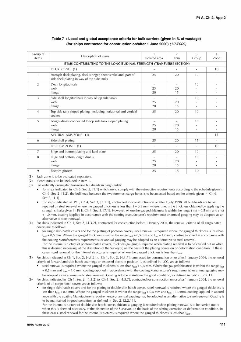
Pt A, Ch 2, App 2
RINA Rules 2012 111
Table 7 : Local and global acceptance criteria for bulk carriers (given in % of wastage)(for ships contracted for construction on/after 1 June 2000) (1/7/2009)
Group of items
Description of items1
Isolated area2
Item3
Group4
Zone
ITEMS CONTRIBUTING TO THE LONGITUDINAL STRENGTH (TRANSVERSE SECTION)
DECK ZONE (1) - - - 10
1 Strength deck plating, deck stringer, sheer strake and part of side shell plating in way of top side tanks
25 20 10 -
2 Deck longitudinalswebflange
-2520
-2015
10--
---
3 Side shell longitudinals in way of top side tankswebflange
-2520
-2015
10--
---
4 Top side tank sloped plating, including horizontal and vertical strakes
25 20 10 -
5 Longitudinals connected to top side tank sloped platingwebflange
-2520
-2015
10--
---
NEUTRAL AXIS ZONE (1) - - - 15
6 Side shell plating 25 20 15 -
BOTTOM ZONE (1) - - - 10
7 Bilge and bottom plating and keel plate 25 20 10 -
8 Bilge and bottom longitudinalswebflange
-2520
-2015
10--
---
9 Bottom girders 25 15 10 -
(1) Each zone is to be evaluated separately.(2) If continuous, to be included in item 1.(3) For vertically corrugated transverse bulkheads in cargo holds:
• For ships indicated in Ch 6, Sec 2, [1.1] which are to comply with the retroactive requirements according to the schedule given in Ch 6, Sec 2, [1.2], the bulkhead between the two foremost cargo holds is to be assessed based on the criteria given in Ch 6, Sec 2, [1.3].
• For ships indicated in Pt E, Ch 4, Sec 3, [7.1.1], contracted for construction on or after 1 July 1998, all bulkheads are to be repaired by steel renewal where the gauged thickness is less than t + 0,5 mm, where t net is the thickness obtained by applying the strength criteria given in Pt E, Ch 4, Sec 3, [7.1]. However, where the gauged thickness is within the range t net + 0,5 mm and t net + 1,0 mm, coating (applied in accordance with the coating Manufacturer’s requirements) or annual gauging may be adopted as an alternative to steel renewal.
(4) For ships indicated in Ch 1, Sec 2, [4.3.2], contracted for construction before 1 January 2004, the renewal criteria of all cargo hatch covers are as follows:• for single skin hatch covers and for the plating of pontoon covers, steel renewal is required where the gauged thickness is less than
tnet + 0,5 mm. Where the gauged thickness is within the range tnet + 0,5 mm and tnet + 1,0 mm, coating (applied in accordance with the coating Manufacturer's requirements) or annual gauging may be adopted as an alternative to steel renewal.For the internal structure of pontoon hatch covers, thickness gauging is required when plating renewal is to be carried out or when this is deemed necessary, at the discretion of the Surveyor, on the basis of the plating corrosion or deformation condition. In these cases, steel renewal for the internal structures is required where the gauged thickness is less than tnet.
(5) For ships indicated in Ch 1, Sec 2, [4.3.2] to Ch 1, Sec 2, [4.3.7], contracted for construction on or after 1 January 2004, the renewal criteria of forward and side hatch coamings on exposed decks in position 1, as defined in ILCC, are as follows:• steel renewal is required where the gauged thickness is less than tnet + 0,5 mm. Where the gauged thickness is within the range tnet
+ 0,5 mm and tnet + 1,0 mm, coating (applied in accordance with the coating Manufacturer's requirements) or annual gauging may
be adopted as an alternative to steel renewal. Coating is to be maintained in good condition, as defined in Sec 2, [2.2.11].(6) For ships indicated in Ch 1, Sec 2, [4.3.2] to Ch 1, Sec 2, [4.3.7], contracted for construction on or after 1 January 2004, the renewal
criteria of all cargo hatch covers are as follows:• for single skin hatch covers and for the plating of double skin hatch covers, steel renewal is required where the gauged thickness is
less than tnet + 0,5 mm. Where the gauged thickness is within the range tnet + 0,5 mm and tnet + 1,0 mm, coating (applied in accord-ance with the coating Manufacturer's requirements) or annual gauging may be adopted as an alternative to steel renewal. Coating is to be maintained in good condition, as defined in Sec 2, [2.2.11]. For the internal structure of double skin hatch covers, thickness gauging is required when plating renewal is to be carried out or when this is deemed necessary, at the discretion of the Surveyor, on the basis of the plating corrosion or deformation condition. In these cases, steel renewal for the internal structures is required where the gauged thickness is less than tnet.

Pt A, Ch 2, App 2
112 RINA Rules 2012
10 Inner bottom plating and hopper tank sloped plating 25 20 10 -
11 Longitudinals connected to inner bottom and hopper tank sloped platingwebflange
-
2520
-
2015
10
--
-
--
OTHER ITEMS
12 Hatch coaming plating (2) (5) 25 20 - -
13 Hatch coaming brackets (5) 30 25 - -
14 Hatch cover top plating (4) (6) 25 20 15 -
15 Hatch cover skirt plating (4) (6) 25 20 - -
16 Hatch cover stiffeners (4) (6) 25 20 - -
17 Transverse bulkheads (3)platingstiffener webstiffener flange
252520
202015
15--
---
18 Side shell frameswebflangebrackets
252020
201515
---
---
19 Topside and hopper tank web frameswebflange
2520
2015
--
--
Group of items
Description of items1
Isolated area2
Item3
Group4
Zone
(1) Each zone is to be evaluated separately.(2) If continuous, to be included in item 1.(3) For vertically corrugated transverse bulkheads in cargo holds:
• For ships indicated in Ch 6, Sec 2, [1.1] which are to comply with the retroactive requirements according to the schedule given in Ch 6, Sec 2, [1.2], the bulkhead between the two foremost cargo holds is to be assessed based on the criteria given in Ch 6, Sec 2, [1.3].
• For ships indicated in Pt E, Ch 4, Sec 3, [7.1.1], contracted for construction on or after 1 July 1998, all bulkheads are to be repaired by steel renewal where the gauged thickness is less than t + 0,5 mm, where t net is the thickness obtained by applying the strength criteria given in Pt E, Ch 4, Sec 3, [7.1]. However, where the gauged thickness is within the range t net + 0,5 mm and t net + 1,0 mm, coating (applied in accordance with the coating Manufacturer’s requirements) or annual gauging may be adopted as an alternative to steel renewal.
(4) For ships indicated in Ch 1, Sec 2, [4.3.2], contracted for construction before 1 January 2004, the renewal criteria of all cargo hatch covers are as follows:• for single skin hatch covers and for the plating of pontoon covers, steel renewal is required where the gauged thickness is less than
tnet + 0,5 mm. Where the gauged thickness is within the range tnet + 0,5 mm and tnet + 1,0 mm, coating (applied in accordance with the coating Manufacturer's requirements) or annual gauging may be adopted as an alternative to steel renewal.For the internal structure of pontoon hatch covers, thickness gauging is required when plating renewal is to be carried out or when this is deemed necessary, at the discretion of the Surveyor, on the basis of the plating corrosion or deformation condition. In these cases, steel renewal for the internal structures is required where the gauged thickness is less than tnet.
(5) For ships indicated in Ch 1, Sec 2, [4.3.2] to Ch 1, Sec 2, [4.3.7], contracted for construction on or after 1 January 2004, the renewal criteria of forward and side hatch coamings on exposed decks in position 1, as defined in ILCC, are as follows:• steel renewal is required where the gauged thickness is less than tnet + 0,5 mm. Where the gauged thickness is within the range tnet
+ 0,5 mm and tnet + 1,0 mm, coating (applied in accordance with the coating Manufacturer's requirements) or annual gauging may be adopted as an alternative to steel renewal. Coating is to be maintained in good condition, as defined in Sec 2, [2.2.11].
(6) For ships indicated in Ch 1, Sec 2, [4.3.2] to Ch 1, Sec 2, [4.3.7], contracted for construction on or after 1 January 2004, the renewal criteria of all cargo hatch covers are as follows:• for single skin hatch covers and for the plating of double skin hatch covers, steel renewal is required where the gauged thickness is
less than tnet + 0,5 mm. Where the gauged thickness is within the range tnet + 0,5 mm and tnet + 1,0 mm, coating (applied in accord-ance with the coating Manufacturer's requirements) or annual gauging may be adopted as an alternative to steel renewal. Coating is to be maintained in good condition, as defined in Sec 2, [2.2.11]. For the internal structure of double skin hatch covers, thickness gauging is required when plating renewal is to be carried out or when this is deemed necessary, at the discretion of the Surveyor, on the basis of the plating corrosion or deformation condition. In these cases, steel renewal for the internal structures is required where the gauged thickness is less than tnet.

Pt A, Ch 2, App 2
RINA Rules 2012 113
20 Floorsplating 25 15 - -
21 Forward and aft peak bulkheadsplatingstiffener webstiffener flange
252520
202015
15--
---
Group of items
Description of items1
Isolated area2
Item3
Group4
Zone
(1) Each zone is to be evaluated separately.(2) If continuous, to be included in item 1.(3) For vertically corrugated transverse bulkheads in cargo holds:
• For ships indicated in Ch 6, Sec 2, [1.1] which are to comply with the retroactive requirements according to the schedule given in Ch 6, Sec 2, [1.2], the bulkhead between the two foremost cargo holds is to be assessed based on the criteria given in Ch 6, Sec 2, [1.3].
• For ships indicated in Pt E, Ch 4, Sec 3, [7.1.1], contracted for construction on or after 1 July 1998, all bulkheads are to be repaired by steel renewal where the gauged thickness is less than t + 0,5 mm, where t net is the thickness obtained by applying the strength criteria given in Pt E, Ch 4, Sec 3, [7.1]. However, where the gauged thickness is within the range t net + 0,5 mm and t net + 1,0 mm, coating (applied in accordance with the coating Manufacturer’s requirements) or annual gauging may be adopted as an alternative to steel renewal.
(4) For ships indicated in Ch 1, Sec 2, [4.3.2], contracted for construction before 1 January 2004, the renewal criteria of all cargo hatch covers are as follows:• for single skin hatch covers and for the plating of pontoon covers, steel renewal is required where the gauged thickness is less than
tnet + 0,5 mm. Where the gauged thickness is within the range tnet + 0,5 mm and tnet + 1,0 mm, coating (applied in accordance with the coating Manufacturer's requirements) or annual gauging may be adopted as an alternative to steel renewal.For the internal structure of pontoon hatch covers, thickness gauging is required when plating renewal is to be carried out or when this is deemed necessary, at the discretion of the Surveyor, on the basis of the plating corrosion or deformation condition. In these cases, steel renewal for the internal structures is required where the gauged thickness is less than tnet.
(5) For ships indicated in Ch 1, Sec 2, [4.3.2] to Ch 1, Sec 2, [4.3.7], contracted for construction on or after 1 January 2004, the renewal criteria of forward and side hatch coamings on exposed decks in position 1, as defined in ILCC, are as follows:• steel renewal is required where the gauged thickness is less than tnet + 0,5 mm. Where the gauged thickness is within the range tnet
+ 0,5 mm and tnet + 1,0 mm, coating (applied in accordance with the coating Manufacturer's requirements) or annual gauging may
be adopted as an alternative to steel renewal. Coating is to be maintained in good condition, as defined in Sec 2, [2.2.11].(6) For ships indicated in Ch 1, Sec 2, [4.3.2] to Ch 1, Sec 2, [4.3.7], contracted for construction on or after 1 January 2004, the renewal
criteria of all cargo hatch covers are as follows:• for single skin hatch covers and for the plating of double skin hatch covers, steel renewal is required where the gauged thickness is
less than tnet + 0,5 mm. Where the gauged thickness is within the range tnet + 0,5 mm and tnet + 1,0 mm, coating (applied in accord-ance with the coating Manufacturer's requirements) or annual gauging may be adopted as an alternative to steel renewal. Coating is to be maintained in good condition, as defined in Sec 2, [2.2.11]. For the internal structure of double skin hatch covers, thickness gauging is required when plating renewal is to be carried out or when this is deemed necessary, at the discretion of the Surveyor, on the basis of the plating corrosion or deformation condition. In these cases, steel renewal for the internal structures is required where the gauged thickness is less than tnet.
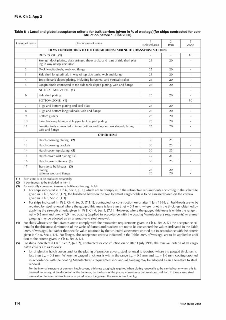
Pt A, Ch 2, App 2
114 RINA Rules 2012
Table 8 : Local and global acceptance criteria for bulk carriers (given in % of wastage)(for ships contracted for con-struction before 1 June 2000)
Group of items Description of items 1Isolated area
2Item
3Zone
ITEMS CONTRIBUTING TO THE LONGITUDINAL STRENGTH (TRANSVERSE SECTION)
DECK ZONE (1) - - 10
1 Strength deck plating, deck stringer, sheer strake and part of side shell plat-ing in way of top side tanks
25 20 -
2 Deck longitudinals, web and flange 25 20 -
3 Side shell longitudinals in way of top side tanks, web and flange 25 20 -
4 Top side tank sloped plating, including horizontal and vertical strakes 25 20 -
5 Longitudinals connected to top side tank sloped plating, web and flange 25 20 -
NEUTRAL AXIS ZONE (1) - - -
6 Side shell plating 25 20 -
BOTTOM ZONE (1) - - 10
7 Bilge and bottom plating and keel plate 25 20 -
8 Bilge and bottom longitudinals, web and flange 25 20 -
9 Bottom girders 25 20 -
10 Inner bottom plating and hopper tank sloped plating 25 20 -
11 Longitudinals connected to inner bottom and hopper tank sloped plating, web and flange
25 20 -
OTHER ITEMS
12 Hatch coaming plating (2) 30 25 -
13 Hatch coaming brackets 30 25 -
14 Hatch cover top plating (5) 30 25 -
15 Hatch cover skirt plating (5) 30 25 -
16 Hatch cover stiffeners (5) 30 25 -
17 Transverse bulkheads (3)platingstiffener web and flange
2525
2020
--
(1) Each zone is to be evaluated separately.(2) If continuous, to be included in item 1.(3) For vertically corrugated transverse bulkheads in cargo holds:
• For ships indicated in Ch 6, Sec 2, [1.1] which are to comply with the retroactive requirements according to the schedule given in Ch 6, Sec 2, [1.2], the bulkhead between the two foremost cargo holds is to be assessed based on the criteria given in Ch 6, Sec 2, [1.3].
• For ships indicated in Pt E, Ch 4, Sec 3, [7.1.1], contracted for construction on or after 1 July 1998, all bulkheads are to be repaired by steel renewal where the gauged thickness is less than t net + 0,5 mm, where t net is the thickness obtained by applying the strength criteria given in Pt E, Ch 4, Sec 3, [7.1]. However, where the gauged thickness is within the range t net + 0,5 mm and t net + 1,0 mm, coating (applied in accordance with the coating Manufacturer’s requirements) or annual gauging may be adopted as an alternative to steel renewal.
(4) For ships whose side shell frames are to comply with the retroactive requirements given in Ch 6, Sec 2, [7] the acceptance cri-teria for the thickness diminution of the webs of frames and brackets are not to be considered the values indicated in the Table (20% of wastage), but rather the specific value obtained by the structural assessment carried out in accordance with the criteria given in Ch 6, Sec 2, [7]. For flanges, the acceptance criteria indicated in the Table (20% of wastage) are to be applied in addi-tion to the criteria given in Ch 6, Sec 2, [7].
(5) For ships indicated in Ch 1, Sec 2, [4.3.2], contracted for construction on or after 1 July 1998, the renewal criteria of all cargo hatch covers are as follows:• for single skin hatch covers and for the plating of pontoon covers, steel renewal is required where the gauged thickness is
less than tnet + 0,5 mm. Where the gauged thickness is within the range tnet + 0,5 mm and tnet + 1,0 mm, coating (applied in accordance with the coating Manufacturer's requirements) or annual gauging may be adopted as an alternative to steel renewal. For the internal structure of pontoon hatch covers, thickness gauging is required when plating renewal is to be carried out or when this is deemed necessary, at the discretion of the Surveyor, on the basis of the plating corrosion or deformation condition. In these cases, steel renewal for the internal structures is required where the gauged thickness is less than tnet.

Pt A, Ch 2, App 2
RINA Rules 2012 115
Figure 15 : Oil tanker: layout of items to be assessed
18 Side shell frames (4)web and flangebrackets
2525
2020
--
19 Topside and hopper tank web frames, web and flange 25 20 -
20 Floorsplating 25 20 -
21 Forward and aft peak bulkheadsplatingstiffener web and flange
2525
2020
--
Group of items Description of items 1Isolated area
2Item
3Zone
(1) Each zone is to be evaluated separately.(2) If continuous, to be included in item 1.(3) For vertically corrugated transverse bulkheads in cargo holds:
• For ships indicated in Ch 6, Sec 2, [1.1] which are to comply with the retroactive requirements according to the schedule given in Ch 6, Sec 2, [1.2], the bulkhead between the two foremost cargo holds is to be assessed based on the criteria given in Ch 6, Sec 2, [1.3].
• For ships indicated in Pt E, Ch 4, Sec 3, [7.1.1], contracted for construction on or after 1 July 1998, all bulkheads are to be repaired by steel renewal where the gauged thickness is less than t net + 0,5 mm, where t net is the thickness obtained by applying the strength criteria given in Pt E, Ch 4, Sec 3, [7.1]. However, where the gauged thickness is within the range t net + 0,5 mm and t net + 1,0 mm, coating (applied in accordance with the coating Manufacturer’s requirements) or annual gauging may be adopted as an alternative to steel renewal.
(4) For ships whose side shell frames are to comply with the retroactive requirements given in Ch 6, Sec 2, [7] the acceptance cri-teria for the thickness diminution of the webs of frames and brackets are not to be considered the values indicated in the Table (20% of wastage), but rather the specific value obtained by the structural assessment carried out in accordance with the criteria given in Ch 6, Sec 2, [7]. For flanges, the acceptance criteria indicated in the Table (20% of wastage) are to be applied in addi-tion to the criteria given in Ch 6, Sec 2, [7].
(5) For ships indicated in Ch 1, Sec 2, [4.3.2], contracted for construction on or after 1 July 1998, the renewal criteria of all cargo hatch covers are as follows:• for single skin hatch covers and for the plating of pontoon covers, steel renewal is required where the gauged thickness is
less than tnet + 0,5 mm. Where the gauged thickness is within the range tnet + 0,5 mm and tnet + 1,0 mm, coating (applied in accordance with the coating Manufacturer's requirements) or annual gauging may be adopted as an alternative to steel renewal. For the internal structure of pontoon hatch covers, thickness gauging is required when plating renewal is to be carried out or when this is deemed necessary, at the discretion of the Surveyor, on the basis of the plating corrosion or deformation condition. In these cases, steel renewal for the internal structures is required where the gauged thickness is less than tnet.
ZONE
BOTTOM ZONE
NEUTRAL AXIS
DECK ZONE
23
11
5
9
86
14
12 10
718
16
17
15
14
13

Pt A, Ch 2, App 2
116 RINA Rules 2012
Table 9 : Local and global acceptance criteria for oil tankers (given in % of wastage)(for ships contracted for con-struction on/after 1 June 2000) (1/7/2009)
Group of items
Description of items1
Isolated area2
Item3
Group4
Zone
ITEMS CONTRIBUTING TO THE LONGITUDINAL STRENGTH (TRANSVERSE SECTION)
DECK ZONE (1) - - - 10
1 Deck plating, deck stringer, sheer strake and longitudinal bulkhead upper strake (2)
25 20 10 -
2 Deck and sheer strake longitudinalswebflange
-2520
-2015
10--
---
3 Deck longitudinal girderswebflange
-2520
-2015
10--
---
4 Longitudinals connected to long. bulkhead upper strake (2)webflange
-2520
-2015
10--
---
NEUTRAL AXIS ZONE (1) - - - 15
5 Side shell plating (2) 25 20 15 -
6 Side shell longitudinals and stringers (2)webflange
-2520
-2015
15--
---
7 Longitudinal bulkhead plating 25 20 15 -
8 Longitudinal bulkhead longitudinals and stringerswebflange
-2520
-2015
15--
---
BOTTOM ZONE (1) - - - 10
9 Bilge and bottom strakes, longitudinal bulkhead lower strake and keel plate (2)
25 20 10 -
10 Bilge and bottom longitudinals (2)webflange
-2520
-2015
10--
---
11 Longitudinals connected to longitud. bulkhead lower strakewebflange
-2520
-2015
10--
---
12 Bottom girderswebflange
-2520
-2015
10--
---
OTHER ITEMS
13 Deck transverse web framewebflangebrackets / stiffeners
252025
201520
---
---
14 Side shell web framewebflangebrackets / stiffeners
252025
201520
---
---
(1) Each zone is to be evaluated separately.(2) For double hull oil tankers, the structural elements of the inner skin (plating, longitudinals, girders, bulkheads) are to be
included in the corresponding elements of the outer skin. (3) Including swash bulkheads, forward and aft peak bulkheads.

Pt A, Ch 2, App 2
RINA Rules 2012 117
Table 10 : Local and global acceptance criteria for oil tankers (given in % of wastage)(for ships contracted for construction before 1 June 2000)
15 Longitudinal bulkhead web framewebflangebrackets / stiffeners
252025
201520
---
---
16 Bottom transverse web framewebflangebrackets / stiffeners
252025
201520
---
---
17 Cross tiewebflangebrackets / stiffeners
252020
151515
---
---
18 Transverse bulkheads (3)platingstringer webstringer flangestiffener webstiffener flange
2525203025
2020152015
15----
-----
Group of items
Description of items1
Isolated area2
Item3
Group4
Zone
(1) Each zone is to be evaluated separately.(2) For double hull oil tankers, the structural elements of the inner skin (plating, longitudinals, girders, bulkheads) are to be
included in the corresponding elements of the outer skin. (3) Including swash bulkheads, forward and aft peak bulkheads.
Group of items
Description of items1
Isolated area2
Item3
Zone
ITEMS CONTRIBUTING TO THE LONGITUDINAL STRENGTH (TRANSVERSE SECTION)
DECK ZONE (1) - - 10
1 Deck plating, deck stringer, sheer strake and longitudinal bulkhead upper strake (2)
25 20 -
2 Deck and sheer strake longitudinals, web and flange 25 20 -
3 Deck longitudinal girders, web and flange 25 20 -
4 Longitudinals connected to long. bulkhead upper strake (2)web and flange 25 20 -
NEUTRAL AXIS ZONE (1) - - -
5 Side shell plating (2) 25 20 -
6 Side shell longitudinals and stringers (2)web and flange 25 20 -
7 Longitudinal bulkhead plating 25 20 -
8 Longitudinal bulkhead longitudinals and stringers, web and flange 25 20 -
BOTTOM ZONE (1) - - 10
9 Bilge and bottom strakes, longitudinal bulkhead lower strake and keel plate (2)
25 20 -
(1) Each zone is to be evaluated separately.(2) For double hull oil tankers, the structural elements of the inner skin (plating, longitudinals, girders, bulkheads) are to be
included in the corresponding elements of the outer skin. (3) Including swash bulkheads, forward and aft peak bulkheads.

Pt A, Ch 2, App 2
118 RINA Rules 2012
10 Bilge and bottom longitudinals (2)web and flange
25 20 -
11 Longitudinals connected to longitud. bulkhead lower strake, web and flange
25 20 -
12 Bottom girders, web and flange 25 20 -
OTHER ITEMS
13 Deck transverse web frameweb and flangebrackets / stiffeners
2525
2020
--
14 Side shell web frameweb and flangebrackets / stiffeners
2525
2020
--
15 Longitudinal bulkhead web frameweb and flangebrackets / stiffeners
2525
2020
--
16 Bottom transverse web frameweb and flangebrackets / stiffeners
2525
2020
--
17 Cross tieweb and flangebrackets / stiffeners
2525
2020
--
18 Transverse bulkheads (3)platingstringer web and flangestiffener web and flange
252525
202020
---
Group of items
Description of items1
Isolated area2
Item3
Zone
(1) Each zone is to be evaluated separately.(2) For double hull oil tankers, the structural elements of the inner skin (plating, longitudinals, girders, bulkheads) are to be
included in the corresponding elements of the outer skin. (3) Including swash bulkheads, forward and aft peak bulkheads.

Pt A, Ch 2, App 3
RINA Rules 2012 119
APPENDIX 3 CRITERIA FOR LONGITUDINAL STRENGTH OF
THE HULL GIRDER
1 General
1.11.1.1 (1/7/2005)These criteria are to be used for the evaluation of longitudi-nal strength of the ship's hull girder as required by Sec 2,[2.3.9].
In order for the evaluation of the ship's longitudinal strengthto be recognised as valid, fillet welding between longitudi-nal internal members and hull envelopes is to be in soundcondition so as to keep integrity of longitudinal internalmembers with hull envelopes.
Items [1.1.2] and [6] only apply to oil tankers.
1.1.2 (1/7/2005)On oil tankers, both for single and double hull construction,of 130 m in length and upwards and of over 10 years of age,the longitudinal strength of the ship's hull girder is to beevaluated in compliance with the requirements of thisApp 3 on the basis of the thickness measured, renewed orreinforced, as appropriate, during the class renewal survey.
The condition of the hull girder for longitudinal strengthevaluation is to be determined in accordance with themethods specified in [6].
2 Calculation of transverse sectional areas of deck and bottom flanges of hull girder
2.12.1.1 (1/7/2002)The transverse sectional areas of deck zones and bottomzones (as defined in App 2, [4.3.4]) of the ship's hull girderare to be calculated by using the thickness measured,renewed or reinforced, as appropriate, during the classrenewal survey.
2.1.2 (1/7/2002)If the diminution of sectional areas of either deck or bottomzones exceeds 10 % of their respective as-built area (i.e.original sectional area when the ship was built), either ofthe following measures is to be taken:
a) renewal or reinforcement of the deck or bottom zonesso that the actual sectional area is not less than 90% ofthe as-built area; or
b) calculation of the actual section moduli (Zact) of thetransverse section of the ship's hull girder by applyingthe calculation method specified in [4], using the thick-ness measured, renewed or reinforced, as appropriate,during the class renewal survey.
3 Requirements for transverse section modulus of hull girder
3.1
3.1.1 (1/7/2002)The actual section moduli (Zact) of the transverse section ofthe ship's hull girder calculated in accordance with[2.1.2]b) above is not to be less than 90% of the requiredsection modulus ZR or ZR,MIN for new buildings specified inPt B, Ch 6, Sec 2, [4.2], whichever is the greater, providedthat in no case is Zact less than the diminution limit of theminimum section modulus (ZMC) as specified in [5].
4 Calculation criteria of section moduli of midship section of hull girder
4.1
4.1.1 (1/7/2002)When calculating the transverse section modulus of theship's hull girder, the sectional area of all continuous longi-tudinal strength members is to be taken into account.
4.1.2 (1/7/2002)Large openings, i.e. openings exceeding 2,5m in length or1,2m in breadth and scallops, where scallop welding isapplied, are always to be deducted from the sectional areasused in the section modulus calculation.
4.1.3 (1/7/2002)Smaller openings (manholes, lightening holes, single scal-lops in way of seams, etc.) need not be deducted providedthat the sum of their breadths or shadow area breadths inone transverse section does not reduce the section modulusat deck or bottom by more than 3% and provided that theheight of lightening holes, draining holes and single scal-lops in longitudinals or longitudinal girders does not exceed25% of the web depth, for scallops of maximum 75mm.
4.1.4 (1/7/2002)A deduction-free sum of smaller opening breadths in onetransverse section in the bottom or deck area of 0,06(B - Σb)(where B = breadth of ship, Σb = total breadth of largeopenings) may be considered equivalent to the abovereduction in section modulus.
4.1.5 (1/7/2002)The shadow area is to be obtained by drawing two tangentlines with an opening angle of 30°.
4.1.6 (1/7/2002)The deck modulus is related to the moulded deck line atside.

Pt A, Ch 2, App 3
120 RINA Rules 2012
4.1.7 (1/7/2002)The bottom modulus is related to the base line.
4.1.8 (1/7/2002)Continuous trunks and longitudinal hatch coamings are tobe included in the longitudinal sectional area provided theyare effectively supported by longitudinal bulkheads or deepgirders. The deck modulus is then to be calculated by divid-ing the moment of inertia by the following distance, pro-vided this is greater than the distance to the deck line atside:
where:
y : distance from neutral axis to top of continuousstrength member,
x : distance from top of continuous strength mem-ber to centreline of the ship.
x and y to be measured to the point giving the largest valueof yt.
4.1.9 (1/7/2002)Longitudinal girders between multi-hatchways are to beconsidered by means of special calculations.
5 Diminution limit of minimum longitu-dinal strength of ships in service
5.15.1.1 (1/7/2002)The diminution limit of the minimum section modulus Zmc,in cm3, of ships in service is given by the following formula:
where:
L : length of ships. L is the distance, in meters, onthe summer load waterline from the fore side ofstem to the after side of the rudder post, or thecentre of the rudder stock if there is no rudderpost. L is not to be less than 96%, and need notbe greater than 97%, of the extreme length onthe summer load waterline. In ships with unu-sual stern and bow arrangement the length Lmay be specially considered.
B : greatest moulded breadth in metres.
Cb : moulded block coefficient at draught d corre-sponding to summer load waterline, based on Land B. Cb is not to be taken less than 0.60,according to the formula:
c : 0,9 cn (the value of Cn is given in Tab 1)
k : material factor, e.g:
k = 1 for mild steel with yield stress of235N/mm2 and over;
k = 0,78 for high tensile steel with yield stress of315 N/mm2 and over,
k = 0,72 for high tensile steel with yield stress of355 N/mm2 and over.
5.1.2 (1/7/2002)Scantlings of all continuous longitudinal members of theship's hull girder based on the section modulus requirementin [5.1.1] above are to be maintained within 0,4 L amid-ships. However, in special cases, based on consideration ofthe type of ship, hull form and loading conditions, thescantlings may be gradually reduced towards the end of 0,4L part, bearing in mind the desire not to inhibit the ship'sloading flexibility.
5.1.3 (1/7/2002)However, the above standard may not be applicable toships of unusual type or design, e.g. for ships of unusualmain proportions and/or weight distributions.
6 Oil tankers - Sampling method of thickness measurements for longitu-dinal strength evaluation and repair methods
6.1 Extent of longitudinal strength evalua-tion
6.1.1 (1/7/2005)Longitudinal strength is to be evaluated within 0,4L amid-ships for the extent of the hull girder length that containstanks therein and within 0,5L amidships for adjacent tankswhich may extend beyond 0,4L amidships, where tanksmeans ballast tanks and cargo tanks.
6.2 Sampling method of thickness measure-ment
6.2.1 (1/7/2005)Pursuant to the requirements of Ch 4, Sec 3, [6.4], for singlehull oil tanker or Ch 4, Sec 4, [4.4] for double haull oiltankers, transverse sections are to be chosen such that thick-ness measurements can be taken for as many different tanksin corrosive environments as possible, e.g. ballast tankssharing a common plane boundary with cargo tanks fittedwith heating coils, other ballast tanks, cargo tanks permittedto be filled with sea water and other cargo tanks. Ballasttanks sharing a common plane boundary with cargo tanksfitted with heating coils and cargo tanks permitted to befilled with sea water are to be selected where present.
Table 1 : Values of Cn
yL y 0 9 0 2x B⁄,+,( )=
Zmc cL2B Cb 0 7,+( )k=
Cbmoulded deplacement m3( )at drau ght d
LBd-------------------------------------------------------------------------------------------------------------=
L < 90 90 ≤ L < 300 300 ≤ L ≤ 350 350 < L ≤ 500
Cn 118 0 36L,–( ) L 1000⁄⋅ 10 75 300 L–( ) 100⁄[ ]1 5,–, 10 75, 10 75 L 350–( ) 150⁄[ ]1 5,–,
Pt A, Ch 2, App 3
RINA Rules 2012 121
6.2.2 (1/7/2005)
The minimum number of transverse sections to be sampledis to be in accordance with Ch 4, Sec 3, Tab 3 for singlehull oil tankers or Ch 4, Sec 4, Tab 3 for double hull oiltankers. The transverse sections are to be located where thelargest thickness reductions are suspected to occur or arerevealed from deck and bottom plating measurements pre-scribed in [6.2.3] and are to be clear of areas which havebeen locally renewed or reinforced.
6.2.3 (1/7/2005)
At least two points are to be measured on each deck plateand/or bottom shell plate required to be measured withinthe cargo area in accordance with the requirements ofCh 4, Sec 3, Tab 3 for single hull oil tankers or Ch 4, Sec 4,Tab 3for double hull oil tankers.
6.2.4 (1/7/2005)
Within 0,1D (where D is the ship's moulded depth) of thedeck and bottom at each transverse section to be measuredin accordance with the requirements of Ch 4, Sec 3, Tab 3for single hull oil tankers or Ch 4, Sec 4, Tab 3 for doublehull oil tankers, every longitudinal and girder is to be meas-ured on the web and face plate, and every plate is to bemeasured at one point between longitudinals.
6.2.5 (1/7/2005)
For longitudinal members other than those specified in[6.2.4] to be measured at each transverse section in accord-ance with the requirements of Ch 4, Sec 3, Tab 3 for singlehull oil tankers or Ch 4, Sec 4, Tab 3 for double hull oiltankers, every longitudinal and girder is to be measured onthe web and face plate, and every plate is to be measured atleast in one point per strake.
6.2.6 (1/7/2005)
The thickness of each component is to be determined byaveraging all of the measurements taken in way of the trans-verse section on each component.
6.3 Additional measurements where the lon-gitudinal strength is deficient
6.3.1 (1/7/2005)
Where one or more of the transverse sections are found tobe deficient in respect of the longitudinal strength require-ments given in this App 3, the number of transverse sectionsfor thickness measurement is to be increased such that eachtank within the 0,5L amidships region has been sampled.Tank spaces that are partially within, but extend beyond,the 0,5L region are to be sampled.
6.3.2 (1/7/2005)Additional thickness measurements are also to be per-formed on one transverse section forward and one aft ofeach repaired area to the extent necessary to ensure that theareas bordering the repaired section also comply with therequirements of Ch 4, Sec 3 for single hull oil tankers orCh 4, Sec 4 for double hull oil tankers.
6.4 Effective repair methods6.4.1 (1/7/2005)The extent of renewal or reinforcement carried out to com-ply with this App 3 is to be in accordance with [6.4.2].
6.4.2 (1/7/2005)The minimum continuous length of a renewed or reinforcedstructural member is to be not less than twice the spacing ofthe primary members in way. In addition, the thickness dim-inution in way of the butt-joint of each joining member for-ward and aft of the replaced member (plates, stiffeners,girder webs and flanges, etc.) is not to be within the sub-stantial corrosion range (75% of the allowable diminutionassociated with each particular member). Where differ-ences in thickness at the butt-joint exceed 15% of the lowerthickness, a transition taper is to be provided.
6.4.3 (1/7/2005)Alternative repair methods involving the fitting of straps orstructural member modification are subject to special con-sideration. When considered, the fitting of straps is to belimited to the following conditions:
a) to restore and/or increase longitudinal strength;
b) the thickness diminution of the deck or bottom platingto be reinforced is not within the substantial corrosionrange (75% of the allowable diminution associated withthe deck plating);
c) the alignment and arrangement, including the termina-tion of the straps, are in accordance with a standard rec-ognised by the Society;
d) the straps are continuous over the entire 0,5L amidshipslength; and
e) continuous fillet welding and full penetration welds areused for butt welding and, depending on the width ofthe strap, for slot welds. The welding proceduresapplied are acceptable to the Society.
6.4.4 (1/7/2005)The existing structure, adjacent to replacement areas and inconjunction with the fitted straps, etc., is to be capable ofwithstanding the applied loads, taking into account thebuckling resistance and the condition of welds between thelongitudinal members and hull envelope plating.


RINA Rules 2012 123
Part AClassification and Surveys
Chapter 3
SCOPE OF SURVEYS (all ships)
SECTION 1 SURVEY FOR NEW CONSTRUCTION
SECTION 2 SURVEY FOR ASSIGNMENT OF CLASS OF A SHIP IN SERVICE
SECTION 3 ANNUAL SURVEY
SECTION 4 INTERMEDIATE SURVEY
SECTION 5 CLASS RENEWAL SURVEY
SECTION 6 BOTTOM SURVEY
SECTION 7 TAILSHAFT SURVEY
SECTION 8 BOILER SURVEY
APPENDIX 1 CLASS REQUIREMENTS AND SURVEYS OF LAID-UP SHIPS


Pt A, Ch 3, Sec 1
RINA Rules 2012 125
SECTION 1 SURVEY FOR NEW CONSTRUCTION
1 Hull
1.1 General
1.1.1 Scope (1/1/2008)
The scope of this Section includes the following main activ-ities:
a) Examination of the parts of the ship covered by classifi-cation Rules and by applicable statutory regulations forhull construction, to obtain appropriate evidence thatthey have been built in compliance with the Rules andregulations, taking account of the relevant approveddrawings.
b) Appraisal of the manufacturing, construction, controland qualification procedures, including welding con-sumables, weld procedures, weld connections andassemblies, with indication of relevant approval tests.
c) Witnessing inspections and tests as required in the clas-sification Rules used for ship construction includingmaterials, welding and assembling, with specification ofthe items to be examined and/or tested, the methods(e.g. by hydrostatic, hose or leak testing, non-destructiveexamination, verification of geometry) and who is tocarry out such inspections and tests.
Appraisal of materials and equipment used for ship con-struction and their inspection at works is not included inthis Section. Details of requirements for hull and machinerysteel forgings and castings and for normal and higherstrength hull structural steel are given in Pt D, Ch 2, Sec 3,Pt D, Ch 2, Sec 4 and Pt D, Ch 2, Sec 1, [2] respectively.Acceptance of these items is verified through the surveyprocess carried out at the Manufacturer's works and theissuing of the appropriate certificates.
1.2 Definitions
1.2.1 Hull structure (1/1/2008)
The hull structure (see Note 1) is defined as follows:
a) hull envelope including all internal and external struc-tures,
b) superstructures, deckhouses and casings,
c) welded foundations, e.g. main engine seatings,
d) hatch coamings, bulwarks,
e) all penetrations fitted and welded into bulkheads, decksand shell,
f) the fittings of all connections to decks, bulkheads andshell, such as air pipes and ship side valves - all items ofILLC 1966, as amended,
g) welded attachments to shell, decks and primary mem-bers, e.g. crane pedestals, bitts and bollards, but only asregards their interaction on the hull structure.
Note 1: A glossary of hull terms and hull survey terms can be foundin IACS Recommendation 82.
1.2.2 Documents (1/1/2008)
Reference to documents also includes electronic transmis-sion or storage.
1.2.3 Survey methods (1/7/2010)
The survey methods which the Surveyor is directly involvedin are as follows:
a) Patrol is defined as the act of checking on an independ-ent and unscheduled basis that the applicable proc-esses, activities and associated documentation of theshipbuilding functions identified in Tab 1 continue toconform to classification and statutory requirements.
b) Review is defined as the act of examining documents inorder to determine traceability and identification, and toconfirm that processes continue to conform to classifi-cation and statutory requirements.
c) Witness is defined as the attendance at scheduledinspections in accordance with the agreed Inspectionand Test Plans or equivalent to the extent necessary tocheck compliance with the survey requirements.
1.3 Application
1.3.1 Classification items (1/1/2008)
This Section covers the survey of all new construction ofsteel ships intended for classification and for internationalvoyages except for:
a) those defined in SOLAS I/3
b) high speed craft as defined in I/1.3.1 of the 2000 HighSpeed Craft Code
c) Mobile Offshore Drilling Units as defined in I/1.2.1 ofthe MODU Code.
1.3.2 Statutory items (1/7/2010)
This Section covers all statutory items relevant to the hullstructure and coating, i.e. Load Line and SOLAS Safety Con-struction.

Pt A, Ch 3, Sec 1
126 RINA Rules 2012
1.3.3 Equipment, fittings and appendages (1/1/2008)
This Section does not cover the manufacture of equipment,fittings and appendages regardless of whether they aremade inside or outside the shipyard, examples being as fol-lows:
a) hatch covers,
b) doors and ramps integral with the shell and bulkheads,
c) rudders and rudder stock,
d) all forgings and castings integral to the hull.
Evidence of acceptance is to be provided by accompanyingdocumentation from the Surveyor at the Manufacturer's andverified at the shipyard.
1.3.4 Installation, welding and testing (1/1/2008)
This Section applies to the installation in the ship, weldingand testing of:
a) the items listed in [1.3.3] above
b) equipment forming part of the watertight and weather-tight integrity of the ship.
1.3.5 Location of construction (1/7/2010)
This Section applies to the hull structures and coating con-structed:
a) at the shipbuilder's facilities,
b) by subcontractors at the shipbuilder's facilities,
c) by subcontractors at their own facilities or at otherremote locations.
1.4 Personnel
1.4.1 Qualification and monitoring of exclusive Surveyors (1/7/2010)
The Society's Surveyors are to confirm through patrol,review and witness, as defined in [1.2.3], that ships are builtusing approved plans in accordance with the relevant Rulesand statutory requirements. The Surveyors are to be quali-fied to be able to carry out their tasks, and procedures are tobe in place to ensure that their activities are monitored.
1.5 Survey of the hull structure
1.5.1 Surveyable items (1/7/2010)
Tab 1 provides a list of surveyable items for the hull struc-ture and coating covered by this Section, including:
a) description of the shipbuilding functions;
b) classification and statutory survey requirements;
c) survey method required for classification;
d) relevant Society Rule and statutory requirement refer-ences;
e) documentation to be available for the Surveyor duringconstruction. The shipbuilder is to provide the Surveyorswith access to documentation required by the Society;this includes documentation retained by the shipbuilderor other third parties. The list of documents approved or
reviewed by the Society for the specific new construc-tion is as follows:
1) plans and supporting documents,
2) examination and testing plans,
3) NDE plans,
4) welding consumable details,
5) welding procedure specifications,
6) welding plan or details,
7) welders' qualification records,
8) NDE operators' qualification records;
f) documents to be inserted into the ship construction file.Refer to [1.10] for details;
g) a list of specific activities which are relevant to the ship-building functions. This list is not exhaustive and can bemodified to reflect the construction facilities or specificship type.
1.5.2 Materials and equipment supplied (1/1/2008)During the construction process as required, evidence isalso to be made available by the shipbuilder to the Surveyorto prove that the materials and equipment supplied to theship have been built or manufactured under survey relevantto the classification Rules and statutory requirements.
1.6 Review of the shipyard
1.6.1 Review of the construction facilities (1/7/2010)The Society is to familiarise itself with the yard's productionfacilities, management processes and safety for considera-tion in terms of compliance with the requirements of Tab 1(see Note 1) prior to any steelwork or construction takingplace in the following circumstances:
a) where the Society has no, or no recent, experience ofthe construction facilities - typically after a one yearlapse - or when significant new infrastructure has beenadded,
b) where there has been significant management or per-sonnel restructuring having an impact on the ship con-struction process, or
c) where the shipbuilder contracts to construct a ship of adifferent type or substantially different in design.
Note 1: Reference is made to [1.11] - Shipyard review record, asan example.
1.7 Newbuilding survey planning
1.7.1 Kick-off meeting (1/7/2010)Prior to commencement of surveys for any newbuildingproject, the Society is to discuss with the shipbuilder at akick-off meeting the items listed in Tab 1. The purpose ofthe meeting is to agree how the list of specific activitiesshown in Tab 1 is to be addressed. The meeting is to takeinto account the shipbuilder's construction facilities andship type, including the list of proposed subcontractors. Arecord of the meeting is to be made, based on the contentsof Tab 1. Tab 1 itself can be used as the record with com-ments made in the appropriate column. If the Society hasappointed a Surveyor for a specific newbuilding projectthen this Surveyor is to attend the kick-off meeting. The

Pt A, Ch 3, Sec 1
RINA Rules 2012 127
builder is to be asked to agree to undertake ad hoc investi-gations during construction where areas of concern ariseand to keep the Society advised of the progress of any suchinvestigation. Whenever an investigation is undertaken, thebuilder is to be requested, in principle, to agree to suspendrelevant construction activities if warranted by the severityof the problem.
1.7.2 Specific Administration and statutory requirements (1/1/2008)
The records are to take note of specific published Adminis-tration requirements and interpretations of statutory require-ments.
1.7.3 Construction progress records (1/7/2010)
The shipyard shall be requested to advise of any changes tothe activities agreed at the kick-off meeting and these are tobe documented. For instance, if the shipbuilder chooses touse or change subcontractors, or to incorporate any modifi-cations necessitated by changes in production or inspectionmethods, rules and regulations, structural modifications, orin the event where increased inspection requirements aredeemed necessary as a result of a substantial non-conform-ance or otherwise.
1.7.4 Fabrication quality standard (1/7/2010)
Shipbuilding quality standards for the hull structure duringnew construction are to be reviewed and agreed during thekick-off meeting. Structural fabrication is to be carried outin accordance with IACS Recommendation 47, "Shipbuild-ing and Repair Quality Standard", or a recognised fabrica-tion standard which has been accepted by the Society priorto the commencement of fabrication/construction. Thework is to be carried out in accordance with the Rules andunder survey of the Society.
1.7.5 Other attendees at the kick-off meeting (1/1/2008)
The kick-off meeting may be attended by other parties, suchas the Owner or Administrations, subject to agreement bythe shipbuilder.
1.7.6 Special cases of kick-off meeting (1/7/2010)
In the event of series ship production, consideration may begiven to waiving the requirement for a kick-off meeting forthe second and subsequent ships provided any changes aredocumented as required in [1.7.1].
1.8 Examination and test plan for newbuild-ing activities
1.8.1 Plans to be provided (1/1/2008)
The shipbuilder is to provide plans of the items which areintended to be examined and tested. These plans need not
be submitted for approval and examination at the time ofthe kick-off meeting. They are to include:
a) proposals for the examination of completed steelwork -generally referred to as the block plan and includingdetails of joining blocks together at the pre-erection anderection stages or at other relevant stages;
b) proposals for fit-up examinations where necessary;
c) proposals for testing of the structure (leak and hydro-static) as well as for all watertight and weathertight clos-ing appliances;
d) proposals for non-destructive examination;
e) any other proposals specific to the ship type or to thestatutory requirements.
1.8.2 Submittal of plans to the Surveyors (1/7/2010)
The plans and any modifications to them are to be submit-ted to the Surveyors in sufficient time to allow review beforethe relevant survey activity commences.
1.9 Proof of the consistency of surveys
1.9.1 Evidence for survey planning and activities (1/1/2008)
Inspection and test records, checklists etc are to be kept inorder to provide evidence that the Society's Surveyors havecomplied with the requirements of the newbuilding surveyplanning and duly participated in the relevant activitiesshown in the shipbuilder's examination and test plans.
1.10 Ship Construction File
1.10.1 Document provider (1/7/2010)
The shipbuilder is to deliver documents for the Ship Con-struction File. In the event that items have been provided byanother Party such as the Shipowner, and where separatearrangements have been made for document deliveryexcluding the shipbuilder, that Party has the responsibility.
The Ship Construction File is to be reviewed for content inaccordance with the requirements of [1.10.2].
1.10.2 Contents of the Ship Construction File (1/7/2010)
It is recognised that the purpose of documents held in theShip Construction File on board the ship is to facilitate sur-veys and repairs and maintenance, and, therefore, in addi-tion to those listed in Tab 1, such documents are to include,but not be limited to, the following:
a) as-built structural drawings including scantling details,material details and, as applicable, wastage allowances,location of butts and seams, cross-section details andlocations of all partial and full penetration welds, areasidentified for close attention and rudders;

Pt A, Ch 3, Sec 1
128 RINA Rules 2012
b) manuals required for classification and statutoryrequirements, e.g. loading and stability, bow doors,inner doors, side shell doors and stern doors - opera-tions and maintenance manuals ( Pt B, Ch 9, Sec 5 andPt B, Ch 9, Sec 6);
c) ship structure access manual, as applicable;
d) copies of certificates of forgings and castings weldedinto the hull ( Pt D, Ch 2, Sec 3 and Pt D, Ch 2, Sec 4);
e) details of equipment forming part of the watertight andweathertight integrity of the ship;
f) tank testing plan including details of the test require-ments ( Pt B, Ch 12, Sec 3);
g) corrosion protection specifications ( Pt B, Ch 11, Sec 1and Pt E, Ch 4, Sec 3, [10]);
h) details for the in-water survey, if applicable, informationfor divers, clearance measurement instructions etc, tankand compartment boundaries;
i) docking plan and details of all penetrations normallyexamined at dry-docking;
j) Coating Technical File, for ships subject to compliancewith the IMO Performance Standard for Protective Coat-
ings (PSPC), as a class requirement under the IACSCommon Structural Rules.
1.11 Shipyard review record
1.11.1 Contents of the shipyard review record (1/1/2008)
The shipyard review record is to contain the following infor-mation, for which the Society form "Shipyard review record"is to be filled in as appropriate:
a) name and location of shipyard
b) details of any management systems
c) construction facilities
d) shipyard control of qualified welders
e) features of construction procedure
f) quality control system
g) measures for safety and health
h) control system of non-destructive examination (NDE)
i) quality control on production line.

Pt A, Ch 3, Sec 1
RINA Rules 2012 129
Table 1 : New construction survey activities (1/7/2010)
No.Shipbuilding quality con-trol function
Survey Requirements for Classifica-
tion
Survey Method
required for Classifica-
tion
Society Rule refer-
ence
Statutory require-
ments and relevant
reference
Docu-menta-
tion available to Sur-
veyor dur-ing
construc-tion
Docu-menta-tion for
Ship Con-struction
File
Specific activities
Society proposals
for the project
1 Welding:
1.1 Welding con-sumables
Approved by Society sepa-rately at the Manufac-turer's
Review approval status and patrol, ver-ify storage, handling and treat-ment in accord-ance with Manufac-turer's require-ments
Pt D, Ch 5, Sec 2
Consuma-ble speci-fication and approval status
Not required
Identify con-sumables against approved list
Verify tem-porary and permanent storage facil-ities
E.g. kept dry, cov-ered, where applica-ble heated
Verify trace-ability
E.g. ran-dom batch number checking
1.2 Welder quali-fication
Qualified welders
Review of welder cer-tification and patrol
Guide for Welding
Ship-yard's records with indi-vidual's identifica-tion
Not required
Verify welder qual-ification standard, e.g. class or recognised standard approval
Verify welder approved for weld posi-tion
Verify valid-ity of qualifi-cation certificate

Pt A, Ch 3, Sec 1
130 RINA Rules 2012
1.3 Welding - mechanical properties (welding pro-cedures)
All weld joint configura-tions, posi-tions and materials to be covered by weld proce-dures approved by the Society or by another QSCS Classifi-cation Society avail-able
Review and patrol
Pt D, Ch 5, Sec 4
Approved weld pro-cedure specifica-tion and welding plan rele-vant to the ship project or process
Not required
Verify proce-dures are available at relevant workstations
The Society witnesses all new weld procedure qualification tests carried out in the shipyard whenever the Society is sur-veying in the shipyard
Witness Verify weld procedure records have been approved and cover all weld proc-esses and positions in accordance with classifi-cation or recognised standards and are available for the Sur-veyor's refer-ence
1.3a Welding equipment
Correctly cali-brated and maintained
Patrol and review
Ship-builder's mainte-nance and calibra-tion records
Not required
Verify condi-tion of machinery and equip-ment
Verify machines are cali-brated by appropriate staff
No.Shipbuilding quality con-trol function
Survey Requirements for Classifica-
tion
Survey Method
required for Classifica-
tion
Society Rule refer-
ence
Statutory require-
ments and relevant
reference
Docu-menta-
tion available to Sur-
veyor dur-ing
construc-tion
Docu-menta-tion for
Ship Con-struction
File
Specific activities
Society proposals
for the project

Pt A, Ch 3, Sec 1
RINA Rules 2012 131
1.3aCont’d
Welding equipment
Verify cali-bration car-ried out in accordance with Manu-facturer's recommen-dations
Verify cali-bration in accordance with mainte-nance schedule
1.3b Welding environment
Satisfactory environment
Patrol Guide for welding
Not required
Verify weld-ing areas clean, dry, well lit
Confirm rel-evant meas-ures taken for any pre- or post- heat treatment, drying of surfaces prior to welding
Confirm shielding gases, fluxes protected
1.3c Welding supervision
Sufficient number of skilled super-visors
Patrol - Guide for welding- Rules for carrying out non-destructive examina-tions of welding
Verify super-vision is effective
No.Shipbuilding quality con-trol function
Survey Requirements for Classifica-
tion
Survey Method
required for Classifica-
tion
Society Rule refer-
ence
Statutory require-
ments and relevant
reference
Docu-menta-
tion available to Sur-
veyor dur-ing
construc-tion
Docu-menta-tion for
Ship Con-struction
File
Specific activities
Society proposals
for the project

Pt A, Ch 3, Sec 1
132 RINA Rules 2012
1.4 Welding- sur-face disconti-nuities
Substantially free from sig-nificant indi-cations, satisfactory profile and size
Visual examina-tion, sur-face detection tech-niques, review of documents and patrol of operator
- Guide for welding- Rules for carrying out non-destructive examina-tions of welding
Ship-builder's and rec-ognised standards and Rules as appli-cable, welding and NDE plans, NDE reports, operator qualifica-tions
Not required
Identify worksta-tions where NDE is car-ried out, e.g. panel line butt welds, castings into hull struc-ture
Verify NDE carried out in accord-ance with approved plans where applicable
Verify suita-bility of NDE methods
Verify opera-tors suitably qualified, particularly where sub-contractors have been employed
Verify NDE is carried out according to the accepta-ble process
Review NDE records
No.Shipbuilding quality con-trol function
Survey Requirements for Classifica-
tion
Survey Method
required for Classifica-
tion
Society Rule refer-
ence
Statutory require-
ments and relevant
reference
Docu-menta-
tion available to Sur-
veyor dur-ing
construc-tion
Docu-menta-tion for
Ship Con-struction
File
Specific activities
Society proposals
for the project

Pt A, Ch 3, Sec 1
RINA Rules 2012 133
1.5 Welding - embedded discontinui-ties
NDE is to be carried out by qualified operators capable of ensuring that welds are sub-stantially free from signifi-cant indica-tions
Radiogra-phy and ultrasonic testing, review of documents and patrol of opera-tor, exami-nation of films
- Guide for Welding- Rules for carrying out non-destructive examina-tions of welding
Ship-builder's and rec-ognised standards and Rules as appli-cable, welding and NDE plans, NDE reports, operator qualifica-tions
Not required
Identify worksta-tions where NDE is car-ried out, e.g. panel line butt welds, castings into hull struc-ture
Verify NDE carried out in accord-ance with approved plans, where applicable
Verify suita-bility of NDE methods
Verify opera-tors suitably qualified, particularly where sub-contractors have been employed
Verify that records have been com-pleted and in accord-ance with recognised standards, e.g. IQI and sensitivity recorded
No.Shipbuilding quality con-trol function
Survey Requirements for Classifica-
tion
Survey Method
required for Classifica-
tion
Society Rule refer-
ence
Statutory require-
ments and relevant
reference
Docu-menta-
tion available to Sur-
veyor dur-ing
construc-tion
Docu-menta-tion for
Ship Con-struction
File
Specific activities
Society proposals
for the project

Pt A, Ch 3, Sec 1
134 RINA Rules 2012
1.5Cont’d
Welding - embedded discontinui-ties
Verify that reports and radiographs have been evaluated correctly by the ship-builder. Sys-tematic review of radiographs carried out by the Sur-veyor
Verify equip-ment cali-bration is satisfactory and in accordance with Manu-facturer's and recog-nised stand-ards and require-ments
Verify NDE is carried out according to the accepta-ble process
No.Shipbuilding quality con-trol function
Survey Requirements for Classifica-
tion
Survey Method
required for Classifica-
tion
Society Rule refer-
ence
Statutory require-
ments and relevant
reference
Docu-menta-
tion available to Sur-
veyor dur-ing
construc-tion
Docu-menta-tion for
Ship Con-struction
File
Specific activities
Society proposals
for the project

Pt A, Ch 3, Sec 1
RINA Rules 2012 135
2 Steel prepa-ration and fit up:
2.1 Surface prep-aration, marking and cutting
Traceability and accepta-bility of mate-rial, check of steel plates and profiles, material type, scantling identifica-tion, testing marks
Patrol Guide for welding
Material certifi-cates, ship-builder's mark-ing/cut-ting produc-tion docu-ments at the work stage - docu-ments retained at the facility
Not required
Verify stock-yard storage satisfactory
Verify mate-rial tracea-bility, e.g. stamping identifica-tion against material cer-tification, archiving of records
Verify trans-fer marking after treat-ment line
Verify stand-ard of shot-blasting and priming
Verify suita-bility of primer
Verify that steel grades can be iden-tified
No.Shipbuilding quality con-trol function
Survey Requirements for Classifica-
tion
Survey Method
required for Classifica-
tion
Society Rule refer-
ence
Statutory require-
ments and relevant
reference
Docu-menta-
tion available to Sur-
veyor dur-ing
construc-tion
Docu-menta-tion for
Ship Con-struction
File
Specific activities
Society proposals
for the project

Pt A, Ch 3, Sec 1
136 RINA Rules 2012
2.1Cont’d
Surface prep-aration, marking and cutting
Verify machinery is adjusted to stay within the Soci-ety's or Manufac-turer's rec-ommendations
Verify accu-racy of marking and cutting
Verify stor-age of piece parts
2.2 Straightening Maintain material prop-erties. Accept-ance of forming method against improper deformations
Patrol and review
Guide for welding
Recog-nised stand-ards, approved proce-dures
Not required
Verify that straighten-ing proc-esses are approved for the grade and type of steel, e.g. thermo mechanical control proc-ess (tmcp), Z plate
Verify that plates and sections are within rec-ognised tol-erances
No.Shipbuilding quality con-trol function
Survey Requirements for Classifica-
tion
Survey Method
required for Classifica-
tion
Society Rule refer-
ence
Statutory require-
ments and relevant
reference
Docu-menta-
tion available to Sur-
veyor dur-ing
construc-tion
Docu-menta-tion for
Ship Con-struction
File
Specific activities
Society proposals
for the project

Pt A, Ch 3, Sec 1
RINA Rules 2012 137
2.3 Forming Maintain material prop-erties. Accept-ance of forming method against improper deformations
Patrol Guide for welding
Ship-builder's proce-dure for hot form-ing
Not required
Verify that temperature control is exercised by the operator
Verify that suitable methods of temperature control are available when form-ing special steels and materials
Verify that forming processes are accepta-ble
2.4 Conformity with align-ment/fit-up/gap crite-ria
Check align-ment/fit-up/gap against refer-ence stand-ards
Patrol Guide for welding
Ship-builder's and rec-ognised standards and Rules as appli-cable
Not required
Verify the processes to ensure satis-factory fit-up and align-ment at all workstations
Verify that edge prepa-rations are re-instated where lost during fit-ting opera-tions
Verify reme-dial proce-dures are in place to compensate for wide gaps and alignment deviations
No.Shipbuilding quality con-trol function
Survey Requirements for Classifica-
tion
Survey Method
required for Classifica-
tion
Society Rule refer-
ence
Statutory require-
ments and relevant
reference
Docu-menta-
tion available to Sur-
veyor dur-ing
construc-tion
Docu-menta-tion for
Ship Con-struction
File
Specific activities
Society proposals
for the project

Pt A, Ch 3, Sec 1
138 RINA Rules 2012
2.5 Conformity for critical areas with alignment/fit-up or weld configuration
Check align-ment/fit-up/gap against approved drawings
Patrol and review
Guide for welding
Ship-builder's and rec-ognised standards and Rules as appli-cable, approved plan or standard, builder's records
Approved plans of critical areas, if applicable
Verify that the informa-tion rele-vant to the latest approved drawings is available at the worksta-tions
Verify the processes to ensure satis-factory fit-up and align-ment at all workstations
Verify that edge prepa-rations are re-instated where lost during fit-ting opera-tions
Verify reme-dial proce-dures are in place to compensate for wide gaps and alignment deviations
No.Shipbuilding quality con-trol function
Survey Requirements for Classifica-
tion
Survey Method
required for Classifica-
tion
Society Rule refer-
ence
Statutory require-
ments and relevant
reference
Docu-menta-
tion available to Sur-
veyor dur-ing
construc-tion
Docu-menta-tion for
Ship Con-struction
File
Specific activities
Society proposals
for the project

Pt A, Ch 3, Sec 1
RINA Rules 2012 139
3 Steelwork process, e.g. sub-assemby, block, grand and mega block assem-bly, pre-erec-tion and erection, closing plates
Compliance with approved drawings, vis-ual examina-tion of welding and material, check of alignment and deformations
Patrol of the process and witness of the com-pleted item
Guide for welding
Approved plans, ship-builder's inspec-tion records, ship-builder's and rec-ognised standards and Rules as appli-cable, construc-tion plan (steel-work sub-division)
Verify that the informa-tion rele-vant to the latest approved drawings is available at the worksta-tions
Verify that correct weld sizes have been adopted
Verify opera-tion of the welding processes at the different work stages is satisfac-tory
No.Shipbuilding quality con-trol function
Survey Requirements for Classifica-
tion
Survey Method
required for Classifica-
tion
Society Rule refer-
ence
Statutory require-
ments and relevant
reference
Docu-menta-
tion available to Sur-
veyor dur-ing
construc-tion
Docu-menta-tion for
Ship Con-struction
File
Specific activities
Society proposals
for the project

Pt A, Ch 3, Sec 1
140 RINA Rules 2012
3 Cont’d
Steelwork process, e.g. sub-assemby, block, grand and mega block assem-bly, pre-erec-tion and erection, closing plates
Verify that the informa-tion rele-vant to the latest approved drawings is available at the worksta-tions
Verify that piece parts are identifia-ble
Verify that fit-ups are within rec-ognised tol-erances
Verify that correct welding require-ments speci-fied in reference 1 of this table have been adopted
Verify proc-esses for closing plates are acceptable
Confirm that steelwork is in accord-ance with the approved plan
No.Shipbuilding quality con-trol function
Survey Requirements for Classifica-
tion
Survey Method
required for Classifica-
tion
Society Rule refer-
ence
Statutory require-
ments and relevant
reference
Docu-menta-
tion available to Sur-
veyor dur-ing
construc-tion
Docu-menta-tion for
Ship Con-struction
File
Specific activities
Society proposals
for the project

Pt A, Ch 3, Sec 1
RINA Rules 2012 141
4 Remedial work and alteration
Welding, check against deformation, alignment
Review records and witness
Guide for welding
Perma-nent record of shipyard surveya-ble item
Verify that records have been main-tained of sig-nificant deviations from the approved plans, for sit-uations such as mis-cut openings, re-routing out-fit items
Verify that all devia-tions brought to the atten-tion of the Society by the ship-builder are acceptable
5 Tightness testing, including leak and hose testing, hydropneu-matic testing
Absence of leaks
Patrol of the process and witness of the test
Pt B, Ch 12, Sec 3
Reg. II-1/14 of SOLAS as amended
Approved tank test-ing plan, ship-builder's inspec-tion records
Approved tank test-ing plan
Confirm that tank testing is carried out in accord-ance with the approved plan
Confirm the methods used to carry out leak test-ing
No.Shipbuilding quality con-trol function
Survey Requirements for Classifica-
tion
Survey Method
required for Classifica-
tion
Society Rule refer-
ence
Statutory require-
ments and relevant
reference
Docu-menta-
tion available to Sur-
veyor dur-ing
construc-tion
Docu-menta-tion for
Ship Con-struction
File
Specific activities
Society proposals
for the project

Pt A, Ch 3, Sec 1
142 RINA Rules 2012
5 Cont’d
Tightness testing, including leak and hose testing, hydropneu-matic testing
Confirm that correct test pressures maintained for leak, hose and hydro and hydropneu-matic test-ing are satisfactory
Verify that adequate records of the tank test-ing have been main-tained
6 Structural testing
Structural adequacy of the design
Witness testing
Pt B, Ch 12, Sec 3
Reg. II-1/14 of SOLAS as amended
Approved tank test-ing plan, ship-builder's inspec-tion records
Approved tank test-ing plan
Confirm that tank testing is carried out in accord-ance with the approved plan
Confirm that correct test pressures maintained for testing are satisfac-tory
Verify that adequate records of the tank test-ing have been main-tained
No.Shipbuilding quality con-trol function
Survey Requirements for Classifica-
tion
Survey Method
required for Classifica-
tion
Society Rule refer-
ence
Statutory require-
ments and relevant
reference
Docu-menta-
tion available to Sur-
veyor dur-ing
construc-tion
Docu-menta-tion for
Ship Con-struction
File
Specific activities
Society proposals
for the project

Pt A, Ch 3, Sec 1
RINA Rules 2012 143
7 Corrosion protection systems, e.g. coatings, cathodic pro-tection, impressed current, except for coating sys-tem subject to PSPC
Salt water bal-last tanks with boundaries formed by the hull enve-lope, and also bulk carrier hold internal surfaces, coamings and hatch covers are to have an efficient pro-tective coat-ing. Safety aspects of cathodic sys-tems to be dealt with separately.
Review and report on builder's & Manufac-turer's doc-umentation
Pt B, Ch 11, Sec 1 and Pt E, Ch 4, Sec 3, [10]
Reg. II-1/3-2 of SOLAS as amended
Manufac-turer's and builder's specifica-tion
Corrosion protec-tion speci-fications
Verify that applied coatings are approved and review records of application
Verify that adequate records have been main-tained and copied to the ship con-struction file
Application Antifouling Systems
Review AFS Con-vention
Painting specifica-tion
Paint specifica-tion and Mfq dec-laration
Verify that adequate records have been main-tained and copied to the ship con-struction file
7.1 Application of protective coatings for dedicated seawater bal-last tanks in all types of ships and double-side skin spaces of bulk carri-ers subject to PSPC
Monitor implementa-tion of the coating inspection requirements
Patrolling and review
UI SC223. PR34
Reg. II-1/3-2 of SOLAS as amended
Coating standard
Coating technical file
Verify that applied coatings are approved and review records of application in accord-ance with Chapter 7 of Annex to MSC.215(82).
No.Shipbuilding quality con-trol function
Survey Requirements for Classifica-
tion
Survey Method
required for Classifica-
tion
Society Rule refer-
ence
Statutory require-
ments and relevant
reference
Docu-menta-
tion available to Sur-
veyor dur-ing
construc-tion
Docu-menta-tion for
Ship Con-struction
File
Specific activities
Society proposals
for the project
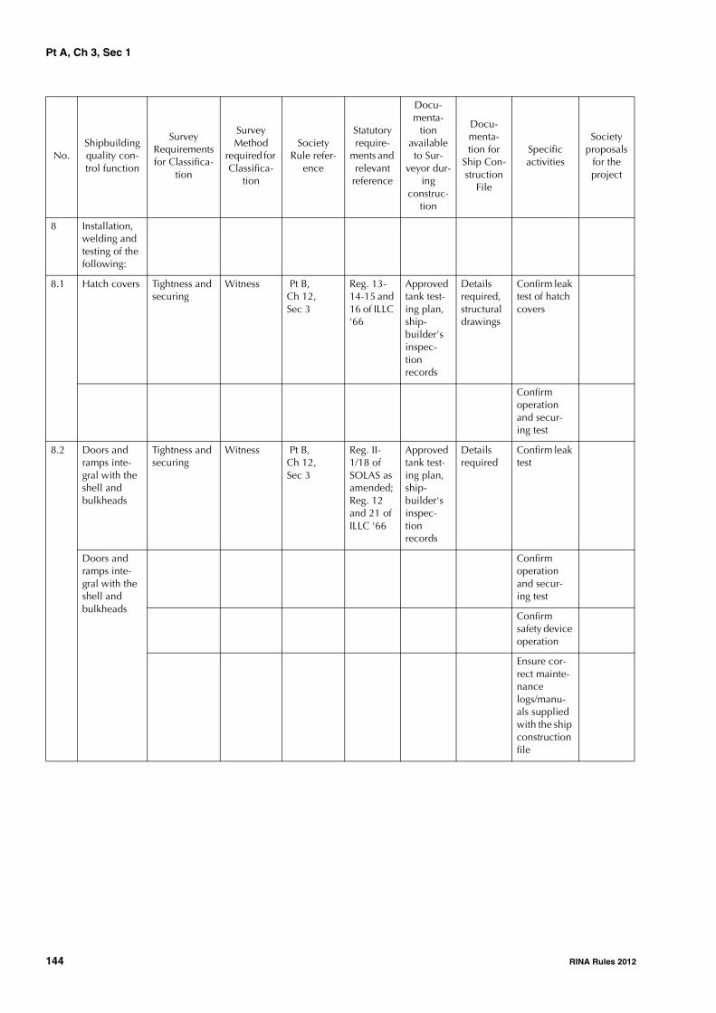
Pt A, Ch 3, Sec 1
144 RINA Rules 2012
8 Installation, welding and testing of the following:
8.1 Hatch covers Tightness and securing
Witness Pt B, Ch 12, Sec 3
Reg. 13-14-15 and 16 of ILLC '66
Approved tank test-ing plan, ship-builder's inspec-tion records
Details required, structural drawings
Confirm leak test of hatch covers
Confirm operation and secur-ing test
8.2
Doors and ramps inte-gral with the shell and bulkheads
Tightness and securing
Witness Pt B, Ch 12, Sec 3
Reg. II-1/18 of SOLAS as amended; Reg. 12 and 21 of ILLC '66
Approved tank test-ing plan, ship-builder's inspec-tion records
Details required
Confirm leak test
Doors and ramps inte-gral with the shell and bulkheads
Confirm operation and secur-ing test
Confirm safety device operation
Ensure cor-rect mainte-nance logs/manu-als supplied with the ship construction file
No.Shipbuilding quality con-trol function
Survey Requirements for Classifica-
tion
Survey Method
required for Classifica-
tion
Society Rule refer-
ence
Statutory require-
ments and relevant
reference
Docu-menta-
tion available to Sur-
veyor dur-ing
construc-tion
Docu-menta-tion for
Ship Con-struction
File
Specific activities
Society proposals
for the project

Pt A, Ch 3, Sec 1
RINA Rules 2012 145
8.3 Rudders Fitting Witness Pt B, Ch 12, Sec 3
Approved plan, ship-builder's inspec-tion records
Details required, structural drawings
Confirm alignment and mount-ing and fit-ting up to the connec-tion to the tiller
Confirm function test
Verify fitting of pintles and all securing bolts
Verify all fit-up records including all clearances maintained and placed into ship construction file
No.Shipbuilding quality con-trol function
Survey Requirements for Classifica-
tion
Survey Method
required for Classifica-
tion
Society Rule refer-
ence
Statutory require-
ments and relevant
reference
Docu-menta-
tion available to Sur-
veyor dur-ing
construc-tion
Docu-menta-tion for
Ship Con-struction
File
Specific activities
Society proposals
for the project
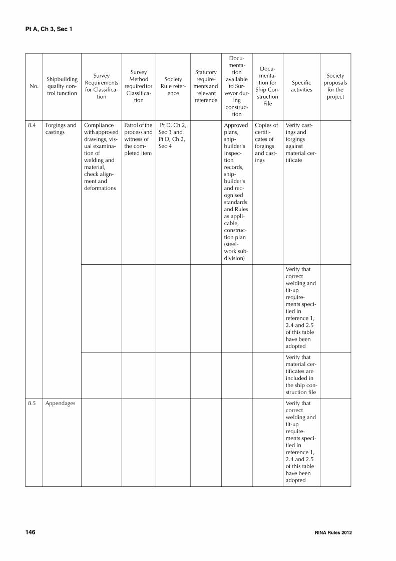
Pt A, Ch 3, Sec 1
146 RINA Rules 2012
8.4 Forgings and castings
Compliance with approved drawings, vis-ual examina-tion of welding and material, check align-ment and deformations
Patrol of the process and witness of the com-pleted item
Pt D, Ch 2, Sec 3 and Pt D, Ch 2, Sec 4
Approved plans, ship-builder's inspec-tion records, ship-builder's and rec-ognised standards and Rules as appli-cable, construc-tion plan (steel-work sub-division)
Copies of certifi-cates of forgings and cast-ings
Verify cast-ings and forgings against material cer-tificate
Verify that correct welding and fit-up require-ments speci-fied in reference 1, 2.4 and 2.5 of this table have been adopted
Verify that material cer-tificates are included in the ship con-struction file
8.5 Appendages Verify that correct welding and fit-up require-ments speci-fied in reference 1, 2.4 and 2.5 of this table have been adopted
No.Shipbuilding quality con-trol function
Survey Requirements for Classifica-
tion
Survey Method
required for Classifica-
tion
Society Rule refer-
ence
Statutory require-
ments and relevant
reference
Docu-menta-
tion available to Sur-
veyor dur-ing
construc-tion
Docu-menta-tion for
Ship Con-struction
File
Specific activities
Society proposals
for the project
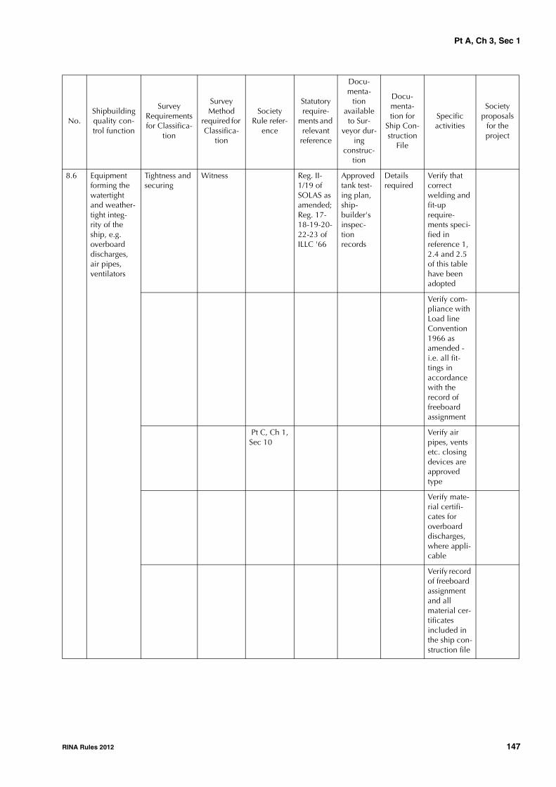
Pt A, Ch 3, Sec 1
RINA Rules 2012 147
8.6 Equipment forming the watertight and weather-tight integ-rity of the ship, e.g. overboard discharges, air pipes, ventilators
Tightness and securing
Witness Reg. II-1/19 of SOLAS as amended; Reg. 17-18-19-20-22-23 of ILLC '66
Approved tank test-ing plan, ship-builder's inspec-tion records
Details required
Verify that correct welding and fit-up require-ments speci-fied in reference 1, 2.4 and 2.5 of this table have been adopted
Verify com-pliance with Load line Convention 1966 as amended - i.e. all fit-tings in accordance with the record of freeboard assignment
Pt C, Ch 1, Sec 10
Verify air pipes, vents etc. closing devices are approved type
Verify mate-rial certifi-cates for overboard discharges, where appli-cable
Verify record of freeboard assignment and all material cer-tificates included in the ship con-struction file
No.Shipbuilding quality con-trol function
Survey Requirements for Classifica-
tion
Survey Method
required for Classifica-
tion
Society Rule refer-
ence
Statutory require-
ments and relevant
reference
Docu-menta-
tion available to Sur-
veyor dur-ing
construc-tion
Docu-menta-tion for
Ship Con-struction
File
Specific activities
Society proposals
for the project

Pt A, Ch 3, Sec 1
148 RINA Rules 2012
9 Freeboard marks and draught marks
Within allow-able toler-ances and in accordance with the free-board assign-ment
Witness Reg. 4- 5- 6- 7 and 8 of ILLC '66
Details required
Verify free-board marks in accord-ance with load line assignment
Verify draught marks in accordance with the agreed toler-ances speci-fied by the builder unless more onerous flag State require-ments
10 Principal dimensions
Within allow-able toler-ances
Review and witness
Guide for welding
Details required
Verify princi-pal dimen-sions in accordance with recog-nised stand-ards
Verify dimensions included in ship con-struction file
11 Safety Con-struction cer-tification
No outstand-ing imperfec-tions or defects
Witness Reg. 10 of SOLAS as amended
Verify that Administra-tion require-ments have been incor-porated into the hull structure
No.Shipbuilding quality con-trol function
Survey Requirements for Classifica-
tion
Survey Method
required for Classifica-
tion
Society Rule refer-
ence
Statutory require-
ments and relevant
reference
Docu-menta-
tion available to Sur-
veyor dur-ing
construc-tion
Docu-menta-tion for
Ship Con-struction
File
Specific activities
Society proposals
for the project

Pt A, Ch 3, Sec 2
RINA Rules 2012 149
SECTION 2 SURVEY FOR ASSIGNMENT OF CLASS OF A SHIP
IN SERVICE
1 Surveys required by IACS Proce-dural Requirement PR1A
1.1 Transfer to the Society's class of a ship in service classed by another QSCS Classification Society
1.1.1 General (1/7/2009)
Surveys for assignment of class may be credited as periodi-cal surveys for maintenance of class, provided that the los-ing Society is a QSCS Classification Society as defined in Ch2, Sec 1, [1.1.1]. In this case, all recommendations due forcompliance at that periodical survey are to be compliedwith.
1.1.2 Surveys (1/7/2009)
Notwithstanding the records indicating that all surveys areup-to-date, a survey for assignment of class is held by theSociety, the extent of which is based on the age of the shipand the losing Society's class status as follows:
a) Hull:
1) for ships less than 5 years of age the survey takes theform of an annual survey;
2) additionally, for ships between 5 and 10 years of agethe survey includes inspection of a representativenumber of ballast spaces;
3) additionally, for ships of 10 years of age and abovebut less than 20 years of age, the survey includesinspection of a representative number of cargospaces;
4) for ships provided with the Additional Service Fea-ture "ESP" which are 15 years of age and above butless than 20 years of age, the survey has the scope ofa class renewal survey or an intermediate survey,whichever is due next;
5) for all ships which are 20 years of age and above,the survey has the scope of a class renewal survey(this is also applicable to ships having their hullunder continuous survey);
6) in the context of applying items 4) and 5) above, ifdry-docking of the ship is not due at the time oftransfer, consideration can be given to carrying outan underwater examination in lieu of dry-docking.
7) in the context of applying items 1) to 6) above, asapplicable:
• if the class entry survey is to be credited as aperiodical survey for maintenance of class, con-sideration may be given by the Society to theacceptance of thickness measurements taken bythe losing society provided they were carried outwithin the applicable survey window of the peri-odical survey in question;
• if the class entry survey is not to be credited as aperiodical survey for maintenance of class, con-sideration may be given by the Society to theacceptance of thickness measurements taken bythe losing society provided they were carried outwithin 15 months prior to completion of theclass entry survey when it is within the scope ofa Class Renewal Survey, or within 18 monthsprior to completion of the class entry surveywhen it is within the scope of an IntermediateSurvey.
In both cases, the thickness measurements are to bereviewed by the Society for compliance with theapplicable survey requirements, and confirmatorygaugings are to be taken to the satisfaction of theSociety.
8) in the context of applying 3) to 6) above, as applica-ble, tank testing for ships over 15 years of age is notrequired to be carried out unless the survey is cred-ited as a periodical survey for maintenance of class;
9) in the context of applying 1) to 6) above, as applica-ble, compliance with IACS Unified Requirementsthat demand fulfillment at the forthcoming due peri-odical surveys (such as S26 and S27) is not requiredunless the survey is credited as a periodical surveyfor maintenance of class.
b) Machinery:
A general examination of all essential machinery is heldand includes the following:
1) examination under working conditions of fuel oilburning equipment of boilers, economisers andsteam/steam generators. The adjustment of safetyvalves of this equipment is to be verified by check-ing the records on the ship;
2) all pressure vessels;
3) insulation resistance, generator circuit-breakers,preference tripping relays and generator primemover governors are to be tested and paralleling andload sharing to be proved ( Note 1);
4) in all cases, navigating lights and indicators are to beexamined and their working and alternative sourcesof power verified;

Pt A, Ch 3, Sec 2
150 RINA Rules 2012
5) bilge pumps, emergency fire pumps and remotecontrol for oil valves, fuel oil pumps, lubricating oilpumps and forced draught fans are to be examinedunder working conditions;
6) recirculating and ice clearing arrangements, if any;
7) the main and all auxiliary machinery necessary foroperation of the ship at sea together with essentialcontrols and steering gear is to be tested underworking conditions. Alternative means of steeringare to be tested. A short sea trial is to be held at theSurveyor's discretion if the ship has been laid up fora long period;
8) initial start arrangements are to be verified;
9) in the case of oil tankers, the cargo oil system andelectrical installation in way of hazardous spaces areto be checked for compliance with the Society'sRule requirements. Where intrinsically safe equip-ment is installed, the Surveyor is to satisfy himselfthat a recognised authority has approved suchequipment. The safety devices, alarms and essentialinstruments of the inert gas system are to be verifiedand the plant generally examined to ensure that itdoes not constitute a hazard to the ship ( Note 1).
Note 1: For the transfer of class or adding class at ship's delivery,items listed in 3) and 9) may be verified by reviewing the ship'srecords.
1.2 Addition of the Society's class to a ship in service classed by another QSCS Classification Society
1.2.1 General (1/7/2009)
Surveys for assignment of class may be credited as periodi-cal surveys for maintenance of class provided that the losingSociety is a QSCS Classification Society as defined in Ch 2,Sec 1, [1.1.1]. In this case, all recommendations due forcompliance at that periodical survey are to be compliedwith.
1.2.2 Surveys for double class ships (1/7/2007)
The requirements of [1.1.2] apply.
1.2.3 Surveys for dual class ships (1/7/2007)
Notwithstanding the records indicating that all surveys areup-to-date, a survey for assignment of class is held by theSociety, the extent of which is that of an annual survey as aminimum.
1.3 Transfer to the Society's class of a ship surveyed during construction by another QSCS Classification Society at ship's delivery
1.3.1 General (1/1/2008)
A survey for assignment of class at ship's delivery is to beheld by the Society, the extent of which is that of an annualsurvey as minimum.
1.4 Addition of the Society's class to a ship surveyed during construction by another QSCS Classification Society at ship's delivery
1.4.1 General (1/1/2008)
A survey for adding the Society's class at ship's delivery is tobe held by the Society, the extent of which is that of anannual survey as minimum.
1.5 Ships of less than 100 gross tonnage
1.5.1 Surveys and documentation (1/7/2007)
For ships of less than 100 gross tonnage, special considera-tion will be given to the scope of surveys and documenta-tion to be supplied.
1.6 Ships in service not classed with a QSCS Classification Society or not classed at all
1.6.1 General (1/7/2007)
In this case, the class of the ship will be assigned upon apreliminary review of the documentation listed in [1.6.3]and subsequent satisfactory completion of the surveys, theextent and scope of which are given below.
1.6.2 Surveys (1/7/2007)
The extent and scope of the admission to class survey are tobe not less than those required at the class renewal surveyof a ship of the same age and type; in addition all otherperiodical surveys should be performed together with thoseinspections which are linked to specific service notationsand/or additional class notations and/or special installationsthe ship is provided with.
1.6.3 Documentation (1/7/2007)
As a general rule, the documentation to be supplied to theSociety is not less than the following
a) Main plans:
1) general arrangement,
2) capacity plan,
3) loading cases, calculations of still water bendingmoments, and relevant documents, particulars ofloading calculator and instruction booklet as per theSociety's requirements, according to the case,
4) stability documentation, as applicable (refer toPart B, Chapter 3).
b) Hull structure plans:
1) midship section,
2) profile and deck plan,
3) shell expansion,
4) watertight bulkheads,
5) rudder and rudder stock,
6) hatch covers.

Pt A, Ch 3, Sec 2
RINA Rules 2012 151
c) Machinery plans:
1) engine room general arrangement,
2) diagram of fuel- (transfer, service), bilge-, ballast-,lubricating oil-, cooling-, steam- and feed-, generalservice and starting compressed air piping,
3) drawings of shaft line, reduction gear and propeller,
4) drawings of boilers and air receivers,
5) drawings of steering gear,
6) torsional vibration calculations as per conditionslaid down in Pt C, Ch 1, Sec 9; such documents arerequired only for ships less than 2 years old or forolder ships the propelling system of which has beenmodified during the two years preceding the classifi-cation,
d) Electrical installation plans:
1) master plan of power distribution, lighting andemergency power circuits,
2) single line diagram of networks and switchboards,
3) location and arrangement of electrical equipment inhazardous areas.
Alternative technical data may be accepted by the Societyin lieu of specific items of the listed documentation notavailable at the time of the transfer of class.
1.6.4 Equivalence criterion (1/7/2007)Where appropriate within reasonable limits, a proven serv-ice record of satisfactory performance during a period of
adequate length may be used as a criterion of equivalence.Special consideration will be given to ships of recent con-struction.
1.6.5 Additional service and/or class notations (1/7/2007)
For installations or equipment covered by additional serviceand/or class notations, the Society will determine the docu-mentation to be submitted.
1.6.6 Other documentation (1/7/2007)
In addition, the Society may base its judgement upon docu-mentation such as certificates issued or accepted by theformer Classification Society, if any, and statutory certifi-cates issued by the flag Administration or by a recognisedorganisation on its behalf; moreover, other documentsand/or plans may be specifically required to be supplied tothe Society in individual cases.
1.7 Reassignment of class
1.7.1 Conditions for reassignment (1/7/2007)
At the request of the Owner, a ship which was previouslyclassed with the Society, subsequently withdrawn fromclass and has not been classed since may have the classreassigned subject to an admission to class survey. If appli-cable and appropriate, account may be taken of any period-ical surveys held in the former period of class with theSociety.
Pt A, Ch 3, Sec 3
152 RINA Rules 2012
SECTION 3 ANNUAL SURVEY
1 General
1.1
1.1.1 The requirements of this Section apply to annual sur-veys of all ships. The specific requirements for annual sur-veys related to service notations and additional classnotations assigned to ships are addressed in Chapter 4 andChapter 5, respectively.
1.1.2 At the time of annual surveys, the ship is to be gener-ally examined. The survey is to include a visual inspectionof the hull, equipment and machinery of the ship and sometests thereof, so far as necessary and practicable in order toverify that the ship is in a satisfactory and efficient generalcondition and is properly maintained.
1.1.3 Owners are reminded that, in compliance with therequirements in Ch 2, Sec 2, [6.4], any modification to theship’s hull, equipment and machinery affecting its classifi-cation is to be made known to the Society.
2 Hull
2.1 Scope
2.1.1 (1/7/2006)
The survey is to consist of an examination for the purpose ofensuring, as far as practicable, that the hull, hatch covers,hatch coamings, closing appliances, equipment and relatedpiping are maintained in a satisfactory condition.
2.2 Hull and hull equipment
2.2.1 (1/7/2011)
The survey is to include a general external examination andtesting, where appropriate, verifying the efficient conditionof the following items, as applicable:
• outer shell plating above the waterline, relevant shelldoors and accessible parts of the rudder(s)
• plating of freeboard deck and exposed decks, super-structures, with their openings and means of closure
• openings on exposed decks, with their coamings andtheir means of closure and securing arrangements (forcargo hatchways see [2.3])
• sidescuttles and deadlights, garbage chutes and otheropenings with their means of closure
• bulwarks, guard rails, freeing ports, gangways and life-lines, ladders
• scuppers and sanitary discharges, valves on dischargelines and their controls
• the means provided to minimise water ingress throughthe spurling pipes and chain lockers
• the arrangements for closing openings in the shell plat-ing below the freeboard deck
• ventilators, air pipes, overflow pipes and gas vent pipes,with their means of closure and flame screens, whererequired
• all automatic air pipe heads installed on exposed decks(see Note 2). This requirement is not applicable to pas-senger ships
• the special requirements for ships permitted to sail withtype "A" or type "B-minus" freeboards
• fittings and appliances for timber deck cargoes, whereapplicable
• freeboard marks on the ship’s sides
• deck equipment such as lifeboat davit foundations, bol-lards, fairleads, hawse pipes, etc., masts and associatedrigging, including lightning conductors
• equipment of chain cables for anchors, windlass, moor-ing lines and mooring winches, where required
• confirmation that the towing and mooring equipment isproperly marked with any restriction associated with itssafe operation (for ships built after 1/1/2007)
• deck fittings, their pedestals, if any, and the hull struc-tures associated with towing and mooring
• watertight bulkheads, their watertight doors and associ-ated local and remote controls, and their watertight pen-etrations
• main and auxiliary steering arrangements, includingtheir associated equipment and control systems, andmanoeuvring gear
• accessible cargo holds, in particular in areas likely to bedamaged by cargo handling
• confirmation that the drainage from enclosed cargospaces situated on the freeboard deck is satisfactory
• engine room and other dry spaces
• where fitted, helicopter deck and its supporting struc-ture, safety net and arrangements for the prevention ofsliding

Pt A, Ch 3, Sec 3
RINA Rules 2012 153
• availability of loading manual or, where required, elec-tronic loading instrument, including standard test
• availability of approved stability documentation.
• accuracy of the shipboard computer for stability calcu-lations (see Note 3).
Note 1: Due attention is also to be given to fuel oil piping passingthrough ballast tanks, which is to be pressure tested where doubtsarise.
Note 2: Air pipe heads installed on exposed decks are thoseextending above the freeboard deck or superstructure decks.
Note 3: It is the responsibility of the ship's Master to check theaccuracy of the shipboard computer for stability calculations ateach annual survey by applying at least one approved test condi-tion (see Pt B, Ch 11, Sec 2, [4.5]). If a Surveyor of the Society isnot present for the computer check, a copy of the test conditionresults obtained by the computer check is to be retained on boardas documentation of satisfactory testing for the Surveyor's verifica-tion. The testing procedure is to be carried out in accordance withPt B, Ch 11, Sec 2, [4.5.9]
2.3 Cargo hatch covers and coamings, weather decks and ship side plating above the waterline
2.3.1 (1/7/2006)
The Owner or his representative is to declare to the attend-ing Surveyor that no changes have been made to the hatchcovers, hatch coamings and their securing and sealingdevices without prior approval of the Society.
The survey of hatch covers and coamings is to include:
a) when fitted with portable covers, or wooden or steelpontoons, checking of the satisfactory condition of:
• wooden covers and portable beams, carriers orsockets for the portable beams, and their securingdevices
• steel pontoons
• tarpaulins
• cleats, battens and wedges
• hatch securing bars and their securing devices
• loading pads/bars and the side plate edge
• guide plates and chocks
• compression bars, drainage channels and drainpipes (if any)
b) when fitted with mechanically operated steel covers,checking of the satisfactory condition of:
• hatch covers
• tightness devices of longitudinal, transverse andintermediate cross junctions (gaskets, gasket lips,
compression bars, drainage channels and, if any,drain pipes)
• clamping devices, retaining bars, cleating • chain or rope pulleys • guides • guide rails and track wheels • stoppers, etc. • wires, chains, gypsies, tensioning devices • hydraulic system essential to closing and securing • safety locks and retaining devices
c) checking of the satisfactory condition of hatch coamingplating and its stiffeners
d) random checking of the satisfactory operation ofmechanically operated hatch covers is to be madeincluding:• stowage and securing in open condition;• proper fit and efficiency of sealing in closed condi-
tion;• operational testing of hydraulic and power compo-
nents, wires, chains and link drives.
2.3.2 (1/7/2006)Examination of the weld connection between air pipes anddeck plating.
2.3.3 (1/7/2006)External examination of all air pipe heads installed onexposed decks.
2.3.4 (1/7/2006)Examination of flame screens on vents to all bunker tanks.
2.3.5 (1/7/2006)Examination of ventilators, including closing devices, if any.
2.4 Suspect areas2.4.1 (1/7/2006)Suspect areas identified at previous surveys are to be exam-ined. Thickness measurements are to be taken of the areasof substantial corrosion and the extent of thickness meas-urements is to be increased to determine the extension ofareas of substantial corrosion. Sec 5, Tab 2 may be used asguidance for these additional thickness measurements.These extended thickness measurements are to be carriedout before the annual survey is credited as completed.Note 1: These requirements are not applicable to cargo tanks of oiltankers, chemical tankers and double hull oil tankers, surveyed inaccordance with the requirements given in Ch 4, Sec 3, Ch 4,Sec 4 and Ch 4, Sec 5, respectively.
2.5 Ballast tanks2.5.1 (1/7/2006)Examination of ballast tanks when required as a conse-quence of the results of the class renewal survey and inter-mediate survey is to be carried out. When considerednecessary by the Surveyor, or where extensive corrosionexists, thickness measurement is to be carried out. If theresults of these thickness measurements indicate that sub-stantial corrosion is found, then the extent of thicknessmeasurements is to be increased to determine the extensionof areas of substantial corrosion. Sec 5, Tab 2 may be used

Pt A, Ch 3, Sec 3
154 RINA Rules 2012
as guidance for these additional measurements. Theseextended thickness measurements are to be carried outbefore the annual survey is credited as completed.
2.6 Additional requirements for single hold cargo ships (see Note 1 to [1.1.1] of Ch 4, Sec 8)
2.6.1 (1/1/2009)
For ships complying with the requirements of SOLAS II-1/23-3 (effective from 1 January 2007 to 31 December2008) and II-1/25 (effective from 1 January 2009) for holdwater level detectors (see Note 1), the annual survey is toinclude an examination and a test, at random, of the wateringress detection system and of their alarms.
Note 1: This survey requirement is to be fulfilled at annual surveyscarried out after the ship has been made compliant with therequirements of SOLAS regulations II-1/23-3 or II-1/25, as applica-ble (see above) and commenced on or after 1 July 2007.
3 Machinery and systems
3.1 General machinery installations
3.1.1 (1/7/2007)
The survey of general machinery installations is to cover thefollowing items:
• general examination of machinery and boiler spaceswith particular attention to the fire and explosion haz-ards
• general examination of the machinery, steam, hydrau-lic, pneumatic and other systems and their associatedfittings, for confirmation of their proper maintenance
• testing of the means of communication and order trans-mission between the navigating bridge and the machin-ery control positions and other control stations
• confirmation that the rudder angle indicator on thebridge is in working order
• examination, as far as practicable, of the bilge pumpingsystems and bilge wells, including operation of thepumps, remote reach rods and level alarms, where fitted
• visual examination of the condition of any expansionjoints in sea water systems
• external examination of pressure vessels other than boil-ers and their appurtenances, including safety devices,foundations, controls, relieving gear, high pressure pip-ing, insulation and gauges
• visual examination of mechanical components used forcooling and maintaining an ambient temperature lowerthan 45°C (see Pt C, Ch 2, Sec 2, [1.2.2]).
3.1.2 (1/1/2007)
When the ship is equipped with a refrigerating plant(whether or not covered by an additional class notation),the annual survey is to include the external examination of:
• pressure vessels of the installation to the same extent asindicated in [3.1.1]
• refrigerant piping, as far as practicable
• for refrigerating machinery spaces using ammonia asrefrigerant:
- ventilation system including functional test
- bilge system including functional test
- electrical equipment, confirming its proper mainte-nance
- gas detection system
- breathing apparatus and protective clothing.
3.1.3 When the ship is equipped with thruster installa-tions, the annual survey is to include:
• an external examination of the machinery installation
• an operating test of the complete installation.
3.2 Boilers
3.2.1 For main and auxiliary boilers, the annual surveyconsists of an external examination of boilers and theirappurtenances, including safety devices, foundations, con-trols, relieving, high pressure and steam escape piping,insulation and gauges.
3.2.2 For thermal oil heaters, a functional test while inoperation is to be carried out, during which the followingitems are checked:
• the heater for detection of leakages
• the condition of the insulation
• the operation of indication, control and safety devices
• the condition of remote controls for shut-off and dis-charge valves
A satisfactory analysis of the quality of oil is to be madeavailable to the Surveyor.
3.2.3 For exhaust gas thermal oil heaters, in addition to therequirements of [3.2.2], a visual examination and a tight-ness testing to the working pressure of the heater tubes areto be carried out.
3.3 Electrical machinery and equipment
3.3.1 (1/7/2004)
The survey of electrical machinery and equipment is tocover the following items:
• general examination, visually and in operation, as feasi-ble, of the electrical installations for power and lighting,in particular main and emergency generators, electricmotors, batteries, switchboards, switchgears, cables andcircuit protective devices, indicators of electrical insula-tion and automatic starting, where provided, of emer-gency sources of power
• checking, as far as practicable, the operation of emer-gency sources of power and, where they are automatic,also including the automatic mode.
3.3.2 (1/7/2007)
The survey is also to cover electrical components used forcooling and maintaining an ambient temperature lowerthan 45°C (see Pt C, Ch 2, Sec 2, [1.2.2]).

Pt A, Ch 3, Sec 3
RINA Rules 2012 155
3.3.3 The survey is also to cover the bridge control of pro-pulsion machinery, and related arrangements (alarms andsafety devices), when fitted.The survey of an automated installation covered by an addi-tional class notation is detailed in Chapter 5.
3.4 Fire protection, detection and extinction3.4.1 (1/1/2007)The survey of fire prevention includes:• the examination, as far as practicable, and testing, as
feasible and at random, of the fire and/or smoke detec-tion systems
• the examination of arrangements for gaseous fuel fordomestic purposes, such as movable cooking appli-ances, the so-called "flambé carte".
3.4.2 (1/1/2007)The survey requirements for fixed low pressure CO2 fire-extinguishing systems fitted on board include the externalexamination of receivers of CO2 and their accessories andthe removal of insulation for insulated CO2 containers.

Pt A, Ch 3, Sec 4
156 RINA Rules 2012
SECTION 4 INTERMEDIATE SURVEY
1 General
1.1
1.1.1 The requirements of this Section apply to intermedi-ate surveys of all ships. The specific requirements for inter-mediate surveys related to service notations and additionalclass notations assigned to ships are addressed in Chapter 4and Chapter 5, respectively.
1.1.2 The intermediate survey is to include examinationand checks on a sufficiently extensive part of the structureto show that the structures of the ship are in satisfactorycondition so that the ship is expected to operate until theend of the current period of class, provided that the ship isproperly maintained and other surveys for maintenance ofclass are duly carried out during this period.
1.1.3 (1/7/2006)
A survey-planning meeting is to be held prior to the com-mencement of the survey.
2 Hull
2.1
2.1.1 (1/7/2010)
The scope of the intermediate survey includes the followingrequirements:
a) for ships between 5 and 10 years of age, a general,internal examination of representative ballast tanks. Ifthere is no hard protective coating, or soft or semi-hard
coating, or poor coating condition, the examination isto be extended to other ballast spaces of the same type;
b) for ships over 10 years of age, a general, internal exami-nation of all ballast tanks.
If considered necessary by the Surveyor, thickness measure-ments may be required.
2.1.2 (1/7/2006)If such examinations reveal no visible structural defects, theexamination may be limited to verification that the corro-sion prevention system remains effective.
2.1.3 (1/7/2010)For ballast tanks, excluding double bottom ballast tanks, ifthere is no hard protective coating, or soft or semi-hardcoating, or poor coating condition and it is not renewed,the tanks in question are to be internally examined atannual surveys.
2.1.4 (1/7/2010)When such conditions are found in double bottom ballasttanks, the tanks in question may be internally examined atannual surveys.
2.1.5 (1/7/2006)In the case of dry cargo ships over 15 years of age, otherthan bulk carriers subject to the requirements of Ch 4, Sec 2or Ch 4, Sec 9 as applicable or general dry cargo ships sub-ject to the requirements of Ch 4, Sec 8, an internal exami-nation of selected cargo holds is to be carried out.
2.1.6 (1/1/2012)In the case of ships over 10 years of age, other than shipsengaged in the carriage of dry cargoes only or ships subjectto the requirements of Ch 4, Sec 3, Ch 4, Sec 4, Ch 4, Sec 5or Ch 4, Sec 6, an internal examination of selected cargospaces is to be carried out.

Pt A, Ch 3, Sec 4
RINA Rules 2012 157
Table 1 : Intermediate survey of hull (all ships) (1/7/2006)
ITEMAge of ship (in years at time of intermediate survey)
5 < age ≤ 10 10 < age ≤ 15 age > 15
SALT WATER BALLAST SPACES Representative spaces inter-nally examinedThickness measurements, if considered necessary by the Surveyor
All spaces internally examined Thickness measurements, if considered necessary by the Surveyor
See (1) (2) (3) See (1) (3)
CARGO HOLDS (dry cargo ships) Selected cargo holds inter-nally examined
CARGO TANKS (non-ESP tankers) Selected cargo tanks inter-nally examined
(1) If such examinations reveal no visible structural defects, the examination may be limited to verification that the corrosion pre-vention system remains effective.
(2) If there is no hard protective coating, or soft coating, or poor coating condition, the examination is to be extended to other ballast spaces of the same type.
(3) For spaces used for water ballast, excluding double bottom tanks, if there is no hard protective coating, or soft coating, or poor coating condition and it is not renewed, the spaces in question are to be internally examined at annual surveys. When such conditions are found in water ballast double bottom tanks, the spaces in question may be internally examined at annual sur-veys.
Note 1: Due attention is also to be given to fuel oil piping passing through ballast tanks, which is to be pressure tested should doubts arise.

Pt A, Ch 3, Sec 5
158 RINA Rules 2012
SECTION 5 CLASS RENEWAL SURVEY
1 General
1.1
1.1.1 The requirements of this Section apply to classrenewal surveys of all ships. The specific requirements forclass renewal surveys related to service notations and addi-tional class notations assigned to ships are addressed inChapter 4 and Chapter 5, respectively.
1.1.2 (1/7/2006)
The class renewal survey is to include examination, testsand checks to show that the hull structures, main and auxil-iary machinery, systems, equipment and related piping, asrequired in [2.2.8], are in satisfactory condition or restoredto such condition as to allow the ship to operate for the newperiod of class to be assigned, provided that the ship isproperly maintained and operated and other surveys formaintenance of class are duly carried out during thisperiod.
The examinations of the hull are to be supplemented bythickness measurements and testing as required in [2.5.1]and [2.2.8], to ensure that the structural integrity remainseffective. The aim of the examination is to discover substan-tial corrosion, significant deformation, fractures, damagesor other structural deterioration.
1.1.3 The Owner is to provide the necessary facilities toenable this class renewal survey. The conditions for surveyas detailed in Ch 2, Sec 2, [2.5] to Ch 2, Sec 2, [2.7] are tobe met.
1.1.4 When the ship is under the continuous survey sys-tem for machinery and/or hull, the scope of the classrenewal survey as described in this Section is carried out ona continuous basis over the period of class according to theprocedure laid down in Ch 2, Sec 2, [4.3].
When the machinery installation is surveyed under thePlanned Maintenance System, a specific program of surveyreplaces the scope of the class renewal survey of machineryand systems as laid down in [3] below, according to theprocedure laid down in Ch 2, Sec 2, [4.4].
1.1.5 (1/7/2006)
A survey-planning meeting is to be held prior to the com-mencement of the survey.
2 Hull and hull equipment
2.1 Bottom survey
2.1.1 (1/7/2001)
The class renewal survey is to include a bottom survey aslaid down in Sec 6, [2.2].
2.2 Decks, hatch covers and equipment
2.2.1 Decks are to be examined, particular attention beinggiven to the areas where stress concentration or increasedcorrosion are likely to develop, such as hatch corners andother discontinuities of structure.
Deck erections such as hatch coamings, deckhouses andsuperstructures are to be examined.
The sheathing of wood-sheathed steel decks may beremoved, at the Surveyor’s discretion, in the case of doubtas to the condition of plating underneath.
Due attention is to be given to the examination in way ofend and side openings and related shell and inner doors.
2.2.2 (1/7/2006)
The survey of hatch covers and coamings is to include:
• a thorough inspection of the items listed in Sec 3, [2.3],including close-up survey of hatch cover plating andhatch coaming plating
• checking of the satisfactory operation of all mechani-cally operated hatch covers including stowage andsecuring in open condition, proper fit, locking and effi-ciency of sealing in closed position, operational testingof hydraulic and power components, wires, chains andlink drives
• checking of the effectiveness of sealing arrangements ofall hatch covers by means of hose testing or equivalent
• thickness measurements of coaming and attached stiff-eners, hatch cover plating and stiffeners (see Tab 2).
2.2.3 (1/7/2007)
The survey of hull equipment is to cover the followingpoints:
• windlass and chain stoppers, with disassembly asdeemed necessary to verify the condition of the equip-ment and control and safety devices, hawse pipes
• steering arrangements, including steering gear, controland indication devices, operational tests and disassem-bly as deemed necessary; in the case of chain and rodgears, chains, rods, sheaves, pins and rollers are to beexamined for wear
• connection of masts and standing rigging to the hullstructure as well as condition of structure underneath
• deck fittings, their pedestals, if any, and the hull struc-tures associated with towing and mooring, with disas-sembly where applicable and as deemed necessary.

Pt A, Ch 3, Sec 5
RINA Rules 2012 159
2.2.4 (1/7/2007)
Piping systems outside tanks and compartments are to bevisually examined and pressure tested as necessary, as perthe requirements laid down for the class renewal survey ofmachinery and systems; see [3.5].
Ventilators, air pipes, overflow pipes and gas vent pipes,with their means of closure and flame screens, are to beopened up as necessary for the internal examination.
2.2.5 (1/7/2003)
For all ships except for passenger ships, automatic air pipeheads are to be completely examined (both internally andexternally ) as indicated in Tab 4.
For designs where the inner parts cannot be properlyinspected from outside, this is to include removal of thehead from the air pipe. Particular attention is to be paid tothe condition of the zinc coating in heads constructed fromgalvanised steel.
2.2.6 (1/7/2003)
The anchors and chain cables are to be ranged and exam-ined, and the required complement and condition verified.The chain locker, holdfasts, hawse pipes and chain stoppersare to be examined and pumping arrangements of the chainlocker tested. At class renewal surveys of ships more than 5years of age, chain cables are to gauged and renewed incases where their mean diameter is worn below the limitsallowed.
2.2.7 (1/7/2005)
The accuracy of the shipboard computer for stability calcu-lations is to be checked by applying all approved test load-ing conditions. The testing procedure is to be carried out inaccordance with Pt B, Ch 11, Sec 2, [4.5.9].
2.2.8 (1/7/2006)
All bilge and ballast piping systems are to be examined andoperationally tested to working pressure to the attendingSurveyor's satisfaction to ensure that tightness and condi-tion remain satisfactory.
2.3 Holds and other dry compartments
2.3.1 (1/7/2006)
All spaces including holds and their 'tweendecks where fit-ted, double bottom, deep, ballast, peak and cargo tanks,pump rooms, pipe tunnels, duct keels, machinery spaces,dry spaces, cofferdams and voids are to be internally exam-ined, including the plating and framing, bilges and drainwells, sounding, venting, pumping and drainage arrange-ments. Internal examination of fuel oil, lube oil and freshwater tanks is to be carried out in accordance with Tab 5.
2.3.2 (1/1/2003)
Machinery and boiler spaces, pump rooms and otherspaces containing machinery are to be internally examined,ascertaining the condition of the structure. Particular atten-tion is to be given to tank tops, shell plating in way of tanktops, brackets connecting side shell frames and tank tops,and bulkheads in way of tank tops and bilge wells. Particu-lar attention is also to be given to the sea suctions, sea water
cooling pipes and overboard discharge valves and theirconnections to the shell plating. Where wastage is evidentor suspected, thickness measurements are to be carried out,and renewals or repairs effected when wastage exceedsallowable limits.
Piping systems inside these spaces are to be dealt withaccording to [3.5].
2.3.3 Chain lockers are to be internally examined, whilethe anchor chains are ranged as required for the bottom sur-vey in dry condition (see [2.2.6]). The pumping arrange-ment of the chain lockers is to be tested.
2.4 Tanks
2.4.1 (1/7/2006)
The type and number of tanks to be internally examined ateach class renewal survey are detailed in Tab 1 for cargoand water ballast tanks and Tab 5 for fuel oil, lubricating oiland fresh water tanks, according to the age of the ship.
This internal examination is to ascertain the condition of thestructure, bilges and drain wells, sounding, venting, pump-ing and drainage arrangements, including piping systemsand their fittings. Due attention is to be given to plating ordouble plates below the lower end of sounding and suctionpipes.
Where wastage is evident or suspected, thickness measure-ments are to be carried out, and renewals or repairs effectedwhen wastage exceeds allowable limits.
Where the inner surface of the tanks is covered with cementor other compositions, the removal of coverings may bewaived provided they are examined, found sound andadhering satisfactorily to the steel structures.
Note 1: For examination of independent (non-structural) tanks,refer to [3.5.9].
Note 2: Due attention is also to be given to fuel oil piping passingthrough ballast tanks, which is to be pressure tested when the shipis more than 10 years old.
2.4.2 (1/7/2010)
Where provided, the condition of corrosion prevention sys-tems of ballast tanks is to be examined. For ballast tanksexcluding double bottom tanks, where a hard protectivecoating is found in poor condition and it is not renewed,where soft or semi-hard coating has been applied, or wherea hard protective coating has not been applied since thetime of construction, the tanks in question are to be exam-ined at annual surveys. Thickness measurements are to becarried out as deemed necessary by the Surveyor.
When such breakdown of hard protective coating is foundin double bottom ballast tanks and it is not renewed, wherea soft or semi-hard coating has been applied, or where ahard protective coating has not been applied since the timeof construction, the tanks in question may be examined atannual surveys. When considered necessary by the Sur-veyor, or where extensive corrosion exists, thickness meas-urements are to be carried out.
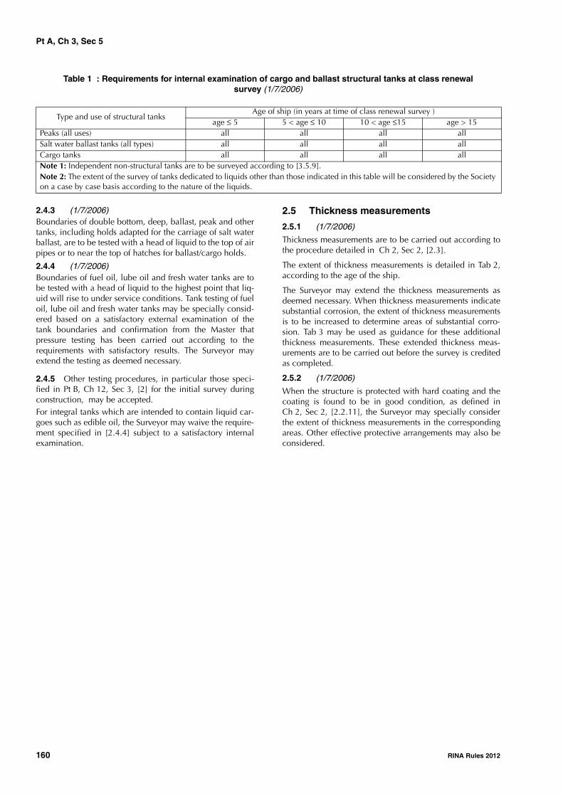
Pt A, Ch 3, Sec 5
160 RINA Rules 2012
Table 1 : Requirements for internal examination of cargo and ballast structural tanks at class renewal survey (1/7/2006)
2.4.3 (1/7/2006)Boundaries of double bottom, deep, ballast, peak and othertanks, including holds adapted for the carriage of salt waterballast, are to be tested with a head of liquid to the top of airpipes or to near the top of hatches for ballast/cargo holds.
2.4.4 (1/7/2006)Boundaries of fuel oil, lube oil and fresh water tanks are tobe tested with a head of liquid to the highest point that liq-uid will rise to under service conditions. Tank testing of fueloil, lube oil and fresh water tanks may be specially consid-ered based on a satisfactory external examination of thetank boundaries and confirmation from the Master thatpressure testing has been carried out according to therequirements with satisfactory results. The Surveyor mayextend the testing as deemed necessary.
2.4.5 Other testing procedures, in particular those speci-fied in Pt B, Ch 12, Sec 3, [2] for the initial survey duringconstruction, may be accepted.For integral tanks which are intended to contain liquid car-goes such as edible oil, the Surveyor may waive the require-ment specified in [2.4.4] subject to a satisfactory internalexamination.
2.5 Thickness measurements
2.5.1 (1/7/2006)
Thickness measurements are to be carried out according tothe procedure detailed in Ch 2, Sec 2, [2.3].
The extent of thickness measurements is detailed in Tab 2,according to the age of the ship.
The Surveyor may extend the thickness measurements asdeemed necessary. When thickness measurements indicatesubstantial corrosion, the extent of thickness measurementsis to be increased to determine areas of substantial corro-sion. Tab 3 may be used as guidance for these additionalthickness measurements. These extended thickness meas-urements are to be carried out before the survey is creditedas completed.
2.5.2 (1/7/2006)
When the structure is protected with hard coating and thecoating is found to be in good condition, as defined inCh 2, Sec 2, [2.2.11], the Surveyor may specially considerthe extent of thickness measurements in the correspondingareas. Other effective protective arrangements may also beconsidered.
Type and use of structural tanksAge of ship (in years at time of class renewal survey )
age ≤ 5 5 < age ≤ 10 10 < age ≤15 age > 15Peaks (all uses) all all all allSalt water ballast tanks (all types) all all all allCargo tanks all all all allNote 1: Independent non-structural tanks are to be surveyed according to [3.5.9].Note 2: The extent of the survey of tanks dedicated to liquids other than those indicated in this table will be considered by the Society on a case by case basis according to the nature of the liquids.
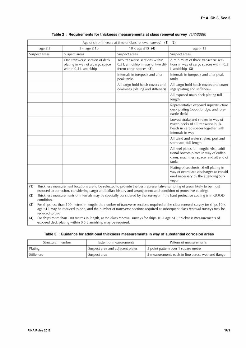
Pt A, Ch 3, Sec 5
RINA Rules 2012 161
Table 2 : Requirements for thickness measurements at class renewal survey (1/7/2006)
Table 3 : Guidance for additional thickness measurements in way of substantial corrosion areas
Age of ship (in years at time of class renewal survey) (1) (2)
age ≤ 5 5 < age ≤ 10 10 < age ≤15 (4) age > 15
Suspect areas Suspect areas Suspect areas Suspect areas
One transverse section of deck plating in way of a cargo space within 0,5 L amidship
Two transverse sections within 0,5 L amidship in way of two dif-ferent cargo spaces (3)
A minimum of three transverse sec-tions in way of cargo spaces within 0,5 L amidship (3)
Internals in forepeak and after peak tanks
Internals in forepeak and after peak tanks
All cargo hold hatch covers and coamings (plating and stiffeners)
All cargo hold hatch covers and coam-ings (plating and stiffeners)
All exposed main deck plating full length
Representative exposed superstructure deck plating (poop, bridge, and fore-castle deck)
Lowest strake and strakes in way of tween decks of all transverse bulk-heads in cargo spaces together with internals in way
All wind and water strakes, port and starboard, full length
All keel plates full length. Also, addi-tional bottom plates in way of coffer-dams, machinery space, and aft end of tanks
Plating of seachests. Shell plating in way of overboard discharges as consid-ered necessary by the attending Sur-veyor
(1) Thickness measurement locations are to be selected to provide the best representative sampling of areas likely to be most exposed to corrosion, considering cargo and ballast history and arrangement and condition of protective coatings.
(2) Thickness measurements of internals may be specially considered by the Surveyor if the hard protective coating is in GOOD condition.
(3) For ships less than 100 metres in length, the number of transverse sections required at the class renewal survey for ships 10 < age ≤15 may be reduced to one, and the number of transverse sections required at subsequent class renewal surveys may be reduced to two
(4) For ships more than 100 metres in length, at the class renewal surveys for ships 10 < age ≤15, thickness measurements of exposed deck plating within 0,5 L amidship may be required.
Structural member Extent of measurements Pattern of measurements
Plating Suspect area and adjacent plates 5 point pattern over 1 square metre
Stiffeners Suspect area 3 measurements each in line across web and flange

Pt A, Ch 3, Sec 5
162 RINA Rules 2012
Table 4 : Survey requirements for automatic air pipe heads at class renewal surveys (1/7/2003)
Table 5 : Requirements for internal examination of fuel oil, lubricating oil and fresh water tanks at class renewal survey (1/7/2006)
2.6 Additional requirements for single hold cargo ships (see Note 2 to [1.1.1] of Ch 4, Sec 8)
2.6.1 (1/1/2009)For ships complying with the requirements of SOLAS II-1/23-3 (effective from 1 January 2007 to 31 December2008) and II-1/25 (effective from 1 January 2009) for holdwater level detectors (see Note 1), the class renewal surveyis to include an examination and a test of the water ingressdetection system and their alarms.
Note 1: This survey requirement is to be fulfilled at class renewalsurveys carried out after the ship has been made compliant with therequirements of SOLAS regulations II-1/23-3 or II-1/25, as applica-ble (see above) and commenced on or after 1 July 2007.
3 Machinery and systems
3.1 General
3.1.1 The survey items listed below are to be covered tothe satisfaction of the Surveyor. However, other surveyalternatives deemed equivalent by the Surveyor in relation
to the characteristics and general condition of the ship con-cerned may also be accepted.
Note 1: Attention is drawn to the requirement Ch 2, Sec 2, [2.5.1]regarding safe execution of surveys, in particular as regards healthhazards related to asbestos.
3.1.2 Machinery verification runs (1/1/2001)
At the time of dry-docking, a dock trial is to be carried outto attending Surveyors’ satisfaction to confirm satisfactoryoperation of main and auxiliary machinery. If significantrepairs are carried out to main or auxiliary machinery orsteering gear, consideration should be given to a sea trial toattending Surveyors’ satisfaction.
3.2 Main and auxiliary engines and turbines
3.2.1 GeneralDepending on the type of machinery, the following partsare to be opened up as necessary for inspection. Parts andcomponents are to be pressure tested as appropriate or asdeemed necessary by the Surveyor. A working test is also tobe carried out, including testing of alarms and safetydevices.
Age of ship (in years at time of class renewal survey due date)
age ≤ 5 5 < age ≤ 10 age >10
- Two air pipe heads, one port and one starboard, located on the exposed decks in the forward 0,25 L, preferably air pipes serving ballast tanks.
- Two air pipe heads, one port and one starboard, on the exposed decks, serving spaces aft of 0,25 L, preferably air pipes serving ballast tanks.
- All air pipe heads located on the exposed decks in the forward 0,25 L.
- At least 20%of air pipe heads on the exposed decks serving spaces aft of 0,25 L, preferably air pipes serving ballast tanks.
- All air pipe heads located on the exposed decks.
See (1) and (2) See (1) and (2) See (3)
(1) The selection of air pipe heads to be inspected is left to the attending Surveyor.(2) According to the results of this inspection, the Surveyor may require the inspection of other heads located on the exposed
decks.(3) Exemption may be considered for air pipe heads where there is substantiated evidence of replacement within the previous five
years.
Type and use of structural tanksAge of ship (in years at time of class renewal survey )
age ≤ 5 5 < age ≤ 10 10 < age ≤15 age > 15Fuel oil - diesel oil tanks (engine room) none none one oneFuel oil - diesel oil tanks (cargo length area)
none one two half, minimum two
Lubricating oil tanks none none none oneFresh water tanks none one all allNote 1: These requirements apply to tanks of integral (structural) type.Note 2: If a selection of tanks is accepted to be examined, then different tanks are to be examined at each class renewal survey, on a rotational basis. Note 3: Peak tanks (all uses) are subject to internal examination at each class renewal survey.Note 4: At class renewal survey no. 3 and subsequent (ships older than 10 years), one deep tank for fuel oil in the cargo length area is to be included, if fitted.
Pt A, Ch 3, Sec 5
RINA Rules 2012 163
3.2.2 Internal combustion engines
a) Columns and entablature
b) Cylinders with their liners, cylinder covers (togetherwith valves and valve gear), pistons with their rods,crossheads, slippers and guides (or gudgeon pins), con-necting rods (with their top and bottom end bearings),control gear, driven scavenge pumps, driven air com-pressors, driven fuel pumps, supercharging blowers, fuelinjection pumps, turning gear, etc.
c) Crankshafts (together with their main bearings)
d) Reverse gear, reduction gear and clutches, if fitted.
3.2.3 Steam turbines
a) Condensers and their cooling water and condensateextraction pumps
b) Casings and rotors (including their blading), impulsewheels (including guide blading and diaphragms), noz-zles and nozzle boxes, journals and bearings, dummypistons, labyrinths, external glands, etc.
c) Shafts, including their flexible couplings.
Where the propulsion steam turbines are of a well-knowntype, and fitted with rotor position indicators and vibrationindicators of an approved type, as well as measuring equip-ment of steam pressure at proper locations along the steamflow, and the arrangements for change-over in the event ofemergency operation of the plant are readily operable, thefirst class renewal survey may be limited to the examinationof rotor bearings, thrust bearings and flexible couplings,provided the Surveyor is satisfied from operation servicerecords and power trials subsequent to the survey, that theturbine plant is in good working condition.
3.2.4 Gas turbines
a) Casings, rotors and disks, impellers and blading of allturbines and compressors, combustion chambers, burn-ers, heat exchangers, gas piping, compressed air pipingwith fittings, starting and reverse arrangements
b) Shafts and their flexible couplings.
3.2.5 Electric propulsionWhere the propulsion machinery consists of an electricalsystem, the propulsion motors, generators, cables and allancillary electrical gear, exciters and ventilating plant(including coolers) associated therewith are to be examinedand the insulation resistance to earth tested. Due attentionis to be given to windings, commutations and sliprings. Theoperation of protective gear and alarm devices is to bechecked, as far as practicable. Interlocks intended to pre-vent unsafe operations or unauthorised access are to bechecked to verify that they are functioning correctly.
3.2.6 Thruster installationsWhen the ship is equipped with thruster installations, theclass renewal survey is also to include:
• a thorough examination of the machinery and electricalinstallation, as applicable
• an external examination of the propulsive part of theinstallation to be carried out at the dry dock survey dueas part of the class renewal survey. During this examina-tion other checks such as clearance readings, tightness
of hub and blade sealing for controllable pitch propel-lers are to be verified. Locking arrangements for bolts, iffitted, are to be checked. Results of lubricating oil analy-sis to detect possible deterioration of internal gears andbearings or the presence of water are to be confirmed asacceptable. The Manufacturer’s requirements may betaken into account. Dismantling of the assembly for theexamination of internal parts may be required if theforegoing checks are not satisfactory
• a running test of the system under operating conditions.
3.3 Reduction gears, main thrust and inter-mediate shaft(s)
3.3.1 Reduction gears complete with all wheels, pinions,shafts, couplings, bearings and gear teeth, including incor-porated clutch arrangements, are to be opened up, asdeemed necessary by the Surveyor, for visual inspection.For complicated assemblies, gears and roller bearings maybe inspected without dismantling.
3.3.2 All shafts, thrust blocks and bearings are to be exam-ined.
3.4 Pumps and other machinery items
3.4.1 GeneralThe items listed in [3.4.2] are to be opened up, as deemednecessary by the Surveyor, for visual inspection. Their partsand components are to be pressure tested as appropriateand considered necessary by the Surveyor. A working test isalso to be carried out, including testing of alarms and safetydevices if deemed necessary by the Surveyor.
3.4.2 Items to be surveyed (1/7/2007)
a) Air compressors with their intercoolers, filters and/or oilseparators and safety devices
b) Heat exchangers, ventilation fans for boilers and otherequipment used for essential services
c) Piston pumps and centrifugal pumps for sea water, bilgeand salt water ballast
d) Screw pumps, gear pumps and centrifugal pumps otherthan those listed in c) above (opening up is not required)
e) Mechanical components used for cooling and maintain-ing an ambient temperature lower than 45°C (see Pt C,Ch 2, Sec 2, [1.2.2]).
3.5 Systems in machinery spaces
3.5.1 Valves, cocks and strainers of the bilge and ballastsystems are to be opened up, thoroughly or partly asdeemed necessary by the Surveyor, for visual inspection,and, together with the piping and safety devices, examinedand tested under working conditions.
3.5.2 The fuel oil, lubricating oil, hydraulic oil, thermaloil, and feed and cooling water systems, together with pres-sure filters, heaters and coolers used for essential services,are to be opened up and examined or tested, as considerednecessary by the Surveyor. Safety devices for the foregoingitems are to be examined.

Pt A, Ch 3, Sec 5
164 RINA Rules 2012
3.5.3 The compressed air system together with its valves,fittings and safety devices is to be examined, as considerednecessary by the Surveyor.
3.5.4 (1/7/2006)
Compressed air receivers and other pressure vessels foressential services are to be cleaned internally and examinedinternally and externally. Where the above receivers or ves-sels cannot be examined internally, they are to be hydrostat-ically tested to 1,5 times the working pressure. Their fittings,valves and safety devices are to be opened up, as deemednecessary by the Surveyor, for visual inspection and pres-sure tested as appropriate.
3.5.5 Steel pipes for superheated steam having a tempera-ture of the steam at the superheater outlet exceeding 450°Care to be examined and tested in accordance with [3.5.7] to[3.5.8] at each class renewal survey.
3.5.6 Steel pipes for saturated steam or superheated steamhaving a temperature of the steam at the superheater outletnot exceeding 450°C are to be examined and tested inaccordance with [3.5.7] to [3.5.8] at each class renewalsurvey for ships over 5 years of age. When the ship is 5years of age or less, the inspection may be limited to acheck of the satisfactory general condition of pipes.
3.5.7 The examination and hydrostatic test of steel pipesfor main steam machinery, and steel pipes for auxiliarysteam machinery having internal diameter 75 mm and over,are to be carried out on a number of pipes selected by theSurveyor after the lagging in way is removed.
3.5.8 Representative pipe lengths connected with boltedflanges are to be internally and externally examined, andhydrostatically tested to 1,1 times the working pressure atambient temperature. Bolts and butt-welded joints betweenflanges and pipes are to be submitted to a non-destructivetest for crack detection.
3.5.9 Non-structural tanks located in machinery spacesare to be externally examined; the relevant fittings, withparticular regard to the remote control shut-off valves underhydrostatic head, are to be externally examined to checkthe efficiency of manoeuvres and the absence of cracks orleakage.
3.5.10 (1/1/2007)
When the ship is equipped with a refrigerating plant(whether or not covered by an additional class notation),the class renewal survey is to include:
• examination and test at the design pressure of the partsof the plant under pressure
• for refrigerating machinery spaces using ammonia asrefrigerant:
- examination of valves and pumps of the bilge sys-tem to the same extent as indicated in [3.4]
- examination and test of the electrical equipment tothe same extent as indicated in [3.6.10]
- test of the gas detection system.
3.6 Electrical equipment and installations
3.6.1 An electrical insulation resistance test is to be per-formed on the electrical equipment and cables. If needed,for the purpose of this test, the installation may be subdi-vided or equipment which may be damaged disconnected.
3.6.2 The prime movers of generators are to be surveyed inaccordance with [3.2] and their governors tested. All gener-ators are to be presented for inspection, clean and with cov-ers opened and examined under working conditions.
3.6.3 Main and emergency switchboards, section boardsand distribution boards are to be cleaned and doors or cov-ers opened for examination of their fittings. The condition ofovercurrent protective devices and fuses is to be checked.Circuit-breakers of generators are to be tested, as far aspracticable, to verify that protective devices including pref-erence tripping relays, if fitted, operate satisfactorily. Thetightening of busbar connections is to be checked.
3.6.4 Electrical cables and cable runs are to be examinedat random, in particular in places where deterioration islikely to occur; terminal boxes of essential services are alsoto be subjected to a random check.
3.6.5 (1/7/2007)
The motors and starters concerning essential servicestogether with associated control and switchgear, includingelectrical components used for cooling and maintaining anambient temperature lower than 45°C (see Pt C, Ch 2,Sec 2, [1.2.2]), are to be examined and, if considered nec-essary by the Surveyor, checked, as far as practicable, underworking conditions.
3.6.6 Navigation light indicators are to be tested underworking conditions, and correct operation on the failure ofsupply or failure of navigation lights verified.
3.6.7 The emergency sources of electrical power, theirautomatic arrangements and associated circuits are to betested.
3.6.8 Emergency lighting, transitional emergency lighting,supplementary emergency lighting, general emergencyalarm and public address systems are to be tested as far aspracticable.
3.6.9 The visible condition of electrical equipment andinstallations is also to be checked as regards precautionsagainst shock, fire and other hazards of electrical origin.
3.6.10 A general examination of the electrical equipmentin areas where there may be flammable gas or vapourand/or combustible dust is to be carried out to ensure thatthe integrity of the electrical equipment of a safety type hasnot been impaired owing to corrosion, missing bolts, etc.,and that there is not an excessive build-up of dust on or indust-protected electrical equipment. Cable runs are to beexamined for sheath and armouring defects, where practi-cable, and to ensure that the means of supporting the cablesare in satisfactory condition. The proper condition of bond-ing straps for the control of static electricity is to be

Pt A, Ch 3, Sec 5
RINA Rules 2012 165
checked. Alarms and interlocks associated with pressurisedequipment or spaces are to be tested for correct operation.Note 1: Owners are reminded that maintenance, repairs or renewalof certified electrical equipment of a safe type remains their respon-sibility or that of their representatives.
3.7 Controls
3.7.1 Where remote and/or automatic controls, not cov-ered by an additional class notation related to automatedinstallation, are fitted for essential machinery, they are to betested to demonstrate that they are in satisfactory condition.
3.8 Fire protection, detection and extinction3.8.1 (1/1/2007)The class renewal survey of fire prevention arrangementsconsists of the test of the fire and/or smoke detection andalarm systems.
3.8.2 (1/1/2007)The survey requirements for fixed low pressure CO2 fire-extinguishing systems fitted on board are the following.
Receivers of CO2 fixed fire-extinguishing systems are to beexternally examined together with all stationary fittings anddevices. In addition CO2 containers are to be internallyinspected if the content has been released and the containeris older than five years. Depending upon the result of theinternal examination, the Surveyor may require the con-tainer to be hydrostatically tested.
It is to be checked that the distribution pipework is provedclear.

Pt A, Ch 3, Sec 6
166 RINA Rules 2012
SECTION 6 BOTTOM SURVEY
1 General
1.11.1.1 (1/7/2001)The bottom survey may be carried out in dry condition,such as in dry dock or on a slipway, or through an in-watersurvey.
The conditions for acceptance of a bottom in-water surveyin lieu of a bottom survey in dry condition are laid down inCh 2, Sec 2, [5.4.4] and [3].
2 Bottom survey in dry condition
2.1 General requirements2.1.1 (1/7/2003)When a ship is in dry condition, it is to be placed on blocksof sufficient height and with the necessary staging to permitthe examination of elements such as shell plating includingbottom and bow plating, stern frame and rudder, sea chestsand valves, propeller, etc.
2.1.2 (1/7/2003)The outer shell plating is to be visually examined for exces-sive corrosion, or deterioration due to chafing or contactwith the ground or for any undue deformation or buckling.Due attention is to be given to the plating of end structures(stem and sternframe), and to the connection between thebilge strakes and the bilge keels. Significant plate uneven-ness or other deterioration which does not necessitateimmediate repairs is to be recorded.
2.1.3 (1/7/2003)Sea chests and their gratings, sea connections and over-board discharge valves and cocks and their fastenings to thehull or sea chests are to be examined. Valves and cocksneed not be opened up more than once in a class renewalsurvey period unless considered necessary by the Surveyor.
2.1.4 Visible parts of the propeller(s), stern bush(es), pro-peller shaft boss, brackets and tightness system(s) are to beexamined. The clearances of the propeller shaft(s) (or weardown gauge) are to be checked and recorded. For controlla-ble pitch propellers, the Surveyor is to be satisfied with thefastenings and tightness of hub and blade sealing.
Visible parts of other propulsion systems and propellers forsteering purposes are also to be examined.
Dismantling is to be carried out, if considered necessary,notably where leakages are detected.
2.1.5 (1/7/2003)Visible parts of the rudder(s), rudder pintles, rudder stockand couplings as well as the sternframe are to be examined.If considered necessary by the Surveyor, the rudder(s) is
(are) to be lifted or the inspection plates removed for theexamination of pintles.
The clearances in the rudder bearings and the rudder lower-ing are to be checked and recorded.
Where applicable, a pressure test of the rudder may berequired as deemed necessary by the Surveyor.
2.1.6 (1/7/2011)At the time of dry-docking surveys, the trials referred to inSec 5, [3.1.2] are to be carried out, as applicable.
2.2 Bottom survey held within the scope of class renewal survey
2.2.1 (1/7/2001)The bottom survey held within the scope of the classrenewal survey is to include the requirements in [2.1] forships with ESP notation.
2.2.2 (1/7/2001)The bottom survey held within the scope of the classrenewal survey is to be carried out in compliance with[1.1] for ships without ESP notation
3 Bottom in-water survey
3.1 General
3.1.1 An in-water survey may normally be carried out ifthe ship has been granted the additional class notationINWATERSURVEY as defined in Ch 1, Sec 2, [6.14.3].Upon application by the Owner and in special circum-stances, the Society may also authorise such bottom in-water survey for ships not assigned with the additional classnotation INWATERSURVEY.
3.1.2 (1/7/2005)The bottom in-water survey is to provide the informationnormally obtained from a bottom survey carried out in drycondition. Special consideration is to be given to ascertain-ing rudder bearing clearances and stern bush clearances ofoil stern bearings based on a review of the operating history,on board testing and stern oil sample reports. These consid-erations are to be included in the proposals for in-water sur-vey, which are to be submitted in advance of the survey sothat satisfactory arrangements can be agreed on with theSociety.
3.1.3 (1/1/2012)The in-water survey is to be carried out with the ship insheltered water and preferably with weak tidal streams andcurrents. The in-water visibility and the cleanliness of thehull below the waterline are to be good enough to permit ameaningful examination which allows the Surveyor anddiver to determine the condition of the plating, appendagesand welding.

Pt A, Ch 3, Sec 6
RINA Rules 2012 167
The Society is to be satisfied with the methods of orientationof the divers on the plating, which should make use wherenecessary of permanent markings on the plating at selectedpoints.
The equipment and the procedure for observing and report-ing the survey are to be discussed with the parties involvedprior to the in-water survey, and suitable time is to beallowed to permit the diving company to test all equipmentbeforehand.
3.1.4 (1/7/2003)The in-water survey is to be carried out by one or more pro-fessional divers in the presence of a Surveyor. The diver(s) is(are) to be employed by a firm agreed by the Society.
For the agreement of such firms, refer to Ch 2, Sec 2, [2.4].
3.1.5 (1/7/2003)
The Surveyor is to be satisfied with the method of pictorialrepresentation, and good two-way communication betweenthe Surveyor and the divers is to be provided.
3.1.6 If the in-water survey reveals damage or deteriora-tion that requires early attention, the Surveyor may requirethe ship to be drydocked in order for a detailed survey to beundertaken and the necessary repairs carried out.

Pt A, Ch 3, Sec 7
168 RINA Rules 2012
SECTION 7 TAILSHAFT SURVEY
1 Survey of tailshafts
1.1 General
1.1.1 The different types of surveys to which tailshafts maybe subjected and the intervals at which they are to be car-ried out are given in Ch 2, Sec 2, [5.5]. These surveys are:• complete survey
• modified survey
The requirements to be complied with at each survey arelisted below.
1.2 Complete survey1.2.1 (1/7/2007)The complete survey of tailshafts consists of the following,as applicable:
a) removal of propeller and key, where fitted, and theirexamination
b) complete withdrawal of shaft to permit the examinationof sterntube bearings (outboard or inboard dependingon the type of shaft)
c) examination by an appropriate crack detection methodof the after end of the cylindrical part of the shaft andforward one third of shaft cone. The crack detection testof the aft flange fillet area may be dispensed with for thesolid flange couplings fitted at the end of the shaft; seealso Ch 2, Sec 2, [5.5.2] b)
d) examination of shaft bearing surfaces, liners, joints,threaded end and nut
e) examination of oil sealing glands with the necessary dis-mantling
f) measurements of clearances and/or weardown (prior toand after the survey) and their recording
1.2.2 Where the notation MON-SHAFT has been assignedas specified in Ch 2, Sec 2, [5.5.4], the tailshaft need notbe withdrawn at the complete survey and items b) and d) of[1.2.1] need not be covered provided that all conditionmonitoring data (bearing temperature, consumption andanalysis of lubricating oil) is found to be within permissiblelimits and the remaining requirements for the complete sur-vey are complied with.Where the Surveyor considers that the data presented is notentirely to his satisfaction, the shaft is to be withdrawn.
1.3 Modified survey
1.3.1 A modified survey may be carried out for thosetailshafts which fulfil the conditions described in Ch 2,Sec 2, [5.5.3], where the periodicity of this type of survey isalso shown.
1.3.2 The modified survey for all types of shafts consists ofthe following:
• check of oil sealing glands in place
• measurements of weardown and their recording
• examination of the results of sterntube lubricating oilanalyses, to confirm they have been regularly performedand the recorded parameters are within acceptable lim-its
• check of the records of lubricating oil consumption, toconfirm it is within permissible limits.
In addition, for the different types of shafts, the following isrequired:
a) for shafts with keyed propeller coupling:
• removal of propeller and key, and their examinationin way of the connection area
• examination by an appropriate crack detectionmethod of the after end of the cylindrical part ofshaft and forward one third of shaft cone
b) for shafts with keyless type propeller coupling:
• check of the tightness of the propeller hub (propellerhood, fore gland)
c) for shafts with a solid flange coupling at the aft end andvariable pitch propeller:
• check of tightness in way of blade glands and distri-bution box
• check of analysis of hydraulic oil
• working test, as far as practicable, of the blademanoeuvring.
1.3.3 Where the Surveyor considers that the data pre-sented is not entirely to his satisfaction, further dismantlingmay be required, including withdrawal of the tailshaft.
2 Periodical survey of other propul-sion systems
2.1 Rotating and azimuth thrusters
2.1.1 (1/7/2007)The periodical survey of rotating and azimuth thrusters con-sists of:
a) removing the propeller(s) in order to examine the fol-lowing items, as applicable:
• exposed parts
• cone and keyway to be checked by an appropriatecrack detection method
• sealing glands
• threaded end and nut.

Pt A, Ch 3, Sec 7
RINA Rules 2012 169
For keyless or flange mounted propellers, alternativemeans to removal of the propeller for examination ofthe shaft cone, such as pressure testing of the hub andhub gland, may be adopted at alternate surveys;
b) examining the results of a lubricating oil analysis (watercontent and presence of material particles) to detectpossible deterioration of internal gears and bearings
c) examining the orientation device.If the foregoing checks are not satisfactory, dismantling ofthe internal parts may be required.
2.2 Vertical axis propellers
2.2.1 The periodical survey of vertical axis propeller sys-tems consists of: • checking the tightness of the oil glands and the backlash
of the gears from outside by action on the blades • checking the condition of gears and couplings from
inside the ship • examining the results of a lubricating oil analysis (water
content and presence of material particles) to detectpossible deterioration of internal gears and bearings.
If the foregoing checks are not satisfactory, dismantling ofthe internal parts may be required.
2.3 Pump jet systems
2.3.1 The periodical survey of pump jet systems consists ofexamining the following parts: • impeller, shaft and clearances of bearings • tightness of gland • water duct • steering nozzle• reversing arrangements and control gear.
If the foregoing checks are not satisfactory, further disman-tling may be required.

Pt A, Ch 3, Sec 8
170 RINA Rules 2012
SECTION 8 BOILER SURVEY
1 Steam boilers
1.1
1.1.1 (1/7/2006)
Steam boilers, superheaters and economisers are to beexamined internally and externally with the periodicitygiven in Ch 2, Sec 2, [5.6]. To this end, boilers are to beemptied and suitably prepared for the examination, and thewater-steam side and fire side are to be cleaned and clearedof soot. Where necessary, the external surfaces are to bemade accessible for inspection by removal of insulation andlining.
The internal examination is to be made on both the water-steam side and fire side.
Review of the following records since the last boiler surveyis to be carried out as part of the survey:
• Operation
• Maintenance
• Repair history
• Feed water chemistry.
1.1.2 Subject to the results of this visual examination, theSurveyor may require:
• non-destructive tests for detection of possible defects incritical areas of plating and shells, pipes and stays
• thickness measurements of plating and shells, furnaces,pipes and stays.
If appropriate, a new working pressure may be fixed by theSociety.
When situated inside boiler combustion chambers, steampipes of cylindrical boilers are to be examined at their ends,and if deemed necessary by the Surveyor, a sample pipe isto be removed for examination.
1.1.3 If the internal examination is not carried out for prac-ticable reasons, the parts subject to pressure are to be sub-mitted to a hydraulic test.
1.1.4 Boiler supports and securing arrangements (fixedand sliding seating, chocks, rolling stays, if any, etc.) are tobe examined.
Boiler accessories and mountings (such as valves and studs,water level indicators, safety valves) are to be externally and(as needed) internally examined.
Forced circulation pumps of fired steam generators are,wherever possible, to be opened up.
Fuel supply pipes between pumps and burners, fuel tankvalves, pipes and deck control gear are to be examined.
1.1.5 (1/7/2006)Upon completion of the internal survey, the boiler is to beexamined under steam and fuel oil burners and safetydevices checked under working conditions.
The boiler safety valves and their relieving gear are to beexamined and tested to verify satisfactory operation. How-ever, for exhaust gas heated economisers, if steam cannotbe raised at port, the safety valves may be set by the ChiefEngineer at sea, and the results recorded in the llog-book forreview by the Society.
1.1.6 (1/7/2006)When an extension of the interval of the boiler survey isgranted based on Ch 2, Sec 2, [5.6.4], the following is to besatisfactorily carried out:
a) External examination of the boiler
b) Boiler safety valve relieving gear (easing gear) is to beexamined and operationally tested
c) Boiler protective devices operationally tested
d) Review of the following records since the last boiler sur-vey:
• Operation
• Maintenance
• Repair history
• Feed water chemistry.
1.1.7 (1/7/2006)In addition to the other requirements of [1.1.1] (internalexamination), in exhaust gas heated economisers of theshell type all accessible welded joints are to be subjected toa visual examination for cracking. Non-destructive testingmay be required for this purpose
2 Thermal oil heaters
2.1
2.1.1 Thermal oil heaters are to be internally and exter-nally examined. The heater tubes are to be visually exam-ined, and the tightness of the installation (including flangeconnections, valves and pumps) is to be checked through atest at the working pressure.
2.1.2 Thermal oil heater supports and securing arrange-ments are to be examined.
Heater accessories and mountings are to be externally and(as needed) internally examined.
Forced circulation pumps are, wherever possible, to beopened up.
Fuel supply pipes between pumps and burners, fuel tankvalves, pipes and deck control gear are to be examined.
Pt A, Ch 3, Sec 8
RINA Rules 2012 171
2.1.3 The following safety devices and instrumentation areto be examined and tested:
• thermal fluid temperature safety device and control
• thermal fluid flow meter
• device for low thermal fluid level in the expansion tank
• other regulation and safety systems.
2.1.4 Where repairs and/or renewal of componentsexposed to pressure are performed, a pressure test is to becarried out to 1,5 times the working pressure
2.1.5 Upon completion of the survey, the thermal oilheater is to be examined under working conditions, withparticular attention to safety devices and controls of theplant.

Pt A, Ch 3, App 1
172 RINA Rules 2012
APPENDIX 1 CLASS REQUIREMENTS AND SURVEYS OF LAID-UP SHIPS
1 General
1.1
1.1.1 In order to maintain its class during a normal opera-tion period, a ship is to be submitted to the surveysdescribed in Ch 2, Sec 2 at their due dates and to the satis-faction of the Society, and is to be free of overdue surveysand conditions of class during the considered period.
1.1.2 When a ship stops trading and is put out of commis-sion for a certain period, i.e. is laid-up, the normal surveyrequirements may no longer apply provided that the Ownernotifies the Society of this fact. The Owner is also to submita lay-up maintenance program to the Society for approval.
1.1.3 The lay-up maintenance program includes:
• the safety conditions to be kept throughout the lay-upperiod
• the measures taken to preserve the maintenance of theship throughout the lay-up period
• the survey requirements to be complied with for lay-up,maintenance of class in lay-up and re-commissioning.
2 Safety conditions
2.1
2.1.1 Power supply
Adequate power supply is to be supplied, or readily availa-ble, all around the clock, either from independent meanson board the ship or from shore.
The following safety conditions are to be kept throughoutthe lay-up period.
2.1.2 Manning
Watch personnel are to be provided. The number of thewatch personnel will depend on the size of the ship, thelay-up site and mooring arrangements, the shore assistanceavailable in case of fire, leakage or flooding, the mainte-nance required to provide adequate preservation. A perma-nent shore communication installation (radio, telephone) isalso to be available.
2.1.3 Fire protection and fire fighting (1/7/2007)
The following is to be complied with:
• automatic fire alarm systems, where provided, are to bein working order and in operation
• low pressure CO2 fire-extinguishing systems, if fitted,are to be tested regularly and readily available.
2.1.4 Protection against explosion
Cargo spaces and piping systems are to be cleaned and ven-tilated to prevent gas from forming any pockets.
An inert gas system in operation is recommended for thecargo spaces of oil and chemical tankers.
All flammable materials, sludge, etc. are to be removedfrom the ship’s bilge, tank tops, double bottom tanks,engine room, pump rooms and similar spaces.
Hot work is not be carried out during lay-up, unless specialprecautionary measures are taken.
2.1.5 Safety equipment
All the equipment usually recommended for the safety ofthe watch personnel is to be provided, kept in workingorder and tested regularly.
The usual life-saving equipment such as liferafts, life-buoys,breathing apparatus, oxygen masks and distress signals is tobe provided and made accessible.
The requirements of the flag Administration and of the localport authorities of the lay-up site are usually to be applied.
2.1.6 Emergency power
The emergency source of power, emergency generatorand/or emergency air compressor are to be kept in workingorder and tested weekly.
3 Preservation measures for lay-up and maintenance
3.1 General
3.1.1 A lay-up log-book is to be kept on board, in whichthe maintenance work and tests carried out during the lay-up period are to be entered with the corresponding dates.The nature and frequency of the maintenance, inspectionsand tests are also to be defined in the lay-up log book.

Pt A, Ch 3, App 1
RINA Rules 2012 173
3.1.2 The following measures for preservation and mainte-nance during the lay-up period are to be taken by Ownersaccording to the type of ship, hull equipment, machineryinstallations and the specific cases of lay-up conditions.
3.2 Exposed parts of the hull
3.2.1 Underwater parts of the hull are to be protectedagainst corrosion. It is advisable to provide an impressedcurrent cathodic protection system where the quantity ofcorrosive waste discharge is particularly high. When suchsystems are provided they are to be serviced and checked atregular intervals. The condition of sacrificial anodes is to beevaluated at the annual lay-up condition surveys.
3.2.2 The coating of the hull above the waterline, exposeddecks, access doors or covers on exposed decks, and hatchcovers is to be maintained in satisfactory condition.
All accesses leading to internal spaces are to be kept closed.
All vent pipes and ventilation trunks are to be kept closed.
3.3 Internal spaces
3.3.1 Cargo tanks and cargo holds are to be emptied,cleaned and kept dry.
Ballast tanks are to be kept either full or empty. When bal-last spaces are kept filled with sea water, special care is tobe taken to keep such spaces topped up and protectedagainst corrosion. When provided, sacrificial anodes are tobe renewed when deemed necessary. The topping up is tobe regularly verified.
3.3.2 Chain lockers are to be drained, cleaned and keptdry. Coating with bituminous paint is recommended.
3.3.3 Fuel oil and lubricating oil tanks are to be drainedregularly.
Lubricating oil analysis is to be performed regularly and theoil renewed when the result is not satisfactory. Prior tobeing refilled, tanks are to be cleaned.
Empty lubricating oil tanks are to be cleaned and kept dry.
Fresh water or distilled water tanks are to be kept full orempty. Empty tanks are to be cleaned and kept dry. Wherecement wash is used as a coating, this is to be examinedand, if necessary, repaired prior to filling.
3.3.4 The bilge and tank top in engine rooms are to becleaned and kept dry.
Hull sea inlet and outlet valves not in use are to be keptclosed.
3.4 Deck fittings
3.4.1 The windlass, capstans and winches are to be regu-larly greased and turned once a week.
All wire cables are to be kept greased.
Visible parts of chains are to be coal-tarred and examinedregularly.
Chocks and hawse pipes are to be coated with bituminouspaint or equivalent if deemed necessary.
Cargo piping on deck is to be drained, blown through ifdeemed necessary and kept dry by opening up drains.
Electrical machinery and navigational equipment are to beprotected by watertight covers.
3.5 Machinery
3.5.1 Machinery spaces
The air temperature inside the machinery spaces is normallyto be kept above 0°C.
Humidity is to be kept as low as possible and within accept-able limits.
3.5.2 Machinery - General
Exposed mechanical parts of machinery are to be greased.
All rotating machinery such as diesel engines, reciprocatingengines, pumps, turbines, electric motors and generatorsare to be turned at regular intervals with a limited numberof revolutions (the lubricating oil system should be put inoperation or proper priming applied). Units are not to bestopped in the same position as the previous one.
Bearing boxes are to be emptied, cleaned and refilled withnew oil.
3.5.3 Main turbines
Turbines are to be kept dry.
All steam inlets are to be sealed.
Expansion arrangements (sliding feet) are to be suitablygreased.
Electric heaters are to be put inside the turbines. Heat dry-ing is to be made in open circuit, all valves shut and glandclosing devices withdrawn.
Turbines are to be turned weekly, the lubricating oil systembeing put in service. The shaft line is to be stopped afterturning an integer number of revolutions plus one quarter ofa revolution.
3.5.4 Reduction gears
For large reduction gears, a fan activating the circulation ofhot air in closed circuit with air hoses is to be fitted (intakeat lower part of casing and discharge at upper part).
3.5.5 Auxiliary turbine-driven machinery
Stators are to be drained and kept dry.
Shaft sealing glands are to be lubricated.
Lubricating oil is to be analysed and renewed whendeemed necessary. Prior to oil renewal, the oil casings areto be cleaned.
Exhaust steam pipes are to be kept dry.
Stuffing boxes are to be dismantled.
Turbines are to be turned weekly an integer number of revo-lutions plus one quarter of a revolution.

Pt A, Ch 3, App 1
174 RINA Rules 2012
3.5.6 Condensers and heat exchangers
Condensers and heat exchangers are to be drained and keptdry.
Desiccant is to be placed in steam spaces.
Water sides are to be washed with fresh water.
The condition of the zinc anodes is to be periodicallychecked.
When tubes are fitted with plastic or fibre packing, watersides are to be filled with alkaline distilled water.
When tubes are expanded or fitted with metal packing,water sides are to be provided with desiccants and kept dry.
3.5.7 Auxiliary machinery
Air receivers are to be drained, opened up and cleaned.Pressure relief valves are to be cleaned and slightly lubri-cated.
Air compressor crankcases are to be drained, cleaned andrefilled with clean oil. Cylinders and valves are to be lubri-cated. Coolers are to be drained and dried. Air drains are tobe opened and the system dried.
Air start lines are to be drained and dried.
Hot-wells/return tanks are to be drained and dried.
De-aerators are to be drained and dried.
Feed pumps and extraction pumps are to be drained anddried.
Air ejectors are to be drained and dried.
Main circulation pumps are to be drained and dried.
Evaporators are to be drained, cleaned and dried.
3.5.8 Piping
Pipes not in use are to be drained and kept dry.
3.5.9 Diesel engines
Daily tank fuel oil outlet pipes and all injection equipmentare to be filled with filtered gas oil.
Fresh water circuits are to be filled with water mixed withrust inhibitors. Fresh water pH is to be checked monthly.
Oil of hydraulic regulators is to be replaced.
Sea water cooling pipes are to be drained.
Crankcases are to be provided with desiccant.
Starting valves are to be lubricated (internally and exter-nally).
Motor oil is to be sprayed in cylinders and on all externalparts liable to corrosion.
Cams and cylinders are to be motor oil sprayed monthly.
Turbo-compressor/charger ball bearings are to be oilsprayed and rotated for an integer number of revolutionsplus one quarter of a revolution.
Engine air inlets and exhaust gas pipes are to be sealed.
Scavenge spaces are to be cleaned
Engines are to be turned weekly.
3.5.10 Shaft lines
Shaft lines are to be coated with grease.
Shaft bearing cooling pipes are to be drained.
For sea water lubricated propeller shafts, the packing glandof the engine room stuffing box is to be tightened.
For oil lubricated sterntubes, lubricating oil is to be ana-lysed and renewed if not satisfactory. The oil level in thetank is to be verified regularly.
Propeller shaft lines are to be rotated an integer number ofrevolutions plus one quarter of a revolution.
3.6 Electrical installations
3.6.1 Main and secondary switchboards, sub-feeder pan-els, fuse panels and starters are to be made tight. Desiccantis to be provided.
Contacts of relays, breakers and switch-breakers are to becoated with neutral vaseline.
Bearings of generators are to be cleaned of old grease andprotected with new oil or grease.
Carbon brushes are to be lifted off their commutations.
3.6.2 Electrical insulation of each item is to be kept at aminimum 200000 Ω and general insulation is to be not lessthan 50000 Ω. Local electric heating may be necessary toimprove the level of insulation, particularly in the genera-tors/alternators and large motors.
A megger test is to be performed regularly.
3.7 Steering gear
3.7.1 Exposed mechanical parts are to be greased or oilsprayed.
For electrical parts the same preservation measures given in[3.6] are to be taken.
It is recommended that the steering gear should be operatedmonthly.
3.8 Boilers
3.8.1 Smoke sides of boilers are to be swept, washed cleanwith basic hot water and hot air dried.
3.8.2 Water and steam sides should preferably be pre-served using the dry method, keeping the moisture at thelowest possible level, the ideal level being between 30%and 35%. It is advisable to ensure that no residual waterremains to cause rapid corrosion. Drum doors are to bekept closed.
In other cases, it is advisable to keep the boilers, superheat-ers and economisers filled with water having a pH around10,5. Hydrazine hydrate treatment of the water is preferableto reduce risks of corrosion caused by dissolved oxygen.The water is to be regularly analysed.

Pt A, Ch 3, App 1
RINA Rules 2012 175
3.8.3 Air heaters are to be cleaned and kept dry.
Uptake, shell and fan outlets are to be cleaned and keptclosed with watertight hoods.
Burners are to be dismantled, and atomisers greased.
Desiccant is to be provided in furnaces where deemed nec-essary.
Expansion arrangements (sliding feet) are to be suitablygreased.
The internal condition of boilers is to be checked everythree months.
3.8.4 Boilers may also be preserved sealed with inert gas(nitrogen), provided that cocks and valves are tight and theinstallation allows an internal pressure of at least 0,05 bar tobe maintained to prevent air penetration. Regular checks ofthe overpressure are to be carried out and results recordedin the log-book.
3.9 Automation equipment
3.9.1 Recommendations for electronic components arethe same as those given for electrical installations.
For pneumatic parts the manufacturers’ recommendationsare to be followed and the system is to be checked regu-larly.
Pressure, temperature or level sensors are generally notaffected by damage when not used. However, when availa-ble, the manufacturers’ recommendations are to be fol-lowed.
4 Lay-up site and mooring arrange-ments
4.1 General
4.1.1 The choice and suitability of the lay-up site, as wellas the type of mooring conditions, the mooring arrange-ments and their efficiency during the lay-up period remainthe responsibility of the Owner.
However, at the Owner’s request, the mooring arrangementmay be reviewed by the Society.
4.2 Recommendations for the lay-up site
4.2.1 The following recommendations are to be consid-ered by Owners regarding the choice and suitability of thelay-up site.
The site should be:
• sheltered from open sea, strong currents and waves
• not exposed to whirling winds or turbulent tidal waves
• not exposed to moving ice
• clear of corrosive waste waters
• provided with adequate ship/shore communications.
4.3 Recommendations for the mooring arrangements
4.3.1 The following recommendations are to be consid-ered by Owners with respect to the mooring arrangements:
• ground holding should be adequate
• vessels laid-up to buoys or anchored should be mooredin such a way as to be prevented from swinging withnormal wind and tidal changes
• chain cables should not be subject to cross-contact ortwisting and stern anchorage should generally be pro-vided
• laid-up ships should be in ballast condition in order toreduce the effects of wind. Due consideration should begiven to the still water bending moment. For guidance,normal ballast draft should be roughly between 30%and 50% of the maximum draft.
4.3.2 Ships should normally be moored singly. However,when several ships are moored together, the following pro-visions are to be made:
• ships are to be moored bow to stern
• ships are to be of approximately the same size
• the number of ships moored together is, in principle, notto exceed six
• breast-lines are to be of similar elasticity
• fenders are to be provided.
4.4 Review of the mooring arrangements
4.4.1 As indicated in [4.1.1], at the Owners’ request, themooring arrangements may be reviewed by the Society.
4.4.2 The proposal for the mooring arrangements is insuch case to be submitted by the Owner and is to includethe following information.
a) Mooring site:
• geographical area (to be specified on a map)
• characteristics of the sea bottom
• water depth
• preferential angular sectors (effects of wind / tide /current) indicated according to statistical studies
• wave characteristics (amplitude, periods)
b) Geometry of mooring arrangements:
• ship’s position and direction
• shore anchorage
• diagram showing mooring equipment (fore and aft)
• angle between chain cables and ship’s centreline
c) Characteristics of mooring equipment:
• maximum holding strength of each anchor
• type of mooring lines (chains, cables, sinkers, etc.)
• length of each section
• weight of each section
• mechanical characteristics of each section (breakingload)
• weight of sinkers.
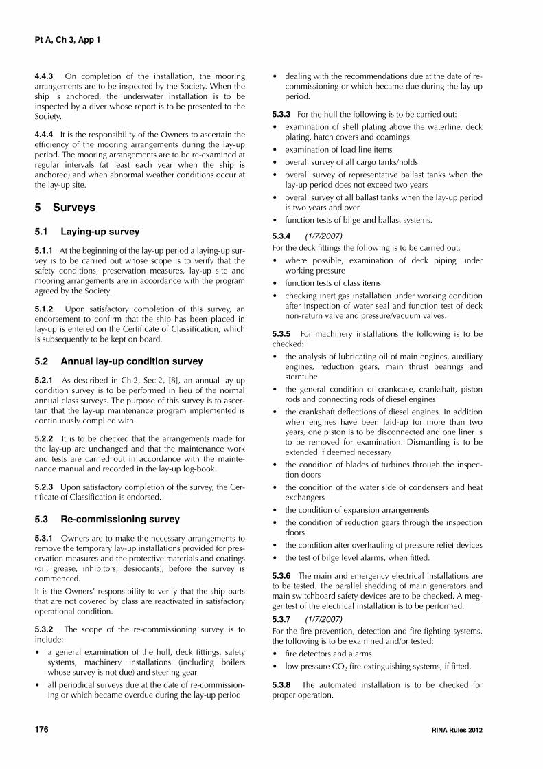
Pt A, Ch 3, App 1
176 RINA Rules 2012
4.4.3 On completion of the installation, the mooringarrangements are to be inspected by the Society. When theship is anchored, the underwater installation is to beinspected by a diver whose report is to be presented to theSociety.
4.4.4 It is the responsibility of the Owners to ascertain theefficiency of the mooring arrangements during the lay-upperiod. The mooring arrangements are to be re-examined atregular intervals (at least each year when the ship isanchored) and when abnormal weather conditions occur atthe lay-up site.
5 Surveys
5.1 Laying-up survey
5.1.1 At the beginning of the lay-up period a laying-up sur-vey is to be carried out whose scope is to verify that thesafety conditions, preservation measures, lay-up site andmooring arrangements are in accordance with the programagreed by the Society.
5.1.2 Upon satisfactory completion of this survey, anendorsement to confirm that the ship has been placed inlay-up is entered on the Certificate of Classification, whichis subsequently to be kept on board.
5.2 Annual lay-up condition survey
5.2.1 As described in Ch 2, Sec 2, [8], an annual lay-upcondition survey is to be performed in lieu of the normalannual class surveys. The purpose of this survey is to ascer-tain that the lay-up maintenance program implemented iscontinuously complied with.
5.2.2 It is to be checked that the arrangements made forthe lay-up are unchanged and that the maintenance workand tests are carried out in accordance with the mainte-nance manual and recorded in the lay-up log-book.
5.2.3 Upon satisfactory completion of the survey, the Cer-tificate of Classification is endorsed.
5.3 Re-commissioning survey
5.3.1 Owners are to make the necessary arrangements toremove the temporary lay-up installations provided for pres-ervation measures and the protective materials and coatings(oil, grease, inhibitors, desiccants), before the survey iscommenced.
It is the Owners’ responsibility to verify that the ship partsthat are not covered by class are reactivated in satisfactoryoperational condition.
5.3.2 The scope of the re-commissioning survey is toinclude:
• a general examination of the hull, deck fittings, safetysystems, machinery installations (including boilerswhose survey is not due) and steering gear
• all periodical surveys due at the date of re-commission-ing or which became overdue during the lay-up period
• dealing with the recommendations due at the date of re-commissioning or which became due during the lay-upperiod.
5.3.3 For the hull the following is to be carried out:
• examination of shell plating above the waterline, deckplating, hatch covers and coamings
• examination of load line items
• overall survey of all cargo tanks/holds
• overall survey of representative ballast tanks when thelay-up period does not exceed two years
• overall survey of all ballast tanks when the lay-up periodis two years and over
• function tests of bilge and ballast systems.
5.3.4 (1/7/2007)For the deck fittings the following is to be carried out:
• where possible, examination of deck piping underworking pressure
• function tests of class items
• checking inert gas installation under working conditionafter inspection of water seal and function test of decknon-return valve and pressure/vacuum valves.
5.3.5 For machinery installations the following is to bechecked:
• the analysis of lubricating oil of main engines, auxiliaryengines, reduction gears, main thrust bearings andsterntube
• the general condition of crankcase, crankshaft, pistonrods and connecting rods of diesel engines
• the crankshaft deflections of diesel engines. In additionwhen engines have been laid-up for more than twoyears, one piston is to be disconnected and one liner isto be removed for examination. Dismantling is to beextended if deemed necessary
• the condition of blades of turbines through the inspec-tion doors
• the condition of the water side of condensers and heatexchangers
• the condition of expansion arrangements
• the condition of reduction gears through the inspectiondoors
• the condition after overhauling of pressure relief devices
• the test of bilge level alarms, when fitted.
5.3.6 The main and emergency electrical installations areto be tested. The parallel shedding of main generators andmain switchboard safety devices are to be checked. A meg-ger test of the electrical installation is to be performed.
5.3.7 (1/7/2007)For the fire prevention, detection and fire-fighting systems,the following is to be examined and/or tested:
• fire detectors and alarms
• low pressure CO2 fire-extinguishing systems, if fitted.
5.3.8 The automated installation is to be checked forproper operation.
Pt A, Ch 3, App 1
RINA Rules 2012 177
5.3.9 When classed, the installations for refrigerated cargoare to be examined under working conditions. Where thelay-up period exceeds two years, representative compo-nents of the installation are to be dismantled.
5.3.10 For cargo installations on liquefied gas carriers, thefollowing is to be carried out:• inspection of the primary barrier in tanks• for membrane tanks, a global gas test of tanks whose
results are to be compared with those obtained at ship’sdelivery
• testing of gas piping at working pressure using inert gas.
A Surveyor of the Society is to attend the first cooling downand loading of the ship.
5.3.11 For other specific classed installations, the Ownersare to submit a survey program to the Society.
5.3.12 On completion of the above surveys and tests, seatrials are to be performed in the presence of a Surveyor ofthe Society.
The sea trials are to include :
• verification of the satisfactory performance of the deckinstallations, main propulsion system and essential aux-iliaries, including a test of the safety devices
• an anchoring test
• complete tests of steering gear
• full head and full astern tests
• tests of automated machinery systems, where applicable
5.3.13 Upon satisfactory completion of the surveys, anendorsement to confirm the carrying out of all relevant sur-veys and the re-commissioning of the ship is entered on theCertificate of Classification.


RINA Rules 2012 179
Part AClassification and Surveys
Chapter 4
SCOPE OF SURVEYS IN RESPECT OF THEDIFFERENT SERVICES OF SHIPS
SECTION 1 GENERAL
SECTION 2 BULK CARRIERS AND COMBINATION CARRIERS OF SINGLE SIDE SKIN CONSTRUCTION
SECTION 3 OIL TANKERS AND COMBINATION CARRIERS
SECTION 4 DOUBLE HULL OIL TANKERS
SECTION 5 CHEMICAL TANKERS
SECTION 6 LIQUEFIED GAS CARRIERS
SECTION 7 RO-RO CARGO SHIPS, PASSENGER SHIPS, RO-RO PASSENGER SHIPS
SECTION 8 GENERAL DRY CARGO SHIPS
SECTION 9 DOUBLE SKIN BULK CARRIERS
SECTION 10 OTHER SERVICE NOTATIONS
APPENDIX 1 SURVEY REPORTING PRINCIPLES FOR SHIPS SUBJECT TO ENHANCED SURVEY PROGRAM


Pt A, Ch 4, Sec 1
RINA Rules 2012 181
SECTION 1 GENERAL
1 General
1.1
1.1.1 The purpose of this Chapter is to give details on thescope of surveys of certain ships which, due to the servicenotation assigned and related equipment, need specificrequirements to be verified for the maintenance of theirclass.
1.1.2 These specific requirements either are additional toor supersede those stipulated in Chapter 3, which gives gen-eral requirements for surveys applicable to all types ofships: this is indicated in each Section of this Chapter. Thesesurveys are to be carried out at intervals as described inCh 2, Sec 2, concurrently with the surveys of the same type,i.e. annual, intermediate or class renewal surveys, detailedin Chapter 3.
1.1.3 (1/7/2002)Where specific requirements are given in this Chapter forthe class renewal survey, they are additional to the applica-ble requirements for the annual survey.
2 Service notations subject to addi-tional surveys
2.1
2.1.1 The specific requirements detailed in this Chapterare linked to the service notation(s) assigned to the ship atthe request of the Owner. Where a ship has more than oneservice notation, the specific requirements linked to eachone are applicable, insofar as they are not contradictory (insuch case, the most stringent requirement will be applied).
2.1.2 Tab 1 indicates which service notations are subjectto specific requirements, and in which Section or Articlethey are specified.
Table 1 : Service notations for which specific requirements are applicable (1/7/2011)
Service notation assignedSection or Article applicable in
this ChapterType of surveys affected by these specific requirements
Remarks
asphalt tanker Sec 10, [15] annual surveyintermediate surveyclass renewal survey
Not subject to enhanced survey program
bulk carrier ESPore carrier ESPbulk carrier ESP CSR
Sec 2 or Sec 9 (as applicable) annual surveyintermediate surveyclass renewal survey
Subject to enhanced sur-vey program
asphalt tanker ESPoil tanker ESPcombination carrier/OBO ESPcombination carrier/OOC ESPoil tanker ESP CSR
Sec 3, Sec 4 or Sec 9 (as applicable)
annual surveyintermediate surveyclass renewal survey
Subject to enhanced sur-vey program
chemical tanker Sec 5 annual surveyintermediate surveyclass renewal survey
Not subject to enhanced survey program
chemical tanker ESP Sec 5 annual surveyintermediate surveyclass renewal survey
Subject to enhanced sur-vey program
oil tanker Sec 3 annual surveyintermediate surveyclass renewal survey
Not subject to enhanced survey program
liquefied gas carrier Sec 6 annual surveyintermediate surveyclass renewal survey
ro-ro cargo shippassenger shipro-ro passenger ship
Sec 7 annual surveyclass renewal survey
Survey of shell and inner doors is included

Pt A, Ch 4, Sec 1
182 RINA Rules 2012
general dry cargo ship Sec 8 annual surveyintermediate surveyclass renewal survey
container ship or ship equipped for car-riage of containers
Sec 10, [2] annual surveyclass renewal survey
livestock carrier Sec 10, [3] annual surveyclass renewal survey
FLS tanker Sec 10, [4] annual surveyintermediate surveyclass renewal survey
dredgerhopper dredgerhopper unitsplit hopper unitsplit hopper dredger
Sec 10, [5] annual surveyclass renewal survey
tugsalvage tugescort tug
Sec 10, [6] annual surveyclass renewal survey
supply vessel Sec 10, [7] annual surveyintermediate surveyclass renewal survey
fire-fighting ship Sec 10, [8] annual surveyclass renewal survey
oil recovery ship Sec 10, [9] annual surveyclass renewal survey
cable laying ship Sec 10, [10] annual surveyclass renewal survey
fishing vessel Sec 10, [11] annual surveyclass renewal survey
pipe laying ship Sec 10, [12] annual surveyclass renewal survey
research ship Sec 10, [13] annual surveyclass renewal survey
cement carrier Sec 10, [14] annual surveyclass renewal survey
Service notation assignedSection or Article applicable in
this ChapterType of surveys affected by these specific requirements
Remarks

Pt A, Ch 4, Sec 2
RINA Rules 2012 183
SECTION 2 BULK CARRIERS AND COMBINATION CARRIERS
OF SINGLE SIDE SKIN CONSTRUCTION
1 General
1.1 Application
1.1.1 (1/7/2006)
The requirements of this Section apply to all self-propelledbulk carriers other than double skin bulk carriers as definedin Sec 9. These ships are assigned with one of the followingservice notations:
• bulk carrier ESP
• bulk carrier ESP CSR
• combination carrier/OBO ESP (see Note 1)
• combination carrier/OOC ESP (see Note 1)
Note 1: For single skin combination carriers additional require-ments are specified in Sec 3.
1.1.2 (1/7/2006)
The requirements apply to the surveys of the hull structureand piping systems in way of cargo holds, cofferdams, pipetunnels, fuel oil tanks and void spaces within the cargolength area and all salt water ballast tanks. They are addi-tional to the requirements applicable to the remainder ofthe ship, given in Chapter 3 according to the relevant sur-veys.
1.1.3 The requirements contain the minimum extent ofexamination, thickness measurements and tank testing.When substantial corrosion, as defined in Ch 2, Sec 2,[2.2.7], and/or structural defects are found, the survey is tobe extended and is to include additional close-up surveyswhen necessary.
1.1.4 (1/7/2004)
Ships required to comply with the provisions in Ch 6, App 1are subject to the additional thickness measurement guid-ance in Ch 6, Sec 2, [1.3] for the vertically corrugated trans-verse watertight bulkhead between cargo holds Nos. 1 and2 for purposes of determining compliance with Ch 6, App 1prior to the relevant compliance deadline stipulated inCh 6, Sec 2, [1.2] and at subsequent intermediate surveys(for ships over 10 years of age) and special surveys for pur-poses of verifying continuing compliance with Ch 6, App 1.
1.1.5 (1/7/2004)
Ships required to comply with the provisions in Ch 6, Sec 2,[7] are subject to the additional thickness measurementguidance in Ch 6, App 2 for side shell frames and bracketsfor the purposes of determining compliance with Ch 6,Sec 2, [7] prior to the relevant compliance deadline stipu-lated in Ch 6, Sec 2, [7] and at subsequent intermediate and
special surveys for purposes of verifying continuing compli-ance with Ch 6, Sec 2, [7].
1.1.6 (1/1/2003)
When, in any survey, thickness measurements are required :
• the procedure detailed in Ch 2, Sec 2, [2.3] is to beapplied
• the thickness measurement company is to be part of thesurvey planning meeting held prior to commencing thesurvey.
1.1.7 (1/7/2006)
Special consideration may be given to the extent of close-up surveys and/or thickness measurements in cargo holds asrequired below for class renewal, intermediate or annualsurveys, when all internal and external surfaces of hatchcoamings and hatch covers, and all internal surfaces of thecargo holds, excluding the flat tank top areas and the hop-per tank sloped plating approximately 300 mm below theside shell frame end brackets, have protective coating ingood condition.
The above special consideration may also be given to exist-ing bulk carriers, where Owners elect to coat or re-coatcargo holds, in accordance with the Manufacturers’ recom-mendations. However, prior to re-coating the cargo holds,scantlings are to be assessed in the presence of a Surveyorof the Society.
1.1.8 (1/7/2006)
For bulk carriers with hybrid cargo hold arrangements, e.g.with some cargo holds of single side skin and others of dou-ble side skin, the requirements of Sec 9 are to apply tocargo holds of double side skin and associated wing spaces.
1.2 Documentation on board
1.2.1 The Owner is to supply and maintain documentationon board as specified in [1.2.2] and [1.2.3], which is to bereadily available for examination by the Surveyor.
The documentation is to be kept on board for the lifetime ofthe ship.
1.2.2 A survey report file is to be a part of the documenta-tion on board consisting of:
• reports of structural surveys
• hull condition evaluation report (summarising theresults of class renewal surveys)
• thickness measurement reports.
The survey report file is also to be available in the Owner'smanagement office.

Pt A, Ch 4, Sec 2
184 RINA Rules 2012
1.2.3 (1/1/2008)The following additional supporting documentation is to beavailable on board:
• survey program, as required in [4.1], until such time asthe class renewal survey or the intermediate survey, asapplicable, has been completed
• main structural plans of cargo holds and ballast tanks
• previous repair history
• cargo and ballast history
• ship’s personnel reports on:
- structural deterioration/defects in general
- leakage in bulkheads and piping systems
- condition of coatings or corrosion prevention sys-tems, if any
• any other information that may help to identify criticalstructural areas and/or suspect areas requiring inspec-tion.
1.2.4 Prior to survey, the Surveyor examines the documen-tation on board and its contents, which are used as a basisfor the survey.
1.3 Reporting and evaluation of surveys
1.3.1 The data and information on the structural conditionof the ship collected during survey are evaluated for accept-ability and structural integrity of the ship's cargo area.
1.3.2 (1/7/2006)For ships subject to the requirements of this Section, the sur-veys of hull structure and piping systems are reported inconformance to the Survey Reporting Principles laid downin App 1.
1.3.3 A hull condition evaluation report (summarising theresults of class renewal surveys) is issued by the Society tothe Owner, who is to place it on board the ship for refer-ence at future surveys. The hull condition evaluation reportis endorsed by the Society.
1.4 Access to structures1.4.1 (1/1/2007)For overall surveys, means are to be provided to enable theSurveyor to examine the hull structure in a safe and practi-cal way.
1.4.2 (1/1/2007)For close-up surveys of the hull structure, other than cargohold shell frames, one or more of the following means foraccess, acceptable to the Surveyor, are to be provided:
• permanent staging and passages through structures;
• temporary staging and passages through structures;
• lifts and movable platforms;
• boats or rafts;
• portable ladders;
• other equivalent means.
1.4.3 (1/7/2008)For close-up surveys of the cargo hold shell frames of bulkcarriers less than 100000 dwt, one or more of the following
means for access, acceptable to the Surveyor, are to be pro-vided:
• permanent staging and passages through structures;
• temporary staging and passages through structures;
• portable ladder restricted to not more than 5 m in lengthmay be accepted for surveys of lower section of a shellframe including bracket;
• hydraulic arm vehicles such as conventional cherrypickers, lifts and movable platforms;
• boats or rafts provided the structural capacity of thehold is sufficient to withstand static loads at all levels ofwater;
• other equivalent means.
1.4.4 (1/7/2008)
For close-up surveys of the cargo hold shell frames of bulkcarriers of 100000 dwt and above, the use of portable lad-ders is not accepted, and one or more of the followingmeans for access, acceptable to the Surveyor, are to be pro-vided:
a) Annual surveys, intermediate survey under 10 years ofage and class renewal survey no. 1:
• permanent staging and passages through structures;
• temporary staging and passages through structures;
• hydraulic arm vehicles such as conventional cherrypickers, lifts and movable platforms;
• boats or rafts provided the structural capacity of thehold is sufficient to withstand static loads at all lev-els of water;
• other equivalent means.
b) Subsequent intermediate surveys and class renewal sur-veys:
• either permanent or temporary staging and passagethrough structures for close-up survey of at least theupper part of hold frames;
• hydraulic arm vehicles such as conventional cherrypickers for surveys of lower and middle parts of shellframes as an alternative to staging;
• lifts and movable platforms;
• boats or rafts provided the structural capacity of thehold is sufficient to withstand static loads at all lev-els of water;
• other equivalent means.
Notwithstanding the above requirements, the use of a porta-ble ladder fitted with a mechanical device to secure theupper end of the ladder is acceptable for the "close-upexamination of sufficient extent, minimum 25% of frames,to establish the condition of the lower region of the shellframes including approx. lower one third length of sideframe at side shell and side frame end attachment and theadjacent shell plating" as required in the forward cargo holdat annual surveys of ships between 10 and 15 years of age(see [2.4.1] b)) and as required in the forward cargo holdand one other selected cargo hold at annual surveys ofships over 15 years of age (see [2.4.2] b)).

Pt A, Ch 4, Sec 2
RINA Rules 2012 185
2 Annual survey
2.1 General
2.1.1 (1/1/2008)
The survey is to consist of an examination for the purpose ofensuring, as far as practicable, that the hull, weather decks,hatch covers, coamings and piping are maintained in a sat-isfactory condition.
2.2 Hull and equipment
2.2.1 (1/7/2006)
Examination of:
• the hull plating and its closing appliances as far as canbe seen
• the watertight penetrations as far as practicable.
2.3 Weather decks, hatch covers and coam-ings
2.3.1 (1/7/2006)
Confirmation is to be obtained that no unapproved changeshave been made to the hatch covers, hatch coamings andtheir securing and sealing devices since the last survey.
2.3.2 (1/1/2008)
A thorough survey of cargo hatch covers and coamings isonly possible by examination in the open as well as closedpositions and is to include verification of proper openingand closing operation. As a result, the hatch cover setswithin the forward 25% of the ship's length and at least oneadditional set, such that all sets on the ship are assessed atleast once in every 5-year period, are to be surveyed open,closed and in operation to the full extent in each directionat each annual survey, including:
a) stowage and securing in open condition;
b) proper fit and efficiency of sealing in closed condition;and
c) operational testing of hydraulic and power components,wires, chains, and link drives.
The closing of the covers is to include the fastening of allperipheral and cross-joint cleats or other securing devices.Particular attention is to be paid to the condition of thehatch covers in the forward 25% of the ship's length, wheresea loads are normally greatest.
2.3.3 (1/1/2008)
If there are indications of difficulty in operating and secur-ing hatch covers, additional sets above those required by[2.3.2], at the discretion of the Surveyor, are to be tested inoperation.
2.3.4 (1/1/2008)
Where the cargo hatch securing system does not functionproperly, repairs are to be carried out under the supervisionof the Society.
2.3.5 (1/1/2008)For each cargo hatch cover set, at each annual survey, thefollowing items are to be surveyed:
a) cover panels, including side plates, and stiffener attach-ments that may be accessible in the open position byclose-up survey (for corrosion, cracks, and deforma-tion);
b) sealing arrangements of perimeter and cross-joints (gas-kets for condition and permanent deformation, flexibleseals on combination carriers, gasket lips, compressionbars, drainage channels and non-return valves);
c) clamping devices, retaining bars, cleating (for wastage,adjustment and condition of rubber components);
d) closed cover locating devices (for distortion and attach-ment);
e) chain or rope pulleys;
f) guides;
g) guide rails and track wheels;
h) stoppers;
i) wires, chains, tensioners, and gypsies;
j) hydraulic system, electrical safety devices and inter-locks;
k) end and interpanel hinges, pins and stools where fitted.
2.3.6 (1/1/2008)At each hatchway, at each annual survey, the coamings,with panel stiffeners and brackets are to be checked for cor-rosion, cracks and deformation, especially of the coamingtops, including close-up survey.
2.3.7 (1/1/2008)Where considered necessary, the effectiveness of sealingarrangements may be proved by hose or chalk testing sup-plemented by dimensional measurements of seal compress-ing components.
2.3.8 (1/1/2008)Where portable covers or wooden or steel pontoons are fit-ted, they are to be examined to confirm the satisfactory con-dition, where applicable, of:
a) wooden covers and portable beams, carriers or socketsfor the portable beams, and their securing devices;
b) steel pontoons, including close-up survey of hatch coverplating;
c) tarpaulins;
d) cleats, battens and wedges;
e) hatch securing bars and their securing devices;
f) loading pads/bars and the side plate edge;
g) guide plates and chocks;
h) compression bars, drainage channels and drain pipes (ifany).
2.3.9 (1/7/2006)Examination of flame screens on vents to all bunker tanks.
2.3.10 (1/7/2006)Examination of bunker and vent piping systems, includingventilators.

Pt A, Ch 4, Sec 2
186 RINA Rules 2012
2.4 Cargo holds
2.4.1 Ships between 10 and 15 years of age (1/1/2008)
The requirements of the survey, which are also given in Tab1 and Tab 2, are the following.
a) Overall survey of all cargo holds.
b) Close-up survey of sufficient extent, minimum 25% offrames, to establish the condition of the lower region ofthe shell frames including approx. lower one thirdlength of side frame at side shell and side frame endattachment and the adjacent shell plating in the forwardcargo hold. Where this level of survey reveals the needfor remedial measures, the survey is to be extended toinclude a close-up survey of all of the shell frames andadjacent shell plating of that cargo hold as well as aclose-up survey of sufficient extent of all remainingcargo holds.
c) When considered necessary by the Surveyor, or whereextensive corrosion exists, thickness measurement is tobe carried out. If the results of these thickness measure-ments indicate that substantial corrosion is found, theextent of thickness measurements is to be increased inaccordance with Tab 7 to Tab 11. These extended thick-ness measurements are to be carried out before theannual survey is credited as completed. Suspect areasidentified at previous surveys are to be examined. Areasof substantial corrosion identified at previous surveysare to be subjected to thickness measurements.
d) Where a hard protective coating is fitted in cargo holdsas provided in [1.1.7] and is found to be in good condi-tion, the extent of close-up surveys and thickness meas-urements may be specially considered.
e) All piping and penetrations in cargo holds, includingoverboard piping, are to be examined.
2.4.2 Ships over 15 years of age (1/1/2008)The requirements of the survey, which are also given in Tab1 and Tab 2, are the following.
a) Overall survey of all cargo holds.
b) Close-up survey of sufficient extent, minimum 25% offrames, to establish the condition of the lower region ofthe shell frames including approx. lower one thirdlength of side frame at side shell and side frame endattachment and the adjacent shell plating in the forwardcargo hold and one other selected cargo hold. Wherethis level of survey reveals the need for remedial meas-ures, the survey is to be extended to include a close-upsurvey of all of the shell frames and adjacent shell plat-ing of that cargo hold as well as a close-up survey ofsufficient extent of all remaining cargo holds.
c) When considered necessary by the Surveyor, or whereextensive corrosion exists, thickness measurement is tobe carried out. If the results of these thickness measure-ments indicate that substantial corrosion is found, theextent of thickness measurements is to be increased inaccordance with Tab 7 to Tab 11. These thickness meas-urements are to be carried out before the annual surveyis credited as completed. Suspect areas identified at pre-vious surveys are to be examined. Areas of substantial
corrosion identified at previous surveys are to be sub-jected to thickness measurements.
d) Where a hard protective coating is fitted in cargo holdsas provided in [1.1.7] and is found to be in good condi-tion, the extent of close-up surveys and thickness meas-urements may be specially considered.
e) All piping and penetrations in cargo holds, includingoverboard piping, are to be examined.
2.4.3 Ships subject to SOLAS regulation XII/9.1 (1/7/2006)
This item contains additional requirements for the foremostcargo hold of ships subject to Reg. 9.1 of Ch. XII of SOLAS74 as amended, which are those meeting all the followingconditions:
• bulk carriers of 150 m in length and upwards of singleside skin construction,
• carrying solid bulk cargoes having a density of 1,780t/m3 and above,
• contracted for construction (see Note 1) before 1 July1999, and
• constructed with an insufficient number of transversewatertight bulkheads to enable them to withstand flood-ing of the foremost cargo hold in all loading conditionsand remain afloat in a satisfactory condition of equilib-rium as specified in Reg. 4.3 of Ch. XII of SOLAS 74 asamended.
In accordance with Reg. 9.1 of Ch. XII of SOLAS 74 asamended, for the foremost cargo hold of the above ships,the additional survey requirements given in Tab 2 are to beincluded in the scope of the annual survey.Note 1: "The "contracted for construction" date means the date onwhich the contract to build the vessel is signed between the pro-spective owner and the shipbuilder. For further details regarding thedate of "contract for construction", refer to IACS ProceduralRequirement (PR) No.29."
2.5 Ballast tanks
2.5.1 Ballast tanks are to be internally examined whenrequired as a consequence of the results of the classrenewal survey and intermediate survey.
2.5.2 (1/1/2004)When considered necessary by the Surveyor, or whereextensive corrosion exists, thickness measurements are is tobe carried out. If the results of these thickness measure-ments indicate that substantial corrosion is found, the extentof thickness measurements is to be increased in accordancewith Tab 7 to Tab 11. These extended thickness measure-ments are to be carried out before the survey is credited ascompleted.
2.5.3 (1/7/2001)Suspect areas identified at previous surveys are to be exam-ined. Areas of substantial corrosion identified at previoussurveys are to be subjected to thickness measurements.
2.5.4 (1/7/2011)Confirmation is to be given that the corrosion preventionsystem fitted to dedicated ballast water tanks when appro-priate is maintained.

Pt A, Ch 4, Sec 2
RINA Rules 2012 187
2.6 Additional requirements after determin-ing compliance with SOLAS regulation XII/12 (water level detectors) and XII/13 (availability of pumping systems)
2.6.1 (1/1/2007)
For ships complying with the requirements of SOLAS XII/12for hold, ballast and dry space water level detectors, theannual survey is to include an examination and a test, atrandom, of the water ingress detection systems and of theiralarms.
2.6.2 (1/1/2007)
For ships complying with the requirements of SOLAS XII/13for the availability of pumping systems, the annual survey isto include an examination and a test of the means for drain-ing and pumping ballast tanks forward of the collision bulk-head and bilges of dry spaces, any part of which extendsforward of the foremost cargo hold, and of their controls.
2.7 Means of access
2.7.1 (1/7/2011)
Confirmation is to be given, when appropriate and as far asis practicable when internal spaces are examined, that themeans of access to cargo and other spaces remain in goodcondition.
3 Intermediate survey - Hull items
3.1 General
3.1.1 (1/7/2006)
The survey extent is dependent on the age of the ship asspecified in [3.2], [3.3] and [3.4] and shown in Tab 3 andTab 4.
3.2 Ships between 5 and 10 years of age
3.2.1 Ballast tanks (1/7/2010)
a) For tanks used for water ballast, an overall survey of rep-resentative tanks selected by the Surveyor is to be car-ried out. The selection is to include fore and aft peaktanks and a number of other tanks, taking into accountthe total number and type of ballast tanks. If such over-all survey reveals no visible structural defects, the exam-ination may be limited to verification that the corrosionprevention system remains efficient.
b) Where poor coating condition, corrosion or otherdefects are found in water ballast tanks or where a hardprotective coating has not been applied since the timeof construction, the examination is to be extended toother ballast tanks of the same type.
c) In ballast tanks other than double bottom tanks, where ahard protective coating is found in poor condition, andit is not renewed, or where a soft or semi-hard coatinghas been applied, or where a hard protective coating
has not been applied since the time of construction, thetanks in question are to be examined and thicknessmeasurements carried out as considered necessary atannual surveys. When such breakdown of hard protec-tive coating is found in ballast double bottom tanks, orwhere a soft or semi-hard coating has been applied, orwhere a hard protective coating has not been applied,the tanks in question may be examined at annual sur-veys. When considered necessary by the Surveyor, orwhere extensive corrosion exists, thickness measure-ments are to be carried out.
d) In addition to the requirements above, suspect areasidentified at previous surveys are to be examined.
3.2.2 Cargo holds (1/7/2006)
a) An overall survey of all cargo holds, including close-upsurvey of sufficient extent, minimum 25% of frames, isto be carried out to establish the condition of:
• Shell frames including their upper and lower endattachments, adjacent shell plating, and transversebulkheads in the forward cargo hold and one otherselected cargo hold;
• Areas found suspect at previous surveys.
b) Where considered necessary by the Surveyor as a resultof the overall and close-up survey as described in a), thesurvey is to be extended to include a close-up survey ofall of the shell frames and adjacent shell plating of thatcargo hold as well as a close-up survey of sufficientextent of all remaining cargo holds.
3.2.3 Extent of Thickness Measurements (1/7/2006)
a) Thickness measurements are to be carried out to anextent sufficient to determine both general and localcorrosion levels in areas subject to close-up survey asdescribed in [3.2.2] a). The minimum requirements forthickness measurements at the intermediate survey areareas found to be suspect areas at previous surveys.
b) The extent of thickness measurement may be speciallyconsidered, provided the Surveyor is satisfied by theclose-up survey that there is no structural diminutionand the hard protective coatings are found to be in agood condition.
c) Where substantial corrosion is found, the extent ofthickness measurements is to be increased in accord-ance with the requirements of Tab 7 to Tab 11. Theseextended thickness measurements are to be carried outbefore the survey is credited as completed. Suspectareas identified at previous surveys are to be examined.Areas of substantial corrosion identified at previous sur-veys are to be subjected to thickness measurements.
d) Where the hard protective coating in cargo holds, asdefined in [1.1.7], is found in good condition, the extentof close-up surveys and thickness measurements may bespecially considered.

Pt A, Ch 4, Sec 2
188 RINA Rules 2012
Table 1 : Annual survey of cargo holds for bulk carriers and combination carriers of single side skin construction (1/7/2006)
Table 2 : Additional survey requirements for the foremost cargo hold for ships subject to Reg. 9.1 of Ch. XII of SOLAS 74 as amended, only for ships referred to in [2.4.3] (1/7/2006)
Age of ship (in years at time of annual survey)
10 < age ≤ 15 age > 15
Overall survey of all cargo holds Overall survey of all cargo holds
Close-up survey of sufficient extent, minimum 25% of frames, to establish the condition of the lower region of the shell frames including approximately the lower one third length of side frame at side shell and side frame end attachment and the adjacent shell plating in the forward cargo hold
Close-up survey of sufficient extent, minimum 25% of frames, to establish the condition of the lower region of the shell frames including approximately the lower one third length of side frame at side shell and side frame end attachment and the adjacent shell plating in the forward cargo hold and one other selected cargo hold
Examination of all piping and penetrations, including overboard piping, in all cargo holds
See (1) , (2) and (3) See (1) , (2) and (3)
(1) Where this level of survey reveals the need for remedial measures, the survey is to be extended to include a close-up survey of all the shell frames and adjacent shell plating of that cargo hold as well as a close-up survey of sufficient extent of all remaining cargo holds.
(2) When considered necessary by the Surveyor or where extensive corrosion exists, thickness measurements are to be carried out. If the results of these thickness measurements indicate that substantial corrosion is present, the extent of thickness measurements is to be increased in accordance with Tab 7 to Tab 11. These extended thickness measurements are to be carried out before the survey is credited as completed. Suspect areas identified at previous surveys are to be examined. Areas of substantial corrosion identified at previous surveys are to be subjected to thickness measurements.
(3) Where a hard protective coating is fitted in cargo holds as provided in [1.1.7] and is found to be in good condition, the extent of close-up surveys and thickness measurements may be specially considered.
Age of ship (in years at time of annual survey)
5 < age ≤ 15 age > 15
Overall survey of the foremost cargo hold, including close-up sur-vey of sufficient extent to establish the condition of:• minimum 25% of shell frames including their upper and lower
end attachments, adjacent shell plating, and transverse bulk-heads
• suspect areas identified at previous surveys (see Ch 2, Sec 2, [2.2.8])
See (1) and (2)
Overall survey of the foremost cargo hold, including close-up sur-vey of sufficient extent to establish the condition of:• all shell frames including their upper and lower end attach-
ments, adjacent shell plating, and transverse bulkheads• suspect areas identified at previous surveys (see Ch 2, Sec 2,
[2.2.8])See (2)
Thickness measurement to an extent sufficient to determine both general and local corrosion levels at areas subject to close-up sur-vey.See (3), (4) and (5)
Thickness measurement to an extent sufficient to determine both general and local corrosion levels at areas subject to close-up sur-vey.See (3), (4) and (5)
(1) Where considered necessary by the Surveyor as a result of the overall and close-up survey as described above, the survey is to be extended to include a close-up survey of all of the shell frames and adjacent shell plating of the foremost cargo hold.
(2) Where the protective coating in the foremost cargo hold as provided in [1.1.7] is found to be in good condition, the extent of close-up surveys and thickness measurements may be specially considered.
(3) The minimum requirements for thickness measurements are suspect areas identified at previous surveys (see Ch 2, Sec 2, [2.2.8]).
(4) Where substantial corrosion as defined in Ch 2, Sec 2, [2.2.7] is found, the extent of thickness measurements is to be increased in accordance with Tab 7 to Tab 11.These extended thickness measurements are to be carried out before the survey is credited as completed. Suspect Areas identi-fied at previous surveys are to be examined. Areas of substantial corrosion identified at previous surveys are to be subjected to thickness measurements.
(5) The thickness measurements may be dispensed with provided the Surveyor is satisfied by the close-up survey, that there is no structural diminution and the protective coating where fitted remains effective

Pt A, Ch 4, Sec 2
RINA Rules 2012 189
Table 3 : Intermediate survey of cargo holds for bulk carriers and combination carriers of single side skin construction (1/7/2006)
3.3 Ships between 10 and 15 years of age 3.3.1 (1/7/2006)The requirements of the intermediate survey are to the sameextent as the previous class renewal survey as required in[4]. However, internal examination of fuel oil tanks andpressure testing of all tanks are not required unless deemednecessary by the attending Surveyor.
3.3.2 (1/1/2003)In application of [3.3.1], the intermediate survey may becommenced at the second annual survey and be progressedduring the succeeding year with a view to completion at thethird annual survey in lieu of application of Ch 2, Sec 2,[4.2.2].
3.3.3 (1/1/2003)In application of [3.3.1], an underwater survey may be con-sidered in lieu of a bottom survey in dry condition (seeCh 3, Sec 5, [2]).
3.4 Ships over 15 years of age 3.4.1 (1/7/2006)The requirements of the intermediate survey are to the sameextent as the previous class renewal survey as required in[4]. However, internal examination of fuel oil tanks andpressure testing of all tanks are not required unless deemednecessary by the attending Surveyor.
3.4.2 (1/1/2003)In application of [3.4.1], the intermediate survey may becommenced at the second annual survey and be progressed
during the succeeding year with a view to completion at thethird annual survey in lieu of application of Ch 2, Sec 2,[4.2.2].
3.4.3 (1/7/2002)In application of [3.4.1], a bottom survey in dry condition isto be part of the intermediate survey. The overall and close-up surveys and thickness measurements, as applicable, ofthe lower portions of the cargo holds and ballast tanks (seeNote 1) are to be carried out in accordance with the appli-cable requirements for intermediate surveys, if not alreadyperformed.
Note 1: Lower portions of the cargo holds and ballast tanks areconsidered to be the parts below the light ballast waterline.
4 Class renewal survey
4.1 Survey program and preparation for sur-vey
4.1.1 (1/1/2008)The Owner, in cooperation with the Society, is to work out aspecific survey program prior to the commencement of anypart of:
• the class renewal survey
• the intermediate survey for bulk carriers over 10 years ofage.
Prior to the development of the survey program, the SurveyPlanning Questionnaire is to be completed by the Owner
Age of ship (in years at time of intermediate survey)5 < age ≤ 10 10 < age ≤ 15 age > 15
Overall survey of all cargo holds See [3.3] See [3.4]Close-up survey in the forward cargo hold and one other selected cargo hold, to establish the condition of:• at least 25% of the side shell frames including their upper and lower end
attachments, and adjacent shell plating• the transverse bulkheads• areas found suspect at previous surveys (see Ch 2, Sec 2, [2.2.8])
See [3.3] See [3.4]
See (1) and (2)Thickness measurements to an extent sufficient to determine both general and local corrosion levels in areas subject to close-up survey. The minimum requirement for thickness measurements are areas found to be suspect areas at previous surveys (see Ch 2, Sec 2, [2.2.8]).See (2), (3) and (4)
See [3.3] See [3.4]
(1) Where considered necessary by the Surveyor as a result of the overall and close-up surveys, the survey is to be extended to include a close-up survey of all the shell frames and adjacent shell plating of that cargo hold as well as a close-up survey of suf-ficient extent of all remaining cargo holds.
(2) Where the hard protective coating in cargo holds as defined in [1.1.7] is found in good condition, the extent of close-up sur-vey and thickness measurements may be specially considered.
(3) Where substantial corrosion is found, the extent of thickness measurements is to be increased in accordance with Tab 7 to Tab 11.These extended thickness measurements are to be carried out before the survey is credited as completed. Suspect areas identi-fied at previous surveys are to be examined. Areas of substantial corrosion identified at previous surveys are to be subjected to thickness measurements.
(4) The extent of thickness measurement may be specially considered provided the Surveyor is satisfied by the close-up survey, that there is no structural diminution and the hard protective coating is found to be in good condition.

Pt A, Ch 4, Sec 2
190 RINA Rules 2012
based on the information set out in [4.9], and forwarded tothe Society.
The survey program is to be in a written format, based onthe information in [4.8]. The survey is not to commenceuntil the survey program has been agreed. The survey pro-gram at intermediate survey may consist of the survey pro-gram at the previous class renewal survey supplemented bythe condition evaluation report of that class renewal surveyand later relevant survey reports.
The survey program is to be worked out taking into accountany amendments to the survey requirements after the lastclass renewal survey carried out.
4.1.2 (1/7/2006)In developing the survey program, the following documen-tation is to be collected and consulted with a view to select-ing tanks, holds, areas and structural elements to beexamined:
• survey status and basic ship information
• the documentation on board, as described in [1.2.2]and [1.2.3]
• main structural plans (scantling drawings), includinginformation on use of high tensile steels (HTS)
• relevant previous survey and inspection reports fromboth the Society and the Owner
• information on the use of ship holds and tanks, withregard to the nature of the typical cargoes transportedand other useful data
• information on the corrosion prevention level on thenew building
• information on the relevant maintenance level duringoperation.
4.1.3 The survey program is to comply, at least, with therequirements for close-up surveys, thickness measurementsand tank testing given in [4.4], [4.5] and [4.6], respectively.In addition, the survey program is to include at least:
• basic ship information and particulars
• main structural plans (scantling drawings), includinginformation on the use of high tensile steels (HTS)
• plan of holds and tanks
• list of holds and tanks including information on theiruse, protective coating, if any, and its condition
• conditions for survey, with regard to holds, tanks andspaces which are to be safe for access, i.e. cleaned, gasfreed, ventilated, illuminated
• provisions and methods for access to structures
• equipment for surveys
• nomination of holds, spaces and areas for close-up sur-veys according to Tab 5
• nomination of sections and areas for thickness measure-ments according to Tab 6
• nomination of holds, if any, and tanks for tank testingaccording to [4.6]
• damage experience and repair history related to the shipin question.
4.1.4 The survey program is also to include the maximumacceptable structural corrosion diminution levels applicableto the ship. The Society will advise the Owner of this infor-mation.
4.1.5 In addition, the survey program is to include propos-als on how to conduct surveys and tests in a safe and practi-cal way, including the means of providing access tostructures for close-up survey, thickness measurements andtank testing. All other provisions described in Ch 2, Sec 2,[2.3], Ch 2, Sec 2, [2.5], Ch 2, Sec 2, [2.6], Ch 2, Sec 2,[2.7] and Ch 2, Sec 2, [2.8] regarding procedures for thick-ness measurements, conditions for survey, access to struc-tures, equipment for survey and survey at sea or atanchorage, respectively, are also to be complied with.
4.1.6 Survey Planning Meeting (1/7/2010)
The establishment of proper preparation and close co-oper-ation between the attending Surveyor(s) and the Owner'srepresentatives on board prior to and during the survey arean essential part in the safe and efficient conduct of the sur-vey. During the survey on board safety meetings are to beheld regularly.
Prior to commencement of any part of the renewal andintermediate survey, a survey planning meeting is to be heldbetween the attending Surveyor(s), the Owner's representa-tive in attendance, the thickness measurement companyrepresentative, where involved, and the Master of the shipor an appropriately qualified representative appointed bythe Master or Company for the purpose of ascertaining thatall the arrangements envisaged in the survey program are inplace, so as to ensure the safe and efficient conduct of thesurvey work to be carried out. Refer also to Ch 2, Sec 2,[2.3.1].
The following is an indicative list of items that are to beaddressed in the meeting:
a) schedule of the ship (i.e. the voyage, docking andundocking manoeuvres, periods alongside, cargo andballast operations etc);
b) provisions and arrangements for thickness measure-ments (i.e. access, cleaning/de-scaling, illumination,ventilation, personal safety);
c) extent of the thickness measurements;
d) acceptance criteria (refer to the list of minimum thick-nesses);
e) extent of close-up survey and thickness measurementconsidering the coating condition and suspectareas/areas of substantial corrosion;
f) execution of thickness measurements;
g) taking representative readings in general and whereuneven corrosion/pitting is found;
h) mapping of areas of substantial corrosion;
i) communication between the attending Surveyor(s), thethickness measurement company operator(s) and theOwner's representative(s) concerning findings.
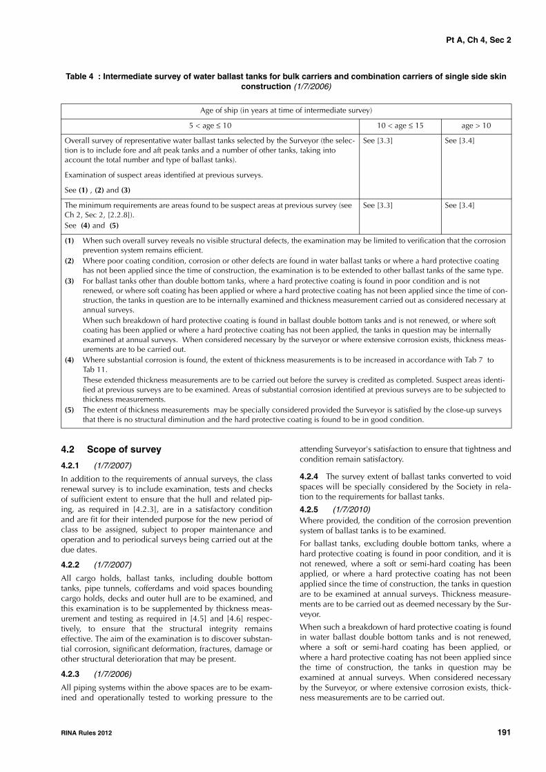
Pt A, Ch 4, Sec 2
RINA Rules 2012 191
Table 4 : Intermediate survey of water ballast tanks for bulk carriers and combination carriers of single side skin construction (1/7/2006)
4.2 Scope of survey
4.2.1 (1/7/2007)
In addition to the requirements of annual surveys, the classrenewal survey is to include examination, tests and checksof sufficient extent to ensure that the hull and related pip-ing, as required in [4.2.3], are in a satisfactory conditionand are fit for their intended purpose for the new period ofclass to be assigned, subject to proper maintenance andoperation and to periodical surveys being carried out at thedue dates.
4.2.2 (1/7/2007)
All cargo holds, ballast tanks, including double bottomtanks, pipe tunnels, cofferdams and void spaces boundingcargo holds, decks and outer hull are to be examined, andthis examination is to be supplemented by thickness meas-urement and testing as required in [4.5] and [4.6] respec-tively, to ensure that the structural integrity remainseffective. The aim of the examination is to discover substan-tial corrosion, significant deformation, fractures, damage orother structural deterioration that may be present.
4.2.3 (1/7/2006)
All piping systems within the above spaces are to be exam-ined and operationally tested to working pressure to the
attending Surveyor's satisfaction to ensure that tightness andcondition remain satisfactory.
4.2.4 The survey extent of ballast tanks converted to voidspaces will be specially considered by the Society in rela-tion to the requirements for ballast tanks.
4.2.5 (1/7/2010)Where provided, the condition of the corrosion preventionsystem of ballast tanks is to be examined.
For ballast tanks, excluding double bottom tanks, where ahard protective coating is found in poor condition, and it isnot renewed, where a soft or semi-hard coating has beenapplied, or where a hard protective coating has not beenapplied since the time of construction, the tanks in questionare to be examined at annual surveys. Thickness measure-ments are to be carried out as deemed necessary by the Sur-veyor.
When such a breakdown of hard protective coating is foundin water ballast double bottom tanks and is not renewed,where a soft or semi-hard coating has been applied, orwhere a hard protective coating has not been applied sincethe time of construction, the tanks in question may beexamined at annual surveys. When considered necessaryby the Surveyor, or where extensive corrosion exists, thick-ness measurements are to be carried out.
Age of ship (in years at time of intermediate survey)
5 < age ≤ 10 10 < age ≤ 15 age > 10
Overall survey of representative water ballast tanks selected by the Surveyor (the selec-tion is to include fore and aft peak tanks and a number of other tanks, taking into account the total number and type of ballast tanks).
See [3.3] See [3.4]
Examination of suspect areas identified at previous surveys.
See (1) , (2) and (3)
The minimum requirements are areas found to be suspect areas at previous survey (see Ch 2, Sec 2, [2.2.8]). See (4) and (5)
See [3.3] See [3.4]
(1) When such overall survey reveals no visible structural defects, the examination may be limited to verification that the corrosion prevention system remains efficient.
(2) Where poor coating condition, corrosion or other defects are found in water ballast tanks or where a hard protective coating has not been applied since the time of construction, the examination is to be extended to other ballast tanks of the same type.
(3) For ballast tanks other than double bottom tanks, where a hard protective coating is found in poor condition and is not renewed, or where soft coating has been applied or where a hard protective coating has not been applied since the time of con-struction, the tanks in question are to be internally examined and thickness measurement carried out as considered necessary at annual surveys.When such breakdown of hard protective coating is found in ballast double bottom tanks and is not renewed, or where soft coating has been applied or where a hard protective coating has not been applied, the tanks in question may be internally examined at annual surveys. When considered necessary by the surveyor or where extensive corrosion exists, thickness meas-urements are to be carried out.
(4) Where substantial corrosion is found, the extent of thickness measurements is to be increased in accordance with Tab 7 to Tab 11.These extended thickness measurements are to be carried out before the survey is credited as completed. Suspect areas identi-fied at previous surveys are to be examined. Areas of substantial corrosion identified at previous surveys are to be subjected to thickness measurements.
(5) The extent of thickness measurements may be specially considered provided the Surveyor is satisfied by the close-up surveys that there is no structural diminution and the hard protective coating is found to be in good condition.
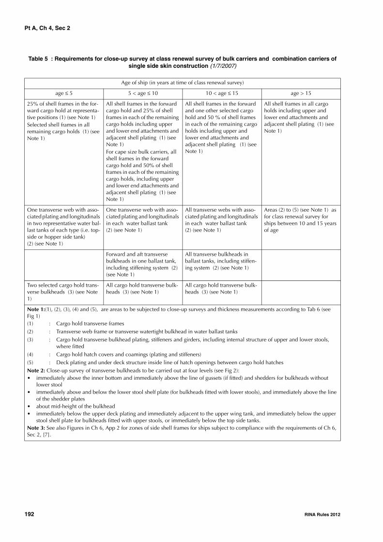
Pt A, Ch 4, Sec 2
192 RINA Rules 2012
Table 5 : Requirements for close-up survey at class renewal survey of bulk carriers and combination carriers of single side skin construction (1/7/2007)
Age of ship (in years at time of class renewal survey)
age ≤ 5 5 < age ≤ 10 10 < age ≤ 15 age > 15
25% of shell frames in the for-ward cargo hold at representa-tive positions (1) (see Note 1)Selected shell frames in all remaining cargo holds (1) (see Note 1)
All shell frames in the forward cargo hold and 25% of shell frames in each of the remaining cargo holds including upper and lower end attachments and adjacent shell plating (1) (see Note 1)For cape size bulk carriers, all shell frames in the forward cargo hold and 50% of shell frames in each of the remaining cargo holds, including upper and lower end attachments and adjacent shell plating (1) (see Note 1)
All shell frames in the forward and one other selected cargo hold and 50 % of shell frames in each of the remaining cargo holds including upper and lower end attachments and adjacent shell plating (1) (see Note 1)
All shell frames in all cargo holds including upper and lower end attachments and adjacent shell plating (1) (see Note 1)
One transverse web with asso-ciated plating and longitudinals in two representative water bal-last tanks of each type (i.e. top-side or hopper side tank) (2) (see Note 1)
One transverse web with asso-ciated plating and longitudinals in each water ballast tank (2) (see Note 1)
All transverse webs with asso-ciated plating and longitudinals in each water ballast tank (2) (see Note 1)
Areas (2) to (5) (see Note 1) as for class renewal survey for ships between 10 and 15 years of age
Forward and aft transverse bulkheads in one ballast tank, including stiffening system (2) (see Note 1)
All transverse bulkheads in ballast tanks, including stiffen-ing system (2) (see Note 1)
Two selected cargo hold trans-verse bulkheads (3) (see Note 1)
All cargo hold transverse bulk-heads (3) (see Note 1)
All cargo hold transverse bulk-heads (3) (see Note 1)
Note 1:(1), (2), (3), (4) and (5), are areas to be subjected to close-up surveys and thickness measurements according to Tab 6 (see Fig 1)(1) : Cargo hold transverse frames(2) : Transverse web frame or transverse watertight bulkhead in water ballast tanks(3) : Cargo hold transverse bulkhead plating, stiffeners and girders, including internal structure of upper and lower stools,
where fitted(4) : Cargo hold hatch covers and coamings (plating and stiffeners)(5) : Deck plating and under deck structure inside line of hatch openings between cargo hold hatchesNote 2: Close-up survey of transverse bulkheads to be carried out at four levels (see Fig 2):• immediately above the inner bottom and immediately above the line of gussets (if fitted) and shedders for bulkheads without
lower stool• immediately above and below the lower stool shelf plate (for bulkheads fitted with lower stools), and immediately above the line
of the shedder plates• about mid-height of the bulkhead• immediately below the upper deck plating and immediately adjacent to the upper wing tank, and immediately below the upper
stool shelf plate for bulkheads fitted with upper stools, or immediately below the top side tanks.Note 3: See also Figures in Ch 6, App 2 for zones of side shell frames for ships subject to compliance with the requirements of Ch 6, Sec 2, [7].

Pt A, Ch 4, Sec 2
RINA Rules 2012 193
4.2.6 (1/7/2006)
Where a hard protective coating is provided in cargo holds,as provided in [1.1.7], and is found to be in good condition,the extent of close-up surveys and thickness measurementsmay be specially considered.
4.2.7 (1/1/2003)
The proper operation of the water detection system in cargoholds is to be verified (only for ships subject to Reg. XII/9.1of SOLAS 1974 as amended).
4.2.8 (1/7/2006)
The class renewal survey is to include a bottom survey indry condition as laid down in Ch 3, Sec 6, [2.2.1].
The overall and close-up surveys and thickness measure-ments, as applicable, of the lower portions of the cargoholds and ballast tanks (see Note 1) are to be carried out inaccordance with the applicable requirements for classrenewal surveys, if not already performed.
Note 1: Lower portions of the cargo holds and ballast tanks areconsidered to be the parts below the light ballast waterline.
4.3 Hatch covers and coamings
4.3.1 (1/1/2008)
A thorough inspection of the items listed in [2.3] is to becarried out, in addition to all hatch covers and coamings.
4.3.2 (1/1/2008)A check of the satisfactory operation of all mechanicallyoperated hatch covers is to be made, including:
a) stowage and securing in open condition;
b) proper fit and efficiency of sealing in closed condition;
c) operational testing of hydraulic and power components,wires, chains and link drives.
4.3.3 (1/1/2008)A check of the effectiveness of sealing arrangements of allhatch covers by hose testing or equivalent is to be made.
4.3.4 (1/1/2008)Thickness measurement of the hatch cover and coamingplating and stiffeners is to be carried out as given in Tab 6.
4.4 Overall and close-up surveys4.4.1 (1/7/2006)An overall survey of all cargo holds, tanks and spaces is tobe carried out at each class renewal survey. For fuel oiltanks in the cargo length area, the requirements given inCh 3, Sec 5, Tab 5 are to be complied with.
4.4.2 (1/7/2006)The minimum requirements for close-up surveys at classrenewal survey are given in Tab 5.
4.4.3 (1/7/2006)The Surveyor may extend the close-up survey as deemednecessary taking into account the maintenance of thespaces under survey, the condition of the corrosion preven-tion system and where spaces have structural arrangements
All cargo hold hatch covers and coamings (4) (see Note 1)
All cargo hold hatch covers and coamings (4) (see Note 1)
All cargo hold hatch covers and coamings (4) (see Note 1)
All deck plating and under deck structure inside line of hatch openings between all cargo hold hatches (5) (see Note 1)
All deck plating and under deck structure inside line of hatch openings between all cargo hold hatches (5) (see Note 1)
Age of ship (in years at time of class renewal survey)
age ≤ 5 5 < age ≤ 10 10 < age ≤ 15 age > 15
Note 1:(1), (2), (3), (4) and (5), are areas to be subjected to close-up surveys and thickness measurements according to Tab 6 (see Fig 1)(1) : Cargo hold transverse frames(2) : Transverse web frame or transverse watertight bulkhead in water ballast tanks
(3) : Cargo hold transverse bulkhead plating, stiffeners and girders, including internal structure of upper and lower stools, where fitted
(4) : Cargo hold hatch covers and coamings (plating and stiffeners)(5) : Deck plating and under deck structure inside line of hatch openings between cargo hold hatches
Note 2: Close-up survey of transverse bulkheads to be carried out at four levels (see Fig 2):• immediately above the inner bottom and immediately above the line of gussets (if fitted) and shedders for bulkheads without
lower stool• immediately above and below the lower stool shelf plate (for bulkheads fitted with lower stools), and immediately above the line
of the shedder plates• about mid-height of the bulkhead• immediately below the upper deck plating and immediately adjacent to the upper wing tank, and immediately below the upper
stool shelf plate for bulkheads fitted with upper stools, or immediately below the top side tanks.Note 3: See also Figures in Ch 6, App 2 for zones of side shell frames for ships subject to compliance with the requirements of Ch 6, Sec 2, [7].
Pt A, Ch 4, Sec 2
194 RINA Rules 2012
or details which have suffered defects in similar spaces oron similar ships according to available information.
4.4.4 (1/1/2008)For areas in spaces where hard protective coatings arefound to be in a good condition, the extent of close-up sur-veys according to Tab 5 may be specially considered. Referalso to [4.2.6].
4.5 Thickness measurements4.5.1 (1/1/2004)The minimum requirements for thickness measurements atclass renewal survey are given in Tab 6.Note 1: Attention is drawn to specific additional thickness meas-urements to be carried out on the vertical corrugated transversewatertight bulkhead between the two foremost cargo holds forships which are to comply with retroactive requirements as detailedin Ch 6, Sec 2, [1.3].
Note 2: Attention is drawn to specific additional thickness meas-urements to be carried out on the side shell frames and brackets incargo holds for ships which are to comply with retroactive require-ments as detailed in Ch 6, Sec 2, [7].
4.5.2 (1/7/2006)Provisions for extended measurements for areas with sub-stantial corrosion as defined in Ch 2, Sec 2, [2.2.7] aregiven in Tab 7 to Tab 11 and as may be additionally speci-fied in the survey program as required in [4.1]. Theseextended thickness measurements are to be carried outbefore the survey is credited as completed. Suspect areasidentified at previous surveys are to be examined. Areas ofsubstantial corrosion identified at previous surveys are to besubjected to thickness measurements.
4.5.3 (1/7/2006)The Surveyor may further extend the thickness measure-ments as deemed necessary.
4.5.4 (1/7/2006)For areas in tanks where hard protective coatings are foundto be in a good condition, the extent of thickness measure-ments according to Tab 6 may be specially considered.Refer also to [4.2.6].
4.5.5 When pitting is found on bottom plating and itsintensity is 20% or more, thickness measurements are to beextended in order to determine the actual plate thicknessout of the pits and the depth of the pits. Where the wastageis in the substantial corrosion range or the average depth ofpitting is 1/3 or more of the actual plate thickness, the pittedplate is to be considered as a substantially corroded area
4.5.6 (1/7/2006)Transverse sections are to be chosen where the largestreductions are suspected to occur or are revealed from deckplating measurements.
4.5.7 (1/7/2006)Representative thickness measurement to determine bothgeneral and local levels of corrosion in the shell frames andtheir end attachments in all cargo holds and water ballasttanks is to be carried out. Thickness measurement is also tobe carried out to determine the corrosion levels on thetransverse bulkhead plating. The extent of thickness meas-urements may be specially considered, provided the Sur-veyor is satisfied by the close-up survey that there is nostructural diminution and the hard protective coating whereapplied remains efficient.
4.6 Tank testing4.6.1 (1/7/2006)All boundaries of water ballast tanks, deep tanks and cargoholds used for water ballast within the cargo length area areto be pressure tested. For fuel oil tanks, only representativetanks are to be pressure tested.
4.6.2 The Surveyor may extend the tank testing as deemednecessary.
4.6.3 (1/7/2006)Boundaries of ballast tanks are to be tested with a head ofliquid to the top of air pipes.
4.6.4 (1/7/2006)Boundaries of ballast holds are to be tested with a head ofliquid to near to the top of hatches.

Pt A, Ch 4, Sec 2
RINA Rules 2012 195
Table 6 : Requirements for thickness measurements at class renewal survey of bulk carriers and combination car-riers of single side skin construction (1/7/2006)
Age of ship (in years at time of class renewal survey)
age ≤ 5 5 < age ≤ 10 10 < age ≤15 age > 15
Suspect areas Suspect areas Suspect areas Suspect areas
Within the cargo length: • two transverse sections of deck
plating outside line of cargo hatch openings (1)
Within the cargo length:• each deck plate outside line of
cargo hatch openings• two transverse sections, one in
the amidships area, outside line of cargo hatch openings, (1)
Within the cargo length: • each deck plate outside line of
cargo hatch openings• three transverse sections, one in
the amidships area, outside line of cargo hatch openings, (1)
• each bottom plate
Measurement, for general assess-ment and recording of corrosion pattern, of those structural members subject to close-up survey accord-ing to Tab 5
Measurement, for general assess-ment and recording of corrosion pattern, of those structural members subject to close-up survey accord-ing to Tab 5
Measurement, for general assess-ment and recording of corrosion pattern, of those structural members subject to close-up survey accord-ing to Tab 5
Wind and water strakes in way of the transverse sections considered above
All wind and water strakes within the cargo length area
All wind and water strakes, full length
Selected wind and water strakes outside the cargo length area
Selected wind and water strakes outside the cargo length area
Additional thickness measurements given in Ch 6, Sec 2, [1.3] are to be taken on the transverse watertight bulkhead between the two foremost cargo holds on ships to which the requirements given in Ch 6, Sec 2, [1.1.1] apply.
Additional thickness measurements given in Ch 6, Sec 2, [1.3] are to be taken on the transverse watertight bulkhead between the two foremost cargo holds on ships to which the requirements given in Ch 6, Sec 2, [1.1.1] apply.
Additional thickness measurements are to be taken in accordance with the guidelines given in Ch 6, App 2 applicable to side shell frames and brackets on ships subject to compli-ance with the requirements of Ch 6, Sec 2, [7]
Additional thickness measurements are to be taken in accordance with the guidelines given in Ch 6, App 2 applicable to side shell frames and brackets on ships subject to compli-ance with the requirements of Ch 6, Sec 2, [7]
Additional thickness measurements are to be taken in accordance with the guidelines given in Ch 6, App 2 applicable to side shell frames and brackets on ships subject to compli-ance with the requirements of Ch 6, Sec 2, [7]
(1) Transverse sections are to be chosen where largest reductions are suspected to occur or are revealed from deck plating measure-ments.

Pt A, Ch 4, Sec 2
196 RINA Rules 2012
4.6.5 (1/7/2006)Boundaries of fuel oil tanks are to be tested with a head ofliquid to the highest point that liquid will rise to under serv-ice conditions. Tank testing of fuel oil tanks may be spe-cially considered based on a satisfactory externalexamination of the tank boundaries and confirmation fromthe Master stating that pressure testing has been carried outaccording to the requirements with satisfactory results.
4.6.6 (1/7/2006)The testing of double bottom tanks and other spaces notdesigned for the carriage of liquid may be omitted, provideda satisfactory internal examination is carried out togetherwith an examination of the tank top.
4.7 Additional requirements after determin-ing compliance with SOLAS regulation XII/12 (water level detectors) and XII/13 (availability of pumping systems)
4.7.1 (1/1/2007)For ships complying with the requirements of SOLAS XII/12for hold, ballast and dry space water level detectors, theclass renewal survey is to include an examination and a testof the water ingress detection systems and of their alarms.
4.7.2 (1/1/2007)For ships complying with the requirements of SOLAS XII/13for the availability of pumping systems, the class renewalsurvey is to include an examination and a test of the meansfor draining and pumping ballast tanks forward of the colli-sion bulkhead and bilges of dry spaces, any part of whichextends forward of the foremost cargo hold, and of theircontrols.
Table 7 : Requirements for extent of thickness measurements at those areas of substantial corrosionClass renewal survey of bulk carriers and combination carriers of single side skin construction within the cargo
area
Table 8 : Requirements for extent of thickness measurements at those areas of substantial corrosionClass renewal survey of bulk carriers and combination carriers of single side skin construction within the cargo
area
BOTTOM AND SIDE SHELL STRUCTURES
Structural member Extent of measurement Pattern of measurement
Bottom and side shell plating Suspect plate, plus 4 adjacent platesSee other tables for particulars on gauging in way of tanks and cargo holds
5-point pattern for each panel between longitudinals
Bottom and side shell longitudinals Minimum of 3 longitudinals in way of suspect areas 3 measurements in line across web3 measurements on flange
TRANSVERSE BULKHEADS IN CARGO HOLDS
Structural member Extent of measurement Pattern of measurement
Lower stool Transverse band within 25mm of welded connection to inner bottomTransverse band within 25mm of welded connection to shelf plate
5-point pattern between stiffeners over one metre length5-point pattern between stiffeners over one metre length
Transverse bulkhead Transverse band at approximately mid-heightTransverse band at part of bulkhead adjacent to upper deck or below upper stool shelf plate (for bulkheads fitted with upper stool)
5-point pattern over 1 m2 of plating5-point pattern over 1 m2 of plating

Pt A, Ch 4, Sec 2
RINA Rules 2012 197
Figure 1 : Areas subject to close-up surveys and thickness measurements
Figure 2 : Transverse bulkhead: close-up survey areas
Typical transverse sectionAreas 1 2 and 4
4
2
1
2
Cargo hold transverse bulkhead Area 3
Upperstool
Topsidetank
3
Lowerstool Hopper
side tankDouble bottom
Typical areas of deck plating inside line of hatch openingsbetween cargo hold hatches Area 5
5 5 Hatchopening
Hatchopening
Hatchopening

Pt A, Ch 4, Sec 2
198 RINA Rules 2012
Table 9 : Requirements for extent of thickness measurements at those areas of substantial corrosionClass renewal survey of bulk carriers and combination carriers of single side skin construction within the cargo
area
Table 10 : Requirements for extent of thickness measurements at those areas of substantial corrosionClass renewal survey of bulk carriers and combination carriers of single side skin construction within the cargo
area
DECK STRUCTURE AND HATCH COVERS AND COAMINGSStructural member Extent of measurement Pattern of measurement
Cross deck strip plating Suspect cross deck strip plating 5-point pattern between underdeck stiffeners over one metre length
Underdeck stiffeners Transverse members 5-point pattern at each end and mid-spanLongitudinal members 5-point pattern on both web and flange
Hatch covers Skirt: 3 locations on each side and each end 5-point pattern at each location3 longitudinal bands, outboard strakes (2) and centreline strake (1)
5-point measurement each band
Hatch coamings Both sides and ends of coaming: one band lower 1/3 and one band upper 2/3 of coaming
5-point measurement each band
Topside water ballast tanks Transverse watertight bulkhead:(a) lower 1/3 of bulkhead (a) 5-point pattern over 1 m2 of plating(b) upper 2/3 of bulkhead (b) 5-point pattern over 1 m2 of plating(c) stiffeners (c) 5-point pattern over 1 m lengthTwo representative transverse wash bulkheads:(a) lower 1/3 of bulkhead (a) 5-point pattern over 1 m2 of plating(b) upper 2/3 of bulkhead (b) 5-point pattern over 1 m2 of plating(c) stiffeners (c) 5-point pattern over 1 m lengthThree representative bays of sloped plating:(a) lower 1/3 of tank (a) 5-point pattern over 1 m2 of plating (b) upper 2/3 of tank (b) 5-point pattern over 1 m2 of plating Longitudinals: suspect and adjacent 5-point pattern both web and flange over 1 m
lengthMain deck plating Suspect plates and adjacent 5-point pattern over 1 m2 of platingMain deck longitudinals Minimum of 3 longitudinals where plating
measured5-point pattern both web and flange over 1 m length
Web frames/transverses Suspect plates 5-point pattern over 1 m2 of plating
DOUBLE BOTTOM AND HOPPER STRUCTUREStructural member Extent of measurement Pattern of measurement
Inner bottom plating Suspect plate plus all adjacent plates 5-point pattern for each panel between longitudinals over one metre length
Inner bottom longitudinals Three longitudinals where plates meas-ured
3 measurements in line across web and 3 measure-ments on flange
Longitudinal girders and transverse floors
Suspect plates 5-point pattern over approximately 1 m2 of plating
Watertight bulkheads(floors and girders)
(a) lower 1/3 of tank (a) 5-point pattern over 1 m2 of plating
(b) upper 2/3 of tank (b) 5-point pattern alternate plates over 1 m2 of platingTransverse web frames Suspect plate 5-point pattern over 1 m2 of plating

Pt A, Ch 4, Sec 2
RINA Rules 2012 199
Table 11 : Requirements for extent of thickness measurements at those areas of substantial corrosionClass renewal survey of bulk carriers and combination carriers of single side skin construction within the cargo
area
4.8 Survey Program
4.8.1 Basic information and particulars (1/1/2008)
Basic information and particulars of the ship are indicatedin Tab 12.
4.8.2 Scope (1/1/2008)
The present survey program covers the minimum extent ofoverall surveys, close-up surveys, thickness measurementsand pressure testing within the cargo length area, of cargoholds and ballast tanks, including fore and aft peak tanks,required by the Rules.
The arrangements and safety aspects of the survey are to beacceptable to the attending Surveyor(s).
4.8.3 Documentation (1/1/2008)
All documents used in the development of the survey pro-gram are to be available on board during the survey asrequired in [1.2].
4.8.4 Arrangement of cargo holds, tanks and spaces (1/1/2008)
This section of the survey program is to provide information(either in the form of plans or text) on the arrangement ofcargo holds, tanks and spaces that fall within the scope ofthe survey.
4.8.5 List of cargo holds, tanks and spaces with information on their use, extent of coatings and corrosion protection system (1/1/2008)
This section of the survey program is to indicate anychanges relating to (and is to update) the information on theuse of the holds and tanks of the ship, the extent of coatingsand the corrosion protective system provided in the SurveyPlanning Questionnaire referred to in [4.9].
4.8.6 Conditions for survey (1/1/2008)This section of the survey program is to provide informationon the conditions for survey, e.g. information regardingcargo hold and tank cleaning, gas freeing, ventilation, light-ing, etc.
Table 12 : Basic information and particulars (1/1/2008)
CARGO HOLDSStructural member Extent of measurement Pattern of measurement
Side shell frames Suspect frame and each adjacent (a) At each end and mid-span: 5-point pattern of both web and flange(b) 5-point pattern within 25 mm of welded attachment to both shell and lower sloped plate
Name of ship:
IMO number:
Flag State:
Port of registry:
Gross tonnage:
Deadweight (metric tonnes):
Length between perpendiculars (m):
Shipbuilder:
Hull number:
Classification Society:
Register Number:
Date of build of the ship:
Owner:
Thickness measurement company:
Any other information which may be useful

Pt A, Ch 4, Sec 2
200 RINA Rules 2012
4.8.7 Provisions and methods of access to structures (1/1/2008)
This section of the survey program is to indicate anychanges relating to (and is to update) the information on theprovisions and methods of access to structures provided inthe Survey Planning Questionnaire referred to in [4.9].
4.8.8 List of equipment for survey (1/1/2008)
This section of the survey program is to identify and list theequipment that will be made available for carrying out thesurvey and the required thickness measurements.
4.8.9 Survey requirements (1/1/2008)
a) Overall survey
This section of the survey program is to identify and listthe spaces that are to undergo an overall survey for theship in accordance with [4.3] and [4.4.1].
b) Close-up survey
This section of the survey program is to identify and listthe hull structures that are to undergo a close-up surveyfor the ship in accordance with [4.4.2].
4.8.10 Identification of tanks for tank testing (1/1/2008)
This section of the survey program is to identify and list thecargo holds and tanks that are to undergo tank testing forthe ship in accordance with [4.6].
4.8.11 Identification of areas and sections for thickness measurements (1/1/2008)
This section of the survey program is to identify and list theareas and sections where thickness measurements are to betaken in accordance with [4.3.4] and [4.5].
4.8.12 Minimum thickness of hull structures (1/1/2008)
This section of the survey program is to specify the mini-mum thickness for hull structures of the ship that are subjectto survey, according to (a) or (b):
a) determined from the attached wastage allowance tableand the original thickness according to the hull structureplans of the ship (see Note 1);
b) given in the following Tab 13.Note 1: The wastage allowance tables are to be attached to the sur-vey program.
Table 13 : As-built and minimum thickness for hull structures (1/1/2008)
Area or locationOriginal as-built thickness
(mm)Minimum thickness(mm)
Substantial corrosion thick-ness(mm)
Deck
Plating
Longitudinals
Longitudinal girders
Cross deck plating
Cross deck stiffeners
Bottom
Plating
Longitudinals
Longitudinal girders
Inner bottom
Plating
Longitudinals
Longitudinal girders
Floors
Ship side in way of topside tanks
Plating
Longitudinals
Ship side in way of hopper side tanks
Plating
Longitudinals
Ship side in way of tanks, if applicable
Plating

Pt A, Ch 4, Sec 2
RINA Rules 2012 201
Longitudinals
Longitudinal girders
Ship side in way of cargo holds
Plating
Side frame webs
Side frame flanges
Upper bracket webs
Upper bracket flanges
Lower bracket webs
Lower bracket flanges
Longitudinal bulkhead, if applicable
Plating
Longitudinals, if applicable
Longitudinal girders, if applicable
Transverse bulkheads
Plating
Stiffeners, if applicable
Upper stool plating
Upper stool stiffeners
Lower stool plating
Lower stool stiffeners
Transverse web frames in topside tanks
Plating
Flanges
Stiffeners
Transverse web frames in hopper tanks
Plating
Flanges
Stiffeners
Hatch covers
Plating
Stiffeners
Hatch coamings
Plating
Stiffeners
Area or locationOriginal as-built thickness
(mm)Minimum thickness(mm)
Substantial corrosion thick-ness(mm)

Pt A, Ch 4, Sec 2
202 RINA Rules 2012
4.8.13 Thickness measurement company (1/1/2008)This section of the survey program is to identify changes, ifany, relating to the information on the thickness measure-ment company provided in the Survey Planning Question-naire referred to in [4.9].
4.8.14 Damage experience related to the ship (1/1/2008)
This section of the survey program, using Tab 14, is to pro-vide details of the hull damage for at least the last threeyears in way of the cargo holds, ballast tanks and voidspaces within the cargo length area. This damage is subjectto survey.
4.8.15 Areas identified with substantial corrosion from previous surveys (1/1/2008)
This section of the survey program is to identify and list theareas of substantial corrosion from previous surveys.
4.8.16 Critical structural areas and suspect areas (1/1/2008)
This section of the survey program is to identify and list thecritical structural areas and the suspect areas, if such infor-mation is available.
4.8.17 Other relevant comments and information (1/1/2008)
This section of the survey program is to provide any othercomments and information relevant to the survey.
4.8.18 Appendices to be provided (1/1/2008)The following appendices are to be attached to the surveyprogram:
a) Appendix 1 - List of plans
This appendix is to identify and list the main structuralplans of cargo holds and ballast tanks (scantling draw-ings), including information regarding use of high ten-sile steel (HTS), as required by the second item of the listin [4.1.3].
b) Appendix 2 - Survey Planning Questionnaire
The Survey Planning Questionnaire (refer to [4.9]),which has been submitted by the Owner.
c) Appendix 3 - Other documentation
This part of the survey program is to identify and list anyother documentation that forms part of the plan.
4.8.19 Date and signature (1/1/2008)
The survey program is to be completed with the followingwording:
Prepared by the owner in co-operation with the Society forcompliance with [4.1.3] of Pt A, Ch 4, Sec 2 of the Rules.
Date:…………………………………. (name and signature ofauthorised Owner's representative)
Date:…………………………………. (name and signature ofauthorised representative of the Society)
4.9 Survey Planning Questionnaire
4.9.1 General (1/1/2008)
The following information will enable the Owner in co-operation with the Society to develop a survey programcomplying with the requirements given in [4.8]. It is essen-tial that, when completing the present questionnaire, theOwner provides up-to-date information. The present ques-tionnaire, when completed, is to provide all informationand material required in [4.8].
4.9.2 Particulars (1/1/2008)
The particulars of the ship are indicated in Tab 15.
4.9.3 Information on access provision for close-up surveys and thickness measurement (1/1/2008)
The Owner is to indicate in Tab 16 the means of access tothe structures subject to close-up survey and thicknessmeasurement. A close-up survey is an examination wherethe details of structural components are within the close vis-ual inspection range of the attending Surveyor, i.e. normallywithin reach of hand.
4.9.4 History of cargo (1/1/2008)
The Owner is to provide history of bulk cargoes of corrosivenature, e.g. with high sulphur content.
Table 14 : Hull damage sorted by location for the ship concerned and for sister or similar ships (if available) in the case of design related damage (1/1/2008)
Cargo hold, tank or space number or area
Possible cause,if known
Description ofthe damage
Location Repair Date of repair

Pt A, Ch 4, Sec 2
RINA Rules 2012 203
4.9.5 Owner's inspections (1/1/2008)Using a format similar to that of Tab 17 (which is given asan example), the Owner is to provide details of the resultsof their inspections for the last three years on all cargo holdsand ballast tanks and void spaces within the cargo area,including peak tanks.
4.9.6 Reports of Port State Control inspections (1/1/2008)
The Owner is to provide a list of any reports of Port StateControl inspections containing hull structural related defi-ciencies and relevant information on rectification of thedeficiencies.
4.9.7 Safety Management System (1/1/2008)The Owner is to provide a list of any non-conformitiesrelated to hull maintenance, including the associated cor-rective actions.
4.9.8 Approved thickness measurement company (1/1/2008)
The Owner is to provide the name and address of theapproved thickness measurement company.
4.9.9 Date and signature (1/1/2008)
The Survey Planning Questionnaire is to be completed withthe date, the name of the Owner's representative responsi-ble for filling in the document and his signature.
4.9.10 Availability of the form (1/1/2008)
An example of the "Survey Planning Questionnaire" form tobe filled in by the Owner is available on the Society websiteor may be supplied upon request; application may be madeto [email protected].
Table 15 : Particulars of the ship (1/1/2008)
Name of ship:
IMO number:
Flag State:
Port of registry:
Gross tonnage:
Deadweight (metric tonnes):
Classification Society:
Register Number:
Date of build:
Owner:

Pt A, Ch 4, Sec 2
204 RINA Rules 2012
Table 16 : Means of access to hull structures (1/1/2008)
Hold/Tank No.Other spaces
StructureTemporary
stagingRafts/Boats Ladders Direct access
Other means (please specify)
PeaksFore Peak
Aft Peak
Cargo Holds
Hatch side coamings
Topside sloping plate
Upper stool plating
Cross deck
Side shell plating, frames and brackets
Transverse bulkhead
Hopper tank plating
Lower stool plating
Tank top
Topside Tanks
Underdeck structure
Side shell and structure
Sloping plate and struc-ture
Webs and bulkheads
Hopper Tanks
Sloping plate and struc-ture
Side shell and structure
Bottom structure
Webs and bulkheads
Other space structures
Double bottom structure
Upper stool internal struc-ture
Lower stool internal struc-ture

Pt A, Ch 4, Sec 2
RINA Rules 2012 205
Table 17 : Owner's inspection report (1/1/2008)
Tank/Hold No.Corrosion
protection (1)Coating extent (2)
Coating condition (3)
Structural deterioration (4)
Hold and tank history (5)
Cargo holds
Topside tanks
Hopper tanks
Double bottom tanks
Upper stools
Lower stools
Fore peak
Aft peak
Miscellaneous other spaces:
Note 1: Indicate tanks which are used for oil/ballast.(1) HC=hard coating; SC=soft coating; SH=semi-hard coating; NP=no protection(2) U=upper part; M=middle part; L=lower part; C=complete(3) G=good; F=fair; P=poor; RC=recoated (during the last three years)(4) N=no findings recorded; Y=findings recorded, description of findings is to be attached to the questionnaire(5) DR=damage and repair; L=leakages; CV= conversion (description is to be attached to this questionnaire)

Pt A, Ch 4, Sec 3
206 RINA Rules 2012
SECTION 3 OIL TANKERS AND COMBINATION CARRIERS
1 General
1.1 Application1.1.1 (1/7/2011)The requirements of this Section apply to all self-propelledships, other than double hull oil tankers, which have beenassigned one of the following service notations:
• asphalt tanker ESP
• oil tanker ESP
• combination carrier/OBO ESP
• combination carrier/OOC ESP
Self-propelled ships which have been assigned the servicenotation oil tanker, without integral cargo tanks and havingindependent cargo tanks within the hull, are to be surveyed,as far as applicable, according to the provisions given forships having the service notation liquefied gas carrier, as faras hull surveys are concerned, as laid down in Sec 6.
1.1.2 The requirements for hull surveys apply to the sur-veys of the hull structure and piping systems in way of cargotanks, pump rooms, cofferdams, pipe tunnels and voidspaces within the cargo area and all salt water ballast tanks.They are additional to the requirements applicable to theremainder of the ship, given in Chapter 3 according to therelevant surveys.
1.1.3 The requirements contain the minimum extent ofexamination, thickness measurements and tank testing.When substantial corrosion, as defined in Ch 2, Sec 2,[2.2.7], and/or structural defects are found, the survey is tobe extended and is to include additional close-up surveyswhen necessary.
1.1.4 (1/1/2003)When, in any survey, thickness measurements are required :
• the procedure detailed in Ch 2, Sec 2, [2.3] is to beapplied
• the thickness measurement company is to be part of thesurvey planning meeting held prior to commencing thesurvey.
1.1.5 The requirements for machinery surveys apply tosurveys of the machinery and equipment in the cargo areaor dedicated to cargo service systems and are additional tothose given in Chapter 3 for all ships.
1.2 Documentation on board
1.2.1 The Owner is to supply and maintain documentationon board as specified in [1.2.2] and [1.2.3], which is to bereadily available for examination by the Surveyor. The doc-umentation is to be kept on board for the lifetime of theship.
1.2.2 A survey report file is to be a part of the documenta-tion on board consisting of: • reports of structural surveys• hull condition evaluation report (summarising the
results of class renewal surveys)• thickness measurement reports.
The survey report file is also to be available in the Owner'smanagement office.
1.2.3 (1/1/2008)The following additional supporting documentation is to beavailable on board:• survey program, as required in [6.1], until such time as
the class renewal survey or the intermediate survey, asapplicable, has been completed
• main structural plans of cargo tanks/holds and ballasttanks
• previous repair history• cargo and ballast history• extent of use of inert gas system and tank cleaning pro-
cedures• ship’s personnel reports on:
- structural deterioration/defects in general- leakage in bulkheads and piping systems- condition of coatings or corrosion prevention sys-
tems, if any• any other information that may help to identify critical
structural areas and/or suspect areas requiring inspec-tion.
1.2.4 Prior to survey, the Surveyor examines the documen-tation on board and its contents, which are used as a basisfor the survey.
1.3 Reporting and evaluation of surveys
1.3.1 The data and information on the structural conditionof the ship collected during survey are evaluated for accept-ability and structural integrity of the ship's cargo area.
1.3.2 (1/7/2005) In the case of oil tankers of 130 m in length and upwards(as defined in the International Convention on Load Lines inforce), the ship's longitudinal strength is to be evaluated byusing the thickness of structural members measured,renewed and reinforced, as appropriate, during the classrenewal survey carried out after the ship reached 10 yearsof age in accordance with the criteria for longitudinalstrength of the ship's hull girder for oil tankers specified inCh 2, App 3.
The final result of evaluation of the ship's longitudinalstrength required above, after renewal or reinforcementwork of structural members, if carried out as a result of ini-

Pt A, Ch 4, Sec 3
RINA Rules 2012 207
tial evaluation, is to be reported as a part of the conditionevaluation report.
1.3.3 (1/7/2006)
For ships subject to the requirements of this Section, the sur-veys of hull structure and piping systems are reported inconformance with the Survey Reporting Principles laiddown in App 1.
1.3.4 A hull condition evaluation report (summarising theresults of class renewal surveys) is issued by the Society tothe Owner, who is to place it on board the ship for refer-ence at future surveys. The hull condition evaluation reportis endorsed by the Society.
2 Annual survey - Hull items
2.1 Hull and weather decks
2.1.1 (1/7/2006)
The survey is to include:
• examination of the hull plating and its closing appli-ances as far as can be seen
• examination of watertight penetrations as far as practi-cable.
2.1.2 (1/7/2006)
The survey is to include:
• examination of cargo tank openings, including gaskets,covers, coamings and flame screens
• examination of cargo tank pressure/vacuum valves andflame screens
• examination of flame screens on vents to all bunker,tanks
• examination of cargo, crude oil washing, bunker andvent pipin systems, including vent masts and headers
• confirmation that wheelhouse doors and windows, side-scuttles and windows in superstructure and deckhouseends facing the cargo area are in satisfactory condition.
2.2 Cargo pump rooms and pipe tunnels
2.2.1 The survey is to include:
• examination of all pump room bulkheads and pipe tun-nels (if any) for signs of oil leakage or fractures and, inparticular, the sealing arrangements of penetrations inthese bulkheads
• examination of the condition of all piping systems, incargo pump rooms and pipe tunnels (if any)
• examination of the bilge and ballast arrangements.
2.3 Ballast tanks2.3.1 (1/7/2010)Ballast tanks are to be internally examined when requiredas a consequence of the results of the class renewal surveyor the intermediate survey (see Note 1), in cases where:
a) a hard protective coating has not been applied since thetime of construction, or
b) a soft or semi-hard coating has been applied, or
c) substantial corrosion is found within the tank, or
d) the hard protective coating is found to be in less thangood condition and the hard protective coating is notrepaired to the satisfaction of the Surveyor.
Note 1: The requirements related to the protective coating condi-tion are to apply to ballast tanks whose coating condition will beassessed at the forthcoming class renewal survey and intermediatesurvey on or after 1 July 2006. For the assessment of the coatingcondition, reference is to be made to IACS RecommendationNo.87 "Guidelines for Coating Maintenance & Repairs for BallastTanks and Combined Cargo / Ballast Tanks on Oil Tankers".
2.3.2 (1/7/2006)When considered necessary by the Surveyor, or whereextensive corrosion exists, thickness measurements are tobe carried out and if the results indicate that substantial cor-rosion is present, the extent of the measurements is to beincreased in accordance with Tab 4 to Tab 7.
These extended thickness measurements are to be carriedout before the survey is credited as completed.
Suspect areas identified at previous surveys are to be exam-ined. Areas of substantial corrosion identified at previoussurveys are to be subjected to thickness measurements.
2.3.3 (1/7/2011)Confirmation is to be given that the corrosion preventionsystem fitted to dedicated ballast water tanks when appro-priate is maintained.
2.4 Emergency towing arrangement
2.4.1 The Owner or his representative is to declare to theattending Surveyor that no significant alterations have beenmade, without prior approval from the Society, to the equip-ment and arrangements fitted on board in accordance withthe provisions given in Pt B, Ch 10, Sec 4, [4].
2.4.2 The survey is to include:
• an examination, as far as practicable, of the emergencytowing arrangement
• confirmation that the aft towing arrangement is pre-rigged and forward chafing gear is secured to the strong-point
• confirmation of the proper functioning of the light,where it is provided, on the pick-up gear marker buoy.
2.5 Means of access2.5.1 (1/7/2011)Confirmation is to be given, when appropriate and as far asis practicable when internal spaces are examined, that themeans of access to cargo and other spaces remain in goodcondition.

Pt A, Ch 4, Sec 3
208 RINA Rules 2012
2.6 Safe access to bow
2.6.1 (1/7/2011)
The access to bow arrangement is to be examined, as appli-cable.
3 Annual survey - Cargo machinery items
3.1 Cargo area and cargo pump rooms
3.1.1 (1/1/2007)
The Owner or his representative is to declare to the attend-ing Surveyor that no modifications or alterations whichmight impair safety have been made to the various installa-tions in dangerous zones without prior approval from theSociety.
The survey is to include:
• confirmation that potential sources of ignition in or nearthe cargo pump rooms, such as loose gear, excessiveproduct in bilge, excessive vapours, combustible mate-rials, etc., are eliminated and that access ladders are insatisfactory condition
• examination, as far as practicable, of cargo, bilge, bal-last and stripping pumps for excessive gland seal leak-age, verification of proper operation of electrical andmechanical remote operating and shutdown devicesand operation of the pump room bilge system, andchecking that pump foundations are intact
• confirmation that the ventilation system, including port-able equipment, if any, of all spaces in the cargo area(including cargo pump rooms) is operational, ducting isintact and screens are clean
• confirmation that electrical equipment in dangerouszones, cargo pump rooms and other spaces is in satis-factory condition and has been properly maintained
• confirmation that the remote operation of the cargopump room bilge system is satisfactory
• examination of the cargo heating system
• examination of the cargo-transfer arrangement and con-firmation that the ship's cargo hoses are suitable fortheir intended purpose and in satisfactory condition
• confirmation that any special arrangement made forbow or stern loading/unloading is in satisfactory condi-tion and test of the means of communication andremote shutdown of the cargo pumps
• examination of the emergency lighting in all cargopump rooms (for oil tankers constructed after 1 July2002).
3.2 Instrumentation and safety devices
3.2.1 (1/1/2007)
The survey is to include:
a) examination of cargo tank gauging devices, high levelalarms and valves associated with overflow control
b) verification that installed pressure gauges on cargo dis-charge lines are properly operational
c) confirmation that the required gas detection instrumentsare on board and satisfactory arrangements have beenmade for the supply of any required vapour detectiontubes
d) confirmation that devices provided for measuring thetemperature of the cargo, if any, operate satisfactorily
e) check of protection of the cargo pump room, and in par-ticular of:
1) temperature sensing devices for bulkhead glandsand alarms;
2) interlock between lighting and ventilation;
3) gas detection system;
4) bilge level monitoring devices and alarms.
3.3 Inert gas system
3.3.1 The survey is to include:
a) external examination of the whole system, to check thecondition of all piping, including vent piping above theupper deck in the cargo tank area and overboard dis-charges through the shell so far as practicable, and asso-ciated components to verify, in particular, the absenceof signs of corrosion and leakage of gas, water or otherliquid from inert gas and water piping systems or fromthe pressure/vacuum breaking device
b) check of proper operation of both inert gas blowers
c) check of proper operation of ventilation system requiredfor scrubber room (if any)
d) check of deck water seal for automatic water filling anddraining
e) check of absence of water carry over in the inert gasfrom the deck water seal and check of the condition ofthe non-return valve
f) check of proper operation of all remotely operated orautomatically controlled valves and, in particular, of theflue gas isolating valve located on the inert gas supplymain after the blowers
g) check of proper operation of the interlocking feature fit-ted to prevent soot blowers from operating when theinert gas system is working
h) check that the gas pressure regulating valve automati-cally closes when gas blowers are stopped

Pt A, Ch 4, Sec 3
RINA Rules 2012 209
i) check, as far as practicable and using simulated condi-tions where necessary, of the following alarms andsafety devices of the inert gas system:
1) high oxygen content of gas in the inert gas main
2) low gas pressure in the inert gas main
3) low pressure in the supply to the deck water seal
4) high temperature of gas in the inert gas main,including automatic shutdown devices
5) low water pressure to the scrubber, including auto-matic shutdown devices
6) accuracy of portable and fixed oxygen measuringequipment by means of calibration gases
7) high water level in the scrubber, including auto-matic shutdown devices
8) failure of the inert gas blowers
9) failure of the power supply to the automatic controlsystem for the gas regulating valve and to the instru-mentation for continuous indication and permanentrecording of pressure and oxygen content in theinert gas main
10) high pressure of gas in the inert gas main
j) check, when practicable, of the proper operation of theinert gas system on completion of the checks listedabove.
3.4 Steering capability3.4.1 (1/7/2011)Confirmation is to be given, when appropriate, that the req-uisite arrangements to regain steering capability in the eventof the prescribed single failure are being maintained.
4 Intermediate survey - Hull items
4.1 Weather decks
4.1.1 The survey is to include:
• examination, as far as applicable, of cargo, crude oilwashing, bunker, ballast, steam and vent piping systemsas well as vent masts and headers. If upon examinationthere is any doubt as to the condition of the piping,pressure testing, thickness measurement or both may berequired.
• confirmation that cargo pipes are electrically bonded tothe hull
• examination of vent line drainage arrangements.
4.2 General4.2.1 (1/7/2006)The survey extent is dependent on the age of the ship asspecified in [4.3] to [4.5].
4.3 Ships between 5 and 10 years of age4.3.1 (1/7/2006)All ballast tanks are to be examined. When considered nec-essary by the Surveyor, thickness measurement and testing
are to be carried out to ensure that the structural integrityremains effective.
4.3.2 (1/7/2010)A ballast tank is to be examined at subsequent annual sur-veys (see Note 1) where:
a) a hard protective coating has not been applied since thetime of construction, or
b) a soft or semi-hard coating has been applied, or
c) substantial corrosion is found within the tank, or
d) the hard protective coating is found to be in less thangood condition and the hard protective coating is notrepaired to the satisfaction of the Surveyor.
Note 1: The requirements related to the protective coating condi-tion are to apply to ballast tanks whose coating condition will beassessed at the forthcoming class renewal survey and intermediatesurvey on or after 1 July 2006. For the assessment of the coatingcondition, reference is to be made to IACS RecommendationNo.87 "Guidelines for Coating Maintenance & Repairs for BallastTanks and Combined Cargo / Ballast Tanks on Oil Tankers".
4.3.3 (1/7/2006)In addition to the requirements above, suspect areas identi-fied at previous surveys are to be examined.
4.4 Ships between 10 and 15 years of age4.4.1 (1/7/2006)The requirements of the intermediate survey are to be to thesame extent as the previous class renewal survey asrequired in [6]. However, pressure testing of cargo and bal-last tanks and the provisions for longitudinal strength evalu-ation of the hull girder as given in Ch 2, App 3, [6] are notrequired unless deemed necessary by the attending Sur-veyor.
4.4.2 (1/7/2006)ThIn application of [4.4.1], the intermediate survey may becommenced at the second annual survey and be progressedduring the succeeding year with a view to completion at thethird annual survey in lieu of application of Ch 2, Sec 2,[4.2.1].
4.4.3 (1/7/2006)In application of [4.4.1], an underwater survey may be con-sidered in lieu of the requirements of [6.2.5].
4.5 Ships over 15 years of age 4.5.1 (1/7/2006)The requirements of the intermediate survey are to be to thesame extent as the previous class renewal survey asrequired in [6]. However, pressure testing of cargo and bal-last tanks and the provisions for longitudinal strength evalu-ation of the hull girder as given in Ch 2, App 3, [6] are notrequired unless deemed necessary by the attending Sur-veyor.
4.5.2 (1/7/2006)In application of [4.5.1], the intermediate survey may becommenced at the second annual survey and be progressedduring the succeeding year with a view to completion at thethird annual survey in lieu of application of Ch 2, Sec 2,[4.2.1].

Pt A, Ch 4, Sec 3
210 RINA Rules 2012
4.5.3 (1/7/2006)
In application of [4.5.1], a bottom survey in dry condition isto be part of the intermediate survey. The overall and close-up surveys and thickness measurements, as applicable, ofthe lower portions of the cargo tanks and ballast tanks (seeNote 1) are to be carried out in accordance with the appli-cable requirements for intermediate surveys, if not alreadyperformed.
Note 1: Lower portions of the cargo and ballast tanks are consid-ered to be the parts below the light ballast waterline.
5 Intermediate survey - Cargo machin-ery items
5.1 Cargo area and cargo pump rooms
5.1.1 A general examination of the electrical equipmentand cables in dangerous zones such as cargo pump roomsand areas adjacent to cargo tanks is to be carried out fordefective and non-certified safe type electrical equipmentand fixtures, non-approved lighting and fixtures, andimproperly installed or defective or dead-end wiring.
5.1.2 The electrical insulation resistance of the electricalequipment and circuits terminating in or passing throughthe dangerous zones is to be tested; however, in caseswhere a proper record of testing is maintained, considera-tion may be given to accepting recent test readings effectedby the ship’s personnel.
5.1.3 The satisfactory condition of the cargo heating sys-tem is to be verified.
5.2 Inert gas system
5.2.1 For ships over 10 years old at the time of the interme-diate survey due date, the following is to be carried out:
• main parts such as the scrubber, washing machines,blowers, deck water seal and non-return valve are to beopened out as considered necessary and examined
• gas distribution lines and shut-off valves, including sootblower interlocking devices, are to be examined asdeemed necessary
• all automatic shutdown devices and alarms are to beexamined and tested.
6 Class renewal survey - Hull items
6.1 Survey program and preparation for hull survey
6.1.1 (1/1/2008)
The Owner, in co-operation with the Society, is to work outa specific survey program prior to the commencement ofany part of:
• the class renewal survey
• the intermediate survey for oil tankers over 10 years ofage.
Prior to the development of the survey program, the SurveyPlanning Questionnaire is to be completed by the Ownerbased on the information set out in [6.9], and forwarded tothe Society.
The survey program is to be in a written format, based onthe information in [6.8]. The survey is not to commenceuntil the survey program has been agreed. The survey pro-gram at intermediate surveys may consist of the survey pro-gram at the previous class renewal survey supplemented bythe condition evaluation report of that class renewal surveyand later relevant survey reports.
The survey program is to be worked out taking into accountany amendments to the survey requirements implementedafter the last class renewal survey carried out.
6.1.2 (1/1/2008)In developing the survey program, the following documen-tation is to be collected and consulted with a view to select-ing tanks, areas and structural elements to be examined:
a) survey status and basic ship information
b) documentation on board, as described in [1.2.2] and[1.2.3]
c) main structural plans of cargo and ballast tanks (scant-ling drawings), including information regarding use ofhigh tensile steels (HTS);
d) Executive Hull Summary (or Condition EvaluationReport);
e) relevant previous damage and repair history;
f) relevant previous survey and inspection reports fromboth the recognised organisation and the Owner;
g) cargo and ballast history for the last 3 years, includingcarriage of cargo under heated conditions;
h) details of the inert gas plant and tank cleaning proce-dures;
i) information and other relevant data regarding conver-sion or modification of the ship's cargo and ballast tankssince the time of construction;
j) description and history of the coating and corrosionprotection system (including previous class notations), ifany;
k) inspections by the Owner's personnel during the last 3years with reference to structural deterioration in gen-eral, leakages in tank boundaries and piping, and condi-tion of the coating and corrosion protection system, ifany;
l) information regarding the relevant maintenance levelduring operation including Port State Control reports ofinspection containing hull related deficiencies, SafetyManagement System non-conformities relating to hullmaintenance, including the associated correctiveaction(s); and
m) any other information that will help identify suspectareas and critical structural areas.
6.1.3 (1/1/2008)The submitted survey program is to account of and complywith at least the requirements for close-up surveys, thick-ness measurements and tank testing given in Tab 2, Tab 3

Pt A, Ch 4, Sec 3
RINA Rules 2012 211
and [6.5], respectively. In addition, the survey program is toinclude at least:
a) basic ship information and particulars;b) main structural plans of cargo and ballast tanks (scant-
ling drawings), including information regarding use ofhigh tensile steels (HTS);
c) arrangement of tanks;d) list of tanks with information on their use, extent of
coatings and corrosion protection systems;e) conditions for survey (e.g. information regarding tank
cleaning, gas freeing, ventilation, lighting etc);f) provisions and methods for access to structures;g) equipment for surveys;h) identification of tanks and areas for close-up survey (see
[6.3]);i) identification of areas and sections for thickness meas-
urement (see [6.4]);j) identification of tanks for tank testing (see [6.5]);k) identification of the thickness measurement company;l) damage experience related to the ship in question; andm) critical structural areas and suspect areas, where rele-
vant.
6.1.4 The survey program is also to include the maximumacceptable structural corrosion diminution levels applicableto the ship. The Society will advise the Owner of this infor-mation.
6.1.5 In addition, the survey program is to include propos-als on how to conduct surveys and tests in a safe and practi-cal way, including the means of providing access tostructures for close-up survey, thickness measurements andtank testing. All other provisions described in Ch 2, Sec 2,[2.3], Ch 2, Sec 2, [2.5], Ch 2, Sec 2, [2.6], Ch 2, Sec 2,[2.7] and Ch 2, Sec 2, [2.8] regarding procedures for thick-ness measurements, conditions for survey, access to struc-tures, equipment for survey and survey at sea or atanchorage, respectively, are also to be complied with.
6.1.6 Survey Planning Meeting (1/7/2010)Proper preparation and close co-operation between theattending Surveyor(s) and the Owner's representatives onboard prior to and during the survey are an essential part inthe safe and efficient conduct of the survey. During the sur-vey on board safety meetings are to be held regularly.
Prior to commencement of any part of the renewal andintermediate survey, a survey planning meeting is to be heldbetween the attending Surveyor(s), the Owner's representa-tive in attendance, the thickness measurement companyrepresentative, where involved, and the Master of the shipor an appropriately qualified representative appointed bythe Master or Company for the purpose of ascertaining thatall the arrangements envisaged in the survey program are inplace, so as to ensure the safe and efficient conduct of thesurvey work to be carried out. Refer also to Ch 2, Sec 2,[2.3.1].
The following is an indicative list of items that are to beaddressed in the meeting:
a) schedule of the ship (i.e. the voyage, docking andundocking manoeuvres, periods alongside, cargo andballast operations etc.);
b) provisions and arrangements for thickness measure-ments (i.e. access, cleaning/de-scaling, illumination,ventilation, personal safety);
c) extent of the thickness measurements;
d) acceptance criteria (refer to the list of minimum thick-nesses);
e) extent of close-up survey and thickness measurementconsidering the coating condition and suspectareas/areas of substantial corrosion;
f) execution of thickness measurements;
g) taking representative readings in general and whereuneven corrosion/pitting is found;
h) mapping of areas of substantial corrosion;
i) communication between the attending Surveyor(s), thethickness measurement company operator(s) and theOwner's representative(s) concerning findings.
Table 1 : Intermediate survey of cargo and water ballast tanks for oil tankers and combination carriers (1/1/2008)
Age of ship (in years at time of intermediate survey)
5 < age ≤ 10 10 < age ≤ 15 age > 15
Examination of all ballast tanksSee (1) and (2)
See [4.4] See [4.5]
Examination of suspect areas identified at previous surveys
See [4.4] See [4.5]
(1) When considered necessary by the Surveyor, thickness measurement and testing are to be carried out to ensure that the struc-tural integrity remains effective.
(2) A ballast tank is to be examined at subsequent annual surveys (see Note 1) where:• a hard protective coating has not been applied since the time of construction, or• a soft coating has been applied, or• substantial corrosion is found within the tank, or• the hard protective coating is found to be in less than good condition and the hard protective coating is not repaired to the
satisfaction of the Surveyor.Note 1: The requirements related to the protective coating condition are to apply to the ballast tanks whose coating condition will be assessed at
the forthcoming class renewal survey and intermediate survey on or after 1 July 2006. For the assessment of the coating condition, reference is to be made to IACS Recommendation No.87 "Guidelines for Coating Mainte-nance & Repairs for Ballast Tanks and Combined Cargo / Ballast Tanks on Oil Tankers".

Pt A, Ch 4, Sec 3
212 RINA Rules 2012
Table 2 : Requirements for close-up survey at class renewal survey of oil tankers and combination carriers (1/7/2004)
Age of ship (in years at time of class renewal survey)
age ≤ 5 5 < age ≤ 10 10 < age ≤ 15 age > 15
One web frame ring, in a wing ballast tank, if any, or a wing cargo tank used prima-rily for water ballast (1) (see Note 1)
All web frame rings, in a wing bal-last tank, if any, or a wing cargo tank used primarily for water ballast (1) (see Note 1)
All web frame rings in all bal-last tanks (1) (see Note 1)All web frame rings in a cargo wing tank (1) (see Note 1)A minimum of 30% (see Note 3) of all web frame rings in each remaining cargo wing tank (1) (see Note 1)
As class renewal survey for ships between 10 and 15 years of age
One deck transverse, in a cargo tank (2) (see Note 1)
One deck transverse (2) (see Note 1): • in each remaining ballast tank• in a cargo wing tank• in two cargo centre tanks
All transverse bulkheads, in all cargo and ballast tanks (3) (see Note 1)
Additional transverse areas as deemed necessary by the Society
Both transverse bulkheads, in a wing ballast tank, if any, or a cargo wing tank used primarily for water ballast (3) (see Note 1)
One transverse bulkhead in a ballast tank (4) (see Note 1)One transverse bulkhead in a cargo wing tank (4) (see Note 1)One transverse bulkhead in a cargo centre tank (4) (see Note 1)
One transverse bulkhead in each remaining ballast tank (4) (see Note 1)One transverse bulkhead in a cargo wing tank (4) (see Note 1)One transverse bulkhead in two cargo centre tanks (4) (see Note 1)
A minimum of 30% (see Note 3) of deck and bottom transverses including adjacent structural members, in each cargo centre tank (5) (see Note 1)Additional web frame ring(s) (1) (see Note 1), as considered necessary by the Surveyor
Note 1:(1), (2), (3), (4) and (5) are areas to be subjected to close-up surveys and thickness measurements according to Tab 3 (see Fig 1).(1) : Complete transverse web frame ring including adjacent structural member(2) : Deck transverse including adjacent deck structural members(3) : Transverse bulkhead complete, including girder system and adjacent structural members (4) : Transverse bulkhead lower part, including girder system and adjacent structural members(5) : Deck and bottom transverse, including adjacent structural members
Note 2: Ballast tanks include peak tanks.Note 3: The 30% is to be rounded up to the next whole integer.

Pt A, Ch 4, Sec 3
RINA Rules 2012 213
Figure 1 : Areas subject to close-up surveys and thickness measurements
6.2 Scope of survey
6.2.1 (1/1/2003)
In addition to the requirements of annual surveys, the classrenewal survey is to include examination, tests and checksof sufficient extent to ensure that the hull and related pip-ing, as required in [6.6.1] are in satisfactory condition andfit for their intended purpose for the new period of class tobe assigned, subject to proper maintenance and operationand to periodical surveys being carried out at the due dates.
6.2.2 (1/7/2006)
All cargo tanks/holds, ballast tanks, including double bot-tom tanks, pump rooms, pipe tunnels, cofferdams and voidspaces bounding cargo tanks/holds, decks and outer hullare to be examined, and this examination is to be supple-mented by thickness measurement and testing required in[6.4] and [6.5], respectively, to ensure that the structuralintegrity remains effective. The aim of the examination is todiscover substantial corrosion, significant deformation, frac-tures, damages or other structural deterioration that may bepresent.
6.2.3 The survey extent of ballast tanks converted to voidspaces will be specially considered by the Society in rela-tion to the requirements for ballast tanks.
6.2.4 (1/7/2010)
Where provided, the condition of the corrosion preventionsystem of cargo tanks is to be examined.
A ballast tank is to be examined at subsequent annual sur-veys (see Note 1) where:
a) a hard protective coating has not been applied since thetime of construction, or
b) a soft or semi-hard coating has been applied, or
c) substantial corrosion is found within the tank, or
d) the hard protective coating is found to be in less thangood condition and the hard protective coating is notrepaired to the satisfaction of the Surveyor.
Thickness measurements are to be carried out as deemednecessary by the Surveyor.Note 1: The requirements related to the protective coating condi-tion are to apply to ballast tanks whose coating condition will beassessed at the forthcoming class renewal survey and intermediatesurvey on or after 1 July 2006. For the assessment of the coatingcondition, reference is to be made to IACS RecommendationNo.87 "Guidelines for Coating Maintenance & Repairs for BallastTanks and Combined Cargo / Ballast Tanks on Oil Tankers".
6.2.5 (1/7/2006)The class renewal survey is to include a bottom survey indry condition as laid down in Ch 3, Sec 6, [2.2.1].
The overall and close-up surveys and thickness measure-ments, as applicable, of the lower portions of the cargotanks and ballast tanks (see Note 1) are to be carried out inaccordance with the applicable requirements for classrenewal surveys, if not already performed.Note 1: Lower portions of the cargo and ballast tanks are consid-ered to be the parts below the light ballast waterline.

Pt A, Ch 4, Sec 3
214 RINA Rules 2012
6.3 Overall and close-up surveys
6.3.1 (1/7/2006)
Each class renewal survey is to include an overall survey ofall tanks/holds and all spaces.
6.3.2 (1/7/2006)
The minimum requirements for close-up surveys at classrenewal surveys are given in Tab 2.
6.3.3 (1/7/2006)
The Surveyor may extend the close-up survey as deemednecessary, taking into account the maintenance of the tanksunder survey, the condition of the corrosion prevention sys-tem and also in the following cases:
• where tanks have structural arrangements or detailswhich have suffered defects in similar spaces or on sim-ilar ships according to available information
• where tanks have structures approved with reducedscantlings due to an approved corrosion control system.
6.3.4 (1/7/2006)
For areas in tanks where hard protective coatings are foundto be in good condition, as defined in Ch 2, Sec 2, [2.2.11],the extent of close-up surveys required according to Tab 2may be specially considered.
6.4 Thickness measurements
6.4.1 The minimum requirements for thickness measure-ments at class renewal survey are given in Tab 3.
6.4.2 (1/7/2006)Provisions for extended measurements for areas with sub-stantial corrosion are given in Tab 4 to Tab 7 and as may beadditionally specified in the survey program as required in[6.1].
These extended thickness measurements are to be carriedout before the survey is credited as completed. Suspectareas identified at previous surveys are to be examined.Areas of substantial corrosion identified at previous surveysare to be subjected to thickness measurements.
6.4.3 (1/7/2006)The Surveyor may further extend the thickness measure-ments as deemed necessary.
6.4.4 When pitting is found on bottom plating and itsintensity is 20% or more, thickness measurements are to beextended in order to determine the actual plate thicknessout of the pits and the depth of the pits. Where the wastageis in the substantial corrosion range or the average depth ofpitting is 1/3 or more of the actual plate thickness, the pittedplate is to be considered as a substantially corroded area.
Table 3 : Requirements for thickness measurements at class renewal surveyof oil tankers and combination carriers (1/7/2006)
Age of ship (in years at time of class renewal survey)
age ≤ 5 5 < age ≤ 10 10 < age ≤ 15 age > 15
Suspect areas Suspect areas Suspect areas Suspect areas
One section of deck plating for the full beam of the ship within the cargo area (in way of a ballast tank, if any, or a cargo tank used primarily for water ballast)
Within the cargo area: • each deck plate (1)• 1 transverse section (2)
Within the cargo area:• each deck plate (1) • 2 transverse sections (2) (3) • all wind and water strakes
Within the cargo area: • each deck plate (1) • 3 transverse sections (2) (3) • each bottom plate
Measurements, for general assessment and recording of corrosion pattern, of those structural members subject to close-up survey according to Tab 2
Measurements, for general assessment and recording of corrosion pattern, of those structural members subject to close-up survey according to Tab 2
Measurements, for general assessment and recording of corrosion pattern, of those struc-tural members subject to close-up survey according to Tab 2
Measurements, for general assessment and recording of corrosion pattern, of those struc-tural members subject to close-up survey according to Tab 2
Selected wind and water strakes outside the cargo area
Selected wind and water strakes outside the cargo area
All wind and water strakes, full length
(1) For combination carriers only the deck plating outside line of cargo hold hatch openings is to be measured .(2) Transverse sections are to be chosen where the largest reductions are likely to occur or as revealed by deck plating measure-
ments.(3) At least one section is to be within 0,5L amidships and, where applicable, in way of a ballast tank.

Pt A, Ch 4, Sec 3
RINA Rules 2012 215
Table 4 : Requirements for extent of thickness measurements at those areas of substantial corrosionClass renewal survey of oil tankers and combination carriers within the cargo area
Table 5 : Requirements for extent of thickness measurements at those areas of substantial corrosionClass renewal survey of oil tankers and combination carriers within the cargo area
Table 6 : Requirements for extent of thickness measurements at those areas of substantial corrosionClass renewal survey of oil tankers and combination carriers within the cargo area
BOTTOM STRUCTURE
Structural member Extent of measurement Pattern of measurement
Bottom plating Minimum of 3 bays across tank, including aft bayMeasurements around and under all suction bell mouths
5-point pattern for each panel between longitudinals and webs
Bottom longitudinals Minimum of 3 longitudinals in each bay where bottom plating measured
3 measurements in line across flange and 3 measurements on vertical web
Bottom girders and brackets At fore and aft transverse bulkhead, bracket toes and in centre of tanks
Vertical line of single measurements on web plating with one measurement between each panel stiffener, or a mini-mum of three measurements.Two measurements across face flat. 5-point pattern on girder/bulkhead brackets
Bottom transverse webs 3 webs in bays where bottom plating measured, with measurements at both ends and middle
5-point pattern over 2 square metre area.Single measurements on face flat
Panel stiffening Where provided Single measurements
DECK STRUCTURE
Structural member Extent of measurement Pattern of measurement
Deck plating Two bands across tank Minimum of three measurements per plate per band
Deck longitudinals Minimum of 3 longitudinals in each of two bays 3 measurements in line vertically on webs and 2 measurements on flange (if fitted)
Deck girders and brackets At fore and aft transverse bulkhead, bracket toes and in centre of tanks
Vertical line of single measurements on web plating with one measurement between each panel stiffener, or a mini-mum of three measurements.Two measurements across face flat. 5-point pattern on girder/bulkhead brackets
Deck transverse webs Minimum of 2 webs, with measurements at both ends and middle of span
5-point pattern over 2 square metre area.Single measurements on face flat
Panel stiffening Where provided Single measurements
SIDE SHELL AND LONGITUDINAL BULKHEADS
Structural member Extent of measurement Pattern of measurement
Deckhead and bottom strakes and strakes in way of stringer platforms
Plating between each pair of longitudinals in a minimum of 3 bays
Single measurement
All other strakes Plating between every third pair of longi-tudinals in same 3 bays
Single measurement
Longitudinals on deckhead and bot-tom strakes
Each longitudinal in same 3 bays 3 measurements across web and 1 measure-ment on flange
All other longitudinals Every third longitudinal in same 3 bays 3 measurements across web and 1 measure-ment on flange
Longitudinal brackets Minimum of 3 at top, middle and bottom of tank in same 3 bays
5-point pattern over area of bracket
Web frames and cross ties 3 webs with minimum of three locations on each web, including in way of cross tie connections
5-point pattern over approximately 2 square metre area, plus single measurements on web frame and cross tie face flats

Pt A, Ch 4, Sec 3
216 RINA Rules 2012
Table 7 : Requirements for extent of thickness measurements at those areas of substantial corrosionClass renewal survey of oil tankers and combination carriers within the cargo area
6.4.5 (1/7/2006)For areas in tanks where hard protective coatings are foundto be in good condition as defined in Ch 2, Sec 2, [2.2.11],the extent of thickness measurements according to Tab 3may be specially considered.
6.4.6 (1/7/2005)Transverse sections are to be chosen where the largestreductions are suspected to occur or are revealed from deckplating measurements.
6.4.7 (1/7/2005)In cases where two or three sections are to be measured, atleast one is to include a ballast tank within 0,5L amidships.
In the case of oil tankers of 130 m in length and upwards (asdefined in the International Convention on Load Lines inforce) and more than 10 years of age, for the evaluation ofthe ship's longitudinal strength as required in [1.3.2], thesampling method of thickness measurements is given inCh 2, App 3, [6].
6.5 Tank testing
6.5.1 The requirements for tank testing at class renewalsurvey are given in Tab 8.
6.5.2 The Surveyor may extend the tank testing as deemednecessary.
6.5.3 (1/7/2006)Boundaries of ballast tanks are to be tested with a head ofliquid to the top of air pipes.
6.5.4 (1/7/2006)Boundaries of cargo tanks are to be tested to the highestpoint that liquid will rise to under service conditions.
6.6 Cargo area and cargo pump rooms
6.6.1 Cargo piping on deck, including crude oil washing(cow) piping, and cargo and ballast piping within the cargoarea are to be examined and operationally tested to work-ing pressure to the attending Surveyor’s satisfaction toensure that their tightness and condition remain satisfactory.Special attention is to be given to any ballast piping in cargotanks and cargo piping in ballast tanks and void spaces. Sur-veyors are to be advised on all occasions when this piping,including valves and fittings, is opened during repair peri-ods and can be examined internally.
The surveyor may require dismantling and/or thicknessmeasurements of piping. A hydraulic test is to be carried outin the event of repair or dismantling or cargo, crude oilwashing, or ballast piping, or where doubts arise.
6.6.2 All safety valves on cargo piping and of cargo tanksare to be dismantled for examination, adjusted and, asapplicable, resealed.
6.6.3 All cargo pump room boundaries are to be generallyexamined. All gas-tight shaft sealing devices are to beexamined. The bottom of cargo pump rooms is to be pre-sented clean for the examination of stripping devices andgutters.
TRANSVERSE BULKHEADS AND SWASH BULKHEADS
Structural member Extent of measurement Pattern of measurement
Deckhead and bottom strakes, and strakes in way of stringer platforms
Plating between pair of stiffeners at three locations : approximately 1/4, 1/2 and 3/4 width of tank
5-point pattern between stiffeners over 1 metre length
All other strakes Plating between pair of stiffeners at mid-dle location
Single measurement
Strakes in corrugated bulkheads Plating for each change of scantling at centre of panel and at flange of fabricated connection
5-point pattern over about 1 square metre of plating
Stiffeners Minimum of three typical stiffeners For web, 5-point pattern over span between bracket connections (2 measure-ments across web at each bracket connec-tion and one at centre of span). For flange, single measurements at each bracket toe and at centre of span
Brackets Minimum of three at top, middle and bot-tom of tank
5-point pattern over area of bracket
Deep webs and girders Measurements at toe of bracket and at centre of span
For web, 5-point pattern over about 1 square metre. Three measurements across face flat
Stringer platforms All stringers with measurements at both ends and middle
5-point pattern over 1 square metre of area plus single measurements near bracket toes and on face flats

Pt A, Ch 4, Sec 3
RINA Rules 2012 217
Table 8 : Requirements for tank testing at class renewal survey of oil tankers and combination carriers (1/7/2006)
6.7 Emergency towing arrangement
6.7.1 The survey is to include:
• an examination of the emergency towing arrangement
• confirmation that the arrangement is readily availablewith aft towing arrangement pre-rigged and forwardchafing gear secured to the strong-point
• an examination of the pick-up gear, towing pennant andchafing gear over the full length for possible deteriora-tion. Where the pennant line is stored in a watertightcondition and can be confirmed as being maintained,consideration may be given to waiving the requirementto examine the pennant line over the full length.
• an examination of the strong-points, fairleads and ped-estal roller together with their attachments to the hullstructure.
6.8 Survey Program
6.8.1 Basic information and particulars (1/1/2008)Basic information and particulars of the ship are indicatedin Tab 9.
6.8.2 Scope (1/1/2008)The present survey program covers the minimum extent ofoverall surveys, close-up surveys, thickness measurementsand pressure testing within the cargo area, of cargo tanksand ballast tanks, including fore and aft peak tanks,required by the Rules.
The arrangements and safety aspects of the survey are to beacceptable to the attending Surveyor(s).
6.8.3 Documentation (1/1/2008)All documents used in the development of the survey pro-gram are to be available on board during the survey asrequired in [1.2].
6.8.4 Arrangement of tanks and spaces (1/1/2008)This section of the survey program is to provide information(either in the form of plans or text) on the arrangement oftanks and spaces that fall within the scope of the survey.
6.8.5 List of tanks and spaces with information on their use, extent of coatings and corrosion protection system (1/1/2008)
This section of the survey program is to indicate anychanges relating to (and is to update) the information on theuse of the tanks of the ship, the extent of coatings and thecorrosion protective system provided in the Survey PlanningQuestionnaire referred to in [6.9].
6.8.6 Conditions for survey (1/1/2008)This section of the survey program is to provide informationon the conditions for survey, e.g. information regardingcargo tank cleaning, gas freeing, ventilation, lighting etc.
6.8.7 Provisions and methods of access to structures (1/1/2008)
This section of the survey program is to indicate anychanges relating to (and is to update) the information on theprovisions and methods of access to structures provided inthe Survey Planning Questionnaire referred to in [6.9].
6.8.8 List of equipment for survey (1/1/2008)This section of the survey program is to identify and list theequipment that will be made available for carrying out thesurvey and the required thickness measurements.
6.8.9 Survey requirements (1/1/2008)a) Overall survey
This section of the survey program is to identify and listthe spaces that are to undergo an overall survey for theship in accordance with [6.3.1].
b) Close-up surveyThis section of the survey program is to identify and listthe hull structures that are to undergo a close-up surveyfor the ship in accordance with [6.3.2].
6.8.10 Identification of tanks for tank testing (1/1/2008)
This section of the survey program is to identify and list thetanks that are to undergo tank testing for the ship in accord-ance with [6.5].
6.8.11 Identification of areas and sections for thickness measurements (1/1/2008)
This section of the survey program is to identify and list theareas and sections where thickness measurements are to betaken in accordance with [6.4.1].
6.8.12 Minimum thickness of hull structures (1/1/2008)
This section of the survey program is to specify the mini-mum thickness for hull structures of the ship that are subjectto the Rule requirements (indicate either (a) or preferably(b), if such information is available):
a) determined from the attached wastage allowance tableand the original thickness according to the hull structureplans of the ship (see Note 1);
b) given in the following Tab 10.Note 1: The wastage allowance tables are to be attached to the sur-vey program.
Age of ship (in years at time of class renewal survey)
age ≤ 5 age > 5
All ballast tank boundaries All ballast tank boundaries
Cargo tank boundaries facing ballast tanks, void spaces, pipe tun-nels, pump rooms or cofferdams
All cargo tank bulkheads

Pt A, Ch 4, Sec 3
218 RINA Rules 2012
Table 9 : Basic information and particulars (1/1/2008)
Table 10 : As-built and minimum thickness for hull structures (1/1/2008)
Name of ship:
IMO number:
Flag State:
Port of registry:
Gross tonnage:
Deadweight (metric tonnes):
Length between perpendiculars (m):
Shipbuilder:
Hull number:
Classification Society:
Register Number:
Date of build of the ship:
Owner:
Thickness measurement company:
Any other information which may be useful
Area or locationOriginal as-built thickness
(mm)Minimum thickness (mm)
Substantial corrosion thick-ness (mm)
Deck
Plating
Longitudinals
Longitudinal girders
Bottom
Plating
Longitudinals
Longitudinal girders
Ship side
Plating
Longitudinals
Longitudinal girders
Longitudinal bulkhead
Plating
Longitudinals
Longitudinal girders
Inner bottom
Plating
Longitudinals

Pt A, Ch 4, Sec 3
RINA Rules 2012 219
6.8.13 Thickness measurement company (1/1/2008)This section of the survey program is to identify changes, ifany, relating to the information on the thickness measure-ment company provided in the Survey Planning Question-naire referred to [6.9].
6.8.14 Damage experience related to the ship (1/1/2008)
This section of the survey program, using Tab 11, shownbelow, is to provide details of the hull damage for at leastthe last three years in way of the cargo and ballast tanks andvoid spaces within the cargo area. This damage is subject tosurvey.
6.8.15 Areas identified with substantial corrosion from previous surveys (1/1/2008)
This section of the survey program is to identify and list theareas of substantial corrosion from previous surveys.
6.8.16 Critical structural areas and suspect areas (1/1/2008)
This section of the survey program is to identify and list thecritical structural areas and the suspect areas, if such infor-mation is available.
6.8.17 Other relevant comments and information (1/1/2008)
This section of the survey program is to provide any othercomments and information relevant to the survey.
6.8.18 Appendices to be provided (1/1/2008)
The following appendices are to be attached to the surveyprogram:
a) Appendix 1 - List of plans
This appendix is to identify and list the main structuralplans of cargo and ballast tanks (scantling drawings),including information regarding use of high tensile steel(HTS), as required in item 2 of the list in [6.1.3].
b) Appendix 2 - Survey Planning Questionnaire
The Survey Planning Questionnaire (refer to [6.9]),which has been submitted by the Owner.
c) Appendix 3 - Other documentation
This part of the survey program is to identify and list anyother documentation that forms part of the plan.
6.8.19 Date and signature (1/1/2008)
The survey program is to be completed with the followingwording:
Prepared by the owner in co-operation with the Society forcompliance with [6.1.3] of Pt A, Ch 4, Sec 3 of the Rules.
Date:…………………………………. (name and signature ofauthorised Owner's representative)
Date:…………………………………. (name and signature ofauthorised representative of the Society)
Longitudinal girders
Transverse bulkheads
Plating
Stiffeners
Transverse web frames, floors and string-ers
Plating
Flanges
Stiffeners
Cross-ties
Flanges
Webs
Area or locationOriginal as-built thickness
(mm)Minimum thickness (mm)
Substantial corrosion thick-ness (mm)

Pt A, Ch 4, Sec 3
220 RINA Rules 2012
Table 11 : Hull damage sorted by location for the ship concerned and for sister or similar ships (if available) in the case of design related damage (1/1/2008)
6.9 Survey Planning Questionnaire
6.9.1 General (1/1/2008)
The following information will enable the Owner in co-operation with the Society to develop a survey programcomplying with the requirements given in [6.8]. It is essen-tial that, when completing the present questionnaire, theOwner provides up-to-date information. The present ques-tionnaire, when completed, is to provide all informationand material required in [6.8].
6.9.2 Particulars (1/1/2008)
The particulars of the ship are indicated in Tab 12.
6.9.3 Information on access provision for close-up surveys and thickness measurement (1/1/2008)
The Owner is to indicate, in Tab 13, the means of access tothe structures subject to close-up survey and thicknessmeasurement. A close-up survey is an examination wherethe details of structural components are within the close vis-ual inspection range of the attending Surveyor, i.e. normallywithin reach of hand.
6.9.4 History of cargo (1/1/2008)
The Owner is to provide history of cargo with H2S contentor heated cargo for the last three years together with indica-tion as to whether cargo was heated and, where available,Material Safety Data Sheets (MSDS) (see Note 1)
Note 1: Refer to IMO Resolution MSC 150(77) on Recommenda-tion for material safety data sheets for MARPOL Annex I cargoesand marine fuel oils.
6.9.5 Owner's inspections (1/1/2008)
Using a format similar to that of Tab 14 (which is given asan example), the Owner is to provide details of the resultsof their inspections for the last 3 years on all cargo and bal-last tanks and void spaces within the cargo area, includingpeak tanks.
6.9.6 Reports of Port State Control inspections (1/1/2008)
The Owner is to provide a list of any reports of Port StateControl inspections containing hull structural related defi-ciencies and relevant information on rectification of thedeficiencies.
6.9.7 Safety Management System (1/1/2008)The Owner is to provide a list of any non-conformitiesrelated to hull maintenance, including the associated cor-rective actions.
6.9.8 Approved thickness measurement company (1/1/2008)
The Owner is to provide the name and address of theapproved thickness measurement company.
6.9.9 Date and signature (1/1/2008)The Survey Planning Questionnaire is to be completed withthe date, the name of the Owner's representative responsi-ble for filling in the document and his signature.
6.9.10 Availability of the form (1/1/2008)An example of the "Survey Planning Questionnaire" form tobe filled in by the Owner is available on the Society websiteor may be supplied upon request; application may be madeto [email protected].
7 Class renewal survey - Cargo machinery items
7.1 Cargo area and cargo pump rooms
7.1.1 Ballast and stripping pumps are to be internallyexamined and prime movers checked. A working test is tobe carried out, as far as practicable.
Maintenance records of cargo pumps are to be made availa-ble to the Surveyor.
7.1.2 Where a crude oil washing system is fitted, piping,pumps, valves and deck-mounted washing machines are tobe examined and tested for signs of leakage, and anchoring
Tank or space number or area
Possible cause,if known
Description ofthe damage
Location Repair Date of repair

Pt A, Ch 4, Sec 3
RINA Rules 2012 221
devices of deck-mounted washing machines are to bechecked to the Surveyor's satisfaction.
7.1.3 The satisfactory condition of the cargo heating sys-tem is to be verified and, if deemed necessary by the Sur-veyor, the system is to be pressure tested.
7.1.4 An operating test of the remote control of pumps andvalves and of automatic closing valves is to be carried out.
7.1.5 A general examination of the electrical equipmentand cables in dangerous zones such as cargo pump roomsand areas adjacent to cargo tanks is to be carried out fordefective and non-certified safe type electrical equipmentand fixtures, non-approved lighting and fixtures, andimproperly installed or defective or dead-end wiring.
The electrical insulation resistance of the electrical equip-ment and circuits terminating in or passing through the dan-gerous zones is to be tested; however, in cases where aproper record of testing is maintained, consideration may
be given to accepting recent test readings effected by theship’s personnel.
7.2 Inert gas system
7.2.1 In addition to the inspections required at the inter-mediate survey, the following is to be carried out:
a) an internal examination of:
• the inert gas generator, where fitted
• the scrubber
• the deck water seal including the non-return valve
• the pressure/vacuum breaking device
• the cooling water systems including overboard dis-charge from the scrubber
• all valves
b) a test to verify the proper operation of the system uponcompletion of all survey checks.
Table 12 : Particulars of the ship (1/1/2008)
Table 13 : Means of access to hull structures (1/1/2008)
Name of ship:
IMO number:
Flag State:
Port of registry:
Gross tonnage:
Deadweight (metric tonnes):
Classification Society:
Register Number:
Date of build:
Owner:
Tank No. StructureC (Cargo)/B
(Ballast)Temporary
stagingRafts Ladders
Direct access
Other means (please spec-
ify)
PeaksFore Peak
Aft Peak
Wing Tanks
Under deck
Side shell
Bottom transverse
Longitudinal
Transverse
Centre Tanks
Under deck
Bottom transverse
Transverse

Pt A, Ch 4, Sec 3
222 RINA Rules 2012
Table 14 : Owner's inspection report (1/1/2008)
Tank No. /Other spaces
Corrosion protection (1)
Coating extent (2)Coating
condition (3)Structural
deterioration (4)Tank damage his-
tory (5)
Cargo centre tanks
Cargo wing tanks
Slop tanks
Ballast tanks
Aft peak
Fore peak
Miscellaneous spaces:
Note 1: Indicate tanks which are used for oil/ballast.(1) HC=hard coating; SC=soft coating; SH=semi-hard coating; NP=no protection(2) U=upper part; M=middle part; L=lower part; C=complete(3) G=good; F=fair; P=poor; RC=recoated (during the last three years)(4) N=no findings recorded; Y=findings recorded, description of findings is to be attached to the questionnaire(5) DR=damage and repair; L=leakages; CV= conversion (description is to be attached to this questionnaire)

Pt A, Ch 4, Sec 4
RINA Rules 2012 223
SECTION 4 DOUBLE HULL OIL TANKERS
1 General
1.1 Application1.1.1 (1/7/2011)The requirements of this Section apply to all self-propelledships which have been assigned one of the following serv-ice notations .
• oil tanker ESP - double hull
• oil tanker ESP CSR.
Self-propelled ships which have been assigned the servicenotation oil tanker-double hull, without integral cargo tanksand having independent cargo tanks within the hull, are tobe surveyed, as far as applicable, according to the provi-sions given for ships having the service notation liquefiedgas carrier, as far as hull surveys are concerned, as laiddown in Sec 6.
1.1.2 (1/1/2003)The requirements for hull surveys apply to the surveys of thehull structure and piping systems in way of cargo tanks,pump rooms, cofferdams, pipe tunnels and void spaceswithin the cargo area and all salt water ballast tanks. Theyare additional to the requirements applicable to the remain-der of the ship, given in Chapter 3 according to the relevantsurveys.
1.1.3 (1/1/2003)The requirements contain the minimum extent of examina-tion, thickness measurements and tank testing. When sub-stantial corrosion, as defined in Ch 2, Sec 2, [2.2.7], and/orstructural defects are found, the survey is to be extendedand is to include additional close-up surveys when neces-sary.
1.1.4 (1/1/2003)When, in any survey, thickness measurements are required:
• the procedure detailed in Ch 2, Sec 2, [2.3] is to beapplied
• the thickness measurement company is to be part of thesurvey planning meeting held prior to commencing thesurvey.
1.1.5 (1/1/2003)For machinery surveys, the requirements given in Sec 3apply.
1.2 Documentation on board1.2.1 (1/1/2003)The Owner is to supply and maintain documentation onboard as specified in [1.2.2] and [1.2.3], which is to bereadily available for examination by the Surveyor. The doc-umentation is to be kept on board for the lifetime of theship.
1.2.2 (1/1/2003)A survey report file is to be a part of the documentation onboard consisting of:
• reports of structural surveys
• hull condition evaluation report (summarising theresults of class renewal surveys)
• thickness measurement reports.
The survey report file is also to be available in the Owner'smanagement office.
1.2.3 (1/1/2008)The following additional supporting documentation is to beavailable on board:
• survey program, as required in [4.1], until such time asthe class renewal survey or the intermediate survey, asapplicable, has been completed
• main structural plans of cargo tanks/holds and ballasttanks
• previous repair history
• cargo and ballast history
• extent of use of inert gas system and tank cleaning pro-cedures
• ship's personnel reports on:
- structural deterioration/defects in general
- leakage in bulkheads and piping systems
- condition of coatings or corrosion prevention sys-tems, if any
• any other information that may help to identify criticalstructural areas and/or suspect areas requiring inspec-tion.
1.2.4 (1/1/2003)Prior to survey, the Surveyor examines the documentationon board and its contents, which are used as a basis for thesurvey.
1.3 Reporting and evaluation of surveys
1.3.1 (1/1/2003)The data and information on the structural condition of theship collected during survey are evaluated for acceptabilityand structural integrity of the ship's cargo area.
1.3.2 (1/7/2005)In the case of oil tankers of 130 m in length and upwards (asdefined in the International Convention on Load Lines inforce), the ship's longitudinal strength is to be evaluated byusing the thickness of structural members measured,renewed and reinforced, as appropriate, during the classrenewal survey carried out after the ship reached 10 yearsof age in accordance with the criteria for longitudinal

Pt A, Ch 4, Sec 4
224 RINA Rules 2012
strength of the ship's hull girder for oil tankers specified inCh 2, App 3.
The final result of evaluation of the ship's longitudinalstrength required above, after renewal or reinforcementwork of structural members, if carried out as a result of ini-tial evaluation, is to be reported as a part of the conditionevaluation report.
1.3.3 (1/7/2006)
For ships subject to the requirements of this Section, the sur-veys of hull structure and piping systems are reported inconformance to the Survey Reporting Principles laid downin App 1.
1.3.4 (1/1/2003)
A hull condition evaluation report (summarising the resultsof class renewal surveys) is issued by the Society to theOwner, who is to place it on board the ship for reference atfuture surveys. The hull condition evaluation report isendorsed by the Society.
2 Annual survey - Hull items
2.1 Hull and weather decks
2.1.1 (1/7/2006)
The survey is to include:
• examination of the hull plating and its closing appli-ances as far as can be seen
• examination of watertight penetrations as far as practi-cable.
2.1.2 (1/7/2006)
The survey is to include:
• examination of cargo tank openings, including gaskets,covers, coamings and flame screens
• examination of cargo tank pressure/vacuum valves andflame screens
• examination of flame screens on vents to all bunkertanks
• examination of cargo, crude oil washing, bunker andvent piping systems, including vent masts and headers
• confirmation that wheelhouse doors and windows, sidescuttles and windows in superstructure and deckhouseends facing the cargo area are in satisfactory condition.
2.2 Cargo pump rooms and pipe tunnels
2.2.1 (1/1/2003)
The survey is to include:
• examination of all pump room bulkheads and pipe tun-nels (if any) for signs of oil leakage or fractures and, inparticular, the sealing arrangements of penetrations inthese bulkheads
• examination of the condition of all piping systems incargo pump rooms and pipe tunnels (if any)
• examination of the bilge and ballast arrangements.
2.3 Ballast tanks2.3.1 (1/7/2010)Ballast tanks are to be internally examined when requiredas a consequence of the results of the class renewal surveyor the intermediate survey (see Note 1), in cases where:
a) a hard protective coating has not been applied since thetime of construction, or
b) a soft or semi-hard coating has been applied, or
c) substantial corrosion is found within the tank, or
d) the hard protective coating is found to be in less thangood condition and the hard protective coating is notrepaired to the satisfaction of the Surveyor.
Note 1: The requirements related to the protective coating condi-tion are to apply to ballast tanks whose coating condition will beassessed at the forthcoming class renewal survey and intermediatesurvey on or after 1 July 2006. For the assessment of the coatingcondition, reference is to be made to IACS RecommendationNo.87 "Guidelines for Coating Maintenance & Repairs for BallastTanks and Combined Cargo / Ballast Tanks on Oil Tankers".
2.3.2 (1/7/2006)When considered necessary by the Surveyor, or whereextensive corrosion exists, thickness measurements are tobe carried out and if the results indicate that substantial cor-rosion is present, the extent of the measurements is to beincreased in accordance with Tab 4 to Tab 8.
These extended thickness measurements are to be carriedout before the survey is credited as completed.
Suspect areas identified at previous surveys are to be exam-ined. Areas of substantial corrosion identified at previoussurveys are to be subjected to thickness measurements.
2.3.3 (1/7/2011)Confirmation is to be given that the corrosion preventionsystem fitted to dedicated ballast water tanks when appro-priate is maintained.
2.4 Emergency towing arrangement2.4.1 (1/1/2003)The Owner or his representative is to declare to the attend-ing Surveyor that no significant alterations have been made,without prior approval from the Society, to the equipmentand arrangements fitted on board in accordance with theprovisions given in Pt B, Ch 10, Sec 4, [4].
2.4.2 (1/1/2003)The survey is to include:• an examination, as far as practicable, of the emergency
towing arrangement• confirmation that the aft towing arrangement is pre-
rigged and forward chafing gear is secured to the strong-point
• confirmation of the proper functioning of the light,where it is provided, on the pick-up gear marker buoy.
2.5 Means of access2.5.1 (1/7/2011)Confirmation is to be given, when appropriate and as far asis practicable when internal spaces are examined, that themeans of access to cargo and other spaces remain in goodcondition.

Pt A, Ch 4, Sec 4
RINA Rules 2012 225
2.6 Safe access to bow2.6.1 (1/7/2011)The access to bow arrangement is to be examined, as appli-cable.
3 Intermediate survey - Hull items
3.1 Weather decks3.1.1 (1/1/2003)The survey is to include:• examination, as far as applicable, of cargo, crude oil
washing, bunker, ballast, steam and vent piping systemsas well as vent masts and headers. If upon examinationthere is any doubt as to the condition of the piping,pressure testing, thickness measurement or both may berequired
• confirmation that cargo pipes are electrically bonded tothe hull
• examination of vent line drainage arrangements.
3.2 General3.2.1 (1/7/2006)The survey extent is dependent on the age of the vessel asspecified in [3.3] to [3.5] and shown in Tab 1.
3.3 Ships between 5 and 10 years of age3.3.1 (1/7/2006)For tanks used for water ballast, an overall survey of repre-sentative tanks selected by the Surveyor is to be carried out.If such inspections reveal no visible structural defects, theexamination may be limited to verification that the hardprotective coating remains in good condition.
3.3.2 (1/7/2010)A ballast tank is to be examined at subsequent annual sur-veys (see Note 1) where:
a) a hard protective coating has not been applied since thetime of construction, or
b) a soft or semi-hard coating has been applied, or
c) substantial corrosion is found within the tank, or
d) the hard protective coating is found to be in less thangood condition and the hard protective coating is notrepaired to the satisfaction of the Surveyor.
Note 1: The requirements related to the protective coating condi-tion are to apply to ballast tanks whose coating condition will be
assessed at the forthcoming class renewal survey and intermediatesurvey on or after 1 July 2006. For the assessment of the coatingcondition, reference is to be made to IACS RecommendationNo.87 "Guidelines for Coating Maintenance & Repairs for BallastTanks and Combined Cargo / Ballast Tanks on Oil Tankers".
3.3.3 (1/7/2006)
In addition to the requirements above, suspect areas identi-fied at previous surveys are to be examined.
3.4 Ships between 10 and 15 years of age
3.4.1 (1/7/2006)
The requirements of the intermediate survey are to be to thesame extent as the previous class renewal survey asrequired in [4]. However, pressure testing of cargo and bal-last tanks and the provisions for longitudinal strength of thehull girder as given in Ch 2, App 3, [6] are not requiredunless deemed necessary by the attending Surveyor.
3.4.2 (1/7/2006)
In application of [3.4.1], the intermediate survey may becommenced at the second annual survey and be progressedduring the succeeding year with a view to completion at thethird annual survey in lieu of application of Ch 2, Sec 2,[4.2.1].
3.4.3 (1/7/2006)
In application of [3.4.1], an underwater survey may be con-sidered in lieu of the requirements of [4.2.5].
3.5 Ships exceeding 15 years of age
3.5.1 (1/7/2006)
The requirements of the intermediate survey are to be to thesame extent as the previous class renewal survey asrequired in [4]. However, pressure testing of cargo and bal-last tanks and the provisions for longitudinal strength of thehull girder as given in Ch 2, App 3, [6] are not requiredunless deemed necessary by the attending Surveyor.
3.5.2 (1/7/2006)
In application of [3.5.1], the intermediate survey may becommenced at the second annual survey and be progressedduring the succeeding year with a view to completion at thethird annual survey in lieu of application of Ch 2, Sec 2,[4.2.1].

Pt A, Ch 4, Sec 4
226 RINA Rules 2012
Table 1 : Intermediate survey of cargo and water ballast tanks for double hull oil tankers (1/7/2007)
3.5.3 (1/7/2006)
In application of [3.5.1], a bottom survey in dry condition isto be part of the intermediate survey. The overall and close-up surveys and thickness measurements, as applicable, ofthe lower portions of the cargo tanks and ballast tanks (seeNote 1) are to be carried out in accordance with the appli-cable requirements for intermediate surveys, if not alreadyperformed.
Note 1: Lower portions of the cargo and ballast tanks are consid-ered to be the parts below the light ballast waterline.
4 Class renewal survey - Hull items
4.1 Survey program and preparation for hull survey
4.1.1 (1/1/2008)
The Owner, in co-operation with the Society, is to work outa specific survey program prior to the commencement ofany part of:
• the class renewal survey
• the intermediate survey for double hull oil tankers over10 years of age.
Prior to the development of the survey program, the SurveyPlanning Questionnaire is to be completed by the Ownerbased on the information set out in [4.9], and forwarded tothe Society.
The survey program is to be in a written format, based onthe information in [4.8]. The survey is not to commenceuntil the survey program has been agreed. The survey pro-gram at intermediate surveys may consist of the survey pro-gram at the previous class renewal survey supplemented bythe condition evaluation report of that class renewal surveyand later relevant survey reports.
The survey program is to be worked out taking into accountany amendments to the survey requirements implementedafter the last class renewal survey carried out.
4.1.2 (1/1/2008)In developing the survey program, the following documen-tation is to be collected and consulted with a view to select-ing tanks, areas and structural elements to be examined:
a) survey status and basic ship information;
b) documentation on board, as described in [1.2.2] and[1.2.3]
c) main structural plans of cargo and ballast tanks (scant-ling drawings), including information regarding use ofhigh tensile steels (HTS);
d) Executive Hull Summary (or Conditional EvaluationReport);
e) relevant previous damage and repair history;
f) relevant previous survey and inspection reports fromboth the recognised organisation and the Owner;
g) cargo and ballast history for the last 3 years, includingcarriage of cargo under heated conditions;.
h) details of the inert gas plant and tank cleaning proce-dures;
i) information and other relevant data regarding conver-sion or modification of the ship's cargo and ballast tankssince the time of construction;
j) description and history of the coating and corrosionprotection system (including previous class notations), ifany;
k) inspections by the Owner's personnel during the last 3years with reference to structural deterioration in gen-eral, leakages in tank boundaries and piping, and condi-tion of the coating and corrosion protection system, ifany;
Age of ship (in years at time of intermediate survey due date)
5 < age ≤ 10 10 < age ≤ 15 age > 15
Examination of representative ballast tanks selected by the SurveyorSee (1) and (2)
See [3.4] See [3.5]
Examination of suspect areas identified at previous surveys
See [3.4] See [3.5]
(1) When considered necessary by the Surveyor, thickness measurement and testing are to be carried out to ensure that the struc-tural integrity remains effective
(2) A ballast tank is to be examined at subsequent annual surveys (see Note 1) where:• a hard protective coating has not been applied since the time of construction, or• a soft coating has been applied, or• substantial corrosion is found within the tank, or• the hard protective coating is found to be in less than good condition and the protective coating is not repaired to the satis-
faction of the Surveyor.Note 1: The requirements related to the protective coating condition are to apply to the ballast tanks whose coating condition will be assessed at the
forthcoming class renewal survey and intermediate survey on or after 1 July 2006. For the assessment of the coating condition, reference is to be made to IACS Recommendation No.87 "Guidelines for Coating Maintenance & Repairs for Ballast Tanks and Combined Cargo / Ballast Tanks on Oil Tankers".

Pt A, Ch 4, Sec 4
RINA Rules 2012 227
l) information regarding the relevant maintenance levelduring operation including Port State Control reports ofinspection containing hull related deficiencies, SafetyManagement System non-conformities relating to hullmaintenance, including the associated correctiveaction(s); and
m) any other information that will help identify suspectareas and critical structural areas.
4.1.3 (1/1/2008)The submitted survey program is to take account of andcomply with at least the requirements for close-up surveys,thickness measurements and tank testing given in Tab 2,Tab 3 and [4.5], respectively. In addition, the survey pro-gram is to include at least:
a) basic ship information and particulars;
b) main structural plans (scantling drawings), includinginformation regarding use of high tensile steels (HTS);
c) plan of tanks
d) list of tanks with information on use, corrosion preven-tion and condition of coating;
e) conditions for survey (e.g. information regarding tankcleaning, gas freeing, ventilation, lighting etc);
f) provisions and methods for access to structures;
g) equipment for surveys;
h) nomination of tanks and areas for close-up survey (see[4.3]);
i) nomination of sections for thickness measurement (see[4.4]);
j) nomination of tanks for tank testing (see [4.5]);
k) identification of the thickness measurement company;
l) damage experience related to the ship in question;
m) critical structural areas and suspect areas, where rele-vant.
4.1.4 (1/1/2003)The survey program is also to include the maximum accept-able structural corrosion diminution levels applicable to theship. The Society will advise the Owner of this information.
4.1.5 (1/1/2003) In addition, the survey program is to include proposals onhow to conduct surveys and tests in a safe and practicalway, including the means of providing access to structuresfor close-up survey, thickness measurements and tank test-ing. All other provisions described in Ch 2, Sec 2, [2.3],Ch 2, Sec 2, [2.5], Ch 2, Sec 2, [2.6], Ch 2, Sec 2, [2.7] andCh 2, Sec 2, [2.8] regarding procedures for thickness meas-urements, conditions for survey, access to structures, equip-ment for survey and survey at sea or at anchorage,respectively, are also to be complied with.
4.1.6 Survey Planning Meeting (1/7/2010)Proper preparation and close co-operation between theattending Surveyor(s) and the Owner's representatives onboard prior to and during the survey are an essential part inthe safe and efficient conduct of the survey. During the sur-vey on board safety meetings are to be held regularly.
Prior to the commencement of any part of the renewal andintermediate survey, a survey planning meeting is to be held
between the attending Surveyor(s), the Owner's representa-tive in attendance, the thickness measurement companyrepresentative, where involved, and the Master of the shipor an appropriately qualified representative appointed bythe Master or Company for the purpose of ascertaining thatall the arrangements envisaged in the survey program are inplace, so as to ensure the safe and efficient conduct of thesurvey work to be carried out. Refer also to Ch 2, Sec 2,[2.3.1].
The following is an indicative list of items that are to beaddressed in the meeting:
a) schedule of the ship (i.e. the voyage, docking andundocking manoeuvres, periods alongside, cargo andballast operations etc);
b) provisions and arrangements for thickness measure-ments (i.e. access, cleaning/de-scaling, illumination,ventilation, personal safety);
c) extent of the thickness measurements;
d) acceptance criteria (refer to the list of minimum thick-nesses);
e) extent of close-up survey and thickness measurementconsidering the coating condition and suspectareas/areas of substantial corrosion;
f) execution of thickness measurements;
g) taking representative readings in general and whereuneven corrosion/pitting is found;
h) mapping of areas of substantial corrosion; and
i) communication between the attending Surveyor(s), thethickness measurement company operator(s) and theOwner's Representative(s) concerning findings.
4.2 Scope of survey
4.2.1 (1/1/2003)
In addition to the requirements of annual surveys, the classrenewal survey is to include examination, tests and checksof sufficient extent to ensure that the hull and related pip-ing, as required in [4.6.1], are in satisfactory condition andare fit for their intended purpose for the new period of classto be assigned, subject to proper maintenance and opera-tion and to periodical surveys being carried out at the duedates.
4.2.2 (1/1/2008)
All cargo tanks, ballast tanks, including double bottomtanks, pump rooms, pipe tunnels, cofferdams and voidspaces bounding cargo tanks, decks and outer hull are to beexamined, and this examination is to be supplemented bythickness measurement and testing required in [4.4] and[4.5], respectively, to ensure that the structural integrityremains effective. The aim of the examination is to discoversubstantial corrosion, significant deformation, fractures,damage or other structural deterioration that may bepresent.
4.2.3 (1/1/2003)
The survey extent of ballast tanks converted to void spaceswill be specially considered by the Society in relation to therequirements for ballast tanks.

Pt A, Ch 4, Sec 4
228 RINA Rules 2012
4.2.4 (1/7/2010)Where provided, the condition of the corrosion preventionsystem of cargo tanks is to be examined.
A ballast tank is to be examined at subsequent annual sur-veys (see Note 1) where:
a) a hard protective coating has not been applied since thetime of construction, or
b) a soft or semi-hard coating has been applied, or
c) substantial corrosion is found within the tank, or
d) the hard protective coating is found to be in less thangood condition and the hard protective coating is notrepaired to the satisfaction of the Surveyor.
Thickness measurements are to be carried out as deemednecessary by the Surveyor.Note 1: The requirements related to the protective coating condi-tion are to apply to the ballast tanks whose coating condition willbe assessed at the forthcoming class renewal survey and intermedi-ate survey on or after 1 July 2006. For the assessment of the coatingcondition, reference is to be made to IACS RecommendationNo.87 "Guidelines for Coating Maintenance & Repairs for BallastTanks and Combined Cargo / Ballast Tanks on Oil Tankers".
4.2.5 (1/7/2006)The class renewal survey is to include a bottom survey indry condition as laid down in Ch 3, Sec 6, [2.2.1].
The overall and close-up surveys and thickness measure-ments, as applicable, of the lower portions of the cargotanks and ballast tanks (see Note 1) are to be carried out inaccordance with the applicable requirements for classrenewal surveys, if not already performed.Note 1: Lower portions of the cargo and ballast tanks are consid-ered to be the parts below the light ballast waterline.
4.3 Overall and close-up surveys4.3.1 (1/7/2006)Each class renewal survey is to include an overall survey ofall tanks and spaces.
4.3.2 (1/7/2006)
The minimum requirements for close-up surveys at classrenewal surveys are given in Tab 2.
4.3.3 (1/1/2003)
The Surveyor may extend the close-up survey as deemednecessary, taking into account the maintenance of the tanksunder survey, the condition of the corrosion prevention sys-tem and also in the following cases:
• where tanks have structural arrangements or detailswhich have suffered defects in similar spaces or on sim-ilar ships according to available information
• where tanks have structures approved with reducedscantlings due to an approved corrosion control system.
4.3.4 (1/7/2006)
For areas in tanks where hard protective coatings are foundto be in good condition, as defined in Ch 2, Sec 2, [2.2.11],the extent of close-up surveys required according to Tab 2may be specially considered.
4.4 Thickness measurements
4.4.1 (1/1/2003)
The minimum requirements for thickness measurements atclass renewal survey are given in Tab 3.
4.4.2 (1/7/2006)
Provisions for extended measurements for areas with sub-stantial corrosion are given in Tab 4 to Tab 8 and as may beadditionally specified in the survey program as required in[4.1].
These extended thickness measurements are to be carriedout before the survey is credited as completed. SuspectAreas identified at previous surveys are to be examined.Areas of substantial corrosion identified at previous surveysare to be subjected to thickness measurements.

Pt A, Ch 4, Sec 4
RINA Rules 2012 229
Table 2 : Requirements for close-up survey at class renewal survey of double hull oil tankers (1/1/2003)
Age of ship (in years at time of class renewal survey)
age ≤ 5 5 < age ≤ 10 10 < age ≤ 15 age > 15
One web frame (1) (see Note 1), in a ballast tank (see Note 2)
All web frames (1) (see Note 1), in a ballast tank (see Note 2)The knuckle area and the upper part (approximately 5 metres) of one web frame in each remaining ballast tank (6) (see Note 1)
All web frames (1) (see Note 1), in all ballast tanks
As for class renewal survey for age from 10 to 15 yearsAdditional transverse areas as deemed necessary by the Soci-ety
One deck transverse, in a cargo oil tank (2) (see Note 1)
One deck transverse, in two cargo oil tanks (2) (see Note 1)
All web frames (7 (see Note 1)), including deck transverse and cross ties, if fitted. in a cargo oil tankOne web frame (7) (see Note 1), including deck trans-verse and cross ties, if fitted, in each remaining cargo oil tank
One transverse bulkhead (4) (see Note 1), in a ballast tank(see Note 2)
One transverse bulkhead (4) (see Note 1), in each ballast tank(see Note 2)
All transverse bulkheads, in all cargo oil (3) (see Note 1) and ballast (4) (see Note 1) tanks
One transverse bulkhead (5) (see Note 1) in a cargo oil cen-tre tankOne transverse bulkhead (5) (see Note 1), in a cargo oil wing tank(see Note 3)
One transverse bulkhead (5) (see Note 1), in two cargo oil centre tanksOne transverse bulkhead (5) (see Note 1), in a cargo oil wing tank(see Note 3)
Note 1: (1), (2), (3), (4), (5), (6) and (7) are areas to be subjected to close-up surveys and thickness measurements according to Tab 3 (see Fig 1 and Fig 2)(1) : "Web frame" in a ballast tank means vertical web in side tank, hopper web in hopper tank, floor in double bottom tank
and deck transverse in double deck tank (where fitted), including adjacent structural members. In fore and aft peak tanks, "web frame" means a complete transverse web frame ring including adjacent structural members
(2) : Deck transverse, including adjacent deck structural members (or external structure on deck in way of the tank, where applicable)
(3) : Transverse bulkhead complete in cargo tanks, including girder system, adjacent structural members (such as longitudinal bulkheads) and internal structure of lower and upper stools, where fitted
(4) : Transverse bulkhead complete in ballast tanks, including girder system and adjacent structural members, such as longi-tudinal bulkheads, girders in double bottom tanks, inner bottom plating, hopper side, connecting brackets
(5) : Transverse bulkhead lower part in cargo tank, including girder system, adjacent structural members (such as longitudinal bulkheads) and internal structure of lower stool, where fitted
(6) : The knuckle area and the upper part (approximately 5 metres), including adjacent structural members. Knuckle area is the area of the web frame around the connections of the slope hopper plating to the inner hull bulkhead and the inner bottom plating, up to 2 metres from the corners both on the bulkhead and the double bottom
(7) : Web frame in a cargo oil tank means deck transverse, longitudinal bulkhead vertical girder and cross ties, where fitted, including adjacent structural members
Note 2: Ballast tank: means double bottom tank plus double side tank plus double deck tank, as applicable, even if these tanks are separateNote 3: Where no centre cargo tanks are fitted (as in the case of centre longitudinal bulkhead), transverse bulkheads in wing tanks are to be surveyed.

Pt A, Ch 4, Sec 4
230 RINA Rules 2012
Table 3 : Requirements for thickness measurements at class renewal survey of double hull oil tankers (1/7/2006)
Table 4 : Requirements for extent of thickness measurements at those areas of substantial corrosion on double hull oil tankers within the cargo area length (1/1/2003)
Age of ship (in years at time of class renewal survey)
age ≤ 5 5 < age ≤ 10 10 < age ≤ 15 age > 15
One section of deck plating for the full beam of the ship within the cargo area
Within the cargo area: • each deck plate• one transverse section
(1)
Within the cargo area: • each deck plate• two transverse sections
(1) (2)• all wind and water
strakes
Within the cargo area: • each deck plate• three transverse sec-
tions (1) (2)• each bottom plate
Selected wind and water strakes outside the cargo area
Selected wind and water strakes outside the cargo area
All wind and water strakes, full length
Measurements, for general assessment and recording of corrosion pattern, of those structural members subject to close-up Survey according to Tab 2
Measurements, for general assessment and recording of corrosion pattern, of those structural members subject to close-up Survey according to Tab 2
Measurements, for general assessment and recording of corrosion pattern, of those structural members subject to close-up Survey according to Tab 2
Measurements, for general assessment and recording of corrosion pattern, of those structural members subject to close-up Survey according to Tab 2
Suspect areas Suspect areas Suspect areas Suspect areas
(1) transverse sections are to be chosen where the largest reductions are suspected to occur or are revealed from deck plating measurements
(2) at least one section should be within 0,5L amidships
BOTTOM, INNER BOTTOM AND HOPPER STRUCTURE Structural member Extent of measurement Pattern of measurement
Bottom, inner bottom and hopper structure plating
Minimum of three bays across double bottom tank, including aft bayMeasurements around and under all suction bell mouths
5-point pattern for each panel between longitu-dinals and floors
Bottom, inner bottom and hopper structure longitudinals
Minimum of three longitudinals in each bay where bottom plating measured
Three measurements in line across flange and three measurements on vertical web
Bottom girders, including the watertight ones
At fore and aft watertight floors and in centre of tanks
Vertical line of single measurements on girder plating with one measurement between each panel stiffener, or a minimum of three measure-ments
Bottom floors, including the watertight ones
Three floors in bays where bottom plating meas-ured, with measurements at both ends and mid-dle
5-point pattern over two square metre area
Hopper structure web frame ring Three floors in bays where bottom plating meas-ured
5-point pattern over one square metre of plating.Single measurements on flange
Hopper structure transverse watertight bulkhead or swash bulkhead
• lower 1/3 of bulkhead • 5-point pattern over one square metre of plating
• upper 2/3 of bulkhead • 5-point pattern over two square metre of plating
• stiffeners (minimum of three) • For web, 5-point pattern over span (two measurements across web at each end and one at centre of span). For flange, single measurements at each end and centre of span
Panel stiffening Where applicable Single measurements

Pt A, Ch 4, Sec 4
RINA Rules 2012 231
Table 5 : Requirements for extent of thickness measurements at those areas of substantial corrosion on double hull oil tankers within the cargo area length (1/1/2003)
Table 6 : Requirements for extent of thickness measurements at those areas of substantial corrosion on double hull oil tankers within the cargo area length (1/1/2003)
DECK STRUCTURE
Structural member Extent of measurement Pattern of measurement
Deck plating Two transverse bands across tank Minimum of three measurements per plate per band
Deck longitudinals Every third longitudinal in each of two bands with a minimum of one longitudinal
Three measurements in line vertically on webs and two measurements on flange (if fitted)
Deck girders and brackets (usually in cargo tanks only)
At fore and aft transverse bulkhead, bracket toes and in centre of tanks
Vertical line of single measurements on web plating with one measurement between each panel stiffener, or a mini-mum of three measurements.Two measurements across flange. 5-point pattern on girder/bulkhead brackets
Deck transverse webs Minimum of two webs, with measure-ments at both ends and middle of span
5-point pattern over one square metre area.Single measurements on flange
Vertical web and transverse bulkhead in wing ballast tank (two metres from deck)
Minimum of two webs, and both trans-verse bulkheads
5-point pattern over one square metre area
Panel stiffening Where applicable Single measurements
STRUCTURE IN WING BALLAST TANKS
Structural member Extent of measurement Pattern of measurement
Side shell and longitudinal bulkhead plating:• upper strake and strakes in way of horizontal
girders• Plating between each pair of longi-
tudinals in a minimum of three bays (along the tank)
• Single measurement
• all other strakes • Plating between every third pair of longitudinals in same three bays
• Single measurement
Side shell and longitudinal bulkhead longitudi-nals on:
• upper strake • Each longitudinal in same three bays
• 3 measurements across web and 1 measurement on flange
• all other strakes • Every third longitudinal in same three bays
Longitudinals - brackets Minimum of three at top, middle and bottom of tank in same three bays
5-point pattern over area of bracket
Vertical web and transverse bulkheads (excluding deckhead area):
• strakes in way of horizontal girders • Minimum of two webs and both transverse bulkheads
• 5-point pattern over approx. two square metre area
• other strakes • Minimum of two webs and both transverse bulkheads
• two measurements between each pair of vertical stiffeners
Horizontal girders Plating on each girder in a minimum of three bays
Two measurements between each pair of longitudinal girder stiffeners
Panel stiffening Where applicable Single measurements

Pt A, Ch 4, Sec 4
232 RINA Rules 2012
Table 7 : Requirements for extent of thickness measurements at those areas of substantial corrosion on double hull oil tankers within the cargo area length (1/1/2003)
Table 8 : Requirements for extent of thickness measurements at those areas of substantial corrosion on double hull oil tankers within the cargo area length (1/1/2003)
LONGITUDINAL BULKHEADS IN CARGO TANKS
Structural member Extent of measurement Pattern of measurement
Deckhead and bottom strakes, and strakes in way of the horizontal stringers of transverse bulkheads
Plating between each pair of longi-tudinals in a minimum of three bays
Single measurement
All other strakes Plating between every third pair of longitudinals in same three bays
Single measurement
Longitudinals on deckhead and bottom strakes Each longitudinal in same three bays
Three measurements across web and one measurement on flange
All other longitudinals Every third longitudinal in same three bays
Three measurements across web and one measurement on flange
Longitudinals - brackets Minimum of three at top, middle and bottom of tank in same three bays
5-point pattern over area of bracket
Web frames and cross ties Three webs with minimum of three locations on each web, including in way of cross tie connections
5-point pattern over approximately two square metre area of webs, plus single measurements on flanges of web frame and cross ties
Lower end brackets (opposite side of web frame) Minimum of three brackets 5-point pattern over approximately two square metre area of brackets, plus single measurements on bracket flanges
TRANSVERSE WATERTIGHT AND SWASH BULKHEADS IN CARGO TANKS
Structural member Extent of measurement Pattern of measurement
Upper and lower stool, where fitted • Transverse band within 25mm of welded connection to inner bottom/deck plating
• Transverse band within 25mm of welded connection to shelf plate
5-point pattern between stiffeners over one metre length
Deckhead and bottom strakes, and strakes in way of horizontal stringers
Plating between pair of stiffeners at three locations : approximately 1/4, 1/2 and 3/4 width of tank
5-point pattern between stiffeners over one metre length
All other strakes Plating between pair of stiffeners at middle location
Single measurement
Strakes in corrugated bulkheads Plating for each change of scantling at centre of panel and at flange of fabricated connection
5-point pattern over about one square metre of plating
Stiffeners Minimum of three typical stiffeners For web, 5-point pattern over span between bracket connections (two measurements across web at each bracket connection and one at cen-tre of span). For flange, single meas-urements at each bracket toe and at centre of span
Brackets Minimum of three at top, middle and bottom of tank
5-point pattern over area of bracket
Horizontal stringers All stringers with measurements at both ends and middle
5-point pattern over one square metre area, plus single measure-ments near bracket toes and on flanges

Pt A, Ch 4, Sec 4
RINA Rules 2012 233
4.4.3 (1/7/2006)
The Surveyor may further extend the thickness measure-ments as deemed necessary.
4.4.4 (1/1/2003)
When pitting is found on bottom plating and its intensity is20% or more, thickness measurements are to be extendedin order to determine the actual plate thickness out of thepits and the depth of the pits. Where the wastage is in thesubstantial corrosion range or the average depth of pitting is1/3 or more of the actual plate thickness, the pitted plate isto be considered as a substantially corroded area.
4.4.5 (1/7/2006)
For areas in tanks where hard protective coatings are foundto be in good condition as defined in Ch 2, Sec 2, [2.2.11],the extent of thickness measurements according to Tab 3may be specially considered.
4.4.6 (1/7/2005)
Transverse sections are to be chosen where the largestreductions are suspected to occur or are revealed from deckplating measurements.
4.4.7 (1/7/2005)
In cases where two or three sections are to be measured, atleast one is to include a ballast tank within 0,5L amidships.
In the case of oil tankers of 130 m in length and upwards (asdefined in the International Convention on Load Lines inforce) and more than 10 years of age, for the evaluation ofthe ship's longitudinal strength as required in [1.3.2], thesampling method of thickness measurements is given inCh 2, App 3, [6].
4.5 Tank testing
4.5.1 (1/1/2003)
The requirements for tank testing at class renewal survey aregiven in Tab 9.
4.5.2 (1/1/2003)
The Surveyor may extend the tank testing as deemed neces-sary.
4.5.3 (1/7/2006)
Boundaries of ballast tanks are to be tested with a head ofliquid to the top of air pipes.
4.5.4 (1/7/2006)
Boundaries of cargo tanks are to be tested to the highestpoint that liquid will rise to under service conditions.
4.5.5 (1/7/2006)
The testing of double bottom tanks and other spaces notdesigned for the carriage of liquid may be omitted, provided
a satisfactory internal examination is carried out togetherwith an examination of the tank top.
4.6 Cargo area and cargo pump rooms
4.6.1 (1/1/2003)
Cargo piping on deck, including crude oil washing (COW)piping, and cargo and ballast piping within the cargo areaare to be examined and operationally tested to workingpressure to the attending Surveyor's satisfaction to ensurethat their tightness and condition remain satisfactory. Whereprovided, special attention is to be given to any ballast pip-ing in cargo tanks and any cargo piping in ballast tanks andvoid spaces.
Surveyors are to be advised on all occasions when this pip-ing, including valves and fittings, is opened during repairperiods and can be examined internally.
The Surveyor may require dismantling and/or thicknessmeasurements of piping. A hydraulic test is to be carried outin the event of repair or dismantling of cargo, crude oilwashing, or ballast piping, or where doubts arise.
4.6.2 (1/1/2003)
All safety valves on cargo piping and of cargo tanks are tobe dismantled for examination, adjusted and, as applicable,resealed.
4.6.3 (1/1/2003)
All cargo pump room boundaries are to be generally exam-ined. All gas-tight shaft sealing devices are to be examined.The bottom of cargo pump rooms is to be presented cleanfor the examination of stripping devices and gutters.
4.7 Emergency towing arrangement
4.7.1 (1/1/2003)
The survey is to include:
• an examination of the emergency towing arrangement
• confirmation that the arrangement is readily availablewith aft towing arrangement pre-rigged and forwardchafing gear secured to the strong-point
• an examination of the pick-up gear, towing pennant andchafing gear over the full length for possible deteriora-tion. Where the pennant line is stored in a watertightcondition and can be confirmed as being maintained,consideration may be given to waiving the requirementto examine the pennant line over the full length
• an examination of the strong-points, fairleads and ped-estal roller together with their attachments to the hullstructure.

Pt A, Ch 4, Sec 4
234 RINA Rules 2012
Table 9 : Requirements for tank testing at class renewal survey of double hull oil tankers (1/7/2006)
Figure 1 : Close-up survey requirements for double hull tankers, areas (1) to (5) (1/1/2003)
Age of ship (in years at time of class renewal survey)
age ≤ 5 age > 5
All ballast tank boundaries All ballast tank boundaries
Cargo tank boundaries facing ballast tanks, void spaces, pipe tunnels, pump rooms or cofferdams
All cargo tank bulkheads
Close-up Survey Area
(4)
(5)
(3)
(5)
(3)
(1)
(2)
(2)

Pt A, Ch 4, Sec 4
RINA Rules 2012 235
Figure 2 : Close-up survey requirements for double hull tankers, areas (6) and (7) (1/1/2003)
4.8 Survey Program
4.8.1 Basic information and particulars (1/1/2008)Basic information and particulars of the ship are indicatedin Tab 10.
Table 10 : Basic information and particulars (1/1/2008)
Close- up Survey Area
6
67
7
Name of ship:
IMO number:
Flag State:
Port of registry:
Gross tonnage:
Deadweight (metric tonnes):
Length between perpendiculars (m):
Shipbuilder:
Hull number:
Classification Society:
Register Number:
Date of build:
Owner:
Thickness measurement company:
Any other information which may be useful

Pt A, Ch 4, Sec 4
236 RINA Rules 2012
4.8.2 Scope (1/1/2008)The present survey program covers the minimum extent ofoverall surveys, close-up surveys, thickness measurementsand pressure testing within the cargo area, of cargo tanksand ballast tanks, including fore and aft peak tanks,required by the Rules.
The arrangements and safety aspects of the survey are to beacceptable to the attending Surveyor(s).
4.8.3 Documentation (1/1/2008)All documents used in the development of the survey pro-gram are to be available on board during the survey asrequired in [1.2].
4.8.4 Arrangement of tanks and spaces (1/1/2008)This section of the survey program is to provide information(either in the form of plans or text) on the arrangement oftanks and spaces that fall within the scope of the survey.
4.8.5 List of tanks and spaces with information on their use, extent of coatings and corrosion protection system (1/1/2008)
This section of the survey program is to indicate anychanges relating to (and is to update) the information on theuse of the tanks of the ship, the extent of coatings and thecorrosion protective system provided in the Survey PlanningQuestionnaire referred to in [4.9].
4.8.6 Conditions for survey (1/1/2008)This section of the survey program is to provide informationon the conditions for survey, e.g. information regardingcargo tank cleaning, gas freeing, ventilation, lighting, etc.
4.8.7 Provisions and methods of access to structures (1/1/2008)
This section of the survey program is to indicate anychanges relating to (and is to update) the information on theprovisions and methods of access to structures provided inthe Survey Planning Questionnaire referred to in [4.9].
4.8.8 List of equipment for survey (1/1/2008)This section of the survey program is to identify and list theequipment that will be made available for carrying out thesurvey and the required thickness measurements.
4.8.9 Survey requirements (1/1/2008)a) Overall survey
This section of the survey program is to identify and listthe spaces that are to undergo an overall survey for theship in accordance with [4.3.1].
b) Close-up surveyThis section of the survey program is to identify and listthe hull structures that are to undergo a close-up surveyfor the ship in accordance with [4.3.2].
4.8.10 Identification of tanks for tank testing (1/1/2008)
This section of the survey program is to identify and list thetanks that are to undergo tank testing for the ship in accord-ance with [4.5].
4.8.11 Identification of areas and sections for thickness measurements (1/1/2008)
This section of the survey program is to identify and list theareas and sections where thickness measurements are to betaken in accordance with [4.4.1].
4.8.12 Minimum thickness of hull structures (1/1/2008)
This section of the survey program is to specify the mini-mum thickness for hull structures of the ship that are subjectto the Rule requirements (indicate either (a) or preferably(b), if such information is available):
a) determined from the attached wastage allowance tableand the original thickness according to the hull structureplans of the ship (see Note 1);
b) given in the Tab 11:Note 1: The wastage allowance tables are to be attached to the sur-vey program.
Table 11 : As-built and minimum thickness for hull structures (1/1/2008)
Area or locationOriginal as-built thickness
(mm)Minimum thickness (mm)
Substantial corrosion thick-ness (mm)
Deck
Plating
Longitudinals
Longitudinal girders
Bottom
Plating
Longitudinals
Longitudinal girders
Ship side
Plating
Longitudinals

Pt A, Ch 4, Sec 4
RINA Rules 2012 237
4.8.13 Thickness measurement company (1/1/2008)
This section of the survey program is to identify changes, ifany, relating to the information on the thickness measure-ment company provided in the Survey Planning Question-naire referred to in [4.9].
4.8.14 Damage experience related to the ship (1/1/2008)
This section of the survey program, using Tab 12, is to pro-vide details of the hull damage for at least the last threeyears in way of the cargo and ballast tanks and void spaceswithin the cargo area. This damage is subject to survey.
Table 12 : Hull damage sorted by location for the ship concerned and for sister or similar ships (if available) in the case of design related damage (1/1/2008)
Longitudinal girders
Longitudinal bulkhead
Plating
Longitudinals
Longitudinal girders
Inner bottom
Plating
Longitudinals
Longitudinal girders
Transverse bulkheads
Plating
Stiffeners
Transverse web frames, floors and string-ers
Plating
Flanges
Stiffeners
Cross-ties
Flanges
Webs
Area or locationOriginal as-built thickness
(mm)Minimum thickness (mm)
Substantial corrosion thick-ness (mm)
Tank or space number or area
Possible cause,if known
Description of the damage
Location Repair Date of repair

Pt A, Ch 4, Sec 4
238 RINA Rules 2012
4.8.15 Areas identified with substantial corrosion from previous surveys (1/1/2008)
This section of the survey program is to identify and list theareas of substantial corrosion from previous surveys.
4.8.16 Critical structural areas and suspect areas (1/1/2008)
This section of the survey program is to identify and list thecritical structural areas and the suspect areas, if such infor-mation is available.
4.8.17 Other relevant comments and information (1/1/2008)
This section of the survey program is to provide any othercomments and information relevant to the survey.
4.8.18 Appendices to be provided (1/1/2008)
The following appendices are to be attached to the surveyprogram:
a) Appendix 1 - List of plans
This appendix is to identify and list the main structuralplans of cargo and ballast tanks (scantling drawings),including information regarding use of high tensile steel(HTS), as required in item 2 of the list in [4.1.3].
b) Appendix 2 - Survey Planning Questionnaire
The Survey Planning Questionnaire (refer to [4.9]),which has been submitted by the Owner.
c) Appendix 3 - Other documentation
This part of the survey program is to identify and list anyother documentation that forms part of the plan.
4.8.19 Date and signature (1/1/2008)
The survey program is to be completed with the followingwording:
Prepared by the owner in co-operation with the Society forcompliance with [4.1.3] of Pt A, Ch 4, Sec 4 of the Rules.
Date:…………………………………. (name and signature ofauthorised Owner's representative)
Date:…………………………………. (name and signature ofauthorised representative of the Society)
4.9 Survey Planning Questionnaire
4.9.1 General (1/1/2008)
The following information will enable the Owner in co-operation with the Society to develop a survey programcomplying with the requirements given in [4.8]. It is essen-tial that, when completing the present questionnaire, theOwner provides up-to-date information. The present ques-tionnaire, when completed, is to provide all informationand material required in [4.8].
4.9.2 Particulars (1/1/2008)
The particulars of the ship are indicated in Tab 13.
4.9.3 Information on access provision for close-up surveys and thickness measurement (1/1/2008)
The Owner is to indicate, in Tab 14, the means of access tothe structures subject to close-up survey and thicknessmeasurement. A close-up survey is an examination wherethe details of structural components are within the close vis-ual inspection range of the attending Surveyor, i.e. normallywithin reach of hand.
4.9.4 History of cargo (1/1/2008)
The Owner is to provide history of cargo with H2S contentor heated cargo for the last three years together with indica-tion as to whether cargo was heated and, where available,Material Safety Data Sheets (MSDS) (see Note 1)
Note 1: Refer to IMO Resolution MSC 150(77) on Recommenda-tion for material safety data sheets for MARPOL Annex I cargoesand marine fuel oils.
4.9.5 Owner's inspections (1/1/2008)
Using a format similar to that of Tab 15 (which is given asan example), the Owner is to provide details of the resultsof their inspections for the last 3 years on all cargo and bal-last tanks and void spaces within the cargo area, includingpeak tanks.
4.9.6 Reports of Port State Control inspections (1/1/2008)
The Owner is to provide a list of any reports of Port StateControl inspections containing hull structural related defi-ciencies and relevant information on rectification of thedeficiencies.
4.9.7 Safety Management System (1/1/2008)
The Owner is to provide a list of any non-conformitiesrelated to hull maintenance, including the associated cor-rective actions.
4.9.8 Approved thickness measurement company (1/1/2008)
The Owner is to provide the name and address of theapproved thickness measurement company.
4.9.9 Date and signature (1/1/2008)
The Survey Planning Questionnaire is to be completed withthe date, the name of the Owner's representative responsi-ble for filling in the document and his signature.
4.9.10 Availability of the form (1/1/2008)
An example of the "Survey Planning Questionnaire" form tobe filled in by the Owner is available on the Society websiteor may be supplied upon request; application may be madeto: [email protected].

Pt A, Ch 4, Sec 4
RINA Rules 2012 239
Table 13 : Particulars of the ship (1/1/2008)
Table 14 : Means of access to hull structures (1/1/2008)
Name of ship:
IMO number:
Flag State:
Port of registry:
Gross tonnage:
Deadweight (metric tonnes):
Classification Society:
Register Number:
Date of build:
Owner:
Tank No. StructureC (Cargo)/B
(Ballast)Temporary
stagingRafts Ladders
Direct access
Other means (please spec-
ify)
PeaksFore Peak
Aft Peak
Wing Tanks
Under deck
Side shell
Bottom transverse
Longitudinal
Transverse
Centre Tanks
Under deck
Bottom transverse
Transverse

Pt A, Ch 4, Sec 4
240 RINA Rules 2012
Table 15 : Owner's inspection report (1/1/2008)
Tank No. /Other spaces
Corrosion protection (1)
Coating extent (2)Coating
condition (3)Structural
deterioration (4)Tank damage his-
tory (5)
Cargo centre tanks
Cargo wing tanks
Slop tanks
Ballast tanks
Aft peak
Fore peak
Miscellaneous spaces:
Note 1: Indicate tanks which are used for oil/ballast.(1) HC=hard coating; SC=soft coating; SH=semi-hard coating; NP=no protection(2) U=upper part; M=middle part; L=lower part; C=complete(3) G=good; F=fair; P=poor; RC=recoated (during the last three years)(4) N=no findings recorded; Y=findings recorded, description of findings is to be attached to the questionnaire(5) DR=damage and repair; L=leakages; CV= conversion (description is to be attached to this questionnaire)

Pt A, Ch 4, Sec 5
RINA Rules 2012 241
SECTION 5 CHEMICAL TANKERS
1 General
1.1 Application
1.1.1 (1/7/2011)
The requirements of this Section apply to all self-propelledships which have been assigned the service notation chemi-cal tanker ESP.
Self-propelled ships which have been assigned the servicenotation chemical tanker, without integral cargo tanks andhaving independent cargo tanks within the hull, are to besurveyed, as far as applicable, according to the provisionsgiven for ships having the service notation liquefied gas car-rier, as far as hull surveys are concerned, as laid down inSec 6.
1.1.2 The requirements for hull surveys apply to the sur-veys of the hull structure and piping systems in way of cargotanks, pump rooms, cofferdams, pipe tunnels and voidspaces within the cargo area and all salt water ballast tanks.These requirements, however, do not apply to independenttanks on deck. They are additional to the requirementsapplicable to the remainder of the ship, given in Chapter 3according to the relevant surveys.
1.1.3 The requirements contain the minimum extent ofexamination, thickness measurements and tank testing.When substantial corrosion, as defined in Ch 2, Sec 2,[2.2.7], and/or structural defects are found, the survey is tobe extended and is to include additional close-up surveyswhen necessary.
1.1.4 (1/1/2003)
When, in any survey, thickness measurements are required :
• the procedure detailed in Ch 2, Sec 2, [2.3] is to beapplied
• the thickness measurement company is to be part of thesurvey planning meeting held prior to commencing thesurvey.
1.1.5 The requirements for machinery surveys apply tosurveys of the machinery and equipment in the cargo areaor dedicated to cargo service systems and are additional tothose given in Chapter 3 for all ships.
1.2 Documentation on board
1.2.1 General (1/1/2010)
The Owner is to obtain, supply and maintain documenta-tion on board as specified in [1.2.2] and [1.2.3], which is tobe readily available for examination by the Surveyor. Thedocumentation is to be kept on board for the lifetime of theship.
1.2.2 Survey Report FileA survey report file is to be a part of the documentation onboard consisting of:
• reports of structural surveys
• hull condition evaluation report (summarising theresults of class renewal surveys)
• thickness measurement reports.
The survey report file is also to be available in the Owner'smanagement office.
1.2.3 Supporting documents (1/1/2010)The following additional supporting documentation is to beavailable on board:
• survey program, as required in [6.1], until such time asthe class renewal survey or the intermediate survey, asapplicable, has been completed
• main structural plans of cargo and ballast tanks
• previous repair history
• cargo and ballast history
• extent of use of inert gas system and tank cleaning pro-cedures
• ship’s personnel reports on:
- structural deterioration/defects in general
- leakage in bulkheads and piping systems
- condition of coatings or corrosion prevention sys-tems, if any
• any other information that may help to identify criticalstructural areas and/or suspect areas requiring inspec-tion.
1.2.4 Prior to survey, the Surveyor examines the documen-tation on board and its contents, which are used as a basisfor the survey.
1.3 Reporting and evaluation of surveys
1.3.1 The data and information on the structural conditionof the ship collected during survey are evaluated for accept-ability and structural integrity of the ship's cargo area.
1.3.2 (1/7/2006)For ships subject to the requirements of this Section, the sur-veys of hull structure and piping systems are reported inconformance to the Survey Reporting Principles laid downin App 1.
1.3.3 A hull condition evaluation report (summarising theresults of class renewal surveys) is issued by the Society tothe Owner, who is to place it on board the ship for refer-ence at future surveys. The hull condition evaluation reportis endorsed by the Society.

Pt A, Ch 4, Sec 5
242 RINA Rules 2012
2 Annual survey - Hull items
2.1 Hull and weather decks2.1.1 (1/7/2006)The survey is to include:
• examination of the hull plating and its closing appli-ances as far as can be seen
• examination of watertight penetrations as far as practi-cable.
2.1.2 (1/7/2011)The survey is to include:
• examination of cargo tank openings, including gaskets,covers, coamings and flame screens
• examination, as far as practicable, of the cargo tank ventsystem, including the pressure/vacuum valves and sec-ondary means to prevent overpressure or underpressureas well as devices to prevent the passage of flame
• examination of flame screens on vents to all bunkertanks
• examination of cargo, bunker, vent piping systems,including vent masts and headers
• confirmation that wheelhouse doors and windows, side-scuttles and windows in superstructure and deckhouseends facing the cargo area are in satisfactory condition
• confirmation that pumps, valves and pipelines are iden-tified and distinctively marked.
2.2 Cargo pump rooms and pipe tunnels
2.2.1 The survey is to include:
• examination of all pump room bulkheads and pipe tun-nels (if any) for signs of chemical cargo leakage or frac-tures and, in particular, the sealing arrangements ofpenetrations in pump room bulkheads
• examination of the condition of all piping systems, incargo pump rooms and pipe tunnels (if any)
• examination of the bilge and ballast arrangements andconfirmation that pumps and pipelines are identified.
2.3 Ballast tanks2.3.1 (1/7/2010)Ballast tanks are to be internally examined when requiredas a consequence of the results of the class renewal surveyor the intermediate survey (see Note 1), in cases where:
a) a hard protective coating has not been applied since thetime of construction, or
b) a soft or semi-hard coating has been applied, or
c) substantial corrosion is found within the tank, or
d) the hard protective coating is found to be in less thangood condition and the hard protective coating is notrepaired to the satisfaction of the Surveyor.
Note 1: The requirements related to the protective coating condi-tion are to apply to ballast tanks whose coating condition will beassessed at the forthcoming class renewal survey and intermediatesurvey on or after 1 July 2006. For the assessment of the coatingcondition, reference is to be made to IACS Recommendation
No.87 "Guidelines for Coating Maintenance & Repairs for BallastTanks and Combined Cargo / Ballast Tanks on Oil Tankers".
2.3.2 (1/7/2006)When considered necessary by the Surveyor, or whereextensive corrosion exists, thickness measurements are tobe carried out and if the results indicate that substantial cor-rosion is present, the extent of the measurements is to beincreased in accordance with Tab 4 to Tab 7.
These extended thickness measurements are to be carriedout before the survey is credited as completed.
Suspect areas identified at previous surveys are to be exam-ined. Areas of substantial corrosion identified at previoussurveys are to have thickness measurements taken.
2.4 Emergency towing arrangement
2.4.1 The Owner or his representative is to declare to theattending Surveyor that no significant alterations have beenmade, without prior approval from the Society, to the equip-ment and arrangements fitted on board in accordance withthe provisions given in Pt B, Ch 10, Sec 4, [4].
2.4.2 The survey is to include:
• an examination, as far as practicable, of the emergencytowing arrangement
• confirmation that the aft towing arrangement is pre-rigged and forward chafing gear is secured to the strong-point
• confirmation of the proper functioning of the light,where it is provided, on the pick-up gear marker buoy.
2.5 Safe access to bow2.5.1 (1/7/2011)The access to bow arrangement is to be examined, as appli-cable.
3 Annual survey - Cargo machinery items
3.1 Cargo area and cargo pump rooms3.1.1 (1/7/2011)The Owner or his representative is to declare to the attend-ing Surveyor that no modifications or alterations whichmight impair safety have been made to the various installa-tions in dangerous zones without prior approval from theSociety.
The survey is to include:
• confirmation that potential sources of ignition in or nearthe cargo pump rooms, such as loose gear, excessiveproduct in bilge, excessive vapours, combustible mate-rials, etc., are eliminated and that access ladders are insatisfactory condition
• examination, as far as practicable, of cargo, bilge, bal-last and stripping pumps for excessive gland seal leak-age, verification of proper operation of electrical andmechanical remote operating and shutdown devicesand operation of the pump room bilge system, andchecking that pump foundations are intact

Pt A, Ch 4, Sec 5
RINA Rules 2012 243
• confirmation that the ventilation system, including port-able equipment, if any, of all spaces in the cargo area(including cargo pump rooms) is operational, ducting isintact and screens are clean
• confirmation that electrical equipment in dangerouszones, cargo pump rooms and other spaces is in satis-factory condition and has been properly maintained
• confirmation that the remote operation of the cargopump room bilge system is satisfactory
• confirmation that cargo pump room rescue arrange-ments are in order
• examination, as far as practicable, and confirmation ofthe satisfactory operation of the arrangements for theventilation of spaces normally entered during cargohandling operations and other spaces in the cargo area
• confirmation that removable pipe lengths or otherapproved equipment necessary for cargo separation areavailable and in satisfactory condition
• examination, when applicable, of the cargo heating orcooling systems, including any sampling arrangements,and confirmation that the means for measuring the tem-perature and associated alarms are operating satisfacto-rily
• examination of the cargo transfer arrangements andconfirmation that any hoses are suitable for theirintended purpose and, where appropriate, typeapproved or marked with the date of testing
• confirmation that any special arrangement made forbow or stern loading/unloading is in satisfactory condi-tion and test of the means of communications and theremote shutdown for the cargo pumps
• confirmation that, if applicable, the provisions made forchemical products which have special requirements asper Pt E, Ch 8, Sec 15 are satisfactory.
3.2 Instrumentation and safety devices
3.2.1 (1/7/2011)
The survey is to include the following items, as far asrequired or fitted:
• confirmation that installed pressure gauges on cargo dis-charge lines are properly operational
• examination of gauging devices, high level alarms andvalves associated with overflow control
• confirmation that devices provided for measuring thetemperature of the cargo and associated alarms operatesatisfactorily
• confirmation that the required gas detection instrumentsare on board and satisfactory arrangements have been
made for the supply of any required vapour detectiontubes
• confirmation that the cargo sample stowage arrange-ments are in satisfactory condition
• confirmation that the system for continuous monitoringof the concentration of flammable vapours is in satisfac-tory condition
• confirmation that the system for continuous monitoringof the concentration of flammable vapours is in satisfac-tory condition
• confirmation, as far as practicable, that the intrinsicallysafe systems and circuits used for measurement, moni-toring, control and communication purposes in all haz-ardous locations are being properly maintained
• confirmation that sampling points or detector heads arelocated in suitable positions in order that potentiallydangerous leakages are readily detected.
3.3 Inert gas system and inert/padding/dry-ing gas
3.3.1 If an inert gas system such as that installed on boardoil tankers is fitted, the requirements given in Sec 3, [3.3]are to be complied with.
3.3.2 If an inert gas system consisting of a gas containerpackage is fitted, arrangements are to be made for sufficientinert or padding gas to be carried to compensate for normallosses and means are to be provided for monitoring ofullage spaces.
3.3.3 If drying gas is necessary to supply the cargo spaces,arrangements are to be made for sufficient drying gas to becarried to compensate for normal losses and means are tobe provided for monitoring of ullage spaces.
3.3.4 When drying agents are used on air inlets to cargotanks, it is to be verified that arrangements are made for suf-ficient medium to be carried.
3.4 Steering capability
3.4.1 (1/7/2011)
Confirmation is to be given, when appropriate, that the req-uisite arrangements to regain steering capability in the eventof the prescribed single failure are being maintained.
4 Intermediate survey - Hull items
4.1 Weather decks
4.1.1 The survey is to include:
• examination, as far as applicable, of cargo, stripping,cargo washing, bunker, ballast, steam and vent pipingsystems as well as vent masts and headers. If uponexamination there is any doubt as to the condition of
Pt A, Ch 4, Sec 5
244 RINA Rules 2012
the piping, pressure testing, thickness measurement orboth may be required
• confirmation that the pipelines and independent cargotanks, where applicable, are electrically bonded to thehull
• examination of vent line drainage arrangements.
4.2 General4.2.1 (1/7/2006)The survey extent is dependent on the age of the ship asspecified in [4.3] to [4.5].
4.3 Ships between 5 and 10 years of age4.3.1 (1/7/2006)For tanks used for water ballast, an overall survey of repre-sentative tanks selected by the Surveyor is to be carried out.If such inspections reveal no visible structural defects, theexamination may be limited to verification that the hardprotective coating remains in good condition.
4.3.2 (1/7/2010)A ballast tank is to be examined at subsequent annual sur-veys (see Note 1) where:
a) a hard protective coating has not been applied since thetime of construction, or
b) a soft or semi-hard coating has been applied, or
c) substantial corrosion is found within the tank, or
d) the hard protective coating is found to be in less thangood condition and the hard protective coating is notrepaired to the satisfaction of the Surveyor.
Note 1: The requirements related to the protective coating condi-tion are to apply to the ballast tanks whose coating condition willbe assessed at the forthcoming class renewal survey and intermedi-ate survey on or after 1 July 2006.
For the assessment of the coating condition, reference is to bemade to IACS Recommendation No.87 "Guidelines for CoatingMaintenance & Repairs for Ballast Tanks and Combined Cargo /Ballast Tanks on Oil Tankers".
4.3.3 (1/7/2006)In addition to the requirements above, suspect areas identi-fied at previous surveys are to be examined.
4.4 Ships between 10 and 15 years of age4.4.1 (1/7/2006)The requirements of the intermediate survey are to be to thesame extent as the previous class renewal survey asrequired in [6]. However, pressure testing of cargo and bal-last tanks is not required unless deemed necessary by theattending Surveyor.
4.4.2 (1/7/2006)In application of [4.4.1], the intermediate survey may becommenced at the second annual survey and be progressedduring the succeeding year with a view to completion at thethird annual survey in lieu of application of Ch 2, Sec 2,[4.2.1].
4.4.3 (1/7/2006)In application of [4.4.1], an underwater survey may be con-sidered in lieu of the requirements of [6.2.7].
4.5 Ships over 15 years of age 4.5.1 (1/7/2006)The requirements of the intermediate survey are to be to thesame extent as the previous class renewal survey asrequired in [6]. However, pressure testing of cargo and bal-last tanks is not required unless deemed necessary by theattending Surveyor.
4.5.2 (1/7/2006)In application of [4.5.1], the intermediate survey may becommenced at the second annual survey and be progressedduring the succeeding year with a view to completion at thethird annual survey in lieu of application of Ch 2, Sec 2,[4.2.1].
4.5.3 (1/7/2006)In application of [4.5.1], a bottom survey in dry condition isto be part of the intermediate survey. The overall and close-up surveys and thickness measurements, as applicable, ofthe lower portions of the cargo tanks and ballast tanks (seeNote 1) are to be carried out in accordance with the appli-cable requirements for intermediate surveys, if not alreadyperformed.Note 1: Lower portions of the cargo and ballast tanks are consid-ered to be the parts below the light ballast waterline.
5 Intermediate survey - Cargo machin-ery items
5.1 Cargo area and cargo pump rooms
5.1.1 A general examination of the electrical equipmentand cables in dangerous zones such as cargo pump roomsand areas adjacent to cargo tanks is to be carried out fordefective and non-certified safe type electrical equipment,non-approved lighting and fixtures, and improperlyinstalled or defective or dead-end wiring.
5.1.2 The electrical insulation resistance of the electricalequipment and circuits terminating in or passing throughthe dangerous zones is to be tested; however, in caseswhere a proper record of testing is maintained, considera-tion may be given to accepting recent test readings effectedby the ship’s personnel.
5.1.3 The satisfactory condition of the cargo heating/cool-ing system is to be verified.
5.1.4 (1/7/2011)The satisfactory condition of the cargo heating/cooling sys-tem is to be verified.
5.2 Inert gas system
5.2.1 For ships over 10 years old at the time of the interme-diate survey due date, if an inert gas system such as thatinstalled on board oil tankers is fitted, the requirementsgiven in Sec 3, [5.2] for intermediate survey of oil tankersare to be complied with.
5.2.2 For ships over 10 years old at the time of the interme-diate survey due date and fitted with another type of inertgas producing system, the main parts such as the inert gasgenerator, deck water seal or equivalent back flow arrange-

Pt A, Ch 4, Sec 5
RINA Rules 2012 245
ment, segregation devices, as fitted are to be overhauled forexamination and alarms are to be tested.
Inert gas producer isolating valves, when fitted, are to bedismantled for examination.
6 Class renewal survey - Hull items
6.1 Survey program and preparation for hull survey
6.1.1 (1/1/2010)The Owner, in co-operation with the Society, is to work outa specific survey program prior to the commencement ofany part of:
• the class renewal survey
• the intermediate survey for chemical tanker over 10years of age.
The survey program at intermediate surveys may consist ofthe survey program at the previous class renewal surveysupplemented by the condition evaluation report of thatclass renewal survey and later relevant survey reports.
The survey program is to be worked out taking into accountany amendments to the survey requirements implementedafter the last class renewal survey carried out.
The survey program is to be in a written format based on theinformation in [6.8].
Prior to the development of the survey program, the SurveyPlanning Questionnaire is to be completed by the Ownerbased on the information set out in [6.9], and forwarded tothe Society.
6.1.2 (1/1/2010)In developing the survey program, the following documen-tation is to be collected and consulted with a view to select-ing tanks, areas and structural elements to be examined:
a) survey status and basic ship information
b) information included in the documentation on board, asdescribed in [1.2.2] and [1.2.3]
c) main structural plans of cargo and ballast tanks (scant-ling drawings), including information on use of high ten-sile steels (HTS) and stainless steels
d) Condition Evaluation Report or Executive Hull Summary
e) relevant previous damage and repair history
f) relevant previous survey and inspection reports fromboth the Society and the Owner
g) information on the use of ship tanks, typical cargoesand other relevant data
h) details of the inert gas plant and tank cleaning proce-dures
i) information and other relevant data regarding conver-sion or modification of the ship's cargo and ballast tankssince the time of construction
j) description and history of the coating and corrosionprotection system (previous class notations), if any
k) inspections by the Owner's personnel during the last 3years with reference to structural deterioration in gen-
eral, leakages in tank boundaries and piping, and condi-tion of the coating and corrosion protection system, ifany
l) information regarding the relevant maintenance levelduring operation, including Port State Control reports ofinspection containing hull related deficiencies, SafetyManagement System non-conformities relating to hullmaintenance, including the associated correctiveaction(s); and
m) any other information that will help identify suspectareas and critical structural areas.
6.1.3 (1/1/2010)
The survey program is to take account of and comply, atleast, with the requirements for close-up surveys, thicknessmeasurements, tank testing and pipe testing given in Tab 2,Tab 3, [6.5] and [6.6.3], respectively. In addition, the surveyprogram is to include at least:
a) basic ship information and particulars
b) main structural plans (scantling drawings), includinginformation on the use of high tensile steels (HTS), cladsteels and stainless steels
c) plan of tanks
d) list of tanks including information on their use, corro-sion prevention and condition of coating
e) conditions for survey, with regard to tanks and spaceswhich are to be safe for access, i.e. cleaned, gas freed,ventilated and illuminated
f) provisions and methods for access to structures
g) equipment for surveys
h) nomination of tanks, spaces and areas for close-up sur-veys according to [6.3]
i) nomination of sections and areas for thickness measure-ments according to [6.4]
j) nomination of tanks for tank testing according to [6.5];and the pipes that are to undergo pipe testing accordingto [6.6.3]
k) identification of the thickness measurement company
l) damage experience related to the ship in question
m) critical structural areas and suspect areas, where rele-vant.
6.1.4 The survey program is also to include the maximumacceptable structural corrosion diminution levels applicableto the ship. The Society will advise the Owner of this infor-mation.
6.1.5 In addition, the survey program is to include propos-als on how to conduct survey and tests in a safe and practi-cal way, including the means of providing access tostructures for close-up survey, thickness measurements andtank testing. All other provisions described in Ch 2, Sec 2,[2.3], Ch 2, Sec 2, [2.5], Ch 2, Sec 2, [2.6], Ch 2, Sec 2,[2.7] and Ch 2, Sec 2, [2.8] regarding procedures for thick-ness measurements, conditions for survey, access to struc-tures, equipment for survey and survey at sea or atanchorage, respectively, are also to be complied with.

Pt A, Ch 4, Sec 5
246 RINA Rules 2012
6.1.6 Survey Planning Meeting (1/1/2010)Proper preparation and close co-operation between theattending Surveyor(s) and the Owner's representatives onboard prior to and during the survey are an essential part ofthe safe and efficient conduct of the survey. During the sur-vey on board safety meetings are to be held regularly.
Prior to the commencement of any part of the class renewaland intermediate survey, a survey planning meeting is to beheld between the attending Surveyor(s), the Owner's repre-sentative in attendance and the thickness measurementcompany representative, where involved, and the Master ofthe ship or an appropriately qualified representativeappointed by the Master or Company for the purpose ofascertaining that all the arrangements envisaged in the sur-vey program are in place, so as to ensure the safe and effi-cient conduct of the survey work to be carried out. Referalso to Ch 2, Sec 2, [2.3.1].
The following is an indicative list of items that are to beaddressed in the meeting:
a) schedule of the vessel (i.e. the voyage, docking andundocking manoeuvres, periods alongside, cargo andballast operations etc.);
b) provisions and arrangements for thickness measure-ments (i.e. access, cleaning/descaling, illumination,ventilation, personal safety);
c) extent of the thickness measurements;
d) acceptance criteria (refer to the list of minimum thick-nesses);
e) extent of close-up survey and thickness measurementconsidering the coating condition and suspectareas/areas of substantial corrosion;
f) execution of thickness measurements;
g) taking representative readings in general and whereuneven corrosion/pitting is found;
h) mapping of areas of substantial corrosion; and
i) communication between attending Surveyor(s), thethickness measurement company operator(s) andOwner's Representative(s) concerning findings.
6.2 Scope of survey6.2.1 (1/1/2003)In addition to the requirements of annual surveys, the classrenewal survey is to include examination, tests and checksof sufficient extent to ensure that the hull and related pip-ing, as required in [6.6.1], is in satisfactory condition and is
fit for its intended purpose for the new period of class to beassigned, subject to proper maintenance and operation andto periodical surveys being carried out at the due dates.
6.2.2 (1/7/2006)All cargo tanks, ballast tanks, including double bottomtanks, pump rooms, pipe tunnels, cofferdams and voidspaces bounding cargo tanks, decks and outer hull are to beexamined, and this examination is to be supplemented bythickness measurement and testing as required in [6.4] and[6.5], respectively, to ensure that the structural integrityremains effective. The aim of the examination is to discoversubstantial corrosion, significant deformation, fractures,damages or other structural deterioration, that may bepresent.
6.2.3 The survey extent of ballast tanks converted to voidspaces will be specially considered by the Society in rela-tion to the requirements for ballast tanks.
6.2.4 (1/1/2010)Where provided, the condition of the corrosion preventionsystem of cargo tanks is to be examined.
A ballast tank is to be examined at subsequent annual sur-veys (see Note 1) where:
a) a hard protective coating has not been applied since thetime of construction, or
b) a soft or semi-hard coating has been applied, or
c) substantial corrosion is found within the tank, or
d) the hard protective coating is found to be in less thangood condition and the hard protective coating is notrepaired to the satisfaction of the Surveyor.
Thickness measurements are to be carried out as deemednecessary by the Surveyor.Note 1: The requirements related to the protective coating condi-tion are to apply to the ballast tanks whose coating condition willbe assessed at the forthcoming class renewal survey and intermedi-ate survey on or after 1 July 2006. For the assessment of the coatingcondition, reference is to be made to IACS RecommendationNo.87 "Guidelines for Coating Maintenance & Repairs for BallastTanks and Combined Cargo / Ballast Tanks on Oil Tankers".
6.2.5 In the case of independent cargo tanks, the surveyconsists of:
• an external examination of cargo tanks
• an examination of cargo tank supports, chocks, keysand the adjacent hull structure with non-destructivetesting if deemed necessary.

Pt A, Ch 4, Sec 5
RINA Rules 2012 247
Table 1 : Intermediate survey of cargo and water ballast tanks for chemical tankers (1/7/2006)
Table 2 : Requirements for close-up survey at class renewal survey of chemical tankers (1/1/2010)
Age of ship (in years at time of intermediate survey)
5 < age ≤ 10 10 < age ≤ 15 age > 15
Examination of representative tanks selected by the SurveyorSee (1) and (2)
See [4.4] See [4.5]
Examination of suspect areas identified at previ-ous surveys
See [4.4] See [4.5]
(1) When considered necessary by the Surveyor, thickness measurement and testing are to be carried out to ensure that the struc-tural integrity remains effective
(2) A ballast tank is to be examined at subsequent annual surveys (see Note 1) where:
a) a hard protective coating has not been applied since the time of construction, or
b) a soft coating has been applied, or
c) substantial corrosion is found within the tank, or
d) the hard protective coating is found to be in less than good condition and the hard protective coating is not repaired to the satis-faction of the Surveyor.Note 1: The requirements related to the protective coating condition are to apply to the ballast tanks whose coating condition will be assessed at
the forthcoming class renewal survey and intermediate survey on or after 1 July 2006.For the assessment of the coating condition, reference is to be made to IACS Recommendation No.87 "Guidelines for Coating Maintenance & Repairs for Ballast Tanks and Combined Cargo / Ballast Tanks on Oil Tankers".
Age of ship (in years at time of class renewal survey)
age ≤ 5 5 < age ≤ 10 10 < age ≤15 age > 15
One web frame (1), in a bal-last wing tank (for single hull) or ballast double hull tank (for double hull) (see Note 2)
All web frames (1), in a ballast wing tank or ballast double hull tank (see Note 2)
All web frames (1), in all ballast tanks All web frames (1) in a cargo wing tank One web frame (1), in each remain-ing cargo tank
As class renewal survey for ships between 10 and 15 years of age
Additional transverse areas as deemed neces-sary by the Society
One deck transverse (2), in a cargo tank or on deck
One deck transverse (2):
a) in each remaining ballast tank or on deck (for single hull)
b) in a cargo wing tank or on deck (for single hull)
c) in two cargo centre tanks or on deck (for single hull)
d) in two cargo tanks (for double hull)
The knuckle area and the upper part (3 metres approx) of one web frame in each remaining ballast tank (for double hull)
(1) Complete transverse web frame ring including adjacent structural members(2) Deck transverse including adjacent deck structural members(3) Transverse bulkhead complete, including girder system and adjacent structural members (4) Transverse bulkhead lower part, including girder system and adjacent structural membersNote 1: Ballast tanks include peak tanks.Note 2: Double hull tank includes double bottom and side tank even if these tanks are separate.Note 3: Where no centre cargo tanks are fitted (as in the case of a centre longitudinal bulkhead), transverse bulkheads in wing tanks are to be surveyed.

Pt A, Ch 4, Sec 5
248 RINA Rules 2012
6.2.6 The Owner or his representative is to declare to theattending Surveyor that the arrangements in cargo tanks(including coating) related to the transported products aresuitable for the purpose.
6.2.7 (1/7/2006)
The class renewal survey is to include a bottom survey indry condition as laid down in Ch 3, Sec 6, [2.2.1].
The overall and close-up surveys and thickness measure-ments, as applicable, of the lower portions of the cargotanks and ballast tanks (see Note 1) are to be carried out inaccordance with the applicable requirements for classrenewal surveys, if not already performed.
Note 1: Lower portions of the cargo and ballast tanks are consid-ered to be the parts below the light ballast waterline.
6.3 Overall and close-up surveys
6.3.1 (1/1/2002)
Each class renewal survey is to include an overall survey ofall tanks and all spaces. For fuel oil, lube oil and freshwater tanks, however, the requirements given in Ch 3,Sec 5, Tab 1 are to be complied with.
6.3.2 The survey of stainless steel tanks may be carried outas an overall survey supplemented by close-up survey asdeemed necessary by the Surveyor.
6.3.3 Each class renewal survey is to include a close-upexamination of sufficient extent to establish the condition ofcargo tanks and salt water ballast tanks. The minimumrequirements for close-up surveys are given in Tab 2.
6.3.4 (1/7/2006)
The Surveyor may extend the close-up survey as deemednecessary, taking into account the maintenance of the tanks
under survey, the condition of the corrosion prevention sys-tem and also in the following cases:
• where tanks have structural arrangements or detailswhich have suffered defects in similar spaces or on sim-ilar ships according to available information
• where tanks have structures approved with reducedscantlings due to an approved corrosion control system.
6.3.5 (1/7/2006)
For areas in tanks where hard protective coatings are foundto be in good condition, as defined in Ch 2, Sec 2, [2.2.11],the extent of close-up surveys required according to Tab 2may be specially considered.
6.4 Thickness measurements
6.4.1 The minimum requirements for thickness measure-ments at class renewal survey are given in Tab 3. Thicknessmeasurement of stainless steel hull structure and pipingmay be waived by the Society, except for clad steel plating.
6.4.2 (1/7/2006)
Provisions for extended measurements for areas with sub-stantial corrosion are given in Tab 4 to Tab 7 and as may beadditionally specified in the survey program as required in[6.1].
These extended thickness measurements are to be carriedout before the survey is credited as completed. Suspectareas identified at previous surveys are to be examined.Areas of substantial corrosion identified at previous surveysare to be subjected to thickness measurements.
6.4.3 (1/7/2006)
The Surveyor may further extend the thickness measure-ments as deemed necessary.
One transverse bulkhead (3) in a ballast tank (for double hull)
Both transverse bulkheads , in a bal-last wing (3) (for single hull)One transverse bulkhead in each ballast tank (for double hull) (see Note 2)
All transverse bulkheads (3), in all cargo and ballast tanks
One transverse bulkhead (4):• in a ballast tank (for sin-
gle hull)• in a cargo wing tank• in a cargo centre tank
(see Note 3)
One transverse bulkhead (4):• in each remaining ballast tank
(for single hull)• in a cargo wing tank• in two cargo centre tanks (see
Note 2)
Age of ship (in years at time of class renewal survey)
age ≤ 5 5 < age ≤ 10 10 < age ≤15 age > 15
(1) Complete transverse web frame ring including adjacent structural members(2) Deck transverse including adjacent deck structural members(3) Transverse bulkhead complete, including girder system and adjacent structural members (4) Transverse bulkhead lower part, including girder system and adjacent structural membersNote 1: Ballast tanks include peak tanks.Note 2: Double hull tank includes double bottom and side tank even if these tanks are separate.Note 3: Where no centre cargo tanks are fitted (as in the case of a centre longitudinal bulkhead), transverse bulkheads in wing tanks are to be surveyed.

Pt A, Ch 4, Sec 5
RINA Rules 2012 249
6.4.4 When pitting is found on bottom plating and itsintensity is 20% or more, thickness measurements are to beextended in order to determine the actual plate thicknessout of the pits and the depth of the pits. Where the wastageis in the substantial corrosion range or the average depth ofpitting is 1/3 or more of the actual plate thickness, the pittedplate is to be considered as a substantially corroded area.
6.4.5 (1/7/2006)For areas in tanks where hard protective coatings are foundto be in good condition as defined in Ch 2, Sec 2, [2.2.11],the extent of thickness measurements according to Tab 3may be specially considered.
6.4.6 (1/7/2006)Transverse sections are to be chosen where the largestreductions are suspected to occur or are revealed from deckplating measurements.
6.4.7 (1/7/2006)In cases where two or three sections are to be measured, atleast one is to include a ballast tank within 0,5L amidships.
6.5 Tank testing
6.5.1 The requirements for tank testing at class renewalsurvey are given in Tab 8. Pressure testing of cargo tanksmay be accepted based on confirmation from the Masterstating that testing has been carried out according to therequirements with a satisfactory result.
6.5.2 The Surveyor may extend the tank testing as deemednecessary.
6.5.3 (1/7/2006)Boundaries of ballast tanks are to be tested with a head ofliquid to the top of air pipes.
Table 3 : Requirements for thickness measurements at class renewal survey of chemical tankers (1/7/2006)
Age of ship (in years at time of class renewal survey)
age ≤ 5 5 < age ≤ 10 10 < age ≤ 15 age > 15
Suspect areas Suspect areas Suspect areas Suspect areas
One section of deck plating for the full beam of the ship within the cargo area (in way of a bal-last tank, if any, or a cargo tank used primarily for water ballast)
Within the cargo area: • each deck plate• one transverse section (1)
Within the cargo area:• each deck plate • two transverse sections (1)
(2) • all wind and water strakes
Within the cargo area: • each deck plate • three transverse sections
(1) (2) • each bottom plate
Measurements, for general assessment and recording of corrosion pattern, of those structural members subject to close-up survey according to Tab 2
Measurements, for general assessment and recording of corrosion pattern, of those structural members subject to close-up survey according to Tab 2
Measurements, for general assessment and recording of corrosion pattern, of those structural members subject to close-up survey according to Tab 2
Measurements, for general assessment and recording of corrosion pattern, of those structural members subject to close-up survey according to Tab 2
Selected wind and water strakes outside the cargo area
Selected wind and water strakes outside the cargo area
All wind and water strakes, full length
(1) Transverse sections are to be chosen where the largest reductions are likely to occur or as revealed by deck plating measure-ments.
(2) At least one section is to be within 0,5 L amidships and, where applicable, in way of a ballast tank.

Pt A, Ch 4, Sec 5
250 RINA Rules 2012
Table 4 : Requirements for extent of thickness measurements at those areas of substantial corrosionClass renewal survey of chemical tankers within the cargo area length (1/1/2010)
Table 5 : Requirements for extent of thickness measurements at those areas of substantial corrosionClass renewal survey of chemical tankers within the cargo area length (1/1/2010)
BOTTOM, INNER BOTTOM AND HOPPER STRUCTURE
Structural member Extent of measurement Pattern of measurement
Bottom, inner bottom and hopper struc-ture plating
Minimum of three bays across tank, including aft bayMeasurements around and under all suc-tion bell mouths
5-point pattern for each panel between longi-tudinals and floors
Bottom, inner bottom and hopper structure longitudinals
Minimum of three longitudinals in each bay where bottom plating measured
Three measurements in line across the flange and three measurements on vertical web
Bottom girders, including watertight ones
At fore and aft watertight floors and in centre of tanks
Vertical line of single measurements on girder plating with one measurement between each panel stiffener, or a minimum of three meas-urements. Two measurements across face flat where fitted
Bottom floors, including watertight ones Three floors in bays where bottom plating measured, with measurements at both ends and middle
5-point pattern over two square metre area
Hopper structure web frame ring Three floors in bays where bottom plating measured
5-point pattern over one square metre of plat-ing.Single measurements on flange
Hopper structure transverse watertight bulkhead or swash bulkhead
lower 1/3 of bulkhead 5-point pattern over one square metre of plat-ing
upper 2/3 of bulkhead 5-point pattern over two square metre of plat-ing
stiffeners (minimum of three) For web, 5-point pattern over span (two measurements across web at each end and one at centre of span). For flange, single measurements at each end and centre of span
Panel stiffening Where applicable Single measurements
DECK STRUCTURE
Structural member Extent of measurement Pattern of measurement
Deck plating Two transverse bands across tank Minimum of three measurements per plate per band
Deck longitudinals Every third longitudinal in each of two bands with a minimum of one longitudinal
Three measurements in line vertically on webs and two measurements on flange (if fitted)
Deck girders and brackets At fore and aft transverse bulkhead, bracket toes and in centre of tanks
Vertical line of single measurements on web plating with one measurement between each panel stiffener, or a min-imum of three measurements. Two measurements across flange.5-point pattern on girder/bulkhead brackets
Deck transverse webs Minimum of 2 webs, with measure-ments at both ends and middle of span
5-point pattern over 1 square metre area. Single measurements on flange
Vertical web and transverse bulkhead in wing ballast tank for double hull design (two metres from deck)
Minimum of two webs, and both transverse bulkheads
5-point pattern over one square metre area
Panel stiffening Where applicable Single measurements

Pt A, Ch 4, Sec 5
RINA Rules 2012 251
Table 6 : Requirements for extent of thickness measurements at those areas of substantial corrosionClass renewal survey of chemical tankers within the cargo area length (1/1/2010)
Table 7 : Requirements for extent of thickness measurements at those areas of substantial corrosionClass renewal survey of chemical tankers within the cargo area length (1/1/2010)
SIDE SHELL AND LONGITUDINAL BULKHEADS
Structural member Extent of measurement Pattern of measurement
Side shell and longitudinal bulk-head plating:• Deckhead and bottom strakes,
and strakes in way of horizontal girders
• All other strakes
• Plating between each pair of longitudinals in a minimum of three bays (along the tank)
• Plating between every third pair of longitudinals in same three bays
Single measurement
Side shell and longitudinal bulk-head longitudinals on:• Deckhead and bottom strakes• All other strakes
• Each longitudinal in same three bays• Every third longitudinal in same three bays
3 measurements across web and 1 measurement on flange
Longitudinal brackets Minimum of three at top, middle and bottom of tank in same three bays
5-point pattern over area of bracket
Vertical web and transverse bulk-heads of double side tanks (exclud-ing deck area):• Strakes in way of horizontal
girders• Other strakes
• Minimum of two webs and both transverse bulk-heads
• Minimum of two webs and both transverse bulk-heads
• 5-point pattern over approximately two square metre area
• Two measurements between each pair of vertical stiffeners
Web frames and cross-ties for other tanks than double side tanks
Three webs with minimum of three locations on each web, including in way of cross-tie connections and lower end bracket
5-point pattern over approximately two square metre area of webs, plus single measurements on flanges of web frame and cross-ties
Horizontal girders Plating on each girder in a minimum of three bays Two measurements between each pair of longitudinal girder stiffeners
Panel stiffening Where applicable Single measurements
TRANSVERSE WATERTIGHT AND SWASH BULKHEADS
Structural member Extent of measurement Pattern of measurement
Upper and lower stool, where fitted Transverse band within 25 mm of welded connection to inner bottom/deck platingTransverse band within 25 mm of welded connection to shelf plate
5-point pattern between stiffeners over one metre length
Deckhead and bottom strakes, and strakes in way of horizontal stringers
Plating between pair of stiffeners at three locations: approximately 1/4, 1/2 and 3/4 width of tank
5-point pattern between stiffeners over 1 metre length
All other strakes Plating between pair of stiffeners at middle location
Single measurement
Strakes in corrugated bulkheads Plating for each change of scantling at cen-tre of panel and at flange of fabricated con-nection
5-point pattern over about 1 square metre of plating
Stiffeners Minimum of three typical stiffeners For web, 5-point pattern over span between bracket connections (2 measurements across web at each bracket connection and one at centre of span). For flange, single measure-ments at each bracket toe and at centre of span
Brackets Minimum of three at top, middle and bot-tom of tank
5-point pattern over area of bracket
Pt A, Ch 4, Sec 5
252 RINA Rules 2012
Table 8 : Requirements for tank testing at class renewal survey of chemical tankers (1/7/2006)
6.5.4 (1/7/2006)Boundaries of cargo tanks are to be tested to the highestpoint that liquid will rise to under service conditions.
6.5.5 (1/7/2006)The testing of double bottom tanks and other spaces notdesigned for the carriage of liquid may be omitted, provideda satisfactory internal examination is carried out togetherwith an examination of the tank top.
6.6 Cargo area and cargo pump rooms
6.6.1 Cargo piping on deck and cargo and ballast pipingwithin the cargo area are to be examined and operationallytested to working pressure to the attending Surveyor’s satis-faction to ensure that their tightness and condition remainsatisfactory. Special attention is to be given to any ballastpiping in cargo tanks and cargo piping in ballast tanks andvoid spaces. Surveyors are to be advised on all occasionswhen this piping, including valves and fittings, is openedduring repair periods and can be examined internally. The surveyor may require dismanthing and/or thicknessmeasurements of piping. A hydraulic test is to be carried outin the event of repair or dismanthing of cargo or ballast pip-ing, or where doubts arise.
Vent line drainage arrangements are to be examined.
6.6.2 It is to be verified that cargo piping and independentcargo tanks, where applicable, are electrically bonded tothe hull.
6.6.3 (1/7/2006)For ships over 10 years of age, selected steel cargo pipesoutside cargo tanks, cargo/slop discharge pipes passingthrough ballast tanks and void spaces and ballast pipespassing through cargo tanks are to be:• subjected to thickness measurement at random, or
selected pipe lengths are to be opened for internalinspection
• pressure tested to the maximum working pressure.
Special attention is to be given to cargo/slop discharge pip-ing through ballast tanks and void spaces.
6.6.4 All safety valves on cargo piping and of cargo tanksare to be dismantled for examination, adjusted and, asapplicable, resealed.
6.6.5 All cargo pump room boundaries are to be generallyexamined. All gas-tight shaft sealing devices are to beexamined. The bottom of cargo pump rooms is to be pre-sented clean for the examination of stripping devices andgutters.
6.7 Emergency towing arrangement
6.7.1 The survey is to include:• an examination of the emergency towing arrangement• confirmation that the arrangement is readily available
with aft towing arrangement pre-rigged and forwardchafing gear secured to the strong-point
• an examination of the pick-up gear, towing pennant andchafing gear over the full length for possible deteriora-tion. Where the pennant line is stored in a watertightcondition and can be confirmed as being maintained,consideration may be given to waiving the requirementto examine the pennant line over the full length.
• an examination of the strong-points, fairleads and ped-estal roller together with their attachments to the hullstructure.
6.8 Survey Program
6.8.1 Basic information and particulars (1/1/2010)Basic information and particulars of the ship are indicatedin Tab 9.
6.8.2 Scope (1/1/2010)This survey program covers the minimum extent of overallsurveys, close-up surveys, thickness measurements andpressure testing within the cargo area, of cargo tanks andballast tanks, including fore and aft peak tanks, required bythe Rules.
The arrangements and safety aspects of the survey are to beacceptable to the attending Surveyor(s).
Horizontal stringers All stringers with measurements at both ends and middle
5-point pattern over one square metre area, plus single measurements near bracket toes and on flanges
Deep webs and girders Measurements at toe of bracket and at cen-tre of span
For web, 5-point pattern over about 1 square metre. Three measurements across face flat
Age of ship (in years at time of class renewal survey)
age ≤ 5 age > 5
All ballast tank boundaries All ballast tank boundaries
Cargo tank boundaries facing ballast tanks, void spaces, pipe tunnels, pump rooms or cofferdams
All cargo tank bulkheads
TRANSVERSE WATERTIGHT AND SWASH BULKHEADS
Structural member Extent of measurement Pattern of measurement

Pt A, Ch 4, Sec 5
RINA Rules 2012 253
Table 9 : Basic information and particulars (1/1/2010)
6.8.3 Documentation (1/1/2010)
All documents used in the development of the survey pro-gram are to be available on board during the survey asrequired in [1.2].
6.8.4 Arrangement of tanks and spaces (1/1/2010)
This section of the survey program is to provide information(either in the form of plans or text) on the arrangement oftanks and spaces that fall within the scope of the survey.
6.8.5 List of tanks and spaces with information on their use, extent of coatings and corrosion protection system (1/1/2010)
This section of the survey program is to indicate anychanges relating to (and is to update) the information on theuse of the tanks of the ship, the extent of coatings and thecorrosion protective system provided in the Survey PlanningQuestionnaire referred to in [6.9].
6.8.6 Conditions for survey (1/1/2010)
This section of the survey program is to provide informationon the conditions for survey, e.g. information regardingcargo tank cleaning, gas freeing, ventilation, lighting, etc..
6.8.7 Provisions and methods of access to structures (1/1/2010)
This section of the survey program is to indicate anychanges relating to (and is to update) the information on theprovisions and methods of access to structures provided inthe Survey Planning Questionnaire referred to in [6.9].
6.8.8 List of equipment for survey (1/1/2010)
This section of the survey program is to identify and list theequipment that will be made available for carrying out thesurvey and the required thickness measurements.
6.8.9 Survey requirements (1/1/2010)
a) Overall surveyThis section of the survey program is to identify and listthe spaces that are to undergo an overall survey for theship in accordance with [6.3.1] and [6.3.2].
b) Close-up survey
This section of the survey program is to identify and listthe hull structures that are to undergo a close-up surveyfor the ship in accordance with [6.3.2] and [6.3.3].
6.8.10 Identification of tanks for tank testing and pipes for pipe testing (1/1/2010)
This section of the survey program is to identify and list thetanks that are to undergo tank testing for the ship in accord-ance with [6.5] and the pipes that are to undergo pipe test-ing in accordance with [6.6.3].
6.8.11 Identification of areas and sections for thickness measurements (1/1/2010)
This section of the survey program is to identify and list theareas and sections where thickness measurements are to betaken in accordance with [6.4.1].
6.8.12 Minimum thickness of hull structures (1/1/2010)
This section of the survey program is to specify the mini-mum thickness for hull structures of the ship that are subjectto the Rule requirements (indicate either (a) or preferably(b), if such information is available):
a) Determined from the attached wastage allowance table(see Note 1) and the original thickness in the hull struc-ture plans of the ship;
b) Given in Tab 10.Note 1: The wastage allowance tables are to be attached to the sur-vey program.
Name of ship:
IMO number:
Flag State:
Port of registry:
Gross tonnage:
Deadweight (metric tonnes):
Length between perpendiculars (m):
Shipbuilder:
Hull number:
Classification Society:
Class ID:
Date of build of the ship:
Owner:
Thickness measurement company:
Any other information which may be useful

Pt A, Ch 4, Sec 5
254 RINA Rules 2012
Table 10 : As-built and minimum thickness for hull structures (1/1/2010)
6.8.13 Thickness measurement company (1/1/2010)
This section of the survey program is to identify changes, ifany, relating to the information on the thickness measure-ment company provided in the Survey Planning Question-naire referred to in [6.9].
6.8.14 Damage experience related to the ship (1/1/2010)
This section of the survey program is, using Tab 11 andTab 12 below, to provide details of the hull damage for atleast the last three years in way of the cargo and ballasttanks and void spaces within the cargo area. This damage issubject to survey.
6.8.15 Areas identified with substantial corrosion from previous surveys (1/1/2010)
This section of the survey program is to identify and list theareas of substantial corrosion from previous surveys.
6.8.16 Critical structural areas and suspect areas (1/1/2010)
This section of the survey program is to identify and list thecritical structural areas and suspect areas, if such informa-tion is available.
6.8.17 Other relevant comments and information (1/1/2010)
This section of the survey program is to provide any othercomments and information relevant to the survey.
Area or locationOriginal as-built
thickness(mm)
Minimumthickness
(mm)
Substantialcorrosionthickness
(mm)
DECK:
Plating
Longitudinals
Longitudinal girders
BOTTOM
Plating
Longitudinals
Longitudinal girders
SHIP SIDE
Plating
Longitudinals
Longitudinal girders
LONGITUDINAL BULKHEAD
Plating
Longitudinals
Longitudinal girders
INNER BOTTOM
Plating
Longitudinals
Longitudinal girders
TRANSVERSE BULKHEADS
Plating
Stiffeners
TRANSVERSE WEB FRAMES, FLOORS AND STRINGERS AND DIAPHRAGMS
Plating
Flanges
Stiffeners

Pt A, Ch 4, Sec 5
RINA Rules 2012 255
Table 11 : Hull damage sorted by location for the ship (1/1/2010)
Table 12 : Hull damage for sister or similar ships (if available) in the case of design related damage (1/1/2010)
6.8.18 Appendices to be provided (1/1/2010)
The following appendices are to be attached to the surveyprogram:
a) Appendix 1 - List of plans
This appendix is to identify and list the main structuralplans of cargo and ballast tanks (scantling drawings),including information regarding use of high tensile steel(HTS), clad steel and stainless steel to be available asrequired in item b) of the list in [6.1.3].
b) Appendix 2 - Survey Planning Questionnaire
The Survey Planning Questionnaire (refer to [6.9]),which has been submitted by the Owner, is to beappended to the survey programme.
c) Appendix 3 - Other documentation
This part of the survey program is to identify and list anyother documentation that forms part of the plan.
6.8.19 Date and signature (1/1/2010)
The survey program is to be completed with the followingwording:
Prepared by the Owner in co-operation with the Society forcompliance with [6.1.3].
Date:…………………………………. (name and signature ofauthorised Owner's representative)
Date:…………………………………. (name and signature ofauthorised representative of the Society)
6.9 Survey Planning Questionnaire
6.9.1 General (1/1/2010)
The following information will enable the Owner in co-operation with the Society to develop a survey programcomplying with the requirements given in [6.8]. It is essen-tial that the Owner provides up-to-date information whencompleting this questionnaire,. When completed, the ques-tionnaire, is to provide all information and materialrequired in [6.8].
6.9.2 Particulars (1/1/2010)
The particulars of the ship are indicated in Tab 13.
Tank or space number or area
Possible cause,if known
Description ofthe damage
Location Repair Date of repair
Tank or space number or area
Possible cause,if known
Description ofthe damage
Location Repair Date of repair

Pt A, Ch 4, Sec 5
256 RINA Rules 2012
Table 13 : Particulars of the ship (1/1/2010)
6.9.3 Information on access provision for close-up surveys and thickness measurement (1/1/2010)
In Tab 14 the Owner is to indicate the means of access tothe structures subject to close-up survey and thicknessmeasurement. A close-up survey is an examination wherethe details of structural components are within the close vis-ual inspection range of the attending Surveyor, i.e. normallywithin reach.
6.9.4 History of cargo (1/1/2010)The Owner is to provide a history of heated cargo for thelast three years.
6.9.5 Owner's inspections (1/1/2010)Using a format similar to that of Tab 15 (which is given asan example), the Owner is to provide details of the resultsof the inspections for the last 3 years on all cargo and bal-last tanks and void spaces within the cargo area, includingpeak tanks.
6.9.6 Reports of Port State Control inspections (1/1/2010)
The Owner is to provide a list of any reports of Port StateControl inspections containing hull structural related defi-
ciencies and relevant information on rectification of thedeficiencies.
6.9.7 Safety Management System (1/1/2010)
The Owner is to provide a list of any non-conformitiesrelated to hull maintenance, including the associated cor-rective actions.
6.9.8 Approved thickness measurement company (1/1/2010)
The Owner is to provide the name and address of theapproved thickness measurement company.
6.9.9 Date and signature (1/1/2010)
The Survey Planning Questionnaire is to be completed withthe date, the name of the Owner's representative responsi-ble for the completion of the document and his signature.
6.9.10 Availability of the form (1/1/2010)
An example of the form "Survey Planning Questionnaire" tobe filled in by the Owner is available on the RINA websiteor may be supplied by sending a request to [email protected].
Table 14 : Means of access to hull structures (1/1/2010)
Name of ship:
IMO number:
Flag State:
Port of registry:
Gross tonnage:
Deadweight (metric tonnes):
Classification Society:
Class ID:
Date of build of the ship:
Owner:
Tank No. StructureC (Cargo)/B (Ballast)
Temporarystaging
Rafts LaddersDirectaccess
Other means(please specify)
F.P. Fore peak
A.P. Aft peak
Wing Tanks
Under deck
Side shell
Bottom transverse
Longitudinal
Transverse
Centre TanksUnder deck
Bottom transverse
Transverse

Pt A, Ch 4, Sec 5
RINA Rules 2012 257
Table 15 : Owner's inspection report (1/1/2010)
7 Class renewal survey - Cargo machinery items
7.1 Cargo area and cargo pump rooms
7.1.1 Ballast and stripping pumps are to be internallyexamined and prime movers checked. A working test is tobe carried out.
Maintenance records of cargo pumps are to be made availa-ble to the Surveyor.
7.1.2 Where a washing system is fitted, piping, pumps,valves and deck-mounted washing machines are to beexamined and tested for signs of leakage, and anchoringdevices of deck-mounted washing machines are to bechecked to the Surveyor's satisfaction.
7.1.3 The satisfactory condition of the cargo heating/cool-ing system is to be verified and, if deemed necessary by theSurveyor, the system is to be pressure tested.
7.1.4 Heat exchangers and anti-sparking fans are to beexamined.
Tank no.Corrosion
protection (1)Coating
extent (2)Coating
condition (3)Structural
deterioration (4)Tank damage
history (5)
Cargo centre tanks
Cargo wing tanks
Ballast tanks
Aft peak
Fore peak
Miscellaneous spaces
Note 1: Indicate tanks which are used for oil/ballast.(1) HC=hard coating; SC=soft coating; SH=semihard coating; NP=no protection(2) U=upper part; M=middle part; L=lower part; C=complete(3) G=good; F=fair; P=poor; RC=recoated (during the last three years)(4) N=no findings recorded; Y=findings recorded, description of findings is to be attached to the questionnaire(5) DR=damage & repair; L=leakages; CV= conversion (description is to be attached to this questionnaire)
Name of Owner's representative:
Signature:
Date:
Pt A, Ch 4, Sec 5
258 RINA Rules 2012
7.1.5 An operating test of the remote control of pumps andvalves and of automatic closing valves is to be carried out.
7.1.6 A general examination of the electrical equipmentand cables in dangerous zones such as cargo pump roomsand areas adjacent to cargo tanks is to be carried out fordefective and non-certified safe type electrical equipment,non-approved lighting and fixtures, and improperlyinstalled or defective or dead-end wiring.The electrical insulation resistance of the electrical equip-ment and circuits terminating in or passing through the dan-gerous zones is to be tested; however, in cases where aproper record of testing is maintained, consideration may
be given to accepting recent test readings effected by theship’s personnel.
7.2 Inert gas system
7.2.1 The requirements given in [5.2] for intermediate sur-vey are to be complied with.
7.2.2 If an inert gas system such as that installed on boardoil tankers is fitted, the requirements given in Sec 3, [7.2]for class renewal survey of oil tankers are to be compliedwith.

Pt A, Ch 4, Sec 6
RINA Rules 2012 259
SECTION 6 LIQUEFIED GAS CARRIERS
1 General
1.1 Application
1.1.1 (1/7/2008)
The requirements of this Section apply to all self-propelledships which have been assigned the service notation lique-fied gas carrier.
1.1.2 (1/7/2008)
The requirements apply to the surveys of the hull structureand piping systems in way of pump rooms, compressorrooms, cofferdams, pipe tunnels, void spaces and fuel oiltanks within the cargo area and all ballast tanks. These pro-visions are additional to the classification requirementsapplicable to the remainder of the ship, given in Chapter 3according to the relevant surveys.
1.1.3 (1/7/2008)
The requirements contain the minimum extent of examina-tion, thickness measurements and tank testing. The surveyis to be extended when substantial corrosion and/or struc-tural defects are found and is to include additional close-upsurveys when necessary.
1.1.4 (1/7/2008)
This Section is to be uniformly applied to surveys com-menced on or after 1 July 2008. However, semi-hard coat-ings, if already applied, will not be accepted from the nextclass renewal survey or intermediate survey commenced onor after 1 January 2010, whichever comes first, with respectto waiving the annual internal examination of the ballasttanks.
2 Annual survey - Hull items
2.1 Scope
2.1.1 General (1/7/2008)
The survey is to consist of an examination for the purpose ofensuring, as far as practicable, that the hull and piping aremaintained in a satisfactory condition.
2.1.2 Examination of the hull (1/7/2008)
a) Examination of the hull plating and its closing appli-ances as far as can be seen.
b) Examination of watertight penetrations as far as practi-cable.
2.1.3 Examination of weather decks (1/7/2008)
a) Examination of flame screens on vents to all bunkertanks.
b) Examination of bunker and vent piping systems.
2.1.4 Examination of cargo pump rooms and compressor rooms and, as far as practicable, pipe tunnels if fitted (1/7/2008)
a) Examination of all pump room and compressor roombulkheads for signs of leakage or fractures and, in par-ticular, the sealing arrangements of all penetrations ofpump room and compressor room bulkheads.
b) Examination of the condition of all piping systems,except those related to cargo installations, for which ref-erence is to be made to [3.2] and [3.3].
Note 1: For survey of air pipes, flame screens on vents and ventila-tors, refer to the requirements given in Ch 3, Sec 3, [2.3.2] to Ch 3,Sec 3, [2.3.5].
2.1.5 Suspect areas (1/7/2008)Suspect areas identified at previous surveys are to be exam-ined. Thickness measurements are to be taken of the areasof substantial corrosion and the extent of thickness meas-urements is to be increased to determine the extent of areasof substantial corrosion. Tab 4 may be used as guidance forthese additional thickness measurements. These extendedthickness measurements are to be carried out before theannual survey is credited as completed.
2.1.6 Examination of ballast tanks (1/7/2008)Examination of ballast tanks is to be carried out whenrequired as a consequence of the results of the classrenewal survey and intermediate survey. When considerednecessary by the Surveyor, or where extensive corrosionexists, thickness measurement is to be carried out. If theresults of these thickness measurements indicate that thereis substantial corrosion, then the extent of measurements isto be increased to determine the extent of areas of substan-tial corrosion. Tab 4 may be used as guidance for theseadditional measurements. These extended thickness meas-urements are to be carried out before the annual survey iscredited as completed.
2.1.7 Emergency towing arrangement (1/7/2008)a) The Owner or his representative is to declare to the
attending Surveyor that no significant alterations havebeen made, without prior approval from the Society, tothe equipment and arrangements fitted on board inaccordance with the provisions given in Pt B, Ch 10,Sec 4, [4].
b) The survey is to include:
1) an examination, as far as practicable, of the emer-gency towing arrangement
2) confirmation that the aft towing arrangement is pre-rigged and forward chafing gear is secured to thestrong-point
3) confirmation of the proper functioning of the light,where it is provided, on the pick-up gear markerbuoy.

Pt A, Ch 4, Sec 6
260 RINA Rules 2012
2.1.8 Safe access to bow (1/7/2011)The access to bow arrangement is to be examined, as appli-cable.
3 Annual survey - Cargo installations items
3.1 General
3.1.1 Method of survey (1/7/2008)The annual survey of cargo installations is preferably to becarried out during a loading or discharging operation.Access to cargo tanks or inerted hold spaces, necessitatinggas-freeing/aerating will normally not be necessary.
3.1.2 Check of cargo log book (1/7/2008)Gas plant operational record (log) entries since the last sur-vey are to be examined in order to check the past perform-ance of the system and to establish whether certain partshave shown any irregularities in operation. The evaporationrate and the inert gas consumption are also to be consid-ered.
3.2 Weather decks and cargo handling rooms
3.2.1 (1/7/2008)The survey is to include:
a) examination of all accessible gas-tight bulkhead pene-trations including gas-tight shaft sealings
b) examination of the sealing arrangements for tanks ortank domes penetrating decks or tank covers
c) examination of vapour and gas tightness devices of thewheelhouse windows and doors, sidescuttles and win-dows in way of ends of superstructures and deckhousesfacing the cargo area or bow or stern loading/unloadingarrangements, and closing devices of air intakes andopenings into accommodation, service and machineryspaces and control stations
d) examination of cargo and process piping, including theexpansion arrangements, insulation from the hull struc-ture, pressure relief and drainage arrangements
e) examination of venting systems, including vent mastsand protective screens, for cargo tanks, interbarrierspaces, hold spaces, fuel tanks and ballast tanks
f) examination of cargo tank and interbarrier space reliefvalves and associated safety systems and alarms
g) confirmation that the certificate for the relief valveopening/closing pressures is on board
h) examination of drip trays or insulation for deck protec-tion against cargo leakage
i) examination of the cargo pump room, cargo compressorroom and cargo control room
j) confirmation of proper maintenance of arrangements forthe airlocks
k) confirmation that all accessible cargo piping systems areelectrically bonded to the hull.
3.3 Other arrangements or devices
3.3.1 (1/7/2011)
The survey is to include:
a) confirmation that any liquid and vapour hoses are suita-ble for their intended purpose and, where appropriate,type approved or marked with the date of testing and insatisfactory condition
b) confirmation that any special arrangement made forbow or stern loading/unloading is satisfactory
c) confirmation that relevant instruction and informationmaterial such as cargo handling plans, filling limit infor-mation, cooling down procedures, etc. is on board
d) confirmation that, if applicable, the provisions made forproducts which have special arrangements as per Pt E,Ch 9, Sec 17 are satisfactory
e) confirmation that any special arrangements to surviveconditions of damage are in order.
3.4 Cargo area, cargo compressor rooms, cargo pump rooms
3.4.1 (1/7/2011)
The survey is to include:
a) examination of mechanical ventilation fans in gas-dan-gerous spaces and zones
b) examination and confirmation of the satisfactory opera-tion of mechanical ventilation of spaces normallyentered during operation
c) examination, as far as possible during operation, ofcargo heat exchangers, vaporisers, pumps, compressorsand hoses
d) confirmation that fixed and/or portable ventilationarrangements provided for spaces not normally enteredare satisfactory
e) examination of the gas detection safety arrangements forcargo control rooms and of the measures taken toexclude ignition sources when such spaces are not gas-safe
f) examination of cargo (if accessible), bilge, ballast andstripping pumps for excessive gland seal leakage
g) confirmation that electrical equipment in gas-dangerousspaces and zones is in satisfactory condition and hasbeen properly maintained
h) examination, as far as possible, of arrangements for theuse of cargo as fuel, and associated instrumentation andsafety devices
i) confirmation that, if fitted, cargo reliquefaction or refrig-eration equipment is in satisfactory condition.
j) confirmation that the manually operated emergencyshutdown system together with the automatic shutdownof the cargo pumps and compressors are satisfactory
k) confirmation that the arrangements for the air locks arebeing properly maintained.

Pt A, Ch 4, Sec 6
RINA Rules 2012 261
3.5 Instrumentation and safety devices3.5.1 (1/7/2008)The survey is to include:
a) confirmation that installed pressure gauges on cargo dis-charge lines are operational (see Note 1)
b) confirmation that cargo tank liquid level gauges areoperational and that high level alarms as well as auto-matic shut-off systems are satisfactory (see Note 1)
c) confirmation that the temperature indicating equipmentof the cargo containment system and associated alarmsare satisfactory (see Note 1)
d) examination of the log-books for confirmation that theemergency shutdown system has been tested
e) confirmation that cargo tank, hold and insulation spacepressure gauging systems and associated alarms are sat-isfactory
f) examination, and testing as appropriate, of fixed gasdetection equipment
g) confirmation of the availability and suitability of theportable gas detection equipment and instruments formeasuring oxygen levels.
Note 1: Verification of these devices is to be carried out by one ormore of the following methods:
• visual external examination
• comparing of read-outs from different indicators
• consideration of read-outs with regard to the actual cargoand/or actual conditions
• examination of maintenance records with reference to thecargo plant instrumentation maintenance manual
• verification of calibration status of the measuring instruments.
3.6 Inert gas/air drying systems3.6.1 (1/7/2010)The survey is to include:
a) the examinations and tests as provided for the annualsurvey of inert gas systems of oil tankers, given in Sec 3,[3.3]
b) confirmation that arrangements are made for sufficientinert gas to be carried to compensate for normal lossesand that means are provided for monitoring the spaces
c) confirmation that the use of inert gas has not increasedbeyond that needed to compensate for normal losses byexamining records of inert gas usage
d) confirmation that the means for prevention of backflowof cargo vapour to gas-safe spaces are in satisfactoryoperating condition
e) confirmation that any air drying system and any inter-barrier and hold space purging inert gas system are sat-isfactory
f) for membrane containment systems, confirmation bythe Master to the Surveyor of the normal operation of
the nitrogen control system for insulation and interbar-rier spaces.
3.7 Steering capability
3.7.1 (1/7/2011)
Confirmation is to be given, when appropriate, that the req-uisite arrangements to regain steering capability in the eventof the prescribed single failure are being maintained.
4 Intermediate survey - Hull items
4.1 Schedule
4.1.1 Survey planning meeting (1/7/2008)
A survey planning meeting is to be held prior to the com-mencement of the survey.
4.2 Scope
4.2.1 (1/7/2008)
The extent of the survey is dependent on the age of the ves-sel as specified in [4.2.2].
4.2.2 Ballast tanks (1/7/2008)
a) For ships between 5 and 10 years of age, an overall sur-vey of representative ballast tanks is to be carried out. Ifthere is no hard protective coating, or if there is soft orsemi-hard coating or poor coating condition, the exami-nation is to be extended to other ballast tanks of thesame type.
b) For ships over 10 years of age, an overall survey of allballast tanks is to be carried out.
c) If such examinations reveal no visible structural defects,the examination may be limited to verification that thecorrosion prevention system remains efficient.
d) For ballast tanks, excluding double bottom tanks, ifthere is no hard protective coating, or if there is soft orsemi-hard coating, or poor coating condition and it isnot renewed, the tanks in question are to be internallyexamined at annual intervals.
e) When such conditions are found in double bottom bal-last tanks, the tanks in question may be internally exam-ined at annual intervals.
f) The minimum requirements for close-up surveys atintermediate survey are given in Tab 1.
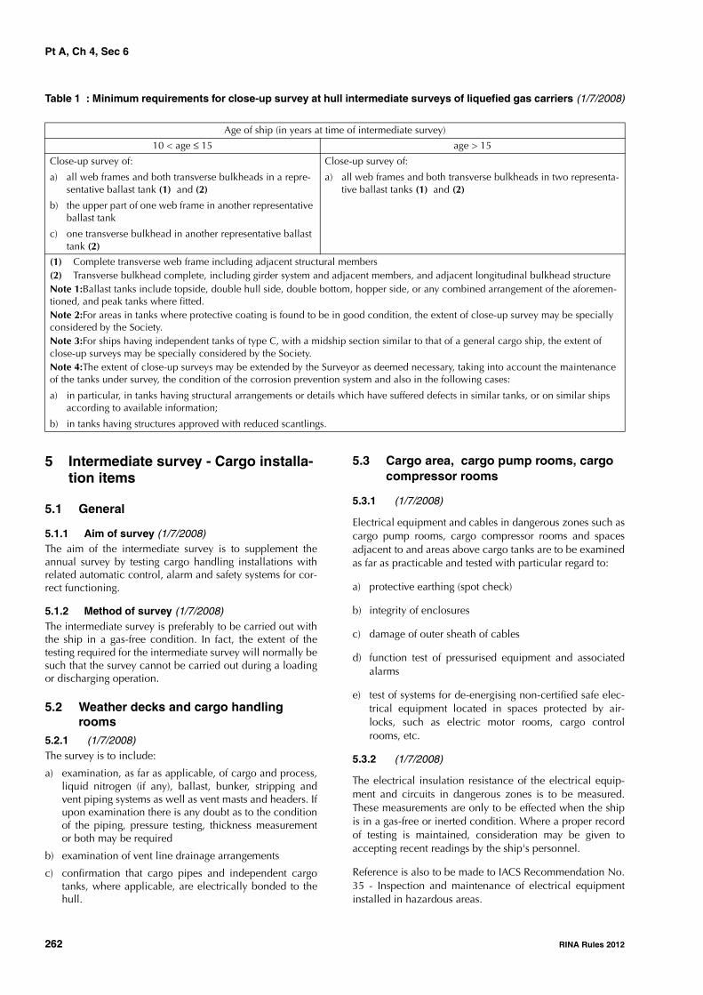
Pt A, Ch 4, Sec 6
262 RINA Rules 2012
Table 1 : Minimum requirements for close-up survey at hull intermediate surveys of liquefied gas carriers (1/7/2008)
5 Intermediate survey - Cargo installa-tion items
5.1 General
5.1.1 Aim of survey (1/7/2008)The aim of the intermediate survey is to supplement theannual survey by testing cargo handling installations withrelated automatic control, alarm and safety systems for cor-rect functioning.
5.1.2 Method of survey (1/7/2008)The intermediate survey is preferably to be carried out withthe ship in a gas-free condition. In fact, the extent of thetesting required for the intermediate survey will normally besuch that the survey cannot be carried out during a loadingor discharging operation.
5.2 Weather decks and cargo handling rooms
5.2.1 (1/7/2008)The survey is to include:
a) examination, as far as applicable, of cargo and process,liquid nitrogen (if any), ballast, bunker, stripping andvent piping systems as well as vent masts and headers. Ifupon examination there is any doubt as to the conditionof the piping, pressure testing, thickness measurementor both may be required
b) examination of vent line drainage arrangements
c) confirmation that cargo pipes and independent cargotanks, where applicable, are electrically bonded to thehull.
5.3 Cargo area, cargo pump rooms, cargo compressor rooms
5.3.1 (1/7/2008)
Electrical equipment and cables in dangerous zones such ascargo pump rooms, cargo compressor rooms and spacesadjacent to and areas above cargo tanks are to be examinedas far as practicable and tested with particular regard to:
a) protective earthing (spot check)
b) integrity of enclosures
c) damage of outer sheath of cables
d) function test of pressurised equipment and associatedalarms
e) test of systems for de-energising non-certified safe elec-trical equipment located in spaces protected by air-locks, such as electric motor rooms, cargo controlrooms, etc.
5.3.2 (1/7/2008)
The electrical insulation resistance of the electrical equip-ment and circuits in dangerous zones is to be measured.These measurements are only to be effected when the shipis in a gas-free or inerted condition. Where a proper recordof testing is maintained, consideration may be given toaccepting recent readings by the ship's personnel.
Reference is also to be made to IACS Recommendation No.35 - Inspection and maintenance of electrical equipmentinstalled in hazardous areas.
Age of ship (in years at time of intermediate survey)
10 < age ≤ 15 age > 15
Close-up survey of:
a) all web frames and both transverse bulkheads in a repre-sentative ballast tank (1) and (2)
b) the upper part of one web frame in another representative ballast tank
c) one transverse bulkhead in another representative ballast tank (2)
Close-up survey of:
a) all web frames and both transverse bulkheads in two representa-tive ballast tanks (1) and (2)
(1) Complete transverse web frame including adjacent structural members(2) Transverse bulkhead complete, including girder system and adjacent members, and adjacent longitudinal bulkhead structureNote 1:Ballast tanks include topside, double hull side, double bottom, hopper side, or any combined arrangement of the aforemen-tioned, and peak tanks where fitted.Note 2:For areas in tanks where protective coating is found to be in good condition, the extent of close-up survey may be specially considered by the Society.Note 3:For ships having independent tanks of type C, with a midship section similar to that of a general cargo ship, the extent of close-up surveys may be specially considered by the Society.Note 4:The extent of close-up surveys may be extended by the Surveyor as deemed necessary, taking into account the maintenance of the tanks under survey, the condition of the corrosion prevention system and also in the following cases:
a) in particular, in tanks having structural arrangements or details which have suffered defects in similar tanks, or on similar ships according to available information;
b) in tanks having structures approved with reduced scantlings.

Pt A, Ch 4, Sec 6
RINA Rules 2012 263
5.3.3 (1/7/2011)In addition to the requirements of [5.3.1] and [5.3.2], thesurvey also consists of:
a) confirmation that the cargo heating/cooling system is insatisfactory condition
b) confirmation that the heating system of the hull struc-ture is in satisfactory working condition
c) general examination and test of leakage detection sys-tems in interbarrier and hold spaces
d) confirmation that spares are provided for cargo areamechanical ventilation fans.
5.4 Instrumentation and safety devices5.4.1 (1/7/2008)The survey is to include:
a) examination of the installed pressure gauging systemson cargo discharge lines, cargo tanks, holds and insula-tion spaces and associated alarms
b) examination of the cargo tank liquid level gauges andhigh level alarms as well as automatic shut-off systems
c) examination of the temperature indicating equipment ofthe cargo containment system and associated alarms
d) test of the above-mentioned instrumentation by chang-ing pressure, level and temperature as applicable andcomparing with test instruments. Simulated tests may beaccepted for sensors which are not accessible or locatedwithin cargo tanks or inerted hold spaces. The test is toinclude alarm and safety functions
e) examination, as far as practicable, of the piping of thegas detection system for corrosion and damage. Theintegrity of the suction lines between suction points andanalysing units is to be verified as far as possible
f) calibration of gas detectors or verification thereof withsample gases
g) confirmation of the availability and suitability of theportable gas detection equipment and instruments formeasuring oxygen levels
h) test of the manually operated emergency shutdown sys-tem (without flow in the pipelines) to verify that the sys-tem will cause the cargo pumps and compressors tostop.
5.4.2 (1/7/2008)The instrumentation and safety systems for burning cargo asfuel are to be examined in accordance with the require-ments indicated in [5.4.1].
5.5 Inert gas system5.5.1 (1/7/2008)For ships over 10 years old at the time of the intermediatesurvey due date, if an inert gas system such as that installedon board oil tankers is fitted, the requirements given inSec 3, [5.2] for intermediate survey of oil tankers are to becomplied with.
5.5.2 (1/7/2008)In the case of low temperature liquid nitrogen storage, theplant and its associated arrangements for protecting the hull
structure against liquid nitrogen leakage are to be exam-ined.
6 Class renewal survey - Hull items
6.1 Schedule
6.1.1 Survey planning meeting (1/7/2008)A survey planning meeting is to be held prior to the com-mencement of the survey.
6.2 Scope of survey
6.2.1 General (1/7/2008)In addition to the requirements of annual surveys, the classrenewal survey is to include examination, tests and checksof sufficient extent to ensure that the hull and related pip-ing, as required in [6.2.3], are in satisfactory condition andfit for the intended purpose for the new period of class of 5years to be assigned, subject to proper maintenance andoperation and to periodical surveys being carried out at thedue dates.
6.2.2 Tanks, spaces and areas (1/7/2008)Ballast tanks, including double bottom tanks, pump rooms,compressor rooms, pipe tunnels, cofferdams and voidspaces bounding cargo tanks, decks and outer hull are to beexamined, and this examination is to be supplemented bythickness measurement and testing, as required in [6.4] and[6.5], to ensure that the structural integrity remains effec-tive.
The aim of the examination is to discover substantial corro-sion, significant deformation, fractures, damage or otherstructural deterioration that may be present.
6.2.3 Piping (1/7/2008)All piping systems within the above spaces, except thoserelated to cargo installations, for which reference is to bemade to [7.3], are to be examined and operationally testedto working pressure to the attending Surveyor's satisfactionto ensure that tightness and condition remain satisfactory.
6.2.4 Ballast tanks converted to void spaces (1/7/2008)
The extent of the survey of ballast tanks converted to voidspaces is to be specially considered in relation to therequirements for ballast tanks.Note 1: For survey of automatic air pipes, refer to Ch 3, Sec 5,[2.2.5].
Note 2: For examination of automatic air pipe heads, reference isto be made to the requirements given in Ch 3, Sec 5, Tab 4.
6.2.5 Dry-docking survey (1/7/2008)The class renewal survey is to include a bottom survey indry condition as laid down in Ch 3, Sec 6, [2.2.1]. Theoverall and close-up surveys and thickness measurements,as applicable, of the lower portions of the ballast tanks areto be carried out in accordance with the applicable require-ments for class renewal surveys, if not already performed.Note 1: Lower portions of the ballast tanks are considered to be theparts below the light ballast waterline.

Pt A, Ch 4, Sec 6
264 RINA Rules 2012
6.2.6 Ballast tank protection (1/7/2008)
The condition of the corrosion prevention system of ballasttanks, where provided, is to be examined.
For tanks used for water ballast, excluding double bottomtanks, where a hard protective coating is found in poor con-dition and it is not renewed, where soft or semi-hard coat-ing has been applied, or where a hard protective coatinghas not been applied since the time of construction, thetanks in question are to be examined at annual surveys.Thickness measurements are to be carried out as deemednecessary by the Surveyor.
When such breakdown of hard protective coating is foundin water ballast double bottom tanks and it is not renewed,where a soft or semi-hard coating has been applied, orwhere a hard protective coating has not been applied sincethe time of construction, the tanks in question may beexamined at annual surveys. When considered necessaryby the Surveyor, or where extensive corrosion exists, thick-ness measurements are to be carried out.
6.2.7 Special consideration (1/7/2008)
Where the hard protective coating in ballast tanks is foundto be in a good condition, the extent of close-up surveysand thickness measurements may be specially considered.
6.3 Extent of overall and close-up surveys
6.3.1 Overall surveys (1/7/2008)
An overall survey of all tanks and spaces, excluding fuel oil,lube oil and fresh water tanks, is to be carried out at eachclass renewal survey.
Note 1: For fuel oil, lube oil and fresh water tanks, reference is tobe made to the requirements given in Ch 3, Sec 5, [2.4.1].
6.3.2 Close-up surveys (1/7/2008)
The minimum requirements for close-up surveys at classrenewal survey are given in Tab 2.
6.3.3 Expansion of close-up surveys (1/7/2008)
The Surveyor may extend the close-up survey as deemednecessary taking into account the maintenance of the tanksunder survey, the condition of the corrosion prevention sys-tem and where tanks have structural arrangements or detailswhich have suffered defects in similar spaces or on similarships according to available information.
6.3.4 Special consideration (1/7/2008)
For areas in tanks where hard protective coatings are foundto be in a good condition, the extent of close-up surveysaccording to Tab 2 may be specially considered.
6.4 Extent of thickness measurements
6.4.1 Minimum requirements (1/7/2008)
The minimum requirements for thickness measurements atclass renewal survey are given in Tab 3.
6.4.2 Expansion of thickness measurements (1/7/2008)
The Surveyor may extend the thickness measurements asdeemed necessary. When thickness measurements indicatesubstantial corrosion, the extent of such measurements is tobe increased to determine the extent of areas of substantialcorrosion. Tab 4 may be used as guidance for these addi-tional thickness measurements.
6.4.3 Special consideration (1/7/2008)
For areas in tanks where hard protective coatings are foundto be in a good condition, the extent of thickness measure-ment according to Tab 3 may be specially considered.
6.4.4 Choice of transverse sections (1/7/2008)
Transverse sections are to be chosen where the largestreductions are suspected to occur or are revealed from deckplating measurements.
6.5 Extent of tank testing
6.5.1 Testing requirements (1/7/2008)
All boundaries of water ballast tanks and deep tanks usedfor water ballast within the cargo area are to be pressuretested. For fuel oil tanks, representative tanks are to be pres-sure tested.
6.5.2 Expansion of tank testing (1/7/2008)
The Surveyor may extend the tank testing as deemed neces-sary.
6.5.3 Method of tank testing (1/7/2008)
Tank testing of fuel oil tanks is to be carried out with a headof liquid to the highest point that liquid will rise to underservice conditions. Tank testing of fuel oil tanks may be spe-cially considered based on a satisfactory external examina-tion of the tank boundaries, and a confirmation from theMaster stating that the pressure testing has been carried outaccording to the requirements with satisfactory results.
6.6 Emergency towing arrangement
6.6.1 (1/7/2008)
The survey is to include:
a) an examination of the emergency towing arrangement
b) confirmation that the arrangement is readily availablewith aft towing arrangement pre-rigged and forwardchafing gear secured to the strong-point
c) an examination of the pick-up gear, towing pennant andchafing gear over the full length for possible deteriora-tion. Where the pennant line is stored in a watertightcondition and can be confirmed as being maintained,consideration may be given to waiving the requirementto examine the pennant line over the full length
d) an examination of the strong-points, fairleads and ped-estal roller together with their attachments to the hullstructure.

Pt A, Ch 4, Sec 6
RINA Rules 2012 265
Table 2 : Minimum requirements for close-up survey at class renewal surveys of liquefied gas carriers (1/7/2008)
Table 3 : Minimum requirements for thickness measurements at class renewal surveys of liquefied gas carriers (1/7/2008)
Age of ship (in years at time of class renewal survey due date)
age ≤ 5 5 < age ≤ 10 age > 10
One web frame in a representative ballast tank of the topside, hopper side and double hull side type (1)
One transverse bulkhead in a bal-last tank (3)
All web frames in a ballast tank, which is to be a double hull side tank or a topside tank. If such tanks are not fitted, another ballast tank is to be selected (1)
One web frame in each remaining ballast tank (1)
One transverse bulkhead in each ballast tank (2)
All web frames in all ballast tanks (1)
All transverse bulkheads in all ballast tanks (2)
(1) Complete transverse web frame including adjacent structural members(2) Transverse bulkhead complete, including girder system and adjacent members, and adjacent longitudinal bulkhead structure(3) Transverse bulkhead lower part including girder system and adjacent structural membersNote 1: Ballast tanks include topside, double hull side, double bottom, hopper side, or any combined arrangement of the aforemen-tioned, and peak tanks where fitted.Note 2: For areas in tanks where coatings are found to be in good condition, as defined in Ch 2, Sec 2, [2.2.11], the extent of close-up surveys may be specially considered by the Society.Note 3: For ships having independent tanks of type C, with a midship section similar to that of a general cargo ship, the extent of close-up surveys may be specially considered by the Society.Note 4: The Surveyor may extend the close-up survey as deemed necessary, taking into account the maintenance of the tanks under survey, the condition of the corrosion prevention system and also in the following cases:
a) in particular, in tanks having structural arrangements or details which have suffered defects in similar tanks, or on similar ships according to available information;
b) in tanks having structures approved with reduced scantlings.
Age of ship (in years at time of class renewal survey due date)
age ≤ 5 5 < age ≤ 10 10 < age ≤ 15 age > 15
Suspect areas Suspect areas Suspect areas Suspect areas
One section of deck plating for the full beam of the ship within 0,5 L amidships in way of a ballast tank, if any
Within the cargo area: • each deck plate• b)one transverse section
within 0,5 L amidships in way of a ballast tank, if any
Within the cargo area:• each deck plate • two transverse sections (1) • all wind and water strakes
Within the cargo area: • each deck plate • three transverse sections
(1)• each bottom plate • duct keel plating and inter-
nals
Selected wind and water strakes outside the cargo area
Selected wind and water strakes outside the cargo area
All wind and water strakes, full length
Measurements, for general assessment and recording of corrosion pattern, of those structural members subject to close-up survey according to Tab 2
Measurements, for general assessment and recording of corrosion pattern, of those structural members subject to close-up survey according to Tab 2
Measurements, for general assessment and recording of corrosion pattern, of those structural members subject to close-up survey according to Tab 2
Measurements, for general assessment and recording of corrosion pattern, of those structural members subject to close-up survey according to Tab 2
(1) At least one section is to be within 0,5 L amidships and, where applicable, in way of a ballast tank.Note 1:For ships having independent tanks of type C, with a midship section similar to that of a general cargo ship, the extent of thickness measurements may be increased to include the tank top plating at the discretion of the Surveyor.Note 2:For areas in spaces where coatings are found to be in good condition, the extent of thickness measurements may be spe-cially considered by the Society.Note 3:The Surveyor may extend the thickness measurements as deemed necessary. When thickness measurements indicate sub-stantial corrosion, the extent of such measurements is to be increased to determine the extent of areas of substantial corrosion. Tab 4 may be used as guidance for these additional thickness measurements.
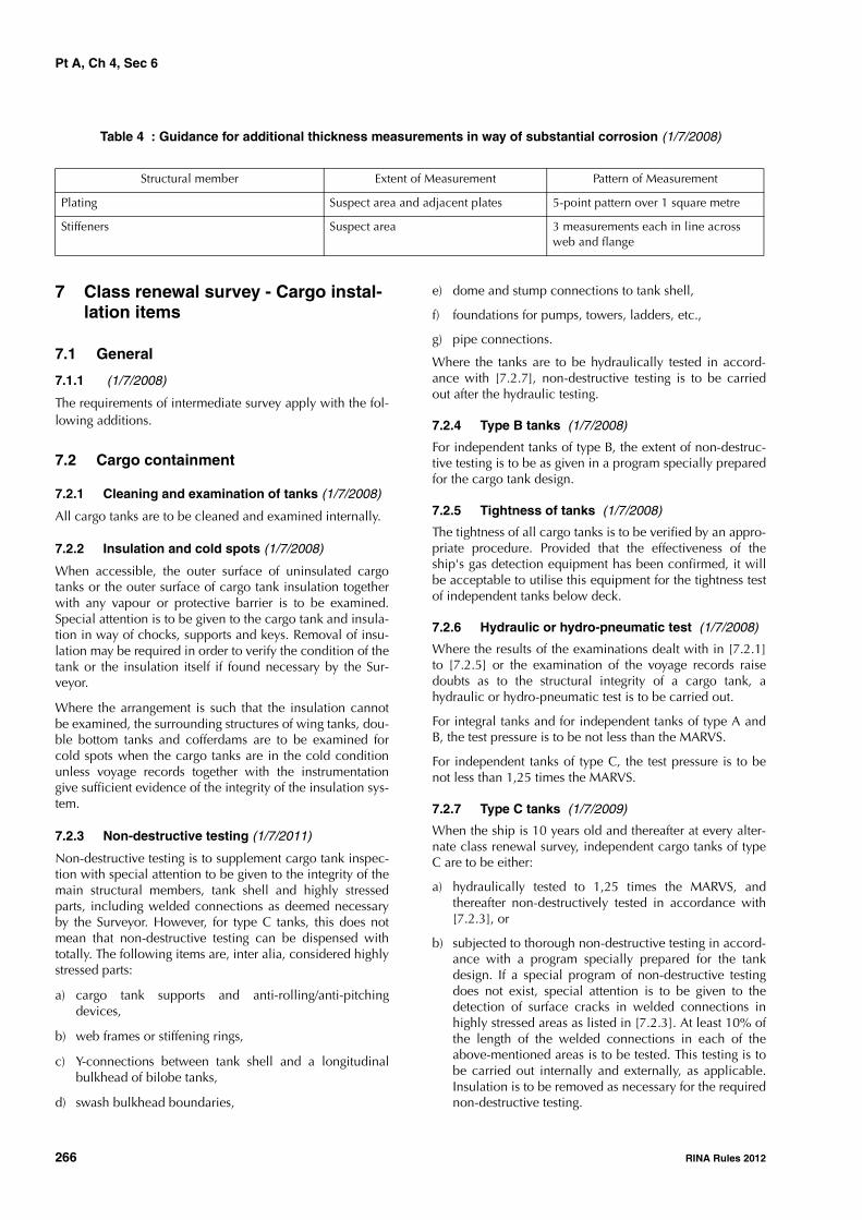
Pt A, Ch 4, Sec 6
266 RINA Rules 2012
Table 4 : Guidance for additional thickness measurements in way of substantial corrosion (1/7/2008)
7 Class renewal survey - Cargo instal-lation items
7.1 General
7.1.1 (1/7/2008)
The requirements of intermediate survey apply with the fol-lowing additions.
7.2 Cargo containment
7.2.1 Cleaning and examination of tanks (1/7/2008)
All cargo tanks are to be cleaned and examined internally.
7.2.2 Insulation and cold spots (1/7/2008)
When accessible, the outer surface of uninsulated cargotanks or the outer surface of cargo tank insulation togetherwith any vapour or protective barrier is to be examined.Special attention is to be given to the cargo tank and insula-tion in way of chocks, supports and keys. Removal of insu-lation may be required in order to verify the condition of thetank or the insulation itself if found necessary by the Sur-veyor.
Where the arrangement is such that the insulation cannotbe examined, the surrounding structures of wing tanks, dou-ble bottom tanks and cofferdams are to be examined forcold spots when the cargo tanks are in the cold conditionunless voyage records together with the instrumentationgive sufficient evidence of the integrity of the insulation sys-tem.
7.2.3 Non-destructive testing (1/7/2011)
Non-destructive testing is to supplement cargo tank inspec-tion with special attention to be given to the integrity of themain structural members, tank shell and highly stressedparts, including welded connections as deemed necessaryby the Surveyor. However, for type C tanks, this does notmean that non-destructive testing can be dispensed withtotally. The following items are, inter alia, considered highlystressed parts:
a) cargo tank supports and anti-rolling/anti-pitchingdevices,
b) web frames or stiffening rings,
c) Y-connections between tank shell and a longitudinalbulkhead of bilobe tanks,
d) swash bulkhead boundaries,
e) dome and stump connections to tank shell,
f) foundations for pumps, towers, ladders, etc.,
g) pipe connections.
Where the tanks are to be hydraulically tested in accord-ance with [7.2.7], non-destructive testing is to be carriedout after the hydraulic testing.
7.2.4 Type B tanks (1/7/2008)
For independent tanks of type B, the extent of non-destruc-tive testing is to be as given in a program specially preparedfor the cargo tank design.
7.2.5 Tightness of tanks (1/7/2008)
The tightness of all cargo tanks is to be verified by an appro-priate procedure. Provided that the effectiveness of theship's gas detection equipment has been confirmed, it willbe acceptable to utilise this equipment for the tightness testof independent tanks below deck.
7.2.6 Hydraulic or hydro-pneumatic test (1/7/2008)
Where the results of the examinations dealt with in [7.2.1]to [7.2.5] or the examination of the voyage records raisedoubts as to the structural integrity of a cargo tank, ahydraulic or hydro-pneumatic test is to be carried out.
For integral tanks and for independent tanks of type A andB, the test pressure is to be not less than the MARVS.
For independent tanks of type C, the test pressure is to benot less than 1,25 times the MARVS.
7.2.7 Type C tanks (1/7/2009)
When the ship is 10 years old and thereafter at every alter-nate class renewal survey, independent cargo tanks of typeC are to be either:
a) hydraulically tested to 1,25 times the MARVS, andthereafter non-destructively tested in accordance with[7.2.3], or
b) subjected to thorough non-destructive testing in accord-ance with a program specially prepared for the tankdesign. If a special program of non-destructive testingdoes not exist, special attention is to be given to thedetection of surface cracks in welded connections inhighly stressed areas as listed in [7.2.3]. At least 10% ofthe length of the welded connections in each of theabove-mentioned areas is to be tested. This testing is tobe carried out internally and externally, as applicable.Insulation is to be removed as necessary for the requirednon-destructive testing.
Structural member Extent of Measurement Pattern of Measurement
Plating Suspect area and adjacent plates 5-point pattern over 1 square metre
Stiffeners Suspect area 3 measurements each in line across web and flange

Pt A, Ch 4, Sec 6
RINA Rules 2012 267
7.2.8 Hold spaces and secondary barriers (1/7/2008)
As far as accessible, all hold spaces and hull insulation (ifprovided), secondary barriers and tank supporting structuresare to be visually examined.
The secondary barrier of tanks is to be checked for its effec-tiveness by means of a pressure/vacuum test, a visual exam-ination or any other acceptable method.
7.2.9 Membrane and semi-membrane systems (1/7/2008)
a) For membrane and semi-membrane tanks systems,inspection and testing are to be carried out in accord-ance with programs specially prepared in accordancewith an approved method for the actual tank system.
b) For membrane containment systems, a tightness test ofthe secondary barrier is to be carried out in accordancewith the system Designers' procedures as approved bythe Society.
c) For membrane containment systems with glued second-ary barriers, the values obtained are to be comparedwith previous results or results obtained at new buildingstage. If significant differences are observed for eachtank or between tanks, the Surveyor will require an eval-uation and additional testing as necessary.
7.2.10 Gas-tight bulkheads (1/7/2008)All gas-tight bulkheads are to be examined and the effec-tiveness of gas-tight shaft sealing is to be verified.
7.2.11 Tanks electrically bonded (1/7/2008)It is to be verified that independent cargo tanks are electri-cally bonded to the hull.
7.2.12 Pressure relief valves (1/7/2008)Pressure relief valves for cargo tanks are to be opened forexamination, adjusted, function tested and sealed. If thecargo tanks are equipped with relief valves with non-metal-lic membranes in the main or pilot valves, these non-metal-lic membranes are to be replaced. Where a proper record ofcontinuous overhaul and re-testing of individually identifia-ble relief valves is maintained, consideration may be givento acceptance on the basis of opening, internal examinationand testing of a representative sample of valves, includingeach size and type of liquefied gas or vapour relief valves inuse, provided there is evidence in the log-book that theremaining valves have been overhauled and tested sincecrediting of the previous class renewal survey.
7.2.13 Pressure/vacuum relief valves (1/7/2008)Pressure/vacuum relief valves, rupture disc and other pres-sure relief devices for interbarrier spaces and hold spacesare to be opened, examined, tested and readjusted as nec-essary, depending on their design.
7.3 Piping systems7.3.1 (1/7/2008)Cargo, liquid nitrogen (if any), process, stripping and vent-ing piping systems, including valves, actuators, compensa-tors, etc. are to be opened for examination as deemednecessary. Insulation is to be removed as deemed necessaryto ascertain the condition of the pipes. If the visual exami-
nation raises doubt as to the integrity of the pipelines, apressure test at 1,25 times the MARVS for the pipeline is tobe carried out. After reassembly the complete piping sys-tems are to be tested for leaks.
7.3.2 (1/7/2008)It is to be verified that all cargo piping systems are electri-cally bonded to the hull.
7.3.3 (1/7/2008)Pressure relief valves on cargo piping are to be functiontested. A random selection of valves is to be opened forexamination and adjusted.
7.3.4 (1/7/2008)Vent line drainage arrangements are to be examined.
7.4 Cargo area, cargo pump rooms, cargo compressor rooms
7.4.1 Examination of spaces (1/7/2008)All cargo pump room, compressor room and control roomboundaries are to be generally examined. Gas-tight shaftsealing devices are to be examined. The bottom of cargopump rooms and cargo compressor rooms is to be pre-sented clean for the examination of stripping devices andgutters.
7.4.2 Examination of pumps (1/7/2008)Ballast and stripping pumps are to be internally examinedand prime movers checked. A working test is to be carriedout.
Maintenance records of cargo pumps are to be made availa-ble to the Surveyor.
7.4.3 Electrical equipment in dangerous zones (1/7/2008)
Electrical equipment and cables in dangerous zones such ascargo pump rooms, cargo compressor rooms and spacesadjacent to and areas above cargo tanks are to be examinedas far as practicable and tested with particular regard to:
a) protecting earthing (spot check)
b) integrity of enclosures
c) damage of outer sheath of cables
d) function testing of pressurised equipment and associ-ated alarms
e) testing of systems for de-energising non-certified safeelectrical equipment located in spaces protected by air-locks, such as electric motor rooms, cargo controlrooms, etc.
7.4.4 Measurement of electrical insulation (1/7/2008)
The electrical insulation resistance of the electrical equip-ment and circuits in dangerous zones is to be measured.These measurements are only to be effected when the shipis in a gas-free or inerted condition. Where a proper recordof testing is maintained, consideration may be given toaccepting recent readings by the ship's personnel.
Reference is also to be made to IACS Recommendation No.35 - Inspection and maintenance of electrical equipmentinstalled in hazardous areas.
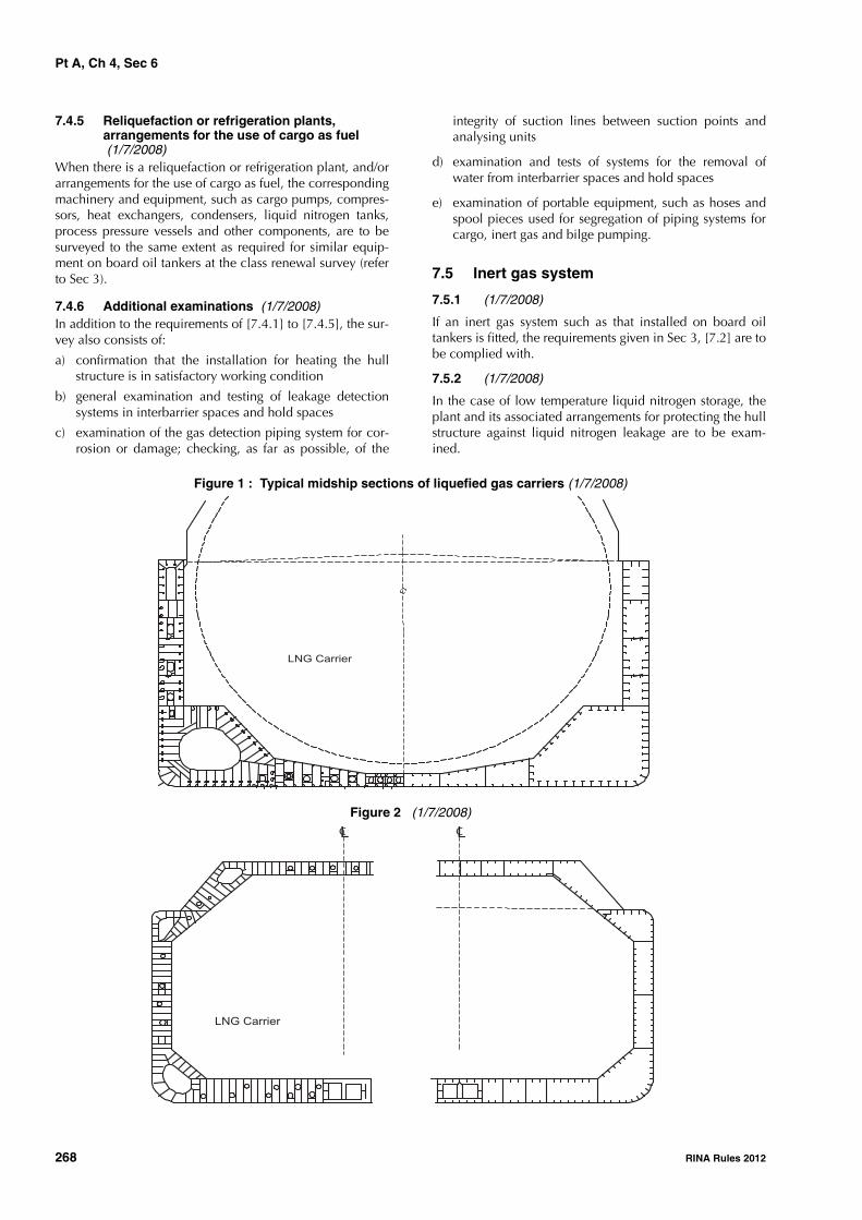
Pt A, Ch 4, Sec 6
268 RINA Rules 2012
7.4.5 Reliquefaction or refrigeration plants, arrangements for the use of cargo as fuel (1/7/2008)
When there is a reliquefaction or refrigeration plant, and/orarrangements for the use of cargo as fuel, the correspondingmachinery and equipment, such as cargo pumps, compres-sors, heat exchangers, condensers, liquid nitrogen tanks,process pressure vessels and other components, are to besurveyed to the same extent as required for similar equip-ment on board oil tankers at the class renewal survey (referto Sec 3).
7.4.6 Additional examinations (1/7/2008)In addition to the requirements of [7.4.1] to [7.4.5], the sur-vey also consists of:
a) confirmation that the installation for heating the hullstructure is in satisfactory working condition
b) general examination and testing of leakage detectionsystems in interbarrier spaces and hold spaces
c) examination of the gas detection piping system for cor-rosion or damage; checking, as far as possible, of the
integrity of suction lines between suction points andanalysing units
d) examination and tests of systems for the removal ofwater from interbarrier spaces and hold spaces
e) examination of portable equipment, such as hoses andspool pieces used for segregation of piping systems forcargo, inert gas and bilge pumping.
7.5 Inert gas system
7.5.1 (1/7/2008)
If an inert gas system such as that installed on board oiltankers is fitted, the requirements given in Sec 3, [7.2] are tobe complied with.
7.5.2 (1/7/2008)
In the case of low temperature liquid nitrogen storage, theplant and its associated arrangements for protecting the hullstructure against liquid nitrogen leakage are to be exam-ined.
Figure 1 : Typical midship sections of liquefied gas carriers (1/7/2008)
Figure 2 (1/7/2008)
LNG Carrier
LNG Carrier
LC LC

Pt A, Ch 4, Sec 6
RINA Rules 2012 269
Figure 3 (1/7/2008)
Figure 4 (1/7/2008)
LPG Carrier
Lc Lc
x
LPG Carrier

Pt A, Ch 4, Sec 7
270 RINA Rules 2012
SECTION 7 RO-RO CARGO SHIPS, PASSENGER SHIPS,RO-RO PASSENGER SHIPS
1 General
1.1
1.1.1 The requirements of this Section are applicable afterconstruction to all self-propelled ships which have beenassigned one of the following service notations:
• ro-ro cargo ship
• passenger ship
• ro-ro passenger ship.
1.1.2 These requirements are additional to those laiddown in Chapter 3, according to the relevant surveys.
1.1.3 Periodical lightweight checkAt periodical intervals not exceeding five years, a light-weight survey is to be carried out on all ships having theservice notation passenger ship or ro-ro passenger ship toverify any changes in lightship displacement and longitudi-nal centre of gravity. The ship is to be re-inclined whenever,in comparison with the approved stability information, adeviation from the lightship displacement exceeding 2% ora deviation of the longitudinal centre of gravity exceeding1% of L is found, or anticipated.
1.2 Application
1.2.1 General (1/1/2012)The survey requirements in [2.1], [3.1] and [6.1] for annualand renewal survey are applicable to the survey of bow,inner, side shell and stern doors of ro-ro passenger shipsand ro-ro cargo ships, to the extent appropriate to thearrangement and equipment of each ship.
1.2.2 Special consideration (1/1/2012)
Special consideration may be given in application of rele-vant requirements of this Section to commercial vesselsowned or chartered by Governments, which are utilised insupport of military operations or service.
1.3 Definitions
1.3.1 General (1/1/2012)
For the purpose of the survey requirements for shell andinner doors laid down in [2.1], [3.1] and [6.1] for annualand renewal survey for ro-ro cargo ships and ro-ro passen-ger ships, the following definitions are given.
1.3.2 Ro-ro ship (1/1/2012)
A ro-ro ship is a ship which utilises a loading ramp to ena-ble wheeled vehicles to be rolled on and rolled off the ship.
1.3.3 Ro-ro passenger ship (1/1/2012)A ro-ro passenger ship is a passenger ship with ro-ro spacesor special category spaces.
1.3.4 Ro-ro spaces (1/1/2012)Ro-ro spaces are spaces not normally subdivided in anyway and normally extending to either a substantial length orthe entire length of the ship, in which motor vehicles withfuel in their tanks for their own propulsion and/or goods(packaged or in bulk, in or on rail or road cars, vehicles(including road or rail tankers), trailers, containers, pallets,demountable tanks or in or on similar stowage units or,other receptacles) can be loaded and unloaded normally ina horizontal direction.
1.3.5 Special category spaces (1/1/2012)Special category spaces are those enclosed vehicle spacesabove or below the bulkhead deck, into and from whichvehicles can be driven and to which passengers haveaccess. Special category spaces may be accommodated onmore than one deck provided that the total overall clearheight for vehicles does not exceed 10 m.
1.3.6 Securing device (1/1/2012)A securing device is a device used to keep the door closedby preventing it from rotating about its hinges.
1.3.7 Supporting device (1/1/2012)A supporting device is a device used to transmit external orinternal loads from the door to a securing device and fromthe securing device to the ship's structure, or a device otherthan a securing device, such as a hinge, stopper or otherfixed device, that transmits loads from the door to the ship'sstructure.
1.3.8 Locking device (1/1/2012)A locking device is a device that locks a securing device inthe closed position.
1.3.9 Close-up survey (1/1/2012)A close-up survey is a survey where the details of structuralcomponents are within the close visual inspection range ofthe Surveyor, i.e. normally within reach of hand.
2 Ro-ro cargo ships - Annual survey
2.1 Shell and inner doors
2.1.1 Scope of survey (1/1/2012)The survey is to consist of an examination to verify, as far asis practicable, that the bow, inner, side shell and stern doorsare maintained in a satisfactory condition.
Pt A, Ch 4, Sec 7
RINA Rules 2012 271
2.1.2 Unapproved changes (1/1/2012)
Confirmation is to be obtained that no unapproved changeshave been made to the bow, inner, side shell and sterndoors since the last survey.
2.1.3 Documents (1/1/2012)
If an Operating and Maintenance Manual (OMM) isrequired, it is to be verified that an approved copy is onboard and any possible modifications are included.
It is to be verified that documented operating procedures forclosing and securing doors are kept on board and posted atan appropriate place.
The Surveyor is to examine the OMM with special attentionto the register of inspections and its contents as a basis forthe survey.
2.1.4 Structural examination (1/1/2012)
Bow, inner, side shell and stern doors are to be examinedwith particular attention paid to:
a) structural arrangement of doors including plating, sec-ondary stiffeners, primary structure, hinging arms andwelding;
b) shell structure surrounding the opening of the doors andthe securing, supporting and locking devices includingshell plating, secondary stiffeners, primary structure andwelding;
c) hinges and bearings, thrust bearings;
d) hull and door side supports for securing, supporting andlocking devices;
e) close-up survey of securing, supporting and lockingdevices including welding, in accordance with therequirements given in Tab 1.
Whenever a crack is found, an examination with NDT is tobe carried out in the surrounding area and for similar itemsas considered necessary by the Surveyor.
2.1.5 Measurement of clearances (1/1/2012)
Clearances of hinges, bearings and thrust bearings are to betaken, where no dismantling is required. Where the func-tion test is not satisfactory, dismantling may be required tomeasure the clearances. If dismantling is carried out, a vis-ual examination of hinge pins and bearings together withNDT of the hinge pin is to be carried out. Clearances ofsecuring, supporting and locking devices are to be meas-ured, where indicated in the OMM.
2.1.6 Sealing arrangement (1/1/2012)
An examination of packing material/rubber gaskets andretaining bars or channels, including welding, is to be car-ried out.
2.1.7 Drainage arrangement (1/1/2012)
An examination of drainage arrangement, including bilgewells and drain pipes, where fitted, is to be carried out. Atest of the bilge system between the inner and outer doors isto be carried out.
2.1.8 Function test of doors (1/1/2012)A check of the satisfactory operation of the bow, inner, sideshell and stern doors during a complete opening and clos-ing operation is to be made, as applicable, including:
a) proper working of the hinging arms and hinges;
b) proper engagement of the thrust bearings;
c) device for locking the door in the open position;
d) securing, supporting and locking devices;
e) proper sequence of the interlock system for the open-ing/closing system and the securing and lockingdevices;
f) mechanical lock of the securing devices;
g) proper locking of hydraulic securing devices in theevent of a loss of the hydraulic fluid, according to theprocedure provided by the OMM;
h) correct indication of open/closed position of doors andsecuring/locking devices at navigation bridge and othercontrol stations;
i) isolation of the hydraulic securing/locking devices fromother hydraulic systems;
j) confirmation that the operating panels are inaccessibleto unauthorised persons;
k) verification that a notice plate giving instructions to theeffect that all securing devices are to be closed andlocked before leaving harbour is placed at each operat-ing panel and supplemented by warning indicatorlights;
l) examination of electrical equipment for opening, clos-ing and securing the doors.
2.1.9 Function test of the indicator system (1/1/2012)
A check of the satisfactory operation of the indicator sys-tem, where fitted, is to be carried out, as applicable, includ-ing:
a) proper visible indication and audible alarm on the navi-gation bridge panel, according to the selected function"harbour/sea voyage" and on the operating panel;
b) lamp test function on both panels;
c) verification that it is not possible to turn off the indicatorlight on both panels;
d) verification of fail-safe performance, according to theprocedure provided by the OMM;
e) confirmation that power supply for the indicator systemis supplied by the emergency source or other securepower supply and independent of the power supply foroperating the doors;
f) proper condition of sensors and protection from water,ice formation and mechanical damage.
2.1.10 Test of water leakage detection system (1/1/2012)
Where fitted, the water leakage detection system is to betested including proper audible alarm on the navigationbridge panel and on the engine control room panel, accord-ing to the procedure provided by the OMM.

Pt A, Ch 4, Sec 7
272 RINA Rules 2012
2.1.11 Test of television surveillance system (1/1/2012)
Where fitted, the television surveillance system is to betested including proper indication on the navigation bridgemonitor and on the engine control room monitor.
2.1.12 Tightness test (1/1/2012)
A hose test or equivalent is to be carried out. If the visualexamination and function test have shown satisfactoryresults, the tightness test of shell doors on ro-ro cargo shipsneed not be carried out unless considered necessary by theattending Surveyor.
2.1.13 NDT and thickness measurements (1/1/2012)
When considered necessary by the Surveyor, NDT andthickness measurements may be required after visual exam-ination and function test.
2.2 Internal platforms and ramps
2.2.1 The annual survey of internal movable platforms andramps (excluding those considered as inner doors and cov-ered in [2.1]) and related equipment consists of:
• a general examination of the installation, particularattention being paid to the condition of steel cables
• confirmation of the proper operation of platforms/rampsand of mechanical stops and locks
• checking, as far as practicable, of the alarms and safetydevices.
2.3 Fire protection, detection and extinction
2.3.1 (1/1/2007)
Within the scope of survey of fire protection, detection andextinction arrangements as required for the annual survey ofall ships in Ch 3, Sec 3, [3.4], attention is to be given to theparticular arrangements related to ro-ro cargo spaces, suchas:
• fire detection systems and alarms
• low pressure CO2 fixed fire-extinguishing arrangements,if fitted
• electrical equipment of a safe type.
3 Ro-ro cargo ships - Class renewal survey
3.1 Shell and inner doors
3.1.1 Scope of survey (1/1/2012)
The class renewal survey is to include, in addition to therequirements of the annual survey as stated in [2.1], exami-nation, tests and checks of sufficient extent to verify that thebow, inner, side shell and stern doors are in satisfactorycondition and considered able to remain in compliancewith applicable requirements, subject to proper mainte-
nance and operation in accordance with the Operation andMaintenance Manual (OMM) or the Manufacturer's recom-mendations and the periodical surveys being carried out atthe due dates for the five-year period until the next classrenewal survey.
3.1.2 Thickness measurements and testing (1/1/2012)
The examinations of the doors are to be supplemented bythickness measurements and testing to verify compliancewith applicable requirements so that the structural andweathertight integrity remain effective. The aim of theexamination is to identify corrosion, significant deforma-tion, fractures, damages or other structural deterioration,that may be present.
3.1.3 Survey of doors (1/1/2012)
The bow, inner, side shell and stern doors are to be sur-veyed as follows.
a) A survey of the items listed in [2.1.4], including close-up survey of securing, supporting and locking devices,together with welding, is to be carried out in accord-ance with the requirements given in Tab 1.
b) Non-destructive testing and thickness measurements areto be carried out on securing, supporting and lockingdevices, including welding, to the extent considerednecessary by the Surveyor. Whenever a crack is found,an examination with NDT is to be carried out in the sur-rounding area and for similar items as considered nec-essary by the Surveyor.
c) The maximum thickness diminution of hinging arms,securing, supporting and locking devices is not to bemore than 15% of the as-built thickness.
d) A check of the effectiveness of sealing arrangements byhose testing or equivalent is to be carried out.
e) Clearances of hinges, bearings and thrust bearings are tobe taken. Unless otherwise specified in the OMM orrecommended by the Manufacturer, the measurement ofclearances on ro-ro cargo ships may be limited to repre-sentative bearings where dismantling is needed in orderto measure the clearances. If dismantling is carried out,a visual examination of hinge pins and bearingstogether with NDT of the hinge pin is to be carried out.
f) The non-return valves of the drainage system are to bedismantled and examined.
3.2 Internal platforms and ramps
3.2.1 The condition of pulleys, axles, cables and structureof the platforms and ramps is to be checked.
Electric motors and/or hydraulically operated equipmentare to be surveyed according to the scope detailed in Ch 3,Sec 5, [3] for the class renewal survey of machinery installa-tions.
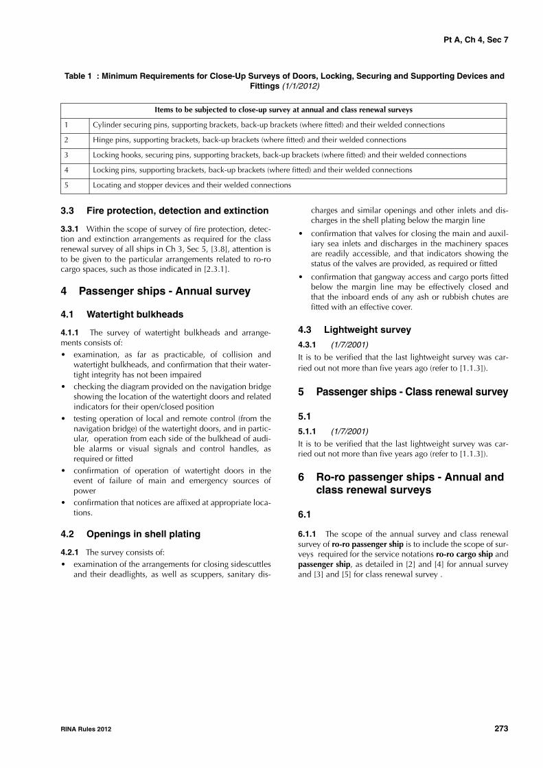
Pt A, Ch 4, Sec 7
RINA Rules 2012 273
Table 1 : Minimum Requirements for Close-Up Surveys of Doors, Locking, Securing and Supporting Devices and Fittings (1/1/2012)
3.3 Fire protection, detection and extinction
3.3.1 Within the scope of survey of fire protection, detec-tion and extinction arrangements as required for the classrenewal survey of all ships in Ch 3, Sec 5, [3.8], attention isto be given to the particular arrangements related to ro-rocargo spaces, such as those indicated in [2.3.1].
4 Passenger ships - Annual survey
4.1 Watertight bulkheads
4.1.1 The survey of watertight bulkheads and arrange-ments consists of:• examination, as far as practicable, of collision and
watertight bulkheads, and confirmation that their water-tight integrity has not been impaired
• checking the diagram provided on the navigation bridgeshowing the location of the watertight doors and relatedindicators for their open/closed position
• testing operation of local and remote control (from thenavigation bridge) of the watertight doors, and in partic-ular, operation from each side of the bulkhead of audi-ble alarms or visual signals and control handles, asrequired or fitted
• confirmation of operation of watertight doors in theevent of failure of main and emergency sources ofpower
• confirmation that notices are affixed at appropriate loca-tions.
4.2 Openings in shell plating
4.2.1 The survey consists of:• examination of the arrangements for closing sidescuttles
and their deadlights, as well as scuppers, sanitary dis-
charges and similar openings and other inlets and dis-charges in the shell plating below the margin line
• confirmation that valves for closing the main and auxil-iary sea inlets and discharges in the machinery spacesare readily accessible, and that indicators showing thestatus of the valves are provided, as required or fitted
• confirmation that gangway access and cargo ports fittedbelow the margin line may be effectively closed andthat the inboard ends of any ash or rubbish chutes arefitted with an effective cover.
4.3 Lightweight survey
4.3.1 (1/7/2001)
It is to be verified that the last lightweight survey was car-ried out not more than five years ago (refer to [1.1.3]).
5 Passenger ships - Class renewal survey
5.1
5.1.1 (1/7/2001)
It is to be verified that the last lightweight survey was car-ried out not more than five years ago (refer to [1.1.3]).
6 Ro-ro passenger ships - Annual and class renewal surveys
6.1
6.1.1 The scope of the annual survey and class renewalsurvey of ro-ro passenger ship is to include the scope of sur-veys required for the service notations ro-ro cargo ship andpassenger ship, as detailed in [2] and [4] for annual surveyand [3] and [5] for class renewal survey .
Items to be subjected to close-up survey at annual and class renewal surveys
1 Cylinder securing pins, supporting brackets, back-up brackets (where fitted) and their welded connections
2 Hinge pins, supporting brackets, back-up brackets (where fitted) and their welded connections
3 Locking hooks, securing pins, supporting brackets, back-up brackets (where fitted) and their welded connections
4 Locking pins, supporting brackets, back-up brackets (where fitted) and their welded connections
5 Locating and stopper devices and their welded connections

Pt A, Ch 4, Sec 8
274 RINA Rules 2012
SECTION 8 GENERAL DRY CARGO SHIPS
1 General
1.1 Application1.1.1 (1/7/2007)The requirements of this Section apply to all self-propelledGeneral Dry Cargo Ships 500 gt and above carrying solidcargoes other than (see Note 1):- ships subject to the provisions of Sec 2 or Sec 9- dedicated container carriers;- dedicated forest product carriers (not timber or log carri-
ers);- ro-ro cargo ships;- refrigerated cargo ships;- dedicated wood chip carriers;- dedicated cement carriers;- livestock carriers;- deck cargo ships (see Note 2).
Note 1: The requirements of [2.2.1] and [4.7.1] also apply to thosecargo ships which, although belonging to the ship types listed in[1.1.1] that are excluded from the application of this Section, arefitted with a single cargo hold.
Note 2: A "deck cargo ship" is a ship that is designed to carry cargoexclusively above deck without any access for cargo below deck.
1.1.2 (1/7/2006)The requirements apply to the surveys of the hull structureand piping systems in way of cargo holds, cofferdams, pipetunnels, void spaces and fuel oil tanks within the cargo areaand all ballast tanks. They are additional to the require-ments applicable to the remainder of the ship, given inChapter 3 according to the relevant surveys.
1.1.3 (1/7/2003)The requirements contain the minimum extent of examina-tion, thickness measurements and tank testing. When sub-stantial corrosion, as defined in Ch 2, Sec 2, [2.2.7], and/orstructural defects are found, the survey is to be extendedand is to include additional close-up surveys when neces-sary.
1.1.4 (1/7/2003)When, in any survey, thickness measurements are required:- the procedure detailed in Ch 2, Sec 2, [2.3] is to be
applied- the thickness measurement operator is to attend the sur-
vey planning meeting held prior to commencing thesurvey.
1.2 Reporting and evaluation of surveys 1.2.1 (1/7/2003)The data and information on the structural condition of theship collected during survey are evaluated for acceptabilityand structural integrity of the ship's cargo area.
1.2.2 (1/7/2003)The survey and thickness measurement reports are to beissued to the Owner and placed on board the ship for refer-ence at future surveys.
2 Annual survey
2.1 Scope
2.1.1 General (1/7/2003)The survey is to consist of an examination for the purpose ofensuring, as far as practicable, that the hull, hatch covers,coamings and piping are maintained in a satisfactory condi-tion.
2.1.2 Examination of the Hull (1/7/2003)a) Examination of the hull plating and its closing appli-
ances as far as can be seen.
b) Examination of watertight penetrations as far as practi-cable.
2.1.3 Examination of weather decks, hatch covers and coamings (1/7/2006)
a) Confirmation is to be obtained that no unapprovedchanges have been made to the hatch covers, hatchcoamings and their securing and sealing devices sincethe last survey.
b) Where mechanically operated steel covers are fitted,check of the satisfactory condition of:• hatch covers; including close-up survey of hatch
cover plating;• tightness devices of longitudinal, transverse and
intermediate cross junctions (gaskets, gasket lips,compression bars, drainage channels);
• clamping devices, retaining bars, cleating;• chain or rope pulleys;• guides;• guide rails and track wheels;• stoppers, etc.;• wires, chains, gypsies, tensioning devices;• hydraulic system essential to closing and securing;• safety locks and retaining devices.
c) Where portable covers, wooden or steel pontoons arefitted, check of the satisfactory condition, where appli-cable, of:• wooden covers and portable beams, carriers or
sockets for the portable beam, and their securingdevices;
• steel pontoons;• tarpaulins;• cleats, battens and wedges;

Pt A, Ch 4, Sec 8
RINA Rules 2012 275
• hatch securing bars and their securing devices;
• loading pads/bars and the side plate edge;
• guide plates and chocks;
• compression bars, drainage channels and drainpipes (if any).
d) Check of the satisfactory condition of hatch coamingplating and its stiffeners, including close-up survey.
e) A random check of the satisfactory operation ofmechanically operated hatch covers is to be made,including:
• stowage and securing in open condition;
• proper fit and efficiency of sealing in closed condi-tion;
• operational testing of hydraulic and power compo-nents, wires, chains, and link drives.
Note 1: For survey of air pipes, flame screens on vents and ventila-tors, refer to the requirements given in Ch 3, Sec 3, [2.3.2] to Ch 3,Sec 3, [2.3.5].
2.1.4 Suspect areas (1/7/2006)Suspect areas identified at previous surveys are to be exam-ined. Thickness measurements are to be taken of the areasof substantial corrosion and the extent of thickness meas-urements is to be increased to determine the extent of areasof substantial corrosion. Tab 3 may be used as guidance forthese additional thickness measurements. These extendedthickness measurements are to be carried out before theannual survey is credited as completed.
2.1.5 Examination of Cargo Holds (1/7/2006)
a) For ships 10 - 15 years of age, the following is to apply:
1) Overall survey of one forward and one aft cargohold and their associated tween deck spaces.
2) When considered necessary by the Surveyor, orwhere extensive corrosion exists, thickness measure-ment is to be carried out. If the results of these thick-ness measurements indicate that there is substantialcorrosion, then the extent of measurements is to beincreased to determine the extent of areas of sub-stantial corrosion. Tab 3 may be used as guidancefor these additional measurements. These extendedthickness measurements are to be carried out beforethe annual survey is credited as completed.
b) For ships over 15 years of age, the following is to apply:
1) Overall survey of all cargo holds and ‘tweendeck”spaces.
2) Close-up examination of sufficient extent, with aminimum of 25% of frames, to establish the condi-tion of the lower region of the shell frames includingapproximately the lower one third length of sideframe at side shell and side frame end attachmentand the adjacent shell plating in a forward lowercargo hold and one other selected lower cargo hold.Where this level of survey reveals the need for reme-dial measures, the survey is to be extended toinclude a close-up survey of all of the shell framesand adjacent shell plating of those cargo holds andassociated ‘tweendeck spaces (as applicable) as well
as a close-up survey of sufficient extent of allremaining cargo holds and ‘tweendeck spaces (asapplicable).
3) When considered necessary by the Surveyor, orwhere extensive corrosion exists, thickness measure-ment is to be carried out. If the results of these thick-ness measurements indicate that there is substantialcorrosion, then the extent of measurements is to beincreased to determine the extent of areas of sub-stantial corrosion. Tab 3 may be used as guidancefor these additional measurements. These extendedthickness measurements are to be carried out beforethe annual survey is credited as completed.
4) Where the protective coating in cargo holds, asapplicable, is found to be in good condition, theextent of close-up surveys may be specially consid-ered.
5) All piping and penetrations in cargo holds, includ-ing overboard piping, are to be examined.
2.1.6 Examination of Ballast Tanks (1/7/2006)
Examination of ballast tanks is to be carried out whenrequired as a consequence of the results of the classrenewal survey and intermediate survey. When considerednecessary by the Surveyor, or where extensive corrosionexists, thickness measurement is to be carried out. If theresults of these thickness measurements indicate that thereis substantial corrosion, then the extent of measurements isto be increased to determine the extent of areas of substan-tial corrosion. Tab 3 may be used as guidance for theseadditional measurements. These extended thickness meas-urements are to be carried out before the annual survey iscredited as completed.
2.2 Additional requirements for single hold cargo ships
2.2.1 (1/1/2009)
For ships complying with the requirements of SOLAS II-1/23-3 (effective from 1 January 2007 to 31 December2008) and II-1/25 (effective from 1 January 2009) for holdwater level detectors (see Note 1), the annual survey is toinclude an examination and a test, at random, of the wateringress detection system and of their alarms (see Note 2).
Note 1: This survey requirement is to be fulfilled at annual surveyscarried out after the ship has been made compliant with therequirements of SOLAS regulations II-1/23-3 or II-1/25, as applica-ble (see above) and commenced on or after 1 July 2007
Note 2: This survey requirement also applies to those cargo shipswhich, although belonging to the ship types listed in [1.1.1] thatare excluded from the application of this Section, are fitted with asingle cargo hold.
3 Intermediate survey
3.1 Schedule
3.1.1 (1/7/2006)
A survey planning meeting is to be held prior to the com-mencement of the survey.

Pt A, Ch 4, Sec 8
276 RINA Rules 2012
3.2 Scope3.2.1 (1/7/2003)The survey extent is dependent on the age of the vessel asspecified in [3.2.2] to [3.2.4].
3.2.2 (1/7/2010)For ships 5 - 10 years of age, the following is to apply:
a) Ballast tanks
1) For tanks used for water ballast, an overall survey ofrepresentative tanks selected by the Surveyor is to becarried out. If such overall survey reveals no visiblestructural defects, the examination may be limited toverification that the corrosion prevention systemremains efficient.
2) Where poor coating condition, soft or semi-hardcoating, corrosion or other defects are found inwater ballast tanks or where a hard protective coat-ing has not been applied since the time of construc-tion, the examination is to be extended to otherballast tanks of the same type.
3) In water ballast tanks other than double bottomtanks, where a hard protective coating is found inpoor condition and it is not renewed, where soft orsemi-hard coating has been applied, or where ahard protective coating has not been applied sincethe time of construction, the tanks in question are tobe examined and thickness measurements carriedout as considered necessary at annual surveys.When such breakdown of hard protective coating isfound in water ballast double bottom tanks, where asoft or semi-hard coating has been applied, or wherea hard protective coating has not been applied, thetanks in question may be examined at annual sur-veys. When considered necessary by the Surveyor,or where extensive corrosion exists, thickness meas-urements are to be carried out.
4) In addition to the requirements above, areas foundsuspect at previous surveys are to be surveyed inaccordance with the provisions indicated in [2.1.4].
b) Cargo Holds
1) An overall survey of one forward and one aft cargohold and their associated tween deck spaces.
2) Areas found suspect at previous surveys are to besurveyed in accordance with the provisions indi-cated in [2.1.4].
3.2.3 (1/7/2006)For ships 10-15 years of age, the following is to apply:
a) Ballast Tanks
1) An overall survey of all tanks used for water ballastis to be carried out. If such overall survey reveals novisible structural defects, the examination may belimited to verification that the corrosion preventionsystem remains efficient.
2) In water ballast tanks other than double bottomtanks, where a hard protective coating is found inpoor condition and it is not renewed, where softcoating has been applied, or where a hard protectivecoating has not been applied since the time of con-struction the tanks in question are to be examined
and thickness measurements carried out as consid-ered necessary at annual suveys. When such break-down of hard protective coating is found in waterballast double bottom tanks, where a soft coatinghas been applied, or where a hard protective coatinghas not been applied the tanks in question may beexamined at annual surveys. When considered nec-essary by the Surveyor, or where extensive corrosionexists, thickness measurements are to be carried out.
3) In addition to the requirements above, areas foundsuspect at previous surveys are to be surveyed inaccordance with the provisions indicated in [2.1.4].
b) Cargo Holds
1) An overall survey of all cargo holds and ‘tweendeckspaces.
2) Areas found suspect at previous surveys are to besurveyed in accordance with the provisions indi-cated in [2.1.4].
3) When considered necessary by the Surveyor, orwhere extensive corrosion exists, thickness measure-ments are to be carried out. If the results of thesethickness measurements indicate that there is sub-stantial corrosion, then the extent of measurementsis to be increased to determine the extent of areas ofsubstantial corrosion. Tab 3 may be used as guid-ance for these additional measurements. Theseextended thickness measurements are to be carriedout before the survey is credited as completed.
3.2.4 (1/7/2006)For ships exceeding 15 years of age, the following is toapply:
a) The requirements of the intermediate survey are to be tothe same extent as the previous class renewal survey asrequired in [4], except for item 2c) in column 4 of Tab 2.However tank testing specified in [4.6], survey of auto-matic air pipe heads (see Note 1 and Note 2 in [4.2.3])and internal examination of fuel oil, lube oil and freshwater tanks (see Note 1 in [4.4.1]) are not requiredunless deemed necessary by the attending Surveyor.
b) In lieu of the requirements of [4.2.5], an underwater sur-vey may be considered as equivalent.
4 Class renewal survey
4.1 Schedule
4.1.1 (1/7/2003)A survey planning meeting is to be held prior to the com-mencement of the survey.
4.2 Scope of survey
4.2.1 (1/7/2006)In addition to the requirements of the annual surveys, theclass renewal survey is to include examination, tests andchecks of sufficient extent to ensure that the hull and relatedpiping, as required in [4.2.3], are in a satisfactory conditionand fit for the intended purpose for the new period of classof 5 years to be assigned, subject to proper maintenance

Pt A, Ch 4, Sec 8
RINA Rules 2012 277
and operation and to periodical surveys being carried out atthe due dates.
4.2.2 (1/7/2006)All cargo holds, water ballast tanks, including double bot-tom tanks, pipe tunnels, cofferdams and void spaces bound-ing cargo holds, decks and outer hull are to be examined,and this examination is to be supplemented by thicknessmeasurement and testing as required in [4.5] and [4.6], toensure that the structural integrity remains effective. Theaim of the examination is to discover substantial corrosion,significant deformation, fractures, damage or other struc-tural deterioration, that may be present.
4.2.3 (1/7/2006)All piping systems within the above spaces are to be exam-ined and operationally tested to working pressure to theattending Surveyor's satisfaction to ensure that tightness andcondition remain satisfactory.
Note 1: For survey of automatic air pipes refer to Ch 3, Sec 5,[2.2.5].
Note 2: For examination of automatic air pipe heads, reference isto be made to the requirements given in Ch 3, Sec 5, Tab 4.
4.2.4 (1/7/2003)The survey extent of ballast tanks converted to void spacesis to be specially considered in relation to the requirementsfor ballast tanks.
4.2.5 (1/7/2006)The class renewal survey is to include a bottom survey indry condition as laid down in Ch 3, Sec 6, [2.2.1]. Theoverall and close-up surveys and thickness measurements,as applicable, of the lower portions of the cargo holds andwater ballast tanks are to be carried out in accordance withthe applicable requirements for the class renewal surveys, ifnot already performed.
Note 1: Lower portions of the cargo holds and ballast tanks areconsidered to be the parts below the light ballast waterline.
4.2.6 (1/7/2010)The condition of the corrosion prevention system of ballasttanks, where provided, is to be examined.
For tanks used for water ballast, excluding double bottomtanks, where a hard protective coating is found in poor con-dition and it is not renewed, where soft or semi-hard coat-ing has been applied, or where a hard protective coatinghas not been applied since the time of construction, thetanks in question are to examined at annual surveys. Thick-ness measurements are to be carried out as deemed neces-sary by the Surveyor.
When such breakdown of hard protective coating is foundin water ballast double bottom tanks and it is not renewed,where a soft or semi-hard coating has been applied, orwhere a hard protective coating has not been applied sincethe time of construction the tanks in question may be exam-ined at annual surveys. When considered necessary by theSurveyor, or where extensive corrosion exists, thicknessmeasurements are to be carried out.
4.2.7 (1/7/2006)Where the hard protective coating in spaces is found to bein good condition, the extent of close-up surveys and thick-ness measurements may be specially considered.
4.3 Hatch covers and coamings 4.3.1 (1/7/2003)A thorough inspection of the items listed in [2.1.3] is to becarried out.
4.3.2 (1/7/2003)A check of the satisfactory operation of all mechanicallyoperated hatch covers is to be made, including:
• stowage and securing in open condition;
• proper fit and efficiency of sealing in closed conditions;
• operational testing of hydraulic and power components,wires, chains and link drives.
4.3.3 (1/7/2003)A check of the effectiveness of sealing arrangements of allhatch covers by hose testing or equivalent is to be carriedout.
4.3.4 (1/7/2003)Thickness measurement of the hatch cover and coamingplating and stiffeners is to be carried out as given in Tab 2.
4.4 Extent of overall and close-up surveys 4.4.1 (1/7/2006)An overall survey of all tanks and spaces, excluding fuel oil,lube oil and fresh water tanks, is to be carried out at eachclass renewal survey.Note 1: For fuel oil, lube oil and fresh water tanks, reference is tobe made to the requirements given in Ch 3, Sec 5, [2.4.1].
4.4.2 (1/7/2006)The minimum requirements for close-up surveys at classrenewal survey are given in Tab 1.
4.4.3 (1/7/2006)The Surveyor may extend the close-up survey as deemednecessary taking into account the maintenance of thespaces under survey, the condition of the corrosion preven-tion system and where spaces have structural arrangementsor details which have suffered defects in similar spaces oron similar ships according to available information.
4.4.4 (1/7/2006)For areas in spaces where hard protective coatings arefound to be in a good condition, the extent of close-up sur-veys according to Tab 1 may be specially considered.
4.5 Extent of thickness measurements 4.5.1 (1/7/2003)The minimum requirements for thickness measurements atclass renewal survey are given in Tab 2.
4.5.2 (1/7/2006)Representative thickness measurements to determine bothgeneral and local levels of corrosion in the shell frames andtheir end attachments in all cargo holds and water ballasttanks are to be carried out. Thickness measurements arealso to be carried out to determine the corrosion levels onthe transverse bulkhead plating. The thickness measure-ments may be dispensed with provided the Surveyor is satis-fied by the close-up examination that there is no structuraldiminution and the hard protective coating where appliedremains efficient.

Pt A, Ch 4, Sec 8
278 RINA Rules 2012
4.5.3 (1/7/2006)The Surveyor may extend the thickness measurements asdeemed necessary. When measurements indicate substan-tial corrosion, the extent of thickness measurements is to beincreased to determine the extent of areas of substantialcorrosion. Tab 3 may be used as guidance for these addi-tional thickness measurements.
4.5.4 (1/7/2006)For areas in tanks where hard protective coatings are foundto be in a good condition, the extent of thickness measure-ment according to Tab 2 may be specially considered.
4.5.5 (1/7/2003)Transverse sections are to be chosen where the largestreductions are suspected to occur or are revealed by deckplating measurements.
4.6 Tank testing 4.6.1 (1/7/2003)All boundaries of water ballast tanks and deep tanks usedfor water ballast within the cargo length area are to be pres-sure tested. For fuel oil tanks, representative tanks are to bepressure tested.
4.6.2 (1/7/2003)The Surveyor may extend the tank testing as deemed neces-sary.
4.6.3 (1/7/2006)Tank testing of fuel oil tanks is to be carried out with a headof liquid to the highest point that liquid will rise to underservice conditions. Tank testing of fuel oil tanks may be spe-cially considered based on a satisfactory external examina-tion of the tank boundaries and confirmation from theMaster stating that pressure testing has been carried outaccording to the requirements with satisfactory results.
4.7 Additional requirements for single hold cargo ships
4.7.1 (1/1/2009)For ships complying with the requirements of SOLAS II-1/23-3 (effective from 1 January 2007 to 31 December2008) and II-1/25 (effective from 1 January 2009) for holdwater level detectors (see Note 1), the class renewal surveyis to include an examination and a test of the water ingressdetection system and their alarms (see Note 2).Note 1: This survey requirement is to be fulfilled at class renewalsurveys carried out after the ship has been made compliant with therequirements of SOLAS regulations II-1/23-3 or II-1/25 as applica-ble (see above) and commenced on or after 1 July 2007.
Note 2: This survey requirement also applies to those cargo shipswhich, although belonging to the ship types listed in [1.1.1] thatare excluded from the application of this Section, are fitted with asingle cargo hold.

Pt A, Ch 4, Sec 8
RINA Rules 2012 279
Table 1 : Minimum requirements for close-up survey at class renewal surveys of general dry cargo ships (1/7/2006)
Age of ship (in years at time of class renewal survey due date)
age ≤ 5 5 < age ≤ 10 10 < age ≤ 15 15 < age
(A) Selected shell frames in one forward and one aft cargo hold and associated tween deck spaces.(B) One selected cargo hold transverse bulkhead.(D) All cargo hold hatch covers and coamings (plating and stiff-eners).
(A) Selected shell frames in all cargo holds and tween deck spaces.(B) One transverse bulkhead in each cargo hold.(B) Forward and aft transverse bulkhead in one side ballast tank, including stiffening sys-tem.(C) One transverse web with associated plating and framing in two representative water bal-last tanks of each type (i.e. top-side, hopper side, side tank or double bottom tank).(D) All cargo hold hatch covers and coamings (plating and stiff-eners).(E) Selected areas of all deck plating and underdeck struc-ture inside line of hatch open-ings between cargo hold hatches.(F) Selected areas of inner bot-tom plating.
(A) All shell frames in the for-ward lower cargo hold and 25% of frames in each of the remaining cargo holds and tween deck spaces including upper and lower end attach-ments and adjacent shell plat-ing.(B) All cargo hold transverse bulkheads.(B) All transverse bulkheads in ballast tanks, including stiffen-ing system.(C) All transverse webs with associated plating and framing in each water ballast tank.(D) All cargo hold hatch covers and coamings (plating and stiff-eners).(E) All deck plating and under-deck structure inside line of hatch openings between cargo hold hatches.(F) All areas of inner bottom plating.
(A) All shell frames in all cargo holds and tween deck spaces including upper and lower end attachments and adjacent shell plating.Areas (B) - (F) as for class renewal survey for ships between 10 and 15 years of age.
(A) Cargo hold transverse frames.(B) Cargo hold transverse bulkhead plating, stiffeners and girders.(C) Transverse web frame or transverse watertight bulkhead in water ballast tanks.(D) Cargo hold hatch covers and coamings.(E) Deck plating and underdeck structure inside line of hatch openings between cargo hold hatches.(F) Inner bottom plating.See Fig 1 and Fig 2 for the areas corresponding to (A), (B), (C), (D), (E) and (F).Note 1:Close-up survey of cargo hold transverse bulkheads to be carried out at the following levels:• Immediately above the inner bottom and immediately above the tween decks, as applicable.• Mid-height of the bulkheads for holds without tween decks.• Immediately below the main deck plating and tween deck plating.

Pt A, Ch 4, Sec 8
280 RINA Rules 2012
Table 2 : Minimum requirements for thickness measurements at class renewal surveys of general dry cargo ships (1/7/2006)
Table 3 : Guidance for additional thickness measurements in way of substantial corrosion (1/7/2003)
Age of ship (in years at time of class renewal survey due date)
age ≤ 5 5 < age ≤ 10 10 < age ≤ 15 15 < age
1. Suspect areas. 1. Suspect areas. 1. Suspect areas. 1. Suspect areas.
2. One transverse section of deck plating in way of a cargo space within 0,5L amidships.
2. Two transverse sections within 0,5L amidships in way of two different cargo spaces.
2.Within the cargo length area:
a) a minimum of three trans-verse sections within 0,5L amidships
b) each deck plate outside line of cargo hatch open-ings
c) each bottom plate, includ-ing lower turn of bilge
d) duct keel or pipe tunnel plating and internals.
3. Measurement for general assessment and recording of corrosion pattern of those structural members subject to close-up survey according to Tab 1.
3. Measurement for general assessment and recording of corrosion pattern of those structural members subject to close-up survey according to Tab 1
3. Measurement for general assessment and recording of corrosion pattern of those structural members subject to close-up survey according to Tab 1.
4. Within the cargo length area, each deck plate outside line of cargo hatch openings.
4. All wind and water strakes, full length.
5. All wind and water strakes within the cargo length area.
6. Selected wind and water strakes outside the cargo length area.
Note 1:Thickness measurement locations are to be selected to provide the best representative sampling of areas likely to be most exposed to corrosion, considering the cargo and ballast history and arrangement and condition of protective coatings.Note 2:For ships less than 100 metres in length, the number of transverse sections required at class renewal survey for ships 10-15 years of age may be reduced to one and the number of transverse sections at class renewal surveys for ships 15 years of age and above may be reduced to two.
Structural Member Extent of Measurement Pattern of Measurement
Plating Suspect area and adjacent plates 5 point pattern over 1 square metre
Stiffeners Suspect area 3 measurements each in line across web and flange

Pt A, Ch 4, Sec 8
RINA Rules 2012 281
Figure 1 : Areas for close-up survey of general dry cargo ships (1/7/2003)
Side shell framesand end brackets
Transversebulkhead (B)
Double bottomtank
(a) Single Deck Ship
Tween deck
(b) Tween Deck Ship
(A)
(E)
(E)
Deck plating and underdeck structure (E)
Inner bottom plating (F) Deck plating and underdeck structure (E)
Transversebulckhead (B)
Inner bottom plating (F)

Pt A, Ch 4, Sec 8
282 RINA Rules 2012
Figure 2 : Areas for close-up survey of general dry cargo ships (1/7/2003)
Hatch cover (D)
Bulwark
Upper deck plating(Strength deck plating)
Hatch side coaming(D)
Hatch side girder
Web beam(Cantilever beam) (C)
Upper deck longitudinal(Strength deck longitudinal)
Side shell web frame(C)
Side shell plating
Innert bottom plating(Tank top) (F)
Bottom center girder
Double Bottom Tank
Strut
Stiffener
Bottom side girder
Inner bottom longitudinal
Side stringer
Side shell frame(Hold frame) (A)
Bottom longitudinal Bracket
Keel plate
Double bottomtank floor
Bottom shell plating
Bilge shell platingCL
Side shell frame (A)(Twin deck frame) Twin deck
(Second deck)
Twin deck beam(Second deck beam)
Side shell frame(Hold frame) (A)
Twin deck cantilever beam (C)
CL

Pt A, Ch 4, Sec 9
RINA Rules 2012 283
SECTION 9 DOUBLE SKIN BULK CARRIERS
1 General
1.1 Application1.1.1 (1/1/2006)The requirements of this Section apply to all self-propelleddouble skin bulk carriers. These ships are assigned with oneof the following service notations:
• bulk carrier ESP - double skin
• ore carrier ESP
• combination carrier/OBO ESP (see Note 1)
• combination carrier/OOC ESP (see Note 1)
• bulk carrier ESP CSR - double skin.
Note 1: For combination carriers with longitudinal bulkheads,additional requirements are specified in Sec 3 or Sec 4, as applica-ble.
1.1.2 (1/1/2005)For bulk carriers with hybrid cargo hold arrangements, e.g.with some cargo holds of single side skin and others of dou-ble side skin, the requirements of Sec 2 are to apply tocargo holds of single side skin.
1.1.3 (1/1/2005)The requirements apply to surveys of the hull structure andpiping systems in way of cargo holds, cofferdams, pipe tun-nels and void spaces within the cargo area and all salt waterballast tanks. They are additional to the requirements appli-cable to the remainder of the ship, given in Chapter 3according to the relevant surveys.
1.1.4 (1/1/2005)The requirements contain the minimum extent of examina-tion, thickness measurements and tank testing. When sub-stantial corrosion, as defined in Ch 2, Sec 2, [2.2.7], and/orstructural defects are found, the survey is to be extendedand is to include additional close-up surveys when neces-sary.
1.1.5 (1/1/2005)When, in any survey, thickness measurements are required:
• the procedure detailed in Ch 2, Sec 2, [2.3] is to beapplied
• the thickness measurement company is to be part of thesurvey planning meeting held prior to commencing thesurvey.
1.2 Documentation on board1.2.1 (1/1/2005)The Owner is to supply and maintain documentation onboard as specified in [1.2.2] and [1.2.3], which is to bereadily available for examination by the Surveyor.
The documentation is to be kept on board for the lifetime ofthe ship.
1.2.2 (1/1/2005)A survey report file is to be a part of the documentation onboard consisting of:
• reports of structural surveys
• hull condition evaluation report (summarising theresults of class renewal surveys)
• thickness measurement reports.
The survey report file is also to be available in the Owner'smanagement office.
1.2.3 (1/1/2008)The following additional supporting documentation is to beavailable on board:
a) survey program, as required in [4.1], until such time asthe class renewal survey or the intermediate survey, asapplicable, has been completed
b) main structural plans of cargo holds and ballast tanks
c) previous repair history
d) cargo and ballast history
e) ship's personnel reports on:
• structural deterioration/defects in general
• leakage in bulkheads and piping systems
• condition of coatings or corrosion prevention sys-tems, if any
f) any other information that may help to identify criticalstructural areas and/or suspect areas requiring inspec-tion.
1.2.4 (1/1/2005)Prior to survey, the Surveyor examines the documentationon board and its contents, which are used as a basis for thesurvey.
1.3 Reporting and evaluation of surveys
1.3.1 (1/1/2005)The data and information on the structural condition of theship collected during survey are evaluated for acceptabilityand structural integrity of the ship's cargo area.
1.3.2 (1/7/2006)For ships subject to the requirements of this Section, the sur-veys of hull structure and piping systems are reported inconformance to the Survey Reporting Principles laid downin App 1.
1.3.3 (1/1/2005)A hull condition evaluation report (summarising the resultsof class renewal surveys) is issued by the Society to theOwner, who is to place it on board the ship for reference atfuture surveys. The hull condition evaluation report isendorsed by the Society.

Pt A, Ch 4, Sec 9
284 RINA Rules 2012
2 Annual survey
2.1 General
2.1.1 (1/1/2008)
The survey is to consist of an examination for the purpose ofensuring, as far as practicable, that the hull, weather decks,hatch covers, coamings and piping are maintained in a sat-isfactory condition.
2.2 Hull Structure and Equipment
2.2.1 (1/1/2005)
Examination of:
• the hull plating and its closing appliances as far as canbe seen
• the watertight penetrations as far as practicable.
2.3 Weather decks, hatch covers and coam-ings
2.3.1 (1/1/2005)
Confirmation is to be obtained that no unapproved changeshave been made to the hatch covers, hatch coamings andtheir securing and sealing devices since the last survey.
2.3.2 (1/1/2008)
A thorough survey of cargo hatch covers and coamings isonly possible by examination in the open as well as closedpositions and is to include verification of proper openingand closing operation. As a result, the hatch cover setswithin the forward 25% of the ship's length and at least oneadditional set, such that all sets on the ship are assessed atleast once in every 5-year period, are to be surveyed open,closed and in operation to the full extent in each directionat each annual survey, including:
a) stowage and securing in open condition;
b) proper fit and efficiency of sealing in closed condition;and
c) operational testing of hydraulic and power components,wires, chains, and link drives.
The closing of the covers is to include the fastening of allperipheral and cross-joint cleats or other securing devices.Particular attention is to be paid to the condition of thehatch covers in the forward 25% of the ship's length, wheresea loads are normally greatest.
2.3.3 (1/1/2008)
If there are indications of difficulty in operating and secur-ing hatch covers, additional sets above those required by[2.3.2], at the discretion of the Surveyor, are to be tested inoperation.
2.3.4 (1/1/2008)
Where the cargo hatch securing system does not functionproperly, repairs are to be carried out under the supervisionof the Society.
2.3.5 (1/1/2008)For each cargo hatch cover set, at each annual survey, thefollowing items are to be surveyed:
a) cover panels, including side plates, and stiffener attach-ments that may be accessible in the open position byclose-up survey (for corrosion, cracks, and deforma-tion);
b) sealing arrangements of perimeter and cross-joints (gas-kets for condition and permanent deformation, flexibleseals on combination carriers, gasket lips, compressionbars, drainage channels and non-return valves);
c) clamping devices, retaining bars, cleating (for wastage,adjustment and condition of rubber components);
d) closed cover locating devices (for distortion and attach-ment);
e) chain or rope pulleys;
f) guides;
g) guide rails and track wheels;
h) stoppers;
i) wires, chains, tensioners, and gypsies;
j) hydraulic system, electrical safety devices and inter-locks; and
k) end and interpanel hinges, pins and stools where fitted.
2.3.6 (1/1/2008)At each hatchway, at each annual survey, the coamings,with panel stiffeners and brackets are to be checked for cor-rosion, cracks and deformation, especially of the coamingtops, including close-up survey.
2.3.7 (1/1/2008)Where considered necessary, the effectiveness of sealingarrangements may be proved by hose or chalk testing sup-plemented by dimensional measurements of seal compress-ing components.
2.3.8 (1/1/2008)Where portable covers or wooden or steel pontoons are fit-ted, they are to be examined to confirm the satisfactory con-dition, where applicable, of:
a) wooden covers and portable beams, carriers or socketsfor the portable beams, and their securing devices;
b) steel pontoons, including close-up survey of hatch coverplating;
c) tarpaulins;
d) cleats, battens and wedges;
e) hatch securing bars and their securing devices;
f) loading pads/bars and the side plate edge;
g) guide plates and chocks;
h) compression bars, drainage channels and drain pipes (ifany).
2.3.9 (1/7/2006)Examination of flame screens on vents to all bunker tanks.
2.3.10 (1/7/2006)Examination of bunker and vent piping systems, includingventilators.

Pt A, Ch 4, Sec 9
RINA Rules 2012 285
2.4 Cargo holds
2.4.1 Ships between 10 and 15 years of age (1/1/2008)
The requirements of the survey are the following.
a) Overall survey of two selected cargo holds.
b) When considered necessary by the Surveyor, or whereextensive corrosion exists, thickness measurements areto be carried out. If the results of these thickness meas-urements indicate that substantial corrosion is present,the extent of thickness measurements is to be increasedin accordance with Tab 5 to Tab 8. These extendedthickness measurements are to be carried out before thesurvey is credited as complete. Suspect areas identifiedat previous surveys are to be examined. Areas of sub-stantial corrosion identified at previous surveys are to besubjected to thickness measurements.
c) All piping and penetrations in cargo holds, includingoverboard piping, are to be examined.
2.4.2 Ships over 15 years of age (1/7/2006)The requirements of the survey are the following.
a) Overall survey of all cargo holds.
b) When considered necessary by the Surveyor, or whereextensive corrosion exists, thickness measurements areto be carried out. If the results of these thickness meas-urements indicate that substantial corrosion is present,the extent of thickness measurements is to be increasedin accordance with Tab 5 to Tab 8. These extendedthickness measurements are to be carried out before thesurvey is credited as complete. Suspect areas identifiedat previous surveys are to be examined. Areas of sub-stantial corrosion identified at previous surveys are to besubjected to thickness measurements.
c) All piping and penetrations in cargo holds, includingoverboard piping, are to be examined.
2.5 Ballast tanks2.5.1 (1/1/2005)Ballast tanks are to be internally examined when requiredas a consequence of the results of the class renewal surveyor intermediate survey.
2.5.2 (1/1/2005)When considered necessary by the Surveyor, or whereextensive corrosion exists, thickness measurements are tobe carried out. If the results of these thickness measure-ments indicate that substantial corrosion is present, theextent of thickness measurements is to be increased inaccordance with Tab 5 to Tab 8. These extended thicknessmeasurements are to be carried out before the survey iscredited as complete.
2.5.3 (1/7/2006)Suspect areas identified at previous surveys are to be exam-ined. Areas of substantial corrosion identified at previoussurveys are to be subjected to thickness measurements.
2.5.4 (1/7/2011)Confirmation is to be given that the corrosion preventionsystem fitted to dedicated ballast water tanks when appro-priate is maintained.
2.6 Additional requirements after determin-ing compliance with SOLAS regulations XII/12 (water level detectors) and XII/13 (availability of pumping systems)
2.6.1 (1/1/2007)For ships complying with the requirements of SOLAS XII/12for hold, ballast and dry space water level detectors, theannual survey is to include an examination and a test, atrandom, of the water ingress detection systems and of theiralarms.
2.6.2 (1/1/2007)For ships complying with the requirements of SOLAS XII/13for the availability of pumping systems, the annual survey isto include an examination and a test of the means for drain-ing and pumping ballast tanks forward of the collision bulk-head and bilges of dry spaces, any part of which extendsforward of the foremost cargo hold, and of their controls.
2.7 Means of access2.7.1 (1/7/2011)Confirmation is to be given, when appropriate and as far asis practicable when internal spaces are examined, that themeans of access to cargo and other spaces remain in goodcondition.
3 Intermediate survey
3.1 General3.1.1 (1/7/2006)The survey extent is dependent on the age of the vessel asspecified in [3.2] to [3.4] and shown in Tab 1.
3.2 Ships between 5 and 10 years of age
3.2.1 Ballast tanks (1/7/2010)
a) For tanks used for water ballast, an overall survey of rep-resentative tanks selected by the Surveyor is to be car-ried out. The selection is to include fore and aft peaktanks and a number of other tanks, taking into accountthe total number and type of ballast tanks. If such over-all survey reveals no visible structural defects, the exam-ination may be limited to verification that the corrosionprevention system remains efficient.
b) Where poor coating condition, corrosion or otherdefects are found in water ballast tanks or where a hardprotective coating has not been applied since the timeof construction, the examination is to be extended toother ballast tanks of the same type.
c) In ballast tanks other than double bottom tanks, where ahard protective coating is found in poor condition, andit is not renewed, or where a soft or semi-hard coatinghas been applied, or where a hard protective coatinghas not been applied since the time of construction, thetanks in question are to be examined and thicknessmeasurements carried out as considered necessary atannual surveys. When such breakdown of hard protec-tive coating is found in ballast double bottom tanks, orwhere a soft or semi-hard coating has been applied, or

Pt A, Ch 4, Sec 9
286 RINA Rules 2012
where a hard protective coating has not been applied,the tanks in question may be examined at annual sur-veys. When considered necessary by the Surveyor, orwhere extensive corrosion exists, thickness measure-ments are to be carried out.
d) In addition to the requirements above, suspect areasidentified at previous surveys are to be examined.
3.2.2 Cargo Holds (1/1/2005)
The requirements of the survey are the following.
a) Overall survey of all cargo holds
b) Where considered necessary by the Surveyor as a resultof the overall survey as described in a), the survey is tobe extended to include a close-up survey of those areasof structure in the cargo holds selected by the Surveyor.
3.2.3 Extent of thickness measurements (1/1/2008)
a) Thickness measurements are to be carried out to anextent sufficient to determine both general and localcorrosion levels in areas subject to close-up survey,where required as per [3.2.2] b), and as provided in[3.2.1] c).
b) The extent of thickness measurement may be speciallyconsidered provided the Surveyor is satisfied by theclose-up survey that there is no structural diminutionand the hard protective coatings are found to be in agood condition.
c) Where substantial corrosion is found, the extent ofthickness measurements is to be increased in accord-ance with the requirements of Tab 5 to Tab 8. Theseextended thickness measurements are to be carried outbefore the survey is credited as completed. Suspectareas identified at previous surveys are to be examined.Areas of substantial corrosion identified at previous sur-veys are to be subjected to thickness measurements.
d) Where a hard protective coating is fitted in cargo holds,as defined in Sec 2, [1.1.7], and is found in good condi-tion, the extent of close-up surveys and thickness meas-urements may be specially considered.
3.3 Ships between 10 and 15 years of age
3.3.1 (1/7/2006)
The requirements of the intermediate survey are to be to thesame extent as the previous class renewal survey asrequired in [4]. However, internal examination of fuel oiltanks and pressure testing of all tanks are not requiredunless deemed necessary by the attending Surveyor.
3.3.2 (1/1/2005)
In application of [3.3.1], the intermediate survey may becommenced at the second annual survey and continuedduring the following year with a view to completion at thethird annual survey in lieu of the application of Ch 2, Sec 2,[4.2.1].
3.3.3 (1/1/2005)
In application of [3.3.1], an underwater survey may be con-sidered in lieu of the requirements of [4.2.6].
3.4 Ships over 15 years of age
3.4.1 (1/7/2006)
The requirements of the intermediate survey are to be to thesame extent as the previous class renewal survey asrequired in [4]. However, internal examination of fuel oiltanks and pressure testing of all tanks are not requiredunless deemed necessary by the attending Surveyor.
3.4.2 (1/1/2005)
In application of [3.4.1], the intermediate survey may becommenced at the second annual survey and continuedduring the following year with a view to completion at thethird annual survey in lieu of application of Ch 2, Sec 2,[4.2.1].
3.4.3 (1/7/2006)
In application of [3.4.1], a bottom survey in dry condition isto be part of the intermediate survey. The overall and close-up surveys and thickness measurements, as applicable, ofthe lower portions of the cargo holds and ballast tanks (seeNote 1) are to be carried out in accordance with the appli-cable requirements for intermediate surveys, if not alreadyperformed.
Note 1: Lower portions of the cargo holds and ballast tanks areconsidered to be the parts below the light ballast waterline.
Table 1 : Minimum requirements of overall and close-up survey and thickness measurements at intermediate sur-vey of double skin bulk carriers (1/7/2006)
Age of ship (in years) at time of intermediate survey
5 < age ≤ 10 10 < age ≤ 15 age >15
Overall survey of representative ballast tanks selected by the attending Surveyor (the selection is to include fore and aft peak tanks and a number of other ballast tanks, tak-ing into account the total number and type of ballast tanks)
See [3.3] See [3.4]
Overall and close-up survey of suspect areas identified at previous surveys
Overall survey of all cargo holds
Thickness measurements to an extent sufficient to determine both general and local cor-rosion levels in areas subject to close-up survey and suspect areas identified at previous surveys

Pt A, Ch 4, Sec 9
RINA Rules 2012 287
4 Class renewal survey
4.1 Survey program and preparation for sur-vey
4.1.1 (1/1/2008)
The Owner, in cooperation with the Society, is to work out aspecific survey program prior to the commencement of anypart of:
• the class renewal survey
• the intermediate survey for double skin bulk carriersover 10 years of age.
Prior to the development of the survey program, the SurveyPlanning Questionnaire is to be completed by the Ownerbased on the information set out in [4.9], and forwarded tothe Society.
The survey program is to be in a written format, based onthe information in [4.8]. The survey is not to commenceuntil the survey program has been agreed. The survey pro-gram at intermediate survey may consist of the survey pro-gram at the previous class renewal survey supplemented bythe condition evaluation report of that class renewal surveyand later relevant survey reports.
The survey program is to be worked out taking into accountany amendments to the survey requirements after the lastclass renewal survey carried out.
4.1.2 (1/7/2006)
In developing the survey program, the following documen-tation is to be collected and consulted with a view to select-ing tanks, holds, areas and structural elements to beexamined:
• survey status and basic ship information
• the documentation on board, as described in [1.2.2]and [1.2.3]
• main structural plans (scantling drawings), includinginformation on use of high tensile steels (HTS)
• relevant previous survey and inspection reports fromboth the Society and the Owner
• information on the use of ship holds and tanks, withregard to the nature of the typical cargoes transportedand other useful data
• information on the corrosion prevention level on thenew building,
• information on the relevant maintenance level duringoperation.
4.1.3 (1/1/2005)
The survey program is to comply, at least, with the require-ments for close-up surveys, thickness measurements and
tank testing given in [4.4], [4.5] and [4.6], respectively. Inaddition, the survey program is to include at least:
• basic ship information and particulars
• main structural plans (scantling drawings), includinginformation on the use of high tensile steels (HTS)
• plan of holds and tanks
• list of holds and tanks including information on theiruse, protective coating, if any, and its condition
• conditions for survey, with regard to holds, tanks andspaces which are to be safe for access, i.e. cleaned, gasfreed, ventilated, illuminated
• provisions and methods for access to structures
• equipment for surveys
• selection of holds, spaces and areas for close-up surveysaccording to Tab 2
• selection of sections and areas for thickness measure-ments according toTab 4
• selection of holds, if any, and tanks for tank testingaccording to [4.6]
• damage experience and repair history related to the shipin question.
4.1.4 (1/1/2005)
The survey program is also to include the maximum accept-able structural corrosion diminution levels applicable to theship. The Society will advise the Owner of this information.
4.1.5 (1/1/2005)
In addition, the survey program is to include proposals onhow to conduct surveys and tests in a safe and practicalway, including the means of providing access to structuresfor close-up survey, thickness measurements and tank test-ing. All other provisions described in Ch 2, Sec 2, [2.3],Ch 2, Sec 2, [2.5], Ch 2, Sec 2, [2.6], Ch 2, Sec 2, [2.7] andCh 2, Sec 2, [2.8] regarding procedures for thickness meas-urements, conditions for survey, access to structures, equip-ment for survey and survey at sea or at anchorage,respectively, are also to be complied with.
4.1.6 Survey Planning Meeting (1/7/2010)
The establishment of proper preparation and close co-oper-ation between the attending Surveyor(s) and the Owner'srepresentatives on board prior to and during the survey arean essential part in the safe and efficient conduct of the sur-vey. During the survey on board safety meetings are to beheld regularly.
Prior to commencement of any part of the renewal andintermediate survey, a survey planning meeting is to be heldbetween the attending Surveyor(s), the Owner's representa-tive in attendance, the thickness measurement companyrepresentative, where involved, and the Master of the shipor an appropriately qualified representative appointed bythe Master or Company for the purpose of ascertaining thatall the arrangements envisaged in the survey program are inplace, so as to ensure the safe and efficient conduct of thesurvey work to be carried out. Refer also to Ch 2, Sec 2,[2.3.1].

Pt A, Ch 4, Sec 9
288 RINA Rules 2012
The following is an indicative list of items that are to beaddressed in the meeting:
a) schedule of the ship (i.e. the voyage, docking andundocking manoeuvres, periods alongside, cargo andballast operations etc);
b) provisions and arrangements for thickness measure-ments (i.e. access, cleaning/de-scaling, illumination,ventilation, personal safety);
c) extent of the thickness measurements;
d) acceptance criteria (refer to the list of minimum thick-nesses);
e) extent of close-up survey and thickness measurementconsidering the coating condition and suspectareas/areas of substantial corrosion;
f) execution of thickness measurements;
g) taking representative readings in general and whereuneven corrosion/pitting is found;
h) mapping of areas of substantial corrosion;
i) communication between the attending Surveyor(s), thethickness measurement company operator(s) and theOwner's representative(s) concerning findings.
4.2 Scope of survey4.2.1 (1/1/2005)In addition to the requirements of annual surveys, the classrenewal survey is to include examination, tests and checksof sufficient extent to ensure that the hull and related pip-ing, as required in [4.2.3], are in satisfactory condition forthe new period of class of five years to be assigned, subjectto proper maintenance and operation and to periodical sur-veys being carried out at the due dates.
Table 2 : Minimum requirements for close-up survey at class renewal hull survey of double skin bulk carriers, excluding ore carriers (1/7/2008)
Age of ship (in years) at time of class renewal survey
age ≤ 5 5 < age ≤ 10 10 < age ≤ 15 age >15
One transverse web with asso-ciated plating and longitudinals in two representative water bal-last tanks of each type (This is to include the foremost topside and double side water ballast tanks on either side) (A)(see Note 1)
One transverse web with asso-ciated plating and longitudinals as applicable in each water ballast tank (A)(see Note 1)
All transverse webs with asso-ciated plating and longitudinals as applicable in each water ballast tank (A)(see Note 1)
All transverse webs with asso-ciated plating and longitudinals as applicable in each water ballast tank (A)(see Note 1)
Forward and aft transverse bulkheads including stiffening system in a transverse section comprising topside, hopper side and double side water bal-last tanks (A)(see Note 1)
All transverse bulkheads including stiffening system in each water ballast tank (A)(see Note 1)
All transverse bulkheads including stiffening system in each water ballast tank (A)(see Note 1)
Note 1: (A),(B),(C),(D)and (E)are areas to be subjected to close-up surveys and thickness measurements (see Fig 1 and Fig 2).(A) : Transverse web frame or transverse watertight bulkhead in topside, hopper side and double side ballast tanks. In fore and
aft peak tanks, transverse web frame means a complete transverse web frame ring including adjacent structural members (B) : Ordinary transverse frame in double side tanks(C) : Cargo hold transverse bulkhead plating, stiffeners and girders(D) : Cargo hold hatch covers and coamings (E) : Deck plating inside line of hatch openings between cargo hold hatchesNote 2: Close-up survey of transverse bulkheads to be carried out at four levels:Level (a) : Immediately above the inner bottom and immediately above the line of gussets (if fitted) and shedders for ships without
lower stool)Level (b) : Immediately above and below the lower stool shelf plate (for those ships fitted with lower stools), and immediately
above the line of the shedder plates.Level (c) : About mid-height of the bulkhead.Level (d) : Immediately below the upper deck plating and immediately adjacent to the upper wing tank, and immediately below the
upper stool shelf plate for those ships fitted with upper stools, or immediately below the topside tanks.
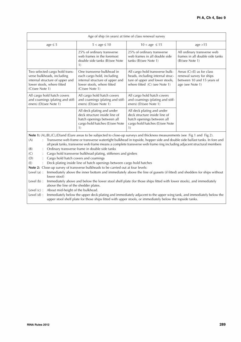
Pt A, Ch 4, Sec 9
RINA Rules 2012 289
25% of ordinary transverse web frames in the foremost double side tanks (B)(see Note 1)
25% of ordinary transverse web frames in all double side tanks (B)(see Note 1)
All ordinary transverse web frames in all double side tanks (B)(see Note 1)
Two selected cargo hold trans-verse bulkheads, including internal structure of upper and lower stools, where fitted (C)(see Note 1)
One transverse bulkhead in each cargo hold, including internal structure of upper and lower stools, where fitted (C)(see Note 1)
All cargo hold transverse bulk-heads, including internal struc-ture of upper and lower stools, where fitted (C) (see Note 1)
Areas (C)-(E) as for class renewal survey for ships between 10 and 15 years of age (see Note 1)
All cargo hold hatch covers and coamings (plating and stiff-eners) (D)(see Note 1)
All cargo hold hatch covers and coamings (plating and stiff-eners) (D)(see Note 1)
All cargo hold hatch covers and coamings (plating and stiff-eners) (D)(see Note 1)
All deck plating and under deck structure inside line of hatch openings between all cargo hold hatches (E)(see Note 1)
All deck plating and under deck structure inside line of hatch openings between all cargo hold hatches (E)(see Note 1)
Age of ship (in years) at time of class renewal survey
age ≤ 5 5 < age ≤ 10 10 < age ≤ 15 age >15
Note 1: (A),(B),(C),(D)and (E)are areas to be subjected to close-up surveys and thickness measurements (see Fig 1 and Fig 2).(A) : Transverse web frame or transverse watertight bulkhead in topside, hopper side and double side ballast tanks. In fore and
aft peak tanks, transverse web frame means a complete transverse web frame ring including adjacent structural members (B) : Ordinary transverse frame in double side tanks(C) : Cargo hold transverse bulkhead plating, stiffeners and girders(D) : Cargo hold hatch covers and coamings (E) : Deck plating inside line of hatch openings between cargo hold hatchesNote 2: Close-up survey of transverse bulkheads to be carried out at four levels:Level (a) : Immediately above the inner bottom and immediately above the line of gussets (if fitted) and shedders for ships without
lower stool)Level (b) : Immediately above and below the lower stool shelf plate (for those ships fitted with lower stools), and immediately
above the line of the shedder plates.Level (c) : About mid-height of the bulkhead.Level (d) : Immediately below the upper deck plating and immediately adjacent to the upper wing tank, and immediately below the
upper stool shelf plate for those ships fitted with upper stools, or immediately below the topside tanks.

Pt A, Ch 4, Sec 9
290 RINA Rules 2012
Figure 1 : Close-up Survey and Thickness Measurement Areas (1/1/2005)
Figure 2 : Ordinary transverse frame in double skin tank (1/1/2005)
4.2.2 (1/7/2006)All cargo holds, ballast tanks, including double bottom anddouble side tanks, pipe tunnels, cofferdams and void spacesbounding cargo holds, decks and outer hull are to be exam-ined, and this examination is to be supplemented by thick-ness measurement and testing as required in [4.5] and [4.6],to ensure that the structural integrity remains effective. Theaim of the examination is to discover substantial corrosion,significant deformation, fractures, damage or other struc-tural deterioration, that may be present.
4.2.3 (1/1/2005)All piping systems within the above spaces are to be exam-ined and operationally tested to working pressure to theattending Surveyor's satisfaction to ensure that tightness andcondition remain satisfactory.
4.2.4 (1/1/2005)The survey extent of ballast tanks converted to void spaceswill be specially considered by the Society in relation to therequirements for ballast tanks.
4.2.5 (1/7/2010)Where provided, the condition of the corrosion preventionsystem of ballast tanks is to be examined.
For ballast tanks, excluding double bottom tanks, where ahard protective coating is found in poor condition, and it isnot renewed, where a soft or semi-hard coating has been
D
A
A
EE
Typical transverse sectionAreas A and D C
A cargo hold, transverse bulkheadArea
Typical areas of deck plating and underdeck structure inside lineof hatch openings between cargo hold hatches
Area E
C
Upper stoolTopside tank
Hopper sidetank
Lower stool
Double bottom tank
Hatch opening
BArea

Pt A, Ch 4, Sec 9
RINA Rules 2012 291
applied, or where a hard protective coating has not beenapplied since the time of construction, the tanks in questionare to be examined at annual surveys. Thickness measure-ments are to be carried out as deemed necessary by the Sur-veyor.
When such a breakdown of hard protective coating is foundin water ballast double bottom tanks and it is not renewed,
where a soft or semi-hard coating is applied, or where ahard protective coating has not been applied since the timeof construction, the tanks in question may be examined atannual surveys. When considered necessary by the Sur-veyor, or where extensive corrosion exists, thickness meas-urements are to be carried out.
Table 3 : Minimum requirements for close-up survey at class renewal hull survey of ore carriers (1/7/2008)
Age of ship (in years) at time of class renewal survey
age ≤ 5 5 < age ≤ 10 10 < age ≤ 15 age >15
One web frame ring complete including adjacent structural members in a ballast wing tank. (A)(see Note 1)
All web frame rings complete including adjacent structural members in a ballast wing tank. (A)(see Note 1)
All web frame rings complete including adjacent structural members in each ballast tank. (A)(see Note 1)
All web frame rings complete including adjacent structural mem-bers in each ballast tank. (A)(see Note 1)
One transverse bulk-head lower part - including girder sys-tem and adjacent structural members - in a ballast tank. (A)(see Note 1)
One deck transverse including adjacent deck structural mem-bers in each remaining ballast tank. (A)(see Note 1)Forward and aft transverse bulk-heads complete - including girder system and adjacent struc-tural members - in a ballast wing tank. (A)(see Note 1)One transverse bulkhead lower part - including girder system and adjacent structural members - in each remaining ballast tank. (A)(see Note 1)
All transverse bulkheads complete - including girder system and adjacent structural members - in each ballast tank. (A)(see Note 1)One web frame ring complete including adjacent structural members in each wing void space. (A)(see Note 1)Additional web frame rings in void spaces as deemed necessary by the Society. (A)(see Note 1)
All transverse bulkheads complete - including girder system and adja-cent structural members - in each ballast tank. (A)(see Note 1)One web frame ring complete including adjacent structural mem-bers in each wing void space. (A)(see Note 1)Additional web frame rings in void spaces as deemed necessary by the Society. (A)(see Note 1)
Two selected cargo hold transverse bulk-heads, including inter-nal structure of upper and lower stools, where fitted. (C)(see Note 1)
One transverse bulkhead in each cargo hold, including internal structure of upper and lower stools, where fitted. (C)(see Note 1)
All cargo hold transverse bulk-heads, including internal struc-ture of upper and lower stools, where fitted. (C)(see Note 1)
All cargo hold transverse bulk-heads, including internal structure of upper and lower stools, where fitted. (C)(see Note 1)
Note 1:(A), (C), (D) and (E) are areas to be subjected to close-up surveys and thickness measurements according to Tab 4 (see Fig 3).(A) : Transverse web frame or transverse watertight bulkhead in topside, hopper side and double side ballast tanks. In fore
and aft peak tanks, transverse web frame means a complete transverse web frame ring including adjacent structural members
(C) : Cargo hold transverse bulkhead plating, stiffeners and girders(D) : Cargo hold hatch covers and coamings (E) : Deck plating and under deck structure inside line of hatch openings between cargo hold hatchesNote 2:Close-up Survey of transverse bulkheads to be carried out at four levels:Level (a) : Immediately above the inner bottom and immediately above the line of gussets (if fitted) and shedders for ships without
lower stool.Level (b) : Immediately above and below the lower stool shelf plate (for those ships fitted with lower stools), and immediately
above the line of the shedder plates.Level (c) : About mid-height of the bulkhead.Level (d) : Immediately below the upper deck plating and immediately adjacent to the upper wing tank, and immediately below
the upper stool shelf plate for those ships fitted with upper stools, or immediately below the topside tanks.

Pt A, Ch 4, Sec 9
292 RINA Rules 2012
Figure 3 : Close-up Survey and Thickness Measurement Areas of ore carriers (1/7/2009)
All cargo hold hatch covers and coamings (plating and stiffen-ers). (D)(see Note 1)
All cargo hold hatch covers and coamings (plating and stiffeners). (D)(see Note 1)
All cargo hold hatch covers and coamings (plating and stiffeners). (D)(see Note 1)
All cargo hold hatch covers and coamings (plating and stiffeners). (D)(see Note 1)
All deck plating and under deck structure inside line of hatch openings between all cargo hold hatches. (E)(see Note 1)
All deck plating and under deck structure inside line of hatch openings between all cargo hold hatches. (E)(see Note 1)
All deck plating and under deck structure inside line of hatch open-ings between all cargo hold hatches. (E)(see Note 1)
Age of ship (in years) at time of class renewal survey
age ≤ 5 5 < age ≤ 10 10 < age ≤ 15 age >15
Note 1:(A), (C), (D) and (E) are areas to be subjected to close-up surveys and thickness measurements according to Tab 4 (see Fig 3).(A) : Transverse web frame or transverse watertight bulkhead in topside, hopper side and double side ballast tanks. In fore
and aft peak tanks, transverse web frame means a complete transverse web frame ring including adjacent structural members
(C) : Cargo hold transverse bulkhead plating, stiffeners and girders(D) : Cargo hold hatch covers and coamings (E) : Deck plating and under deck structure inside line of hatch openings between cargo hold hatchesNote 2:Close-up Survey of transverse bulkheads to be carried out at four levels:Level (a) : Immediately above the inner bottom and immediately above the line of gussets (if fitted) and shedders for ships without
lower stool.Level (b) : Immediately above and below the lower stool shelf plate (for those ships fitted with lower stools), and immediately
above the line of the shedder plates.Level (c) : About mid-height of the bulkhead.Level (d) : Immediately below the upper deck plating and immediately adjacent to the upper wing tank, and immediately below
the upper stool shelf plate for those ships fitted with upper stools, or immediately below the topside tanks.
D
EE
Typical transverse sectionArea A C
Typical transverse bulkheadAreas A and
Typical areas of deck plating and underdeck structure inside lineof hatch openings between cargo hold hatches
Area E
Hatch opening
Area
Upper stool
Lower stool
Double bottomtank
A
C
A

Pt A, Ch 4, Sec 9
RINA Rules 2012 293
Table 4 : Minimum requirements to thickness measurements at class renewal hull survey of double skin bulk carriers (1/7/2008)
Table 5 : Requirements for extent of thickness measurements in those areas of substantial corrosion of double skin bulk carriers within the cargo length area (1/1/2005)
Age of ship (in years) at time of class renewal survey
age ≤ 5 5 < age ≤ 10 10 < age ≤ 15 age >15
Suspect areas Suspect areas Suspect areas Suspect areas
Within the cargo length:• Two transverse sections of deck
plating outside line of cargo hatch openings
Within the cargo length:• each deck plate outside line of
cargo hatch openings• two transverse sections, one in
the amidships area, outside line of cargo hatch openings
Within the cargo length:• each deck plate outside line of
cargo hatch openings• three transverse sections, one in
the amidships area, outside line of cargo hatch openings
• each bottom plate
Wind and water strakes in way of the two transverse sections considered above
All wind and water strakes within the cargo length area
All wind and water strakes, full length
Selected wind and water strakes out-side the cargo length area
Selected wind and water strakes out-side the cargo length area
Measurements, for general assess-ment and recording of corrosion pat-tern, of those structural members subject to close-up survey according to Tab 2
Measurements, for general assess-ment and recording of corrosion pat-tern, of those structural members subject to close-up survey according to Tab 2
Measurements, for general assess-ment and recording of corrosion pat-tern, of those structural members subject to close-up survey according to Tab 2
BOTTOM, INNER BOTTOM AND HOPPER STRUCTURE
Structural member Extent of measurement Pattern of measurement
Bottom, inner bottom and hopper structure plating
Minimum of three bays across double bottom tank, including aft bayMeasurements around and under all suction bell mouths
Five-point pattern for each panel between longitudinals and floors
Bottom, inner bottom and hopper structure longitudinals
Minimum of three longitudinals in each bay where bottom plating measured
Three measurements in line across flange and three measurements on the vertical web
Bottom girders, including watertight girders
At fore and aft watertight floors and in centre of tanks
Vertical line of single measurements on girder plating with one measurement between each panel stiffener, or a minimum of three meas-urements
Bottom floors, including watertight floors
Three floors in bays where bottom plating measured, with measurements at both ends and middle
Five-point pattern over two square metre area
Hopper structure web frame ring Three floors in bays where bottom plating measured
Five-point pattern over one square metre of plating Single measurements on flange
Hopper structure transverse water-tight bulkhead or swash bulkhead
• lower 1/3 of bulkhead • five-point pattern over one square metre of plating
• upper 2/3 of bulkhead • five-point pattern over two square metres of plating
• stiffeners (minimum of three) • For web, five-point pattern over span (two measurements across web at each end and one at centre of span). For flange, single measurements at each end and centre of span
Panel stiffening Where applicable Single measurements

Pt A, Ch 4, Sec 9
294 RINA Rules 2012
4.2.6 (1/7/2006)The class renewal survey is to include a bottom survey indry condition as laid down in Ch 3, Sec 6, [2.2.1].
The overall and close-up surveys and thickness measure-ments, as applicable, of the lower portions of the cargoholds and ballast tanks (see Note 1) are to be carried out inaccordance with the applicable requirements for classrenewal surveys, if not already performed.Note 1: Lower portions of the cargo holds and ballast tanks areconsidered to be the parts below the light ballast waterline.
4.2.7 (1/7/2006)Where a hard protective coating is provided in cargo holds,as defined in Sec 2, [1.1.7], and is found in good condition,the extent of close-up surveys and thickness measurementsmay be specially considered.
4.3 Hatch covers and coamings4.3.1 (1/1/2008)A thorough inspection of the items listed in [2.3] is to becarried out, in addition to all hatch covers and coamings.
4.3.2 (1/1/2005)A check of the satisfactory operation of all mechanicallyoperated hatch covers is to be made, including:
• stowage and securing in open condition;
• proper fit and efficiency of sealing in closed condition;
• operational testing of hydraulic and power components,wires, chains and link drives.
4.3.3 (1/1/2005)A check is to be made of the effectiveness of sealingarrangements of all hatch covers by hose testing or equiva-lent.
4.3.4 (1/1/2005)Thickness measurement of the hatch cover and coamingplating and stiffeners is to be carried out as given in Tab 4.
4.4 Overall and close-up surveys4.4.1 (1/7/2006)An overall survey of all cargo holds, tanks and spaces is tobe carried out at each class renewal survey. For fuel oil
tanks in the cargo length area, the requirements given inCh 3, Sec 5, Tab 5 are to be complied with.
4.4.2 (1/7/2008)The minimum requirements for close-up surveys at eachclass renewal survey are given in Tab 2 for double skin bulkcarriers, excluding ore carriers, and in Tab 3 for ore carriers.
4.4.3 (1/1/2005)The Surveyor may extend the close-up survey as deemednecessary taking into account the maintenance of thespaces under survey, the condition of the corrosion preven-tion system and where spaces have structural arrangementsor details which have suffered defects in similar spaces oron similar ships according to available information.
4.4.4 (1/1/2008)For areas in spaces where hard protective coatings arefound to be in a good condition, the extent of close-up sur-veys according to Tab 2 may be specially considered. Referalso to [4.2.7].
4.5 Thickness measurements4.5.1 (1/1/2005)The minimum requirements for thickness measurements atclass renewal surveys are given in Tab 4.
4.5.2 (1/7/2006)Provisions for extended measurements for areas with sub-stantial corrosion as defined in Ch 2, Sec 2, [2.2.7] aregiven in Tab 5 to Tab 8 and as may be additionally specifiedin the survey program as required in [4.1]. These extendedthickness measurements are to be carried out before thesurvey is credited as completed. Suspect areas identified atprevious surveys are to be examined. Areas of substantialcorrosion identified at previous surveys are to be subjectedto thickness measurements.
4.5.3 (1/7/2006)The Surveyor may further extend the thickness measure-ments as deemed necessary.
4.5.4 (1/7/2006)For areas in tanks where hard protective coatings are foundto be in a good condition, the extent of thickness measure-ments according to Tab 4 may be specially considered.Refer also to [4.2.7].

Pt A, Ch 4, Sec 9
RINA Rules 2012 295
Table 6 : Requirements for extent of thickness measurements in those areas of substantial corrosion of double skin bulk carriers within the cargo length area (1/1/2005)
DECK STRUCTURE INCLUDING CROSS STRIPS, MAIN CARGO HATCHWAYS, HATCH COVERS, COAMINGS AND TOPSIDE TANKS
Structural member Extent of measurement Pattern of measurement
Cross Deck Strip plating Suspect Cross Deck Strip plating Five-point pattern between underdeck stiff-eners over 1 metre length
Underdeck Stiffeners Transverse members
Longitudinal member
Five-point pattern at each end and mid spanFive-point pattern on both web and flange
Hatch Covers Side and end skirts, each three locations Three longitudinal bands, outboard strakes (2) and cen-treline strake (1)
Five-point pattern at each locationFive-point measurement each band
Mastre delle boccaporte Each side and end of coaming, one band lower 1/3, one band upper 2/3 of coaming
Five-point measurement each band i.e. end or side coaming
Topside Ballast Tanks Transverse watertight bulkheads:• Bulkhead
• Stiffeners
Five-point pattern over 1 sq. metre of plat-ingFive-point pattern over 1 metre length
Two representative transverse swash bulkheads:• Bulkhead
• Stiffeners
Five-point pattern over 1 sq. metre of plat-ingFive-point pattern over 1 metre length
Three representative bays of slope plating in all plating Five point pattern over 1 sq. metre of plat-ing
Longitudinals, suspect and adjacent Five point pattern over 1 sq. metre of plat-ing
Main Deck Plating Suspect plates and adjacent (4) Five-point pattern over 1 sq. metre of plat-ing
Main Deck Longitudinals Suspect Plates Five point pattern on both web and flange over 1 metre length
Web Frames/Transverses Suspect Plates Five-point pattern over 1 sq. metre

Pt A, Ch 4, Sec 9
296 RINA Rules 2012
Table 7 : Requirements for extent of thickness measurements in those areas of substantial corrosion of double skin bulk carriers within the cargo length area (1/7/2008)
Table 8 : Requirements for extent of thickness measurements in those areas of substantial corrosion of double skin bulk carriers within the cargo length area (1/1/2005)
4.5.5 (1/7/2006)
Transverse sections are to be chosen where the largestreductions are suspected to occur or are revealed from deckplating measurements.
4.5.6 (1/7/2006)
Representative thickness measurement to determine bothgeneral and local levels of corrosion in the transverse web
frames in all water ballast tanks is to be carried out. Thick-ness measurement is also to be carried out to determine thecorrosion levels on the transverse bulkhead plating. Theextent of thickness measurements may be specially consid-ered, provided the Surveyor is satisfied by the close-up sur-vey that there is no structural diminution and the hardprotective coating where applied remains efficient.
STRUCTURE IN DOUBLE SIDE SPACES OF DOUBLE SKIN BULK CARRIERS INCLUDING WING VOID SPACES OF ORE CARRIERS
Structural member Extent of measurement Pattern of measurement
Side shell and inner plating: Single measurement
• Upper strake and strakes in way of horizontal girders
• Plating between each pair of trans-verse frames/longitudinals in a mini-mum of three bays (along the tank)
• all other strakes • Plating between every third pair of longitudinals in same three bays
Side shell and inner side transverse frames /longitudinals on:
Three measurements across web and 1 measurement on flange
• upper strake • Each transverse frame/longitudinal in same three bays
• all other strakes • Every third transverse frame/longitudi-nal in same three bays
Transverse frames /longitudinals Minimum of three at top, middle and bot-tom of tank in same three bays
Five-point pattern over area of bracket
Vertical web and transverse bulkheads:
• strakes in a way of horizontal girders • Minimum of two webs and both trans-verse bulkheads
• Five-point pattern over approx. two square metre area
• other strakes • Minimum of two webs and both trans-verse bulkheads
• Two measurements between each pair of vertical stiffeners
Two measurements between each pair of vertical stiffeners
Plating on each girder in a minimum of three bays
Two measurements between each pair of longitudinal girder stiffeners
Panel stiffening Where applicable Single measurements
TRANSVERSE BULKHEADS IN CARGO HOLDS
Structural member Estensione delle misurazioni Distribuzione delle misurazioni
Lower stool, where fitted • Transverse band within 25mm of welded connection to inner bottom
• Transverse band within 25mm of welded connection to shelf plate
Five-point pattern between stiffen-ers over one metre length
Transverse bulkheads • Transverse band at approximately mid height • Transverse band at part of bulkhead adjacent to upper deck or
below upper stool shelf plate (for those ships fitted with upper stools)
Five-point pattern over one square metre of plating

Pt A, Ch 4, Sec 9
RINA Rules 2012 297
4.5.7 (1/7/2006)
When pitting is found on bottom plating and its intensity is20% or more, thickness measurements are to be extendedin order to determine the actual plate thickness out of thepits and the depth of the pits. Where the wastage is in thesubstantial corrosion range or the average depth of pitting is1/3 or more of the actual plate thickness, the pitted plate isto be considered as a substantially corroded area.
4.6 Tank testing
4.6.1 (1/7/2006)
All boundaries of water ballast tanks, deep tanks and cargoholds used for water ballast within the cargo length area areto be pressure tested. For fuel oil tanks, only representativetanks are to be pressure tested.
4.6.2 (1/1/2005)
The Surveyor may extend the tank testing as deemed neces-sary.
4.6.3 (1/7/2006)
Boundaries of ballast tanks are to be tested with a head ofliquid to the top of air pipes.
4.6.4 (1/7/2006)
Boundaries of ballast holds are to be tested with a head ofliquid to near the top of hatches.
4.6.5 (1/7/2006)
Boundaries of fuel oil tanks are to be tested with a head ofliquid to the highest point that liquid will rise to under serv-ice conditions. Tank testing of fuel oil tanks may be spe-cially considered based on a satisfactory externalexamination of the tank boundaries and confirmation fromthe Master stating that pressure testing has been carried outaccording to the requirements with satisfactory results.
4.6.6 (1/7/2006)
The testing of double bottom tanks and other spaces notdesigned for the carriage of liquid may be omitted, provideda satisfactory internal examination is carried out togetherwith an examination of the tank top.
4.7 Additional requirements after determin-ing compliance with SOLAS XII/12 (water level detectors) and XII/13 (availa-bility of pumping systems)
4.7.1 (1/1/2007)
For ships complying with the requirements of SOLAS XII/12for hold, ballast and dry space water level detectors, theclass renewal survey is to include an examination and a testof the water ingress detection systems and of their alarms.
4.7.2 (1/1/2007)
For ships complying with the requirements of SOLAS XII/13for the availability of pumping systems, the class renewal
survey is to include an examination and a test of the meansfor draining and pumping ballast tanks forward of the colli-sion bulkhead and bilges of dry spaces, any part of whichextends forward of the foremost cargo hold, and of theircontrols.
4.8 Survey Program
4.8.1 Basic information and particulars (1/1/2008)
Basic information and particulars of the ship are indicatedin Tab 9.
4.8.2 Scope (1/1/2008)
The present survey program covers the minimum extent ofoverall surveys, close-up surveys, thickness measurementsand pressure testing within the cargo length area, of cargoholds and ballast tanks, including fore and aft peak tanks,required by the Rules.
The arrangements and safety aspects of the survey are to beacceptable to the attending Surveyor(s).
4.8.3 Documentation (1/1/2008)
All documents used in the development of the survey pro-gram are to be available on board during the survey asrequired in [1.2].
4.8.4 Arrangement of tanks and spaces (1/1/2008)
This section of the survey program is to provide information(either in the form of plans or text) on the arrangement ofcargo holds, tanks and spaces that fall within the scope ofthe survey.
4.8.5 List of cargo holds, tanks and spaces with information on their use, extent of coatings and corrosion protection system (1/1/2008)
This section of the survey program is to indicate anychanges relating to (and is to update) the information on theuse of the holds and tanks of the ship, the extent of coatingsand the corrosion protective system provided in the SurveyPlanning Questionnaire referred to in [4.9].
4.8.6 Conditions for survey (1/1/2008)
This section of the survey program is to provide informationon the conditions for survey, e.g. information regardingcargo hold and tank cleaning, gas freeing, ventilation, light-ing etc.
4.8.7 Provisions and methods of access to structures (1/1/2008)
This section of the survey program is to indicate anychanges relating to (and is to update) the information on theprovisions and methods of access to structures provided inthe Survey Planning Questionnaire referred to in [4.9].

Pt A, Ch 4, Sec 9
298 RINA Rules 2012
Table 9 : Basic information and particulars (1/1/2008)
4.8.8 List of equipment for survey (1/1/2008)
This section of the survey program is to identify and list theequipment that will be made available for carrying out thesurvey and the required thickness measurements.
4.8.9 Survey requirements (1/1/2008)
a) Overall survey
This section of the survey program is to identify and listthe spaces that are to undergo an overall survey for theship in accordance with [4.3] and [4.4.1].
b) Close-up survey
This section of the survey program is to identify and listthe hull structures that are to undergo a close-up surveyfor the ship in accordance with [4.4.2].
4.8.10 Identification of tanks for tank testing (1/1/2008)
This section of the survey program is to identify and list thecargo holds and tanks that are to undergo tank testing forthe ship in accordance with [4.6].
4.8.11 Identification of areas and sections for thickness measurements (1/1/2008)
This section of the survey program is to identify and list theareas and sections where thickness measurements are to betaken in accordance with [4.3.4] and [4.5].
4.8.12 Minimum thickness of hull structures (1/1/2008)
This section of the survey program is to specify the mini-mum thickness for hull structures of the ship that are subjectto survey, according to (a) or (b):
a) determined from the attached wastage allowance tableand the original thickness according to the hull structureplans of the ship (see Note 1);
b) given in the following Tab 10:
Note 1: The wastage allowance tables are to be attached to the sur-vey program.
4.8.13 Thickness measurement company (1/1/2008)This section of the survey program is to identify changes, ifany, relating to the information on the thickness measure-ment company provided in the Survey Planning Question-naire referred to in [4.9].
4.8.14 Damage experience related to the ship (1/1/2008)
This section of the survey program, using Tab 11, shownbelow, is to provide details of the hull damage for at leastthe last three years in way of the cargo holds, ballast tanksand void spaces within the cargo length area. This damageis subject to survey.
4.8.15 Areas identified with substantial corrosion from previous surveys (1/1/2008)
This section of the survey program is to identify and list theareas of substantial corrosion from previous surveys.
Name of ship:
IMO number:
Flag State:
Port of registry:
Gross tonnage:
Deadweight (metric tonnes):
Length between perpendiculars (m):
Shipbuilder:
Hull number:
Classification Society:
Register Number:
Date of build:
Owner:
Thickness measurement company:
Any other information which may be useful

Pt A, Ch 4, Sec 9
RINA Rules 2012 299
Table 10 : As-built and minimum thickness for hull structures (1/1/2008)
Area or locationOriginal as-built thickness
(mm)Minimum thickness (mm)
Substantial corrosion thick-ness( mm)
Deck
Plating
Longitudinals
Longitudinal girders
Cross deck plating
Cross deck stiffeners
Bottom
Plating
Longitudinals
Longitudinal girders
Inner bottom
Plating
Longitudinals
Longitudinal girders
Floors
Ship side in way of topside tanks
Plating
Longitudinals
Ship side in way of hopper side tanks
Plating
Longitudinals
Ship side in way of double hull tanks
Plating
Longitudinals or ordinary transverse frames
Longitudinal stringers
Longitudinal bulkhead (inner side)
Plating
Longitudinals or ordinary transverse frames
Longitudinal girders
Transverse bulkheads
Plating
Stiffeners, if applicable
Upper stool plating
Upper stool stiffeners
Lower stool plating
Lower stool stiffeners
Transverse web frames in topside tanks
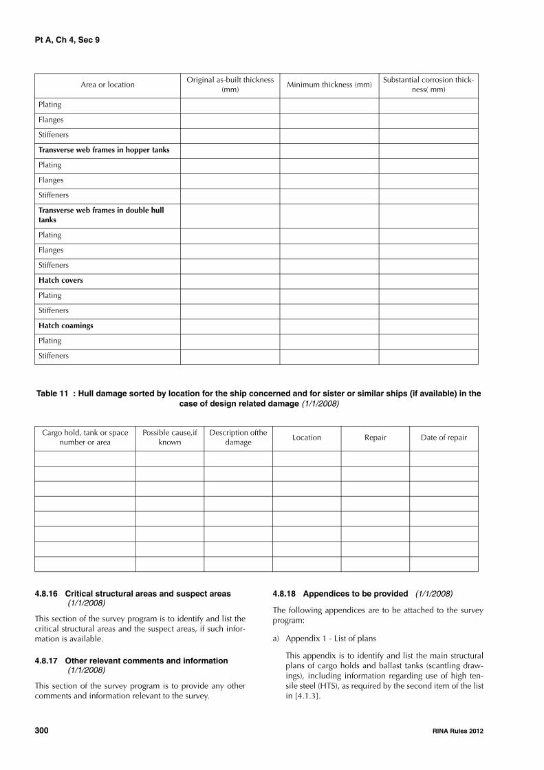
Pt A, Ch 4, Sec 9
300 RINA Rules 2012
Table 11 : Hull damage sorted by location for the ship concerned and for sister or similar ships (if available) in the case of design related damage (1/1/2008)
4.8.16 Critical structural areas and suspect areas (1/1/2008)
This section of the survey program is to identify and list thecritical structural areas and the suspect areas, if such infor-mation is available.
4.8.17 Other relevant comments and information (1/1/2008)
This section of the survey program is to provide any othercomments and information relevant to the survey.
4.8.18 Appendices to be provided (1/1/2008)
The following appendices are to be attached to the surveyprogram:
a) Appendix 1 - List of plans
This appendix is to identify and list the main structuralplans of cargo holds and ballast tanks (scantling draw-ings), including information regarding use of high ten-sile steel (HTS), as required by the second item of the listin [4.1.3].
Plating
Flanges
Stiffeners
Transverse web frames in hopper tanks
Plating
Flanges
Stiffeners
Transverse web frames in double hull tanks
Plating
Flanges
Stiffeners
Hatch covers
Plating
Stiffeners
Hatch coamings
Plating
Stiffeners
Cargo hold, tank or space number or area
Possible cause,if known
Description ofthe damage
Location Repair Date of repair
Area or locationOriginal as-built thickness
(mm)Minimum thickness (mm)
Substantial corrosion thick-ness( mm)

Pt A, Ch 4, Sec 9
RINA Rules 2012 301
b) Appendix 2 - Survey Planning Questionnaire
The Survey Planning Questionnaire (refer to [4.9]),which has been submitted by the Owner.
c) Appendix 3 - Other documentation
This part of the survey program is to identify and list anyother documentation that forms part of the plan.
4.8.19 Date and signature (1/1/2008)
The survey program is to be completed with the followingwording:
Prepared by the Owner in co-operation with the Society forcompliance with [4.1.3] of Pt A, Ch 4, Sec 9 of the Rules.
Date:…………………………………. (name and signature ofauthorised Owner's representative)
Date:…………………………………. (name and signature ofauthorised representative of the Society)
4.9 Survey Planning Questionnaire
4.9.1 General (1/1/2008)
The following information will enable the Owner in co-operation with the Society to develop a survey programcomplying with the requirements given in [4.8]. It is essen-tial that, when completing the present questionnaire, theOwner provides up-to-date information. The present ques-tionnaire, when completed, is to provide all informationand material required in [4.8].
4.9.2 Particulars (1/1/2008)
The particulars of the ship are indicated in Tab 12.
4.9.3 Information on access provision for close-up surveys and thickness measurement (1/1/2008)
The Owner is to indicate in Tab 13 the means of access tothe structures subject to close-up survey and thicknessmeasurement. A close-up survey is an examination wherethe details of structural components are within the close vis-
ual inspection range of the attending Surveyor, i.e. normallywithin reach of hand.
4.9.4 History of cargo (1/1/2008)
The Owner is to provide history of bulk cargoes of corrosivenature, e.g. with high sulphur content.
4.9.5 Owner's inspections (1/1/2008)
Using a format similar to that of Tab 14 (which is given asan example), the Owner is to provide details of the resultsof their inspections for the last three years on all cargo holdsand ballast tanks and void spaces within the cargo area,including peak tanks.
4.9.6 Reports of Port State Control inspections (1/1/2008)
The Owner is to provide a list of any reports of Port StateControl inspections containing hull structural related defi-ciencies and relevant information on rectification of thedeficiencies.
4.9.7 Safety Management System (1/1/2008)
The Owner is to provide a list of any non-conformitiesrelated to hull maintenance, including the associated cor-rective actions.
4.9.8 Approved thickness measurement company (1/1/2008)
The Owner is to provide the name and address of theapproved thickness measurement company.
4.9.9 Date and signature (1/1/2008)
The Survey Planning Questionnaire is to be completed withthe date, the name of the Owner's representative responsi-ble for filling in the document and his signature.
4.9.10 Availability of the form (1/1/2008)
An example of the "Survey Planning Questionnaire" form tobe filled in by the Owner is available on the Society websiteor may be supplied upon request; application may be madeto [email protected].
Table 12 : Particulars of the ship (1/1/2008)
Name of ship:
IMO number:
Flag State:
Port of registry:
Gross tonnage:
Deadweight (metric tonnes):
Classification Society:
Register Number:
Date of build:
Owner:
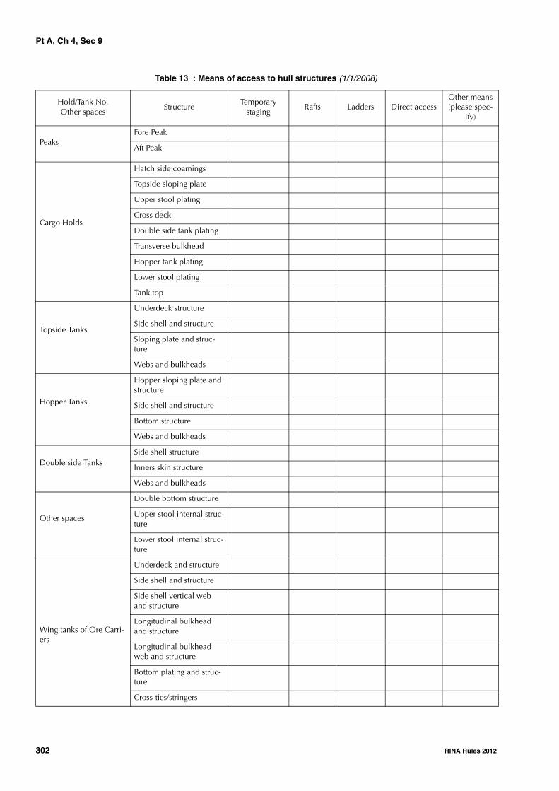
Pt A, Ch 4, Sec 9
302 RINA Rules 2012
Table 13 : Means of access to hull structures (1/1/2008)
Hold/Tank No.Other spaces
StructureTemporary
stagingRafts Ladders Direct access
Other means (please spec-
ify)
PeaksFore Peak
Aft Peak
Cargo Holds
Hatch side coamings
Topside sloping plate
Upper stool plating
Cross deck
Double side tank plating
Transverse bulkhead
Hopper tank plating
Lower stool plating
Tank top
Topside Tanks
Underdeck structure
Side shell and structure
Sloping plate and struc-ture
Webs and bulkheads
Hopper Tanks
Hopper sloping plate and structure
Side shell and structure
Bottom structure
Webs and bulkheads
Double side TanksSide shell structure
Inners skin structure
Webs and bulkheads
Other spaces
Double bottom structure
Upper stool internal struc-ture
Lower stool internal struc-ture
Wing tanks of Ore Carri-ers
Underdeck and structure
Side shell and structure
Side shell vertical web and structure
Longitudinal bulkhead and structure
Longitudinal bulkhead web and structure
Bottom plating and struc-ture
Cross-ties/stringers

Pt A, Ch 4, Sec 9
RINA Rules 2012 303
Table 14 : Owner's inspection report (1/1/2008)
Tank/Hold No.Other spaces
Corrosion protection (1)
Coating extent (2)Coating
condition (3)Structural
deterioration (4)Hold and tank
history (5)
Cargo holds
Topside tanks
Hopper tanks
Double side skin tanks
Double bottom tanks
Upper stools
Lower stools
Wing tanks (ore carriers)
Fore peak
Aft peak
Miscellaneous other spaces:
Note 1: Indicate tanks which are used for oil/ballast.(1) HC=hard coating; SC=soft coating; SH=semi-hard coating; NP=no protection(2) U=upper part; M=middle part; L=lower part; C=complete(3) G=good; F=fair; P=poor; RC=recoated (during the last three years)(4) N=no findings recorded; Y=findings recorded, description of findings is to be attached to the questionnaire(5) DR=damage and repair; L=leakages; CV= conversion (description is to be attached to this questionnaire)

Pt A, Ch 4, Sec 10
304 RINA Rules 2012
SECTION 10 OTHER SERVICE NOTATIONS
1 General
1.11.1.1 (1/7/2011)The requirements of this Section are applicable to ships tobe assigned one of the following service notations, andgiven in the Articles specified below:• container ship, or ship equipped for the carriage of
containers, in [2]• livestock carrier, in [3]• FLS tanker, in [4]• dredging units, i.e. ships with the service notations
dredger, hopper dredger, hopper unit, split hopperunit, split hopper dredger, in [5]
• tug, salvage tug, escort tug, in [6]• supply vessel, in [7]• fire-fighting ship, in [8]• oil recovery ship, in [9]• cable laying ship, in [10]• fishing vessel, in [11]• pipe laying ship, in [12]• research ship, in [13]• cement carrier, in [14]• asphalt tanker, in [15].
1.1.2 These requirements are additional to those given inChapter 3, according to the relevant surveys.
2 Container ship or ship equipped for the carriage of containers
2.1 Annual survey
2.1.1 The survey is to include:• confirmation of the availability of instructions and ins-
truments for stowage of containers, as required or fitted• examination of container supports welded to the ship’s
structure or on to the hatch covers• examination of cell guides, if fitted.
2.2 Class renewal survey
2.2.1 The renewal is to include:• examination of container supports welded to the ship’s
structure or on to the hatch covers, checking for possi-ble cracks and deformations
• examination of cell guides and associated elements,checking for possible cracks, deformations or corrosion.
2.2.2 For ships assigned with the service notation con-tainer ship, examination of the torsion box girder or equiva-
lent structure at the top sides is carried out. Thicknessmeasurements additional to those related to the transversesections may be required.
3 Livestock carrier
3.1 Annual survey3.1.1 (1/1/2007)The survey is to include a general examination of:• spaces for the livestock and related hatch covers (to be
surveyed according to Ch 3, Sec 3, [2])• ventilation means, including prime movers• main, emergency and portable lighting systems in live-
stock spaces, passageways and access routes• the drainage system• fodder and fresh water system.
3.2 Class renewal survey
3.2.1 The equipment related to ventilation, lighting andthe related power supply is to be submitted to a survey tothe same extent as required for similar equipment at theclass renewal survey as indicated in Ch 3, Sec 5.
3.2.2 The drainage, fodder and fresh water systems,including piping and pumps, are to be surveyed to the sameextent as required for similar equipment at the classrenewal survey as indicated in Ch 3, Sec 5.The fresh water tanks are to be internally examined inaccordance with the periodicity given in Ch 3, Sec 5, Tab 1.
4 FLS tanker
4.1 Annual survey - Hull items
4.1.1 Weather decksThe survey is to include:• examination of cargo tank openings, including gaskets,
covers, coamings and screens• examination of cargo tank pressure/vacuum valves and
flame screens• examination of flame screens on vents to all bunker, oily
ballast and oily slop tanks• examination of cargo, bunker, ballast and vent piping
systems, including remote control valves, safety valvesand various safety devices, as well as vent masts andheaders
• confirmation that wheelhouse doors and windows, side-scuttles and windows in superstructure and deckhouseends facing the cargo area are in satisfactory condition
• confirmation that pumps, valves and pipelines are iden-tified and distinctively marked.

Pt A, Ch 4, Sec 10
RINA Rules 2012 305
4.1.2 Cargo pump rooms and pipe tunnels
The survey is to include:
• examination of all pump room bulkheads and pipe tun-nels (if any) for signs of chemical cargo leakage or frac-tures and, in particular, the sealing arrangements ofpenetrations in pump room bulkheads
• examination of the condition of all piping systems, incargo pump rooms and pipe tunnels (if any)
• examination of the bilge and ballast arrangements andconfirmation that pumps and pipelines are identified.
4.2 Annual survey - Cargo machinery items
4.2.1 Cargo area and cargo pump rooms
The Owner or his representative is to declare to the attend-ing Surveyor that no modifications or alterations whichmight impair safety have been made to the various installa-tions in dangerous zones without prior approval from theSociety.
The survey is to include:
• confirmation that potential sources of ignition in or nearthe cargo pump rooms, such as loose gear, excessiveproduct in bilge, excessive vapours, combustible mate-rials, are eliminated and that access ladders are in satis-factory condition
• examination, as far as practicable, of cargo, bilge, bal-last and stripping pumps for excessive gland seal leak-age, verification of proper operation of electrical andmechanical remote operating and shutdown devicesand operation of pump room bilge system, and check-ing that pump foundations are intact
• confirmation that the ventilation system, including port-able equipment, if any, of all spaces in the cargo area(including cargo pump room) is operational, ducting isintact and screens are clean
• confirmation that electrical equipment in dangerouszones, cargo pump rooms and other spaces is in satis-factory condition and has been properly maintained
• confirmation that the remote operation of the cargopump room bilge system is satisfactory
• examination of the cargo heating system
• examination of the cargo-transfer arrangement and con-firmation that the ship's cargo hoses are suitable fortheir intended purpose and in satisfactory condition
• confirmation that any special arrangement made forbow or stern loading/unloading is in satisfactory condi-tion.
4.2.2 Instrumentation and safety devices
The survey is to include the following items, as far asrequired or fitted:
• examination of cargo tank gauging devices, high levelalarms and valves associated with overflow control
• confirmation that installed pressure gauges on cargo dis-charge lines are properly operational
• confirmation that the required gas detection instrumentsare on board and satisfactory arrangements have been
made for the supply of any required vapour detectiontubes
• confirmation that devices provided for measuring thetemperature of the cargo, if any, operate satisfactorily.
4.2.3 Inert gas systemIf an inert gas system such as that installed on board oiltankers is fitted, the requirements given in Sec 3, [3.3] are tobe complied with.
4.3 Intermediate survey - Hull items
4.3.1 The survey is to include:
• examination, as far as applicable, of cargo, stripping,cargo tank washing, bunker, ballast, steam and vent pip-ing systems as well as vent masts and headers. If uponexamination there is any doubt as to the condition ofthe piping, pressure testing, thickness measurement orboth may be required.
• confirmation that the pipelines are electrically bondedto the hull
• examination of vent line drainage arrangements.
4.4 Intermediate survey - Cargo machinery items
4.4.1 Electrical equipment in dangerous zonesA general examination of the electrical equipment andcables in dangerous zones such as cargo pump rooms andareas adjacent to cargo tanks is to be carried out for defec-tive and non-certified safe type electrical equipment, non-approved lighting and fixtures, and improperly installed ordefective or dead-end wiring.
The electrical insulation resistance of the electrical equip-ment and circuits terminating in or passing through the dan-gerous zones is to be tested; however, in cases where aproper record of testing is maintained, consideration maybe given to accepting recent test readings effected by theship’s personnel.
4.4.2 Cargo heating systemThe satisfactory condition of the cargo heating system is tobe verified.
4.4.3 Inert gas systemFor ships over 10 years old at the time of the intermediatesurvey due date, if an inert gas system such as that installedon board oil tankers is fitted, the requirements given inSec 3, [5.2] for intermediate survey of oil tankers are to becomplied with.
4.5 Class renewal survey - Hull items
4.5.1 PipingPiping for cargo, ballast, stripping and venting systems is tobe examined to the Surveyor's satisfaction. Dismantlingand/or thickness measurements of these items may berequired. A hydraulic test is to be carried out in the event ofrepair or dismantling of cargo or ballast piping, or wheredoubts arise.

Pt A, Ch 4, Sec 10
306 RINA Rules 2012
Vent line drainage arrangements are to be examined.
It is to be verified that cargo piping is electrically bonded tothe hull.
4.5.2 Safety valvesAll safety valves on cargo piping and of cargo tanks are tobe dismantled for examination, adjusted and, as applicable,resealed.
4.5.3 Cargo pump roomsAll cargo pump room boundaries are to be generally exam-ined. All gas-tight shaft sealing devices are to be examined.The bottom of cargo pump rooms is to be presented cleanfor the examination of stripping devices and gutters.
4.6 Class renewal survey - Cargo machinery items
4.6.1 PumpsBallast and stripping pumps are to be internally examinedand prime movers checked. A working test is to be carriedout.
Maintenance records of cargo pumps are to be made availa-ble to the Surveyor.
4.6.2 Washing systemWhere a washing system is fitted, piping, pumps, valves anddeck-mounted washing machines are to be examined andtested for signs of leakage, and anchoring devices of deck-mounted washing machines are to be checked to the Sur-veyor's satisfaction.
4.6.3 Cargo heating systemThe apparent satisfactory condition of the cargo heating sys-tem such as clamping, external condition of piping is to beverified and, if deemed necessary by the Surveyor, the sys-tem is to be pressure tested.
4.6.4 Remote controlsAn operating test of the emergency remote control of pumpsand valves and of automatic closing valves is to be carriedout.
4.6.5 Electrical equipment in dangerous zonesA general examination of the electrical equipment andcables in dangerous zones such as cargo pump rooms andareas adjacent to cargo tanks is to be carried out for defec-tive and non-certified safe type electrical equipment, non-approved lighting and fixtures, and improperly installed ordefective or dead-end wiring.
The electrical insulation resistance of the electrical equip-ment and circuits terminating in or passing through the dan-gerous zones is to be tested; however, in cases where aproper record of testing is maintained, consideration maybe given to accepting recent test readings effected by theship’s personnel.
4.6.6 Inert gas systemIf an inert gas system such as that installed on board oiltankers is fitted, the requirements given Sec 3, [5.2] forintermediate survey and in Sec 3, [7.2] for class renewalsurvey of oil tankers are to be complied with.
5 Dredging units
5.1 Annual survey
5.1.1 The survey is to include the following items, as far asrequired or fitted, according to the service notation of theship:
• for split hopper unit, split hopper dredger, visual exam-ination, as far as practicable, of superstructure hingesand blocks, deck hinges, hydraulic jacks and associatedpiping systems and alarms
• for dredger, hopper dredger, split hopper dredger:
- visual examination, as far as practicable, of attach-ments of suction piping and lifting systems to thestructure and external examination of piping indredging machinery spaces for absence of corrosionand leakage
- checking the condition of the dredging machineryspace and related equipment with regard to electri-cal shocks, protection from rotating machinery, fireand explosion hazards.
5.2 Class renewal survey
5.2.1 The survey is to include the following items, as far asrequired or fitted, according to the service notation of theship:
• for hopper dredger, hopper unit, visual examination ofhopper bottom doors or valves and accessories, such ashinges, actuating rods, hydraulic systems, with disman-tling as deemed necessary by the Surveyor
• for split hopper unit, split hopper dredger, visual exam-ination, as far as practicable, of superstructure hingesand blocks, deck hinges, hydraulic jacks and associatedpiping systems and alarms, with dismantling and/or fur-ther checks as deemed necessary by the Surveyor
• for dredger, hopper dredger, split hopper dredger:
- visual examination, as far as practicable, of attach-ments of suction piping and lifting systems to thestructure and external examination of piping indredging machinery spaces for absence of corrosionand leakage
- checking the condition of the dredging machineryspace and related equipment with regard to electri-cal shocks, protection from rotating machinery, fireand explosion hazards.
6 Tug, salvage tug, escort tug
6.1 Annual survey
6.1.1 The survey is to include a general external examina-tion of the towing hook or towing winch, as fitted, andunhooking device, as far as practicable.
6.1.2 In addition to [6.1.1] above, for salvage tug, theavailability and satisfactory condition of specific equipmentas required in Pt E, Ch 14, Sec 2, [3] is to be verified.

Pt A, Ch 4, Sec 10
RINA Rules 2012 307
6.1.3 For tug - barge combined, an examination of theaccessible parts of the connection system is to be carriedout.
6.2 Class renewal survey
6.2.1 The survey is to include:
• checking the condition of the connection of the towinghook or towing winch to the structure, including relatedreinforcements of the structure
• checking the external condition of the towing hook ortowing winch; when applicable, a no-load test of theunhooking device is to be carried out.
6.2.2 (1/7/2004)In addition to [6.2.1] above, for salvage tug, the survey is toinclude:
• a check and working test of specific equipment asrequired in Pt E, Ch 14, Sec 2, [3]
• checking of the satisfactory condition of the towingline(s).
6.2.3 For tug - barge combined, a visual examination ofcomponents of the connection system is to be carried out,completed by thickness measurements and non-destructivetests as deemed necessary by the Surveyor. A connec-tion/disconnection test is to be carried out, including acheck of related remote control, safety and alarm devices.
7 Supply vessel
7.1 Supply vessel - Oil product or Supply vessel - Chemical product
7.1.1 GeneralThe additional survey items for annual survey, intermediatesurvey and class renewal survey are applicable only to shipshaving the service notation supply vessel assigned the addi-tional service features oil product or chemical product.
7.1.2 Annual survey - Hull items
a) Weather decks
The survey is to include:
• examination of cargo tank openings, including gas-kets, covers, coamings and screens
• examination of cargo tank pressure/vacuum valvesand flame screens
• examination of flame screens on vents to all bunker,oily ballast and oily slop tanks
• examination of cargo, bunker, ballast and vent pip-ing systems, including remote control valves, safetyvalves and various safety devices, as well as ventmasts and headers
• confirmation that wheelhouse doors and windows,sidescuttles and windows in superstructure anddeckhouse ends facing the cargo area are in satisfac-tory condition
• confirmation that pumps, valves and pipelines areidentified and distinctively marked.
b) Cargo pump rooms and pipe tunnels
The survey is to include:
• examination of all pump room bulkheads and pipetunnels (if any) for signs of oil or chemical productleakage or fractures and, in particular, the sealingarrangements of penetrations in pump room bulk-heads
• examination of the condition of all piping systems,in cargo pump rooms and pipe tunnels (if any)
• examination of the bilge and ballast arrangementsand confirmation that pumps and pipelines are iden-tified.
7.1.3 Annual survey - Cargo machinery items (1/1/2007)
a) Cargo area and cargo pump rooms
The Owner or his representative is to declare to theattending Surveyor that no modifications or alterationswhich might impair safety have been made to the vari-ous installations in dangerous zones without priorapproval from the Society.
The survey is to include:
• confirmation that potential sources of ignition in ornear the cargo pump rooms, such as loose gear,excessive product in bilge, excessive vapours, com-bustible materials, etc., are eliminated and thataccess ladders are in satisfactory condition
• examination, as far as practicable, of cargo, bilge,ballast and stripping pumps for excessive gland sealleakage, verification of proper operation of electricaland mechanical remote operating and shutdowndevices and operation of pump room bilge system,and checking that pump foundations are intact
• confirmation that the ventilation system, includingportable equipment, if any, of all spaces in the cargoarea (including cargo pump rooms) is operational,ducting is intact and screens are clean
• confirmation that electrical equipment in dangerouszones, cargo pump rooms and other spaces is in sat-isfactory condition and has been properly main-tained
• confirmation that the remote operation of the cargopump room bilge system, if fitted, is satisfactory
• examination of the cargo heating system
• examination of the cargo-transfer arrangement andconfirmation that the ship's cargo hoses are suitablefor their intended purpose and in satisfactory condi-tion.
b) Instrumentation and safety devices
The survey is to include the following items, as far asrequired or fitted:
• examination of cargo tank gauging devices, highlevel alarms and valves associated with overflowcontrol
• confirmation that installed pressure gauges on cargodischarge lines are properly operational
• confirmation that the required gas detection instru-ments are on board and satisfactory arrangements

Pt A, Ch 4, Sec 10
308 RINA Rules 2012
have been made for the supply of any requiredvapour detection tubes
• confirmation that devices provided for measuringthe temperature of the cargo, if any, operate satisfac-torily.
7.1.4 Intermediate survey - Hull items
The survey is to include:
• examination, as far as applicable, of cargo, stripping,bunker, ballast, steam and vent piping systems as wellas vent masts and headers. If upon examination there isany doubt as to the condition of the piping, pressuretesting, thickness measurement or both may berequired.
• confirmation that the pipelines are electrically bondedto the hull
• examination of vent line drainage arrangements.
7.1.5 Intermediate survey - Cargo machinery items
a) Electrical equipment in dangerous zones
A general examination of the electrical equipment andcables in dangerous zones such as cargo pump roomsand areas adjacent to cargo tanks is to be carried out fordefective and non-certified safe type electrical equip-ment, non-approved lighting and fixtures, and improp-erly installed or defective or dead-end wiring.
The electrical insulation resistance of the electricalequipment and circuits terminating in or passingthrough the dangerous zones is to be tested; however, incases where a proper record of testing is maintained,consideration may be given to accepting recent testreadings effected by the ship’s personnel.
b) Cargo heating system
The satisfactory condition of the cargo heating system isto be verified.
7.1.6 Class renewal survey - Hull items
a) Piping
Piping for cargo, ballast, stripping and venting systemsis to be examined to the Surveyor's satisfaction. Dis-mantling and/or thickness measurements of these itemsmay be required. A hydraulic test is to be carried out inthe event of repair or dismantling of cargo or ballastpiping, or where doubts arise.
Vent line drainage arrangements are to be examined.
b) Safety valves
All safety valves on cargo piping and of cargo tanks areto be dismantled for examination, adjusted and, asapplicable, resealed.
c) Cargo pump rooms
All cargo pump room boundaries are to be generallyexamined. All gas-tight shaft sealing devices are to beexamined. The bottom of cargo pump rooms is to be
presented clean for the examination of strippingdevices and gutters.
7.1.7 Class renewal survey - Cargo machinery items
a) Pumps
Ballast and stripping pumps are to be internally exam-ined and prime movers checked. A working test is to becarried out.
Maintenance records of cargo pumps are to be madeavailable to the Surveyor.
b) Cargo heating system
The apparent satisfactory condition of the cargo heatingsystem such as clamping, external condition of piping isto be verified and, if deemed necessary by the Surveyor,the system is to be pressure tested.
c) Remote controls
An operating test of the emergency remote control ofpumps and valves and of automatic closing valves is tobe carried out.
d) Electrical equipment in dangerous zones
A general examination of the electrical equipment andcables in dangerous zones such as cargo pump roomsand areas adjacent to cargo tanks is to be carried out fordefective and non-certified safe type electrical equip-ment, non-approved lighting and fixtures, and improp-erly installed or defective or dead-end wiring.
The electrical insulation resistance of the electricalequipment and circuits terminating in or passingthrough the dangerous zones is to be tested; however, incases where a proper record of testing is maintained,consideration may be given to accepting recent testreadings effected by the ship’s personnel.
7.2 Supply vessel - Anchor handling or Sup-ply vessel - Anchor handling stab
7.2.1 General (1/7/2011)
The additional survey items for annual survey and classrenewal survey are applicable only to ships having the serv-ice notation supply vessel assigned the additional servicefeatures anchor handling or anchor handling stab.
7.2.2 Annual Survey (1/7/2011)
The survey is to include:
a) a general external examination of the anchor handlingwinch and foundations, as fitted
b) a function test of the winch, to the extent deemed nec-essary by the Surveyor.
The Manufacturer's recommendations are to be taken intoaccount.
7.2.3 Class renewal survey (1/7/2011)
In addition to the requirements in [7.2.2], a function test ofemergency release systems is to be carried out.

Pt A, Ch 4, Sec 10
RINA Rules 2012 309
8 Fire-fighting ship
8.1 Annual survey
8.1.1 Ship’s fire protectionThe survey is to include:
• general examination of arrangements for structural fireprotection
• ships equipped with a self-protection water-sprayingsystem: general examination of all parts, as far as practi-cable and visible, of self-protection water-spraying sys-tem, and of scuppers and freeing ports for waterdrainage from deck surfaces
• ships not equipped with a self-protection water-sprayingsystem: general examination of steel deadlights andshutters.
8.1.2 Water monitor systemThe survey is to include:
• general examination of all parts of the water monitorsystem (pumps, piping system, valves and other fittings)
• checking for proper operation of the system, includinglocal manual control
• general examination of foundations of water monitorsand check of local manual control.
8.1.3 Fixed and portable foam systemsThe survey is to include:
• general examination of the systems
• confirmation that the foam concentrates are periodicallytested, either by the Manufacturer or by an organisationagreed by him
• general examination of foundations of foam monitorsand check of local manual control
• for fixed foam systems, reference is to be made to Ch 3,Sec 3, [3.4.2] e).
8.1.4 Machinery installations, control room and other devices
The survey is to include:
• general examination of spaces containing auxiliarymachinery for fire-fighting systems, particular attentionbeing paid to arrangements, piping systems and instru-ments; check of tools and of pressure vessels and theirfittings, if any
• general examination of the control station and check ofall communication and remote control means, of venti-lation system
• general examination of sea suctions of fire-fighting sys-tems, of relevant remote and local control and of pipingsystems, including the relevant protection against corro-sion
• general external examination of electrical installationsfor fire-fighting systems, with particular regard to thealarms and searchlights,
• checking of other fire-fighting arrangements
• checking of firemen’s outfits, confirmation that they arestored in the appropriate locations, and checking of aircompressor and other equipment.
8.2 Class renewal survey
8.2.1 The survey is to include:
• complete test of water fire-extinguishing systems,including the internal examination, as required by theSurveyor, of the relevant pumps
• partial test, at the Surveyor's discretion, of fixed foamfire-extinguishing systems
• test of self-protection fixed water-spraying systems,putting into operation the spray nozzles, including theinternal examination, as required by the Surveyor, of therelevant pumps
• examination and test of prime movers of machinery rel-evant to fire-fighting systems and of the air compressorfor refilling of air bottles of breathing apparatuses
• examination and test of the electrical generating plantsupplying power to fire-fighting systems and search-lights
• test of searchlights.
9 Oil recovery ship
9.1 Annual survey
9.1.1 (1/1/2007)
The survey is to include:
• confirmation of the availability of the operating manual
• examination of cargo tank openings, including gaskets,covers, coamings and screens
• general examination of cargo, ballast and vent pipingsystems, including control, gauging, alarm and safetydevices
• general examination of the cargo pump room, asregards ventilation systems, condition of pumps andpiping systems, and signs of any oil leakage
• confirmation that electrical equipment in dangerousareas, cargo pump rooms and other spaces, if fitted, is insatisfactory condition; the Owner or his representative isto declare to the attending Surveyor that this equipmenthas been properly maintained
• confirmation of the availability and satisfactory condi-tion of the fixed cargo gas detection system, includingrelated alarms, portable gas detection equipment, andoil flash point measurement equipment.
If any inert gas system is fitted, the requirements for theannual survey of such installations given in Sec 3, [3.3] areapplicable.
9.2 Class renewal survey
9.2.1 Piping
Cargo, ballast, stripping and vent piping is to be examinedto the Surveyor's satisfaction. Dismantling and/or thicknessmeasurements may be required. Tightness or working testsare to be carried out. A hydraulic or hydropneumatic test isto be carried out in the event of repair or dismantling ofcargo or ballast piping, or where doubts arise.

Pt A, Ch 4, Sec 10
310 RINA Rules 2012
Vent line drainage arrangements are to be examined.
It is to be verified that cargo piping is electrically bonded tothe hull.
9.2.2 Safety valves
Safety valves on cargo piping and of cargo tanks are to bedismantled for examination, adjusted and, as applicable,resealed.
9.2.3 Pumps
Ballast and stripping pumps are to be internally examinedand prime movers checked. A working test is to be carriedout.
Maintenance records of cargo pumps are to be made availa-ble to the Surveyor.
9.2.4 Cargo pump rooms
Cargo pump room boundaries are to be generally exam-ined. Gas-tight shaft sealing devices are to be examined.The bottom of cargo pump rooms is to be presented cleanfor the examination of stripping devices and gutters.
9.2.5 Electrical equipment in dangerous zones
A general examination of the electrical equipment andcables in dangerous zones such as cargo pump rooms andareas adjacent to cargo tanks is to be carried out for defec-tive and non-certified safe type electrical equipment, non-approved lighting and fixtures, and improperly installed ordefective or dead-end wiring.
An insulation test of circuits is to be carried out; however,where a proper record of testing is maintained, considera-tion may be given to accepting recent readings effected bythe ship’s personnel.
9.2.6 Instrumentation and safety devices
The fixed cargo gas detection system, including relatedalarms, portable gas detection equipment, and oil flash-point measurement equipment, is to be tested.
9.2.7 Inert gas system
If any inert gas system is fitted, the requirements for theclass renewal survey of such installations given in Sec 3,[7.2] are applicable.
10 Cable laying ship
10.1 Annual survey
10.1.1 (1/1/2007)
The survey is to include a general examination of sheaves,drums and tensioners for damage, cracks or wastage. Theconnections of these appliances to the structure are also tobe checked.
10.2 Class renewal survey
10.2.1 The equipment mentioned in [10.1.1] is to be dis-mantled, to the extent deemed necessary by the Surveyor, inorder to check its condition. Clearances of sheaves andcable drum axles are to be ascertained.
11 Fishing vessel
11.1 Annual survey
11.1.1 The survey is to include:• general examination of areas subject to damage, corro-
sion or wastage, such as the stern ramp, weather deck inway of the working area of the nets, connections to hullstructure of masts, gantries, winches and traw gallows(for side trawlers)
• general examination of the measures for the protectionof the crew against falling overboard, such as stormrails, means of protection near stern ramp, etc.
11.2 Class renewal survey
11.2.1 For fishing vessels of 10 years age and over, theclass renewal survey is to include thickness measurementsof structural elements prone to rapid wastage, such as thestern ramp, weather deck in way of the working area of thenets, connections to hull structure of masts, gantries,winches and traw gallows (for side trawlers).
12 Pipe laying ship
12.1 Annual survey12.1.1 (1/1/2005)The survey is to include:• general examination of the pipe laying and anchoring
equipment for damage, cracks or wastage; the connec-tions of these appliances to the structure are also to bechecked
• general examination of areas subject to damage, cracksor wastage of the weather deck in way of the workingarea and pipe storage area.
The annual survey of dynamic positioning equipment is tobe carried out in accordance with the requirements of Ch 5,Sec 11, [5.1].
12.2 Class renewal survey12.2.1 (1/1/2005)The equipment mentioned in [12.1.1] is to be dismantled,to the extent deemed necessary by the Surveyor, in order tocheck its condition. Tests are to be carried out to verify theproper operation of all machinery and equipment intendedfor pipe laying and anchoring equipment.
The renewal survey of dynamic positioning equipment is tobe carried out in accordance with the requirements of Ch 5,Sec 11, [5.2].
13 Research ship
13.1 Annual and Class renewal survey13.1.1 (1/1/2005)The survey is to include the examination, to the extentdeemed necessary by the Surveyor, of the equipment andarrangements on the basis of which the service notation hasbeen assigned.

Pt A, Ch 4, Sec 10
RINA Rules 2012 311
14 Cement carrier
14.1 Annual survey14.1.1 (1/2/2005)The survey is to include the general examination of thecement handling system for damage, cracks or wastage; theconnections of the system to the hull structure are also to bechecked.
14.2 Class renewal survey14.2.1 (1/2/2005)The cement handling system is to be dismantled, to theextent deemed necessary by the Surveyor, in order to checkits condition; the connections of the system to the hullstructure are also to be checked. Tests are to be carried outto verify the proper operation of machinery and equipmentintended for the cement handling system.
15 Asphalt tanker
15.1 Annual survey - Hull items
15.1.1 Weather decks (1/7/2011)The survey is to include:
a) examination of cargo tank openings, including gaskets,covers, coamings and screens
b) examination of cargo tank pressure/vacuum valves andflame screens
c) examination of flame screens on vents to all bunkertanks
d) examination of cargo, bunker, ballast and vent pipingsystems, including remote control valves, safety valvesand various safety devices
e) confirmation that wheelhouse doors and windows, side-scuttles and windows in superstructure and deckhouseends facing the cargo area are in satisfactory condition
f) confirmation that pumps, valves and pipelines are iden-tified and distinctively marked.
15.1.2 Cargo pump rooms and pipe tunnels (1/7/2011)
The survey is to include:
a) examination of all pump room bulkheads and pipe tun-nels (if any) for signs of cargo leakage or fractures and,in particular, the sealing arrangements of penetrations inpump room bulkheads
b) examination of the condition of all piping systems, incargo pump rooms and pipe tunnels (if any)
c) examination of the bilge and ballast arrangements andconfirmation that pumps and pipelines are identified.
15.1.3 Independent cargo tanks (1/7/2011)The survey is to include, as far as practicable, the generalexternal examination of the structure surrounding the inde-pendent cargo tanks for damage, cracks or wastage, includ-ing the thermal isolating material and elements supportingand/or securing the cargo tanks.
15.2 Annual survey - Cargo machinery items
15.2.1 Cargo area and cargo pump rooms (1/7/2011)The survey is to include:
a) confirmation that potential sources of ignition in or nearthe cargo pump rooms, such as loose gear, excessiveproduct in bilge, excessive vapours, combustible mate-rials, are eliminated and that access ladders are in satis-factory condition
b) examination, as far as practicable, of cargo, bilge, bal-last and stripping pumps for excessive gland seal leak-age, verification of proper operation of electrical andmechanical remote operating and shutdown devicesand operation of the pump room bilge system, andchecking that pump foundations are intact
c) confirmation that the ventilation system, including port-able equipment, if any, of all spaces in the cargo area(including cargo pump room) is operational, ducting isintact and screens are clean
d) confirmation that electrical equipment in cargo pumprooms and other spaces is in satisfactory condition andhas been properly maintained
e) confirmation that the remote operation of the cargopump room bilge system is satisfactory
f) examination of the cargo heating system
g) examination of the cargo-transfer arrangement and con-firmation that any hoses are suitable for their intendedpurpose and, where appropriate, type approved ormarked with the date of testing.
15.2.2 Instrumentation and safety devices (1/7/2011)The survey is to include the following items, as far asrequired or fitted:
a) examination of cargo tank gauging devices
b) confirmation that installed pressure gauges on cargo dis-charge lines are properly operational
c) confirmation that devices provided for measuring thetemperature of the cargo, if any, operate satisfactorily.
15.3 Intermediate survey - Hull items15.3.1 (1/7/2011)The survey is to include:
a) examination of weather decks,
b) examination, as far as applicable, of cargo, stripping,bunker, ballast, steam and vent piping systems. If uponexamination there is any doubt as to the condition ofthe piping, pressure testing, thickness measurement orboth may be required.
15.4 Class renewal survey - Hull items
15.4.1 Piping (1/7/2011)Piping for cargo, ballast, stripping and venting systems is tobe examined to the Surveyor's satisfaction. Dismantlingand/or thickness measurements of these items may berequired. A hydraulic test is to be carried out in the event ofrepair or dismantling of cargo or ballast piping, or wheredoubts arise.

Pt A, Ch 4, Sec 10
312 RINA Rules 2012
15.4.2 Safety valves (1/7/2011)All safety valves on cargo piping and of cargo tanks are tobe dismantled for examination, adjusted and, as applicable,resealed.
15.4.3 Cargo pump rooms (1/7/2011)All cargo pump room boundaries are to be generally exam-ined. All gas-tight shaft sealing devices are to be examined.The bottom of cargo pump rooms is to be presented cleanfor the examination of stripping devices and gutters.
15.4.4 Independent cargo tanks (1/7/2011)The survey is to include the internal examination of theindependent cargo tanks and external examination of thestructure surrounding the independent cargo tanks for dam-age, cracks or wastage, including the thermal isolatingmaterial and elements supporting and/or securing the cargotanks.
15.5 Class renewal survey - Cargo machinery items
15.5.1 Pumps (1/7/2011)
Ballast and stripping pumps are to be internally examinedand prime movers checked. A working test is to be carriedout.
Maintenance records of cargo pumps are to be made availa-ble to the Surveyor.
15.5.2 Cargo heating system (1/7/2011)
The apparent satisfactory condition of the cargo heating sys-tem such as clamping and piping is to be verified and, ifdeemed necessary by the Surveyor, the system is to be pres-sure tested.

Pt A, Ch 4, App 1
RINA Rules 2012 313
APPENDIX 1 SURVEY REPORTING PRINCIPLES FOR SHIPS
SUBJECT TO ENHANCED SURVEY PROGRAM
1 Survey reporting principles
1.1 General
1.1.1 (1/7/2006)
As a principle, for ships subject to the requirements ofSec 2, Sec 3, Sec 4, Sec 5 and Sec 9, the report for surveysof hull structure and piping systems, as relevant for the sur-vey, is to include the content indicated in this Appendix.
1.2 Issue of a survey report
1.2.1 (1/7/2006)
A survey report is to be issued in the following cases:
a) In connection with commencement, continuation and /or completion of periodical hull surveys, i.e. annual,intermediate and class renewal surveys, as relevant
b) When structural damage / defects have been found
c) When repairs, renewals or modifications have been car-ried out
d) When condition of class (recommendation) has beenimposed or deleted.
1.3 Purpose of reporting
1.3.1 (1/7/2006)
The purpose of reporting is to provide:
a) Evidence that prescribed surveys have been carried outin accordance with applicable classification Rules
b) Documentation of surveys carried out with findings,repairs carried out and recommendations imposed ordeleted
c) Survey records, including actions taken, which are toform an auditable documentary trail. Survey reports areto be kept in the survey report file required to be onboard
d) Information for planning of future surveys
e) Information which may be used as input for mainte-nance of classification Rules and instructions.
1.4 Surveys split between different stations
1.4.1 (1/7/2006)
When a survey is split between different survey stations, areport is to be made for each portion of the survey. A list ofitems surveyed, relevant findings and an indication ofwhether the item has been credited are to be made availa-ble to the next attending Surveyor, prior to continuing orcompleting the survey. Thickness measurement and tank
testing carried out are also to be listed for the use of the nextSurveyors.
1.5 Identification of spaces and areas
1.5.1 (1/7/2006)
The following spaces, locations, structures and systems, asapplicable, are to be identified:
a) the compartments where an overall survey has beencarried out;
b) the locations, in each ballast tank and cargo holdincluding hatch covers and coamings, where a close-upsurvey has been carried out, together with informationof the means of access used (see Note 1);
c) the locations, in each ballast tank and cargo holdincluding hatch covers and coamings, where thicknessmeasurements have been carried out (see Note 1);
Note 1: As a minimum, the identification of locations of close-upsurvey and thickness measurements is to include a descriptionof individual structural members corresponding to the extent ofrequirements stipulated in the pertinent Section of this Chapterbased on the type of periodical survey and the ship's age.Where only partial survey is required owing to the ship's age,the identification is to include the location within each ballasttank or cargo hold by reference to frame numbers.
d) the structures subject to special consideration for thoseareas in ballast tanks or cargo holds where protectivecoating is found to be in good condition and the extentof close-up survey and / or thickness measurement hasbeen specially considered;
e) the tanks subjected to tank testing;
f) the piping systems on deck, including cargo and crudeoil washing (COW) piping and cargo and ballast pipingwithin cargo and ballast tanks and/or holds, as applica-ble, pipe tunnels, cofferdams and void spaces where:
1) examination including internal examination of pip-ing with valves and fittings and thickness measure-ment, as relevant, has been carried out;
2) an operational test to working pressure has beencarried out.
1.6 Items surveyed
1.6.1 (1/7/2006)
The following items of the survey are to be reported:
a) type, extent and condition of protective coating in eachtank, as relevant (rated good, fair or poor);

Pt A, Ch 4, App 1
314 RINA Rules 2012
b) structural condition of each compartment with informa-tion on the identified findings, as relevant, such as:
1) corrosion with description of location, type andextent
2) areas with substantial corrosion
3) cracks / fractures with description of location andextent
4) buckling with description of location and extent
5) indents with description of location and extent
c) compartments where no structural damage / defectshave been found
The report may be supplemented by sketches and/or photos.
1.7 Thickness measurement report1.7.1 (1/7/2006)The thickness measurement report is to be verified andsigned by the Surveyor controlling the measurements onboard.
1.8 Longitudinal strength1.8.1 (1/7/2006)For oil tankers of both single and double hull constructionof 130 m in length and upwards and over 10 years of age,for which the longitudinal strength of the hull girder is to beevaluated, the following data is to be included, as relevant:
a) measured and as-built transverse sectional areas of deckand bottom flanges
b) diminution of transverse sectional areas of deck andbottom flanges
c) details of renewals or reinforcements carried out, as rel-evant (as per [1.10.1]).
1.9 List of required repairs1.9.1 (1/7/2006)Whenever the attending Surveyor is of the opinion thatrepairs are required, each item to be repaired is to be identi-fied in a numbered list.
1.10 List of repairs carried out1.10.1 (1/1/2008)Whenever repairs are carried out, details of the repairseffected are to be reported by making specific reference tothe relevant items in the numbered list. Repairs carried outare to be reported with identification of:
a) compartment
b) structural member
c) repair method (i.e. renewal or modification) including:
• steel grades and scantlings (if different from the orig-inal),
• sketches/photos, as appropriate,
d) repair extent
e) NDT / Tests.
1.11 List of repairs not completed1.11.1 (1/7/2006)For repairs not completed at the time of survey, a recom-mendation is to be imposed with a specific time limit for therepairs. In order to provide correct and proper informationto the Surveyor attending for survey of the repairs, the rec-ommendation is to be sufficiently detailed with identifica-tion of each item to be repaired. For identification ofextensive repairs, reference may be made to the surveyreport.

RINA Rules 2012 315
Part AClassification and Surveys
Chapter 5
SCOPE OF SURVEYS RELATED TO ADDITIONALCLASS NOTATIONS
SECTION 1 GENERAL
SECTION 2 STAR (SYSTEM OF TRACE AND ANALYSIS OF RECORDS)
SECTION 3 AVAILABILITY OF MACHINERY
SECTION 4 AUTOMATED MACHINERY SYSTEMS
SECTION 5 INTEGRATED SHIP SYSTEMS
SECTION 6 MONITORING EQUIPMENT
SECTION 7 POLLUTION PREVENTION
SECTION 8 REFRIGERATING INSTALLATIONS
SECTION 9 ARRANGEMENTS FOR NAVIGATION IN ICE - ICE CLASS AND POLAR CLASS
SECTION 10 WINTERISATION (TEMP)
SECTION 11 OTHER NOTATIONS

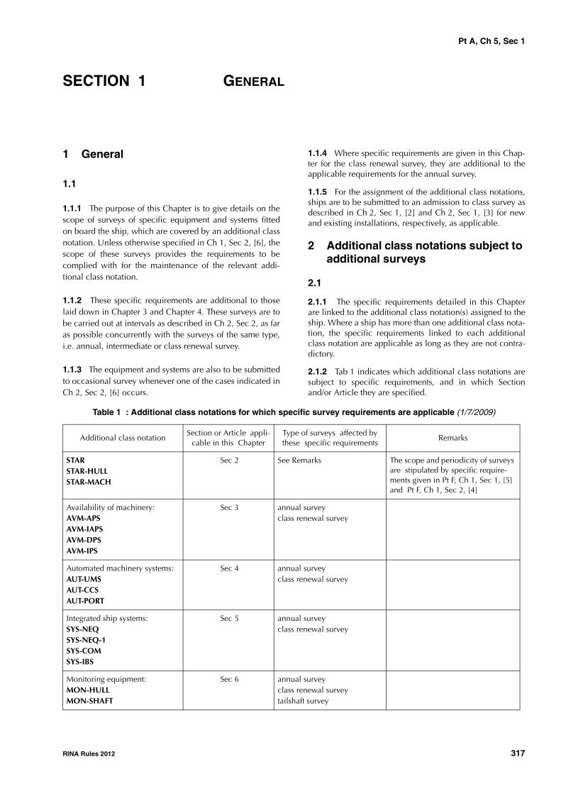
Pt A, Ch 5, Sec 1
RINA Rules 2012 317
SECTION 1 GENERAL
1 General
1.1
1.1.1 The purpose of this Chapter is to give details on thescope of surveys of specific equipment and systems fittedon board the ship, which are covered by an additional classnotation. Unless otherwise specified in Ch 1, Sec 2, [6], thescope of these surveys provides the requirements to becomplied with for the maintenance of the relevant addi-tional class notation.
1.1.2 These specific requirements are additional to thoselaid down in Chapter 3 and Chapter 4. These surveys are tobe carried out at intervals as described in Ch 2, Sec 2, as faras possible concurrently with the surveys of the same type,i.e. annual, intermediate or class renewal survey.
1.1.3 The equipment and systems are also to be submittedto occasional survey whenever one of the cases indicated inCh 2, Sec 2, [6] occurs.
1.1.4 Where specific requirements are given in this Chap-ter for the class renewal survey, they are additional to theapplicable requirements for the annual survey.
1.1.5 For the assignment of the additional class notations,ships are to be submitted to an admission to class survey asdescribed in Ch 2, Sec 1, [2] and Ch 2, Sec 1, [3] for newand existing installations, respectively, as applicable.
2 Additional class notations subject to additional surveys
2.1
2.1.1 The specific requirements detailed in this Chapterare linked to the additional class notation(s) assigned to theship. Where a ship has more than one additional class nota-tion, the specific requirements linked to each additionalclass notation are applicable as long as they are not contra-dictory.
2.1.2 Tab 1 indicates which additional class notations aresubject to specific requirements, and in which Sectionand/or Article they are specified.
Table 1 : Additional class notations for which specific survey requirements are applicable (1/7/2009)
Additional class notationSection or Article appli-
cable in this ChapterType of surveys affected by these specific requirements
Remarks
STARSTAR-HULLSTAR-MACH
Sec 2 See Remarks The scope and periodicity of surveys are stipulated by specific require-ments given in Pt F, Ch 1, Sec 1, [5] and Pt F, Ch 1, Sec 2, [4]
Availability of machinery:AVM-APSAVM-IAPSAVM-DPSAVM-IPS
Sec 3 annual surveyclass renewal survey
Automated machinery systems:AUT-UMSAUT-CCSAUT-PORT
Sec 4 annual surveyclass renewal survey
Integrated ship systems:SYS-NEQSYS-NEQ-1SYS-COMSYS-IBS
Sec 5 annual surveyclass renewal survey
Monitoring equipment:MON-HULLMON-SHAFT
Sec 6 annual surveyclass renewal surveytailshaft survey

Pt A, Ch 5, Sec 1
318 RINA Rules 2012
Pollution preventionCLEAN-SEACLEAN-AIRGREEN PLUSGREEN STAR 3GREEN STAR 3 DESIGNLOWSOx (N)
Sec 7 annual surveyclass renewal survey
Refrigerating installationsREF-CARGOREF-CONTREF-STORE
Sec 8 annual surveyclass renewal survey
Navigation in ice environmentICE CLASS IA SUPERICE CLASS IAICE CLASS IBICE CLASS ICICE CLASS IDICEPOLAR CLASS
Sec 9 class renewal survey
PMSPMS-CM(PROP)PMS-CM(HVAC)PMS-CM(CARGO)PMS-CM(ELE)PMS-CM(FDS)
See Remarks See Remarks The scope and periodicity of surveys are stipulated by specific require-ments given in Part F, Chapter 12
WINTERIZATION Sec 10 annual survey
Other notationsSTRENGTHBOTTOMGRABLOADING - GRAB [X]SPMDYNAPOSVCSCOVENTCARGOCONTROLCOAT-WBTDIVINGSUPPORTHVSCFIRE
Sec 11 As applicable in accordance with the related Articles in Sec 11
Additional class notationSection or Article appli-
cable in this ChapterType of surveys affected by these specific requirements
Remarks

Pt A, Ch 5, Sec 2
RINA Rules 2012 319
SECTION 2 STAR (SYSTEM OF TRACE AND ANALYSIS OF
RECORDS)
1 General
1.1 Application1.1.1 (1/7/2009)The requirements of this Section apply to ships which havebeen assigned one of the following additional class nota-tions related to the STAR system, as described in Ch 1,Sec 2, [6.2]:
STAR
STAR-HULL
STAR-MACH
1.1.2 When the STAR notation is assigned, the surveyrequirements stipulated for both STAR-HULL and STAR-MACH are to be complied with.
2 STAR-HULL
2.1 Survey scope and periodicity
2.1.1 The scope and periodicity of surveys for the mainte-nance of the STAR-HULL notation are given in Pt F, Ch 1,Sec 1, [5].
3 STAR-MACH
3.1 Survey scope and periodicity
3.1.1 (1/7/2009)
The scope and periodicity of surveys for the maintenance ofthe STAR-MACH notation are given in Pt F, Ch 1, Sec 2, [4].

Pt A, Ch 5, Sec 3
320 RINA Rules 2012
SECTION 3 AVAILABILITY OF MACHINERY
1 General
1.1
1.1.1 (1/7/2008)
The requirements of this Section apply to ships which havebeen assigned one of the following additional class nota-tions related to availability of machinery, as described inCh 1, Sec 2, [6.3] :
AVM-APS or AVM-APS-NS
AVM-IAPS
AVM-DPS or AVM-DPS-NS
AVM-IPS.
2 Annual survey
2.1
2.1.1 At each annual survey the Owner or his representa-tive is to declare to the attending Surveyor that no modifica-tions have been made to the systems affecting the notationswithout prior approval by the Society.
3 Class renewal survey
3.1
3.1.1 At each class renewal survey a test is to be con-ducted in order to ascertain that the systems affecting thenotations operate satisfactorily. This test is usually to be car-ried out during sea trials.

Pt A, Ch 5, Sec 4
RINA Rules 2012 321
SECTION 4 AUTOMATED MACHINERY SYSTEMS
1 General
1.11.1.1 (1/7/2009)The requirements of this Section apply to ships which havebeen assigned one of the following additional class nota-tions related to automated machinery systems, as describedin Ch 1, Sec 2, [6.4]:
AUT-UMS
AUT-CCS
AUT-PORT
2 Annual survey
2.1
2.1.1 The Owner or his representative is to declare to theattending Surveyor that no significant modifications havebeen made without prior approval by the Society.
2.1.2 The annual survey is to include:• an examination of the engineers’ log-book to verify the
proper operation of automation systems in the periodsubsequent to the last survey and measures taken toavoid repetition of any malfunctions or failures whichhave occurred during the same period
• a general examination of the control systems covered bythe notation, including a random check of the properoperation and calibration of main measuring, monitor-ing, alarm, and automatic shut-off devices
• a check of the fire detectors
• a check of the bilge flooding alarms
• a running test which may be also performed by a spotcheck method.
3 Class renewal survey
3.1
3.1.1 The requirements given in [2] for annual survey areto be complied with. An additional program of examina-tions, checks and tests is to be devised in agreement withthe Owner and based on the operational data and experi-ence of previous surveys. This program is to include verifi-cation of the calibration of instruments and testing ofcontrol and safety functions of the machinery. The Owner isto produce evidence that all these checks and tests havebeen carried out and this will be verified by the Surveyor atrandom. In addition, the proper operation of the controlsystem of propulsion machinery is to be checked during seatrials.

Pt A, Ch 5, Sec 5
322 RINA Rules 2012
SECTION 5 INTEGRATED SHIP SYSTEMS
1 General
1.1
1.1.1 (1/1/2007)The requirements of this Section apply to ships which havebeen assigned one of the following additional class nota-tions related to integrated ship systems, as described inCh 1, Sec 2, [6.5]:
SYS-NEQ
SYS-NEQ-1
SYS-COM
SYS-IBS
2 Annual survey
2.1 All notations
2.1.1 The Owner or his representative is to declare to theattending Surveyor that no significant modifications havebeen made to the relevant installations without the priorapproval by the Society.
An examination of the log-books is to be carried out to ver-ify the proper operation of systems in the period subsequentto the last survey and measures taken to avoid repetition ofany malfunctions or failures which have occurred duringthe same period
2.2 Notations SYS-NEQ and SYS-NEQ-1
2.2.1 The annual survey is to include:
a) general:
• general examination of the bridge layout, withregard to the field of vision, window wipe and washsystem, wheelhouse lighting and heating/coolingsystems, and arrangements for the safety of naviga-tors
b) propulsion and steering controls:
• test of the steering gear to confirm the proper opera-tion of the various remote controls from the wheel-house
• test, as far as practicable, of the propulsion control,including propeller pitch control, where fitted
• check of the relevant indicators such as rudderangle, ahead/astern position, propeller rpm or pitch
c) navigation aids:
• test of the satisfactory operating condition of radars
• test of the functions available at quay side of theARPA and collision avoidance system
• test of the position fixing system
• test of the gyro compass system
• test of the echo sounding device, using appropriatescale of depth
• test of other available alarms (sounding equipment,self-checking device, etc.), as far as practicable
d) communications:
• test of the whistle control device from the relevantworkstation
• check of the different communication systems (inter-nal communication, VHF radiotelephone installa-tion, NAVTEX)
e) bridge safety and alarm system (notation SYS-NEQ-1)
• test, as far as practicable, of the vigilance system andrelated alarm/warning transfer system.
2.3 Notation SYS-COM
2.3.1 The annual survey is to include a check of the meansof transmission (hardware and software) as follows :
a) compliance of the environmental conditions of use ofthe components (such as temperature, power supply)with those for which they were approved
b) verification of the correct installation on board, includ-ing hardware (cabling, location of aerial, layout of con-sole) and software (such as compatibility of assembledsoftware, man machine interface)
c) verification by means of an appropriate test of theproper function of:
• the internal communication between the differentworkstations, checking at random the availability ofdata
• the external communication with the shore; consid-eration may be given to recent records of such exter-nal communication from ship to shore and fromshore to ship
2.4 Notation SYS-IBS
2.4.1 The annual survey is to include a check of the condi-tion of the different workstations that belong to the IBS sys-tem, and a test, as far as practicable, of:
• the main functions of the IBS; in this respect, the exami-nations and tests given in [2.2.1] are to be carried out,where applicable
• the transitional and emergency sources required for thesystem and recovery of systems after restoring power
• the alarm and monitoring system in the wheelhouse, atrandom.

Pt A, Ch 5, Sec 5
RINA Rules 2012 323
3 Class renewal survey
3.1 All notations
3.1.1 The requirements given in [2] for annual survey areto be complied with. An additional program of examina-tions, checks and tests is to be devised in agreement withthe Owner and based on the operational data and experi-
ence of previous surveys. This program is to include verifi-cation of the calibration of instruments and testing ofcontrol and safety functions of the installation. An addi-tional program of random tests of the systems is to be per-formed during sea trials.
The Owner is to confirm that any modification to the hard-ware and software is fully documented and properlyrecorded.

Pt A, Ch 5, Sec 6
324 RINA Rules 2012
SECTION 6 MONITORING EQUIPMENT
1 General
1.1 Application
1.1.1 The requirements of this Section apply to shipswhich have been assigned one of the following additionalclass notations related to hull and tailshaft monitoringequipment, as described in Ch 1, Sec 2, [6.6]:MON-HULL
MON-SHAFT
2 MON-HULL
2.1 Annual and class renewal survey
2.1.1 The Owner or his representative is to declare to theattending Surveyor that the hull monitoring equipment hasbeen recently calibrated using a reference loading case.
3 MON-SHAFT
3.1 Tailshaft survey
3.1.1 When the records of the tailshaft bearing tempera-ture readings are checked and doubts arise, the Surveyormay require the verification of the accuracy of the gaugingdevices.

Pt A, Ch 5, Sec 7
RINA Rules 2012 325
SECTION 7 POLLUTION PREVENTION
1 General
1.1 Application1.1.1 (22/10/2008)The requirements of this Section apply to ships which havebeen assigned one of the following additional class nota-tions related to pollution prevention systems, as describedin Ch 1, Sec 2, [6.8]:
CLEAN-SEA
CLEAN-AIR
GREEN PLUS
GREEN STAR 3
GREEN STAR 3 DESIGN
LOW SOx (N)
1.1.2 (1/7/2006)When the GREEN STAR 3 DESIGN notation is assigned, thesurvey requirements of [2] and [3] are to be complied with.
2 CLEAN-SEA
2.1 Annual and class renewal survey2.1.1 (1/7/2010)The survey is, as far as applicable, to include:
a) Certificates and documents• confirmation that the IOPP certificate is valid• confirmation that the "International Pollution Pre-
vention Certificate for the Carriage of Noxious Liq-uid Substances in Bulk" or the "InternationalCertificate of Fitness for the Carriage of DangerousChemicals in Bulk" (ICOF CHE Certificate), as appli-cable, is valid
• confirmation that the "International Sewage Pollu-tion Prevention Certificate" (ISPP Certificate) is valid
• confirmation that the "International Anti Fouling Sys-tem Certificate" (AFS Certificate) or statement ofcompliance is valid
• confirmation that an approved SOPE Plann or SMPEPlan, as applicable, is available on board
• verification of the proper updating of the sewagerecord book
• confirmation that an approved Ballast Water Man-agement Plan is available on board and verificationof the proper updating of the ballast water recordbook
• confirmation that an approved Garbage Manage-ment Plan is available on board and verification ofthe proper updating of the garbage record book
• confirmation that the Ship Environmental Manage-ment Plan is available on board
• verification that an officer, defined as Ship Environ-mental Manager, is in service on board
• confirmation that the special list or manifest or adetailed stowage plan related to the harmful sub-stances carried is available on board
b) for oily wastes• check of the compliance of the bilge system with the
approved drawings (no bypasses for overboard dis-charge)
• verification that a periodical calibration of the bilgewater filtering equipment has been carried out whenrequired by the Manufacturer's instructions or, in theabsence of specific indications, at least every 6months and that documents reporting the last cali-bration are available on board
• verification that the Oil Systems log-book is dulyfilled in (at least every week)
• verification that the overflow system and high levelalarm, or overflow system and flow alarm in theoverflow main, or two high level alarms (90% and95%), installed on fuel oil and lubricating oil tankswith volume >10m3 are well maintained and ingood working condition
• verification that each fixed container or encloseddeck area provided with fuel or lubricating oil tankvents, overflows and fill pipe connection on theweather and/or superstructure decks is well main-tained and in good working condition
c) for sewage• confirmation of the proper operation of the sewage
treatment plant• verification of the satisfactory condition of the stand-
ard sewage discharge connection• verification that high level alarms for sewage hold-
ing tanks are well maintained and in good workingcondition
d) for grey water (only for passenger ships)• verification that the grey water record book is duly
filled in (grey water discharge into the sea is to beperformed at a distance of more than 4 nauticalmiles from the nearest land)
• verification that high level alarms for grey waterholding tanks are well maintained and in goodworking condition
e) for garbage• verification of the effective application of the Ship
Environmental Management Plan• verification of proper location of placards for gar-
bage dischange• confirmation of the proper operation of the garbage
treatment plant fitted on board

Pt A, Ch 5, Sec 7
326 RINA Rules 2012
• verification that the garbage record book is properlyfilled in
• only for passenger ships other than ro-ro passenger,verification that the total quantity of wastes landedfor recycling (Wr) is over the minimum limit fixed byCLEAN SEA regulation and of corrective actionsundertaken if the minimum limit has not beenreached
f) for harmful aquatic organisms in ballast water• examination of the ballast water treatment system,
where fitted, based on the Manufacturer's mainte-nance instructions
g) for harmful substances carried in packaged form• verification, to the Surveyor's satisfaction, that the
harmful substances are properly stowed as specifiedin the above documentation
h) for ship recycling• verification that the Green Passport is available on
board and verification, to the Surveyor's satisfaction,of proper updating, where the ship has undergonemodification work affecting the Green Passport.
3 CLEAN-AIR
3.1 Annual and class renewal survey3.1.1 (1/7/2004)The survey is, as far as applicable, to include:
a) Certificates and documents• confirmation that the Ship Environmental Manage-
ment Plan is available on board.• confirmation that the "Engine International Air Pollu-
tion Prevention Certificates " (EIAPP Certificate orDocument of Compliance) are available on board asapplicable
• confirmation that the engine technical file andrecord book are available on board and properlyupdated
• verification that the VCS notation is still granted tothe ship (this item applies to ships classed with oneor more of the following service notations: oil tanker- chemical tanker - FLS tanker - liquefied gas carrier- combination carrier OOC - combination carrierOBO)
• verification of the records kept on board of the pur-chase orders and sulphur content check of the fueland of the management of fuels when fuels with dif-ferent sulphur contents are used
• confirmation that the Manufacturer's operating man-uals for incinerators are available on board
b) for emissions of ozone depleting substances• verification of the availability of the operating man-
ual detailing the procedures to be followed to mini-mise the risk of releasing ozone depletingsubstances in all the operative and emergency con-ditions
• verification of the annual consumption figures ofrefrigerants and of corrective actions undertaken ifthe 10% limit has been exceeded
c) for emissions of nitrogen oxides (NOx)• verification of the proper operation of the devices to
control NOx emissions• verification that engine parameters are as specified
in the engine technical file• verification of replacements of engine components
with those specified in the engine technical file
d) for emissions of sulphur exhaust (SOx)
• examination of the exhaust gas cleaning system,where fitted, based on the Manufacturer's mainte-nance instructions
e) for emissions from incinerators• examination of the incinerators in working condi-
tions, including monitoring and control devices.
4 GREEN PLUS
4.1 Annual and class renewal survey4.1.1 (1/7/2009)The survey is, as far as practicable, to include the checksrequired in [2] and [3] and, in addition, the following:
a) verification that the marine growth prevention systemsare well maintained and in good working condition;
b) verification required by [2.1.1] d) for all ships;
c) verification that all the additional systems and compo-nents involved in the ship's environmental index calcu-lation (see Pt F, Ch 7, Sec 1, Tab 2 and Pt F, Ch 7, Sec 1,[7], if any) are well maintained and in good workingcondition;
d) verification that all the additional procedural meansinvolved in the ship's environmental index calculation(see Pt F, Ch 7, Sec 1, Tab 2 and Pt F, Ch 7, Sec 1, [7], ifany) are followed and documented by appropriaterecording;
e) verification that adequate training on environmentalissues is planned, carried out and documented for allthe persons on board having influence on the environ-mental behaviour of the ship.
5 GREEN STAR 3
5.1 Annual and class renewal survey5.1.1 (1/7/2010)The survey is, as far as applicable, to include:
a) Certificates and documents
• confirmation that the IOPP certificate is valid• confirmation that the "International Pollution Pre-
vention Certificate for the Carriage of Noxious Liq-uid Substances in Bulk" or the "InternationalCertificate of Fitness for the Carriage of DangerousChemicals in Bulk" (ICOF CHE Certificate), as appli-cable, is valid
• confirmation that the "International Sewage Pollu-tion Prevention Certificate" (ISPP Certificate) is valid
• confirmation that the "International Anti Fouling Sys-tem Certificate" (AFS Certificate) or statement of

Pt A, Ch 5, Sec 7
RINA Rules 2012 327
compliance is valid (Antifouling systems applied onexisting ships and not in compliance with IMO Res./MEPC.102(48) are to be removed or sealed the nexttime the ship is in dry dock).
• confirmation that the "Engine International Air Pollu-tion Prevention Certificates" (EIAPP Certificate orDocument of Compliance) are available on board asapplicable
• confirmation that the engine technical file andrecord book are available on board and properlyupdated
• confirmation that an approved SOPE Plan or SMPEPlan, as applicable, is available on board and thatthe ship is enrolled in RINA's Emergency ResponseService
• verification that the VCS notation is still granted tothe ship (this item applies to ships classed with oneor more of the following service notations: oil tanker- chemical tanker - FLS tanker - liquefied gas carrier- combination carrier OOC - combination carrierOBO)
• verification of the records kept on board of the pur-chase orders and sulphur content check of the fueland of the management of fuels when fuels with dif-ferent sulphur contents are used
• confirmation that the Manufacturer's operating man-uals for incinerators are available on board
• verification of the proper updating of the sewagerecord book
• confirmation that an approved Ballast Water Man-agement Plan is available on board and verificationof the proper updating of the ballast water recordbook
• confirmation that an approved Garbage Manage-ment Plan is available on board and verification ofthe proper updating of the garbage record book
• confirmation that the Ship Environmental Manage-ment Plan is available on board.
• verification that an officer, defined as EnvironmentalShip Manager, is in service on board.
• confirmation that the special list or manifest ordetailed stowage plan related to the harmful sub-stances carried is available on board
b) for oily wastes• check of the compliance of the bilge system with the
approved drawings (no bypasses for overboard dis-charge)
• verification that a periodical calibration of the bilgewater filtering equipment has been carried out whenrequired by the Manufacturer's instructions or, in theabsence of specific indications, at least every 6months and that documents reporting the last cali-bration are available on board
• verification that the emergency equipment for acci-dental spillage of oil, listed in the SOPE Plan, is onboard and in good condition and that the crew isconfident with such equipment
• verification that the Oil Systems log book is dulyfilled in (at least every week)
• verification that the overflow system and high levelalarm, or overflow system and flow alarm in theoverflow main, or two high level alarms (90% and95%), installed on fuel oil and lubricating oil tankswith volume >10m3 are well maintained and ingood working condition
• verification that each fixed container or encloseddeck area provided with fuel or lubricating oil tankvents, overflows and fill pipe connection on theweather and/or superstructure decks is well main-tained and in good working condition
c) for sewage
• confirmation of the proper operation of the sewagetreatment plant
• verification of the satisfactory condition of the stand-ard sewage discharge connection
• verification that high level alarms of sewage holdingtanks are well maintained and in good working con-dition
d) for grey water (only for passenger ships)
• verification that the grey water record book is dulyfilled in (grey water discharge into the sea is to beperformed at a distance of more than 4 nauticalmiles from the nearest land)
• ·verification that high level alarms for grey waterholding tanks are well maintained and in goodworking condition
e) for garbage
• verification of the effective application of the ShipEnvironmental Management Plan
• verification of proper location of placards for gar-bage discharge
• confirmation of the proper operation of the garbagetreatment plant fitted on board
• only for passenger ships other than ro-ro passenger,verification that the total quantity of wastes landedfor recycling (Wr) is over the minimum limit fixed byGREEN STAR 3 regulation and of corrective actionsundertaken if the minimum limit has not beenreached
f) for harmful aquatic organisms in ballast water
• examination of the ballast water treatment system,where fitted, based on the Manufacturer's mainte-nance instructions
g) for harmful substances carried in packaged form
• verification, to the Surveyor's satisfaction, that theharmful substances are properly stowed as specifiedin the above documentation
h) for emissions of ozone depleting substances
• verification of the availability of the operating man-ual detailing the procedures to be followed to mini-mise the risk of releasing ozone depletingsubstances in all the operative and emergency con-ditions
• verification of the annual consumption figures ofrefrigerants and of corrective actions undertaken ifthe allowable limit has been exceeded

Pt A, Ch 5, Sec 7
328 RINA Rules 2012
i) for emissions of nitrogen oxides (NOx)• verification of the proper operation of the devices to
control NOx emissions• verification that engine parameters are as specified
in the engine technical file• verification of replacements of engine components
with those specified in the engine technical file• examination of the incinerators in working condi-
tions, including monitoring and control devices
j) for emissions of sulphur exhaust (SOx)• examination of the exhaust gas cleaning system,
where fitted, based on the Manufacturer's mainte-nance instructions.
6 LOW SOx (N)
6.1 Annual and class renewal survey
6.1.1 (1/7/2006)
The survey is to include:
• confirmation that the IAPP certificate is valid
• confirmation that detailed plans of systems and equip-ment to limit SOx emission in the SOx emission controlareas are available on board
• confirmation that the Ship SOx Environmental Manage-ment Plan is available on board.

Pt A, Ch 5, Sec 8
RINA Rules 2012 329
SECTION 8 REFRIGERATING INSTALLATIONS
1 General
1.1
1.1.1 The requirements of this Section apply to shipswhich have been assigned one of the following additionalclass notations related to refrigerating installations, asdescribed in Ch 1, Sec 2, [6.9]:
REF-CARGO
REF-CONT
REF-STORE
as well as the following specific notations:
-PRECOOLING
-QUICKFREEZE
-AIRCONT.
2 Annual survey
2.1 General
2.1.1 The annual survey of refrigerating installations(plants and spaces) is to be carried out with the installationin running condition and, whenever possible, duringunloading operations or without cargo in refrigeratedspaces.
2.1.2 The refrigeration installation log-book (or other simi-lar record) is to be made available to the Surveyor for exam-ination of the records since the last survey, and checkingany unusual consumption of refrigerant, breakdown ordefective items.
2.1.3 Decks, bulkheads or ship sides adjacent to refriger-ated spaces are to be checked as far as practicable in orderto verify the absence of cold spots.
2.1.4 The Owner or his representative is to declare to theattending Surveyor that no significant modifications havebeen made to the installations that could affect the classnotations without the prior approval by the Society.
2.2 Refrigerating plant
2.2.1 Refrigerating machines and related accessories,including compressors, condensers, pumps and piping areto be examined externally and in running condition. Insula-
tion of insulated parts is to be checked for possible signs ofhumidity or wear. The tightness of the system is to be ascer-tained.
2.2.2 The electrical installation is to be generally exam-ined, and the insulation resistance of the installation is to bechecked as deemed necessary by the Surveyor.
2.2.3 If independent from the electrical installation of theship, the generators supplying electrical power to the refrig-erating installation are to be examined to the same extent asdescribed in Ch 3, Sec 3, [3.3].
2.3 Refrigerated spaces
2.3.1 Refrigerated spaces are to be generally examined toascertain the condition of:
• insulation lining; removable panels or covers may bedismantled for examination of insulation, as deemednecessary by the Surveyor
• hatch covers, doors, access panels (including gasketsand securing devices) and dampers of ventilation ducts
• air coils, coolers, fans, air ducts, brine piping systemsand associated equipment; cleanliness of grids
• bilge wells
• protection of fans and other rotating machinery, battensfor air circulation within the space.
2.4 Instrumentation and safety devices
2.4.1 Thermometers used for measurement of temperaturein refrigerated spaces, air ducts and other elements of theinstallation are to be examined and checked for their accu-racy. The Surveyor may require the calibration of one ormore thermometers and one or more automation devices tobe checked in his presence or, failing this, a certificate ofcalibration is to be presented to him.
2.4.2 The following alarm and safety devices are also to bechecked, as required or fitted:
• alarm and emergency shutdown devices
• CO2 detectors, if any
• refrigerant leakage detectors
• access to spaces, with regard to possibilities of escapeand prevention of personnel being trapped withinspaces.

Pt A, Ch 5, Sec 8
330 RINA Rules 2012
2.5 Notation -AIRCONT
2.5.1 The requirements of this item apply to installationsassigned the notation -AIRCONT. They are additional to therequirements given in [2.1] to [2.4].
2.5.2 The installation is to be visually examined and testedto verify that the controlled atmosphere system remains sat-isfactory. The survey is to include the following items:
• examination of voyage logs, records of controlledatmosphere zone air-tightness and calibration of instru-ments
• confirmation that an operating and safety manual isavailable on board, complete and duly endorsed by theofficers responsible
• examination of controlled atmosphere zone sealingarrangements including cleats and hinges, pressure/vac-uum valves, door locks, ventilation of adjacent spaces,warning notices
• test to design pressure of controlled atmosphere zonesfor air-tightness. Tests by ship's staff within one monthprior to the survey may be accepted, based on a writtenreport by the Master subject to visual inspection con-firming the air-tightness.
• operation and performance test of the gas supply equip-ment, including controls, alarms, interlocks and safetydevices
• examination and test of ventilation arrangementsincluding fans as deemed necessary
• examination of electrical supply arrangements
• check of gas analysers, analysing equipment and cali-bration
• check of relative humidity sensors and calibration
• check of permanent and portable gas monitoring, inclu-ding calibration, and of personnel safety equipment.
3 Class renewal survey
3.1 General
3.1.1 The installation is to be surveyed out of operation inorder to enable examinations in opened condition of cer-tain items.
3.1.2 After completion of these examinations, the installa-tion is to be checked while cooling down from the ambienttemperature to the lowest design temperature for the refrig-erated spaces. The plant is to be examined for ability tomaintain stable air temperatures and defrosting operation isto be checked.
3.2 Refrigerating plant
3.2.1 The equipment is to be dismantled to a sufficientextent to enable the following examinations:
• reciprocating compressors: examination of cylinders,valves, crankshaft, connecting rods, pistons, bearingsand safety devices
• screw compressors, turbo compressors and pumps:parts subject to wear and tear; the equipment may notneed to be opened up if log-book records and a runningtest show proper functioning.
3.2.2 Prime movers of pumps, compressors and fans are tobe examined to the same extent as required in Ch 3, Sec 5,[3] for similar equipment for the class renewal survey ofmachinery.
3.2.3 Condensers and coolers are to be opened up forexamination of tube plates, tubes and end covers.
Condensers are to be pressure tested to 1,2 times the ratedworking pressure.
3.2.4 Insulation of insulated parts (such as piping and pres-sure vessels) may need to be removed at random, to ascer-tain the condition of such parts and of the insulation itself.
3.2.5 The electrical installation of the plant is to be exam-ined and insulation tests checked.
3.2.6 If independent from the electrical installation of theship, the generators supplying electrical power to the refrig-erating installation are to be examined to the same extent asdescribed in Ch 3, Sec 5, [3.6].
3.2.7 Sea connections to condenser circulating pumps areto be opened up and piping examined.
3.2.8 Other equipment, such as oil separators on refriger-ant systems, filters and dehydrators, are to be examined tothe satisfaction of the Surveyor.
3.3 Refrigerated spaces
3.3.1 The lining and insulation in the refrigerated spacesmay need to be partly removed for examination of its condi-tion. The condition of the hull part under the insulation isthen ascertained, as well as that of girders, meat rails, hooksand coil/cooler supports.
3.3.2 Air coolers and coils are to be examined and pres-sure tested at the rated working pressure and at 1,2 timessuch pressure in the case of hydraulic test after repairs.
3.3.3 Air cooler fans are to be examined and their primemovers are to be checked to the same extent as stated in[3.2.2].
3.3.4 The electrical installation in the refrigerated spaces isto be examined and insulation tests checked.
3.3.5 Defrosting and heating systems are to be examinedto the satisfaction of the Surveyor.

Pt A, Ch 5, Sec 8
RINA Rules 2012 331
3.4 Instrumentation and safety devices
3.4.1 Pressure relief valves and safety disks are to bechecked. Discharge piping is to be examined with regard tointegrity and non-obstructed flow.
3.5 Notation -AIRCONT
3.5.1 The requirements of this item apply to installationsassigned the notation -AIRCONT. They are additional to therequirements given in [3.1] to [3.4].
3.5.2 Air compressors, pressure vessels and other equip-ment are to be examined to the same extent as required inCh 3, Sec 5, [3] for similar equipment for the class renewalsurvey of machinery.
3.5.3 Each controlled atmosphere zone is to be subjectedto an air-tightness test.

Pt A, Ch 5, Sec 9
332 RINA Rules 2012
SECTION 9 ARRANGEMENTS FOR NAVIGATION IN ICE - ICE
CLASS AND POLAR CLASS
1 General
1.11.1.1 (1/3/2008)The requirements of this Section apply to ships which havebeen assigned one of the following additional class nota-tions related to navigation in an ice environment, asdescribed in Ch 1, Sec 2, [6.10] (ICE CLASS) and Ch 1,Sec 2, [6.11] (POLAR CLASS):
Class notations for navigation in ice (ICE CLASS):• ICE CLASS IA SUPER• ICE CLASS IA• ICE CLASS IB• ICE CLASS IC• ICE CLASS ID• ICE
Class notations for navigation in ice (POLAR CLASS):• POLAR CLASS PC1• POLAR CLASS PC2• POLAR CLASS PC3• POLAR CLASS PC4• POLAR CLASS PC5• POLAR CLASS PC6• POLAR CLASS PC7
2 Class renewal survey
2.1 Thickness measurements
2.1.1 Additional systematic thickness measurements arerequired in the areas where strengthening for navigation inan ice environment has been applied in accordance withthe requirements in Part F, Chapter 9 (ICE CLASS) or Part F,Chapter 10 (POLAR CLASS), as per Tab 1.
Table 1
2.2 Sea chests
2.2.1 During the bottom survey in dry condition which isto be carried out concurrently with the class renewal survey(see Ch 3, Sec 5, [2.1]), the specific arrangements related tosea chests protected against ice blocking, such as heatingcoil and cooling water discharge piping, are to be checked.
Age of ship (in years at time of class renewal survey)
age ≤ 5 5 < age ≤ 10 age > 10
selected plates all plates
selected internal frames, stiffeners
and stringers

Pt A, Ch 5, Sec 10
RINA Rules 2012 333
SECTION 10 WINTERISATION (TEMP)
1 General
1.11.1.1 (15/11/2007)The requirements of this Section apply to ships which havebeen assigned the additional class notation WINTERISA-TION (temp), as described in Ch 1, Sec 2, [6.12.1].
2 Annual survey
2.1 Anti-icing arrangements2.1.1 (15/11/2007)The anti-icing arrangements for the following items are tobe examined:
• navigation
• communication
• watchman location
• steering
• propulsion
• air pipe vent heads for tanks
• scuppers and drains
• anchoring
• emergency towing
• cargo systems and ancillary systems
• fire-fighting systems
• crew thermal protection
• life-saving appliances (including launching devices,heating system of lifeboat engine, storage facilities forlife-saving outfit)
• ship whistle
• access way to the bow
• escape exits.
2.2 De-icing arrangements2.2.1 (15/11/2007)The de-icing arrangements for the following items are to beexamined:
• open deck
• gangways/stairways
• superstructures
• railings
• mooring
• outdoor piping
• winches not provided with anti-icing
• deck lighting
• helicopter decks.
2.3 Anti-freezing arrangements
2.3.1 (15/11/2007)
The anti-freezing arrangements for the following items areto be examined:
• fresh water
• ballast
• fuel oil tanks
• piping systems
• fire-extinguishing systems
• water pipes on decks/non-heated spaces
• hydraulic oil systems on decks/non-heated spaces
• lifeboat equipment.
2.4 Distribution switchboards for de-icing
2.4.1 (15/11/2007)
It is to be verified that the distribution switchboards for de-icing equipment are provided with the indication of thedevice in service.
2.5 Heating equipment
2.5.1 Electrical cables (15/11/2007)
The electrical cables for heating systems are to be examinedfor correct fastening.
2.5.2 Valves (15/11/2007)
The valves are to be examined for:
• correct marking of relevant areas or equipment to beheated, and
• the indication of closed/open position.
2.6 Tests
2.6.1 (15/11/2007)
The anti-icing, de-icing and anti-freezing systems are to betested for their correct functioning in accordance with therequirements of Ch 3, Sec 3, [3], as far as applicable.
2.7 Special equipment
2.7.1 (15/11/2007)
It is to be verified that:
• a sufficient quantity of protective clothing, safety lines,hand tools, and crampons for shoes and similar equip-ment for de-icing purposes is available on board, and
• this equipment is kept in storage facilities and at loca-tions adequately protected against the accretion of ice.

Pt A, Ch 5, Sec 11
334 RINA Rules 2012
SECTION 11 OTHER NOTATIONS
1 General
1.11.1.1 (1/7/2009)The requirements of this Section apply to ships which havebeen assigned one of the following additional class nota-tions described in Ch 1, Sec 2, [6.14]:
STRENGTHBOTTOM
GRABLOADING
GRAB [X]
SPM
DYNAPOS
VCS
COVENT
CARGOCONTROL
COAT-WBT
DIVINGSUPPORT
HVSC
FIRE.
2 STRENGTHBOTTOM
2.1 Dry-docking survey
2.1.1 The reinforced area of bottom plating and internalassociated structures are to be visually examined for possi-ble deformations, fractures or other damage. If deemed nec-essary, thickness measurements may be required.
3 GRABLOADING and GRAB [X]
3.1 Class renewal survey
3.1.1 The reinforced area of double bottom plating andadjacent associated structures are to be visually examinedfor possible deformations, fractures or other damage. Ifdeemed necessary, thickness measurements may berequired.
4 SPM
4.1 Annual survey
4.1.1 The Owner or his representative is to declare to theattending Surveyor that no significant alterations have beenmade without the prior approval of the Society.
4.1.2 The annual survey is to include:• a general examination of all components of the installa-
tion (bow chain stoppers, bow fairleads, pedestal roller
fairleads, winches and capstans) to verify their satisfac-tory condition
• an examination of the hull structures supporting andadjacent to the installation to verify that no deforma-tions or fractures have developed.
4.2 Class renewal survey
4.2.1 The class renewal survey is to include:
• a close-up examination of all components of the instal-lation (bow chain stoppers, bow fairleads, pedestalroller fairleads, winches and capstans) to verify their sat-isfactory condition
• a close-up examination of the hull structures supportingand adjacent to the installation to verify that no defor-mations or fractures have developed.
Where deemed necessary by the Surveyor, non-destructivetests for measuring thickness deterioration or checking forfractures or other defects may be required.
5 DYNAPOS
5.1 Annual survey
5.1.1 The program of the annual survey may be previouslyagreed with the Society.
The Owner or his representative is to declare to the attend-ing Surveyor that no significant alterations have been madewithout the prior approval of the Society.
5.1.2 The annual survey is to include:
• an examination of the log-books to verify the properoperation of systems in the period subsequent to the lastsurvey and measures taken to avoid repetition of anymalfunctions or failures which have occurred during thesame period
• general examination of visible parts of thrust units,including their prime movers
• general examination of the electrical power system andswitchboards
• general examination of control, monitoring and alarmdevices
• running test of the installation, including random test bysimulation of different alarms and relevant backup sys-tems and switching modes.
5.2 Class renewal survey
5.2.1 In general, the class renewal survey consists of thechecks detailed in [5.2.3] to [5.2.6]. However, a specificprogram of the class renewal survey prepared by the Ownerand taking into account the maintenance procedures of the

Pt A, Ch 5, Sec 11
RINA Rules 2012 335
Manufacturers of the system is to be submitted to the Soci-ety prior to the survey.
5.2.2 The Owner is to confirm that any modification to thesoftware is fully documented and properly recorded.
5.2.3 Prime movers of thrust units, electrical installationsand electric power generators are to be surveyed and testedto the same extent as required in Ch 3, Sec 5, [3] for similarequipment for the class renewal survey of machinery.
5.2.4 During the bottom survey in dry condition which isto be carried out concurrently with the class renewal survey(see Ch 3, Sec 5, [2.1]), the thrust units are to be generallyexamined. Other checks are to be carried out, such as tak-ing clearances, examination of the orientation device orvariable pitch system, if any, verifying tightness devices,examination of results of lube oil analysis for detection ofpossible deterioration of internal gears andbearings. Dismantling of internal parts may be required ifthe above examinations are not satisfactory.
5.2.5 Sensors and position reference systems are to betested to check their accuracy. Failure of sensors is to besimulated in order to check the related alarm system andswitching logic. Switch over to the different reference sys-tems is to be checked.
5.2.6 An operational test of the installation is to be per-formed, including:
• test of each thrust unit at different loads, pitches andspeeds, and check of monitoring devices
• test of the thrust controls in the different availablemodes (automatic, semi-automatic, manual), and theswitch over between the different modes
• test of the different alarms and safety systems, using sim-ulated conditions as necessary
• test of power supply failure and verification of intendedfunctioning in such cases
• final test to verify the capacity of the system to keep theship in the intended position and maintain the heading,with related alarm and monitoring devices. The accu-racy of the system is to be checked and compared withprevious results for evaluation of drift
• test of the power management system.
6 VCS
6.1 Annual survey
6.1.1 The Owner or his representative is to declare to theattending Surveyor that no significant modifications havebeen made without the prior approval of the Society.
6.1.2 The annual survey is to include:
• an examination of the instruction manual to verify thelayout of the complete system and confirm the corre-spondence to the actual system fitted on board
• a general examination of components of the systemsuch as vapour piping (including manifold and hoses),
cargo tank gauging equipment, cargo tank level alarms,vapour pressure alarms and vapour balancing, if any, toverify their satisfactory condition.
6.2 Class renewal survey
6.2.1 The requirements given in [6.1] for annual survey areto be complied with. Additionally, the following is to becarried out:
• a pressure test of the vapour piping, including manifoldand hoses
• a check and test of the instrumentation (cargo tankgauging equipment, cargo tank level alarms, vapourpressure alarms)
• an inspection and test of the vapour balancing equip-ment, if any
• a running test of the system.
7 COVENT
7.1 Annual survey
7.1.1 The Owner or his representative is to declare to theattending Surveyor that no significant modifications havebeen made without the prior approval of the Society.
7.1.2 The annual survey is to include a general examina-tion of components of the system such as ventilation pipingand fans.
7.2 Class renewal survey
7.2.1 The requirements given in [7.1] for annual survey areto be complied with. Additionally, the following is to becarried out:
• an inspection of the components of the system to thesame extent as required in Ch 3, Sec 5, [3] for similarequipment for the class renewal survey of machinery
• a running test of the system.
8 CARGOCONTROL
8.1 Annual survey
8.1.1 The Owner or his representative is to declare to theattending Surveyor that no significant modifications havebeen made without the prior approval of the Society.
8.1.2 The annual survey is to include:
• a general examination of the items of equipment regard-ing remote control of operations and gauging/alarmsprovided for all those parameters that are required to bekept under control to verify their satisfactory condition
• a running test which may be also performed by a spotcheck method.

Pt A, Ch 5, Sec 11
336 RINA Rules 2012
8.2 Class renewal survey
8.2.1 The requirements given in [8.1] for annual survey areto be complied with. Additionally, the following is to becarried out:• a check and test of the instrumentation fitted to the com-
ponents of the system• an overall running test of the system.
9 COAT-WBT
9.1 General9.1.1 (1/7/2006)For the additional class notation COAT-WBT to be retainedduring the lifetime of the ship, the protective coatings are tobe checked by the Society during the examination of thewater ballast tanks at class surveys and their condition is tobe assessed as GOOD, as per the definition given in Ch 2,Sec 2, [2.2.11].
The scope of the coating examination during intermediateand class renewal surveys is laid down in [9.2].
In addition, the Owner is to notify the Society of any dam-age to the protective coatings, as laid down in [9.3].
9.2 Intermediate and class renewal surveys9.2.1 (1/7/2006)The protective coatings of all water ballast tanks subject toexamination at intermediate and class renewal surveys areto be checked.
9.2.2 (1/7/2006)In addition, where any remarks or damage to the protectivecoatings have been recorded, the relevant areas insidewater ballast tanks are also to be examined.
9.2.3 (1/7/2006)When the coating is found to be in less than GOOD condi-tion, as defined in Ch 2, Sec 2, [2.2.11], the Owner is tocarry out those repairs as required by the attending Surveyorto restore the coating condition to GOOD at the intermedi-ate or class renewal surveys. Failure to carry out the aboverepairs will result in suspension of the additional class nota-tion COAT-WBT.
9.3 Coating damage and repairs9.3.1 (1/7/2006)The Owner is to keep records and inform the attending Sur-veyor at the first subsequent attendance on board about anydamage to the protective coatings which has been foundand left for further inspection or already repaired since thedate of first classification or last intermediate or classrenewal survey, as applicable. However, where the natureand/or extent of damage to the coating is significant, theOwner is to inform the Society for the attendance of a Sur-veyor before repairs are carried out.
9.3.2 (1/7/2006)Coating is to be repaired in accordance with the paint Man-ufacturer's recommendations.The attending Surveyor is to check that damage to the coat-ing has been properly repaired according to the technical
specifications and that it has been restored to GOOD con-dition; this may be done during the intermediate or classrenewal survey, or during an occasional survey, upon theOwner's request or subject to the decision of the Society.
10 DIVINGSUPPORT
10.1 Annual survey
10.1.1 (1/10/2008)
The Owner or his representative is to declare to the attend-ing Surveyor that no significant alterations have been madewithout the prior approval of the Society.
10.1.2 (1/10/2008)
The annual survey is to include:
a) a general examination of all components of the divingsystem arrangements and installation to verify their sat-isfactory condition
b) an examination of the hull structures supporting andadjacent to the diving system arrangements and installa-tion to verify that no deformations or fractures havedeveloped
c) a functional test of electrical systems and communica-tion systems.
10.2 Class renewal survey
10.2.1 (1/10/2008)
The class renewal survey is to include:
a) a close-up examination of all components of the divingsystem arrangements and installation to verify their sat-isfactory condition
b) a close-up examination of the hull structures supportingand adjacent to the diving system arrangements andinstallation to verify that no deformations or fractureshave developed
c) checking the ship's capability to maintain its positionduring diving operations
d) a functional test of electrical systems and communica-tion systems and measurement of insulation resistance.
Where deemed necessary by the Surveyor, non-destructivetests for measuring thickness deterioration or checking forfractures or other defects may be required.
11 HVSC
11.1 Annual and class renewal survey
11.1.1 (1/7/2009)
The survey is, as far as practicable, to include the checksrequired in Ch 3, Sec 3, [3.3] and Ch 3, Sec 5, [3.6] and[3.7].
In addition a record of annual maintenance, repair, equip-ment modifications (if any) and the results of relevant testscarried out is to be available for the shipside HVSC-System.

Pt A, Ch 5, Sec 11
RINA Rules 2012 337
12 FIRE
12.1 General12.1.1 (1/7/2011)For the maintenance of the class notations FIRE, FIRE-AS,FIRE-MS and FIRE-CS as described in Ch 1, Sec 2, [6.14.23]the following applies:
a) Chapter I of the SOLAS Convention as amended, as faras types, periodicity and scope of surveys are con-cerned;
b) IMO Resolution A.997(25) "Survey guidelines under theharmonised system of survey and certification, 2007" asamended, as far as fire protection survey requirementsare concerned;
c) The "Rules for Fire Protection, Detection and Extinctionfor the Issue and Maintenance of Statutory Certificatesother than SOLAS Certificates", as appropriate for thespecific systems to be surveyed.

RINA Rules 2012 339
Part AClassification and Surveys
Chapter 6
RETROACTIVE REQUIREMENTS FOR EXISTINGSHIPS
SECTION 1 GENERAL
SECTION 2 BULK CARRIERS, ORE CARRIERS AND COMBINATION CARRIERS
SECTION 3 SHIPS CARRYING LIQUID CARGO IN BULK
SECTION 4 PASSENGER SHIPS, RO-RO PASSENGER SHIPS AND RO-RO CARGO SHIPS
SECTION 5 GENERAL DRY CARGO SHIPS
SECTION 6 SHIPS WITH ICE CLASS NOTATION
APPENDIX 1 TECHNICAL RETROACTIVE REQUIREMENTS FOR BULK CARRIERS
APPENDIX 2 GUIDELINES FOR THE THICKNESS MEASUREMENTS OF SIDE SHELL FRAMES AND BRACKETS IN SINGLE SIDE SKIN BULK CARRIERS SUBJECT TO COMPLIANCE WITH THE REQUIREMENTS OF SECTION 2, [7]


Pt A, Ch 6, Sec 1
RINA Rules 2012 341
SECTION 1 GENERAL
1 General
1.1
1.1.1 (1/7/2005)
The purpose of this Chapter is to deal with the retroactiverule requirements applicable to existing ships which derivefrom the implementation of SOLAS regulations, IACS Uni-fied Requirements and/or specific regulations from anAdministration.
1.1.2 (1/7/2008)
These requirements are relevant to both construction fea-tures and surveyable items. They are laid down in the fol-lowing Sections according to the notations assigned toships.
This Chapter also contains an Appendix for ready referencereproducing the text of the retroactive IACS Unified
Requirements relevant to ships assigned the service notationbulk carrier ESP.Note 1: The retroactive requirements laid down in this Chapter arealso applicable to the service notations adopted in compliancewith the previous Rules which correspond to the present ones inaccordance with the relevant tables contained in Ch 1, App 1 ofthe 2002 edition of the Rules.
1.1.3 (1/10/2000)The retroactive requirements applicable to existing ships,contained in the European Union Directive No 98/18/CEadopted by the Council on 17 March 1998, are applied bythe Society to those ships subject to this Directive, at therequest of Interested Parties.
1.2 List of retroactive rule requirements
1.2.1 Tab 1 summarises these retroactive requirementsindicating the notations to which they are applicable andin which Section they are given.

Pt A, Ch 6, Sec 1
342 RINA Rules 2012
Table 1 : Summary of retroactive rule requirements (1/7/2007)
Service or additional notationSection in Chapter 6
Ship’s survey items or features concerned
bulk carrier ESP Sec 2 - Scantlings of transverse bulkhead between the two foremost cargo holds- Allowable hold loading of the foremost cargo hold- Damage stability- Intermediate survey in lieu of annual survey in the foremost cargo hold- Bilge well high water level alarms in all cargo holds- Longitudinal strength of hull girder- Scantlings of transverse bulkheads in all cargo holds- Allowable hold loading in all cargo holds- Loading conditions, loading manuals and loading instruments- Strength and securing of small hatches on the exposed fore deck- Strength requirements for fore deck fittings and equipment- Cargo hatch cover securing arrangements- Side shell frames and brackets in cargo holds of single side skin bulk carriers
combination carrier/OBO ESP Sec 2 - Loading conditions, loading manuals and loading instruments- Strength and securing of small hatches on the exposed fore deck- Strength requirements for fore deck fittings and equipment- Side shell frames and brackets in cargo holds of single side skin combination
carriers/OBO
ore carrier ESPcombination carrier/OOC ESP
Sec 2 - Loading conditions, loading manuals and loading instruments- Strength and securing of small hatches on the exposed fore deck- Strength requirements for fore deck fittings and equipment
oil tanker ESP combination carrier/OBO ESPcombination carrier/OOC ESPchemical tanker ESPFLS tankerliquefied gas carrier
Sec 3 - Safe access to ship’s bow
oil tanker ESP combination carrier/OBO ESPcombination carrier/OOC ESPchemical tanker ESPFLS tanker
Sec 3 - Secondary means of flow in the cargo tank venting systems
ro-ro passenger shippassenger shipro-ro cargo ship
Sec 4 - Increased stability and watertight integrity- Side Shell Doors and Stern Doors- Bow Doors and Inner Doors
general dry cargo ship Sec 5 - Strength and securing of small hatches on the exposed fore deck- Strength requirements for fore deck fittings and equipment
Ice Class IASuper, IA, IB, IC Sec 6 - a warning triangle and an ice class draught mark at the maximum permissible ice class draught amidships

Pt A, Ch 6, Sec 2
RINA Rules 2012 343
SECTION 2 BULK CARRIERS, ORE CARRIERS AND COMBINATION CARRIERS
1 Requirements for the foremost cargo hold
1.1 Application
1.1.1 (1/7/2001)
The requirements in [1.3], [1.4] and [1.5] apply to all bulkcarriers of 150 m in length and above, in the foremost cargohold, intending to carry solid bulk cargoes having a densityof 1,78 t/m3, or above, with single deck, topside tanks andhopper tanks and, for the requirements in [1.3], fitted withvertically corrugated transverse watertight bulkheadsbetween cargo holds No. 1 and 2 where:
a) the foremost cargo hold is bounded by the side shellonly for ships which were contracted for constructionprior to 1 July 1998, and have not been constructed incompliance with the applicable requirements for newbuildings contracted after that date, and given in Pt E,Ch 4, Sec 3
b) the foremost cargo hold is double side skin constructionof less than 760 mm breadth measured perpendicular tothe side shell in ships, the keels of which were laid, orwhich were at a similar stage of construction, before 1July 1999 and have not been constructed in compliancewith the applicable requirements for new buildings con-tracted after that date, and given in Pt E, Ch 4, Sec 3.
1.2 Schedule for compliance
1.2.1 (1/1/2003)
The requirements in [1.3.1], [1.4.1] and [1.5.1] are to becomplied with by the following limit dates:
• for ships which were 20 years of age or more on 1st July1998, the due date of the first intermediate survey or thedue date of the first class renewal survey, to be held after1st July 1998, whichever comes first
• for ships which were 15 years of age or more, but lessthan 20 years on 1st July 1998, the due date of the firstclass renewal survey to be held after 1st July 1998, butnot later than 1st July 2002
• for ships which were 10 years of age or more, but lessthan 15 years on 1st July 1998, the due date of the firstintermediate survey or the due date of the first classrenewal survey to be held after the date on which theship reaches 15 years of age, but not later than the dateon which the ship reaches 17 years of age
• for ships which were 5 years of age or more, but lessthan 10 years of age on 1st July 1998, the due date, after1st July 2003, of the first intermediate survey or the first
class renewal survey after the date on which the shipreaches 10 years of age, whichever occurs first
• for ships which were less than 5 years of age on 1st July1998, the date on which the ship reaches 10 years ofage.
1.2.2 (1/7/2003)
Completion, prior to 1st July 2003, of an intermediate orclass renewal survey with a due date after 1st July 2003,cannot be used to postpone compliance. However, comple-tion prior to 1 July 2003 of an intermediate survey whosewindow straddles 1 July 2003 may be accepted.
1.3 Scantlings of the transverse bulkhead between the two foremost cargo holds
1.3.1 The net scantlings of the transverse bulkheadbetween the two foremost cargo holds are to be assessed inaccordance with the method given in App 1, [2].
In these requirements, homogeneous loading conditionmeans a loading condition in which the ratio between thehighest and the lowest filling ratio, evaluated for the twoforemost cargo holds, does not exceed 1,20, to be correctedfor different cargo densities.
1.3.2 Thickness measurements are necessary to determinethe general condition of the structure and to define theextent of possible repairs and/or reinforcements of the verti-cally corrugated transverse watertight bulkhead for verifica-tion of the compliance with the requirements given inApp 1, [2].
Thickness measurements and assessment of the scantlingsare to be carried out for the initial evaluation at the limitdate as defined in [1.2.1], and thereafter at each subsequentclass renewal survey for verification of continued compli-ance with the above-mentioned requirements.
1.3.3 Taking into account the buckling criteria applied inApp 1, [2] in the evaluation of strength of the bulkhead, it isessential to determine the thickness diminution at the criti-cal levels shown in Fig 1 and Fig 2.
1.3.4 Thickness measurements are to be carried out at thelevels indicated in [1.3.5]. To adequately assess the scant-lings of each individual vertical corrugation, each corruga-tion flange, web, shedder plate (see App 1, Fig 4 and App 1,Fig 5) and gusset plate (see App 1, Fig 6, App 1, Fig 7 andApp 1, Fig 8) within each of the levels indicated in [1.3.5] isto be measured.

Pt A, Ch 6, Sec 2
344 RINA Rules 2012
1.3.5 The locations at which thickness measurements areto be carried out are as follows for each of the prescribedlevels a, b and c:
• level a - bulkheads without lower stool (see Fig 1)
- the mid-breadth of the corrugation flanges and websat approximately 200 mm above the line of shedderplates
- the middle of gusset plates between corrugationflanges, where fitted
- the middle of the shedder plates
Figure 1 : Thickness measurement areas of cargo hold transverse bulkhead without lower stool
• level b - bulkheads with lower stool (see Fig 2)
- the mid-breadth of the corrugation flanges and websat approximately 200 mm above the line of shedderplates
- the middle of gusset plates between corrugationflanges, where fitted
- the middle of the shedder plates
Figure 2 : Thickness measurement areas ofcargo hold transverse bulkhead with lower stool
• level c - bulkheads with or without lower stool (seeFig 1 and Fig 2)
- the mid-breadth of the corrugation flanges and websat approximately the mid-height of the corrugation.
Where the thickness changes within the horizontal levels,the thinner plate is to be measured.
1.3.6 Where necessary, steel renewal and/or reinforce-ments are to meet the requirements given in App 1, [2.6].
1.4 Allowable hold loading of the foremost cargo hold with the same hold flooded
1.4.1 The loading in the foremost cargo hold is not toexceed the allowable hold loading in the flooded condition.The method of calculation is laid down in App 1, [4].
In no case is the allowable hold loading in the flooding con-dition to be taken greater than the design hold loading inthe intact condition.
1.5 Damage stability
1.5.1 Bulk carriers which are subject to compliance withthe requirements laid down in [1.3.1] and [1.4.1] are, whenloaded to the summer loadline, to be able to withstandflooding of the foremost cargo hold in all loading condi-tions and remain afloat in a satisfactory condition of equi-librium, as specified in [1.5.2].
1.5.2 The condition of equilibrium after flooding is to sat-isfy the condition of equilibrium laid down in Regulation 27of Part 3, Annex I, Chapter III of the International Conven-tion on Load Lines, 1966 and Protocol of 1988, asamended. The assumed flooding need only take intoaccount flooding of the cargo hold. The permeability of aloaded hold is to be assumed as 0,9 and the permeability ofan empty hold is to be assumed as 0,95, unless a permea-bility relevant to a particular cargo is assumed for the vol-ume of a flooded hold occupied by cargo and apermeability of 0,95 is assumed for the remaining emptyvolume of the hold.
1.5.3 Bulk carriers which have been assigned a reducedfreeboard in compliance with the provisions of Regulation27 of Part 3, Annex I, Chapter III of the International Con-vention on Load Lines, 1966 and Protocol of 1988, asamended, may be considered as complying with [1.5.1].
1.6 Alternative requirements1.6.1 (1/1/2003)Bulk carriers within the application limits of the provisionsin [1.5.2] which have been constructed with an insufficientnumber of transverse watertight bulkheads to satisfy thisrequirement may be exempted from the application of therequirements given in [1.3.1], [1.4.1] and [1.5.1] providedthat they fulfil those stipulated in [1.6.2], [1.6.3] and[1.6.4].
1.6.2 (1/7/2001)For the foremost cargo hold, the additional survey require-ments given in Ch 4, Sec 2, Tab 1B) are to be included inthe scope of the annual survey.
1.6.3 In all cargo holds, or in cargo conveyor tunnels, asappropriate, approved bilge well high water level alarmsare to be fitted, providing an audible and visual alarm onthe navigation bridge.
1.6.4 In addition to the bilge well high water level alarmsrequired as per [1.6.3], all bulk carriers described in [1.1.1]and to which [1.6.1] applies are to be provided with anapproved permanent means of detecting the presence ofwater in cargo holds in excess of the small amounts which
level c
level a
level c
level b

Pt A, Ch 6, Sec 2
RINA Rules 2012 345
may normally be expected in bilge wells. The features ofwater ingress detectors and their installation on board aredescribed in [3].
1.6.5 The requirement given in [1.6.4] is to be compliedwith according to the following implementation schedule:
• for ships of 20 years of age or more on 1st July 1998, thedue date of the first intermediate survey or the due dateof the first class renewal survey, to be held after 1st July1998, whichever comes first
• for ships of 15 years of age or more, but less than 20years on 1st July 1998, the due date of the first classrenewal survey to be held after 1st July 1998, but notlater than 1st July 2002
• for ships of 10 years of age or more, but less than 15years on 1st July 1998, the due date of the next classrenewal survey after the date on which the ship reaches15 years of age, but not later than the date on which theship reaches 17 years of age
• for ships less than 10 years of age on 1st July 1998, thedate on which the ship reaches 15 years of age.
In any event, ships which have already passed their duedate as specified herein are to fulfil this requirement notlater than the first intermediate survey or the first classrenewal survey to be held after 1st January 1999, whichevercomes first.
1.7 Loading conditions, loading manuals and loading instruments
1.7.1 Bulk carriers, ore carriers and combination carriers,which are assigned one of the following service notations:
• bulk carrier ESP
• ore carrier ESP
• combination carrier/OBO ESP
• combination carrier/OOC ESP
of 150 m length and above, which were contracted for con-struction before 1st July 1998, are to be provided with anapproved loading instrument of a type to the satisfaction ofthe Society not later than their entry into service or 1st Janu-ary 1999, whichever occurs later.
1.7.2 (1/7/2001)
Bulk carriers which are assigned the service notation bulkcarrier ESP, of 150 m length and above, where one or morecargo holds are bounded by the side shell only, which werecontracted for construction before 1st July 1998 are to beprovided, with an approved loading manual with typicalloading sequences where the ship is loaded from com-mencement of cargo loading to reaching full deadweightcapacity, for homogeneous conditions, relevant part loadconditions and alternate conditions, where applicable. Typ-ical unloading sequences for these conditions are also to beincluded.
2 Requirements for all cargo holds
2.1 Application
2.1.1 (1/7/2001)
The requirements in [2.2], [2.3], [2.4] are to be compliedwith in respect of the flooding of any cargo hold of bulk car-riers of 150 m in length and above, intending to carry solidbulk cargoes having a density of 1,0 t/m3, or above, withsingle deck, topside tanks and hopper tanks and, for therequirements in [2.3], fitted with vertically corrugated trans-verse watertight bulkheads, which are contracted for con-struction on or after 1 July 1998, except as stipulated below:
a) Cargo holds of double side skin construction in ships,the keels of which were laid, or which were at a similarstage of construction, before 1 July 1999,
b) Cargo holds of double side skin construction of not lessthan 760 mm breadth at any location within the holdlength, measured perpendicular to the side shell inships, the keels of which were laid, or which were at asimilar stage of construction, before 1 January 2000,
c) Cargo holds of double side skin construction of not lessthan 1,000 mm breadth at any location within the holdlength, measured perpendicular to the side shell inships, the keels of which are laid, or which are at a sim-ilar stage of construction, on or after 1 January 2000.
2.2 Longitudinal strength of hull girder
2.2.1 (1/7/2001)
The hull girder strength is to be checked for specifiedflooded conditions, in each of the cargo and ballast condi-tions considered in the intact longitudinal strength calcula-tions.
2.2.2 (1/7/2001)
The ships categorised in [2.1], the keels of which are laid orwhich are at a similar stage of construction prior to 1 July1999, are also to comply with the damage stability require-ments laid down in Pt F, Ch 13, Sec 11.
2.3 Scantlings of tranverse bulkheads in all cargo holds
2.3.1 (1/7/2001)
The scantlings of the vertically corrugated transverse water-tight bulkheads in all cargo holds are to be evaluated inaccordance with the requirements laid down in Pt E, Ch 4,Sec 3.
2.4 Allowable hold loading in all cargo holds
2.4.1 (1/7/2001)
The maximum allowable hold loading in each cargo holdare not to exceed the value determined in accordance withthe requirements laid down in Pt E, Ch 4, Sec 3.

Pt A, Ch 6, Sec 2
346 RINA Rules 2012
3 Detection of water ingress into cargo holds
3.1 Requirements for installation of detec-tors
3.1.1 The method of detection is to be by direct means. Adirect means is one where the presence of water is detectedby physical contact of the water with the measuring device.Examples of direct means are pressure sensitive tape andindividual liquid actuated switches.
3.1.2 The water ingress detectors are to actuate audibleand visual alarms in a permanently manned space whenwater has reached the preset detection level for the cargohold (see [3.1.6]). When the alarm is actuated, the cargohold affected is to be identifiable on a control panel in thepermanently manned space.These visual and audible alarms are to be in accordancewith the relevant requirements for bilge alarms in the IMO"Code on Alarms and Indicators 1995".
3.1.3 A water ingress detector is to be fitted in the aft partof each cargo hold or in cargo conveyor tunnels, as appro-priate, in addition to the bilge well high water level alarmrequired by [1.6.3].
3.1.4 An interlocking device may be installed in the waterdetection system for the floodable cargo hold.
3.1.5 Detectors, such as pressure sensitive tapes, are to beinstalled in tubes or similarly protected locations to protectthem from mechanical damage and to isolate them from thecargo.
3.1.6 Water ingress detectors are to be arranged to detectwater when it reaches a level 2 metres above the inner bot-tom.
3.2 Requirements for testing and survey
3.2.1 The system is to be installed and tested in accord-ance with the Manufacturer's specifications. At the initialinstallation and at each subsequent class renewal survey,the proper operation of the water detection system is to beverified.
4 Strength and securing of small hatches on the exposed fore deck
4.1 General4.1.1 (1/1/2004)This item provides the schedule for compliance with thestrength requirements, indicated in Pt B, Ch 9, Sec 7, [9], ofsmall hatches and their securing devices fitted on theexposed fore deck.
4.1.2 (1/1/2004)Small hatches in the context of this item are hatchesdesigned for access to spaces below the deck and are capa-ble of being closed weather-tight or watertight, as applica-ble. Their opening is normally 2,5 square metres or less.
4.1.3 (1/7/2007)Hatches designed for emergency escape need not complywith the requirements [9.4.1] a) and b), [9.4.3] and [9.5]Pt B, Ch 9, Sec 7, [9].
4.1.4 (1/7/2007)Securing devices of hatches designed for emergency escapeare to be of a quick-acting type (e.g. one action wheel han-dles are provided as central locking devices for latch-ing/unlatching of hatch cover) operable from both sides ofthe hatch cover.
4.2 Application4.2.1 (1/1/2005)For ships that are contracted for construction prior to 1 Jan-uary 2004, only for hatches on the exposed deck givingaccess to spaces forward of the collision bulkhead, and tospaces which extend over this line aftwards, applicable tothe following ships of length 100m or more (the ship’slength is as defined in Pt B, Ch 1, Sec 2, [3.1]):• bulk carriers,• ore carriers, and• combination carriers.
as defined in Ch 1, Sec 2, [4.3].
4.3 Implementation4.3.1 (1/7/2007)Ships described in [4.2.1] that are contracted for construc-tion prior to 1 January 2004 are to comply with the require-ments indicated above in accordance with the followingschedule:• for ships 15 years of age or more on 1 January 2004, by
the due date of the first intermediate or class renewalsurvey after that date;
• for ships 10 years of age or more but less than 15 yearson 1 January 2004, by the due date of the first classrenewal survey after that date;
• for ships being less than 10 years of age on 1 January2004, by the date on which the ship reaches 10 years ofage.
4.3.2 (1/7/2007)Ships that are contracted for construction prior to 1 July2007 are to comply with the requirements in [4.1.4] by thecompliance date specified in [4.3.1] or by the due date ofthe first class renewal survey after 1 July 2007, whichever islater.
Completion prior to 1 July 2007 of a class renewal surveywith a due date after 1 July 2007 cannot be used to post-pone compliance.
5 Strength requirements for fore deck fittings and equipment
5.1 General5.1.1 (1/1/2004)This item provides the schedule for compliance with thestrength requirements, indicated in Pt B, Ch 9, Sec 9, [8]and Pt C, Ch 1, Sec 10, to resist green sea forces for the fol-

Pt A, Ch 6, Sec 2
RINA Rules 2012 347
lowing items located within the forward quarter length (theship’s length L is as defined in Pt B, Ch 1, Sec 2, [3.1]):
• air pipes,
• ventilator pipes and their closing devices,
• securing of windlasses.
Note 1: If the nominal diameter of the air pipe is 40 or 50 mm (val-ues not accepted for new ships), the minimum height of the brack-ets to be fitted is 520 mm.
5.1.2 (1/1/2004)
For windlasses, these requirements are additional to thosefor the anchor and chain performance criteria indicated inPt B, Ch 10, Sec 4, [3].
5.1.3 (1/1/2004)
Where mooring winches are integral with the anchor wind-lass, they are to be considered as part of the windlass.
5.2 Application
5.2.1 (1/7/2005)
For ships that are contracted for construction prior to 1 Jan-uary 2004, only for air pipes, ventilator pipes and their clos-ing devices on the exposed deck serving spaces forward ofthe collision bulkhead, and spaces which extend over thisline aftwards, the requirements are applicable to the follow-ing ships of length 100m or more (the ship length is asdefined in Pt B, Ch 1, Sec 2, [3.1]):
• bulk carriers,
• ore carriers, and
• combination carriers (see Note 1)
as defined in Ch 1, Sec 2, [4.3].
Note 1: This does not apply to the cargo tank venting systems andthe inert gas systems of these ships.
5.3 Implementation
5.3.1 (1/1/2004)
Ships described in [5.2.1] that are contracted for construc-tion prior to 1 January 2004 are to comply with the require-ments indicated above in accordance with the followingschedule:
• for ships 15 years of age or more on 1 January 2004, bythe due date of the first intermediate or class renewalsurvey after that date;
• for ships 10 years of age or more, but less than 15 yearson 1 January 2004, by the due date of the first classrenewal survey after that date;
• for ships less than 10 years of age on 1 January 2004, bythe date on which the ship reaches 10 years of age.
Completion prior to 1 January 2004 of an intermediate orclass renewal survey with a due date after 1 January 2004cannot be used to postpone compliance. However, comple-tion prior to 1 January 2004 of an intermediate surveywhose window straddles 1 January 2004 can be accepted.
6 Cargo hatch cover securing arrange-ments for bulk carriers not built in accordance with Part B, Ch 9, Sec 7
6.1 General6.1.1 (1/1/2005)This item provides the strength requirements, and schedulefor compliance, for steel hatch cover securing devices andstoppers for cargo hold hatchways No.1 and No.2 whichare wholly or partially within 0.25L of the fore perpendicu-lar, except pontoon type hatch covers (the ship’s length L isas defined in Pt B, Ch 1, Sec 2, [3.1]):
6.2 Application6.2.1 (1/1/2004)These requirements apply to all bulk carriers, as defined inCh 1, Sec 2, [4.3.2], whose hatch covers were not built inaccordance with Pt B, Ch 9, Sec 7.
6.3 Implementation6.3.1 (1/1/2004)Ships described in [6.2.1] are to comply with the require-ments of this item in accordance with the following sched-ule:
• for ships 15 years of age or more on 1 January 2004, bythe due date of the first intermediate or class renewalsurvey after that date;
• for ships 10 years of age or more, but less than 15 yearson 1 January 2004, by the due date of the first classrenewal survey after that date;
• for ships less than 10 years of age on 1 January 2004, bythe date on which the ship reaches 10 years of age.
Completion prior to 1 January 2004 of an intermediate orclass renewal survey with a due date after 1 January 2004cannot be used to postpone compliance. However, comple-tion prior to 1 January 2004 of an intermediate surveywhose window straddles 1 January 2004 can be accepted.
6.4 Securing Devices6.4.1 (1/1/2004)The strength of securing devices is to comply with the fol-lowing requirements:
a) Panel hatch covers are to be secured by appropriatedevices (bolts, wedges or similar) suitably spaced along-side the coamings and between cover elements.
Arrangement and spacing are to be determined withdue attention to the effectiveness for weather-tightness,depending upon the type and the size of the hatchcover, as well as on the stiffness of the cover edgesbetween the securing devices.
b) The net sectional area of each securing device is to benot less than:
A =1,4 a /f (cm2)
where:
a : spacing between securing devices not to betaken less than 2 m

Pt A, Ch 6, Sec 2
348 RINA Rules 2012
f : ( σy / 235)e
σy : specified minimum upper yield stress inN/mm2 of the steel used for fabrication, notto be taken greater than 70% of the ultimatetensile strength.
e : 0,75 for σy > 235
1,0 for σy ≤ 235
Rods or bolts are to have a net diameter not less than 19mm for hatchways exceeding 5 m2 in area.
c) Between cover and coaming and at cross-joints, a pack-ing line pressure sufficient to obtain weathertightness isto be maintained by the securing devices.
For packing line pressures exceeding 5 N/mm, thecross-sectional area is to be increased in direct propor-tion. The packing line pressure is to be specified.
d) The cover edge stiffness is to be sufficient to maintainadequate sealing pressure between securing devices.The moment of inertia, I of edge elements is to be notless than:
I = 6 p a4 (cm4)
p = packing line pressure in N/mm, minimum 5 N/mm
a = spacing in m of securing devices.
e) Securing devices are to be of reliable construction andsecurely attached to the hatchway coamings, decks orcovers. Individual securing devices on each cover are tohave approximately the same stiffness characteristics.
f) Where rod cleats are fitted, resilient washers or cushionsare to be incorporated.
g) Where hydraulic cleating is adopted, a positive means isto be provided to ensure that it remains mechanicallylocked in the closed position in the event of failure ofthe hydraulic system.
6.5 Stoppers
6.5.1 (1/1/2004)
No.1 and 2 hatch covers are to be effectively secured, bymeans of stoppers, against the transverse forces arising froma pressure of 175 kN/m2.
6.5.2 (1/1/2004)
No.2 hatch covers is to be effectively secured, by means ofstoppers, against the longitudinal forces acting on the for-ward end arising from a pressure of 175 kN/m2.
6.5.3 (1/1/2004)
No.1 hatch cover is to be effectively secured, by means ofstoppers, against the longitudinal forces acting on the for-ward end arising from a pressure of 230 kN/m2.
This pressure may be reduced to 175 kN/m2 if a forecastle isfitted.
6.5.4 (1/1/2004)
The equivalent stress:
• in stoppers and their supporting structures, and
• calculated in the throat of the stopper welds
is not to exceed the allowable value of 0,8σy.
6.6 Materials and Welding
6.6.1 (1/1/2004)
Where stoppers or securing devices are fitted to complywith the requirements of this item, they are to be made ofmaterials, including welding electrodes, meeting the rele-vant Rule requirements.
7 Renewal criteria for side shell frames and brackets in cargo holds of single side skin bulk carriers and single side skin OBO carriers not built in accordance with Part E, Ch 4, Sec 3, [3.2] and Part E, Ch 4, Sec 3, [6.2]
7.1 General
7.1.1 (1/1/2004)
The requirements of item [7] define:
a) steel renewal criteria or other measures to be taken forthe webs and flanges of side shell frames and brackets incargo holds as indicated in [7.5.2] to [7.5.4];
b) reinforcing measures for side shell frames and bracketsas indicated in [7.5.5];
c) the schedule for compliance with the requirements indi-cated in [7.5], where the assessment carried out deter-mines the need for remedial measures to be taken.
7.1.2 (1/7/2008)
Finite element or other numerical analysis or direct calcula-tion procedures cannot be used as an alternative to compli-ance with the requirements of item [7], except in cases ofunusual side structure arrangements or framing to which therequirements of this item cannot be directly applied. Insuch cases, the analysis criteria and the strength check crite-ria are to be in accordance with the criteria to be defined ona case by case basis taking into consideration the generalrequirements given in Part B, Chapter 7.
7.2 Application
7.2.1 (1/1/2004)
The requirements of item [7] apply to bulk carriers havingcargo holds bounded by single side shell and constructedwith single deck, topside tanks and hopper tanks in cargospaces intended primarily to carry dry cargo in bulk, whichwere not built in accordance with Pt E, Ch 4, Sec 3, [3.2]and Pt E, Ch 4, Sec 3, [6.2].
7.2.2 (1/7/2005)
In addition, these requirements also apply to the side shellframes and brackets of cargo holds bounded by the singleside shell of ships having the service notation combinationcarrier/OBO ESP, as defined in Ch 1, Sec 2, [4.3.6], but ofsingle side skin construction.
7.2.3 (1/7/2005)
For the purpose of this item [7], "ships" means both "bulkcarriers" and "combination carriers/OBO" as defined above,unless otherwise specified.

Pt A, Ch 6, Sec 2
RINA Rules 2012 349
7.2.4 (1/7/2006)
Where a ship as defined above does not satisfy the abovedefinition in one or more holds, the requirements of item[7] do not apply to these individual holds.
7.3 Implementation
7.3.1 (1/7/2005)
Bulk carriers described in [7.2.1] are to be assessed forcompliance with the requirements of this item and steelrenewal, reinforcement or coating, where required in com-pliance with this item, is to be carried out in accordancewith the following schedule and at subsequent intermediateand class renewal surveys:
• for ships 15 years of age or more on 1 January 2004, bythe due date of the first intermediate or class renewalsurvey after that date;
• for ships at least 10 years of age but less than 15 years ofage on 1 January 2004, by the due date of the first classrenewal survey after that date;
• for ships less than 10 years of age on 1 January 2004, bythe date on which the ship reaches 10 years of age.
Completion prior to 1 January 2004 of an intermediate orclass renewal survey with a due date after 1 January 2004cannot be used to postpone compliance. However, comple-tion prior to 1 January 2004 of an intermediate survey thewindow for which straddles 1 January 2004 can beaccepted.
7.3.2 (1/7/2005)
Combination carriers/OBO described in [7.2.2] subject tothese requirements are to be assessed for compliance withthe requirements of this item and steel renewal, reinforce-ment or coating, where required in accordance with thisitem, is to be carried out in accordance with the followingschedule and at subsequent intermediate and special sur-veys:
• for combination carriers/OBO which will be 15 years ofage or more on 1 July 2005, by the due date of the firstintermediate or class renewal survey after that date;
• for combination carriers/OBO which will be 10 years ofage or more on 1 July 2005, by the due date of the firstclass renewal survey after that date;
• for combination carriers/OBO which will be less than10 years of age on 1 July 2005, by the date on which theship reaches 10 years of age.
Completion prior to 1 July 2005 of an intermediate or spe-cial survey with a due date after 1 July 2005 cannot be usedto postpone compliance. However, completion prior to 1July 2005 of an intermediate survey the window for whichstraddles 1 July 2005 can be accepted.
7.4 Ice strengthened ships
7.4.1 (1/7/2005)
Where ships are reinforced to comply with an ice classnotation, the intermediate frames are not to be included
when considering compliance with the requirements of thisitem.
7.4.2 (1/1/2004)
The renewal thicknesses for the additional structurerequired to meet the ice strengthening notation are to bebased on the specific requirements given in Ch 5, Sec 9.
7.4.3 (1/1/2004)
If the ice class notation is requested to be withdrawn, theadditional ice strengthening structure, with the exception oftripping brackets (see [7.5.2] a), 1) and [7.5.5]), is not to beconsidered as contributing to compliance with this item.
7.5 Renewal or other measures
7.5.1 Symbols (1/7/2006)
tM : thickness as measured, in mm
tREN : thickness at which renewal is required (see[7.5.2])
tREN,d/t : thickness criteria based on d/t ratio (see [7.5.2])
tREN,S : thickness criteria based on strength (see [7.5.2])
tCOAT : 0,75 tS12,
tS12 : thickness in mm as required by Pt E, Ch 4,Sec 3, [6.2] for frame webs and upper andlower bracket webs
tAB : thickness as built, in mm
tC : see Tab 1.
7.5.2 Criteria for webs (shear and other checks) (1/7/2008)
The webs of side shell frames and brackets are to berenewed when the measured thickness (tM) is equal to orless than the thickness (tREN) as defined below:
tREN is the greatest of:
• tCOAT - tC• 0,75 tAB
• tREN,d/t (applicable to zones A and B only)
• tREN,S (where required by [7.5.2] b).
a) Thickness criteria based on d/t ratio:
Subject to (2) and (3) below, tREN,d/t is given by the fol-lowing equation:
tREN,d/t = (web depth in mm) / R
where R is equal to:
• 65 k0,5 for symmetrically flanged frames
• 55 k0,5 for asymmetrically flanged frames
and for the lower brackets (see (1) below):
• 87 k0,5 for symmetrically flanged frames
• 73 k0,5 for asymmetrically flanged frames
where k = 1,0 for ordinary hull structural steel andaccording to Pt B, Ch 4, Sec 1, [2.3] for higher tensilesteel.
In no instance is tREN,d/t for lower integral brackets to betaken as less than tREN,d/t for the frames they support.

Pt A, Ch 6, Sec 2
350 RINA Rules 2012
1) Lower bracketsLower brackets are to be flanged or a face plate is tobe fitted, refer to [7.5.3].In calculating the web depth of the lower brackets,the following will apply:• The web depth of lower bracket may be meas-
ured from the intersection of the sloped bulk-head of the hopper tank and the side shell plate,perpendicularly to the face plate of the lowerbracket (see Fig 5).
• Where stiffeners are fitted on the lower bracketplate, the web depth may be taken as the dis-tance between the side shell and the stiffener,between the stiffeners, or between the outermoststiffener and the face plate of the brackets,whichever is the greatest.
2) Tripping bracket alternativeWhen tM is less than tREN,d/t at section b) of the sideframes, tripping brackets in accordance with [7.5.5]may be fitted as an alternative to the requirementsfor the web depth to thickness ratio of side frames, inwhich case tREN,d/t may be disregarded in the deter-mination of tREN in accordance with [7.5.2]. Thevalue of tM is to be based on zone B according toAppendix 2 (see Fig 3).
3) Immediately abaft collision bulkheadFor side frames, including the lower bracket, locatedimmediately abaft the collision bulkhead, whosescantlings are increased in order that their momentof inertia is such as to avoid undesirable flexibility ofthe side shell, when their web as-built thickness tAB
is greater than 1,65 .tREN,S, the thickness tREN,d/t maybe taken as the value t'REN,d/t obtained from the fol-lowing equation:
where tREN,S is obtained from [7.6.6].
b) Thickness criteria based on shear strength check
Where tM in the lower part of side frames, as defined inFig 3, is equal to or less than tCOAT, tREN,S is to be deter-mined in accordance with [7.6.6].
c) Thickness of renewed webs of frames and lower brack-ets
Where steel renewal is required, the renewed webs areto be of a thickness not less than tAB , 1,2tCOAT or 1,2 tREN,whichever is the greatest.
d) Criteria for other measures
When tREN < tM = tCOAT, measures are to be taken, con-sisting of all the following:
1) sandblasting, or equivalent, and coating (see[7.5.4]),
2) fitting tripping brackets (see [7.5.5]), when the abovecondition occurs for any of the side frame zones A,B, C and D, shown in Fig 3. Tripping brackets notconnected to flanges are to have soft toe, and thedistance between the bracket toe and the frameflange is not to be greater than about 50 mm; seeFig 6.
3) maintaining the coating in "as-new" condition (i.e.without breakdown or rusting) at class renewal andintermediate surveys.
The above measures may be waived if the structuralmembers show no thickness diminution with respect tothe as-built thicknesses and coating is in "as-new" con-dition (i.e. without breakdown or rusting).
When the measured frame web thickness tM is such thattREN < tM ≤ tCOAT and the coating is in good condition,sand blasting and coating as required in d) 1) above maybe waived even if not found in "as-new" condition, asdefined above, provided that tripping brackets are fittedand the coating damaged in way of the tripping bracketwelding is repaired.
Table 1 : tC values, in mm (1/1/2004)
t ′REN d t⁄, tREN d t⁄, tREN S,23=
Ship's length L, in mHolds other than No. 1 Hold No. 1
Span and upper brackets Lower brackets Span and upper brackets Lower brackets
≤ 100 2,0 2,5 2,0 3,0
150 2,0 3,0 3,0 3,5
≥ 200 2,0 3,0 3,0 4,0
Note 1: For intermediate ship lengths, tC is obtained by linear interpolation between the above values.

Pt A, Ch 6, Sec 2
RINA Rules 2012 351
Figure 3 : Lower part of side frames (1/1/2004)
7.5.3 Criteria for frames and brackets (bending check) (1/7/2008)
When lower end brackets were not fitted with flanges at thedesign stage, flanges are to be fitted so as to meet the bend-ing strength requirements in [7.6.7]. The full width of thebracket flange is to extend up beyond the point at which theframe flange reaches full width. Adequate backup structurein the hopper is to be ensured, and the bracket is to bealigned with the backup structure.
Where the length or depth of the lower bracket does notmeet the requirements in Pt E, Ch 4, Sec 3, [6.2], a bendingstrength check in accordance with [7.6.7] is to be carriedout and renewals or reinforcements of frames and/or brack-ets are to be effected as required therein.
The bending check need not be carried out where thebracket geometry is modified so as to comply with therequirements of Pt E, Ch 4, Sec 3.
7.5.4 Thickness measurements, steel renewal, sandblasting and coating (1/7/2008)
For the purpose of steel renewal, sandblasting and coating,four zones A, B, C and D are defined, as shown in Fig 3.When renewal is to be carried out, surface preparation andcoating are required for the renewed structures as given inPt E, Ch 4, Sec 3, [10.2] for cargo holds of new buildings.
Representative thickness measurements are to be taken foreach zone and they are to be assessed against the criteria in[7.5.1] to [7.5.3].
When zone B is made up of different plate thicknesses, thelesser thickness is to be used for the application of therequirements in item [7].
In the case of integral brackets, when the criteria in [7.5.1]to [7.5.3] are not satisfied for zone A or B, steel renewal,sandblasting and coating, as applicable, are to be carriedout for both zones A and B.
In the case of separate brackets, when the criteria in [7.5.1]to [7.5.3] are not satisfied for zone A or B, steel renewal,sandblasting and coating are to be carried out for each ofthese zones, as applicable.
When steel renewal is required for zone C according to[7.5.1] to [7.5.3], it is to be done for both zones B and C.When sandblasting and coating are required for zone Caccording to [7.5.1] to [7.5.3], they are to be carried out forzones B, C and D.
When steel renewal is required for zone D according to[7.5.1] to [7.5.3], it needs only to be carried out for thiszone. When sandblasting and coating are required for zoneD according to [7.5.1] to [7.5.3], they are to be carried outfor both zones C and D.
Special consideration may be given by the Society to zonespreviously renewed or re-coated, if found in "as-new " con-dition (i.e. without breakdown or rusting).
When adopted, on the basis of the renewal thickness crite-ria in [7.5.1] to [7.5.3], coating is generally to be applied incompliance with the requirements of Ch 4, Sec 2, [1.1.5],as applicable.
Where, according to the requirements in [7.5.1] to [7.5.3],a limited number of side frames and brackets are shown torequire coating over part of their length, the following crite-ria apply.
a) The part to be coated includes:
• the web and the face plate of the side frames andbrackets,
• the hold surface of side shell, hopper tank and top-side tank plating, as applicable, over a width not lessthan 100 mm from the web of the side frame.
b) Epoxy coating or equivalent is to be applied.
In all cases, all the surfaces to be coated are to be sand-blasted prior to coating application.
When flanges of frames or brackets are to be renewedaccording to item [7], the outstanding breadth to thicknessratio is to comply with the requirements in Pt E, Ch 4,Sec 3, [3.2.4] and Pt E, Ch 4, Sec 3, [3.2.5].
7.5.5 Reinforcing measures (1/7/2008)
Reinforcing measures are constituted by tripping brackets,located at the lower part and at mid-span of side frames (seeFig 6). Tripping brackets may be located at every twoframes, but lower and mid-span brackets are to be fitted inline between alternate pairs of frames.
The thickness of the tripping brackets is to be not less thanthe as-built thickness of the side frame webs to which theyare connected.
Double continuous welding is to be adopted for the con-nections of tripping brackets to the side shell frames andshell plating.
0,25
h0,
25h
h
Lower part of
side frame
B
A
C
D

Pt A, Ch 6, Sec 2
352 RINA Rules 2012
Where side frames and side shell are made of HigherStrength Steel (HSS), Normal Strength Steel (NSS) trippingbrackets may be accepted, provided the electrodes used forwelding are those required for the particular HSS grade, andthe thickness of the tripping brackets is equal to the frameweb thickness, regardless of the frame web material.
7.5.6 Weld throat thickness (1/1/2004)In the case of steel renewal, the welded connections are tocomply with the requirements in Pt E, Ch 4, Sec 3, [9.1].
7.5.7 Pitting and grooving (1/1/2004)If pitting intensity is higher than 15% in an area (see Fig 7),thickness measurement is to be taken to check pitting corro-sion.
The minimum acceptable remaining thickness in pits orgrooves is equal to:• 75% of the as-built thickness, for pitting or grooving in
the frame and brackets, webs and flanges• 70% of the as-built thickness, for pitting or grooving in
the side shell, hopper tank and topside tank platingattached to the side frame, over a width up to 30 mmfrom each side of it.
7.5.8 Renewal of all frames in one or more cargo holds (1/7/2006)
When all frames in one or more holds are required to berenewed according to item [7], compliance with therequirements in Pt E, Ch 4, Sec 3, [3.2] and Pt E, Ch 4,Sec 3, [6.2] may be accepted in lieu of compliance with therequirements in item [7], provided that:• it is applied at least to all the frames of the hold(s)• the coating requirements for side frames of "new ships"
are complied with• the section modulus of side frames is calculated accord-
ing to the requirements in Pt B, Ch 7, Sec 2 or Pt B,Ch 8, Sec 4, as applicable.
7.5.9 Renewal of damaged frames (1/7/2008)In the event of renewal of a damaged frame already com-plying with item [7], the following requirements apply:
a) The conditions accepted in compliance with item [7]are to be restored as a minimum.
b) For localised damage, the extension of the renewal is tobe carried out according to the standard practice of theSociety.
7.6 Strength check criteria
7.6.1 General (1/1/2004)In general, loads are to be calculated and strength checksare to be carried out for the aft, middle and forward framesof each hold. The scantlings required for frames in interme-diate positions are to be obtained by linear interpolationbetween the results obtained for the above frames.
When scantlings of side frames vary within a hold, therequired scantlings are also to be calculated for the mid-frame of each group of frames having the same scantlings.The scantlings required for frames in intermediate positionsare to be obtained by linear interpolation between theresults obtained for the calculated frames.
7.6.2 Load model - Loading conditions (1/7/2008)The following loading conditions are to be considered:
a) Homogeneous heavy cargo (density greater than 1,78t/m3)
b) Homogeneous light cargo (density less than 1,78 t/m3)
c) Non-homogeneous heavy cargo, if allowed
d) Multiport loading/unloading conditions need not beconsidered.
7.6.3 Load model - Forces (1/1/2004)The forces Pfr,a and Pfr,b, in kN, to be considered for thestrength checks at sections a) and b) of side frames (speci-fied in Fig 4; in the case of separate lower brackets, sectionb) is at the top of the lower brackets), are given by:
where:
PS : still water force, in kN given by:
• when the upper end of
the side frame span h (see Fig 3) is below theload waterline
• when the upper end of the
side frame span h (see Fig 3) is at or abovethe load waterline
p1 : wave force, in kN, in head sea given by:
p2 : wave force, in kN, in beam sea given by:
h, hB : side frame span and lower bracket length, in m,defined in Fig 3 and Fig 4, respectively
h’ : distance, in m, between the lower end of sideframe span h (see Fig 7) and the load waterline
s : frame spacing, in m
pS,U, p2,L : still water pressure, in kN/m2, at the upper andlower ends of the side frame span h (see Fig 3),respectively
p1,U, p1,L : wave pressure, in kN/m2, as defined in [7.6.4] a)below for the upper and lower ends of the sideframe span h, respectively
p2,U, p2,L : wave pressure, in kN/m2, as defined in [7.6.4] b)below for the upper and lower ends of the sideframe span h, respectively.
7.6.4 Load model - Wave pressure (1/1/2004)
a) Wave pressure p1
The wave pressure p1, in kN/m2, at and below the water-line is given by:
Pfr a, PS max P1 P2,( )+=
Pfr b, Pfr a,h 2hB–
h------------------=
pS shpS U, pS L,+
2------------------------- =
pS sh ′pS L,
2-------- =
shp1 U, p1 L,+
2------------------------- =
shp2 U, p2 L,+
2------------------------- =
p1 1 50 p11 135 B2 B 75+( )------------------------- 1 2 T z–( ),–+,=

Pt A, Ch 6, Sec 2
RINA Rules 2012 353
The wave pressure p1, in kN/m2, above the waterline isgiven by:
b) Wave pressure p2
The wave pressure p2, in kN/m2, at and below the water-line is given by:
The wave pressure p2, in kN/m2, above the waterline isgiven by:
where:
p1wl : p1 wave sea pressure at the waterline
p2wl : p2 wave sea pressure at the waterline
L : rule length, in m, as defined in Pt B, Ch 1,Sec 2, [3.1]
B : greatest moulded breadth, in m
CB : block coefficient, as defined in Pt B, Ch 1,Sec 2, [2], but not to be taken less than 0,6
T : maximum design draught, in m
C : coefficient given by:
•
for 90 m ≤ L ≤ 300 m
• C = 10,75 for L > 300 m
Cr :
k : • 1,2 for ships without bilge keel
• 1,0 for ships with bilge keel
kr : roll radius of gyration. If the actual value ofkr is not available:
• 0,39 B for ships with even distribution ofmass in transverse section (e.g. alternateheavy cargo loading or homogeneouslight cargo loading)
• 0,25 B for ships with uneven distributionof mass in transverse section (e.g. homo-genous heavy cargo distribution)
GM : 0,12 B if the actual value of GM is not avail-able
z : vertical distance, in m, from the base line tothe load point
ks : • at aft end of L
• ks = CB between 0,2 L and 0,6 L from aftend of L
• at forward end of L
Between the above specified points, ks is tobe interpolated linearly
kf : 0,8 C
7.6.5 Allowable stresses (1/1/2004)
The allowable normal and shear stresses σa and τa, inN/mm2, in the side shell frames and brackets are given by:
σa = 0,90 σF
τa = 0,40 σF
where σF is the minimum upper yield stress, in N/mm2, ofthe material.
7.6.6 Shear strength check (1/1/2004)
Where tM in the lower part of side frames, as defined inFig 3, is equal to or less than tCOAT, a shear strength check isto be carried out in accordance with the following.
The thickness tREN,S, in mm, is the greater of the thicknessestREN,Sa and tREN,Sb obtained from the shear strength check atsections a) and b) (see Fig 4 and [7.6.3]) given by the fol-lowing, but need not be taken in excess of 0,75tS12:
• at section a):
• at section b):
where:
kS : shear force distribution factor, to be taken equalto 0,6
Pfr,a, Pfr,b : forces defined in [7.6.3]
da, db : bracket and frame web depth, in mm, at sec-tions a) and b), respectively (see Fig 4); in thecase of separate (non integral) brackets, db is tobe taken as the minimum web depth deductingpossible scallops
φ : angle between frame web and shell plate
τa : allowable shear stress, in N/mm2, defined in[7.6.5].
p11 3kSC kf+=
p1 p1wl 7 50 z T–( ),–=
p2 13 0 0 5B50cr
2 B 75+( )------------------------- CB
0 5B kf+,14
------------------------ 0 7 2zT---+,
+,,=
p2 p2wl 5 0 z T–( ),–=
C 10 75 300 L–100
-------------------
1 5,
–,=
1 25 0 0252kf
GM--------------,–,
k
ks CB0 83,
CB
-------------+=
ks CB1 33,
CB
-------------+=
tREN Sa,1000ksPfr a,
da φτasin----------------------------=
tREN Sb,1000ksPfr b,
db φτasin----------------------------=

Pt A, Ch 6, Sec 2
354 RINA Rules 2012
Figure 4 : Sections a) and b) (1/1/2004)
Figure 5 : Definition of the lower bracket web depth for determining tREN,S (1/1/2004)
7.6.7 Bending strength check (1/1/2004)Where the lower bracket length or depth does not complywith the requirements in Pt E, Ch 4, Sec 3, [6.2], the actual
section modulus, in cm3, of the brackets and side frames atsections a) and b) is to be not less than:
• at section a):
• at section b):
where:
Pfr,a : force defined in [7.6.3]
h : side frame span, in m, defined in Fig 3
σa : allowable normal stress, in N/mm2, defined in[7.6.5]
ma, mb : bending moment coefficients defined inTab 2.
The actual section modulus of the brackets and side framesis to be calculated about an axis parallel to the attachedplate, based on the measured thicknesses. For pre-calcula-tions, alternative thickness values may be used, providedthey are not less than:
• tREN, for the web thickness
• the minimum thicknesses allowed by the Societyrenewal criteria for flange and attached plating.
The attached plate breadth is equal to the frame spacing,measured along the shell at mid-span of h.
If the actual section moduli at sections a) and b) are lessthan the values Za and Zb, the frames and brackets are to berenewed or reinforced in order to obtain actual sectionmoduli not less than 1,2 Za and 1,2 Zb, respectively.
In such case, renewal or reinforcement of the flange is to beextended over the lower part of side frames, as defined inFig 3.
Section b)
Section a)
d b
da
hB
da = lower bracket web depthfor determining t
db = frame web depth
hB = lower bracket length
REN.S
SOFT TOE
LOWER BRACKETWEB DEPTH90°
Za1000Pfr a, h
maσa
---------------------------=
Zb1000Pfr a, h
mbσa
---------------------------=

Pt A, Ch 6, Sec 2
RINA Rules 2012 355
Table 2 : Bending moment coefficients ma and mb (1/7/2006)
Figure 6 : Tripping brackets (1/7/2008)
ma mb
hB ≤ 0,08 h hB = 0,1 h hB > 0,125 h
Empty holds of ships approved to operate in non-homogeneous loading conditions
10 17 19 22
Other cases 12 20 22 26
Note 1:Non-homogeneous loading condition means a loading condition in which the ratio between the highest and the lowest filling ratio, evaluated for each hold, exceeds 1,20 corrected for different cargo densities.Note 2: For intermediate values of the bracket length hB, the coefficient mb is obtained by linear interpolation between the table val-ues.
Distance from knuckle notgreater than 200 mm
Tripping brackets
- 50 mm
Tripping bracket not welded to frame flange

Pt A, Ch 6, Sec 2
356 RINA Rules 2012
Figure 7 : Pitting intensity diagrams (from 5% to 25% intensity) (1/7/2004)
5% SCATTERED 20% SCATTERED
15% SCATTERED
10% SCATTERED 25% SCATTERED

Pt A, Ch 6, Sec 3
RINA Rules 2012 357
SECTION 3 SHIPS CARRYING LIQUID CARGO IN BULK
1 General
1.1 Application1.1.1 (1/7/2001)The requirement given in [1.2.1] applies to ships carryingliquid cargo in bulk constructed before 1st July 1998, whichare assigned the following service notations:
• oil tanker ESP
• combination carrier/OBO ESP
• combination carrier/OOC ESP
• chemical tanker ESP
• FLS tanker
• liquefied gas carrier.
1.1.2 (1/7/2001)The requirement given in [1.3.1] applies to ships carryingliquid cargo in bulk constructed before 1st July 1998, whichare assigned the following service notations:
• oil tanker ESP
• combination carrier/OBO ESP
• combination carrier/OOC ESP
• FLS tanker.
1.1.3 (1/7/2001)The requirement given in [1.3.2] applies to ships carryingliquid cargo in bulk constructed before 1st July 2002, whichare assigned the service notation chemical tanker ESP.
1.2 Safe access to ship bows
1.2.1 Ships listed in [1.1.1] are to be provided withacceptable means to enable the crew to gain safe access tothe ship’s bow at the first scheduled dry-docking after 1stJuly 1998, but not later than 1st July 2001.Note 1: The Society considers means complying with the Guide-lines adopted by the Maritime Safety Committee of IMO with Reso-lution MSC.62(67) on 5 December 1996 as being acceptable.
1.2.2 Arrangements already approved for ships having theservice notations listed in [1.1.1] constructed before 1st July1998 may be accepted provided that such arrangementsachieve an equivalent level of safety for access to the bow.
1.3 Secondary means of flow in the cargo tanks venting systems
1.3.1 (1/7/2001)Ships defined in [1.1.2] are to be provided with a secondarymeans of allowing full flow relief of vapour to prevent over-pressure or under-pressure in the event of failure of mainmeans of vapour flow by the date of the first scheduled dry-docking after 1st July 1998, but not later than 1st July 2001.
1.3.2 (1/7/2001)Ships defined in [1.1.3] are to be provided with a secondarymeans of allowing full flow relief of vapour to prevent over-pressure or under-pressure in the event of failure of mainmeans of vapour flow by the date of the first scheduled dry-docking after 1st July 2002, but not later than 1st July 2005.

Pt A, Ch 6, Sec 4
358 RINA Rules 2012
SECTION 4 PASSENGER SHIPS, RO-RO PASSENGER SHIPS
AND RO-RO CARGO SHIPS
1 General
1.1 Application1.1.1 (1/7/2001)Ships which have been assigned the service notation ro-ropassenger ship are to comply with:
a) all the requirements indicated in [2], if constructedbefore 1st July 1997;
b) all the requirements indicated in [3].
1.1.2 Ships which have been assigned the service notationro-ro cargo ship constructed before 1st July 1997 are tocomply with the requirements indicated in [2.1.2].
1.1.3 (1/7/2001)Ships which have been assigned the service notation pas-senger ship are to comply with:
a) the requirements indicated in [2.1.3], if constructedbefore 1st July 1997,
b) all the requirements indicated in [3].
2 Increased stability and watertight integrity
2.12.1.1 (1/1/2001)Ships referred to in [1.1.1] are to comply with the followingprovisions not later than the date of the first class renewalsurvey after 1st July 1997:
• all accesses from the ro-ro deck that lead to spacesbelow the bulkhead deck are to be made weathertight
• means are to be provided on the navigation bridge, indi-cating whether the access is open or closed
2.1.2 Ships referred to in [1.1.1] and [1.1.2] are to complywith the following provision not later than the date of thefirst class renewal survey after 1st July 1997:
• where all or part of the penetration of the bulkhead deckis on the main ro-ro deck, the trunk is to be capable ofwithstanding impact pressure due to internal watermotions (sloshing) of water trapped on the ro-ro deck.
2.1.3 (1/1/2001)Ships referred to in [1.1.1] and [1.1.3] are to comply withthe following provisions not later than the date of the firstclass renewal survey after 1st July 1997:
a) Where a long forward superstructure is fitted, the forepeak or collision bulkhead on all passenger shipsincluding ro-ro passenger ships is to be extended weath-ertight to the next complete deck above the bulkhead
deck. The extension is to be so arranged as to precludethe possibility of the bow door causing damage to it inthe case of damage to, or detachment of, a bow door.
b) The extension required in a) need not be fitted directlyabove the bulkhead below, provided that no part of theextension is located forward of the forward limits speci-fied in Note 1 or Note 2. However:
• where a sloping ramp forms part of the extension,the part of the extension which is more than 2,3 mabove the bulkhead deck may extend no more than1 m forward of the forward limits specified in Note 1or Note 2; and
• where the existing ramp does not comply with therequirements for acceptance as an extension to thecollision bulkhead and the position of the ramp pre-vents the siting of such extension within the limitsspecified in Note 1 or Note 2, the extension may besited within a limited distance aft of the aft limitspecified in Note 1 or Note 2. The limited distanceaft is to be no more than is necessary to ensure non-interference with the ramp. The extension to the col-lision bulkhead is to open forward and comply withthe requirements of a) and is to be so arranged as topreclude the possibility of the ramp causing damageto it in the case of damage to, or detachment of, theramp.
c) Ramps not meeting the above requirements are to bedisregarded as an extension of the collision bulkhead.
Note 1: The forward limit is located at a distance, in metres, fromthe forward perpendicular of not less than 5% of the length ofthe ship and not more than 3m plus 5% of the length of theship.
Note 2: Where any part of the ship below the waterline extends for-ward of the forward perpendicular, e.g. a bulbous bow, the dis-tances stipulated in Note 1 are to be measured from a pointeither:
• at the mid-length of such extension, or
• at a distance 1,5% of the length of the ship forward of theforward perpendicular, or
• at a distance 3 metres forward of the forward perpendicu-lar, whichever gives the smallest measurement.
d) where a ventilation trunk passing through a structurepenetrates the bulkhead deck, the trunk is to be capableof withstanding the water pressure that may be presentwithin the trunk, after having taken into account themaximum heel angle allowable during intermediatestages of flooding.
Note 3: Without information regarding the above angle of heel, thewater pressure relevant to the transverse location of the ventila-tion trunk is to be linearly interpolated between 0,5 m at thecentreline and a height corresponding to an angle of 15° fromthe bulkhead deck plus 0,5 m at the side shell.

Pt A, Ch 6, Sec 4
RINA Rules 2012 359
3 Side Shell Doors, Stern Doors, Bow Doors and Inner Doors
3.1 Side Shell Doors and Stern Doors
3.1.1 (1/7/2001)
The structural condition of side shell doors and stern doors,especially the primary structure, the securing and support-ing arrangements and the hull structure alongside andabove the doors, are to be specially examined and anydefects rectified.
3.1.2 (1/1/2005)
The following measures are to be complied with by allexisting ro-ro passenger ships with the date of buildingbefore 30th June 1996, including ships only engaged ondomestic sea voyages unless otherwise decided by the com-petent flag Administrations.
a) The structural arrangement of securing devices and sup-porting devices of inwards opening doors in way ofthese securing devices and, where applicable, of thesurrounding hull structure is to be re-assessed in accord-ance with the applicable requirements of Pt B, Ch 9,Sec 6, [4] and modified accordingly.
b) The securing and locking arrangements for side shelldoors and stern doors which may lead to the flooding ofa special category space or ro-ro cargo space as definedin Pt E, Ch 12, Sec 2, [1.2.7] are to comply with the fol-lowing requirements:
- separate indicator lights and audible alarms are tobe provided on the navigation bridge and on eachoperating panel to indicate that the doors are closedand that their securing and locking devices are prop-erly positioned,
- the indication panel is to be provided with a lamptest function. It is not to be possible to turn off theindicator light,
- the indication panel on the navigation bridge is tobe equipped with a mode selection function "har-bour/sea voyage", so arranged that audible alarm isgiven if the vessel leaves harbour with side shell orstern doors not closed or with any of the securingdevices not in the correct position,
- a water leakage detection system with audible alarmand television surveillance is to be arranged to pro-vide an indication to the navigation bridge and tothe engine control room of any leakage through thedoors.
3.1.3 (1/7/2001)
Documented operating procedures for closing and securingside shell and stern doors are to be kept on board andposted at the appropriate places.
3.2 Bow Doors and Inner Doors
3.2.1 (1/7/2001)
The structural condition of bow doors and inner doors,especially the primary structure, the securing and support-ing arrangements and the hull structure alongside andabove the doors, are to be specially examined and anydefects rectified.
3.2.2 (1/7/2001)
The requirements of Pt B, Ch 9, Sec 5, [8] concerning oper-ating procedures of the bow doors and inner doors are to becomplied with.
3.2.3 (1/1/2005)
The following measures are to be complied with by allexisting ro-ro passenger ships with the date of buildingbefore the 30th June 1996 including ships only engaged ondomestic sea voyages, unless otherwise decided by thecompetent flag Administrations.
a) The location and arrangement of inner doors are tocomply with the applicable requirements of the SOLASConvention and with Pt B, Ch 9, Sec 5, [1.3.4].
b) Ships with visor door are to comply with Pt B, Ch 9,Sec 5, [5.2.7] requiring redundant provision of securingdevices preventing the upward opening of the bowdoor. In addition, where the visor door is not self-clos-ing under external loads (i.e. the closing moment My
calculated in accordance with Pt B, Ch 9, Sec 5, [2.1.3]is less than zero) then the opening moment Mo is not tobe taken less than -My. If drainage arrangements in thespace between the inner and bow doors are not fitted,the value of Mo is to be specially considered. Whereavailable space above the tank top does not enable thefull application of Pt B, Ch 9, Sec 5, [5.2.7], equivalentmeasures are to be taken to ensure that the door haspositive means for being kept closed during seagoingoperation.
c) Ships with visor door are to comply with Pt B, Ch 9,Sec 5, [5.2.8] requiring securing and supporting devicesexcluding hinges to be capable of bearing the verticaldesign force (Fz - 10W) without exceeding the permissi-ble stresses given in Pt B, Ch 9, Sec 5, [6.1.1].
d) For side-opening doors, the structural arrangements forsupporting vertical loads, including securing devices,supporting devices and, where applicable, hull structureabove the door, are to be re-assessed in accordancewith the applicable requirements of Pt B, Ch 9, Sec 5,[5] and modified accordingly.
e) The securing and locking arrangements for bow doorsand inner doors which may lead to the flooding of aspecial category space or ro-ro space as defined in Pt E,Ch 12, Sec 2, [1.2.7] are to comply with the followingrequirements:
• Separate indicator lights and audible alarms are tobe provided on the navigation bridge and on eachpanel to indicate that the doors are closed and that

Pt A, Ch 6, Sec 4
360 RINA Rules 2012
their securing and locking devices are properly posi-tioned.
• The indication panel is to be provided with a lamptest function. It is not to be possible to turn off theindicator light.
• The indication panel on the navigation bridge is tobe equipped with a mode selection function "har-bour/sea voyage", so arranged that audible alarm is
given if the vessel leaves harbour with the bowdoors or inner doors not closed or with any of thesecuring devices not in the correct position.
• A water leakage detection system with audiblealarm and television surveillance is to be arrangedto provide an indication to the navigation bridge andto the engine control station of any leakage throughthe doors.

Pt A, Ch 6, Sec 5
RINA Rules 2012 361
SECTION 5 GENERAL DRY CARGO SHIPS
1 Strength and securing of small hatches on the exposed fore deck
1.1 General1.1.1 (1/1/2004)This item provides the schedule for compliance with thestrength requirements, indicated in Part B, Ch 9, Sec 7, [9],of small hatches and their securing devices fitted on theexposed fore deck.
1.1.2 (1/1/2004)Small hatches in the context of this item are hatchesdesigned for access to spaces below the deck and are capa-ble of being closed weather-tight or watertight, as applica-ble. Their opening is normally 2,5 m2 or less.
1.1.3 (1/1/2004)Hatches designed for emergency escape are to comply withthe requirements of Part B, Ch 9, Sec 7, [9], except for[9.4.1] a) and b), [9.4.3] and [9.5].
1.2 Application1.2.1 (1/1/2004)For ships that are contracted for construction prior to 1 Jan-uary 2004, only for hatches on the exposed deck givingaccess to spaces forward of the collision bulkhead, and tospaces which extend over this line aftwards, applicable tothe following ships of length 100m or more (the ship’slength is as defined in Pt B, Ch 1, Sec 2, [3.1]:
• general dry cargo ships (excluding container ships, vehi-cle carriers, ro-ro ships and woodchip carriers).
1.3 Implementation1.3.1 (1/1/2004)Ships described in [1.2.1] that are contracted for construc-tion prior to 1 January 2004 are to comply with the require-ments indicated above in accordance with the followingschedule:
• for ships 15 years of age or more on 1 January 2004, bythe due date of the first intermediate or class renewalsurvey after that date;
• for ships 10 years of age or more, but not less than 15years on 1 January 2004, by the due date of the firstclass renewal survey after that date;
• for ships less than 10 years of age on 1 January 2004, bythe date on which the ship reaches 10 years of age.
Completion prior to 1 January 2004 of an intermediate orclass renewal survey with a due date after 1 January 2004cannot be used to postpone compliance. However, comple-tion prior to 1 January 2004 of an intermediate surveywhose window straddles 1 January 2004 can be accepted.
2 Strength requirements for fore deck fittings and equipment
2.1 General
2.1.1 (1/1/2004)
This item provides the schedule for compliance with thestrength requirements, indicated in Pt B, Ch 9, Sec 9, [8]and Pt C, Ch 1, Sec 10, to resist green sea forces for the fol-lowing items located within the forward quarter length (theship’s length L is as defined in Pt B, Ch 1, Sec 2, [3.1]):
• air pipes,
• ventilator pipes and their closing devices,
• securing of windlasses.
Note 1: If the nominal diameter of the air pipe is 40 or 50 mm (val-ues not accepted for new ships), the minimum height of the brack-ets to be fitted is 520 mm.
2.1.2 (1/1/2004)
For windlasses, these requirements are additional to thosefor the anchor and chain performance criteria indicated inPt B, Ch 10, Sec 4, [3].
2.1.3 (1/1/2004)
Where mooring winches are integral with the anchor wind-lass, they are to be considered as part of the windlass.
2.2 Application
2.2.1 (1/1/2004)
For ships that are contracted for construction prior to 1 Jan-uary 2004 only for air pipes, ventilator pipes and their clos-ing devices on the exposed deck serving spaces forward ofthe collision bulkhead, and spaces which extend over thisline aftwards, applicable to the following ships of length100m or more (the ship’s length is as defined in Pt B, Ch 1,Sec 2, [3.1]):
• general dry cargo ships (excluding container ships, vehi-cle carriers, ro-ro ships and woodchip carriers).
2.3 Implementation
2.3.1 (1/1/2004)
Ships described in [2.2.1] that are contracted for construc-tion prior to 1 January 2004 are to comply with the require-ments indicated above in accordance with the followingschedule:
• for ships 15 years of age or more on 1 January 2004, bythe due date of the first intermediate or class renewalsurvey after that date;
• for ships 10 years of age or more, but not less than 15years on 1 January 2004, by the due date of the firstclass renewal survey after that date;

Pt A, Ch 6, Sec 5
362 RINA Rules 2012
• for ships less than 10 years of age on 1 January 2004, bythe date on which the ship reaches 10 years of age.
Completion prior to 1 January 2004 of an intermediate orclass renewal survey with a due date after 1 January 2004cannot be used to postpone compliance. However, comple-tion prior to 1 January 2004 of an intermediate surveywhose window for straddles 1 January 2004 can beaccepted.
3 Changeover from the continuous to the normal system for hull class renewal survey
3.1 General
3.1.1 (1/7/2005)
The changeover from the continuous survey system to thenormal class renewal survey system is to be carried out nolater than the due date of the next intermediate survey, or
the due date of the end of the five-year class period, which-ever comes first after 1 July 2005. In this connection:• all items credited for continuous survey within the 15
months prior to the date of changeover may be acceptedwithout further survey at the Surveyor's discretion; and
• all other items are to be surveyed and credited at thedate of changeover.
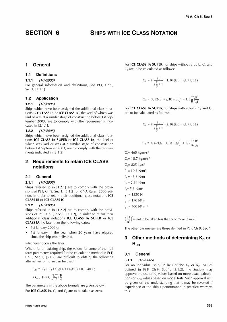
Pt A, Ch 6, Sec 6
RINA Rules 2012 363
SECTION 6 SHIPS WITH ICE CLASS NOTATION
1 General
1.1 Definitions1.1.1 (1/7/2005)For general information and definitions, see Pt F, Ch 9,Sec 1, [3.1.1]
1.2 Application1.2.1 (1/7/2005)Ships which have been assigned the additional class nota-tions ICE CLASS IB or ICE CLASS IC, the keel of which waslaid or was at a similar stage of construction before 1st Sep-tember 2003, are to comply with the requirements indi-cated in [2.1.1].
1.2.2 (1/7/2005)Ships which have been assigned the additional class nota-tions ICE CLASS IA SUPER or ICE CLASS IA, the keel ofwhich was laid or was at a similar stage of constructionbefore 1st September 2003, are to comply with the require-ments indicated in [2.1.2].
2 Requirements to retain ICE CLASS notations
2.1 General2.1.1 (1/7/2005)Ships referred to in [1.2.1] are to comply with the provi-sions of Pt F, Ch 9, Sec 1, [3.1.2] of RINA Rules, 2000 edi-tion, in order to retain their additional class notations ICECLASS IB or ICE CLASS IC.
2.1.2 (1/7/2005)Ships referred to in [1.2.2] are to comply with the provi-sions of Pt F, Ch 9, Sec 1, [3.1.2], in order to retain theiradditional class notations ICE CLASS IA SUPER or ICECLASS IA, no later than the following dates:• 1st January 2005 or• 1st January in the year when 20 years have elapsed
since the ship was delivered,
whichever occurs the later.
When, for an existing ship, the values for some of the hullform parameters required for the calculation method in Pt F,Ch 9, Sec 1, [3.1.2] are difficult to obtain, the followingalternative formulae can be used:
The parameters in the above formula are given below.
For ICE CLASS IA, C1 and C2 are to be taken as zero.
For ICE CLASS IA SUPER, for ships without a bulb, C1 andC2 are to be calculated as follows:
For ICE CLASS IA SUPER, for ships with a bulb, C1 and C2
are to be calculated as follows:
C3= 460 kg/m2s2
C4= 18,7 kg/m2s2
C5= 825 kg/s2
f1 = 10,3 N/m2
f2 = 45,8 N/m
f3 = 2,94 N/m
f4= 5,8 N/m2
g1 = 1530 N
g2 = 170 N/m
g3 = 400 N/m 1,5
The other parameters are those defined in Pt F, Ch 9, Sec 1
3 Other methods of determining KC or RCH
3.1 General3.1.1 (1/7/2005)For an individual ship, in lieu of the KC or RCH valuesdefined in Pt F, Ch 9, Sec 1, [3.1.2], the Society mayapprove the use of KC values based on more exact calcula-tions or RCH values based on model tests. Such approval willbe given on the understanding that it may be revoked ifexperience of the ship's performance in practice warrantsthis.
RCH C1 C2 C3+ + HF HM+( )2 B 0 658HF,+( )
C4LH2F C5
LTB2------
3B4---+ +
=
C1 f1BL
2TB--- 1+
----------------- 1 84 f2B f3L f4BL+ +( ),+=
C2 3 52 g1 g2B+( ), g3 1 1 2 TB---,+
B2
L-------+=
C1 f1BL
2TB--- 1+
----------------- 2 89 f2B f3L f4BL+ +( ),+=
C2 6 67 g1 g2B+( ), g3 1 1 2TB---,+
B2
L-------+=
LTB2------ 3
is not to be taken less than 5 or more than 20

Pt A, Ch 6, Sec 6
364 RINA Rules 2012
4 Draught limitation in ice
4.1 Warning triangle4.1.1 (1/7/2007)For ships built before 1 July 2007, if the UIWL (see Pt F,Ch 9, Sec 1, [2.1.1]) is below the summer load line, theship's sides are to be provided with a warning triangle andwith an ice class draught mark at the maximum permissibleice class draught amidships (see Fig 1), not later than thefirst scheduled dry docking after 1 July 2007. The purposeof the warning triangle is to provide information on thedraught limitation of the ship when it is sailing in ice forMasters of icebreakers and for inspection personnel inports.
The upper edge of the warning triangle is to be located ver-tically above the "ICE" mark, 1000 mm higher than the sum-mer load line in fresh water but in no case higher than thedeck line. The sides of the triangle are to be 300 mm inlength.
The ice class draught mark is to be located 540 mm abaftthe centre of the load line ring or 540 mm abaft the verticalline of the timber load line mark, if applicable.
The marks and figures are to be cut out of 5 - 8 mm plateand then welded to the ship's side. The marks and figuresare to be painted in a red or yellow reflecting colour so thatthey are plainly visible even in ice conditions.
The dimensions of all figures are to be the same as thoseused in the load line mark.
Figure 1 : Warning triangle (1/7/2007)
ICE230 25
SF
1000
540 mm aft
25ICE
300
I R

Pt A, Ch 6, App 1
RINA Rules 2012 365
APPENDIX 1 TECHNICAL RETROACTIVE REQUIREMENTS FOR
BULK CARRIERS
1 General
1.1
1.1.1 This Appendix contains the technical requirementsapplicable retroactively to existing ships listed in Sec 2.
2 Evaluation of scantlings of the trans-verse watertight vertically corrugated bulkheads between the two foremost cargo holds
2.1 Application and definitions
2.1.1 These requirements apply to ships indicated inSec 2, [1.1.1].
2.1.2 In these requirements, homogeneous loading condi-tion means a loading condition in which the ratio betweenthe highest and the lowest filling ratio, evaluated for the twoforemost cargo holds, does not exceed 1,20, to be correctedfor different cargo densities.
2.1.3 The net scantlings of the transverse bulkheadbetween the two foremost cargo holds are to be calculatedusing the loads given in [2.2], the bending moment andshear force given in [2.3] and the strength criteria given in[2.4].
Where necessary, steel renewal and/or reinforcements arerequired as per [2.6].
2.2 Load model
2.2.1 GeneralThe loads to be considered as acting on the bulkhead arethose given by the combination of the cargo loads withthose induced by the flooding of the foremost cargo hold.
The most severe combinations of cargo induced loads andflooding loads are to be used for the check of the scantlingsof the bulkhead, depending on the loading conditionsincluded in the loading manual:• homogeneous loading conditions• non-homogeneous loading conditions.
Non-homogeneous part loading conditions associated withmultiport loading and unloading operations for homogene-ous loading conditions need not be considered according tothese requirements.
2.2.2 Bulkhead corrugation flooding headThe flooding head hf (see Fig 1) is the distance, in m, meas-ured vertically with the ship in the upright position, fromthe calculation point to a level located at a distance df , inm, from the base line equal to:- D in general- 0,95D for ships less than 50000 t deadweight with type
B freeboard,
D being the distance, in m, from the base line to the free-board deck at side amidships (see Fig 1).
For ships to be operated at an assigned load line draught Tr
less than the permissible load line draught T, the floodinghead defined for the two cases above may be reduced by(T-Tr).

Pt A, Ch 6, App 1
366 RINA Rules 2012
Figure 1 : Calculation of pressure on the bulkhead in the flooded cargo hold
V = Volume of cargo
P = Calculation point
2.2.3 Pressure in the flooded hold: bulk cargo loaded hold
Two cases are to be considered, depending on the values ofdl and df , dl (see Fig 1) being a distance from the base linegiven, in m, by:
where:
Mc : Mass of cargo, in t, in the foremost cargo hold
ρc : Bulk cargo density, in t/m3
lc : Length of the foremost cargo hold, in m
B : Ship’s breadth amidships, in m
vLS : Volume, in m3, of the bottom stool above theinner bottom
hHT : Height of the hopper tanks amidships, in m,from the base line
hDB : Height of the double bottom, in m
bHT : Breadth of the hopper tanks amidships, in m.
a) Case when df ≥ dl
At each point of the bulkhead located at a distancebetween dl and df from the base line, the pressure pc,f , inkN/m2, is given by:
where:
ρ : Sea water density, in t/m3
g : 9,81 m/s2, gravity acceleration
hf : Flooding head as defined in [2.2.2].
At each point of the bulkhead located at a distancelower than dl from the base line, the pressure pc,f , inkN/m2, is given by:
where:
ρ, g, hf : As given above
ρc : Bulk cargo density, in t/m3
perm : Permeability of cargo, to be taken as 0,3 forore (corresponding bulk cargo density foriron ore may generally be taken as 3,0 t/m3)
hl : Vertical distance, in m, from the calculationpoint to a level located at a distance dl , asdefined above, from the base line (see Fig 1)
γ : γ = 45° - (φ/2)φ : Angle of repose of the cargo, in degrees,
and may generally be taken as 35° for ironore.
The force Fc,f , in kN, acting on a corrugation is given by:
where:s1 : Spacing of corrugations, in m (see Fig 2)ρ, g, dl, hDB : As given abovedf : As given in [2.2.2](pc,f)le : Pressure, in kN/m2, at the lower end of the
corrugationhLS : Height of the lower stool, in m, from the
inner bottom.
b) Case when df < dl
At each point of the bulkhead located at a distancebetween df and dl from the base line, the pressure pc,f , inkN/m2, is given by:
where:ρc, g, hl, γ : as given in a) aboveAt each point of the bulkhead located at a distancelower than df from the base line, the pressure pc,f , inkN/m2, is given by:
where:
D
P
h
fh
d
df
Vl
l
dlMc
ρclcB-------------
vLS
lcB------- hHT hDB–( )
bHT
B-------- hDB+ + +=
pc f, ρghf=
pc f, ρghf ρc ρ 1 perm–( )–[ ]ghl γtan2+=
Fc f, =s1 ρgdf-dl( )2
2-------------------
ρg df-dl( ) pc f,( ) le+2
---------------------------------------------- dl-hDB-hLS( )+
pc f, ρcghl γtan2=
pc f, ρghf ρchl ρ 1 perm–( )hf–[ ]g γtan2+=

Pt A, Ch 6, App 1
RINA Rules 2012 367
ρ, g, hf, ρc, hl, perm, γ : as given in a) above
The force Fc,f , in kN, acting on a corrugation is given by:
where:
s1, ρc, g, γ, (pc,f)le , hLS : As given in a) above
dl, hDB : as given in [2.2.3]
df : as given in [2.2.2].
2.2.4 Pressure in the flooded hold: empty hold
At each point of the bulkhead, the hydrostatic pressure pf
induced by the flooding head hf is to be considered.
The force Ff , in kN, acting on a corrugation is given by:
where:
s1, ρ, g, hLS :as given in [2.2.3] a)
hDB : as given in [2.2.3]
df : as given in [2.2.2].
2.2.5 Pressure in the non-flooded bulk cargo loaded hold
At each point of the bulkhead, the pressure pc , in kN/m2, isgiven by:
where:
ρc , g, hl, γ : as given in [2.2.3] a).
The force Fc , in kN, acting on a corrugation is given by:
where:
ρc , g, s1, hLS , γ : as given in [2.2.3] a)
dl, hDB : as given in [2.2.3].
2.2.6 Resultant pressure in homogeneous loading conditions
At each point of the bulkhead structures, the resultant pres-sure p, in kN/m2, to be considered for the scantlings of thebulkhead is given by:
p = pc,f - 0,8 pc
The resultant force F, in kN, acting on a corrugation is givenby:
F = Fc,f - 0,8 Fc
2.2.7 Resultant pressure in non-homogeneous loading conditions
At each point of the bulkhead structures, the resultant pres-sure p, in kN/m2, to be considered for the scantlings of thebulkhead is given by:
p = pc,f
The resultant force F, in kN, acting on a corrugation is givenby:
F = Fc,f
Where the foremost cargo hold, in non-homogeneous load-ing conditions, is not allowed to be loaded, the resultantpressure p, in kN/m2, to be considered for the scantlings ofthe bulkhead is given by:
p = pf
and the resultant force F, in kN, acting on a corrugation isgiven by:
F = Ff
2.3 Bending moment and shear force in the bulkhead corrugations
2.3.1 General
The bending moment M and the shear force Q in the bulk-head corrugations are obtained using the formulae given in[2.3.2] and [2.3.3]. The M and Q values are to be used forthe checks in [2.4].
2.3.2 Bending moment
The design bending moment M, in kN.m, for the bulkheadcorrugations is given by:
where:
F : Resultant force in kN, as given in [2.2.6] or[2.2.7]
: Span of the corrugation, in m, to be takenaccording to Fig 2 and Fig 3.
2.3.3 Shear force
The shear force Q, in kN, at the lower end of the bulkheadcorrugations is given by:
Q = 0,8 F
where:
F : As given in [2.2.6] or [2.2.7].
Fc f, s1 ρcgdl df–( )2
2---------------------- γtan2=
+s1ρcg dl df–( ) γtan2 pc f,( )le+
2----------------------------------------------------------------- df hDB– hLS–( )
Ff s1ρgdf hDB– hLS–( )2
2---------------------------------------=
pc ρcghl γtan2=
Fc s1ρcgdl hDB– hLS–( )2
2--------------------------------------- γtan2=
MF8
------=

Pt A, Ch 6, App 1
368 RINA Rules 2012
Figure 2 : Parameters of vertically corrugated bulkhead
Figure 3 : Definition of the corrugation span
(∗): For the definition of , the internal end of the upper stool is not to be taken more than a distance from the deck at the centreline equal to:
- three times the depth of corrugations, in general
- twice the depth of corrugations, for rectangular stool.
�
n=neutral axis of the corrugations
n
n
Shedder Plates When 50
a
c
tw
S1 tf
�

Pt A, Ch 6, App 1
RINA Rules 2012 369
2.4 Strength criteria
2.4.1 General
The following criteria are applicable to transverse bulk-heads with vertical corrugations (see Fig 2).
Requirements for local net plate thickness are given in[2.4.8].
In addition, the criteria given in [2.4.2] and [2.4.5] are to becomplied with.
Where the corrugation angle φ shown in Fig 2 is less than50°, a horizontal row of staggered shedder plates is to be fit-ted at approximately mid-depth of the corrugations (seeFig 2) to help preserve dimensional stability of the bulkheadunder flooding loads. The shedder plates are to be weldedto the corrugations by double continuous welding, but theyare not to be welded to the side shell.
The thicknesses of the lower part of corrugations consideredin the application of [2.4.2] and [2.4.3] are to be main-tained for a distance from the inner bottom (if no lowerstool is fitted) or the top of the lower stool not less than0,15.
The thicknesses of the middle part of corrugations consid-ered in the application of [2.4.2] and [2.4.4] are to be main-tained to a distance from the deck (if no upper stool is fitted)or the bottom of the upper stool not greater than 0,3.
2.4.2 Bending capacity and shear stress τ
The bending capacity is to comply with the following rela-tionship:
where:
M : Bending moment, in kN.m, as given in [2.3.2]
Zle : Section modulus of one half pitch corrugation,in cm3, at the lower end of corrugations, to becalculated according to [2.4.3]
Zm : Section modulus of one half pitch corrugation,in cm3, at the mid-span of corrugations, to becalculated according to [2.4.4].
σa,le : Allowable stress, in N/mm2, as given in [2.4.5],for the lower end of corrugations
σa,m : Allowable stress, in N/mm2, as given in [2.4.5],for the mid-span of corrugations.
In no case is Zm to be taken greater than the lesser of 1,15Zle
and 1,15Z’le for calculation of the bending capacity, Z’lebeing defined below.
Where effective shedders plates are fitted which:
- are not knuckled
- are welded to the corrugations and the top of the lowerstool by one side penetration welds or equivalent
- are fitted with a minimum slope of 45° and their loweredge is in line with the stool side plating,
or effective gusset plates are fitted which:
- are fitted in line with the stool side plating
- have material properties at least equal to those providedfor the flanges,
the section modulus Zle , in cm3, is to be taken not largerthan the value Z’le , in cm3, given by:
where:
Zg : Section modulus of one half pitch corrugation,in cm3, according to [2.4.4], in way of the upperend of shedder or gusset plates, as applicable
Q : Shear force, in kN, as given in [2.3.3]
hg : Height, in m, of shedders or gusset plates, asapplicable (see Fig 4, Fig 5, Fig 6, Fig 7 andFig 8)
s1 : As given in [2.2.3] a)
pg : Resultant pressure, in kN/m2, as defined in[2.2.6] and [2.2.7], calculated in way of themiddle of the shedders or gusset plates, asapplicable
σa : Allowable stress, in N/mm2, as given in [2.4.5].
Stresses τ are obtained by dividing the shear force Q by theshear area. The shear area is to be reduced in order toaccount for possible non-perpendicularity between the cor-rugation webs and flanges. In general, the reduced sheararea may be obtained by multiplying the web sectional areaby (sinφ), φ being the angle between the web and the flange.
When calculating the section moduli and the shear area,the net plate thicknesses are to be used.
The section moduli of corrugations are to be calculated onthe basis of the requirements given in [2.4.3] and [2.4.4].
2.4.3 Section modulus at the lower end of corrugations
The section modulus is to be calculated with the compres-sion flange having an effective flange width, bef , not largerthan as given in [2.4.6].
If the corrugation webs are not supported by local bracketsbelow the stool top (or below the inner bottom) in the lowerpart, the section modulus of the corrugations is to be calcu-lated considering the corrugation webs 30% effective.
a) Provided that effective shedder plates, as defined in[2.4.2], are fitted (see Fig 4 and Fig 5), when calculatingthe section modulus of corrugations at the lower end(cross-section 1 in Fig 4 and Fig 5, the area of flangeplates, in cm2, may be increased by the following value(which is not to be taken greater than: 2,5 a tf )
103 M0 5Zleσa le,, Zmσa m,+--------------------------------------------------- 1 0,≤
Zle′ Zg 103Qhg 0 5hg
2s1pg,–σa
-------------------------------------------+=
2 5a tftshσFsh
σFfl
---------,

Pt A, Ch 6, App 1
370 RINA Rules 2012
Figure 4 : Symmetrical shedder plates
Figure 5 : Asymmetrical shedder plates
where:
a : Width, in m, of the corrugation flange (seeFig 2)
tsh : Net shedder plate thickness, in mm
tf : Net flange thickness, in mm
σFsh : Minimum upper yield stress, in N/mm2, ofthe material used for the shedder plate
σFfl : Minimum upper yield stress, in N/mm2, ofthe material used for the corrugationflanges.
b) Provided that effective gusset plates, as defined in[2.4.2], are fitted (see Fig 6, Fig 7 and Fig 8) when cal-culating the section modulus of corrugations at thelower end (cross-section 1 in Fig 6, Fig 7 and Fig 8), thearea of flange plates, in cm2, may be increased by 7hgtgu,where:
hg : Height of gusset plate in m, see Fig 6, Fig 7and Fig 8, not to be taken greater thansgu/0,7
sgu : Width of the gusset plates, in mm
tgu : Net gusset plate thickness, in mm, not to betaken greater than tf
tf : Net flange thickness, in mm, based on theas-built condition.
c) If the corrugation webs are welded to a sloping stool topplate, which is at an angle not less than 45° with thehorizontal plane, the section modulus of the corruga-tions may be calculated considering the corrugationwebs fully effective. Where effective gusset plates arefitted, when calculating the section modulus of corruga-tions the area of flange plates may be increased as spec-ified in b) above. No credit can be given to shedderplates only.
For angles less than 45°, the effectiveness of the webmay be obtained by linear interporation between 30%for 0° and 100% for 45°.
Figure 6 : Symmetrical gusset/shedder plates
Figure 7 : Asymmetrical gusset/shedder plates
1
stoolLower
plateshedder
gh
1
stoolLower
plateshedder
gh
1
stoolLower
plategusset
gh
gh
1
stoollower
plategusset

Pt A, Ch 6, App 1
RINA Rules 2012 371
2.4.4 Section modulus of corrugations at cross-sections other than the lower end
The section modulus is to be calculated with the corruga-tion webs considered effective and the compression flangehaving an effective flange width bef not larger than as givenin [2.4.6].
2.4.5 Allowable stress checkThe normal and shear stresses σ and τ are not to exceed theallowable values σa and τa , in N/mm2, given by:
σa = σF
τa = 0,5 σF
where:
σF : Minimum upper yield stress, in N/mm2, of thematerial.
Figure 8 : Asymmetrical gusset/shedder platesSloping stool top plate
2.4.6 Effective width of the compression flange of corrugations
The effective width bef , in m, of the corrugation flange isgiven by:
bef = Ce a
where:
tf : Net flange thickness, in mm
a : As given in [2.4.3]
σF : Minimum upper yield stress, in N/mm2, of thematerial
E : Modulus of elasticity, in N/mm2, to be assumedequal to 206000 N/mm2 for steel.
2.4.7 Shear buckling checkThe buckling check is to be performed for the web plates atthe corrugation ends.
The shear stress τ is not to exceed the critical value τC , inN/mm2, obtained as follows:
where:σF : Minimum upper yield stress, in N/mm2, of the
material
E : Modulus of elasticity, in N/mm2, as given in[2.4.6]
t : Net thickness, in mm, of corrugation webc : Width, in m, of corrugation web (see Fig 2).
2.4.8 Local net plate thicknessThe bulkhead local net plate thickness t, in mm, is given by:
where:sw : Plate width, in m, to be taken equal to the width
of the corrugation flange or web, whichever isthe greater (see Fig 2)
p : Resultant pressure, in kN/m2, as defined in[2.2.6] and [2.2.7], at the bottom of each strakeof plating; in all cases, the net thickness of thelowest strake is to be determined using theresultant pressure at the top of the lower stool orat the inner bottom, if no lower stool is fitted, orat the top of shedders, if shedder or gusset/shed-der plates are fitted
σF : Minimum upper yield stress, in N/mm2, of thematerial.
For built-up corrugation bulkheads, when the thicknesses ofthe flange and web are different, the net thickness of thenarrower plating is to be not less than tn , in mm, given by:
where:
sn : Width, in m, of the narrower plating.The net thickness of the wider plating, in mm, is not to betaken less than the maximum of the following values:
where:
plategusset plategusset plategusset plategusset plategusset plategusset plategusset plategusset
gh
stoollower
=
=1
Ce2 25,
β------------- 1 25,
β2-------------–= for β 1 25,>
Ce 1= for β 1 25,≤
β 103atf
--- σF
E-----=
τC τE= for τEτF
2----≤
τC τF 1τF
4τE
--------– = for τE
τF
2---->
τFσF
3-------=
τE 0 9ktEt
1000c----------------
2
,=
kt 6 34,=
t 14 9swpσF
-----,=
tn 14 9snpσF
-----,=
tw 14 9swpσF
-----,=
tw440sw
2 pσF
------------------- tnp2–=
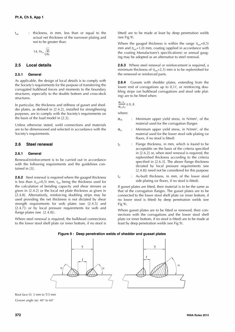
Pt A, Ch 6, App 1
372 RINA Rules 2012
tnp : thickness, in mm, less than or equal to theactual net thickness of the narrower plating andnot to be greater than:
2.5 Local details
2.5.1 General
As applicable, the design of local details is to comply withthe Society’s requirements for the purpose of transferring thecorrugated bulkhead forces and moments to the boundarystructures, especially to the double bottom and cross-deckstructures.
In particular, the thickness and stiffness of gusset and shed-der plates, as defined in [2.4.2], installed for strengtheningpurposes, are to comply with the Society’s requirements onthe basis of the load model in [2.2].
Unless otherwise stated, weld connections and materialsare to be dimensioned and selected in accordance with theSociety’s requirements.
2.6 Steel renewal
2.6.1 General
Renewal/reinforcement is to be carried out in accordancewith the following requirements and the guidelines con-tained in [3].
2.6.2 Steel renewal is required where the gauged thicknessis less than (tnet+0,5) mm, tnet being the thickness used forthe calculation of bending capacity and shear stresses asgiven in [2.4.2] or the local net plate thickness as given in[2.4.8]. Alternatively, reinforcing doubling strips may beused providing the net thickness is not dictated by shearstrength requirements for web plates (see [2.4.5] and[2.4.7]) or by local pressure requirements for web andflange plates (see [2.4.8]).
Where steel renewal is required, the bulkhead connectionsto the lower stool shelf plate (or inner bottom, if no stool is
fitted) are to be made at least by deep penetration welds(see Fig 9).
Where the gauged thickness is within the range (tnet+0,5)mm and (tnet+1,0) mm, coating (applied in accordance withthe coating Manufacturer’s specifications) or annual gaug-ing may be adopted as an alternative to steel renewal.
2.6.3 Where steel renewal or reinforcement is required, aminimum thickness of (tnet+2,5) mm is to be replenished forthe renewed or reinforced parts.
2.6.4 Gussets with shedder plates, extending from thelower end of corrugations up to 0,1, or reinforcing dou-bling strips (on bulkhead corrugations and stool side plat-ing) are to be fitted when:
where:
σFfl : Minimum upper yield stress, in N/mm2, of thematerial used for the corrugation flanges
σFs : Minimum upper yield stress, in N/mm2, of thematerial used for the lower stool side plating (orfloors, if no stool is fitted)
tfl : Flange thickness, in mm, which is found to beacceptable on the basis of the criteria specifiedin [2.6.2] or, when steel renewal is required, thereplenished thickness according to the criteriaspecified in [2.6.3]. The above flange thicknessdictated by local pressure requirements (see[2.4.8]) need not be considered for this purpose
tst : As-built thickness, in mm, of the lower stoolside plating (or floors, if no stool is fitted).
If gusset plates are fitted, their material is to be the same asthat of the corrugation flanges. The gusset plates are to beconnected to the lower stool shelf plate (or inner bottom, ifno lower stool is fitted) by deep penetration welds (seeFig 9).
Where gusset plates are to be fitted or renewed, their con-nections with the corrugations and the lower stool shelfplate (or inner bottom, if no stool is fitted) are to be made atleast by deep penetration welds (see Fig 9).
Figure 9 : Deep penetration welds of shedder and gusset plates
Root face (f): 3 mm to T/3 mm
Groove angle (α): 40° to 60°
14 9swpσF
-----,
σFstst
σFfl tfl
------------ 0 8,≤
T
f
T
f

Pt A, Ch 6, App 1
RINA Rules 2012 373
3 Guidance on renewal/reinforcement of the transverse watertight verti-cally corrugated bulkhead between the two foremost cargo holds
3.1
3.1.1 The need for renewal or reinforcement of the trans-verse watertight vertically corrugated bulkhead between thetwo foremost cargo holds will be determined by the Societyon a case-by-case basis using the criteria given in [2] inassociation with the most recent gaugings and survey find-ings.
3.1.2 In addition to Rule requirements, the assessment ofthe transverse corrugated bulkhead based on the criteriagiven in [2] will take into account the following:• scantlings of individual vertical corrugations will be
assessed for reinforcement/renewal based on thicknessmeasurements obtained in accordance with Sec 2, [1.3]at their lower end, at mid-depth and in way of platethickness changes in the lower 70%. These considera-tions will take into account the provision of gussets andshedder plates and the benefits they offer, provided thatthey comply with [2.4.2] and [2.6].
• taking into account the scantlings and arrangements foreach case, permissible levels of diminution will bedetermined and appropriate measures taken in accord-ance with [2.6].
3.1.3 Where renewal is required, its extent is to be shownclearly in plans. The vertical distance of each renewal zoneis to be determined by considering the criteria given in [2]and is generally to be not less than 15% of the vertical dis-tance between the upper and lower end of the corrugationmeasured at the ship’s centreline.
3.1.4 Where the reinforcement is accepted by addingstrips, the length of the reinforcing strips is to be sufficient toextend over the whole depth of the diminished plating. Ingeneral, the width and thickness of strips are to be sufficientto comply with the criteria given in [2]. The material of the
strips is to be the same as that of the corrugation plating.The strips are to be attached to the existing bulkhead platingby continuous fillet welds. The strips are to be suitablytapered or connected at ends in accordance with the usualwelding practice to the Surveyor’s satisfaction.
3.1.5 Where reinforcing strips are connected to the innerbottom or lower stool shelf plates, one side full penetrationwelding is to be used. When reinforcing strips are fitted tothe corrugation flange and are connected to the lower stoolshelf plate, they are normally to be aligned with strips of thesame scantlings welded to the stool side plating and havinga minimum length equal to the breadth of the corrugationflange.
3.1.6 Fig 10 gives a general arrangement of structuralreinforcement. When such reinforcement is carried out, thefollowing applies:
• square or trapezoidal corrugations are to be reinforcedwith plate strips fitted to each corrugation flange suffi-cient to meet the requirements given in [2]
• the number of strips fitted to each corrugation flange isto be sufficient to meet the requirements given in [2]
• the shedder plate may be fitted in one piece or prefabri-cated with a welded knuckle (gusset plate)
• gusset plates, where fitted, are to be welded to the shelfplate in line with the flange of the corrugation, toreduce the stress concentrations at the corrugation cor-ners. Good alignment is to be ensured between gussetplates, corrugation flanges and lower stool slopingplates. Deep penetration welding is to be used at allconnections. Start and stop of welding are to be as faraway as possible from corners of corrugations
• shedder plates are to be attached by one side full pene-tration welds onto backing bars
• shedder and gusset plates are to have a thickness equalto or greater than the original bulkhead thickness. Gus-set plates are to have a minimum height (on the verticalpart) equal to half of the width of the corrugation flange.Shedders and gussets are to be of the same material asthat of the flange.

Pt A, Ch 6, App 1
374 RINA Rules 2012
Figure 10 : Reinforcement of vertically corrugated bulkhead
Reinforcement strips with shedder and gusset plates
Weld of reinforcement strip to shelf plateReinforcement strips with shedder plate
Lower stoolplate
Gusset plate
Shedderplate
Reinforcementstrip
Lower stool side plating
Lower stoolshelf plate
Corrugationflange
Reinforcement strip
One side fullpenetrationweld
Reinforcement strip
Lower shelf plate
Gusset plate
Lower end to be taperedabove shelf plate withinline of gusset
Upper end to besuitably tapered
Flange reinforcementstrips to be aligned withstrips of same scantlingsbelow shelf plate
Lower end to be weldedto lower shelf by fullpenetration weld
Upper end to besuitably tapered
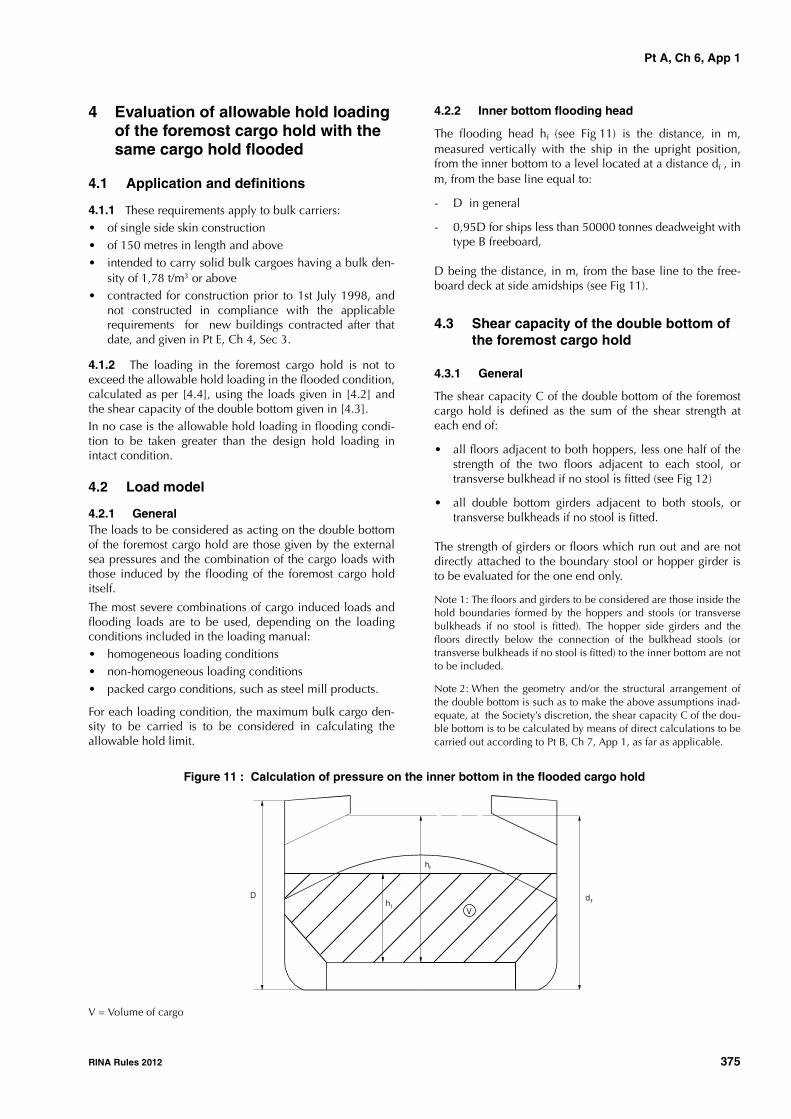
Pt A, Ch 6, App 1
RINA Rules 2012 375
4 Evaluation of allowable hold loading of the foremost cargo hold with the same cargo hold flooded
4.1 Application and definitions
4.1.1 These requirements apply to bulk carriers:• of single side skin construction• of 150 metres in length and above• intended to carry solid bulk cargoes having a bulk den-
sity of 1,78 t/m3 or above• contracted for construction prior to 1st July 1998, and
not constructed in compliance with the applicablerequirements for new buildings contracted after thatdate, and given in Pt E, Ch 4, Sec 3.
4.1.2 The loading in the foremost cargo hold is not toexceed the allowable hold loading in the flooded condition,calculated as per [4.4], using the loads given in [4.2] andthe shear capacity of the double bottom given in [4.3].In no case is the allowable hold loading in flooding condi-tion to be taken greater than the design hold loading inintact condition.
4.2 Load model
4.2.1 GeneralThe loads to be considered as acting on the double bottomof the foremost cargo hold are those given by the externalsea pressures and the combination of the cargo loads withthose induced by the flooding of the foremost cargo holditself.
The most severe combinations of cargo induced loads andflooding loads are to be used, depending on the loadingconditions included in the loading manual:• homogeneous loading conditions• non-homogeneous loading conditions• packed cargo conditions, such as steel mill products.
For each loading condition, the maximum bulk cargo den-sity to be carried is to be considered in calculating theallowable hold limit.
4.2.2 Inner bottom flooding head
The flooding head hf (see Fig 11) is the distance, in m,measured vertically with the ship in the upright position,from the inner bottom to a level located at a distance df , inm, from the base line equal to:
- D in general
- 0,95D for ships less than 50000 tonnes deadweight withtype B freeboard,
D being the distance, in m, from the base line to the free-board deck at side amidships (see Fig 11).
4.3 Shear capacity of the double bottom of the foremost cargo hold
4.3.1 General
The shear capacity C of the double bottom of the foremostcargo hold is defined as the sum of the shear strength ateach end of:
• all floors adjacent to both hoppers, less one half of thestrength of the two floors adjacent to each stool, ortransverse bulkhead if no stool is fitted (see Fig 12)
• all double bottom girders adjacent to both stools, ortransverse bulkheads if no stool is fitted.
The strength of girders or floors which run out and are notdirectly attached to the boundary stool or hopper girder isto be evaluated for the one end only.
Note 1: The floors and girders to be considered are those inside thehold boundaries formed by the hoppers and stools (or transversebulkheads if no stool is fitted). The hopper side girders and thefloors directly below the connection of the bulkhead stools (ortransverse bulkheads if no stool is fitted) to the inner bottom are notto be included.
Note 2: When the geometry and/or the structural arrangement ofthe double bottom is such as to make the above assumptions inad-equate, at the Society’s discretion, the shear capacity C of the dou-ble bottom is to be calculated by means of direct calculations to becarried out according to Pt B, Ch 7, App 1, as far as applicable.
Figure 11 : Calculation of pressure on the inner bottom in the flooded cargo hold
V = Volume of cargo
D
hf
hV
dfl

Pt A, Ch 6, App 1
376 RINA Rules 2012
Figure 12 : Double bottom structure
In calculating the shear strength, the net thicknesses offloors and girders are to be used. The net thickness tnet , inmm, is given by:
tnet = t - tC
where:
t : As-built thickness, in mm, of floors and girders
tC : Corrosion diminution, equal to 2 mm, in gen-eral; a lower value of tC may be adopted, pro-vided that measures are taken, to the Society’ssatisfaction, to justify the assumption made.
4.3.2 Floor shear strengthThe floor shear strength in way of the floor panel adjacent tohoppers Sf1 , in kN, and the floor shear strength in way ofthe openings in the outermost bay (i.e. that bay which isclosest to the hopper) Sf2 , in kN, are given by the followingexpressions:
where:
Af : Sectional area, in mm2, of the floor panel adja-cent to hoppers
Af,h : Net sectional area, in mm2, of the floor panelsin way of the openings in the outermost bay (i.e.that bay which is closest to the hopper)
τa : Allowable shear stress, in N/mm2, to be takenequal to :
σF : Minimum upper yield stress, in N/mm2, of thematerial
η1 : η1 = 1,10
η2 : η2 = 1,20
η2 may be reduced, at the Society’s discretion,down to 1,10 where appropriate reinforcementsare fitted to the Society’s satisfaction.
4.3.3 Girder shear strength
The girder shear strength in way of the girder panel adjacentto stools (or transverse bulkheads, if no stool is fitted) Sg1 , inkN, and the girder shear strength in way of the largest open-ing in the outermost bay (i.e. that bay which is closest to thestool, or transverse bulkhead, if no stool is fitted) Sg2 , in kN,are given by the following expressions:
where:
Ag : Minimum sectional area, in mm2, of the girderpanel adjacent to stools (or transverse bulk-heads if no stools are fitted)
Ag,h : Net sectional area, in mm2, of the girder panelin way of the largest opening in the outermostbay (i.e. that bay which is closest to the stool, ortransverse bulkhead, if no stool is fitted)
τa : Allowable shear stress, in N/mm2, as given in[4.3.2]
η1 : η1 = 1,10
Lower stool
Floor adjacentto the stool
Transverse bulkhead
Floor adjacent to thetransverse bulkhead
Girders
Floors
CL
Sf1 10 3– Afτa
η1
-----=
Sf2 10 3– Af h,τa
η2
-----=
τaσF
3-------=
Sg1 10 3– Agτa
η1
-----=
Sg2 10 3– Ag h,τa
η2
-----=

Pt A, Ch 6, App 1
RINA Rules 2012 377
η2 : η2 = 1,15
η2 may be reduced, at the Society’s discretion,down to 1,10 where appropriate reinforcementsare fitted to the Society’s satisfaction.
4.4 Allowable hold loading
4.4.1 The allowable hold loading W, in t, is given by:
where:F : equal to 1,05 in general (for steel mill products,
F = 1)ρc : Cargo density, in t/m3; for bulk cargoes see
[4.2.1]; for steel products, ρc is to be taken asthe density of steel
V : Volume, in m3, occupied by cargo at a level h1
given by:
where:X : for bulk cargoes, is the lesser of X1 and X2 given
by:
Note 1: For steel products, X may be taken equal to X1, usingperm=0.
ρ : Sea water density, in t/m3
g : 9,81 m/s2, gravity accelerationE : E = df - 0,1 D
with df and D as given in [4.2.2]
hf : Flooding head, in m, as defined in [4.2.2]perm : Permeability of cargo, to be taken as 0,3 for ore
(corresponding bulk cargo density for iron oremay generally be taken as 3,0 t/m3)
Z : The lesser of Z1 and Z2 given by:
with:Ch : Shear capacity of the double bottom, in kN, as
defined in [4.3], considering, for each floor, thelesser of the shear strengths Sf1 and Sf2 (see[4.3.2]) and, for each girder, the lesser of theshear strengths Sg1 and Sg2 (see [4.3.3])
Ce : Shear capacity of the double bottom, in kN, asdefined in [4.3], considering, for each floor, theshear strength Sf1 (see [4.3.2]) and, for eachgirder, the lesser of the shear strengths Sg1 andSg2 (see [4.3.3])
ADB,h :
ADB,e :
where:n : number of floors between stools (or transverse
bulkheads, if no stools are fitted)Si : Space of ith-floor, in mBDB,i : • for floors whose shear strength is given by
Sf1 (see [4.3.2]) : BDB,i = BDB - s
• for floors whose shear strength is given bySf2 (see [4.3.2]) : BDB,i = BDB,h
where BDB,h is the distance, in m, between thetwo openings considered (see Fig 13)
BDB : Breadth of double bottom, in m, between hop-pers (see Fig 13)
s : Spacing, in m, of double bottom longitudinalsadjacent to hoppers.
Figure 13 : Dimensions BDB and BDB,h
W ρcV1F---=
h1X
ρcg--------=
X1Z ρg E hf–( )+
1 ρρc
----- perm 1–( )+--------------------------------------------=
X2 Z ρg E hfperm–( )+=
Z1Ch
ADB h,-------------=
Z2Ce
ADB e,------------=
ADB h, SiBDB i,
i 1=
i n=
=
ADB e, Si BDB s–( )i 1=
i n=
=
BDB,h
BDB

Pt A, Ch 6, App 2
378 RINA Rules 2012
APPENDIX 2 GUIDELINES FOR THE THICKNESS MEASURE-MENTS OF SIDE SHELL FRAMES AND BRACKETS
IN SINGLE SIDE SKIN BULK CARRIERS SUBJECT
TO COMPLIANCE WITH THE REQUIREMENTS OF
SECTION 2, [7]
1 General
1.11.1.1 (2/4/2004)Thickness measurements are necessary to determine thegeneral condition of the structure and to define the extent ofpossible steel renewals or other measures for the webs andflanges of side shell frames and brackets for verification ofcompliance with the requirements of Sec 2, [7].
2 Zones of side shell frames and brackets
2.12.1.1 (2/4/2004)For the purpose of steel renewal, sandblasting and coating,four zones A, B, C and D are defined, as shown in Fig 1.Zones A and B are considered to be the most critical zones.
3 Pitting and grooving
3.1 General3.1.1 (2/4/2004)Pits can grow in a variety of shapes, some of which wouldneed to be ground before assessment. Pitting corrosion maybe found under coating blisters, which are to be removedbefore inspection. To measure the remaining thickness ofpits or grooving the normal ultrasonic transducer (generally10mm diameter) will not suffice. A miniature transducer (3to 5 mm diameter) is to be used. Alternatively the gaugingfirm is to use a pit gauge to measure the depth of the pitsand grooving and calculate the remaining thickness.
3.2 Assessment based upon area3.2.1 (1/7/2006)This is the method specified in Sec 2, [7.5.7] and is basedupon the intensity determined from Figure 2.
If pitting intensity is higher than 15% in an area (see Fig 2),then thickness measurements are to be taken to check theextent of the pitting corrosion. The 15% is based upon pit-ting or grooving on only one side of the plate.
In cases where pitting is evident as defined above (exceed-ing 15%), then an area of 300mm diameter or more (or an
equivalent rectangular area, where this is impracticable onthe frame flange or the side shell, hopper tank plating ortopside tank plating attached to the side frame), at the mostpitted part, is to be cleaned to bare metal, and the thicknessmeasured in way of the five deepest pits within the cleanedarea. The least thickness measured in way of any of thesepits is to be taken as the thickness to be recorded.
The minimum acceptable remaining thickness in any pit orgroove is equal to:
• 75% of the as-built thickness, for pitting or grooving inthe cargo hold side frame webs and flanges
• 70% of the as-built thickness, for pitting or grooving inthe side shell, hopper tank and topside tank platingattached to the cargo hold side frame, over a width upto 30 mm from each side of it.
Figure 1 : Zones of side shell frames and brackets (2/4/2004)
0,25
h0,
25h
h
Lower part of
side frame
B
A
C
D

Pt A, Ch 6, App 2
RINA Rules 2012 379
Figure 2 : Pitting intensity diagrams (from 5% to 25% intensity) (2/4/2004)
4 Gauging methodology
4.1 General4.1.1 (2/4/2004)The numbers of side frames to be measured are equivalentto those of class renewal survey or intermediate survey cor-responding to the ship's age. Representative thicknessmeasurements are to be taken for each zone as specifiedbelow.
Special consideration may be given to the extent of thethickness measurements if the structural members show nothickness diminution with respect to the as-built thicknessesand the coating is found in "as-new" condition (i.e. withoutbreakdown or rusting).
Where gauging readings close to the criteria are found, thenumber of hold frames to be measured is to be increased.
If renewal or other measures according to Sec 2, [7] are tobe applied on individual frames in a hold, then all frames inthat hold are to be gauged.
There are a variety of construction methods used for sideshell frames in bulk carriers. Some have faceplates (T sec-tions) on the side shell frames, some have flanged platesand some have bulb plates. The use of faceplates andflanged sections is considered similar for gauging purposesin that both the web and faceplate or web and flange plateare to be gauged. If a bulb plate has been used, then theweb of the bulb plate is to be gauged in the normal mannerand the sectional modulus is to be specially considered, ifrequired.
4.2 Gauging for Zones A, B and D - Web plating
4.2.1 (2/4/2004)The gauging pattern for Zones A, B and D is to be a five-point pattern (see Fig 3). The five-point pattern is to be overthe depth of the web and the same area vertically. The gaug-ing report is to reflect the average reading.
Figure 3 : Typical five-point pattern on the web plate (2/4/2004)
4.3 Gauging for Zone C - Web plating4.3.1 (2/4/2004)Depending upon the condition of the web in way of ZoneC, the web may be measured by taking 3 readings over thelength of Zone C and averaging them. The average reading
5% SCATTERED 20% SCATTERED
15% SCATTERED
10% SCATTERED 25% SCATTERED
Side shell
Face Plate
Web
W mm
X
W mm
XX
X
X

Pt A, Ch 6, App 2
380 RINA Rules 2012
is to be compared with the allowable thickness. If the webplating has general corrosion then this pattern should beexpanded to a five-point pattern as noted above.
4.4 Gauging for sections a) and b) (flanges and side shell plating)
4.4.1 (2/4/2004)Where the lower bracket length or depth does not meet therequirements in Pt E, Ch 4, Sec 3, [6.2], gauging readingsare to be taken at sections a) and b) to calculate the actualsection modulus required in Sec 2, [7.6.7] (see Fig 4). Atleast 2 readings on the flange/faceplate are to be taken inway of each section. At least one reading of the attached
shell plating is to be taken on each side of the frame (i.e.fore and aft) in way of section a) and section b).
5 Report on thickness measurements of cargo hold frames
5.1
5.1.1 (2/4/2004)
The thickness measurements of the cargo hold frames takenas required above for verification of compliance with therequirements of Sec 2, [7] are recorded in the appropriateform where the four zones A, B, C and D are indicated.
Figure 4 : Sections a) and b) (2/4/2004)
Section b)
Section a)
db
da
hB
da = lower bracket web depthfor determining t
db = frame web depth
hB = lower bracket length
REN.S