Embed Size (px)
Citation preview
Slide 1
Part II명령어 집합 구조
Parts Chapters
I. 배경과 동기
1. 조합논리회로2. 메모리가 있는 디지털 회로3. 컴퓨터 시스템 기술4. 컴퓨터 성능
II. 명령어 집합 구조
5. 명령어와 주소지정6. 프로시저와 데이터7. 어셈블리어 프로그램8. 명령어 세트의 다양성
C
P
U
III. 산술/논리 장치
9. 수의 표현10. 덧셈기와 간단한 ALU11. 곱셈기와 나눗셈기12. 부동소수점연산
IV. 데이터 경로와 제어
13. 명령어 실행단계14. 제어장치합성15. 파이프라인화된 데이터 경로16. 파이프라인 성능의 제한
V. 메모리 시스템 설계
17. 주기억장치 개념18. 캐시메모리 구성19. 대용량메모리의 개념20. 가상메모리와 페이징
VI. 입력/출력 및 인터페이스
21. 입력/출력 장치22. 입력/출력 프로그래밍23. 버스, 링크 및 인터페이스24. 컨텍스트 스위칭과 인터럽트
VII. 고급 컴퓨터 구조
25. 고성능의 방안26. 벡터 및 배열 프로세싱27. 공유 메모리 다중 프로세싱28. 분산 다중 컴퓨팅

Computer Architecture, Instruction-Set Architecture
Slide 2
II 명령어 집합 구조
Topics in This PartChapter 5 명령어와 주소지정
Chapter 6 프로시저와 데이터
Chapter 7 어셈블리어 프로그램
Chapter 8 명령어 세트의 다양성
Computer Architecture, Instruction-Set Architecture
Slide 3
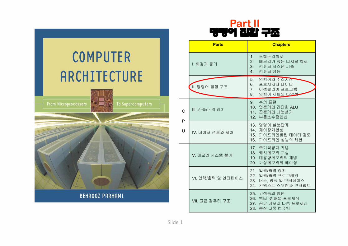
5 명령어와 주소지정
Topics in This Chapter
5.1 하드웨어의 추상적 관점
5.2 명령어 형식
5.3 간단한 산술 및 논리 명령어
5.4 적재 명령어와 저장 명령어
5.5 점프 명령어와 분기 명령어
5.6 주소지정방식
앞의 두 장은 MiniMIPS의 명령어 집합에 관한 것이다:• 뒷 부분에서 요구되는 하드웨어의 개념• 어셈블러 프로그래밍을 익히기 위한 것은 아니다.

Computer Architecture, Instruction-Set Architecture
Slide 4
5.1 하드웨어의 추상적 관점
Figure 5.1 MiniMIPS의 메모리 및 데이터 처리 서브시스템
Memory up to 2 words 30
Loc 0 Loc 4 Loc 8
Loc m - 4
Loc m - 8
4 B / location
m £ 2 32
$0 $1 $2
$31
Hi Lo
ALU
$0 $1 $2
$31 FP
arith
EPC Cause
BadVaddr Status
EIU FPU
TMU
Execution & integer unit
Floating- point unit
Trap & memory unit
. . .
. . .
(Coproc. 1)
(Coproc. 0)
(Main proc.)
Integer mul/div
Chapter 10
Chapter 11
Chapter 12

Computer Architecture, Instruction-Set Architecture
Slide 5
Data Types
MiniMIPS 레지스터는 32-bit (4-byte)워드를 저장한다. 그 외에도 일반적인 데이터 크기인 byte, halfword 및 doubleword도 저장할 수 있는 레지스터도 있다.
Byte
Halfword
Word
Doubleword
Halfword = 2 bytes
Byte = 8 bits
Word = 4 bytes
Doubleword = 8 bytes

Computer Architecture, Instruction-Set Architecture
Slide 6
레지스터규정
Figure 5.2 MiniMIPS의레지스터와 데이터 크기
Temporary values
More temporaries
Operands
Global pointer Stack pointer Frame pointer Return address
Saved
Saved Procedure arguments
Saved across
procedure calls
Procedure results
Reserved for assembler use
Reserved for OS (kernel)
$0 $1 $2 $3 $4 $5 $6 $7 $8 $9 $10 $11 $12 $13 $14 $15 $16 $17 $18 $19 $20 $21 $22 $23 $24 $25 $26 $27 $28 $29 $30 $31
0
$zero
$t0
$t2
$t4
$t6
$t1
$t3
$t5
$t7 $s0
$s2
$s4
$s6
$s1
$s3
$s5
$s7 $t8 $t9
$gp $sp $fp $ra
$at
$k0 $k1
$v0 $a0 $a2
$v1 $a1 $a3
A doubleword sits in consecutive registers or memory locations according to the big-endian order (most significant word comes first)
When loading a byte into a register, it goes in the low end Byte
Word
Doublew ord
Byte numbering: 0 1 2 3
3 2 1 0
A 4-byte word sits in consecutive memory addresses according to the big-endian order (most significant byte has the lowest address)
어셈블러가 사용하기 위해 예약
프로시저 결과
프로시저매개변수
임시값
피 연산자
추가임시 값
운영체제(커널) 예약
전역 포인터스택 포인터프레임 포인터반환 주소
저장됨
프로시저호출할 때저장 됨
저장됨
4바이트 워드는big-endian 순서에 따라 연속적인메모리 주소에 저장됨(최상위 바이트가 가장 낮은 주소에 저장됨)
한 바이트를 레지스터에 읽어올때 가장 끝으로간다.
Doubleword가연속적인 레지스터 또는 메모리에 저장될 때big-endian 순서에 따른다.(최상위 워드가먼저 온다)


Computer Architecture, Instruction-Set Architecture
Slide 8
5.2 명령어 형식
Figure 5.3 MiniMIPS의 전형적인 명령어와 이를 수행해 가는 단계들
Assembly language instruction:
Machine language instruction:
High-level language statement:
000000 10010 10001 11000 00000 100000
add $t8, $s2, $s1
a = b + c
ALU-type instruction
Register 18
Register 17
Register 24 Unused
Addition opcode
ALU
Instruction fetch
Register readout
Operation
Data read/store
Register writeback
Register file
Instruction
cache
Data cache (not used)
Register file
P C
$17 $18
$24
고급 언어의 문장 :
어셈블리어 명령 :
기계어 명령 :
명령 캐시
레지스터파일
명령어 인출
레지스터읽기
연산
데이터 캐시(사용하지 않음)
데이터읽기/저장
레지스터저장
레지스터파일

Computer Architecture, Instruction-Set Architecture
Slide 9
상수의 덧셈, 뺄셈 및 명세
MiniMIPS의 덧셈과 뺄셈 명령; 즉, 계산: g = (b + c) - (e + f)add $t8,$s2,$s3 # put the sum b + c in $t8add $t9,$s5,$s6 # put the sum e + f in $t9sub $s7,$t8,$t9 # set g to ($t8) - ($t9)
10진과 16진 상수(Decimal and hex constants)
Decimal 25, 123456, -2873Hexadecimal 0x59, 0x12b4c6, 0xffff0000
기계어 명령어는 일반적으로 다음 내용을 가진다.
명령코드(an opcode)한 개 이상의 소스 오퍼랜드(one or more source operands)하나의 목적지 오퍼랜드(possibly a destination operand)

Computer Architecture, Instruction-Set Architecture
Slide 10
MiniMIPS 명령어 형식
Figure 5.4 MiniMIPS 명령어는 단 세 가지 형식만을 갖는다: register (R), immediate (I, 즉치), and jump (J).
5 bits 5 bits 31 25 20 15 0
Opcode Source register 1
Source register 2
op rs rt
R 6 bits 5 bits
rd
5 bits
sh
6 bits 10 5
fn
Destination register
Shift amount
Opcode extension
Immediate operand or address offset
31 25 20 15 0
Opcode Destination or data
Source or base
op rs rt operand / offset
I 5 bits 6 bits 16 bits 5 bits
0 0 0 0 0 0 0 0 0 0 0 1 1 1 1 1 1 0 0 0 0 0 0 0 0 0 31 0
Opcode
op jump target address
J Memory word address (byte address divided by 4)
26 bits 25
6 bits
Computer Architecture, Instruction-Set Architecture
Slide 11
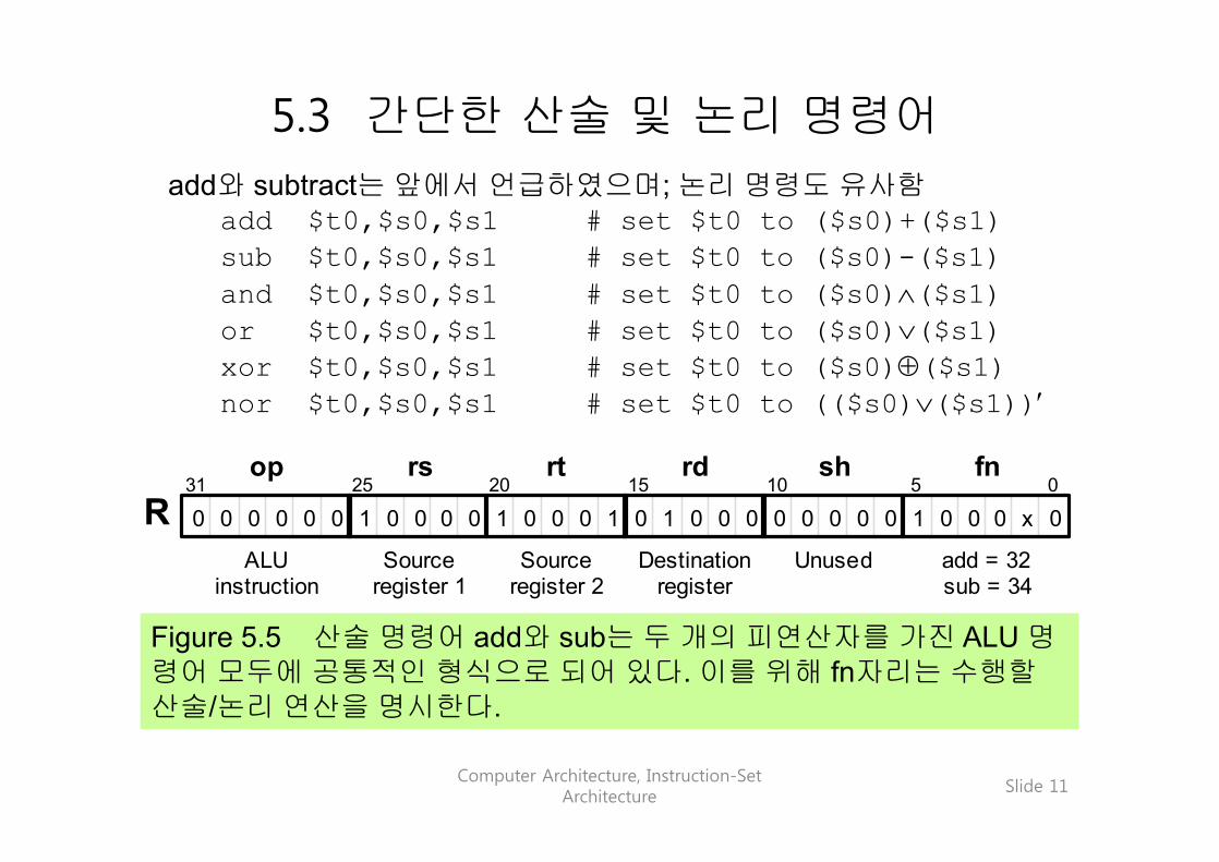
5.3 간단한 산술 및 논리 명령어
Figure 5.5 산술 명령어 add와 sub는 두 개의 피연산자를 가진 ALU 명령어 모두에 공통적인 형식으로 되어 있다. 이를 위해 fn자리는 수행할산술/논리 연산을 명시한다.
0 0 0 0 0 0 0 0 0 0 0 0 0 0 0 1 x 0 0 1 1 1 1 0 0 0 0 0 0 0 0 0 31 25 20 15 0
ALU instruction
Source register 1
Source register 2
op rs rt
R rd sh
10 5 fn
Destination register
Unused add = 32 sub = 34
add와 subtract는 앞에서 언급하였으며; 논리 명령도 유사함add $t0,$s0,$s1 # set $t0 to ($s0)+($s1)sub $t0,$s0,$s1 # set $t0 to ($s0)-($s1)and $t0,$s0,$s1 # set $t0 to ($s0)Ù($s1)or $t0,$s0,$s1 # set $t0 to ($s0)Ú($s1)xor $t0,$s0,$s1 # set $t0 to ($s0)Å($s1)nor $t0,$s0,$s1 # set $t0 to (($s0)Ú($s1))¢

Computer Architecture, Instruction-Set Architecture
Slide 12
하나의 즉치 오퍼랜드를 가진 산술/논리 연산
Figure 5.6 addi와 같은 명령어는 하나의 피연산자가 작은 상수로 되어있는 산술 또는 논리 연산의 수행이 가능하도록 해 준다.
0 0 0 0 0 0 0 0 0 0 0 0 0 0 1 1 1 1 1 0 0 1 1 0 0 0 0 0 0 0 0 31 25 20 15 0
addi = 8 Destination Source Immediate operand
op rs rt operand / offset
I 1
하나의 오퍼랜드의 범위가 [-32 768, 32 767], 또는 [0x0000, 0xffff]일 때 즉치 영역에 지정될 수 있다.
addi $t0,$s0,61 # set $t0 to ($s0)+61andi $t0,$s0,61 # set $t0 to ($s0)Ù61ori $t0,$s0,61 # set $t0 to ($s0)Ú61xori $t0,$s0,0x00ff # set $t0 to ($s0)Å 0x00ff
산술 명령어 대해서 즉치 오퍼랜드는 부호-확장이 된다.

Computer Architecture, Instruction-Set Architecture
Slide 13
5.4 적재 명령어와 저장 명령어
Figure 5.7 기준 주소와 오프셋 (offset = 4i 는 ith word에 이르게 한다)을 통하여 배열 요소에 대한 간단한 엑세스가 가능하도록 해 주는MiniMIPS의 lw 및 sw 명령어와 이들의 메모리 주소지정 규약
0 0 0 0 0 0 0 0 0 0 0 0 1 0 0 x 1 0 0 0 0 0 0 31 25 20 15 0
lw = 35 sw = 43
Base register
Data register
Offset relative to base
op rs rt operand / offset
I 1 1 0 0 1 1 1 1 1
A[0] A[1] A[2]
A[i]
Address in base register
Offset = 4i
.
.
.
Memory
Element i of array A
Note on base and offset: The memory address is the sum of (rs ) and an immediate value. Calling one of these the base and the other the offset is quite arbitrary. It would make perfect sense to interpret the address A($s3) as having the base A and the offset ($s3). However, a 16-bit base confines us to a small portion of memory space.
베이스와 옵셋:메모리 주소는 (rs)와 즉치 값의합이다. 이 둘 중에 하나는베이스이며, 다른 하나는옵셋인데 이를 이용하여임의적으로 호출할 수 있다.주소 A($s3)는 베이스 A와옵셋 ($s3)을 결합하여정확하게 만들 수 있다.그러나 16비트 베이스는작은 메모리 공간으로제한된다.

Computer Architecture, Instruction-Set Architecture
Slide 14
lw, sw 및 lui 명령
Figure 5.8 lui 명령어는 레지스터의 상위 절반에 임의의 16비트 값을적재시키고 하위 절반에는 0으로 채울 수 있게 해 준다.
0
0 0 0 0 0 0 0 0 0 0 0 1 1 1 1 1 0 0 0 0 0 0 0 0 0 0 0 0 0 0 0 0
0 0 0 0 0 0 0 0 0 0 0 1 1 1 1 1 0 0 1 1 1 1 1 0 0 0 0 0 0 0 0 31 25 20 15 0
lui = 15 Destination Unused Immediate operand
op rs rt operand / offset
I
Content of $s0 after the instruction is executed
lw $t0,40($s3) # load mem[40+($s3)] in $t0sw $t0,A($s3) # store ($t0) in mem[A+($s3)]
# “($s3)” means “content of $s3”lui $s0,61 # The immediate value 61 is
# loaded in upper half of $s0# with lower 16b set to 0s

Computer Architecture, Instruction-Set Architecture
Slide 15
레지스터의 초기화
Example 5.2
다음과 같은 비트 패턴들을 어떻게 $s0에 적재할 수 있는지 보여라.
0010 0001 0001 0000 0000 0000 0011 11011111 1111 1111 1111 1111 1111 1111 1111
Solution
첫 번째 비트 패턴을 16진수로 표시하면 : 0x2110003dlui $s0,0x2110 # put the upper half in $s0ori $s0,0x003d # put the lower half in $s0
같은 방법으로 두 번째 비트 패턴에 대해서는 즉치값을 0xffff 으로바꾸면 된다. 그러나 다음과 같이 하면 더 간단하다:
nor $s0,$zero,$zero # because (0 Ú 0)¢ = 1

Computer Architecture, Instruction-Set Architecture
Slide 16
5.5 점프 및 분기 명령어
무조건 점프 및 점프는 레지스터 명령을 이용한다.j verify # go to mem loc named “verify”jr $ra # go to address that is in $ra;
# $ra may hold a return address
Figure 5.9 MiniMIPS의 점프 명령어 j는 J-형식 명령어로서 유효 목표 주소를 얻는 방법을 보여준다. 점프 레지스터 명령어(jr)는 R-형식으로서 그 명시된 레지스터는 보통 $ra가 된다.
0
0 0 0 0 0 0 0 1 1 1 1 1 0 0 0 0 0 0 0 0 0 0 0 0 0 0 0 0
0 0 0 0 0 0 0 0 0 0 0 1 1 1 1 1 0 0 1 0 0 0 0 0 0 0 0 0 31 0
j = 2
op jump target address
J
Effective target address (32 bits)
25
From PC
0 0
x x x x
0 0 0 1 1 1 1 0 0 0 0 0 0 0 0 0 0 0 0 0 0 0 0 0 0 0 1 1 0 0 0 0 31 25 20 15 0
ALU instruction
Source register
Unused
op rs rt
R rd sh
10 5 fn
Unused Unused jr = 8

Computer Architecture, Instruction-Set Architecture
Slide 17
조건 분기 명령어
Figure 5.10 (part 1) MiniMIPS의 조건 분기명령어
조건 분기는 PC-상대 주소를 이용한다.bltz $s1,L # branch on ($s1)< 0beq $s1,$s2,L # branch on ($s1)=($s2)bne $s1,$s2,L # branch on ($s1)¹($s2)
0 1 0 0 0 0 0 0 0 0 0 0 0 0 0 0 1 1 1 1 1 0 0 1 1 0 0 0 0 0 0 31 25 20 15 0
bltz = 1 Zero Source Relative branch distance in words
op rs rt operand / offset
I 0
1 1 0 0 x 0 0 0 0 0 0 0 0 0 0 0 1 1 1 1 1 0 0 1 1 0 0 0 0 0 0 31 25 20 15 0
beq = 4 bne = 5
Source 2 Source 1 Relative branch distance in words
op rs rt operand / offset
I 1

Computer Architecture, Instruction-Set Architecture
Slide 18
조건 분기 명령어 필요한 비교 명령어
Figure 5.10 (part 2) MiniMIPS의 비교 명령어
slt $s1,$s2,$s3 # if ($s2)<($s3), set $s1 to 1 # else set $s1 to 0;# often followed by beq/bne
slti $s1,$s2,61 # if ($s2)<61, set $s1 to 1# else set $s1 to 0
1 1 1 0 1 1 1 0 0 0 1 1 0 0 0 0 0 0 0 0 0 0 0 0 0 0 0 0 1 1 0 0 31 25 20 15 0
ALU instruction
Source 1 register
Source 2 register
op rs rt
R rd sh
10 5 fn
Destination Unused slt = 42
1 1 1 0 0 0 0 0 0 0 0 0 0 0 0 0 1 1 1 1 1 0 0 1 1 0 0 0 0 0 0 31 25 20 15 0
slti = 10 Destination Source Immediate operand
op rs rt operand / offset
I 1

Computer Architecture, Instruction-Set Architecture
Slide 19
조건 분기 예
분기 목적지가 16비트 오프셋으로는 도달하지 못하는 경우(드뭄), 어셈블러는 자동적으로 분기명령 beq $s0,$s1,L1을 다음과 같이 대치한다:
bne $s1,$s2,L2 # skip jump if (s1)¹(s2)j L1 # goto L1 if (s1)=(s2)
L2: ...if-then 구조의 형식; e.g., if (i == j) x = x + y
bne $s1,$s2,endif # branch on i¹jadd $t1,$t1,$t2 # execute the “then” part
endif: ...조건이(i < j)라면, 첫 번째 줄을 다음과 같이 변경하면 된다 :
slt $t0,$s1,$s2 # set $t0 to 1 if i<jbeq $t0,$0,endif # branch if ($t0)=0;
# i.e., i not< j or i³j

Computer Architecture, Instruction-Set Architecture
Slide 20
Example 5.3 if-then-else 문장의 컴파일
다음에 해당하는 프로그램을 MiniMIPS 명령어로 보여라.
if (i<=j) x = x+1; z = 1; else y = y–1; z = 2*zSolution
“if-then” 문과 유사하지만, “else”부분에 해당하는 명령들이 필요하며,“then” 부분 다음에 “else”부분을 건너 뛸 방법이 있어야 한다.
slt $t0,$s2,$s1 # j<i? (inverse condition)bne $t0,$zero,else # if j<i goto else partaddi $t1,$t1,1 # begin then part: x = x+1addi $t3,$zero,1 # z = 1j endif # skip the else part
else: addi $t2,$t2,-1 # begin else part: y = y–1add $t3,$t3,$t3 # z = z+z
endif:...
Computer Architecture, Instruction-Set Architecture
Slide 21
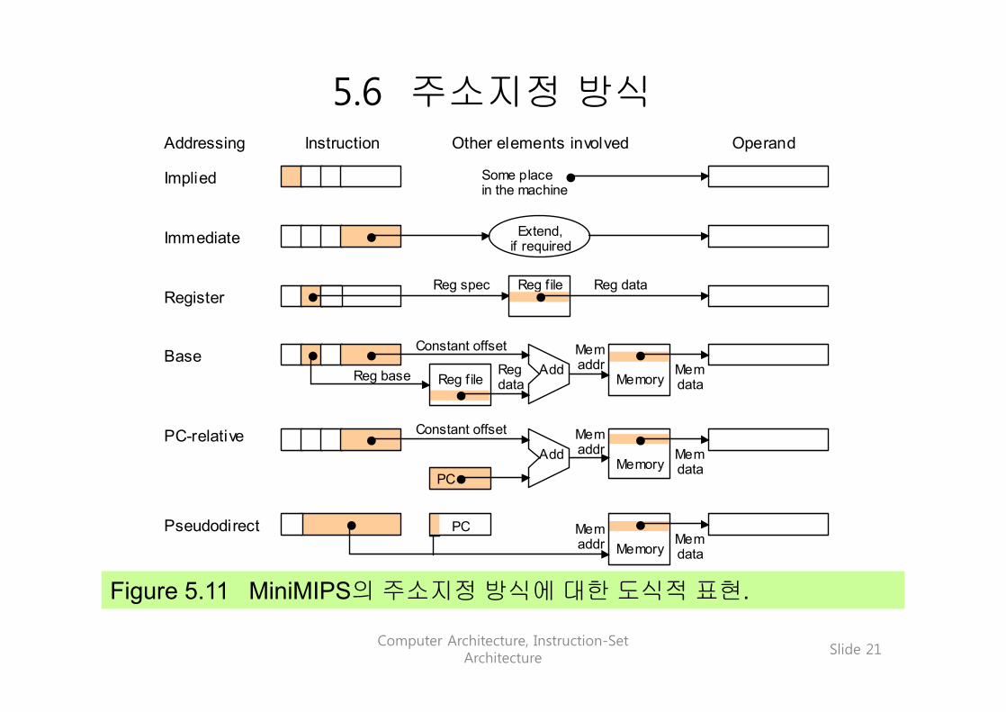
5.6 주소지정 방식
Figure 5.11 MiniMIPS의 주소지정 방식에 대한 도식적 표현.
Addressing Instruction Other elements involved Operand
Implied
Immediate
Register
Base
PC-relative
Pseudodirect
Some place in the machine
Extend, if required
Reg f ile Reg spec Reg data
Memory Add
Reg f ile
Mem addr
Constant offset
Reg base Reg data
Mem data
Add
PC
Constant offset
Memory
Mem addr Mem
data
Memory Mem data
PC Mem addr

Computer Architecture, Instruction-Set Architecture
Slide 22
Example 5.5
정수 배열 중에서 최댓값을 찾는다.
배열 A가 $s1에 저장된 주소의 첫 번째에 저장되어 있다.배열의 길이는 $s2에 저장되어 있다. 배열에서 최댓값을 찾고, 그것을 $t0로 복사하라.
Solution
배열을 검색하고, 최댓값을 찾아서 $t0에 저장한다.lw $t0,0($s1) # initialize maximum to A[0]addi $t1,$zero,0 # initialize index i to 0
loop: add $t1,$t1,1 # increment index i by 1beq $t1,$s2,done # if all elements examined, quitadd $t2,$t1,$t1 # compute 2i in $t2add $t2,$t2,$t2 # compute 4i in $t2add $t2,$t2,$s1 # form address of A[i] in $t2lw $t3,0($t2) # load value of A[i] into $t3slt $t4,$t0,$t3 # maximum < A[i]?beq $t4,$zero,loop # if not, repeat with no changeaddi $t0,$t3,0 # if so, A[i] is the new maximumj loop # change completed; now repeat
done: ... # continuation of the program
Computer Architecture, Instruction-Set Architecture
Slide 23
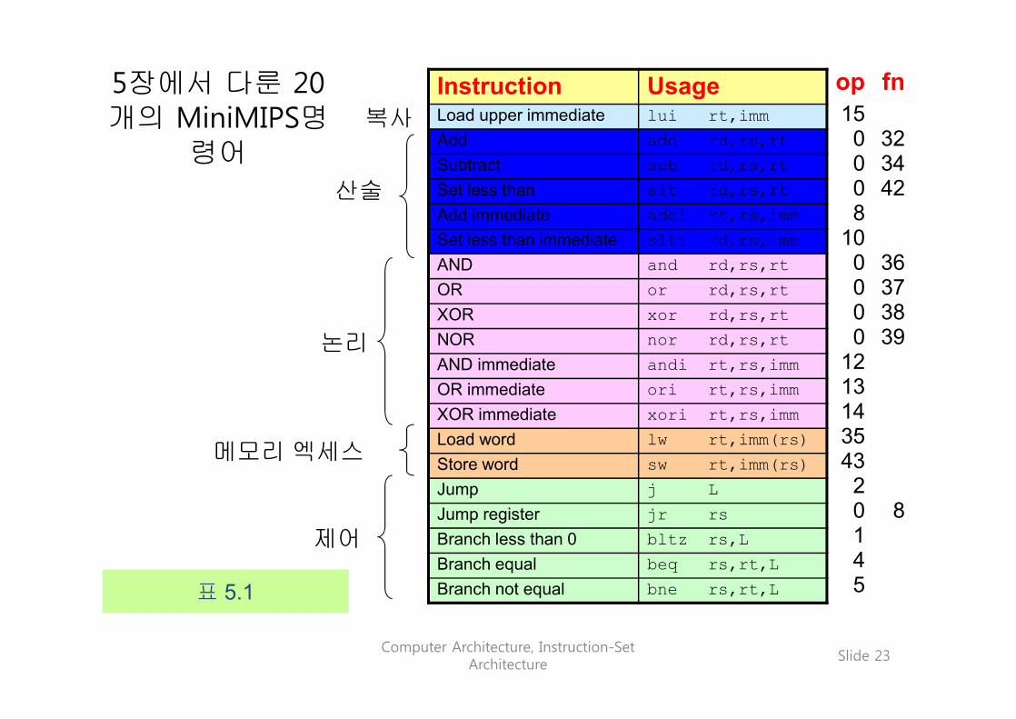
5장에서 다룬 20개의 MiniMIPS명
령어
Instruction UsageLoad upper immediate lui rt,immAdd add rd,rs,rtSubtract sub rd,rs,rtSet less than slt rd,rs,rtAdd immediate addi rt,rs,immSet less than immediate slti rd,rs,immAND and rd,rs,rtOR or rd,rs,rtXOR xor rd,rs,rtNOR nor rd,rs,rtAND immediate andi rt,rs,immOR immediate ori rt,rs,immXOR immediate xori rt,rs,immLoad word lw rt,imm(rs)Store word sw rt,imm(rs)Jump j LJump register jr rsBranch less than 0 bltz rs,LBranch equal beq rs,rt,LBranch not equal bne rs,rt,L
복사
제어
논리
산술
메모리 엑세스
op150008
100000
121314354320145
fn
323442
36373839
8
표 5.1

Computer Architecture, Instruction-Set Architecture
Slide 24
6 프로시저와 데이터
Topics in This Chapter
6.1 간단한 프로시저 호출
6.2 데이터 저장을 위한 스택 사용
6.3 인수와 결과
6.4 데이터 유형
6.5 베열과 포인터
6.6 그 밖의 명령어
MiniMIPS의 명령어와 데이터 타입:• 프로시저 호출/복귀 및 기타 명령어• 프로시저 파라미터와 결과, 스택의 사용

Computer Architecture, Instruction-Set Architecture
Slide 25
6.1 간단한 프로시저 호출프로시저를 사용하는 경우 다음과 같은 일련의 동작이 일어난다.
1. 프로시저가 알고 있는 위치에 인수들을 넣어둔다.(reg’s $a0-$a3)
2. 복귀 주소를 저장하고 프로시저로 제어를 넘긴다.(jal)3. 필요하면 프로시저가 사용할 수 있는 저장 공간을 확보한다.4. 원하는 작업을 수행한다.5. 호출 프로그램이 알고 있는 위치에 결과들을 넣어둔다.(reg’s
$v0-$v1)6. 호출지점으로 제어를 복귀한다.(jr)
프로시저 호출 및 복귀와 관련된 MiniMIPS 명령어:
jal proc # jump to loc “proc” and link;# “link” means “save the return# address” (PC)+4 in $ra ($31)
jr rs # go to loc addressed by rs

Computer Architecture, Instruction-Set Architecture
Slide 26
프로시저 호출의 개념
Figure 6.1 메인 프로그램과 프로시저와의 관계.
jal proc
jr $ra
proc Save, etc.
Restore
PC Prepare
to continue
Prepare to call
main

Computer Architecture, Instruction-Set Architecture
Slide 27
Example 6.1 MiniMIPS 프로시저의 간단한 예
정수값의 절대치를 찾는 프로시저.
$v0 ¬ |($a0)|Solution
x 의 절대값은 x < 0이면 –x 아니면 x.
abs: sub $v0,$zero,$a0 # put -($a0) in $v0; # in case ($a0) < 0
bltz $a0,done # if ($a0)<0 then done add $v0,$a0,$zero # else put ($a0) in $v0
done: jr $ra # return to calling program실제로 이와 같은 짧은 프로시저는 수반되는 오버헤드 때문에 자주 사
용하지는 않는다. 이 예에서 실제로는 3개의 명령어만 있으면 되지만 3-4개의 오버헤드가 생긴다.
Computer Architecture, Instruction-Set Architecture
Slide 28
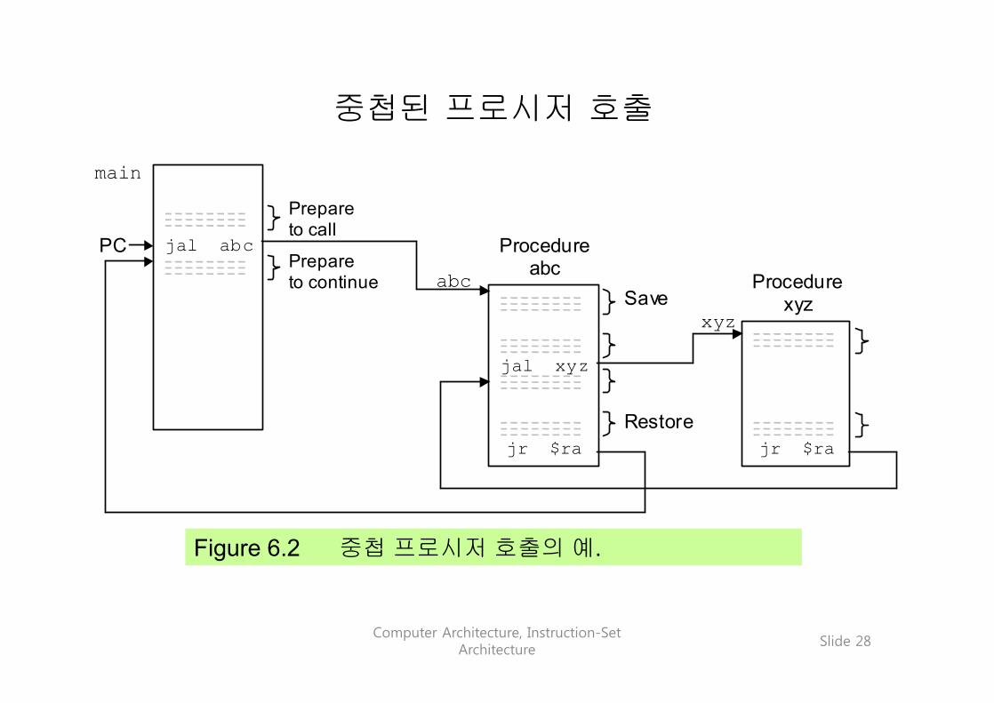
중첩된 프로시저 호출
Figure 6.2 중첩 프로시저 호출의 예.
jal abc
jr $ra
abc Save
Restore
PC Prepare to continue
Prepare to call
main
jal xyz
jr $ra
xyz
Procedure abc
Procedure xyz

Computer Architecture, Instruction-Set Architecture
Slide 29
6.2 데이터 저장을 위한 스택의 사용
Figure 6.4 스택에서의 Push와 Pop동작의 효과.
b a
sp
b a
sp b a sp
c
Push c Pop x
sp = sp – 4 mem[sp] = c
x = mem[sp] sp = sp + 4
push: addi $sp,$sp,-4sw $t4,0($sp)
pop: lw $t5,0($sp)addi $sp,$sp,4
Computer Architecture, Instruction-Set Architecture
Slide 30
Memory Map in
MiniMIPS
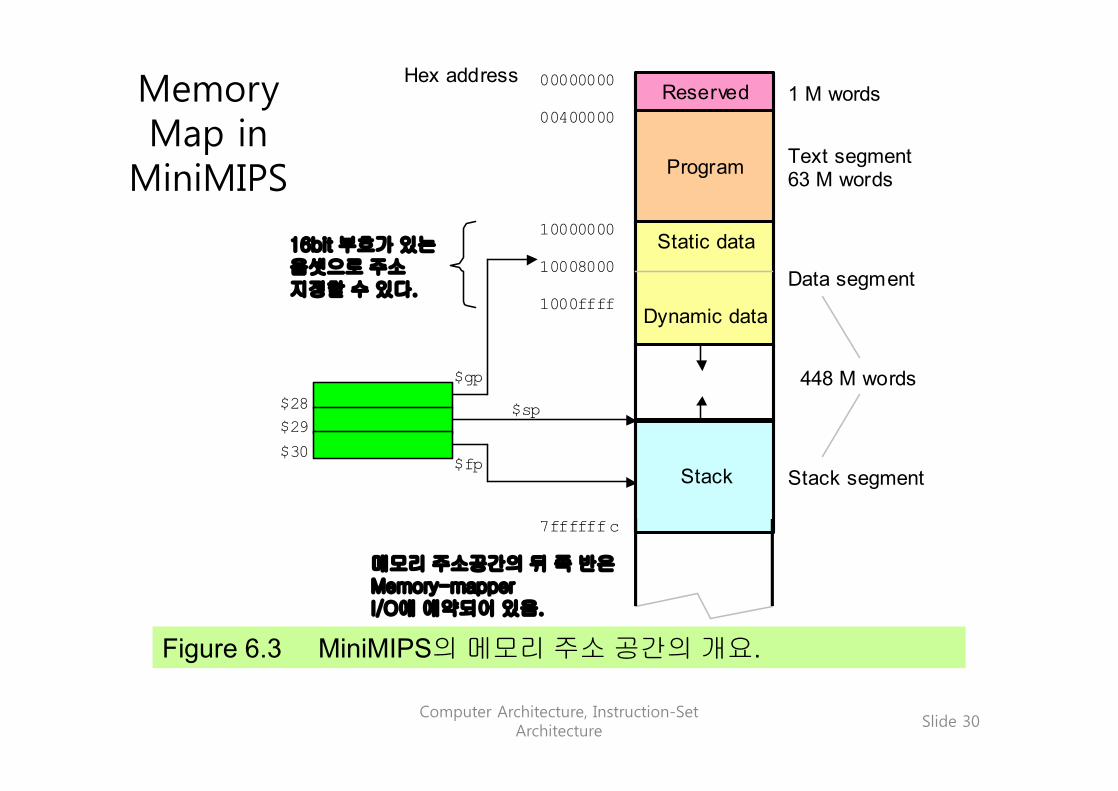
Figure 6.3 MiniMIPS의 메모리 주소 공간의 개요.
Reserved
Program
Stack
1 M words
Hex address
10008000
1000ffff
10000000
00000000
00400000
7ffffffc
Text segment 63 M words
Data segment
Stack segment
Static data
Dynamic data $gp
$sp
$fp
448 M words
Second half of address space reserved for memory-mapped I/O
$28 $29 $30
Addressable with 16-bit signed offset
메모리 주소공간의 뒤 쪽 반은Memory-mapperI/O에 예약되어 있음.
16bit 부호가 있는옵셋으로 주소지정할 수 있다.

Computer Architecture, Instruction-Set Architecture
Slide 31
6.3 인수와 결과
Figure 6.5 프로시저에 의한 스택 사용.
b a
$sp c Frame for current procedure
$fp . . .
Before calling
b a
$sp
c Frame for previous procedure
$fp
. . .
After calling
Frame for current procedure
Old ($fp)
Saved registers
y z
. . . Local variables
스택은 여러 개의 값을 전달하거나 반환 받을 수 있게 한다.
현재프로시저에대한 프레임
이전프로시저에대한 프레임
지역변수
레지스터저장
현재프로시저에대한 프레임
호출하기 전 호출한 후

Computer Architecture, Instruction-Set Architecture
Slide 32
스택의 사용 예
proc: sw $fp,-4($sp) # save the old frame pointeraddi $fp,$sp,0 # save ($sp) into $fpaddi $sp,$sp,–12 # create 3 spaces on top of stacksw $ra,-8($fp) # save ($ra) in 2nd stack elementsw $s0,-12($fp) # save ($s0) in top stack element...lw $s0,-12($fp) # put top stack element in $s0lw $ra,-8($fp) # put 2nd stack element in $raaddi $sp,$fp, 0 # restore $sp to original statelw $fp,-4($sp) # restore $fp to original statejr $ra # return from procedure
스택에 $fp, $ra, 및 $s0를 저장하고, 프로시저가 끝날 때 이들을 다시 환원한다.
Computer Architecture, Instruction-Set Architecture
Slide 33
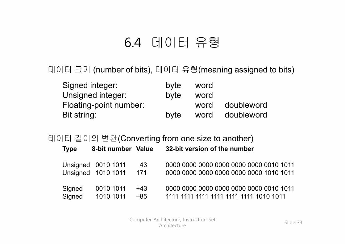
6.4 데이터 유형
데이터 크기 (number of bits), 데이터 유형(meaning assigned to bits)
Signed integer: byte wordUnsigned integer: byte wordFloating-point number: word doublewordBit string: byte word doubleword
테이터 길이의 변환(Converting from one size to another)Type 8-bit number Value 32-bit version of the number
Unsigned 0010 1011 43 0000 0000 0000 0000 0000 0000 0010 1011Unsigned 1010 1011 171 0000 0000 0000 0000 0000 0000 1010 1011
Signed 0010 1011 +43 0000 0000 0000 0000 0000 0000 0010 1011Signed 1010 1011 –85 1111 1111 1111 1111 1111 1111 1010 1011

Computer Architecture, Instruction-Set Architecture
Slide 34
ASCII CharactersTable 6.1 ASCII (American standard code for information interchange)
NUL DLE SP 0 @ P ` pSOH DC1 ! 1 A Q a qSTX DC2 “ 2 B R b rETX DC3 # 3 C S c sEOT DC4 $ 4 D T d tENQ NAK % 5 E U e uACK SYN & 6 F V f vBEL ETB ‘ 7 G W g wBS CAN ( 8 H X h xHT EM ) 9 I Y i yLF SUB * : J Z j zVT ESC + ; K [ k {FF FS , < L \ l |CR GS - = M ] m }SO RS . > N ^ n ~SI US / ? O _ o DEL
0123456789abcdef
0 1 2 3 4 5 6 7 8-9 a-f
Morecontrols
Moresymbols
8-bit ASCII code(col #, row #)hex
e.g., code for + is (2b) hex or(0010 1011)two

Computer Architecture, Instruction-Set Architecture
Slide 35
바이트들의 적재와 저장
Figure 6.6 바이트 크기의 데이터 요소를 위한 적재 및 저장 명령어.
x x 0 0 0 0 0 0 0 0 0 0 0 0 0 1 0 0 1 0 0 0 0 0 0 31 25 20 15 0
lb = 32 lbu = 36 sb = 40
Data register
Base register
Address offset
op rs rt immediate / offset
I 1 1 0 0 0 1 1
바이트는 ASCII문자나 작은 정수를 저장하는 데 사용할 수 있다. MiniMIPS의 주소에는 바이트를 저장하지만 레지스터는 워드를 저장한다.
lb $t0,8($s3) # load rt with mem[8+($s3)]# sign-extend to fill reg
lbu $t0,8($s3) # load rt with mem[8+($s3)]# zero-extend to fill reg
sb $t0,A($s3) # LSB of rt to mem[A+($s3)]

Computer Architecture, Instruction-Set Architecture
Slide 36
메모리에서 워드의 의미
Figure 6.7 32-bit word는 고유의 의미를 갖고 있지 않으며, 의도하는 의미를 위한 다른 단서(예, 문맥)가 없을 때는 여러 유효한방법 중의 하나로 해석될 수 있다.
0000 0010 0001 0001 0100 0000 0010 0000
Positive integer
Four-character string
Add instruction
Bit pattern (02114020) hex
00000010000100010100000000100000
00000010000100010100000000100000
00000010000100010100000000100000

Computer Architecture, Instruction-Set Architecture
Slide 37
6.5 배열과 포인터Index: 레지스터는 인덱스 i를 가지고 있고, 매 단계마다 레지스터를 증가시켜 리스트의 i번째 요소에서 i + 1 번째 요소로 이동하는 효과를 낸다.
Pointer: 레지스터에는 리스트 요소의 포인트(즉, 주소)를 저장하여 이를 가지고 검사하며, 매 단계마다 다음 요소의 포인터를 갱신한다.
Add 4 to get the address of A[i + 1]
Pointer to A[i] Array index i
Add 1 to i; Compute 4i; Add 4i to base
A[i] A[i + 1]
A[i] A[i + 1]
Base Array A Array A
Figure 6.8 배열 요소를 거쳐가는 단계를 위한 색인 방법 및 포인터갱신 방법의 사용.

Computer Architecture, Instruction-Set Architecture
Slide 38
선택 정렬
Example 6.4
Figure 6.9 선택 정렬의 1회 반복.
first
last
max
first
last
first
last
Start of iteration Maximum identified End of iteration
x
x y
y
A A A
일련의 수들을 정렬하려면 다음 과정을 반복실행한다:최댓값을 찾고, 마지막 요소와 교환하고, “last” 포인터를 위로 이동한다.

Computer Architecture, Instruction-Set Architecture
Slide 39
max 프로시저를 이용한 선택 정렬Example 6.4 (continued)
sort: beq $a0,$a1,done # single-element list is sortedjal max # call the max procedurelw $t0,0($a1) # load last element into $t0sw $t0,0($v0) # copy the last element to max locsw $v1,0($a1) # copy max value to last elementaddi $a1,$a1,-4 # decrement pointer to last elementj sort # repeat sort for smaller list
done: ... # continue with rest of program
first
last
max
first
last
first
last
Start of iteration Maximum identified End of iteration
x
x y
y
A A A
Inputs toproc max
Outputs fromproc max
In $a0
In $a1In $v0 In $v1

Computer Architecture, Instruction-Set Architecture
Slide 40
6.6 그 밖의 명령어들
Figure 6.10 MiniMIPS 의 곱셈 (mult)과 나눗셈(div) 명령
1 0 0 1 1 0 0
fn
0 0 0 0 0 0 0 0 0 0 0 0 x 0 0 1 1 0 0 0 0 0 0 0 0 31 25 20 15 0
ALU instruction
Source register 1
Source register 2
op rs rt
R rd sh
10 5
Unused Unused mult = 24 div = 26
1 0 0 0 0 0 0 1 0 0
fn
0 0 0 0 0 0 0 0 0 0 0 x 0 0 0 0 0 0 0 0 0 0 31 25 20 15 0
ALU instruction
Unused Unused
op rs rt
R rd sh
10 5
Destination register
Unused mfhi = 16 mflo = 18
Figure 6.11 Hi와 Lo 레지스터의 내용을 일반 레지스터에 복사하는 MiniMIPS 명령
곱셈과 나눗셈 MiniMIPS 명령어 :
mult $s0, $s1 # set Hi,Lo to ($s0)´($s1)div $s0, $s1 # set Hi to ($s0)mod($s1)
# and Lo to ($s0)/($s1)mfhi $t0 # set $t0 to (Hi)mflo $t0 # set $t0 to (Lo)

Computer Architecture, Instruction-Set Architecture
Slide 41
Logical Shifts
Figure 6.12 MiniMIPS의 4가지 논리 shift 명령어.
좌측 및 우측 shift연산의 MiniMIPS 명령어:
sll $t0,$s1,2 # $t0=($s1) left-shifted by 2srl $t0,$s1,2 # $t0=($s1) right-shifted by 2sllv $t0,$s1,$s0 # $t0=($s1) left-shifted by ($s0)srlv $t0,$s1,$s0 # $t0=($s1) right-shifted by ($s0)
0
x
0 0
fn
0 0 0 0 0 0 0 0 0 0 0 1 0 0 x 0 0 1 1 1 0 0 0 0 0 0 0 0 0 31 25 20 15 0
ALU instruction
Unused Source register
op rs rt
R rd sh
10 5
Destination register
Shift amount
sll = 0 srl = 2
1 0 0 0 0 0 0 0 0 0 0 0 0 0 0 0 0 0 1 1 1 1 0 0 0 0 0 0 0 0 0 31 25 20 15 0
ALU instruction
Amount register
Source register
op rs rt
R rd sh
10 5 fn
Destination register
Unused sllv = 4 srlv = 6

Computer Architecture, Instruction-Set Architecture
Slide 42
양수의 산술 연산과 기타 명령어
MiniMIPS의 양수 산술연산 명령(오버플로 예외 없음) :
addu $t0,$s0,$s1 # set $t0 to ($s0)+($s1)subu $t0,$s0,$s1 # set $t0 to ($s0)–($s1)multu $s0,$s1 # set Hi,Lo to ($s0)´($s1)divu $s0,$s1 # set Hi to ($s0)mod($s1)
# and Lo to ($s0)/($s1)addiu $t0,$s0,61 # set $t0 to ($s0)+61;
# the immediate operand is# sign extended
MiniMIPS를 더 강력하고 완전하게 만드는 명령, 뒤에서 소개할 것임:
sra $t0,$s1,2 # sh. right arith (Sec. 10.5)srav $t0,$s1,$s0 # shift right arith variablesyscall # system call (Sec. 7.6)

Computer Architecture, Instruction-Set Architecture
Slide 43
The 20 MiniMIPS Instructions
from Chapter 6(40 in all so far)
Instruction UsageMove from Hi mfhi rdMove from Lo mflo rdAdd unsigned addu rd,rs,rtSubtract unsigned subu rd,rs,rtMultiply mult rs,rtMultiply unsigned multu rs,rtDivide div rs,rtDivide unsigned divu rs,rtAdd immediate unsigned addiu rs,rt,immShift left logical sll rd,rt,shShift right logical srl rd,rt,shShift right arithmetic sra rd,rt,shShift left logical variable sllv rd,rt,rsShift right logical variable srlv rt,rd,rsShift right arith variable srav rd,rt,rdLoad byte lb rt,imm(rs)Load byte unsigned lbu rt,imm(rs)Store byte sb rt,imm(rs)Jump and link jal LSystem call syscall
Copy
Control transfer
Shift
Arithmetic
Memory access
op000000009000000
32364030
fn1618333524252627
023467
12
Table 6.2 (partial)
Computer Architecture, Instruction-Set Architecture
Slide 44
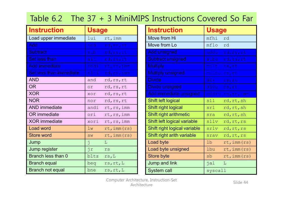
Table 6.2 The 37 + 3 MiniMIPS Instructions Covered So FarInstruction UsageMove from Hi mfhi rdMove from Lo mflo rdAdd unsigned addu rd,rs,rtSubtract unsigned subu rd,rs,rtMultiply mult rs,rtMultiply unsigned multu rs,rtDivide div rs,rtDivide unsigned divu rs,rtAdd immediate unsigned addiu rs,rt,immShift left logical sll rd,rt,shShift right logical srl rd,rt,shShift right arithmetic sra rd,rt,shShift left logical variable sllv rd,rt,rsShift right logical variable srlv rd,rt,rsShift right arith variable srav rd,rt,rsLoad byte lb rt,imm(rs)Load byte unsigned lbu rt,imm(rs)Store byte sb rt,imm(rs)Jump and link jal LSystem call syscall
Instruction UsageLoad upper immediate lui rt,immAdd add rd,rs,rtSubtract sub rd,rs,rtSet less than slt rd,rs,rtAdd immediate addi rt,rs,immSet less than immediate slti rd,rs,immAND and rd,rs,rtOR or rd,rs,rtXOR xor rd,rs,rtNOR nor rd,rs,rtAND immediate andi rt,rs,immOR immediate ori rt,rs,immXOR immediate xori rt,rs,immLoad word lw rt,imm(rs)Store word sw rt,imm(rs)Jump j LJump register jr rsBranch less than 0 bltz rs,LBranch equal beq rs,rt,LBranch not equal bne rs,rt,L
Computer Architecture, Instruction-Set Architecture
Slide 45
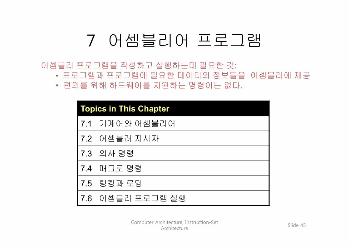
7 어셈블리어 프로그램
Topics in This Chapter
7.1 기계어와 어셈블리어
7.2 어셈블러 지시자
7.3 의사 명령
7.4 매크로 명령
7.5 링킹과 로딩
7.6 어셈블러 프로그램 실행
어셈블리 프로그램을 작성하고 실행하는데 필요한 것:• 프로그램과 프로그램에 필요한 데이터의 정보들을 어셈블러에 제공• 편의를 위해 하드웨어를 지원하는 명령어는 없다.

Computer Architecture, Instruction-Set Architecture
Slide 46
7.1 기계어와 어셈블러
Figure 7.1 어셈블리어 프로그램이 메모리에서 실행될 수 있는 프로그램으로 변환되는 과정
Link
er
Load
er
Ass
embl
er
add $2,$5,$5 add $2,$2,$2 add $2,$4,$2 lw $15,0($2) lw $16,4($2) sw $16,0($2) sw $15,4($2) jr $31
00a51020 00421020 00821020 8c620000 8cf20004 acf20000 ac620004 03e00008
Assembly language program
Machine language program
Executable machine language program
Memory content
Library routines (machine language) MIPS, 80x86,
PowerPC, etc.

Computer Architecture, Instruction-Set Architecture
Slide 47
Symbol Table
Figure 7.2 어셈블리어 프로그램, 그에 해당하는 기계어 프로그램, 어셈블이 과정에서 생성된 심벌 테이블
0 00100000000100000000000000001001
addi $s0,$zero,9
test
done result
12
28 248
4 00000010000100000100000000100010 8 00000001001000000000000000100000 12 00010101000100000000000000001100 16 00100001000010000000000000000001 20 00000010000000000100100000100000 24 00001000000000000000000000000011 28 10101111100010010000000011111000
Determined from assembler directives not shown here
Symbol table
done: sw $t1,result($gp)
sub $t0,$s0,$s0 add $t1,$zero,$zero test: bne $t0,$s0,done addi $t0,$t0,1 add $t1,$s0,$zero j test
Assembly language program Machine language program Location
op rs rt rd sh fn Field boundaries shown to facilitate understanding 이해를 돕기 위해 필드의 경계를 표시했다.
어셈블러 지시자로 부터 결정되며,여기서는 보여주지 않음.
Computer Architecture, Instruction-Set Architecture
Slide 48
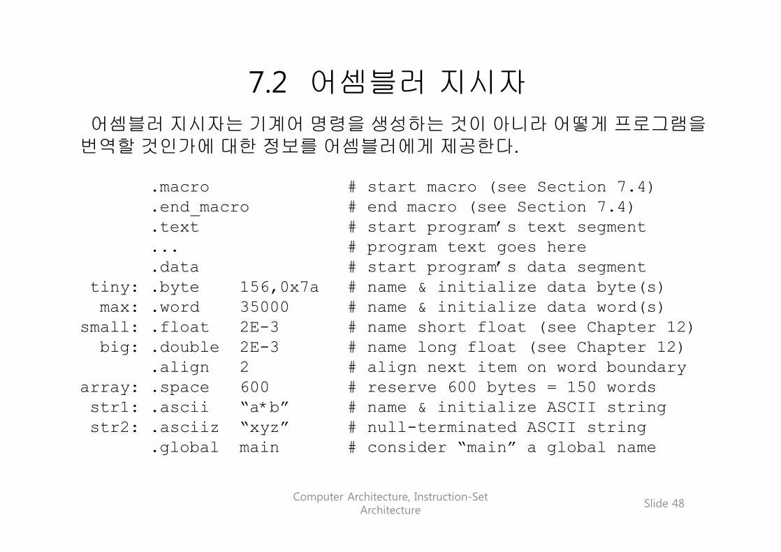
7.2 어셈블러 지시자
어셈블러 지시자는 기계어 명령을 생성하는 것이 아니라 어떻게 프로그램을번역할 것인가에 대한 정보를 어셈블러에게 제공한다.
.macro # start macro (see Section 7.4)
.end_macro # end macro (see Section 7.4)
.text # start program’s text segment
... # program text goes here
.data # start program’s data segmenttiny: .byte 156,0x7a # name & initialize data byte(s)max: .word 35000 # name & initialize data word(s)
small: .float 2E-3 # name short float (see Chapter 12)big: .double 2E-3 # name long float (see Chapter 12)
.align 2 # align next item on word boundaryarray: .space 600 # reserve 600 bytes = 150 wordsstr1: .ascii “a*b” # name & initialize ASCII string str2: .asciiz “xyz” # null-terminated ASCII string
.global main # consider “main” a global name

Computer Architecture, Instruction-Set Architecture
Slide 49
간단한 어셈블러 지시자의 구성
다음과 같은 각각의 기능을 갖는 어셈블러 지시자를 써라:
a. 메모리에 에러 메시지 “Warning: The printer is out of paper!” 을 저장하라.b. 값이 4인 “size” 라는 상수를 설정하라.c. 초기값이 4인 “width” 라는 정수 변수를 설정하라.d. 값이 1,000,000인 “mill”이라는 상수를 설정하라..e. 길이가 250인 정수 벡터 “vect” 의 공간을 확보하라.
Solution:
a. noppr: .asciiz “Warning: The printer is out of paper!”b. size: .byte 4 # small constant fits in one bytec. width: .word 4 # byte could be enough, but ...d. mill: .word 1000000 # constant too large for bytee. vect: .space 1000 # 250 words = 1000 bytes
Example 7.1

Computer Architecture, Instruction-Set Architecture
Slide 50
7.3 의사명령
1 대 1 의사 명령의 예: 다음 명령
not $s0 # complement ($s0)은 다음과 같은 실제 명령으로 변환된다:
nor $s0,$s0,$zero # complement ($s0)
1 대 다 의사명령의 예: 다음 명령
abs $t0,$s0 # put |($s0)| into $t0은 다음과 같이 여러 개의 명령으로 변환된다:
add $t0,$s0,$zero # copy x into $t0slt $at,$t0,$zero # is x negative?beq $at,$zero,+4 # if not, skip next instrsub $t0,$zero,$s0 # the result is 0 – x

Computer Architecture, Instruction-Set Architecture
Slide 51
MiniMIPS Pseudo-
instructions
Pseudoinstruction UsageMove move regd,regsLoad address la regd,addressLoad immediate li regd,anyimmAbsolute value abs regd,regsNegate neg regd,regsMultiply (into register) mul regd,reg1,reg2Divide (into register) div regd,reg1,reg2Remainder rem regd,reg1,reg2Set greater than sgt regd,reg1,reg2Set less or equal sle regd,reg1,reg2Set greater or equal sge regd,reg1,reg2Rotate left rol regd,reg1,reg2Rotate right ror regd,reg1,reg2NOT not regLoad doubleword ld regd,addressStore doubleword sd regd,addressBranch less than blt reg1,reg2,LBranch greater than bgt reg1,reg2,LBranch less or equal ble reg1,reg2,LBranch greater or equal bge reg1,reg2,L
복사
제어 전송명령
시프트
산술명령
메모리 엑세스
Table 7.1
논리

Computer Architecture, Instruction-Set Architecture
Slide 52
7.4 매크로 명령
메크로는 자주 사용되는 일련의 명령어 들에 이름을 부여하여사용하는 메커니즘이다. (shorthand notation)
.macro name(args) # macro and arguments named
... # instr’s defining the macro
.end_macro # macro terminator
매크로와 의사명령과의 차이점은?의사명령: 사전 정의된 명령(predefined), 고정되어 있고,
기계어처럼 보인다.매크로 : 사용자 정의이며, 프로시저와 유사하다.(have arguments)
매크로와 프로시저와의 차이점은?프로시저는 제어를 넘겨받은 뒤 다시 반환한다.매크로는 치환되어 사용되며, 이후에는 흔적이 남지 않음.
Computer Architecture, Instruction-Set Architecture
Slide 53
7.5 링킹과 로딩
링커는 다음과 같은 기능을 갖는다:각 모듈에 있는 레이블(label)들의 정확한 변환을 보장한다.메모리의 텍스트와 데이터 세그먼트의 배치를 결정한다.모든 데이터의 주소와 명령 레이블을 검사한다(evaluating).모든 참조(reference)가 해결된 실행가능한 형태로 프로그램을 구성
로더의 기능은 다음과 같다:프로그램의 시작부분에서 필요한 메모리를 결정한다.실행가능한 프로그램 파일로 부터 텍스트와 데이터를 메모리로 복사복사하는 과정에서 필요하다면 주소들을 수정(시프팅)한다.프로그램의 매개변수들을 스택에 저장한다(프로시저 호출에서 처럼)스택 포인터를 포함한 모든 레지스터들을 초기화한다.일명 프로그램의 메인 루틴이라는 시작점으로 점프한다.
Computer Architecture, Instruction-Set Architecture
Slide 54
7.6 어셈블러 프로그램 실행
Spim은 MiniMIPS 프로그램을 실행할 수 있는 시뮬레이터이다.
Spim이란 이름은 MIPS을 거꾸로 쓴 것이다.
세가지 버전의 Spim을 무료로 사용할 수 있다:
PCSpim for Windows machinesxspim for X-windowsspim for Unix systems
SPIM은 다음 사이트에서 다운로드 할 수 있다:
http://www.cs.wisc.edu/~larus/spim.html
Computer Architecture, Instruction-Set Architecture
Slide 55
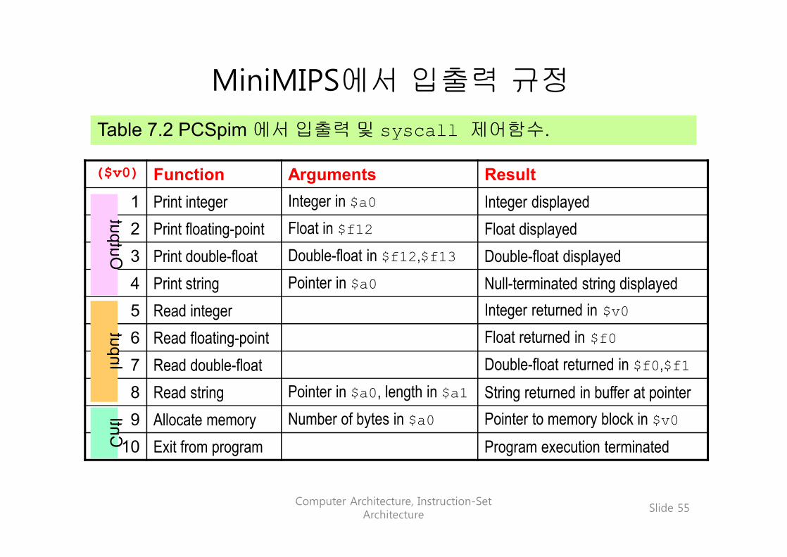
MiniMIPS에서 입출력 규정
Table 7.2 PCSpim 에서 입출력 및 syscall 제어함수.
($v0) Function Arguments Result1 Print integer Integer in $a0 Integer displayed2 Print floating-point Float in $f12 Float displayed3 Print double-float Double-float in $f12,$f13 Double-float displayed4 Print string Pointer in $a0 Null-terminated string displayed5 Read integer Integer returned in $v06 Read floating-point Float returned in $f07 Read double-float Double-float returned in $f0,$f18 Read string Pointer in $a0, length in $a1 String returned in buffer at pointer9 Allocate memory Number of bytes in $a0 Pointer to memory block in $v0
10 Exit from program Program execution terminated
Output
Input
Cntl
Computer Architecture, Instruction-Set Architecture
Slide 56
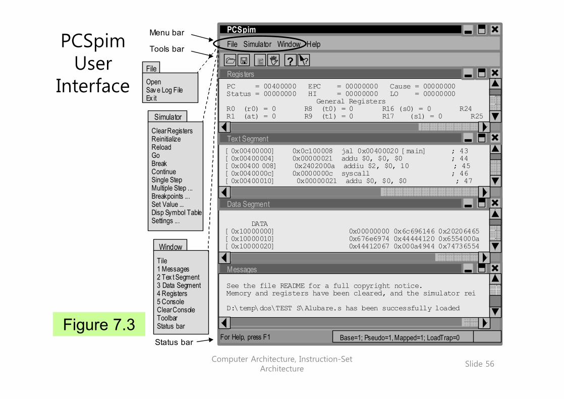
Figure 7.3
PCSpim User
Interface
Status bar
Menu bar Tools bar
File
Simulator
Window
Open Sav e Log File Ex it
Tile 1 Messages 2 Tex t Segment 3 Data Segment 4 Registers 5 Console Clear Console Toolbar Status bar
Clear Registers Reinitialize Reload Go Break Continue Single Step Multiple Step ... Breakpoints ... Set Value ... Disp Symbol Table Settings ...
For Help, press F1
PCSpim
Regis ters
File Simulator Window Help
PC = 00400000 EPC = 00000000 Cause = 00000000 Status = 00000000 HI = 00000000 LO = 00000000 General Registers R0 (r0) = 0 R8 (t0) = 0 R16 (s0) = 0 R24 R1 (at) = 0 R9 (t1) = 0 R17 (s1) = 0 R25
[0x00400000] 0x0c100008 jal 0x00400020 [main] ; 43 [0x00400004] 0x00000021 addu $0, $0, $0 ; 44 [0x00400 008] 0x2402000a addiu $2, $0, 10 ; 45 [0x0040000c] 0x0000000c syscall ; 46 [0x00400010] 0x00000021 addu $0, $0, $0 ; 47
DATA [0x10000000] 0x00000000 0x6c696146 0x20206465 [0x10000010] 0x676e6974 0x44444120 0x6554000a [0x10000020] 0x44412067 0x000a4944 0x74736554
Text Segment
Data Segment
Messages
Base=1; Pseudo=1, Mapped=1; LoadTrap=0
?
?
1 < � I
See the file README for a full copyright notice. Memory and registers have been cleared, and the simulator rei D:\temp\dos\TEST S\Alubare.s has been successfully loaded
Computer Architecture, Instruction-Set Architecture
Slide 57
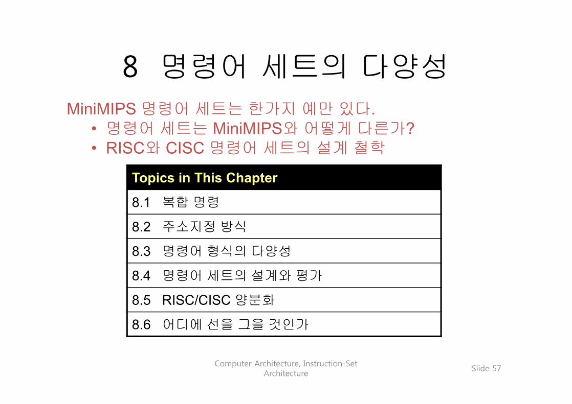
8 명령어 세트의 다양성
Topics in This Chapter
8.1 복합 명령
8.2 주소지정 방식
8.3 명령어 형식의 다양성
8.4 명령어 세트의 설계와 평가
8.5 RISC/CISC 양분화
8.6 어디에 선을 그을 것인가
MiniMIPS 명령어 세트는 한가지 예만 있다.• 명령어 세트는 MiniMIPS와 어떻게 다른가?• RISC와 CISC 명령어 세트의 설계 철학

Computer Architecture, Instruction-Set Architecture
Slide 58
8.1 복합 명령
Table 8.1 (partial) 대중적인 현대의 마이크로 프로세서 두 개와 역사적으로 중요한 컴퓨터 계열 두 가지의 복합 명령의 예.
Machine Instruction EffectPentium MOVS 두 개의 포인터 레지스터에 저장되어 있는 주소를 이용
하여 바이트, 워드 또는 더블워드 크기의 문자열의 내용을 하나씩 이동한다. 이 연산이 끝나면 문자열의 다음 내용을 가리키기 위하여 레지스터가 증가 또는 감소한다.
PowerPC cntlzd 지정된 소스 레지스터의 비트 위치 0에서 시작하여 연속된 0의 수를 세어 개수를 목적 레지스터에 저장한다.
IBM 360-370 CS 비교와 교환(compare and swap): 메모리 위치의 내용과 레지스터의 내용을 비교하여, 같지 않으면 메모리의내용을 레지스터로 읽어오고, 그렇지 않으면 다른 레지스터의 내용을 그 메모리 위치에 저장한다.
Digital VAX POLYD 복수 정밀도 부동소수점 산술연산에서, 명령 내에 주어진 메모리 위치의 계수 표를 참고하여. x의 다항식을 평가하며 그 결과를 높은 정밀도로 나타낸다.
Computer Architecture, Instruction-Set Architecture
Slide 59
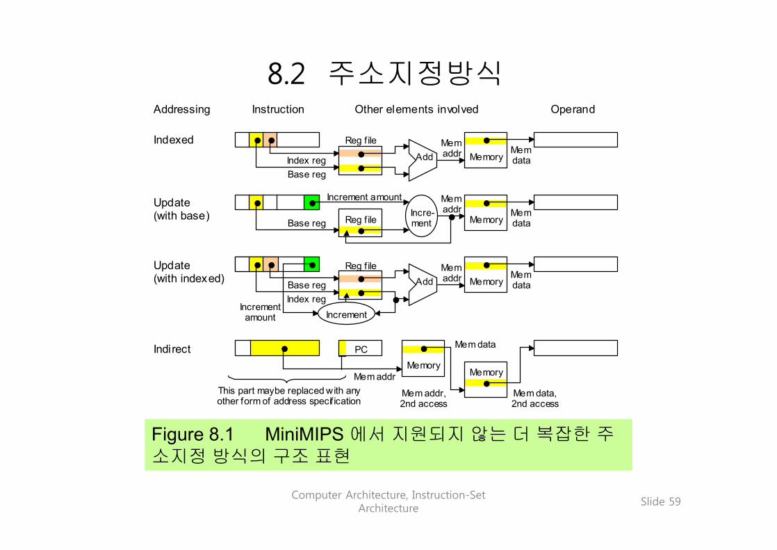
8.2 주소지정방식
Figure 8.1 MiniMIPS 에서 지원되지 않는 더 복잡한 주소지정 방식의 구조 표현
Addressing Instruction Other elements involved Operand
Mem data PC
Mem addr Memory
Memory Add
Reg f ile Mem addr Mem
data Index reg Base reg
Memory Reg f ile
Mem addr Mem
data
Increment amount
Base reg
Indirect
Indexed
Update (with base)
Update (with indexed) Memory Add
Reg f ile Mem addr Mem
data Index reg Base reg
Increment amount
Memory
Mem addr, 2nd access
Mem data, 2nd access
This part maybe replaced with any other form of address specif ication
Incre-ment
Increment

Computer Architecture, Instruction-Set Architecture
Slide 60
8.3 명령어 형식의 다양성
Figure 8.2 0~3개의 주소로 된 MiniMIPS 명령의 예. 색칠된부분은 사용되지 않는 부분이다.
3-address
0-address
1-address
2-address
syscall
j
mult
add
One implied operand in register $v0
Destination and two source registers addressed
Two source registers addressed, destination implied
Jump target addressed (in pseudodirect form)
Category Format Opcode Description of operand(s)
Address 2
12
rt rs 0 24
rt rs 0 rd 32
0
0-, 1-, 2-, and 3-address instructions
레지스터 $v0에 한 개의 묵시적 오퍼랜드가 있다.
목적지 주소로 점프(의사직접명령 형식에서)
두 개의 소스레지스터, 목적지는 묵시적
목적지와 두 개의 소스 레지스터

Computer Architecture, Instruction-Set Architecture
Slide 61
IA-32 (80x86) 명령의 가변 길이 형식의 구성
복합 명령 형식의 예
Offset or displacement (0, 1, 2, or 4 B)
Immediate (0, 1, 2, or 4 B)
Opcode (1-2 B)
Instruction prefixes (zero to four, 1 B each)
Mod Reg/Op R/M Scale Index Base
ModR/M SIB
오퍼랜드의 크기와주소의 크기를겸용으로 사용하고,다른 변경자를 지정
Most memoryoperands needthese 2 bytes
대부분의 오퍼랜드는이들 두 바이트가필요하다.
Computer Architecture, Instruction-Set Architecture
Slide 62
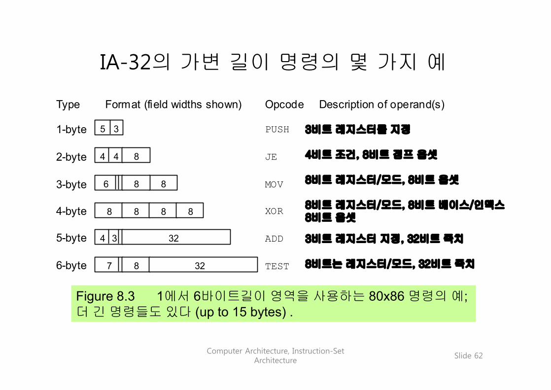
Figure 8.3 1에서 6바이트길이 영역을 사용하는 80x86 명령의 예; 더 긴 명령들도 있다 (up to 15 bytes) .
IA-32의 가변 길이 명령의 몇 가지 예
4-byte
1-byte
2-byte
3-byte
6-byte
5-byte
Type Format (field widths shown) Opcode Description of operand(s)
8 8 6
PUSH
JE
MOV
XOR
3-bit register specification
8-bit register/mode, 8-bit base/index, 8-bit offset
8-bit register/mode, 8-bit offset
4-bit condition, 8-bit jump offset
ADD
TEST 8-bit register/mode, 32-bit immediate
3-bit register spec, 32-bit immediate
5 3
4 4 8
3 32 4
7 8 32
8 8 8 8
3비트 레지스터를 지정
4비트 조건, 8비트 점프 옵셋
8비트 레지스터/모드, 8비트 옵셋
8비트 레지스터/모드, 8비트 베이스/인덱스8비트 옵셋
3비트 레지스터 지정, 32비트 즉치
8비트는 레지스터/모드, 32비트 즉치
Computer Architecture, Instruction-Set Architecture
Slide 63
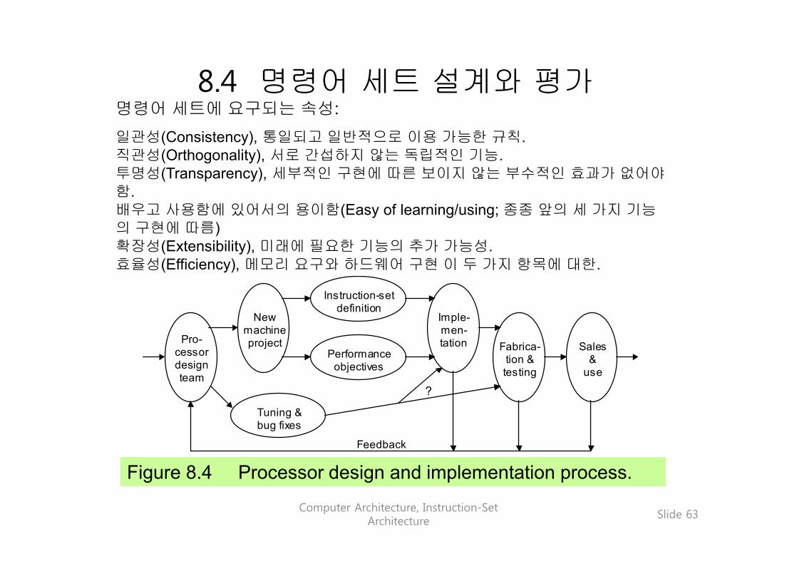
8.4 명령어 세트 설계와 평가
Figure 8.4 Processor design and implementation process.
Pro- cessor design team
New machine project
Tuning & bug fixes
Performance objectives
Instruction-set definition
Imple- men- tation Fabrica-
tion & testing
Sales &
use
?
Feedback
명령어 세트에 요구되는 속성:일관성(Consistency), 통일되고 일반적으로 이용 가능한 규칙.직관성(Orthogonality), 서로 간섭하지 않는 독립적인 기능.투명성(Transparency), 세부적인 구현에 따른 보이지 않는 부수적인 효과가 없어야함.배우고 사용함에 있어서의 용이함(Easy of learning/using; 종종 앞의 세 가지 기능의 구현에 따름)확장성(Extensibility), 미래에 필요한 기능의 추가 가능성.효율성(Efficiency), 메모리 요구와 하드웨어 구현 이 두 가지 항목에 대한.

Computer Architecture, Instruction-Set Architecture
Slide 64
8.5 RISC/CISC 양분화
RISC (reduced instruction set computer) 철학:명령코드와 오퍼랜드의 모든 조합 가능성을 해독하는 메커니즘은결과적으로 명령 세트를 매우 복잡하게 만듦으로 아주 단순한 동작조차도 속도를 떨어지게 만들었다.
RISC 구조의 특징
1. 작은 명령 세트, 각 명령어는 대략적으로 다음을 실행할 수 있어야 한다.
2. 적재/저장(Load/store) 구조 (많은 레지스터가 필요함)3. 주소 계산을 단순하게 하기 위한 제한된 주소지정 방식4. 단순하고 통일된 명령형식 (해독의 용이성)
필요할 때마다 임기응변식으로 명령어 집합을 확장하면 점점 더복잡하게 되어 결과적으로 CISC가 된다; 현대의 영어는 여러 세대를거치면서 사용된 모든 영어를 다 포함하고 있다는 것을 생각해 보라.
Computer Architecture, Instruction-Set Architecture
Slide 65
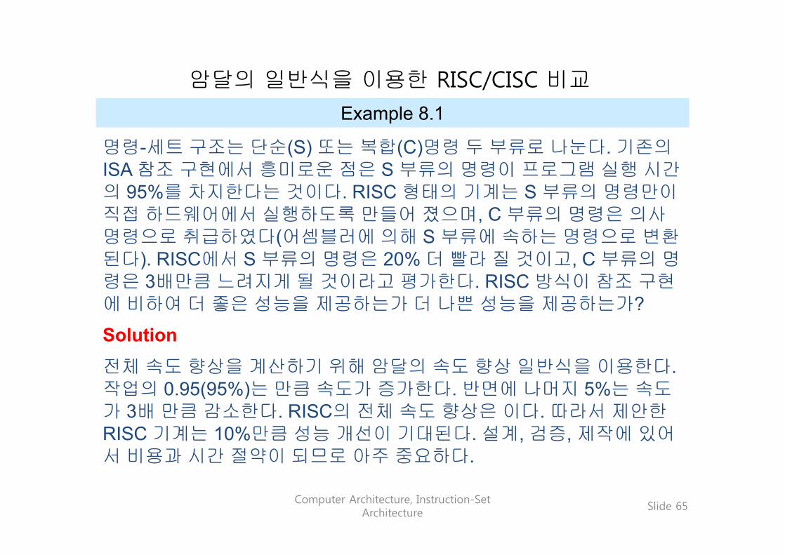
암달의 일반식을 이용한 RISC/CISC 비교
Example 8.1
명령-세트 구조는 단순(S) 또는 복합(C)명령 두 부류로 나눈다. 기존의ISA 참조 구현에서 흥미로운 점은 S 부류의 명령이 프로그램 실행 시간의 95%를 차지한다는 것이다. RISC 형태의 기계는 S 부류의 명령만이직접 하드웨어에서 실행하도록 만들어 졌으며, C 부류의 명령은 의사명령으로 취급하였다(어셈블러에 의해 S 부류에 속하는 명령으로 변환된다). RISC에서 S 부류의 명령은 20% 더 빨라 질 것이고, C 부류의 명령은 3배만큼 느려지게 될 것이라고 평가한다. RISC 방식이 참조 구현에 비하여 더 좋은 성능을 제공하는가 더 나쁜 성능을 제공하는가?
Solution전체 속도 향상을 계산하기 위해 암달의 속도 향상 일반식을 이용한다. 작업의 0.95(95%)는 만큼 속도가 증가한다. 반면에 나머지 5%는 속도가 3배 만큼 감소한다. RISC의 전체 속도 향상은 이다. 따라서 제안한RISC 기계는 10%만큼 성능 개선이 기대된다. 설계, 검증, 제작에 있어서 비용과 시간 절약이 되므로 아주 중요하다.

Computer Architecture, Instruction-Set Architecture
Slide 66
8.6 어디에 경계선을 그을 것인가
The ultimate reduced instruction set computer (URISC):실질적인 계산에 필요한 명령의 절대적인 개수는 몇 개인가?
단 한 개!subtract operand1 from operand2, replace operand2 with result, and jump to target address if result is negative
어셈블리어 형식:
label: urisc dest,src1,target
의사명령어는 한 개의 명령을 사용하여 합성될 수 있다:
stop: .word 0start: urisc dest,dest,+1 # dest = 0
urisc src,dest,+1 # temp = -(src)urisc temp,dest,+1 # dest = -(temp)... # rest of program

Computer Architecture, Instruction-Set Architecture
Slide 67
Figure 8.5 URISC의 명령형식과 하드웨어 구조.
URISC Hardware
MAR
in
Memory unit
Adder
P C
Write
Read
Word 1
Source 1 Source 2 / Dest Jump target
Word 2 Word 3
URISC instruction:
R M A R
M D R
N Z
PC
in
PC
out
MDR
in
R
in
N in
Z in
C in
Comp
0 1 Mux
0
1
0
R’


![ESD.ppt [호환 모드] - CBNUbandi.cbnu.ac.kr/~ysk/ESD.pdf · Microsoft PowerPoint - ESD.ppt [호환 모드] Author: share Created Date: 9/28/2011 6:39:47 PM](https://img.pdfslide.net/doc/110x75/5f6761227d2eef5e8b4197f2/esdppt-eeoe-yskesdpdf-microsoft-powerpoint-esdppt-eeoe.jpg)