Embed Size (px)
Citation preview
REGULATIONS AND INSTRUCTIONS
PART III
WATER WELL MINIMUM
CONSTRUCTION STANDARDS
CHEYENNE, WYOMING
REVISED FEBRUARY 2010
TABLE OF CONTENTS
PART III
CHAPTER 1
PURPOSE
SECTION 1: Purpose and Scope 1-1
SECTION 2: Authority 1-2
CHAPTER 2
REQUIREMENTS AND DEFINITIONS
SECTION 1: Statutory Requirements 2-1
SECTION 2: Definitions 2-2
CHAPTER 3
WELL CONSTRUCTION
SECTION 1: Water Well Siting 3-1
SECTION 2: Water Well Construction 3-2
SECTION 3: Water Well Equipping 3-9
CHAPTER 4
WELL COMPLETION AND MAINTENANCE
SECTION 1: Disinfection 4-1
SECTION 2: Spring Developments 4-2
SECTION 3: Water Well Rehabilitation 4-2
SECTION 4: Water Well Plugging and Abandonment 4-3
SECTION 5: Water Quality 4-4
CHAPTER 5
APPENDICES
Appendix A: Disinfection Table A-1
Appendix B: Conversion Tables B-1
Appendix C-1: Type I Wells C-1
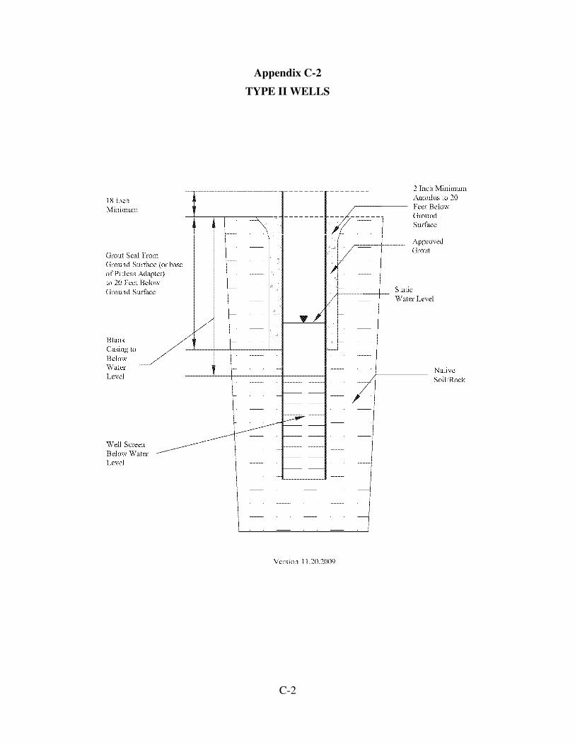
Appendix C-2: Type II Wells C-2
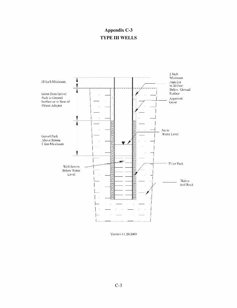
Appendix C-3: Type III Wells C-3
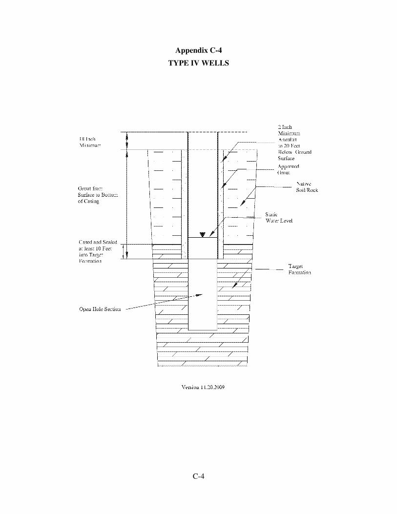
Appendix C-4: Type IV Wells C-4
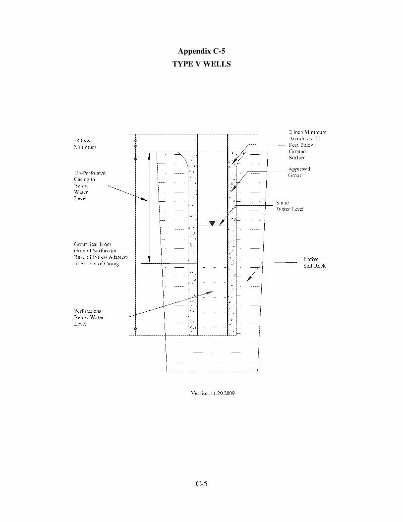
Appendix C-5: Type IV Wells C-5
1-1
PART III
WATER WELL MINIMUM CONSTRUCTION STANDARDS
CHAPTER 1
PURPOSE
Section 1: Purpose and Scope.
(a) The State Engineer, having general supervision of the waters of the state, is
authorized under Section 41-3-909 of the Wyoming Statutes to establish standards for
construction of water wells to protect the use of the state’s ground water resources. The
enactment of federal and state environmental quality law and fostering of safe and clean
water policy has prompted enhanced well head protection measures against
contamination of ground water resources.
(b) Every well constructed or repaired with a withdrawal of well casing after the
adoption of these standards must comply with them. Any deviation from these standards
must be approved in writing by the State Engineer or his designee.
(c) It is the joint responsibility of the drilling and/or pump contractor(s) and well
owners(s) to comply with these standards. Further, the well owner(s) must maintain a
well in a condition so that it does not contribute to contamination (pollution) of the
ground water supply.
(d) If compliance with these Water Well Minimum Construction Standards will
not result in a well that is sufficiently sealed from either surface or subsurface
contamination, then the drilling and/or pump contractor(s) and well owner(s) must use
additional safeguards to protect the ground water supply and its users.
(e) Any waiver or variance to these Water Well Minimum Construction Standards
can only be obtained by applying for the waiver or variance to the State Engineer in
writing. The waiver or variance application shall state the nature of the waiver or
variance and the reasons why the waiver or variance will not result in a well that will
have a detrimental effect on the ground water resource.
(f) Other state and local regulations pertaining to well drilling and construction,
ground water protection, and water quality regulations may exist that are either more
stringent than these rules or that apply to a specific situation. It is the well driller’s
responsibility to understand and apply other regulations as applicable.
(g) Well owners and drillers are advised that local zoning ordinances or county
board of health requirements may limit or restrict the actual well location, construction,
and/or relationship to property/structure boundaries and existing or proposed
concentrated sources of pollution or contamination such as septic tanks, drain fields,
sewer lines, stock corrals, feed lots, etc., beyond the requirements of these standards.
1-2
(h) Well owners and drillers are advised that standards developed under
Wyoming State Law, Title 37, Chapter 12, Article 3 (Damage to Underground Public
Utility Facilities) apply.
(i) Well owners and drillers are advised that the State Engineer’s Office
maintains reporting requirements with regard to certain stages of well completion. These
requirements are addressed in the Wyoming State Engineer’s Office Part II Rules.
Section 2. Authority.
(a) The State Engineer has the authority to establish standards for the construction
of wells. Pursuant to W.S. §41-3-909 (a)(vi) and the Wyoming Administrative
Procedures Act; the State Engineer hereby adopts the following Water Well Minimum
Construction Standards. Every well constructed after the adoption of these standards must
be in compliance with these standards. Deviations from these standards must be approved
by the State Engineer.
2-1
CHAPTER 2
REQUIREMENTS AND DEFINITIONS
Section 1: Statutory Requirements.
(a) “Any person who intends to acquire the right to beneficial use of any
underground water in the state of Wyoming, shall, before commencing construction of
any well or other means of obtaining underground water or performing any work in
connection with construction or proposed appropriation of underground water or any
manner utilizing the water for beneficial purposes, file with the state engineer an
application for a permit to make the appropriation and shall not proceed with any
construction or work until a permit is granted by the state engineer…” (W.S. §41-3-930)
(b) “An appropriator of underground water may change the location of his well to
a point within the same aquifer in the vicinity of the original location, without loss of
priority, by securing approval of the state board of control if the groundwater right has
been adjudicated or if the groundwater right has not been adjudicated but the water has
been applied to beneficial use. In cases involving domestic or stock water wells which are
not adjudicated but the water has been applied to beneficial use, the state engineer may
approve a change of location. If the right is not adjudicated and the water has not been
applied to beneficial use, approval for the change in location may be granted by the state
engineer.” (see W.S. §41-3-917(a))
(c) “It shall be unlawful for any person to construct, alter or rehabilitate a water
well or install pumping equipment in a water well without a license as provided by [W.S.
§33-42-101 through 33-42-117] unless the activity is exempted from the licensing
requirements of [W.S. §33-42-101 through 33-42-117].” (W.S. §33-42-103(f))
(d) “Any person who drills, digs or constructs any works for the securing of
underground water without having obtained a permit is guilty of a misdemeanor and upon
conviction shall be punished under W.S. §41-3-616.” (W.S. §41-3-938)
(e) “Any person who withdraws underground water or who fails to stop or reduce
the flow of underground water in violation of any order of the state engineer made
pursuant to this act, or any person who does not have a permit, certificate or vested right
to appropriate underground water who shall withdraw underground water from any well
other than a well for stock or domestic purposes as defined in W.S. §41-3-907, is guilty
of a misdemeanor and upon conviction shall be punished under W.S. §41-3-616.” (W.S.
§41-3-919)
(f) “[T]he state engineer is authorized and empowered on advice and consent of
the board of control… [t]o require the abatement of any condition, or the sealing of any
well, responsible for the admission of polluting materials into an underground water
supply.” (W.S. §41-3-909(a))
2-2
Section 2: Definitions. For the purposes of Part III of the Regulations and
Instructions of the Wyoming State Engineer’s Office – Ground Water Division, the
following definitions apply:
(a) ACCESS PORT – An opening at the wellhead and/or within the discharge
system where measuring devices or meters may be placed to measure water levels,
pressure, or discharge.
(b) ACRE-FOOT – The volume of water required to cover one (1) acre to a depth
of one (1) foot. One (1) acre-foot equals approximately 325,851 U.S. Gallons.
(c) AIR-HAMMER DRILLING – A system of drilling that employs a pneumatic
bit that delivers percussion strikes to the formation while being slowly rotated. Cuttings
are removed by the compressed air that drives the hammer bit.
(d) ALLUVIUM – Deposits resulting from the operations of rivers, streams, etc.,
thus including sediments laid down in riverbeds, flood plains, lakes, fans at the foot of
mountain slopes, and estuaries.
(e) ANNULAR SPACE (ANNULUS) – The space between two cylindrical
surfaces, one of which surrounds the other, e.g. concentrically; such as the space between
the outer well casing and the borehole wall. An annular space also means the space
between an inner well casing and outer well casing. The annular space is calculated as
the difference in diameter of the borehole (Db) and the outside diameter of the casing (Dc)
divided by two [(Db-Dc)/2], or the difference in the inside diameter of a larger casing (Dl)
and the outside diameter of a smaller casing (Ds) divided by 2 [(Dl-Ds)/2].
(f) AQUIFER – “[A]ny underground geological structure or formation having
boundaries that may be ascertained or reasonably inferred, in which water stands, flows
or percolates.” (W.S. §41-3-901(a)(iii)). (Also see Unconfined, Confined and Perched)
(g) API – The American Petroleum Institute.
(h) ARTESIAN AQUIFER – See Confined Aquifer.
(i) ARTESIAN WELL – A well that derives its water from an artesian or
confined aquifer where the hydrostatic pressure is greater than atmospheric pressure
thereby raising the water level above the top of the aquifer. A flowing artesian well has a
water level that is above the land surface.
(j) ASTM – American Society for Testing and Materials International.
(k) AWWA – The American Water Works Association.
(l) BENTONITE – Clay composed predominantly of the clay mineral
montmorillonite and used commercially in drilling fluids and well sealing products.
2-3
(m) BOREHOLE LOGS – Borehole logs measure and display the physical
properties of the surrounding medium with a sensor located in a borehole. Some
common borehole logging techniques are presented below:
(i) Acoustic (Sonic) Velocity – A borehole log in which the down-hole
tooling has a sound transmitter at one end and two receivers spaced along it. The tool
uses the difference in signal arrival time to calculate the sonic velocity through the strata.
(ii) Caliper – A borehole log which measures the size of the well bore.
Used to measure the diameter of an uncased borehole in bedrock units. Can also be used
to find the casing depth.
(iii) Cement Bond (Bond) – An acoustic log that measures and displays the
return arrival time of an acoustic wave generated within the casing. When steel casing is
strongly bonded to cement, most of the energy of the wave is carried through the casing;
however, when the casing is not strongly bonded to the cement, most of the sound waves
are carried along the casing and the arrival time will be much shorter.
(iv) Focused (Focus) – A borehole log wherein electrodes are designed to
direct electrical current as a disk. This method can yield improved results in high
resistivity strata.
(v) Formation Density (Density) – A borehole log which measures the
rock density.
(vi) Gamma-Gamma Radiation – A borehole log in which a source of
gamma radiation and a detector are lowered into the borehole. The log measures bulk
density of the formation and fluids.
(vii) Gamma-Ray (or Gamma) – A borehole log which measures naturally
occurring gamma radiation emitted by the surrounding strata.
(viii) Induction (or Dual Induction) – A borehole log which measures
spontaneous potential, resistivity, and conductivity.
(ix) Neutron Porosity (Neutron) – A borehole log obtained by lowering a
radioactive element, which is a source of neutrons, and a neutron detector into the well.
The log measures the hydrogen atom density of the surrounding strata and provides an
indication of the formation porosity.
(x) Resistivity – A borehole log which measures the resistivity between
two current electrodes and two additional electrodes. Measures the electrical resistivity
of the formation and contained fluids near the probe.
(xi) Spontaneous Potential (or Self Potential) (SP) – A borehole log made
by measuring the natural electrical potential that develops between the formation and the
2-4
borehole fluids. The SP log is commonly used to assess the permeability of the
surrounding strata.
(n) CABLE-TOOL DRILLING – A drilling technique which is operated by
repeatedly lifting and dropping a heavy drilling string and drilling bit which pulverizes
the encountered material.
(o) CASCADING WATER – Ground water which trickles or pours through
cracks (or other openings), down the cased or uncased borehole above the water level in
the well.
(p) CASING – Any conduit or pipe placed in a well to prevent borehole wall
caving, to protect the production string and pump, and to prevent pollution of the well.
Casing material is most commonly steel, PVC, or concrete.
(q) CEMENT BASKET – A device firmly attached to the casing string that is
designed to tightly fit against the borehole wall that is intended to hold cement above a
desired zone.
(r) CENTRALIZER – A device attached to the outside of a casing or liner to
center it within a borehole or casing.
(s) COLLUVIUM – Loose rock and soil at the base of a cliff or steep slope.
(t) CONFINED (ARTESIAN) AQUIFER – An aquifer bounded above and
below by confining units (or beds) and in which water levels in wells rise above the top
of the aquifer.
(u) CONFINING FORMATION (CONFINING UNIT) – A geologic bed which
displays a significantly lower vertical hydraulic conductivity than an adjacent aquifer.
(v) CONSOLIDATED – Combined or cemented into a single or solid mass; or
lithified (e.g. bedrock formation).
(w) CONSTRUCTION – “[I]ncludes boring, drilling, jetting, digging or
excavating, and installing casing, pump and other devices withdrawing or facilitating the
withdrawal of underground water, or measuring the depth to the water table or flow of the
well.” (W.S. §41-3-901(a)(v)).
(x) CONTAMINANT – Any material responsible for or contributing to pollution.
See POLLUTION.
(y) CUBIC FEET PER SECOND (CFS) – A rate of flow. One (1) cfs equals
448.8 gpm.
(z) DEVELOPMENT – Cleansing of the drilled hole and formation to remove
cuttings, fine grained materials, infiltrated drilling fluids, and/or to enhance aquifer
2-5
permeability. Development can be accomplished by surging, backwashing, jetting,
airlifting, acid-fracture treatment, etc.
(aa) DRILLER – See WATER WELL DRILLING CONTRACTOR.
(bb) DRILLING MUD – A viscous liquid suspension, usually composed of water
and a bentonite–based mixture, which is pumped through the drill stem to equalize
formation pressures, lubricate and cool the drilling bit, and/or aid in removing drill
cuttings to the surface.
(cc) DRILL PIPE (DRILL STEM) – Thick walled pipe used for drilling
operations. Transmits rotation from the rotating mechanism on the drill rig to the bit.
Drill collar, extremely heavy drill pipe, is usually placed in the drill pipe string just above
the bit to provide extra weight and strength.
(dd) DRILLING RIG – The derrick, mast, or standing apparatus together with the
power equipment, pumps, cable and tools used in well drilling. Usually truck-mounted or
trailer mounted.
(ee) DRIVE POINT – A conical shaped point of steel placed at the bottom of a
driven well’s screen to aid in placing the screen at the desired depth.
(ff) DRIVE SHOE – A section of steel casing attached to the bottom of a driven
casing. The drive shoe has a beveled edge and is designed for cutting through rock or
other hard formations.
(gg) DRIVEN WELL – A well which is emplaced by forcefully driving a casing
into the ground (usually deep soil or alluvial material). The leading end of the casing is
usually fitted with a drive point.
(hh) DUG WELL – A large diameter well or trench constructed by digging down
and intercepting the water table or shallowest water-bearing horizon.
(ii) FILTER (GRAVEL) PACK – Clean sand or gravel sized according to
formation texture and emplaced in the annular space of a well between the perforated or
screened interval(s) of the casing and the borehole wall in order to prohibit or decrease
the entrance of formation material into the well, stabilize the borehole, and increase the
efficiency of water production.
(jj) FLOWING WELL – An artesian well in which the water level stands above
the land surface.
(kk) FORMATION – a body of rock or soil which has identifiable and distinctive
lithic characteristics, is aerially extensive, can be mapped, and may be combined into
groups or divided into members.
2-6
(ll) GALLONS PER MINUTE (GPM) – Unit of measure used to describe a flow
rate.
(mm) GEL – A jelly-like fluid and colloidal material (natural or synthetic)
dispersion mixture used as a drilling fluid.
(nn) GROUND (UNDERGROUND) WATER – “[A]ny water, including hot water
and geothermal steam, under the surface of the land or bed of any stream, lake, reservoir,
or other body of surface water, including water that has been exposed to the surface by an
excavation such as a pit.” (W.S. §41-3-901(a)(ii)).
(oo) GROUT – A fluid mixture of water plus a cement-based or bentonite-based
material that is stable, has low permeability, and possesses minimum shrinking properties
such that it is an optimal sealing material for well casing or for well plugging.
(pp) HEAT PUMP WELL – Any well constructed to utilize the heat exchange
properties of either ground water or of geological material penetrated in the well.
(qq) HYDROSTATIC PRESSURE OR HEAD – Pressure of water (or other liquid)
upon a unit area due to the height at which the surface of the water column stands above
the point where the pressure is measured. Expressed as pounds per square inch (p.s.i.) or
actual feet of head.
(rr) LINER – Pipe (steel or plastic), which is smaller in diameter than installed
well casing, that is used to reconstruct (deepen) a well or strengthen unstable conditions
encountered at depth in a well.
(ss) LINER HANGER – A device used to attach or hang liners from the internal
wall of a larger, upper casing string.
(tt) LOST CIRCULATION – Subsurface escape of drilling fluid from a drill hole
into a porous, fractured, or cavernous formation.
(uu) LCM (LOST CIRCULATION MATERIAL) – Material added to drilling fluid
in order to reduce or stop lost circulation conditions.
(vv) MILLIGRAMS PER LITER – Abbreviated mg/l, means milligrams of solute
per liter of solvent.
(ww) MONITORING WELL – A ground water level observation well or a well
from which water samples are retrieved for water chemistry analysis.
(xx) NEAT CEMENT – Used for ground or borehole sealing. Commonly known
as Portland cement of various ASTM designations (Type I through Type V, Type K,
etc.). May be mixed with calcium chloride (CaCl2) for rapid set time or bentonite for
lower conductivity, lower curing temperature, and resistance to shrinking/cracking.
2-7
(yy) NSF – NSF International, formerly National Sanitation Foundation.
(zz) NOMINAL SIZE – Used to describe standard sizes for pipe from 1/8 inch to
12 inches. The term “nominal” is used in designating the inside diameter of the pipe,
because, in practice, the actual size varies somewhat.
(aaa) PACKER – A device used to seal or isolate. In the case of a telescoped casing
and screen assembly, a packer is used to provide a sand-tight seal between the screened
assembly and the casing. An inflatable packer is used to isolate zones of the casing or
borehole for tests or casing repairs.
(bbb) PERCHED AQUIFER – Unconfined ground water which is bounded below
by low-permeability material and separated from an underlying regional body of ground
water by an unsaturated zone.
(ccc) PERFORATIONS – Puncturing, drilling, sawing, slotting, torchcutting, or
other openings of a well casing emplaced in order to allow flow of water from the water-
bearing interval(s) into a cased well. Perforations are typically installed with revolving
wheel cutters, knives, or explosive charges and are created after the casing has been
placed in the borehole.
(ddd) PERMEABILITY – A measure of the ability of a material to transmit fluids.
(eee) PERMIT – The record instrument on which the State Engineer grants
permission to construct a well/spring and beneficially use the water for the purposes
specified, together with any conditions and limitations attached.
(fff) PIEZOMETER – A nonpumping well, generally of small diameter, that is
used to measure the pore pressures, water levels, or potentials. A piezometer generally
has a short well screen through which water can enter.
(ggg) PITLESS ADAPTOR – A commercially manufactured, watertight unit or
device designed for attachment to well casing which permits discharge from the well
below the land surface to provide for a buried, frost-free discharge line.
(hhh) PLUGGED AND ABANDONED WELL (P&A) – Any well which has been
filled or plugged so that it is rendered unproductive and prevents contamination of the
ground water. A properly abandoned well will not produce water nor serve as a channel
for movement of water or other material from the well or between water-bearing zones.
(iii) POLLUTION – “[A]ny impairment of the natural quality of such water,
however caused, including impairment by salines, minerals, industrial wastes, domestic
wastes or sewage, whether indrafted directly or through infiltration into the underground
water supply.” (W.S. §41-3-901(a)(vi))
(jjj) POROSITY – The ratio of the volume of void spaces in a rock or sediment to
the total volume of the rock or sediment. Effective Porosity – the volume of the void
2-8
spaces through which water or other fluids can travel in a rock or sediment divided by the
total volume of the rock or sediment. Primary porosity is the porosity that represents the
original pore openings when a rock or sediment formed. Secondary porosity is the
porosity that has been caused by fractures or weathering in a rock or sediment after it has
been formed.
(kkk) POTENTIOMETRIC SURFACE – A surface that represents the level to
which water will rise in tightly cased wells.
(lll) PRESSURE GROUTING – A process by which a grout is emplaced and
confined within the borehole or casing of a well by the use of retaining plugs, packers, or
a displacing fluid by which sufficient pressure is applied to drive the grout into and
within the annular space or interval to be grouted.
(mmm)PUMP INSTALLER – See WATER WELL PUMP INSTALLATION
CONTRACTOR.
(nnn) PUMP TEST – Pumping a well, usually at time of completion, to determine
aquifer or well performance (e.g., drawdown, maximum efficient gpm, specific capacity,
etc.).
(ooo) PUMPING WATER LEVEL – The water level achieved, during water well
pumping, where the drawdown ceases or stabilizes.
(ppp) PVC CASING OR SCREEN – Polyvinyl chloride polymer (plastic) pipe.
(qqq) RECOVERY WELL – A well primarily designed to remove contaminants,
groundwater, or both, usually in an attempt to contain contaminants or contaminated
groundwater to an area already effected.
(rrr) REHABILITATION – Restoring a well to its most efficient condition. This
may be accomplished by chemical and mechanical methods.
(sss) ROTARY DRILLING – Drilling technique which employs a rotating drill
string through which drilling mud is pumped down hole to cool the drill bit and remove
cuttings to the surface via the borehole outside the drill pipe. Compressed air is also used,
in lieu of drilling fluid, to remove cuttings. Reverse circulation rotary drilling is a method
in which drilling fluid flows from the ground surface down the borehole and is pumped
back to the ground surface through the drill pipe. The reverse rotary method can be
effective for drilling large diameter boreholes and for drilling in unstable material.
(ttt) SANITARY WELL CAP (SEAL) – A vented watertight wellhead cap that
prevents the intrusion of foreign fluids (runoff, chemical liquids, animal waste, etc.) or
debris.
(uuu) SATURATED – All voids are filled with water.
2-9
(vvv) SHALE BASKET – A device firmly attached to the casing string designed to
tightly fit against the borehole wall that is intended to prevent materials from falling into
the intervals below the shale basket setting.
(www) SLIM HOLE – A small diameter exploration borehole drilled to obtain
stratigraphic or structural information.
(xxx) SPRING – A point location where ground water emanates from bedrock or
soil to the land surface.
(yyy) SQUEEZE JOB – Usually a secondary cementing or grouting process where
the sealant is pumped into a borehole through the bottom of the casing or through
perforations at key depths in the casing in order to obtain fluid or formation shut off.
(zzz) STATE ENGINEER – The State Engineer or his designee.
(aaaa) STATIC WATER LEVEL – (1) The elevation or level of the water in a well
when the pump is not operating. Usually measured in depth below the land surface or
from the top of the casing. (2) The level or elevation to which water would rise in a tube
connected to an artesian aquifer when the well is shut in. Usually measured in psi or feet
above ground level.
(bbbb) SURFACE (CONDUCTOR) CASING – Retaining pipe, usually large
diameter steel, concrete or culvert material installed in the uppermost potion of the well
between the borehole wall and the inner well casing.
(cccc) SURFACTANT – An agent that reduces the surface tension of the liquid in
which it is dissolved. Used in air-based drilling to produce foam and during development
to disaggregate clays.
(dddd) TREMIE PIPE (GROUT PIPE) – A small diameter conductor pipe, hose or
tubing used in down hole placement of well construction material (cement, grout mixture,
gravel pack, etc.).
(eeee) UNCONFINED (WATER TABLE) AQUIFER – An aquifer that has no
overlying geologic unit preventing or restricting the vertical or upward movement of
water.
(ffff) UNCONSOLIDATED – A loose aggregation or not combined nor cemented
into a single or solid mass; or unconsolidated deposit (e.g., alluvium).
(gggg) WATER TABLE – The water surface of an unconfined aquifer.
(hhhh) WATER WELL DRILLING CONTRACTOR (DRILLER) – “[A]ny person
responsible for or causing the construction, equipping, test pumping or development of
any water well for compensation or otherwise as provided by [W.S. §33-42-101 through
33-42-117].” (W.S. §33-42-102 (a)(iii))
2-10
(iiii) WATER WELL PUMP INSTALLATION CONTRACTOR (PUMP
INSTALLER) – “[A]ny person who is in the business of installing pumping equipment in
water wells for compensation or otherwise as provided by [W.S. §33-42-101 through 33-
42-117].” (W.S. §33-42-102 (a)(iv))
(jjjj) WELL – “[A]ny artificial opening or excavation in the ground, however
made, by which underground water is sought or through which it flows under natural
pressure or is artificially withdrawn, and a series of wells developed as a unit and pumped
collectively by a single pumping unit shall be considered as one (1) well.” W.S. §41-3-
901(a)(iv) “[A]ny artificial opening in the ground for the production of groundwater or
the disposal of water underground, including developed springs, test wells, monitoring
wells, deep well ground beds (cathodic protection bores), geothermal or heat exchange
wells, drive points and excavations for the purpose of artificial recharge to the
groundwater bodies or disposal of wastes. The term "well" does not include excavations
made for the dewatering of construction sites, mines or oil and gas wells, and the
prospecting for and removal of mineral products, nor wells for the production of the
media for secondary oil recovery.” (W.S. §33-42-102(a)(v))
For the purpose of this document, the following well types are described:
(i) Type I – Dug Wells
(ii) Type II – Natural Filter Wells
(iii) Type III - Artificial Filter Wells
(iv) Type IV – Partially-Cased Open Borehole Wells
(v) Type V – Fully-Cased Wells
(vi) Type VI – Conversion of Existing Oil or Gas Wells, or Exploration
Test Wells into Water Wells
(kkkk) WELL (DRILL HOLE) CUTTINGS – Rock chips or particles cut by the
action of the drill bit and removed from the hole. Cutting samples collected and identified
at evenly spaced intervals provide a lithologic log (detailed description of rock material
encountered in the drill hole).
(llll) WELL SCREEN – A commercially manufactured structurally supporting
filter device that allows inflow, retains select material, and is the access for aquifer
development and future aquifer maintenance. Screen may be continuous-slot wire-
wrapped, pre-packed, louvered, or bridge-slotted or any other commercially
manufactured product which is produced for the purpose of water well screening.
3-1
CHAPTER 3
WELL CONSTRUCTION
Section 1: Water Well Siting.
(a) General Considerations.
(i) All wells shall be sited and constructed in such a manner that the well
does not act as a conduit for the transmission of contaminants from either above or below
ground to the ground water resource. All restriction and setback distances
contained in this section are intended for production wells and do not necessarily apply
(but does not constitute exemption) to choice of location for monitor wells, test wells,
dewatering wells, recovery wells, or oil and/or gas wells which produce by-product
water.
(b) Relation to Land Surface.
(i) Water wells shall be located such that there is adequate surface
drainage away from the well and situated such that the well is easily accessed for repairs,
maintenance, and inspection. For all wells, the top of the casing shall extend at least 18
inches above the finished land surface grade. Well casing may not be terminated at or
near the base of underground well vaults or placed in basements. In the special case of
ground water monitor wells constructed flush with the land surface, the wells shall be
capped with an impact-resistant and water-proof cap.
(c) Relation to Property Lines.
(i) Every well shall be located at least 10 lateral feet from any property
line or boundary.
(d) Relation to Buildings, Structures and Overhead Obstructions.
(i) When a well is proposed to be located adjacent to a building or any
other standing structure, it shall be placed to be as accessible as may be necessary. The
well shall be placed such that the building or any overhead projection from the building
will not be within a 10-foot radius of the surface casing. The well owner is responsible
for maintaining adequate spacing and access following construction.
(ii) Where overhead utility lines or other overhead obstructions are
present, minimum distances from all equipment shall be maintained in accordance with
OSHA standards.
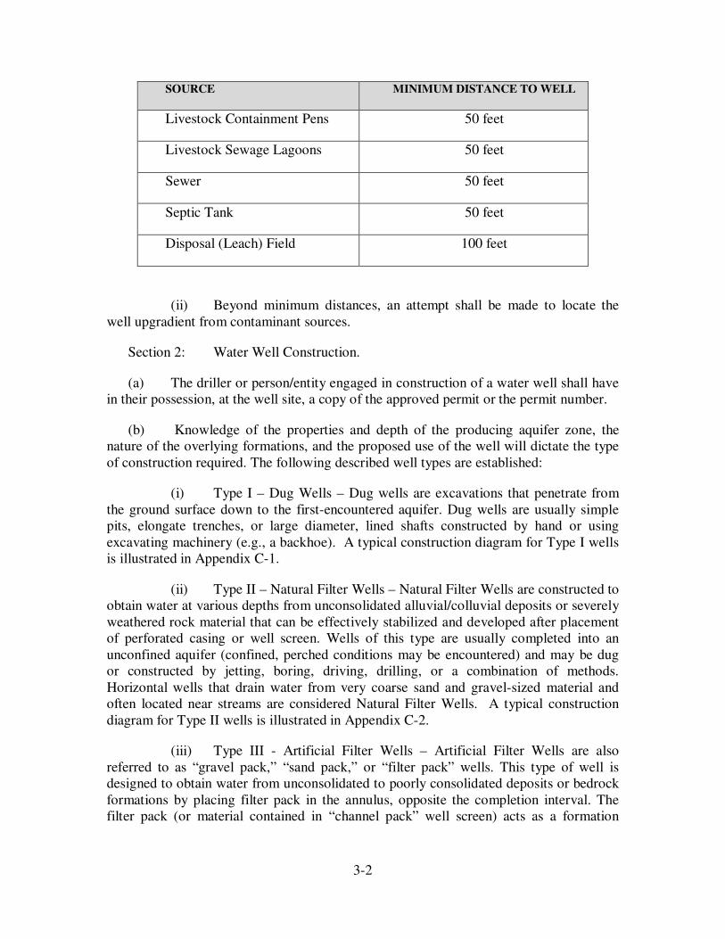
(e) Setback Distances from Contaminant Sources.
(i) Water wells shall be located the minimum lateral distance from any
common pollutant sources listed below:
3-2
(ii) Beyond minimum distances, an attempt shall be made to locate the
well upgradient from contaminant sources.
Section 2: Water Well Construction.
(a) The driller or person/entity engaged in construction of a water well shall have
in their possession, at the well site, a copy of the approved permit or the permit number.
(b) Knowledge of the properties and depth of the producing aquifer zone, the
nature of the overlying formations, and the proposed use of the well will dictate the type
of construction required. The following described well types are established:
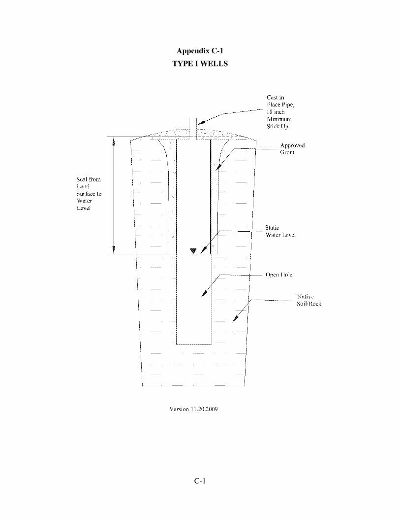
(i) Type I – Dug Wells – Dug wells are excavations that penetrate from
the ground surface down to the first-encountered aquifer. Dug wells are usually simple
pits, elongate trenches, or large diameter, lined shafts constructed by hand or using
excavating machinery (e.g., a backhoe). A typical construction diagram for Type I wells
is illustrated in Appendix C-1.
(ii) Type II – Natural Filter Wells – Natural Filter Wells are constructed to
obtain water at various depths from unconsolidated alluvial/colluvial deposits or severely
weathered rock material that can be effectively stabilized and developed after placement
of perforated casing or well screen. Wells of this type are usually completed into an
unconfined aquifer (confined, perched conditions may be encountered) and may be dug
or constructed by jetting, boring, driving, drilling, or a combination of methods.
Horizontal wells that drain water from very coarse sand and gravel-sized material and
often located near streams are considered Natural Filter Wells. A typical construction
diagram for Type II wells is illustrated in Appendix C-2.
(iii) Type III - Artificial Filter Wells – Artificial Filter Wells are also
referred to as “gravel pack,” “sand pack,” or “filter pack” wells. This type of well is
designed to obtain water from unconsolidated to poorly consolidated deposits or bedrock
formations by placing filter pack in the annulus, opposite the completion interval. The
filter pack (or material contained in “channel pack” well screen) acts as a formation
SOURCE MINIMUM DISTANCE TO WELL
Livestock Containment Pens 50 feet
Livestock Sewage Lagoons 50 feet
Sewer 50 feet
Septic Tank 50 feet
Disposal (Leach) Field 100 feet
3-3
stabilizer, a filter to prevent fine-grained material from entering the well, and also serves
to increase the yield of the well. This type of well is constructed by boring or drilling. A
typical construction diagram for Type III wells is illustrated in Appendix C-3.
(iv) Type IV – Partially-Cased Open Borehole Wells – Partially-Cased
Open Borehole Wells are also referred to as “open-hole” wells. This type of well is
designed to obtain water from consolidated formations that are stable enough to preclude
the need for perforated casing or well screen. Overlying formations, however, are cased
and sealed to prevent caving and cross-connection of water from vertically separate
aquifers. Flowing wells are commonly the result of this type of well construction when
head elevation is greater than ground surface elevation. A typical construction diagram
for Type IV wells is illustrated in Appendix C-4.
(v) Type V – Fully-Cased Wells – Fully-Cased Wells are drilled to
produce water from an aquifer containing multiple water-bearing intervals. Water
production is achieved by screening and/or perforating opposite one or more of the most
viable water-producing aquifer zones. Overlying formations are cemented or grouted off
to prevent caving and aquifer cross-connection. Wells of this type are usually drilled
relatively deep and generally intercept aquifers under confined conditions. A typical
construction diagram for Type IV wells is illustrated in Appendix C-5.
(vi) Type VI – Conversion of Existing Oil or Gas Wells, or Exploration
Test Wells into Water Wells.
(A) Existing oil and gas wells, seismic test holes, or mineral
exploration holes may be converted for use as water wells, provided that the wells can be
completed to conform to minimum construction standards cited herein.
(B) Information on geologic conditions encountered in the well at
the time of the original well drilling shall be used to determine what special construction
standards shall be met in order to eliminate all movement of pollutants into the well or
along the annular space. If no original geologic information is available, a specified
borehole log suite may be required to supplement known information.
(C) A permit to appropriate ground water must be obtained from
the State Engineer prior to commencing construction of the well.
(D) Before any oil or gas exploration hole or well is converted for
use as a water well, the Wyoming Oil & Gas Conservation Commission should be
contacted in order to comply with that Commission’s regulations.
(c) Annulus.
(i) If a fill pipe for gravel is installed, the diameter of the well bore must
be four (4) inches larger than the largest diameter of the casing plus the largest diameter
3-4
of the fill pipe for gravel. A fill pipe for gravel or any other pipe to provide access to the
interior of the well bore must be completely surrounded by the seal.
(ii) All wells shall be constructed with at least a 2-inch annular space
surrounding the outermost casing and extending not less than 20-feet below ground
surface.
(d) Casing.
(i) Casing, surface casing (conductor pipe), liners, and screens shall be of
new or new-like contaminant-free material and free of pits, cracks, breaks, and corrosion.
All pipe, casing, couplings, and screen must meet applicable ASTM, API, NSF, and/or
AWWA standards. Casing shall be of adequate strength and durability to protect the well
against structural failures during construction and use and protect against the entrance of
contaminants during the expected life of the well.
(ii) All casing shall be selected in accordance with the design of the well,
depth of the well, and conditions at the well site. The most common casing materials
allowed for use are carbon-steel and thermoplastic (PVC). Less common casing materials
such as pre-cast concrete, fiberglass, stainless steel, aluminum, various alloy and non-
ferrous metal casing types are allowable where use/conditions dictate and steel or plastic
cannot be used. Choice of casing material, diameter, and wall thickness shall be based on:
(A) Maximum Pumping Rate and Flow Capacity Over the Life of
the Well: The production casing shall be greater than or equal to one nominal size larger
than the down-hole pump assembly.
(B) Geology and Aquifer Conditions: Where multiple casings are
warranted (surface casing, liners, screens, etc.), provisions shall be incorporated to
prevent misalignment, to seal/secure the annulus between casings, and to prevent or
secure from borehole caving.
(C) Installation Method: Difficulty in handling and load strength
must be considered for various well designs, depths of drilling, specific geologic
conditions, and grouting requirements. Re-entered wells (e.g., for liner placement or
plugging back and completing abandoned oil and gas test wells) should be assessed for
competency of the existing casing.
(D) Plumbness and Alignment: A well shall drift off plumb no
more than one degree per 100 feet of borehole. The alignment shall allow a 40-foot long
section of pipe, ½-inch less than the inside diameter of the casing, to pass freely from the
top of the casing through anticipated pump setting depth.
(E) Water Quality: The effects of formation waters that may cause
corrosion, cross-connection of vertically separate aquifers, bacterial growth, surface
water influx, etc., shall be avoided by proper casing selection and installation.
3-5
(F) Well Devices: Decisions on casing material and dimensions
also depend on outfitting of the well which may include choice of pumps, motors, wiring,
transducers, sampling tools, floats, adapters, airline, caps, seals, etc.
(iii) All casing types must achieve watertight connections according to
directions from the manufacturer.
(A) Metal pipe must be welded or joined with threaded couplings.
If the joints are welded, the weld shall be made using welding rods of equal quality to the
most noble metal, shall be at least as thick as the wall thickness of the well casing, and
shall be fully penetrating. Spot welding of joints is prohibited.
(B) PVC pipe may be glued, flush joint thread and coupled, or
spline-lock coupled.
(C) All solvents, pipe dope, and glue must be NSF approved or an
acceptable equivalent. Rivets or screws used in the casing joints shall not penetrate the
inside of the casing.
(iv) Casing shall be installed in accordance with the drilling method used,
borehole condition, formation characteristics, and comprehensive/tensile strength of the
casing material. Only steel casing, equipped with proper drive shoe or drive point, can be
used if the casing is to be installed by jacking or driving. PVC casing shall be installed
only in an oversized drilled hole without driving. PVC casing shall conform to industry
standards and shall be manufactured for the purpose of water well casing.
(v) Casing made of, or which has been exposed to, hazardous or
potentially harmful materials, such as asbestos, shall not be used.
(e) Lost Circulation Material.
(i) The introduction of lost circulation materials (LCMs) shall be limited
to those products which will not present a potential medium for bacterial growth or
contamination. Only LCMs which are non-organic and can be safely broken down and
removed from the borehole may be utilized. Cottonseed hulls, shredded newspaper, or
cedar chips are examples of LCMs which are not allowed.
(f) Well Completion.
(i) Well completion refers to the method employed to allow water to enter
the well from one aquifer. This is accomplished via perforations in the casing or well
screens set adjacent to water-bearing intervals or by allowing water to enter the well
through the open bottom of the casing. Multiple completions, or wells completed into
two or more vertically separate aquifers, are not allowed
(A) The well driller shall:
3-6
(I) Install well screens constructed of material which is
compatible with adjoining casing and is corrosion resistant.
(II) Install well screens or well intakes that prevent the
continued production of sand, silt, or turbid water.
(III) Not install screen or perforated casing within the zone
of maximum dynamic pumping level to prevent cascading water, except in the case of
monitor wells, recovery wells or test wells.
(B) Type II and III wells shall be constructed with well screen (as
defined in Chapter 2) commercially manufactured for the purpose of well construction
and sized appropriately for the grain size of the aquifer materials to be developed by the
well.
(g) Filter Pack.
Filter pack (or gravel pack) material shall consist of clean, well-
rounded, chemically stable grains that are smooth and uniform. The filter material should
not contain more than 2% by weight of thin, flat, or elongated pieces and should not
contain organic impurities or contaminants of any kind. Type III Wells should be gravel
(filter) packed opposite the perforated or screened zone(s) and no more than five (5) feet
above the zone(s). The interval above the gravel pack must be sealed, as described in
these rules, to prevent fluid cross-contamination from the surface or from a shallow
aquifer.
(i) All filter material shall be placed using a method that through common
usage has been shown to minimize bridging of the material between the borehole and the
casing and excessive segregation of the material after it has been introduced into the
annulus and before it settles into place.
(ii) It is not acceptable to place filter material by pouring from the ground
surface unless proper sounding devices are utilized to measure dynamic filter depth,
evaluate pour rate, and minimize bridging and formation of voids.
(h) Well Sealing/Grouting.
(i) Well casing shall be sealed to prevent vertical movement or leakage of
fluid in the annular space between casing and borehole wall. Non-Slurry bentonite grouts
must be in place before significant hydration occurs. Plans for well construction shall
include allowances for maximum effective emplacement of grout as a seal to protect the
source aquifer and/or assure structural integrity of the entire cased well. Well cuttings
are not allowed to be used as grout, filler, or aggregate material for well sealing.
(ii) Selection of grouting material shall meet the technical requirements
for making a proper seal. Grout products shall meet applicable ASTM, API, NSF,
3-7
AWWA, or other recognized industry standards. Grout shall be prepared according to
manufacturer’s directions and shall be mixed as engineered for specific site requirements.
Water wells permitted under the DEQ-WQD may alternately use any grout mixture
specified by DEQ-WQD. For all other wells, the following are approved grout materials:
(A) Neat Cement Grout Slurry must consist of a mixture of
Portland Cement and not more than 6 gallons of clean water per bag (1 cubic foot or 94
pounds) of cement.
(B) Sand Cement Grout Slurry must consist of a mixture of
Portland Cement, sand, and water in the proportion of not more than 1 part by weight of
sand to 1 part of cement with not more than 6 gallons of clean water per bag of cement (1
cubic foot or 94 pounds).
(C) Concrete Grout Slurry must consist of a mixture of Portland
Cement, sand and gravel aggregate, and water in the proportion of at least 1 part by
weight of aggregate to 1 part of cement with not more than 6 gallons of clean water per
bag of cement.
(D) Nonslurry Bentonite Grout must consist of chipped or
pelletized bentonite varieties that are hydrated to manufacturer’s specifications.
(E) Cement/Bentonite Grout Slurry must consist of a mixture of
cement and bentonite in the proportion of not more than 6.5 gallons of water and 3 to 5
pounds of powdered bentonite per 94-pound sack of Portland cement.
(F) Bentonite Grout Slurry means an inorganic mixture of a
minimum 20% by weight solids bentonite, with polymers, water, or other additives for
the yield/rate control, which forms a low permeability seal (not greater than 1 x 10⁻⁷
cm/sec), and is mixed to the manufacturer’s specifications.
(iii) All wells shall have an annular surface seal of grout extending not less
than 20 feet below ground surface or to useable water below ground surface. The surface
seal must be placed in at least a 2-inch annular space. The completed surface seal must
fully surround the outermost casing, be evenly distributed, and be free of voids.
(A) If a temporary surface casing is utilized, the surface casing
shall be removed in conjunction with the placement of the seal. Alternatively, conductor
casing may be sealed permanently in place to a depth of at least 20 feet with a minimum
2-inch annular seal between the largest outside diameter of the surface casing and
borehole wall. If the temporary surface casing is to be removed, the surface casing shall
be withdrawn as sealing material is placed between the outermost permanent well casing
and borehole wall. The sealing material shall be kept at a sufficient height above the
bottom of the temporary surface casing as it is withdrawn, to prevent caving of the
borehole wall.
3-8
(iv) Type I wells, as defined in this section, (b)(i), shall be constructed with
a watertight curbing extending, at a minimum, from 18 inches above the natural ground
level to the static water level. The curbing shall consist of poured cement grout or casing
surrounded by cement grout. Concrete block with cement grout and rock with cement
grout may also be used. The poured cement grout shall not be less than 6-inches thick. If
casing is to be used, the minimum annular space between the casing and the borehole
shall be three inches. A typical construction diagram for Type I wells is illustrated in
Appendix C-1.
(v) Type III Wells, as defined in this section, (b)(iii), shall be grouted
from immediately above the gravel packed interval and shall terminate at the ground
surface or at the base of a pitless adaptor. The seal shall close off all zones above the
gravel-packed interval. If a gravel tube is installed, it shall be sealed with a water-tight
cap. A typical construction diagram for Type III wells is illustrated in Appendix C-3.
(vi) Type IV Wells, as defined in this section, (b)(iv), shall have the entire
production casing string grouted from bottom to top before well completion. The well
shall be drilled and cased at least 10 feet into the upper portion of the target aquifer. If
permeability factors or hydrostatic conditions in the target aquifer will jeopardize a
successful grout job, then the well shall be drilled, cased and cemented into the first
overlying formation which will provide for secure sealing and completion. According to
W.S. §41-3-909 (a)(vii), flowing and non-flowing wells are required to be “…constructed
and maintained as to prevent the waste of underground water either above or below the
land surface.” Grouting shall be accomplished by either one or several methods in which
grout is pumped directly in the annulus (by tremie or grout pipe) or circulated to the
annulus by positive displacement from inside the casing. Before grouting, clean water or
other suitable drilling fluid mixture shall be circulated to clear the borehole and provide
conditions for optimal bonding. Engineered grout volume calculations must include an
excess allowance (e.g. 25%, 50%, 100%, etc.) for losses in the subsurface. It is allowed to
introduce cement or concrete (e.g. Redi-Mix) from the land surface to finish a grout job
so long as a complete seal is attained. A cement bond log of the well may be required to
assure that an adequate seal was set in place. If leaks occur around the well casing or
adjacent to the well, the driller shall complete the well with seals, packers, and/or grout to
eliminate the leak. A typical construction diagram for Type IV wells is illustrated in
Appendix C-4.
(vii) Type V Wells, as defined in this section, (b)(v), shall be grouted from
the ground surface or the base of the pitless adapter to the bottom of the casing. A typical
construction diagram for Type IV wells is illustrated in Appendix C-5.
(i) Well Development – Following construction, all wells shall be cleaned and
developed to remove drilling fluids, drill cuttings, and other foreign materials. Proper
well development functions to establish the best hydraulic connection between the well
and the source aquifer. The well driller shall develop every new well until the produced
water does not contain appreciable amounts of sand, silt, or turbidity. Chemicals used as
development aids such as agents used in acid fracturing, carbon dioxide (CO2) injection,
3-9
formation deflocculation treatment, etc., are also allowed; however, notification to
WDEQ-WQD is required prior to application or introduction of a foreign substance into a
well that is a public water supply source.
Section 3: Water Well Equipping.
(a) All new and old wells (including hand-dug) shall be capped or sealed so that
they do not present a hazard and to prevent the unintended entry of contaminant matter,
surface water, animals, or foreign objects, by utilizing either a welded plate or a sanitary
well cap. All vents installed in the well casing shall open downward and be screened to
prevent the entrance of foreign material. Wells shall be equipped with a minimum ½-
inch diameter access port for water level and drawdown measurement (unless a flowing
well).
(b) Pitless Adapters.
(i) Pitless adapters must be designed and constructed to be water tight and
to prevent contamination of the ground water resource and any potable water. Pitless
adapters must be compatible with the casing material. The driller or pump installer shall
ensure that the pump and column weight do not exceed the casing strength.
(ii) Where a pitless adapter is to be installed, the grout seal must extend
from the pitless unit to at least 20-feet below the ground surface (or to useable water
below ground surface). The area around the pitless unit and surface string may be filled
with bentonite or clean earth to grade level.
(iii) The components of a pitless adapter must allow sufficient clearance
for the insertion and removal of the down-hole pumping assembly.
(c) Pumps and Pumping Equipment.
(i) Special care must be exercised when replacing a pump because
bacteria can easily contaminate what is pulled from the well (pump, drop pipe, electric
wire) and it is difficult to disinfect portions of the electric wire and drop pipe that are
above water level. When pulling a pump, the electric wire should not be allowed to touch
the ground. This may be accomplished by laying plastic on the ground, utilizing a
mechanical system that winds up the electric wire as it is withdrawn from the well, or
other appropriate means. The drop pipe should be placed on pipe racks or other
precautions should be taken to keep it from contacting the ground. If contamination does
occur, special care must be taken to disinfect the contaminated areas.
(ii) A flow meter with instantaneous flow rate and totalizing capability
shall be installed on discharge lines of all water wells or well systems whenever the State
Engineer permit conditions require a flow meter and subsequent reporting of volumetric
use. The flow meter shall be installed in accordance with the manufacturer’s instructions.
3-10
(iii) All pumping systems shall be designed not to exceed the permitted
pumping rate as established by the State Engineer permit, under normal operating
conditions. All electrical and plumbing installations and connections shall be performed
and maintained in accordance with the existing electrical and plumbing codes, and shall
meet the equipment-manufacturer’s specifications.
(iv) The pump and downhole assembly shall be at least one nominal size
smaller in diameter than the production casing.
(v) Pumps shall be installed in accordance with the manufacturer’s
recommendations and shall provide for proper cooling.
(d) Flowing wells are required, by W.S. §41-3-909(a)(vii), “…to be so capped or
equipped [valved] that the flow of water can be stopped when the wells are not in use…”
In addition, the flow shall be controlled in such a manner as not to exceed the flow rate as
established by the State Engineer permit. Additional precautions may be necessary to
prevent freezing of the wellhead or piping.
(e) Unless specifically designed as an injection well, directional flow controls
shall be installed and maintained to prevent water from being forced or siphoned back
into the well.
(f) For irrigation wells with in-line chemical injection systems or for other wells
that are cross-connected with potential contaminant sources or water source(s) of lesser
quality, a backflow prevention device (reduced pressure assembly, single/double check
valve, etc., with vacuum relief) shall be installed to protect the wellhead from
backpressure or back siphonage.
(g) For multiple wells which are connected by a common conveyance system,
controls shall be maintained to ensure that one pump does not overpower another pump
and allow water to be injected into one well bore.
(h) All electrical installations shall be performed and maintained in accordance
with existing electrical codes. A properly licensed electrician must perform all electric
wiring which impacts the operation of the pump or pumping system. This includes
wiring from the pump to the control boxes to the main power supply such as the breaker
box in a house. Licensed Water Well Pump Installation Contractors are advised that
additional licensing requirements may be required by the Wyoming State Fire Marshal’s
Office. The electric wire should be adequately attached to the drop pipe for support and
be installed in accordance with manufacturer’s recommendations.
(i) All plumbing or water supply distribution from the well to the point of entry
hookup shall be installed and maintained in accordance with existing plumbing codes.
4-1
CHAPTER 4
WELL COMPLETION AND MAINTENANCE
Section 1: Disinfection.
(a) Each person who repairs, modifies, works on, or otherwise affects the
physical components of a well shall clean and disinfect the pump, electrical wiring and
controls, drop pipe, and all other equipment each and every time the pump, electrical
wiring and controls, drop pipe, and other equipment is placed into the well. In addition,
each person (or crew) who performs the above tasks shall maintain at all times on every
well site, adequate chlorine compounds to disinfect the well in accordance with the table
found in Appendix A.
(b) The well driller shall:
(i) Clean all casing, tools, drilling equipment, and materials prior to
beginning the drilling and construction of every well.
(ii) Clean all pumping equipment and well construction materials
(including sand or gravel used in an artificial filter-packed well) before placing them in
the well or borehole.
(iii) Ensure that only potable water is used for drilling and for mixing
of sealing material.
(c) The pump installer shall:
(i) Clean all pumping, wiring, and other equipment prior to placement
in the well.
(ii) Clean all materials that may come in contact with down-hole
equipment.
(d) All wells used for drinking or sanitary use shall be disinfected after
construction, reconditioning, or repair (e.g., submersible pump replacement) and before
the well is placed into, or returned to, service.
(i) Following drilling:
(A) If calcium hypochlorite is used, it shall be slowly poured down the
casing and at least 30 minutes shall pass to allow the tablets to fall through the water and
dissolve.
(B) If sodium hypochlorite is used, the solution must reach all parts of
the well. To accomplish this, a tube shall be suspended through the well casing so that it
4-2
reaches the bottom of the well. After it reaches the well bottom, it shall be withdrawn as
the sodium hypochlorite solution is pumped through the tube.
(C) After the chlorine has been applied, the well shall be surged at
least three times to improve the mixing and induce contact of the chlorinated water with
the adjacent aquifer.
(ii) Following pump installation:
(A) Chlorine shall be introduced so that an average chlorine residual of
100 mg/l is in the entire volume of water in the casing and all parts of the plumbing
system (pump, drop-pipe, wiring, pitless assembly, etc.) for a minimum contact period of
not less than two (2) hours (overnight is preferable) before flushing and ridding the
chlorine solution from the well.
(iii)See Appendix A for mixing proportions. Chlorine compounds intended
for home laundry use, pool, or fountain use should not be used if they contain additives
such as antifungal agents, scents, etc.
Section 2: Spring Developments.
(a) “W.S. §41-3-902. Spring waters; perfection of right to use; limitation.
All springs and spring waters where the yield does not exceed twenty-five (25) gallons
per minute and where the use is for domestic or stock purposes only, shall be considered
as groundwater. Perfection of the right to use spring water up to twenty-five (25) gallons
per minute for domestic and stock use shall be made in accordance with the laws
pertaining to groundwater”
(b) Developed spring flow that is 25 gallons per minute or less and is utilized
for stock and/or domestic use is to be permitted with the State Engineer underground
water permitting procedures. Developed spring flow in excess of 25 gallons per minute,
or for uses other than domestic or stock watering, must be permitted under State
Engineer’s Office surface water permitting procedures. For the purposes of water right
permitting, springs or seeps shall be improved or perfected by some artificial means of
collection and/or conveyance. Springs with no artificial means of collection and/or
conveyance cannot be claimed nor permitted under State of Wyoming water laws.
Accepted means of spring development can range from simple piping to an
impoundment, to spring box collection and associated delivery systems. If the spring is a
domestic source of drinking water, setback allowances from contaminant sources should
be employed the same as for well siting and protection for entrance of animals or other
foreign material shall be provided.
Section 3: Water Well Rehabilitation.
(a) When a water well is to be rehabilitated to increase efficiency, all
equipment used shall be clean and as sterile as possible to prevent well to well or well to
4-3
aquifer cross-contamination. All chemical or biological agents to be introduced into a
well shall meet ASTM, API, NSF and/or AWWA standards approved for the application
of well rehabilitation. Physical rehabilitation of the well including jetting, scrubbing,
bailing, etc. shall be performed in a manner that does not compromise the integrity of the
well casing materials, filter pack, and grout materials. When acidizing or flocculating
agents are pumped or removed from a well, it may be necessary to obtain clearance from
the Wyoming Department of Environmental Quality – Water Quality Division (WDEQ-
WQD) for the surface discharge of these agents.
(b) If, in the repair of a well, the old casing is withdrawn, the well shall be
recased in conformance with these rules.
(c) If a liner is installed to prevent leakage of undesirable water into a well,
the annular space between the casing and liner shall be completely sealed by packers,
casing swedging, pressure grouting, or other methods which will prevent the movement
of water between the casing and liner.
Section 4: Water Well Plugging and Abandonment.
(a) When a well is temporarily removed from service, it shall be kept in a
state of good repair. The top of the well casing shall be sealed with a secure watertight
cap that will prevent tampering and entrance of contaminants, animals, or debris.
(b) The well owner is responsible to ensure that any well (including any test
well or replaced well) which is permanently abandoned or removed from service shall be
entirely plugged to prevent contamination from the surface or any other source and to
remove any further hazard potential that an unused well or abandoned drill hole might
pose. All pumps, pipe, wiring, caps, and other obstructions/debris that may interfere with
adequate plugging operations shall be removed from the well. Suitable cement-based
mixtures or bentonite mixtures shall be used for grouting material. If a well is permitted
under DEQ-WQD rules, those rules may be consulted for abandonment procedures. For
all other wells, an abandoned well shall be plugged by one of the following methods in
accordance with type of well completion and subsurface geologic and /or hydrostatic
conditions:
(i) Dug wells or excavations [Type I Wells, see Section 6(a)(i)]
exposing the shallow water table shall be filled to static water level with clean fill such as
gravel or sand. The remaining hole is to be filled with bentonite to 2-feet below ground
surface. The remaining 2 feet shall be filled with native soil and mounded slightly at the
top to allow for settling.
(ii) If possible, casing shall be removed from Type II Wells [See
Section 6(a)(ii)] prior to plugging procedures. Cased or uncased wells in unconsolidated
formations shall be destroyed by placement of clean fill, such as gravel or sand, opposite
the completed (screened, perforated interval) or water bearing zone and then grouting to
the surface. The upper surface portion of the cased well must be cut off a minimum of 18
4-4
inches below ground level and the area back-filled with enough clean soil material to
allow for settling.
(iii) Type III, gravel pack wells [See Section 6(a)(iii)] shall be grouted
from bottom to top in order to accomplish a complete seal. Grout slurries shall not be
poured from the land surface through a column of water. In order to place the grout in
wells with water columns, it shall be pumped via tremie pipe by positive displacement or
similar method (pressure grouted) from the bottom of the well to a sufficient elevation
such that an uninterrupted seal may be emplaced to the land surface. The upper surface
portion of the cased well must be cut off a minimum of 18 inches below ground level and
the area back-filled with enough clean soil material to allow for settling.
(iv) Plugging of open-hole completed wells [Type IV Wells, see
Section 6(a)(iv)] shall consist of grouting the entire well. Necessary pressure grouting
procedures shall be utilized to permanently seal off flow and/or pressure of the artesian
aquifer such that surface or subsurface leakage will not occur.
(v) Type V Wells [see Section 6(a)(v)] shall be decommissioned in the
same manner as that prescribed for Type III Wells.
(vi) Type I, II, or III wells may alternately be grouted from bottom to
top with bentonite grout to create a complete seal.
(c) If there is any question of proper procedure for extraordinary
plugging/abandonment conditions, the State Engineer’s Office, Ground Water Division
must be consulted for instruction before commencement of plugging activities.
(d) Upon completion of plugging and abandonment of a water well, the well
owner shall report the date and method of abandonment to the State Engineer’s Office,
Ground Water Division with reference to the State Engineer permit number issued for the
well and the well location.
Section 5: Water Quality.
(a) The State Engineer recommends that a water quality sample be collected
after well construction and aquifer testing is complete. The sample should be collected in
an acceptable manner and container and submitted to a qualified laboratory for chemical
and/or biological analysis. Additionally, the State Engineer recommends that water
quality samples be collected and analyzed at periodic intervals during the life of the well
for both chemical constituents and biological materials.
(b) If the water well is to be developed for human consumption serving fifteen
(15) or more service connections, or twenty-five (25) or more persons, for sixty (60) days
or more a year, regulations developed under the Federal Safe Drinking Water Act apply.
Specific requirements of the Act are available from the Water Supply Section Region
VIII, U.S. Environmental Protection Agency, 1595 Wynkoop St, Denver, CO 80202.
4-5
The provisions of Chapters 3, 11 and 12 of the Wyoming Water Quality Rules and
Regulations also apply. You are advised that plans and specifications covering the
proposed construction, installation, or modification of any public water supply system
designed for this purpose are required to be submitted to and a permit to construct
obtained prior to the start of construction from, the WDEQ-WQD, Herschler Building –
4W, Cheyenne, WY 82002; phone number: 307-777-7781.
A-1
CHAPTER 5
APPENDICES
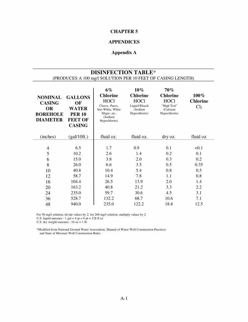
Appendix A
DISINFECTION TABLE* (PRODUCES A 100 mg/l SOLUTION PER 10 FEET OF CASING LENGTH)
NOMINAL
CASING
OR
BOREHOLE
DIAMETER
GALLONS
OF
WATER
PER 10
FEET OF
CASING
6%
Chlorine HOCl
Clorox, Purex,
Sno-White, White
Magic, etc.
(Sodium
Hypochlorite)
10%
Chlorine HOCl
Liquid Bleach
(Sodium
Hypochlorite)
70%
Chlorine HOCl
“High Test”
(Calcium
Hypochlorite)
100%
Chlorine
Cl2
(inches) (gal/10ft.) fluid oz. fluid oz. dry oz. fluid oz
4 6.5 1.7 0.9 0.1 <0.1
5 10.2 2.6 1.4 0.2 0.1
6 15.0 3.8 2.0 0.3 0.2
8 26.0 6.6 3.5 0.5 0.35
10 40.8 10.4 5.4 0.8 0.5
12 58.7 14.9 7.8 1.1 0.8
16 104.4 26.5 13.9 2.0 1.4
20 163.2 40.8 21.2 3.3 2.2
24 235.0 59.7 30.6 4.5 3.1
36 528.7 132.2 68.7 10.6 7.1
48 940.0 235.0 122.2 18.8 12.5
For 50 mg/l solution, divide values by 2; for 200 mg/l solution, multiply values by 2.
U.S. liquid measure - 1 gal = 4 qt = 8 pt = 128 fl oz
U.S. dry weight measure - 16 oz = 1 lb
*Modified from National Ground Water Association, Manual of Water Well Construction Practices
and State of Missouri Well Construction Rules
B-1
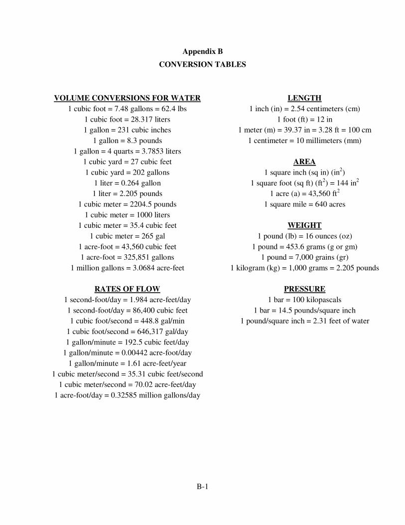
Appendix B
CONVERSION TABLES
VOLUME CONVERSIONS FOR WATER
1 cubic foot = 7.48 gallons = 62.4 lbs
1 cubic foot = 28.317 liters
1 gallon = 231 cubic inches
1 gallon = 8.3 pounds
1 gallon = 4 quarts = 3.7853 liters
1 cubic yard = 27 cubic feet
1 cubic yard = 202 gallons
1 liter = 0.264 gallon
1 liter = 2.205 pounds
1 cubic meter = 2204.5 pounds
1 cubic meter = 1000 liters
1 cubic meter = 35.4 cubic feet
1 cubic meter = 265 gal
1 acre-foot = 43,560 cubic feet
1 acre-foot = 325,851 gallons
1 million gallons = 3.0684 acre-feet
RATES OF FLOW
1 second-foot/day = 1.984 acre-feet/day
1 second-foot/day = 86,400 cubic feet
1 cubic foot/second = 448.8 gal/min
1 cubic foot/second = 646,317 gal/day
1 gallon/minute = 192.5 cubic feet/day
1 gallon/minute = 0.00442 acre-foot/day
1 gallon/minute = 1.61 acre-feet/year
1 cubic meter/second = 35.31 cubic feet/second
1 cubic meter/second = 70.02 acre-feet/day
1 acre-foot/day = 0.32585 million gallons/day
LENGTH
1 inch (in) = 2.54 centimeters (cm)
1 foot (ft) = 12 in
1 meter (m) = 39.37 in = 3.28 ft = 100 cm
1 centimeter = 10 millimeters (mm)
AREA
1 square inch (sq in) (in2)
1 square foot (sq ft) (ft2) = 144 in
2
1 acre (a) = 43,560 ft2
1 square mile = 640 acres
WEIGHT
1 pound (lb) = 16 ounces (oz)
1 pound = 453.6 grams (g or gm)
1 pound = 7,000 grains (gr)
1 kilogram (kg) = 1,000 grams = 2.205 pounds
PRESSURE
1 bar = 100 kilopascals
1 bar = 14.5 pounds/square inch
1 pound/square inch = 2.31 feet of water
C-1
Appendix C-1
TYPE I WELLS
C-2
Appendix C-2
TYPE II WELLS
C-3
Appendix C-3
TYPE III WELLS
C-4
Appendix C-4
TYPE IV WELLS
C-5
Appendix C-5
TYPE V WELLS