Embed Size (px)
Citation preview

PW-5000Enclosure
Installation Manual Part Number: PW5K2ENC1
PW5K2ENC2
TD1151 rev 1101

PW-5000 Enclosure PW5K2ENC1 & PW5K2ENC2 3Installation Guide
TD1151 rev1101
Contents
Warnings and Cautions ................................................................................... 4Disclaimer........................................................................................................... 6Product Liability; Mutual Indemnification................................................................ 6Unpacking Procedure ........................................................................................... 6CAUTION ........................................................................................................... 6Shipping Instructions ............................................................................................ 7Limited Warranty ................................................................................................. 7Confidentiality ..................................................................................................... 8
PW-5000 Enclosure...................................................................................... 9Description .......................................................................................................... 9Dimensions ....................................................................................................... 10Conduit Knockouts ............................................................................................. 10Power Supply ..................................................................................................... 10Maintenance ..................................................................................................... 10Installation Instructions ....................................................................................... 10Installation Diagram .......................................................................................... 11
UL1076 Setup ............................................................................................. 12PC Minimum Requirements ................................................................................. 12Peripheral Hardware Requirements...................................................................... 12Operating System Requirements ......................................................................... 12Software Packages Required ............................................................................... 12Receiving Unit minimum configuration ................................................................ 12Priority of incoming signals for UL1076 ............................................................... 12Other UL1076 Notes ......................................................................................... 13Procedures ........................................................................................................ 13Second PC Installation ....................................................................................... 14Enterprise Manager Setup .................................................................................. 14Pre-Redundancy Verification: ............................................................................... 15DTS Package Verification .................................................................................... 15Interim Steps Before Full Redundancy Verification ................................................. 15Redundant Test Examples ................................................................................... 16Dimensions ....................................................................................................... 16Conduit Knockouts ............................................................................................. 17Power Supply Enclosure ...................................................................................... 17Installation Diagram .......................................................................................... 17Dimensions ....................................................................................................... 17Installation Instructions ...................................................................................... 18
Cable Specifications .................................................................................. 19NexWatch Cable Part Numbers ................................................................ 20NOTES ........................................................................................................ 21

4 PW-5000 Enclosure PW5K2ENC1 & PW5K2ENC2Installation Guide
TD1151 rev1101
Warnings and Cautions
WARNING
Before installation, TURN OFF the external circuit breaker which supplies power to thesystem.
Before connecting the device to the power supply, verify that the output voltage is withinspecifications of the power supply.
Do not apply power to the system until after the installation has been completed.Personal injury or death could occur, and the equipment could be damaged beyond repairif this precaution is not observed!
WARNING
Fire Safety and Liability Notice
Never connect card readers to any critical entry, exit door, barrier, elevator or gate withoutproviding an alternative exit in accordance with all fire and life safety codes pertinent tothe installation. These fire and safety codes vary from city to city and you must getapproval from local fire officials whenever using an electronic product to control a door orother barrier. Use of egress buttons, for example, may be illegal in some cities. In mostapplications, single action exit without prior knowledge of what to do is a life safetyrequirement. Always make certain that any required approvals are obtained in writing. DONOT ACCEPT VERBAL APPROVALS, THEY ARE NOT VALID.
NexWatch never recommends using the PW-5000 or related products as a primary warningor monitoring system. Primary warning or monitoring systems should always meet localfire and safety code requirements. The installer must also test the system on a regularbasis by instructing the end user in appropriate daily testing procedures. Failure to test asystem regularly could make installer liable for damages to the end user if a problemoccurs.
WARNING
EARTH ground all enclosures, for proper installation.EARTH ground can be obtained through the power supply or by grounding the cabinet,BUT NOT BOTH!
WARNING
Use suppressors on all door strikes. Use S-4 suppressors for installation. NexWatchrecommends only DC strikes.
The information in this document is subject to change without notice.

PW-5000 Enclosure PW5K2ENC1 & PW5K2ENC2 5Installation Guide
TD1151 rev1101
CAUTION
If any damage to the shipment is noticed, a claim must be filed with the responsiblecommercial carrier.
CAUTION
Electro-static discharge can damage CMOS integrated circuits and modules.
To prevent damage always follow these procedures:
Use static shield packaging and containers to transport all electronic components,including completed reader assemblies.
Handle all ESD sensitive components at an approved static controlled workstation. Theseworkstations consist of a desk mat, floor mat and an ESD wrist strap. Workstations areavailable from various vendors.
NOTICE
This equipment has been tested and found to comply with the limits for a Class A digitaldevice, pursuant to part 15 of the FCC Rules when wired using metal conduit for thecabling external to the enclosure. These limits are designed to provide reasonableprotection against harmful interference when the equipment is operated in a commercialenvironment. This equipment generates, uses, and can radiate radio frequency energyand, if not installed and used in accordance with the instruction manual, may causeharmful interference to radio communications. Operation of this equipment in a residentialarea is likely to cause harmful interference that will require correction at the users ex-pense.
NOTICE
This document and the data in it shall not be duplicated, used or disclosed to others forprocurement or manufacture, except as authorized by and with the written permission ofNexWatch, Inc. The information contained in this document or in the product itself isconsidered the exclusive property and trade secrets of NexWatch. Copyright laws of theUnited States protect all information in this document or in the software product itself.
NOTICE
Any use of this product is subject to the terms and acceptance of the NexWatch SoftwareAgreement. Please request a copy from NexWatch, and review the agreement carefully.

6 PW-5000 Enclosure PW5K2ENC1 & PW5K2ENC2Installation Guide
TD1151 rev1101
Disclaimer
Product Liability; Mutual Indemnification
In the event that a Customer receives a claim that a Product or any component thereofhas caused personal injury or damage to property of others, Customer shall immediatelynotify NexWatch in writing of all such claims. NexWatch shall defend or settle such claimsand shall indemnify and hold Customer harmless for any costs or damages includingreasonable attorneys’ fees which Customer may be required to pay as a result of thedefective Product or the negligence of NexWatch, its agents, or its employees.
Customer shall hold harmless and indemnify NexWatch from and against all claims,demands, losses and liability arising out of damage to property or injury to personsoccasioned by or in connection with the acts or omissions of Customer and its agents andemployees, and from and against all claims, demands, losses and liability for costs offees, including reasonable attorneys’ fees, in connection therewith.
Unpacking Procedure
CAUTION
If any damage to the shipment is noticed before unpacking, a claim must be filed with thecommercial carrier.
All containers should be opened and unpacked carefully in order to prevent damage to thecontents.
The following steps are used to unpack equipment in preparation for installation:
1. Open the container and remove the unit(s) and all packing material. Retain thecontainer and all packing materials. They may be used again for reshipmentof the equipment, if needed.
2. Inspect the contents for shortage. If items are missing, contact the order entrydepartment at 800-227-1667 Option-2.
3. Visually check contents. If damage is discovered, perform the following:
If shipping caused damage to the unit, a claim must be filed with thecommercial carrier.
If any other defect is apparent, call 800-227-1667 Option-2 for a return authorization.

PW-5000 Enclosure PW5K2ENC1 & PW5K2ENC2 7Installation Guide
TD1151 rev1101
Shipping Instructions
To ship equipment back to NexWatch:
1. Contact the customer service department before returning equipment at 800-227-1667Option-2. Please have the following available when calling:
• A description of the problem or reason for returning the equipment.
• Original purchase order number, invoice number and if the unit is under warranty.
• A new purchase order number if the unit is not under warranty
2. From the customer service department, obtain the Return Authorization Number (RMA).
3. Show the RMA number on all packages shipped. Packages, which are not marked withan RMA number will be refused at the factory and returned COD.
4. Carefully pack the equipment for shipment. Use the original packing material wheneverpossible.
Limited Warranty
All Products sold or licensed by NexWatch include a warranty registration card whichmust be completed and returned to NexWatch by or on behalf of the end user in order forNexWatch to provide warranty service, repair, credit or exchange. All warranty work shallbe handled through Customer which shall notify NexWatch and apply for a Return Mer-chandise Authorization (RMA) number prior to returning any Product for service, repair,credit or exchange. NexWatch warrants that its Products shall be free from defects inmaterials and workmanship for a period of two years from date of shipment of the Productto Customer. The warranty on Terminals, Printers, Communications Products and Upgradekits is 90 days from date of shipment. Satisfaction of this warranty shall be limited torepair or replacement of Products which are defective or defective under normal use.NexWatch’ warranty shall not extend to any Product which, upon examination, is deter-mined to be defective as a result of misuse, improper storage, incorrect installation,operation or maintenance, alteration, modification, accident or unusual deterioration of theProduct due to physical environments in excess of the limits set forth in Product manuals.THERE ARE NO WARRANTIES WHICH EXTEND BEYOND THIS PROVISION. THISWARRANTY IS IN LIEU OF ALL OTHER WARRANTIES WHETHER EXPRESS, IMPLIEDOR STATUTORY, INCLUDING IMPLIED WARRANTIES OF MERCHANTABILITY ORFITNESS FOR ANY PARTICULAR PURPOSE. NO REPRESENTATION OR WARRANTYOF THE DISTRIBUTOR SHALL EXTEND THE LIABILITY OR RESPONSIBILITY OF THEMANUFACTURER BEYOND THE TERMS OF THIS PROVISION. IN NO EVENT SHALLNEXWATCH BE LIABLE FOR ANY RE-PROCUREMENT COSTS, LOSS OF PROFITS,LOSS OF USE, INCIDENTAL, CONSEQUENTIAL OR SPECIAL DAMAGES TO ANYPERSON RESULTING FROM THE USE OF NEXWATCH’ PRODUCTS.

8 PW-5000 Enclosure PW5K2ENC1 & PW5K2ENC2Installation Guide
TD1151 rev1101
Confidentiality
All software, drawings, diagrams, specifications, catalogs, literature, manuals and othermaterials furnished by NexWatch relating to the design, use and service of Products shallremain confidential and shall constitute proprietary rights of NexWatch, and Customeragrees to treat such information as confidential. Customer shall acquire no rights in thedesign of Products or the related materials except to use such information solely for thepurpose of and only during the time it sells Products. Customer shall not copy the designof any Products or use or cause to be used any Product design or related materials for itsown benefit or for the benefit of any other party. The covenants contained in this sectionshall remain effective throughout the term of this Agreement and thereafter unless specifi-cally waived by NexWatch in writing.
PW-5000 Enclosure PW5K2ENC1 & PW5K2ENC2 9Installation Guide
TD1151 rev1101
PW-5000 Enclosure
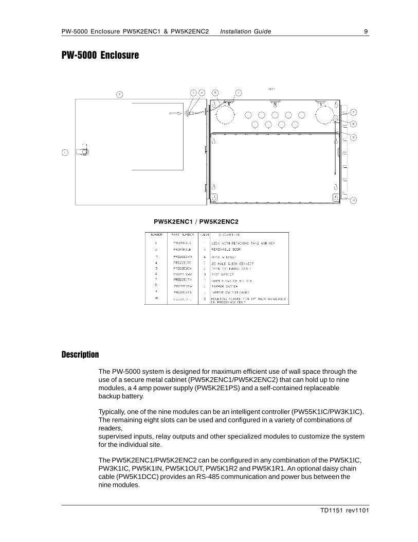
Description
The PW-5000 system is designed for maximum efficient use of wall space through theuse of a secure metal cabinet (PW5K2ENC1/PW5K2ENC2) that can hold up to ninemodules, a 4 amp power supply (PW5K2E1PS) and a self-contained replaceablebackup battery.
Typically, one of the nine modules can be an intelligent controller (PW55K1IC/PW3K1IC).The remaining eight slots can be used and configured in a variety of combinations ofreaders,supervised inputs, relay outputs and other specialized modules to customize the systemfor the individual site.
The PW5K2ENC1/PW5K2ENC2 can be configured in any combination of the PW5K1IC,PW3K1IC, PW5K1IN, PW5K1OUT, PW5K1R2 and PW5K1R1. An optional daisy chaincable (PW5K1DCC) provides an RS-485 communication and power bus between thenine modules.
PW5K2ENC1 / PW5K2ENC2

10 PW-5000 Enclosure PW5K2ENC1 & PW5K2ENC2Installation Guide
TD1151 rev1101
DimensionsENC1 ENC2
Height: 13.9" [0.353 m] 13.9" [0.353 m]Width: 17" [0.4318 m] 18.9" [0.48006 m]Depth: 9" [0.2286 m] 9" [0.2286 m]
Metal thickness: .05" [1.27 mm]Color: Autumn White
Installation holes: Four hangers in a rectangular pattern 12.1” [0.30734 m] H x 16"[0.40640 m] W
Conduit Knockouts
½" [0.0127 m] 2" [0.05080 m]
Back: 9 2Top: 9 2Right Side: 2 1Left Side: 2 1
Power Supply
Use PW5K2E1PS or other approved power supply. (See Installation Manual for details).
Maintenance
Oil lock once per year. If battery backup is used, change battery every 2 to 2 1/2 years.
Installation Instructions
1. Measure and install four mounting screws with heads smaller than .4" [0.01016 m]using proper techniques for the material on which the PW-5000 is being mounted. Usea rectangular screw pattern 12.1" [0.30734 m] H x 16" [0.40640 m] W. Leave thescrews exposed approximately 1/2" [0.0127 m].
2. Open the door of the enclosure and place the hanging slots over the mounting screws.Push the enclosure over the mounting screws and allow the screws to slide into theslots. Finish tightening the mounting screws to securely hold the enclosure.
3. Run all appropriate wiring to the case. Mark each wire as to the panel, location andinput type. All cable shields should tie to one of the grounding lugs found at the top ofthe enclosure.
4. Install the required panels into the metal runners. The PW5K2E1PS should be placedin the right most location and installed according to its own instruction manual. ThePW5K1IC should be installed next to it as the right-most panel.
5. Wire the readers, input and output connections (see wiring guide at end of manual)
PW-5000 Enclosure PW5K2ENC1 & PW5K2ENC2 11Installation Guide
TD1151 rev1101
6. CHECK ALL CONNECTIONS PRIOR TO POWERING UP THE ENCLOSUREAND PANELS.
7. The remainder of the panels can be manually wired for power and RS-485communications using 18 AWG wire. The wires will be daisy-chained from one panelto the next so the power and the communications are wired in parallel. PW5K1DCC isavailable as an option to be purchased with the equipment. This will reduce wiring timein the field since the power and RS-485 communications between panels is factory-wired in a harness that plugs into the bottom two connectors on each panel. The onlyfield wiring required is the two wiring connections of the red and black 12 VDC cablesconnecting the PW5K1DCC and the PW5K2E1PS power supply.
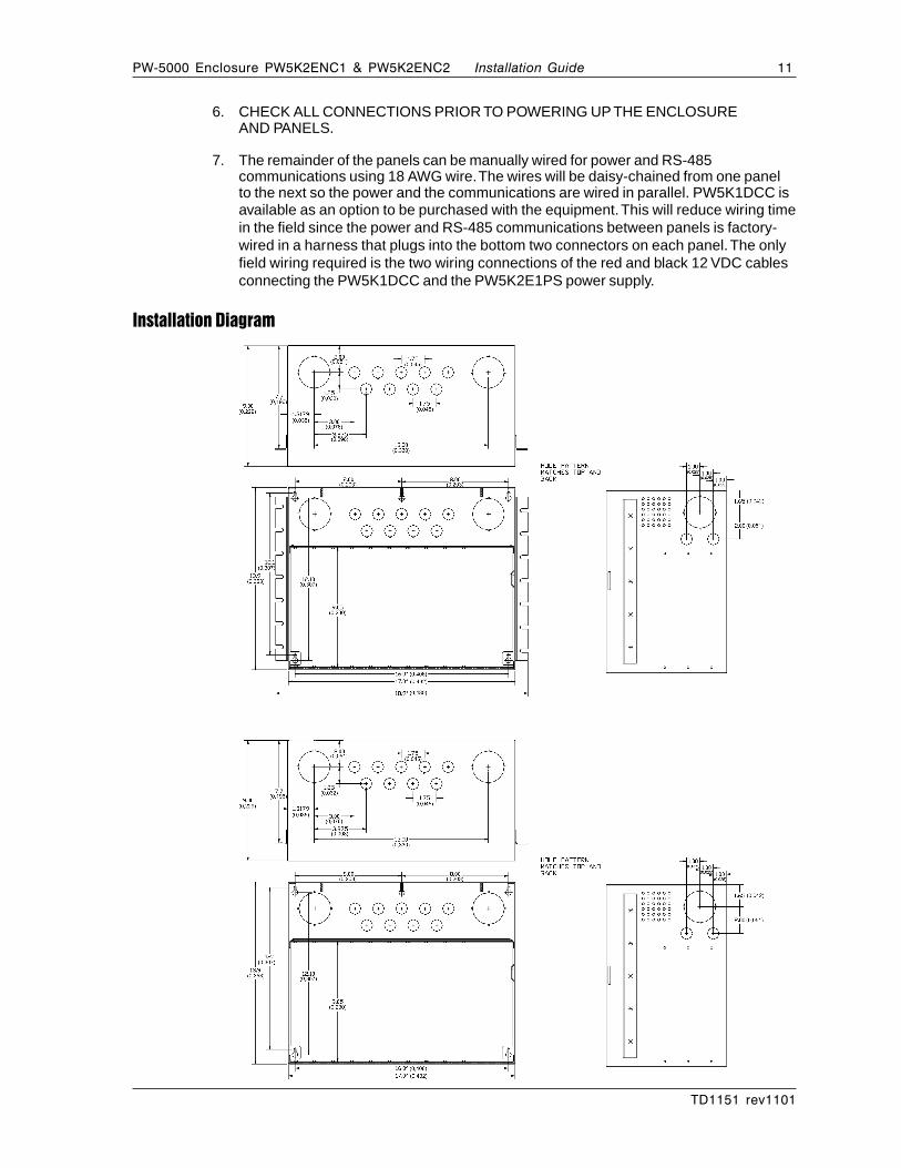
Installation Diagram
PW5K2ENC1
PW5K2ENC2
12 PW-5000 Enclosure PW5K2ENC1 & PW5K2ENC2Installation Guide
TD1151 rev1101
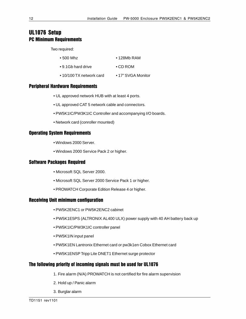
UL1076 SetupPC Minimum Requirements
Two required:
• 500 Mhz • 128Mb RAM
• 9.1Gb hard drive • CD ROM
• 10/100 TX network card • 17” SVGA Monitor
Peripheral Hardware Requirements
• UL approved network HUB with at least 4 ports.
• UL approved CAT 5 network cable and connectors.
• PW5K1IC/PW3K1IC Controller and accompanying I/O boards.
• Network card (conroller mounted)
Operating System Requirements
• Windows 2000 Server.
• Windows 2000 Service Pack 2 or higher.
Software Packages Required
• Microsoft SQL Server 2000.
• Microsoft SQL Server 2000 Service Pack 1 or higher.
• PROWATCH Corporate Edition Release 4 or higher.
Receiving Unit minimum configuration
• PW5K2ENC1 or PW5K2ENC2 cabinet
• PW5K1E5PS (ALTRONIX AL400 ULX) power supply with 40 AH battery back up
• PW5K1IC/PW3K1IC controller panel
• PW5K1IN input panel
• PW5K1EN Lantronix Ethernet card or pw3k1en Cobox Ethernet card
• PW5K1ENSP Tripp Lite DNET1 Ethernet surge protector
The following priority of incoming signals must be used for UL1076
1. Fire alarm (N/A) PROWATCH is not certified for fire alarm supervision
2. Hold up / Panic alarm
3. Burglar alarm

PW-5000 Enclosure PW5K2ENC1 & PW5K2ENC2 13Installation Guide
TD1151 rev1101
4. Watchman tour
5. Fire alarm supervision (N/A) PROWATCH is not certified for fire alarm supervision
6. Burglar alarm supervision
7. Industrial supervision
8. Other supervisory services
NOTE: 2 and 3 may have equal priority: 5 and 6 may have equal priority &7 and 8 may have equal priority
Other UL1075 Notes
• All alarms and troubles must be acknowledged by attending guard.
• Reports of all alarms and troubles must be printed and stored at least once per week.
• When communications are disrupted from the protected area unit to the CentralSupervisory station all panels must be buffered. They must transmit all stored alarmsand troubles to the Central Supervisory Station when communications are restored.
• If Cameras are used they must be UL approved. Camera operation was not verified byUL.
• Guard Tour was not verified by UL to NFPA 72 standards
• Exit and Entry Delay can not exceed 60 seconds. Polling of a receiving unit maynot exceed 200 seconds
Procedures
1. Configure the PC’s by installing the Windows 2000 Server.
A. PC names should be unique and described with Alpha characters.
B. IP addresses should be unique and have the same Subnet Mask.
C. Each PC should be of the same workgroup name.
2. Install Windows 2000 Service Pack 2 or higher.
3. Install SQL Server 2000. Select either NT Authentication or Local System, but beconsistent with both PC installations.
4. Install SQL Server 2000 Service Pack 1.
5. Setup the Lantroix PW5K1EN or PW3K1EN per it’s installation manual.
6. Create a domain admin user account.
7. Install the PROWATCH Software on the MAIN PC.
A. Select Full Installation.
B. Select SQL for Database.
C. Upon reboot of the PC, stop the PROWATCH Service.

14 PW-5000 Enclosure PW5K2ENC1 & PW5K2ENC2Installation Guide
TD1151 rev1101
8. Launch the User Interface.The database should now be programmed to accommodatethe PW5K1IC panel and accompanying I/O boards. Refer to the PROWATCH Installa-tion Manual for additional detail. The programming should continue until the system isfully functional and communications have been established. Below are the program-ming requirements for setting up the PW5K1IC panel.
A. TCP/IP channel selection required when adding a new PW5K1IC.
B. Unique TCP/IP address is required for assignment to the panel and should matchthe IP address you programmed through the Ethernet setup software.
C. Program all the downstream devices for the hardware so that you will be able tomonitor the points and system alarms.
D. Once the program is configured, shut down the User Interface and restart theservice. Launch the User Interface and verify communications.
E. Program a Control Map and/or Floorplans with the hardware. Example: Panels,SIO boards, Inputs, Outputs, readers, Comm Server.
NOTE: Use the SQL Enterprise Manger to backup the programmed database. Refer tothe SQL Server Manual for instructions.
CAUTION: If the instructions describing the Data Transformation Services are notfollowed exactly your database could be overwriten.
Second PC Installation
Follow Instructions 1 through 4 and 7 through 8 listed on pages 12 and 13.
Enterprise Manager Setup
1. Open up Enterprise Manager from the secondary PC, the PC you will use for Redun-dancy.
2. Right-click and expand the SQL Server Group.
3. Right-click and expand the Computer Name Group.
4. Right-click on the PROWATCH Database and select All Tasks then Import Data.
5. Click Next. Verify that the Server is selected as MAIN. The database should bePROWATCH. (The source database)

PW-5000 Enclosure PW5K2ENC1 & PW5K2ENC2 15Installation Guide
TD1151 rev1101
6. Click Next. Change the Server to match the name of the LOCAL PC. The databaseshould be selected as PWNT from that Server. (The destination database).
7. Click Next. Select Transfer objects and data between SQL Server database.
8. Click Next. Uncheck the Create destination objects box.
9. Click Next. Check the Create DTS package for replication box. Also check the SaveDTS Package box. Leave the radial button set for SQL Server. This menu saves thereplication using a DTS package which will be run when the user wants to keep thedatabase current with the MAIN PC.
10. Click Next. Change the name or accept the default for the local package beingcreated. Leave the Server name as LOCAL. Select either NT Authentication or SQLServer Authentication, whichever matches your requirements.
11. Click Next. Select finish and DO NOT ABORT THIS PROCESS. This DTS processwill import all the data from the MAIN PC to the Redundant PC. When the transfer issuccessful, click OK.
12. If a Publication Wizard opens select Cancel. Use the SQL Server Manual to utilizethis feature later, however it is not required for this setup. Click Done and minimizeEnterprise Manager.
Pre-Redundancy Verification:
1. Stop all the services on the MAIN PC.
2. Start services on the Redundant PC and launch the User Interface. Log in as ADMIN.
3. Verify that the data is consistent with the MAIN PC.
4. Verify communication with the hardware by using the Alarm View, Control Map orFloorplans.
5. Next, close the user interface and stop the services on the Redundant PC.
DTS Package Verification
1. Maximize Enterprise Manager and locate the Data Transformation Services Folder.Expand the folder and the click on Local Packages.
2. Find the Local Package that was created earlier. Double-click on the package to openup the DTS menu. Select Package on the menu bar and then Execute.
3. The DTS package will run until it is done transferring the data from the MAIN PC tothe REDUNDANT one.
4. Follow steps 1-5 in the Pre-Redundancy Section on page 14.
Interim Steps Before Full Redundancy Verification
1. Shut down the Redundant PC.
2. Restart all the service on the MAIN PC. Launch the User Interface and verify thatcommunications have resumed.

16 PW-5000 Enclosure PW5K2ENC1 & PW5K2ENC2Installation Guide
TD1151 rev1101
Redundant Test Examples
NOTE: Stop watch needed for all three test examples.
Example #1
1. Use the MAIN PC’s OFF button to shut it down. Turn on the REDUNDANT PC andstart the stop watch.
2. Log into NT with Administrator rights.
3. Launch the User Interface.
4. Open the Event Viewer. When the Returned Panel Communications Normal appears,stop the stop watch. This time represents the amount of time that has passed sincethe MAIN PC went down.
Example #2
1. Unplug the power to the MAIN PC. Turn on the REDUNDANT PC and start the stopwatch.
2. Log into NT with Administrator rights.
3. Launch the User Interface.
4. Open the Event Viewer. When the Returned Panel Communications Normal appears,stop the stop watch. This time represents the amount of time that has passed sincethe MAIN PC went down.
Example #3
1. Unplug the network cable from the HUB for the MAIN PC. Turn on the REDUN-DANT PC and start the stop watch.
2. Log into NT with Administrator rights.
3. Launch the User Interface.
4. Open the Event Viewer. When the Returned Panel Communications Normal appears,stop the stop watch. This time represents the amount of time that has passed sincethe MAIN PC went off line.
Power Supply Dimensions
Height: 15.5" (39.4cm)
Width: 12" (30.5cm)
Depth: 4.5" (11.43cm)
Color: Grey
Installation holes: Four hangers in a rectangular pattern 13.5" H x 9.825" W (34.3cmH x 25cm W)

PW-5000 Enclosure PW5K2ENC1 & PW5K2ENC2 17Installation Guide
TD1151 rev1101
Power Supply Enclosure
+ D
C -
AL400ULXB
L G N
ALTRONIX CORP.BKLYN, N.Y.
11220
MADE INUSA
PTC3
NO C NC NO C NC
+ B
AT
-
DC
24V -
OPEN12V -
CLOSED
ACFAIL
RL2
BATFAIL
RL1
RL3
DC Outputto devices(power limited)
Battery and ACSupervision Circuit(non-power limited)
CAUTION: De-energize unit prior to servicing.For continued protection against fire hazard replacefuse with the same type and rating 3.5A, 250V
Green Lead
Battery connection
(non power limited)
Switch Position:24VDC = SW1 OPEN12VDC = SW1 CLOSED
SW1
Wire Strap
(from Enclosure to Door)
115 powermains
Fuse
StrainRelief
To Battery Enclosurewith 40AH Battery
AL400ULX Assembly diagram for use with the PRO22ENC1 and PRO22ENC2 for UL1076Installation Diagram
Dimensions.875" 1.3"
2"
1.22"
3.25"
1"2"
1.22"
1.25"2.2"
15.5"
(2.22cm)(3.1cm)
(5.08cm)
(3.3cm)
(2.54cm)
1"(2.54cm)
(39.4cm)
(5.1cm)
(3.09cm)
(8.25cm)
(5.58cm)
(3.16cm)
(5.71cm) (9.34cm) (11.6cm)2.25" 3.68" 4.56"
1.22"
12"
4.5"
(30.5cm)
(3.1cm)
(11.4cm)
(5.71cm) (9.34cm) (11.6cm)2.25" 3.68" 4.56"
1.22"(3.1cm)
Conduit Knockouts
3/4”
Top: 3
Bottom: 3
Right Side: 3
Left Side: 1
ALTRONIX AL400 ULX (PW5K1ESPS)
18 PW-5000 Enclosure PW5K2ENC1 & PW5K2ENC2Installation Guide
TD1151 rev1101
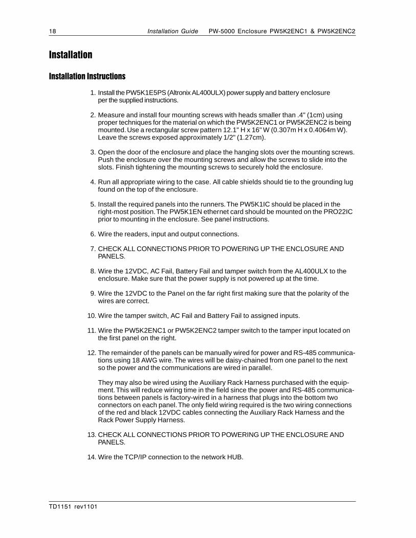
Installation
Installation Instructions
1. Install the PW5K1E5PS (Altronix AL400ULX) power supply and battery enclosureper the supplied instructions.
2. Measure and install four mounting screws with heads smaller than .4" (1cm) usingproper techniques for the material on which the PW5K2ENC1 or PW5K2ENC2 is beingmounted. Use a rectangular screw pattern 12.1" H x 16" W (0.307m H x 0.4064m W).Leave the screws exposed approximately 1/2" (1.27cm).
3. Open the door of the enclosure and place the hanging slots over the mounting screws.Push the enclosure over the mounting screws and allow the screws to slide into theslots. Finish tightening the mounting screws to securely hold the enclosure.
4. Run all appropriate wiring to the case. All cable shields should tie to the grounding lugfound on the top of the enclosure.
5. Install the required panels into the runners. The PW5K1IC should be placed in theright-most position. The PW5K1EN ethernet card should be mounted on the PRO22ICprior to mounting in the enclosure. See panel instructions.
6. Wire the readers, input and output connections.
7. CHECK ALL CONNECTIONS PRIOR TO POWERING UP THE ENCLOSURE ANDPANELS.
8. Wire the 12VDC, AC Fail, Battery Fail and tamper switch from the AL400ULX to theenclosure. Make sure that the power supply is not powered up at the time.
9. Wire the 12VDC to the Panel on the far right first making sure that the polarity of thewires are correct.
10. Wire the tamper switch, AC Fail and Battery Fail to assigned inputs.
11. Wire the PW5K2ENC1 or PW5K2ENC2 tamper switch to the tamper input located onthe first panel on the right.
12. The remainder of the panels can be manually wired for power and RS-485 communica-tions using 18 AWG wire. The wires will be daisy-chained from one panel to the nextso the power and the communications are wired in parallel.
They may also be wired using the Auxiliary Rack Harness purchased with the equip-ment. This will reduce wiring time in the field since the power and RS-485 communica-tions between panels is factory-wired in a harness that plugs into the bottom twoconnectors on each panel. The only field wiring required is the two wiring connectionsof the red and black 12VDC cables connecting the Auxiliary Rack Harness and theRack Power Supply Harness.
13. CHECK ALL CONNECTIONS PRIOR TO POWERING UP THE ENCLOSURE ANDPANELS.
14. Wire the TCP/IP connection to the network HUB.

PW-5000 Enclosure PW5K2ENC1 & PW5K2ENC2 19Installation Guide
TD1151 rev1101
Cable Specifications
Application Nexwatch Part No. AWG Description Max. Dist. Imp. Cap.
N-485 connections* NC2442-TN N/A Belden 9842 4000' (1200 m) 120Ω 12.8pf/ftN/A or equivalent
CR-1, TR-1, CI-1, KR-1 NC1861-BL 18 6 conductor shielded 500' (152 m)Wiegand card readers
NR-1 magstripe reader NC1861-BL 18 6 conductor shielded 500' (152 m)
PR-1-280 Cotag reader:280 read head to SZC NC1861-BL 18 6 conductor shielded 300' (91 m)SZC to N-1000-II NC1861-BL 18 6 conductor shielded 500' (152 m)
PR-2 Hughes reader:scanner to reader NC1861-BL 18 6 conductor shielded 30' (9 m)reader to N-1000-II NC1861-BL 18 6 conductor shielded 500' (152 m)
PR-3, PR-5 Indala readers:A-3/A-5 read head to RE-2 NC18121-YL 18 12 conductor shielded 75' (23 m)RE-2 to N-1000-II NC1861-BL 18 6 conductor shielded 500' (152 m)
PR-20 , PR-22 Indala readers:A-20/A-22 read headto RE-2 NC18121-YL 18 12 conductor shielded 75' (23 m)RE-2 to N-1000-II NC1861-BL 18 6 conductor shielded 500' (152 m)
PR-10, PR-12 Indala readers: NC1861-BL 18 6 conductor shielded 500' (152 m)
HG-3 hand geometry reader: NC1861-BL 18 6 conductor shielded 500' (152 m)
5 conductor keypad NC1861-BL 18 6 conductor shielded 500' (152 m)
Alarm input points NC 2221-BR 22 2000' (610 m)
Relay outputs NC 1821-OR 18 twisted pair, shielded 2000' (610 m)
NOTE: For Plenum rated cable just add a “P” to NexWatch part number prefix; for exampleNC1861-BL becomes PNC1861-BL
20 PW-5000 Enclosure PW5K2ENC1 & PW5K2ENC2Installation Guide
TD1151 rev1101
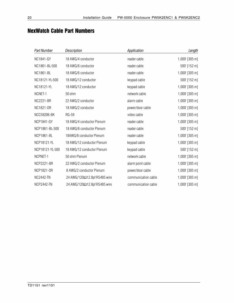
NexWatch Cable Part Numbers
Part Number Description Application Length
NC1841-GY 18 AWG/4 conductor reader cable 1,000' [305 m]
NC1861-BL-500 18 AWG/6 conductor reader cable 500' [152 m]
NC1861-BL 18 AWG/6 conductor reader cable 1,000' [305 m]
NC18121-YL-500 18 AWG/12 conductor keypad cable 500' [152 m]
NC18121-YL 18 AWG/12 conductor keypad cable 1,000' [305 m]
NCNET-1 50 ohm network cable 1,000' [305 m]
NC2221-BR 22 AWG/2 conductor alarm cable 1,000' [305 m]
NC1821-OR 18 AWG/2 conductor power/door cable 1,000' [305 m]
NCC59206-BK RG-59 video cable 1,000' [305 m]
NCP1841-GY 18 AWG/4 conductor Plenum reader cable 1,000' [305 m]
NCP1861-BL-500 18 AWG/6 conductor Plenum reader cable 500' [152 m]
NCP1861-BL 18AWG/6 conductor Plenum reader cable 1,000' [305 m]
NCP18121-YL 18 AWG/12 conductor Plenum keypad cable 1,000' [305 m]
NCP18121-YL-500 18 AWG/12 conductor Plenum keypad cable 500' [152 m]
NCPNET-1 50 ohm Plenum network cable 1,000' [305 m]
NCP2221-BR 22 AWG/2 conductor Plenum alarm point cable 1,000' [305 m]
NCP1821-OR 8 AWG/2 conductor Plenum power/door cable 1,000' [305 m]
NC2442-TN 24 AWG/120Ω12.8pf RS485 wire communication cable 1,000' [305 m]
NCP2442-TN 24 AWG/120Ω12.8pf RS485 wire communication cable 1,000' [305 m]

PW-5000 Enclosure PW5K2ENC1 & PW5K2ENC2 21Installation Guide
TD1151 rev1101
NOTES

Your Access to the Future47102 Mission Falls Court • Fremont, CA 94539 USA
Ph: (510) 360-7800 • Fax: (510) 360-7820www.nexwatch.com