Embed Size (px)
Citation preview
Partial StepPartial Step
OPERATOR’S MANUALOPERATOR’S MANUAL

NIDEK CO., LTD. : 34-14, Maehama, Hiroishi-cho, Gamagori, Aichi 443-0038, Japan(Manufacturer) Telephone: +81-533-67-6611
Facsimile: +81-533-67-6610NIDEK CO., LTD. : 3F Sumitomo Fudosan Hongo Bldg., 3-22-5, Hongo,(Tokyo Office) Bunkyo-Ku, Tokyo 113-0033, Japan
Telephone: +81-3-5844-2641Facsimile: +81-3-5844-2642
NIDEK INCORPORATED : 47651 Westinghouse Drive, Fremont, California 94539, U. S. A.(United States Agent) Telephone: +1-510-226-5700
Facsimile: +1-510-226-5750NIDEK S.A. : Europarc 13, rue Auguste Perret, 94042 Créteil, France(EU Authorized Representative) Telephone: +33-1-49 80 97 97
Facsimile: +33-1-49 80 32 08
February 201244630-P902A
Printed in Japan
Original instructions
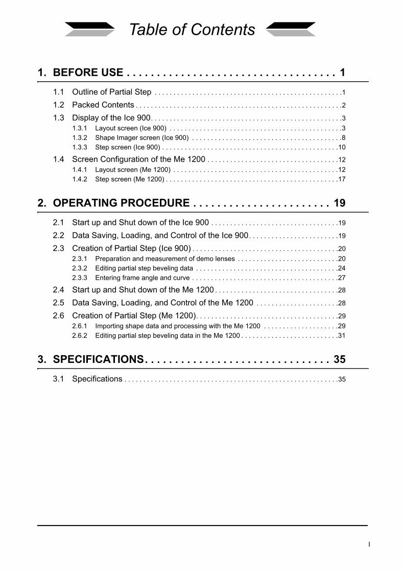
Table of Contents
1. BEFORE USE . . . . . . . . . . . . . . . . . . . . . . . . . . . . . . . . . . . 11.1 Outline of Partial Step . . . . . . . . . . . . . . . . . . . . . . . . . . . . . . . . . . . . . . . . . . . . . . . . . .1
1.2 Packed Contents . . . . . . . . . . . . . . . . . . . . . . . . . . . . . . . . . . . . . . . . . . . . . . . . . . . . . . .2
1.3 Display of the Ice 900. . . . . . . . . . . . . . . . . . . . . . . . . . . . . . . . . . . . . . . . . . . . . . . . . . .31.3.1 Layout screen (Ice 900) . . . . . . . . . . . . . . . . . . . . . . . . . . . . . . . . . . . . . . . . . . . . . .31.3.2 Shape Imager screen (Ice 900) . . . . . . . . . . . . . . . . . . . . . . . . . . . . . . . . . . . . . . . .81.3.3 Step screen (Ice 900) . . . . . . . . . . . . . . . . . . . . . . . . . . . . . . . . . . . . . . . . . . . . . . .10
1.4 Screen Configuration of the Me 1200 . . . . . . . . . . . . . . . . . . . . . . . . . . . . . . . . . . .121.4.1 Layout screen (Me 1200) . . . . . . . . . . . . . . . . . . . . . . . . . . . . . . . . . . . . . . . . . . . .121.4.2 Step screen (Me 1200) . . . . . . . . . . . . . . . . . . . . . . . . . . . . . . . . . . . . . . . . . . . . . .17
2. OPERATING PROCEDURE . . . . . . . . . . . . . . . . . . . . . . . 192.1 Start up and Shut down of the Ice 900 . . . . . . . . . . . . . . . . . . . . . . . . . . . . . . . . . .19
2.2 Data Saving, Loading, and Control of the Ice 900. . . . . . . . . . . . . . . . . . . . . . . .19
2.3 Creation of Partial Step (Ice 900) . . . . . . . . . . . . . . . . . . . . . . . . . . . . . . . . . . . . . . .202.3.1 Preparation and measurement of demo lenses . . . . . . . . . . . . . . . . . . . . . . . . . . .202.3.2 Editing partial step beveling data . . . . . . . . . . . . . . . . . . . . . . . . . . . . . . . . . . . . . .242.3.3 Entering frame angle and curve . . . . . . . . . . . . . . . . . . . . . . . . . . . . . . . . . . . . . . .27
2.4 Start up and Shut down of the Me 1200 . . . . . . . . . . . . . . . . . . . . . . . . . . . . . . . . .28
2.5 Data Saving, Loading, and Control of the Me 1200 . . . . . . . . . . . . . . . . . . . . . .28
2.6 Creation of Partial Step (Me 1200). . . . . . . . . . . . . . . . . . . . . . . . . . . . . . . . . . . . . .292.6.1 Importing shape data and processing with the Me 1200 . . . . . . . . . . . . . . . . . . . .292.6.2 Editing partial step beveling data in the Me 1200 . . . . . . . . . . . . . . . . . . . . . . . . . .31
3. SPECIFICATIONS. . . . . . . . . . . . . . . . . . . . . . . . . . . . . . . 353.1 Specifications . . . . . . . . . . . . . . . . . . . . . . . . . . . . . . . . . . . . . . . . . . . . . . . . . . . . . . . . .35
I

:
II
1. BEFORE USE
1
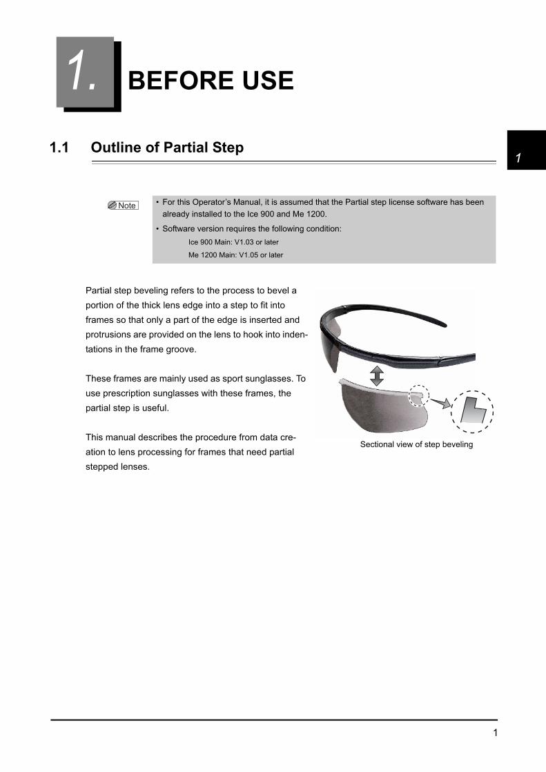
1.1 Outline of Partial StepPartial step beveling refers to the process to bevel a portion of the thick lens edge into a step to fit into frames so that only a part of the edge is inserted and protrusions are provided on the lens to hook into inden-tations in the frame groove.
These frames are mainly used as sport sunglasses. To use prescription sunglasses with these frames, the partial step is useful.
This manual describes the procedure from data cre-ation to lens processing for frames that need partial stepped lenses.
• For this Operator’s Manual, it is assumed that the Partial step license software has been already installed to the Ice 900 and Me 1200.
• Software version requires the following condition:Ice 900 Main: V1.03 or later
Me 1200 Main: V1.05 or later
Sectional view of step beveling
1
BEFORE USE: Packed Contents
1.2 Packed Contents
Unpack the contents from the shipping carton and check them.
The following are included in the standard configuration.
Kit for the Ice 900
Kit for the Me 1200
• Spatula 1 unit (44630-M111)
• Dust cover 1 unit (44630-M112)
• Specialized clay 1 unit (44630-M113)
• Operator’s Manual 1 volume (44630-P902)
• Operator’s Manual 1 volume (44630-P902)
2
BEFORE USE: Display of the Ice 900
1
1.3 Display of the Ice 900
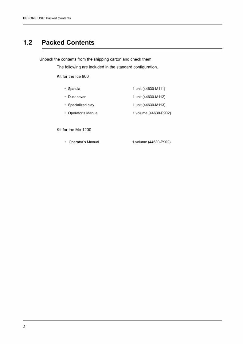
1.3.1 Layout screen (Ice 900)Screen for entering each data of lens layout and processing conditions with the Ice 900.
• The illustration of the lens in the screen display is as viewed from the front side in the right figure.
• Viewed from the front the lenses are mirrored so that the (R) lens is displayed on the left and the (L) lens is on the right.
12
3
56
4
7
8
9
10
11
12
13
14
15
16
17
18
19
20
21
2223
24
2526
27
Rear
Front
Right side (R)
Left side (L)
3
BEFORE USE: Display of the Ice 900
1. Right or Left buttonSpecifies whether the lens is right (R) or left (L).
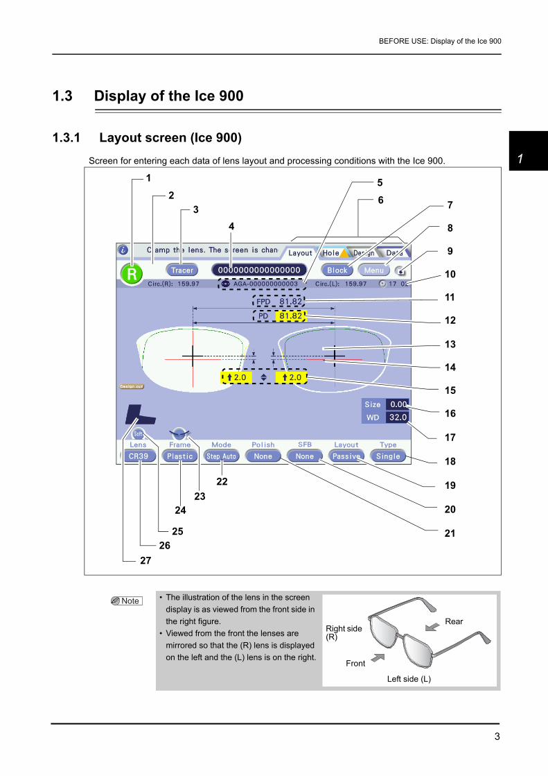
2. Shape R/L switching buttonAfter measuring the shape or tracing the pattern (demo lens), the Shape R/L switching button is displayed on the Layout screen.When this button is pressed, a confirmation message asking whether to switch the shape between Right and Left is displayed. Pressing the “Yes” button switches the shape between Right and Left.
After the shape is switched, the Shape R/L switching button disappears. This function is used when the measured or traced side (R or L) of the demo lens or pattern was not the side intended.
3. Tracer buttonLoads the shape data measured with the tracing unit to the display panel.
This button is displayed only when the Mini Lab system is set.
4. JOB#/PTN#Opens the keyboard screen to save and load the data.
In addition to the keyboard screen, JOB# (PTN#) can be entered by an optional barcode scanner.
5. PTN No. displayWhen the PTN data is saved or saved PTN data is loaded, the PTN number is displayed.
6. Screen change tabsChanges the screen from among the Layout screen, Hole Editor screen, Shape Editor screen, and Data Management screen.
• When no shape is displayed on the Layout screen, the button is notdisplayed when the keyboard screen is opened.
Shape R/L switching button
Shape switches between Right and Left.
4
BEFORE USE: Display of the Ice 900
1
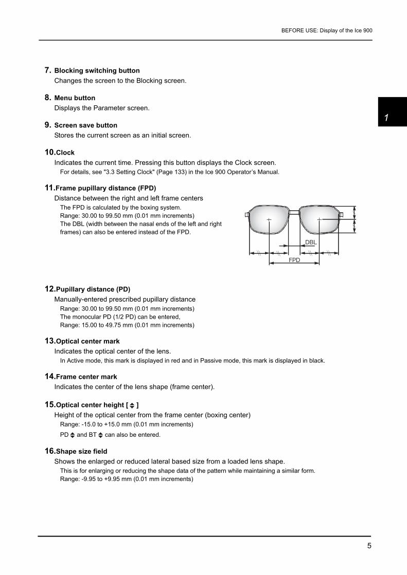
7. Blocking switching buttonChanges the screen to the Blocking screen.
8. Menu buttonDisplays the Parameter screen.
9. Screen save buttonStores the current screen as an initial screen.
10.ClockIndicates the current time. Pressing this button displays the Clock screen.
For details, see "3.3 Setting Clock" (Page 133) in the Ice 900 Operator’s Manual.
11.Frame pupillary distance (FPD)Distance between the right and left frame centers
The FPD is calculated by the boxing system.Range: 30.00 to 99.50 mm (0.01 mm increments)The DBL (width between the nasal ends of the left and right frames) can also be entered instead of the FPD.
12.Pupillary distance (PD)Manually-entered prescribed pupillary distance
Range: 30.00 to 99.50 mm (0.01 mm increments)The monocular PD (1/2 PD) can be entered,Range: 15.00 to 49.75 mm (0.01 mm increments)
13.Optical center markIndicates the optical center of the lens.
In Active mode, this mark is displayed in red and in Passive mode, this mark is displayed in black.
14.Frame center markIndicates the center of the lens shape (frame center).
15.Optical center height [ ]Height of the optical center from the frame center (boxing center)
Range: -15.0 to +15.0 mm (0.01 mm increments)
PD and BT can also be entered.
16.Shape size fieldShows the enlarged or reduced lateral based size from a loaded lens shape.
This is for enlarging or reducing the shape data of the pattern while maintaining a similar form.Range: -9.95 to +9.95 mm (0.01 mm increments)
5
BEFORE USE: Display of the Ice 900
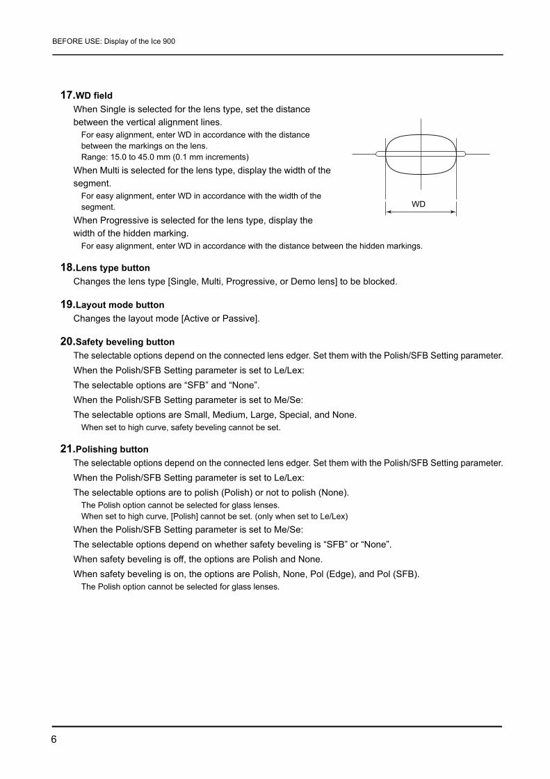
17.WD fieldWhen Single is selected for the lens type, set the distance between the vertical alignment lines.
For easy alignment, enter WD in accordance with the distance between the markings on the lens.Range: 15.0 to 45.0 mm (0.1 mm increments)
When Multi is selected for the lens type, display the width of the segment.
For easy alignment, enter WD in accordance with the width of the segment.
When Progressive is selected for the lens type, display the width of the hidden marking.
For easy alignment, enter WD in accordance with the distance between the hidden markings.
18.Lens type buttonChanges the lens type [Single, Multi, Progressive, or Demo lens] to be blocked.
19.Layout mode buttonChanges the layout mode [Active or Passive].
20.Safety beveling buttonThe selectable options depend on the connected lens edger. Set them with the Polish/SFB Setting parameter.When the Polish/SFB Setting parameter is set to Le/Lex:The selectable options are “SFB” and “None”.When the Polish/SFB Setting parameter is set to Me/Se:The selectable options are Small, Medium, Large, Special, and None.
When set to high curve, safety beveling cannot be set.
21.Polishing buttonThe selectable options depend on the connected lens edger. Set them with the Polish/SFB Setting parameter.When the Polish/SFB Setting parameter is set to Le/Lex:The selectable options are to polish (Polish) or not to polish (None).
The Polish option cannot be selected for glass lenses.When set to high curve, [Polish] cannot be set. (only when set to Le/Lex)
When the Polish/SFB Setting parameter is set to Me/Se:The selectable options depend on whether safety beveling is “SFB” or “None”.When safety beveling is off, the options are Polish and None.When safety beveling is on, the options are Polish, None, Pol (Edge), and Pol (SFB).
The Polish option cannot be selected for glass lenses.
WD
6
BEFORE USE: Display of the Ice 900
1
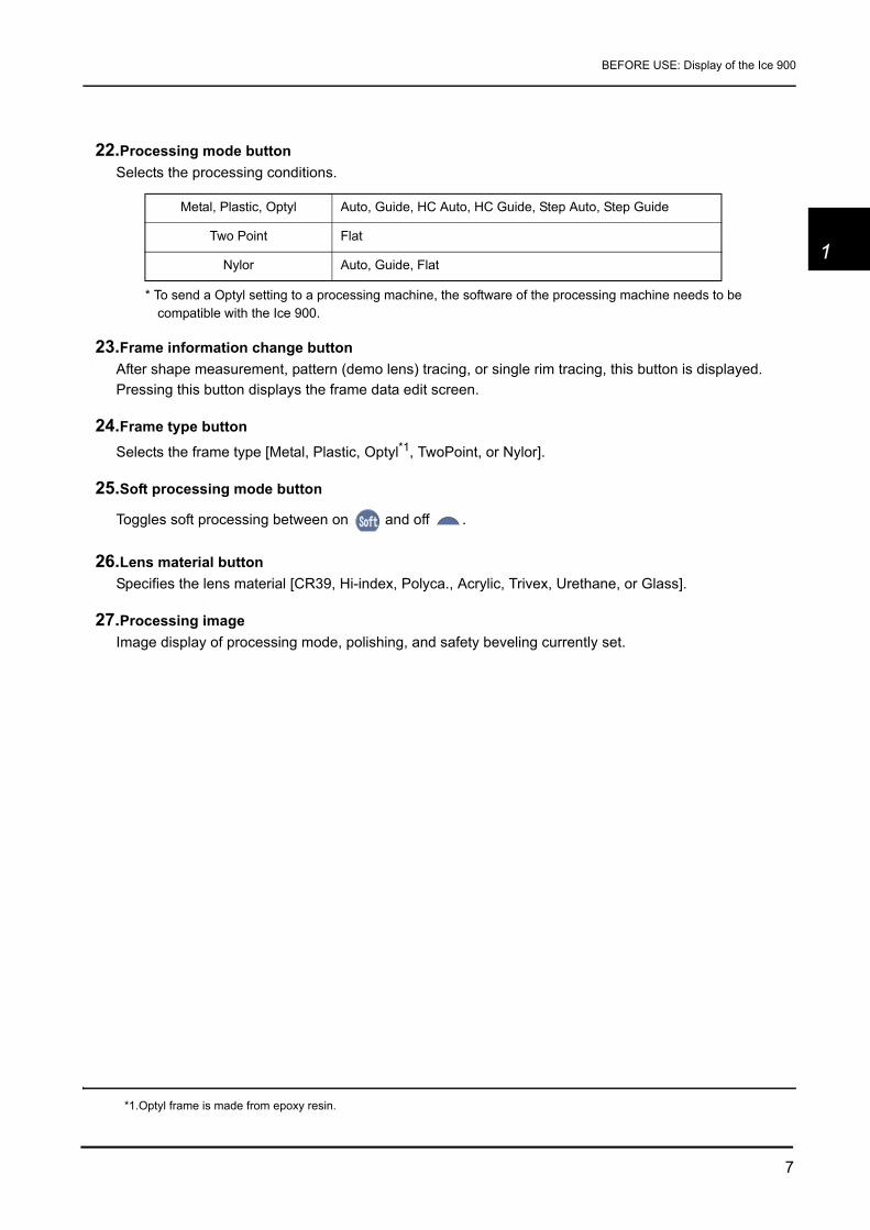
22.Processing mode buttonSelects the processing conditions.
* To send a Optyl setting to a processing machine, the software of the processing machine needs to be compatible with the Ice 900.
23.Frame information change buttonAfter shape measurement, pattern (demo lens) tracing, or single rim tracing, this button is displayed. Pressing this button displays the frame data edit screen.
24.Frame type button
Selects the frame type [Metal, Plastic, Optyl*1, TwoPoint, or Nylor].
25.Soft processing mode button
Toggles soft processing between on and off .
26.Lens material buttonSpecifies the lens material [CR39, Hi-index, Polyca., Acrylic, Trivex, Urethane, or Glass].
27.Processing imageImage display of processing mode, polishing, and safety beveling currently set.
Metal, Plastic, Optyl Auto, Guide, HC Auto, HC Guide, Step Auto, Step Guide
Two Point Flat
Nylor Auto, Guide, Flat
*1.Optyl frame is made from epoxy resin.
7
BEFORE USE: Display of the Ice 900
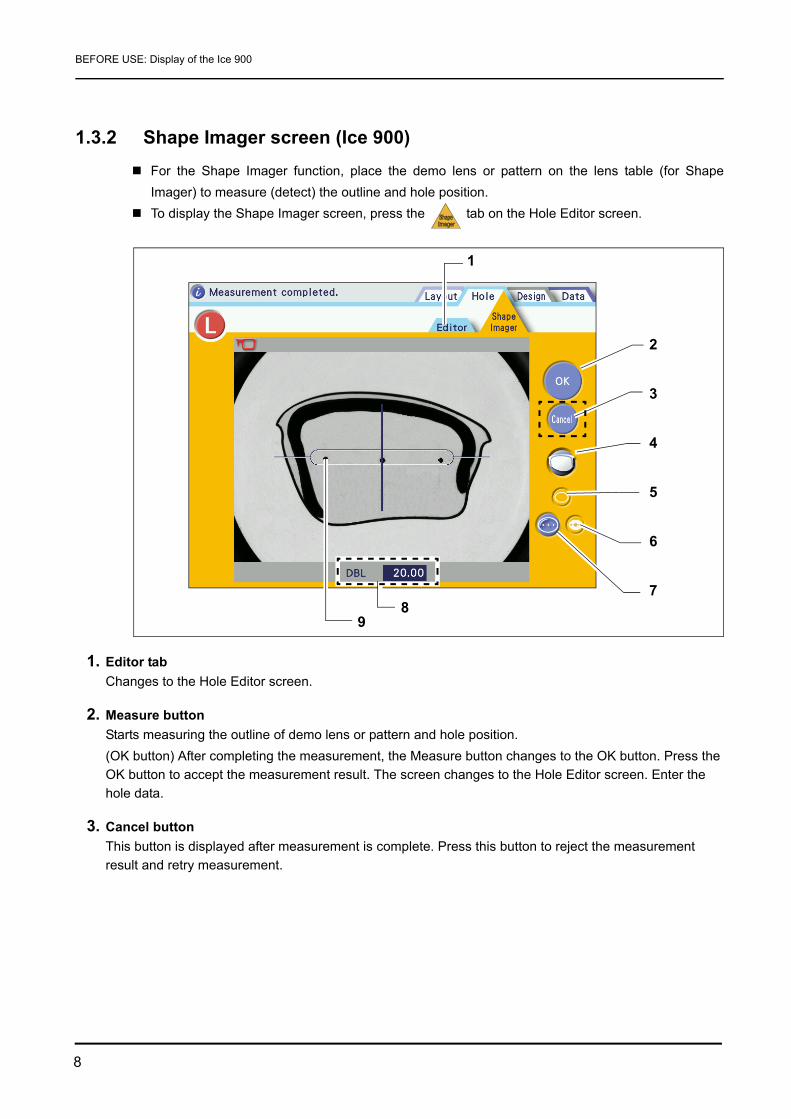
1.3.2 Shape Imager screen (Ice 900)For the Shape Imager function, place the demo lens or pattern on the lens table (for ShapeImager) to measure (detect) the outline and hole position.To display the Shape Imager screen, press the tab on the Hole Editor screen.
1. Editor tabChanges to the Hole Editor screen.
2. Measure buttonStarts measuring the outline of demo lens or pattern and hole position.(OK button) After completing the measurement, the Measure button changes to the OK button. Press the OK button to accept the measurement result. The screen changes to the Hole Editor screen. Enter the hole data.
3. Cancel buttonThis button is displayed after measurement is complete. Press this button to reject the measurement result and retry measurement.
1
2
3
4
5
6
78
9
8
BEFORE USE: Display of the Ice 900
1
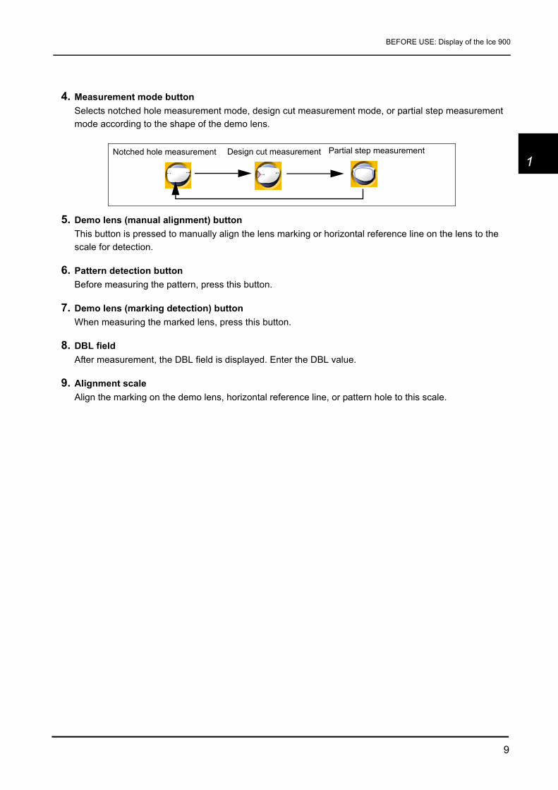
4. Measurement mode buttonSelects notched hole measurement mode, design cut measurement mode, or partial step measurement mode according to the shape of the demo lens.
5. Demo lens (manual alignment) buttonThis button is pressed to manually align the lens marking or horizontal reference line on the lens to the scale for detection.
6. Pattern detection buttonBefore measuring the pattern, press this button.
7. Demo lens (marking detection) buttonWhen measuring the marked lens, press this button.
8. DBL fieldAfter measurement, the DBL field is displayed. Enter the DBL value.
9. Alignment scaleAlign the marking on the demo lens, horizontal reference line, or pattern hole to this scale.
Notched hole measurement Design cut measurement Partial step measurement
9
BEFORE USE: Display of the Ice 900
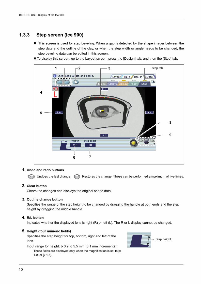
1.3.3 Step screen (Ice 900)This screen is used for step beveling. When a gap is detected by the shape imager between thestep data and the outline of the clay, or when the step width or angle needs to be changed, thestep beveling data can be edited in this screen.
To display this screen, go to the Layout screen, press the [Design] tab, and then the [Step] tab.
1. Undo and redo buttons
Undoes the last change. Restores the change. These can be performed a maximum of five times.
2. Clear buttonClears the changes and displays the original shape data.
3. Outline change buttonSpecifies the range of the step height to be changed by dragging the handle at both ends and the step height by dragging the middle handle.
4. R/L buttonIndicates whether the displayed lens is right (R) or left (L). The R or L display cannot be changed.
5. Height (four numeric fields)Specifies the step height for top, bottom, right and left of the lens.Input range for height: [- 0.2 to 5.5 mm (0.1 mm increments)]
These fields are displayed only when the magnification is set to [x 1.0] or [x 1.5].
3
8
9
76
Step tab
4
5
21
Step height
10
BEFORE USE: Display of the Ice 900
1
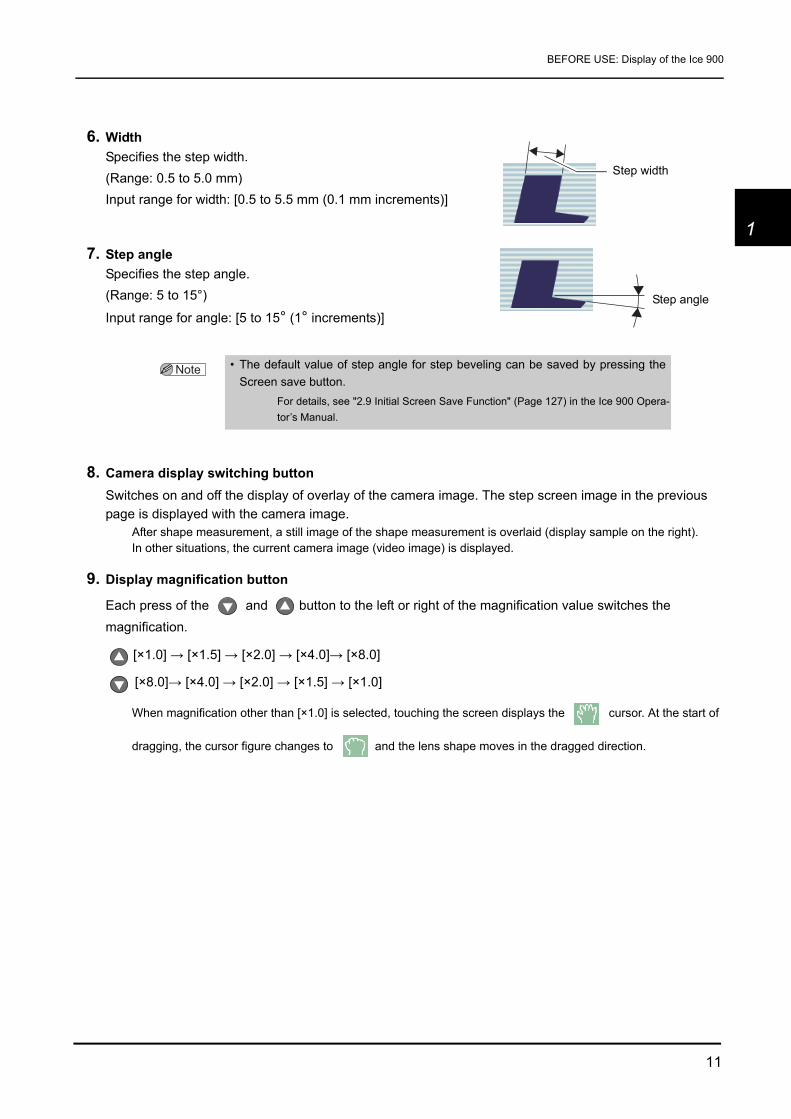
6. WidthSpecifies the step width.(Range: 0.5 to 5.0 mm)Input range for width: [0.5 to 5.5 mm (0.1 mm increments)]
7. Step angleSpecifies the step angle.(Range: 5 to 15°)
Input range for angle: [5 to 15° (1° increments)]
8. Camera display switching buttonSwitches on and off the display of overlay of the camera image. The step screen image in the previous page is displayed with the camera image.
After shape measurement, a still image of the shape measurement is overlaid (display sample on the right).In other situations, the current camera image (video image) is displayed.
9. Display magnification button
Each press of the and button to the left or right of the magnification value switches the magnification.
[×1.0] → [×1.5] → [×2.0] → [×4.0]→ [×8.0]
[×8.0]→ [×4.0] → [×2.0] → [×1.5] → [×1.0]
When magnification other than [×1.0] is selected, touching the screen displays the cursor. At the start of
dragging, the cursor figure changes to and the lens shape moves in the dragged direction.
• The default value of step angle for step beveling can be saved by pressing theScreen save button.
For details, see "2.9 Initial Screen Save Function" (Page 127) in the Ice 900 Opera-tor’s Manual.
Step width
Step angle
11
BEFORE USE: Screen Configuration of the Me 1200
1.4 Screen Configuration of the Me 1200
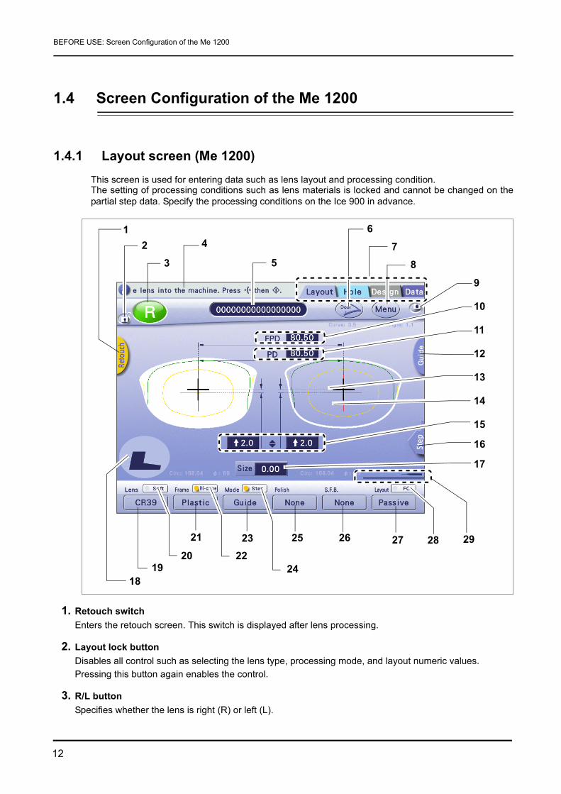
1.4.1 Layout screen (Me 1200)This screen is used for entering data such as lens layout and processing condition.The setting of processing conditions such as lens materials is locked and cannot be changed on thepartial step data. Specify the processing conditions on the Ice 900 in advance.
1. Retouch switchEnters the retouch screen. This switch is displayed after lens processing.
2. Layout lock buttonDisables all control such as selecting the lens type, processing mode, and layout numeric values. Pressing this button again enables the control.
3. R/L buttonSpecifies whether the lens is right (R) or left (L).
21
2220
12
1918
3 5
67
9
10
11
12
13
14
15
16
17
23
24
25 26 27 28
8
4
29
12
BEFORE USE: Screen Configuration of the Me 1200
1
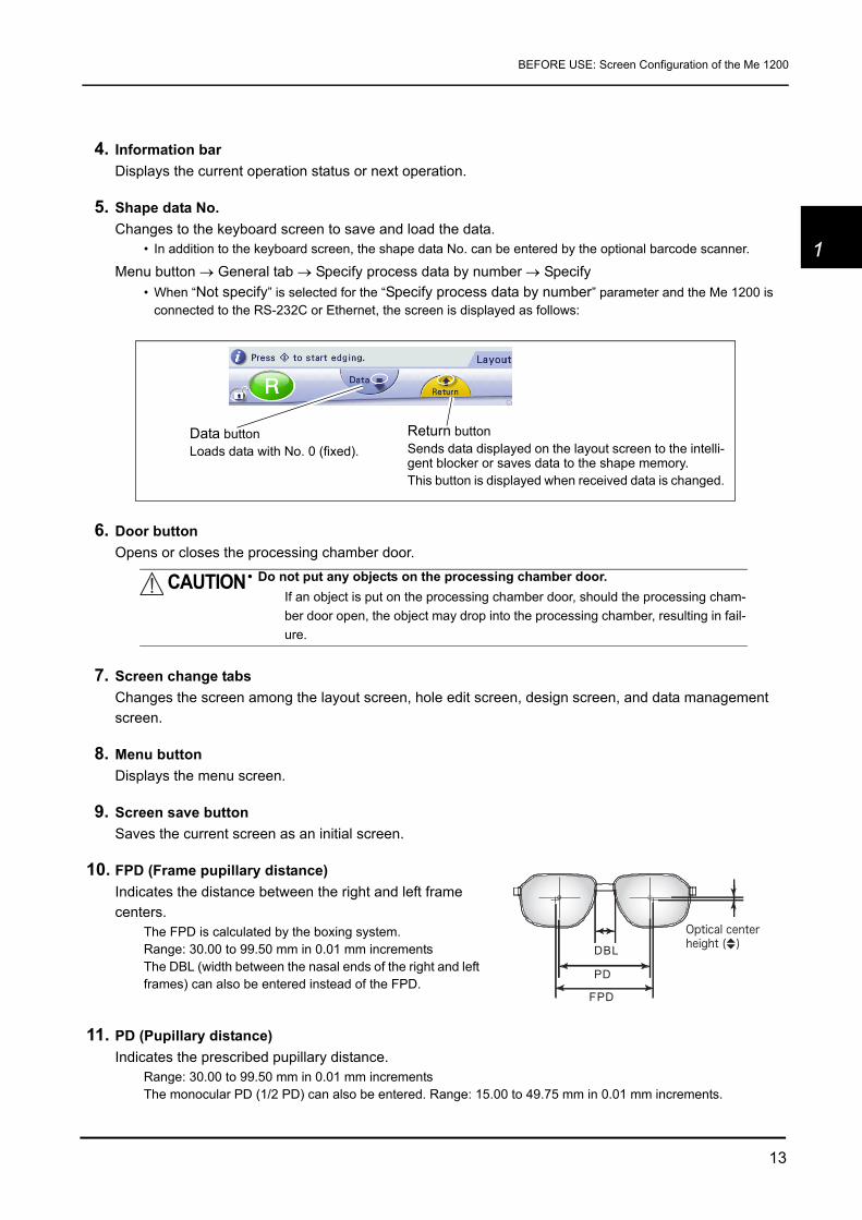
4. Information barDisplays the current operation status or next operation.
5. Shape data No.Changes to the keyboard screen to save and load the data.
• In addition to the keyboard screen, the shape data No. can be entered by the optional barcode scanner.
Menu button → General tab → Specify process data by number → Specify• When “Not specify” is selected for the “Specify process data by number” parameter and the Me 1200 is
connected to the RS-232C or Ethernet, the screen is displayed as follows:
6. Door buttonOpens or closes the processing chamber door.
7. Screen change tabsChanges the screen among the layout screen, hole edit screen, design screen, and data management screen.
8. Menu buttonDisplays the menu screen.
9. Screen save buttonSaves the current screen as an initial screen.
10. FPD (Frame pupillary distance)Indicates the distance between the right and left frame centers.
The FPD is calculated by the boxing system.Range: 30.00 to 99.50 mm in 0.01 mm incrementsThe DBL (width between the nasal ends of the right and left frames) can also be entered instead of the FPD.
11. PD (Pupillary distance)Indicates the prescribed pupillary distance.
Range: 30.00 to 99.50 mm in 0.01 mm incrementsThe monocular PD (1/2 PD) can also be entered. Range: 15.00 to 49.75 mm in 0.01 mm increments.
Data buttonLoads data with No. 0 (fixed).
Return buttonSends data displayed on the layout screen to the intelli-gent blocker or saves data to the shape memory.This button is displayed when received data is changed.
CAUTION• Do not put any objects on the processing chamber door.If an object is put on the processing chamber door, should the processing cham-ber door open, the object may drop into the processing chamber, resulting in fail-ure.
P D
F P D
D B L
13
BEFORE USE: Screen Configuration of the Me 1200
12. Guide switchChanges the screen to the simulation screen. This switch is displayed after lens processing.
13. Optical center markIndicates the optical center of the lens.
In active mode, displayed in red and in passive mode, displayed in black.
14. Frame center markIndicates the center of the lens shape (frame center).
15. Optical center height ( )Indicates the height of the optical center from the frame center (boxing center).
Range: -15.0 to 15.0 mm in 0.1 mm increments
When the field is pressed, the indication changes in the order of → PD → BT → .
16. Step switchChanges the screen to the step screen. This switch is displayed only when the Layout button is set to Passive and the Hi-curve and Step buttons are turned on.
17. SizeShows the enlarged or reduced lateral based size from a loaded lens shape.
Enter a compensation value for the lens finish diameter in reference (0.00) to the frame diameter.Range: -9.95 to 9.95 mm in 0.01 mm increments
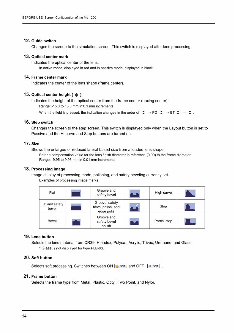
18. Processing imageImage display of processing mode, polishing, and safety beveling currently set.
Examples of processing image marks
19. Lens buttonSelects the lens material from CR39, Hi-index, Polyca., Acrylic, Trivex, Urethane, and Glass.
* Glass is not displayed for type PLB-8S.
20. Soft button
Selects soft processing. Switches between ON and OFF .
21. Frame buttonSelects the frame type from Metal, Plastic, Optyl, Two Point, and Nylor.
Flat Groove and safety bevel High curve
Flat and safety bevel
Groove, safety bevel polish, and
edge polisStep
BevelGroove and safety bevel
polishPartial step
SoftSoft SoftSoft
14
BEFORE USE: Screen Configuration of the Me 1200
1
22. Hi-curve button
Selects high base curve processing. Switches between ON and OFF .
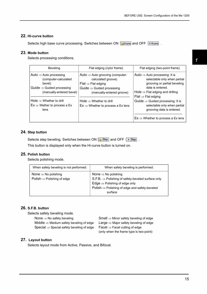
23. Mode buttonSelects processing conditions.
24. Step button
Selects step beveling. Switches between ON and OFF .
This button is displayed only when the Hi-curve button is turned on.
25. Polish buttonSelects polishing mode.
26. S.F.B. buttonSelects safety beveling mode.
None ⇒ No safety beveling Small ⇒ Minor safety beveling of edgeMiddle ⇒ Medium safety beveling of edge Large ⇒ Major safety beveling of edgeSpecial ⇒ Special safety beveling of edge Facet ⇒ Facet cutting of edge
(only when the frame type is two-point)
27. Layout buttonSelects layout mode from Active, Passive, and Bifocal.
Beveling Flat edging (nylor frame) Flat edging (two-point frame)
Auto ⇒ Auto processing (computer-calculated bevel)
Guide ⇒ Guided processing (manually-entered bevel)
-------------------------------------------Hole ⇒ Whether to drillEx ⇒ Wether to process a Ex
lens
Auto ⇒ Auto grooving (computer-calculated groove)
Flat ⇒ Flat edgingGuide ⇒ Guided processing
(manually-entered groove)------------------------------------------------Hole ⇒ Whether to drillEx ⇒ Whether to process a Ex lens
Auto ⇒ Auto processing: It is selectable only when partial grooving or partial beveling data is entered.
Hole ⇒ Flat edging and drillingFlat ⇒ Flat edgingGuide ⇒ Guided processing: It is
selectable only when partial grooving data is entered.
----------------------------------------------Ex ⇒ Whether to process a Ex lens
Hi-curveHi-curve Hi-curveHi-curve
StepStep StepStep
When safety beveling is not performed: When safety beveling is performed:
None ⇒ No polishingPolish ⇒ Polishing of edge
None ⇒ No polishingS.F.B. ⇒ Polishing of safety-beveled surface onlyEdge ⇒ Polishing of edge onlyPolish ⇒ Polishing of edge and safety-beveled
surface
15
BEFORE USE: Screen Configuration of the Me 1200
28. FC button
Selects frame changing mode. Switches between ON and OFF .
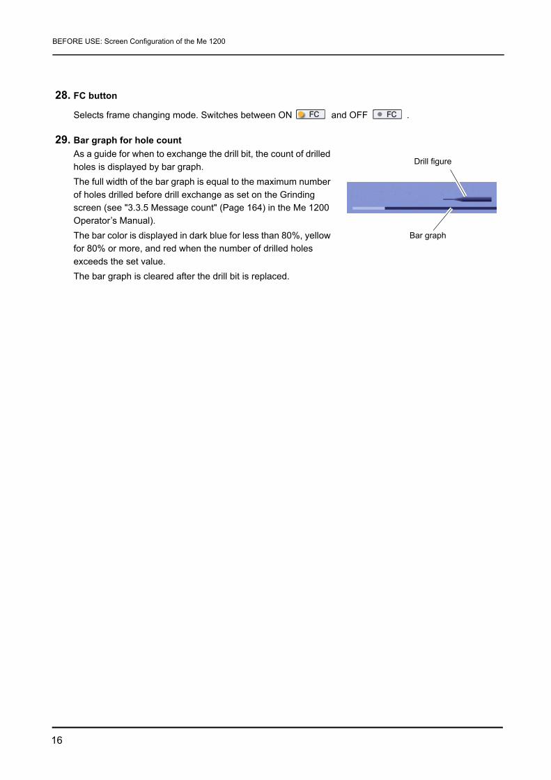
29. Bar graph for hole countAs a guide for when to exchange the drill bit, the count of drilled holes is displayed by bar graph.The full width of the bar graph is equal to the maximum number of holes drilled before drill exchange as set on the Grinding screen (see "3.3.5 Message count" (Page 164) in the Me 1200 Operator’s Manual).The bar color is displayed in dark blue for less than 80%, yellow for 80% or more, and red when the number of drilled holes exceeds the set value.The bar graph is cleared after the drill bit is replaced.
FCFC FCFC
Drill figure
Bar graph
16
BEFORE USE: Screen Configuration of the Me 1200
1
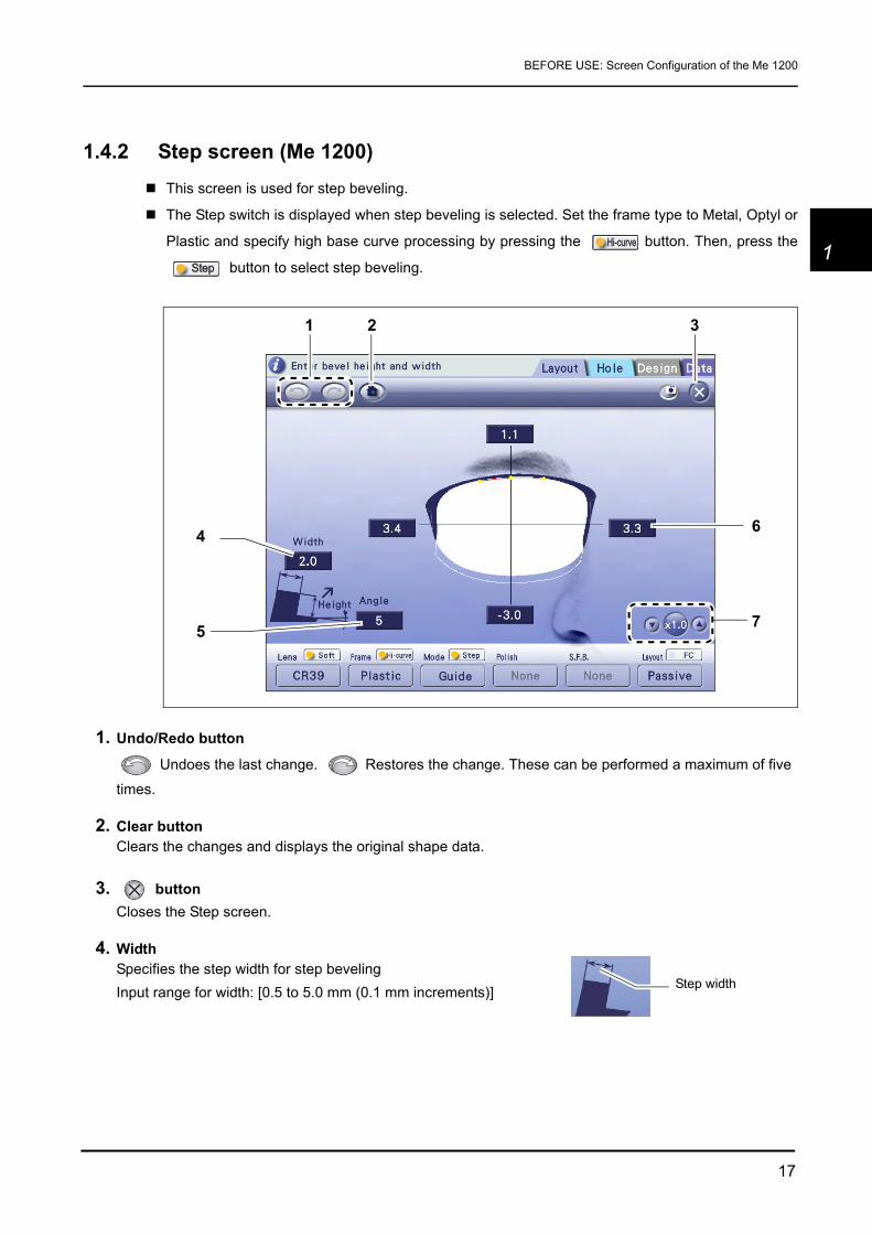
1.4.2 Step screen (Me 1200)This screen is used for step beveling.
The Step switch is displayed when step beveling is selected. Set the frame type to Metal, Optyl or
Plastic and specify high base curve processing by pressing the button. Then, press the
button to select step beveling.
1. Undo/Redo button
Undoes the last change. Restores the change. These can be performed a maximum of five
times.
2. Clear buttonClears the changes and displays the original shape data.
3. buttonCloses the Step screen.
4. WidthSpecifies the step width for step bevelingInput range for width: [0.5 to 5.0 mm (0.1 mm increments)]
Hi-curveHi-curve
StepStep
4
5
6
7
1 2 3
Step width
17
BEFORE USE: Screen Configuration of the Me 1200
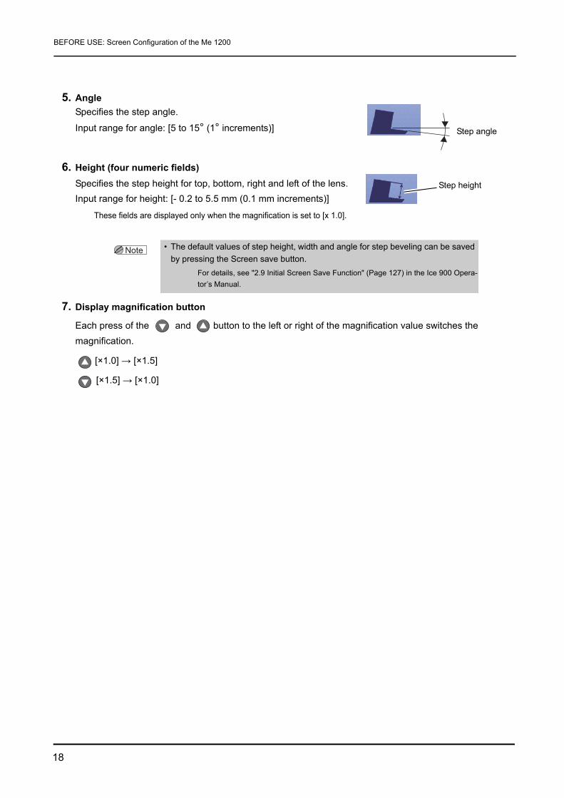
5. AngleSpecifies the step angle.
Input range for angle: [5 to 15° (1° increments)]
6. Height (four numeric fields)Specifies the step height for top, bottom, right and left of the lens.Input range for height: [- 0.2 to 5.5 mm (0.1 mm increments)]
These fields are displayed only when the magnification is set to [x 1.0].
7. Display magnification button
Each press of the and button to the left or right of the magnification value switches the magnification.
[×1.0] → [×1.5]
[×1.5] → [×1.0]
• The default values of step height, width and angle for step beveling can be savedby pressing the Screen save button.
For details, see "2.9 Initial Screen Save Function" (Page 127) in the Ice 900 Opera-tor’s Manual.
Step angle
Step height
18
2. OPERATING PROCEDURE
2
2.1 Start up and Shut down of the Ice 900
For getting started and exiting the Ice 900, refer to “2.2 Getting Started and Exiting (Page45)” in the Ice 900 Operator’s Manual.
2.2 Data Saving, Loading, and Control of the Ice 900
For saving, loading, or control data of the Ice 900, refer to “2.3 Data Saving, Loading, Con-trol (Page 46 to 56)” in the Ice 900 Operator’s Manual.
19
OPERATING PROCEDURE: Creation of Partial Step (Ice 900)
2.3 Creation of Partial Step (Ice 900)
2.3.1 Preparation and measurement of demo lenses
1 Remove the demo lens from the frame and clean up the lens.When the part of the demo lens that is inserted into a frame groove is dirty, the measure-ment may not be performed properly.
2 After attaching the demo lens to the frame, mark the demo lens with a lensmeter.Refer to “2.6.3 Preparation for demo lenses (Page 99)” in the Ice 900 Operator’s Manual.
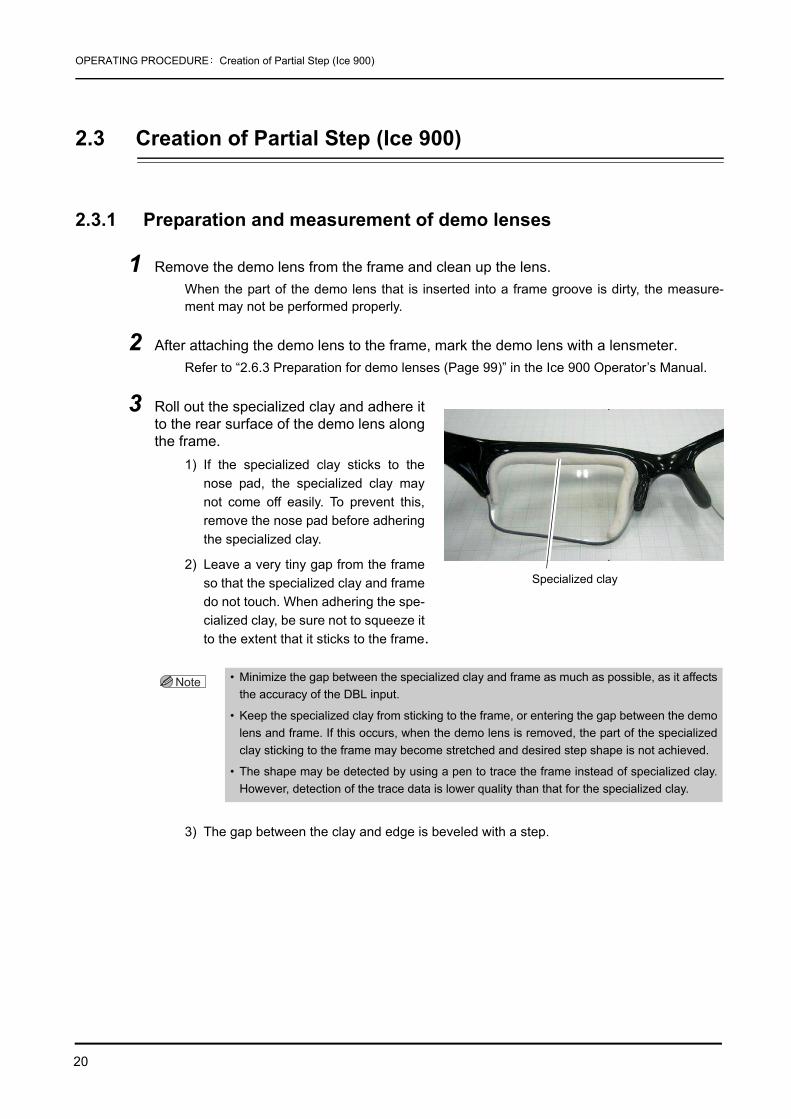
3 Roll out the specialized clay and adhere itto the rear surface of the demo lens alongthe frame.
1) If the specialized clay sticks to thenose pad, the specialized clay maynot come off easily. To prevent this,remove the nose pad before adheringthe specialized clay.
2) Leave a very tiny gap from the frameso that the specialized clay and framedo not touch. When adhering the spe-cialized clay, be sure not to squeeze itto the extent that it sticks to the frame.
3) The gap between the clay and edge is beveled with a step.
• Minimize the gap between the specialized clay and frame as much as possible, as it affectsthe accuracy of the DBL input.
• Keep the specialized clay from sticking to the frame, or entering the gap between the demolens and frame. If this occurs, when the demo lens is removed, the part of the specializedclay sticking to the frame may become stretched and desired step shape is not achieved.
• The shape may be detected by using a pen to trace the frame instead of specialized clay.However, detection of the trace data is lower quality than that for the specialized clay.
Specialized clay
20
OPERATING PROCEDURE: Creation of Partial Step (Ice 900)
2
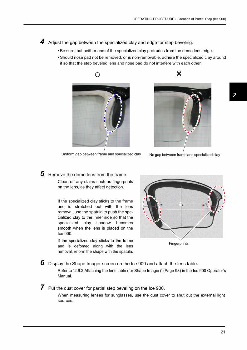
4 Adjust the gap between the specialized clay and edge for step beveling.
• Be sure that neither end of the specialized clay protrudes from the demo lens edge.• Should nose pad not be removed, or is non-removable, adhere the specialized clay around
it so that the step beveled lens and nose pad do not interfere with each other.
5 Remove the demo lens from the frame.Clean off any stains such as fingerprintson the lens, as they affect detection.
If the specialized clay sticks to the frameand is stretched out with the lensremoval, use the spatula to push the spe-cialized clay to the inner side so that thespecialized clay shadow becomessmooth when the lens is placed on theIce 900.
If the specialized clay sticks to the frameand is defomed along with the lensremoval, reform the shape with the spatula.
6 Display the Shape Imager screen on the Ice 900 and attach the lens table.Refer to “2.6.2 Attaching the lens table (for Shape Imager)” (Page 98) in the Ice 900 Operator’sManual.
7 Put the dust cover for partial step beveling on the Ice 900.When measuring lenses for sunglasses, use the dust cover to shut out the external lightsources.
Uniform gap between frame and specialized clay No gap between frame and specialized clay
○ ×
Fingerprints
21
OPERATING PROCEDURE: Creation of Partial Step (Ice 900)
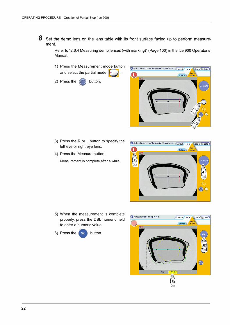
8 Set the demo lens on the lens table with its front surface facing up to perform measure-ment.
Refer to “2.6.4 Measuring demo lenses (with marking)” (Page 100) in the Ice 900 Operator’sManual.
1) Press the Measurement mode buttonand select the partial mode .
2) Press the button.
3) Press the R or L button to specify theleft eye or right eye lens.
4) Press the Measure button.
Measurement is complete after a while.
5) When the measurement is completeproperly, press the DBL numeric fieldto enter a numeric value.
6) Press the button.
1)1)
2)2)
3)3)
4)4)
6)6)
5)5)
OK
22
OPERATING PROCEDURE: Creation of Partial Step (Ice 900)
2
9 Remove the dust cover for partial step from the Ice 900 and finish the measurement.
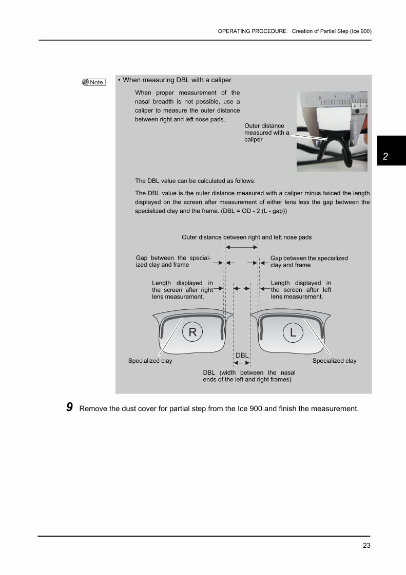
• When measuring DBL with a caliper
When proper measurement of thenasal breadth is not possible, use acaliper to measure the outer distancebetween right and left nose pads.
The DBL value can be calculated as follows:
The DBL value is the outer distance measured with a caliper minus twiced the lengthdisplayed on the screen after measurement of either lens less the gap between thespecialized clay and the frame. (DBL = OD - 2 (L - gap))
Outer distance measured with a caliper
LR
DBL
Outer distance between right and left nose pads
Length displayed inthe screen after rightlens measurement.
Length displayed inthe screen after leftlens measurement.
Gap between the special-ized clay and frame
Specialized clay
Gap between the specializedclay and frame
Specialized clay
DBL (width between the nasalends of the left and right frames)
23
OPERATING PROCEDURE: Creation of Partial Step (Ice 900)
2.3.2 Editing partial step beveling dataDisplay the Step screen to check the step data. When there is a gap between step data detected bythe shape imager and outline of the specialized clay, or when the step width and angle need to bechanged, the partial step data can be edited in this screen.
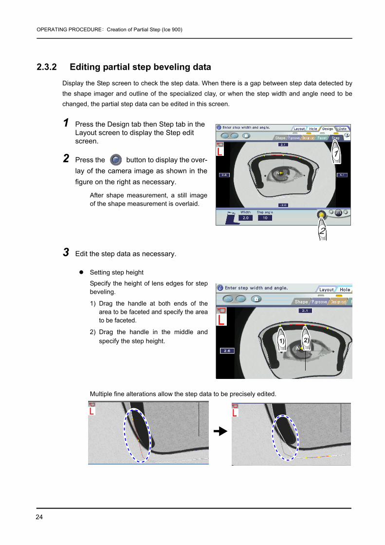
1 Press the Design tab then Step tab in the Layout screen to display the Step edit screen.
2 Press the button to display the over-lay of the camera image as shown in thefigure on the right as necessary.
After shape measurement, a still imageof the shape measurement is overlaid.
3 Edit the step data as necessary.
Setting step height
Specify the height of lens edges for stepbeveling.
1) Drag the handle at both ends of thearea to be faceted and specify the areato be faceted.
2) Drag the handle in the middle andspecify the step height.
Multiple fine alterations allow the step data to be precisely edited.
2
1
1)1) 2)2)
24
OPERATING PROCEDURE: Creation of Partial Step (Ice 900)
2
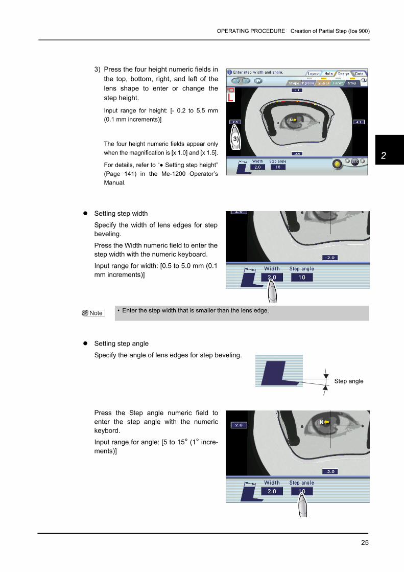
3) Press the four height numeric fields inthe top, bottom, right, and left of thelens shape to enter or change thestep height.
Input range for height: [- 0.2 to 5.5 mm(0.1 mm increments)]
The four height numeric fields appear onlywhen the magnification is [x 1.0] and [x 1.5].
For details, refer to “● Setting step height”(Page 141) in the Me-1200 Operator’sManual.
Setting step width
Specify the width of lens edges for stepbeveling.
Press the Width numeric field to enter thestep width with the numeric keyboard.
Input range for width: [0.5 to 5.0 mm (0.1mm increments)]
Setting step angle
Specify the angle of lens edges for step beveling.
Press the Step angle numeric field toenter the step angle with the numerickeybord.
Input range for angle: [5 to 15° (1° incre-ments)]
3)3)
• Enter the step width that is smaller than the lens edge.
Step angle
25
OPERATING PROCEDURE: Creation of Partial Step (Ice 900)
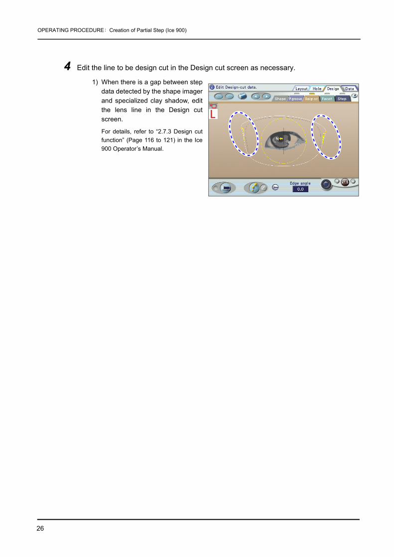
4 Edit the line to be design cut in the Design cut screen as necessary.
1) When there is a gap between stepdata detected by the shape imagerand specialized clay shadow, editthe lens line in the Design cutscreen.
For details, refer to “2.7.3 Design cutfunction” (Page 116 to 121) in the Ice900 Operator’s Manual.
26
OPERATING PROCEDURE: Creation of Partial Step (Ice 900)
2
2.3.3 Entering frame angle and curveWhen the frame angle and curve is forgotten to be entered, PD may not be correct after the processedlens is set to a frame. To correct the PD, enter a frame angle and curve.
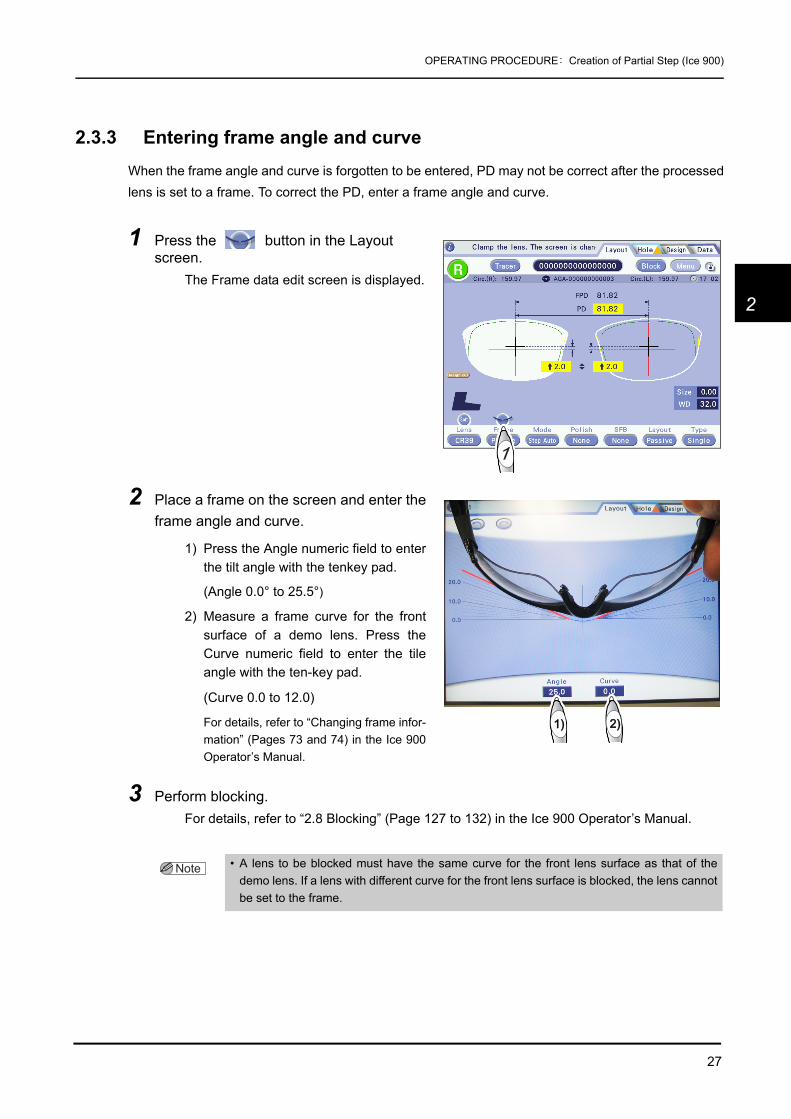
1 Press the button in the Layout screen.
The Frame data edit screen is displayed.
2 Place a frame on the screen and enter theframe angle and curve.
1) Press the Angle numeric field to enterthe tilt angle with the tenkey pad.
(Angle 0.0° to 25.5°)
2) Measure a frame curve for the frontsurface of a demo lens. Press theCurve numeric field to enter the tileangle with the ten-key pad.
(Curve 0.0 to 12.0)
For details, refer to “Changing frame infor-mation” (Pages 73 and 74) in the Ice 900Operator’s Manual.
3 Perform blocking.For details, refer to “2.8 Blocking” (Page 127 to 132) in the Ice 900 Operator’s Manual.
• A lens to be blocked must have the same curve for the front lens surface as that of thedemo lens. If a lens with different curve for the front lens surface is blocked, the lens cannotbe set to the frame.
1
1)1) 2)2)
27
OPERATING PROCEDURE: Start up and Shut down of the Me 1200
2.4 Start up and Shut down of the Me 1200
For starting and shutting down the Me 1200, refer to “2.2 Start and Shut Down” (Page 43and 44) in the Me 1200 Operator’s Manual.
2.5 Data Saving, Loading, and Control of the Me 1200
For managing, saving and loading data in the Me 1200, refer to “2.3 Managing, Saving andLoading Data” (Page 45 to 55) in the Me 1200 Operator’s Manual.
28
OPERATING PROCEDURE: Creation of Partial Step (Me 1200)
2
2.6 Creation of Partial Step (Me 1200)
The processing conditions such as lens material cannot be changed on the partial step data that hasbeen imported to the Me 1200. Specify the processing conditions on the Ice 900 in advance.When the layout values such as PD is imported with blank, the data can be input on the Me 1200.However, the layout values that are input on the Ice 900 cannot be changed on the Me 1200.
2.6.1 Importing shape data and processing with the Me 1200
1 Import blocked data from the Ice 900.For details, refer to “2.4 Importing Shape Data” (Page 56 to 59) in the Me 1200 Operator’s Manual.
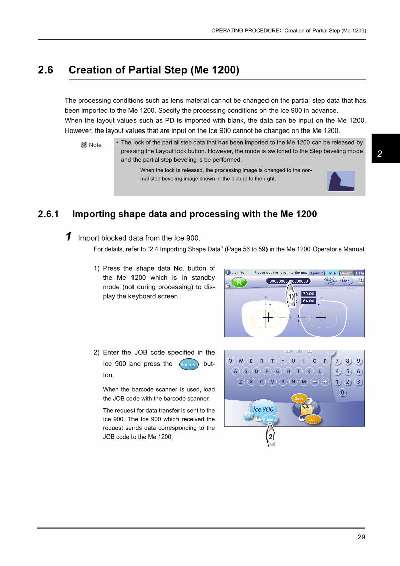
1) Press the shape data No. button ofthe Me 1200 which is in standbymode (not during processing) to dis-play the keyboard screen.
2) Enter the JOB code specified in the
Ice 900 and press the but-
ton.
When the barcode scanner is used, loadthe JOB code with the barcode scanner.
The request for data transfer is sent to theIce 900. The Ice 900 which received therequest sends data corresponding to theJOB code to the Me 1200.
• The lock of the partial step data that has been imported to the Me 1200 can be released bypressing the Layout lock button. However, the mode is switched to the Step beveling modeand the partial step beveling is be performed.
When the lock is released, the processing image is changed to the nor-mal step beveling image shown in the picture to the right.
1)1)
2)2)
29
OPERATING PROCEDURE: Creation of Partial Step (Me 1200)
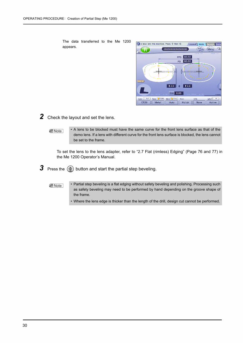
The data transferred to the Me 1200appears.
2 Check the layout and set the lens.
To set the lens to the lens adapter, refer to “2.7 Flat (rimless) Edging” (Page 76 and 77) inthe Me 1200 Operator’s Manual.
3 Press the button and start the partial step beveling.
• A lens to be blocked must have the same curve for the front lens surface as that of thedemo lens. If a lens with different curve for the front lens surface is blocked, the lens cannotbe set to the frame.
• Partial step beveling is a flat edging without safety beveling and polishing. Processing suchas safety beveling may need to be performed by hand depending on the groove shape ofthe frame.
• Where the lens edge is thicker than the length of the drill, design cut cannot be performed.
30
OPERATING PROCEDURE: Creation of Partial Step (Me 1200)
2
2.6.2 Editing partial step beveling data in the Me 1200Imported step beveling data can be edited in the Me 1200.For more details, refer to “2.13 Step Beveling (types PLB-8S and PLB-2R8S only)” (Page 140 and141) in the Me 1200 Operator’s Manual.
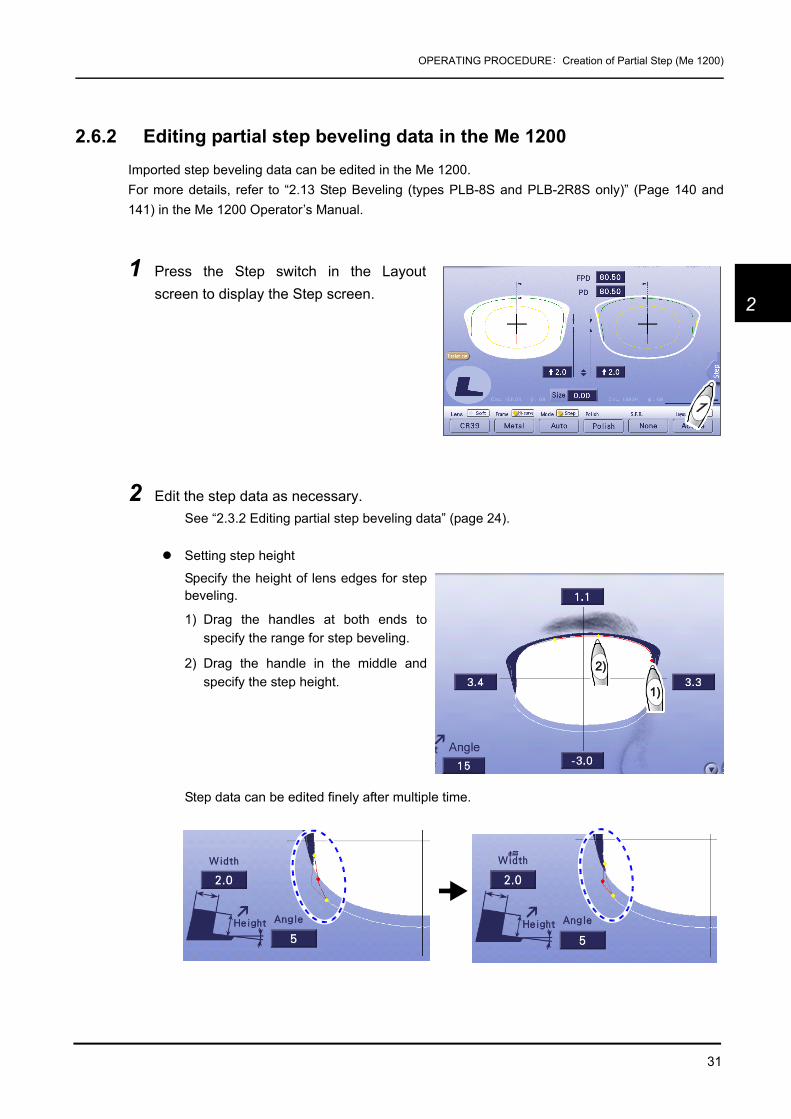
1 Press the Step switch in the Layoutscreen to display the Step screen.
2 Edit the step data as necessary.See “2.3.2 Editing partial step beveling data” (page 24).
Setting step height
Specify the height of lens edges for stepbeveling.
1) Drag the handles at both ends tospecify the range for step beveling.
2) Drag the handle in the middle andspecify the step height.
Step data can be edited finely after multiple time.
1
1)1)
2)2)
31
OPERATING PROCEDURE: Creation of Partial Step (Me 1200)
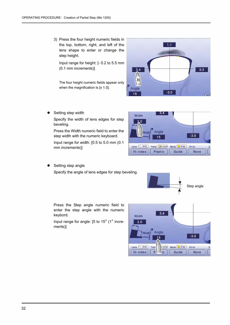
3) Press the four height numeric fields inthe top, bottom, right, and left of thelens shape to enter or change thestep height.
Input range for height: [- 0.2 to 5.5 mm(0.1 mm increments)]
The four height numeric fields appear onlywhen the magnification is [x 1.0].
Setting step width
Specify the width of lens edges for stepbeveling.
Press the Width numeric field to enter thestep width with the numeric keyboard.
Input range for width: [0.5 to 5.0 mm (0.1mm increments)]
Setting step angle
Specify the angle of lens edges for step beveling.
Press the Step angle numeric field toenter the step angle with the numerickeybord.
Input range for angle: [5 to 15° (1° incre-ments)]
3)3)
Step angle
32
OPERATING PROCEDURE: Creation of Partial Step (Me 1200)
2
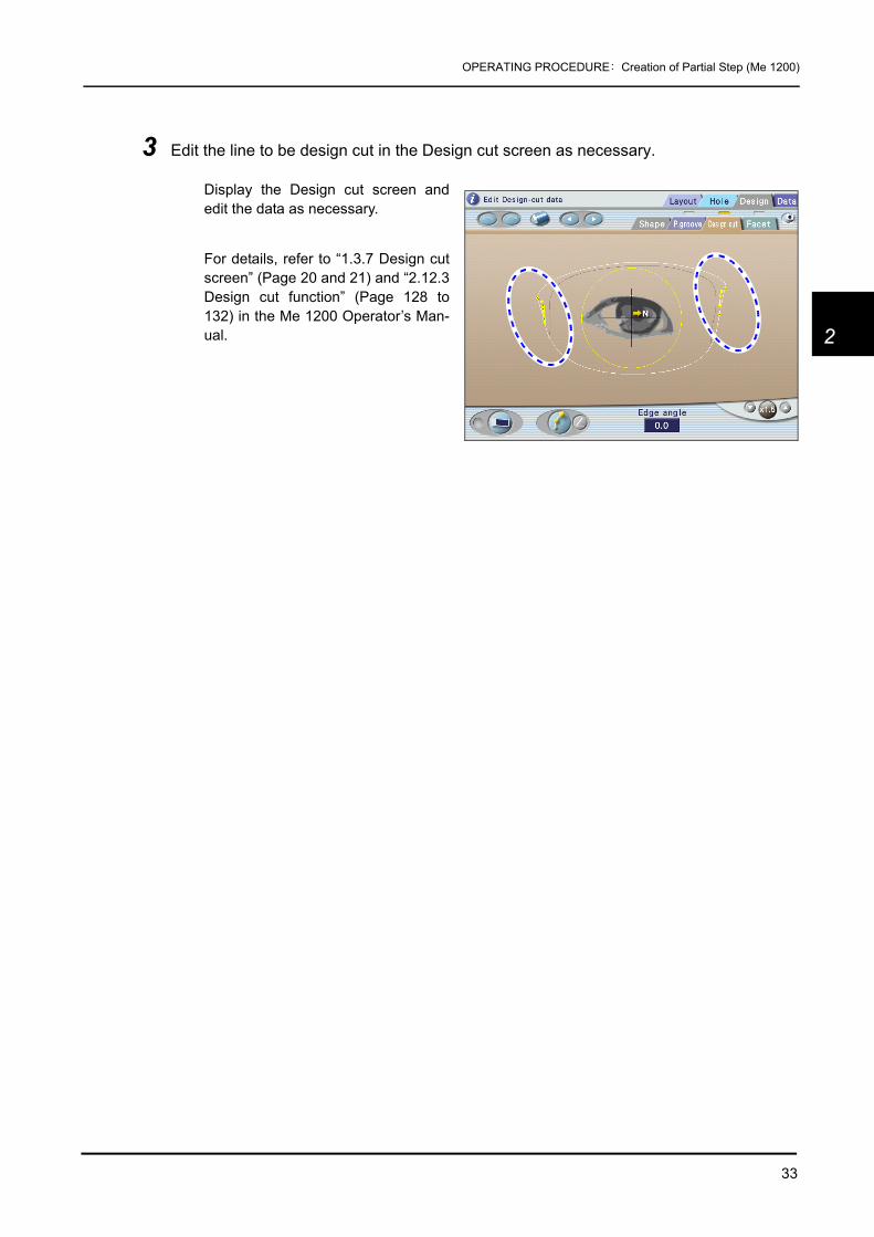
3 Edit the line to be design cut in the Design cut screen as necessary.
Display the Design cut screen andedit the data as necessary.
For details, refer to “1.3.7 Design cutscreen” (Page 20 and 21) and “2.12.3Design cut function” (Page 128 to132) in the Me 1200 Operator’s Man-ual.
33

OPERATING PROCEDURE: Creation of Partial Step (Me 1200)
34
3. SPECIFICATIONS
3
3.1 Specifications
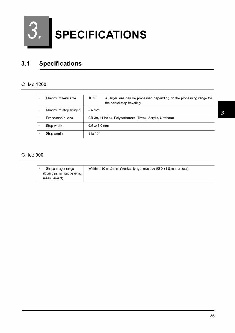
Me 1200
Ice 900
• Maximum lens size Ф70.5 A larger lens can be processed depending on the processing range forthe partial step beveling.
• Maximum step height 5.5 mm
• Processable lens CR-39, Hi-index, Polycarbonate, Trivex, Acrylic, Urethane
• Step width 0.5 to 5.0 mm
• Step angle 5 to 15°
• Shape imager range(During partial step bevelingmeasurement)
Within Ф80 ±1.5 mm (Vertical length must be 55.0 ±1.5 mm or less)
35

SPECIFICATIONS: Specifications
36