Embed Size (px)
Citation preview
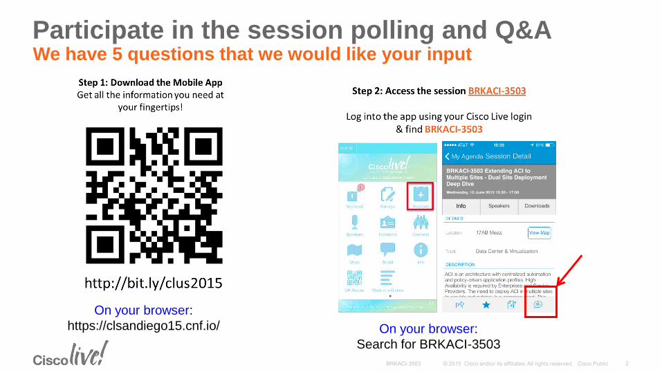
Participate in the session polling and Q&A We have 5 questions that we would like your input
On your browser:
https://clsandiego15.cnf.io/ On your browser:
Search for BRKACI-3503
Extending ACI to Multiple Sites Dual Site Deployment Deep Dive
Santiago Freitas ([email protected]), Customer Solutions Architect
Patrice Bellagamba ([email protected]), Distinguished Systems Engineer
BRKACI-3503
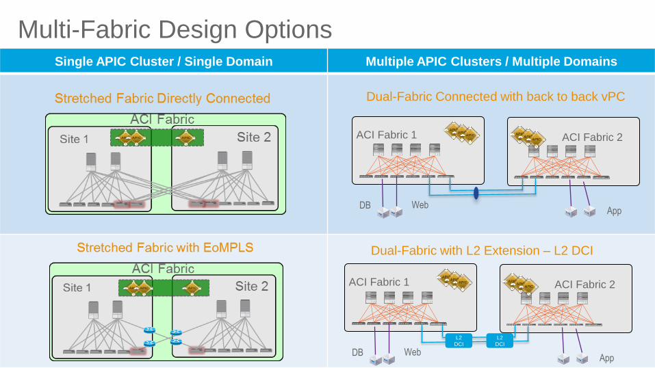
Multi-Fabric Design Options Single APIC Cluster / Single Domain Multiple APIC Clusters / Multiple Domains
ACI Fabric 2 ACI Fabric 1
Dual-Fabric Connected with back to back vPC
DB Web App
ACI Fabric 2 ACI Fabric 1
Dual-Fabric with L2 Extension – L2 DCI
DB Web App
L2
DCI
L2
DCI
Stretched Fabric Supported Distances and Interconnection Technologies
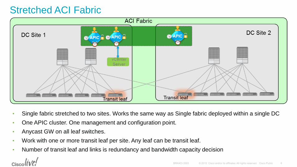
• Single fabric stretched to two sites. Works the same way as Single fabric deployed within a single DC
• One APIC cluster. One management and configuration point.
• Anycast GW on all leaf switches.
• Work with one or more transit leaf per site. Any leaf can be transit leaf.
• Number of transit leaf and links is redundancy and bandwidth capacity decision
Stretched ACI Fabric
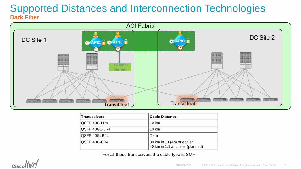
Supported Distances and Interconnection Technologies Dark Fiber
Transceivers Cable Distance
QSFP-40G-LR4 10 km
QSFP-40GE-LR4 10 km
QSFP-40GLR4L 2 km
QSFP-40G-ER4 30 km in 1.0(4h) or earlier
40 km in 1.1 and later (planned)
For all these transceivers the cable type is SMF
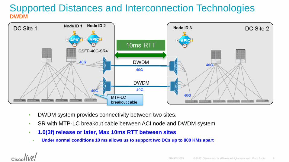
Supported Distances and Interconnection Technologies DWDM
• DWDM system provides connectivity between two sites.
• SR with MTP-LC breakout cable between ACI node and DWDM system
• 1.0(3f) release or later, Max 10ms RTT between sites
• Under normal conditions 10 ms allows us to support two DCs up to 800 KMs apart
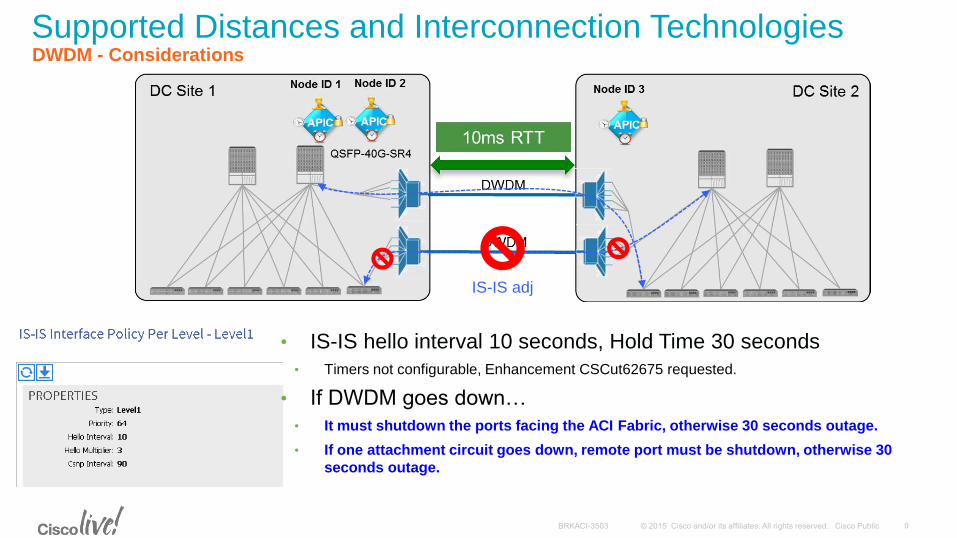
Supported Distances and Interconnection Technologies DWDM - Considerations
IS-IS adj
• IS-IS hello interval 10 seconds, Hold Time 30 seconds
• Timers not configurable, Enhancement CSCut62675 requested.
• If DWDM goes down…
• It must shutdown the ports facing the ACI Fabric, otherwise 30 seconds outage.
• If one attachment circuit goes down, remote port must be shutdown, otherwise 30
seconds outage.
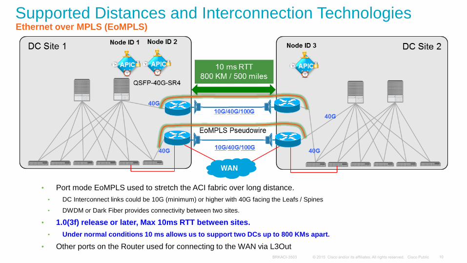
Supported Distances and Interconnection Technologies Ethernet over MPLS (EoMPLS)
• Port mode EoMPLS used to stretch the ACI fabric over long distance.
• DC Interconnect links could be 10G (minimum) or higher with 40G facing the Leafs / Spines
• DWDM or Dark Fiber provides connectivity between two sites.
• 1.0(3f) release or later, Max 10ms RTT between sites.
• Under normal conditions 10 ms allows us to support two DCs up to 800 KMs apart.
• Other ports on the Router used for connecting to the WAN via L3Out
Please provide your input to the questions asked on the mobile App.
What is the distance between
your Data Centers?
What kind of links do you have
between your Data Centers?
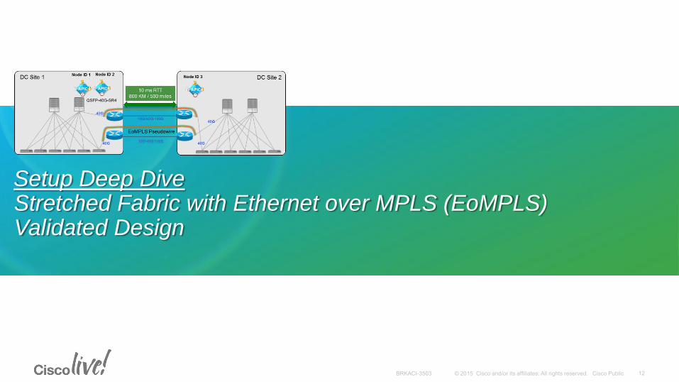
Setup Deep Dive Stretched Fabric with Ethernet over MPLS (EoMPLS) Validated Design
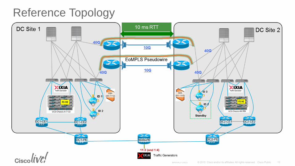
Reference Topology
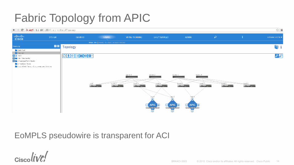
Fabric Topology from APIC
EoMPLS pseudowire is transparent for ACI
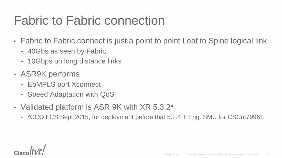
• Fabric to Fabric connect is just a point to point Leaf to Spine logical link
• 40Gbs as seen by Fabric
• 10Gbps on long distance links
• ASR9K performs
• EoMPLS port Xconnect
• Speed Adaptation with QoS
• Validated platform is ASR 9K with XR 5.3.2*
• *CCO FCS Sept 2015, for deployment before that 5.2.4 + Eng. SMU for CSCut79961
Fabric to Fabric connection
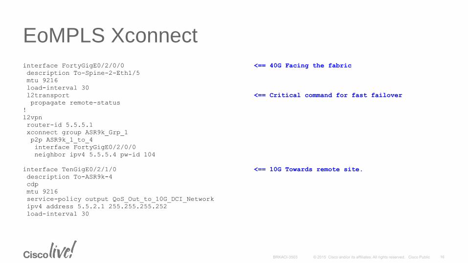
interface FortyGigE0/2/0/0 <== 40G Facing the fabric
description To-Spine-2-Eth1/5
mtu 9216
load-interval 30
l2transport <== Critical command for fast failover
propagate remote-status
!
l2vpn
router-id 5.5.5.1
xconnect group ASR9k_Grp_1
p2p ASR9k_1_to_4
interface FortyGigE0/2/0/0
neighbor ipv4 5.5.5.4 pw-id 104
interface TenGigE0/2/1/0 <== 10G Towards remote site.
description To-ASR9k-4
cdp
mtu 9216
service-policy output QoS_Out_to_10G_DCI_Network
ipv4 address 5.5.2.1 255.255.255.252
load-interval 30
EoMPLS Xconnect
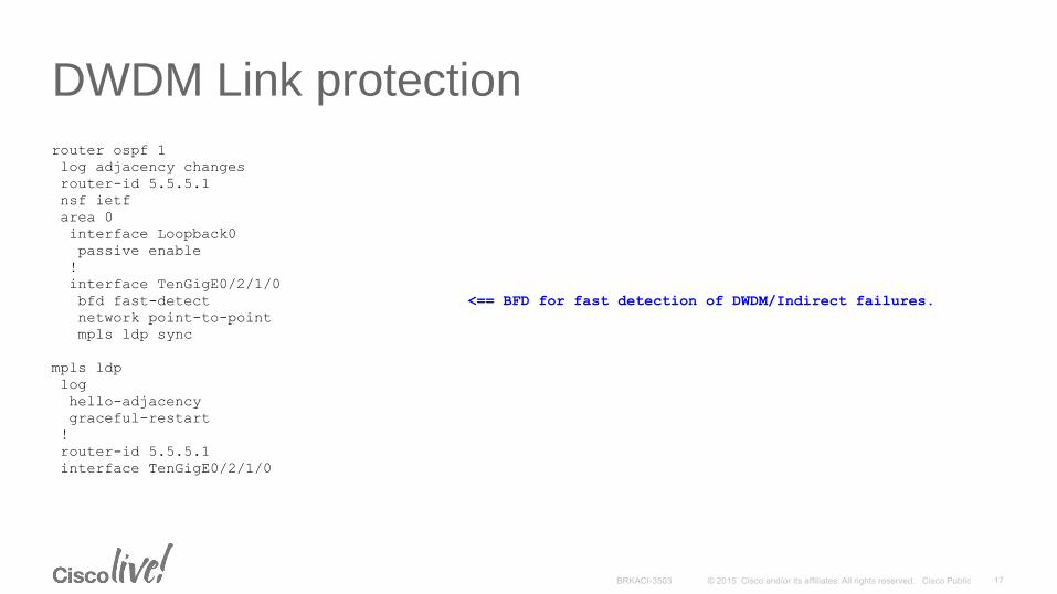
router ospf 1
log adjacency changes
router-id 5.5.5.1
nsf ietf
area 0
interface Loopback0
passive enable
!
interface TenGigE0/2/1/0
bfd fast-detect <== BFD for fast detection of DWDM/Indirect failures.
network point-to-point
mpls ldp sync
mpls ldp
log
hello-adjacency
graceful-restart
!
router-id 5.5.5.1
interface TenGigE0/2/1/0
DWDM Link protection
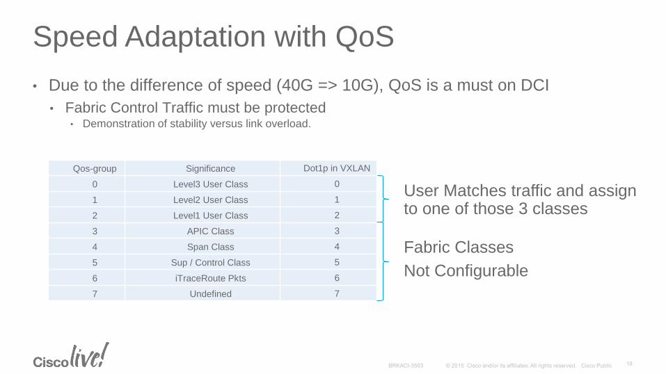
• Due to the difference of speed (40G => 10G), QoS is a must on DCI
• Fabric Control Traffic must be protected • Demonstration of stability versus link overload.
Speed Adaptation with QoS
Qos-group Significance Dot1p in VXLAN
0 Level3 User Class 0
1 Level2 User Class 1
2 Level1 User Class 2
3 APIC Class 3
4 Span Class 4
5 Sup / Control Class 5
6 iTraceRoute Pkts 6
7 Undefined 7
Fabric Classes
Not Configurable
User Matches traffic and assign to one of those 3 classes
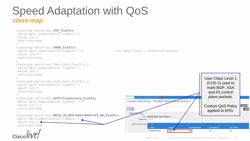
class-map match-any SUP_Traffic
match mpls experimental topmost 5
match cos 5
end-class-map
!
class-map match-any SPAN_Traffic
match mpls experimental topmost 7 4 <== Span Class + Undefined merged
match cos 4 7
end-class-map
!
class-map match-any User_Data_Traffic_1
match mpls experimental topmost 1
match cos 1
end-class-map
!
class-map match-any User_Data_Traffic_2
match mpls experimental topmost 0
match cos 0
end-class-map
!
class-map match-any APIC+Traceroute_Traffic
match mpls experimental topmost 3 6
match cos 3 6
end-class-map
!
class-map match-any MPLS_CE_BGP+ASA+vASA+vF5_HA_Traffic
match mpls experimental topmost 2
match cos 2
end-class-map
Speed Adaptation with QoS class-map
User Class Level 1
(COS 2) used to
mark BGP, ASA
and F5 control
plane packets.
Custom QoS Policy
applied to EPG.
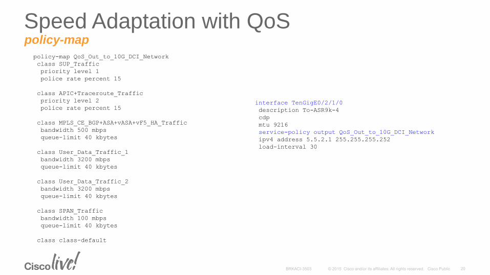
policy-map QoS_Out_to_10G_DCI_Network
class SUP_Traffic
priority level 1
police rate percent 15
class APIC+Traceroute_Traffic
priority level 2
police rate percent 15
class MPLS_CE_BGP+ASA+vASA+vF5_HA_Traffic
bandwidth 500 mbps
queue-limit 40 kbytes
class User_Data_Traffic_1
bandwidth 3200 mbps
queue-limit 40 kbytes
class User_Data_Traffic_2
bandwidth 3200 mbps
queue-limit 40 kbytes
class SPAN_Traffic
bandwidth 100 mbps
queue-limit 40 kbytes
class class-default
Speed Adaptation with QoS policy-map
interface TenGigE0/2/1/0
description To-ASR9k-4
cdp
mtu 9216
service-policy output QoS_Out_to_10G_DCI_Network
ipv4 address 5.5.2.1 255.255.255.252
load-interval 30
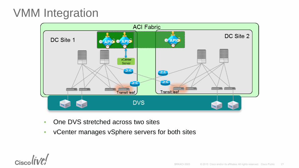
• One DVS stretched across two sites
• vCenter manages vSphere servers for both sites
VMM Integration
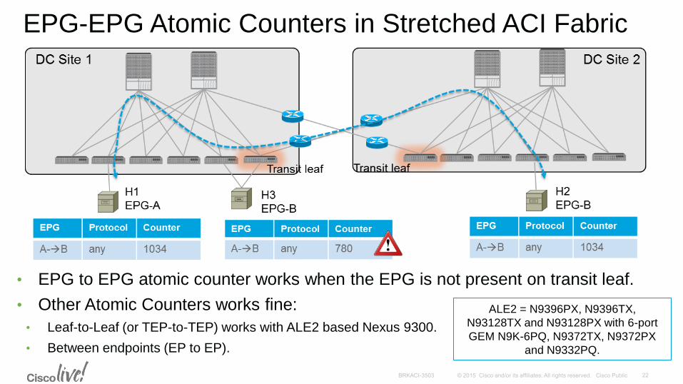
EPG-EPG Atomic Counters in Stretched ACI Fabric
• EPG to EPG atomic counter works when the EPG is not present on transit leaf.
• Other Atomic Counters works fine:
• Leaf-to-Leaf (or TEP-to-TEP) works with ALE2 based Nexus 9300.
• Between endpoints (EP to EP).
ALE2 = N9396PX, N9396TX,
N93128TX and N93128PX with 6-port
GEM N9K-6PQ, N9372TX, N9372PX
and N9332PQ.
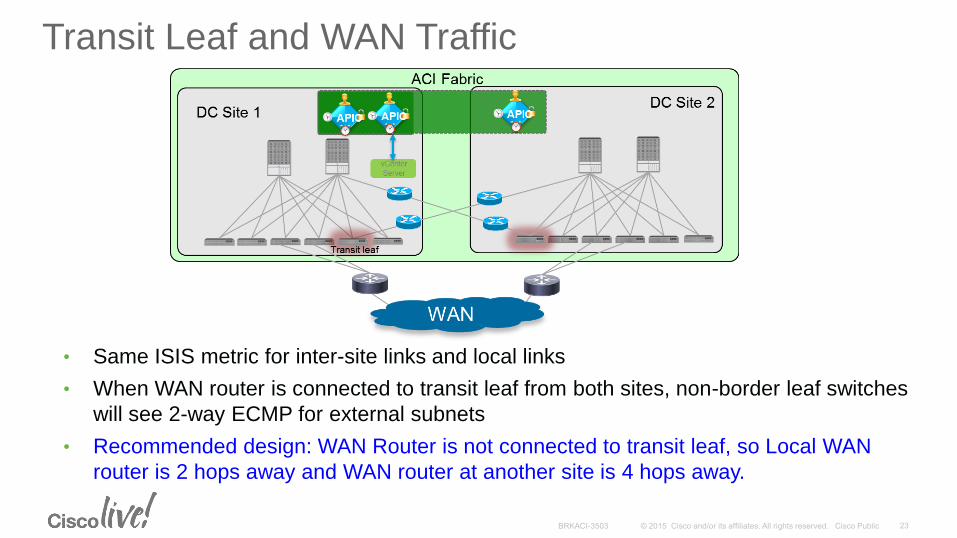
Transit Leaf and WAN Traffic
• Same ISIS metric for inter-site links and local links
• When WAN router is connected to transit leaf from both sites, non-border leaf switches
will see 2-way ECMP for external subnets
• Recommended design: WAN Router is not connected to transit leaf, so Local WAN
router is 2 hops away and WAN router at another site is 4 hops away.
WAN Edge
Router
CDP: Disabled
LLDP: Disabled
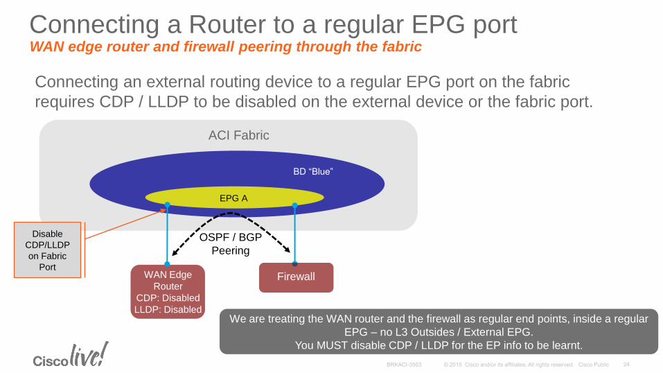
Connecting a Router to a regular EPG port WAN edge router and firewall peering through the fabric
Connecting an external routing device to a regular EPG port on the fabric
requires CDP / LLDP to be disabled on the external device or the fabric port.
ACI Fabric
BD “Blue”
EPG A
Firewall
OSPF / BGP
Peering
We are treating the WAN router and the firewall as regular end points, inside a regular
EPG – no L3 Outsides / External EPG.
You MUST disable CDP / LLDP for the EP info to be learnt.
Disable
CDP/LLDP
on Fabric
Port
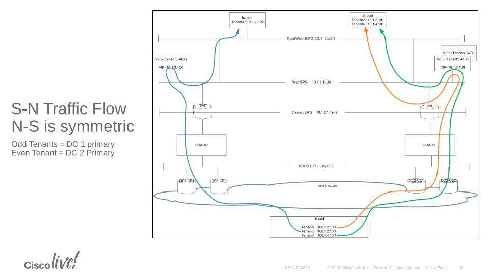
S-N Traffic Flow N-S is symmetric
Odd Tenants = DC 1 primary Even Tenant = DC 2 Primary
RealWeb EPG 10.1.4.1/24
WAN EPG Layer 2
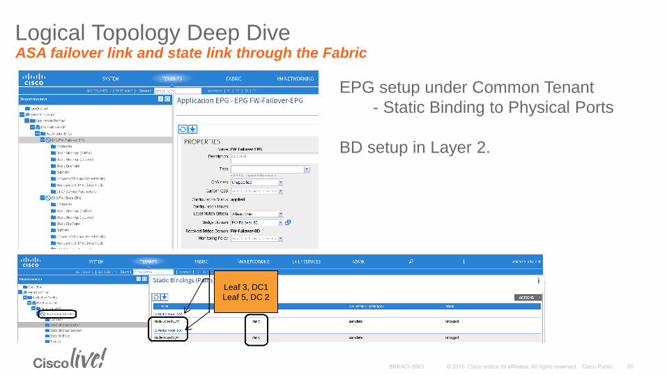
Logical Topology Deep Dive ASA failover link and state link through the Fabric
EPG setup under Common Tenant
- Static Binding to Physical Ports
BD setup in Layer 2.
Leaf 3, DC1
Leaf 5, DC 2
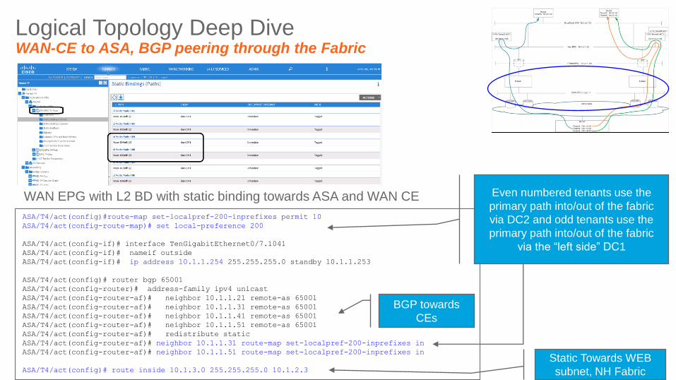
Logical Topology Deep Dive WAN-CE to ASA, BGP peering through the Fabric
WAN EPG with L2 BD with static binding towards ASA and WAN CE
ASA/T4/act(config)#route-map set-localpref-200-inprefixes permit 10
ASA/T4/act(config-route-map)# set local-preference 200
ASA/T4/act(config-if)# interface TenGigabitEthernet0/7.1041
ASA/T4/act(config-if)# nameif outside
ASA/T4/act(config-if)# ip address 10.1.1.254 255.255.255.0 standby 10.1.1.253
ASA/T4/act(config)# router bgp 65001
ASA/T4/act(config-router)# address-family ipv4 unicast
ASA/T4/act(config-router-af)# neighbor 10.1.1.21 remote-as 65001
ASA/T4/act(config-router-af)# neighbor 10.1.1.31 remote-as 65001
ASA/T4/act(config-router-af)# neighbor 10.1.1.41 remote-as 65001
ASA/T4/act(config-router-af)# neighbor 10.1.1.51 remote-as 65001
ASA/T4/act(config-router-af)# redistribute static
ASA/T4/act(config-router-af)# neighbor 10.1.1.31 route-map set-localpref-200-inprefixes in
ASA/T4/act(config-router-af)# neighbor 10.1.1.51 route-map set-localpref-200-inprefixes in
ASA/T4/act(config)# route inside 10.1.3.0 255.255.255.0 10.1.2.3
BGP towards
CEs
Static Towards WEB
subnet, NH Fabric
Even numbered tenants use the
primary path into/out of the fabric
via DC2 and odd tenants use the
primary path into/out of the fabric
via the “left side” DC1
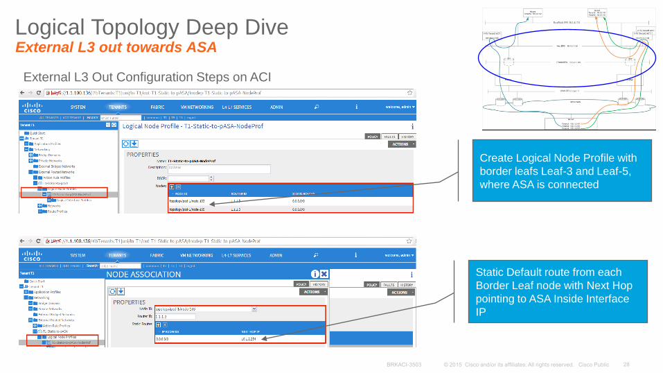
Logical Topology Deep Dive External L3 out towards ASA
External L3 Out Configuration Steps on ACI
Create Logical Node Profile with
border leafs Leaf-3 and Leaf-5,
where ASA is connected
Static Default route from each
Border Leaf node with Next Hop
pointing to ASA Inside Interface
IP
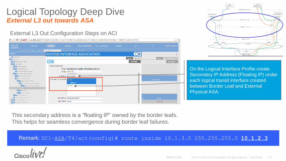
Logical Topology Deep Dive External L3 out towards ASA
External L3 Out Configuration Steps on ACI
On the Logical Interface Profile create
Secondary IP Address (Floating IP) under
each logical transit interface created
between Border Leaf and External
Physical ASA.
This secondary address is a “floating IP” owned by the border leafs.
This helps for seamless convergence during border leaf failures.
Remark: DC1-ASA/T4/act(config)# route inside 10.1.3.0 255.255.255.0 10.1.2.3
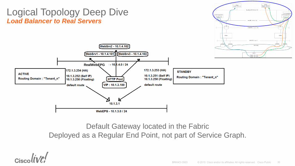
Logical Topology Deep Dive Load Balancer to Real Servers
Default Gateway located in the Fabric
Deployed as a Regular End Point, not part of Service Graph.
RealWebEPG
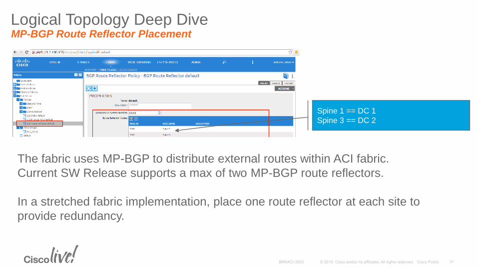
Logical Topology Deep Dive MP-BGP Route Reflector Placement
Spine 1 == DC 1
Spine 3 == DC 2
The fabric uses MP-BGP to distribute external routes within ACI fabric.
Current SW Release supports a max of two MP-BGP route reflectors.
In a stretched fabric implementation, place one route reflector at each site to
provide redundancy.
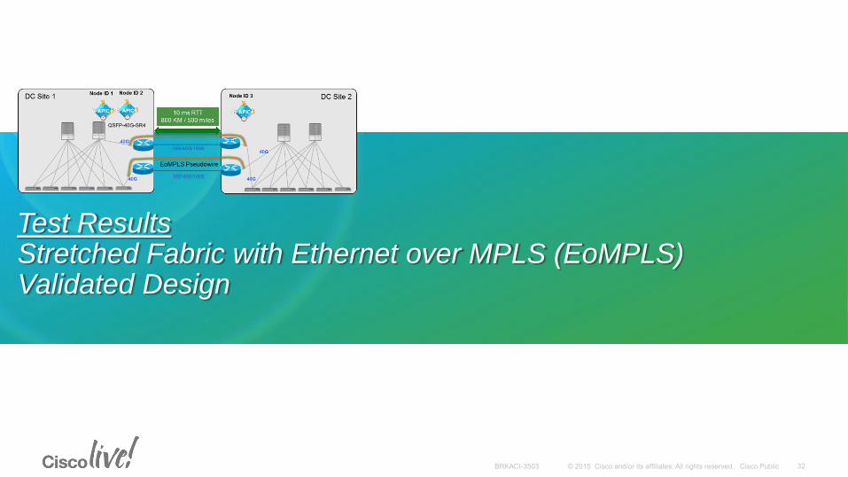
Test Results Stretched Fabric with Ethernet over MPLS (EoMPLS) Validated Design
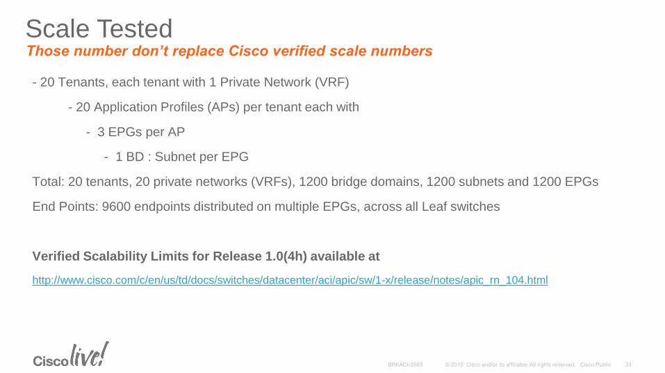
- 20 Tenants, each tenant with 1 Private Network (VRF)
- 20 Application Profiles (APs) per tenant each with
- 3 EPGs per AP
- 1 BD : Subnet per EPG
Total: 20 tenants, 20 private networks (VRFs), 1200 bridge domains, 1200 subnets and 1200 EPGs
End Points: 9600 endpoints distributed on multiple EPGs, across all Leaf switches
Verified Scalability Limits for Release 1.0(4h) available at
http://www.cisco.com/c/en/us/td/docs/switches/datacenter/aci/apic/sw/1-x/release/notes/apic_rn_104.html
Scale Tested Those number don’t replace Cisco verified scale numbers
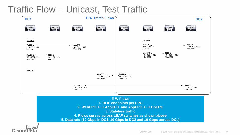
Traffic Flow – Unicast, Test Traffic
W Flows-E
1. 10 IP endpoints per EPG
2. WebEPG AppEPG and AppEPG DbEPG
3. Stateless traffic
4. Flows spread across LEAF switches as shown above
5. Data rate (10 Gbps in DC1, 10 Gbps in DC2 and 10 Gbps across DCs)
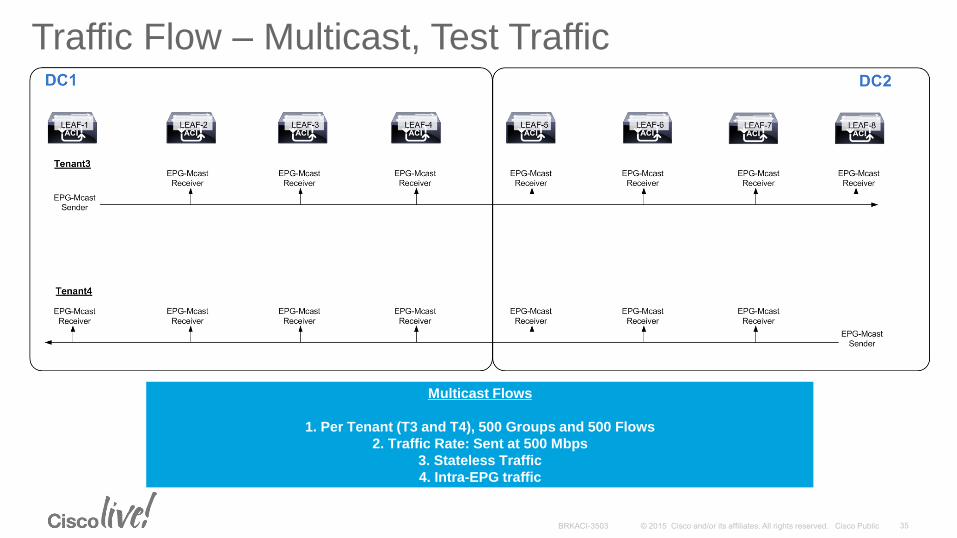
Traffic Flow – Multicast, Test Traffic
FlowsMulticast
1. Per Tenant (T3 and T4), 500 Groups and 500 Flows
2. Traffic Rate: Sent at 500 Mbps
3. Stateless Traffic
4. Intra-EPG traffic
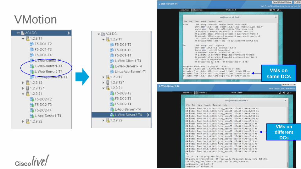
VMotion
VMs on
same DCs
VMs on
different
DCs
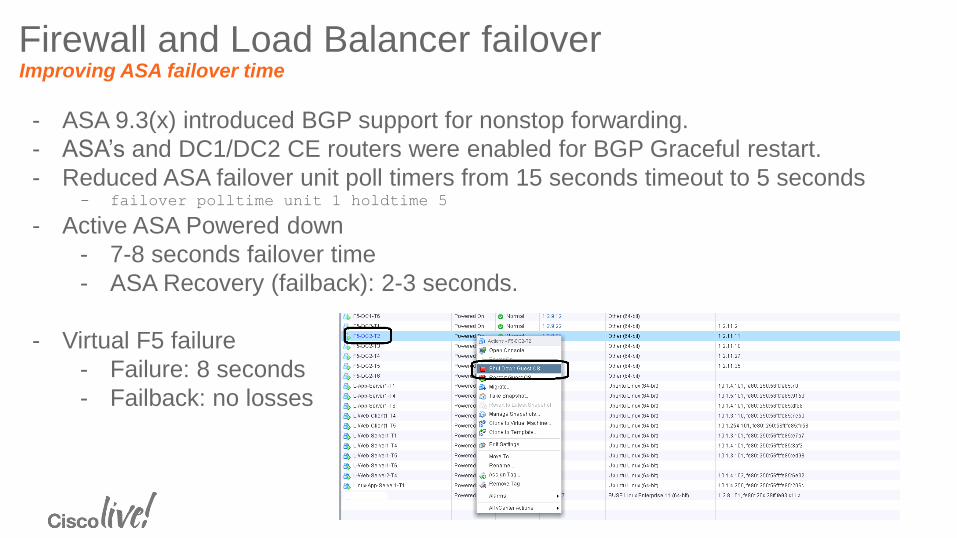
Firewall and Load Balancer failover Improving ASA failover time
- ASA 9.3(x) introduced BGP support for nonstop forwarding.
- ASA’s and DC1/DC2 CE routers were enabled for BGP Graceful restart.
- Reduced ASA failover unit poll timers from 15 seconds timeout to 5 seconds - failover polltime unit 1 holdtime 5
- Active ASA Powered down
- 7-8 seconds failover time
- ASA Recovery (failback): 2-3 seconds.
- Virtual F5 failure
- Failure: 8 seconds
- Failback: no losses
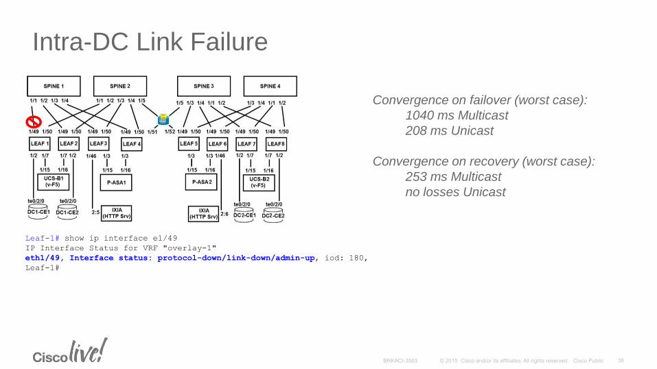
Intra-DC Link Failure
Leaf-1# show ip interface e1/49
IP Interface Status for VRF "overlay-1"
eth1/49, Interface status: protocol-down/link-down/admin-up, iod: 180,
Leaf-1#
Convergence on failover (worst case):
1040 ms Multicast
208 ms Unicast
Convergence on recovery (worst case):
253 ms Multicast
no losses Unicast
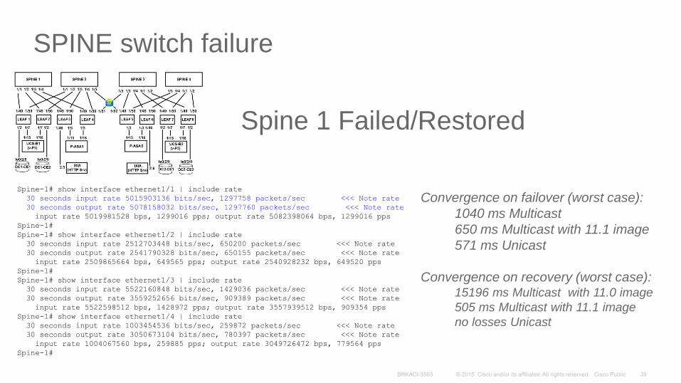
SPINE switch failure
Spine-1# show interface ethernet1/1 | include rate
30 seconds input rate 5015903136 bits/sec, 1297758 packets/sec <<< Note rate
30 seconds output rate 5078158032 bits/sec, 1297760 packets/sec <<< Note rate
input rate 5019981528 bps, 1299016 pps; output rate 5082398064 bps, 1299016 pps
Spine-1#
Spine-1# show interface ethernet1/2 | include rate
30 seconds input rate 2512703448 bits/sec, 650200 packets/sec <<< Note rate
30 seconds output rate 2541790328 bits/sec, 650155 packets/sec <<< Note rate
input rate 2509865664 bps, 649565 pps; output rate 2540928232 bps, 649520 pps
Spine-1#
Spine-1# show interface ethernet1/3 | include rate
30 seconds input rate 5522160848 bits/sec, 1429036 packets/sec <<< Note rate
30 seconds output rate 3559252656 bits/sec, 909389 packets/sec <<< Note rate
input rate 5522598512 bps, 1428972 pps; output rate 3557939512 bps, 909354 pps
Spine-1# show interface ethernet1/4 | include rate
30 seconds input rate 1003454536 bits/sec, 259872 packets/sec <<< Note rate
30 seconds output rate 3050673104 bits/sec, 780397 packets/sec <<< Note rate
input rate 1004067560 bps, 259885 pps; output rate 3049726472 bps, 779564 pps
Spine-1#
Spine 1 Failed/Restored
Convergence on failover (worst case):
1040 ms Multicast
650 ms Multicast with 11.1 image
571 ms Unicast
Convergence on recovery (worst case): 15196 ms Multicast with 11.0 image
505 ms Multicast with 11.1 image
no losses Unicast
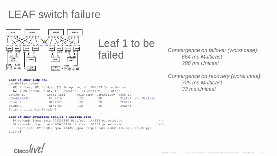
LEAF switch failure
Leaf-1# show lldp nei
Capability codes:
(R) Router, (B) Bridge, (T) Telephone, (C) DOCSIS Cable Device
(W) WLAN Access Point, (P) Repeater, (S) Station, (O) Other
Device ID Local Intf Hold-time Capability Port ID
N3K-A1-8-32 Eth1/16 120 BR Eth1/1 <<< Eth1/16
Spine-1 Eth1/49 120 BR Eth1/1
Spine-2 Eth1/50 120 BR Eth1/1
Total entries displayed: 3
Leaf-1# show interface eth1/16 | include rate
30 seconds input rate 505351360 bits/sec, 144322 packets/sec <<<
30 seconds output rate 200479760 bits/sec, 57737 packets/sec <<<
input rate 399586040 bps, 114265 pps; output rate 158359176 bps, 45710 pps
Leaf-1#
Leaf 1 to be failed
Convergence on failover (worst case):
664 ms Multicast
286 ms Unicast
Convergence on recovery (worst case):
725 ms Multicast
33 ms Unicast
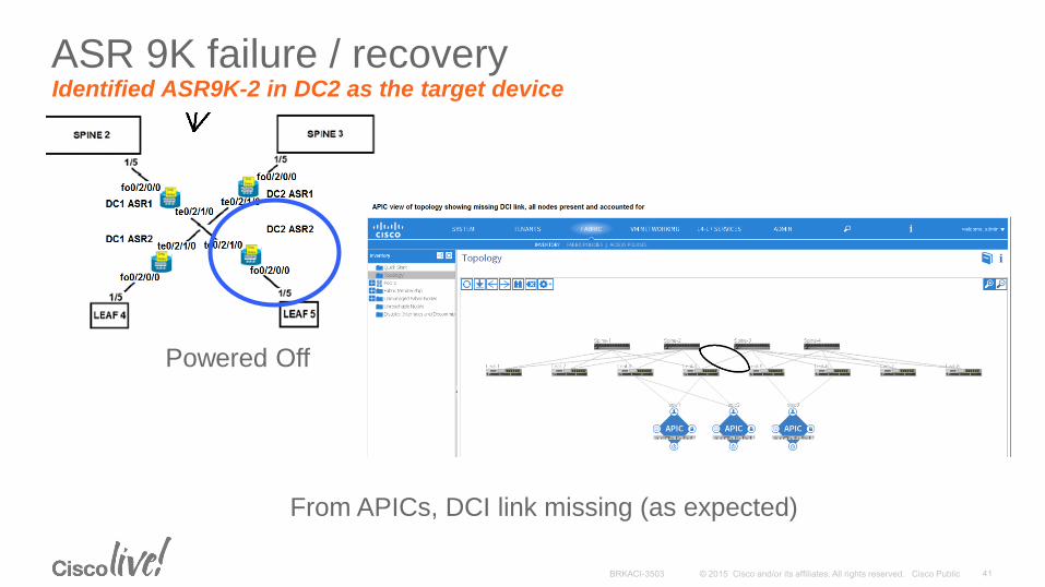
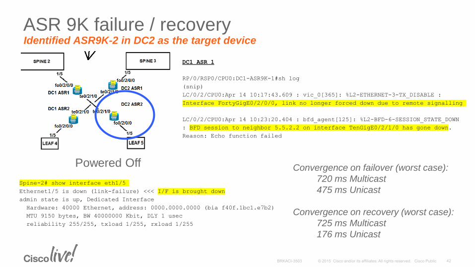
ASR 9K failure / recovery Identified ASR9K-2 in DC2 as the target device
Powered Off
From APICs, DCI link missing (as expected)
ASR 9K failure / recovery Identified ASR9K-2 in DC2 as the target device
Powered Off
DC1 ASR 1
RP/0/RSP0/CPU0:DC1-ASR9K-1#sh log
(snip)
LC/0/2/CPU0:Apr 14 10:17:43.609 : vic_0[365]: %L2-ETHERNET-3-TX_DISABLE :
Interface FortyGigE0/2/0/0, link no longer forced down due to remote signalling
LC/0/2/CPU0:Apr 14 10:23:20.404 : bfd_agent[125]: %L2-BFD-6-SESSION_STATE_DOWN
: BFD session to neighbor 5.5.2.2 on interface TenGigE0/2/1/0 has gone down.
Reason: Echo function failed
Spine-2# show interface eth1/5
Ethernet1/5 is down (link-failure) <<< I/F is brought down
admin state is up, Dedicated Interface
Hardware: 40000 Ethernet, address: 0000.0000.0000 (bia f40f.1bc1.e7b2)
MTU 9150 bytes, BW 40000000 Kbit, DLY 1 usec
reliability 255/255, txload 1/255, rxload 1/255
Convergence on failover (worst case):
720 ms Multicast
475 ms Unicast
Convergence on recovery (worst case):
725 ms Multicast
176 ms Unicast
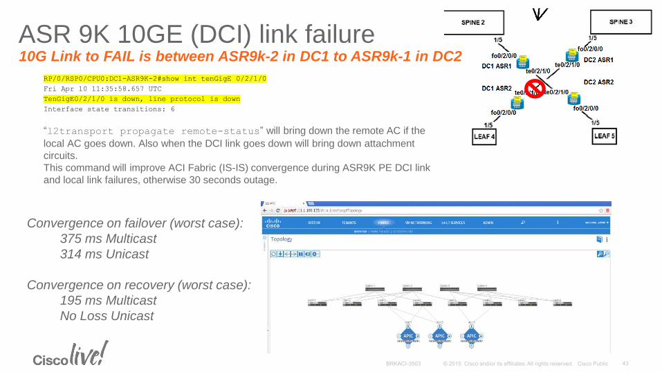
RP/0/RSP0/CPU0:DC1-ASR9K-2#show int tenGigE 0/2/1/0
Fri Apr 10 11:35:58.657 UTC
TenGigE0/2/1/0 is down, line protocol is down
Interface state transitions: 6
ASR 9K 10GE (DCI) link failure 10G Link to FAIL is between ASR9k-2 in DC1 to ASR9k-1 in DC2
“l2transport propagate remote-status” will bring down the remote AC if the
local AC goes down. Also when the DCI link goes down will bring down attachment
circuits.
This command will improve ACI Fabric (IS-IS) convergence during ASR9K PE DCI link
and local link failures, otherwise 30 seconds outage.
Convergence on failover (worst case):
375 ms Multicast
314 ms Unicast
Convergence on recovery (worst case):
195 ms Multicast
No Loss Unicast
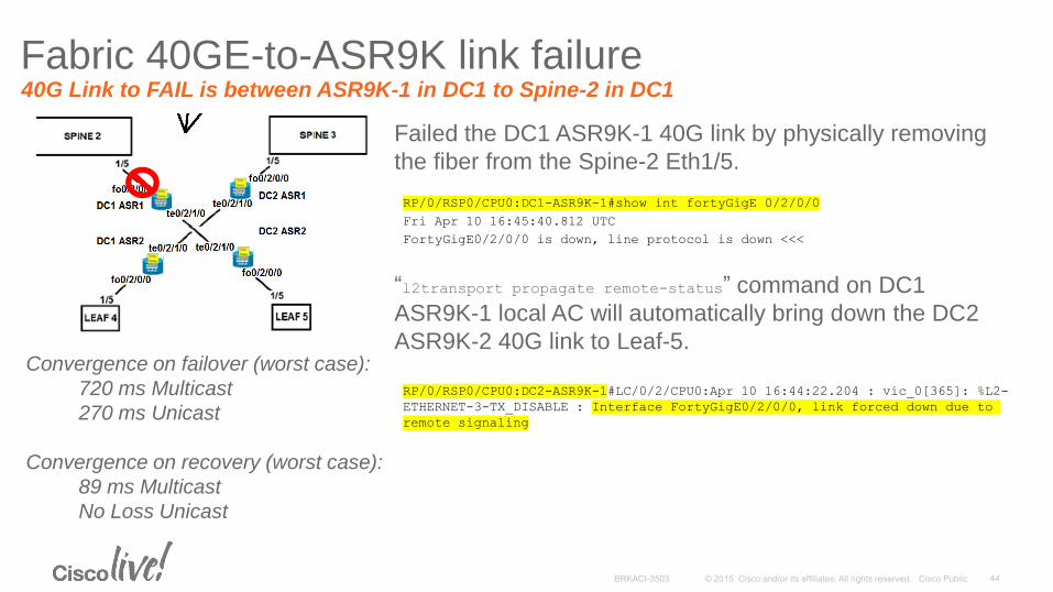
Convergence on failover (worst case):
720 ms Multicast
270 ms Unicast
Convergence on recovery (worst case):
89 ms Multicast
No Loss Unicast
Fabric 40GE-to-ASR9K link failure 40G Link to FAIL is between ASR9K-1 in DC1 to Spine-2 in DC1
Failed the DC1 ASR9K-1 40G link by physically removing
the fiber from the Spine-2 Eth1/5.
RP/0/RSP0/CPU0:DC1-ASR9K-1#show int fortyGigE 0/2/0/0
Fri Apr 10 16:45:40.812 UTC
FortyGigE0/2/0/0 is down, line protocol is down <<<
“l2transport propagate remote-status” command on DC1
ASR9K-1 local AC will automatically bring down the DC2
ASR9K-2 40G link to Leaf-5.
RP/0/RSP0/CPU0:DC2-ASR9K-1#LC/0/2/CPU0:Apr 10 16:44:22.204 : vic_0[365]: %L2-
ETHERNET-3-TX_DISABLE : Interface FortyGigE0/2/0/0, link forced down due to
remote signaling
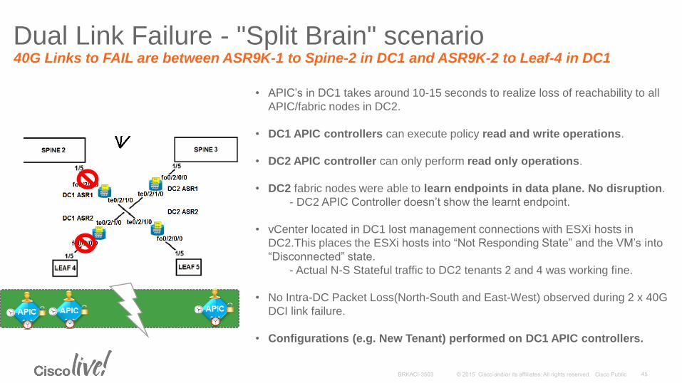
Dual Link Failure - "Split Brain" scenario 40G Links to FAIL are between ASR9K-1 to Spine-2 in DC1 and ASR9K-2 to Leaf-4 in DC1
• APIC’s in DC1 takes around 10-15 seconds to realize loss of reachability to all
APIC/fabric nodes in DC2.
• DC1 APIC controllers can execute policy read and write operations.
• DC2 APIC controller can only perform read only operations.
• DC2 fabric nodes were able to learn endpoints in data plane. No disruption.
- DC2 APIC Controller doesn’t show the learnt endpoint.
• vCenter located in DC1 lost management connections with ESXi hosts in
DC2.This places the ESXi hosts into “Not Responding State” and the VM’s into
“Disconnected” state.
- Actual N-S Stateful traffic to DC2 tenants 2 and 4 was working fine.
• No Intra-DC Packet Loss(North-South and East-West) observed during 2 x 40G
DCI link failure.
• Configurations (e.g. New Tenant) performed on DC1 APIC controllers.
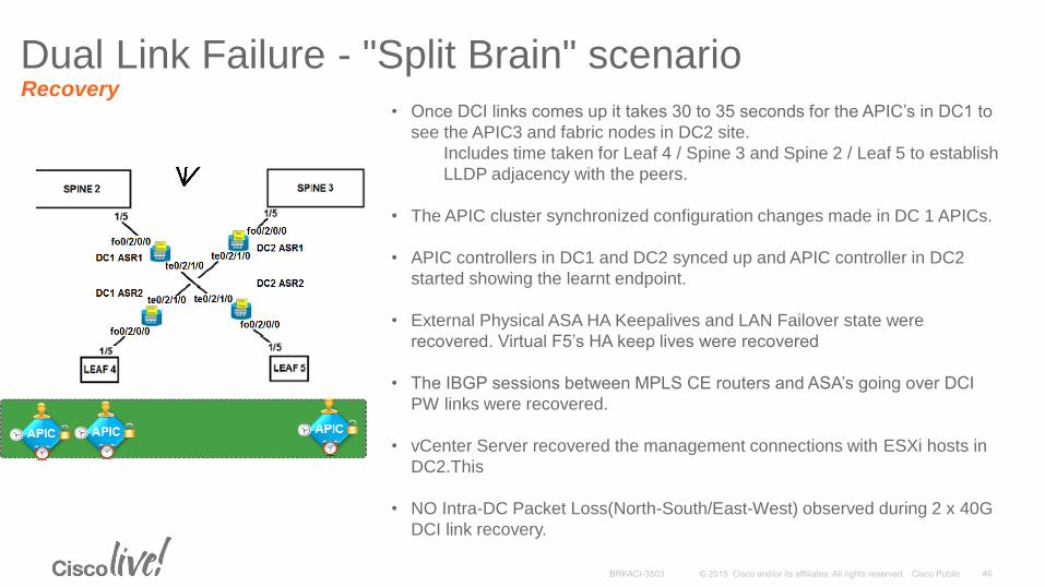
Dual Link Failure - "Split Brain" scenario Recovery
• Once DCI links comes up it takes 30 to 35 seconds for the APIC’s in DC1 to
see the APIC3 and fabric nodes in DC2 site.
Includes time taken for Leaf 4 / Spine 3 and Spine 2 / Leaf 5 to establish
LLDP adjacency with the peers.
• The APIC cluster synchronized configuration changes made in DC 1 APICs.
• APIC controllers in DC1 and DC2 synced up and APIC controller in DC2
started showing the learnt endpoint.
• External Physical ASA HA Keepalives and LAN Failover state were
recovered. Virtual F5’s HA keep lives were recovered
• The IBGP sessions between MPLS CE routers and ASA’s going over DCI
PW links were recovered.
• vCenter Server recovered the management connections with ESXi hosts in
DC2.This
• NO Intra-DC Packet Loss(North-South/East-West) observed during 2 x 40G
DCI link recovery.
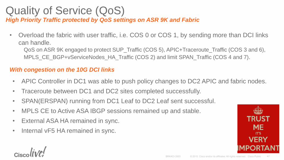
Quality of Service (QoS) High Priority Traffic protected by QoS settings on ASR 9K and Fabric
• Overload the fabric with user traffic, i.e. COS 0 or COS 1, by sending more than DCI links
can handle. QoS on ASR 9K engaged to protect SUP_Traffic (COS 5), APIC+Traceroute_Traffic (COS 3 and 6),
MPLS_CE_BGP+vServiceNodes_HA_Traffic (COS 2) and limit SPAN_Traffic (COS 4 and 7).
With congestion on the 10G DCI links
• APIC Controller in DC1 was able to push policy changes to DC2 APIC and fabric nodes.
• Traceroute between DC1 and DC2 sites completed successfully.
• SPAN(ERSPAN) running from DC1 Leaf to DC2 Leaf sent successful.
• MPLS CE to Active ASA IBGP sessions remained up and stable.
• External ASA HA remained in sync.
• Internal vF5 HA remained in sync.
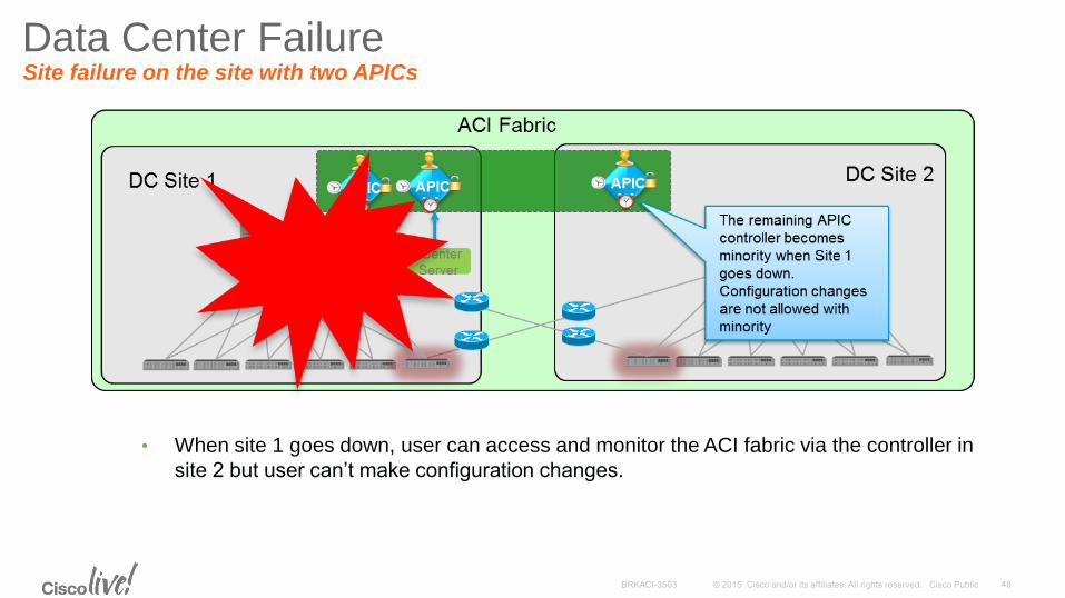
• When site 1 goes down, user can access and monitor the ACI fabric via the controller in
site 2 but user can’t make configuration changes.
Data Center Failure Site failure on the site with two APICs
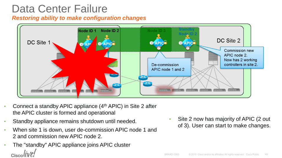
• Connect a standby APIC appliance (4th APIC) in Site 2 after
the APIC cluster is formed and operational
• Standby appliance remains shutdown until needed.
• When site 1 is down, user de-commission APIC node 1 and
2 and commission new APIC node 2.
• The "standby" APIC appliance joins APIC cluster
AN
IMA
TE
D S
lide
• Site 2 now has majority of APIC (2 out
of 3). User can start to make changes.
Data Center Failure Restoring ability to make configuration changes
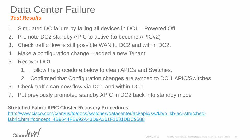
1. Simulated DC failure by failing all devices in DC1 – Powered Off
2. Promote DC2 standby APIC to active (to become APIC#2)
3. Check traffic flow is still possible WAN to DC2 and within DC2.
4. Make a configuration change – added a new Tenant.
5. Recover DC1.
1. Follow the procedure below to clean APICs and Switches.
2. Confirmed that Configuration changes are synced to DC 1 APIC/Switches
6. Check traffic can now flow via DC1 and within DC 1
7. Put previously promoted standby APIC in DC2 back into standby mode
Stretched Fabric APIC Cluster Recovery Procedures
http://www.cisco.com/c/en/us/td/docs/switches/datacenter/aci/apic/sw/kb/b_kb-aci-stretched-
fabric.html#concept_4B9644FE992A43D9A261F1531DBC9588
Data Center Failure Test Results
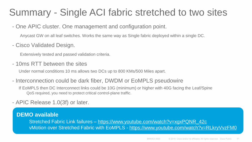
- One APIC cluster. One management and configuration point.
Anycast GW on all leaf switches. Works the same way as Single fabric deployed within a single DC.
- Cisco Validated Design.
Extensively tested and passed validation criteria.
- 10ms RTT between the sites
Under normal conditions 10 ms allows two DCs up to 800 KMs/500 Miles apart.
- Interconnection could be dark fiber, DWDM or EoMPLS pseudowire
If EoMPLS then DC Interconnect links could be 10G (minimum) or higher with 40G facing the Leaf/Spine QoS required, you need to protect critical control-plane traffic.
- APIC Release 1.0(3f) or later.
Summary - Single ACI fabric stretched to two sites
DEMO available
Stretched Fabric Link failures – https://www.youtube.com/watch?v=xgxPQNR_42c
vMotion over Stretched Fabric with EoMPLS - https://www.youtube.com/watch?v=RLkryVvzFM0
ACI Multi-Site Multiple APIC Clusters / Multiple Domains
The solutions presented from this slide onwards are still under testing / validations.
Target: Q4CY2015.
Please contact the presenters if you need to perform a Proof of Concept earlier.
Disclaimer
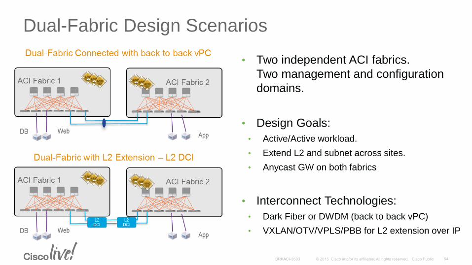
Dual-Fabric Design Scenarios
• Two independent ACI fabrics.
Two management and configuration
domains.
• Design Goals:
• Active/Active workload.
• Extend L2 and subnet across sites.
• Anycast GW on both fabrics
• Interconnect Technologies:
• Dark Fiber or DWDM (back to back vPC)
• VXLAN/OTV/VPLS/PBB for L2 extension over IP
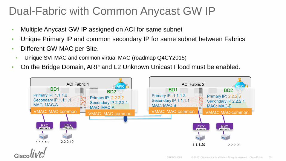
Dual-Fabric with Common Anycast GW IP
• Multiple Anycast GW IP assigned on ACI for same subnet
• Unique Primary IP and common secondary IP for same subnet between Fabrics
• Different GW MAC per Site.
• Unique SVI MAC and common virtual MAC (roadmap Q4CY2015)
• On the Bridge Domain, ARP and L2 Unknown Unicast Flood must be enabled.
VMAC: MAC-common VMAC: MAC-common VMAC: MAC-common VMAC: MAC-common
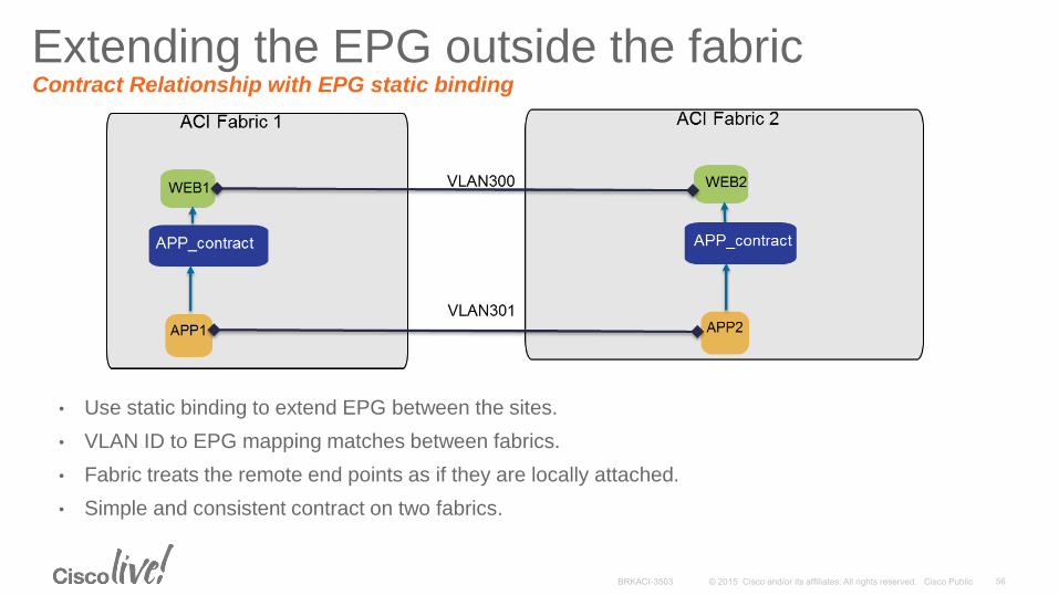
• Use static binding to extend EPG between the sites.
• VLAN ID to EPG mapping matches between fabrics.
• Fabric treats the remote end points as if they are locally attached.
• Simple and consistent contract on two fabrics.
Extending the EPG outside the fabric Contract Relationship with EPG static binding
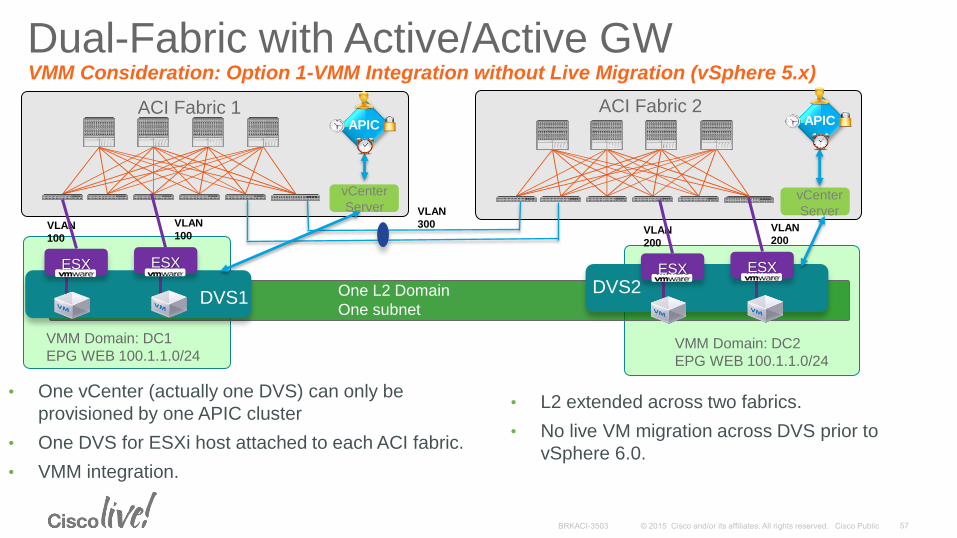
Dual-Fabric with Active/Active GW VMM Consideration: Option 1-VMM Integration without Live Migration (vSphere 5.x)
vCenter
Server
VLAN
100
VLAN
100
VMM Domain: DC1
EPG WEB 100.1.1.0/24
vCenter
Server
VLAN
200
VLAN
200
VMM Domain: DC2
EPG WEB 100.1.1.0/24
One L2 Domain
One subnet
VLAN
300
ACI Fabric 1 ACI Fabric 2 APIC APIC
ESX ESX
DVS1 DVS2
ESX ESX
• One vCenter (actually one DVS) can only be
provisioned by one APIC cluster
• One DVS for ESXi host attached to each ACI fabric.
• VMM integration.
• L2 extended across two fabrics.
• No live VM migration across DVS prior to
vSphere 6.0.
One L2 Domain
One subnet
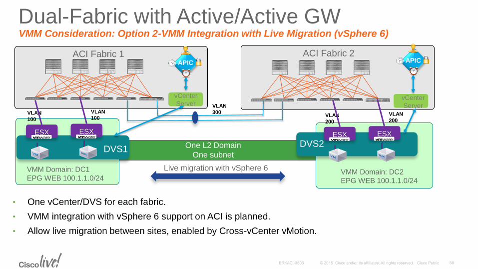
Dual-Fabric with Active/Active GW VMM Consideration: Option 2-VMM Integration with Live Migration (vSphere 6)
vCenter
Server
VLAN
100
VLAN
100
VMM Domain: DC1
EPG WEB 100.1.1.0/24
vCenter
Server
VLAN
200
VLAN
200
VMM Domain: DC2
EPG WEB 100.1.1.0/24
VLAN
300
ACI Fabric 1 ACI Fabric 2
• One vCenter/DVS for each fabric.
• VMM integration with vSphere 6 support on ACI is planned.
• Allow live migration between sites, enabled by Cross-vCenter vMotion.
APIC APIC
ESX ESX
DVS1 DVS2
ESX ESX
Live migration with vSphere 6
Please provide your input to the questions asked on the mobile App.
What Virtualization
Platform you expect to
be using in the next 12
months?
Which of the Dual-Site
deployment models you
plan to adopt in the next
12 months?
If you requirement is for
Dual-Fabric with L2 DCI
extension, how many
EPGs/VLANs do you need
to extend between the sites.
EPG static
binding
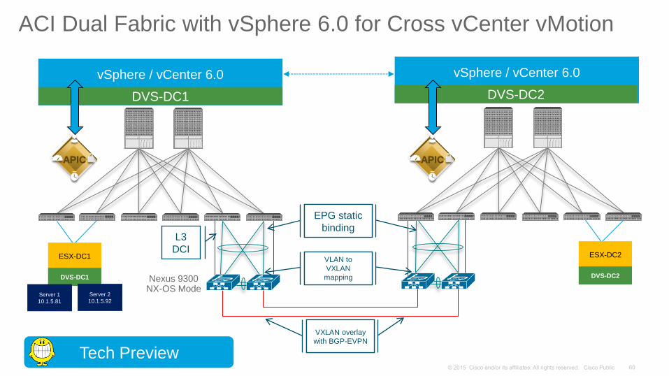
ACI Dual Fabric with vSphere 6.0 for Cross vCenter vMotion
vSphere / vCenter 6.0
DVS-DC1
vSphere / vCenter 6.0
DVS-DC2
APIC APIC
ESX-DC1
Nexus 9300 NX-OS Mode
EPG static
binding
EPG static
binding
VLAN to
VXLAN
mapping
EPG static
binding VXLAN overlay
with BGP-EVPN
DVS-DC1
Server 1
10.1.5.81
ESX-DC2
DVS-DC2
Server 2
10.1.5.92
Tech Preview
L3
DCI
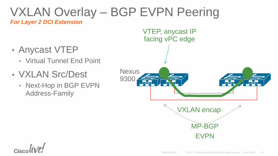
• Anycast VTEP • Virtual Tunnel End Point
• VXLAN Src/Dest • Next-Hop in BGP EVPN
Address-Family
MP-BGP
EVPN
VTEP, anycast IP facing vPC edge
VXLAN encap
VXLAN Overlay – BGP EVPN Peering For Layer 2 DCI Extension
Nexus 9300
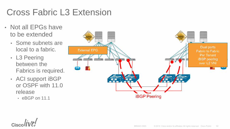
• Not all EPGs have to be extended
• Some subnets are local to a fabric.
• L3 Peering between the Fabrics is required.
• ACI support iBGP or OSPF with 11.0 release • eBGP on 11.1
Cross Fabric L3 Extension
ACI Fabric 1 ACI Fabric 2
vCenter
6.0 vCenter
6.0
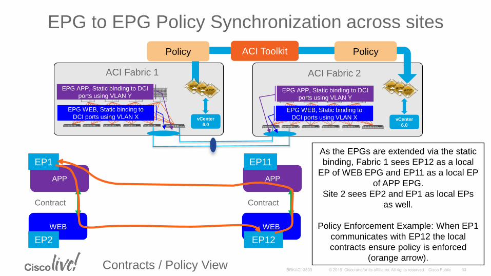
EPG WEB, Static binding to
DCI ports using VLAN X EPG WEB, Static binding to
DCI ports using VLAN X
Contracts / Policy View
EPG to EPG Policy Synchronization across sites
EPG APP, Static binding to DCI
ports using VLAN Y EPG APP, Static binding to DCI
ports using VLAN Y
APP
WEB
Contract
EP1
EP2
APP
WEB
Contract
EP11
EP12
As the EPGs are extended via the static
binding, Fabric 1 sees EP12 as a local
EP of WEB EPG and EP11 as a local EP
of APP EPG.
Site 2 sees EP2 and EP1 as local EPs
as well.
Policy Enforcement Example: When EP1
communicates with EP12 the local
contracts ensure policy is enforced
(orange arrow).
Policy ACI Toolkit Policy
Participate in the “My Favorite Speaker” Contest
• Promote your favorite speaker through Twitter and you could win $200 of Cisco Press products (@CiscoPress)
• Send a tweet and include
• Your favorite speaker’s Twitter handle @thiagovazquez @pbellaga
• Two hashtags: #CLUS #MyFavoriteSpeaker
• You can submit an entry for more than one of your “favorite” speakers
• Don’t forget to follow @CiscoLive and @CiscoPress
• View the official rules at http://bit.ly/CLUSwin
Promote Your Favorite Speaker and You Could Be a Winner
Complete Your Online Session Evaluation
Don’t forget: Cisco Live sessions will be available for viewing on-demand after the event at CiscoLive.com/Online
• Give us your feedback to be entered into a Daily Survey Drawing. A daily winner will receive a $750 Amazon gift card.
• Complete your session surveys though the Cisco Live mobile app or your computer on Cisco Live Connect.
Continue Your Education
• Demos in the Cisco campus
• Walk-in Self-Paced Labs
• Table Topics
• Meet the Engineer 1:1 meetings
• Related sessions
Thank you