Embed Size (px)
Citation preview
Particle Accelerator Engineering, London, October 2014
Phase Synchronisation Systems
Dr A.C. Dexter
Overview
Accelerator Synchronisation Examples
Categories of Timing Problems
Oscillators
Clock to Accelerator Cavity
Phase Locked Magnetrons
RF Interferometers
CLIC Crab Cavity Synchronisation
Laser Timing Distribution
Laser to RF

Particle Accelerator Engineering, London, October 2014
Accelerator Examples
Crab Cavity System IP
quadrupolequadrupole
Crab cavity Crab cavity
25 m
PositronsElectrons
Free Electron Laser
Bunch to RFOff crest acceleration
Voltage gain as function of relative position
Bunch position when RF field is maximum
Particle Accelerator Engineering, London, October 2014
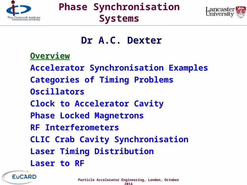
Categories of Timing Problems
• Stability Oscillators shift period with temperature, vibration etc. Voltage Controlled Oscillator (VCO) shifts period with applied voltage Atomic clock f/f ~ 10-14 ~ 60 fs per minute
• Synchronisation Two clocks with different periods at same place (Phase Locked Loop) Identical delivery time/phase at two places (Crab Cavity Problem) Same clock at two places
Resynchronisation requires constant propagation time of signal Detector with high resolution and low noise
• Trigger an event at a later and a different location Needs two stable clocks which are synchronised (FEL problem) Must be able to generate event from clock pulse with tiny jitter Work at DESY and MIT suggest 10fs achievable

Particle Accelerator Engineering, London 2014
Oscillators
RF Output
DC Input(changes frequency)
Input and reflection on output port
RF Output
DC Input(Changes phase)
reflection on output port
Filter
Low Pass Filter / integrator
VCO or Magnetron Oscillator
Phase Detector
Microwave Voltage Controller Oscillator
Crystal Oscillator
Frequency divider /R
Frequency divider /N
Oscillator using amplifier
Phase Locked Loop (Synchronises oscillators at different frequencies, jitter follows performance of microwave oscillator and long term stability follows crystal oscillator)
sensitive to temperature
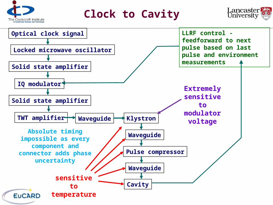
Clock to Cavity
Optical clock signal
Locked microwave oscillator
Solid state amplifier
IQ modulator
Solid state amplifier
TWT amplifier Klystron
Pulse compressor
Waveguide
Waveguide
Waveguide
Cavitysensitive to temperature
Extremely sensitive to modulator
voltage
LLRF control - feedforward to next pulse based on last pulse and environment measurements
Absolute timing impossible as every component and
connector adds phase uncertainty

Magnetron Exciting Superconducting Cavity
Demonstration of CW 2.45 GHz magnetron driving a specially manufactured superconducting cavity in a vertical test facility at JLab and the control of phase in the presence of microphonics was successful.
First demonstration and performance of an injection locked continuous wave magnetron to phase control a superconducting cavity A.C. Dexter, G. Burt, R. Carter, I. Tahir, H. Wang, K. Davis, and R. Rimmer, Physical Review Special Topics: Accelerators and Beams, Vol. 14, No. 3, 17.03.2011, p. 032001.
http://journals.aps.org/prstab/abstract/10.1103/PhysRevSTAB.14.032001
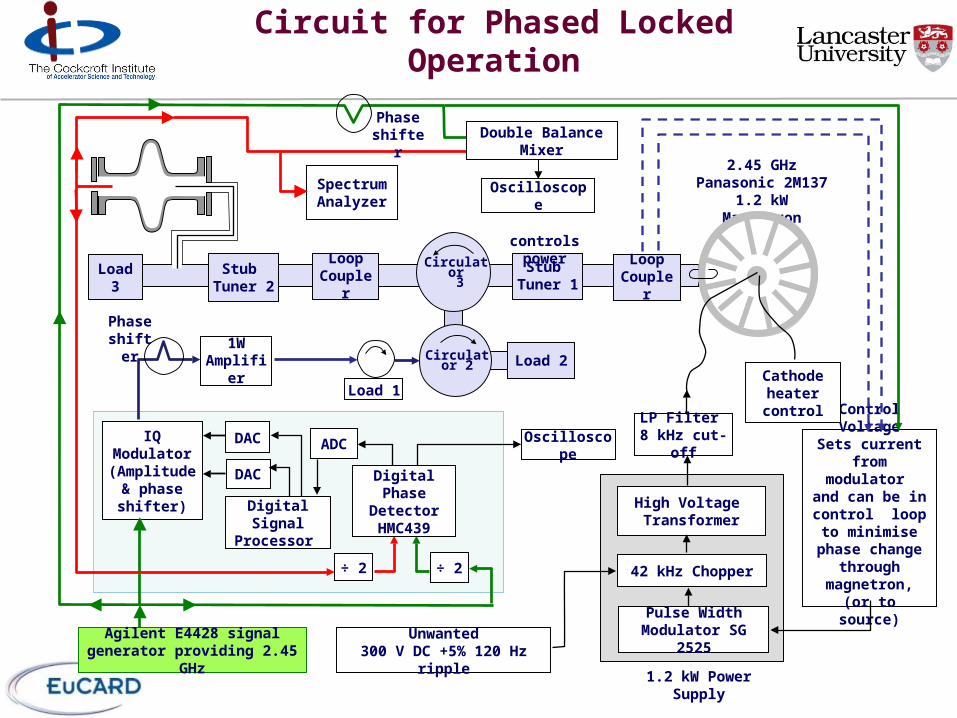
Circuit for Phased Locked Operation
1.2 kW Power Supply
1W Amplifier
Agilent E4428 signal generator providing 2.45 GHz
Load 2
Load 3
High Voltage Transformer
42 kHz Chopper
Pulse Width Modulator SG 2525
Stub Tuner 1
Circulator 3
Circulator 2
LP Filter 8 kHz cut-off
Unwanted300 V DC +5% 120 Hz ripple
2.45 GHz Panasonic 2M137 1.2 kW Magnetron
Loop Coupler
Stub Tuner 2
Oscilloscope
Load 1
Oscilloscope
÷ 2
ADCDACIQ Modulator(Amplitude &
phase shifter)
÷ 2
DAC
Digital Signal Processor
Digital Phase DetectorHMC439
Phase shifter
Spectrum Analyzer
Phase shifter
Control VoltageSets current
from modulator and can be in
control loop to minimise phase change through
magnetron,(or to source)
Cathode heater control
Loop Coupler
Double Balance Mixer
controls power
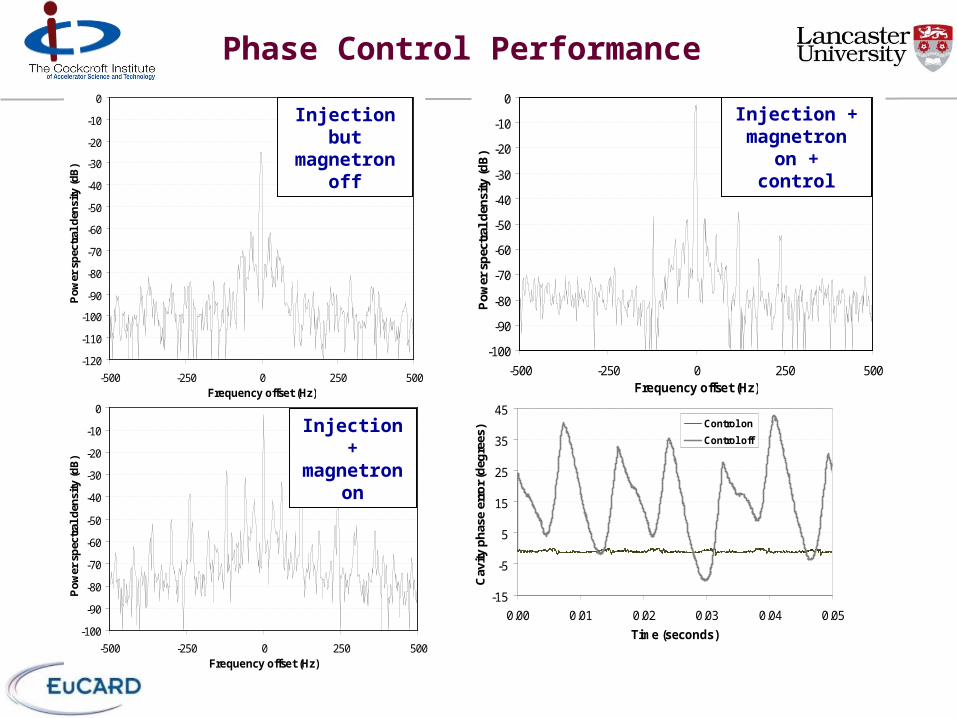
Phase Control Performance
-100
-90
-80
-70
-60
-50
-40
-30
-20
-10
0
-500 -250 0 250 500Frequency offset (Hz)
Po
wer
sp
ectr
al d
ensi
ty (
dB
)
-120
-110
-100
-90
-80
-70
-60
-50
-40
-30
-20
-10
0
-500 -250 0 250 500Frequency offset (Hz)
Po
wer
sp
ectr
al d
ensi
ty (
dB
)
-100
-90
-80
-70
-60
-50
-40
-30
-20
-10
0
-500 -250 0 250 500Frequency offset (Hz)
Po
wer
sp
ectr
al d
ensi
ty (
dB
)
-15
-5
5
15
25
35
45
0.00 0.01 0.02 0.03 0.04 0.05
Time (seconds)
Cav
ity p
has
e er
ror
(deg
rees
) Control on
Control off
Injection but magnetron
off
Injection +magnetron
on
Injection +magnetron on
+control

RF Interferometer
master oscillator
phase shifter
loop filter
directional coupler
Phase shifter
loop filter
directional coupler
digital phase detector
digital phase detector
coax link
synchronous output
synchronous output
Interferometer line length adjustment Precision reflector
Position along cable
Far location
Near locationtime
Synchronisation when return pulse arrives at time when outward pulse is sent
adjust effective position of far location with a phase shifter
180o
0o

VTF Phase Control Tests
~ 15 metrelow loss
(high power)
coax linkDivider
Rhode & Schwarz SG used to generate 3.9 GHz
Load
phase detector board B
divide to 1.3 GHzsynchronous
reference signals
phase shifter
precision reflector circuit
Phase shifter
interferometer line length adjustment circuits
Phase shifter
divide to 1.3 GHz
phase detector board A
Load Load
vector mod.
16 bit A/D
cavity control
D/A
DSPdoes IQ
conversion then PI control Loop
filter
Loop filter
Manual Phase Shifter
Manual phase shifter
Manual phase shifter
IF
Load LoadPower metersPower meters
DBM
vector mod.
16 bit A/D
cavity control
D/A
DSPdoes IQ
conversion then PI control
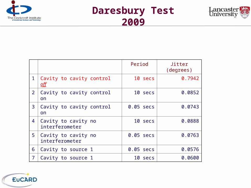
Daresbury Test 2009
Period Jitter (degrees)
1 Cavity to cavity control off 10 secs 0.7942
2 Cavity to cavity control on 10 secs 0.0852
3 Cavity to cavity control on 0.05 secs 0.0743
4 Cavity to cavity no interferometer 10 secs 0.0888
5 Cavity to cavity no interferometer 0.05 secs 0.0763
6 Cavity to source 1 0.05 secs 0.0576
7 Cavity to source 1 10 secs 0.0600
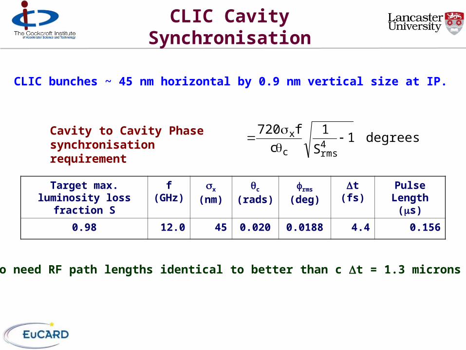
CLIC Cavity Synchronisation
Cavity to Cavity Phase synchronisation requirement
degrees1S
1
c
f7204rmsc
x
Target max. luminosity loss fraction S
f (GHz)
x
(nm)c
(rads)rms
(deg)t (fs) Pulse
Length (s)
0.98 12.0 45 0.020 0.0188 4.4 0.156
So need RF path lengths identical to better than c t = 1.3 microns
CLIC bunches ~ 45 nm horizontal by 0.9 nm vertical size at IP.
Particle Accelerator Engineering, London, October 2014
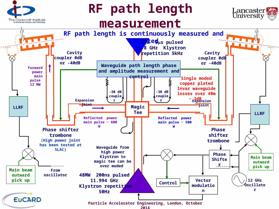
RF path length measurement
48MW 200ns pulsed 11.994 GHz Klystron
repetition 50Hz Vector
modulationControl
Phase Shifter
12 GHz Oscillator
Main beam outward pick up
Main beam outward pick up
From oscillator
Phase shifter trombone
(High power joint has been tested at SLAC)
Magic Tee
Waveguide path length phase and amplitude measurement and control
4kW 5s pulsed 11.8 GHz Klystron
repetition 5kHz
LLRF
Phase shifter trombone
LLRF
Cavity coupler 0dB or -40dB
Cavity coupler 0dB or -40dB
Expansion joint
Single moded copper plated Invar waveguide losses over 40m ~ 3dB -30 dB
coupler -30 dB coupler
Forward power
main pulse
12 MW
Reflected power main pulse ~ 600 W
Reflected power main pulse ~ 500 W
Waveguide from high power Klystron to magic tee can be
over moded
Expansion joint
RF path length is continuously measured and adjusted
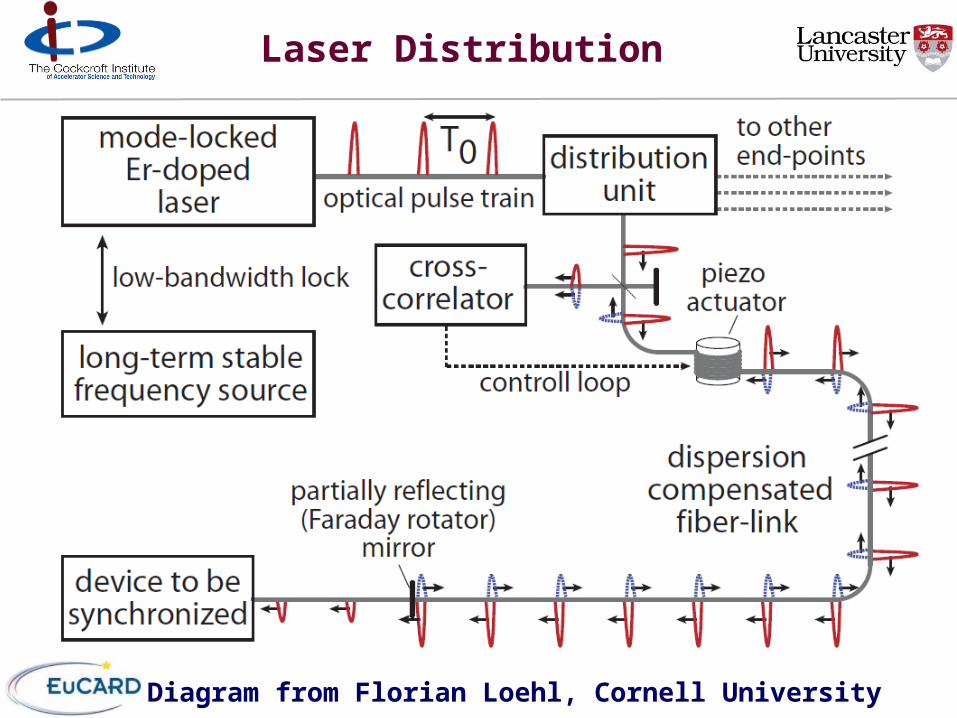
Laser Distribution
Diagram from Florian Loehl, Cornell University
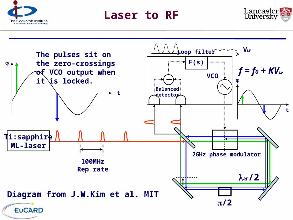
Laser to RF
RF/2
f = f0 + KVLF
2GHz phase modulator
Ti:sapphireML-laser
F(s)
Loop filter
t
VCO
Balanceddetector
VLF
/2
100MHzRep rate
t
The pulses sit onthe zero-crossingsof VCO output when it is locked.
Diagram from J.W.Kim et al. MIT