Embed Size (px)
Citation preview
:
Particle Velocimetry and Photoelasticity Applied to theStudy of Dynamic Sliding Along Frictionally-HeldBimaterial Interfaces: Techniques and Feasibility
G. Lykotrafitis & A.J. Rosakis & G. Ravichandran
Received: 3 August 2005 /Accepted: 21 November 2005# Society for Experimental Mechanics 2006
Abstract A laser interferometry-based technique was
developed to locally measure the in-plane components
of particle velocity in dynamic experiments. This
technique was applied in the experimental investiga-
tion of dynamic sliding along the incoherent (friction-
al) interface of a Homalite–steel bimaterial structure.
The bimaterial specimen was subjected to uniform
compressive stress and impact-induced shear loading.
The evolution of the dynamic stress field was recorded
by high-speed photography in conjunction with dy-
namic photoelasticity. The combination of the full-field
technique of photoelasticity with the local technique of
velocimetry was proven to be a very powerful tool in
the investigation of dynamic sliding. A relatively broad
loading wave with an eye-like structure emanated from
the interface. The particle velocity measurements
established that sliding started behind the eye-like
fringe pattern. It propagated with supershear speed
with respect to Homalite. A shear Mach line originat-
ing from the sliding tip is visible in the photoelastic
images. A vertical particle velocity measurement re-
vealed the existence of a wrinkle-like pulse traveling
along the bimaterial interface. The wrinkle-like pulse
followed the initial shear rupture tip and propagated at
a specific subshear speed.
Keywords Dynamic frictional sliding .
Incoherent interface . Bimaterial system .
Photoelasticity . In-plane velocity measurement .
Supershear rupture . Subshear wrinkle-like pulse
Introduction
The measurement of the in-plane components of
particle velocity is a challenging problem in experi-
mental mechanics and only a few attempts have been
made to address it [14–18]. In this paper, a relatively
simple, but very accurate, technique is introduced for
measuring the in-plane (horizontal and vertical) and
the out-of-plane components of particle velocity in
dynamic experiments. After the technique is estab-
lished, it is applied to the investigation of dynamic
sliding along incoherent (frictionally-held) interfaces
of bimaterial systems.
Earlier interest on dynamic failure processes along
bimaterial interfaces has been focused on the case of
coherent interfaces (bonded interfaces of finite strength
and toughness). However, many composite structures in
various engineering applications (e.g., bolted joints and
sandwich structures) consist of layers of different
materials held together by applied pressure without
any bond between the contact faces. In order to utilize
these layered structures effectively, the failure process
along their incoherent interfaces is the key problem to
be investigated. Here, we confine our attention to the
failure process generated by impact shear loading.
Unlike the case of coherent interfaces, where the
resistance to failure through sliding is related to the
strength and toughness of the bond between the plates,
in the incoherent case the resistance to sliding comes
from the frictional stresses between the surfaces in
contact.
There are two approaches to describing frictional
sliding. The most classical approach uses elastody-
namic shear crack models (behind the leading edge of
Experimental Mechanics (2006) 46: 205–216
DOI 10.1007/s11340-006-6418-4
G. Lykotrafitis (), SEM member) I A.J Rosakis(SEM member) I G. Ravichandram (SEM member)California Institute of Technology, California, USAe-mail: [email protected]
SEM
sliding, the surfaces slide continuously and interact
through contact and friction). More recently, models
that describe sliding as Fself-healing_ slip pulse have
been introduced (behind the leading edge of the
sliding, there is sliding for a finite length followed by
surface locking).
Classic dynamic fracture theories [1, 2] of growing
shear cracks have many similarities to the frictional
sliding process. These theories treat the rupture front
as a distinct point (sharp-tip crack). The crack-like
rupture of coherent interfaces, separating similar and
dissimilar solids subjected to dynamic shear loading,
has been the subject of extensive experimental,
numerical and analytical investigations in the past
years and was summarized by Rosakis [3] in a recent
review. Of relevance to the present study is the
persistent occurrence of intersonic shear rupture along
coherent bimaterial interfaces [4 – 9].
Theoretical and numerical investigations [10–12]
have shown that incoherent interfaces of compressed
bimaterial structures can sustain interface waves in-
volving separation (wrinkle-like pulses). Particle dis-
placement in a direction perpendicular to the interface
is greater in the slower material than in the faster
material; that may result in a local separation of the
interface during sliding. Wrinkle-like pulses have also
been observed experimentally in rubber sliding experi-
ments [13]. We note that the wrinkle-like pulses
propagate at a speed between the Rayleigh wave
speed and the shear wave speed of the slower material
and are different from the Schallamach waves which
are very slow compared to the wave speeds of the
involved materials.
In this paper, laser interferometry-based velocim-
etry is combined with dynamic photoelasticity to
record frictional sliding events at incoherent interfaces
of bimaterial systems in a microsecond time scale.
Pairs of rectangular Homalite and steel plates are
used. A uniform external compressive stress is applied
to the bimaterial specimen via a hydraulic press.
Asymmetric impact loading is imposed using a gas
gun and a steel projectile. The fringe pattern evolution
in conjunction with the sliding velocity history gives
direct evidence of the sliding mode, the existence of a
supersonic disturbance with respect to Homalite, the
exact point of sliding initiation and the sliding propa-
gation speed. Strong evidence of a wrinkle-like pulse
traveling along the interface is also recorded. The re-
sults presented here show that under certain loading
conditions the failure of bimaterial structures sub-
jected to impact shear loading can take the form of a
supershear crack-like sliding, followed by a local open-
ing displacement in the form of a wrinkle-like pulse.
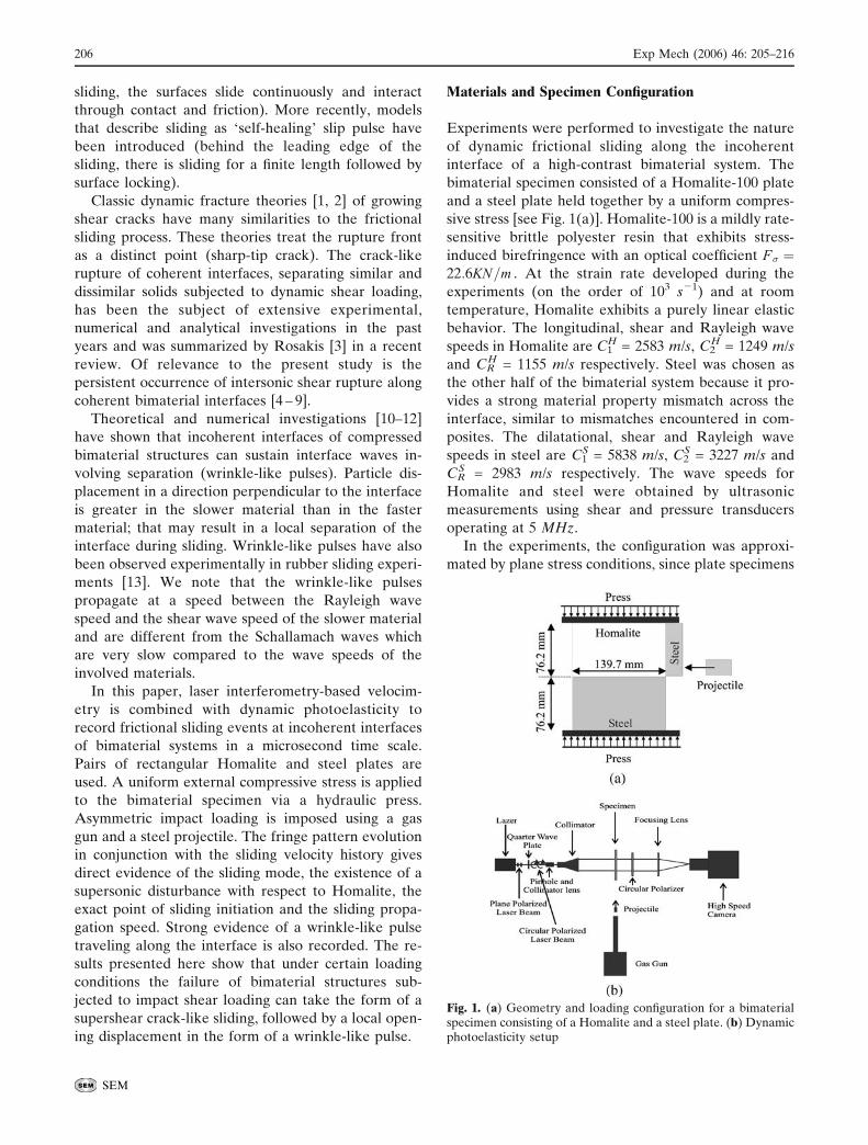
Materials and Specimen Configuration
Experiments were performed to investigate the nature
of dynamic frictional sliding along the incoherent
interface of a high-contrast bimaterial system. The
bimaterial specimen consisted of a Homalite-100 plate
and a steel plate held together by a uniform compres-
sive stress [see Fig. 1(a)]. Homalite-100 is a mildly rate-
sensitive brittle polyester resin that exhibits stress-
induced birefringence with an optical coefficient F� ¼22:6KN=m . At the strain rate developed during the
experiments (on the order of 103 sj1) and at room
temperature, Homalite exhibits a purely linear elastic
behavior. The longitudinal, shear and Rayleigh wave
speeds in Homalite are C1H = 2583 m/s, C2
H = 1249 m/s
and CRH = 1155 m/s respectively. Steel was chosen as
the other half of the bimaterial system because it pro-
vides a strong material property mismatch across the
interface, similar to mismatches encountered in com-
posites. The dilatational, shear and Rayleigh wave
speeds in steel are C1S = 5838 m/s, C2
S = 3227 m/s and
CRS = 2983 m/s respectively. The wave speeds for
Homalite and steel were obtained by ultrasonic
measurements using shear and pressure transducers
operating at 5 MHz.
In the experiments, the configuration was approxi-
mated by plane stress conditions, since plate specimens
Fig. 1. (a) Geometry and loading configuration for a bimaterialspecimen consisting of a Homalite and a steel plate. (b) Dynamicphotoelasticity setup
206 Exp Mech (2006) 46: 205–216
SEM
76.2 mm high, 139.7 mm long and 9.525 mm thick were
employed. The shear wave speeds are identical in 3-D
and for the plane stress approximation. The same is
true for the Rayleigh wave speed, since the contribu-
tion in the Rayleigh wave formation comes primarily
from the shear wave. However, the plane stress
longitudinal wave speeds of Homalite-100 and steel
are CH1� ¼ 2187m=s; CS
1� ¼ 5378m=s respectively.
Experimental Setup and Procedure
A combination of two experimental techniques was
used in this investigation. Dynamic Photoelasticity,
which gives the full field maximum shear stress dis-
tribution, was used in conjunction with a new tech-
nique based on laser interferometry. This technique
provides a continuous local measurement of the hor-
izontal and vertical components of the relative velocity
of two adjacent points across the bimaterial interface.
The initiation and evolution of sliding was explored
through photoelasticity and velocimetry at a micro-
second time scale.
The compressive stress was applied with a press
calibrated using a load cell. The asymmetric impact
loading was imposed via a cylindrical steel projectile
with a diameter of 25 mm and a length of 51 mm, fired
by a gas gun. A steel buffer 73 mm high, 25.4 mm long
and 9.525 mm thick was attached to the impact side of
the Homalite plate to prevent shattering and to induce
a more or less planar loading wave.
Dynamic Photoelasticity Setup
A typical experimental setup for dynamic photoelas-
ticity experiments is shown in Fig. 1(b). The optical
setup was arranged for a light field. Isochromatic
fringes are contours of maximum in-plane shear stress
Cmax governed by the stress optical law
2Cmax ¼ �1 � �2 ¼ NF�=h
where F� is the material’s stress optical coefficient,
h is the specimen thickness, A1, A2 are the principal
stresses and N = n + 1/2 (with n = 0, 1, 2, . . .) is the
isochromatic fringe order. A continuous laser was used
as the light source in our experiments. The laser was
set to operate on a single wave length of 540 nm (green
light). It emitted an intense beam of 2 mm in diameter
and 100:1 vertically polarized. The laser beam first
passed through a quarter wave plate, which trans-
formed it into a circular polarized beam. Then it
passed through a 6 2m pinhole and a collimator lens.
Finally, the coherent monochromatic circular polar-
ized light went through a collimator lens and expanded
in a uniform laser beam of 130 mm diameter. The laser
beam was transmitted through the specimen and an
analyzer. The resulting photoelastic fringe pattern was
recorded with a high-speed digital camera (Cordin
model 220), which is able to record 16 distinct frames
at framing rates up to 100 million frames per second.
In this experimental work, most of the high-speed
photography was performed at 250,000 to 1,000,000
frames per second. The field of view was wide enough
to cover most of the specimen.
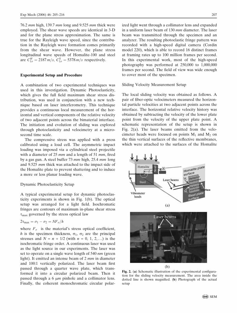
Sliding Velocity Measurement Setup
The local sliding velocity was obtained as follows. A
pair of fiber-optic velocimeters measured the horizon-
tal particle velocities at two adjacent points across the
interface. The horizontal relative velocity history was
obtained by subtracting the velocity of the lower plate
point from the velocity of the upper plate point. A
schematic representation of the setup is shown in
Fig. 2(a). The laser beams emitted from the velo-
cimeter heads were focused on points M1 and M2 on
the thin vertical surfaces of the reflective membranes,
which were attached to the surfaces of the Homalite
Fig. 2. (a) Schematic illustration of the experimental configura-tion for the sliding velocity measurement. The area inside thedotted line is shown magnified. (b) Photograph of the actualsetup
Exp Mech (2006) 46: 205–216 207
SEM
(top) and steel (bottom) plates respectively. The
distance of each point from the interface was less than
250 2m before compression, and both points had the
same horizontal distance from the impact side of the
Homalite plates. A picture of the actual setup is
presented in Fig. 2(b). The velocimeter and its use in
measuring the in-plane components of a particle
velocity are described in detail in the next section.
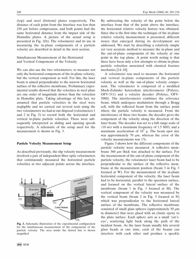
Simultaneous Measurement of the Horizontal
and Vertical Components of the Velocity
We can also use the two velocimeters, to measure not
only the horizontal component of the in-plane velocity,
but the vertical component as well. For this, the laser
beam is aimed perpendicular to the narrow horizontal
surface of the reflective membrane. Preliminary exper-
imental results showed that the velocities in steel plate
are one order of magnitude slower than the velocities
in Homalite plate. Taking advantage of this fact, we
assumed that particle velocities in the steel were
negligible and we carried out several tests using the
two velocimeters we had at our disposal (velocimeters 1
and 2 in Fig. 3) to record both the horizontal and
vertical in-plane particle velocities. These were sub-
sequently interpreted as sliding and opening speeds
respectively. A schematic of the setup used for the
measurement is shown in Fig. 3.
Particle Velocity Measurement Setup
As described previously, the slip velocity measurement
involved a pair of independent fiber-optic velocimeters
that continuously measured the horizontal particle
velocities at two adjacent points across the interface.
By subtracting the velocity of the point below the
interface from that of the point above the interface,
the horizontal relative velocity history was obtained.
Since this is the first time the technique of the in-plane
relative velocity measurement is presented, different
issues that emerged during its development are
addressed. We start by describing a relatively simple
yet very accurate method to measure the in-plane and
the out-of-plane components of the velocity at one
point in the top plane. A point worth noting is that
there have been only a few attempts to obtain in-plane
particle velocities associated with classical fracture
mechanics [14–18].
A velocimeter was used to measure the horizontal
and vertical in-plane components of the particle
velocity as well as the out-of-plane velocity compo-
nent. The velocimeter is composed of a modified
Mach-Zehnder heterodyne interferometer (Polytec,
OFV-511) and a velocity decoder (Polytec, OFV-
5000). The interferometer combines the reference
beam, which undergoes modulation through a Bragg
cell, with the reflected beam from the surface point
where the particle velocity is measured. From the
interference of these two beams, the decoder gives the
component of the velocity along the direction of the
laser beam. The decoder was set to a full range scale of
T10 m/s with a maximum frequency of 1.5 MHz and a
maximum acceleration of 107 g. The beam spot size
was approximately 70 2m, whereas the error of the
velocity measurements was 1%.
Figure 3 shows how the different components of the
particle velocity were measured. A reflective mem-
brane 360 2m thick was attached to the surface. For
the measurement of the out-of-plane component of the
particle velocity, the velocimeter laser beam had to be
perpendicular to the surface of the reflective mem-
brane at the measurement position (beam 3 in Fig. 3
focused at W). For the measurement of the in-plane
horizontal component of the velocity, the laser beam
had to be horizontal, parallel to the specimen surface,
and focused on the vertical lateral surface of the
membrane (beam 1 in Fig. 3 focused at M). The
vertical component of the velocity was measured by
the vertical beam (beam 2 in Fig. 3 focused at N)
which was perpendicular to the horizontal lateral
surface of the membrane. The reflective membrane
consisted of small glass spheres (approximately 50 2m
in diameter) that were glued with an elastic epoxy to
the plate surface. Each sphere acts as a small Fcat_s-
eye_, scattering light back along the path of the
incident beam. As the laser beam usually hits several
glass beads at one time, each of the beams can
interfere with each other and produce a speckle
Fig. 3. Schematic illustration of the experimental configurationfor the simultaneous measurement of the components of theparticle velocity. The area inside the dotted line is shownmagnified
208 Exp Mech (2006) 46: 205–216
SEM
pattern. If the focused spot is very small, as it was in
the presenting experiments, the number of scattering
centers is small and the angular dependence of the
path length differences in a given direction is also
small. This leads to a large solid angle over which the
interference condition is reasonably constant and the
speckle noise is small. In the experiments, the devia-
tion of the laser beams from the normal direction to
the corresponding membrane surface was approxi-
mately 2- to 3-, and an excellent quality signal was
received from the velocimeter. This amount of devia-
tion angle did not affect the results, as we demonstrate
below.
Reliability of the Proposed Technique
As previously mentioned, two independent velocime-
ters were employed in the experiments. We first
verified that both instruments were calibrated. To this
end, we simultaneously measured the out of plane
component of the velocity of the same point by the two
velocimeters. Both instruments gave exactly the same
result.
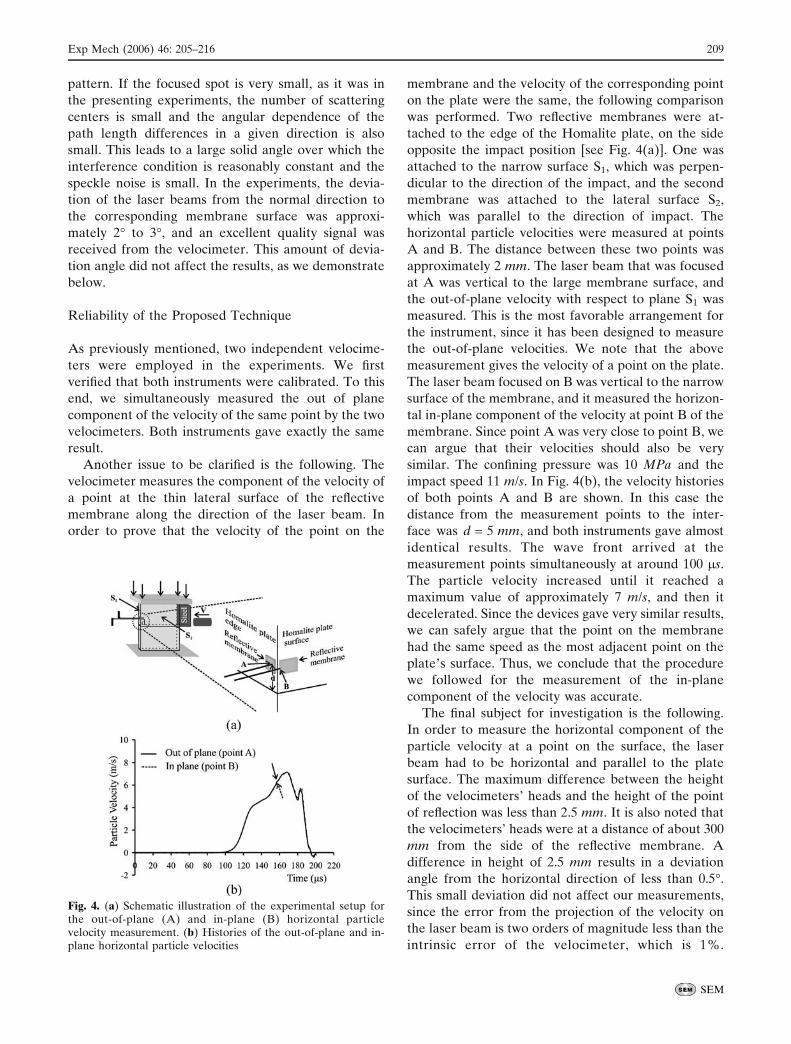
Another issue to be clarified is the following. The
velocimeter measures the component of the velocity of
a point at the thin lateral surface of the reflective
membrane along the direction of the laser beam. In
order to prove that the velocity of the point on the
membrane and the velocity of the corresponding point
on the plate were the same, the following comparison
was performed. Two reflective membranes were at-
tached to the edge of the Homalite plate, on the side
opposite the impact position [see Fig. 4(a)]. One was
attached to the narrow surface S1, which was perpen-
dicular to the direction of the impact, and the second
membrane was attached to the lateral surface S2,
which was parallel to the direction of impact. The
horizontal particle velocities were measured at points
A and B. The distance between these two points was
approximately 2 mm. The laser beam that was focused
at A was vertical to the large membrane surface, and
the out-of-plane velocity with respect to plane S1 was
measured. This is the most favorable arrangement for
the instrument, since it has been designed to measure
the out-of-plane velocities. We note that the above
measurement gives the velocity of a point on the plate.
The laser beam focused on B was vertical to the narrow
surface of the membrane, and it measured the horizon-
tal in-plane component of the velocity at point B of the
membrane. Since point A was very close to point B, we
can argue that their velocities should also be very
similar. The confining pressure was 10 MPa and the
impact speed 11 m/s. In Fig. 4(b), the velocity histories
of both points A and B are shown. In this case the
distance from the measurement points to the inter-
face was d = 5 mm, and both instruments gave almost
identical results. The wave front arrived at the
measurement points simultaneously at around 100 2s.
The particle velocity increased until it reached a
maximum value of approximately 7 m/s, and then it
decelerated. Since the devices gave very similar results,
we can safely argue that the point on the membrane
had the same speed as the most adjacent point on the
plate_s surface. Thus, we conclude that the procedure
we followed for the measurement of the in-plane
component of the velocity was accurate.
The final subject for investigation is the following.
In order to measure the horizontal component of the
particle velocity at a point on the surface, the laser
beam had to be horizontal and parallel to the plate
surface. The maximum difference between the height
of the velocimeters_ heads and the height of the point
of reflection was less than 2.5 mm. It is also noted that
the velocimeters’ heads were at a distance of about 300
mm from the side of the reflective membrane. A
difference in height of 2.5 mm results in a deviation
angle from the horizontal direction of less than 0.5-.
This small deviation did not affect our measurements,
since the error from the projection of the velocity on
the laser beam is two orders of magnitude less than the
intrinsic error of the velocimeter, which is 1%.
Fig. 4. (a) Schematic illustration of the experimental setup forthe out-of-plane (A) and in-plane (B) horizontal particlevelocity measurement. (b) Histories of the out-of-plane and in-plane horizontal particle velocities
Exp Mech (2006) 46: 205–216 209
SEM
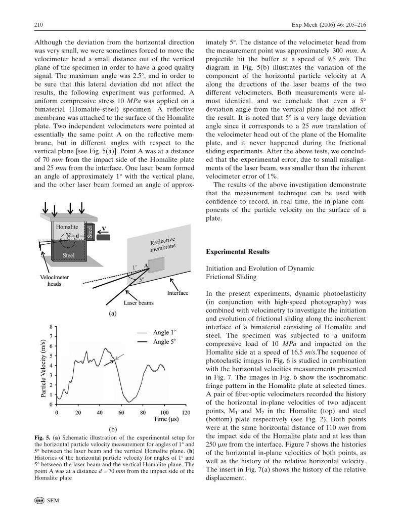
Although the deviation from the horizontal direction
was very small, we were sometimes forced to move the
velocimeter head a small distance out of the vertical
plane of the specimen in order to have a good quality
signal. The maximum angle was 2.5-, and in order to
be sure that this lateral deviation did not affect the
results, the following experiment was performed. A
uniform compressive stress 10 MPa was applied on a
bimaterial (Homalite-steel) specimen. A reflective
membrane was attached to the surface of the Homalite
plate. Two independent velocimeters were pointed at
essentially the same point A on the reflective mem-
brane, but in different angles with respect to the
vertical plane [see Fig. 5(a)]. Point A was at a distance
of 70 mm from the impact side of the Homalite plate
and 25 mm from the interface. One laser beam formed
an angle of approximately 1- with the vertical plane,
and the other laser beam formed an angle of approx-
imately 5-. The distance of the velocimeter head from
the measurement point was approximately 300 mm. A
projectile hit the buffer at a speed of 9.5 m/s. The
diagram in Fig. 5(b) illustrates the variation of the
component of the horizontal particle velocity at A
along the directions of the laser beams of the two
different velocimeters. Both measurements were al-
most identical, and we conclude that even a 5-
deviation angle from the vertical plane did not affect
the result. It is noted that 5- is a very large deviation
angle since it corresponds to a 25 mm translation of
the velocimeter head out of the plane of the Homalite
plate, and it never happened during the frictional
sliding experiments. After the above tests, we conclud-
ed that the experimental error, due to small misalign-
ments of the laser beam, was smaller than the inherent
velocimeter error of 1%.
The results of the above investigation demonstrate
that the measurement technique can be used with
confidence to record, in real time, the in-plane com-
ponents of the particle velocity on the surface of a
plate.
Experimental Results
Initiation and Evolution of Dynamic
Frictional Sliding
In the present experiments, dynamic photoelasticity
(in conjunction with high-speed photography) was
combined with velocimetry to investigate the initiation
and evolution of frictional sliding along the incoherent
interface of a bimaterial consisting of Homalite and
steel. The specimen was subjected to a uniform
compressive load of 10 MPa and impacted on the
Homalite side at a speed of 16.5 m/s.The sequence of
photoelastic images in Fig. 6 is studied in combination
with the horizontal velocities measurements presented
in Fig. 7. The images in Fig. 6 show the isochromatic
fringe pattern in the Homalite plate at selected times.
A pair of fiber-optic velocimeters recorded the history
of the horizontal in-plane velocities of two adjacent
points, M1 and M2 in the Homalite (top) and steel
(bottom) plate respectively (see Fig. 2). Both points
were at the same horizontal distance of 110 mm from
the impact side of the Homalite plate and at less than
250 2m from the interface. Figure 7 shows the histories
of the horizontal in-plane velocities of both points, as
well as the history of the relative horizontal velocity.
The insert in Fig. 7(a) shows the history of the relative
displacement.
Fig. 5. (a) Schematic illustration of the experimental setup forthe horizontal particle velocity measurement for angles of 1- and5- between the laser beam and the vertical Homalite plane. (b)Histories of the horizontal particle velocity for angles of 1- and5- between the laser beam and the vertical Homalite plane. Thepoint A was at a distance d = 70 mm from the impact side of theHomalite plate
210 Exp Mech (2006) 46: 205–216
SEM
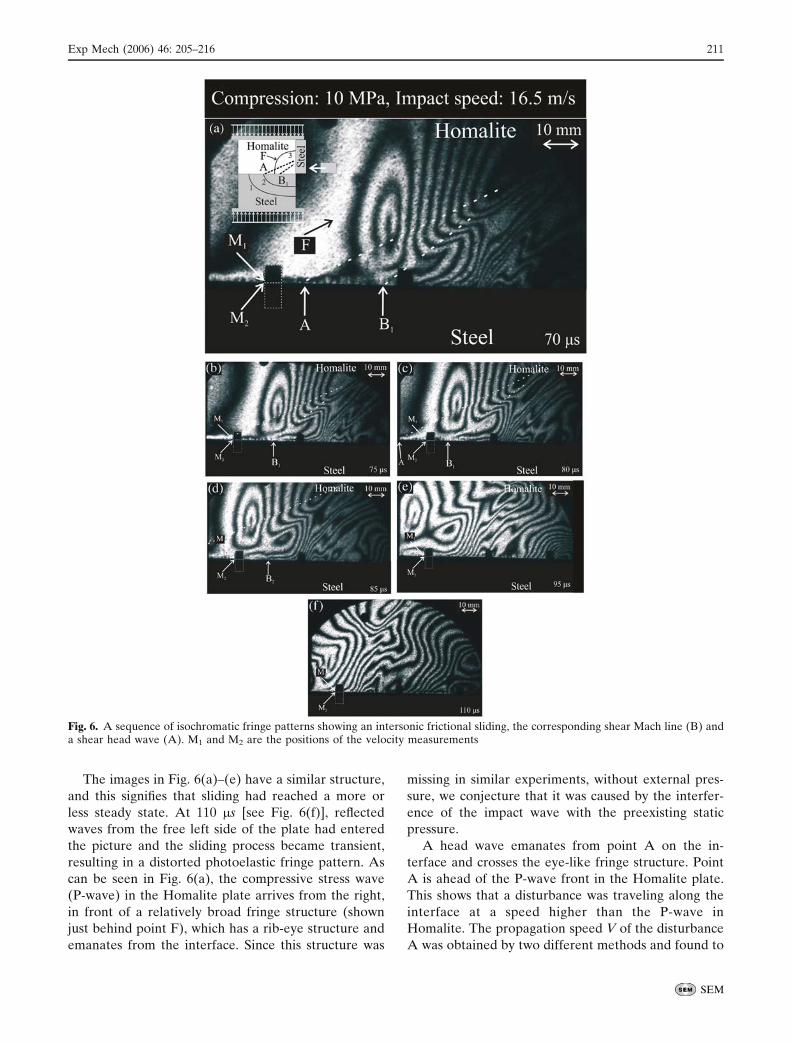
The images in Fig. 6(a)–(e) have a similar structure,
and this signifies that sliding had reached a more or
less steady state. At 110 2s [see Fig. 6(f)], reflected
waves from the free left side of the plate had entered
the picture and the sliding process became transient,
resulting in a distorted photoelastic fringe pattern. As
can be seen in Fig. 6(a), the compressive stress wave
(P-wave) in the Homalite plate arrives from the right,
in front of a relatively broad fringe structure (shown
just behind point F), which has a rib-eye structure and
emanates from the interface. Since this structure was
missing in similar experiments, without external pres-
sure, we conjecture that it was caused by the interfer-
ence of the impact wave with the preexisting static
pressure.
A head wave emanates from point A on the in-
terface and crosses the eye-like fringe structure. Point
A is ahead of the P-wave front in the Homalite plate.
This shows that a disturbance was traveling along the
interface at a speed higher than the P-wave in
Homalite. The propagation speed V of the disturbance
A was obtained by two different methods and found to
Fig. 6. A sequence of isochromatic fringe patterns showing an intersonic frictional sliding, the corresponding shear Mach line (B) anda shear head wave (A). M1 and M2 are the positions of the velocity measurements
Exp Mech (2006) 46: 205–216 211
SEM
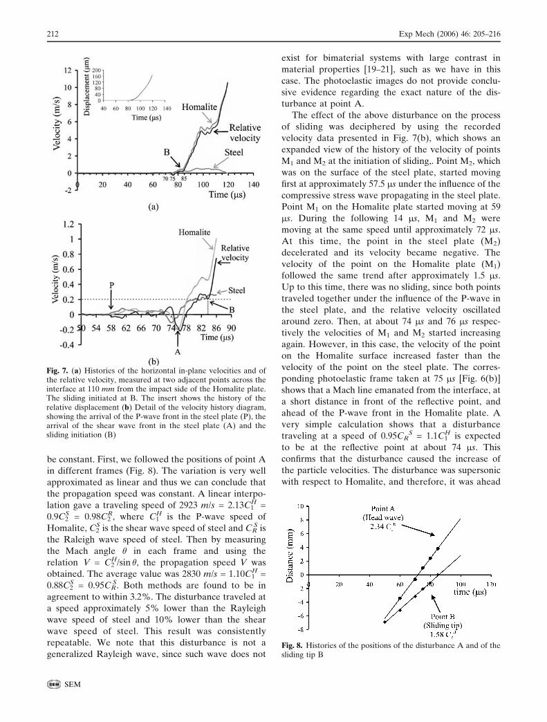
be constant. First, we followed the positions of point A
in different frames (Fig. 8). The variation is very well
approximated as linear and thus we can conclude that
the propagation speed was constant. A linear interpo-
lation gave a traveling speed of 2923 m/s = 2.13C1H =
0.9C2S = 0.98C2
R, where C1H is the P-wave speed of
Homalite, C2S is the shear wave speed of steel and CR
S is
the Raleigh wave speed of steel. Then by measuring
the Mach angle � in each frame and using the
relation V = C2H/sin �, the propagation speed V was
obtained. The average value was 2830 m/s = 1.10C1H =
0.88C2S = 0.95CR
S. Both methods are found to be in
agreement to within 3.2%. The disturbance traveled at
a speed approximately 5% lower than the Rayleigh
wave speed of steel and 10% lower than the shear
wave speed of steel. This result was consistently
repeatable. We note that this disturbance is not a
generalized Rayleigh wave, since such wave does not
exist for bimaterial systems with large contrast in
material properties [19–21], such as we have in this
case. The photoelastic images do not provide conclu-
sive evidence regarding the exact nature of the dis-
turbance at point A.
The effect of the above disturbance on the process
of sliding was deciphered by using the recorded
velocity data presented in Fig. 7(b), which shows an
expanded view of the history of the velocity of points
M1 and M2 at the initiation of sliding,. Point M2, which
was on the surface of the steel plate, started moving
first at approximately 57.5 2s under the influence of the
compressive stress wave propagating in the steel plate.
Point M1 on the Homalite plate started moving at 59
2s. During the following 14 2s, M1 and M2 were
moving at the same speed until approximately 72 2s.
At this time, the point in the steel plate (M2)
decelerated and its velocity became negative. The
velocity of the point on the Homalite plate (M1)
followed the same trend after approximately 1.5 2s.
Up to this time, there was no sliding, since both points
traveled together under the influence of the P-wave in
the steel plate, and the relative velocity oscillated
around zero. Then, at about 74 2s and 76 2s respec-
tively the velocities of M1 and M2 started increasing
again. However, in this case, the velocity of the point
on the Homalite surface increased faster than the
velocity of the point on the steel plate. The corres-
ponding photoelastic frame taken at 75 2s [Fig. 6(b)]
shows that a Mach line emanated from the interface, at
a short distance in front of the reflective point, and
ahead of the P-wave front in the Homalite plate. A
very simple calculation shows that a disturbance
traveling at a speed of 0.95CRS = 1.1C1
H is expected
to be at the reflective point at about 74 2s. This
confirms that the disturbance caused the increase of
the particle velocities. The disturbance was supersonic
with respect to Homalite, and therefore, it was ahead
Fig. 8. Histories of the positions of the disturbance A and of thesliding tip B
Fig. 7. (a) Histories of the horizontal in-plane velocities and ofthe relative velocity, measured at two adjacent points across theinterface at 110 mm from the impact side of the Homalite plate.The sliding initiated at B. The insert shows the history of therelative displacement (b) Detail of the velocity history diagram,showing the arrival of the P-wave front in the steel plate (P), thearrival of the shear wave front in the steel plate (A) and thesliding initiation (B)
212 Exp Mech (2006) 46: 205–216
SEM
of the P-wave front traveling in the Homalite plate. In
addition, a Mach cone was formed with a tip at the
disturbance. The initial impact of the projectile on the
steel buffer created a compression P-wave, transmitted
into the Homalite plate. Because of friction, some of
the energy also transmitted into the steel plate. The P-
wave traveled faster in the steel plate than in the
Homalite plate, and thus, a precursor effect emerged.
Nevertheless, photoelasticity is not very sensitive to
compression, and because of this we could not see a
possible Mach cone associated with the interface
disturbance traveling at the steel P-wave speed. The
disturbance, however, caused the photoelastic fringe
pattern to warp enough for it to be captured by the high
speed camera. The insert in Fig. 6(a) schematically
illustrates the loading configuration, the resulting wave
fronts, the shear head wave and the supershear sliding
tip with the resulting Mach cone. Curves 1, 2 and 3
correspond to the P-wave front in the steel plate, shear
wave front in the steel plate and the P-wave front in the
Homalite plate. Point A represents the disturbance, just
behind the shear wave front in the steel plate, and point
B represents the sliding tip.
In Fig. 6(c), the tip of the first Mach line has passed
the position of velocity measurement, whereas the eye-
like structure has just arrived there. The velocimeter
recording shows that at approximately 76 2s the
relative horizontal velocity between M1 and M2 has
increased, but not very sharply. We also note that the
numerically calculated relative horizontal displace-
ment between the points M1 and M2 was less than
1 2m until 84 2s. This indicates that until 84 2s there
was no sliding, but only shear elastic deformation of
the material close to the interface (material between
M1 and M2. Thus, the disturbance and the eye-like
fringe structure did not create slip.
However, at approximately 84 2s, a drastic change
occurred in the relative velocity and in the relative
displacement [see Fig. 7(a)]. The velocity of the
measurement point in the Homalite plate increased
rapidly, whereas the velocity of the point in the steel
plate remained almost constant. This resulted in a very
steep rise in the relative velocity and in a very abrupt
change in the slope of the relative displacement vs.
time diagram. We conclude that the sliding, at the
position of measurement, started at around 84 2s. The
corresponding photoelastic frame [see Fig. 6(d)]
captured at 85 2s is extremely revealing, in which a
fringe concentration point [point B of Fig. 6(a) and
(b)] coincided with the measurement position. It is
the sliding tip, and because it propagated with a
supershear speed, a Mach line emanated from this
position. Indeed, following the positions of the tip in
different frames (see Fig. 8) and using a linear
interpolation, we obtained the tip propagation velocity
which was 1970 m/s = 1.58C2H, higher than the shear
wave speed of Homalite.
The velocimeter measurement [Fig. 7(a)] shows that
the speed increased sharply from 84 2s to ap-
proximately 98 2s, and then it remained almost
constant until 110 2s, where a second acceleration
event happened. The time instance of 98 2s (when the
acceleration ceased) corresponded to a fringe concen-
tration point C [see Fig. 6(d)]. After point C, the
fringes were parallel to the interface, which means that
a constant maximum shear stress field was formed. In
Fig. 6(f), captured at 110 2s, the area of the photoe-
lastic pattern with inclined fringes arrived at the
measurement position, and this coincided with the ini-
tiation of the secondary acceleration caused by the
arrival of the reflected waves from the free side of
the Homalite plate. From the relative velocity history
diagram, we conclude that sliding was continuous
during the recording time. This means that sliding
occurred in a crack-like mode.
The above exhaustive study of the experimental
results clearly shows the power of the proposed point
velocity measurement in combination with the full
field technique of photoelasticity. We were able to
completely identify the different fringe formations in
the photoelastic images and explicitly connect them to
the changes in sliding velocity. We finally note that,
after the initiation of sliding, the in-plane horizontal
particle velocity in the steel plate was one order of
magnitude lower than the velocity in the Homalite
plate. This is true not only for the experiment analyzed
above, but for all of the performed experiments using
Homalite - steel bimaterial specimens.
The findings of this experiment are similar to results
obtained by experiments on crack growth in bimate-
rials [22–24]. We note that the first observations of
intersonically traveling cracks were made in connec-
tion with crack propagation along the interface of
bimaterial systems [4–9]. The main difference between
the experimental setups involved in crack growth ex-
periments and the setup we used for the sliding is as
follows: in the case of crack propagation, the Homalite
and steel plates were bonded together and a notch was
machined along the bond line at one edge. Thus, the
resistance to rupture was generated mainly from the
bond. In our case, the resistance to sliding was due to
the frictional stress between the surfaces of the two
plates. We also note that the frictional resistance was
not uniform along the interface and not constant with
time, since the dynamic compression and the sliding
velocity were changing with position and time.
Exp Mech (2006) 46: 205–216 213
SEM
Observation of Wrinkle-Like Pulses
Our goal in this section is to detect possible wrinkle-
like pulses propagating along the interface. Prelimi-
nary results showed that, as the confining stress
decreased and the impact speed increased, a charac-
teristic fringe structure emanated from the interface,
behind the sliding tip. The propagation speed of this
fringe structure was always between the Rayleigh
wave speed and the shear wave speed of Homalite,
within an experimental error. The above speed limits
are consistent with the theoretically predicted speed
limits of the wrinkle-like pulses [10]. Velocimetry was
used to obtain the vertical displacement caused by the
wrinkle-like pulse related to the mentioned fringe
structure and thus to infer any separation of the
surfaces in contact occurred during the sliding event.
In the experimental result presented in the previous
section, the particle velocities in the steel plate were
one order of magnitude less than the velocities in
Homalite plate. Taking advantage of this fact, we used
two velocimeters to record both the horizontal and
vertical in-plane components of the velocity at a point
on the Homalite plate, very close to the interface
(velocimeters 1 and 2 in Fig. 3). We then interpreted
our measurements as Bsliding’’ and Bopening’’ speeds
by assuming that the steel plate is effectively rigid
compared to the Homalite plate.
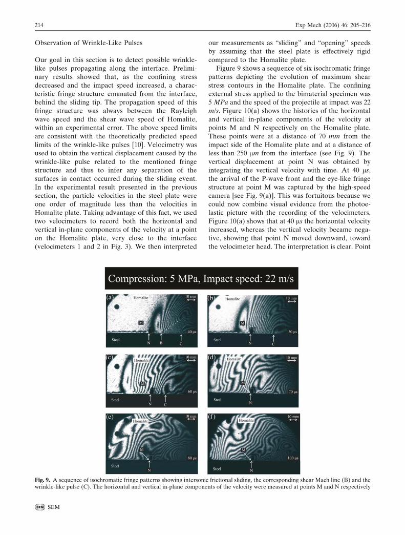
Figure 9 shows a sequence of six isochromatic fringe
patterns depicting the evolution of maximum shear
stress contours in the Homalite plate. The confining
external stress applied to the bimaterial specimen was
5 MPa and the speed of the projectile at impact was 22
m/s. Figure 10(a) shows the histories of the horizontal
and vertical in-plane components of the velocity at
points M and N respectively on the Homalite plate.
These points were at a distance of 70 mm from the
impact side of the Homalite plate and at a distance of
less than 250 2m from the interface (see Fig. 9). The
vertical displacement at point N was obtained by
integrating the vertical velocity with time. At 40 2s,
the arrival of the P-wave front and the eye-like fringe
structure at point M was captured by the high-speed
camera [see Fig. 9(a)]. This was fortuitous because we
could now combine visual evidence from the photoe-
lastic picture with the recording of the velocimeters.
Figure 10(a) shows that at 40 2s the horizontal velocity
increased, whereas the vertical velocity became nega-
tive, showing that point N moved downward, toward
the velocimeter head. The interpretation is clear. Point
Fig. 9. A sequence of isochromatic fringe patterns showing intersonic frictional sliding, the corresponding shear Mach line (B) and thewrinkle-like pulse (C). The horizontal and vertical in-plane components of the velocity were measured at points M and N respectively
214 Exp Mech (2006) 46: 205–216
SEM
M moved to the left under the influence of the
horizontal compressive stress generated by the impact.
Because of the Poisson effect, the horizontal com-
pressive stress induced a dynamic (inertial) vertical
compressive stress that forced point N to move
downward. Using the experience accumulated from
the first experiment, we estimated that sliding started
at approximately 46 2s, when the relative velocity
increased rapidly. From 40 2s to 46 2s, elastic shearing
occurred, whereas sliding initiated when the tip of the
Mach line [point B in Fig. 9(a)] crossed the velocity
measurement position M. At 50 2s, the sliding tip B
was on the left of the measurement position Fig. 9(b),
signifying that the sliding had already started. Point B
was traveling at a supershear speed of 1932 m/s =
1.55C2H. Figure 10(a) shows that at around 60 2s the
horizontal velocity reached its maximum value and the
sliding continued for the rest of the recording time
with no large variations in the sliding tip speed.
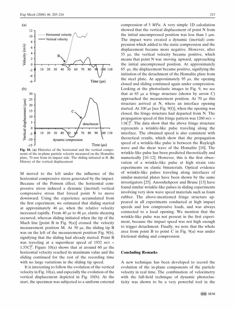
It is interesting to follow the evolution of the vertical
velocity in Fig. 10(a), and especially the evolution of the
vertical displacement depicted in Fig. 10(b). At the
start, the specimen was subjected to a uniform external
compression of 5 MPa. A very simple 1D calculation
showed that the vertical displacement of point N from
the initial uncompressed position was less than 1 2m.
The impact wave created a dynamic (inertial) com-
pression which added to the static compression and the
displacement became more negative. However, after
55 2s, the vertical velocity became positive, which
means that point N was moving upward, approaching
the initial uncompressed position. At approximately
65 2s, the displacement became positive, signifying the
initiation of the detachment of the Homalite plate from
the steel plate. At approximately 95 2s, the opening
closed and sliding continued again under compression.
Looking at the photoelastic images in Fig. 9, we see
that at 65 2s a fringe structure (shown by arrow C)
approached the measurement position. At 70 2s this
structure arrived at N, where an interface opening
started. At 100 2s [see Fig. 9(f)], when the opening was
closed, the fringe structure had departed from N. The
propagation speed of this fringe pattern was 1260 m/s =
1.0C2H. The data show that the above fringe structure
represents a wrinkle-like pulse traveling along the
interface. The obtained speed is also consistent with
theoretical results, which show that the propagation
speed of a wrinkle-like pulse is between the Rayleigh
wave and the shear wave of the Homalite [10]. The
wrinkle-like pulse has been predicted theoretically and
numerically [10–12]. However, this is the first obser-
vation of a wrinkle-like pulse at high strain rate
experiments on elastic bimaterials. Optical evidence
of wrinkle-like pulses traveling along interfaces of
similar-material plates have been shown by the same
investigators [25]. Anooshehpoor and Brune [13] have
found similar wrinkle-like pulses in sliding experiments
involving very slow wave speed materials such as foam
rubber. The above-mentioned fringe structure ap-
peared in all experiments conducted at high impact
speeds and low compressive loads, and was always
connected to a local opening. We mention that the
wrinkle-like pulse was not present in the first experi-
ment, because the impact speed was not high enough
to trigger detachment. Finally, we note that the whole
area from point B to point C in Fig. 9(a) was under
frictional sliding and compression.
Concluding Remarks
A new technique has been developed to record the
evolution of the in-plane components of the particle
velocity in real time. The combination of velocimetry
with the full-field technique of dynamic photoelas-
ticity was shown to be a very powerful tool in the
Fig. 10. (a) Histories of the horizontal and the vertical compo-nents of the in-plane particle velocity measured on the Homaliteplate, 70 mm from its impact side. The sliding initiated at B. (b)History of the vertical displacement
Exp Mech (2006) 46: 205–216 215
SEM
study of dynamic frictional sliding along incoherent
interfaces.
The experiments involved bimaterial specimens
consisting of Homalite-100 and steel plates held
together by uniform compressive stress and subjected
to impact shear loading. The following significant
effects were captured:
& The interaction between the impact wave and the
preexisting static stress field caused a relatively
broad loading wave that emanated from the
interface.
& A disturbance, traveling along the interface at a
speed close to the Rayleigh wave speed of steel,
generated a Mach line that crossed the P-wave
front and the eye-like fringe pattern. Data recorded
by the velocimeter showed that this disturbance
affected the relative velocity but did not cause
sliding.
& The velocimeter revealed that the sliding initiated
behind the eye-like fringe structure. A shear Mach
line was visible in the photoelastic images, indicat-
ing that the sliding was supershear with respect to
the shear wave speed of Homalite.
& The sliding occurred in a crack-like mode.
& A self-sustaining wrinkle-like pulse propagating
along the bimaterial interface was observed. It
caused a local detachment between the two plates
that was traveling at a speed close to the Rayleigh
wave speed of Homalite. It is expected that the
wrinkle-like pulse might play an important role in
the failure mechanism of bimaterial structures
subjected to impact shear loading.
Acknowledgments The authors gratefully acknowledge thesupport of the Office of Naval Research through grant N00014-03-1-0435 (Dr. Y.D.S. Rajapakse, Program Manager). Theauthors would also like to thank BPolytec’’, USA, (M. Pinedaand E. Lawrence), for the use of the second velocimeter.
References
1. Freund LB (1990) Dynamic fracture mechanics. Cambridge,UK.
2. Broberg KB (1999) Cracks and fracture. Academic Press,London.
3. Rosakis AJ (2002) Intersonic shear cracks and fault ruptures.Adv Phys 51(4):1189–1257.
4. Tippur HV, Rosakis AJ (1991) Quasi-static and dynamiccrack growth along bimaterial interfaces: a note on crack-tip
field measurements using coherent gradient sensing. ExpMech 31:243–251.
5. Liu C, Lambros J, Rosakis AJ (1993) Highly transientelastodynamic crack growth in a bimaterial interface: higherorder asymptotic analysis and optical experiments. J MechPhys Solids 41(12):1857–1954.
6. Lambros J, Rosakis AJ (1995) Shear dominated transonicinterfacial crack growth in a bimaterial-I. Experimentalobservations. J Mech Phys Solids 43(2):169–188.
7. Singh RP, Shukla A (1996) Subsonic and transonic crackgrowth along a bimaterial interface. J Appl Mech 63:919–924.
8. Rosakis AJ, Samudrala O, Singh RP, Shukla A (1998)Intersonic crack propagation in bimaterial systems. J MechPhys Solids 46(10):1789–1813.
9. Kavaturu M, Shukla A, Rosakis AJ (1998) Intersonic crackpropagation and interfaces: experimental observations andanalysis. Exp Mech 38(3):218–225.
10. Comninou M, Dundurs J (1977) Elastic interface wavesinvolving separation. J Appl Mech ASME 44:222–226.
11. Weertman J (1980) Unstable slippage across a fault thatseparates elastic media of different elastic constants. JGeophys Res 85:1455–1461.
12. Andrews DJ, Ben-Zion Y (1997) Wrinkle-like slip pulse on afault between different materials. J Geophys Res 102:553–571.
13. Anooshehpoor A, Brune JN (1999) Wrinkle-like Weert-man pulse at the interface between two blocks of foam rubberwith different velocities. Geophys Res Lett 23:2025–2028.
14. Abou-Sayed AS, Clifton RJ, Hermann L (1976) TheOblique-plate impact experiment. Exp Mech 16:127–132.
15. Kim K-S, Clifton RJ, Kumar P (1977) A combined normal-and transverse-displacement interferometer with an applica-tion to impact of y-cut quartz. J Appl Phys 48(10):4132–4139.
16. Sharpe WN (1971) Interferometric surface strain measure-ment. Int J Nondestr Test 3:59–76.
17. Sharpe WN, Payne TS, Smith MK (1978) Biaxial laser-baseddisplacement transducer. Rev Sci Instrum 49(6): 741–745.
18. Lu J, Suresh S, Ravichandran G (1998) Dynamic indentationfor determining the strain rate sensitivity of metals. J MechPhys Solids 51(11–12):1923–1938.
19. Achenbach JD, Epstein HI (1967) Dynamic interaction of alayer and a half-space. J Eng Mech 5:27–42.
20. Ranjith K, Rice JR (2001) Slip dynamics at an interfacebetween dissimilar materials. J Mech Phys Solids 49:341–361.
21. Rice JR, Lapusta N, Ranjith K (2001) Rate and statedependent friction and the stability of sliding betweenelastically deformable solids. J Mech Phys Solids 49:1865–1898.
22. Samudrala O, Rosakis AJ (2003) Effect of loading andgeometry on the subsonic/intersonic transition of bimaterialinterface crack. Eng Fract Mech 70:309–337.
23. Samudrala O, Huang Y, Rosakis AJ (2002) Subsonic andintersonic mode II crack propagation with a rate-dependentcohesive zone. J Mech Phys Solids 50:1231–1268.
24. Coker D, Rosakis AJ, Needleman A (2003) Dynamic crackgrowth along a polymer composite-homalite interface. JMech Phys Solids 51:425–460.
25. Lykotrafitis G, Rosakis AJ (2006) Sliding along frictionallyheld incoherent interfaces in homogeneous systems underdynamic shear loading. Int J Fract, accepted.
216 Exp Mech (2006) 46: 205–216
SEM