Embed Size (px)
Citation preview
August 30, 2011
TO: PARTIES INTERESTED IN HELICAL PILE FOUNDATION SYSTEMS AND
DEVICES SUBJECT: Proposed Revisions to the Acceptance Criteria for Helical Foundation Systems
and Devices, Subject AC358-1011-R1 (YM/DZ)
Hearing Information: Tuesday, October 11, 2011 10:00 am DoubleTree Hotel 808 South 20th Street Birmingham, Alabama 35205 (800) 222-8733
Dear Colleague:
You are invited to comment on proposed revisions to AC358, which will be discussed at the Evaluation Committee hearing noted above. The criteria is being revised to reference the 2012 and 2009 International Building Code® (IBC). In addition, we received a letter with proposed revisions from the Helical Pile Ad-Hoc Committee (copy attached). We intended to keep the current version of AC358 for reports under the 2006 IBC, and the following revisions to AC358 are being proposed:
1. Update criteria to the 2012 and 2009 IBC and update referenced standards to be consistent with the 2012/2009 IBC.
2. Include a condition in Section 3.6 clarifying how the lateral load capacity should be determined.
3. Include a statement in Section 3.7.1 indicating that the allowable stresses should not exceed both 0.6Fy and 0.5Fu.
4. Include a statement in Section 3.7.1.2 clarifying when it is necessary to use Equation 4.
5. Include a statement in Section 3.7.2 indicating that the tested capacity must exceed the calculated capacity.
6. Include a statement in Section 3.9 to clarify how to determine the thickness of the zinc-coated steel.
AC358-1011-R1
2
7. Revise Section 3.9 to state conditions where zinc-coated steel helical pile components may be in contact with bare steel helical pile components, along with provision for determining the sacrificial thickness.
8. Include a provision in Section 3.11 to consider the pile splice provisions found in Section 1810.3.6 of the IBC.
9. Include a provision in Section 3.11.2.3 to explain how the coupling rigidity is to be determined.
10. Add Sections 3.11.3.2, 3.12.4, 4.2.2.1.2, 4.2.2.1.3, 4.2.2.2.1, 4.2.2.2.2, 4.2.2.2.3 to clarify the requirements for torsional tests of shafts including helical plates.
11. Include wording in Sections 3.13.1, 3.13.3 and 3.13.4 to indicate that geotechnical investigation must be conducted in accordance with the IBC.
12. Include wording in Section 4.1.1.1 to indicate that the test shaft specimens must have a standard manufactured coupling.
13. Include wording in Section 4.2.4.2 to indicate that the net coupling deflection must be determined by conducting side-by-side comparison tests, with and without couplers.
14. Revise the equation shown in Figure 13 to “1/2(Rb+Rs) to be consistent with Section 4.3.1.
15. Revise Section 4.4.1.1 to replace “installation device” with “installation torque indicator.”
16. Revise Section 4.4.1.1 to identify the testing procedure used in tension load tests.
17. Revise Section 4.4.2.1 to identify the testing procedure used in lateral load tests.
18. Include a statement in Section 6.1 indicating that the use of helical piles in Seismic Design Categories D, E, and F or in Site Class E or F is outside the scope of the report.
19. Revise Section 6.7 to clarify the spacing requirements of helical piles when determining group effects.
20. Include a condition of use statement in Section 6.7 to indicate that a registered design professional will need to address the applicable provisions in Sections 1810.3 of the 2012 and 2009 IBC.
21. Revise Section 6.9 to include a statement that the pile must be installed in accordance with Section 1810.4.11 of the IBC.
22. Revise Section 6.10 by deleting the option allowing periodic inspections. The reason for this change is that 2012 IBC Section 1705.9 and 2009 IBC Section 1704.10 require continuous special inspection.
AC358-1011-R1
3
23. Revise “helical foundation” to “helical pile” to be consistent with the 2012 and 2009 IBC.
We are particularly interested in your input on the following items which are contained in the Ad-Hoc Committee letter:
1. Include a definition for the term of “final installation torque.” According to the letter, the final installation torque is a mathematical function of the torsional resistance readings taken during pile installation. This function may vary depending on the intended loading conditions and the helical pile configuration. Our understanding has been that the final installation torque was the last torque reading reported during installation. If there are other methods that are being used by manufacturers and installers, the test reports need to identify them so these can be incorporated into the evaluation report. We would like to know what is the mathematical function used to establish the final installation torque and how the “final installation torque” should be defined.
2. Revise Section 3.7.3 to establish allowable capacity when yield strength is not well defined. We believe that the capacity at yield strength needs to be determined. This is because the safety factor should be increased by using the ultimate strength criteria alone in comparison to allowable capacity based on both ultimate and yield strength criteria. Also, allowable capacity based on yield strength is required in order to compare special analysis with test data for yield related limit state.
3. Delete the following sentence from Section 3.9: “All helical pile components shall be galvanically isolated from concrete reinforcing steel, building structural steel, or any other metal building components.” The ICC-ES staff recommends retaining the statement, since the helical pile component should not negatively affect the corrosion protection of other steel systems.
4. Include new definition for Type A bracket in Section 3.10.1. We believe that the capacity of the Type A bracket without a bottom bearing plate should only be established through special analysis in accordance with Section 3.7.2. The reason for this is the eccentricity created by the installation of the bracket to the concrete and the stresses it presents on the anchorage. If recognition of a Type A bracket without a bottom bearing plate is sought, revisions to include a method to analyze this type of bracket will need to be included in Section 3.10.1.
5. Delete Sections 3.10.1.1.1, 3.10.1.1.2, and 3.10.1.1.3. The ICC-ES staff recommends retaining these sections. We believe that removing these sections does not provide sufficient guidance on how to evaluate the Type A bracket capacity and its connection to the shaft and foundation.
6. Revisions to Axial Verification Tests, Section 3.13.1. We agree that this section needs to be revised to clarify its intent. Our interpretation of this section is that it serves two purposes. First, it could be used to establish the pile axial capacity based on a specific tested pile assembly at a specific soil site. In other words you get what you
AC358-1011-R1
4
test. The second purpose of this section is to ensure that the pile when installed at the maximum torque will not be damaged. Since Section 1810.3.3.1.9 of the 2009 IBC requires that the ultimate axial capacity be based on well-documented torque correlations, we believe that the “you get what you test” approach is no longer acceptable. The intent of Section 3.13.1 will be only to verify that the helical pile will be able to achieve an ultimate capacity of two times its allowable load based on torque correlation factor without any damage to the pile.
7. Revision to Section 3.13.2.1 to allow lower Kt values for conforming systems. Section 3.13.2.1 allows the use of the Kt values based on successful testing in accordance with Table 2. However, if one fails to meet the minimum torque correlation values, it will fall under a nonconforming system which requires additional testing. The Ad-Hoc Committee letter is requesting to allow the use of a lower Kt value based on testing in accordance with Table 2. This approach seems to significantly drift from the current requirements in Section 3.13.2.1. We question how this lower Kt value will be established from the submitted test data, since the required sample population for conforming and noncoforming systems is based on historical evidence previously submitted in the development of AC358.
8. Revision to determine Kt values of shaft sizes not listed in Section 3.13.2.1. We are unclear as to the intent of this revision. Table 3 allows only four different type of shafts for conforming systems. Section 3.13.2.2 provides guidelines to establish torque correlation of nonconforming systems. Therefore it seems that this revision is not needed.
9. Revision to include an iterative approach to establish Kt value for nonconforming system in Section 3.13.2.2. The iterative approach described does not include the torque correlation parameter. We would like to know how the Kt value can be established when the torque correlation value is not part of the iterative approach. We would like to know why the condition of acceptance, that the Kt value shall be considered valid if 94 percent of data have a Qf/Qa ratio greater than 0.5, is not included in the proposed revision.
10. We previously raised a question on the effectiveness of conducting compression load tests using the quick load method described in ASTM D 1143 (Section 4.4.1.1) for installation in clay soils. The response provided in the Helical Pile Ad-Hoc committee letter was that this issue is a serviceability concern and that the consolidation of the soil leads to a higher capacity. We would like to know how settlement, as required in Section 1808.2 and 1810.2.3 of the IBC, is addressed in clay soils when the pile is subjected to long-term loading, since only quick load tests are being required.
11. Revise Section 6.9 by deleting the requirement that in tension applications the uppermost helix shall be 12D and replacing this by a statement indicating that a registered design professional shall establish the minimum depth. Section 4.4.1.1 states that tensile load tests must be installed at a depth of 12D, where D is the diameter of the largest helix. We believe that the embedment depth of the helical pile
AC358-1011-R1
5
has an effect on its tensile capacity. The proposed revision suggests that the minimum depth of the helical pile resisting tensile forces shall be determined by a registered design professional. It is not clear how this can be accomplished, since the axial tensile capacity is based on full-scale load tests.
12. Regarding item 1 of 2009 IBC Section 1810.3.3.1.9. Item 1 of 2009 IBC Section 1810.3.3.1.9 states that the load shall be determined by taking the sum of the areas of the helical bearing plates and multiplying times the ultimate bearing capacity of the soil. Although we agree that this limit state must be verified by the registered design professional based on specific site conditions, we have the following questions regarding this condition:
a. How does the spacing of the helical plates (for multiple plate applications) affect the bearing capacity in axial compression and tension load applications?
b. If the plates are closely spaced, should the sum of the areas of the plates be taken?
c. What is the closest spacing permitted to allow the soil bearing capacity to interact with the each plate without affecting plates located above or below?
13. Regarding the provisions for pile splices in 2009 IBC Section 1810.3.6 and Section 3.11 of AC358. This section of the code states that the bending strength of pile splices shall not be less than 50 percent of the weaker pile section bending strength, and that an eccentricity of 3 inches shall be assumed when a splice occurs in the upper 10 feet of the embedded portion of the pile. According to the proponent’s response, they feel that the provisions found in this section of the code are not applicable to helical piles, but only to driven piles. Although the code in this section does not differentiate between driven and helical piles, we believe that the provisions of this section need to be considered in the helical pile design unless the code is revised to specifically limit this splice provision to driven piles.
14. Regarding side load bracket connection to the pile cap, grade beam, or concrete footing for helical piles that support structures to Seismic Design Category C. The response provided by the Ad-Hoc Committee is not considered adequate for the following reasons:
a. It is true that ACI 318 is not intended for concrete piles, piers and caissons, except that Section 21.12.4, as indicated in ACI 318 Section 1.1.6. Commentary to ACI 318 Section 1.1.6, refers to ACI 543, ACI 336 and PCI Recommended Practices for Design, Manufacture, and Installation of Prestressed Concrete Piling (PCI piling document). As indicated in our previous e-mail to the Ad-Hoc Committee, dated May 25, 2011, IBC Section 1810.3.11.1 (2012 and 2009 IBC) requires that the connection of piles to pile caps be made with mechanical means, such as embedded reinforcements, dowel-anchors or deformed bars. The intent of this provision is to ensure a ductile connection between pile and pile cap. This intent is clarified in the referenced documents in Section 1.1.6 of ACI 318-08. For example, the PCI piling
AC358-1011-R1
6
document, Section 2.5.2, states, “Prestressed concrete piling, like all other piles, will undergo imposed displacements and curvature under strong seismic action. . . . Curvature may be particularly severe at abrupt change in soil stiffness and at connections to the pile cap.” Item (e) of Section 2.5.2 in this PCI piling document prescribes lateral transverse reinforcement in the region where pile reinforcement extends into pile caps in order to achieve this ductile connection requirement. As another illustration, Section 2.3.6 of ACI 543 prescribes seismic requirements for piles, and states, “In areas of seismic risk, design piles or other members on the basis of strength alone is not adequate. These members must also possess adequate ductility, and more importantly, ductility under fully reversed moment condition. . . . Curvature or rotational ductility is important to seismic response. . . . Areas of concentrated rotation can occur where pile is connected to the pile cap . . .” Since connection of helical piles to pile caps is not specifically addressed in the IBC, it is important that AC358 address this issue in order to ensure the expected seismic performance of helical pile foundation systems.
b. As explained in item a, above, the references identified in the Commentary of Section 1.1.6 of ACI 318 are intended for pile/pier design (structural and geotechnical), and the connections of piles/piers to pile caps are addressed by the building code (IBC) and its referenced standard (such as ACI 318). As explained in our e-mail to the Ad-Hoc Committee, dated May 25, 2011, item 1b, “based on the quoted ACI 318 and PCI paragraphs, it appears that connection details that solely rely on friction caused by gravity loads are not allowed due to structural integrity concern regardless of the SDC category for the building structures, and mechanical connection is always required.”
c. We would like to know how the provisions presented in Comment 14a and 14b can be incorporated in AC358.
15. Regarding the use of a coefficient of friction of 0.4 between side load bracket and concrete footing. The response provided by the Ad-Hoc Committee is not adequate for the following reasons:
a. The friction reduction due to wet use condition is not addressed.
b. The coefficients of friction described in ACI 318-08 Section 11.6.4.3 were adopted due to the assumed model for shear resistance as described in the Commentary Section R11.6.4.3 of ACI 318, and should not be used without modification.
c. The response by the Ad-Hoc committee indicated that CTL/Thompson has performed over 100 side load bracket tests. In order to provide justification by testing/analysis as indicated by the response, the test data analysis considering different bracket configurations and statistical evaluation should be provided, as this can be used to substantiate the chosen coefficient of friction of 0.4.
AC358-1011-R1
7
If revisions are approved by the Evaluation Committee, the ICC-ES technical staff will not recommend any mandatory compliance date, as compliance with the revisions to this criteria will be voluntary (i.e., implemented as report holders update their reports to the 2009 and 2012 codes). You are invited to submit written comments on this or any other agenda item, or to attend the Evaluation Committee hearing and present your views in person. If you wish to contribute to the discussion, please note the following: 1. Regarding written comments:
a. You should submit these to the Los Angeles business/regional office.
b. Comments received by September 20, 2011, will be forwarded to the committee
before the meeting, and also will be posted on the ICC-ES web site shortly after the deadline for submission.
c. ICC-ES will also post to the web site, on October 7, 2011, comments that miss the
above deadline but are received up to ten days before the meeting. On this same date, memos by the ICC-ES staff, responding to public comments, will be posted to the web site.
d. If you miss the deadline for materials to be forwarded to the committee, we can still have your comments available at the hearing if you provide 35 copies, collated, stapled, and three-hole-punched, either at the meeting itself or to the Los Angeles business/regional office by October 7, 2011.
e. Proposed criteria, written public comments, and responses by ICC-ES staff will be available at the meeting on a limited number of CDs for uploading to computers. Also, while ICC-ES will not provide any printed copies, the hotel business center will have hard copies for photocopying.
2. Regarding verbal comments:
a. If you plan to speak for more than fifteen minutes, or if you have any special needs related to a presentation, please notify ICC-ES staff as far as possible in advance. We will provide a computer, projector, and screen to anyone wishing to make a visual presentation, which in most cases should be in PowerPoint format.
b. Presentations, and any other visual aids for viewing at the meeting (transparencies, slides, videos, charts, etc.), must be provided in advance to ICC-ES, in a medium that can be retained with other records of the meeting.
3. Keep in mind that all materials submitted for committee consideration are part of the
public record, and will not be treated as confidential.
AC358-1011-R1
8
4. Please do not try to communicate with any committee members before the meeting about any items on the agenda.
We appreciate your interest in the work of the Evaluation Committee. If you have any questions, please contact me at (800) 423-6587, extension 3275, or David Zhao, S.E., Senior Staff Engineer, at extension 3275. You may also reach us by e-mail at [email protected].
Yours very truly,
Yamil Moya, P.E. Staff Engineer
YM/md Enclosure cc: Evaluation Committee
Page 1 of 12
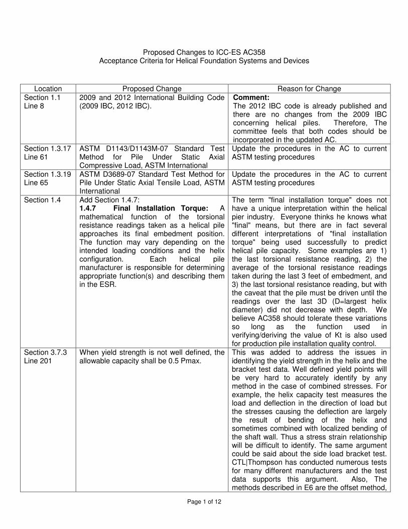
Proposed Changes to ICC-ES AC358 Acceptance Criteria for Helical Foundation Systems and Devices
Location Proposed Change Reason for Change Section 1.1 Line 8
2009 and 2012 International Building Code (2009 IBC, 2012 IBC).
Comment: The 2012 IBC code is already published and there are no changes from the 2009 IBC concerning helical piles. Therefore, The committee feels that both codes should be incorporated in the updated AC.
Section 1.3.17 Line 61
ASTM D1143/D1143M-07 Standard Test Method for Pile Under Static Axial Compressive Load, ASTM International
Update the procedures in the AC to current ASTM testing procedures
Section 1.3.19 Line 65
ASTM D3689-07 Standard Test Method for Pile Under Static Axial Tensile Load, ASTM International
Update the procedures in the AC to current ASTM testing procedures
Section 1.4
Add Section 1.4.7: 1.4.7 Final Installation Torque: A mathematical function of the torsional resistance readings taken as a helical pile approaches its final embedment position. The function may vary depending on the intended loading conditions and the helix configuration. Each helical pile manufacturer is responsible for determining appropriate function(s) and describing them in the ESR.
The term "final installation torque" does not have a unique interpretation within the helical pier industry. Everyone thinks he knows what "final" means, but there are in fact several different interpretations of "final installation torque" being used successfully to predict helical pile capacity. Some examples are 1) the last torsional resistance reading, 2) the average of the torsional resistance readings taken during the last 3 feet of embedment, and 3) the last torsional resistance reading, but with the caveat that the pile must be driven until the readings over the last 3D (D=largest helix diameter) did not decrease with depth. We believe AC358 should tolerate these variations so long as the function used in verifying/deriving the value of Kt is also used for production pile installation quality control.
Section 3.7.3 Line 201
When yield strength is not well defined, the allowable capacity shall be 0.5 Pmax.
This was added to address the issues in identifying the yield strength in the helix and the bracket test data. Well defined yield points will be very hard to accurately identify by any method in the case of combined stresses. For example, the helix capacity test measures the load and deflection in the direction of load but the stresses causing the deflection are largely the result of bending of the helix and sometimes combined with localized bending of the shaft wall. Thus a stress strain relationship will be difficult to identify. The same argument could be said about the side load bracket test. CTL|Thompson has conducted numerous tests for many different manufacturers and the test data supports this argument. Also, The methods described in E6 are the offset method,
Page 2 of 12
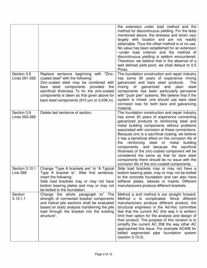
the extension under load method and the method for discontinuous yielding. For the tests mentioned above, the stresses and strain vary largely with location and are not readily obtainable. Thus the offset method is of no use. No value has been established for an extension –under load criterion and the method of discontinuous yielding is seldom encountered. Therefore, we believe that in the absence of a well defined yield point, we shall default to 0.5 Pmax.
Section 3.9 Lines 261-262
Replace sentence beginning with "Zinc-coated steel" with the following: Zinc-coated steel may be combined with bare steel components provided the sacrificial thickness Ts for the zinc-coated components is taken as that given above for bare steel components (915 µm or 0.036 in).
The foundation construction and repair industry has some 30 years of experience mixing galvanized and bare steel products. The mixing of galvanized and plain steel components has been particularly pervasive with “push pier” systems. We believe that if the system is mixed, one should use bare steel corrosion loss for both bare and galvanizing material.
Section 3.9 Lines 263-265
Delete last sentence of section. The foundation construction and repair industry has some 30 years of experience connecting galvanized products to reinforcing steel and metal building components without problems associated with corrosion at these connections. Because zinc is a sacrificial coating, we believe it has a beneficial effect on the corrosion life of the reinforcing steel or metal building components, and because the sacrificial thickness of the zinc-coated component will be considered the same as that for bare steel components there should be no issue with the corrosion life of the zinc-coated components.
Section 3.10.1 Line 289
Change “Type A brackets are” to “A Typical Type A bracket is”. After first sentence, insert the following: Side load brackets may or may not have bottom bearing plates and may or may not be bolted to the foundation.
Side load brackets may or may not have a bottom bearing plate, may or may not be bolted to the concrete foundation and can also have stiffener plates, sleeves or inserts. Different manufacturers produce different brackets.
Section 3.10.1.1
Change the whole paragraph to” The strength of connected bracket components and helical pile sections shall be evaluated based on static analysis transferring the pile load through the bracket into the existing structure”.
Method a and method b are straight forward. Method c is complicated. Since different manufacturers produce different product, the structural engineers in the Ad-Hoc committee feel that the current AC (the way it is written) limit their option for the analysis and design of their product. The purpose of this revision is to simplify the current AC 358 the way other AC approached this issue. For example AC406 for belled segmented pipe foundation system (section 3.10.2).
Page 3 of 12
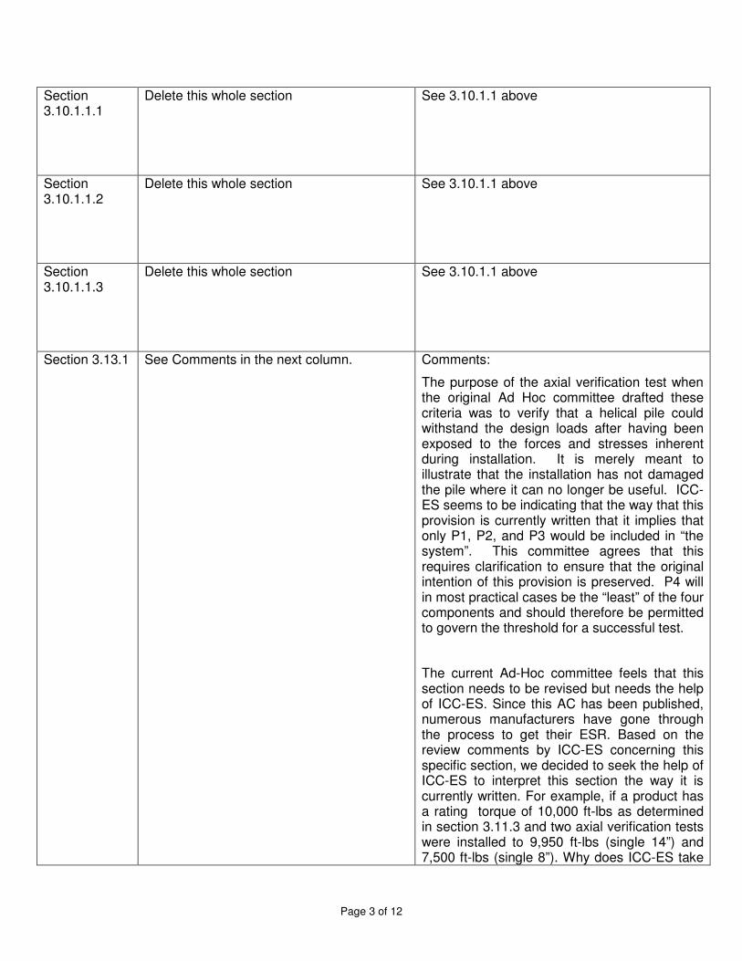
Section 3.10.1.1.1
Delete this whole section See 3.10.1.1 above
Section 3.10.1.1.2
Delete this whole section See 3.10.1.1 above
Section 3.10.1.1.3
Delete this whole section See 3.10.1.1 above
Section 3.13.1
See Comments in the next column. Comments:
The purpose of the axial verification test when the original Ad Hoc committee drafted these criteria was to verify that a helical pile could withstand the design loads after having been exposed to the forces and stresses inherent during installation. It is merely meant to illustrate that the installation has not damaged the pile where it can no longer be useful. ICC-ES seems to be indicating that the way that this provision is currently written that it implies that only P1, P2, and P3 would be included in “the system”. This committee agrees that this requires clarification to ensure that the original intention of this provision is preserved. P4 will in most practical cases be the “least” of the four components and should therefore be permitted to govern the threshold for a successful test.
The current Ad-Hoc committee feels that this section needs to be revised but needs the help of ICC-ES. Since this AC has been published, numerous manufacturers have gone through the process to get their ESR. Based on the review comments by ICC-ES concerning this specific section, we decided to seek the help of ICC-ES to interpret this section the way it is currently written. For example, if a product has a rating torque of 10,000 ft-lbs as determined in section 3.11.3 and two axial verification tests were installed to 9,950 ft-lbs (single 14”) and 7,500 ft-lbs (single 8”). Why does ICC-ES take
Page 4 of 12
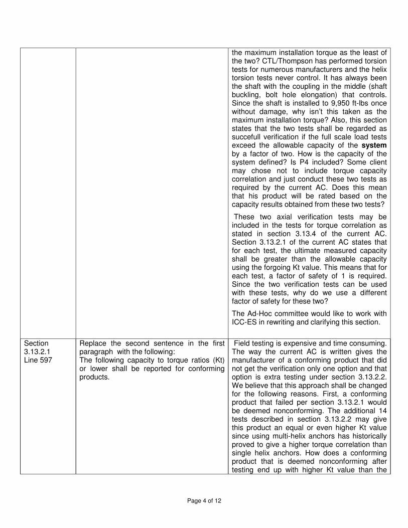
the maximum installation torque as the least of the two? CTL/Thompson has performed torsion tests for numerous manufacturers and the helix torsion tests never control. It has always been the shaft with the coupling in the middle (shaft buckling, bolt hole elongation) that controls. Since the shaft is installed to 9,950 ft-lbs once without damage, why isn’t this taken as the maximum installation torque? Also, this section states that the two tests shall be regarded as succefull verification if the full scale load tests exceed the allowable capacity of the system by a factor of two. How is the capacity of the system defined? Is P4 included? Some client may chose not to include torque capacity correlation and just conduct these two tests as required by the current AC. Does this mean that his product will be rated based on the capacity results obtained from these two tests?
These two axial verification tests may be included in the tests for torque correlation as stated in section 3.13.4 of the current AC. Section 3.13.2.1 of the current AC states that for each test, the ultimate measured capacity shall be greater than the allowable capacity using the forgoing Kt value. This means that for each test, a factor of safety of 1 is required. Since the two verification tests can be used with these tests, why do we use a different factor of safety for these two?
The Ad-Hoc committee would like to work with ICC-ES in rewriting and clarifying this section.
Section 3.13.2.1 Line 597
Replace the second sentence in the first paragraph with the following: The following capacity to torque ratios (Kt) or lower shall be reported for conforming products.
Field testing is expensive and time consuming. The way the current AC is written gives the manufacturer of a conforming product that did not get the verification only one option and that option is extra testing under section 3.13.2.2. We believe that this approach shall be changed for the following reasons. First, a conforming product that failed per section 3.13.2.1 would be deemed nonconforming. The additional 14 tests described in section 3.13.2.2 may give this product an equal or even higher Kt value since using multi-helix anchors has historically proved to give a higher torque correlation than single helix anchors. How does a conforming product that is deemed nonconforming after testing end up with higher Kt value than the
Page 5 of 12
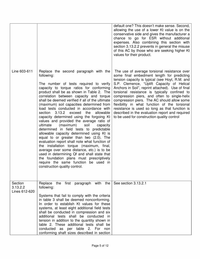
Line 603-611
Replace the second paragraph with the following: The number of tests required to verify capacity to torque ratios for conforming product shall be as shown in Table 2. The correlation between capacity and torque shall be deemed verified if all of the ultimate (maximum) soil capacities determined from load tests conducted in accordance with section 3.13.2 exceed the allowable capacity determined using the forgoing Kt values and provided the average ratio of ultimate (maximum) soil capacity determined in field tests to predictable allowable capacity determined using Kt is equal to or greater than two (2.0). The evaluation report shall note what function of the installation torque (maximum, final, average over some distance, etc.) is to be used in determining Qf and shall state that the foundation plans must prescriptively require the same function be used in construction quality control.
default one? This doesn’t make sense. Second, allowing the use of a lower Kt value is on the conservative side and gives the manufacturer a chance to go for ESR without additional expenses. Also combining this section with section 3.13.2.2 prevents in general the misuse of this AC by those who are seeking higher Kt values for their product. The use of average torsional resistance over some final embedment length for predicting tension capacity is typical (see Hoyt, R.M. and S.P. Clemence, “Uplift Capacity of Helical Anchors in Soil”, reprint attached). Use of final torsional resistance is typically confined to compression piers, and often to single-helix compression piers. The AC should allow some flexibility in what function of the torsional resistance is used so long as that function is described in the evaluation report and required to be used for construction quality control
Section 3.13.2.2 Lines 612-620
Replace the first paragraph with the following: Systems that fail to comply with the criteria in table 3 shall be deemed nonconforming. In order to establish Kt values for these systems, at least eight additional field tests shall be conducted in compression and six additional tests shall be conducted in tension in addition to the quantity shown in table 2. These additional tests shall be conducted as per table 2. For non conforming shaft sizes described in section
See section 3.13.2.1
Page 6 of 12
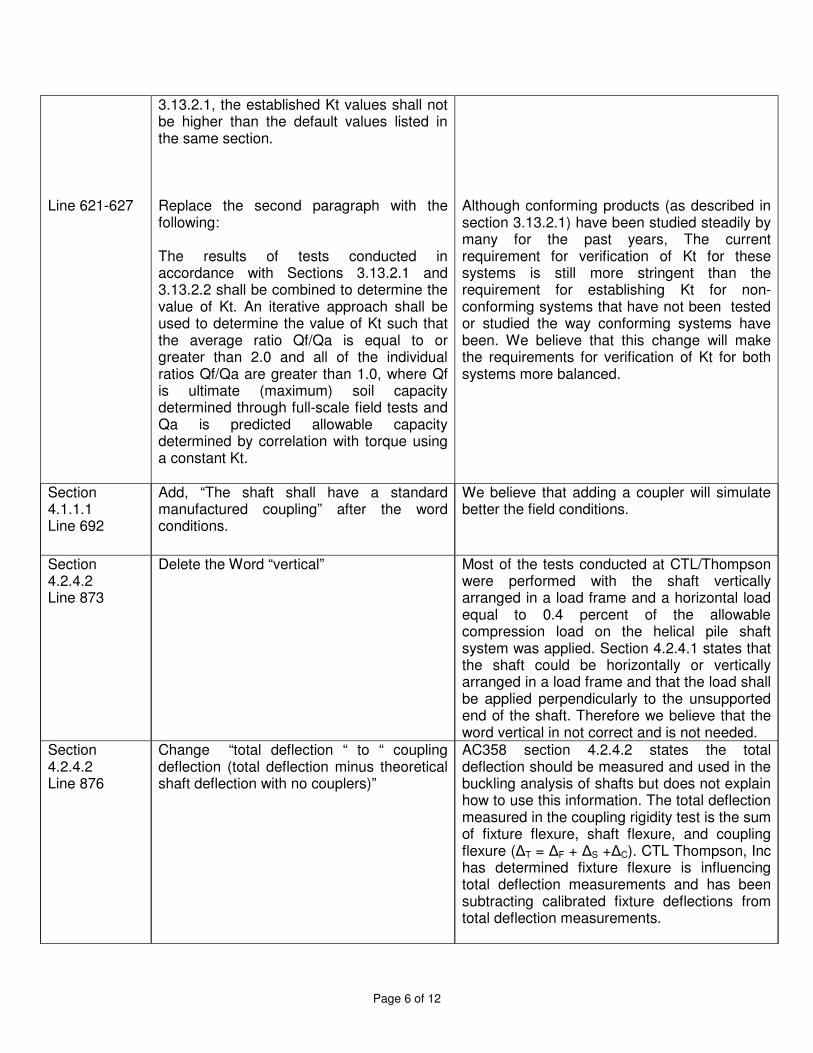
Line 621-627
3.13.2.1, the established Kt values shall not be higher than the default values listed in the same section. Replace the second paragraph with the following: The results of tests conducted in accordance with Sections 3.13.2.1 and 3.13.2.2 shall be combined to determine the value of Kt. An iterative approach shall be used to determine the value of Kt such that the average ratio Qf/Qa is equal to or greater than 2.0 and all of the individual ratios Qf/Qa are greater than 1.0, where Qf is ultimate (maximum) soil capacity determined through full-scale field tests and Qa is predicted allowable capacity determined by correlation with torque using a constant Kt.
Although conforming products (as described in section 3.13.2.1) have been studied steadily by many for the past years, The current requirement for verification of Kt for these systems is still more stringent than the requirement for establishing Kt for non-conforming systems that have not been tested or studied the way conforming systems have been. We believe that this change will make the requirements for verification of Kt for both systems more balanced.
Section 4.1.1.1 Line 692
Add, “The shaft shall have a standard manufactured coupling” after the word conditions.
We believe that adding a coupler will simulate better the field conditions.
Section 4.2.4.2 Line 873
Delete the Word “vertical” Most of the tests conducted at CTL/Thompson were performed with the shaft vertically arranged in a load frame and a horizontal load equal to 0.4 percent of the allowable compression load on the helical pile shaft system was applied. Section 4.2.4.1 states that the shaft could be horizontally or vertically arranged in a load frame and that the load shall be applied perpendicularly to the unsupported end of the shaft. Therefore we believe that the word vertical in not correct and is not needed.
Section 4.2.4.2 Line 876
Change “total deflection “ to “ coupling deflection (total deflection minus theoretical shaft deflection with no couplers)”
AC358 section 4.2.4.2 states the total deflection should be measured and used in the buckling analysis of shafts but does not explain how to use this information. The total deflection measured in the coupling rigidity test is the sum of fixture flexure, shaft flexure, and coupling flexure (�T = �F + �S +�C). CTL Thompson, Inc has determined fixture flexure is influencing total deflection measurements and has been subtracting calibrated fixture deflections from total deflection measurements.
Page 7 of 12
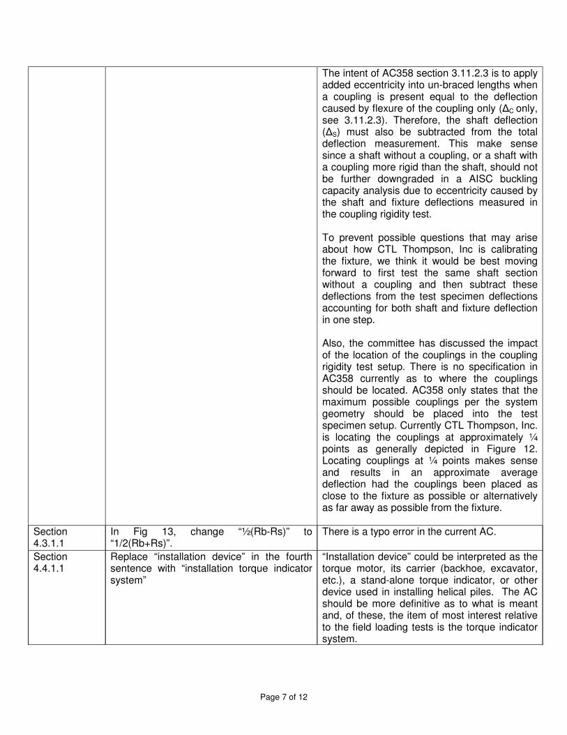
The intent of AC358 section 3.11.2.3 is to apply added eccentricity into un-braced lengths when a coupling is present equal to the deflection caused by flexure of the coupling only (�C only, see 3.11.2.3). Therefore, the shaft deflection (�S) must also be subtracted from the total deflection measurement. This make sense since a shaft without a coupling, or a shaft with a coupling more rigid than the shaft, should not be further downgraded in a AISC buckling capacity analysis due to eccentricity caused by the shaft and fixture deflections measured in the coupling rigidity test. To prevent possible questions that may arise about how CTL Thompson, Inc is calibrating the fixture, we think it would be best moving forward to first test the same shaft section without a coupling and then subtract these deflections from the test specimen deflections accounting for both shaft and fixture deflection in one step. Also, the committee has discussed the impact of the location of the couplings in the coupling rigidity test setup. There is no specification in AC358 currently as to where the couplings should be located. AC358 only states that the maximum possible couplings per the system geometry should be placed into the test specimen setup. Currently CTL Thompson, Inc. is locating the couplings at approximately ¼ points as generally depicted in Figure 12. Locating couplings at ¼ points makes sense and results in an approximate average deflection had the couplings been placed as close to the fixture as possible or alternatively as far away as possible from the fixture.
Section 4.3.1.1
In Fig 13, change “½(Rb-Rs)” to “1/2(Rb+Rs)”.
There is a typo error in the current AC.
Section 4.4.1.1
Replace “installation device” in the fourth sentence with “installation torque indicator system”
“Installation device” could be interpreted as the torque motor, its carrier (backhoe, excavator, etc.), a stand-alone torque indicator, or other device used in installing helical piles. The AC should be more definitive as to what is meant and, of these, the item of most interest relative to the field loading tests is the torque indicator system.
Page 8 of 12
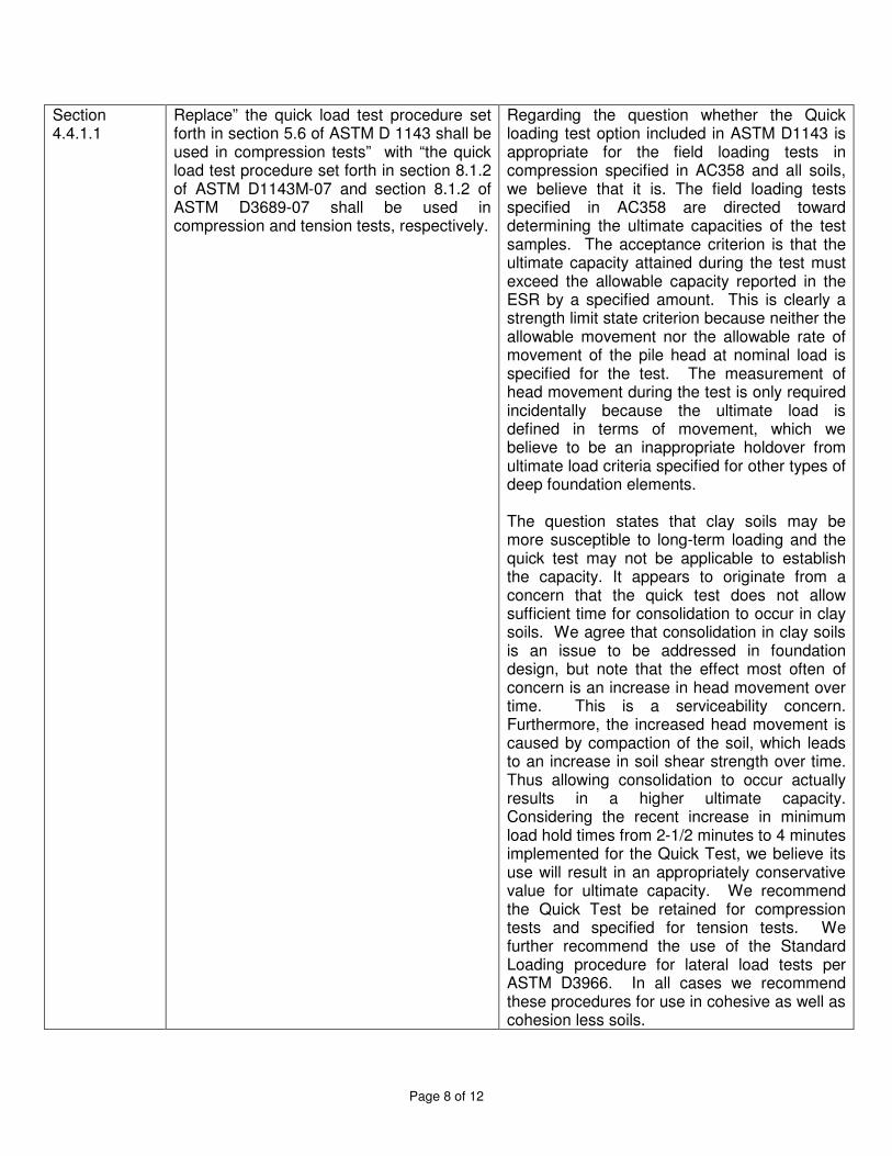
Section 4.4.1.1
Replace” the quick load test procedure set forth in section 5.6 of ASTM D 1143 shall be used in compression tests” with “the quick load test procedure set forth in section 8.1.2 of ASTM D1143M-07 and section 8.1.2 of ASTM D3689-07 shall be used in compression and tension tests, respectively.
Regarding the question whether the Quick loading test option included in ASTM D1143 is appropriate for the field loading tests in compression specified in AC358 and all soils, we believe that it is. The field loading tests specified in AC358 are directed toward determining the ultimate capacities of the test samples. The acceptance criterion is that the ultimate capacity attained during the test must exceed the allowable capacity reported in the ESR by a specified amount. This is clearly a strength limit state criterion because neither the allowable movement nor the allowable rate of movement of the pile head at nominal load is specified for the test. The measurement of head movement during the test is only required incidentally because the ultimate load is defined in terms of movement, which we believe to be an inappropriate holdover from ultimate load criteria specified for other types of deep foundation elements. The question states that clay soils may be more susceptible to long-term loading and the quick test may not be applicable to establish the capacity. It appears to originate from a concern that the quick test does not allow sufficient time for consolidation to occur in clay soils. We agree that consolidation in clay soils is an issue to be addressed in foundation design, but note that the effect most often of concern is an increase in head movement over time. This is a serviceability concern. Furthermore, the increased head movement is caused by compaction of the soil, which leads to an increase in soil shear strength over time. Thus allowing consolidation to occur actually results in a higher ultimate capacity. Considering the recent increase in minimum load hold times from 2-1/2 minutes to 4 minutes implemented for the Quick Test, we believe its use will result in an appropriately conservative value for ultimate capacity. We recommend the Quick Test be retained for compression tests and specified for tension tests. We further recommend the use of the Standard Loading procedure for lateral load tests per ASTM D3966. In all cases we recommend these procedures for use in cohesive as well as cohesion less soils.
Page 9 of 12
Section 6.7 Replace the third sentence from the end of the section with the following: The evaluation report shall state that a group effects analysis by a design professional is required where the center-to-center spacing of axially loaded helical piles is less than three times the diameter of the largest helix plate or the center-to-center spacing of laterally loaded helical piles is less than eight times the least lateral dimension of the pile shaft at the ground surface.
We agree with ICC-ES enclosed criteria in the previous revision but want to be sure the proper element of the pile (largest helix for axial loading or portion of shaft at ground level for lateral loading) is used in determining the spacing limit.
Section 6.9 Change the last sentence to: The evaluation report shall state that for tension application, the minimum depth of the helical pile shall be determined by a design professional.
AC358 sates in section 6.9, last sentence:” The evaluation report shall state that for tension applications, the pier shall be installed such that the minimum depth from the ground surface to the uppermost helix is 12D, where D is the diameter of the largest helix.” The 12D was based on a deep mode of behavior where the cone of soil above the shallowest helix is sufficient to provide the necessary pullout pressure. The original 12 D depth requirement was based on the work of Ghaly and Hanna (1992) and Ghaly, Hanna and Hanna (1991a) using miniature anchors without consideration of scaling effects. Other researchers have found much lesser depths (as little as 4D) to be sufficient with full-scale anchors. A. B. Chance and its competitors have had some 50 years experience with wrench-installed helical anchors (Chance PISA, McGraw-Edison PDSA, Joslyn Power Hub, and others) installed 7 feet deep at 45 degree guy angles to support electric utility poles and structures, These anchors are from 8" to 15" in diameter and only 5 feet deep, giving H/D ratios of 4.0 to 7.5. In many cases, helical anchors are installed to support very low loads that do not require a deep mode behavior. We believe that under many circumstances, helical anchors can be installed to a depth less than 12D as long as the potential effects of freeze/thaw and wet/dry cycles and overlying soft strata are addressed.
Comments by Yamil Moya Concerning 2009 IBC, dated Sept 8,
Ad-Hoc Committee response
Page 10 of 12
2010
2.b page 4 We have proposed a change to section 6.7 to address this concern
2.e page 5 Section 1810.3.3.1.9 in IBC 2009 describes 6 criteria to determine the ultimate load capacity of a helical pile. The first three relate to the geotechnical engineering capacity. The last three are structural capacities. Although AC358 is just an acceptance criteria used for evaluation reports, it still covers criteria 2-6. Item 1 in this section requires the knowledge of the ultimate bearing capacity of the soil, which differs vastly from site to site. That’s why AC358 states that site specific foundation and soil investigation report are required for application of these products (AC358 section 6.8). In addition, checking Item 1 in this section of the IBC makes the design of helical piles more reliable. Hoyt and Clemence (1989) used statistical analysis for each method used to determine the capacity of a helical pile including cylindrical shear, individual bearing and torque correlations. Their finding indicated that limit state methods and torque correlation methods are independent. This means that a helical pile designed using limit state theory for specific subsurface conditions and verified through torque correlation will have a higher probability of success. Perko (2009, Chapter 8, section 8.6) states that the load test data presented in his book will have a 10% unsatisfactory performance if limit state theory alone is used. The same load test data suggest that 3% of the helical piles will have performance issues if torque correlation alone is used. When the two methods are combined, only 0.3 % of helical piles will have unsatisfactory performance. Therefore, we believe that combining these two methods results in a higher probability of success and that item 1 shall be checked as stated in the IBC 2009 since it is dependent on the local soil condition .Load test can be used to add confidence in the design. We do not believe that the calculation of capacity should be a requirement for product evaluation to AC358 in as much as Hoyt and Clemence found that such calculations are less reliable than the torque correlation method of predicting capacity which is already included in evaluations.
2.f page 5 Much of the provisions of 2009 IBC Section 1810.3 appear to be originally geared toward driven piles. This committee is of the opinion that some of the language used in 1810.3.6 “Splices” is also indicative of driven piles. Even the term “splices” is more indicative of driven piles than the term “couplings” which is more prevalent nomenclature in the helical pile industry. This section has requirements for required bending strength: “… not less than 50 percent of the bending strength of the weaker section.” As a committee we feel this requirement sounds somewhat arbitrary but are agreeable that there should be some minimum standard for bending resistance. Although we can offer no sufficient research or data to propose lower alternative criteria for minimum bending strength of helical pile couplers, we would appreciate the ICC-ES to consider revisiting the original purposes for this provision. Considering the differences in installation methods, it would seem that a driven pile would require more stiffness through a splice due to the driving impacts than a helical pile would, which is installed with the application of torque only. If the ICC-ES is open to this concept then this committee would welcome participation in a dialog to propose a more appropriate requirement for helical piles. More importantly, however, the other requirement of Section 1810.3.6 which this committee would like to address appears in the second paragraph of the section: “Splices occurring in the upper 10 feet of the embedded portion of an element shall be designed to resist at allowable stresses the moment and shear that would result from an assumed eccentricity of the axial load of 3 inches, or the element shall be braced in accordance with Section 1810.2.2…” Again, this language appears geared specifically toward driven piles since the
Page 11 of 12
loads required to be resisted by the splice are only the moment and the shear. The axial load is not mentioned so this requirement of the code appears to assume that axial transfer mechanism is direct contact of the pile shaft (as would be the case for driven piles) and the splice elements merely need to maintain alignment. Since this language appears to be originally developed for driven piles, we find it appropriate for the ICC-ES to consider its level of appropriateness for the use of helical piles. The requirement for an assumed eccentricity of 3 inches appears somewhat arbitrary. We feel that the purpose of this requirement is related to the requirement of 2009 IBC Section 1810.3.1.3 “Mislocation” which states: “The foundation or superstructure shall be designed to resist the effects of the mislocation of any deep foundation element by no less than 3 inches.” As opposed to much larger deep foundation elements for which this provision was likely originally intended, a helical pile will be considered in almost every case to be a very slender element as compared to the rigidity of the superstructure. The load will always follow the stiffest load path and any eccentricities from mislocation will be taken by the superstructure and the helical pile will behave as a pure column. If this is, in fact, the source of the 3 inch requirement in 1810.3.6, then we would propose that any ESR for helical piers simply state that this level of mislocation be accounted for in the design of the superstructure where applicable. The code would appear to already permit this as currently written since the burden of this requirement falls on “The foundation or superstructure”. We feel that if this is addressed this way in the ESR, then this 3 inch eccentricity could be removed as a requirement for helical piles. Section 6.7 of AC358 already states: “An explanation of the structural analysis that shall be performed by the design professional for proper application of the system or device including consideration of the internal shears and moment due to structure eccentricity…” Also, we believe that the 3” eccentricity requirement is not valid because the allowable capacities for the helical piers are based on laboratory testing of the helical couplers and shafts. The deflection / eccentricity developed during the testing are used in the calculation of allowable loads for the pier assembly. Therefore, it is our opinion that the acceptance criteria developed in AC358 would supersede the generic requirements of IBC 1810.3.6.
2.g.h page5 Section 1810.3.11.For new construction brackets, the engineer of record shall confirm the embedment length into the pile cap. Section 1810.3.13. The engineer of record shall design the seismic ties as applicable.
2.j.k page 5 See response in section 4.4.1.1 above
2.n page 6 See response in section 3.7.3 line 201 above
Comments by David Zhao dated May 25, 2011
Ad-Hoc Committee response
Section 6.1.1 exempts piles from the ACI 318 code. So, any references to ACI 318 do not apply to piles unless they extend above grade or through water. Refraining from using friction is a column stability issue. For example, should one support column be lost or if pattern loading occurs removing the axial load on a remaining column, this could cause the column to become unstable if it is solely relying on friction leading to progressive collapse. Typical side
Page 12 of 12
load brackets are used for underpinning existing structures and are completely buried. Therefore, the risk of instability leading to progressive collapse is nil since they are restrained by backfill. Nonetheless, some manufactures still provide a nominal bolted connection to the foundation while others do not. The PCI design manual section 3.10.1 refers you back to the ACI code. PCI section 6.5.9 provides conservative upper bound friction coefficients for temporary loads. It also states that friction can be used for design loads where testing and/or analysis justify it. CTL Thompson has performed over 100 side load bracket tests per AC358 criteria to date. It is clear from observing these tests in the field and from reviewing the ultimate loads that friction does play a significant role in the capacity of side load brackets.
April 1, 2011 Pg 1 of 2
www.icc-es.org | (800) 423-6587 | (562) 699-0543 A Subsidiary of the International Code Council
®
ICC EVALUATION SERVICE, LLC,
RULES OF PROCEDURE FOR THE EVALUATION COMMITTEE 1.0 PURPOSE
The purpose of the Evaluation Committee is to monitor the work of ICC-ES, in issuing evaluation reports; to evaluate and approve acceptance criteria on which evaluation reports may be based; and to sponsor related changes in the applicable codes.
2.0 MEETINGS
2.1 The Evaluation Committee shall schedule meetings that are open to the public in discharging its duties under Section 1, subject to Section 3.
2.2 All scheduled meetings shall be publicly announced.
2.3 Two-thirds (2/3) of the voting Evaluation Committee members shall constitute a quorum. A majority vote of members present is required on any action.
2.4 In the absence of the nonvoting chairman-moderator, Evaluation Committee members present shall elect an alternate chairman from the committee for that meeting. The alternate chairman shall be counted as a voting committee member for purposes of maintaining a committee quorum and to cast a tie-breaking vote of the committee.
2.5 Minutes of the meetings shall be kept.
2.6 An electronic audio record of meetings shall be made by ICC-ES; no other audio, video, electronic or stenographic recordings of the meetings will be permitted. Visual aids (including, but not limited to, charts, overhead transparencies, slides, videos, or presentation software) viewed at meetings shall be permitted only if the presenter provides ICC-ES before presentation with a copy of the visual aid in a medium which can be retained by ICC-ES with its record of the meeting and which can also be provided to interested parties requesting a copy. A copy of the ICC-ES recording of the meeting and such visual aids, if any, will be available to interested parties upon written request made to ICC-ES together with a payment as required by ICC-ES to cover costs of preparation and duplication of the copy. These materials will be available beginning five days after the conclusion of the meeting but will no longer be available after one year from the conclusion of the meeting.
2.7 Parties interested in the deliberations of the committee should refrain from communicating, whether in writing or verbally, with committee members regarding agenda items. All written communications and submissions regarding agenda items should be delivered to ICC-ES. All such written communications and submissions shall be considered nonconfidential and available for discussion in open session of an Evaluation Committee meeting, and shall be delivered at least ten days before the scheduled Evaluation Committee meeting
if they are to be forwarded to the committee. Materials delivered to ICC-ES at least ten days before the scheduled meeting will be posted on the ICC-ES web site (www.icc-es.org) prior to the meeting. After this time, parties wishing to submit materials for consideration by the Evaluation Committee must deliver a sufficient number of copies as directed by ICC-ES. Consideration of materials not received by ICC-ES at least ten days before the meeting is at the discretion of the Evaluation Committee. Following the meeting, ICC-ES will make all materials considered by the Evaluation Committee available on the web site for a maximum period of one year following the meeting. The committee reserves the right to refuse recognition of communications which do not comply with the provisions of this section.
3.0 CLOSED SESSIONS
Evaluation Committee meetings shall be open except that the chairman may call for a closed session to seek advice of counsel.
4.0 ACCEPTANCE CRITERIA
4.1 Acceptance criteria are established by the committee to provide a basis for issuing ICC-ES evaluation reports on products and systems under codes referenced in Section 2.0 of the Rules of Procedure for Evaluation Reports. They also clarify conditions of acceptance for products and systems specifically regulated by the codes.
Acceptance criteria may involve a product, material, method of construction, or service. Consideration of any acceptance criteria must be in conjunction with a current and valid application for an ICC-ES evaluation report, an existing ICC-ES evaluation report, or as otherwise determined by the Evaluation Committee.
4.2 Procedure:
4.2.1 Proposed acceptance criteria shall be developed by the ICC-ES staff and discussed in open session with the Evaluation Committee during a scheduled meeting, except as permitted in Section 5.0 of these rules.
4.2.2 Proposed acceptance criteria shall be available to interested parties at least 30 days before discussion at the committee meeting.
4.2.3 The committee shall be informed of all pertinent written communications received by ICC-ES.
4.2.4 Attendees at Evaluation Committee meetings shall have the opportunity to speak on acceptance criteria listed on the meeting agenda, to provide information to committee members.
4.3 Approval of acceptance criteria shall be as specified in Section 2.3 of these rules.
ICC EVALUATION SERVICE, LLC, RULES OF PROCEDURE FOR THE EVALUATION COMMITTEE
April 1, 2011 Pg 2 of 2
4.4 Actions of the Evaluation Committee may be appealed in accordance with the ICC-ES Rules of Procedure for Appeal of Acceptance Criteria or the ICC-ES Rules of Procedure for Appeals of Evaluation Committee Technical Decisions.
5.0 COMMITTEE BALLOTING FOR ACCEPTANCE CRITERIA
5.1 Acceptance criteria may be issued without a public hearing following a 30-day public comment period and a majority vote for approval by the Evaluation Committee when, in the opinion of ICC-ES staff, one or more of the following conditions have been met:
1. The subject is nonstructural, does not involve life safety, and is addressed in nationally recognized standards or generally accepted industry standards.
2. The subject is a revision to an existing acceptance criteria that requires a formal action by the Evaluation Committee, and public comments raised were resolved by staff with commenters fully informed.
3. Other acceptance criteria and/or the code provide precedence for the revised criteria.
5.2 Negative votes must be based upon one or more of the following, for the ballots to be considered valid and require resolution:
a. Lack of clarity: There is insufficient explanation of the scope of the acceptance criteria or insufficient description of the intended use of the product or system; or the acceptance criteria is so unclear as to be unacceptable. (The areas where greater clarity is required must be specifically identified.)
b. Insufficiency: The criteria is insufficient for proper evaluation of the product or system. (The provisions of the criteria that are in question must be specifically identified.)
c. The subject of the acceptance criteria is not within the scope of the applicable codes: A report issued by ICC-ES is intended to provide a basis for
approval under the codes. If the subject of the acceptance criteria is not regulated by the codes, there is no basis for issuing a report, or a criteria. (Specifics must be provided concerning the inapplicability of the code.)
d. The subject of the acceptance criteria needs to be discussed in public hearings. The committee member requests additional input from other committee members, staff or industry.
5.3 An Evaluation Committee member, in voting on an acceptance criteria, may only cast the following ballots:
• Approved
• Approved with Comments
• Negative: Do Not Proceed
6.0 COMMITTEE COMMUNICATION
Direct communication between committee members, and between committee members and an applicant or concerned party, with regard to the processing of a particular acceptance criteria or evaluation report, shall take place only in a public hearing of the Evaluation Committee. Accordingly:
6.1 Committee members receiving an electronic ballot should respond only to the sender (ICC-ES staff). Committee members who wish to discuss a particular matter with other committee members, before reaching a decision, should ballot accordingly and bring the matter to the attention of ICC-ES staff, so the issue can be placed on the agenda of a future committee meeting.
6.2 Committee members who are contacted by an applicant or concerned party on a particular matter that will be brought to the committee will refrain from private communication and will encourage the applicant or concerned party to forward their concerns through the ICC-ES staff in writing, and/or make their concerns known by addressing the committee at a public hearing, so that their concerns can receive the attention of all committee members.■
Effective April 1, 2011
www.icc-es.org | (800) 423-6587 | (562) 699-0543 A Subsidiary of the International Code Council
®
PROPOSED REVISIONSTO THE ACCEPTANCE CRITERIA FOR HELICAL PILE FOUNDATION SYSTEMS AND DEVICES
AC358
Proposed August 2011
Previously approved June 2007
PREFACE
Evaluation reports issued by ICC Evaluation Service, LLC (ICC-ES), are based upon performance features of the International family of codes. (Some reports may also reference older code families such as the BOCA National Codes, the Standard Codes, and the Uniform Codes.) Section 104.11 of the International Building Code® reads as follows:
The provisions of this code are not intended to prevent the installation of any materials or to prohibit any design or method of construction not specifically prescribed by this code, provided that any such alternative has been approved. An alternative material, design or method of construction shall be approved where the building official finds that the proposed design is satisfactory and complies with the intent of the provisions of this code, and that the material, method or work offered is, for the purpose intended, at least the equivalent of that prescribed in this code in quality, strength, effectiveness, fire resistance, durability and safety.
ICC-ES may consider alternate criteria for report approval, provided the report applicant submits data demonstrating that the alternate criteria are at least equivalent to the criteria set forth in this document, and otherwise demonstrate compliance with the performance features of the codes. ICC-ES retains the right to refuse to issue or renew any evaluation report, if the applicable product, material, or method of construction is such that either unusual care with its installation or use must be exercised for satisfactory performance, or if malfunctioning is apt to cause injury or unreasonable damage.
NOTE: The Preface for ICC-ES acceptance criteria was revised in July 2011 to reflect changes in policy.
Acceptance criteria are developed for use solely by ICC-ES for purposes of issuing ICC-ES evaluation reports
2
PROPOSED REVISIONS TO THE ACCEPTANCE CRITERIA FOR HELICAL PILE FOUNDATION SYSTEMS AND DEVICES
1.0 INTRODUCTION 1
1.1 Purpose: The purpose of this acceptance criteria is to establish requirements 2
for helical pile foundation systems and helical pile foundation devices to be recognized 3
in ICC Evaluation Service, LLC (ICC-ES), evaluation reports under the 2012 and 2009 4
International Building Code® (IBC) 2006 International Building Code® (IBC) and the 5
1997 Uniform Building Code™ (UBC). The basis for recognition is IBC Section 6
1810.3.3.1.9, 2006 IBC Section 104.11 and UBC Section 104.2.8. 7
The reason for the development of this acceptance criteria is to supplement general 8
requirements for helical piles foundations in the IBC and UBC to permit evaluation of 9
helical pile foundation systems and devices. 10
1.2 Scope: This criteria provides methods to establish the allowable load and 11
deformation capacities of helical pile foundation systems and devices used to resist 12
axial compression, axial tension or lateral loads. This criteria applies to helical pile 13
foundation systems and devices as defined in IBC Section 1802 and Section 1.4 and 14
includes provisions for determining soil embedment and soil capacity. 15
This criteria is limited to helical pile foundation systems and devices used under the 16
following conditions: 17
1.2.1 Support of structures in IBC Seismic Design Categories A, B, or C, or UBC 18
Seismic Zones 0, 1 or 2, only. 19
1.2.2 Exposure conditions to soil that are not indicative of potential pile deterioration 20
or corrosion situations as defined by the following: (1) soil resistivity less than 1,000 21
ohm-cm; (2) soil pH less than 5.5; (3) soils with high organic content; (4) soil sulfate 22
concentrations greater than 1,000 ppm; (5) soils located in landfills, or (6) soil containing 23
mine waste. 24
1.2.3 Helical products manufactured from carbon steel, with optional zinc or powder 25
coatings. 26
1.3 Codes and Referenced Standards: Where standards are referenced in this 27
criteria, these standards shall be applied consistently with the code (IBC, and UBC) 28
upon which compliance is based in accordance with Table 1. 29
1.3.1 2012 and 2009 International Building Code® (IBC), International Code Council 30
PROPOSED REVSIONS TO THE ACCEPTANCE CRITERIA FOR HELICAL PILE FOUNDATION SYSTEMS AND DEVICES (AC358)
3
1.3.2 2006 International Building Code® (2006 IBC), International Code Council. 31
1.3.3 1997 Uniform Building Code (UBC)™. 32
1.3.4 ICC-ES Acceptance Criteria for Inspection Agencies (AC304). 33
1.3.5 ANSI/AF&PA NDS, National Design Specification for Wood Construction 34
(NDS), American Forest & Paper Association. 35
1.3.6 ACI 318-05, Building Code Requirements for Structural Concrete, American 36
Concrete Institute. 37
1.3.7 Specification for Structural Steel Buildings, AISC 360 Load and Resistance 38
Factor Design, 3rd Edition, American Institute of Steel Construction (AISC LRFD). 39
1.3.8 Specification for Structural Steel Buildings, Allowable Stress Design, American 40
Institute of Steel Construction (AISC ASD). 41
1.3.9 ANSI/ASME Standard B18.2.1-1996, Square and Hex Bolts and Screws, Inch 42
Series, American Society of Mechanical Engineers. 43
1.3.10 ANSI/AWS D1.1/D1.1M, Structural Welding Code—Steel (AWS D1.1/D1.1M), 44
American Welding Society. 45
1.3.11 ASTM A 123-02, Standard Specification for Zinc (Hot-Dip Galvanized) Coatings 46
on Iron and Steel Products, ASTM International. 47
1.3.12 ASTM A 153-05, Standard Specification for Zinc Coating (Hot-Dip) on Iron and 48
Steel Hardware, ASTM International. 49
1.3.13 ASTM B 633-07 Standard Specification for Electro deposited Coatings of Zinc 50
on Iron and Steel, ASTM International. 51
1.3.14 ASTM B 695-04 Standard Specification for Coatings of Zinc Mechanically 52
Deposited on Iron and Steel, ASTM International. 53
1.3.15 ASTM C 31-08b 98, Standard Practice for Making and Curing Concrete Test 54
Specimens in the Field, ASTM International. 55
1.3.16 ASTM C 39-03, Standard Test Method for Compressive Strength of Cylindrical 56
Concrete Specimens, ASTM International. 57
1.3.17 ASTM D 1143-07e1-81(1994)e1, Standard Test Method for Piles Under Static 58
Axial Compressive Load, ASTM International. 59
PROPOSED REVSIONS TO THE ACCEPTANCE CRITERIA FOR HELICAL PILE FOUNDATION SYSTEMS AND DEVICES (AC358)
4
1.3.18 ASTM D 1586-99, Standard Test Method for Penetration Test and Split-Barrel 60
Sampling of Soils, ASTM International. 61
1.3.19 ASTM D 3689-07 90(1995), Standard Test Method for Individual Piles under 62
Static Axial Tensile Load, ASTM International. 63
1.3.20 ASTM D 3966-90(1995), Standard Test Method for Piles under Lateral Loads, 64
ASTM International. 65
1.3.21 ICC-ES Acceptance Criteria for Corrosion Protection of Steel Foundation 66
Systems Using Polymer (EAA) Coatings (AC228). 67
1.4 Definitions: Terminology herein is based on the Glossary of the IBC, AISC 68
LRFD and the following definitions: 69
1.4.1 Angle Bracket: A side load bracket with horizontal bearing plate extending 70
below and supporting a concrete foundation. 71
1.4.2 Helical Pile Foundation System: A factory-manufactured steel pile foundation 72
designed to resist axial compression, axial tension, and/or lateral loads from structures, 73
consisting of a helical pile having a central shaft with one or more helical-shaped 74
bearing plates, extension shafts, couplings and a bracket that allow for attachment to 75
structures. The piles shafts with helix bearing plates are screwed into the ground by 76
application of torsion and the shaft is extended until a desired depth or a suitable soil or 77
bedrock bearing stratum is reached. 78
1.4.3 Helical Pile Foundation Device: For purposes of this criteria, a helical pile 79
foundation device is any part or component of a helical pile foundation system. 80
1.4.4 Lateral Resistance: Capacity of a helical pile foundation system or device to 81
resist forces acting in a direction that is perpendicular to the longitudinal direction of the 82
shaft. 83
1.4.5 Conventional Design: Methods for determining design capacities of the helical 84
pile foundation system that are prescribed by and strictly in accordance with standards 85
and codes referenced in Section 1.3. 86
1.4.6 Special Analysis: Methods for determining design capacities of the helical pile 87
foundation system that incorporate finite element modeling, discrete element modeling, 88
strain compatibility, or other conventional analytical/numerical techniques. Computer 89
PROPOSED REVSIONS TO THE ACCEPTANCE CRITERIA FOR HELICAL PILE FOUNDATION SYSTEMS AND DEVICES (AC358)
5
software developed for the analysis of laterally loaded helical piles, which incorporate 90
methods of analysis considering the nonlinear interaction of the shaft with soil, is an 91
example of special analysis. 92
2.0 BASIC INFORMATION 93
2.1 General: The following information shall be submitted with ICC-ES evaluation 94
report applications: 95
2.1.1 Summary Document: A tabulated list of the helical pile foundation systems, 96
devices, and combinations thereof to be included in the ICC-ES evaluation report, along 97
with proposed structural capacities. All systems and devices shall be clearly identified in 98
the documentation with distinct product names and/or product numbering. 99
2.1.2 Product Description: Helical pile products shall be manufactured from carbon 100
steel, with optional zinc or powder coatings. Complete information pertaining to the 101
helical pile foundation systems or devices, including material specifications and 102
drawings showing all dimensions and tolerances, and the manufacturing processes. All 103
materials, welding processes and manufacturing procedures used in helical pile 104
foundation systems and devices shall be specified and described in quality 105
documentation complying with Section 5.2. All material specifications shall comply with 106
ASTM, ACI, NDS, AISC, UBC, or IBC (IBC Section 1810.3.2.3) requirements. Material 107
composition, grade, and sizes of bolts and fasteners shall be based on criteria in AISC, 108
ASTM, or ANSI requirements. 109
2.1.3 Installation Instructions: Procedures and details regarding helical pile 110
foundation system or device installation, including product-specific requirements, 111
exclusions, limitations, and inspection requirements, as applicable. 112
2.1.4 Packaging and Identification: A description of the method of packaging and 113
field identification of each helical pile foundation system device. Identification provisions 114
shall include the manufacturer’s name and address, product name and model number, 115
evaluation report number and name or logo of the inspection agency. 116
2.1.5 Design Calculations: Clear and comprehensive calculations of ASD or LRFD 117
structural capacities for system or device, based on requirements of the IBC or UBC and 118
this criteria. Calculations shall be sealed by a registered design professional. 119
PROPOSED REVSIONS TO THE ACCEPTANCE CRITERIA FOR HELICAL PILE FOUNDATION SYSTEMS AND DEVICES (AC358)
6
2.2 Testing Laboratories: Testing laboratories shall comply with Section 2.0 of the 120
ICC-ES Acceptance Criteria for Test Reports (AC85) and Section 4.2 of the ICC-ES 121
Rules of Procedure for Evaluation Reports. 122
2.3 Test Reports: Reports of tests required under Section 3.0 of this criteria shall 123
comply with AC85 and reporting requirements in referenced standards. 124
2.4 Product Sampling: Sampling of devices for tests under this criteria shall 125
comply with Section 3.1 of AC85. 126
3.0 DESIGN, TEST, AND PERFORMANCE REQUIREMENTS 127
3.1 General: The helical pile foundation systems and devices shall be evaluated for 128
resistance to axial compression, axial tension, or lateral loads, or a combination of these 129
loads. The required capacities shall be evaluated by considering four primary structural 130
elements of the helical pile foundation system as shown in Figures 1 through 4. These 131
elements are described as Bracket Capacity (P1), Shaft Capacity (P2), Helix Capacity 132
(P3), and Soil Capacity (P4). The allowable capacity of a helical pile foundation system 133
or device shall be the lowest value of P1, P2, P3, and P4, from each application 134
illustrated in Figures 1 through 4. For evaluation of helical pile foundation devices 135
subject to combined lateral loads and axial compression or axial tension, the allowable 136
lateral capacity and allowable axial capacity shall be determined and reported 137
separately. The allowable strength under combined load conditions shall be determined 138
using the interaction equation provided in the AISC referenced standard. 139
3.2 P1 Bracket Capacity: The P1 bracket capacity is the maximum load that can 140
be sustained by the bracket device of a helical pile foundation system based on strength 141
in accordance with Section 3.10. 142
3.3 P2 Shaft Capacity: The P2 shaft capacity is the specified load that can be 143
sustained by the shaft or coupling elements of a helical pile foundation device based on 144
strength in accordance with Section 3.11. 145
3.4 P3 Helix Capacity: The P3 helix capacity is the specified load that can be 146
sustained by the helix element of a helical pile foundation device based on strength or 147
deformation in accordance with Section 3.12. 148
3.5 P4 Soil Capacity: The P4 soil capacity is the specified load that can be 149
sustained by the soil or bedrock bearing stratum supporting the pile foundation system 150
or device based on strength and settlement or pullout in accordance with Section 3.13. 151
PROPOSED REVSIONS TO THE ACCEPTANCE CRITERIA FOR HELICAL PILE FOUNDATION SYSTEMS AND DEVICES (AC358)
7
3.6 Determination of Allowable Design Capacities: In accordance with Section 152
3.7 and Section 3.8, the allowable design capacities of helical pile foundation elements 153
P1 and P2 shall be evaluated based on Conventional Design with no testing required, 154
Special Analysis with verification tests, or solely on tests. All load tests shall be 155
conducted in accordance with Section 4.0. The allowable capacity P3 shall be 156
determined through load testing only as prescribed in Section 3.12. The allowable axial 157
capacity P4 shall be determined by registered design professional, verification tests in 158
accordance with Section 3.13.1 or through installation torque correlations as specified in 159
Section 3.13.2. The allowable lateral load capacity, P4, shall be determined by a 160
registered design professional or by lateral load testing in accordance with Section 161
3.13.3. 162
3.7 Design Methods: 163
3.7.1 Conventional Design: For conventional design of steel, either Allowable 164
Stress Design (ASD) or Load and Resistance Factor Design (LRFD) methods 165
referenced in the IBC or UBC may be used to calculate the allowable design capacity, 166
P′. The allowable stresses for structural steel in compression and in tension should not 167
exceed 0.6Fy and 0.5Fu. For design of concrete, strength design methods referenced in 168
ACI 318 (IBC) or the UBC shall be used to calculate the design capacity. 169
3.7.1.1 ASD Method: When using the ASD method, the allowable design capacity, P′, 170
shall be taken as the allowable strength, Pa, and shall be determined in accordance with 171
the applicable code or referenced standard (Eq-3). 172
′ = (ASD) (Eq-3) 173
174
3.7.1.2 LRFD Method: When using the LRFD or strength design method, and ASD 175
provisions are not contained in the code-referenced standards, such as ACI 318, the 176
allowable design capacity, P′, shall be taken as 0.7 times the design strength, φPn, 177
where φPn is determined in accordance with the applicable code or referenced standard 178
(Eq-4). 179
′ = . (LRFD) (Eq-4) 180
181
3.7.2 Special Analysis: Where special analysis is used, the allowable capacity P′ 182
shall be taken as 0.6 times the resistance based on yield strength (Py) and or, when 183
stress concentrations are prevalent, P′ shall be 0.5 times the resistance based on 184
PROPOSED REVSIONS TO THE ACCEPTANCE CRITERIA FOR HELICAL PILE FOUNDATION SYSTEMS AND DEVICES (AC358)
8
maximum strength (Pmax) (Eq-5). The tested allowable capacity shall be greater than 185
the calculated allowable capacity. 186
′ = . . (Special analysis) (Eq-5) 187
3.7.3 Direct Measurement: Where load testing only is used and the number of 188
samples is not specified, the allowable capacity shall be reported as the average 189
allowable strength determined in accordance with Section 4.0 from tests conducted on 190
at least five specimens, provided all test results are within 15 percent (15%) of the 191
average. Otherwise, the allowable capacity from testing only shall be based on the least 192
test result. For direct measurement of helical pile foundation device capacities, testing 193
shall be conducted in accordance with the applicable test procedure described in 194
Section 4.0. The allowable capacity, P,' shall be taken as 0.6 times the resistance based 195
on yield strength (Py) or 0.5 times the maximum strength (Pmax), whichever yields the 196
lowest value (Eq-6). 197
′ = . . (Direct Measurement) (Eq-6) 198
For direct measurement of soil capacity, testing shall be conducted in accordance with 199
Section 4.4.1.2. For determination of allowable soil capacity, a factor of safety equal to 2 200
or greater shall be applied to the maximum measured soil capacity. 201
3.8 Capacity Limits: For conventional design, the maximum allowable design 202
capacity of helical pile foundation systems and devices is 60 kips (266.9 kN) in axial 203
tension and axial compression and 6 kips (26.7 kN) in lateral resistance. Helical pile 204
foundation systems or devices with allowable design capacities greater than these 205
normal capacity limits require special analysis with additional verification testing as 206
prescribed in Sections 3.10 to 3.13. 207
3.9 Corrosion: Helical pile foundation systems and devices shall be bare steel, 208
powder-coated steel or zinc-coated steel. Powder coatings shall comply with the ICC-209
ES Acceptance Criteria for Corrosion Protection of Steel Foundation Systems Using 210
Polymer (EAA) Coatings (AC228) and the coating thickness shall be at least 450 μm 211
(0.018 inch). Zinc coatings shall comply with ASTM A 123, A 153, B 633, or B 695, as 212
applicable. Loss in steel thickness due to corrosion shall be accounted for in 213
determining structural capacities by reducing the thickness of all helical pile foundation 214
components by the sacrificial thickness over a period, t, of 50 years. The design 215
thickness, Td, of helical pile foundation components used in capacity calculations and 216
PROPOSED REVSIONS TO THE ACCEPTANCE CRITERIA FOR HELICAL PILE FOUNDATION SYSTEMS AND DEVICES (AC358)
9
testing shall be computed by Eq.-76. For purposes of design calculations and 217
fabrication of test specimens, the thickness of each component shall be reduced by 1/2 218
Ts on each side, for a net reduction in thickness of Ts. 219 = − (Eq-76) 220
221
where Tn is either the design wall thickness for HSS, as prescribed in AISC 360, Section 222
B3.12, if applicable, or nominal thickness and Ts is sacrificial thickness (t = 50 yrs). 223
Td � ≤ base steel thickness 224
Zinc-coated steel: Ts = 25 t0.65 = 318 μm (0.013 in) 225
Bare steel, Ts = 40 t0.80 = 915 μm (0.036 in) 226
Powder coated steel: 227
228 = 40( − 16) . = 671 (0.026 ) 229
For bare steel and powder-coated steel, Tn shall be the base-steel thickness (base-steel 230
design wall thickness for Section B3.12 of AISC 360, if applicable). For zinc-coated 231
steel, Tn may be the sum of the base-steel thickness (base-steel design wall thickness 232
for Section B3.12 of AISC 360, if applicable) and specified minimum average zinc 233
coating thickness, provided the minimum zinc coating thickness is 86 μm (0.0034 in). 234
For zinc coated thickness equal to or greater than 86 μm (0.0034 in), the sacrificial 235
thickness, Ts, shall be 318 μm (0.013 in). For zinc coating thickness less than 86 μm 236
(0.0034 in) Otherwise, the sacrificial thickness, Ts, shall be determined by linear 237
interpolation between bare steel and zinc coated steel using the actual specified zinc 238
coating thickness. 239
240
For powder-coated steel, the life of powder coating is taken as 16 years maximum. 241
Hence, t has been reduced by 16 in the determination of Ts. 242
243
For verification of Special Analysis or for determination of allowable capacity through 244
testing only, test specimens shall be constructed using steel thickness equal to Td. 245
Alternatively, unaltered test specimens may be used and the resulting allowable 246
strength shall be reduced by multiplying the result by a scaling factor that takes into 247
PROPOSED REVSIONS TO THE ACCEPTANCE CRITERIA FOR HELICAL PILE FOUNDATION SYSTEMS AND DEVICES (AC358)
10
account corrosion and the observed failure mode. Thus, a tension failure result shall be 248
scaled by the area of the fracture surface, while a flexural failure would be scaled by the 249
reduced section modulus. The testing laboratory shall determine the appropriate scaling 250
method and identify the failure mode. 251
252
Corrosion loss shall be accounted for regardless of whether devices are below or above 253
ground or embedded in concrete. Zinc-coated steel and bare steel components shall not 254
be combined in the same system, except where the sacrificial thickness, Ts, for the zinc-255
coated components is taken as that given for bare steel components (0.036 inch or 915 256
µm). Powder coated steel may be combined with zinc-coated steel and bare steel 257
components. All helical pile foundation components shall be galvanically isolated from 258
concrete reinforcing steel, building structural steel, or any other metal building 259
components. 260
261
3.10 P1 Bracket Capacity: Helical pile foundation brackets shall be classified as 262
one of four types: side vertical load, direct load, slab support compressive load and 263
tension anchor load. These types of brackets are illustrated in Figures 1 through 4. 264
Bracket capacity shall be evaluated separately for each type. At a minimum, evaluation 265
of P1 shall include determination of strength of the connection of the bracket to the 266
structure, the internal strength of the bracket itself, and the strength of connection of the 267
bracket to the helical pile foundation shaft. The frictional resistance of concrete on a 268
horizontal bracket component shall be determined using a coefficient of friction of 0.4 or 269
less. The shear strength of concrete also shall be calculated in accordance with the 270
applicable code. Brackets may be evaluated for compression, tension, and/or lateral 271
strengths, depending on the type. The angle of the shaft with respect to the bracket 272
recommended by the installation instructions shall be accounted for in the calculations. 273
The evaluation shall include an allowance for a tolerance of 1 degree from the 274
permissible angle of inclination. Effects of helical pile foundation shaft inclination relative 275
to vertical shall be accounted for in the analysis for axial compression or axial tension 276
loads by incorporating a lateral component of forces in the analysis of the bracket, 277
helical pile foundation shaft, and bracket connections. The pile or extension shaft shall 278
be attached to the bracket shaft and the bracket shall be attached by a mechanical 279
connection. Installation shall be limited to support of uncracked concrete, as determined 280
PROPOSED REVSIONS TO THE ACCEPTANCE CRITERIA FOR HELICAL PILE FOUNDATION SYSTEMS AND DEVICES (AC358)
11
in accordance with the applicable code. In order for the shaft to be considered side-281
sway braced, the structure shall provide lateral restraint to the shaft equal to or greater 282
than 0.4 percent of the shaft’s allowable axial compression load. 283
3.10.1 Type A Side Load: Type A brackets are illustrated in Figure 1 and support 284
tensile or compressive loads that are not concentric with the primary axis of the helical 285
pile foundation shaft. Use of Type A brackets for supporting lateral loads is outside the 286
scope of this criteria. Rotational moments caused by load eccentricity shall be 287
subdivided into two components, bracket eccentricity and structure eccentricity, as 288
illustrated in Figure 5. The shaft and the connected bracket components, consisting of 289
the connected bracket, connection of the bracket to the shaft, and connection of the 290
bracket to the structure, shall resist bracket eccentricity. Structure eccentricity varies 291
with application and is generally resisted by the internal strength of the structure to 292
which the bracket is attached. Therefore, resistance to structure eccentricity shall be 293
determined on a case-by-case basis. For purposes of bracket eccentricity and internal 294
strength design, the location of the resultant vertical compression force of the concrete 295
structure on an angle bracket shall be taken as the centroid of an area defined by the 296
uniform concrete bearing stress, taken as 0.35f'c for ASD and 0.55f'c for LRFD as shown 297
in Figure 5. Type A brackets shall only be used to support structures that are braced as 298
defined in IBC Section 1810.2.2 IBC Section 1808.2.5. The strength of connected 299
bracket components, shafts shall be evaluated based on one of two methods of 300
proportioning moment between helical pile foundation shaft and connected bracket 301
components. The first method is based on allowable stress design and is described in 302
Section 3.10.1.1. The second method is based on limit state analysis and is described in 303
Section 3.10.1.2. 304
3.10.1.1 Allowable Stress Design: This method of evaluation assumes the resistance 305
to overturning moment is proportioned between the helical pile foundation shaft and the 306
connected bracket components based on relative stiffness. The overturning moment 307
caused by bracket eccentricity shall be proportioned between helical pile foundation 308
shaft and connected bracket components using Eq-7a. 309 = / (Eq-7a) 310
where: 311
PROPOSED REVSIONS TO THE ACCEPTANCE CRITERIA FOR HELICAL PILE FOUNDATION SYSTEMS AND DEVICES (AC358)
12
Ip = Moment of inertia of helical pile or extension foundation shaft (in4 or mm4). 312
Ep = Modulus of elasticity of helical pile or extension foundation shaft (psi or MPa). 313
Ib = Moment of inertia of connected bracket components (in4 or mm4). 314
Eb = Modulus of elasticity of connected bracket components (psi or MPa). 315
If G >10 Method a applies. 316
If G < 0.1 Method b applies. 317
If 0.1 ≤� G �≤10 Method c applies. 318
The stiffness of the helical pile or extension foundation shaft can be increased by 319
reinforcing the top section of shaft with an outer sleeve, T-pipe, or other means. Based 320
on the resulting value of G, the corresponding method in Sections 3.10.1.1.1 to 321
3.10.1.1.3 shall apply 322
3.10.1.1.1 Method a: Rigid Shaft: This method of evaluation assumes the shaft 323
and its connection to the bracket are relatively rigid compared to the connection of the 324
bracket to the structure. By this method, the shaft shall resist the moment due to bracket 325
eccentricity. A free body diagram of the bracket based on this method is illustrated in 326
Figure 5(a). The free body diagram is statically determinate. Separate evaluation of 327
helical pile foundation bracket devices by this method shall include evaluation of P2 for 328
all specified helical pile foundation shafts to be used with the bracket. In the analysis of 329
the shaft, a moment shall be applied to the top of the shaft equal to the eccentricity of 330
the bracket times the axial load. 331
3.10.1.1.2 Method b: Flexible Shaft: This method of evaluation assumes the 332
helical pile foundation shaft and/or its connection to the bracket are relatively flexible 333
compared to the connection of the bracket to structure. By this method, the connection 334
of the bracket to the structure is required to resist the moment due to bracket 335
eccentricity. Axial loads are transmitted concentrically to the helical pile foundation 336
shaft. A free body diagram of the bracket based on this method is illustrated in Figure 337
5(b). The free body diagram is statically determinate. 338
3.10.1.1.3 Method c: Combined Stiffness: This method of evaluation assumes 339
the shaft and the connection of the bracket to the structure are of similar stiffness. In this 340
case, both the shaft and structure contribute to resisting the moment due to bracket 341
PROPOSED REVSIONS TO THE ACCEPTANCE CRITERIA FOR HELICAL PILE FOUNDATION SYSTEMS AND DEVICES (AC358)
13
eccentricity. A free body diagram of the bracket based on this method is illustrated in 342
Figure 5(c). The free body diagram is statically indeterminate. Numerical analysis, finite 343
element modeling, strain compatibility, or other Special Analysis shall be used to 344
determine allowable capacity. Alternatively, the moment exerted on the shaft and the 345
connection of the bracket to the structure can be proportioned using G, and the capacity 346
of the bracket can be statically determined using Conventional Design described in 347
Section 3.7. Evaluation of P1 bracket capacity by this method shall include a specified 348
shaft and is necessarily coupled with evaluation of P2 shaft capacity. In the analysis of 349
the shaft, a moment shall be applied to the top of the shaft equal to the eccentricity of 350
the bracket times the appropriate proportion (G/(G+1)) of axial load. 351
3.10.1.2 Limit State Design: This method of evaluation assumes at failure that the 352
connection between the bracket and structure reaches a maximum limit state and the 353
helical pile foundation shaft has a plastic hinge. Based on these assumptions, the 354
rotational stability of a side load bracket is statically determinate. The nominal load 355
capacity of the bracket shall be determined by simultaneous solution of static 356
equilibrium equations. In the static analysis, the moment at the connection of the helical 357
pile foundation shaft to the bracket or T-pipe shall be set equal to the moment 358
resistance of the shaft based on combined axial and flexural loading. The shear at the 359
connection of the helical pile foundation shaft to the bracket or T-pipe shall be 360
determined by Eq-7b. 361 = / (Eq-7b) 362
where 363
Mp = Moment resistance of helical pile foundation shaft from combined axial and flexural 364
load analysis (in–lbf or N-mm). 365
Vp = Shear in helical pile foundation shaft at the connection to the bracket or T-pipe (lbf 366
or N). 367
d = 60 inches (1524 mm). 368
3.10.1.3 Connection to the Structure: Axial compression, axial tension, or lateral load 369
connection capacities shall be determined in accordance with the IBC, UBC, or a 370
current ICC-ES evaluation report. For purposes of evaluation, the structure shall be 371
modeled as a mass of structural plain concrete, semi-infinite in extent, with varying 372
PROPOSED REVSIONS TO THE ACCEPTANCE CRITERIA FOR HELICAL PILE FOUNDATION SYSTEMS AND DEVICES (AC358)
14
strength. The structure shall be assumed to be fixed in translation and rotation, but can 373
move freely in the vertical direction. At a minimum, design of the connection shall be 374
based on normal-weight concrete with a specified compressive strength of 2,500 psi 375
(17.22 MPa). Other concrete strengths, structural lightweight concrete, masonry and 376
other materials also can be included in the evaluation at the option of the bracket 377
manufacturer. For all combinations of concrete strength and/or material compositions, 378
details regarding connection of the bracket to the structure types (i.e., anchor bolt 379
placement, grouting, surface preparation, etc.) shall be prescriptively specified. 380
3.10.2 Type B: Direct Load: Type B brackets illustrated in Figure 2, support axial 381
compressive or axial tension loads that are concentric with the primary axis of the helical 382
pile foundation shaft and may be used to support lateral loads. The strength of bracket 383
components and connections shall be evaluated in accordance with Section 3.10.2.1 or 384
Section 3.10.2.2 depending on whether the structure to be supported by the bracket is 385
side sway braced. 386
3.10.2.1 Method 1: Sidesway Braced: This method of evaluation assumes the 387
connection of the bracket to the structure provides lateral but not rotational bracing for 388
the top of the helical pile foundation shaft so that the top of the shaft is essentially a 389
pinned connection. 390
3.10.2.2 Method 2: Sidesway Unbraced: This method of evaluation assumes the 391
structure provides neither lateral nor rotational bracing for the top of the helical pile 392
foundation shaft, so that the top of the shaft is essentially a free connection. 393
3.10.2.3 Connection to the Structure: The structures that Type B brackets are used to 394
support may be concrete, steel, wood or other material. Evaluation shall include 395
specifications for connection to structures, such as material strength, embedment depth, 396
edge distance, welds, bolts, bearing area, and bracing. Connection of the bracket to 397
each type of structure (grade beams, walls, steel beams, posts, etc.) for which 398
evaluation is being sought shall be detailed and analyzed separately. At a minimum, 399
design of the connection shall be based on normal-weight concrete with a specified 400
compressive strength of 2,500 psi (17.22 MPa). The analysis shall include 401
considerations of internal shear and moment within concrete elements, as applicable. 402
Analysis of wood, steel, and concrete shall be based on the IBC, UBC, AISC LRFD, 403
AISC ASD, AF&PA, NDS, or ACI 318, as applicable. 404
PROPOSED REVSIONS TO THE ACCEPTANCE CRITERIA FOR HELICAL PILE FOUNDATION SYSTEMS AND DEVICES (AC358)
15
3.10.3 Type C: Slab Support: Type C brackets support concrete flatwork. These 405
brackets shall support axial compression loads concentrically. Use of Type C brackets 406
for supporting tension or lateral loads is outside the scope of this criteria. Calculations 407
shall be performed proving whether the bracket can be considered sidesway braced. 408
Evaluation shall comply with Section 3.10.2.1 of the criteria for Type B direct load 409
brackets, Method 1, and shall include analysis of punching shear based on ACI 318 in 410
concrete slabs of different strength and different thickness slabs, along with 411
recommended bracket spacing for slabs supporting 40 psf (1915 Pa) to 100 psf (4788 412
Pa) uniform live loads. At a minimum, evaluation shall include 4-, 6-, and 8-inch-thick 413
(102, 152, and 203 mm), unreinforced slabs containing normal-weight concrete with 414
minimum specified compressive strength of 2,500 psi (17.22 MPa). Other concrete 415
strengths and structural lightweight concrete also can be included in the evaluation at 416
the option of the bracket manufacturer. 417
3.10.4 Type D: Tension Anchor: Type D brackets are used to support axial tension 418
loads only. These brackets shall support loads concentrically and shall not be evaluated 419
for lateral load resistance. Evaluation shall comply with Section 3.10.2 of the criteria for 420
Type B direct load brackets. The connection to the existing structure shall be evaluated, 421
including the range of acceptable shaft installation angles proposed by the 422
manufacturer. 423
3.10.5 Test Requirements: Verification tests shall not be required for evaluation of 424
pile foundation brackets provided all analysis is accomplished using Conventional 425
Design as set forth in Section 3.7 and allowable capacities are within the range of 426
Normal Capacity Limits as set forth in Section 3.8. A minimum of three verification load 427
tests shall be conducted in each load direction (axial compression, axial tension, and 428
lateral) on any component of a bracket or bracket/shaft system evaluated using Special 429
Analysis and for brackets exceeding Normal Capacity Limits. Where tests are required 430
for verification of lateral resistance, tests shall be conducted to verify lateral resistance 431
in all directions for which lateral resistance is being claimed. Bracket tests shall be 432
conducted in accordance with Section 4.1 for compression and tension and Section 433
4.4.2 for lateral resistance. 434
3.11 P2 Shaft Capacity: At a minimum, helical pile foundation shaft capacities shall 435
be evaluated for torsion and either axial compression, axial tension, or both. Shafts may 436
PROPOSED REVSIONS TO THE ACCEPTANCE CRITERIA FOR HELICAL PILE FOUNDATION SYSTEMS AND DEVICES (AC358)
16
also be evaluated for lateral resistance with consideration of combined lateral and axial 437
loading. Evaluation of shafts shall include connections between shafts. All shaft 438
connections shall be made via a mechanical coupling. Provisions for pile splices shown 439
in Section 1810.3.6 of the 2012 and 2009 IBC shall be considered in the design of the 440
couplers used with helical piles. 441
3.11.1 Tension: Shaft evaluation for tension shall include yielding on the gross area 442
and fracture at any couplings. At couplings, there shall be consideration of fracture on 443
the net area of the main member, fracture on the net area of the sleeve, bearing of 444
fasteners such as pins or bolts on the net areas of fastener holes, shearing of the 445
fasteners, block shearing of the main member and sleeve, and the attachment of the 446
sleeve to the main member. 447
3.11.2 Compression: Shaft evaluation for compression shall include buckling 448
resistance, yielding on the gross area, and yielding at any couplings. At couplings, there 449
shall be consideration of bearing of the fasteners such as pins or bolts on the net area 450
of the fastener holes, shearing of the fasteners, and the attachment of the sleeve to the 451
main member. A bending moment shall be applied to the top of the shaft in buckling 452
calculations in accordance with Section 3.10 and Section 3.11.2.3. 453
3.11.2.1 Unsupported Length: Unsupported shaft lengths shall include the length of 454
the shaft in air, water, or in fluid soils. For unbraced systems, the lengths specified in 455
IBC Section 1810.2.1 IBC Section 1808.2.9.2 shall apply unless determined otherwise 456
by Special Analysis. In accordance with 2009 IBC Sections 1810.1.3 and 1810.2.1 IBC 457
Section 1808.2.9.1, any soil other than fluid soil shall be deemed to afford sufficient 458
lateral support to prevent buckling of systems that are braced. Bracing shall comply with 459
IBC Section 1810.2.2 IBC Section 1808.2.5. Firm soils shall be defined as any soil with 460
a Standard Penetration Test blow count of five or greater. Soft soils shall be defined as 461
any soil with a Standard Penetration Test blow count greater than zero and less than 462
five. Fluid soils shall be defined as any soil with a Standard Penetration Test blow count 463
of zero [weight of hammer (WOH) or weight of rods (WOR)]. Standard Penetration Test 464
blow count shall be determined in accordance with ASTM D 1586. 465
3.11.2.2 Effective Length: Effective lengths shall be determined using the unsupported 466
length defined in Section 3.11.2.1 and the appropriate effective length factor, K, 467
PROPOSED REVSIONS TO THE ACCEPTANCE CRITERIA FOR HELICAL PILE FOUNDATION SYSTEMS AND DEVICES (AC358)
17
determined in accordance with the AISC referenced standard. Slenderness ratio 468
limitations as specified by the AISC referenced standards do not apply. 469
3.11.2.3 Coupling Rigidity: Coupling rigidity shall be considered for all cases except 470
braced systems in firm or soft soils. To account for coupling rigidity, the eccentricity of 471
the axial compressive load applied to the shaft shall be increased by a distance, n×ec, 472
where n is the number of couplings possible in the unsupported length and ec is the 473
maximum lateral deflection of the unsupported length of shaft due to flexure of the 474
coupling under an applied lateral load of 0.4 percent of the applied axial compressive 475
load. Maximum lateral deflection of the shaft due to coupling flexure shall be determined 476
in accordance with Section 4.2.4. In order to establish coupling rigidity, side-by-side 477
comparison tests shall be conducted on specimens with and without the coupler(s). The 478
location of the coupler(s) on the shaft shall be selected to represent field installation and 479
create the largest expected lateral deformation. 480
3.11.3 Torsion: 481
3.11.3.1 Torsion Test on Shaft (with Coupling) Only: Torsion resistance shall be 482
determined by testing in accordance with Section 4.2.2. A minimum of 12 samples, with 483
an equal number of samples from four or more separate heats, shall be used for each 484
shaft size and material strength the basis of testing. The mean ultimate (maximum) 485
torsion resistance and standard deviation shall be determined from the test population. 486
Based on test results, maximum installation torque shall be reported as two standard 487
deviations below the mean ultimate (maximum) torque from the sample population. 488
Torsional strength need not be evaluated for corrosion losses. 489
3.11.3.2 Torsion Test on Combined Shaft (with Coupling) and Helix Plate: In 490
addition to specimens prescribed in Section 3.11.3.1, a minimum of three specimens for 491
each helix configuration (variation in diameter, thickness, steel grade, pitch, and edge 492
geometry) shall be tested. 493
3.11.4 Lateral Resistance: Lateral resistance of the shaft is necessarily coupled with 494
soil capacity and shall be determined in accordance with Section 3.13. Shaft area, 495
moment of inertia, and elasticity shall be used as inputs in the analysis. Maximum 496
bending moment and shear stress determined from the analysis shall be limited by the 497
PROPOSED REVSIONS TO THE ACCEPTANCE CRITERIA FOR HELICAL PILE FOUNDATION SYSTEMS AND DEVICES (AC358)
18
allowable bending and shear resistance of the shaft or the shaft couplings, whichever is 498
less. Deflection of shaft couplings shall be included in lateral resistance analysis. 499
3.11.5 Elastic Shortening or Lengthening: Methods (equations) shall be provided 500
for estimation of elastic shortening/lengthening of the shaft under the allowable axial 501
load plus any slip in the couplings. These methods shall be based upon Conventional 502
Design. 503
3.11.6 Combined Stresses: Shaft evaluation shall include combined stresses. 504
Combinations of tension, compression, bending, and lateral loads shall be considered 505
as applicable. 506
3.11.7 Test Requirements: Verification tests shall not be required for evaluation of 507
shaft tension, compression, and bending moment provided all analysis is accomplished 508
using Conventional Design in accordance with Section 3.1 and allowable capacities are 509
within the range of Normal Capacity Limits as set forth in Section 3.8. A minimum of 510
three verification load tests shall be conducted on separate specimens in each direction 511
(compression, tension, bending) on any component of a shaft evaluated using Special 512
Analysis and for shafts that exceed Normal Capacity limits as set forth in Section 3.8. 513
Tests are required to determine torsion resistance of all shafts and coupling rigidity as 514
described in Sections 3.11.2.3 or 3.11.3. Tests for shaft capacity shall be conducted in 515
accordance with Section 4.2. 516
3.12 Helix Capacity: Helix capacities shall be evaluated for torsional resistance, 517
punching flexure, weld flexure, and weld shear in tension and compression. Evaluation 518
shall be based solely on testing. The allowable helix capacity, P3, for helical pile 519
foundation systems and devices with multiple helices shall be taken as the sum of the 520
least design allowable capacity of each individual helix. The allowable capacity of the 521
helix in torsion shall be considered acceptable provided it exceeds the torsional strength 522
of the shaft. 523
3.12.1 Lateral Capacity: The determination of the lateral capacity of the helix is not 524
permitted. The lateral capacity of a helical pile foundation system is based on the 525
resistance of the shaft only and is not significantly affected by the presence of helix 526
bearing plates. 527
PROPOSED REVSIONS TO THE ACCEPTANCE CRITERIA FOR HELICAL PILE FOUNDATION SYSTEMS AND DEVICES (AC358)
19
3.12.2 Torsion: Torsion resistance of helix bearing plates can be determined in 528
conjunction with shaft torsion or independently. In the first either case, testing shall be 529
conducted in accordance with Section 4.2.2 using the number of samples and the same 530
procedures described in Section 3.11.3.2. In the second case, testing shall be 531
conducted in accordance with Section 4.2.2 using the number of samples and the same 532
procedures described in Section 3.12.4. 533
3.12.3 Axial Test Requirements: Each diameter, thickness, steel grade, pitch, and 534
edge geometry helix, for which evaluation is being sought, shall be tested. The 535
allowable capacity for each size and type of helix shall be reported as the average result 536
of at least three test specimens. In order to allow the mean values, individual results 537
determined from testing shall be within 15 percent of the average of tests. Otherwise, 538
the least test result shall apply. At least one laboratory test shall be conducted to verify 539
the torsional shear strength of each helix for installation purposes. Helix punching, weld 540
flexure, and weld shear tests shall be conducted in accordance with Section 4.3. Helix 541
torsion resistance shall be tested in accordance with Section 4.2.2. 542
3.12.4 Torsional Test Requirements: A minimum of three specimens for each helix 543
configuration (variation in diameter, thickness, steel grade, pitch, and edge geometry) 544
shall be tested. Helix torsion resistance shall be tested in accordance with Section 545
4.2.2. The failure of helix shall not be the governing limit state out of the applicable limit 546
states prescribed in Section 4.2.2.2. The allowable capacity of the helix in torsion shall 547
be considered acceptable provided it exceeds the torsional strength of the shaft. 548
3.13 P4 Soil Capacity: Soil capacity includes the tension, compression, and/or 549
lateral resistance of a helical pile foundation embedded in ground, as applicable. 550
3.13.1 Axial Capacity Verification: For all helical pile foundation systems, full-scale 551
field installation and load tests shall be conducted to verify the axial capacity on 552
specimens installed to the maximum installation torque determined in accordance with 553
Section 3.11.3. For each test site, geotechnical investigations shall be conducted in 554
accordance with IBC Section 1803.2 and reported in accordance with IBC Section 555
1803.6. The tests shall be regarded as a successful verification of installation and 556
allowable capacity, provided the maximum allowable torque is achieved during 557
installation without significant damage to the helical pile foundation shaft and all full-558
PROPOSED REVSIONS TO THE ACCEPTANCE CRITERIA FOR HELICAL PILE FOUNDATION SYSTEMS AND DEVICES (AC358)
20
scale axial load tests exceed the allowable capacity of the system by a factor of safety 559
of at least 2.0. 560
At least two specimens of each type of helical pile foundation shaft shall be tested in 561
each load direction (tension or compression) for which evaluation is being sought. 562
Variations in shaft size and material strengths, as well as helix pitch, helix thickness, 563
and edge geometry, shall constitute a different type of specimen. Two separate 564
specimens shall be tested in each direction (compression and/or tension) for which 565
evaluation is being sought. Test specimens shall consist of a shaft, at least one shaft 566
coupling, and a single helix. The helix size shall include the smallest available helix 567
diameter for one test and the largest available helix diameter for the other test. The test 568
specimen may include a bracket. All verification tests shall be conducted at sites 569
described in Section 3.13.4. Additional information on testing is provided in Section 570
3.13.5. The determination of soil capacity, P4, on any specific site or with any 571
configuration of helical bearing plates other than the test site and test specimen is 572
outside the scope of this acceptance criteria. The evaluation report shall indicate that 573
soil capacity shall be determined by a registered design professional for each site 574
considering groundwater and other geotechnical conditions. As described in Section 3.6 575
an alternative, torque correlations for specific soil conditions shall may be determined in 576
accordance with Section 3.13.2. 577
3.13.2 Torque Correlations: Evaluation reports may include a correlation between 578
final installation torque, T, and ultimate (maximum) axial capacity, Q, given by Eq-8: 579 = (Eq-8) 580
where Kt is the axial tensile or compressive load capacity to torque ratio for a given 581
helical pile foundation type. The allowable capacity, Qa, shall be computed by Eq-9: 582 = 0.5 (Eq-9) 583
If included in the evaluation report, the parameter Kt shall be verified by full-scale field 584
installation and load tests. The number of tests required depends on whether the helical 585
pile foundation system is conforming or nonconforming. Separate torque correlations 586
are required for shafts with differing geometry and outside dimensions and for each 587
helix plate style (pitch, thickness, geometry). Field tests may be conducted at any site 588
PROPOSED REVSIONS TO THE ACCEPTANCE CRITERIA FOR HELICAL PILE FOUNDATION SYSTEMS AND DEVICES (AC358)
21
provided a geotechnical engineering report is obtained for the site in accordance with 589
Section 3.13.4 and the soil profile generally matches that shown in Table 2. 590
3.13.2.1 Conforming Systems: Systems shall be considered conforming based on 591
compliance with the criteria given in Table 3. The following capacity to torque ratios (Kt) 592
shall be reported for conforming products. 593
1.5-inch- and 1.75-inch-square shafts Kt = 10 ft-1 594
2.875-inch outside diameter round shafts Kt = 9 ft-1 595
3.0-inch outside diameter round shafts Kt = 8 ft-1 596
3.5-inch outside diameter round shafts Kt = 7 ft-1 597
The number of tests required to verify capacity to torque ratios for conforming products 598
shall be as shown in Table 2. The correlation between torque and capacity shall be 599
deemed verified if all of the ultimate (maximum) soil capacities determined from load 600
tests conducted in accordance with Section 3.13.2 exceed the allowable capacity 601
determined using the forgoing Kt values and provided the average ratio of ultimate 602
(maximum) soil capacity determined in field tests to predicted allowable capacity 603
determined using Kt is equal to or greater than two (2.0). If verification is not obtained, 604
these helical pile foundation systems and devices shall be deemed as non-conforming 605
and shall be subject to the additional testing as set forth in Section 3.13.2.2. 606
3.13.2.2 Nonconforming Systems: Systems that fail to comply with the criteria in Table 607
3 or that fail verification tests given in Section 3.13.2.1 shall be deemed nonconforming. 608
Conforming systems also may be deemed non-conforming if values of Kt higher than 609
provided in Section 3.13.2.1 are desired. In order to establish Kt values for these 610
systems, at least eight additional field tests shall be conducted in compression and six 611
additional tests shall be conducted in tension in addition to the quantity shown in Table 612
2. These tests shall involve a range of at least three different helix combinations and at 613
least three different soil types. The subsurface profile at each test site shall be 614
determined in accordance with Section 3.13.4. 615
Test sample population shall be plotted versus the ratio Qf/Q, where Qf is ultimate 616
(maximum) soil capacity determined through full-scale field tests and Q is ultimate 617
(maximum) soil capacity determined by correlations with torque using a constant Kt. An 618
iterative approach shall be used to determine the value of Kt such that the mean value 619
PROPOSED REVSIONS TO THE ACCEPTANCE CRITERIA FOR HELICAL PILE FOUNDATION SYSTEMS AND DEVICES (AC358)
22
of Qf/Q is equal to 1.0. The Kt value shall be considered valid if 94 percent of the data 620
have a Qf/Q ratio greater than 0.5. Otherwise, a correlation between capacity and 621
torque is invalid for that product and cannot be reported. 622
3.13.3 Lateral Resistance: Allowable soil capacity in the lateral direction shall be 623
determined through load tests on specimens installed in different soil conditions. The 624
allowable soil capacity shall be determined based on deflection criteria set forth in 625
Section 4.4.2. In order to be valid, allowable capacities determined for each type of 626
specimen in each soil type shall be within 15 percent of the average allowable capacity 627
for those tests. 628
A minimum of four specimens of each type of helical pile foundation shaft shall be 629
tested in each soil type for which evaluation is being sought. Variations in shaft size, 630
shaft geometry, and material strength shall constitute a different type of specimen. 631
Variations in helix size, geometry, pitch, material strength, thickness, and number do not 632
require separate tests. Four separate specimens shall be tested in each transverse 633
direction for which evaluation is being sought if the shaft is not axially symmetric. Test 634
specimens shall consist of a shaft, at least one shaft coupling located within the 635
manufacturer’s smallest extension length from the ground surface, and one or more 636
helix bearing plates. The test may include a bracket. 637
At a minimum, evaluation shall include tests in firm clay soils. Additional tests may be 638
conducted in different soil conditions from other sites. For each test site, geotechnical 639
investigations shall be conducted in accordance with IBC Section 1803.2 and reported 640
in accordance with IBC Section 1803.6.The subsurface profile at all test sites shall be 641
characterized in a soil investigation by a registered design professional. Additional 642
information on testing is provided in Section 3.13.4. Allowable soil capacity for different 643
specimens in different soil categories shall be tabulated in the evaluation report. The 644
evaluation report shall contain a statement that soil capacity for lateral resistance in 645
soils conditions that substantially differ from actual test sites included in the evaluation 646
shall be determined by a registered professional engineer on a case-by-case basis. 647
3.13.4 Test Requirements: Axial compressive, tensile, and lateral allowable load 648
capacity shall be verified through field load tests as provided in Section 3.13.3. At least 649
two verification tests are required for axial compression and at least two verification 650
tests are required for axial tension. If a ratio between final installation torque and 651
PROPOSED REVSIONS TO THE ACCEPTANCE CRITERIA FOR HELICAL PILE FOUNDATION SYSTEMS AND DEVICES (AC358)
23
capacity is specified, then at least eight tests are required for axial compression 652
verification and at least six tests are required for axial tension verification for each shaft 653
size for which evaluation is being sought. The two verification tests required for 654
compression and tension may be included in the tests for torque correlations. No 655
additional tests are required for establishing torque correlations for conforming products, 656
whereas nonconforming products will require eight additional tests in compression and 657
six additional tests in tension for each shaft size. If evaluation of lateral resistance is 658
requested, four verification tests are required for each shaft size, shaft geometry, and 659
soil type. 660
Tests for axial compression and tension soil capacity shall be conducted in accordance 661
with Section 4.4.1 and tests for lateral resistance shall be conducted in accordance with 662
Section 4.4.2. Tension and compression verification load tests are required to be 663
conducted at the facility or field station of a testing laboratory complying with Section 664
2.2. For each test site, geotechnical investigations shall be conducted in accordance 665
with IBC Section 1803.2 and reported in accordance with 2009 IBC Section 1803.6.The 666
subsurface profile at other test sites shall be characterized in a soil report by a 667
registered design professional. Subsurface profile characterization shall include soil 668
borings, standard penetration resistance tests, and basic laboratory classification tests 669
essential for soil classification according to the Unified Soil Classification System. All 670
field penetration tests, laboratory tests, and soil classifications shall be conducted in 671
accordance with ASTM D 1586. 672
4.0 TEST METHODS 673
4.1 P1 Bracket Capacity: Where specified herein, each size and configuration of 674
the bracket shall be tested. The configuration of the bracket and direction of applied 675
loads in the test apparatus shall be as close to actual field conditions as practical. 676
Pertinent data such as maximum load applied, maximum bracket rotation, failure mode, 677
etc. shall be reported. 678
4.1.1 Type A Side Load: 679
4.1.1.1 Setup: Compression and tension tests can be conducted in a horizontal 680
configuration, as illustrated in Figure 6. The bracket shall be mounted to a block of plain 681
concrete of known strength that is fixed with respect to translation and rotation. The 682
PROPOSED REVSIONS TO THE ACCEPTANCE CRITERIA FOR HELICAL PILE FOUNDATION SYSTEMS AND DEVICES (AC358)
24
connection of the bracket to the concrete shall be in accordance with manufacturer's 683
installation instructions. Load shall be applied to the bracket using a 60 inch (1524 mm) 684
long section of helical pile foundation shaft secured to the bracket in a manner that 685
duplicates actual field conditions. The shaft shall have a standard manufactured 686
coupling(s). The loaded end of the shaft shall be rotationally fixed. Axial load shall be 687
applied in the direction of the longitudinal axis of the helical pile foundation shaft. Any 688
eccentricity inherent in the bracket configuration and manufacturer-recommended angle 689
of the shaft to bracket shall be accounted for and shall be modeled to match the 690
anticipated design purpose. 691
4.1.1.2 Procedure: Axial deflection shall be recorded as a function of applied load at 692
regular intervals equal to or less than 20 percent of the anticipated allowable load. The 693
rate of load application shall be sufficiently slow to simulate static conditions. Each load 694
increment shall be held for a minimum of 1 minute. Yield strength and ultimate 695
(maximum) strength of the bracket shall be determined using conventional analysis of a 696
plot of load versus deflection. The allowable strength of the bracket shall be determined 697
from yield or ultimate (maximum) strength using the equations provided in Section 3.7.3, 698
whichever formula results in the lowest value. Compression tests shall be conducted 699
within 24 hours of the bracket test on concrete cylinders cast at the same time as the 700
test specimen to establish concrete compressive strength. Cylinders shall be stored and 701
cured according to Section 9.3.1 of ASTM C 31 (field cure). The tested concrete 702
compressive strength shall be within 15 percent of the specified compressive strength. 703
Concrete cylinder compression tests shall be conducted in accordance with ASTM C 704
39. 705
4.1.2 Type B: Direct Load: 706
4.1.2.1 Setup: The test bracket shall be mounted to a fixture that is substantially 707
similar to the structure for which the bracket is intended to support. The fixture 708
representing the structure shall be translationally and rotationally fixed as appropriate to 709
simulate field conditions, as illustrated in Figure 7. The connection of the bracket to the 710
fixture shall be in accordance with manufacturer's installation instructions. The load shall 711
be applied to the bracket using a 60-inch-long (1524 mm) section of helical pile 712
foundation shaft secured to the bracket in a manner that duplicates actual field 713
conditions. The loaded end of the shaft shall be rotationally fixed. Axial load shall be 714
PROPOSED REVSIONS TO THE ACCEPTANCE CRITERIA FOR HELICAL PILE FOUNDATION SYSTEMS AND DEVICES (AC358)
25
applied in the direction of the longitudinal axis of the helical pile foundation shaft. Any 715
inclination of the shaft with respect to the structure shall be modeled to match the 716
anticipated design purpose. For tests of the lateral capacity of a bracket and the 717
connection of the bracket to a structure, the load test shall be set-up as described 718
herein, except that the load shall be applied normal to the shaft at a location as close to 719
the base of the cap as possible. In order to avoid application of flexure to the shaft 720
during loading, a roller guide shall be used to facilitate load application as shown in 721
Figure 7. 722
4.1.2.2 Procedure: Depending on the purpose of the test, axial or lateral deflection 723
shall be recorded as a function of applied load at regular intervals equal to or less than 724
20 percent of the anticipated allowable load. The rate of load application shall be 725
sufficiently slow to simulate static conditions. Each load increment shall be held for a 726
minimum of 1 minute. Yield strength and ultimate (maximum) strengths of the bracket 727
shall be determined using conventional analysis of a plot of load versus deflection. The 728
allowable strength of the bracket shall be determined from yield or ultimate (maximum) 729
strength and the equations provided in Section 3.7.3, whichever formula results in a 730
lower value. If a concrete structure is used in the load test, the strength of the concrete 731
shall be tested in accordance with the procedures in Section 4.1.1.2. 732
4.1.3 Type C: Slab Support: 733
4.1.3.1 Setup: Compression tests shall be conducted by casting a concrete slab with 734
specified thickness and dimensions equal to the manufacturer's recommended helical 735
pile foundation shaft spacing for that thickness slab and anticipated loading. The slab 736
support bracket and a section of helical pile foundation shaft shall be mounted in an 737
inverted fashion over the slab, as illustrated in Figure 8. A hole consistent with 738
manufacturer's recommendations shall be cored through the slab in the bracket location 739
and subsequently filled with cementitious grout. The slab shall be supported on a 740
flexible air diaphragm sufficient to withstand the imposed loads. The length of the helical 741
shaft used in the test shall be at least six times the diameter of the shaft. As an 742
alternative, the slab, bracket, shaft, and air diaphragm may be mounted in a horizontal 743
load frame. 744
4.1.3.2 Procedure: Downward compression loads shall be applied axially to the end of 745
the shaft. Axial deflections shall be recorded as a function of applied load at regular 746
PROPOSED REVSIONS TO THE ACCEPTANCE CRITERIA FOR HELICAL PILE FOUNDATION SYSTEMS AND DEVICES (AC358)
26
intervals not exceeding 20 percent of the anticipated allowable load. The rate of load 747
application shall be sufficiently slow to simulate static conditions. Each load increment 748
shall be held for a minimum of 1 minute. Yield strength and ultimate (maximum) 749
strengths of the bracket shall be determined using conventional analysis of a plot of 750
load versus deflection and may depend heavily on slab shear. The allowable strengths 751
of the bracket shall be determined from yield or ultimate (maximum) strength and the 752
equations provided in Section 3.7.3, whichever formula results in the lowest value. The 753
compressive strength of the concrete shall be verified in accordance with the 754
procedures described in Section 4.1.1.2. 755
4.1.4 Type D: Tension Anchor: 756
4.1.4.1 Setup: Load tests shall be conducted on Type D anchor brackets by attaching 757
the bracket to a short section of helical pile foundation shaft following the evaluation 758
report applicant’s recommendations. The bracket shall be cast into a concrete test 759
specimen or otherwise attached to a structure that substantially conforms to the 760
manufacturer’s recommended connection details including minimum washer plate size, 761
concrete cover, and concrete reinforcement as applicable. The specimen shall be 762
placed in tension in a laboratory load frame, as illustrated in Figure 9. Deflection of the 763
anchor bracket shall be measured with a dial gauge. The load shall be determined with 764
a calibrated load cell. The length of the shaft used in the test shall be at least six times 765
the shaft diameter. 766
4.1.4.2 Procedure: The specimen shall be loaded in increments not exceeding 20 767
percent of the calculated allowable capacity. The rate of load application shall be 768
sufficiently slow to simulate static conditions. Each load increment shall be held for a 769
minimum of 1 minute. Deflections and loads at the completion of the hold period for 770
each increment shall be measured. The specimens shall be loaded until plastic yielding 771
or brittle fracture occurs. The failure mode shall be reported. A plot of deflection versus 772
load shall be reported. The allowable strength of the bracket shall be determined from 773
yield or ultimate (maximum) strength and the equations provided in Section 3.7.3, 774
whichever equation results in a lower value, along with the corresponding deflection as 775
determined from the load-deflection plot. If applicable, the strength of the concrete shall 776
be verified in accordance with the procedures described in Section 4.1.1.2. 777
4.2 P2 Shaft Capacity: 778
PROPOSED REVSIONS TO THE ACCEPTANCE CRITERIA FOR HELICAL PILE FOUNDATION SYSTEMS AND DEVICES (AC358)
27
4.2.1 Axial Tension and Compression: 779
4.2.1.1 Setup: Tension and compression tests shall be conducted on a section of shaft 780
with a coupling located approximately at the midpoint of the shaft specimen. The test 781
specimen shall be mounted to a vertical or horizontal load frame with one end attached 782
to a fixed platform and the other end attached to a mobile platform with the capability to 783
apply the load to the specimen in the axial direction. The coupling connection shall be 784
done in accordance with manufacturer’s specific published recommendations. Direction 785
of loading shall be coaxial with the longitudinal axis of the shaft. The testing apparatus 786
shall provide sufficient rigidity as to minimize any slip or deformation not associated with 787
the test specimen. The shaft shall have sufficient length (each side of coupling) to allow 788
a uniform tensile or compressive force to develop in the shaft prior to reaching the 789
connection. To evaluate buckling resistance, compression specimens shall have a 790
minimum length equal to or greater than the effective length as specified in Section 791
3.11.2.2. 792
4.2.1.2 Procedure: Loads shall be applied to the specimen in increments not 793
exceeding 20 percent of the design allowable load of the specimen. Each load 794
increment shall be held for a minimum of one minute. The specimen shall be loaded to 795
failure. Application of the load shall be performed at a slow rate to simulate a statically 796
applied load. Pertinent data such as maximum load applied, maximum shaft or 797
connection deformation, failure mode, etc. shall be reported. Yield strength and ultimate 798
(maximum) strength of the shaft and coupling shall be determined using conventional 799
analysis of a plot of load versus deflection. The allowable strength of the shaft and 800
coupling shall be determined from yield or ultimate (maximum) strength and the 801
equations provided in Section 3.7.3, whichever equation results in a lower value. 802
4.2.2 Torsion: 803
4.2.2.1 Setup: 804
4.2.2.1.1 For Combined Shaft and Helix: Torsion testing shall be performed on a 805
section of shaft with a minimum length of 36 inches (914 mm) or 12 times the maximum 806
outside cross sectional dimension of the shaft; whichever is greater. The shaft shall 807
have a standard manufactured coupling located approximately midway between the 808
ends of the shaft specimen and a helix affixed to the end of the shaft. The specimen 809
PROPOSED REVSIONS TO THE ACCEPTANCE CRITERIA FOR HELICAL PILE FOUNDATION SYSTEMS AND DEVICES (AC358)
28
shall be fixed at the helix end and attached to a torque motor on the other end. The 810
helix shall be fixed about the outside edge using six bolt clamps. The tests shall be 811
conducted in a load frame that allows for measurement of the angle of twist, as 812
illustrated in Figure 10. Torque shall be applied to a short section of shaft attached to 813
the helix. The test setup shall include a means of measuring shaft coupling bolt hole 814
elongation during the test. Alternatively, the helix may be tested separately at the 815
evaluation report applicant’s option. In the shaft torsion test without a helix, the 816
specimen shall be fixed at one end of the shaft and attached to the torque motor on the 817
other end. In the helix torsion test, the specimen shall consist of a short section of shaft 818
attached to a helix plate. The helix shall be fixed about the outside edge as previously 819
described herein and torsion shall be applied to the end of the shaft. 820
4.2.2.1.2 For Shaft (Without Helix and with coupling): Same as Section 821
4.2.2.1.1, except that the test specimen shall not include a helix and the specimen shall 822
be fixed at one end of the shaft and attached to the torque motor on the other end. 823
4.2.2.1.3 For Helix (Without Coupling): Same as Section 4.2.2.1.1, except that 824
the test specimen shall not include a coupling and the specimen shall consist of a short 825
section of shaft attached to a helix plate. The helix shall be fixed about the outside edge 826
as previously described herein and torsion shall be applied to the end of the shaft. 827
4.2.2.2 Procedure: As applicable depending on the test specimen configuration, the 828
maximum torsion resistance shall be defined as that required to achieve 0.5 shaft 829
revolution per foot (1.6 revolutions per meter) of shaft length, that which causes failure 830
of the helix, coupling, or shaft, that which damages the coupling to an extent that it 831
cannot be decoupled effectively, or that which elongates the coupling bolt hole 0.25 inch 832
(6.4 mm), whichever occurs first, as applicable. The rotation rate shall not exceed 20 833
rpm. 834
4.2.2.2.1 For Combined Shaft with Helix: Same as Section 4.2.2.2, except the 835
torsional resistance of the helix shall be greater than the torsional resistance of the shaft 836
and failure of coupling is not acceptable per IBC Section 1810.3.6.1 for SDC C. 837
4.2.2.2.2 For Shaft (Without Helix): Same as Section 4.2.2.2, except failure of 838
the coupling is not acceptable. 839
PROPOSED REVSIONS TO THE ACCEPTANCE CRITERIA FOR HELICAL PILE FOUNDATION SYSTEMS AND DEVICES (AC358)
29
4.2.2.2.3 For Helix (Without Coupling): Same as Section 4.2.2.2, except failure 840
of the helix is not acceptable. 841
4.2.3 Bending: 842
4.2.3.1 Setup: Bending tests shall be conducted on a section of shaft that is 843
horizontally arranged in a compression load frame, as illustrated in Figure 11. For shafts 844
with a non-circular cross section, as a minimum, the tests shall be conducted with the 845
least resistant orientation. The distance between shaft supports shall be at least 36 846
inches (914 mm) or 12 times the maximum outside cross-sectional dimension of the 847
shaft, whichever is greater. A coupling shall be located approximately in the center of 848
the specimen. Loads shall be applied using a two point test where the load points 849
straddle the coupling so that a uniform bending moment is produced in the coupling. 850
4.2.3.2 Procedures: Load shall be applied and deflections measured at intervals of 851
less than or equal to 20 percent of the load corresponding to the theoretical allowable 852
bending moment. Application of load shall be performed at a slow rate to simulate a 853
statically applied load. Pertinent data such as maximum load applied, maximum shaft or 854
coupling deformation, failure mode, etc. shall be reported. Yield strength and ultimate 855
(maximum) strength of the shaft and coupling shall be determined using conventional 856
analysis of a plot of load versus deflection. The allowable bending strength of the shaft 857
and coupling shall be determined from yield or (maximum) strength and the equations 858
provided in Section 3.7.3, whichever equation results in a lower value. 859
4.2.4 Coupling Rigidity: 860
4.2.4.1 Setup: The maximum lateral deflection of shafts due to coupling flexure shall 861
be determined using a section of shaft with length equal to the Unsupported Length [60 862
or 120 inches (1524 or 3048 mm) as specified by IBC Section 1810.2.1 Section 863
1808.2.9.2 of the IBC]. The shaft shall have the maximum number of couplings possible 864
over its length based on the available shaft sections. The shaft shall be horizontally or 865
vertically arranged in a load frame at the evaluation report applicant’s option with one 866
end fixed and the other end unsupported, as illustrated in Figure 12. A load shall be 867
applied perpendicularly to the unsupported end of the shaft. 868
4.2.4.2 Procedures: A vertical load equal to 0.4 percent of the allowable compression 869
load on the helical pile foundation shaft system shall be applied. The total deflection of 870
PROPOSED REVSIONS TO THE ACCEPTANCE CRITERIA FOR HELICAL PILE FOUNDATION SYSTEMS AND DEVICES (AC358)
30
the loaded end of the shaft with and without coupler(s), including any free deflection, 871
shall be measured relative to a horizontal plane extending from the fixed end of the 872
fixture. The total coupler deflection shall be determined by subtracting the total 873
deflection of the shaft specimen with the coupler(s) from the total deflection of the shaft 874
specimen without the coupler(s). The coupler deflection shall be reported and used in 875
shaft eccentricity computations. 876
4.2.5 Shear Strength: 877
4.2.5.1 Setup: The maximum shear strength of shafts and couplings shall be 878
determined using specimens with lengths as appropriate for the test apparatus. The 879
specimen shall be horizontally or vertically arranged in a load frame with one end fixed 880
and the other end free. A load shall be applied normal to the shaft or coupling using a 881
roller or slide to avoid inducing flexure into the system. 882
4.2.5.2 Procedure: The loads shall be applied in increments not exceeding 20 percent 883
of the allowable shear load on the shaft or coupling. The total deflection of the shaft or 884
coupling at the point of load application shall be measured at each increment. Load 885
shall be applied at a slow rate to simulate statically applied load. Each load increment 886
shall be held for a minimum of one minute. Yield and ultimate (maximum) strength of 887
the shaft or coupling shall be determined using a conventional analysis of a plot of load 888
versus deflection. 889
4.3 P3 Helix Capacity: 890
4.3.1 Setup: Helix capacity tests shall be performed by placing a short section of 891
shaft with a helix in a laboratory load frame, as illustrated in Figure 13. The helix plate 892
shall bear on an adjustable mandrill with five or more pins or a helix-shaped fixture. The 893
line of bearing shall be located at a distance from the central axis of the shaft equal to 894
one-half the outer radius of the helix, Rb, plus the radius of the shaft, Rs. For non-895
circular shafts, Rs shall be the radius of a circle circumscribed about the outer extent of 896
the shaft’s cross-section. Direction of loading shall be coaxial with the longitudinal axis 897
of the shaft and normal to the bearing plane of the helix. 898
4.3.2 Procedures: Load shall be applied and deflection recorded at intervals equal to 899
20 percent of the theoretical punching strength of the helix. Application of load shall be 900
done at a slow enough rate as to simulate a statically applied load. Pertinent data such 901
PROPOSED REVSIONS TO THE ACCEPTANCE CRITERIA FOR HELICAL PILE FOUNDATION SYSTEMS AND DEVICES (AC358)
31
as maximum load applied, maximum helix deformation, failure mode, etc., shall be 902
reported. Load shall be plotted as a function of deflection. Maximum strength of the 903
helix shall be the peak load sustained by the helix. The allowable strength of the helix 904
shall be determined from the maximum strength in accordance with Section 3.7.3. 905
4.4 P4 Soil Capacity: 906
4.4.1 Full-scale Load Tests: 907
4.4.1.1 Setup: Full-scale load tests shall be conducted in accordance with ASTM D 908
1143 for axial compression and ASTM D 3689 for axial tension. The quick load test 909
procedure set forth in Section 8.1.2 5.6 of ASTM D 1143 and ASTM D 3689 shall be 910
used in compression and tension tests, respectively. Installation of the helical piers shall 911
be done in accordance with the installation instructions. The brand, model number, and 912
maximum torque capacity of the installation torque indicator device shall be reported. All 913
test piers shall be installed as close to vertical as possible. Pertinent data such as 914
helical pile foundation shaft depth and final installation torque achieved shall be 915
reported. Torque should be measured with a calibrated in-line indicator, or calibrated 916
hydraulic torque motor via differential pressure. Calibration of torque motors and/or 917
torque indicators shall be performed on equipment whose calibration is traceable back 918
to NIST (National Institute of Standards and Technology). For tension tests, the helical 919
pile foundation shaft shall be installed such that the minimum depth from the ground 920
surface to the uppermost helix is 12D, where D is the diameter of the largest helix. 921
4.4.1.2 Procedures: Direction of loading shall be coaxial with the longitudinal axis of 922
the pier. Application of load shall be done at a slow rate to simulate a statically applied 923
load. Piers shall be installed to the depth interval recommended for the designated 924
helical pile foundation shaft test sites. Maximum load capacity shall be that which is 925
achieved when plunging of the helix plate occurs or when net deflection exceeds 10 926
percent of the helix plate diameter, whichever occurs first. Net deflection shall be total 927
deflection minus shaft elastic shortening or lengthening. For multiple helix 928
configurations, the average helix diameter shall be used in this criterion. 929
4.4.2 Lateral Load Tests: 930
4.4.2.1 Setup: Lateral load tests shall be conducted in accordance with the standard 931
loading procedure in Section 8.1.2 of ASTM D 3966. These tests can be performed in 932
PROPOSED REVSIONS TO THE ACCEPTANCE CRITERIA FOR HELICAL PILE FOUNDATION SYSTEMS AND DEVICES (AC358)
32
two ways. If verification of lateral resistance of brackets is required, the test setup shall 933
consist of a helical pile foundation representative of a standard installation with a 934
bracket above the ground surface. The bracket shall be connected to a structure 935
constructed from wood, steel, or concrete depending on the particular detail for which 936
evaluation is being sought. The test setup shall be such that lateral load is applied to the 937
structure being supported immediately above the bracket elevation. The tests shall be 938
conducted with a free head arrangement in accordance with ASTM D 3966. Where the 939
bracket is intended to support a structure that is rotationally restrained, the test may be 940
conducted using fixed head or free head arrangements in accordance with ASTM D 941
3966. 942
If verification of bracket capacity is not required, as in the case of Conventional Design, 943
then the tests shall be conducted with the helical pile foundation shaft extending a 944
minimum of 12 inches (304.8 mm) from the ground surface. The lateral load shall be 945
applied to the helical pile foundation shaft immediately above the ground surface. 946
Depending on whether the helical pile foundation shaft is intended to support a structure 947
that is rotationally restrained, the test may be conducted using fixed head or free head 948
arrangements in accordance with ASTM D 3966. 949
Bracket and helical pile foundation installation shall be done in accordance with the 950
standards set forth in manufacturer’s specific published recommendations. All test piers 951
shall be installed within the manufacturer’s specified tolerances for angle of installation 952
for the bracket type. Where brackets are not used, the shaft shall be installed within the 953
manufacturer’s specified tolerances for plumbness. The minimum depth of the 954
uppermost helix shall be 180 inches (4572 mm) unless the helical pile foundation 955
system is only available in a shorter length. 956
4.4.2.2 Procedures: For tests including brackets or shafts that are non symmetrical, 957
separate specimens shall be loaded in all lateral directions for which evaluation is being 958
sought. Application of load shall be done at a slow rate to simulate a statically applied 959
load. The allowable load capacity reported shall be equal to half the load required to 960
cause 3/4 inch (19.1 mm) of lateral deflection at the ground surface. 961
4.5 General Testing Requirements: Test equipment shall be adequate to impose 962
anticipated maximum loads. If loading is not carried to failure, the highest value 963
achieved will be considered the maximum load. 964
PROPOSED REVSIONS TO THE ACCEPTANCE CRITERIA FOR HELICAL PILE FOUNDATION SYSTEMS AND DEVICES (AC358)
33
5.0 QUALITY CONTROL 965
5.1 Manufacturing: All products shall be manufactured under an approved quality 966
control program with inspections by an inspection agency accredited by the 967
International Accreditation Service (IAS) or otherwise acceptable to ICC-ES. 968
5.2 Quality Control Documentation: Quality documentation complying with the 969
ICC-ES Acceptance Criteria for Quality Documentation (AC10) shall be submitted. 970
6.0 EVALUATION REPORT RECOGNITION 971
6.1 General: The evaluation report shall include a description of the helical pile 972
foundation device or system, typical applications, and limitations. The evaluation report 973
shall state that (1) the device or system shall be limited to support of structures in IBC 974
Seismic Design Categories A, B, and C or UBC Seismic Zones 0, 1, and 2, only. Use of 975
the device or system supporting structures in higher Seismic Design Categories D, E, or 976
F, or are located in Site Class E or F are outside the scope of this report; (2) the device 977
or system shall not be used in conditions that are indicative of a potential pile corrosion 978
situation as defined by soil resistivity less than 1,000 ohm-cm, pH less than 5.5, soils 979
with high organic content, sulfate concentrations greater than 1,000 ppm, landfills, or 980
mine waste. 981
System and device descriptions shall include the dimensions of primary components as 982
well as engineering drawings of the product. Any bracket connections to structures shall 983
be prescriptively specified in construction details, including type and condition of 984
structure to be supported, drill holes, bolts, washer plates, field welds, minimum 985
concrete cover, concrete reinforcement, and leveling grout, as applicable. The 986
recommended angle of shaft installation and maximum permissible departure from that 987
angle shall be specified for each bracket. Construction details for bracket connections 988
shall indicate that materials with different corrosion protection coatings shall not be 989
combined in the same system and that helical pile foundation devices and systems shall 990
not be placed in electrical contact (galvanically isolated) with structural steel, reinforcing 991
steel, or any other metal building components. 992
A table of allowable capacities (tension, compression, and/or lateral) for all elements 993
(P1, P2, P3, and P4, as applicable) shall be provided with listings for each system or 994
device and all possible combinations and configurations. The evaluation report shall 995
PROPOSED REVSIONS TO THE ACCEPTANCE CRITERIA FOR HELICAL PILE FOUNDATION SYSTEMS AND DEVICES (AC358)
34
state that the allowable capacity of a helical pile foundation device or system shall be 996
governed by the least allowable capacity, P1 through P4, as applicable. 997
If lateral resistance is included in the evaluation report, a table of soil capacity in the 998
lateral direction based on load tests shall be provided for each type of shaft in each test 999
soil condition. The evaluation report shall indicate that soil capacity in the lateral 1000
direction needs to be determined by a registered design professional unless the soil 1001
conditions for the site in question are generally consistent with soil types described in 1002
the evaluation report. For any helical pile foundation device subject to combined lateral 1003
and axial compression or axial tension, the evaluation report shall contain the maximum 1004
allowable lateral strength and the maximum allowable axial strength and shall state that 1005
the strength of the device is governed by the interaction equation given in the AISC 1006
reference standard. 1007
The evaluation report shall provide a discussion of elastic shortening/lengthening, 1008
anticipated settlements, and typical elastic deflections, as applicable, depending the end 1009
use. The discussion shall contain design values from analysis or load tests. 1010
6.2 Brackets: Bracket capacities, P1, shall include reference to the type of shaft 1011
and shall include provisions for, P2, shaft capacity. The table of side load bracket 1012
capacities also shall include a list of values or an equation for determining the maximum 1013
overturning moment specific to that type of bracket as a function of axial load supported. 1014
The allowable capacities of brackets connected to or embedded in concrete shall 1015
provide values for systems installed in the different concrete strengths that were 1016
evaluated. Installation shall be limited to uncracked concrete as defined in the 1017
applicable code. Allowable capacities for direct load brackets shall clearly identify the 1018
construction details for which those capacities are applicable. For slab support brackets, 1019
a table shall be provided showing recommended bracket spacing for support of different 1020
slabs under different loading conditions as described in Section 3.10.3. The table of 1021
capacities for brackets and shafts shall indicate whether the structure to be supported 1022
has to be sidesway braced or rotationally fixed based on assumptions used in the 1023
design and testing of the product. 1024
6.3 Shafts: Shaft capacities shall be tabulated for each size of shaft for the 1025
conditions of being braced or unbraced in soft and firm soils as applicable. The 1026
evaluation report shall define these conditions by reference to Chapter 18 of the IBC. 1027
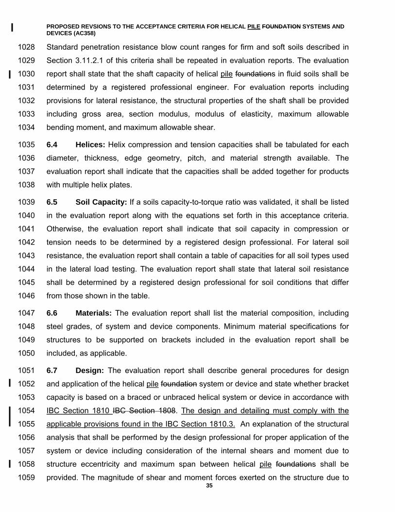
PROPOSED REVSIONS TO THE ACCEPTANCE CRITERIA FOR HELICAL PILE FOUNDATION SYSTEMS AND DEVICES (AC358)
35
Standard penetration resistance blow count ranges for firm and soft soils described in 1028
Section 3.11.2.1 of this criteria shall be repeated in evaluation reports. The evaluation 1029
report shall state that the shaft capacity of helical pile foundations in fluid soils shall be 1030
determined by a registered professional engineer. For evaluation reports including 1031
provisions for lateral resistance, the structural properties of the shaft shall be provided 1032
including gross area, section modulus, modulus of elasticity, maximum allowable 1033
bending moment, and maximum allowable shear. 1034
6.4 Helices: Helix compression and tension capacities shall be tabulated for each 1035
diameter, thickness, edge geometry, pitch, and material strength available. The 1036
evaluation report shall indicate that the capacities shall be added together for products 1037
with multiple helix plates. 1038
6.5 Soil Capacity: If a soils capacity-to-torque ratio was validated, it shall be listed 1039
in the evaluation report along with the equations set forth in this acceptance criteria. 1040
Otherwise, the evaluation report shall indicate that soil capacity in compression or 1041
tension needs to be determined by a registered design professional. For lateral soil 1042
resistance, the evaluation report shall contain a table of capacities for all soil types used 1043
in the lateral load testing. The evaluation report shall state that lateral soil resistance 1044
shall be determined by a registered design professional for soil conditions that differ 1045
from those shown in the table. 1046
6.6 Materials: The evaluation report shall list the material composition, including 1047
steel grades, of system and device components. Minimum material specifications for 1048
structures to be supported on brackets included in the evaluation report shall be 1049
included, as applicable. 1050
6.7 Design: The evaluation report shall describe general procedures for design 1051
and application of the helical pile foundation system or device and state whether bracket 1052
capacity is based on a braced or unbraced helical system or device in accordance with 1053
IBC Section 1810 IBC Section 1808. The design and detailing must comply with the 1054
applicable provisions found in the IBC Section 1810.3. An explanation of the structural 1055
analysis that shall be performed by the design professional for proper application of the 1056
system or device including consideration of the internal shears and moment due to 1057
structure eccentricity and maximum span between helical pile foundations shall be 1058
provided. The magnitude of shear and moment forces exerted on the structure due to 1059
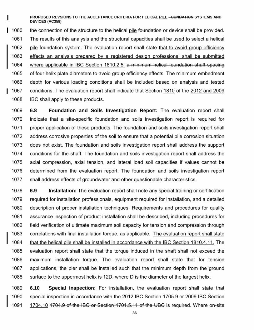
PROPOSED REVSIONS TO THE ACCEPTANCE CRITERIA FOR HELICAL PILE FOUNDATION SYSTEMS AND DEVICES (AC358)
36
the connection of the structure to the helical pile foundation or device shall be provided. 1060
The results of this analysis and the structural capacities shall be used to select a helical 1061
pile foundation system. The evaluation report shall state that to avoid group efficiency 1062
effects an analysis prepared by a registered design professional shall be submitted 1063
where applicable in IBC Section 1810.2.5. a minimum helical foundation shaft spacing 1064
of four helix plate diameters to avoid group efficiency effects. The minimum embedment 1065
depth for various loading conditions shall be included based on analysis and tested 1066
conditions. The evaluation report shall indicate that Section 1810 of the 2012 and 2009 1067
IBC shall apply to these products. 1068
6.8 Foundation and Soils Investigation Report: The evaluation report shall 1069
indicate that a site-specific foundation and soils investigation report is required for 1070
proper application of these products. The foundation and soils investigation report shall 1071
address corrosive properties of the soil to ensure that a potential pile corrosion situation 1072
does not exist. The foundation and soils investigation report shall address the support 1073
conditions for the shaft. The foundation and soils investigation report shall address the 1074
axial compression, axial tension, and lateral load soil capacities if values cannot be 1075
determined from the evaluation report. The foundation and soils investigation report 1076
shall address effects of groundwater and other questionable characteristics. 1077
6.9 Installation: The evaluation report shall note any special training or certification 1078
required for installation professionals, equipment required for installation, and a detailed 1079
description of proper installation techniques. Requirements and procedures for quality 1080
assurance inspection of product installation shall be described, including procedures for 1081
field verification of ultimate maximum soil capacity for tension and compression through 1082
correlations with final installation torque, as applicable. The evaluation report shall state 1083
that the helical pile shall be installed in accordance with the IBC Section 1810.4.11. The 1084
evaluation report shall state that the torque induced in the shaft shall not exceed the 1085
maximum installation torque. The evaluation report shall state that for tension 1086
applications, the pier shall be installed such that the minimum depth from the ground 1087
surface to the uppermost helix is 12D, where D is the diameter of the largest helix. 1088
6.10 Special Inspection: For installation, the evaluation report shall state that 1089
special inspection in accordance with the 2012 IBC Section 1705.9 or 2009 IBC Section 1090
1704.10 1704.9 of the IBC or Section 1701.5.11 of the UBC is required. Where on-site 1091
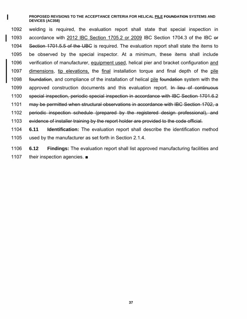
PROPOSED REVSIONS TO THE ACCEPTANCE CRITERIA FOR HELICAL PILE FOUNDATION SYSTEMS AND DEVICES (AC358)
37
welding is required, the evaluation report shall state that special inspection in 1092
accordance with 2012 IBC Section 1705.2 or 2009 IBC Section 1704.3 of the IBC or 1093
Section 1701.5.5 of the UBC is required. The evaluation report shall state the items to 1094
be observed by the special inspector. At a minimum, these items shall include 1095
verification of manufacturer, equipment used, helical pier and bracket configuration and 1096
dimensions, tip elevations, the final installation torque and final depth of the pile 1097
foundation, and compliance of the installation of helical pile foundation system with the 1098
approved construction documents and this evaluation report. In lieu of continuous 1099
special inspection, periodic special inspection in accordance with IBC Section 1701.6.2 1100
may be permitted when structural observations in accordance with IBC Section 1702, a 1101
periodic inspection schedule (prepared by the registered design professional), and 1102
evidence of installer training by the report holder are provided to the code official. 1103
6.11 Identification: The evaluation report shall describe the identification method 1104
used by the manufacturer as set forth in Section 2.1.4. 1105
6.12 Findings: The evaluation report shall list approved manufacturing facilities and 1106
their inspection agencies. ■ 1107
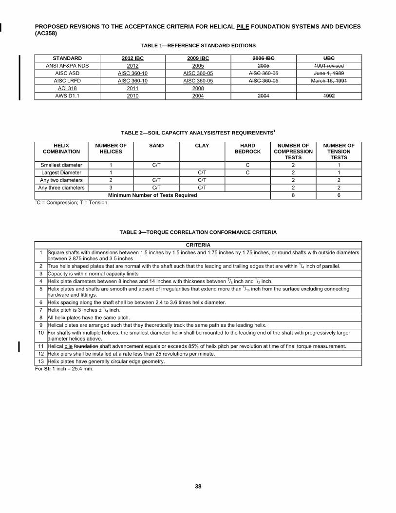
PROPOSED REVSIONS TO THE ACCEPTANCE CRITERIA FOR HELICAL PILE FOUNDATION SYSTEMS AND DEVICES (AC358)
38
TABLE 1—REFERENCE STANDARD EDITIONS
STANDARD 2012 IBC 2009 IBC 2006 IBC UBC
ANSI AF&PA NDS 2012 2005 2005 1991 revised
AISC ASD AISC 360-10 AISC 360-05 AiSC 360-05 June 1, 1989
AISC LRFD AISC 360-10 AISC 360-05 AISC 360-05 March 16, 1991
ACI 318 2011 2008
AWS D1.1 2010 2004 2004 1992
TABLE 2—SOIL CAPACITY ANALYSIS/TEST REQUIREMENTS1
HELIX
COMBINATION NUMBER OF
HELICES SAND CLAY HARD
BEDROCK NUMBER OF
COMPRESSION TESTS
NUMBER OF TENSION
TESTS
Smallest diameter 1 C/T C 2 1
Largest Diameter 1 C/T C 2 1
Any two diameters 2 C/T C/T 2 2
Any three diameters 3 C/T C/T 2 2
Minimum Number of Tests Required 8 6 1C = Compression; T = Tension.
TABLE 3—TORQUE CORRELATION CONFORMANCE CRITERIA
CRITERIA
1 Square shafts with dimensions between 1.5 inches by 1.5 inches and 1.75 inches by 1.75 inches, or round shafts with outside diameters between 2.875 inches and 3.5 inches
2 True helix shaped plates that are normal with the shaft such that the leading and trailing edges that are within 1/4 inch of parallel.
3 Capacity is within normal capacity limits
4 Helix plate diameters between 8 inches and 14 inches with thickness between 3/8 inch and 1/2 inch.
5 Helix plates and shafts are smooth and absent of irregularities that extend more than 1/16 inch from the surface excluding connecting hardware and fittings.
6 Helix spacing along the shaft shall be between 2.4 to 3.6 times helix diameter.
7 Helix pitch is 3 inches ± 1/4 inch.
8 All helix plates have the same pitch.
9 Helical plates are arranged such that they theoretically track the same path as the leading helix.
10 For shafts with multiple helices, the smallest diameter helix shall be mounted to the leading end of the shaft with progressively larger diameter helices above.
11 Helical pile foundation shaft advancement equals or exceeds 85% of helix pitch per revolution at time of final torque measurement.
12 Helix piers shall be installed at a rate less than 25 revolutions per minute.
13 Helix plates have generally circular edge geometry.
For SI: 1 inch = 25.4 mm.
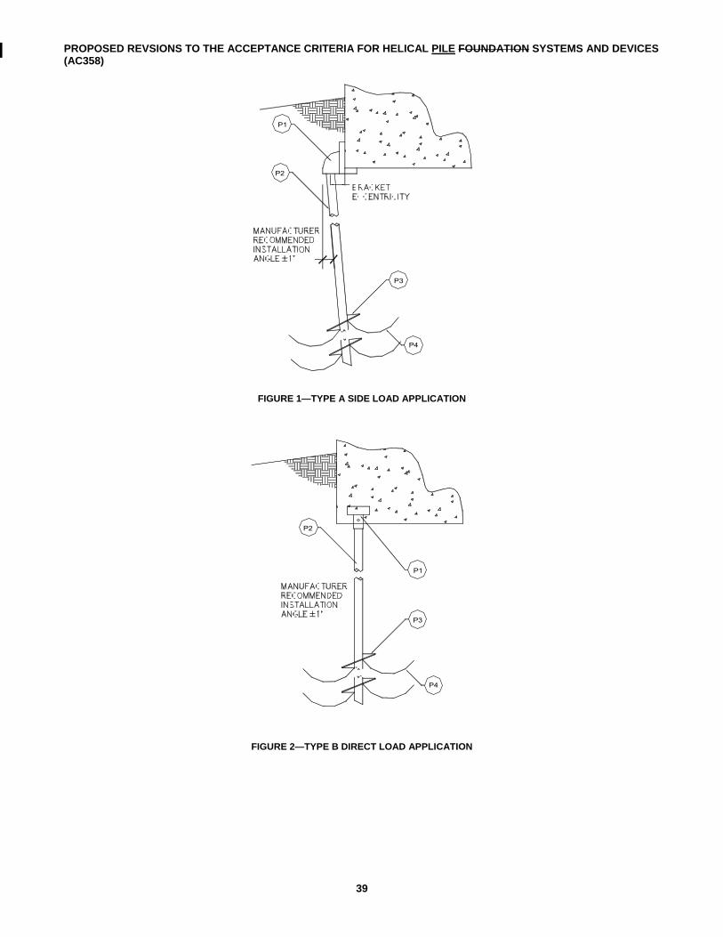
PROPOSED REVSIONS TO THE ACCEPTANCE CRITERIA FOR HELICAL PILE FOUNDATION SYSTEMS AND DEVICES (AC358)
39
FIGURE 1—TYPE A SIDE LOAD APPLICATION
FIGURE 2—TYPE B DIRECT LOAD APPLICATION
P1
P2
P3
P4
P1
P2
P3
P4
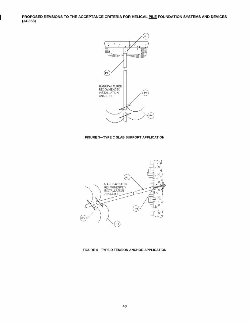
PROPOSED REVSIONS TO THE ACCEPTANCE CRITERIA FOR HELICAL PILE FOUNDATION SYSTEMS AND DEVICES (AC358)
40
FIGURE 3—TYPE C SLAB SUPPORT APPLICATION
FIGURE 4—TYPE D TENSION ANCHOR APPLICATION
P2
P3
P4
P1
P4
P3
P2
P1
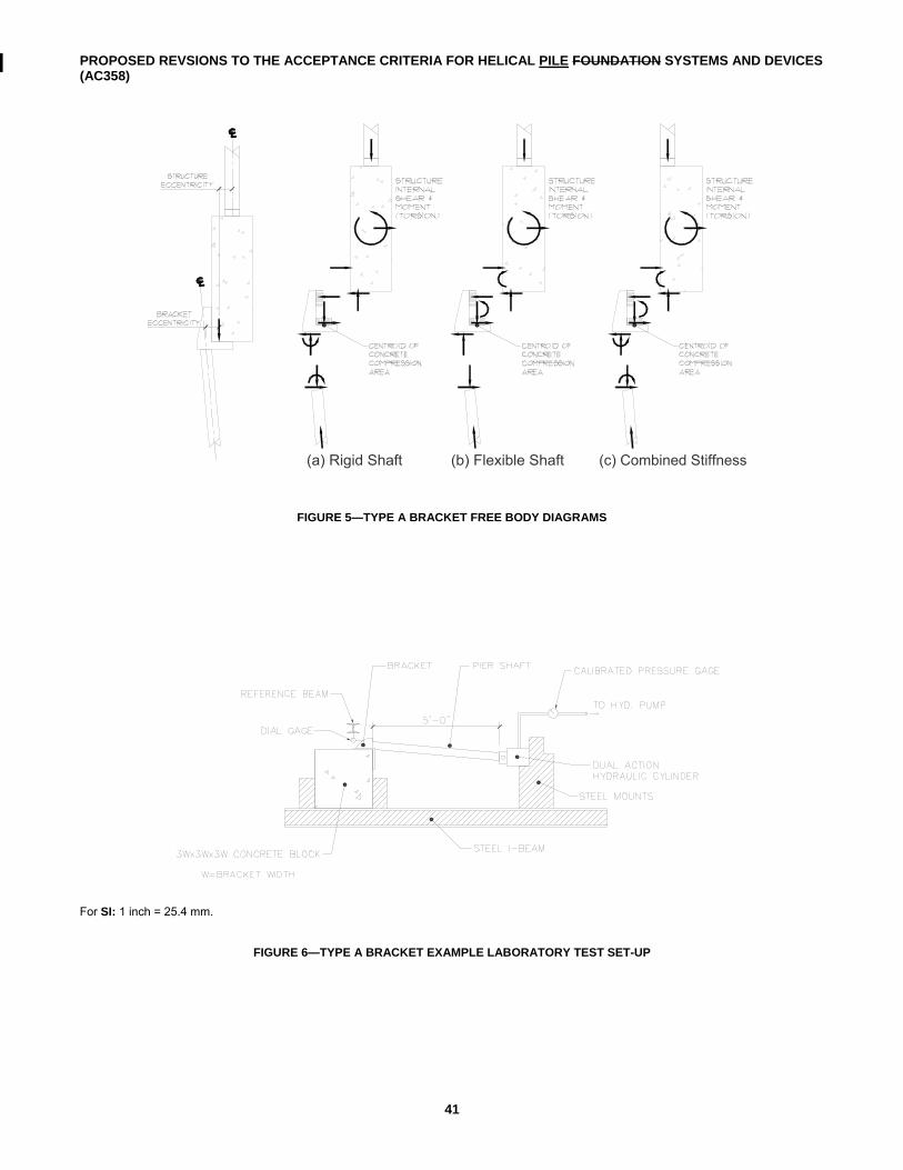
PROPOSED REVSIONS TO THE ACCEPTANCE CRITERIA FOR HELICAL PILE FOUNDATION SYSTEMS AND DEVICES (AC358)
41
FIGURE 5—TYPE A BRACKET FREE BODY DIAGRAMS
For SI: 1 inch = 25.4 mm.
FIGURE 6—TYPE A BRACKET EXAMPLE LABORATORY TEST SET-UP
(a) Rigid Shaft (b) Flexible Shaft (c) Combined Stiffness
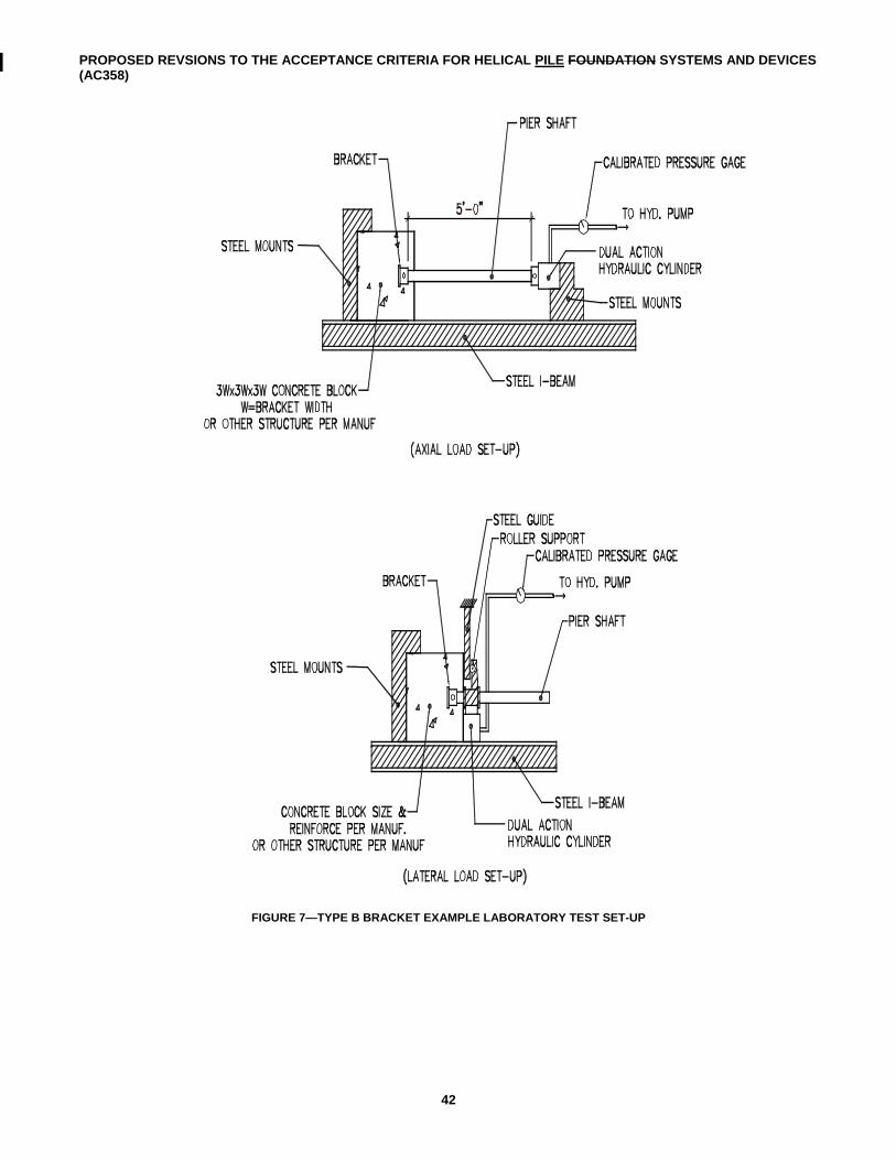
PROPOSED REVSIONS TO THE ACCEPTANCE CRITERIA FOR HELICAL PILE FOUNDATION SYSTEMS AND DEVICES (AC358)
42
FIGURE 7—TYPE B BRACKET EXAMPLE LABORATORY TEST SET-UP
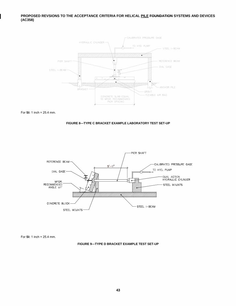
PROPOSED REVSIONS TO THE ACCEPTANCE CRITERIA FOR HELICAL PILE FOUNDATION SYSTEMS AND DEVICES (AC358)
43
For SI: 1 inch = 25.4 mm.
FIGURE 8—TYPE C BRACKET EXAMPLE LABORATORY TEST SET-UP
For SI: 1 inch = 25.4 mm.
FIGURE 9—TYPE D BRACKET EXAMPLE TEST SET-UP
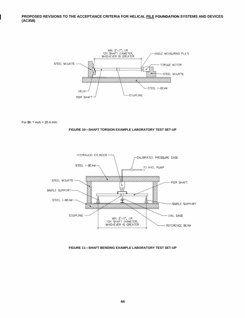
PROPOSED REVSIONS TO THE ACCEPTANCE CRITERIA FOR HELICAL PILE FOUNDATION SYSTEMS AND DEVICES (AC358)
44
For SI: 1 inch = 25.4 mm.
FIGURE 10—SHAFT TORSION EXAMPLE LABORATORY TEST SET-UP
FIGURE 11—SHAFT BENDING EXAMPLE LABORATORY TEST SET-UP
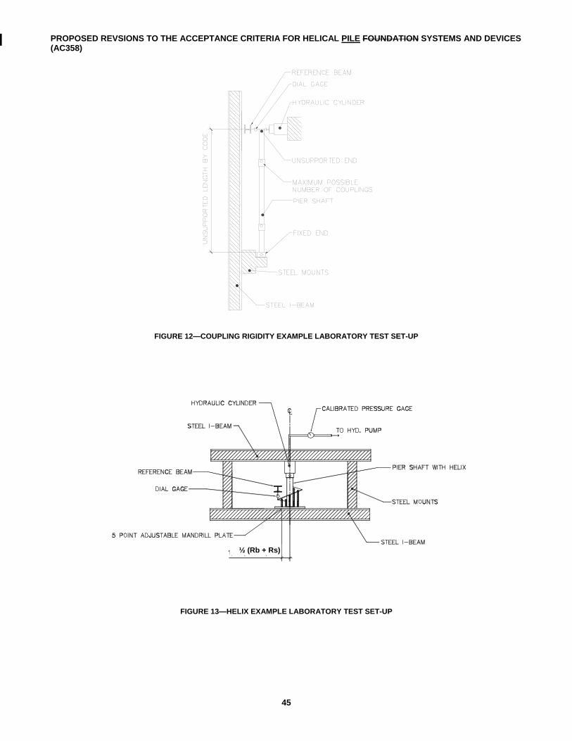
PROPOSED REVSIONS TO THE ACCEPTANCE CRITERIA FOR HELICAL PILE FOUNDATION SYSTEMS AND DEVICES (AC358)
45
FIGURE 12—COUPLING RIGIDITY EXAMPLE LABORATORY TEST SET-UP
FIGURE 13—HELIX EXAMPLE LABORATORY TEST SET-UP
½ (Rb + Rs)