Embed Size (px)
Citation preview
3867
en
- 201
1.03
/ g
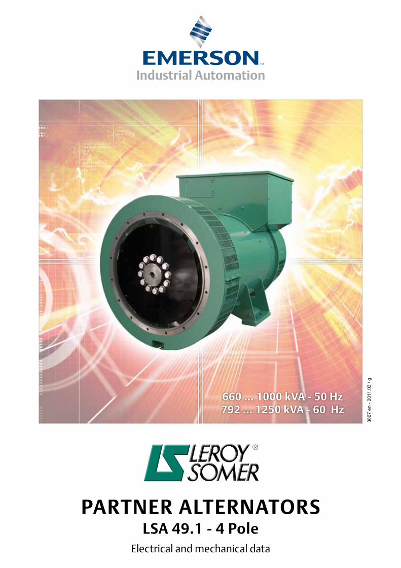
PARTNER ALTERNATORSLSA 49.1 - 4 Pole
Electrical and mechanical data
660 … 1000 kVA - 50 Hz792 … 1250 kVA - 60 Hz
2
LSA 49.1 - 4 Pole
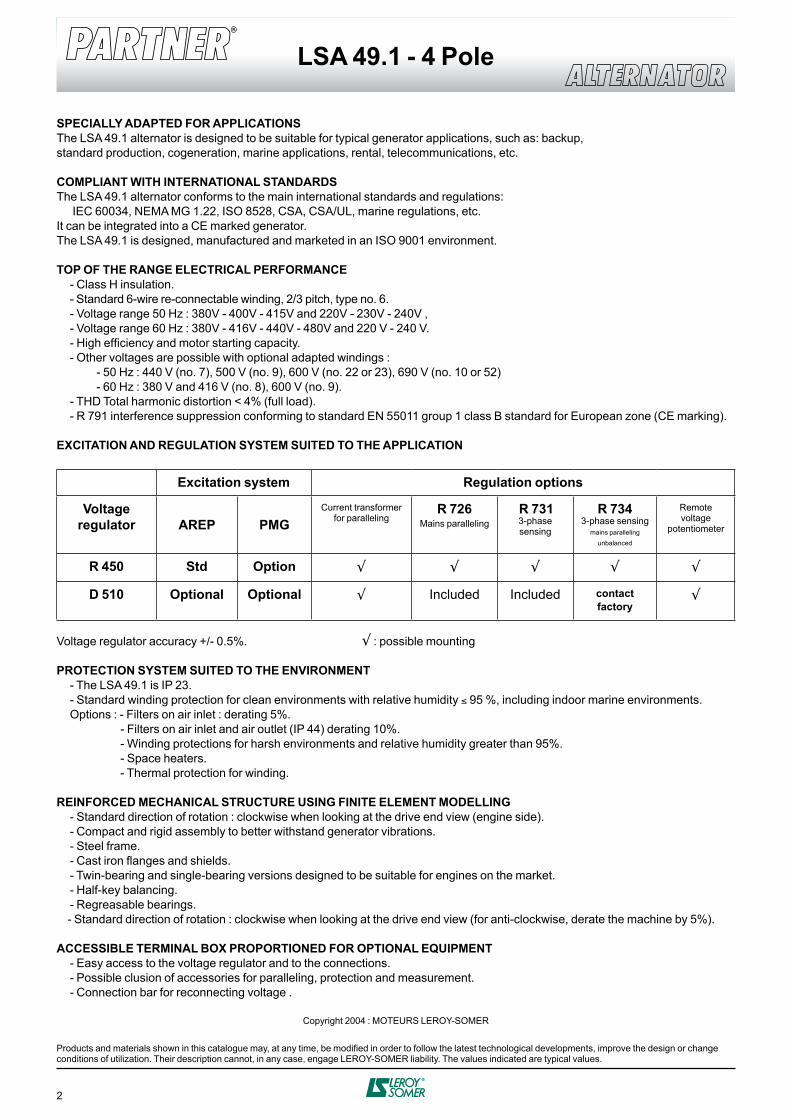
SPECIALLY ADAPTED FOR APPLICATIONSThe LSA 49.1 alternator is designed to be suitable for typical generator applications, such as: backup,standard production, cogeneration, marine applications, rental, telecommunications, etc.
COMPLIANT WITH INTERNATIONAL STANDARDSThe LSA 49.1 alternator conforms to the main international standards and regulations: IEC 60034, NEMA MG 1.22, ISO 8528, CSA, CSA/UL, marine regulations, etc.It can be integrated into a CE marked generator.The LSA 49.1 is designed, manufactured and marketed in an ISO 9001 environment.
TOP OF THE RANGE ELECTRICAL PERFORMANCE - Class H insulation. - Standard 6-wire re-connectable winding, 2/3 pitch, type no. 6. - Voltage range 50 Hz : 380V - 400V - 415V and 220V - 230V - 240V , - Voltage range 60 Hz : 380V - 416V - 440V - 480V and 220 V - 240 V. - High efficiency and motor starting capacity. - Other voltages are possible with optional adapted windings : - 50 Hz : 440 V (no. 7), 500 V (no. 9), 600 V (no. 22 or 23), 690 V (no. 10 or 52) - 60 Hz : 380 V and 416 V (no. 8), 600 V (no. 9). - THD Total harmonic distortion < 4% (full load). - R 791 interference suppression conforming to standard EN 55011 group 1 class B standard for European zone (CE marking).
EXCITATION AND REGULATION SYSTEM SUITED TO THE APPLICATION
Excitation system Regulation options
Voltageregulator AREP PMG
Current transformer for paralleling
R 726Mains paralleling
R 7313-phase sensing
R 7343-phase sensing
mains parallelingunbalanced
Remote voltage
potentiometer
R 450 Std Option √ √ √ √ √
D 510 Optional Optional √ Included Included contactfactory
√
Voltage regulator accuracy +/- 0.5%. √ : possible mounting
PROTECTION SYSTEM SUITED TO THE ENVIRONMENT - The LSA 49.1 is IP 23. - Standard winding protection for clean environments with relative humidity ≤ 95 %, including indoor marine environments. Options : - Filters on air inlet : derating 5%. - Filters on air inlet and air outlet (IP 44) derating 10%. - Winding protections for harsh environments and relative humidity greater than 95%. - Space heaters. - Thermal protection for winding. REINFORCED MECHANICAL STRUCTURE USING FINITE ELEMENT MODELLING - Standard direction of rotation : clockwise when looking at the drive end view (engine side). - Compact and rigid assembly to better withstand generator vibrations. - Steel frame. - Cast iron flanges and shields. - Twin-bearing and single-bearing versions designed to be suitable for engines on the market. - Half-key balancing. - Regreasable bearings. - Standard direction of rotation : clockwise when looking at the drive end view (for anti-clockwise, derate the machine by 5%).
ACCESSIBLE TERMINAL BOX PROPORTIONED FOR OPTIONAL EQUIPMENT - Easy access to the voltage regulator and to the connections. - Possible clusion of accessories for paralleling, protection and measurement. - Connection bar for reconnecting voltage .
Copyright 2004 : MOTEURS LEROY-SOMER
Products and materials shown in this catalogue may, at any time, be modified in order to follow the latest technological developments, improve the design or change conditions of utilization. Their description cannot, in any case, engage LEROY-SOMER liability. The values indicated are typical values.
3
LSA 49.1 - 4 Pole
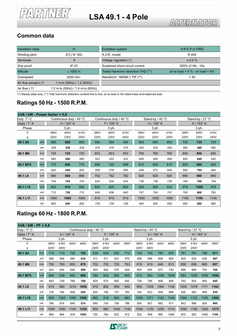
Common data
Insulation class H Excitation system A R E P or PMG
Winding pitch 2/3 ( N° 6S) A.V.R. model R 450
Terminals 6 Voltage regulation (*) ± 0,5 %
Drip proof IP 23 Sustained short-circuit current 300% (3 IN) : 10s
Altitude ≤ 1000 m Totale Harmonic distortion THD (**) at no load < 4 % - on load < 4%
Overspeed 2250 min-1 Waveform : NEMA = TIF (**) < 50
Air flow except L11 1 m3/s (50Hz) / 1,2 (60Hz)
Air flow L11 1.2 m3/s (50Hz) / 1,4 m3/s (60Hz)
(*) Steady state duty. (**) Total harmonic distortion content line to line, at no load or full rated linear and balanced load.
Ratings 60 Hz - 1800 R.P.M.
Ratings 50 Hz - 1500 R.P.M.
kVA / kW - Power factor = 0,8Duty T° C Continuous duty / 40 °C Continuous duty / 40 °C Stand-by / 40 °C Stand-by / 27 °CClass / T° K H / 125° K F / 105° K H / 150° K H / 163° K
Phase 3 ph. 3 ph. 3 ph. 3 ph.Y 380V 400V 415V 380V 400V 415V 380V 400V 415V 380V 400V 415VD 220V 230V 240V 220V 230V 240V 220V 230V 240V 220V 230V 240V
49.1 S4 kVA 660 660 660 594 594 594 693 693 693 725 725 725kW 528 528 528 475 475 475 554 554 554 580 580 580
49.1 M6 kVA 725 725 725 653 653 653 760 760 760 800 800 800kW 580 580 580 522 522 522 608 608 608 640 640 640
49.1 M75 kVA 775 800 775 698 720 698 810 840 810 850 880 850kW 620 640 620 558 576 558 648 672 648 680 704 680
49.1 L9 kVA 880 880 880 792 792 792 920 920 920 960 960 960kW 704 704 704 634 634 634 736 736 736 768 768 768
49.1 L10 kVA 890 910 890 800 820 800 934 955 934 979 1000 979kW 712 728 712 640 656 640 747 764 747 783 800 783
49.1 L11 kVA 1000 1000 1000 910 910 910 1050 1050 1050 1100 1100 1100kW 800 800 800 728 728 728 840 840 840 880 880 880
kVA / kW - PF = 0,8Duty / T° C Continuous duty / 40 °C Stand-by / 40 °C Stand-by / 27 °CClass / T° K H / 125° K F / 105° K H / 150° K H / 163° K
Phase 3 ph. 3 ph. 3 ph. 3 ph.Y 380V 416V 440V 480V 380V 416V 440V 480V 380V 416V 440V 480V 380V 416V 440V 480VD 220V 240V 220V 240V 220V 240V 220V 240V
49.1 S4 kVA 710 710 725 792 639 639 652 712 745 745 760 830 781 781 798 871kW 568 568 580 634 511 511 522 570 596 596 608 664 625 625 638 697
49.1 M6 kVA 780 780 800 870 702 702 720 783 819 819 840 913 858 858 880 957kW 624 624 640 696 562 562 576 626 655 655 672 730 686 686 704 766
49.1 M75 kVA 866 936 960 960 780 842 865 865 910 983 1008 1008 953 1030 1056 1056kW 693 749 768 768 624 674 692 692 728 786 806 806 762 824 845 845
49.1 L9 kVA 910 980 1010 1056 819 882 909 950 955 1029 1060 1108 1000 1078 1111 1162kW 728 784 808 845 655 706 727 760 764 823 848 886 800 862 889 930
49.1 L10 kVA 958 1020 1050 1092 862 918 945 983 1006 1071 1102 1146 1054 1122 1155 1200kW 766 816 840 874 690 734 756 786 805 857 882 917 843 898 924 960
49.1 L11 kVA 1000 1080 1145 1250 900 980 1040 1140 1040 1135 1200 1310 1090 1190 1260 1375kW 800 864 916 1000 720 784 832 912 832 908 960 1048 872 952 1008 1100
4
LSA 49.1 - 4 Pole
97%
96
95
94
93
92100 200 300 400 500 600 700 800 kVA
93.7
95.896.1
96
94.6
95.8
92.9
94.5 93.9
93.7
LSA 49.1 S4
P.F. : 1
P.F. : 0,8
97%
96
95
94
93
92100 200 300 400 500 600 700 800 kVA
93.8
9696.4
96.3
94.9
96.2
93
95 94.6
94.4
LSA 49.1 M6
P.F. : 1
P.F. : 0,8
97%
96
95
94
93
92100 200 300 400 500 600 700 800 900 1000kVA
94.2
96.196.4
96.2
95
96.1
93.4
94.9 94.4
94.1
LSA 49.1 M75
P.F. : 1
P.F. : 0,8
97%
96
95
94
93
92100 200 300 400 500 600 700 800 900 1000 kVA
94.3
96.4 96.7
96.7
95.4
96.6
93.7
95.595.2
95
LSA 49.1 L9 P.F. : 1
P.F. : 0,8
100 200 300 400 500 600 700 800 900 1000 kVA
94.5
96.496.7
96.7
95.4
96.6
93.8
95.595.1
94.9
LSA 49.1 L10 P.F. : 1
P.F. : 0,8
97%
96
95
94
93
92
97%
96
95
94
93
92100 200 300 400 500 600 700 800 900 1000 1100 kVA
94.4
96.396.7
96.6
95.4
96.5
93.8
95.4 95
94.8
LSA 49.1 L11 P.F. : 1
P.F. : 0,8
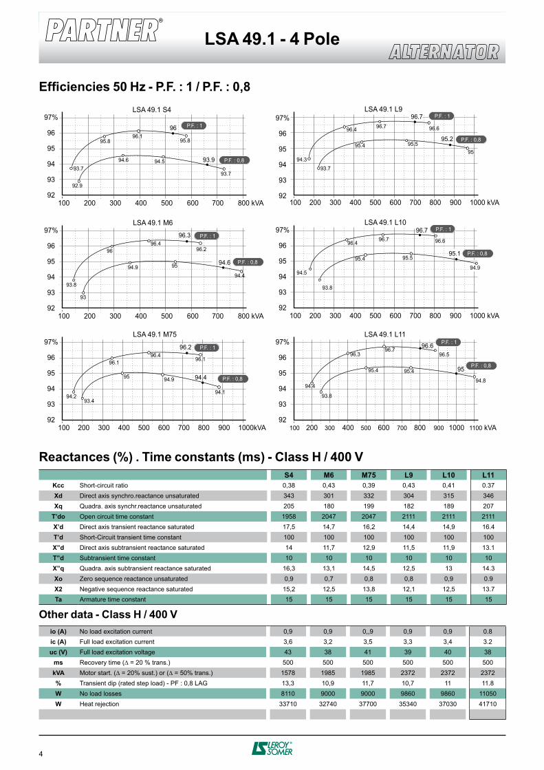
Efficiencies 50 Hz - P.F. : 1 / P.F. : 0,8
Reactances (%) . Time constants (ms) - Class H / 400 VS4 M6 M75 L9 L10 L11
Kcc Short-circuit ratio 0,38 0,43 0,39 0,43 0,41 0.37Xd Direct axis synchro.reactance unsaturated 343 301 332 304 315 346Xq Quadra. axis synchr.reactance unsaturated 205 180 199 182 189 207
T’do Open circuit time constant 1958 2047 2047 2111 2111 2111X’d Direct axis transient reactance saturated 17,5 14,7 16,2 14,4 14,9 16.4T’d Short-Circuit transient time constant 100 100 100 100 100 100X”d Direct axis subtransient reactance saturated 14 11,7 12,9 11,5 11,9 13.1T”d Subtransient time constant 10 10 10 10 10 10X”q Quadra. axis subtransient reactance saturated 16,3 13,1 14,5 12,5 13 14.3Xo Zero sequence reactance unsaturated 0,9 0,7 0,8 0,8 0,9 0.9X2 Negative sequence reactance saturated 15,2 12,5 13,8 12,1 12,5 13.7Ta Armature time constant 15 15 15 15 15 15
Other data - Class H / 400 V io (A) No load excitation current 0,9 0,9 0,,9 0,9 0,9 0.8ic (A) Full load excitation current 3,6 3,2 3,5 3,3 3,4 3.2uc (V) Full load excitation voltage 43 38 41 39 40 38
ms Recovery time (∆ = 20 % trans.) 500 500 500 500 500 500kVA Motor start. (∆ = 20% sust.) or (∆ = 50% trans.) 1578 1985 1985 2372 2372 2372% Transient dip (rated step load) - PF : 0,8 LAG 13,3 10,9 11,7 10,7 11 11.8W No load losses 8110 9000 9000 9860 9860 11050W Heat rejection 33710 32740 37700 35340 37030 41710
5
LSA 49.1 - 4 Pole
S 4
M 6
L 9
20 %
15
10
5
0
M 75
L 10
0 250 500 750 1000 1250 1500 1750 2000 2250 2500 kVA
30%
25
20
15
10
5
0
0 100 200 300 400 500 600 700 800 900 1000 kVA
0 100 200 300 400 500 600 700 800 900 1000 kVA
S 4
S 4
M 6
M 6 L 9
20 %
15
10
5
0
M 75
M 75
L 10
L 9
L 10
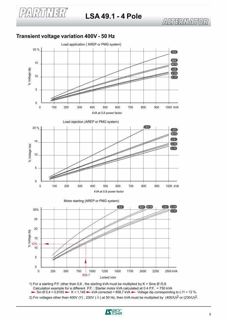
Load application ( AREP or PMG system)
kVA at 0,8 power factor
kVA at 0,8 power factor
% V
olta
ge d
ip
Load rejection (AREP or PMG system)
% V
olta
ge ri
se%
Vol
tage
dip
Motor starting (AREP or PMG system)
Locked rotor
Calculation example for a different P.F. : Starter motor kVA calculated at 0.4 P.F. = 750 kVA Sin Ø 0,4 = 0,9165 K = 1,145 kVA corrected = 858,7 kVA Voltage dip corresponding to L11 = 12 %.
1) For a starting P.F. other than 0,6 , the starting kVA must be multiplied by K = Sine Ø /0,8
2) For voltages other than 400V (Y) , 230V ( ) at 50 Hz, then kVA must be multiplied by (400/U)2 or (230/U)2.
L 11
L 11
L 11
12%
858.7
Transient voltage variation 400V - 50 Hz
6
LSA 49.1 - 4 Pole
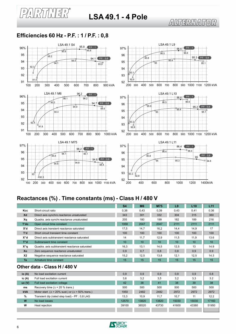
Efficiencies 60 Hz - P.F. : 1 / P.F. : 0,8
96%
95
94
93
92
91
96%
95
94
93
92
91
100 200 300 400 500 600 700 800 900 kVA
92.3
95.2
95.8
95.9
94.1
95.8
91.6
94.494.1
93.9
LSA 49.1 S4 P.F. : 1
P.F. : 0,8
97%
96
95
94
93
92100 200 300 400 500 600 700 800 900 1000 1100 kVA
93
95.696.1
96.2
94.6
96.1
92.3
94.894.6
94.4
LSA 49.1 M75
P.F. : 1
P.F. : 0,8
97%
96
95
94
93
92200 300 400 500 600 700 800 900 1000 1100 1200 kVA
93.1
95.8
96.5
96.6
95
96.6
92,6
95.495.3
95.1
LSA 49.1 L9 P.F. : 1
P.F. : 0,8
P.F. : 0,8
97%
96
95
94
93
92200 300 400 500 600 700 800 900 1000 1100 1200 kVA
93.3
95.996.5
96.6
95
96.6
92,8
95.495.2
95.1
P.F. : 1
P.F. : 1
P.F. : 0,8
LSA 49.1 L10
100 200 300 400 500 600 700 800 900 1000 kVA
92.4
95.396.1
96.2
94.4
96.2
91.8
94.994.7
94.6
LSA 49.1 M6 P.F. : 1
P.F. : 0,8
97%
96
95
94
93
92200 400 600 800 1000 1200 1400kVA
93.3
95.8
96.4
96.4
95
96.4
92,8
95.395
94.8
LSA 49.1 L11
Reactances (%) . Time constants (ms) - Class H / 480 V
Other data - Class H / 480 V
S4 M6 M75 L9 L10 L11Kcc Short-circuit ratio 0,38 0,43 0,39 0,43 0,41 0.36Xd Direct axis synchro.reactance unsaturated 343 301 332 304 315 360Xq Quadra. axis synchr.reactance unsaturated 205 180 199 182 189 216
T’do Open circuit time constant 1958 2047 2047 2111 2111 2111X’d Direct axis transient reactance saturated 17,5 14,7 16,2 14,4 14,9 17T’d Short circuit transient time constant 100 100 100 100 100 100X”d Direct axis subtransient reactance saturated 14 11,7 12,9 11,5 11,9 13.6T”d Subtransient time constant 10 10 10 10 10 10X”q Quadra. axis subtransient reactance saturated 16,3 13,1 14,5 12,5 13 14.9Xo Zero sequence reactance unsaturated 0,9 0,7 0,8 0,8 0,9 0.9X2 Negative sequence reactance saturated 15,2 12,5 13,8 12,1 12,5 14.3Ta Armature time constant 15 15 15 15 15 15
io (A) No load excitation current 0,9 0,9 0,9 0,9 0,9 0.8ic (A) Full load excitation current 3,6 3,2 3,5 3,2 3,3 3.2uc (V) Full load excitation voltage 42 38 41 38 39 38
ms Recovery time (∆ = 20 % trans.) 500 500 500 500 500 500kVA Motor start. (∆ = 20% sust.) or (∆ = 50% trans.) 1950 2482 2482 2972 2972 2972% Transient dip (rated step load) - PF : 0,8 LAG 13,3 10,9 11,7 10,7 11 12.2W No load losses 12570 13820 13820 15030 15030 17160W Heat rejection 39100 38520 43730 41600 43380 51950
7
LSA 49.1 - 4 Pole
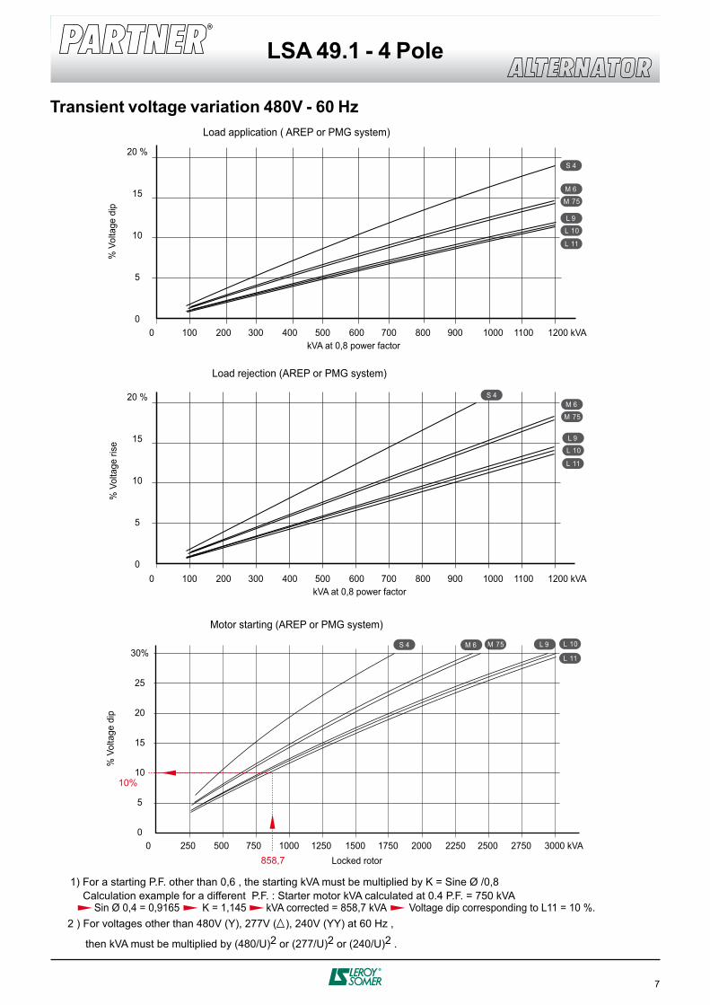
Transient voltage variation 480V - 60 Hz
0 100 200 300 400 500 600 700 800 900 1000 1100 1200 kVA
0 100 200 300 400 500 600 700 800 900 1000 1100 1200 kVA
S 4
M 6
L 9
20 %
15
10
5
0
M 75
L 10
L 11
L 11
0 250 500 750 1000 1250 1500 1750 2000 2250 2500 2750 3000 kVA
30%
25
20
15
10
5
0
S 4
S 4 M 6 L 9
20 %
15
10
5
0
M 6
L 9
M 75
M 75
L 10
L 10
L 11
10%
858,7
Load application ( AREP or PMG system)
kVA at 0,8 power factor
kVA at 0,8 power factor
% V
olta
ge d
ip
Load rejection (AREP or PMG system)
% V
olta
ge ri
se%
Vol
tage
dip
Motor starting (AREP or PMG system)
Locked rotor
2 ) For voltages other than 480V (Y), 277V ( ), 240V (YY) at 60 Hz ,
then kVA must be multiplied by (480/U)2 or (277/U)2 or (240/U)2 .
Calculation example for a different P.F. : Starter motor kVA calculated at 0.4 P.F. = 750 kVA Sin Ø 0,4 = 0,9165 K = 1,145 kVA corrected = 858,7 kVA Voltage dip corresponding to L11 = 10 %.
1) For a starting P.F. other than 0,6 , the starting kVA must be multiplied by K = Sine Ø /0,8
8
LSA 49.1 - 4 Pole
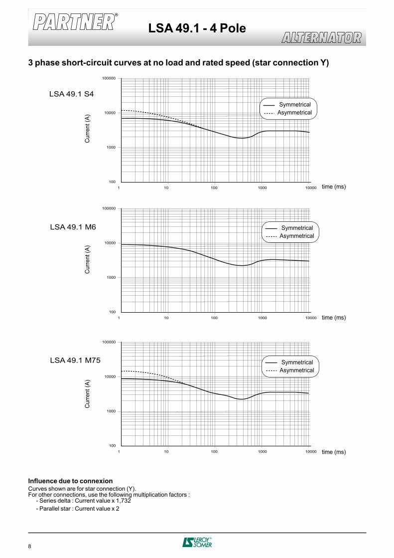
3 phase short-circuit curves at no load and rated speed (star connection Y)
LSA 49.1 S4
LSA 49.1 M75
1 10 100 1000 10000
100000
10000
1000
100
1 10 100 1000 10000
100000
10000
1000
100
LSA 49.1 M6
1 10 100 1000 10000
100000
10000
1000
100
Cur
rent
(A)
time (ms)
Symmetrical Asymmetrical
Cur
rent
(A)
time (ms)
Symmetrical Asymmetrical
Cur
rent
(A)
time (ms)
Symmetrical Asymmetrical
Influence due to connexionCurves shown are for star connection (Y).For other connections, use the following multiplication factors : - Series delta : Current value x 1,732 - Parallel star : Current value x 2
9
LSA 49.1 - 4 Pole
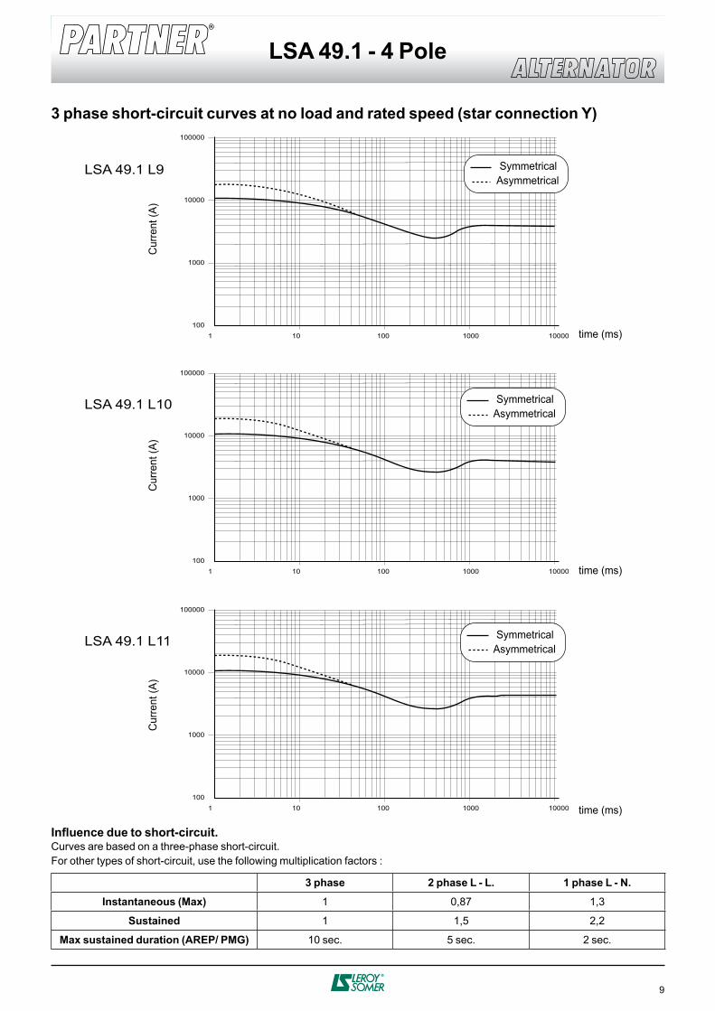
3 phase short-circuit curves at no load and rated speed (star connection Y)
LSA 49.1 L9
LSA 49.1 L10
1 10 100 1000 10000
100000
10000
1000
100
1 10 100 1000 10000
100000
10000
1000
100
Cur
rent
(A)
time (ms)
Symmetrical Asymmetrical
Cur
rent
(A)
Cur
rent
(A)
time (ms)
time (ms)
Symmetrical Asymmetrical
LSA 49.1 L11
1 10 100 1000 10000
100000
10000
1000
100
Symmetrical Asymmetrical
Influence due to short-circuit.Curves are based on a three-phase short-circuit.For other types of short-circuit, use the following multiplication factors :
3 phase 2 phase L - L. 1 phase L - N.
Instantaneous (Max) 1 0,87 1,3
Sustained 1 1,5 2,2
Max sustained duration (AREP/ PMG) 10 sec. 5 sec. 2 sec.
10
LSA 49.1 - 4 Pole
L
C 216
LBXg
Ø B
X
Ø N
Ø P
AH792
686 786
658
40
0
1058
27
Diodeaccess
11°15'
6
0 - 0,1
27
- 0,0
50- 0
,100
17
W
CF
626
Air inlet
2 x 2 hole Ø 35
Ø 7
42
37
85,3
300 281
AVRaccess
100
Ø 230
0 - 1
90
ROption
Ø 2
35
Option PMG
C
213,5
Xg
Air outlet Air outlet
Ø B
X
Ø N
Ø 8
83
AH
6
0 - 0,1
27
- 0,0
50- 0
,100
15,7
7
CF
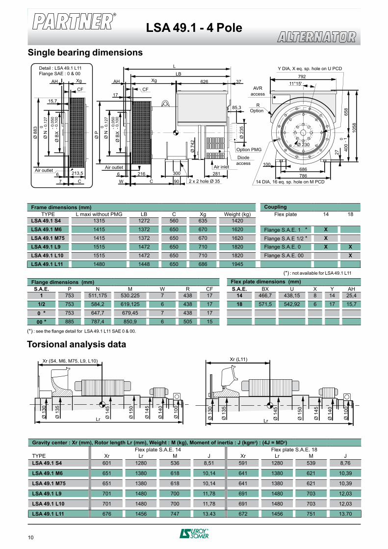
Detail : LSA 49.1 L11Flange SAE : 0 & 00
Y DIA, X eq. sp. hole on U PCD
14 DIA, 16 eq. sp. hole on M PCD
Torsional analysis data
Single bearing dimensions
Frame dimensions (mm) CouplingTYPE L maxi without PMG LB C Xg Weight (kg) Flex plate 14 18
LSA 49.1 S4 1315 1272 560 635 1420
LSA 49.1 M6 1415 1372 650 670 1620 Flange S.A.E. 1 * XLSA 49.1 M75 1415 1372 650 670 1620 Flange S.A.E 1/2 * XLSA 49.1 L9 1515 1472 650 710 1820 Flange S.A.E. 0 X XLSA 49.1 L10 1515 1472 650 710 1820 Flange S.A.E. 00 XLSA 49.1 L11 1480 1448 650 686 1945
Flange dimensions (mm) Flex plate dimensions (mm)S.A.E. P N M W R CF S.A.E. BX U X Y AH
1 753 511,175 530.225 7 438 17 14 466,7 438,15 8 14 25,4
1/2 753 584,2 619,125 6 438 17 18 571,5 542,92 6 17 15,7
0 * 753 647,7 679,45 7 438 17
00 * 885 787,4 850,9 6 505 15
(*) : not available for LSA 49.1 L11
(*) : see the flange detail for LSA 49.1 L11 SAE 0 & 00.
Ø 1
50
Ø 1
45
Ø 1
40
Ø 1
00
Xr (S4, M6, M75, L9, L10)
Lr Ø 1
45
Ø 1
35
Ø 1
30
Ø 1
50
Ø 1
45
Ø 1
40
Ø 1
00
Xr (L11)
Lr Ø 1
45
Ø 1
35
Ø 1
30
Gravity center : Xr (mm), Rotor length Lr (mm), Weight : M (kg), Moment of inertia : J (kgm2) : (4J = MD2)Flex plate S.A.E. 14 Flex plate S.A.E. 18
TYPE Xr Lr M J Xr Lr M J LSA 49.1 S4 601 1280 536 8,51 591 1280 539 8,76
LSA 49.1 M6 651 1380 618 10,14 641 1380 621 10,39
LSA 49.1 M75 651 1380 618 10,14 641 1380 621 10,39
LSA 49.1 L9 701 1480 700 11,78 691 1480 703 12,03
LSA 49.1 L10 701 1480 700 11,78 691 1480 703 12,03
LSA 49.1 L11 676 1456 747 13.43 672 1456 751 13.70
11
LSA 49.1 - 4 Pole
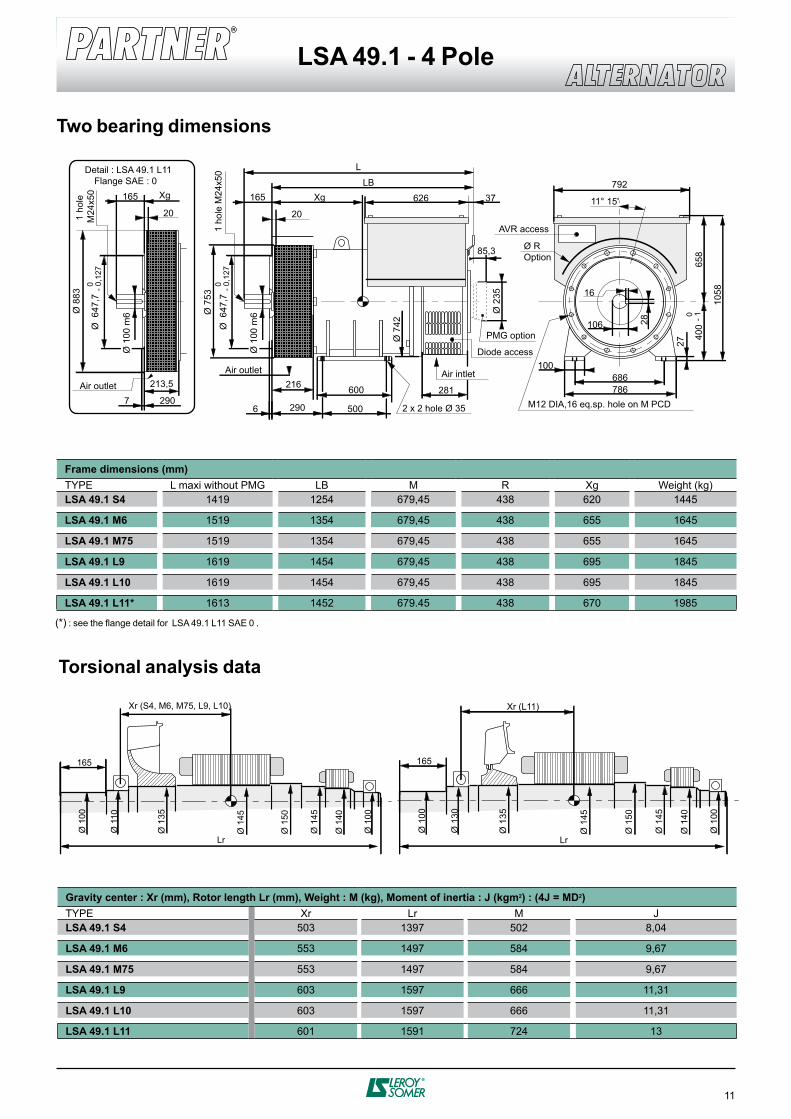
Two bearing dimensions
85,3
Ø 2
35
L
LBXg
Ø 7
53165165
792
686 786
658
40
0
1058
27
11° 15'
6
2020
Ø ROption
626
Ø 7
42
37
216 281
100
0 - 1
106 28
Ø 1
00 m
6
Ø 6
47,7
1 ho
le M
24x5
0
0 - 0,1
27
Ø 6
47,7
0 - 0,1
27
Ø 1
00 m
6
1 ho
le
M24
x50
2 x 2 hole Ø 35290290
500
600
16
213,5
Xg
Ø 8
83
7
Detail : LSA 49.1 L11Flange SAE : 0
Air outlet
Air outlet
Diode access
PMG option
Air intlet
AVR access
M12 DIA,16 eq.sp. hole on M PCD
Torsional analysis data
Frame dimensions (mm)TYPE L maxi without PMG LB M R Xg Weight (kg)LSA 49.1 S4 1419 1254 679,45 438 620 1445
LSA 49.1 M6 1519 1354 679,45 438 655 1645
LSA 49.1 M75 1519 1354 679,45 438 655 1645
LSA 49.1 L9 1619 1454 679,45 438 695 1845
LSA 49.1 L10 1619 1454 679,45 438 695 1845
LSA 49.1 L11* 1613 1452 679.45 438 670 1985
(*) : see the flange detail for LSA 49.1 L11 SAE 0 .
Gravity center : Xr (mm), Rotor length Lr (mm), Weight : M (kg), Moment of inertia : J (kgm2) : (4J = MD2)TYPE Xr Lr M J LSA 49.1 S4 503 1397 502 8,04
LSA 49.1 M6 553 1497 584 9,67
LSA 49.1 M75 553 1497 584 9,67
LSA 49.1 L9 603 1597 666 11,31
LSA 49.1 L10 603 1597 666 11,31
LSA 49.1 L11 601 1591 724 13
Ø 1
50
Ø 1
45
Ø 1
40
Ø 1
00
Xr (S4, M6, M75, L9, L10)
Lr
Ø 1
45
165
Ø 1
10
Ø 1
00
Ø 1
35
Ø 1
50
Ø 1
45
Ø 1
40
Ø 1
00Xr (L11)
Lr
Ø 1
45
165
Ø 1
30
Ø 1
00
Ø 1
35
www.leroy-somer.com
Contact
w w w . l e r o y - s o m e r . c o m
I n t e r n a t i o n a l n e t w o r k
ALGERIALEROY-SOMER International Division
AUSTRALIALEROY-SOMER PTY LTD
AUSTRIALEROY-SOMER ELEKTROMOTOREN
BELGIUMLEROY-SOMER BELGIUM
BRAZILLEROY-SOMER DIVISIONEMERSON ELECTRIC DO BRASIL ltda.
CANADALEROY-SOMER / EMC
CHINALEROY-SOMER Division
CROATIAEmerson Network Power Ltd
CZECH REPUBLIC M.L.S. HOLICE S.R.O.
DENMARKLEROY-SOMER DENMARK A/S
EGYPTMOTEURS LEROY-SOMER
FRANCEMOTEURS LEROY-SOMER
GERMANYLEROY-SOMER Marbaise GmbH
GREECELEROY-SOMER Ltd
HUNGARYLEROY-SOMER I.M.I.
INDIALEROY-SOMER C/O EMERSON ELECTRIC CO.
ITALIALEROY-SOMER
JAPANLEROY-SOMER DIVISIONEMERSON Japan Ltd.
KOREAEMERSON ELECTRIC KOREA
MOROCCOCARREFOUR INDUSTRIEL ET TECHNOLOGIQUE
NETHERLANDSLEROY-SOMER NEDERLAND B.V
POLANDFZN MARBAISE LS
ROMANIALEROY-SOMER REPRESENTATIVE OFFICE
RUSSIALEROY-SOMER DIVISION
SAUDI ARABIAABUNAYYAN TRADING CORPORATION
SINGAPORELEROY-SOMER SOUTHEAST ASIA Pte Ltd
SOUTH AFRICALEROY-SOMER PTY LTD
SPAINLEROY-SOMER IBERICA S.A.
SWEDENLEROY-SOMER NORDEN AB
SWITZERLANDLEROY-SOMER SA
TAIWANLEROY-SOMER LIAISON OFFICE
THAILANDLEROY-SOMER THAILAND
TUNISIAULYSSE SPARE PARTS
TURKEYELEKTROMEKANIK SISTEMLER
U.A.E.LEROY-SOMER DIVISIONEMERSON FZE
UNITED KINGDOMLEROY-SOMER LTD
USA LEROY-SOMER POWER AND DRIVES
VENEZUELALEROY SOMER C/O EMERSON ELECTRIC CA