Embed Size (px)
Citation preview
Parts and Instruction Manual
This manual is furnished with each new MINUTEMAN Lumina 20. This provides the necessary operat-ing and preventive maintenance instructions. Operators must read and understand this manual beforeoperating or servicing this machine.
This machine was designed to give you excellent performance and efficiency. For best results andminimal cost, please follow the general guidelines below:· Operate the machine with reasonable care.· Follow the manufacturers suggested maintenance instructions as provided in this booklet.· Use original Minuteman supplied parts.
TECHNICAL SPECIFICATIONS
Model Lumina 20 Brush DriveModel No. M26036QP / M26036CEBrush Speed 2600 RPMMotor 2.5HPVoltage, Batteries 36 volts, 3-12voltBattery Capacity 165 AHGross Weight 916 lbs (415 kg) with batteries
638 lbs (290 kg) without batteries
Parts and Instruction Manual
Parts and Instruction Manual
Table of Contents
IMPORTANT SAFETY INSTRUCTIONS.............................................................................................. 1Operating Instructions ....................................................................................................................... 2
Inspection ........................................................................................................................................ 2Electrical .......................................................................................................................................... 2Batteries .......................................................................................................................................... 2Operation ........................................................................................................................................ 2After Use ......................................................................................................................................... 2Maintenance.................................................................................................................................... 2Floor Seal Strip ................................................................................................................................ 2Battery Service and Installation ....................................................................................................... 3Charging of Batteries ...................................................................................................................... 3Battery Cable Routing ..................................................................................................................... 3Machine Overview........................................................................................................................... 3Control Panel .................................................................................................................................. 3Pad Installation ................................................................................................................................ 4Pad Pressure Adjustments .............................................................................................................. 4Circuit Breaker Protection ............................................................................................................... 4Carbon Brush Replacement ............................................................................................................ 4Carbon Brush Service ..................................................................................................................... 4
Exploded Views .................................................................................................................................. 5Base Assembly ................................................................................................................................ 5Base Assembly BOM ...................................................................................................................... 6Mainframe Assembly ....................................................................................................................... 7Mainframe Assembly BOM .............................................................................................................. 8Housing Assembly ........................................................................................................................... 9Housing Assembly BOM ............................................................................................................... 10Pad Driver Assembly ..................................................................................................................... 11Pad Driver Assembly BOM ............................................................................................................ 12Pressure Control Assembly ........................................................................................................... 13Electrical Assembly ....................................................................................................................... 14Console Assembly ......................................................................................................................... 15Dashboard Assembly .................................................................................................................... 16
Wiring Diagram ................................................................................................................................. 17Minuteman International Made Simple Commercial Limited Warranty ........................................ 19
Parts and Instruction Manual
Page 1
IMPORTANT SAFETY INSTRUCTIONSCAUTION: Operators must read and understand this manual before operating or maintaining thismachine.
Keep hands and feet clear of moving parts while machine is in operation.
Disconnect the power to the machine by pressing the Red Emergency Disconnect Button whencharging batteries or during installation or removal of pads.
During operation, loose objects on the floor can become dangerous projectiles if struck by the highspeed pad. Special attention should be paid in removing or avoiding loose floor tile, electrical cablesand telephone connection boxes.
Electrical motors and components can cause an explosion when operated near explosive materialsor vapors. Do not operate this machine near flammable materials such as solvents, thinners, fuels,grain dust, etc.
Keep machine moving to reduce the risk of damaging floor finish and floor.
Make sure the Red Emergency Disconnect Button is pressed and the battery connector is unpluggedfrom the machine before performing any maintenance procedures.
Store or park this machine on a level surface only.
These machines are designed for level floor operation only. Do not operate on ramps or inclines.
Battery acid can cause burns. When working on or around batteries, wear protective clothing andsafety glasses. Remove metal jewelry. Do not lay tools or metal objects on top of batteries.
Charging batteries generates explosive gases. DO NOT CHARGE BATTERIES WHEN OPENFLAMES OR SPARKS ARE PRESENT. DO NOT SMOKE. Make sure the charger is turned offbefore disconnecting it from the machine. Charge the batteries in a well-ventilated area with thebattery cover removed completely.
Maintenance and repairs must be performed by authorized personnel.
SAVE THESE INSTRUCTIONS
Parts and Instruction Manual
Page 2
Operating Instructions
InspectionCarefully unpack and inspect your burnisher for shipping damage. Each unit is tested and thoroughlyinspected before shipment; any damage is the responsibility of the delivery carrier who should benotified immediately.ElectricalThis machine is battery operated and designed to operate on 36 volts DC (3) 12 volt batteries.BatteriesBurnishers are shipped with batteries. (3 required)Part No. 956701 12V 165AH 20 Hr. Rate (Standard)Part No. 956210 12V 210AH 20 Hr. Rate (Optional)We do not recommend mixing AMP hour capacities. Any alternate battery sets can be used if they equal physicalsize and capacity. See next page for service and installation.OperationBefore starting, familiarize yourself with the machine and its controls (see “Machine Overview” and “DashboardControl Panel” diagrams). To turn the machine ON, do the following:
1. Make sure 20" high speed pad is used. Make sure the pad is installed on the machine by followinginstructions under “Pad Installation.”
2. Make sure that no battery charger is plugged into the recharge port.3. Lift the red emergency disconnect button so it is in the up position.4. Lower the pad driver assembly by pushing the pedal slightly outward on the machine (unlock it), and
then release it slowly.5. Turn the power switch to the ON position. The pad driver will then slowly adjust itself to the floor. Move
forward in a straight line, check the reading on the Operating Range Meter and make sure you are in theGreen Zone.
6. Adjust the pad pressure as needed by turning the knob accordingly. (See Pad Pressure Adjustments.)After UseTo raise the pad driver, push down until the pedal arm engages into the pedal catch. Turn machine off byturning the key switch on the control panel. Machine can be cleaned with a mild detergent and a damp cloth.Batteries should be charged after each use or when the battery condition meter shows a low charge. Once thebattery charger reads 0 amps, the batteries are recharged. This should take approximately 8 hours if thebatteries are completely discharged.MaintenancePeriodically remove batteries from machine. Clean the batteries and battery tray with a solution of baking sodaand water. Check all battery cables and wiring for signs of damage and wear. Replace as needed. Grease frontwheel and rear caster zerks once a month for best operation.Floor Seal StripWhen the floor seal strip show signs of excessive wear, seal should be replaced. The strip can be removed byloosening the screw on the retainer strap until the seal can slide off of the pad shroud housing. To install newseal, slip the retainer strap over the new seal strip and pad shroud. Make sure the seal is seated equally aroundthe perimeter and the holes on the floor seal are oriented towards the back portion of the shroud.
Parts and Instruction Manual
Page 3
Battery Service and InstallationWARNING: Battery acid can cause burns. When working on or around batteries, wear protective clothingand safety glasses. Remove metal jewelry. Do not lay tools or metal objects on top of batteries.Charging of BatteriesCharging batteries generates explosive gasses. DO NOT CHARGE BATTERIES WHEN OPEN FLAMES ORSPARKS ARE PRESENT. DO NOT SMOKE. Make sure the charger is turned off before disconnecting it fromthe batteries. Charge the batteries in a well-ventilated area with battery cover removed completely. Fluidlevels should be checked before and after charging and maintained at the proper levels. If the burnisher is notused for extended periods of time, batteries should be kept fully charged with a boost charge once a week.
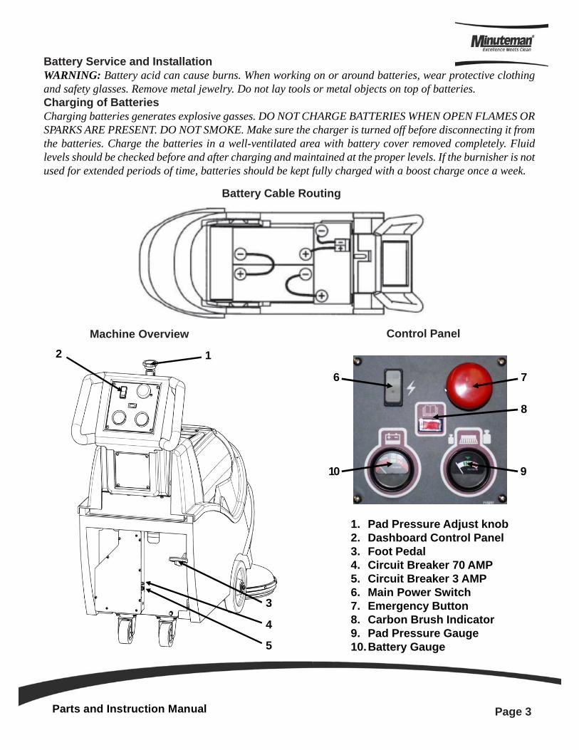
Battery Cable Routing
Machine Overview Control Panel
1. Pad Pressure Adjust knob2. Dashboard Control Panel3. Foot Pedal4. Circuit Breaker 70 AMP5. Circuit Breaker 3 AMP6. Main Power Switch7. Emergency Button8. Carbon Brush Indicator9. Pad Pressure Gauge10.Battery Gauge
3
4
5
12
7
8
6
910
Parts and Instruction Manual
Page 4
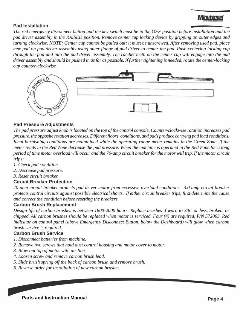
Pad InstallationThe red emergency disconnect button and the key switch must be in the OFF position before installation and thepad driver assembly in the RAISED position. Remove center cup locking device by gripping on outer edges andturning clockwise. NOTE: Center cup cannot be pulled out; it must be unscrewed. After removing used pad, placenew pad on pad driver assembly using outer flange of pad driver to center the pad. Push centering locking cupthrough the pad and into the pad driver assembly. The ratchet teeth on the center cup will engage into the paddriver assembly and should be pushed in as far as possible. If further tightening is needed, rotate the center-lockingcup counter-clockwise
Pad Pressure AdjustmentsThe pad pressure adjust knob is located on the top of the control console. Counter-clockwise rotation increases padpressure, the opposite rotation decreases. Different floors, conditions, and pads produce carrying pad load conditions.Ideal burnishing conditions are maintained while the operating range meter remains in the Green Zone. If themeter reads in the Red Zone decrease the pad pressure. When the machine is operated in the Red Zone for a longperiod of time motor overload will occur and the 70-amp circuit breaker for the motor will trip. If the motor circuittrips:1. Check pad condition.2. Decrease pad pressure.3. Reset circuit breaker.Circuit Breaker Protection70 amp circuit breaker protects pad driver motor from excessive overload conditions. 3.0 amp circuit breakerprotects control circuits against possible electrical shorts. If either circuit breaker trips, first determine the causeand correct the condition before resetting the breakers.Carbon Brush ReplacementDesign life of carbon brushes is between 1800-2000 hours. Replace brushes if worn to 3/8" or less, broken, orchipped. All carbon brushes should be replaced when motor is serviced. Four (4) are required, P/N 572003. Redindicator on control panel (above Emergency Disconnect Button, below the Dashboard) will glow when carbonbrush service is required.Carbon Brush Service1. Disconnect batteries from machine.2. Remove two screws that hold dust control housing and motor cover to motor.3. Blow out top of motor with air line.4. Loosen screw and remove carbon brush lead.5. Slide brush spring off the back of carbon brush and remove brush.6. Reverse order for installation of new carbon brushes.
Parts and Instruction Manual
Page 5
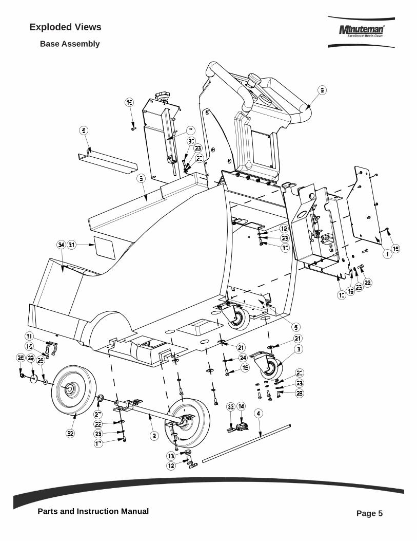
Exploded ViewsBase Assembly
Parts and Instruction Manual
Page 6
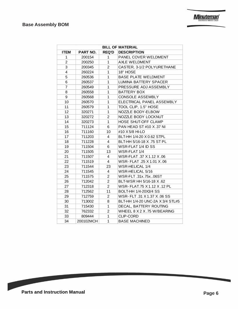
ITEM PART NO. REQ'D DESCRIPTION1 200154 1 PANEL COVER WELDMENT2 200250 1 AXLE WELDMENT3 200345 2 CASTER, 3-1/2 POLYURETHANE4 260224 1 18" HOSE5 260536 1 BASE PLATE WELDMENT6 260537 1 LUMINA BATTERY SPACER7 260549 1 PRESSURE ADJ ASSEMBLY8 260558 1 BATTERY BOX9 260568 1 CONSOLE ASSEMBLY10 260570 1 ELECTRICAL PANEL ASSEMBLY11 260579 1 TOOL CLIP, 1.5" HOSE12 320271 1 NOZZLE BODY-ELBOW13 320272 2 NOZZLE BODY LOCKNUT14 320273 1 HOSE SHUT-OFF CLAMP15 711124 6 PAN HEAD ST #10 X .37 NI16 711160 10 #10 X 5/8 HI-LO17 711203 4 BLT-HH 1/4-20 X 0.62 STPL18 711228 4 BLT-HH 5/16-18 X .75 ST PL19 711504 6 WSR-FLAT 1/4 ID SS20 711505 13 WSR-FLAT 1/421 711507 4 WSR-FLAT .37 X 1.12 X .0622 711519 4 WSR- FLAT .25 X 1.01 X .0623 711544 23 WSR-HELICAL 1/424 711545 4 WSR-HELICAL 5/1625 711575 2 WSR-FLT .31x.75x..06ST26 712042 2 BLT-WSR HH 5/16-18 X .6227 712318 2 WSR- FLAT.75 X 1.12 X .12 PL28 712562 11 BOLT-HH 1/4-20X3/4 SS29 712759 2 WSR- FLT .31 X 1.37 X .06 SS30 713002 8 BLT-HH 1/4-20 UNC-2A X 3/4 STL#531 715430 1 DECAL, BATTERY ROUTING32 762332 2 WHEEL 8 X 2 X .75 W/BEARING33 809444 1 CLIP-CORD34 200102MCH 1 BASE MACHINED
BILL OF MATERIAL
Base Assembly BOM
Parts and Instruction Manual
Page 7
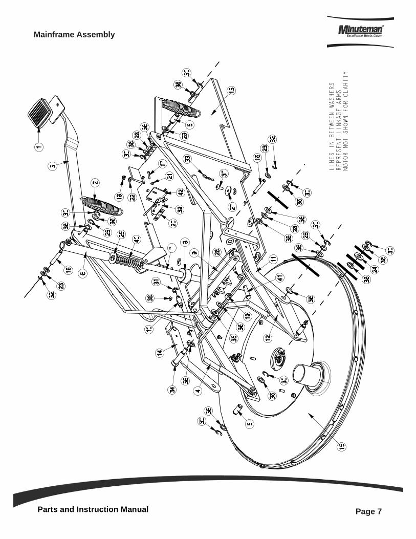
Mainframe Assembly
Parts and Instruction Manual
Page 8
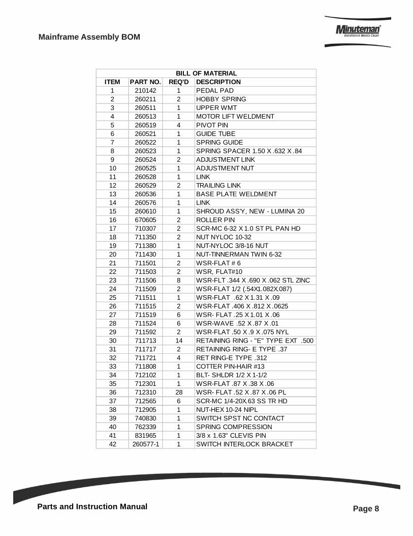
Mainframe Assembly BOM
ITEM PART NO. REQ'D DESCRIPTION1 210142 1 PEDAL PAD2 260211 2 HOBBY SPRING3 260511 1 UPPER WMT4 260513 1 MOTOR LIFT WELDMENT5 260519 4 PIVOT PIN6 260521 1 GUIDE TUBE7 260522 1 SPRING GUIDE8 260523 1 SPRING SPACER 1.50 X .632 X .849 260524 2 ADJUSTMENT LINK10 260525 1 ADJUSTMENT NUT11 260528 1 LINK12 260529 2 TRAILING LINK13 260536 1 BASE PLATE WELDMENT14 260576 1 LINK15 260610 1 SHROUD ASS'Y, NEW - LUMINA 2016 670605 2 ROLLER PIN17 710307 2 SCR-MC 6-32 X 1.0 ST PL PAN HD18 711350 2 NUT NYLOC 10-3219 711380 1 NUT-NYLOC 3/8-16 NUT20 711430 1 NUT-TINNERMAN TWIN 6-3221 711501 2 WSR-FLAT # 622 711503 2 WSR, FLAT#1023 711506 8 WSR-FLT .344 X .690 X .062 STL ZINC24 711509 2 WSR-FLAT 1/2 (.54X1.082X.087)25 711511 1 WSR-FLAT .62 X 1.31 X .0926 711515 2 WSR-FLAT .406 X .812 X .062527 711519 6 WSR- FLAT .25 X 1.01 X .0628 711524 6 WSR-WAVE .52 X .87 X .0129 711592 2 WSR-FLAT .50 X .9 X .075 NYL30 711713 14 RETAINING RING - "E" TYPE EXT .50031 711717 2 RETAINING RING- E TYPE .3732 711721 4 RET RING-E TYPE .31233 711808 1 COTTER PIN-HAIR #1334 712102 1 BLT- SHLDR 1/2 X 1-1/235 712301 1 WSR-FLAT .87 X .38 X .0636 712310 28 WSR- FLAT .52 X .87 X .06 PL37 712565 6 SCR-MC 1/4-20X.63 SS TR HD38 712905 1 NUT-HEX 10-24 NIPL39 740830 1 SWITCH SPST NC CONTACT40 762339 1 SPRING COMPRESSION41 831965 1 3/8 x 1.63" CLEVIS PIN42 260577-1 1 SWITCH INTERLOCK BRACKET
BILL OF MATERIAL
Parts and Instruction Manual
Page 9
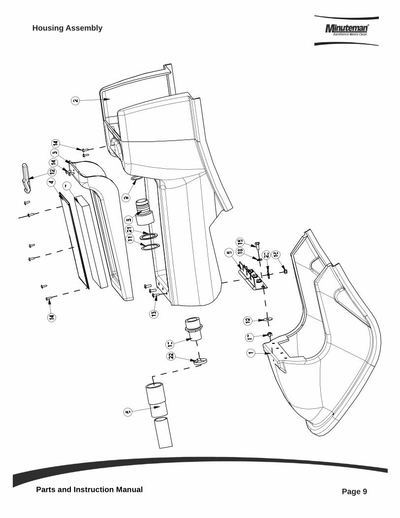
Housing Assembly
Parts and Instruction Manual
Page 10
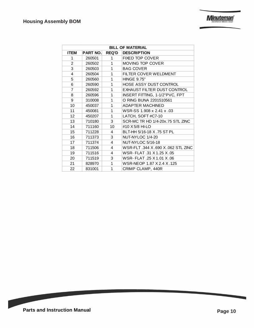
ITEM PART NO. REQ'D DESCRIPTION1 260501 1 FIXED TOP COVER2 260502 1 MOVING TOP COVER3 260503 1 BAG COVER4 260504 1 FILTER COVER WELDMENT5 260560 1 HINGE 9.75"6 260590 1 HOSE ASSY DUST CONTROL7 260592 1 EXHAUST FILTER DUST CONTROL8 260596 1 INSERT FITTING, 1-1/2"PVC, FPT9 310008 1 O RING BUNA 220151056110 450037 1 ADAPTER MACHINED11 450081 1 WSR-SS 1.908 x 2.41 x .0312 450207 1 LATCH, SOFT #C7-1013 710180 3 SCR-MC TR HD 1/4-20x.75 STL ZINC14 711160 10 #10 X 5/8 HI-LO15 711228 4 BLT-HH 5/16-18 X .75 ST PL16 711373 3 NUT-NYLOC 1/4-2017 711374 4 NUT-NYLOC 5/16-1818 711506 4 WSR-FLT .344 X .690 X .062 STL ZINC19 711516 4 WSR- FLAT .31 X 1.25 X .0520 711519 3 WSR- FLAT .25 X 1.01 X .0621 828970 1 WSR-NEOP 1.87 X 2.4 X .12522 831001 1 CRIMP CLAMP, 440R
BILL OF MATERIAL
Housing Assembly BOM
Parts and Instruction Manual
Page 11
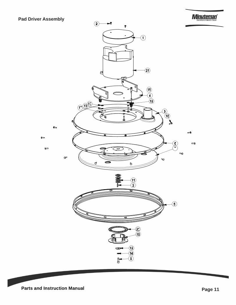
Pad Driver Assembly
Parts and Instruction Manual
Page 12
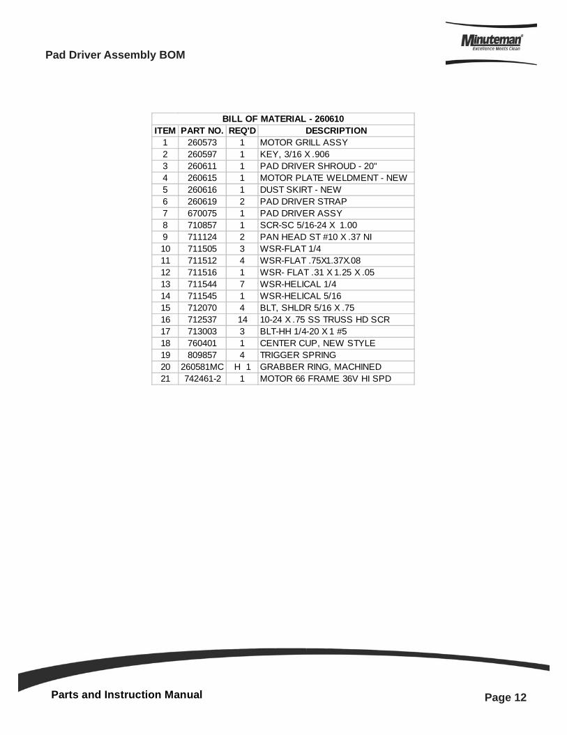
ITEM PART NO. REQ'D DESCRIPTION1 260573 1 MOTOR GRILL ASSY2 260597 1 KEY, 3/16 X .9063 260611 1 PAD DRIVER SHROUD - 20"4 260615 1 MOTOR PLATE WELDMENT - NEW5 260616 1 DUST SKIRT - NEW6 260619 2 PAD DRIVER STRAP7 670075 1 PAD DRIVER ASSY8 710857 1 SCR-SC 5/16-24 X 1.009 711124 2 PAN HEAD ST #10 X .37 NI10 711505 3 WSR-FLAT 1/411 711512 4 WSR-FLAT .75X1.37X.0812 711516 1 WSR- FLAT .31 X 1.25 X .0513 711544 7 WSR-HELICAL 1/414 711545 1 WSR-HELICAL 5/1615 712070 4 BLT, SHLDR 5/16 X .7516 712537 14 10-24 X .75 SS TRUSS HD SCR17 713003 3 BLT-HH 1/4-20 X 1 #518 760401 1 CENTER CUP, NEW STYLE19 809857 4 TRIGGER SPRING20 260581MC H 1 GRABBER RING, MACHINED21 742461-2 1 MOTOR 66 FRAME 36V HI SPD
BILL OF MATERIAL - 260610
Pad Driver Assembly BOM
Parts and Instruction Manual
Page 13
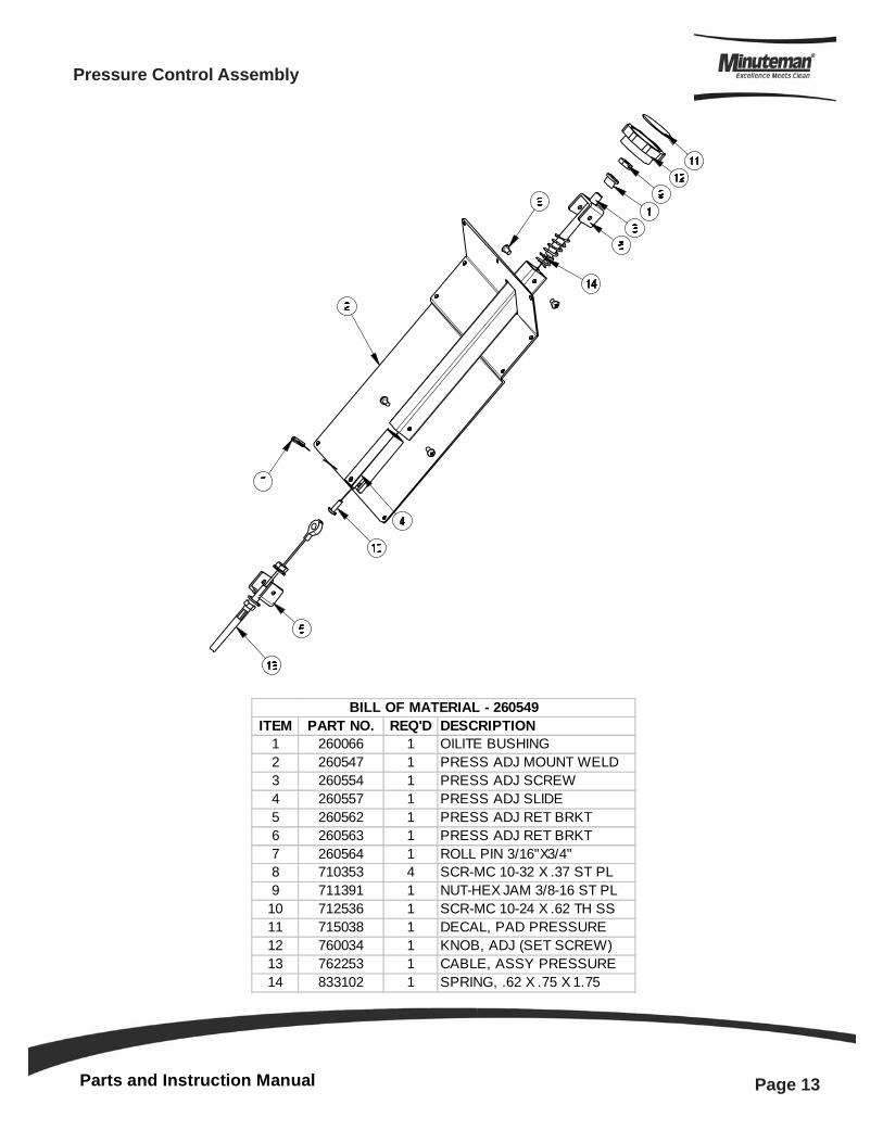
Pressure Control Assembly
ITEM PART NO. REQ'D DESCRIPTION1 260066 1 OILITE BUSHING2 260547 1 PRESS ADJ MOUNT WELD3 260554 1 PRESS ADJ SCREW4 260557 1 PRESS ADJ SLIDE5 260562 1 PRESS ADJ RET BRKT6 260563 1 PRESS ADJ RET BRKT7 260564 1 ROLL PIN 3/16"X3/4"8 710353 4 SCR-MC 10-32 X .37 ST PL9 711391 1 NUT-HEX JAM 3/8-16 ST PL
10 712536 1 SCR-MC 10-24 X .62 TH SS11 715038 1 DECAL, PAD PRESSURE12 760034 1 KNOB, ADJ (SET SCREW)13 762253 1 CABLE, ASSY PRESSURE14 833102 1 SPRING, .62 X .75 X 1.75
BILL OF MATERIAL - 260549
Parts and Instruction Manual
Page 14
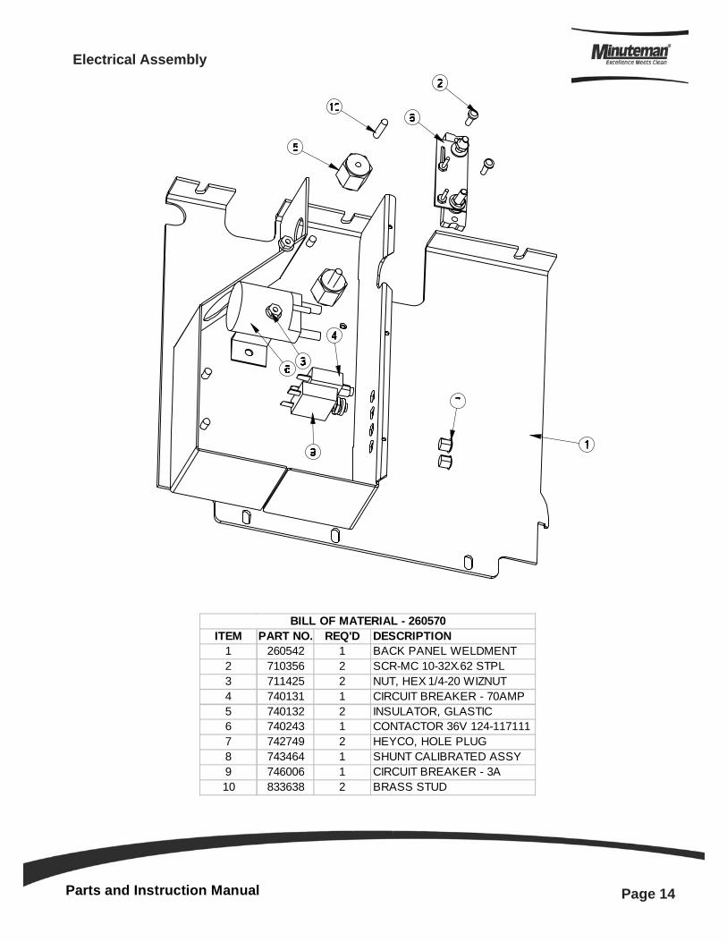
Electrical Assembly
ITEM PART NO. REQ'D DESCRIPTION1 260542 1 BACK PANEL WELDMENT2 710356 2 SCR-MC 10-32X.62 STPL3 711425 2 NUT, HEX 1/4-20 WIZNUT4 740131 1 CIRCUIT BREAKER - 70AMP5 740132 2 INSULATOR, GLASTIC6 740243 1 CONTACTOR 36V 124-1171117 742749 2 HEYCO, HOLE PLUG8 743464 1 SHUNT CALIBRATED ASSY9 746006 1 CIRCUIT BREAKER - 3A10 833638 2 BRASS STUD
BILL OF MATERIAL - 260570
Parts and Instruction Manual
Page 15
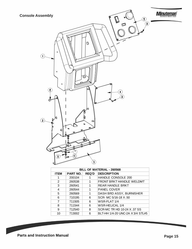
Console Assembly
ITEM PART NO. REQ'D DESCRIPTION1 200104 1 HANDLE CONSOLE 2002 260538 1 FRONT BRKT HANDLE WELDMT3 260541 1 REAR HANDLE BRKT4 260544 1 PANEL COVER5 260569 1 DASH BRD ASSY, BURNISHER6 710195 6 SCR- MC 5/16-18 X .507 711505 6 WSR-FLAT 1/48 711544 6 WSR-HELICAL 1/49 712540 8 SCR-MC TR HD 10-24 X .37 SS10 713002 6 BLT-HH 1/4-20 UNC-2A X 3/4 STL#5
BILL OF MATERIAL - 260568
Parts and Instruction Manual
Page 16
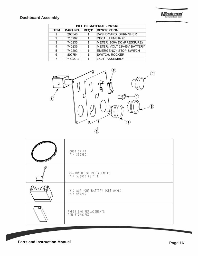
Dashboard Assembly
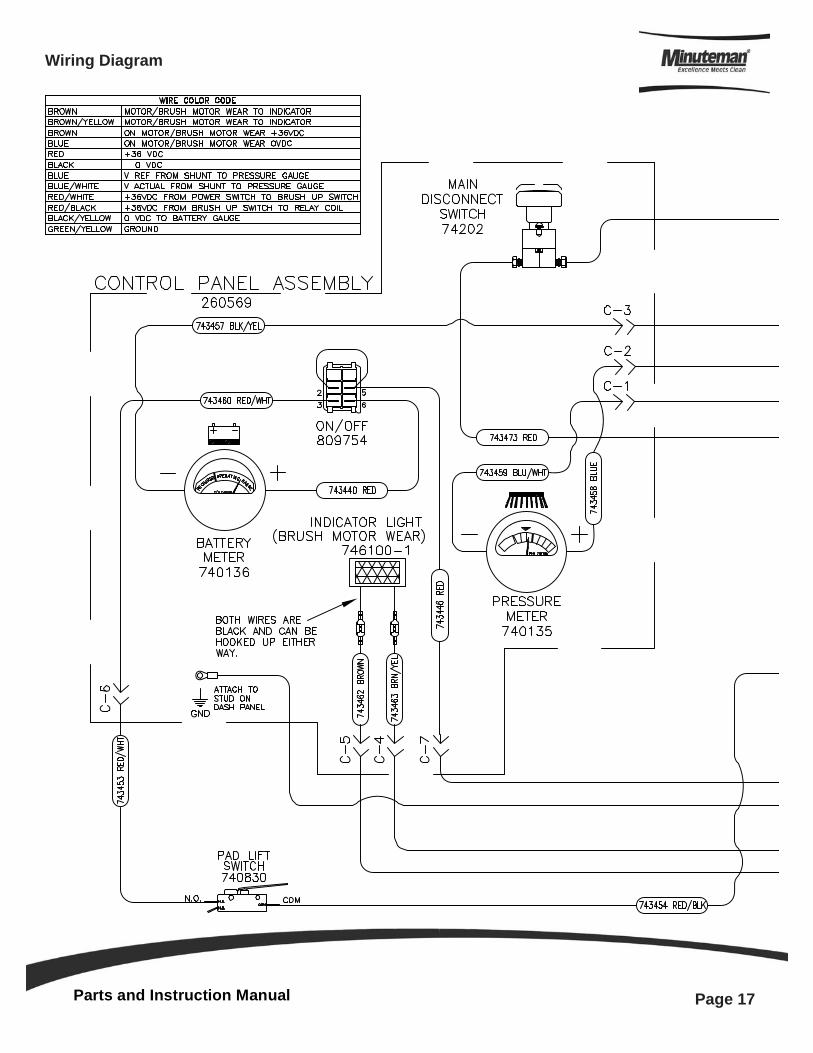
ITEM PART NO. REQ'D DESCRIPTION1 260546 1 DASHBOARD, BURNISHER2 715297 1 DECAL, LUMINA 203 740135 1 METER, 100A DC (PRESSURE)4 740136 1 METER, VOLT 22V45V BATTERY5 742202 1 EMERGENCY STOP SWITCH6 809754 1 SWITCH, ROCKER7 746100-1 1 LIGHT ASSEMBLY
BILL OF MATERIAL - 260569
Parts and Instruction Manual
Page 17
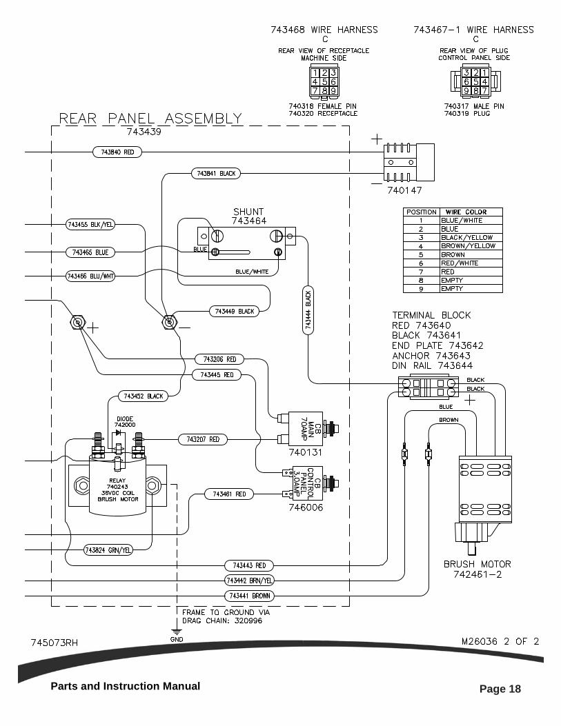
Wiring Diagram
Parts and Instruction Manual
Page 18
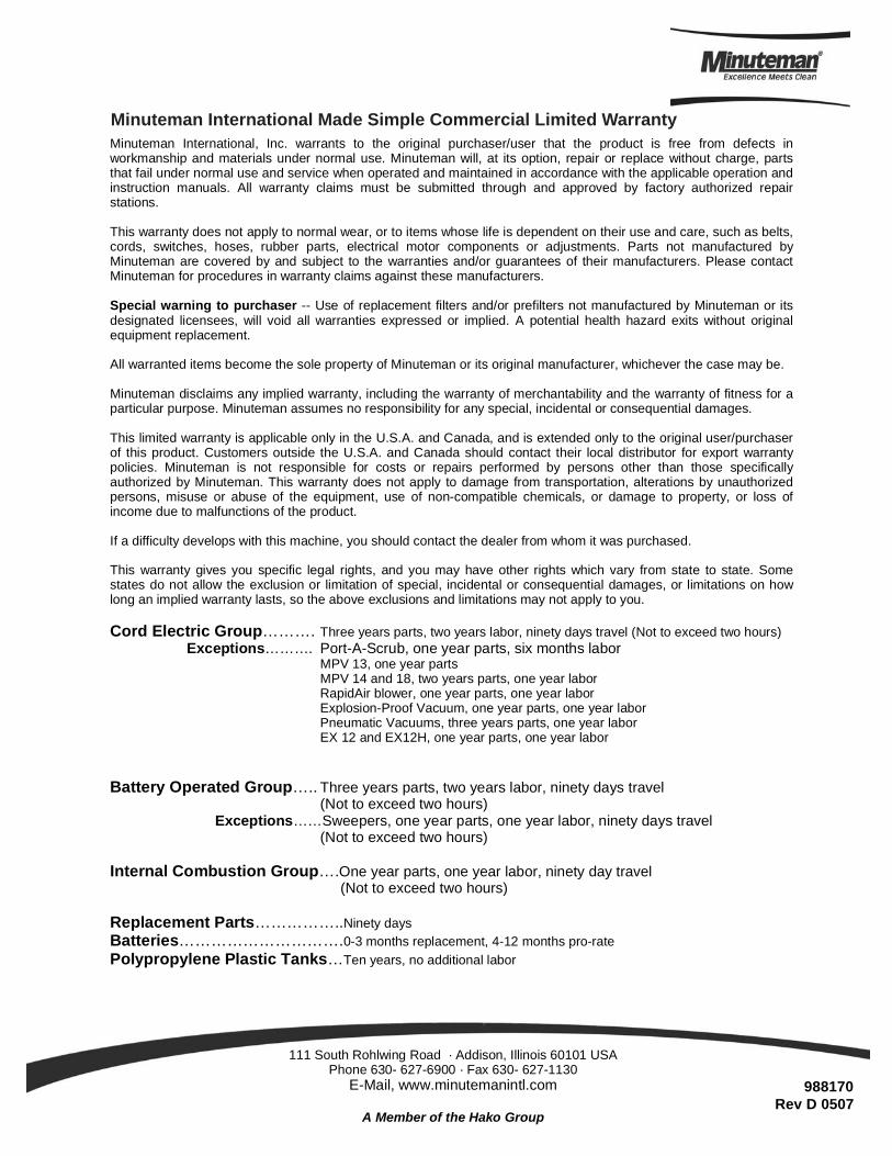
Minuteman International, Inc. warrants to the original purchaser/user that the product is free from defects in workmanship and materials under normal use. Minuteman will, at its option, repair or replace without charge, parts that fail under normal use and service when operated and maintained in accordance with the applicable operation and instruction manuals. All warranty claims must be submitted through and approved by factory authorized repair stations. This warranty does not apply to normal wear, or to items whose life is dependent on their use and care, such as belts, cords, switches, hoses, rubber parts, electrical motor components or adjustments. Parts not manufactured by Minuteman are covered by and subject to the warranties and/or guarantees of their manufacturers. Please contact Minuteman for procedures in warranty claims against these manufacturers. Special warning to purchaser -- Use of replacement filters and/or prefilters not manufactured by Minuteman or its designated licensees, will void all warranties expressed or implied. A potential health hazard exits without original equipment replacement. All warranted items become the sole property of Minuteman or its original manufacturer, whichever the case may be. Minuteman disclaims any implied warranty, including the warranty of merchantability and the warranty of fitness for a particular purpose. Minuteman assumes no responsibility for any special, incidental or consequential damages. This limited warranty is applicable only in the U.S.A. and Canada, and is extended only to the original user/purchaser of this product. Customers outside the U.S.A. and Canada should contact their local distributor for export warranty policies. Minuteman is not responsible for costs or repairs performed by persons other than those specifically authorized by Minuteman. This warranty does not apply to damage from transportation, alterations by unauthorized persons, misuse or abuse of the equipment, use of non-compatible chemicals, or damage to property, or loss of income due to malfunctions of the product. If a difficulty develops with this machine, you should contact the dealer from whom it was purchased. This warranty gives you specific legal rights, and you may have other rights which vary from state to state. Some states do not allow the exclusion or limitation of special, incidental or consequential damages, or limitations on how long an implied warranty lasts, so the above exclusions and limitations may not apply to you. Cord Electric Group………. Three years parts, two years labor, ninety days travel (Not to exceed two hours)
Exceptions………. Port-A-Scrub, one year parts, six months labor MPV 13, one year parts MPV 14 and 18, two years parts, one year labor RapidAir blower, one year parts, one year labor Explosion-Proof Vacuum, one year parts, one year labor Pneumatic Vacuums, three years parts, one year labor EX 12 and EX12H, one year parts, one year labor
Battery Operated Group….. Three years parts, two years labor, ninety days travel
(Not to exceed two hours) Exceptions……Sweepers, one year parts, one year labor, ninety days travel
(Not to exceed two hours) Internal Combustion Group….One year parts, one year labor, ninety day travel
(Not to exceed two hours) Replacement Parts……………..Ninety days Batteries………………………….0-3 months replacement, 4-12 months pro-rate Polypropylene Plastic Tanks…Ten years, no additional labor
111 South Rohlwing Road · Addison, Illinois 60101 USA Phone 630- 627-6900 · Fax 630- 627-1130
E-Mail, www.minutemanintl.com
A Member of the Hako Group
Minuteman International Made Simple Commercial Limited Warranty
988170Rev D 0507


![IS 11941 (1987): Hand Burnishers - Public.Resource.Org · IS 11941 (1987): Hand Burnishers [PGD 6: Earth, Metal And Wood Working Hand Tools] Title IS 11941 (1987): Hand Burnishers](https://img.pdfslide.net/doc/110x75/601805787a11da288e5c6f92/is-11941-1987-hand-burnishers-is-11941-1987-hand-burnishers-pgd-6-earth.jpg)