Embed Size (px)
Citation preview
PASSIVE DEVICESCATALOGUEEDITION 2.0
As a global partner of optical components, SENKO provides both standard and customized passive device products to the market. Our commitment to the stringent management of our supply chain and manufacturing partners enables us to consistently deliver the highest quality, lowest cost products to our customers.
SENKO offers an extensive range of product lines, including Fused Coupler, Filter-based WDM, Outside Plant use WDM, Polarization Maintaining Components, Switching and Routing, and other customized products are also available upon request.
SENKO works closely with the industry to constantly develop new products and techniques and makes customer satisfaction their top priority.
Senko’s quality system is certified to ISO 9001:2000 and all passive components are RoHS compliant.
pg. 04/09
pg. 10/14
pg. 15/22
pg. 23/27
pg. 28/33
pg. 34
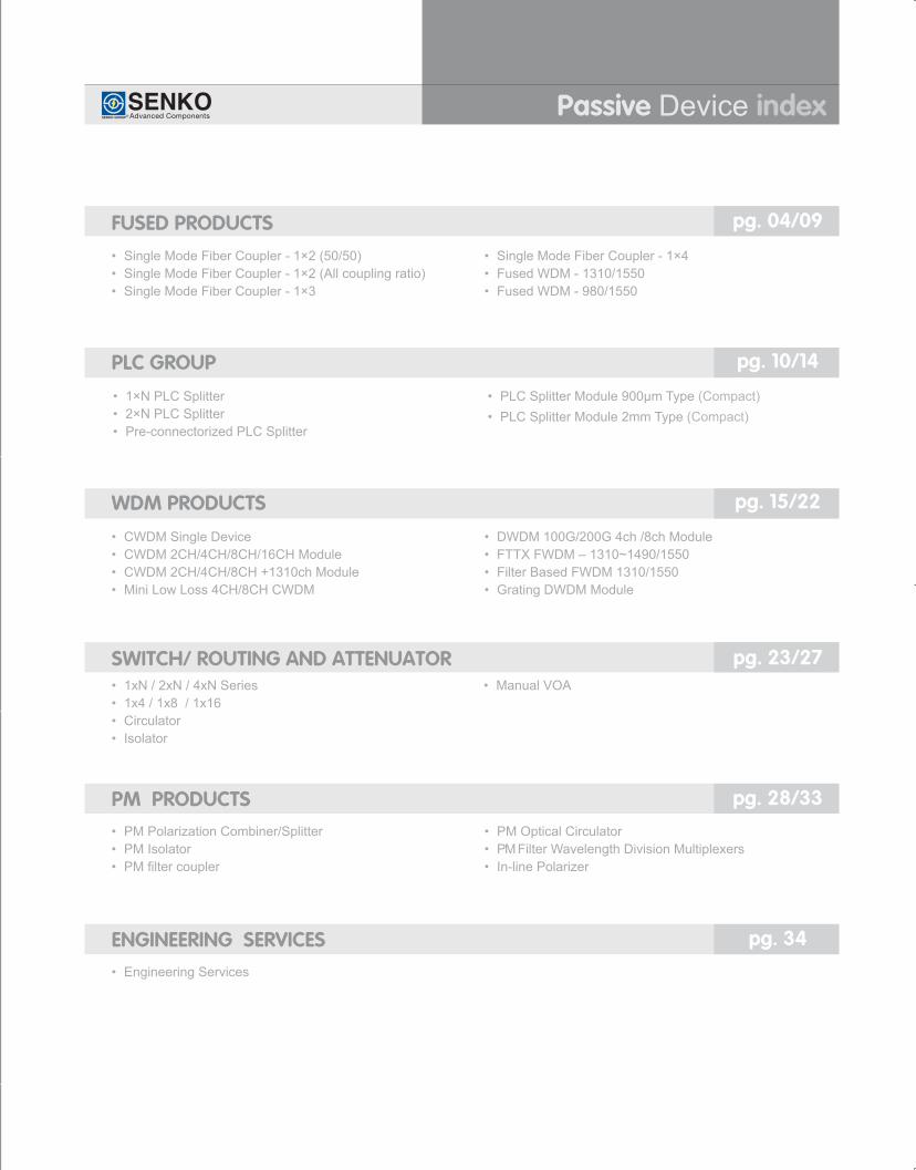
• SingleModeFiberCoupler-1×2(50/50)• SingleModeFiberCoupler-1×2(Allcouplingratio)• SingleModeFiberCoupler-1×3
• SingleModeFiberCoupler-1×4• FusedWDM-1310/1550• FusedWDM-980/1550
• 1×NPLCSplitter• 2×NPLCSplitter• Pre-connectorizedPLCSplitter
• PLCSplitterModule900µmType(Compact)• PLCSplitterModule2mmType(Compact)
• CWDMSingleDevice• CWDM2CH/4CH/8CH/16CHModule• CWDM2CH/4CH/8CH+1310chModule• MiniLowLoss4CH/8CHCWDM
• DWDM100G/200G4ch/8chModule• FTTXFWDM–1310~1490/1550• FilterBasedFWDM1310/1550• GratingDWDMModule
• 1xN/2xN/4xNSeries• 1x4/1x8/1x16• Circulator• Isolator
• ManualVOA
• PMPolarizationCombiner/Splitter• PMIsolator• PMfiltercoupler
• PMOpticalCirculator• PMFilterWavelengthDivisionMultiplexers• In-linePolarizer
• EngineeringServices
FUSED PRODUCTS
PLC GROUP
WDM PRODUCTS
SWITCH/ ROUTING AND ATTENUATOR
PM PRODUCTS
ENGINEERING SERVICES
Passive Device index
4
FUSE
D PRODUCTS
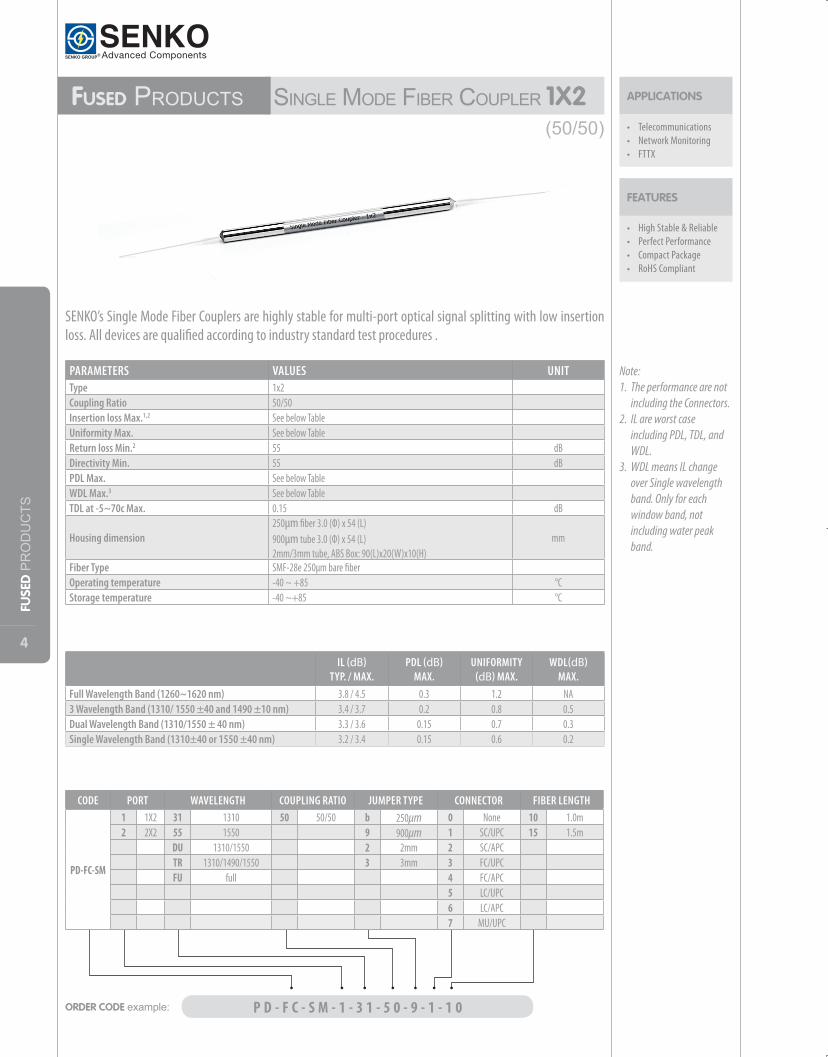
Fused Products SingleModeFiberCouPler 1X2
• High Stable & Reliable• Perfect Performance• Compact Package• RoHS Compliant
FEATURES
APPLICATIONS
• Telecommunications• Network Monitoring• FTTX
PARAMETERS VALUES UNITType 1x2Coupling Ratio 50/50Insertion loss Max.1,2 See below Table Uniformity Max. See below Table Return loss Min.2 55 dBDirectivity Min. 55 dBPDL Max. See below Table WDL Max.3 See below Table TDL at -5~70c Max. 0.15 dB
Housing dimension250µm fiber 3.0 (Ф) x 54 (L) 900µm tube 3.0 (Ф) x 54 (L)2mm/3mm tube, ABS Box: 90(L)x20(W)x10(H)
mm
Fiber Type SMF-28e 250µm bare fiberOperating temperature -40 ~ +85 °CStorage temperature -40 ~+85 °C
IL (dB)TYP. / MAX.
PDL (dB)MAX.
UNIFORMITY (dB) MAX.
WDL(dB)MAX.
Full Wavelength Band (1260~1620 nm) 3.8 / 4.5 0.3 1.2 NA3 Wavelength Band (1310/ 1550 ±40 and 1490 ±10 nm) 3.4 / 3.7 0.2 0.8 0.5 Dual Wavelength Band (1310/1550 ± 40 nm) 3.3 / 3.6 0.15 0.7 0.3Single Wavelength Band (1310±40 or 1550 ±40 nm) 3.2 / 3.4 0.15 0.6 0.2
Note: 1. The performance are not
including the Connectors.2. IL are worst case
including PDL, TDL, and WDL.
3. WDL means IL change over Single wavelength band. Only for each window band, not including water peak band.
SENKO’s Single Mode Fiber Couplers are highly stable for multi-port optical signal splitting with low insertion loss. All devices are qualified according to industry standard test procedures .
ORDER CODE example: P D - F C - S M - 1 - 3 1 - 5 0 - 9 - 1 - 1 0
CODE PORT WAVELENGTH COUPLING RATIO JUMPER TYPE CONNECTOR FIBER LENGTH
PD-FC-SM
1 1X2 31 1310 50 50/50 b 250µm 0 None 10 1.0m2 2X2 55 1550 9 900µm 1 SC/UPC 15 1.5m
DU 1310/1550 2 2mm 2 SC/APCTR 1310/1490/1550 3 3mm 3 FC/UPCFU full 4 FC/APC
5 LC/UPC6 LC/APC7 MU/UPC
(50/50)
5
FUSE
D PRODUCTS
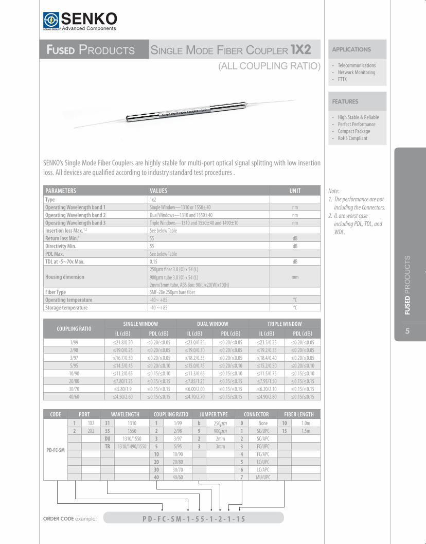
APPLICATIONS Fused Products SingleModeFiberCouPler 1X2
• High Stable & Reliable• Perfect Performance• Compact Package• RoHS Compliant
FEATURES
• Telecommunications• Network Monitoring• FTTX
PARAMETERS VALUES UNITType 1x2Operating Wavelength band 1 Single Window—1310 or 1550±40 nmOperating Wavelength band 2 Dual Windows—1310 and 1550±40 nmOperating Wavelength band 3 Triple Windows—1310 and 1550±40 and 1490±10 nmInsertion loss Max.1,2 See below Table Return loss Min.1 55 dBDirectivity Min. 55 dBPDL Max. See below Table TDL at -5~70c Max. 0.15 dB
Housing dimension250µm fiber 3.0 (Ф) x 54 (L) 900µm tube 3.0 (Ф) x 54 (L)2mm/3mm tube, ABS Box: 90(L)x20(W)x10(H)
mm
Fiber Type SMF-28e 250µm bare fiberOperating temperature -40~ +85 °CStorage temperature -40 ~+85 °C
Note: 1. The performance are not
including the Connectors.2. IL are worst case
including PDL, TDL, and WDL.
SENKO’s Single Mode Fiber Couplers are highly stable for multi-port optical signal splitting with low insertion loss. All devices are qualified according to industry standard test procedures .
COUPLING RATIOSINGLE WINDOW DUAL WINDOW TRIPLE WINDOW
IL (dB) PDL (dB) IL (dB) PDL (dB) IL (dB) PDL (dB)1/99 ≤21.8/0.20 ≤0.20/≤0.05 ≤23.0/0.25 ≤0.20/≤0.05 ≤23.5/0.25 ≤0.20/≤0.05 2/98 ≤19.0/0.25 ≤0.20/≤0.05 ≤19.0/0.30 ≤0.20/≤0.05 ≤19.2/0.35 ≤0.20/≤0.05 3/97 ≤16.7/0.30 ≤0.20/≤0.05 ≤18.2/0.35 ≤0.20/≤0.05 ≤18.4/0.40 ≤0.20/≤0.05 5/95 ≤14.5/0.45 ≤0.20/≤0.10 ≤15.0/0.45 ≤0.20/≤0.10 ≤15.2/0.50 ≤0.20/≤0.10
10/90 ≤11.2/0.65 ≤0.15/≤0.10 ≤11.3/0.65 ≤0.15/≤0.10 ≤11.5/0.75 ≤0.15/≤0.10 20/80 ≤7.80/1.25 ≤0.15/≤0.15 ≤7.85/1.25 ≤0.15/≤0.15 ≤7.95/1.50 ≤0.15/≤0.15 30/70 ≤5.80/1.9 ≤0.15/≤0.15 ≤6.00/2.00 ≤0.15/≤0.15 ≤6.20/2.10 ≤0.15/≤0.15 40/60 ≤4.50/2.60 ≤0.15/≤0.15 ≤4.70/2.70 ≤0.15/≤0.15 ≤4.90/2.80 ≤0.15/≤0.15
ORDER CODE example: P D - F C - S M - 1 - 5 5 - 1 - 2 - 1 - 1 5
CODE PORT WAVELENGTH COUPLING RATIO JUMPER TYPE CONNECTOR FIBER LENGTH
PD-FC-SM
1 1X2 31 1310 1 1/99 b 250µm 0 None 10 1.0m2 2X2 55 1550 2 2/98 9 900µm 1 SC/UPC 15 1.5m
DU 1310/1550 3 3/97 2 2mm 2 SC/APCTR 1310/1490/1550 5 5/95 3 3mm 3 FC/UPC
10 10/90 4 FC/APC20 20/80 5 LC/UPC30 30/70 6 LC/APC40 40/60 7 MU/UPC
(ALLCOUPLINGRATIO)
6
FUSE
D PRODUCTS
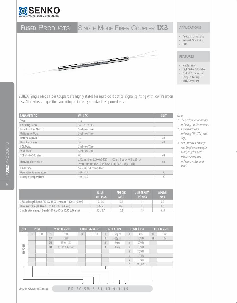
Fused Products SingleModeFiberCouPler1X3
• Single Fusion • High Stable & Reliable• Perfect Performance• Compact Package• RoHS Compliant
FEATURES
APPLICATIONS
• Telecommunications• Network Monitoring• FTTX
PARAMETERS VALUES UNITType 1x3Coupling Ratio 33.3/ 33.3/ 33.3Insertion loss Max.1,2 See below Table Uniformity Max. See below Table Return loss Min.1 55 dBDirectivity Min. 55 dBPDL Max. See below Table WDL Max.3 See below Table TDL at -5~70c Max. 0.3 dB
Housing dimension250µm fiber:3.0(Ф)x54(L) 900µm fiber:4.0(Ф)x60(L)2mm/3mm tube , ABS box: 100(L)x80(W)x10(H)
mm
Fiber Type SMF-28e 250µm bare fiber Operating temperature -40~+85 °CStorage temperature -40~+85 °C
IL (dB)TYP. / MAX.
PDL (dB)MAX.
UNIFORMITY (dB) MAX.
WDL(dB)MAX.
3 Wavelength Band (1310/ 1550 ±40 and 1490 ±10 nm) 6 / 6.6 0.3 1.4 0.5Dual Wavelength Band (1310/1550 ±40 nm) 5.8 / 6.2 0.25 1.2 0.3Single Wavelength Band (1310 ±40 or 1550 ±40 nm) 5.3 / 5.7 0.2 1.0 0.25
Note: 1. The performance are not
including the Connectors.2. IL are worst case
including PDL, TDL, and WDL.
3. WDL means IL change over Single wavelength band, only for each window band, not including water peak band.
SENKO’s Single Mode Fiber Couplers are highly stable for multi-port optical signal splitting with low insertion loss. All devices are qualified according to industry standard test procedures .
ORDER CODE example: P D - F C - S M - 3 - 3 1 - 3 3 - 9 - 1 - 1 5
CODE PORT WAVELENGTH COUPLING RATIO JUMPER TYPE CONNECTOR FIBER LENGTH
PD-FC
-SM
3 1X3 31 1310 33 33/33/33 b 250µm 0 None 10 1.0m55 1550 9 900µm 1 SC/UPC 15 1.5mDU 1310/1550 2 2mm 2 SC/APCTR 1310/1490/1550 3 3mm 3 FC/UPC
4 FC/APC5 LC/UPC6 LC/APC7 MU/UPC
7
FUSE
D PRODUCTS
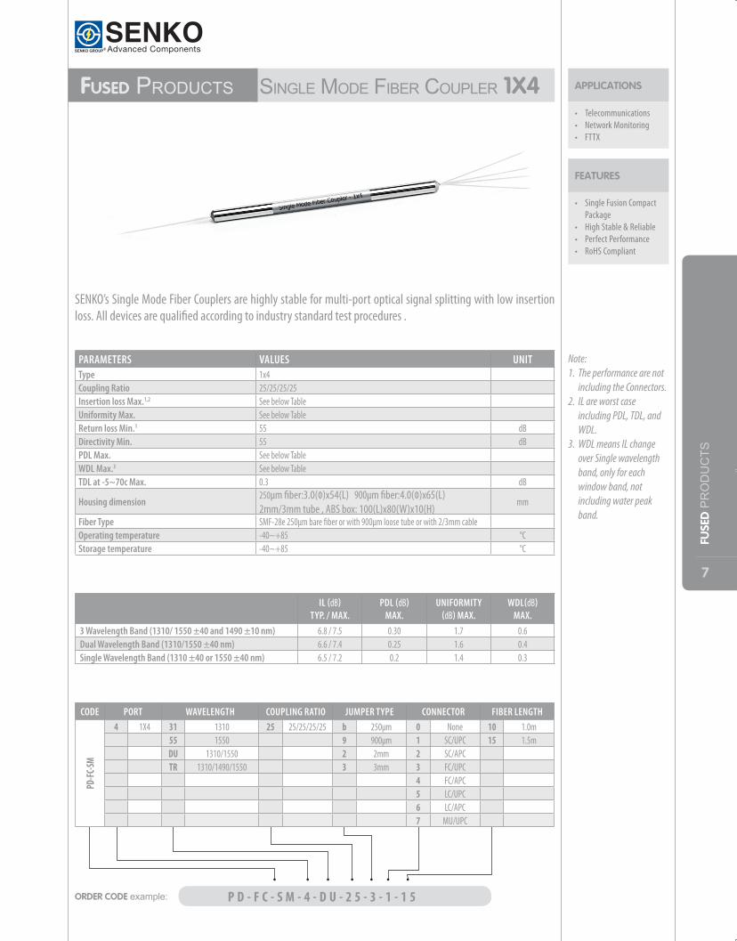
Fused Products SingleModeFiberCouPler1X4
• Single Fusion Compact Package
• High Stable & Reliable• Perfect Performance• RoHS Compliant
FEATURES
APPLICATIONS
• Telecommunications• Network Monitoring• FTTX
PARAMETERS VALUES UNITType 1x4Coupling Ratio 25/25/25/25Insertion loss Max.1,2 See below TableUniformity Max. See below Table Return loss Min.1 55 dBDirectivity Min. 55 dBPDL Max. See below Table WDL Max.3 See below TableTDL at -5~70c Max. 0.3 dB
Housing dimension250µm fiber:3.0(Ф)x54(L) 900µm fiber:4.0(Ф)x65(L)2mm/3mm tube , ABS box: 100(L)x80(W)x10(H)
mm
Fiber Type SMF-28e 250µm bare fiber or with 900µm loose tube or with 2/3mm cableOperating temperature -40~+85 °CStorage temperature -40~+85 °C
Note: 1. The performance are not
including the Connectors.2. IL are worst case
including PDL, TDL, and WDL.
3. WDL means IL change over Single wavelength band, only for each window band, not including water peak band.
SENKO’s Single Mode Fiber Couplers are highly stable for multi-port optical signal splitting with low insertion loss. All devices are qualified according to industry standard test procedures .
IL (dB)TYP. / MAX.
PDL (dB)MAX.
UNIFORMITY (dB) MAX.
WDL(dB)MAX.
3 Wavelength Band (1310/ 1550 ±40 and 1490 ±10 nm) 6.8 / 7.5 0.30 1.7 0.6 Dual Wavelength Band (1310/1550 ±40 nm) 6.6 / 7.4 0.25 1.6 0.4Single Wavelength Band (1310 ±40 or 1550 ±40 nm) 6.5 / 7.2 0.2 1.4 0.3
ORDER CODE example: P D - F C - S M - 4 - D U - 2 5 - 3 - 1 - 1 5
CODE PORT WAVELENGTH COUPLING RATIO JUMPER TYPE CONNECTOR FIBER LENGTH
PD-FC
-SM
4 1X4 31 1310 25 25/25/25/25 b 250µm 0 None 10 1.0m55 1550 9 900µm 1 SC/UPC 15 1.5mDU 1310/1550 2 2mm 2 SC/APCTR 1310/1490/1550 3 3mm 3 FC/UPC
4 FC/APC5 LC/UPC6 LC/APC7 MU/UPC
8
FUSE
D PRODUCTS
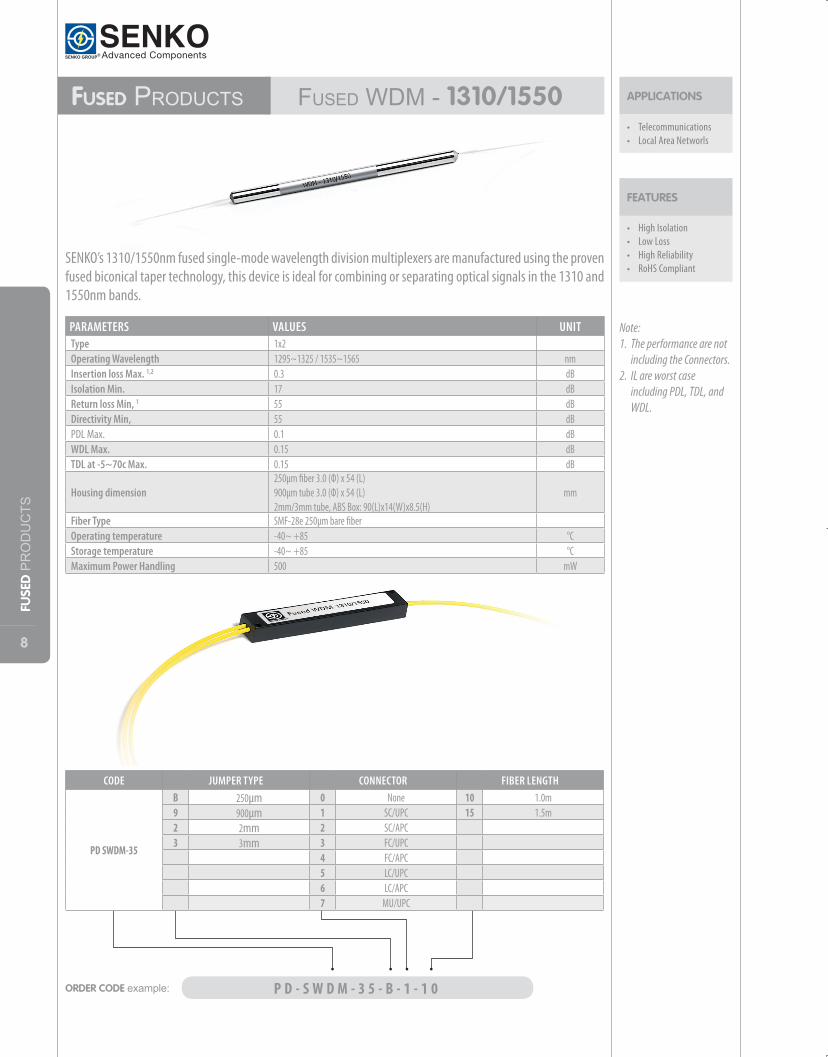
Fused Products FuSedWdM-1310/1550
• High Isolation• Low Loss• High Reliability• RoHS Compliant
FEATURES
APPLICATIONS
• Telecommunications• Local Area Networls
PARAMETERS VALUES UNITType 1x2Operating Wavelength 1295~1325 / 1535~1565 nmInsertion loss Max. 1,2 0.3 dBIsolation Min. 17 dBReturn loss Min, 1 55 dBDirectivity Min, 55 dBPDL Max. 0.1 dBWDL Max. 0.15 dBTDL at -5~70c Max. 0.15 dB
Housing dimension250μm fiber 3.0 (Ф) x 54 (L) 900μm tube 3.0 (Ф) x 54 (L) 2mm/3mm tube, ABS Box: 90(L)x14(W)x8.5(H)
mm
Fiber Type SMF-28e 250μm bare fiberOperating temperature -40~ +85 °CStorage temperature -40~ +85 °CMaximum Power Handling 500 mW
SENKO’s 1310/1550nm fused single-mode wavelength division multiplexers are manufactured using the proven fused biconical taper technology, this device is ideal for combining or separating optical signals in the 1310 and 1550nm bands.
ORDER CODE example: P D - S W D M - 3 5 - B - 1 - 1 0
CODE JUMPER TYPE CONNECTOR FIBER LENGTH
PD SWDM-35
B 250µm 0 None 10 1.0m9 900µm 1 SC/UPC 15 1.5m2 2mm 2 SC/APC3 3mm 3 FC/UPC
4 FC/APC5 LC/UPC6 LC/APC7 MU/UPC
Note: 1. The performance are not
including the Connectors.2. IL are worst case
including PDL, TDL, and WDL.
9
FUSE
D PRODUCTS
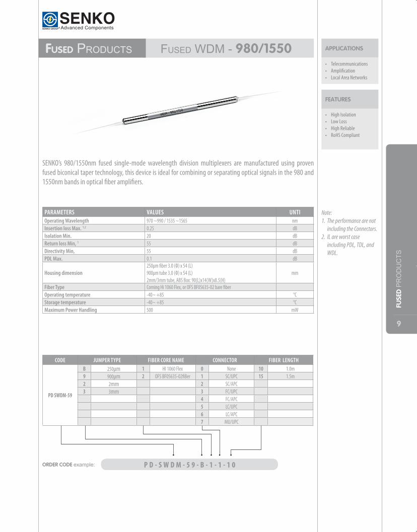
Fused Products FuSedWdM-980/1550
• High Isolation• Low Loss• High Reliable• RoHS Compliant
FEATURES
APPLICATIONS
• Telecommunications• Amplification• Local Area Networks
PARAMETERS VALUES UNTIOperating Wavelength 970 ~990 / 1535 ~1565 nmInsertion loss Max. 1,2 0.25 dBIsolation Min. 20 dBReturn loss Min, 1 55 dBDirectivity Min, 55 dBPDL Max. 0.1 dB
Housing dimension250μm fiber 3.0 (Ф) x 54 (L) 900μm tube 3.0 (Ф) x 54 (L) 2mm/3mm tube, ABS Box: 90(L)x14(W)x8.5(H)
mm
Fiber Type Corning Hi 1060 Flex, or OFS BF05635-02 bare fiberOperating temperature -40~ +85 °CStorage temperature -40~ +85 °CMaximum Power Handling 500 mW
SENKO’s 980/1550nm fused single-mode wavelength division multiplexers are manufactured using proven fused biconical taper technology, this device is ideal for combining or separating optical signals in the 980 and 1550nm bands in optical fiber amplifiers.
ORDER CODE example: P D - S W D M - 5 9 - B - 1 - 1 - 1 0
CODE JUMPER TYPE FIBER CORE NAME CONNECTOR FIBER LENGTH
PD SWDM-59
B 250µm 1 HI 1060 Flex 0 None 10 1.0m9 900µm 2 OFS BF05635-02fiBer 1 SC/UPC 15 1.5m2 2mm 2 SC/APC3 3mm 3 FC/UPC
4 FC/APC5 LC/UPC6 LC/APC7 MU/UPC
Note: 1. The performance are not
including the Connectors.2. IL are worst case
including PDL, TDL, and WDL.
10
PLC GROUP
PLC GrouP 1xN PlCSPlitter
• Low insertion loss; • High maximum power
tolerance; • Excellent splitting
uniformity; • Broadband Operating
wavelength; • Compact design;• Low polarization
dependency
FEATURES
• They are available in 1x4, 8, 16, 32 and 64 configurations, with various connector options.
• Custom packaging is also available
OPTIONS
APPLICATIONS
• Telecom, datacom• Local Area Networks
(LANs)• Cable TV (CATV)• Local Convergence
points (LCP)• FTTX
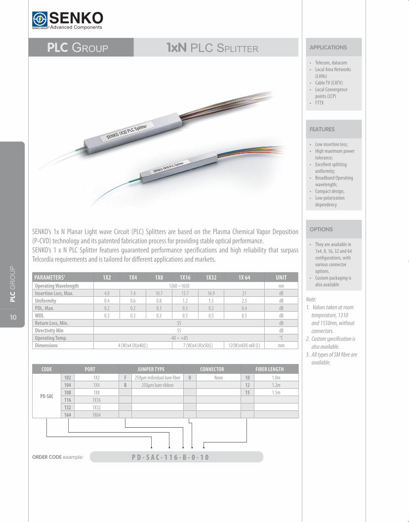
PARAMETERS1 1X2 1X4 1X8 1X16 1X32 1X 64 UNITOperating Wavelength 1260 ~1650 nmInsertion Loss, Max. 4.0 7.4 10.7 13.7 16.9 21 dBUniformity 0.4 0.6 0.8 1.2 1.5 2.5 dBPDL, Max. 0.2 0.2 0.3 0.3 0.3 0.4 dBWDL 0.3 0.3 0.3 0.5 0.5 0.5 dBReturn Loss, Min. 55 dBDirectivity Min 55 dBOperating Temp. -40 ~ +85 °CDimensions 4 (W)x4 (H)x40(L) 7 (W)x4 (H)x50(L) 12(W)x4(H) x60 (L) mm
Note: 1. Values taken at room
temperature, 1310 and 1550nm, without connectors.
2. Custom specification is also available.
3. All types of SM fibre are available.
ORDER CODE example: P D - S A C - 1 1 6 - B - 0 - 1 0
CODE PORT JUMPER TYPE CONNECTOR FIBER LENGTH
PD-SAC
102 1X2 F 250µm individual bare fiber 0 None 10 1.0m104 1X4 B 250µm bare ribbon 12 1.2m108 1X8 15 1.5m116 1X16132 1X32164 1X64
SENKO’s 1x N Planar Light wave Circuit (PLC) Splitters are based on the Plasma Chemical Vapor Deposition (P-CVD) technology and its patented fabrication process for providing stable optical performance. SENKO’s 1 x N PLC Splitter features guaranteed performance specifications and high reliability that surpass Telcordia requirements and is tailored for different applications and markets.
11
PLC GROUP
PLC GrouP 2xN PlCSPlitter
• Low insertion loss; • High maximum power
tolerance; • Excellent splitting
uniformity; • Broadband Operating
wavelength• Compact design;• Low polarization
dependency
FEATURES
They are available in 2x4, 8, 16, and 32 configurations, with various connector options.Custom packaging is also available
OPTIONS
APPLICATIONS
• Telecom, datacom• Local Area Networks
(LANs)• Cable TV (CATV)• Local Convergence
points (LCP)• FTTX
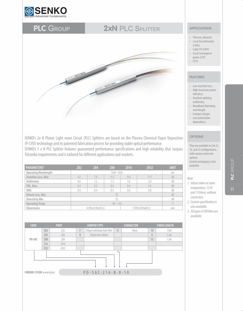
PARAMETERS1 2X2 2X4 2X8 2X16 2X32 UNITOperating Wavelength 1260~1650 nmInsertion Loss, Max. 4.2 7.8 11.5 14.5 17.7 dBUniformity 0.6 1.2 1.5 1.8 2.0 dBPDL, Max. 0.2 0.2 0.4 0.4 0.4 dBWDL 0.4 0.4 0.5 0.6 0.8 dBReturn Loss, Min. 55 dBDirectivity Min 55 dBOperating Temp. -40~ +85 °CDimensions 4 (W)x4 (H)x50 (L) 7 (W)x4 (H)x60 (L) mm
Note: 1. Values taken at room
temperature, 1310 and 1550nm, without connectors.
2. Custom specification is also available.
3. All types of SM fibre are available.
SENKO’s 2x N Planar Light wave Circuit (PLC) Splitters are based on the Plasma Chemical Vapor Deposition (P-CVD) technology and its patented fabrication process for providing stable optical performance. SENKO’s 1 x N PLC Splitter features guaranteed performance specifications and high reliability that surpass Telcordia requirements and is tailored for different applications and markets.
ORDER CODE example: P D - S A C - 2 1 6 - B - 0 - 1 0
CODE PORT JUMPER TYPE CONNECTOR FIBER LENGTH
PD-SAC
202 2X2 F 250µm individual bare fiber 0 None 10 1.0m204 2X4 B 250µm bare ribbon 12 1.2m208 2X8 15 1.5m216 2X16232 2X32
12
PLC GROUP
PLC grouP Pre-connectorized PlCSPlitter
• Low insertion loss; • High maximum power
tolerance; • Excellent splitting
uniformity; • Broadband Operating
wavelength; • Compact design;• Low polarization
dependency
FEATURES
• They are available in 1x4, 8, 16, 32and64 configurations, with various connector options.
• Custom packaging is also available
OPTIONS
APPLICATIONS
• Telecom, datacom• Local Area Networks
(LANs)• Cable TV (CATV)• Local Convergence
points (LCP)• FTTX
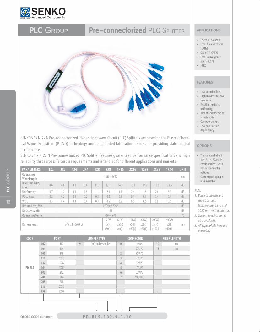
PARAMETERS1 1X2 2X2 1X4 2X4 1X8 2X8 1X16 2X16 1X32 2X32 1X64 UNITOperating Wavelength
1260 ~1650 nm
Insertion Loss, Max.
4.6 4.8 8.0 8.4 11.3 12.1 14.3 15.1 17.5 18.3 21.6 dB
Uniformity 0.7 1.2 0.9 1.8 1.1 2.1 1.5 2.4 1.8 2.6 3.1 dBPDL, Max. 0.2 0.2 0.2 0.2 0.3 0.4 0.3 0.4 0.3 0.4 0.4 dBWDL 0.3 0.4 0.3 0.4 0.3 0.5 0.5 0.6 0.5 0.8 0.5 dBReturn Loss, Min. UPC:50,APC:55 dBDirectivity Min 55 dBOperating Temp. -30 ~ +70 °C
Dimensions 7(W)x4(H)x60(L)12(W)x5(H)x80(L)
12(W)x5(H)x60(L)
12(W)x5(H)x80(L)
20(W)x6(H)x80(L)
20(W)x6(H)x100(L)
40(W)x6(H)
x100(L)mm
Note: 1. Value of parameters
shows at room temperature, 1310 and 1550 nm ,with connector.
2. Custom specification is also available.
3. All types of SM fibre are available.
ORDER CODE example: P D - B L S - 1 0 2 - 9 - 1 - 1 0
CODE PORT JUMPER TYPE CONNECTOR FIBER LENGTH
PD-BLS
102 1X2 9 900µm loose tube 0 None 10 1.0m104 1X4 1 SC/UPC 15 1.5m108 1X8 2 SC/APC116 1X16 3 FC/UPC132 1X32 4 FC/APC164 1X64 5 LC/UPC202 2X2 6 LC/APC204 2X4 7 MU/UPC208 2X8216 2X16232 2X32
SENKO’s 1x N, 2x N Pre-connectorized Planar Light wave Circuit (PLC) Splitters are based on the Plasma Chem-ical Vapor Deposition (P-CVD) technology and its patented fabrication process for providing stable optical performance. SENKO’s 1 x N, 2x N Pre-connectorized PLC Splitter features guaranteed performance specifications and high reliability that surpass Telcordia requirements and is tailored for different applications and markets.
13
PLC GROUP
PLC GrouP PlCSPlitterModule900µmtyPe
• Compact package• Stable optical character• Broadband operating
wavelength• Low insertion loss• Low back reflection• Excellent output
uniformity
FEATURES
They are available in 1x4, 8, 16, and 32 configurations, with various connector options.2 x N series is available upon request. Custom packaging is also available
OPTIONS
APPLICATIONS
• Telecom, datacom• Local Area Networks
(LANs)• Cable TV (CATV)• Local Convergence
points (LCP)• FTTX
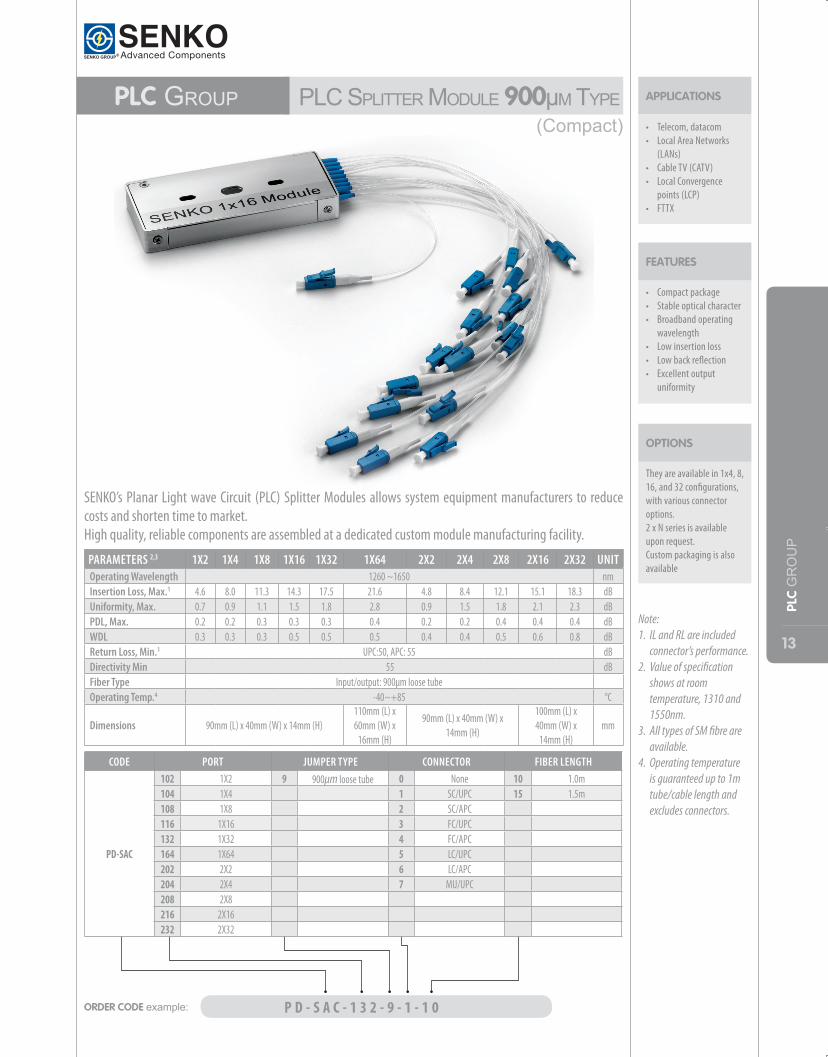
PARAMETERS 2,3 1X2 1X4 1X8 1X16 1X32 1X64 2X2 2X4 2X8 2X16 2X32 UNITOperating Wavelength 1260 ~1650 nmInsertion Loss, Max.1 4.6 8.0 11.3 14.3 17.5 21.6 4.8 8.4 12.1 15.1 18.3 dBUniformity, Max. 0.7 0.9 1.1 1.5 1.8 2.8 0.9 1.5 1.8 2.1 2.3 dBPDL, Max. 0.2 0.2 0.3 0.3 0.3 0.4 0.2 0.2 0.4 0.4 0.4 dBWDL 0.3 0.3 0.3 0.5 0.5 0.5 0.4 0.4 0.5 0.6 0.8 dBReturn Loss, Min.1 UPC:50, APC: 55 dBDirectivity Min 55 dBFiber Type Input/output: 900µm loose tubeOperating Temp.4 -40~+85 °C
Dimensions 90mm (L) x 40mm (W) x 14mm (H)110mm (L) x 60mm (W) x
16mm (H)
90mm (L) x 40mm (W) x 14mm (H)
100mm (L) x 40mm (W) x
14mm (H)mm
Note: 1. IL and RL are included
connector’s performance.2. Value of specification
shows at room temperature, 1310 and 1550nm.
3. All types of SM fibre are available.
4. Operating temperature is guaranteed up to 1m tube/cable length and excludes connectors.
ORDER CODE example: P D - S A C - 1 3 2 - 9 - 1 - 1 0
CODE PORT JUMPER TYPE CONNECTOR FIBER LENGTH
PD-SAC
102 1X2 9 900µm loose tube 0 None 10 1.0m104 1X4 1 SC/UPC 15 1.5m108 1X8 2 SC/APC116 1X16 3 FC/UPC132 1X32 4 FC/APC164 1X64 5 LC/UPC202 2X2 6 LC/APC204 2X4 7 MU/UPC208 2X8216 2X16232 2X32
(Compact)
SENKO’s Planar Light wave Circuit (PLC) Splitter Modules allows system equipment manufacturers to reduce costs and shorten time to market.High quality, reliable components are assembled at a dedicated custom module manufacturing facility.
14
PLC GROUP
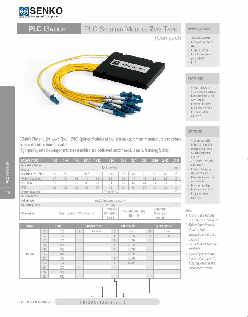
PLC GrouP PlCSPlitterModule2MMtyPe
• Compact package• Stable optical character• Broadband operating
wavelength• Low insertion loss• Low back reflection• Excellent output
uniformity
• They are available in 1x4 , 8.16 and 32 configurations with various connector options
• 2xN Series is available upon request
• Custom packaging is also available Broadband operating wavelength
• Low insertion loss• Low back reflection• Excellent output
uniformity
FEATURES
OPTIONS
APPLICATIONS
• Telecom, datacom• Local Area Networks
(LANs)• Cable TV (CATV)• Local Convergence
points (LCP)• FTTX
PARAMETERS 2,3 1X2 1X4 1X8 1X16 1X32 1X64 2X2 2X4 2X8 2X16 2X32 UNITOperating Wave-length
1260 nm ~1650 nm
Insertion Loss, Max.1 4.6 8.0 11.3 14.3 17.5 21.6 4.8 8.4 12.1 15.1 18.3 dBUniformity, Max. 0.7 0.9 1.1 1.5 1.8 2.8 0.9 1.5 1.8 2.1 2.3 dBPDL, Max. 0.2 0.2 0.3 0.3 0.3 0.4 0.2 0.2 0.4 0.4 0.4 dBWDL 0.3 0.3 0.3 0.5 0.5 0.5 0.4 0.4 0.5 0.6 0.8 dBReturn Loss, Min.1 UPC: 50, APC:55 dBDirectivity Min 55 dBCable Type Input/output:2mm/3mm CableOperating Temp.4 -40~+85 °C
Dimensions 100mm (L) x 80mm (W) x 10mm (H)120mm (L) x 90mm (W) x
15mm (H)
100mm (L) x 80mm (W) x 10mm (H)
120mm (L) x 80mm (W) x
10mm (H)
Note: 1. IL and RL are included
connector’s performance.2. Value of specification
shows at room temperature, 1310 and 1550nm.
3. All types of SM fibre are available.
4. Operating temperature is guaranteed up to 1m tube/cable length and excludes connectors.
SENKO’s Planar Light wave Circuit (PLC) Splitter Modules allows system equipment manufacturers to reduce costs and shorten time to market. High quality, reliable components are assembled at a dedicated custom module manufacturing facility.
ORDER CODE example: P D - S A C - 1 3 2 - 2 - 2 - 1 5
CODE PORT JUMPER TYPE CONNECTOR FIBER LENGTH
PD-SAC
102 1X2 2 2mm cable 0 None 10 1.0m104 1X4 1 SC/UPC 15 1.5m108 1X8 2 SC/APC116 1X16 3 FC/UPC132 1X32 4 FC/APC164 1X64 5 LC/UPC202 2X2 6 LC/APC204 2X4 7 MU/UPC208 2X8216 2X16232 2X32
(Compact)
15
WD
M PRODUCTS
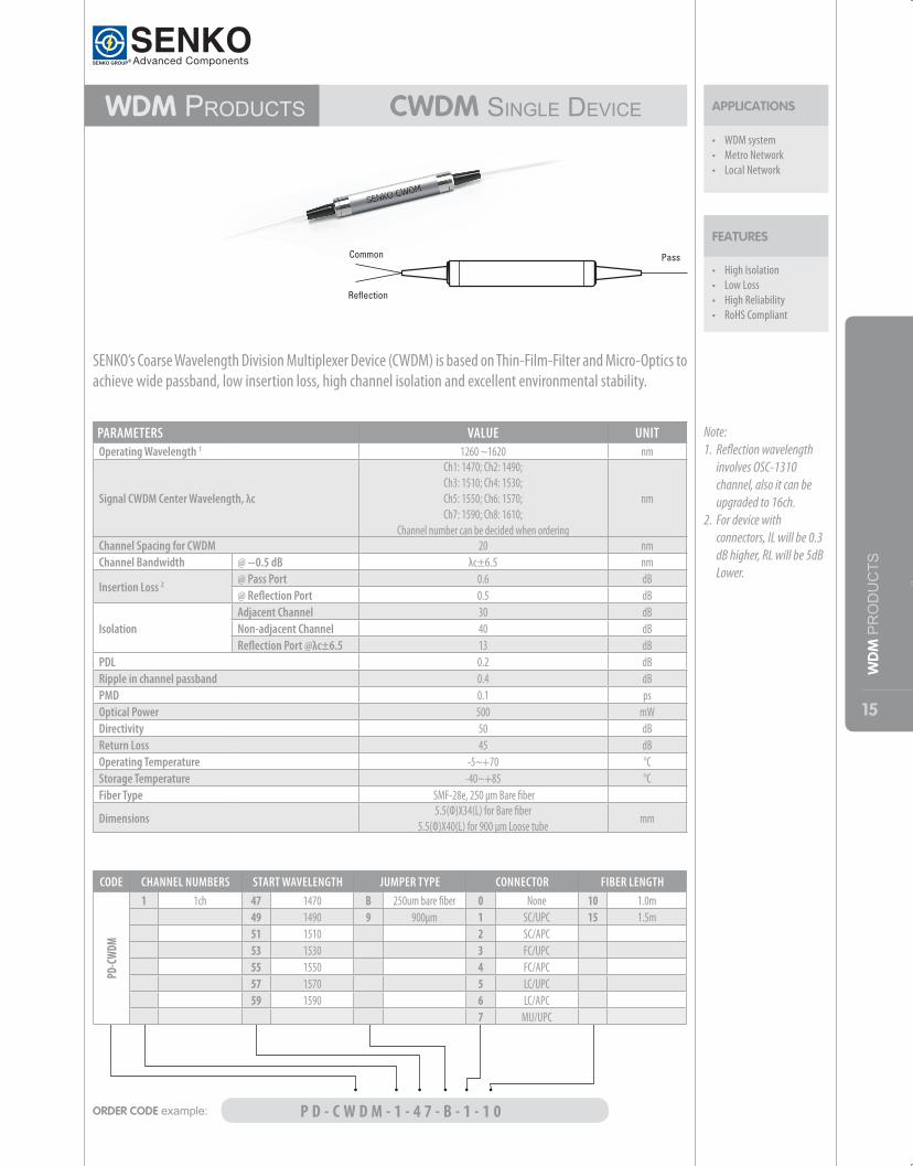
WdM Products CWDM SingledeviCe
• High Isolation• Low Loss• High Reliability• RoHS Compliant
FEATURES
APPLICATIONS
• WDM system• Metro Network• Local Network
PARAMETERS VALUE UNITOperating Wavelength 1 1260 ~1620 nm
Signal CWDM Center Wavelength, λc
Ch1: 1470; Ch2: 1490;Ch3: 1510; Ch4: 1530;Ch5: 1550; Ch6: 1570;Ch7: 1590; Ch8: 1610;
Channel number can be decided when ordering
nm
Channel Spacing for CWDM 20 nmChannel Bandwidth @ −0.5 dB λc±6.5 nm
Insertion Loss 2 @ Pass Port 0.6 dB@ Reflection Port 0.5 dB
IsolationAdjacent Channel 30 dBNon-adjacent Channel 40 dBReflection Port @λc±6.5 13 dB
PDL 0.2 dBRipple in channel passband 0.4 dBPMD 0.1 psOptical Power 500 mWDirectivity 50 dBReturn Loss 45 dBOperating Temperature -5~+70 °CStorage Temperature -40~+85 °CFiber Type SMF-28e, 250 μm Bare fiber
Dimensions5.5(Ф)X34(L) for Bare fiber
5.5(Ф)X40(L) for 900 μm Loose tubemm
Note: 1. Reflection wavelength
involves OSC-1310 channel, also it can be upgraded to 16ch.
2. For device with connectors, IL will be 0.3 dB higher, RL will be 5dB Lower.
SENKO’s Coarse Wavelength Division Multiplexer Device (CWDM) is based on Thin-Film-Filter and Micro-Optics to achieve wide passband, low insertion loss, high channel isolation and excellent environmental stability.
ORDER CODE example: P D - C W D M - 1 - 4 7 - B - 1 - 1 0
CODE CHANNEL NUMBERS START WAVELENGTH JUMPER TYPE CONNECTOR FIBER LENGTH
PD-C
WDM
1 1ch 47 1470 B 250um bare fiber 0 None 10 1.0m49 1490 9 900µm 1 SC/UPC 15 1.5m51 1510 2 SC/APC53 1530 3 FC/UPC55 1550 4 FC/APC57 1570 5 LC/UPC59 1590 6 LC/APC
7 MU/UPC
16
WD
M PRODUCTS
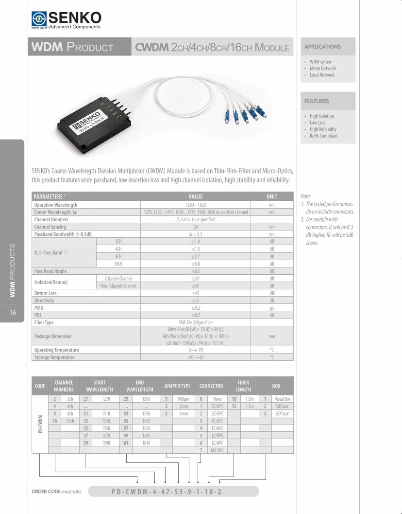
WdM ProduCtCWdM2Ch/4Ch/8Ch/16ChModule
• High Isolation• Low Loss• High Reliability• RoHS Compliant
FEATURES
APPLICATIONS
• WDM system• Metro Network• Local Network
PARAMETERS 1 VALUE UNITOperation Wavelength 1260 ~1620 nmCenter Wavelength, λc 1270, 1290... 1470, 1490... 1570, 1590, 1610 or specified channel nmChannel Numbers 2, 4 or 8, 16 or specifiedChannel Spacing 20 nmPassband Bandwidth @-0.5dB λc ± 6.5 nm
IL @ Pass Band 1,2
2CH ≤1.0 dB4CH ≤1.5 dB8CH ≤2.7 dB
16CH ≤4.8 dBPass Band Ripple ≤0.5 dB
Isolation(Demux)Adjacent Channel ≥30 dB
Non-Adjacent Channel ≥40 dBReturn Loss ≥45 dBDirectivity ≥50 dBPMD ≤0.2 psPDL ≤0.2 dBFiber Type SMF 28e 250μm fiber
Package Dimension Metal Box:60 (W)× 12(H) × 80 (L)
ABS Plastic Box1:80 (W)× 10(H) × 100(L)LGX Box2: 129(W)× 29(H) × 155.5(L)
mm
Operating Temperature 0~+ 70 °CStorage Temperature -40~+85 °C
Note: 1. The tested performances
do no include connectors.2. For module with
connectors, IL will be 0.3 dB higher, RL will be 5dB Lower.
ORDER CODE example: P D - C W D M - 4 - 4 7 - 5 3 - 9 - 1 - 1 0 - 2
CODECHANNEL NUMBERS
START WAVELENGTH
END WAVELENGTH
JUMPER TYPE CONNECTORFIBER
LENGTHBOX
PD-C
WDM
2 2ch 27 1270 29 1290 9 900μm 0 None 10 1.0m 1 Metal Box4 4ch ... ... ... ... 2 2mm 1 SC/UPC 15 1.5m 2 ABS box1
8 8ch 51 1510 53 1530 3 3mm 2 SC/APC 3 LGX box2
16 16ch 53 1530 55 1550 3 FC/UPC55 1550 57 1570 4 FC/APC57 1570 59 1590 5 LC/UPC59 1590 61 1610 6 LC/APC
7 MU/UPC
SENKO’s Coarse Wavelength Division Multiplexer (CWDM) Module is based on Thin-Film-Filter and Micro-Optics, this product features wide passband, low insertion loss and high channel isolation, high stability and reliability.
17
WD
M PRODUCTS
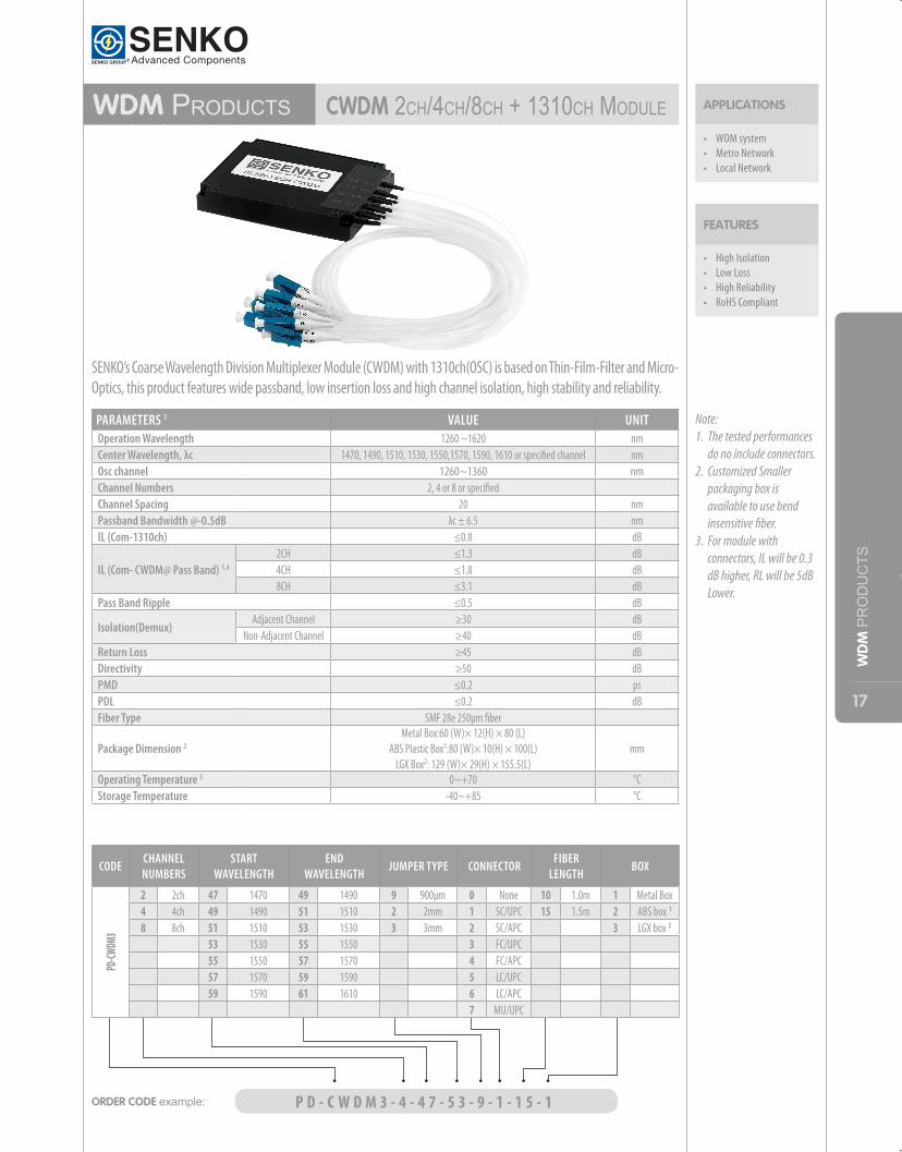
WdM ProduCtS CWdM2Ch/4Ch/8Ch+1310ChModule
• High Isolation• Low Loss• High Reliability• RoHS Compliant
FEATURES
APPLICATIONS
• WDM system• Metro Network• Local Network
PARAMETERS 1 VALUE UNITOperation Wavelength 1260 ~1620 nmCenter Wavelength, λc 1470, 1490, 1510, 1530, 1550,1570, 1590, 1610 or specified channel nmOsc channel 1260~1360 nmChannel Numbers 2, 4 or 8 or specifiedChannel Spacing 20 nmPassband Bandwidth @-0.5dB λc ± 6.5 nmIL (Com-1310ch) ≤0.8 dB
IL (Com- CWDM@ Pass Band) 1,4
2CH ≤1.3 dB4CH ≤1.8 dB8CH ≤3.1 dB
Pass Band Ripple ≤0.5 dB
Isolation(Demux)Adjacent Channel ≥30 dB
Non-Adjacent Channel ≥40 dBReturn Loss ≥45 dBDirectivity ≥50 dBPMD ≤0.2 psPDL ≤0.2 dBFiber Type SMF 28e 250μm fiber
Package Dimension 2 Metal Box:60 (W)× 12(H) × 80 (L)
ABS Plastic Box1:80 (W)× 10(H) × 100(L)LGX Box2: 129 (W)× 29(H) × 155.5(L)
mm
Operating Temperature 3 0~+70 °CStorage Temperature -40~+85 °C
SENKO’s Coarse Wavelength Division Multiplexer Module (CWDM) with 1310ch(OSC) is based on Thin-Film-Filter and Micro-Optics, this product features wide passband, low insertion loss and high channel isolation, high stability and reliability.
Note: 1. The tested performances
do no include connectors.2. Customized Smaller
packaging box is available to use bend insensitive fiber.
3. For module with connectors, IL will be 0.3 dB higher, RL will be 5dB Lower.
ORDER CODE example: P D - C W D M 3 - 4 - 4 7 - 5 3 - 9 - 1 - 1 5 - 1
CODECHANNEL NUMBERS
START WAVELENGTH
END WAVELENGTH
JUMPER TYPE CONNECTORFIBER
LENGTHBOX
PD-CW
DM3
2 2ch 47 1470 49 1490 9 900μm 0 None 10 1.0m 1 Metal Box4 4ch 49 1490 51 1510 2 2mm 1 SC/UPC 15 1.5m 2 ABS box 1
8 8ch 51 1510 53 1530 3 3mm 2 SC/APC 3 LGX box 2
53 1530 55 1550 3 FC/UPC55 1550 57 1570 4 FC/APC57 1570 59 1590 5 LC/UPC59 1590 61 1610 6 LC/APC
7 MU/UPC
18
WD
M PRODUCTS
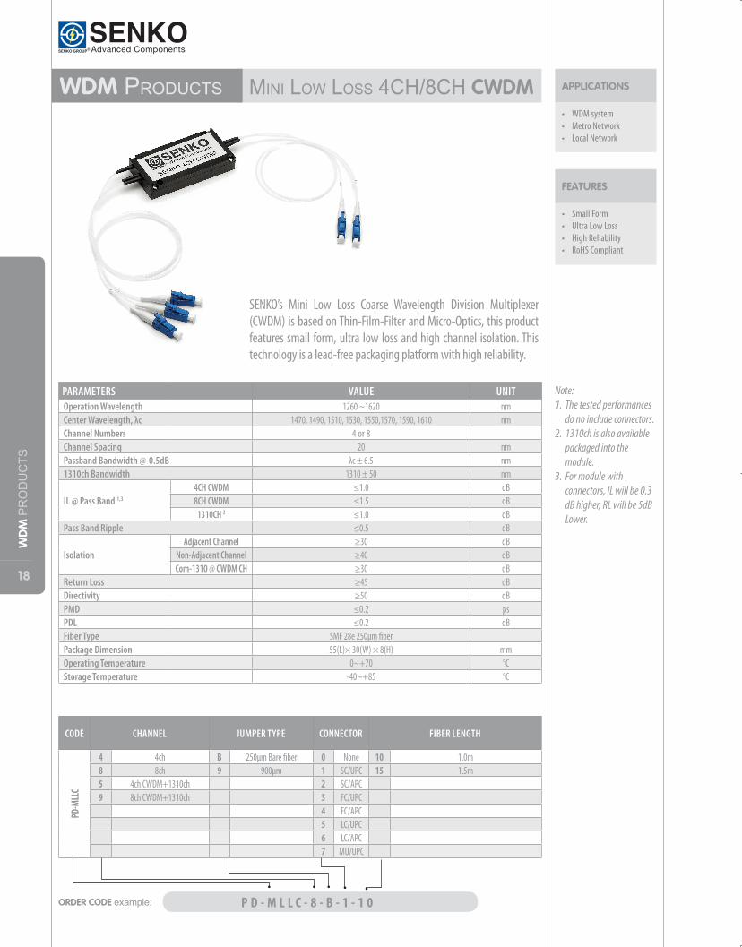
WdM ProduCtS MiniloWloSS4Ch/8ChCWdM
• Small Form• Ultra Low Loss• High Reliability• RoHS Compliant
FEATURES
APPLICATIONS
• WDM system• Metro Network• Local Network
Note: 1. The tested performances
do no include connectors.2. 1310ch is also available
packaged into the module.
3. For module with connectors, IL will be 0.3 dB higher, RL will be 5dB Lower.
ORDER CODE example: P D - M L L C - 8 - B - 1 - 1 0
CODE CHANNEL JUMPER TYPE CONNECTOR FIBER LENGTH
PD-M
LLC
4 4ch B 250μm Bare fiber 0 None 10 1.0m8 8ch 9 900μm 1 SC/UPC 15 1.5m5 4ch CWDM+1310ch 2 SC/APC9 8ch CWDM+1310ch 3 FC/UPC
4 FC/APC5 LC/UPC6 LC/APC7 MU/UPC
PARAMETERS VALUE UNITOperation Wavelength 1260 ~1620 nmCenter Wavelength, λc 1470, 1490, 1510, 1530, 1550,1570, 1590, 1610 nmChannel Numbers 4 or 8Channel Spacing 20 nmPassband Bandwidth @-0.5dB λc ± 6.5 nm1310ch Bandwidth 1310 ± 50 nm
IL @ Pass Band 1,3
4CH CWDM ≤1.0 dB8CH CWDM ≤1.5 dB
1310CH 2 ≤1.0 dBPass Band Ripple ≤0.5 dB
IsolationAdjacent Channel ≥30 dB
Non-Adjacent Channel ≥40 dBCom-1310 @ CWDM CH ≥30 dB
Return Loss ≥45 dBDirectivity ≥50 dBPMD ≤0.2 psPDL ≤0.2 dBFiber Type SMF 28e 250µm fiber Package Dimension 55(L)× 30(W) × 8(H) mmOperating Temperature 0~+70 °CStorage Temperature -40~+85 °C
SENKO’s Mini Low Loss Coarse Wavelength Division Multiplexer (CWDM) is based on Thin-Film-Filter and Micro-Optics, this product features small form, ultra low loss and high channel isolation. This technology is a lead-free packaging platform with high reliability.
19
WD
M PRODUCTS
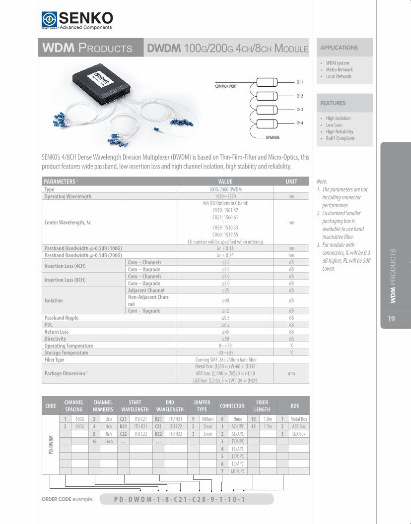
WdM ProduCtS dWdM100g/200g4Ch/8ChModule
• High Isolation• Low Loss• High Reliability• RoHS Compliant
FEATURES
APPLICATIONS
• WDM system• Metro Network• Local Network
SENKO’s 4/8CH Dense Wavelength Division Multiplexer (DWDM) is based on Thin-Film-Filter and Micro-Optics, this product features wide passband, low insertion loss and high channel isolation, high stability and reliability.
Note: 1. The parameters are not
including connector performance.
2. Customized Smaller packaging box is available to use bend insensitive fiber.
3. For module with connectors, IL will be 0.3 dB higher, RL will be 5dB Lower.
ORDER CODE example: P D - D W D M - 1 - 8 - C 2 1 - C 2 8 - 9 - 1 - 1 0 - 1
CODECHANNEL SPACING
CHANNEL NUMBERS
START WAVELENGTH
END WAVELENGTH
JUMPER TYPE
CONNECTORFIBER
LENGTH BOX
PD-D
WDM
1 100G 2 2ch C21 ITU C21 H21 ITU H21 9 900um 0 None 10 1.0m 1 Metal Box2 200G 4 4ch H21 ITU H21 C22 ITU C22 2 2mm 1 SC/UPC 15 1.5m 2 ABS Box
8 8ch C22 ITU C22 H22 ITU H22 3 3mm 2 SC/APC 3 LGX Box16 16ch … … … … 3 FC/UPC
4 FC/APC5 LC/UPC6 LC/APC7 MU/UPC
PARAMETERS 1 VALUE UNITType 100G/200G DWDMOperating Wavelength 1520~1570 nm
Center Wavelength, λc
4ch ITU Options in C band:CH20: 1561.42CH21: 1560.61…CH59: 1530.33CH60: 1529.55
Ch number will be specified when ordering
nm
Passband Bandwidth @-0.5dB (100G) λc ± 0.11 nmPassband Bandwidth @-0.5dB (200G) λc ± 0.25 nm
Insertion Loss (4CH) Com – Channels ≤2.0 dBCom – Upgrade ≤2.0 dB
Insertion Loss (8CH) Com – Channels ≤3.0 dBCom – Upgrade ≤3.0 dB
Isolation
Adjacent Channel ≥25 dBNon-Adjacent Chan-nel
≥40 dB
Com – Upgrade ≥12 dBPassband Ripple ≤0.5 dBPDL ≤0.2 dBReturn Loss ≥45 dBDirectivity ≥50 dBOperating Temperature 0~+70 °CStorage Temperature -40~+85 °CFiber Type Corning SMF-28e 250um bare fiber
Package Dimension 2Metal box: (L)80 × (W)60 × (H)12ABS box: (L)100 × (W)80 × (H)10
LGX box: (L)155.5 × (W)129 × (H)29mm
20
WD
M PRODUCTS
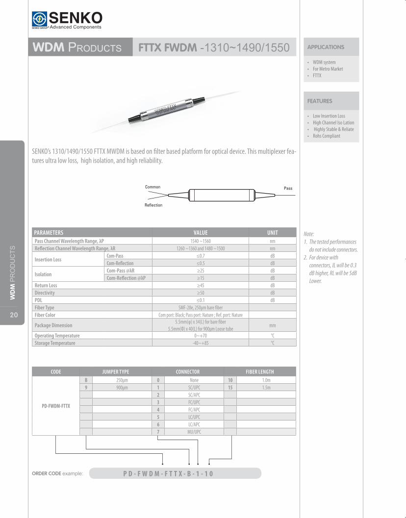
WdM ProduCtS FTTX FWdM-1310~1490/1550
• Low Insertion Loss• High Channel Iso Lation• Highly Stable & Reliate• Rohs Compliant
FEATURES
APPLICATIONS
• WDM system• For Metro Market• FTTX
PARAMETERS VALUE UNITPass Channel Wavelength Range, λP 1540 ~1560 nmReflection Channel Wavelength Range, λR 1260 ~1360 and 1480 ~1500 nm
Insertion LossCom-Pass ≤0.7 dBCom-Reflection ≤0.5 dB
Isolation Com-Pass @λR ≥25 dBCom-Reflection @λP ≥15 dB
Return Loss ≥45 dBDirectivity ≥50 dBPDL ≤0.1 dBFiber Type SMF-28e, 250μm bare fiberFiber Color Com port: Black; Pass port: Nature ; Ref. port: Nature
Package Dimension5.5mm(φ) x 34(L) for bare fiber
5.5mm(Ф) x 40(L) for 900μm Loose tubemm
Operating Temperature 0~+70 °CStorage Temperature -40~+85 °C
ORDER CODE example: P D - F W D M - F T T X - B - 1 - 1 0
CODE JUMPER TYPE CONNECTOR FIBER LENGTH
PD-FWDM-FTTX
B 250μm 0 None 10 1.0m9 900μm 1 SC/UPC 15 1.5m
2 SC/APC3 FC/UPC4 FC/APC5 LC/UPC6 LC/APC7 MU/UPC
SENKO’s 1310/1490/1550 FTTX MWDM is based on filter based platform for optical device. This multiplexer fea-tures ultra low loss, high isolation, and high reliability.
Note: 1. The tested performances
do not include connectors.2. For device with
connectors, IL will be 0.3 dB higher, RL will be 5dB Lower.
21
WD
M PRODUCTS
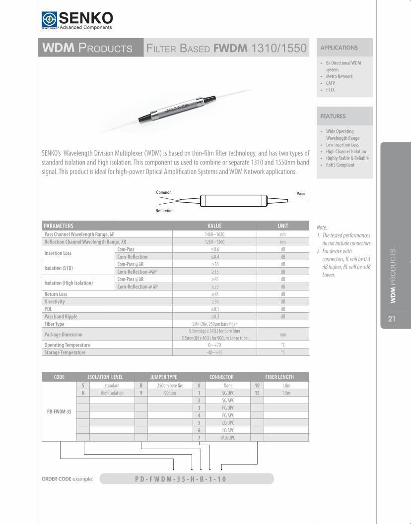
WdM ProduCtS FilterbaSedFWdM 1310/1550
• Wide Operating Wavelength Range
• Low Insertion Loss• High Channel Isolation• Highly Stable & Reliable• RoHS Compliant
FEATURES
APPLICATIONS
• Bi-Directional WDM system
• Metro Network• CATV• FTTX
PARAMETERS VALUE UNITPass Channel Wavelength Range, λP 1460~1620 nmReflection Channel Wavelength Range, λR 1260~1360 nm
Insertion LossCom-Pass ≤0.6 dBCom-Reflection ≤0.4 dB
Isolation (STD)Com-Pass @ λR ≥30 dBCom-Reflection @λP ≥15 dB
Isolation (High Isolation)Com-Pass @ λR ≥45 dBCom-Reflection @ λP ≥25 dB
Return Loss ≥45 dBDirectivity ≥50 dBPDL ≤0.1 dBPass band Ripple ≤0.3 dBFiber Type SMF-28e, 250µm bare fiber
Package Dimension5.5mm(φ) x 34(L) for bare fiber
5.5mm(Ф) x 40(L) for 900μm Loose tubemm
Operating Temperature 0~+70 °CStorage Temperature -40~+85 °C
SENKO’s Wavelength Division Multiplexer (WDM) is based on thin-film filter technology, and has two types of standard isolation and high isolation. This component us used to combine or separate 1310 and 1550nm band signal. This product is ideal for high-power Optical Amplification Systems and WDM Network applications.
ORDER CODE example: P D - F W D M - 3 5 - H - B - 1 - 1 0
CODE ISOLATION LEVEL JUMPER TYPE CONNECTOR FIBER LENGTH
PD-FWDM-35
S standard B 250um bare fire 0 None 10 1.0mH High Isolation 9 900μm 1 SC/UPC 15 1.5m
2 SC/APC3 FC/UPC4 FC/APC5 LC/UPC6 LC/APC7 MU/UPC
Note: 1. The tested performances
do not include connectors.2. For device with
connectors, IL will be 0.3 dB higher, RL will be 5dB Lower.
22
WD
M PRODUCTS
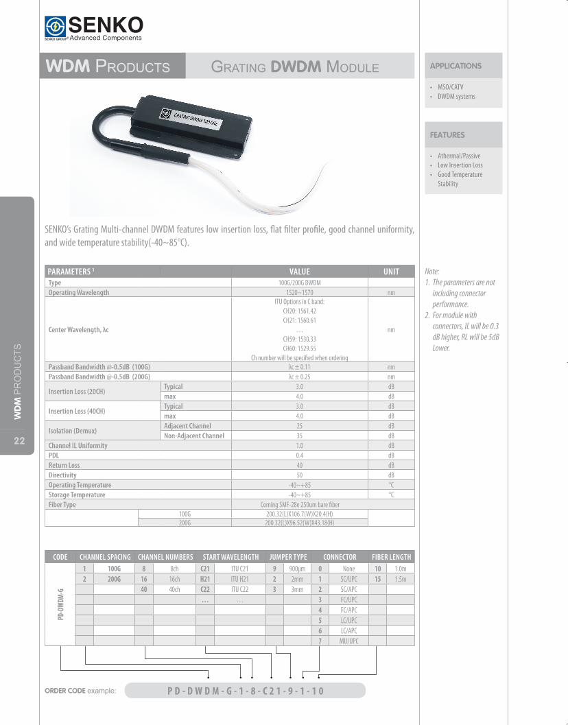
WdM ProduCtS gratingdWdMModule
• Athermal/Passive• Low Insertion Loss• Good Temperature
Stability
FEATURES
APPLICATIONS
• MSO/CATV• DWDM systems
PARAMETERS 1 VALUE UNITType 100G/200G DWDM Operating Wavelength 1520~1570 nm
Center Wavelength, λc
ITU Options in C band:CH20: 1561.42CH21: 1560.61
…CH59: 1530.33CH60: 1529.55
Ch number will be specified when ordering
nm
Passband Bandwidth @-0.5dB (100G) λc ± 0.11 nmPassband Bandwidth @-0.5dB (200G) λc ± 0.25 nm
Insertion Loss (20CH)Typical 3.0 dBmax 4.0 dB
Insertion Loss (40CH)Typical 3.0 dBmax 4.0 dB
Isolation (Demux)Adjacent Channel 25 dBNon-Adjacent Channel 35 dB
Channel IL Uniformity 1.0 dBPDL 0.4 dBReturn Loss 40 dBDirectivity 50 dBOperating Temperature -40~+85 °CStorage Temperature -40~+85 °CFiber Type Corning SMF-28e 250um bare fiber
100G 200.32(L)X106.7(W)X20.4(H)200G 200.32(L)X96.52(W)X43.18(H)
Note: 1. The parameters are not
including connector performance.
2. For module with connectors, IL will be 0.3 dB higher, RL will be 5dB Lower.
ORDER CODE example: P D - D W D M - G - 1 - 8 - C 2 1 - 9 - 1 - 1 0
CODE CHANNEL SPACING CHANNEL NUMBERS START WAVELENGTH JUMPER TYPE CONNECTOR FIBER LENGTH
PD-D
WDM
-G
1 100G 8 8ch C21 ITU C21 9 900μm 0 None 10 1.0m2 200G 16 16ch H21 ITU H21 2 2mm 1 SC/UPC 15 1.5m
40 40ch C22 ITU C22 3 3mm 2 SC/APC … … 3 FC/UPC
4 FC/APC 5 LC/UPC 6 LC/APC
7 MU/UPC
SENKO’s Grating Multi-channel DWDM features low insertion loss, flat filter profile, good channel uniformity, and wide temperature stability(-40~85°C).
23
SWIT
CH /
RO
UTI
NG
ANDATT
ENUAT
OR
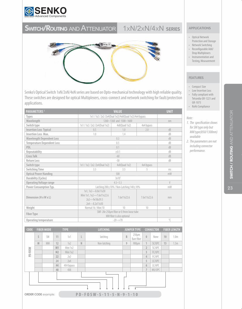
sWiTCh/RouTing andattenuator 1xn/2xn/4xnseRies
• Compact Size• Low Insertion Loss• Fully compliant with
Telcordia GR-1221 and GR-1073
• RoHs Compliance
FEATURES
APPLICATIONS
• Optical Network Protection and Storage
• Network Switching• Reconfigurable Add/
Drop Multiplexers• Instrumentation and
Testing, Measurement
PARAMETERS 1 VALUE UNITTypes 1x1 / 1x2 / 2x2 /2x4(Dual 1x2)/4x8(Quad 1x2)/4x4 bypassWavelength 1260~1360 and 1500~1600 nmSwitch type 1x1 / 1x2 / 2x2 /2x4(Dual 1x2) 4x8(Quad 1x2) 4x4 bypassInsertion Loss Typical 0.5 1.0 2.0 dBInsertion Loss Max. 1.0 1.4 dBWavelength Dependent Loss 0.3 dBTemperature Dependent Loss 0.5 dBPDL 0.1 dBRepeatability ±0.1 dBCross Talk -60 dBReturn Loss -50 dBSwitch type 1x1 / 1x2 / 2x2 /2x4(Dual 1x2) 4x8(Quad 1x2) 4x4 bypassSwitching Time 3.5 3.5 5 msOptical Power Handing 500 mWDurability (Cycles) 3x10⁷
Operating Voltage range 4.5~5.5 VPower Consumption Typ. Latching:200±10% / Non-Latching:140±10% mW
Dimension (H x W x L)
1x1, 1x2—8.8x11x30Mini 1x1, 1x2—7.6x11x22.6
2x2—9x18x39.52x4—8.2x11x30
7.6x11x22.6 7.6x11x22.6 mm
Weight Normal:16 / Mini:10 10 10 g
Fiber TypeSMF-28e 250μm fiber or 0.9mm loose tube
MM fiber is also optionalOperating temperature -20~+70 °C
Senko’s Optical Switch 1xN/2xN/4xN series are based on Opto-mechanical technology with high reliable quality. These switches are designed for optical Multiplexers, cross-connect and network switching for fault/protection applications.
Note: 1. The specification shows
for SM type only but MM type(850/1300nm) available
2. The parameters are not including connector performance.
ORDER CODE example: P D - F O S W - S - 1 1 - 5 - N - 9 - 1 - 1 0
CODE FIBER MODE TYPE LATCHING JUMPER TYPE CONNECTOR FIBER LENGTH
PD-FO
SW
S SM 11 1x1 L latching B 250μm Bare fiber
0 None 10 1.0m
M MM 12 1x2 N Non-latching 9 900μm 1 SC/UPC 15 1.5mM1 Mini 1x2 2 SC/APCM2 Mini 1x2 3 FC/UPC22 2x2 4 FC/APC24 2x4 5 LC/UPC44 4X4 bypass 6 LC/APC48 4X8 7 MU/UPC
24
SWIT
CH /
RO
UTI
NG
ANDATT
ENUAT
OR
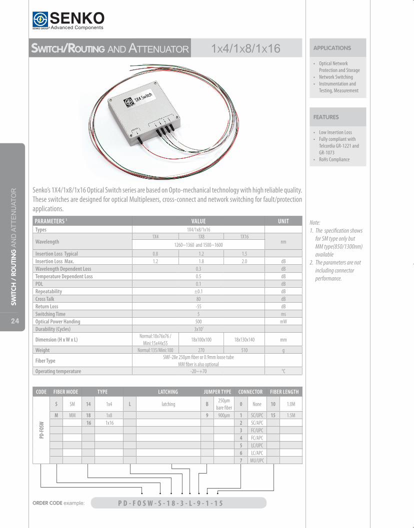
sWiTCh/RouTing andattenuator 1x4/1x8/1x16
• Low Insertion Loss• Fully compliant with
Telcordia GR-1221 and GR-1073
• RoHs Compliance
FEATURES
APPLICATIONS
• Optical Network Protection and Storage
• Network Switching• Instrumentation and
Testing, Measurement
Note: 1. The specification shows
for SM type only but MM type(850/1300nm) available
2. The parameters are not including connector performance.
ORDER CODE example: P D - F O S W - S - 1 8 - 3 - L - 9 - 1 - 1 5
CODE FIBER MODE TYPE LATCHING JUMPER TYPE CONNECTOR FIBER LENGTH
PD-FO
SW
S SM 14 1x4 L latching B 250μm bare fiber
0 None 10 1.0M
M MM 18 1x8 9 900μm 1 SC/UPC 15 1.5M 16 1x16 2 SC/APC 3 FC/UPC
4 FC/APC 5 LC/UPC 6 LC/APC
7 MU/UPC
PARAMETERS 1 VALUE UNITTypes 1X4/1x8/1x16
Wavelength1X4 1X8 1X16
nm1260~1360 and 1500~1600
Insertion Loss Typical 0.8 1.2 1.5Insertion Loss Max. 1.2 1.8 2.0 dBWavelength Dependent Loss 0.3 dBTemperature Dependent Loss 0.5 dBPDL 0.1 dBRepeatability ±0.1 dBCross Talk 80 dBReturn Loss -55 dBSwitching Time 5 msOptical Power Handing 500 mWDurability (Cycles) 3x10⁷
Dimension (H x W x L)Normal:18x76x76 /
Mini:15x44x5518x100x100 18x130x140 mm
Weight Normal:135/Mini:100 270 510 g
Fiber TypeSMF-28e 250μm fiber or 0.9mm loose tube
MM fiber is also optionalOperating temperature -20~+70 °C
Senko’s 1X4/1x8/1x16 Optical Switch series are based on Opto-mechanical technology with high reliable quality. These switches are designed for optical Multiplexers, cross-connect and network switching for fault/protection applications.
25
SWIT
CH /
RO
UTI
NG
ANDATT
ENUAT
OR
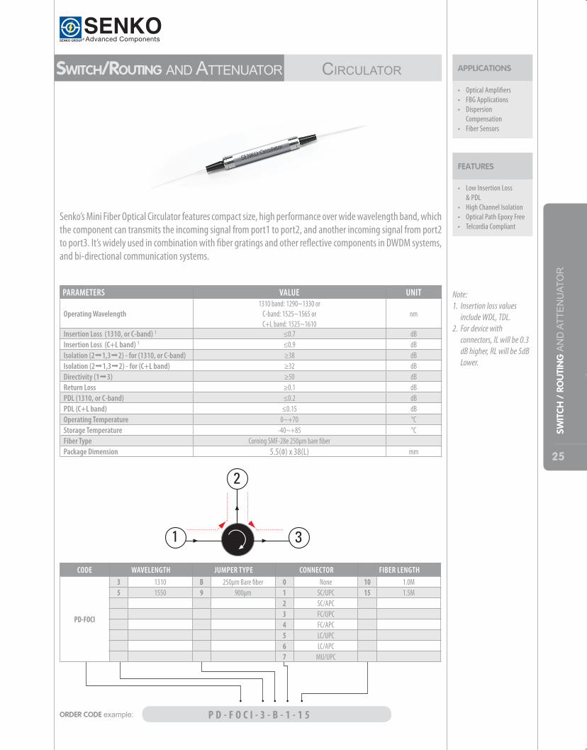
• Low Insertion Loss & PDL
• High Channel Isolation• Optical Path Epoxy Free• Telcordia Compliant
FEATURES
APPLICATIONS
• Optical Amplifiers• FBG Applications• Dispersion
Compensation• Fiber Sensors
Senko’s Mini Fiber Optical Circulator features compact size, high performance over wide wavelength band, which the component can transmits the incoming signal from port1 to port2, and another incoming signal from port2 to port3. It’s widely used in combination with fiber gratings and other reflective components in DWDM systems, and bi-directional communication systems.
PARAMETERS VALUE UNIT
Operating Wavelength 1310 band: 1290~1330 or
C-band: 1525~1565 or C+L band: 1525~1610
nm
Insertion Loss (1310, or C-band) 1 ≤0.7 dBInsertion Loss (C+L band) 1 ≤0.9 dBIsolation (2°1,3°2) - for (1310, or C-band) ≥38 dBIsolation (2°1,3°2) - for (C+L band) ≥32 dBDirectivity (1°3) ≥50 dBReturn Loss ≥0.1 dBPDL (1310, or C-band) ≤0.2 dBPDL (C+L band) ≤0.15 dBOperating Temperature 0~+70 °CStorage Temperature -40~+85 °CFiber Type Corning SMF-28e 250μm bare fiberPackage Dimension 5.5(Ф) x 38(L) mm
ORDER CODE example: P D - F O C I - 3 - B - 1 - 1 5
CODE WAVELENGTH JUMPER TYPE CONNECTOR FIBER LENGTH
PD-FOCI
3 1310 B 250μm Bare fiber 0 None 10 1.0M5 1550 9 900μm 1 SC/UPC 15 1.5M
2 SC/APC3 FC/UPC4 FC/APC5 LC/UPC6 LC/APC7 MU/UPC
sWiTCh/RouTing andattenuator CirCulator
Note: 1. Insertion loss values
include WDL, TDL.2. For device with
connectors, IL will be 0.3 dB higher, RL will be 5dB Lower.
26
SWIT
CH /
RO
UTI
NG
ANDATT
ENUAT
OR
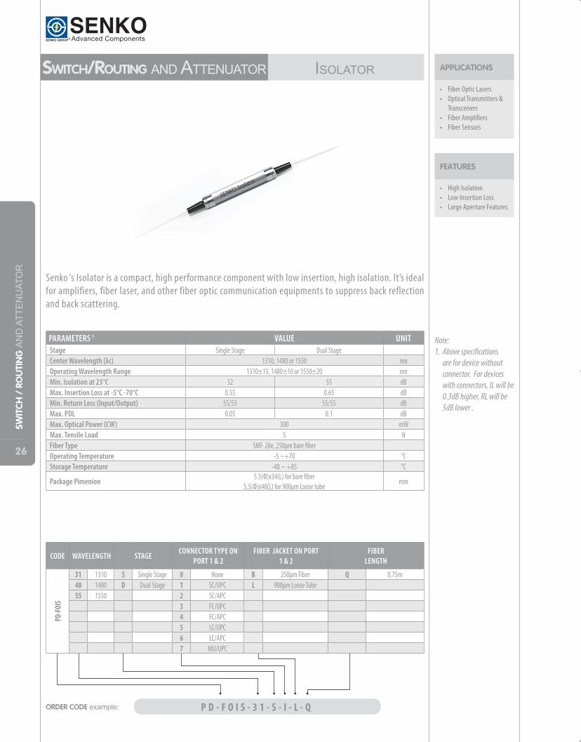
sWiTCh/RouTing andattenuator iSolator
• High Isolation • Low Insertion Loss• Large Aperture Features
FEATURES
APPLICATIONS
• Fiber Optic Lasers• Optical Transmitters &
Transceivers• Fiber Amplifiers• Fiber Sensors
Note: 1. Above specifications
are for device without connector. For devices with connectors, IL will be 0.3dB higher, RL will be 5dB lower .
PARAMETERS 1 VALUE UNITStage Single Stage Dual Stage Center Wavelength (λc) 1310, 1480 or 1550 nmOperating Wavelength Range 1310±15, 1480±10 or 1550±20 nmMin. Isolation at 23°C 32 55 dBMax. Insertion Loss at -5°C -70°C 0.55 0.65 dBMin. Return Loss (Input/Output) 55/55 55/55 dBMax. PDL 0.05 0.1 dBMax. Optical Power (CW) 300 mWMax. Tensile Load 5 NFiber Type SMF-28e, 250μm bare fiber Operating Temperature -5 ~+70 °CStorage Temperature -40 ~ +85 °C
Package Pimenion5.5(Ф)x34(L) for bare fiber
5.5(Ф)x40(L) for 900μm Loose tubemm
ORDER CODE example: P D - F O I S - 3 1 - S - I - L - Q
CODE WAVELENGTH STAGECONNECTOR TYPE ON
PORT 1 & 2FIBER JACKET ON PORT
1 & 2FIBER
LENGTH
PD-FO
IS
31 1310 S Single Stage 0 None B 250μm Fiber Q 0.75m48 1480 D Dual Stage 1 SC/UPC L 900μm Loose Tube55 1550 2 SC/APC
3 FC/UPC 4 FC/APC 5 LC/UPC 6 LC/APC 7 MU/UPC
Senko ‘s Isolator is a compact, high performance component with low insertion, high isolation. It’s ideal for amplifiers, fiber laser, and other fiber optic communication equipments to suppress back reflection and back scattering.
27
SWIT
CH /
RO
UTI
NG
ANDATT
ENUAT
OR
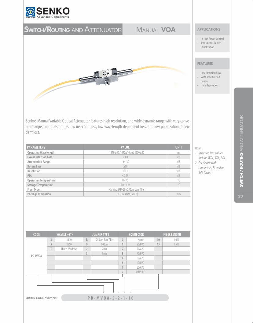
• Low Insertion Loss • Wide Attenuation
Range• High Resolution
FEATURES
APPLICATIONS
• In-line Power Control• Transmitter Power
Equalization
Note: 1. Insertion loss values
include WDL, TDL, PDL.2. For device with
connectors, RL will be 5dB lower.
PARAMETERS VALUE UNITOperating Wavelength 1310±40, 1490±10 and 1550±40 nmExcess Insertion Loss 1 ≤1.0 dBAttenuation Range 1.0~30 dBReturn Loss ≥50 dBResolution ≤0.1 dBPDL ≤0.15 dBOperating Temperature 0~70 °CStorage Temperature -40~+85 °CFiber Type Corning SMF-28e 250um bare fiberPackage Dimension 60 (L) x 16(W) x 8(H) mm
ORDER CODE example: P D - M V O A - 5 - 2 - 1 - 1 0
CODE WAVELENGTH JUMPER TYPE CONNECTOR FIBER LENGTH
PD-MVOA
3 1310 B 250μm Bare fiber 0 None 10 1.0M5 1550 9 900μm 1 SC/UPC 15 1.5MT Three Windows 2 2mm 2 SC/APC
3 3mm 3 FC/UPC4 FC/APC5 LC/UPC6 LC/APC7 MU/UPC
sWiTCh/RouTing andattenuator ManualVoA
Senko’s Manual Variable Optical Attenuator features high resolution, and wide dynamic range with very conve-nient adjustment, also it has low insertion loss, low wavelength dependent loss, and low polarization depen-dent loss.
28
PM PRODUCTS
PM Products PM PoLARizATionCoMbiner/SPlitter
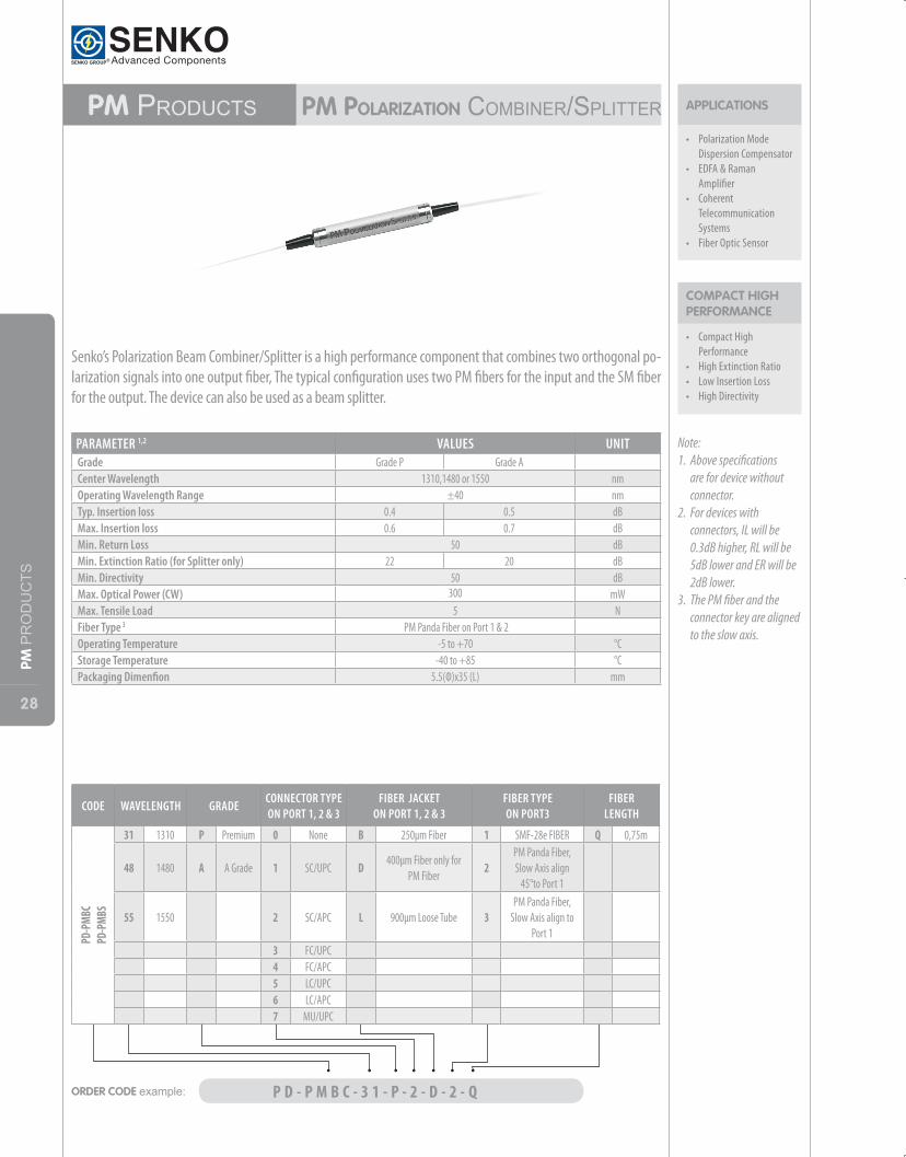
• Compact High Performance
• High Extinction Ratio• Low Insertion Loss• High Directivity
COMPACT HIGH PERFORMANCE
APPLICATIONS
• Polarization Mode Dispersion Compensator
• EDFA & Raman Amplifier
• Coherent Telecommunication Systems
• Fiber Optic Sensor
Senko’s Polarization Beam Combiner/Splitter is a high performance component that combines two orthogonal po-larization signals into one output fiber, The typical configuration uses two PM fibers for the input and the SM fiber for the output. The device can also be used as a beam splitter.
Note: 1. Above specifications
are for device without connector.
2. For devices with connectors, IL will be 0.3dB higher, RL will be 5dB lower and ER will be 2dB lower.
3. The PM fiber and the connector key are aligned to the slow axis.
PARAMETER 1,2 VALUES UNITGrade Grade P Grade A Center Wavelength 1310,1480 or 1550 nmOperating Wavelength Range ±40 nmTyp. Insertion loss 0.4 0.5 dBMax. Insertion loss 0.6 0.7 dBMin. Return Loss 50 dBMin. Extinction Ratio (for Splitter only) 22 20 dBMin. Directivity 50 dBMax. Optical Power (CW) 300 mWMax. Tensile Load 5 NFiber Type 3 PM Panda Fiber on Port 1 & 2 Operating Temperature -5 to +70 °CStorage Temperature -40 to +85 °CPackaging Dimenfion 5.5(Ф)x35 (L) mm
ORDER CODE example: P D - P M B C - 3 1 - P - 2 - D - 2 - Q
CODE WAVELENGTH GRADECONNECTOR TYPE ON PORT 1, 2 & 3
FIBER JACKET ON PORT 1, 2 & 3
FIBER TYPE ON PORT3
FIBER LENGTH
PD-P
MBC
PD-P
MBS
31 1310 P Premium 0 None B 250μm Fiber 1 SMF-28e FIBER Q 0,75m
48 1480 A A Grade 1 SC/UPC D 400μm Fiber only for PM Fiber
2PM Panda Fiber, Slow Axis align
45°to Port 1
55 1550 2 SC/APC L 900μm Loose Tube 3PM Panda Fiber,
Slow Axis align to Port 1
3 FC/UPC4 FC/APC5 LC/UPC6 LC/APC7 MU/UPC
29
PM PRODUCTS
PM Products PM iSolator
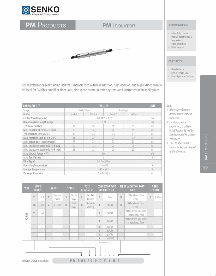
• High Isolation • Low Insertion Loss • Large Aperture Features
FEATURES
APPLICATIONS
• Fiber Optic Lasers• Optical Transmitters &
Transceivers• Fiber Amplifiers• Fiber Sensors
Senko Polarization Maintaining Isolator is characterized with low insertion, high isolation, and high extinction ratio. It’s ideal for PM fiber amplifier, fiber laser, high speed communication systems and instrumentation applications.
Note:1. Above specifications
are for device without connector.
2. For devices with connectors, IL will be 0.3dB higher, RL will be 5dB lower and ER will be 2dB lower.
3. The PM fiber and the connector key are aligned to the slow axis.
PARAMETER 1,2 VALUES UNIT Stage Single Stage Dual Stage Grade Grade P Grade A Grade P Grade A Center Wavelength (λc) 1310, 1480 or 1550 nmOperating Wavelength Range ±20 nmTyp. Peak Isolation 42 40 58 55 dBMin. Isolation at 23°C, λc ±10 nm 30 28 46 45 dBTyp. Insertion Loss at 23°C 0.4 0.5 0.5 0.7 dBMax. Insertion Loss at -5°C-70°C 0.6 0.7 0.7 0.9 dBMin. Return Loss (Input/Output) 55 55 55 55 dBMin. Extinction Ratio(only for B tyep) 20 18 20 18 dBMin. Extinction Ratio(only for F type) 25 23 25 23 dBMax. Optical Power (CW) 300 mWMax. Tensile Load 5 NFiber Type 3 PM Panda Fiber Operating Temperature -5 to +70 °CStorage Temperature -40 to +85 °CPackage Dimension 5.5(Ф)x35 (L) mm
ORDER CODE example: P D - P M I - 5 5 - P - D - F - 1 - B - S
CODEWAVE-
LENGTHGRADE STAGE
AXIS ALIGNMENT
CONNECTOR TYPE ON PORT 1 & 2
FIBER JACKET ON PORT 1 & 2
FIBER LENGTH
PD-P
MI
31 1310 P Premium Grade
S Single Stage
F Fast Axis Blocked
0 None B 250μm Panda Bare Fiber
Q 0.75m
48 1480 A A Grade D Dual Stage
B Both Axis Working
1 SC/UPC D 400μm Panda Bare Fiber
55 1550 2 SC/APC L 900μm Loose Tube with 400μm Panda fiber
3 FC/UPC T 900μm Loose Tube with 250μm Panda fiber
4 FC/APC5 LC/UPC6 LC/APC7 MU/UPC
30
PM PRODUCTS
PM Products PM FiLTeRCouPler
• Low Insertion Loss • High Return Loss
FEATURES
APPLICATIONS
• Fiber Optic Instruments• Fiber Amplifiers• Fiber Lasers• Fiber Sensors
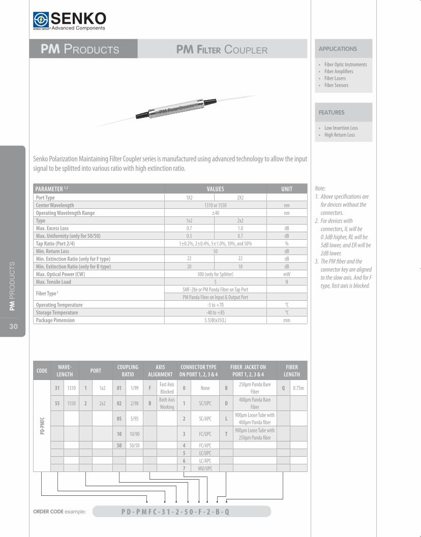
Senko Polarization Maintaining Filter Coupler series is manufactured using advanced technology to allow the input signal to be splitted into various ratio with high extinction ratio.
Note:1. Above specifications are
for devices without the connectors.
2. For devices with connectors, IL will be 0.3dB higher, RL will be 5dB lower, and ER will be 2dB lower.
3. The PM fiber and the connector key are aligned to the slow axis. And for F type, fast axis is blocked.
PARAMETER 1,2 VALUES UNIT Port Type 1X2 2X2 Center Wavelength 1310 or 1550 nmOperating Wavelength Range ±40 nmType 1x2 2x2 Max. Excess Loss 0.7 1.0 dBMax. Uniformity (only for 50/50) 0.5 0.7 dBTap Ratio (Port 2/4) 1±0.2%, 2±0.4%, 5±1.0%, 10%, and 50% %Min. Return Loss 50 dBMin. Extinction Ratio (only for F type) 22 22 dBMin. Extinction Ratio (only for B type) 20 18 dBMax. Optical Power (CW) 300 (only for Splitter) mWMax. Tensile Load 5 N
Fiber Type 3 SMF-28e or PM Panda Fiber on Tap PortPM Panda Fiber on lnput & Output Port
Operating Temperature -5 to +70 °CStorage Temperature -40 to +85 °CPackage Pimension 5.5(Ф)x35(L) mm
ORDER CODE example: P D - P M F C - 3 1 - 2 - 5 0 - F - 2 - B - Q
CODEWAVE-
LENGTHPORT
COUPLING RATIO
AXIS ALIGNMENT
CONNECTOR TYPE ON PORT 1, 2, 3 & 4
FIBER JACKET ON PORT 1, 2, 3 & 4
FIBER LENGTH
PD-P
MFC
31 1310 1 1x2 01 1/99 F Fast Axis Blocked
0 None B 250μm Panda Bare Fiber
Q 0.75m
55 1550 2 2x2 02 2/98 B Both Axis Working
1 SC/UPC D 400μm Panda Bare Fiber
05 5/95 2 SC/APC L 900μm Loose Tube with 400μm Panda fiber
10 10/90 3 FC/UPC T 900μm Loose Tube with 250μm Panda fiber
50 50/50 4 FC/APC5 LC/UPC6 LC/APC7 MU/UPC
31
PM PRODUCTS
• Low Insertion Loss • High Return Loss
FEATURES
PM Products PM oPtiCalCirCulator APPLICATIONS
• Fiber Optic Instruments• Fiber Sensors• Coherent Detecting• Research
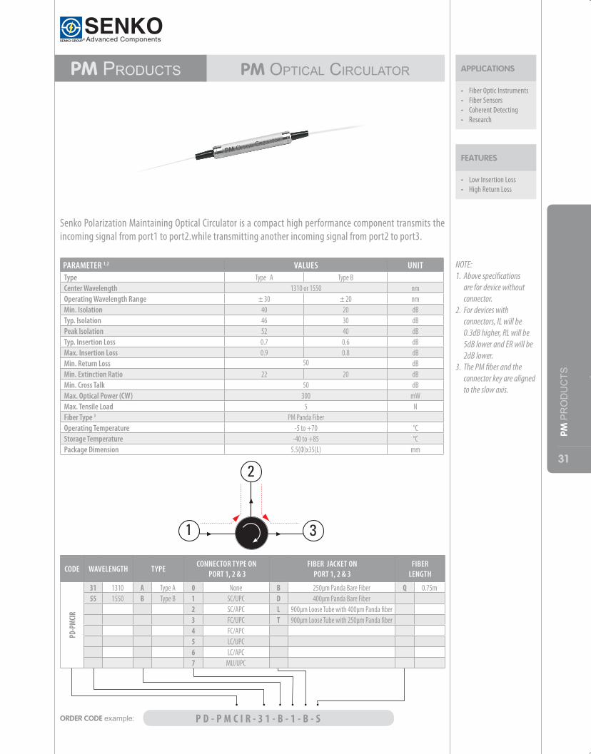
Senko Polarization Maintaining Optical Circulator is a compact high performance component transmits the incoming signal from port1 to port2.while transmitting another incoming signal from port2 to port3.
NOTE:1. Above specifications
are for device without connector.
2. For devices with connectors, IL will be 0.3dB higher, RL will be 5dB lower and ER will be 2dB lower.
3. The PM fiber and the connector key are aligned to the slow axis.
PARAMETER 1,2 VALUES UNIT Type Type A Type B Center Wavelength 1310 or 1550 nmOperating Wavelength Range ± 30 ± 20 nmMin. Isolation 40 20 dBTyp. Isolation 46 30 dBPeak Isolation 52 40 dBTyp. Insertion Loss 0.7 0.6 dBMax. Insertion Loss 0.9 0.8 dBMin. Return Loss 50 dBMin. Extinction Ratio 22 20 dBMin. Cross Talk 50 dBMax. Optical Power (CW) 300 mWMax. Tensile Load 5 NFiber Type 3 PM Panda Fiber Operating Temperature -5 to +70 °CStorage Temperature -40 to +85 °CPackage Dimension 5.5(Ф)x35(L) mm
ORDER CODE example: P D - P M C I R - 3 1 - B - 1 - B - S
CODE WAVELENGTH TYPECONNECTOR TYPE ON
PORT 1, 2 & 3FIBER JACKET ON
PORT 1, 2 & 3FIBER
LENGTH
PD-P
MCIR
31 1310 A Type A 0 None B 250μm Panda Bare Fiber Q 0.75m55 1550 B Type B 1 SC/UPC D 400μm Panda Bare Fiber
2 SC/APC L 900μm Loose Tube with 400μm Panda fiber3 FC/UPC T 900μm Loose Tube with 250μm Panda fiber4 FC/APC5 LC/UPC6 LC/APC7 MU/UPC
32
PM PRODUCTS
PM ProduCtSPMFilterWavelengthdiviSionMultiPlexerS
• Low Insertion Loss • High Return Loss • High Isolation
FEATURES
APPLICATIONS
• Fiber Optic Instruments• Raman Amplifiers• EDFAs• Fiber Sensors
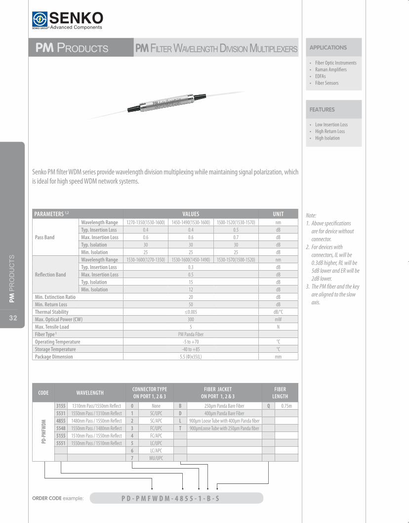
Senko PM filter WDM series provide wavelength division multiplexing while maintaining signal polarization, which is ideal for high speed WDM network systems.
Note:1. Above specifications
are for device without connector.
2. For devices with connectors, IL will be 0.3dB higher, RL will be 5dB lower and ER will be 2dB lower.
3. The PM fiber and the key are aligned to the slow axis.
PARAMETERS 1,2 VALUES UNIT
Pass Band
Wavelength Range 1270-1350(1530-1600) 1450-1490(1530-1600) 1500-1520(1530-1570) nmTyp. Insertion Loss 0.4 0.4 0.5 dBMax. Insertion Loss 0.6 0.6 0.7 dBTyp. Isolation 30 30 30 dBMin. Isolation 25 25 25 dB
Reflection Band
Wavelength Range 1530-1600(1270-1350) 1530-1600(1450-1490) 1530-1570(1500-1520) nmTyp. Insertion Loss 0.3 dBMax. Insertion Loss 0.5 dBTyp. Isolation 15 dBMin. Isolation 12 dB
Min. Extinction Ratio 20 dBMin. Return Loss 50 dBThermal Stability ≤0.005 dB/°CMax. Optical Power (CW) 300 mWMax. Tensile Load 5 NFiber Type 3 PM Panda Fiber Operating Temperature -5 to +70 °CStorage Temperature -40 to +85 °CPackage Dimension 5.5 (Ф)x35(L) mm
ORDER CODE example: P D - P M F W D M - 4 8 5 5 - 1 - B - S
CODE WAVELENGTHCONNECTOR TYPE ON PORT 1, 2 & 3
FIBER JACKET ON PORT 1, 2 & 3
FIBER LENGTH
PD-P
MFW
DM
3155 1310nm Pass/1550nm Reflect 0 None B 250μm Panda Bare Fiber Q 0.75m5531 1550nm Pass / 1310nm Reflect 1 SC/UPC D 400μm Panda Bare Fiber4855 1480nm Pass / 1550nm Reflect 2 SC/APC L 900μm Loose Tube with 400μm Panda fiber5548 1550nm Pass / 1480nm Reflect 3 FC/UPC T 900μmLoose Tube with 250μm Panda fiber5155 1510nm Pass / 1550nm Reflect 4 FC/APC5551 1550nm Pass / 1510nm Reflect 5 LC/UPC
6 LC/APC7 MU/UPC
33
PM PRODUCTS
• High Extinction Ratio• Low Insertion Loss • High Return Loss
FEATURES
• Communication Systems• Fiber Sensors• Test Instrumentations • Research
APPLICATIONS PM Products in-LinePolarizer
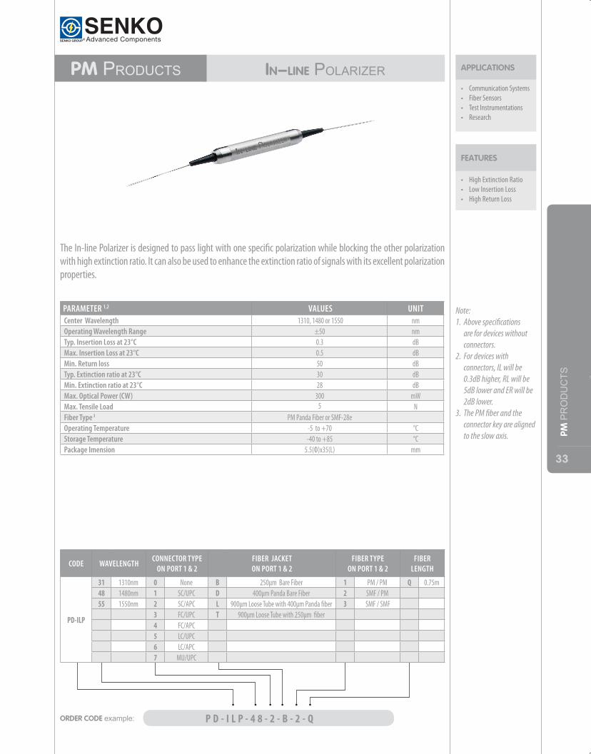
The In-line Polarizer is designed to pass light with one specific polarization while blocking the other polarization with high extinction ratio. It can also be used to enhance the extinction ratio of signals with its excellent polarization properties.
Note:1. Above specifications
are for devices without connectors.
2. For devices with connectors, IL will be 0.3dB higher, RL will be 5dB lower and ER will be 2dB lower.
3. The PM fiber and the connector key are aligned to the slow axis.
PARAMETER 1,2 VALUES UNITCenter Wavelength 1310, 1480 or 1550 nmOperating Wavelength Range ±50 nmTyp. Insertion Loss at 23°C 0.3 dBMax. Insertion Loss at 23°C 0.5 dBMin. Return loss 50 dBTyp. Extinction ratio at 23°C 30 dBMin. Extinction ratio at 23°C 28 dBMax. Optical Power (CW) 300 mWMax. Tensile Load 5 NFiber Type 3 PM Panda Fiber or SMF-28e Operating Temperature -5 to +70 °CStorage Temperature -40 to +85 °CPackage Imension 5.5(Ф)x35(L) mm
ORDER CODE example: P D - I L P - 4 8 - 2 - B - 2 - Q
CODE WAVELENGTHCONNECTOR TYPE
ON PORT 1 & 2 FIBER JACKET ON PORT 1 & 2
FIBER TYPE ON PORT 1 & 2
FIBER LENGTH
PD-ILP
31 1310nm 0 None B 250μm Bare Fiber 1 PM / PM Q 0.75m48 1480nm 1 SC/UPC D 400μm Panda Bare Fiber 2 SMF / PM55 1550nm 2 SC/APC L 900μm Loose Tube with 400μm Panda fiber 3 SMF / SMF
3 FC/UPC T 900μm Loose Tube with 250μm fiber4 FC/APC5 LC/UPC6 LC/APC7 MU/UPC
34
ENG
INEE
RIN
G S
ERVI
CES
engineeRing seRViCes
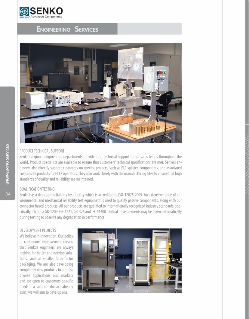
PRODUCT TECHNICAL SUPPORTSenko’s regional engineering departments provide local technical support to our sales teams throughout the world. Product specialists are available to ensure that customers’ technical specifications are met. Senko’s en-gineers also directly support customers on specific projects, such as PLC splitter, components, and associated customized products for FTTX operators. They also work closely with the manufacturing sites to ensure that high standards of quality and reliability are maintained.
QUALIFICATION TESTINGSenko has a dedicated reliability test facility which is accredited to ISO-17025:2005. An extensive range of en-vironmental and mechanical reliability test equipment is used to qualify passive components, along with our connector based products. All our products are qualified to internationally recognized industry standards, spe-cifically Telcordia GR-1209, GR-1221, GR-326 and IEC 61300. Optical measurements may be taken automatically during testing to observe any degradation in performance.
DEVELOPMENT PEOJECTSWe believe in innovation. Our policy of continuous improvement means that Senko’s engineers are always looking for better engineering solu-tions, such as smaller form factor packaging. We are also developing completely new products to address diverse applications and markets and are open to customers’ specific needs-if a solution doesn’t already exist, we will aim to develop one.