Embed Size (px)
Citation preview
Passive Optical Network Design- Architectures, Topologies and Products
Teresa BazzleJanuary 22, 2014
Telecom Commercial Operations © 2014 Corning Incorporated 2
Agenda
• Today’s session– PON Architectures and Topologies– Typical Product Sets
• Next week– Design and Cost Considerations
Telecom Commercial Operations © 2014 Corning Incorporated 3
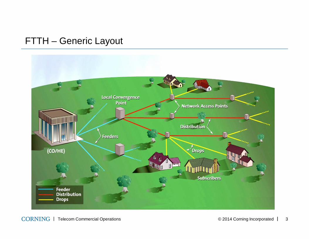
FTTH – Generic Layout
Telecom Commercial Operations © 2014 Corning Incorporated 4
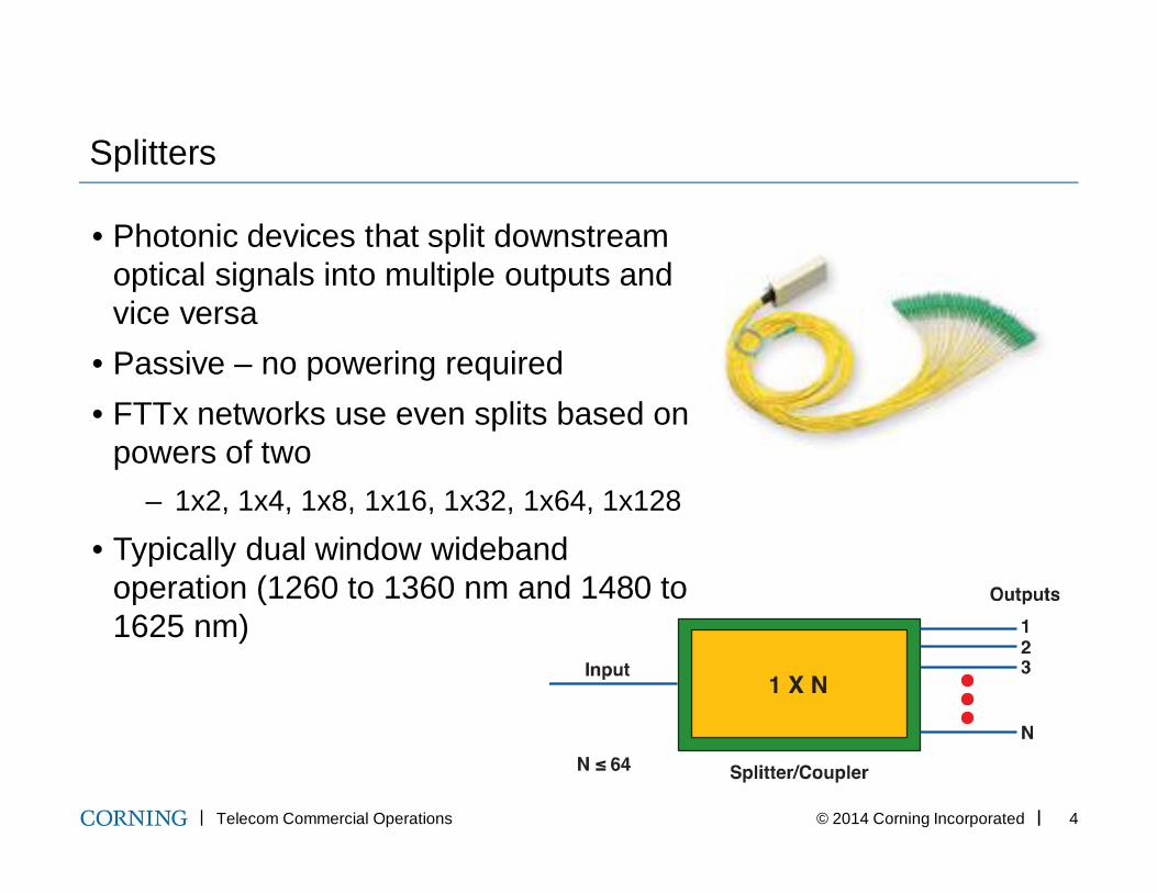
Splitters
• Photonic devices that split downstream optical signals into multiple outputs and vice versa
• Passive – no powering required• FTTx networks use even splits based on
powers of two– 1x2, 1x4, 1x8, 1x16, 1x32, 1x64, 1x128
• Typically dual window wideband operation (1260 to 1360 nm and 1480 to 1625 nm)
Telecom Commercial Operations © 2014 Corning Incorporated 5
Architecture & Topology
• Architecture– The logical or theoretical view of the network– How the network is designed, driven by the goals of the business
model and by the choice of network electronics– Location of splitter(s) is key decision
• Topology
– The physical layout/configuration of the network
– Establishes where components are physically located and physical routes of cables in OSP
– Specifies how the architecture is actually implemented in the map
Telecom Commercial Operations © 2014 Corning Incorporated 6
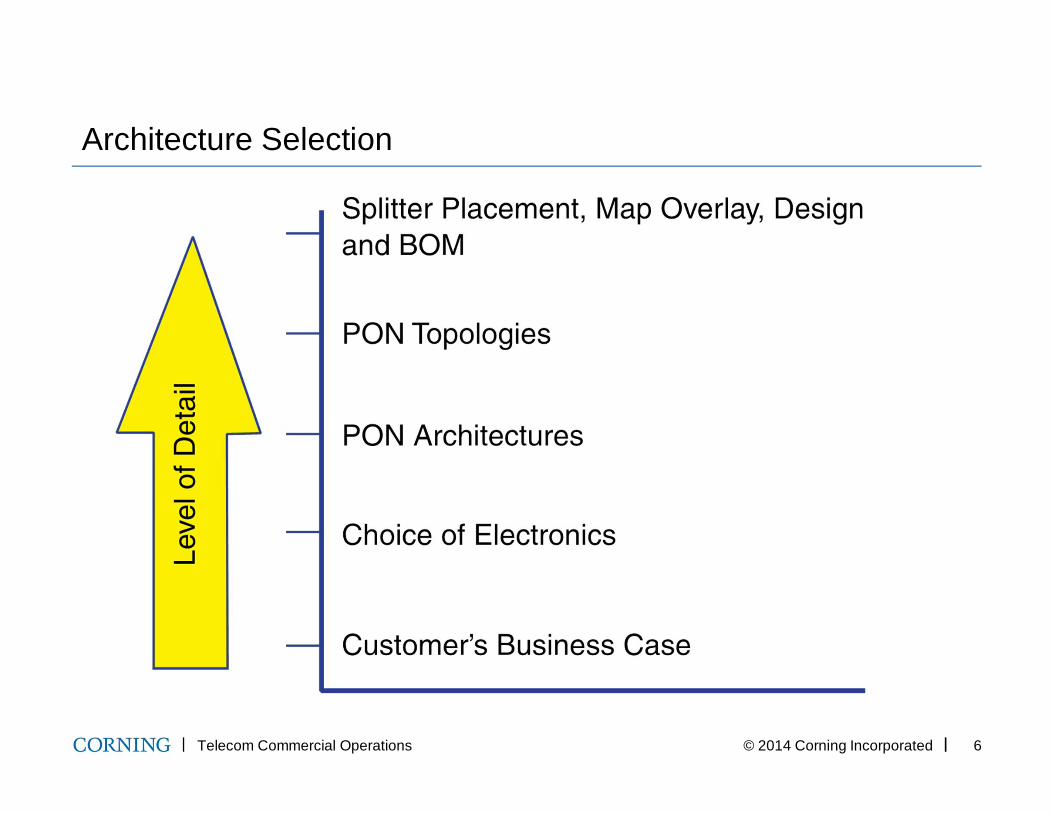
Architecture Selection
Telecom Commercial Operations © 2014 Corning Incorporated 7
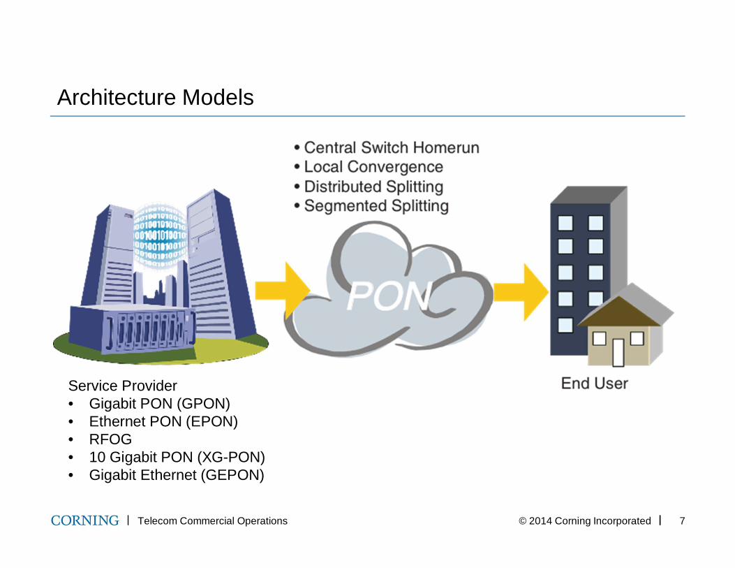
Architecture Models
Service Provider• Gigabit PON (GPON)• Ethernet PON (EPON)• RFOG• 10 Gigabit PON (XG-PON)• Gigabit Ethernet (GEPON)
Telecom Commercial Operations © 2014 Corning Incorporated 8
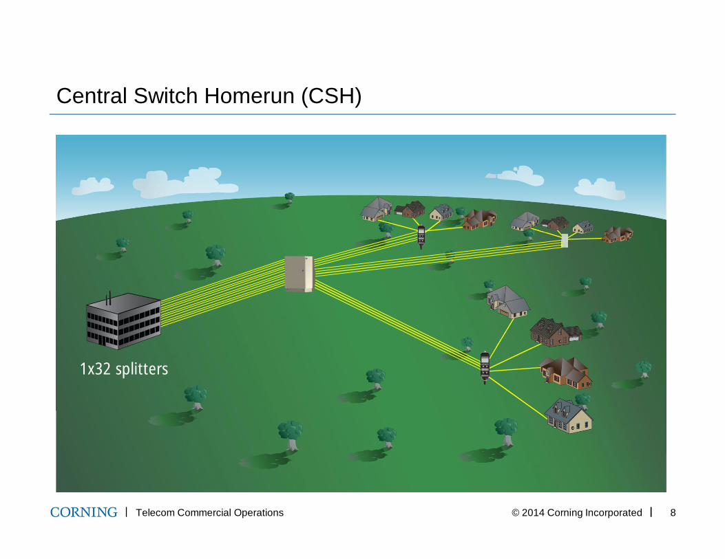
Central Switch Homerun (CSH)
1x32 splitters
Telecom Commercial Operations © 2014 Corning Incorporated 9
Central Switch Homerun
Benefits• Dedicated optical path (provider-to-subscriber)
— All splitting at central point— Only splices/connectors in field
• Highest bandwidth capacity and adaptability
• System administration from one location
Cost Considerations
• Additional up-front capital investment
• Fiber-rich feeder and distribution system
• Central Switch Center (CSC) / Central Office (CO) real estate
Telecom Commercial Operations © 2014 Corning Incorporated 10
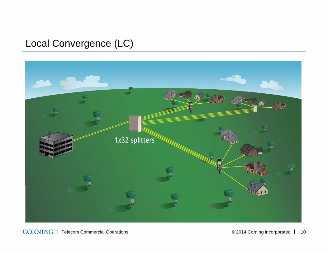
Local Convergence (LC)
1x32 splitters
Telecom Commercial Operations © 2014 Corning Incorporated 11
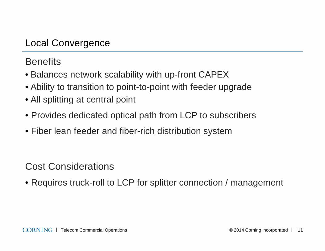
Local Convergence
Benefits• Balances network scalability with up-front CAPEX• Ability to transition to point-to-point with feeder upgrade• All splitting at central point
• Provides dedicated optical path from LCP to subscribers
• Fiber lean feeder and fiber-rich distribution system
Cost Considerations• Requires truck-roll to LCP for splitter connection / management
Telecom Commercial Operations © 2014 Corning Incorporated 12
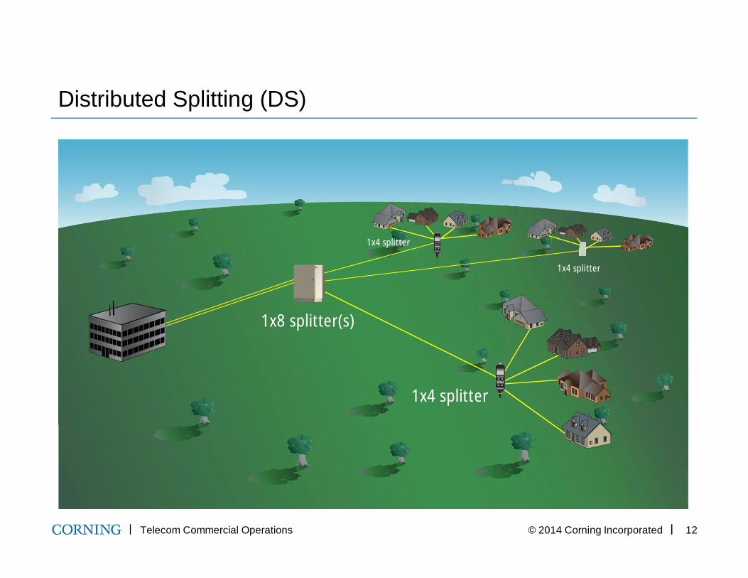
Distributed Splitting (DS)
1x4 splitter
1x4 splitter
1x4 splitter
1x8 splitter(s)
Telecom Commercial Operations © 2014 Corning Incorporated 13
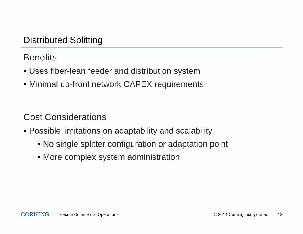
Distributed Splitting
Benefits• Uses fiber-lean feeder and distribution system• Minimal up-front network CAPEX requirements
Cost Considerations• Possible limitations on adaptability and scalability
• No single splitter configuration or adaptation point• More complex system administration
Telecom Commercial Operations © 2014 Corning Incorporated 14
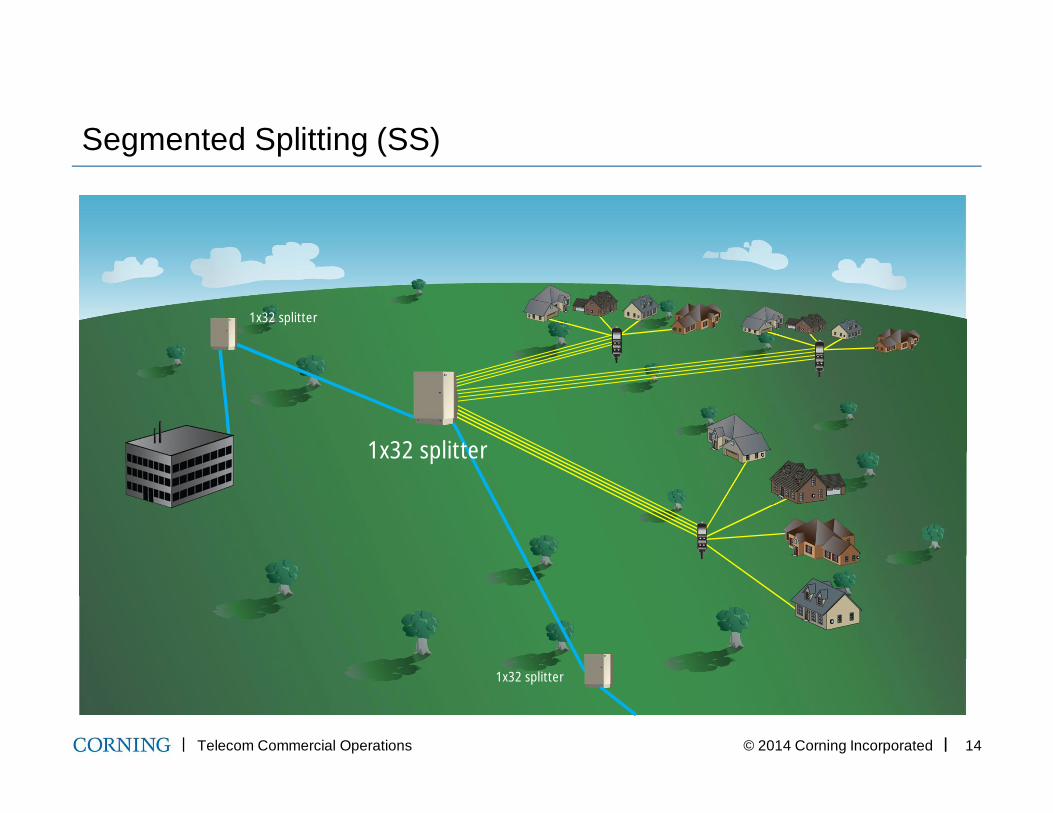
Segmented Splitting (SS)
1x32 splitter
1x32 splitter
1x32 splitter
Telecom Commercial Operations © 2014 Corning Incorporated 15
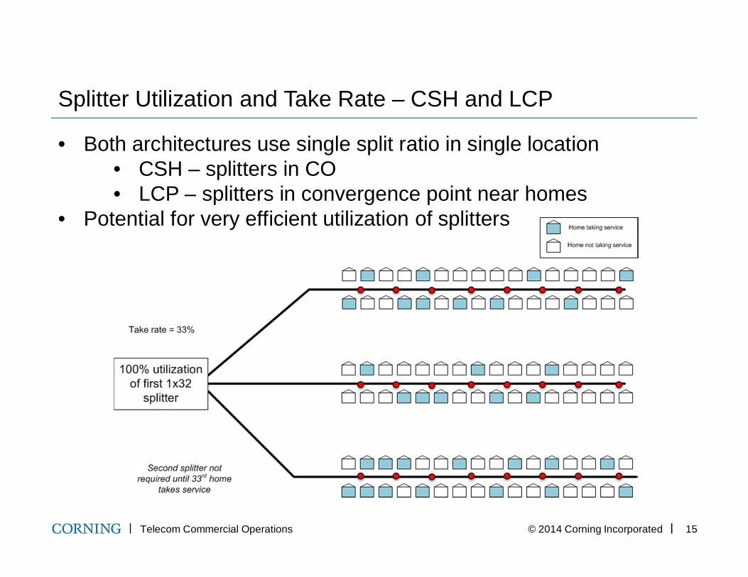
Splitter Utilization and Take Rate – CSH and LCP
• Both architectures use single split ratio in single location• CSH – splitters in CO• LCP – splitters in convergence point near homes
• Potential for very efficient utilization of splitters
Telecom Commercial Operations © 2014 Corning Incorporated 16
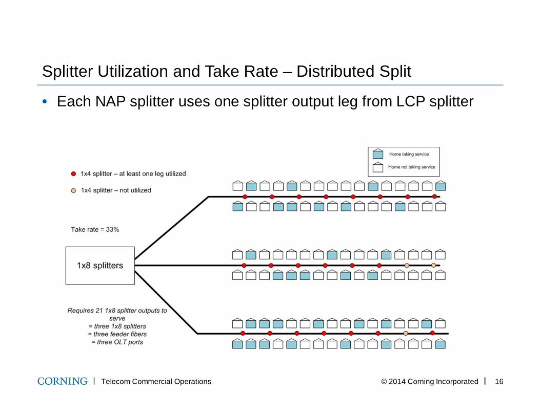
Splitter Utilization and Take Rate – Distributed Split
• Each NAP splitter uses one splitter output leg from LCP splitter
Telecom Commercial Operations © 2014 Corning Incorporated 17
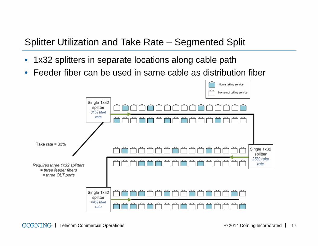
Splitter Utilization and Take Rate – Segmented Split
• 1x32 splitters in separate locations along cable path • Feeder fiber can be used in same cable as distribution fiber
Typical FTTx Product Sets
Telecom Commercial Operations © 2014 Corning Incorporated 19
PON Product Benefits
• Support fast installation / deployment of network• Minimize requirements for highly skilled labor and expensive
equipment• Provide opportunities to defer products until needed• Product quality guaranteed by manufacturers• Eliminate power requirements through all-passive network• Reduced maintenance costs through life of plant
Telecom Commercial Operations © 2014 Corning Incorporated 20
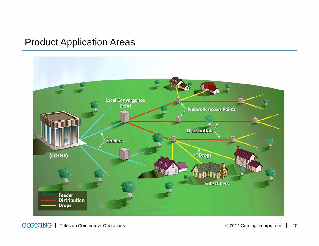
Product Application Areas
Telecom Commercial Operations © 2014 Corning Incorporated 21
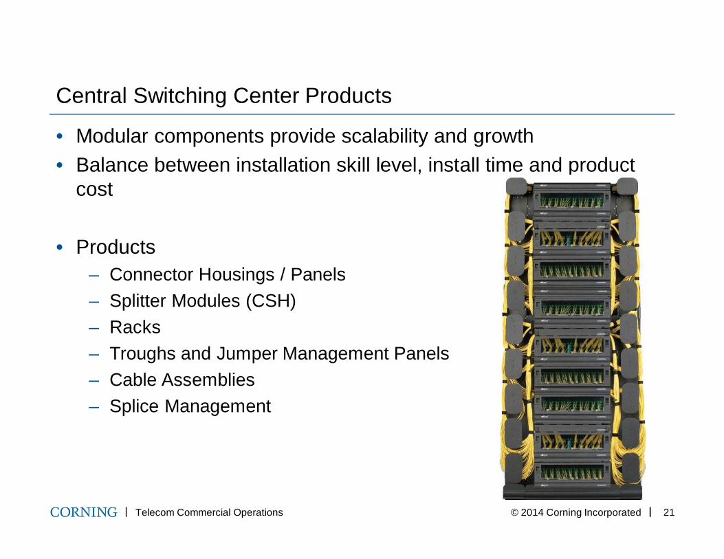
Central Switching Center Products
• Modular components provide scalability and growth• Balance between installation skill level, install time and product
cost
• Products– Connector Housings / Panels– Splitter Modules (CSH)– Racks– Troughs and Jumper Management Panels– Cable Assemblies– Splice Management
Telecom Commercial Operations © 2014 Corning Incorporated 22
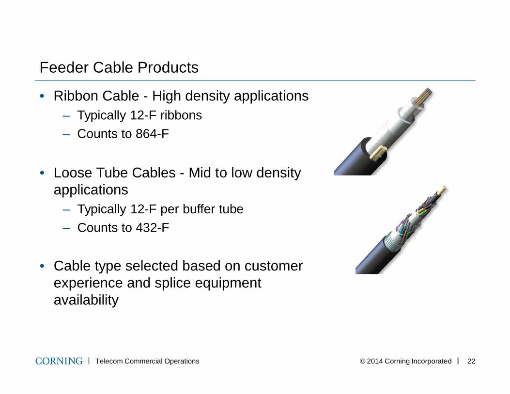
Feeder Cable Products
• Ribbon Cable - High density applications– Typically 12-F ribbons– Counts to 864-F
• Loose Tube Cables - Mid to low density applications
– Typically 12-F per buffer tube– Counts to 432-F
• Cable type selected based on customer experience and splice equipment availability
Telecom Commercial Operations © 2014 Corning Incorporated 23
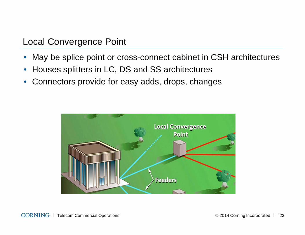
Local Convergence Point• May be splice point or cross-connect cabinet in CSH architectures• Houses splitters in LC, DS and SS architectures• Connectors provide for easy adds, drops, changes
Telecom Commercial Operations © 2014 Corning Incorporated 24
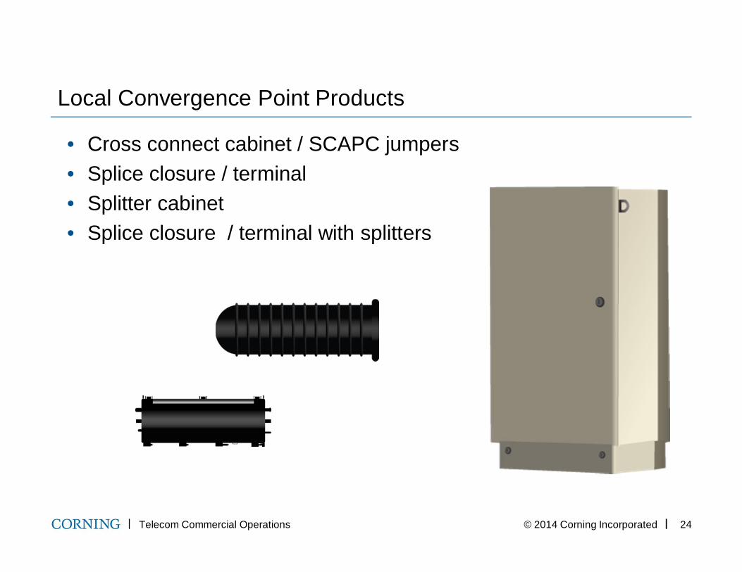
Local Convergence Point Products
• Cross connect cabinet / SCAPC jumpers• Splice closure / terminal• Splitter cabinet• Splice closure / terminal with splitters
Telecom Commercial Operations © 2014 Corning Incorporated 25
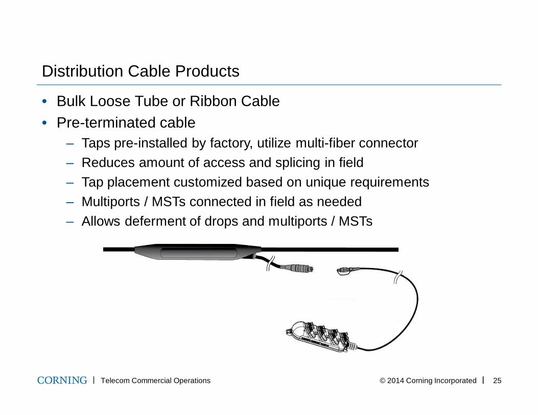
Distribution Cable Products
• Bulk Loose Tube or Ribbon Cable• Pre-terminated cable
– Taps pre-installed by factory, utilize multi-fiber connector– Reduces amount of access and splicing in field– Tap placement customized based on unique requirements– Multiports / MSTs connected in field as needed– Allows deferment of drops and multiports / MSTs
Telecom Commercial Operations © 2014 Corning Incorporated 26
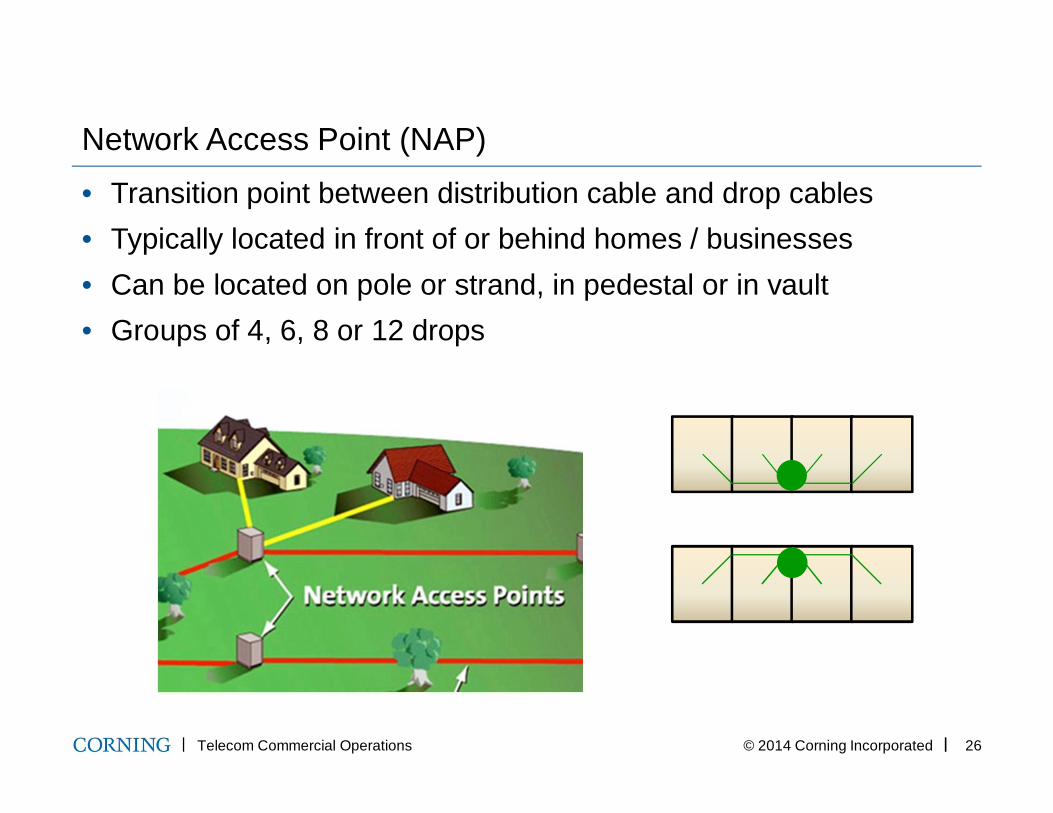
Network Access Point (NAP)• Transition point between distribution cable and drop cables• Typically located in front of or behind homes / businesses• Can be located on pole or strand, in pedestal or in vault• Groups of 4, 6, 8 or 12 drops
Telecom Commercial Operations © 2014 Corning Incorporated 27
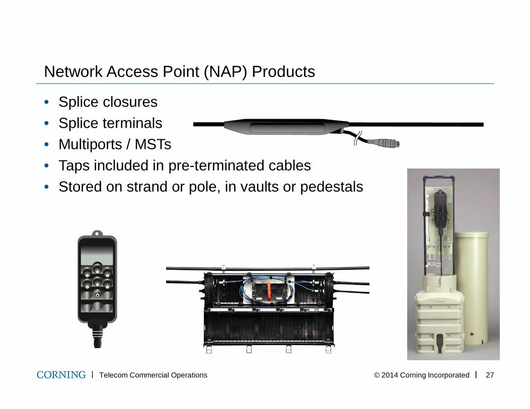
Network Access Point (NAP) Products
• Splice closures• Splice terminals• Multiports / MSTs• Taps included in pre-terminated cables• Stored on strand or pole, in vaults or pedestals
Telecom Commercial Operations © 2014 Corning Incorporated 28
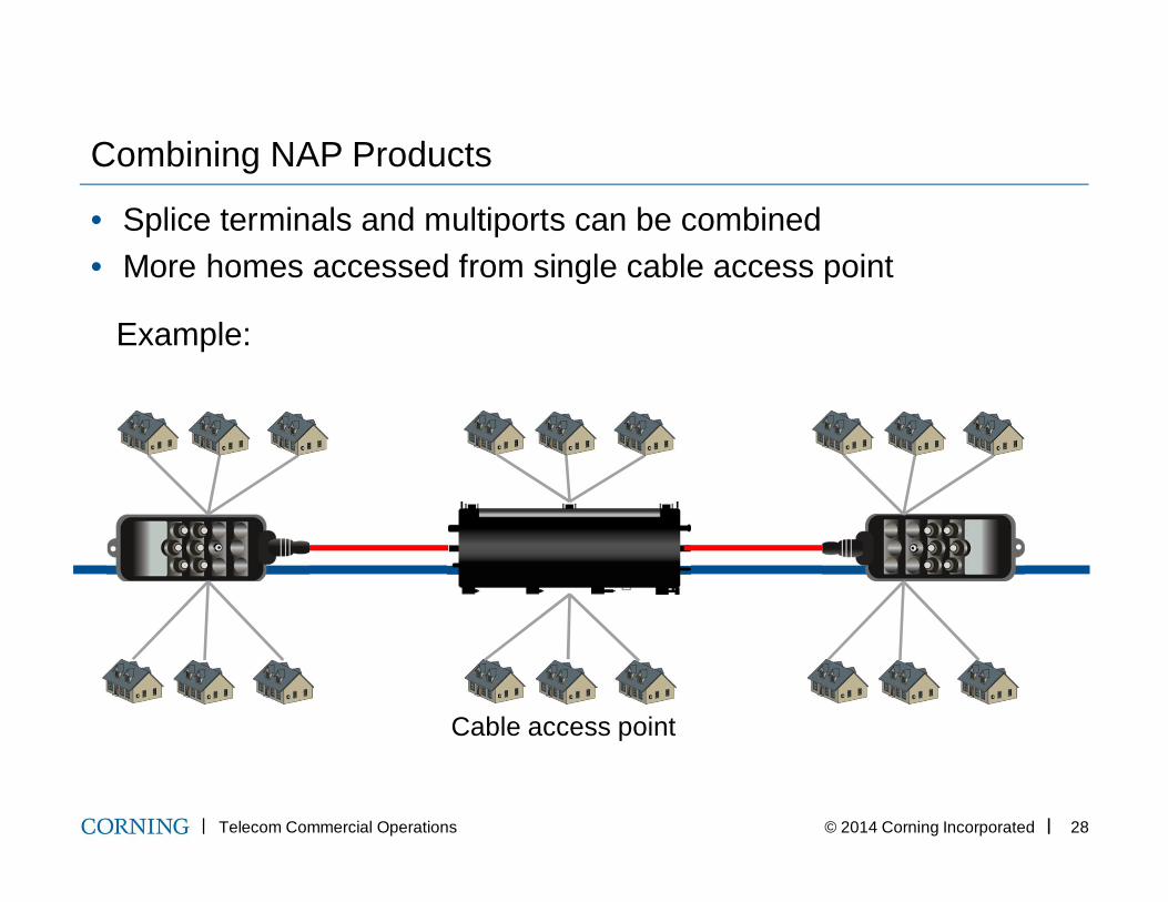
Combining NAP Products
• Splice terminals and multiports can be combined• More homes accessed from single cable access point
Example:
Cable access point
Telecom Commercial Operations © 2014 Corning Incorporated 29
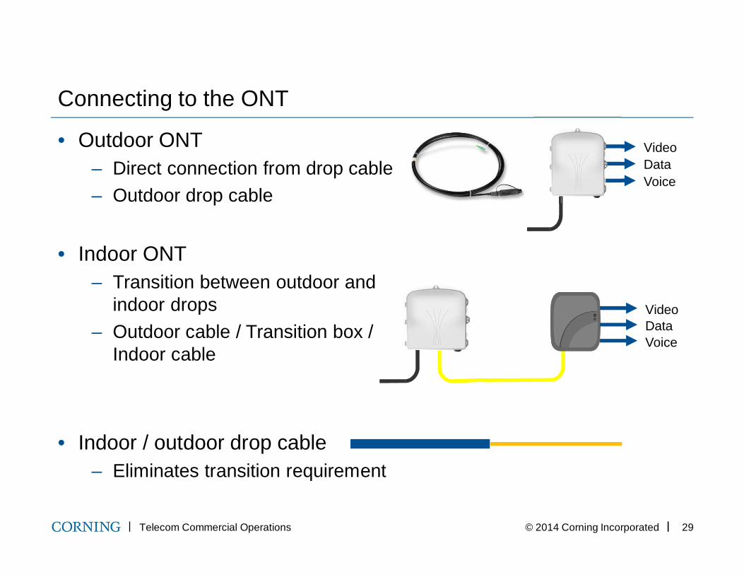
Connecting to the ONT
• Outdoor ONT– Direct connection from drop cable– Outdoor drop cable
• Indoor ONT– Transition between outdoor and
indoor drops– Outdoor cable / Transition box /
Indoor cable
• Indoor / outdoor drop cable– Eliminates transition requirement
VideoDataVoice
VideoDataVoice
Next webinar session:Passive Optical Network Design- Design and Cost Considerations
January 29th, 2:00-3:00 pm EST
Teresa BazzleSystems Engineer II / Senior EngineerCorning Cable [email protected]