Embed Size (px)
Citation preview
Passive System Accident Scenario Analysis by
Simulation
Francesco Di Maio, Enrico Zio, Tao Liu, Jiejuan Tong
To cite this version:
Francesco Di Maio, Enrico Zio, Tao Liu, Jiejuan Tong. Passive System Accident ScenarioAnalysis by Simulation. PSA 2011, Mar 2011, United States. pp.1-14, 2011. <hal-00658061>
HAL Id: hal-00658061
https://hal-supelec.archives-ouvertes.fr/hal-00658061
Submitted on 12 Jan 2012
HAL is a multi-disciplinary open accessarchive for the deposit and dissemination of sci-entific research documents, whether they are pub-lished or not. The documents may come fromteaching and research institutions in France orabroad, or from public or private research centers.
L’archive ouverte pluridisciplinaire HAL, estdestinee au depot et a la diffusion de documentsscientifiques de niveau recherche, publies ou non,emanant des etablissements d’enseignement et derecherche francais ou etrangers, des laboratoirespublics ou prives.
brought to you by COREView metadata, citation and similar papers at core.ac.uk
provided by HAL-CentraleSupelec
PASSIVE SYSTEM ACCIDENT SCENARIO ANALYSIS BY
SIMULATION
Francesco Di Maio1, Enrico Zio1,2, Tao Liu3, Jiejuan Tong3
1 Energy Department Politecnico di Milano, 20133 Milano, Italy, [email protected]
2 Ecole Centrale Paris and Supelec Grande Voie des Vignes, 92295 Chatenay-Malabry Cedex, France
[email protected] [email protected] 3 Institute of Nuclear and New Energy technology
Tsinghua University, 100084 Beijing, China
ABSTRACT
In this paper, a simulation framework of analysis is presented aiming at evaluating the safety
performance of the Residual Heat Removal system (RHRs) of the Chinese High Temperature Gas-
Cooled Reactor – Pebble Bed Modular (HTR-PM) under uncertain operation conditions, and
components and equipments failures. A transparent and fast model of the passive system has been
implemented in MATLAB to reproduce the three-interconnected natural circulation trains of the
RHRs, for removing the residual heat of the reactor core after a reactor shut-down. The model is
characterized by a one-dimensional mono-phase moving fluid, whose operation is based on
thermal-hydraulic (T-H) principles. The model is coded into a Monte Carlo (MC) failure engine for
sampling single and multiple components faults at random times and of random magnitudes.
Accidental transients of the system are simulated, highlighting equipment contribution to system
failure.
Key Words: Passive Safety System, Residual Heat Removal system (RHRs), High Temperature Gas-
Cooled Reactor – Pebble Bed Modular (HTR-PM), Scenario Analysis, Monte Carlo Simulation.
1 INTRODUCTION
Generation IV reactor systems (e.g., High Temperature Gas Cooled Reactors (HTGR)) are
resorting to the use of passive safety systems, in combination with active safety or operational
systems. As passive systems do not need external input, especially energy, to operate [IAEA, 1991],
they are expected to contribute significantly to the improvement of plant safety [Mathews et al.,
2008]. To achieve this, the design of passive systems must be supported by proper modeling and
simulation.
In this paper, we consider the Residual Heat Removal system (RHRs) of the Chinese High
Temperature Reactor-Pebble Modular (HTR-PM) [Zhengy et al., 2008]. The function of this system
is to remove the residual heat of the reactor core after shut-down. A thermal-hydraulic (T-H) model
for scenario analysis has been implemented with characteristics of transparency, for a clear
interpretation of the system response, and speed of calculation, to allow for extensive scenario
analysis.
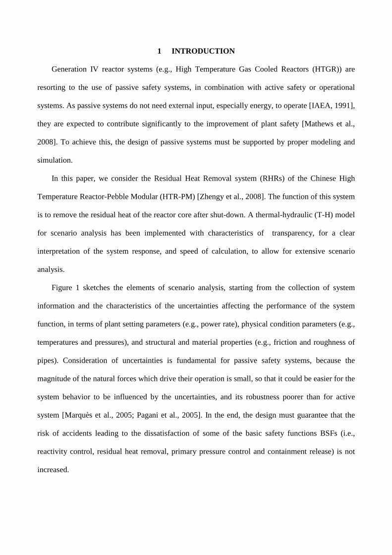
Figure 1 sketches the elements of scenario analysis, starting from the collection of system
information and the characteristics of the uncertainties affecting the performance of the system
function, in terms of plant setting parameters (e.g., power rate), physical condition parameters (e.g.,
temperatures and pressures), and structural and material properties (e.g., friction and roughness of
pipes). Consideration of uncertainties is fundamental for passive safety systems, because the
magnitude of the natural forces which drive their operation is small, so that it could be easier for the
system behavior to be influenced by the uncertainties, and its robustness poorer than for active
system [Marquès et al., 2005; Pagani et al., 2005]. In the end, the design must guarantee that the
risk of accidents leading to the dissatisfaction of some of the basic safety functions BSFs (i.e.,
reactivity control, residual heat removal, primary pressure control and containment release) is not
increased.
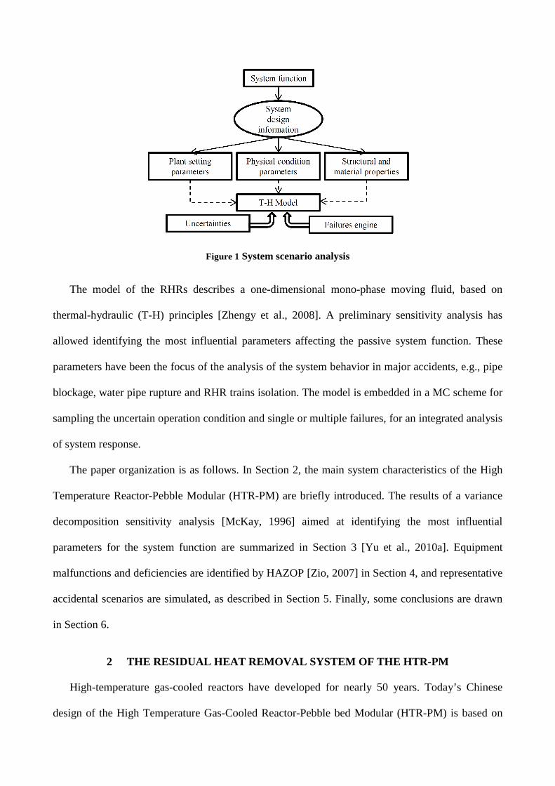
Figure 1 System scenario analysis
The model of the RHRs describes a one-dimensional mono-phase moving fluid, based on
thermal-hydraulic (T-H) principles [Zhengy et al., 2008]. A preliminary sensitivity analysis has
allowed identifying the most influential parameters affecting the passive system function. These
parameters have been the focus of the analysis of the system behavior in major accidents, e.g., pipe
blockage, water pipe rupture and RHR trains isolation. The model is embedded in a MC scheme for
sampling the uncertain operation condition and single or multiple failures, for an integrated analysis
of system response.
The paper organization is as follows. In Section 2, the main system characteristics of the High
Temperature Reactor-Pebble Modular (HTR-PM) are briefly introduced. The results of a variance
decomposition sensitivity analysis [McKay, 1996] aimed at identifying the most influential
parameters for the system function are summarized in Section 3 [Yu et al., 2010a]. Equipment
malfunctions and deficiencies are identified by HAZOP [Zio, 2007] in Section 4, and representative
accidental scenarios are simulated, as described in Section 5. Finally, some conclusions are drawn
in Section 6.
2 THE RESIDUAL HEAT REMOVAL SYSTEM OF THE HTR-PM
High-temperature gas-cooled reactors have developed for nearly 50 years. Today’s Chinese
design of the High Temperature Gas-Cooled Reactor-Pebble bed Modular (HTR-PM) is based on
the technology and experiences of the HTR-10 10MW high-temperature gas-cooled test reactor
(HTR-10) designed in China in 2000.
In Figure 2, a sketch of the HTR-PM layout is shown. At a first glance, the HTR-PM design has
the following key technical features [Zhengy et al., 2008]:
• Uranium dioxide (UO2) fuel kernel coated by tri-isotropic (TRISO) ceramics such as
pyrolytic carbon and silicon carbide (SiC), in order to retain fission products in the particle
under a fuel cladding temperature of 1600ºC in accident cases.
• A one-zone core design is implemented, consisting of approximately 420,000 spherical fuel
elements in a pebble-bed with a diameter of 3m and an average height of 11m, that are
charged and discharged in a so-called “multi-pass” mode, which means that before the fuel
elements reach the discharge burn-up, they go through the reactor core several times.
• Decay heat in the fuel elements is dissipated by means of heat conduction and radiation to
the outside of the reactor pressure vessel, and then taken away to the ultimate heat sink, i.e.,
the passive RHRs, by water cooling panels on the surface of the primary concrete cell.
Therefore, no coolant flow through the reactor core is necessary for decay heat removal in
case of loss of coolant flow or loss of pressure accidents.
Figure 2 Sketch of HTR-PM

Figure 3 sketches the equipment layout of one of the 3 trains of the RHR system implemented in
the HTR-PM: this passive safety system is composed of three circuits dedicated to heat removal,
each one being connected to a loop in the primary circuit. The model capability is evaluated
according to the maximum outlet of water cooling temperature ,w outT reached during the T-H
transient; this is the safety parameter with respect to which the success or failure of the system
function is defined. In fact, from the engineering experience, when ,w outT exceeds the critical
temperature 126cT = [°C] (if 0.3wP = [bar]), local boiling may occur which can significantly
worsen thermal transmission, driving the system into severe damage failure.
Figure 3 Schematics of 1 train of the RHRs in the HTR-PM [Zhao et al., 2008]
Legend: 1) Reactor 2) Vessel 3) Water cooling wall 4) Hot water header 5) Cold water header 6) Shade 7) Hot leg 8) Cold leg 9) Water tank 10) Air cooler 11) Air cooling tower 12) Inlet shutter 13) Outlet shutter 14) Inlet silk net 15) Outlet silk net 16) Wind shield
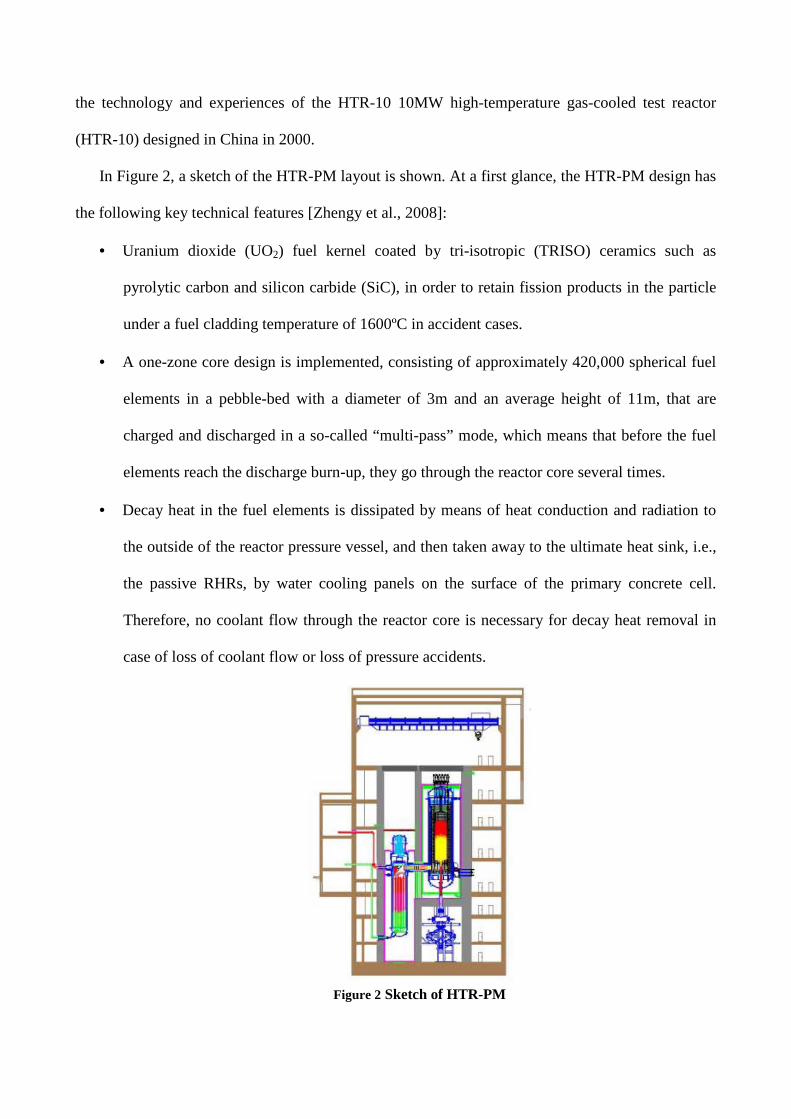
A one-dimensional mono-phase description of the thermo-hydraulic behavior of the RHRs has
been implemented in an iterative MATLAB routine and used to simulate normal operation and
accidental transients. In negligible computational time (compared to the time constants of system
dynamics), the model allows the calculation of ,w outT .
The T-H code models the following steps of the process:
1. The residual heat radiates from the reactor vessel and other thermal sources to the water in the
water-cooling wall;
2. Because of the difference in temperature, natural convection initiates through water, in the
water-cooling wall and pipes connected with the air-cooling heat exchanger; then, heat is
transferred to the water side of the heat exchanger;
3. The heat is transferred by thermal conduction from the water side to the air side of the heat
exchanger, due to the difference of temperature;
4. As the air-cooling heat exchanger is located in the air-cooling tower, natural convection of air
sets up and takes heat to the final heat trap–atmosphere.
Table 1 reports the 37 parameters identified as most influential for the system function, by expert
judgment. To account for the associated uncertainties, these are described by probability
distributions defined on the basis of previous experience and/or information obtained by skilled
experts.
N Parameter Distribution Note 1 W / Residual heat power 2 Ta,in Seasonal/Daily Temperature of inlet air in the air cooled tower 3 xi1 Uniform Resistance coefficient of elbow 4 xi2 Uniform Resistance coefficient of header channel 5 xiw Uniform Resistance coefficient of the water tank walls 6 xia,in Uniform Sum of the resistance coefficients of inlet shutter and air cooling tower and silk net 7 xia,out Uniform Sum of the resistance coefficients of outlet shutter and air cooling tower and silk net 8 xia,narrow Uniform Resistance coefficient of the narrowest part of the tower 9 Pa,in Seasonal/Daily Pressure of the inlet air in the cooler tower 10 dx Uniform Roughness of pipes 11 Ha Normal Height of chimney 12 La Normal Length of pipes in the exchanger 13 Na Normal Total number of pipes in the air cooler 14 Af Normal Air flow crossing are in the narrowest part of the tower 15 Af,in Normal Inlet air flow crossing area in the tower 16 Af,out Normal Outlet air flow crossing area from the tower 17 Af,narrow Normal Crossing area in the narrowest part of the tower 18 S1 Normal Distance between centers of adjacent pipes in horizontal direction 19 S2 Normal Distance between centers of adjacent pipes in vertical direction 20 S Normal Distance between fins in the ribbed pipe 21 Da Normal Pipes inner diameter in the air cooling exchanger 22 Do Normal Pipes outer diameter 23 Douter Normal Rib outer diameter
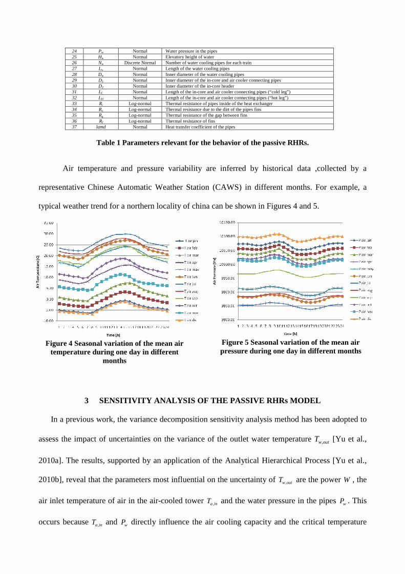
24 Pw Normal Water pressure in the pipes 25 Hw Normal Elevatory height of water 26 Nw Discrete Normal Number of water cooling pipes for each train 27 Lw Normal Length of the water cooling pipes 28 Dw Normal Inner diameter of the water cooling pipes 29 D1 Normal Inner diameter of the in-core and air cooler connecting pipes 30 D2 Normal Inner diameter of the in-core header 31 LC Normal Length of the in-core and air cooler connecting pipes (“cold leg”) 32 LH Normal Length of the in-core and air cooler connecting pipes (“hot leg”) 33 Ri Log-normal Thermal resistance of pipes inside of the heat exchanger 34 Ro Log-normal Thermal resistance due to the dirt of the pipes fins 35 Rg Log-normal Thermal resistance of the gap between fins 36 Rf Log-normal Thermal resistance of fins 37 lamd Normal Heat transfer coefficient of the pipes
Table 1 Parameters relevant for the behavior of the passive RHRs.
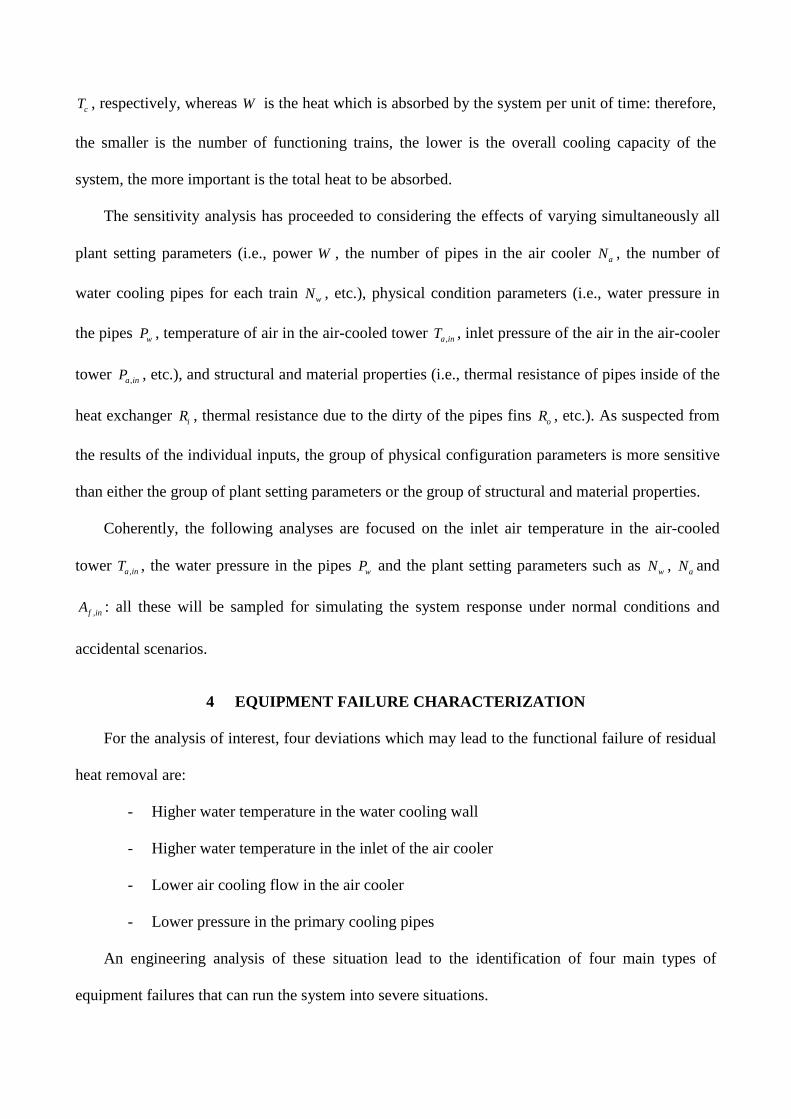
Air temperature and pressure variability are inferred by historical data ,collected by a
representative Chinese Automatic Weather Station (CAWS) in different months. For example, a
typical weather trend for a northern locality of china can be shown in Figures 4 and 5.
Figure 4 Seasonal variation of the mean air
temperature during one day in different months
Figure 5 Seasonal variation of the mean air pressure during one day in different months
3 SENSITIVITY ANALYSIS OF THE PASSIVE RHRs MODEL
In a previous work, the variance decomposition sensitivity analysis method has been adopted to
assess the impact of uncertainties on the variance of the outlet water temperature ,w outT [Yu et al.,
2010a]. The results, supported by an application of the Analytical Hierarchical Process [Yu et al.,
2010b], reveal that the parameters most influential on the uncertainty of ,w outT are the power W , the
air inlet temperature of air in the air-cooled tower ,a inT and the water pressure in the pipes wP . This
occurs because ,a inT and wP directly influence the air cooling capacity and the critical temperature
cT , respectively, whereas W is the heat which is absorbed by the system per unit of time: therefore,
the smaller is the number of functioning trains, the lower is the overall cooling capacity of the
system, the more important is the total heat to be absorbed.
The sensitivity analysis has proceeded to considering the effects of varying simultaneously all
plant setting parameters (i.e., power W , the number of pipes in the air cooler aN , the number of
water cooling pipes for each train wN , etc.), physical condition parameters (i.e., water pressure in
the pipes wP , temperature of air in the air-cooled tower ,a inT , inlet pressure of the air in the air-cooler
tower ,a inP , etc.), and structural and material properties (i.e., thermal resistance of pipes inside of the
heat exchanger iR , thermal resistance due to the dirty of the pipes fins oR , etc.). As suspected from
the results of the individual inputs, the group of physical configuration parameters is more sensitive
than either the group of plant setting parameters or the group of structural and material properties.
Coherently, the following analyses are focused on the inlet air temperature in the air-cooled
tower ,a inT , the water pressure in the pipes wP and the plant setting parameters such as wN , aN and
,f inA : all these will be sampled for simulating the system response under normal conditions and
accidental scenarios.
4 EQUIPMENT FAILURE CHARACTERIZATION
For the analysis of interest, four deviations which may lead to the functional failure of residual
heat removal are:
- Higher water temperature in the water cooling wall
- Higher water temperature in the inlet of the air cooler
- Lower air cooling flow in the air cooler
- Lower pressure in the primary cooling pipes
An engineering analysis of these situation lead to the identification of four main types of
equipment failures that can run the system into severe situations.
- Reduction of the number of air cooling pipes (Na), i.e, pipe blockage
- Reduction of the number of water cooling wall pipes (Nw), i.e, water pipe rupture
- The inlet shutters fails partially close, so that Af,in is smaller
- One of the three trains is isolated for some reason, e.g. maintenance
5 SIMULATION OF ACCIDENTAL SCENARIOS
In this Section, the outcomes of the sensitivity and engineering analyses are exploited to define
the simulation of a number of accidental scenarios. The calculations have been run with the system
at power 1200W = [kW] and water pressure in the pipes 0.3wP = [bar], under sampled conditions of
the variables initial inlet air temperature and initial air pressure in the air-cooled tower, ,a inT and
,a inP , respectively [Yu et al, 2010a; Yu et al., 2010b].
A Monte Carlo (MC) sampling procedure has been developed for injecting equipment faults at
random times and of random magnitudes in the RHRs. The set of faults considered are:
• A random number of air pipes in the air cooler (10) for train 1/2/3 fails stuck/broken at time
t1/2/3 in [1,2880] [min], so that the total number of pipes in each air cooler is equal to 1/ 2 /3aN .
• The inlet shutter (12) of the air cooling tower (11) for train 1/2/3 fails stuck at time t4/5/6 in
[1,2880] [min], providing a corresponding air flow crossing area 1/ 2 /3,f inA in each tower.
• A random number of water cooling pipes (3) for train 1/2/3 fails stuck/broken at time t7/8/9 in
[1,2880] [min], so that the total number of pipes in each air cooler 1/ 2 /3wN .
• One of the three trains is unavailable at time t10 in [1,2880] [min].
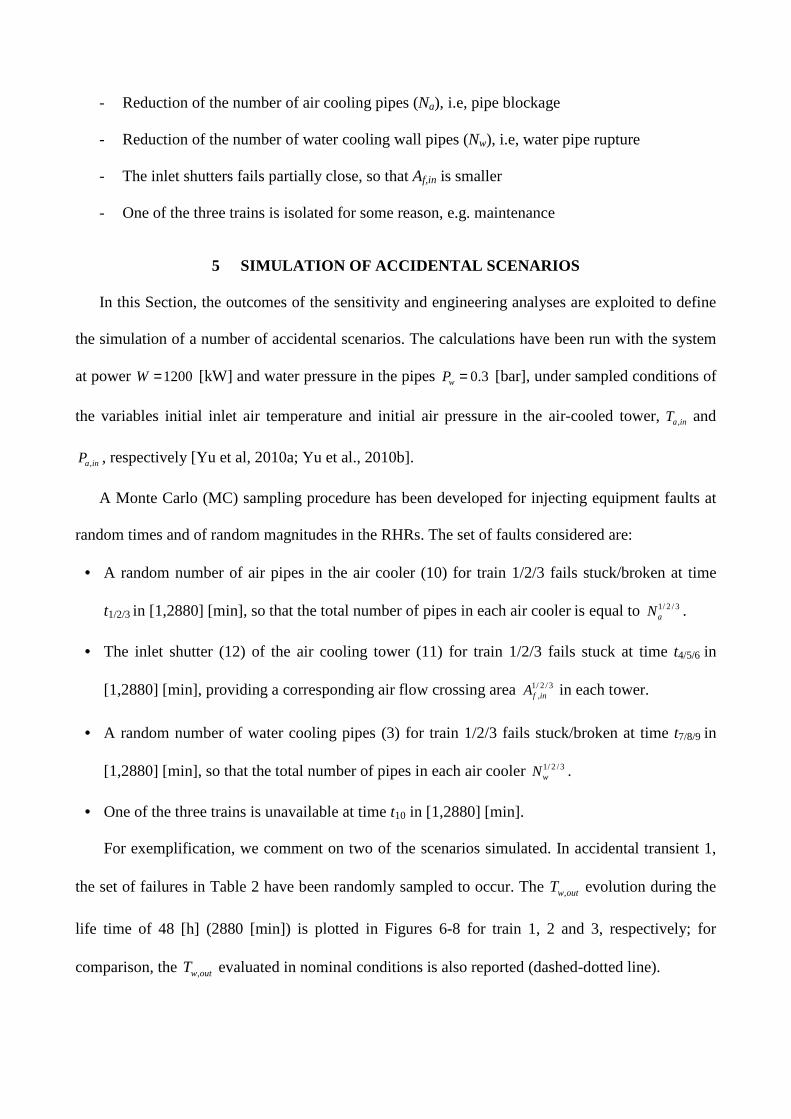
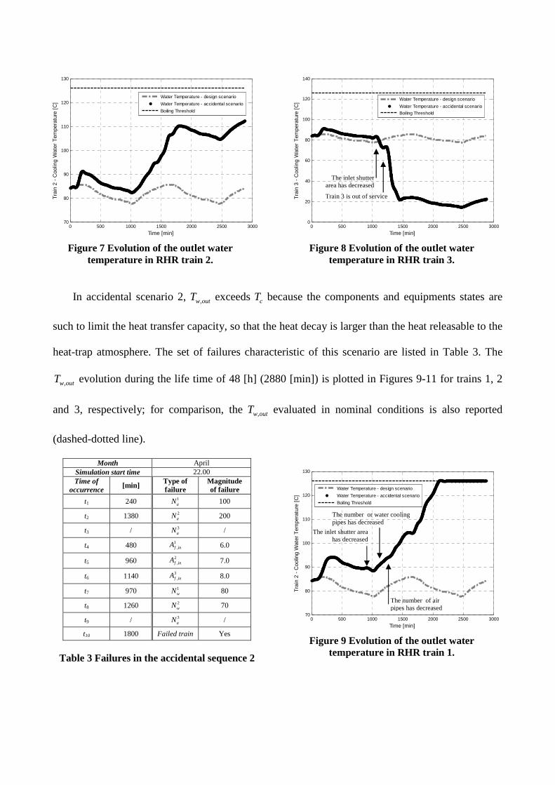
For exemplification, we comment on two of the scenarios simulated. In accidental transient 1,
the set of failures in Table 2 have been randomly sampled to occur. The ,w outT evolution during the
life time of 48 [h] (2880 [min]) is plotted in Figures 6-8 for train 1, 2 and 3, respectively; for
comparison, the ,w outT evaluated in nominal conditions is also reported (dashed-dotted line).
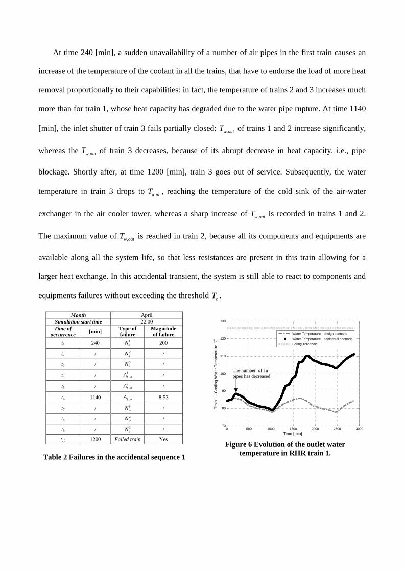
At time 240 [min], a sudden unavailability of a number of air pipes in the first train causes an
increase of the temperature of the coolant in all the trains, that have to endorse the load of more heat
removal proportionally to their capabilities: in fact, the temperature of trains 2 and 3 increases much
more than for train 1, whose heat capacity has degraded due to the water pipe rupture. At time 1140
[min], the inlet shutter of train 3 fails partially closed: ,w outT of trains 1 and 2 increase significantly,
whereas the ,w outT of train 3 decreases, because of its abrupt decrease in heat capacity, i.e., pipe
blockage. Shortly after, at time 1200 [min], train 3 goes out of service. Subsequently, the water
temperature in train 3 drops to ,a inT , reaching the temperature of the cold sink of the air-water
exchanger in the air cooler tower, whereas a sharp increase of ,w outT is recorded in trains 1 and 2.
The maximum value of ,w outT is reached in train 2, because all its components and equipments are
available along all the system life, so that less resistances are present in this train allowing for a
larger heat exchange. In this accidental transient, the system is still able to react to components and
equipments failures without exceeding the threshold cT .
Month April Simulation start time 22.00 Time of
occurrence [min] Type of
failure Magnitude of failure
t1 240 1aN 200
t2 / 2aN /
t3 / 3aN /
t4 / 1,f inA /
t5 / 2,f inA /
t6 1140 3,f inA 8.53
t7 / 1wN /
t8 / 2wN /
t9 / 3aN /
t10 1200 Failed train Yes
Table 2 Failures in the accidental sequence 1
0 500 1000 1500 2000 2500 300070
80
90
100
110
120
130
Time [min]
Tra
in 1
- C
oolin
g W
ater
Tem
pera
ture
[C
]
Water Temperature - design scenario
Water Temperature - accidental scenario
Boiling Threshold
Figure 6 Evolution of the outlet water temperature in RHR train 1.
The number of air pipes has decreased
0 500 1000 1500 2000 2500 300070
80
90
100
110
120
130
Time [min]
Tra
in 2
- C
oolin
g W
ater
Tem
pera
ture
[C
]
Water Temperature - design scenario
Water Temperature - accidental scenario
Boiling Threshold
Figure 7 Evolution of the outlet water
temperature in RHR train 2.
0 500 1000 1500 2000 2500 30000
20
40
60
80
100
120
140
Time [min]
Tra
in 3
- C
oolin
g W
ater
Tem
pera
ture
[C
]
Water Temperature - design scenario
Water Temperature - accidental scenario
Boiling Threshold
Figure 8 Evolution of the outlet water temperature in RHR train 3.
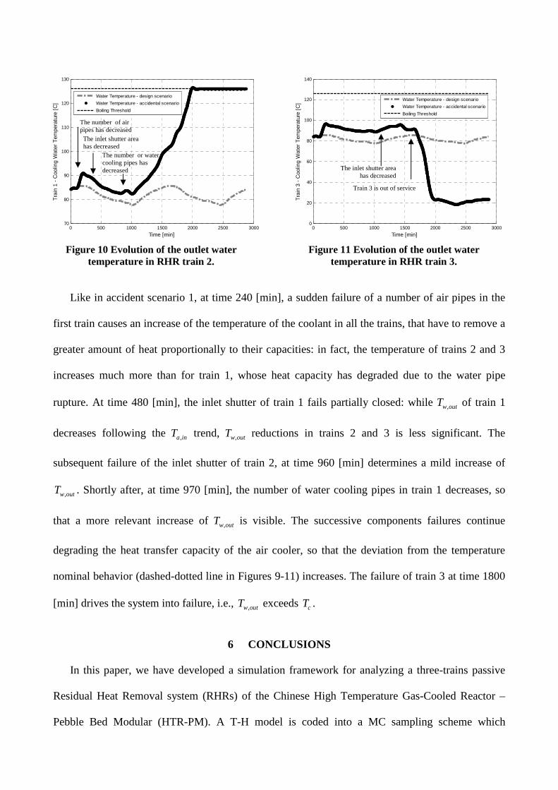
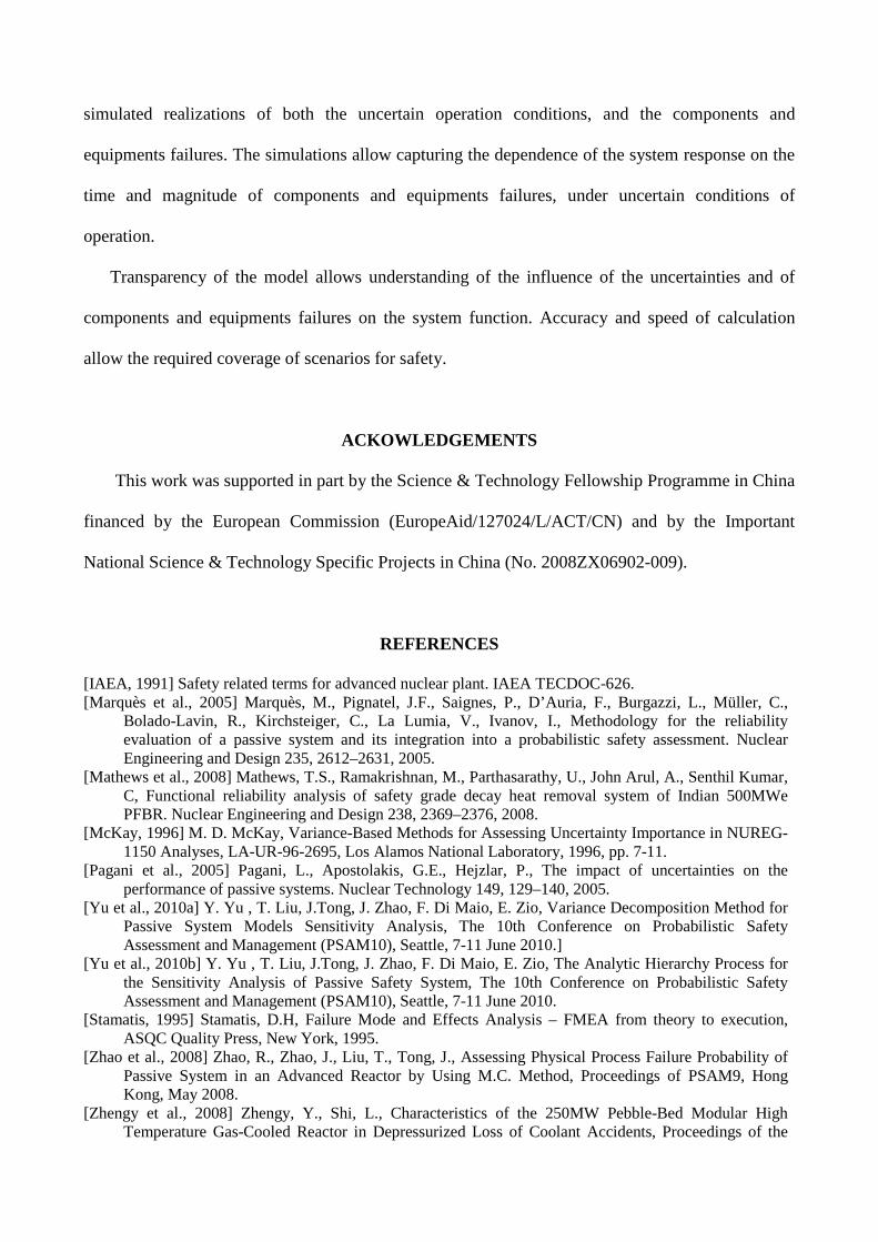
In accidental scenario 2, ,w outT exceeds cT because the components and equipments states are
such to limit the heat transfer capacity, so that the heat decay is larger than the heat releasable to the
heat-trap atmosphere. The set of failures characteristic of this scenario are listed in Table 3. The
,w outT evolution during the life time of 48 [h] (2880 [min]) is plotted in Figures 9-11 for trains 1, 2
and 3, respectively; for comparison, the ,w outT evaluated in nominal conditions is also reported
(dashed-dotted line).
Month April Simulation start time 22.00 Time of
occurrence [min] Type of
failure Magnitude of failure
t1 240 1aN 100
t2 1380 2aN 200
t3 / 3aN /
t4 480 1,f inA 6.0
t5 960 2,f inA 7.0
t6 1140 3,f inA 8.0
t7 970 1wN 80
t8 1260 2wN 70
t9 / 3aN /
t10 1800 Failed train Yes
Table 3 Failures in the accidental sequence 2
0 500 1000 1500 2000 2500 300070
80
90
100
110
120
130
Time [min]
Tra
in 2
- C
oolin
g W
ater
Tem
pera
ture
[C
]
Water Temperature - design scenario
Water Temperature - accidental scenario
Boiling Threshold
Figure 9 Evolution of the outlet water temperature in RHR train 1.
The inlet shutter area has decreased
Train 3 is out of service
The number of air pipes has decreased
The inlet shutter area has decreased
The number or water cooling pipes has decreased
0 500 1000 1500 2000 2500 300070
80
90
100
110
120
130
Time [min]
Tra
in 1
- C
oolin
g W
ater
Tem
pera
ture
[C
]
Water Temperature - design scenario
Water Temperature - accidental scenario
Boiling Threshold
Figure 10 Evolution of the outlet water
temperature in RHR train 2.
0 500 1000 1500 2000 2500 30000
20
40
60
80
100
120
140
Time [min]
Tra
in 3
- C
oolin
g W
ater
Tem
pera
ture
[C
]
Water Temperature - design scenario
Water Temperature - accidental scenario
Boiling Threshold
Figure 11 Evolution of the outlet water temperature in RHR train 3.
Like in accident scenario 1, at time 240 [min], a sudden failure of a number of air pipes in the
first train causes an increase of the temperature of the coolant in all the trains, that have to remove a
greater amount of heat proportionally to their capacities: in fact, the temperature of trains 2 and 3
increases much more than for train 1, whose heat capacity has degraded due to the water pipe
rupture. At time 480 [min], the inlet shutter of train 1 fails partially closed: while ,w outT of train 1
decreases following the ,a inT trend, ,w outT reductions in trains 2 and 3 is less significant. The
subsequent failure of the inlet shutter of train 2, at time 960 [min] determines a mild increase of
,w outT . Shortly after, at time 970 [min], the number of water cooling pipes in train 1 decreases, so
that a more relevant increase of ,w outT is visible. The successive components failures continue
degrading the heat transfer capacity of the air cooler, so that the deviation from the temperature
nominal behavior (dashed-dotted line in Figures 9-11) increases. The failure of train 3 at time 1800
[min] drives the system into failure, i.e., ,w outT exceeds cT .
6 CONCLUSIONS
In this paper, we have developed a simulation framework for analyzing a three-trains passive
Residual Heat Removal system (RHRs) of the Chinese High Temperature Gas-Cooled Reactor –
Pebble Bed Modular (HTR-PM). A T-H model is coded into a MC sampling scheme which
The number of air pipes has decreased The inlet shutter area has decreased
The number or water cooling pipes has decreased
Train 3 is out of service
The inlet shutter area has decreased
simulated realizations of both the uncertain operation conditions, and the components and
equipments failures. The simulations allow capturing the dependence of the system response on the
time and magnitude of components and equipments failures, under uncertain conditions of
operation.
Transparency of the model allows understanding of the influence of the uncertainties and of
components and equipments failures on the system function. Accuracy and speed of calculation
allow the required coverage of scenarios for safety.
ACKOWLEDGEMENTS
This work was supported in part by the Science & Technology Fellowship Programme in China
financed by the European Commission (EuropeAid/127024/L/ACT/CN) and by the Important
National Science & Technology Specific Projects in China (No. 2008ZX06902-009).
REFERENCES
[IAEA, 1991] Safety related terms for advanced nuclear plant. IAEA TECDOC-626. [Marquès et al., 2005] Marquès, M., Pignatel, J.F., Saignes, P., D’Auria, F., Burgazzi, L., Müller, C.,
Bolado-Lavin, R., Kirchsteiger, C., La Lumia, V., Ivanov, I., Methodology for the reliability evaluation of a passive system and its integration into a probabilistic safety assessment. Nuclear Engineering and Design 235, 2612–2631, 2005.
[Mathews et al., 2008] Mathews, T.S., Ramakrishnan, M., Parthasarathy, U., John Arul, A., Senthil Kumar, C, Functional reliability analysis of safety grade decay heat removal system of Indian 500MWe PFBR. Nuclear Engineering and Design 238, 2369–2376, 2008.
[McKay, 1996] M. D. McKay, Variance-Based Methods for Assessing Uncertainty Importance in NUREG-1150 Analyses, LA-UR-96-2695, Los Alamos National Laboratory, 1996, pp. 7-11.
[Pagani et al., 2005] Pagani, L., Apostolakis, G.E., Hejzlar, P., The impact of uncertainties on the performance of passive systems. Nuclear Technology 149, 129–140, 2005.
[Yu et al., 2010a] Y. Yu , T. Liu, J.Tong, J. Zhao, F. Di Maio, E. Zio, Variance Decomposition Method for Passive System Models Sensitivity Analysis, The 10th Conference on Probabilistic Safety Assessment and Management (PSAM10), Seattle, 7-11 June 2010.]
[Yu et al., 2010b] Y. Yu , T. Liu, J.Tong, J. Zhao, F. Di Maio, E. Zio, The Analytic Hierarchy Process for the Sensitivity Analysis of Passive Safety System, The 10th Conference on Probabilistic Safety Assessment and Management (PSAM10), Seattle, 7-11 June 2010.
[Stamatis, 1995] Stamatis, D.H, Failure Mode and Effects Analysis – FMEA from theory to execution, ASQC Quality Press, New York, 1995.
[Zhao et al., 2008] Zhao, R., Zhao, J., Liu, T., Tong, J., Assessing Physical Process Failure Probability of Passive System in an Advanced Reactor by Using M.C. Method, Proceedings of PSAM9, Hong Kong, May 2008.
[Zhengy et al., 2008] Zhengy, Y., Shi, L., Characteristics of the 250MW Pebble-Bed Modular High Temperature Gas-Cooled Reactor in Depressurized Loss of Coolant Accidents, Proceedings of the

fourth international topical meeting on high temperature reactor technology, HTR2008, Washington, DC, USA: 2008.
[Zio, 2007] Zio, E., n Introduction to the Basics of Reliability and Risk Analysis, Series on Quality, Reliability and Engineering Statistics, Vol. 13, World Scientific Publishing Company, 2007.