Embed Size (px)
Citation preview

Patches & Effects Guide
This is a hypertext-enabled document. All references to page numbers are live links. Just click on the page number, and the document will go there automatically!

Eng
lish
The FCC Caution
This device complies with Part15 of the FCC Rules. Operation is subject to the following two conditions: (1) This device may not cause harmful interference, and (2) this device must accept any interference received, including interference that may cause undesired operation.
The FCC Regulation Warning
This equipment has been tested and found to comply with the limits for a ClassB digital device, pursuant to Part 15 of the FCC Rules. These limits are designed to provide reasonable protection against harmful interference in a residential installation. This equipment generates, uses, and can radiate radio frequency energy and, if not installed and used in accordance with the instructions, may cause harmful interference to radio communications. However, there is no guarantee that interference will not occur in a particular installation. If this equipment does cause harmful interference to radio or television reception, which can be determined by turning the equipment off and on, the user is encouraged to try to correct the interference by one or more of the following measures:
- Reorient or relocate the receiving antenna.
- Increase the separation between the equipment and receiver.
- Connect the equipment into an outlet on a circuit different from that to which the receiver is connected.
- Consult the dealer or an experienced radio/TV technician for help.
Unauthorized changes or modification to this system can void the user's authority to operate this equipment.
Canada
This Class B digital apparatus complies with Canadian ICES-003.
Cet appareil numerique de la classe B est conforme a la norme NMB-003 du Canada.
CE mark for European Harmonized Standards
CE mark which is attached to our company’s products of AC mains operated apparatus until December 31, 1996 means it conforms to EMC Directive (89/336/EEC) and CE mark Directive (93/68/EEC).
And, CE mark which is attached after January 1, 1997 means it conforms to EMC Directive (89/336/EEC), CE mark Directive (93/68/EEC), and Low Voltage Directive (73/23/EEC).
Also, CE mark which is attached to our company’s products of battery operated apparatus means it conforms to EMC Directive (89/336/EEC) and CE mark Directive (93/68/EEC).
Trademarks
ADAT, ADAT XT, and BRC are registered trademarks of Alesis, Inc.; RD-8 and CX-8 are registered trademarks of the Fostex, Inc.; MDA-1 is a registered trademark of Panasonic, Inc; Apple and MacOS are registered trademarks of Apple Computer, Inc.; Windows 95 and Windows 98 are registered trademarks of Microsoft Corp. All other company names, brand names, product names, and names of formats etc. are the trademarks or registered trademarks of their respective owners.
Licensor Indications
This product was developed by practicing physical modeling tone generator patents (listed in http://www.sondius-xg.com) owned by Stanford University USA and Yamaha Corporation. The rights to use these patents were provided under license from STACCATO Systems Inc. (www.STACCATOsys.com)
Third-Party Products
Mention of third-party products is for informational purposes only and constitutes neither an endorsement nor a recommendation. Korg assumes no responsibility with regard to the performance or use of these products.
Manual Version: 7/23/01
Copyright 1999-2001 Korg Inc. All rights reserved.
Onscreen graphics by GAS Brand Design.
KORG INC.
Tested to comply with FCC Standards
FOR HOME OR OFFICE USE
OASYS PCI
ii OASYS PCI

Contents
General Information............................................................... 1Modulation Sources ..............................................................................................................2MIDI Tempo LFOs ................................................................................................................5
Patches..................................................................................... 7
Analog Synths.......................................................................... 8Analog 1 Osc ..........................................................................................................................9Analog 2 Osc ........................................................................................................................14Analog Bass-Lead ................................................................................................................22Comb Synth ..........................................................................................................................28KB-303 ...................................................................................................................................35Mini Synth .............................................................................................................................38Noise Synth ..........................................................................................................................44Pro Synth ...............................................................................................................................50Pro Synth Mod .....................................................................................................................57
EP (Electric Piano)................................................................ 66Reed Piano ............................................................................................................................67
Guitar ..................................................................................... 69Plucked String ......................................................................................................................70Small Plucked String ............................................................................................................75Slap Bass ................................................................................................................................79Small Slap Bass .....................................................................................................................83
Organ ..................................................................................... 85Tonewheel Organ ...............................................................................................................86Z1 Organ ..............................................................................................................................89
PCM........................................................................................ 94PCM Patches Overview .....................................................................................................95Argon 4+ ...............................................................................................................................96Cobalt 2 .............................................................................................................................. 106Cobalt 2 St ......................................................................................................................... 111Cobalt 4 .............................................................................................................................. 116Cobalt 4+ ........................................................................................................................... 121Krypton 2 ........................................................................................................................... 126Krypton 2e ......................................................................................................................... 129Krypton 2p ........................................................................................................................ 134Looper ................................................................................................................................ 138Looper St ........................................................................................................................... 140Looper X ............................................................................................................................ 142
OASYS PCI iii

Eng
lish
Xenon 2 .............................................................................................................................. 144Xenon 2i ............................................................................................................................. 153Xenon 4 .............................................................................................................................. 162Xenon 4+ ........................................................................................................................... 171Xenon 4m .......................................................................................................................... 180
Percussion............................................................................ 190Percussion Synth .............................................................................................................. 191Percussion Synth 2 ........................................................................................................... 193Beat Box ............................................................................................................................. 196
VPM ...................................................................................... 199VPM 2 OP .......................................................................................................................... 200VPM 4 OP .......................................................................................................................... 204VPM 4 OP Select .............................................................................................................. 209VPM 4 OP Stack ............................................................................................................... 213
Waveguide ........................................................................... 218Flute ..................................................................................................................................... 219Tenor Sax ........................................................................................................................... 223Trombone .......................................................................................................................... 227Trumpet ............................................................................................................................. 231Vocal .................................................................................................................................... 235
Effects ................................................................................... 241
Amp & Speaker ................................................................... 242Guitar Amp ........................................................................................................................ 243St Guitar Amp ................................................................................................................... 244
Chorus .................................................................................. 2454-Tap Chorus .................................................................................................................... 2466-Tap Chorus .................................................................................................................... 248Chorus ................................................................................................................................ 251EQ Chorus ......................................................................................................................... 253Harmonic Chorus ............................................................................................................ 255St 2-Band Chor ................................................................................................................. 257St Bi-Phase Chr ................................................................................................................. 260St Chorus ........................................................................................................................... 263St EQ Chorus .................................................................................................................... 265St HarmonicChr ............................................................................................................... 268St Step Chorus .................................................................................................................. 271St Step Chor 2 .................................................................................................................. 274St TempoChorus .............................................................................................................. 277Tempo Chorus ................................................................................................................. 281
Compressor & Gate............................................................ 284Compressor ...................................................................................................................... 285
iv OASYS PCI

Dual MIDI Gate ................................................................................................................ 287Expander Gate .................................................................................................................. 289Limiter ................................................................................................................................ 292MIDI Gate .......................................................................................................................... 294St Compressor ................................................................................................................. 296St Expander Gate ............................................................................................................. 298St Limiter ............................................................................................................................ 301
Delay..................................................................................... 3033Tap Delay A .................................................................................................................... 3043Tap MidiDly ..................................................................................................................... 30740Sec MidiDly ................................................................................................................... 310Delay Mod Long ............................................................................................................... 313Delay Mod ......................................................................................................................... 315Delay ................................................................................................................................... 317Diffuse Delay ..................................................................................................................... 319Dual Delay ......................................................................................................................... 323L-C-R Delay ....................................................................................................................... 325L-C-R Dly Long ................................................................................................................. 328Midi Delay .......................................................................................................................... 331Multitap Delay ................................................................................................................... 334St Delay Long .................................................................................................................... 336St Delay .............................................................................................................................. 338St Diffuse Dly .................................................................................................................... 340St Dynamic Dly ................................................................................................................. 344St Midi Dly ......................................................................................................................... 347St Mod Delay ..................................................................................................................... 350St Multitap Dly .................................................................................................................. 353
Distortion............................................................................. 356Hyper-Gain Wah .............................................................................................................. 357Hyper-Gain ........................................................................................................................ 360Overdrive Wah ................................................................................................................ 363Overdrive ........................................................................................................................... 366
Ensemble.............................................................................. 369Ensemble ............................................................................................................................ 370St Ensemble ....................................................................................................................... 372
Early Reflections.................................................................. 374Early Reflections Long ..................................................................................................... 375Early Reflections ............................................................................................................... 377
EQ......................................................................................... 3793-Band EQ ......................................................................................................................... 3803-Parametric ...................................................................................................................... 3835-Band EQ ......................................................................................................................... 385
OASYS PCI v

Eng
lish
Graphic EQ 10 .................................................................................................................. 388Graphic EQ 7 .................................................................................................................... 390High Cut Filter .................................................................................................................. 392High-Low Shelf .................................................................................................................. 393Low Cut Filter ................................................................................................................... 395St 3-Band EQ ..................................................................................................................... 396St 5-Band EQ ..................................................................................................................... 398St Graphic EQ10 .............................................................................................................. 401St Hi-Lo Shelf .................................................................................................................... 403St HighCut Filter .............................................................................................................. 405St LowCut Filter ............................................................................................................... 406
Filters.................................................................................... 407Auto Wah .......................................................................................................................... 408Dyna Exciter ...................................................................................................................... 411Mini Filter ........................................................................................................................... 413Random Filter .................................................................................................................... 417Rez Filter Env .................................................................................................................... 419Rez Filter Lfo ..................................................................................................................... 423Rez Filter Seq .................................................................................................................... 429Rez Filter+Amp ................................................................................................................. 435St Auto Wah ..................................................................................................................... 440Stereo Enhancer ............................................................................................................... 443Talking Mod ....................................................................................................................... 446Wide Stereo ...................................................................................................................... 449
Flangers ................................................................................ 451Envelope Flanger ............................................................................................................... 452Flanger ................................................................................................................................. 454St Env Flanger .................................................................................................................... 456St Flanger ............................................................................................................................ 458St RandomFlange .............................................................................................................. 461St TempoFlanger .............................................................................................................. 464StTempoFlange2 ............................................................................................................... 469Tempo Flanger .................................................................................................................. 476
Modulations ......................................................................... 481Doppler .............................................................................................................................. 482Dual Resonator ................................................................................................................. 484Resonator ........................................................................................................................... 486Ring Modulator ................................................................................................................. 488St Vibrato AF ..................................................................................................................... 491St Vibrato ........................................................................................................................... 494Vibrato AF .......................................................................................................................... 496Vibrato ................................................................................................................................ 500
vi OASYS PCI

Organ FX ............................................................................. 503Rotary Speaker ................................................................................................................. 504Vibrato Chorus ................................................................................................................. 508
Other Effects ....................................................................... 509Decimator .......................................................................................................................... 510LR Gain ............................................................................................................................... 512Piano Body ......................................................................................................................... 513St Decimator ..................................................................................................................... 515St Gain ................................................................................................................................ 516Sub Oscillator ................................................................................................................... 517The Producer .................................................................................................................... 520
Pan & Tremolo.................................................................... 522Shimmer ............................................................................................................................. 523St Auto Pan ........................................................................................................................ 526St Envelope Pan ................................................................................................................ 529St Tempo Pan .................................................................................................................... 532St Tempo Trem ................................................................................................................ 537St Tremolo AF .................................................................................................................. 542StTempoTrem AF ............................................................................................................ 546Tempo Tremolo ............................................................................................................... 552Tremolo ............................................................................................................................. 557
Phasers ................................................................................. 559Envelope Phaser ............................................................................................................... 560Phaser ................................................................................................................................. 562St Env Phaser ..................................................................................................................... 564St Phaser ............................................................................................................................ 566St RandomPhaser ............................................................................................................. 569St TempoPhase2 ............................................................................................................... 572St TempoPhaser ............................................................................................................... 579Tempo Phaser ................................................................................................................... 584Tremolo Phaser ................................................................................................................ 589
Pitch Shifters ....................................................................... 5932Band PitchShift ................................................................................................................ 594Detune ................................................................................................................................ 597Pitch Shift Mod .................................................................................................................. 599Pitch Shifter ....................................................................................................................... 601St Pitch Shifter .................................................................................................................. 603
Reverbs................................................................................. 605Hall Ambience ................................................................................................................... 606Hall Reverb ........................................................................................................................ 608O-Verb ............................................................................................................................... 610O-Verb ER ......................................................................................................................... 613
OASYS PCI vii

Eng
lish
O-Verb LE .......................................................................................................................... 617O-Verb XL ......................................................................................................................... 619Room Ambience ............................................................................................................... 625Room Reverb .................................................................................................................... 627
Index..................................................................................... 629
viii OASYS PCI

General Information

Modulation Sources General Information
Eng
lish
Modulation SourcesYou can modulate any parameter on any Patch or Effect control panel, using any of these MIDI modulation sources. For more information, see the Using Modulation section in the Users Guide.
List of Modulation SourcesNone. No modulation will be applied.
Velocity. MIDI note-on velocity. When modulating Effects, the most recent velocity will be used.
Exp. Velocity. MIDI note-on velocity, through an exponential curve. This creates more variation at high velocities, and less variation at lower velocities. When modulating Effects, the most recent velocity will be used.
Note. MIDI note number. When modulating Effects, the most recent note number will be used.
Note+Pitchbend. This selection adds the Pitch Bend amount to the MIDI note number, for more precise pitch-related modulation. When modulating Effects, the most recent note number will be used.
Exp. Note. MIDI note number, through an exponential curve. This creates more variation from note to note at the high end of the keyboard, and less variation at the low end. At C2, the value is very small; at C7, it is about 90% of maximum. When modulating Effects, the most recent note number will be used.
Exp. Note+Pitchbend. This selection adds the Pitch Bend amount to the exponential MIDI note number, for more precise pitch-related modulation. When modulating Effects, the most recent note number will be used.
Note Gate. This is an on/off mod source. When the key is held down, the modulation is at maximum; when the key is released, the modulation goes to zero. Note Gate is intended for use in Patches, and does not work for modulation of Effects parameters.
Note Gate+Sustain. This adds the Sustain pedal to Note gate. When the key or the Sustain pedal is held down, the modulation is at maximum; when the key or the Sustain pedal is released, the modulation goes to zero. Note Gate+Sustain is intended for use in Patches, and does not work for modulation of Effects parameters.
Any Note Gate. This is a version of Note Gate which will work with both Patches and Effects. As long as any key is held down, the modulation is at maximum; when all keys are released, the modulation goes to zero.
Any Note Gate+Sustain. This adds the sustain pedal to Any Note Gate, and will work with both Patches and Effects. As long as any key or the sustain pedal is held down, the modulation is at maximum; when all keys are released, and the sustain pedal is lifted, the modulation goes to zero.
2 OASYS PCI

General Information Modulation Sources
Mod Wheel. MIDI Modulation Wheel (controller #1).
Aftertouch. MIDI Aftertouch.
Mod Wheel+AT. This is the sum of Mod Wheel and Aftertouch.
Mod Wheel+AT/2. This is similar to Mod Wheel+AT, but the affect of Aftertouch is cut in half.
Pitchbend. This is MIDI Pitchbend, exactly as received, prior to scaling.
Pitchbend Scaled. This is MIDI Pitchbend, as scaled by the Global or Program Pitch Bend parameters.
Sustain. MIDI Sustain Pedal (controller #64).
MIDI A-H. These are the eight assignable MIDI controllers, as set in the MIDI Preferences.
MIDI Tempo. This receives MIDI Clock, for synching delays, LFOs, and other tempo-based effects. In general, the Patch or Effect must be specifically designed for MIDI Tempo in order to obtain meaningful results.
MIDI Start/Stop. This receives MIDI Start/Stop, for controlling analog-style sequencers or other components which can start and stop with an external MIDI sequencer. In general, the Patch or Effect must be specifically designed for MIDI Start/Stop in order to obtain meaningful results.
Keytrack Linear. Linear keyboard tracking, centered on C4. See the graphs below.
Keytrack Exp. Exponential keyboard tracking, centered on C4, for more variation at the extremes of the keyboard. See the graphs below.
Keytrack Log. Logarithmic keyboard tracking, centered on C4, for more variation in the middle of the keyboard. See the graphs below.
Keytrack Left Lin. Linear keyboard tracking below C4, with no modulation above C4. See the graphs below.
Keytrack Left Exp. Exponential keyboard tracking below C4, with no modulation above C4. See the graphs below.
Keytrack Left Log. Logarithmic keyboard tracking below C4, with no modulation above C4. See the graphs below.
Keytrack Right Lin. Linear keyboard tracking above C4, with no modulation below C4. See the graphs below.
Keytrack Right Exp. Exponential keyboard tracking above C4, with no modulation below C4. See the graphs below.
Keytrack Right Log. Logarithmic keyboard tracking above C4, with no modulation below C4. See the graphs below.
OASYS PCI 3

Modulation Sources General Information
Eng
lish
Keyboard Tracking
C4MIDI Note
Valu
e
0
+127
-127A0 C8
C4MIDI Note
Valu
e
0
+127
-127A0 C8C4
MIDI NoteVa
lue
0
+127
-127A0 C8C4
MIDI Note
Valu
e
0
+127
-127A0 C8
C4MIDI Note
Valu
e
0
+127
-127A0 C8 C4
MIDI Note
Valu
e
0
+127
-127A0 C8
C4MIDI Note
Valu
e
0
+127
-127A0 C8 C4
MIDI Note
Valu
e
0
+127
-127A0 C8 C4
MIDI NoteVa
lue
0
+127
-127A0 C8
Linear Exp Log
Left Lin Left Exp Left Log
Right Lin Right Exp Right Log
4 OASYS PCI

General Information MIDI Tempo LFOs
MIDI Tempo LFOsUse the LFO's MIDI Phase Reset
The OASYS PCI’s MIDI-synced LFOs can be triggered via MIDI. This ensures that the LFO starts in phase with the music.You can include one or more triggers in the MIDI sequence, so that the LFO sounds the same every time. To do this:
1. Create a track in the sequence to use specifically for triggering the LFO. Assign it to the same MIDI channel as the Effect or Program that you'll be controlling.
2. In the control panel, assign a mod source for the LFO's Phase Reset.
“Any Note Gate” works well, unless there's also a Program on the same MIDI channel. In that case, select another controller.
3. Enter a single MIDI event in the sequencer at the start of measure 2, using the mod source assigned to Phase Reset (from now on, we'll call this the “phase reset trigger”).
4. Duplicate the phase reset trigger at intervals at downbeats throughout the sequence (such as every 8 bars or so).
This ensures that no matter where you start playback, the LFO will be reset appropriately.
This is somewhat similar to triggering a loop on a sampler.
5. Also, enter the phase reset trigger every time that the time signature changes.
Now, whenever the OASYS PCI receives the phase reset trigger, the LFO will reset to the position set by the Initial Phase parameter.
Note that you can trigger as many different LFOs as you like, using different triggers on different MIDI channels.
Adjust “feel” using the Initial Phase parameterUsing the LFO's Initial Phase parameter, you can start the LFO at any point of its waveform - at the peak, in the trough, at zero, or at any point in between. You can use this to subtly adjust the rhythmic feel of the LFO; this is especially useful for smooth waveforms, such as triangle, sine, and saw up.
You can also set the Initial Phase to 180 to shift the waveform to the offbeat.
Start on measure 2We've found that triggering LFOs on the downbeat of the very first measure may not always work properly (probably because the sequencer sends the MIDI message triggering the phase slightly after the actual downbeat). This can result in
OASYS PCI 5

MIDI Tempo LFOs General Information
Eng
lish
the LFO being out of phase, so that it doesn't sit properly in the groove. To avoid this:
1. Leave a blank measure at the start of the sequence. Start your MIDI data, and send the first LFO trigger, in measure 2.
6 OASYS PCI

Patches
Patches
OASYS PCI 7

Analog Synths
Eng
lish
Analog Synths
8 OASYS PCI

Analog Synths Analog 1 Osc
Analog 1 OscAnalog 1 Osc is a one-oscillator analog synth model, including a 24dB per octave lowpass filter, pulse width modulation, noise generator, filter and amplitude ADSR envelopes, and a routable LFO.
Oscillator
Frequency+/- 24. This sets the coarse tuning of the oscillator over a four-octave range, in half-steps.
WaveformSawtooth, Pulse, Triangle. This selects the shape of the oscillator. If Pulse is selected, the Pulse Width control, below, sets the width of the pulse.
Pulse Width0.0-100.0. This sets the width of the pulse waveform, as a percentage of the full waveform cycle. 50.0 produces a square wave, smaller amounts produce a waveform with a shorter “up” time, and greater amounts produce a waveform with a longer “up” time, as shown below. Pulse width can also be modulated via the LFO.
Pulse Width
Level0-100. This controls the output level of the oscillator. You can use this to balance the level of the oscillator with that of the noise generator.
50% 75% 100%25%0%
OASYS PCI 9

Analog 1 Osc Analog Synths
Eng
lish
Glide
Glide0-100. This sets the glide amount (also known as portamento) for the oscillator, which makes the pitch slide smoothly between notes. At 0, Glide is completely off. At 100, notes will take a long time to glide to the new pitch.
Note that the effects of glide will also vary depending on the Patch’s voice allocation setting, in the Program Edit window. Poly Retrig, Poly Reuse, Mono Legato, and Unison modes are generally the most suitable for use with Glide, but you may find that you like other settings as well.
Noise
Noise0-100. This controls the output level of the noise generator.
Filter
Cutoff0-100. This controls the cutoff frequency of the 24dB per octave lowpass filter. Frequencies above the cutoff are cut, and frequencies below the cutoff are passed through unchanged.
Generally speaking, the lower the cutoff, the darker the sound; the higher the cutoff, the brighter the sound.
Note that the Envelope and Key Track parameters also affect the cutoff frequency.
This control has extra smoothing on the DSP, to ensure zipper-free modulation. If instantaneous modulation is desired (such as modulation via velocity), modulate the Envelope control instead.
Resonance0-100. Resonance emphasizes the frequencies around the cutoff frequency. At 0, there is no emphasis, and frequencies above the cutoff will simply diminish smoothly. At very high settings, the resonance can be heard as a separate, whistling pitch. At medium settings, the resonance will alter the timbre of the filter, but will not usually be heard as a separate pitch.
Envelope0-100. The ADSR envelope can be used to control the filter cutoff frequency, adding to the setting on the Cutoff knob. When Envelope is set to 0, the envelope will have no affect. At +100, the envelope will open the filter all the way at its peak, even if Cutoff is set to 0.
10 OASYS PCI

Analog Synths Analog 1 Osc
Envelope amount affect on cutoff frequency
Key Track+/- 100. This adjusts the filter cutoff in response to incoming MIDI notes, as shown below. Note that you can also modulate any parameter using the “Key Tracking” modulators in the Mod Palette.
Key Tracking
Attack0-100. This sets the attack time of the filter envelope, which controls how long it takes from the moment that the key is pressed until the envelope reaches its peak.
Decay 0-100. This sets the decay time of the filter envelope, which controls how long it takes the envelope to fall to the sustain level after the attack is complete.
Sustain0-100. This sets the sustain level for the filter envelope. After the decay time is complete, the envelope will stay at this level as long as the note is held.
+100
0
Enve
lope
am
ount
E4MIDI Note
Valu
e
0
+100
-100A0 C8
Key Track amount
-100
+100
0
+50
-50
OASYS PCI 11

Analog 1 Osc Analog Synths
Eng
lish
Release0-100. This sets the release time of the filter envelope, which controls how long it takes the envelope to fall to zero after the note is released.
ADSR Envelope
AmplifierThese parameters control an ADSR envelope dedicated to the output volume. For a graphic explaining ADSR envelopes, see the figure “ADSR Envelope,” above.
Attack0-100. This sets the attack time of the amplitude envelope, which controls how long it takes from the moment that the key is pressed until the envelope reaches its peak.
Decay 0-100. This sets the decay time of the amplitude envelope, which controls how long it takes the envelope to fall to the sustain level after the attack is complete.
Sustain0-100. This sets the sustain level for the amplitude envelope. After the decay time is complete, the envelope will stay at this level as long as the note is held.
Release0-100. This sets the release time of the amplitude envelope, which controls how long it takes the envelope to fall to zero after the note is released.
LFO
Frequency0.0-20.0 Hz. This controls the speed of the LFO.
Attack time Decay time Release timeSustain while
SustainLevel
holding note
Enve
lope
Am
ount
12 OASYS PCI

Analog Synths Analog 1 Osc
WaveformSine, Triangle, Saw, Square. This sets the shape of the LFO.
LFO Mod
Oscillator FreqOn, Off. When this is enabled, the LFO will modulate the pitch of the oscillator.
Pulse WidthOn, Off. When this is enabled, the LFO will modulate the oscillator’s pulse width.
Filter CutoffOn, Off. When this is enabled, the LFO will modulate the filter cutoff frequency.
Initial0-100. This sets the initial amount of LFO modulation.
Mod SourceList of Modulation Sources. This sets the modulation source for controlling the LFO amount. For a complete list, please see “Modulation Sources” on page 2.
Mod Amount0-100. This sets the amount by which the mod source affects the LFO amount.
Output
Volume+12 to -123.9dB, -INF. This is the output volume for the Patch.
IMPORTANT: The output volume provides up to 12dB in gain, so that you can get your signals as hot as possible. However, if filter resonance is high, settings above 0dB may cause clipping.
This control has extra smoothing on the DSP, to ensure zipper-free modulation. If you want to modulate the volume instantaneously via velocity, use the Vel Sens control instead.
Vel Sens (Velocity Sensitivity)0-100. This sets the sensitivity of output volume to velocity. A velocity of 127 will always result in the maximum output level, as set by the Volume control; increasing the Vel Sens will decrease the output volume for low velocities.
OASYS PCI 13

Analog 2 Osc Analog Synths
Eng
lish
Analog 2 OscAnalog 2 Osc is a two-oscillator analog synth model, including a 24dB per octave multi-mode, multi-pole filter, pulse width modulation, colored noise generator, ring modulator, filter and amplitude ADSR envelopes, and a routable LFO.
Oscillator 1
Frequency+/- 24. This sets the coarse tuning of the oscillator over a four-octave range, in half-steps.
WaveformSawtooth, Pulse, Triangle. This selects the shape of oscillator 1. If Pulse is selected, the Pulse Width control, below, sets the width of the pulse.
Pulse Width0.0-100.0. This sets the width of the pulse waveform, as a percentage of the full waveform cycle. 50.0 produces a square wave, smaller amounts produce a waveform with a shorter “up” time, and greater amounts produce a waveform with a longer “up” time, as shown below. Pulse width can also be modulated via the LFO.
Pulse Width
Oscillator 2
Frequency+/- 24. This sets the coarse tuning of the oscillator over a four-octave range, in half-steps.
50% 75% 100%25%0%
14 OASYS PCI

Analog Synths Analog 2 Osc
Fine+/- 100. This sets the fine tuning of the oscillator, in cents (1/100 of a semitone).
Key Track+/- 100. This sets the way in which the oscillator’s pitch tracks MIDI notes, centered on E4.
100 is normal tracking, with one octave of MIDI notes resulting in one octave of pitch change. With Key Track set to 50, two octaves of MIDI notes will map to only a single octave of pitch change; at 25, four octaves of MIDI notes will map to a single octave of pitch change, and so on.
Negative Key Track settings flip the keyboard upside down, centered on MIDI note E4. For instance, a setting of -100 means that one octave of MIDI notes up results in one octave down in pitch.
WaveformSawtooth, Pulse, Triangle. This selects the shape of oscillator 2. If Pulse is selected, the Pulse Width control, below, sets the width of the pulse.
Pulse Width0.0-100.0. This sets the width of the pulse waveform, as a percentage of the full waveform cycle. 50.0 produces a square wave, smaller amounts produce a waveform with a shorter “up” time, and greater amounts produce a waveform with a longer “up” time, as shown below. For a diagram, see the figure “Pulse Width,” above. Pulse width can also be modulated via the LFO.
Mixer
Osc 10-100. This controls the output level of oscillator 1. The button to the right of the knob turns the output on and off completely.
Osc 20-100. This controls the output level of oscillator 2. The button to the right of the knob turns the output on and off completely.
Ring Mod0-100. This controls the output level of the ring modulator. The button to the right of the knob turns the output on and off completely.
The ring modulator multiplies the outputs of oscillator 1 and oscillator 2 together, creating a metallic sound. The timbre will change dramatically depending on the difference in pitch between the two oscillators. Oscillator 2’s fine tuning, especially when modulated, can be used to create all sorts of interesting effects. The classic ring modulation sound uses a constant pitch, so you may also want to set Oscillator 2’s key tracking to 0.
OASYS PCI 15

Analog 2 Osc Analog Synths
Eng
lish
Noise0-100. This controls the output level of the noise generator. The button to the right of the knob turns the output on and off completely.
Glide
Glide0-100. This sets the glide amount (also known as portamento) for the oscillator, which makes the pitch slide smoothly between notes. At 0, Glide is completely off. At 100, notes will take a long time to glide to the new pitch.
Note that the effects of glide will also vary depending on the Patch’s voice allocation setting, in the Program Edit window. Poly Retrig, Poly Reuse, Mono Legato, and Unison modes are generally the most suitable for use with Glide, but you may find that you like other settings as well.
Noise Generator
Color0-100. This is the cutoff frequency of a lowpass filter dedicated the noise generator. Lower values will make the noise output darker, as well as more “speckly” and uneven.
Filter
Cutoff0-100. This controls the cutoff frequency of the filter. The meaning of the cutoff frequency will change depending on the filter mode.
When the filter is set to Lowpass mode, frequencies above the cutoff are attenuated, and frequencies below the cutoff are passed through unchanged.
When the filter is set to Highpass mode, frequencies below the cutoff will be attenuated, and frequencies above the cutoff will pass through unchanged.
When the filter is set to Bandpass mode, frequencies both above and below the cutoff will be attenuated, and only frequencies right at the cutoff will pass through unchanged.
Note that the Envelope and Key Track parameters also affect the cutoff frequency.
This control has extra smoothing on the DSP, to ensure zipper-free modulation. If instantaneous modulation is desired (such as modulation via velocity), modulate the Envelope control instead.
Resonance0-100. Resonance emphasizes the frequencies around the cutoff frequency. At 0, there is no emphasis, and frequencies beyond the cutoff will simply diminish smoothly. At very high settings, the resonance can be heard as a separate, whistling
16 OASYS PCI

Analog Synths Analog 2 Osc
pitch. At medium settings, the resonance will alter the timbre of the filter, but will not usually be heard as a separate pitch. The timbre and intensity of the resonance will change depending on the filter Type setting - 4 Pole, 2 Pole, or 2 Pole > 2 Pole.
Envelope+/- 100. The ADSR envelope can be used to control the filter cutoff frequency, adding to or subtracting from the setting on the Cutoff knob. With positive envelope amounts, the envelope will increase the cutoff frequency above the setting on the Cutoff knob. With negative amounts, the envelope will act as if it is inverted, decreasing the cutoff frequency below the setting on the Cutoff knob.
At 0, the envelope will have no affect. At +100, the envelope will open the filter all the way at its peak, even if Cutoff is set to 0. At -100, the envelope will close the filter all the way down at its peak, even if the Cutoff is set to 100.
Envelope amount affect on cutoff frequency
Key Track+/- 100. This adjusts the filter cutoff in response to incoming MIDI notes, centered on E4, as shown below. Note that you can also modulate any parameter using the “Key Tracking” modulators in the Mod Palette.
+100
-100
0
Enve
lope
am
ount
OASYS PCI 17

Analog 2 Osc Analog Synths
Eng
lish
Key Tracking
ModeLowpass, Highpass, Bandpass. This selects whether the filter will cut high frequencies (Lowpass), cut low frequencies (Highpass), or cut all frequencies above and below the cutoff point (Bandpass).
Lowpass. Frequencies above the cutoff will be attenuated, and frequencies below the cutoff will pass through unchanged.
Highpass. Frequencies below the cutoff will be attenuated, and frequencies above the cutoff will pass through unchanged.
Bandpass. Frequencies both above and below the cutoff will be attenuated, and only frequencies right at the cutoff will pass through unchanged.
Type4 Pole, 2 Pole, 2 Pole > 2 Pole. This parameter selects the amount of frequency attenuation in the filter, and the character of the resonance.
4 Pole. This is a 24dB per octave filter. Of the three types, the 4 Pole offers the greatest attenuation of frequencies beyond the cutoff, coupled with a resonance slightly more delicate than the 2 Pole type. Many classic analog synths used this general type of filter.
2 Pole. This is a 12dB per octave filter. Compared to the 4 Pole, this offers significantly less attenuation of frequencies beyond the cutoff, but with slightly more pronounced resonance.
2 Pole > 2 Pole. This is two 12dB per octave filters in series. Of the three types, this offers by far the most extreme resonance effect. Compared with the 4 Pole, it has just a little less attenuation of frequencies beyond the cutoff.
E4MIDI Note
Valu
e0
+100
-100A0 C8
Key Track amount
-100
+100
0
+50
-50
18 OASYS PCI

Analog Synths Analog 2 Osc
Attack0-100. This sets the attack time of the filter envelope, which controls how long it takes from the moment that the key is pressed until the envelope reaches its peak.
Decay 0-100. This sets the decay time of the filter envelope, which controls how long it takes the envelope to fall to the sustain level after the attack is complete.
Sustain0-100. This sets the sustain level for the filter envelope. After the decay time is complete, the envelope will stay at this level as long as the note is held.
Release0-100. This sets the release time of the filter envelope, which controls how long it takes the envelope to fall to zero after the note is released.
ADSR Envelope
AmplifierThese parameters control an ADSR envelope dedicated to the output volume. For a graphic explaining ADSR envelopes, see the figure “ADSR Envelope,” above.
Attack0-100. This sets the attack time of the amplitude envelope, which controls how long it takes from the moment that the key is pressed until the envelope reaches its peak.
Decay 0-100. This sets the decay time of the amplitude envelope, which controls how long it takes the envelope to fall to the sustain level after the attack is complete.
Attack time Decay time Release timeSustain while
SustainLevel
holding note
Enve
lope
Am
ount
OASYS PCI 19

Analog 2 Osc Analog Synths
Eng
lish
Sustain0-100. This sets the sustain level for the amplitude envelope. After the decay time is complete, the envelope will stay at this level as long as the note is held.
Release0-100. This sets the release time of the amplitude envelope, which controls how long it takes the envelope to fall to zero after the note is released.
LFO
Frequency0.0-20.0 Hz. This controls the speed of the LFO.
WaveformSine, Triangle, Saw, Square. This sets the shape of the LFO.
LFO Mod
Osc 1 & 2 FrequencyOn, Off. When this is enabled, the LFO will modulate the pitch of the oscillators.
Filter CutoffOn, Off. When this is enabled, the LFO will modulate the filter cutoff frequency.
Pulse Width 1 & 2On, Off. When this is enabled, the LFO will modulate the pulse width of the oscillators.
ResonanceOn, Off. When this is enabled, the LFO will modulate the filter resonance.
Initial0-100. This sets the initial amount of LFO modulation.
Mod SourceList of Modulation Sources. This sets the modulation source for controlling the LFO amount. For a complete list, please see “Modulation Sources” on page 2.
Mod Amount0-100. This sets the amount by which the mod source affects the LFO amount.
20 OASYS PCI

Analog Synths Analog 2 Osc
Output
Volume+12 to -123.9dB, -INF. This is the output volume for the Patch.
This control has extra smoothing on the DSP, to ensure zipper-free modulation. If you want to modulate the volume instantaneously via velocity, use the Vel Sens control instead.
IMPORTANT: The output volume provides up to 12dB in gain, so that you can get your signals as hot as possible. However, if filter resonance is high, settings above 0dB may cause clipping.
Vel Sens (Velocity Sensitivity)0-100. This sets the sensitivity of output volume to velocity. A velocity of 127 will always result in the maximum output level, as set by the Volume control; increasing the Vel Sens will decrease the output volume for low velocities.
OASYS PCI 21

Analog Bass-Lead Analog Synths
Eng
lish
Analog Bass-LeadAnalog Bass-Lead is a simple one-oscillator analog synth model, including a 12dB per octave lowpass filter, pulse width modulation, ADSR filter envelope, attack-release amplitude envelope, and a routable LFO.
Oscillator
Frequency+/- 24. This sets the coarse tuning of the oscillator over a four-octave range, in half-steps.
Saw Amt+/- 100. The oscillator simultaneously produces two waveforms, sawtooth and pulse. This sets the level of the sawtooth output. Negative amounts invert the phase of the waveform.
Pulse Amt+/- 100. The oscillator simultaneously produces two waveforms, sawtooth and pulse. This sets the level of the pulse output. Negative amounts invert the phase of the waveform.
Pulse Width0.0-100.0. This sets the width of the pulse waveform, as a percentage of the full waveform cycle. 50.0 produces a square wave, smaller amounts produce a waveform with a shorter “up” time, and greater amounts produce a waveform with a longer “up” time, as shown below. Pulse width can also be modulated via the LFO.
Pulse Width
50% 75% 100%25%0%
22 OASYS PCI

Analog Synths Analog Bass-Lead
Glide0-100. This sets the glide amount (also known as portamento) for the oscillator, which makes the pitch slide smoothly between notes. At 0, Glide is completely off. At 100, notes will take a long time to glide to the new pitch.
Note that the effects of glide will also vary depending on the Patch’s voice allocation setting, in the Program Edit window. Poly Retrig, Poly Reuse, Mono Legato, and Unison modes are generally the most suitable for use with Glide, but you may find that you like other settings as well.
Amplitude
Env. SelectAR, Filt. Env. This selects which envelope is used to control the amplitude, or output volume, of the synth.
AR. The AR envelope, controlled by the Attack and Release knobs in this section of the Control Panel, will control the amplitude.
Filt. Env. The Filter Envelope will control the amplitude, as well as the filter cutoff.
Attack0-100. This sets the attack time of the AR envelope–the time that it takes from the moment that the key is pressed until the envelope reaches its peak.
Release0-100. This sets the release time of the AR envelope–the time that it takes from the moment that the key is released until the envelope falls to zero.
AR Envelope
Attack time Release timeSustain whileholding note
OASYS PCI 23

Analog Bass-Lead Analog Synths
Eng
lish
Filter
Cutoff0-100. This controls the cutoff frequency of the 12dB per octave lowpass filter. Frequencies above the cutoff are cut, and frequencies below the cutoff are passed through unchanged.
Generally speaking, the lower the cutoff, the darker the sound; the higher the cutoff, the brighter the sound.
Note that the Envelope and Key Track parameters also affect the cutoff frequency.
This control has extra smoothing on the DSP, to ensure zipper-free modulation. If instantaneous modulation is desired (such as modulation via velocity), modulate the Envelope control instead.
Resonance0-100. Resonance emphasizes the frequencies around the cutoff frequency. At 0, there is no emphasis, and frequencies above the cutoff will simply diminish smoothly. At very high settings, the resonance can be heard as a separate, whistling pitch. At medium settings, the resonance will alter the timbre of the filter, but will not usually be heard as a separate pitch.
Envelope+/- 100. The ADSR envelope can be used to control the filter cutoff frequency, adding to or subtracting from the setting on the Cutoff knob. With positive envelope amounts, the envelope will increase the cutoff frequency above the setting on the Cutoff knob. With negative amounts, the envelope will act as if it is inverted, decreasing the cutoff frequency below the setting on the Cutoff knob.
At 0, the envelope will have no affect. At +100, the envelope will open the filter all the way at its peak, even if Cutoff is set to 0. At -100, the envelope will close the filter all the way down at its peak, even if the Cutoff is set to 100.
24 OASYS PCI

Analog Synths Analog Bass-Lead
Envelope amount affect on cutoff frequency
Key Track+/- 100. This adjusts the filter cutoff in response to incoming MIDI notes, as shown below. Note that you can also modulate any parameter using the “Key Tracking” modulators in the Mod Palette.
Key Tracking
Attack0-100. This sets the attack time of the ADSR envelope, which controls how long it takes from the moment that the key is pressed until the envelope reaches its peak.
+100
-100
0
Enve
lope
am
ount
E4MIDI Note
Valu
e
0
+100
-100A0 C8
Key Track amount
-100
+100
0
+50
-50
OASYS PCI 25

Analog Bass-Lead Analog Synths
Eng
lish
Decay 0-100. This sets the decay time of the ADSR envelope, which controls how long it takes the envelope to fall to the sustain level after the attack is complete.
Sustain0-100. This sets the sustain level for the ADSR envelope. After the decay time is complete, the envelope will stay at this level as long as the note is held.
Release0-100. This sets the release time of the ADSR envelope, which controls how long it takes the envelope to fall to zero after the note is released.
ADSR Envelope
LFO
Frequency0.0-20.0 Hz. This controls the speed of the LFO.
WaveformSine, Triangle, Saw, Square. This sets the shape of the LFO.
LFO Mod
Oscillator FreqOn, Off. When this is enabled, the LFO will modulate the pitch of the oscillator.
Pulse WidthOn, Off. When this is enabled, the LFO will modulate the oscillator’s pulse width. Note that if the oscillator’s Pulse Amt parameter is set very low, this effect may not be audible.
Attack time Decay time Release timeSustain while
SustainLevel
holding note
Enve
lope
Am
ount
26 OASYS PCI

Analog Synths Analog Bass-Lead
Filter CutoffOn, Off. When this is enabled, the LFO will modulate the filter cutoff frequency.
Initial0-100. This sets the initial amount of LFO modulation.
Mod SourceList of Modulation Sources. This sets the modulation source for controlling the LFO amount. For a complete list, please see “Modulation Sources” on page 2.
Mod Amount0-100. This sets the amount by which the mod source affects the LFO amount.
Output
Volume+12 to -123.9dB, -INF. This is the output volume for the Patch.
This control has extra smoothing on the DSP, to ensure zipper-free modulation. If you want to modulate the volume instantaneously via velocity, use the Vel Sens control instead.
IMPORTANT: The output volume provides up to 12dB in gain, so that you can get your signals as hot as possible. However, if filter resonance is high, settings above 0dB may cause clipping.
Vel Sens (Velocity Sensitivity)0-100. This sets the sensitivity of output volume to velocity. A velocity of 127 will always result in the maximum output level, as set by the Volume control; increasing the Vel Sens will decrease the output volume for low velocities.
OASYS PCI 27

Comb Synth Analog Synths
Eng
lish
Comb SynthThe Comb Synth is a one-oscillator analog synth model, but with a comb filter instead of a standard filter. It also includes pulse width modulation, filter and amplitude ADSR envelopes, and a routable LFO.
Oscillator
Frequency+/- 24. This sets the coarse tuning of the oscillator over a four-octave range, in half-steps.
WaveformSawtooth, Pulse, Triangle. This selects the shape of the oscillator. If Pulse is selected, the Pulse Width control, below, sets the width of the pulse.
Pulse Width0.0-100.0. This sets the width of the pulse waveform, as a percentage of the full waveform cycle. 50.0 produces a square wave, smaller amounts produce a waveform with a shorter “up” time, and greater amounts produce a waveform with a longer “up” time, as shown below. Pulse width can also be modulated via the LFO.
Pulse Width
Level0-100. This controls the output level of the oscillator. You can use this to balance the level of the oscillator with that of the noise generator.
50% 75% 100%25%0%
28 OASYS PCI

Analog Synths Comb Synth
Glide
Glide0-100. This sets the glide amount (also known as portamento) for the oscillator, which makes the pitch slide smoothly between notes. At 0, Glide is completely off. At 100, notes will take a long time to glide to the new pitch.
Note that the effects of glide will also vary depending on the Patch’s voice allocation setting, in the Program Edit window. Poly Retrig, Poly Reuse, Mono Legato, and Unison modes are generally the most suitable for use with Glide, but you may find that you like other settings as well.
Noise
Noise0-100. This controls the output level of the noise generator.
FilterComb filters create a series of resonant peaks, somewhat similar to a flanger. They have the most pronounced effect when modulated over time, using envelopes, lfos, or MIDI mod sources.
Cutoff0-100. This controls the distance, in frequency, between the resonant peaks of the comb filter. Higher cutoffs mean more space between the peaks.
Resonance0-100. Resonance controls the level of the filter’s resonant peaks. The comb filter is completely dependent on resonance; with 0 resonance, the filter will have no effect. Generally, the resonance should be set fairly high.
FeedbackPos, Neg. This sets where the first resonant peak will appear.
Pos (Positive). With positive feedback, the first peak is at 0Hz, giving the sound a bass boost.
Neg (Negative). With negative feedback, the first peak is at 1/2 of the cutoff frequency.
Damping0-100. This is the cutoff frequency for a separate filter, built into the comb filter’s resonance. Lower values will cause more damping, so that the volume of the resonant peaks diminishes at higher frequencies.
OASYS PCI 29

Comb Synth Analog Synths
Eng
lish
Key Track+/- 100. This adjusts the filter cutoff in response to incoming MIDI notes, as shown below. Note that you can also modulate any parameter using the “Key Tracking” modulators in the Mod Palette.
Key Tracking
Using Key Tracking, you can “play” the pitch of the filter from the keyboard. To do this:
1. Set the Noise to 100.
2. Set the Oscillator’s Level to 0.
You can raise it again later, but the effect is easiest to hear using only the noise generator.
3. Set Cutoff to 0.
This tunes the filter so that middle C = C4. To raise the pitch by one octave, set Cutoff to 10; to raise by two octaves, set Cutoff to 20; and so on. To produce lower pitches, use the Program Edit window Transpose parameter.
4. Set Resonance to 100.
5. Set Key Track to 100.
6. Set Damping relatively high (try 90).
7. Set Envelope to 0.
8. Turn off the Filter Cutoff button in the LFO Mod section.
Envelope and LFO modulation of the filter will affect the pitch.
9. Set Glide as desired.
Yes, Glide affects the filter as well.
Now, the resonating filter will create a pitch, and you can play it from the keyboard. Adjusting the Damping, Feedback, and Resonance parameters will affect the timbre; try it out!
E4MIDI Note
Valu
e
0
+100
-100A0 C8
Key Track amount
-100
+100
0
+50
-50
30 OASYS PCI

Analog Synths Comb Synth
You can also make the filter produce one pitch, while the oscillator produces another. For instance, to make the filter play a fifth above the oscillator:
1. Follow instructions 1 through 9 above.
2. In the Program Edit window, change the Patch’s Coarse Tune to +7.
This will make the filter play 7 half-steps (a fifth) higher.
3. In the Noise Synth control panel, set the Oscillator Frequency to -7.
This cancels out the coarse tune edit above, so that the oscillator plays at pitch again - but the filter is still transposed up by a fifth.
4. Set the Oscillator Level to 100.
Now, try playing the sound! The Resonance and Noise parameters interact to control the volume of the filter’s pitch.
Attack0-100. This sets the attack time of the filter envelope, which controls how long it takes from the moment that the key is pressed until the envelope reaches its peak.
Decay 0-100. This sets the decay time of the filter envelope, which controls how long it takes the envelope to fall to the sustain level after the attack is complete.
Sustain0-100. This sets the sustain level for the filter envelope. After the decay time is complete, the envelope will stay at this level as long as the note is held.
Release0-100. This sets the release time of the filter envelope, which controls how long it takes the envelope to fall to zero after the note is released.
ADSR Envelope
Attack time Decay time Release timeSustain while
SustainLevel
holding note
Enve
lope
Am
ount
OASYS PCI 31

Comb Synth Analog Synths
Eng
lish
Envelope+/- 100. The ADSR envelope can be used to control the filter cutoff frequency, adding to or subtracting from the setting on the Cutoff knob. With positive envelope amounts, the envelope will increase the cutoff frequency above the setting on the Cutoff knob. With negative amounts, the envelope will act as if it is inverted, decreasing the cutoff frequency below the setting on the Cutoff knob.
At 0, the envelope will have no affect. At +100, the envelope will increase the cutoff to the maximum frequency, even if the Cutoff knob is set to 0. At -100, the envelope will decrease the cutoff to the minimum frequency, even if the Cutoff knob is set to 100.
Envelope amount affect on cutoff frequency
AmplifierThese parameters control an ADSR envelope dedicated to the output volume. For a graphic explaining ADSR envelopes, see the figure “ADSR Envelope,” above.
Attack0-100. This sets the attack time of the amplitude envelope, which controls how long it takes from the moment that the key is pressed until the envelope reaches its peak.
Decay 0-100. This sets the decay time of the amplitude envelope, which controls how long it takes the envelope to fall to the sustain level after the attack is complete.
+100
-100
0
Enve
lope
am
ount
32 OASYS PCI

Analog Synths Comb Synth
Sustain0-100. This sets the sustain level for the amplitude envelope. After the decay time is complete, the envelope will stay at this level as long as the note is held.
Release0-100. This sets the release time of the amplitude envelope, which controls how long it takes the envelope to fall to zero after the note is released.
LFO
Frequency0.0-20.0 Hz. This controls the speed of the LFO.
WaveformSine, Triangle, Saw, Square. This sets the shape of the LFO.
LFO Mod
Oscillator FreqOn, Off. When this is enabled, the LFO will modulate the pitch of the oscillator.
Pulse WidthOn, Off. When this is enabled, the LFO will modulate the oscillator’s pulse width.
Filter CutoffOn, Off. When this is enabled, the LFO will modulate the filter cutoff frequency.
Initial0-100. This sets the initial amount of LFO modulation.
Mod SourceList of Modulation Sources. This sets the modulation source for controlling the LFO amount. For a complete list, please see “Modulation Sources” on page 2.
Mod Amount0-100. This sets the amount by which the mod source affects the LFO amount.
Output
Volume+12 to -123.9dB, -INF. This is the output volume for the Patch.
This control has extra smoothing on the DSP, to ensure zipper-free modulation. If you want to modulate the volume instantaneously via velocity, use the Vel Sens control instead.
OASYS PCI 33

Comb Synth Analog Synths
Eng
lish
IMPORTANT: The output volume provides up to 12dB in gain, so that you can get your signals as hot as possible. However, if filter resonance is high, settings above 0dB may cause clipping.
Vel Sens (Velocity Sensitivity)0-100. This sets the sensitivity of output volume to velocity. A velocity of 127 will always result in the maximum output level, as set by the Volume control; increasing the Vel Sens will decrease the output volume for low velocities.
34 OASYS PCI

Analog Synths KB-303
KB-303This is a very simple analog synth, structured after the tone generator of a particular synth/sequencer popular in the dance community. It features a resonant lowpass filter, a simple envelope, and a special “accent” feature.
KB-303
WaveformSawtooth, Pulse. This selects the shape of the oscillator.
Tuning+/- 24. This sets the coarse tuning of the oscillator over a four-octave range, in half-steps.
Cutoff0-100. This controls the cutoff frequency of the lowpass filter. Frequencies above the cutoff are cut, and frequencies below the cutoff are passed through unchanged.
Generally speaking, the lower the cutoff, the darker the sound; the higher the cutoff, the brighter the sound.
Note that the Env. Mod parameter also affects the cutoff frequency.
This control has extra smoothing on the DSP, to ensure zipper-free modulation. If instantaneous modulation is desired (such as modulation via velocity), modulate the Envelope control instead.
Resonance0-100. Resonance emphasizes the frequencies around the cutoff frequency. At 0, there is no emphasis, and frequencies above the cutoff will simply diminish smoothly. At very high settings, the resonance can be heard as a separate, whistling pitch. At medium settings, the resonance will alter the timbre of the filter, but will not usually be heard as a separate pitch.
Env. Mod0-100. The ADSR envelope can be used to control the filter cutoff frequency, adding to the setting on the Cutoff knob. When Env. Mod is set to 0, the envelope will have no affect. At +100, the envelope will open the filter all the way at its peak, even if Cutoff is set to 0.
OASYS PCI 35

KB-303 Analog Synths
Eng
lish
Envelope amount affect on cutoff frequency
Decay 0-100. This sets the decay time of the envelope, which controls how long it takes the envelope to fall to the minimum level.
Accent0-100. This sets the intensity of the Accent effect, which is triggered by the Accent Source modulator, as set below. The Accent increases both the volume and the Env Amt.
Volume+12 to -123.9dB, -INF. This is the output volume for the Patch.
IMPORTANT: The output volume provides up to 12dB in gain, so that you can get your signals as hot as possible. However, if filter resonance is high, settings above 0dB may cause clipping.
Custom MIDI ModsWe added a few custom modifications to this pre-MIDI tone generator.
Accent
Accent SrcList of Modulation Sources. This sets the modulation source for triggering the Accent. In general, this should be set to Velocity. For a complete list, please see “Modulation Sources” on page 2.
Threshold0-100. This sets the mod level at which the accent is triggered. If this is set high, then only a fairly high mod amount will trigger the Accent.
SlideThis controls the portamento, or glide, for the oscillator pitch. Slide can be turned on and off by a modulation source.
+100
0
Enve
lope
am
ount
36 OASYS PCI

Analog Synths KB-303
Time0-100. This sets the glide amount (also known as portamento) for the oscillator, which makes the pitch slide smoothly between notes. At 0, Glide is completely off. At 100, notes will take a long time to glide to the new pitch.
Note that this will also vary depending on the Patch’s voice allocation setting, in the Program Edit window. Poly Retrig, Poly Reuse, Mono Legato, and Unison modes are generally the most suitable for use with Slide, but you may find that you like other settings as well.
Slide SrcList of Modulation Sources. This sets the modulation source for turning Slide on and off. You might set this to the Portamento Switch, MIDI controller 65. For a complete list, please see “Modulation Sources” on page 2.
Threshold0-100. This sets the mod level at which Slide is turned on.
OASYS PCI 37
Mini Synth Analog Synths
Eng
lish
Mini SynthThe Mini Synth is a precise model of a classic analog mono synth, including a special 24dB per octave lowpass filter, three oscillators, colored noise generator, specifically shaped filter and amplitude ADS envelopes, and VCA output nonlinearity. The third oscillator may also be used as an LFO. This synth is especially good for bass and lead sounds.
For completely authentic playing, set the Program Edit page Voice Allocation parameter to Mono Legato, and set the Key Priority to Last Note.
Controllers
Tune+/- 100. This adjusts the master tuning of the synth, in cents (1/100 of a semitone).
Glide0-100. This sets the glide amount (also known as portamento) for the oscillator, which makes the pitch slide smoothly between notes. At 0, Glide is completely off. At 100, notes will take a long time to glide to the new pitch.
Note that the effects of glide will also vary depending on the Patch’s voice allocation setting, in the Program Edit window. Poly Retrig, Poly Reuse, Mono Legato, and Unison modes are generally the most suitable for use with Glide, but you may find that you like other settings as well.
Glide buttonOn, Off. This enables and disables Glide.
Mod. Mix0:100 to 100:0. Both oscillator 3 and the noise generator can be used as modulation sources. This knob determines the balance between the two. At 0:100, only the output of oscillator 3 is used; at 100:0, only the noise generator is used.
The Noise Color parameter affects the noise for the Mod Mix, as well.
The Mod Controller determines the modulation amount sent to the oscillators and filter. Oscillator modulation is enabled by the Osc. Mod. button (see page 39), and filter modulation is enabled by the Filter Modulation button (see page 40).
Decay buttonOn, Off. This enables and disables the release sections of the two envelopes.
On. The envelopes will have a release segment after the note off, with the same time as set for the Decay.
Off. The envelopes will immediately go to zero on note off.
38 OASYS PCI
Analog Synths Mini Synth
Mod ControllerList of Modulation Sources. This sets the source for controlling the amount of the Mod Mix sent to the filter and oscillators. For a complete list, please see “Modulation Sources” on page 2.
The Mod Mix determines the modulation amount. Oscillator modulation is enabled by the Osc. Mod. button (see page 39), and filter modulation is enabled by the Filter Modulation button (see page 40).
Mod Depth0-100. This sets the amount by which the mod source affects the LFO amount.
Oscillator 1
Range32’, 16’, 8’, 4’, 2’. This sets the coarse tuning of the oscillator over a four-octave range.
WaveformTriangle, Tri + Saw, Sawtooth, Square, Pulse 30%, Pulse 10%. This selects the shape of the oscillator.
Osc. Mod.
Osc. Mod. On, Off. This enables and disables oscillator 1 & 2 pitch modulation by the Mod Controller and Mod Mix, as set in the Controllers section. Oscillator 3 is not affected.
Oscillator 2
Range32’, 16’, 8’, 4’, 2’. This sets the coarse tuning of the oscillator over a four-octave range.
WaveformTriangle, Tri + Saw, Sawtooth, Square, Pulse 30%, Pulse 10%. This selects the shape of the oscillator.
Oscillator 3
RangeLo, 32’, 16’, 8’, 4’, 2’. This sets the coarse tuning of the oscillator over a four-octave range. Generally, you should select Lo when using oscillator 3 as an LFO.
OASYS PCI 39

Mini Synth Analog Synths
Eng
lish
WaveformTriangle, Reverse Saw, Sawtooth, Square, Pulse 30%, Pulse 10%. This selects the shape of the oscillator.
ControlOn, Off. This enables and disables keyboard control of the oscillator.
On. Oscillator 3’s pitch will track the keyboard. Generally, you should select this option when using oscillator 3 as an audio oscillator.
Off. Oscillator 3’s pitch will be set by the Frequency knob, and will not track the keyboard. Generally, you should select this option when using oscillator 3 as an LFO.
Mixer
Osc 10-100. This controls the output level of oscillator 1. The button to the right of the knob turns the output on and off completely.
Osc 20-100. This controls the output level of oscillator 2. The button to the right of the knob turns the output on and off completely.
Osc 30-100. This controls the output level of oscillator 2. The button to the right of the knob turns the output on and off completely.
Filter Control
Filter ModulationOn, Off. This enables and disables filter modulation by the Mod Controller and Mod Mix, as set in the Controllers section.
Kbd. Control 1On, Off. This adds 1/3 of full keyboard tracking to the filter.
The tracking for both Kbd. Controls 1 and 2 is centered at note E2, which is the lowest note on the original synth. The filter cutoff frequency for notes above E2 will be increased above the Cutoff knob setting, and the cutoff frequency for notes below E2 will be decreased.
Kbd. Control 2On, Off. This adds 2/3 of full keyboard tracking to the filter. By enabling both Kbd. Controls 1 and 2, you can apply full keyboard tracking.
40 OASYS PCI

Analog Synths Mini Synth
(This 1/3, 2/3, 1 granularity is authentic to the original instrument. If you like, of course, you can also modulate any parameter using the “Key Tracking” modulators in the Mod Palette.)
Noise
Noise0-100. This controls the output level of the noise generator.
ColorWhite, Pink. This controls the frequency content of the noise generator. White has more high frequency content than Pink.
Filter
Cutoff0-100. This controls the cutoff frequency of the specifically modeled 24dB per octave lowpass filter. Frequencies above the cutoff are cut, and frequencies below the cutoff are passed through unchanged.
Generally speaking, the lower the cutoff, the darker the sound; the higher the cutoff, the brighter the sound.
Note that the Envelope and Key Track parameters also affect the cutoff frequency.
This control has extra smoothing on the DSP, to ensure zipper-free modulation. If instantaneous modulation is desired (such as modulation via velocity), modulate the Envelope control instead.
Emphasis0-100. Often called Resonance, this emphasizes the frequencies around the cutoff frequency. At 0, there is no emphasis, and frequencies above the cutoff will simply diminish smoothly. At very high settings, the resonance can be heard as a separate, whistling pitch. At medium settings, the resonance will alter the timbre of the filter, but will not usually be heard as a separate pitch.
Contour0-100. This controls the amount of affect the envelope will have on the filter cutoff frequency, adding to the setting on the Cutoff knob. At 0, the envelope will have no affect. At +100, the envelope will open the filter all the way at its peak, even if Cutoff is set to 0.
OASYS PCI 41

Mini Synth Analog Synths
Eng
lish
Envelope amount affect on cutoff frequency
Attack0-100. This sets the attack time of the filter envelope, which controls how long it takes from the moment that the key is pressed until the envelope reaches its peak.
Decay 0-100. This sets the decay time of the filter envelope, which controls how long it takes the envelope to fall to the sustain level after the attack is complete.
If the Decay button is turned on (see the Controllers section, on page 38), then this will also set the envelope release time.
Sustain0-100. This sets the sustain level for the filter envelope. After the decay time is complete, the envelope will stay at this level as long as the note is held.
ADS Envelope
Loudness ContourThese parameters control an ADS envelope dedicated to the output volume. For a graphic explaining ADS envelopes, see the figure “ADS Envelope,” above.
+100
0
Enve
lope
am
ount
Attack time Decay timeRelease time (with
Sustain while
SustainLevel
holding note
Enve
lope
Am
ount
Decay button on)
42 OASYS PCI

Analog Synths Mini Synth
Attack0-100. This sets the attack time of the amplitude envelope, which controls how long it takes from the moment that the key is pressed until the envelope reaches its peak.
Decay 0-100. This sets the decay time of the amplitude envelope, which controls how long it takes the envelope to fall to the sustain level after the attack is complete.
If the Decay button is turned on (see the Controllers section, on page 38), then this will also set the envelope release time.
Sustain0-100. This sets the sustain level for the amplitude envelope. After the decay time is complete, the envelope will stay at this level as long as the note is held.
Output
Volume+12 to -123.9dB, -INF. This is the output volume for the Patch.
This control has extra smoothing on the DSP, to ensure zipper-free modulation. If you want to modulate the volume instantaneously via velocity, use the Vel Sens control instead.
IMPORTANT: The output volume provides up to 12dB in gain, so that you can get your signals as hot as possible. However, if filter emphasis (resonance) is high, settings above 0dB may cause clipping.
Vel Sens (Velocity Sensitivity)0-100. This sets the sensitivity of output volume to velocity. A velocity of 127 will always result in the maximum output level, as set by the Volume control; increasing the Vel Sens will decrease the output volume for low velocities.
NonlinearitySoft, Hard, Saturate. This controls the model of the VCA output nonlinearity. For bass sounds, we recommend Saturate; for very high-pitched lead lines, try the Hard option.
OASYS PCI 43

Noise Synth Analog Synths
Eng
lish
Noise SynthThe Noise Synth is an analog synth model with only a noise generator–no oscillators–for creating percussion and sound effects. It includes a 24dB per octave multi-mode, multi-pole filter, filter and amplitude ADSR envelopes, a routable LFO, and a second noise source for filter modulation.
Noise
Color0-100. This is the cutoff frequency of a lowpass filter dedicated the noise generator. Lower values will make the noise darker, as well as more “speckly” and uneven.
Level0-100. This controls the output level of the noise generator. The button to the right of the knob turns the output on and off completely.
LFO
Frequency0.0-20.0 Hz. This controls the speed of the LFO.
WaveformSine, Triangle, Saw, Square. This sets the shape of the LFO.
Filter
Cutoff0-100. This controls the cutoff frequency of the filter. The meaning of the cutoff frequency will change depending on the filter mode.
When the filter is set to Lowpass mode, frequencies above the cutoff are attenuated, and frequencies below the cutoff are passed through unchanged.
When the filter is set to Highpass mode, frequencies below the cutoff will be attenuated, and frequencies above the cutoff will pass through unchanged.
When the filter is set to Bandpass mode, frequencies both above and below the cutoff will be attenuated, and only frequencies right at the cutoff will pass through unchanged.
Note that the Envelope and Key Track parameters also affect the cutoff frequency.
This control has extra smoothing on the DSP, to ensure zipper-free modulation. If instantaneous modulation is desired (such as modulation via velocity), modulate the Envelope control instead.
44 OASYS PCI
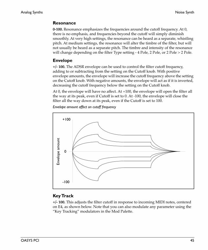
Analog Synths Noise Synth
Resonance0-100. Resonance emphasizes the frequencies around the cutoff frequency. At 0, there is no emphasis, and frequencies beyond the cutoff will simply diminish smoothly. At very high settings, the resonance can be heard as a separate, whistling pitch. At medium settings, the resonance will alter the timbre of the filter, but will not usually be heard as a separate pitch. The timbre and intensity of the resonance will change depending on the filter Type setting - 4 Pole, 2 Pole, or 2 Pole > 2 Pole.
Envelope+/- 100. The ADSR envelope can be used to control the filter cutoff frequency, adding to or subtracting from the setting on the Cutoff knob. With positive envelope amounts, the envelope will increase the cutoff frequency above the setting on the Cutoff knob. With negative amounts, the envelope will act as if it is inverted, decreasing the cutoff frequency below the setting on the Cutoff knob.
At 0, the envelope will have no affect. At +100, the envelope will open the filter all the way at its peak, even if Cutoff is set to 0. At -100, the envelope will close the filter all the way down at its peak, even if the Cutoff is set to 100.
Envelope amount affect on cutoff frequency
Key Track+/- 100. This adjusts the filter cutoff in response to incoming MIDI notes, centered on E4, as shown below. Note that you can also modulate any parameter using the “Key Tracking” modulators in the Mod Palette.
+100
-100
0
Enve
lope
am
ount
OASYS PCI 45

Noise Synth Analog Synths
Eng
lish
Key Tracking
ModeLowpass, Highpass, Bandpass. This selects whether the filter will cut high frequencies (Lowpass), cut low frequencies (Highpass), or cut all frequencies above and below the cutoff point (Bandpass).
Lowpass. Frequencies above the cutoff will be attenuated, and frequencies below the cutoff will pass through unchanged.
Highpass. Frequencies below the cutoff will be attenuated, and frequencies above the cutoff will pass through unchanged.
Bandpass. Frequencies both above and below the cutoff will be attenuated, and only frequencies right at the cutoff will pass through unchanged.
Type4 Pole, 2 Pole, 2 Pole > 2 Pole. This parameter selects the amount of frequency attenuation in the filter, and the character of the resonance.
4 Pole. This is a 24dB per octave filter. Of the three types, the 4 Pole offers the greatest attenuation of frequencies beyond the cutoff, coupled with a resonance slightly more delicate than the 2 Pole type. Many classic analog synths used this general type of filter.
2 Pole. This is a 12dB per octave filter. Compared to the 4 Pole, this offers significantly less attenuation of frequencies beyond the cutoff, but with slightly more pronounced resonance.
2 Pole > 2 Pole. This is two 12dB per octave filters in series. Of the three types, this offers by far the most extreme resonance effect. Compared with the 4 Pole, it has just a little less attenuation of frequencies beyond the cutoff.
E4MIDI Note
Valu
e0
+100
-100A0 C8
Key Track amount
-100
+100
0
+50
-50
46 OASYS PCI

Analog Synths Noise Synth
Attack0-100. This sets the attack time of the filter envelope, which controls how long it takes from the moment that the key is pressed until the envelope reaches its peak.
Decay 0-100. This sets the decay time of the filter envelope, which controls how long it takes the envelope to fall to the sustain level after the attack is complete.
Sustain0-100. This sets the sustain level for the filter envelope. After the decay time is complete, the envelope will stay at this level as long as the note is held.
Release0-100. This sets the release time of the filter envelope, which controls how long it takes the envelope to fall to zero after the note is released.
ADSR Envelope
AmplifierThese parameters control an ADSR envelope dedicated to the output volume. For a graphic explaining ADSR envelopes, see the figure “ADSR Envelope,” above.
Attack0-100. This sets the attack time of the amplitude envelope, which controls how long it takes from the moment that the key is pressed until the envelope reaches its peak.
Decay 0-100. This sets the decay time of the amplitude envelope, which controls how long it takes the envelope to fall to the sustain level after the attack is complete.
Attack time Decay time Release timeSustain while
SustainLevel
holding note
Enve
lope
Am
ount
OASYS PCI 47

Noise Synth Analog Synths
Eng
lish
Sustain0-100. This sets the sustain level for the amplitude envelope. After the decay time is complete, the envelope will stay at this level as long as the note is held.
Release0-100. This sets the release time of the amplitude envelope, which controls how long it takes the envelope to fall to zero after the note is released.
Filter Cutoff ModThis section controls the modulation of the filter by both an LFO and a dedicated modulation noise source (“Rand”).
LFO Amt0-100. This sets the initial amount of LFO modulation for the filter.
Mod SourceList of Modulation Sources. This sets the modulation source for controlling the LFO amount. For a complete list, please see “Modulation Sources” on page 2.
Mod Amount0-100. This sets the amount by which the mod source affects the LFO amount.
Rand Amt (Random Noise Modulation Amount)0-100. This sets the initial amount of filter modulation from the “Rand” noise source.
Mod SourceList of Modulation Sources. This sets the modulation source for controlling the Rand amount. For a complete list, please see “Modulation Sources” on page 2.
Mod Amount0-100. This sets the amount by which the mod source affects the Rand amount.
Output
Volume+12 to -123.9dB, -INF. This is the output volume for the Patch.
This control has extra smoothing on the DSP, to ensure zipper-free modulation. If you want to modulate the volume instantaneously via velocity, use the Vel Sens control instead.
IMPORTANT: The output volume provides up to 12dB in gain, so that you can get your signals as hot as possible. However, if filter resonance is high, settings above 0dB may cause clipping.
48 OASYS PCI

Analog Synths Noise Synth
Vel Sens (Velocity Sensitivity)0-100. This sets the sensitivity of output volume to velocity. A velocity of 127 will always result in the maximum output level, as set by the Volume control; increasing the Vel Sens will decrease the output volume for low velocities.
OASYS PCI 49

Pro Synth Analog Synths
Eng
lish
Pro SynthThe Pro Synth is a precise model of a classic analog synth, including a special 24dB per octave lowpass filter, two oscillators with multiple simultaneous waveform outputs and sync, noise generator, poly mod, specifically shaped filter and amplitude ADS envelopes, and VCA output nonlinearity.
For completely authentic playing, set the Program Edit page Voice Allocation parameter to Poly Reuse.
Poly ModThe Poly Mod section allows you to route the filter envelope or oscillator B to modulate the frequency of oscillator A, the pulse width of oscillator A, or the filter itself.
Filt Env0-100. This sets the amount of the filter envelope to be used as a Poly Mod source.
Osc B0-100. This sets the amount of oscillator B to be used as a Poly Mod source.
Freq AOn, Off. When this is turned on, the frequency of oscillator A will be modulated by the combination of the filter envelope and oscillator B, as set above. Among other things, you can use this to create frequency sweeps with the envelope, frequency modulation (as in “FM”) via oscillator B, or sync sweeps via the envelope, in conjunction with the Sync button.
PW AOn, Off. When this is turned on, the pulse width of oscillator A will be modulated by the combination of the filter envelope and oscillator B, as set above.
FilterOn, Off. When this is turned on, the filter will be modulated by the combination of the filter envelope and oscillator B, as set above. Modulating the filter with oscillator B can produce some interesting sounds.
LFO
Frequency0.00-20.00 Hz. This controls the speed of the LFO.
WaveformSaw, Triangle, Square. This sets the shape of the LFO.
50 OASYS PCI

Analog Synths Pro Synth
Oscillator A
Frequency+/- 24. This sets the coarse tuning of the oscillator over a four-octave range, in half-steps.
WaveformSawtooth, Pulse, Triangle. This selects the shape of oscillator A. If Pulse is selected, the Pulse Width control, below, sets the width of the pulse.
Pulse Width0.0-100.0. This sets the width of the pulse waveform, as a percentage of the full waveform cycle. 50.0 produces a square wave, smaller amounts produce a waveform with a shorter “up” time, and greater amounts produce a waveform with a longer “up” time, as shown below. Pulse width can also be modulated via the LFO.
Pulse Width
SyncOn, Off. This syncs Oscillator A to Oscillator B. When this is on, Oscillator B will control the pitch of Oscillator A, and changing Oscillator A’s frequency will change Osc A’s timbre, instead of its pitch.
For the classic sync sweep sound:
1. Turn Sync on.
2. Turn on Freq A in the Poly Mod section.
3. Also in the Poly Mod section, set Filt Env to about 50, and Osc B to 0.
Now, the Filter Envelope is controlling the sync sound.
4. Set the Filter Envelope parameters to create the desired sync sweep.
50% 75% 100%25%0%
OASYS PCI 51

Pro Synth Analog Synths
Eng
lish
Oscillator B
Frequency+/- 48. This sets the coarse tuning of the oscillator over an eight-octave range, in half-steps.
Fine+/- 100. This sets the fine tuning of the oscillator, in cents (1/100 of a semitone).
ShapeSawtooth, Pulse, Triangle. This selects the waveform of oscillator B. If Pulse is selected, the Pulse Width control, below, sets the width of the pulse.
Pulse Width0-100. This sets the width of the pulse waveform, as a percentage of the full waveform cycle. 50.0 produces a square wave, smaller amounts produce a waveform with a shorter “up” time, and greater amounts produce a waveform with a longer “up” time, as shown below. For a diagram, see the figure “Pulse Width,” above. Pulse width can also be modulated via the LFO.
Lo FreqOn, Off. This shifts the oscillator to a low-frequency pitch range. The Lo Freq mode is most useful when oscillator B is being used as a Poly Mod source.
KeyboardOn, Off. This enables and disables oscillator B’s pitch tracking, centered on B3. You might choose to disable tracking when using oscillator B as a Poly Mod source–and then again, you might not!
Mixer
Osc A0-100. This controls the output level of oscillator A.
Osc B0-100. This controls the output level of oscillator B.
Noise0-100. This controls the output level of the noise generator.
52 OASYS PCI

Analog Synths Pro Synth
Filter
Cutoff0-100. This controls the cutoff frequency of the special 24dB per octave lowpass filter. Frequencies above the cutoff are cut, and frequencies below the cutoff are passed through unchanged.
Generally speaking, the lower the cutoff, the darker the sound; the higher the cutoff, the brighter the sound.
Note that the Envelope, Keyboard, and Poly Mod parameters can also affect the cutoff frequency.
This control has extra smoothing on the DSP, to ensure zipper-free modulation. If instantaneous modulation is desired (such as modulation via velocity), modulate the Envelope control instead.
Resonance0-100. Resonance emphasizes the frequencies around the cutoff frequency. At 0, there is no emphasis, and frequencies above the cutoff will simply diminish smoothly. At very high settings, the resonance can be heard as a separate, whistling pitch. At medium settings, the resonance will alter the timbre of the filter, but will not usually be heard as a separate pitch.
Env (Envelope)0-100. This controls the amount of affect the envelope will have on the filter cutoff frequency, adding to the setting on the Cutoff knob. At 0, the envelope will have no affect. At +100, the envelope will open the filter all the way at its peak, even if Cutoff is set to 0.
Envelope amount affect on cutoff frequency
KeyboardOn, Off. This enables and disables filter tracking of MIDI notes, using a tracking scale identical to the original synth. Note that you can also modulate any parameter using the “Key Tracking” modulators in the Mod Palette.
+100
0
Enve
lope
am
ount
OASYS PCI 53

Pro Synth Analog Synths
Eng
lish
Attack0-100. This sets the attack time of the filter envelope, which controls how long it takes from the moment that the key is pressed until the envelope reaches its peak.
Decay 0-100. This sets the decay time of the filter envelope, which controls how long it takes the envelope to fall to the sustain level after the attack is complete.
Sustain0-100. This sets the sustain level for the filter envelope. After the decay time is complete, the envelope will stay at this level as long as the note is held.
Release0-100. This sets the release time of the filter envelope, which controls how long it takes the envelope to fall to zero after the note is released.
NOTE: The Release button (see page 56) must be enabled for the release portion of the envelope to sound. If the Release button is turned off, the envelope will fall to zero immediately upon note off.
ADSR Envelope
AmplifierThese parameters control an ADSR envelope dedicated to the output volume. For a graphic explaining ADSR envelopes, see the figure “ADSR Envelope,” above.
Attack0-100. This sets the attack time of the amplitude envelope, which controls how long it takes from the moment that the key is pressed until the envelope reaches its peak.
Attack time Decay timeRelease time (with
Sustain while
SustainLevel
holding note
Enve
lope
Am
ount
Release button on)
54 OASYS PCI

Analog Synths Pro Synth
Decay 0-100. This sets the decay time of the amplitude envelope, which controls how long it takes the envelope to fall to the sustain level after the attack is complete.
Sustain0-100. This sets the sustain level for the amplitude envelope. After the decay time is complete, the envelope will stay at this level as long as the note is held.
Release0-100. This sets the release time of the amplitude envelope, which controls how long it takes the envelope to fall to zero after the note is released.
NOTE: The Release button (see page 56) must be enabled for the release portion of the envelope to sound. If the Release button is turned off, the envelope will fall to zero immediately upon note off.
Master Tune
Master Tune+/- 100. This adjusts the master tuning of the synth, in cents (1/100 of a semitone).
Osc Edge
Key Track0-100. This adjusts the way that the brightness of the oscillator tracks the keyboard.
Controller Mod
Source Mix0-100. Both the LFO and the noise generator can be used as modulation sources. This knob determines the balance between the two. At 0, only the output of the LFO is used; at 100, only the noise generator is used.
The Mod Controller and Initial parameters control the amount of modulation.
Freq AOn, Off. This selects the frequency of oscillator A as a modulation destination.
Freq BOn, Off. This selects the frequency of oscillator B as a modulation destination.
PW AOn, Off. This selects the pulse width of oscillator A as a modulation destination.
PW BOn, Off. This selects the pulse width of oscillator B as a modulation destination.
OASYS PCI 55

Pro Synth Analog Synths
Eng
lish
FilterOn, Off. This selects the filter cutoff as a modulation destination.
Mod ControllerList of Modulation Sources. This sets the source for controlling the amount of the Source Mix sent to the selected destinations. For a complete list, please see “Modulation Sources” on page 2.
Initial0-100. This sets the amount of the Source Mix which will be applied to the selected destinations, even when the Mod Controller is at zero. Some of the sounds on the original synth called for you to set the mod wheel to the middle of its range, and then leave it there; you can use the Initial amount to replicate this.
Glide
Glide0-100. This sets the glide amount (also known as portamento) for the oscillator, which makes the pitch slide smoothly between notes. At 0, Glide is completely off. At 100, notes will take a long time to glide to the new pitch.
Note that the effects of glide will also vary depending on the Patch’s voice allocation setting, in the Program Edit window. Poly Retrig, Poly Reuse, Mono Legato, and Unison modes are generally the most suitable for use with Glide, but you may find that you like other settings as well.
ReleaseOn, Off. This enables the release segments of the envelopes. If this is turned off, the envelopes will fall to zero immediately on note off.
Volume+12 to -123.9dB, -INF. This is the output volume for the Patch.
This control has extra smoothing on the DSP, to ensure zipper-free modulation. If you want to modulate the volume instantaneously via velocity, use the Vel Sens control instead.
IMPORTANT: The output volume provides up to 12dB in gain, so that you can get your signals as hot as possible. However, if filter resonance is high, settings above 0dB may cause clipping.
Vel Sens (Velocity Sensitivity)0-100. This sets the sensitivity of output volume to velocity. A velocity of 127 will always result in the maximum output level, as set by the Volume control; increasing the Vel Sens will decrease the output volume for low velocities.
56 OASYS PCI

Analog Synths Pro Synth Mod
Pro Synth ModThis is a slightly “hot-rodded” version of the Pro Synth, with the amplifier envelope available as a poly mod source, an extra AR envelope, a ring modulator, variable key tracking on oscillator B pitch and filter cutoff, inversion for the filter envelope, and individual amounts for the controller mod destinations.
Poly ModThe Poly Mod section allows you to route the filter envelope or oscillator B to modulate the frequency of oscillator A, the pulse width of oscillator A, or the filter itself.
Filt Env0-100. This sets the amount of the filter envelope to be used as a Poly Mod source.
Osc B0-100. This sets the amount of oscillator B to be used as a Poly Mod source.
Freq AOn, Off. When this is turned on, the frequency of oscillator A will be modulated by the combination of the filter envelope and oscillator B, as set above. Among other things, you can use this to create frequency sweeps with the envelope, frequency modulation (as in “FM”) via oscillator B, or sync sweeps via the envelope, in conjunction with the Sync button.
PW AOn, Off. When this is turned on, the pulse width of oscillator A will be modulated by the combination of the filter envelope and oscillator B, as set above.
FilterOn, Off. When this is turned on, the filter will be modulated by the combination of the filter envelope and oscillator B, as set above. Modulating the filter with oscillator B can produce some interesting sounds.
LFO
Frequency0.00-20.00 Hz. This controls the speed of the LFO.
WaveformSaw, Triangle, Square. This sets the shape of the LFO.
OASYS PCI 57

Pro Synth Mod Analog Synths
Eng
lish
Oscillator A
Frequency+/- 24. This sets the coarse tuning of the oscillator over a four-octave range, in half-steps.
WaveformSawtooth, Pulse, Triangle. This selects the shape of oscillator A. If Pulse is selected, the Pulse Width control, below, sets the width of the pulse.
Pulse Width0.0-100.0. This sets the width of the pulse waveform, as a percentage of the full waveform cycle. 50.0 produces a square wave, smaller amounts produce a waveform with a shorter “up” time, and greater amounts produce a waveform with a longer “up” time, as shown below. Pulse width can also be modulated via the LFO.
Pulse Width
SyncOn, Off. This syncs Oscillator A to Oscillator B. When this is on, Oscillator B will control the pitch of Oscillator A, and changing Oscillator A’s frequency will change Osc A’s timbre, instead of its pitch.
For the classic sync sweep sound:
1. Turn Sync on.
2. Turn on Freq A in the Poly Mod section.
3. Also in the Poly Mod section, set Filt Env to about 50, and Osc B to 0.
Now, the Filter Envelope is controlling the sync sound.
4. Set the Filter Envelope parameters to create the desired sync sweep.
50% 75% 100%25%0%
58 OASYS PCI

Analog Synths Pro Synth Mod
Oscillator B
Frequency+/- 48. This sets the coarse tuning of the oscillator over an eight-octave range, in half-steps.
Fine+/- 100. This sets the fine tuning of the oscillator, in cents (1/100 of a semitone).
ShapeSawtooth, Pulse, Triangle. This selects the waveform of oscillator B. If Pulse is selected, the Pulse Width control, below, sets the width of the pulse.
Pulse Width0-100. This sets the width of the pulse waveform, as a percentage of the full waveform cycle. 50.0 produces a square wave, smaller amounts produce a waveform with a shorter “up” time, and greater amounts produce a waveform with a longer “up” time, as shown below. For a diagram, see the figure “Pulse Width,” above. Pulse width can also be modulated via the LFO.
Lo FreqOn, Off. This shifts the oscillator to a low-frequency pitch range. The Lo Freq mode is most useful when oscillator B is being used as a Poly Mod source.
Keyboard1-100. This adjusts oscillator B’s pitch tracking, centered on B3. Note that you can also modulate any parameter using the “Key Tracking” modulators in the Mod Palette.
Mixer
Osc A0-100. This controls the output level of oscillator A.
Osc B0-100. This controls the output level of oscillator B.
Noise0-100. This controls the output level of the noise generator.
OASYS PCI 59

Pro Synth Mod Analog Synths
Eng
lish
Filter
Cutoff0-100. This controls the cutoff frequency of the special 24dB per octave lowpass filter. Frequencies above the cutoff are cut, and frequencies below the cutoff are passed through unchanged.
Generally speaking, the lower the cutoff, the darker the sound; the higher the cutoff, the brighter the sound.
Note that the Envelope, Keyboard, and Poly Mod parameters can also affect the cutoff frequency.
This control has extra smoothing on the DSP, to ensure zipper-free modulation. If instantaneous modulation is desired (such as modulation via velocity), modulate the Envelope control instead.
Resonance0-100. Resonance emphasizes the frequencies around the cutoff frequency. At 0, there is no emphasis, and frequencies above the cutoff will simply diminish smoothly. At very high settings, the resonance can be heard as a separate, whistling pitch. At medium settings, the resonance will alter the timbre of the filter, but will not usually be heard as a separate pitch.
Env (Envelope)0-100. This controls the amount of affect the envelope will have on the filter cutoff frequency, adding to the setting on the Cutoff knob. At 0, the envelope will have no affect. At +100, the envelope will open the filter all the way at its peak, even if Cutoff is set to 0.
Envelope amount affect on cutoff frequency
Keyboard0-100. This adjusts the filter cutoff in response to incoming MIDI notes. Note that you can also modulate any parameter using the “Key Tracking” modulators in the Mod Palette.
+100
0
Enve
lope
am
ount
60 OASYS PCI

Analog Synths Pro Synth Mod
Attack0-100. This sets the attack time of the filter envelope, which controls how long it takes from the moment that the key is pressed until the envelope reaches its peak.
Decay 0-100. This sets the decay time of the filter envelope, which controls how long it takes the envelope to fall to the sustain level after the attack is complete.
Sustain0-100. This sets the sustain level for the filter envelope. After the decay time is complete, the envelope will stay at this level as long as the note is held.
Release0-100. This sets the release time of the filter envelope, which controls how long it takes the envelope to fall to zero after the note is released.
NOTE: The Release button (see page 56) must be enabled for the release portion of the envelope to sound. If the Release button is turned off, the envelope will fall to zero immediately upon note off.
ADSR Envelope
Amp ADSRThese parameters control an ADSR envelope dedicated to the output volume. For a graphic explaining ADSR envelopes, see the figure “ADSR Envelope,” above.
The Amp Env switch determines whether the amplifier will use this ADSR envelope, or the simple Amp AR envelope. Switching to the AR envelope allows you to use the ADSR envelope as a poly mod source, and adjust it as desired without affecting the output volume.
Attack time Decay timeRelease time (with
Sustain while
SustainLevel
holding note
Enve
lope
Am
ount
Release button on)
OASYS PCI 61

Pro Synth Mod Analog Synths
Eng
lish
Attack0-100. This sets the attack time of the amplitude envelope, which controls how long it takes from the moment that the key is pressed until the envelope reaches its peak.
Decay 0-100. This sets the decay time of the amplitude envelope, which controls how long it takes the envelope to fall to the sustain level after the attack is complete.
Sustain0-100. This sets the sustain level for the amplitude envelope. After the decay time is complete, the envelope will stay at this level as long as the note is held.
Release0-100. This sets the release time of the amplitude envelope, which controls how long it takes the envelope to fall to zero after the note is released.
NOTE: The Release button (see page 56) must be enabled for the release portion of the envelope to sound. If the Release button is turned off, the envelope will fall to zero immediately upon note off.
Ring Mod
Ring Mod0-100. This controls the output level of the ring modulator.
The ring modulator multiplies the outputs of oscillator A and oscillator B together, creating a metallic sound. The timbre will change dramatically depending on the difference in pitch between the two oscillators. Oscillator B’s fine tuning, especially when modulated, can be used to create all sorts of interesting effects. The classic ring modulation sound uses a constant pitch, so you may also want to set Oscillator B’s key tracking to 0.
Master Tune
Master Tune+/- 100. This adjusts the master tuning of the synth, in cents (1/100 of a semitone).
Osc Edge
Key Track0-100. This adjusts the way that the brightness of the oscillator tracks the keyboard.
62 OASYS PCI
Analog Synths Pro Synth Mod
Controller Mod
Source Mix0-100. Both the LFO and the noise generator can be used as modulation sources. This knob determines the balance between the two. At 0, only the output of the LFO is used; at 100, only the noise generator is used.
The Mod Controller and Initial parameters control the amount of modulation.
Freq AOn, Off. This selects the frequency of oscillator A as a modulation destination.
Freq BOn, Off. This selects the frequency of oscillator B as a modulation destination.
PW AOn, Off. This selects the pulse width of oscillator A as a modulation destination.
PW BOn, Off. This selects the pulse width of oscillator B as a modulation destination.
FilterOn, Off. This selects the filter cutoff as a modulation destination.
Mod ControllerList of Modulation Sources. This sets the source for controlling the amount of the Source Mix sent to the selected destinations. For a complete list, please see “Modulation Sources” on page 2.
Initial0-100. This sets the amount of the Source Mix which will be applied to the selected destinations, even when the Mod Controller is at zero. Some of the sounds on the original synth called for you to set the mod wheel to the middle of its range, and then leave it there; you can use the Initial amount to replicate this.
Controller Mod DepthsThis section adds modulation depth to the Pro Synth’s Controller Mod routings. Each routing can still be enabled and disabled via the switches in the Controller Mod section.
Freq A0.0-36.0. This sets the depth of oscillator A frequency modulation, in half-steps. This routing is turned on and off by the Freq A switch, in the Controller Mod section.
OASYS PCI 63

Pro Synth Mod Analog Synths
Eng
lish
Freq B0.0-36.0. This sets the depth of oscillator B frequency modulation, in half-steps. This routing is turned on and off by the Freq B switch, in the Controller Mod section.
PW A0-100 This sets the depth of oscillator A pulse width modulation. This routing is turned on and off by the PW A switch, in the Controller Mod section.
PW B0-100 This sets the depth of oscillator B pulse width modulation. This routing is turned on and off by the PW B switch, in the Controller Mod section.
Filter0-100 This sets the depth of filter cutoff modulation. This routing is turned on and off by the Filter switch, in the Controller Mod section.
Glide
Glide0-100. This sets the glide amount (also known as portamento) for the oscillator, which makes the pitch slide smoothly between notes. At 0, Glide is completely off. At 100, notes will take a long time to glide to the new pitch.
Note that the effects of glide will also vary depending on the Patch’s voice allocation setting, in the Program Edit window. Poly Retrig, Poly Reuse, Mono Legato, and Unison modes are generally the most suitable for use with Glide, but you may find that you like other settings as well.
Amp ARThe Amp Env switch determines whether the amplifier will use this simple AR envelope, or the more complex Amp ADSR envelope. Switching to the AR envelope allows you to use the ADSR envelope as a poly mod source, and adjust it as desired without affecting the output volume.
Attack0-100. This sets the attack time of the AR envelope. This is the time that it takes from the moment that the key is pressed until the envelope reaches its peak.
Release0-100. This sets the release time of the AR envelope. This is the time that it takes from the moment that the key is released until the envelope falls to zero.
64 OASYS PCI

Analog Synths Pro Synth Mod
AR Envelope
Amp EnvADSR, AR. The Amp Env switch determines whether the amplifier will use the simple Amp AR envelope, or the more complex Amp ADSR envelope. Switching to the AR envelope allows you to use the ADSR envelope as a poly mod source, and adjust it as desired without affecting the output volume.
ReleaseOn, Off. This enables the release segments of the ADSR envelopes. If this is turned off, the envelopes will fall to zero immediately on note off.
Volume+12 to -123.9dB, -INF. This is the output volume for the Patch.
This control has extra smoothing on the DSP, to ensure zipper-free modulation. If you want to modulate the volume instantaneously via velocity, use the Vel Sens control instead.
IMPORTANT: The output volume provides up to 12dB in gain, so that you can get your signals as hot as possible. However, if filter resonance is high, settings above 0dB may cause clipping.
Vel Sens (Velocity Sensitivity)0-100. This sets the sensitivity of output volume to velocity. A velocity of 127 will always result in the maximum output level, as set by the Volume control; increasing the Vel Sens will decrease the output volume for low velocities.
Attack time Release time
OASYS PCI 65

EP (Electric Piano)
Eng
lish
EP (Electric Piano)
66 OASYS PCI

EP (Electric Piano) Reed Piano
Reed PianoThis Patch models a reed-style electric piano, such as those made by a company whose name begins with “W.” It includes modeling of the hammer, the reed, and the pickup.
Hammer
Width0-100. This controls the width of the hammer. The default value is 50; values above or below this will cause the timbre to become darker.
Width ModList of Modulation Sources. This sets the modulation source for controlling the Hammer Width. For a complete list, please see “Modulation Sources” on page 2.
Amount0-100. This sets the amount by which the mod source affects the Hammer Width.
Force0-100. This controls the force with which the hammer strikes the reed. Higher forces result in a brighter, more aggressive timbre. Often, it’s best to set the Force knob to a fairly low value, and then use velocity as a modulator under Force Mod.
Force ModList of Modulation Sources. This sets the modulation source for controlling the Hammer Force. For a complete list, please see “Modulation Sources” on page 2.
Amount0-100. This sets the amount by which the mod source affects the Hammer Force.
Reed
Decay0-100. This sets the decay time for the reed.
Decay ModList of Modulation Sources. This sets the modulation source for controlling the Reed Decay. For a complete list, please see “Modulation Sources” on page 2.
Amount0-100. This sets the amount by which the mod source affects the decay.
OASYS PCI 67

Reed Piano EP (Electric Piano)
Eng
lish
Release0-100. This sets the release time for the reed.
Release ModList of Modulation Sources. This sets the modulation source for controlling the Reed Release. For a complete list, please see “Modulation Sources” on page 2.
Amount0-100. This sets the amount by which the mod source affects the Reed Release.
Pickup
Low Cut0-100. This controls the amount of low frequency attenuation.
Pickup SelectPickup 1, Pickup 2. The pickup type has a large affect on the sound.
Pickup 1. This offers a classic reed piano timbre.
Pickup 2. This offers a more aggressive timbre.
Volume0-100. This sets the overall volume output of the piano.
Position0-100. This controls the position of the pickup on the reed. At lower values, the first harmonic will become louder than the fundamental, so that the pitch appears to shift up by an octave.
Position ModList of Modulation Sources. This sets the modulation source for controlling the Pickup Position. For a complete list, please see “Modulation Sources” on page 2.
Amount0-100. This sets the amount by which the mod source affects the Pickup Position.
68 OASYS PCI

Guitar
Guitar
OASYS PCI 69

Plucked String Guitar
Eng
lish
Plucked StringThis Patch models plucked string instruments, such as guitars. It includes string gauge, bridge rigidity, control over pick type and technique, pickup position and tone, and more.
Damping
Damping0-100. This controls the decay time for the string’s high frequencies. Lower settings mean a shorter high frequency decay time. Damping interacts with the Decay parameter, below, which controls the overall decay time.
CenterC-1 to G#9. This sets the center note for the damping key tracking, as set by the Key Track parameter, below.
Key Track+/-100. This adjusts damping as you play higher and lower on the keyboard. At the center key (as set above), the damping will be exactly the value set by the Damping knob. With positive tracking, the damping will increase as you play above the center key, and decrease as you play below it. With negative tracking, damping will decrease as you play above the center key, and increase as you play below it.
Damping ModList of Modulation Sources. This sets the modulation source for controlling the damping. For a complete list, please see “Modulation Sources” on page 2.
Amount0-100. This sets the amount by which the mod source affects the damping.
Maximum0-100. This sets the maximum amount of damping, even with modulation.
Decay
Decay0-100. This controls the overall decay time of the string.
CenterC-1 to G#9. This sets the center note for the damping key tracking, as set by the Key Track parameter, below.
70 OASYS PCI

Guitar Plucked String
Key Track+/-100. This adjusts the decay time as you play higher and lower on the keyboard. At the center key (as set above), the decay time will be exactly the value set by the Decay knob. With positive tracking, the decay time will increase as you play above the center key, and decrease as you play below it. With negative tracking, the decay time will decrease as you play above the center key, and increase as you play below it.
Release0-100. This sets the overall release time for the string–the time that it takes to fade away after note-off.
Dispersion
Dispersion0-100. This models the gauge of the string. Higher dispersion settings mean thicker-gauge strings. Higher values increase the inharmonicity of the string; at extreme values, it will create bell-like timbres, as if you were hitting a bar of metal.
CenterC-1 to G#9. This sets the center note for the dispersion key tracking, as set by the Key Track parameter, below.
Key Track+/-100. This adjusts the dispersion as you play higher and lower on the keyboard (as if the string gauge was getting lighter, as it does on most stringed instruments). At the center key (as set above), the dispersion will be exactly the value set by the Dispersion knob. With positive tracking, the dispersion will increase as you play above the center key, and decrease as you play below it. With negative tracking, the dispersion will decrease as you play above the center key, and increase as you play below it.
Nonlinearity
Amount0.0-100.0. This models the instability of the string’s bridge. Greater nonlinearity means a less rigid bridge. At higher levels, this causes the characteristic buzzing sound of some non-western stringed instruments, instruments such as the sitar.
Pitch Mod
Pitch Bend ModeNormal, Step. This determines how the string responds to pitch modulation.
Normal. The pitch will change smoothly when modulated, as if bending the string.
OASYS PCI 71

Plucked String Guitar
Eng
lish
Step. The pitch will change by half-step increments, as if hitting the frets on a guitar.
Pitch ModList of Modulation Sources. This sets the modulation source for controlling the pitch. For a complete list, please see “Modulation Sources” on page 2.
Amount0.0-24.0. This sets the amount by which the mod source affects the pitch, in half-steps.
Pluck
TypeFolk, Jazz, Smooth, Noisy, This models different types of plucking actions, including picks and finger-plucking. The pluck type sets the basic tone of the plucked string.
The Noise controls, below, offer a different way to “pluck” the string. You can also use Pluck and Noise together, to create specific tones.
Width0.0-100.0. This models the time that the pick is in contact with the string, which is a combination of the size and thickness of the pick, and the speed at which the pick is moving.
The width adjusts the tone of the initial string excitation; low settings emphasize lower frequencies, and high settings emphasize high frequencies.
Level0.0-100.0. This adjusts the force of the pluck. If the level is 0, the Pluck will not affect the string at all.
Vel Mod (Velocity Modulation)0.0-100.0. This allows you to modulate the pluck level via velocity. A velocity of 127 will add the specified amount to the setting on the Level knob.
Position0.0-100.0. This models the position of the plucking action along the string.
Tone+/-100. This controls the affect of the Position parameter on the overall tone. When Tone is set to 0, position has no affect. Settings around -100 are often the most realistic.
72 OASYS PCI

Guitar Plucked String
NoiseThese controls allow you to “pluck” the string using filtered noise.
The Pluck controls, above, offer a different way to “pluck” the string. You can also use Pluck and Noise together, to create specific tones.
Level0.0-100.0. This adjusts the level of the noise.
Vel Mod (Velocity Modulation)0.0-100.0. This allows you to modulate the noise level via velocity. A velocity of 127 will add the specified amount to the setting on the Level knob.
Cutoff+/-100. This adjusts the tone of the noise.
Brightness
Cutoff+/-100. This adjusts the overall brightness of the string.
Vel Mod (Velocity Modulation)0.0-100.0. This allows you to modulate the cutoff via velocity. A velocity of 127 will add the specified amount to the setting on the Cutoff knob.
Vibrato
Frequency0.0-20.0 Hz. This controls the initial speed of the vibrato.
Frequency ModList of Modulation Sources. This sets the modulation source for controlling the vibrato frequency. For a complete list, please see “Modulation Sources” on page 2.
Amount0.0-10.0Hz. This sets the amount, in Hz, by which the mod source affects the vibrato frequency. When the mod source is at its maximum value, it will add this amount to the setting on the Frequency knob.
Depth0-100. This controls the initial depth of the vibrato–the amount of pitch modulation.
Depth ModList of Modulation Sources. This sets the modulation source for controlling the vibrato depth. For a complete list, please see “Modulation Sources” on page 2.
OASYS PCI 73

Plucked String Guitar
Eng
lish
Amount0-100. This sets the amount by which the mod source affects the vibrato depth.
Pickup
PickupOn, Off. This enables the pickup modeling. Turning this off is the same as setting the Tone to 0.
Position0.0-100.0. This adjusts the position of the pickup along the string.
Tone+/-100. This controls the affect of the Position parameter on the overall tone. When Tone is set to 0, position has no affect.
74 OASYS PCI

Guitar Small Plucked String
Small Plucked StringThis Patch is a more DSP-efficient plucked string model. It offers higher polyphony than the Plucked String Patch, but fewer features.
Damping
Damping0-100. This controls the decay time for the string’s high frequencies. Lower settings mean a shorter high frequency decay time. Damping interacts with the Decay parameter, below, which controls the overall decay time.
CenterC-1 to G#9. This sets the center note for the damping key tracking, as set by the Key Track parameter, below.
Key Track+/-100. This adjusts damping as you play higher and lower on the keyboard. At the center key (as set above), the damping will be exactly the value set by the Damping knob. With positive tracking, the damping will increase as you play above the center key, and decrease as you play below it. With negative tracking, damping will decrease as you play above the center key, and increase as you play below it.
Damping ModList of Modulation Sources. This sets the modulation source for controlling the damping. For a complete list, please see “Modulation Sources” on page 2.
Amount0-100. This sets the amount by which the mod source affects the damping.
Maximum0-100. This sets the maximum amount of damping, even with modulation.
Decay
Decay0-100. This controls the overall decay time of the string.
CenterC-1 to G#9. This sets the center note for the damping key tracking, as set by the Key Track parameter, below.
OASYS PCI 75

Small Plucked String Guitar
Eng
lish
Key Track+/-100. This adjusts the decay time as you play higher and lower on the keyboard. At the center key (as set above), the decay time will be exactly the value set by the Decay knob. With positive tracking, the decay time will increase as you play above the center key, and decrease as you play below it. With negative tracking, the decay time will decrease as you play above the center key, and increase as you play below it.
Release0-100. This sets the overall release time for the string–the time that it takes to fade away after note-off.
Pitch Mod
Pitch Bend ModeNormal, Step. This determines how the string responds to pitch modulation.
Normal. The pitch will change smoothly when modulated, as if bending the string.
Step. The pitch will change by half-step increments, as if hitting the frets on a guitar.
Pitch ModList of Modulation Sources. This sets the modulation source for controlling the pitch. For a complete list, please see “Modulation Sources” on page 2.
Amount0.0-24.0. This sets the amount by which the mod source affects the pitch, in half-steps.
Pluck
TypeFolk, Smooth, Noisy, This models different types of plucking actions, including picks and finger-plucking. The pluck type sets the basic tone of the plucked string.
The Noise controls, below, offer a different way to “pluck” the string. You can also use Pluck and Noise together, to create specific tones.
Width0.0-100.0. This models the time that the pick is in contact with the string, which is a combination of the size and thickness of the pick, and the speed at which the pick is moving.
The width adjusts the tone of the initial string excitation; low settings emphasize lower frequencies, and high settings emphasize high frequencies.
76 OASYS PCI

Guitar Small Plucked String
Level0.0-100.0. This adjusts the force of the pluck. If the level is 0, the Pluck will not affect the string at all.
Vel Mod (Velocity Modulation)0.0-100.0. This allows you to modulate the pluck level via velocity. A velocity of 127 will add the specified amount to the setting on the Level knob.
NoiseThese controls allow you to “pluck” the string using filtered noise.
The Pluck controls, above, offer a different way to “pluck” the string. You can also use Pluck and Noise together, to create specific tones.
Level0.0-100.0. This adjusts the level of the noise.
Vel Mod (Velocity Modulation)0.0-100.0. This allows you to modulate the noise level via velocity. A velocity of 127 will add the specified amount to the setting on the Level knob.
Cutoff+/-100. This adjusts the tone of the noise.
Brightness
Cutoff+/-100. This adjusts the overall brightness of the string.
Vel Mod (Velocity Modulation)0.0-100.0. This allows you to modulate the cutoff via velocity. A velocity of 127 will add the specified amount to the setting on the Cutoff knob.
Vibrato
Frequency0.0-20.0 Hz. This controls the initial speed of the vibrato.
Frequency ModList of Modulation Sources. This sets the modulation source for controlling the vibrato frequency. For a complete list, please see “Modulation Sources” on page 2.
OASYS PCI 77

Small Plucked String Guitar
Eng
lish
Amount0.0-10.0Hz. This sets the amount, in Hz, by which the mod source affects the vibrato frequency. When the mod source is at its maximum value, it will add this amount to the setting on the Frequency knob.
Depth0-100. This controls the initial depth of the vibrato–the amount of pitch modulation.
Depth ModList of Modulation Sources. This sets the modulation source for controlling the vibrato depth. For a complete list, please see “Modulation Sources” on page 2.
Amount0-100. This sets the amount by which the mod source affects the vibrato depth.
78 OASYS PCI

Guitar Slap Bass
Slap BassThis Patch models a slapped electric bass. It includes string gauge, bridge rigidity, control over pick type and technique, pickup position and tone, and more.
String Damping
Damping0-100. This controls the decay time for the string’s high frequencies. Lower settings mean a shorter high frequency decay time. Damping interacts with the Decay parameter, below, which controls the overall decay time.
CenterC-1 to G#9. This sets the center note for the damping key tracking, as set by the Key Track parameter, below.
Key Track+/-100. This adjusts damping as you play higher and lower on the keyboard. At the center key (as set above), the damping will be exactly the value set by the Damping knob. With positive tracking, the damping will increase as you play above the center key, and decrease as you play below it. With negative tracking, damping will decrease as you play above the center key, and increase as you play below it.
Damping ModList of Modulation Sources. This sets the modulation source for controlling the damping. For a complete list, please see “Modulation Sources” on page 2.
Amount0-100. This sets the amount by which the mod source affects the damping.
Maximum0-100. This sets the maximum amount of damping, even with modulation.
String Decay
Decay0-100. This controls the overall decay time of the string.
CenterC-1 to G#9. This sets the center note for the damping key tracking, as set by the Key Track parameter, below.
OASYS PCI 79

Slap Bass Guitar
Eng
lish
Key Track+/-100. This adjusts the decay time as you play higher and lower on the keyboard. At the center key (as set above), the decay time will be exactly the value set by the Decay knob. With positive tracking, the decay time will increase as you play above the center key, and decrease as you play below it. With negative tracking, the decay time will decrease as you play above the center key, and increase as you play below it.
Release0-100. This sets the overall release time for the string–the time that it takes to fade away after note-off.
String Dispersion
Dispersion0-100. This models the gauge of the string. Higher dispersion settings mean thicker-gauge strings. Higher values increase the inharmonicity of the string; at extreme values, it will create bell-like timbres, as if you were hitting a bar of metal.
CenterC-1 to G#9. This sets the center note for the dispersion key tracking, as set by the Key Track parameter, below.
Key Track+/-100. This adjusts the dispersion as you play higher and lower on the keyboard (as if the string gauge was getting lighter, as it does on most stringed instruments). At the center key (as set above), the dispersion will be exactly the value set by the Dispersion knob. With positive tracking, the dispersion will increase as you play above the center key, and decrease as you play below it. With negative tracking, the dispersion will decrease as you play above the center key, and increase as you play below it.
Pickup
Position0-100. This adjusts the position of the pickup along the string.
Force
Initial0-100. This adjusts the force of the slap.
Vel. Mod. (Velocity Modulation)0-100. This allows you to modulate the force via velocity. A velocity of 127 will add the specified amount to the setting on the Force knob.
80 OASYS PCI

Guitar Slap Bass
Maximum0-100. This sets the maximum amount of force, even with modulation.
Velocity
Velocity0-100. This models the velocity of the “slap” across the string, which affects the amount of high frequencies in the sound.
Contact Time0-100. This models the amount of time that the pick is in contact with the string. Low settings emphasize lower frequencies, and high settings emphasize high frequencies.
Vel. Mod. (Velocity Modulation)+/-100. This allows you to modulate the contact time via velocity. A velocity of 127 will add or subtract the specified amount to the setting on the Contact Time knob.
Slap NoiseThese controls allow you to adjust the level and timbre of the sharp “slap” sound.
Noise0-100. This adjusts the level of the slap noise.
Cutoff0-100. This adjusts the cutoff frequency of a filter dedicated to the slap noise.
Vel. Mod. (Velocity Modulation)0-100. This allows you to modulate the cutoff frequency of the noise via velocity. A velocity of 127 will add the specified amount to the setting on the Level knob.
Resonance0-100. This adjusts the resonance of a filter dedicated to the slap noise.
Vibrato
Frequency0.0-20.0 Hz. This controls the initial speed of the vibrato.
Frequency ModList of Modulation Sources. This sets the modulation source for controlling the vibrato frequency. For a complete list, please see “Modulation Sources” on page 2.
OASYS PCI 81

Slap Bass Guitar
Eng
lish
Amount0.0-10.0Hz. This sets the amount, in Hz, by which the mod source affects the vibrato frequency. When the mod source is at its maximum value, it will add this amount to the setting on the Frequency knob.
Depth0-100. This controls the initial depth of the vibrato–the amount of pitch modulation.
Depth ModList of Modulation Sources. This sets the modulation source for controlling the vibrato depth. For a complete list, please see “Modulation Sources” on page 2.
Amount0-100. This sets the amount by which the mod source affects the vibrato depth.
82 OASYS PCI

Guitar Small Slap Bass
Small Slap BassThis Patch is a more DSP-efficient slap bass model. It offers higher polyphony than the Slap Bass Patch, but fewer features.
String
Decay0-100. This controls the overall decay time of the string.
Damping0-100. This controls the decay time for the string’s high frequencies. Lower settings mean a shorter high frequency decay time. Damping interacts with the Decay parameter, below, which controls the overall decay time.
Pickup Position0-100. This adjusts the position of the pickup along the string.
Force
Initial0.0-100.0. This adjusts the force of the slap.
Vel. Mod. (Velocity Modulation)0-100. This allows you to modulate the force via velocity. A velocity of 127 will add the specified amount to the setting on the Force knob.
Maximum0-100. This sets the maximum amount of force, even with modulation.
Velocity
Velocity0-100. This models the velocity of the “slap” across the string, which affects the amount of high frequencies in the sound.
Contact Time0-100. This models the amount of time that the pick is in contact with the string. Low settings emphasize lower frequencies, and high settings emphasize high frequencies.
Vel. Mod. (Velocity Modulation)+/-100. This allows you to modulate the contact time via velocity. A velocity of 127 will add or subtract the specified amount to the setting on the Contact Time knob.
OASYS PCI 83
Small Slap Bass Guitar
Eng
lish
Slap NoiseThese controls allow you to adjust the level and timbre of the sharp “slap” sound.
Noise0-100. This adjusts the level of the slap noise.
Cutoff0-100. This adjusts the cutoff frequency of a filter dedicated to the slap noise.
Vel. Mod. (Velocity Modulation)0-100. This allows you to modulate the cutoff frequency of the noise via velocity. A velocity of 127 will add the specified amount to the setting on the Level knob.
Resonance0-100. This adjusts the resonance of a filter dedicated to the slap noise.
Vibrato
Frequency0.0-20.0 Hz. This controls the initial speed of the vibrato.
Frequency ModList of Modulation Sources. This sets the modulation source for controlling the vibrato frequency. For a complete list, please see “Modulation Sources” on page 2.
Amount0.0-10.0Hz. This sets the amount, in Hz, by which the mod source affects the vibrato frequency. When the mod source is at its maximum value, it will add this amount to the setting on the Frequency knob.
Depth0-100. This controls the initial depth of the vibrato–the amount of pitch modulation.
Depth ModList of Modulation Sources. This sets the modulation source for controlling the vibrato depth. For a complete list, please see “Modulation Sources” on page 2.
Amount0-100. This sets the amount by which the mod source affects the vibrato depth.
84 OASYS PCI

Organ
Organ
OASYS PCI 85

Tonewheel Organ Organ
Eng
lish
Tonewheel OrganThis Patch models a classic tonewheel organ, including complete drawbar control, perfect tonewheel phase coherency, fully programmable key click, and true mono percussion.
Drawbars
16'0.0-8.0. This controls the volume of the 16’ drawbar.
5 1/3'0.0-8.0. This controls the volume of the 5 1/3’ drawbar.
8'0.0-8.0. This controls the volume of the 8’ drawbar.
4'0.0-8.0. This controls the volume of the 4’ drawbar.
2 2/3'0.0-8.0. This controls the volume of the 2 2/3’ drawbar.
2'0.0-8.0. This controls the volume of the 2’ drawbar.
1 3/5'0.0-8.0. This controls the volume of the 1 3/5’ drawbar.
1 1/3'0.0-8.0. This controls the volume of the1 1/3’ drawbar.
1'0.0-8.0. This controls the volume of the 1’ drawbar.
Key Click
Key ClickOn, Off. This enables and disables the key click.
Level0-100. This controls the volume of the key click.
86 OASYS PCI

Organ Tonewheel Organ
TriggerDown, Up and Down. This controls whether the key click will be triggered only when a key is pressed down, or when a key is either pressed down or released.
Down. The key click will only trigger when a key is pressed down.
Up and Down. The key click will trigger both when a key is pressed down, and when it is released.
Attack0-100. This controls the attack time of the key click.
Decay0-100. This controls the decay time of the key click.
Cutoff0-100. This controls the timbre of the key click, by setting the cutoff frequency of a lowpass filter.
Clip0-100. The key click is actually created by sparks arcing across the bus bar as the tonewheel is switched on. This models the randomness of that spark. The sound ranges from something like white noise to a noise which is speckly and intermittent.
Contact0-100. This controls how quickly each tonewheel turns on and off. Low settings mean fast on/off, and high settings mean slower on/off.Very fast on/off times will result in a slight click, as the tonewheel jumps instantly to full volume.
PercussionThe Percussion section controls the short “blip” at the beginning of the note. Like the original instrument, percussion is mono; if you play one note, hold it down, and then play a second note, the percussion will sound only for the first note.
PercussionOn, Off. This enables and disables the percussion.
Level0-100. This controls the volume of the percussion.
Harmonic4’, 2 2/3’. This controls the pitch of the percussion.
4’. The percussion’s pitch will be 2 octaves above the fundamental.
2 2/3’. The percussion’s pitch will be 3 octaves and a fifth above the fundamental.
OASYS PCI 87

Tonewheel Organ Organ
Eng
lish
Attack0-100. This controls the attack time of the percussion. See also the Width parameter, below, which controls the overall duration of the percussion.
Decay0-100. This controls the decay time of the percussion.
Width0-100. This controls the total duration of the percussion. If the width is set to a small value, and the attack is set to a large value, you may not hear the percussion at all.
Volume0-100. This controls the output volume of the entire organ. You might wish to modulate this with a foot pedal.
88 OASYS PCI

Organ Z1 Organ
Z1 OrganThis Patch is the additive synthesis organ model from the Korg Z1. There are three main drawbars, each with assignable waveform and tuning ratio, a sub-oscillator, and a simple envelope.
Drawbar 1
WaveformTriangle, Sine, Sine + 1st Harmonic, Sine + 1st & 2nd Harm. This sets the waveform for the first drawbar.
Tuning Ratio1 (16’), 2 (8’), 3 (5 1/3’), 4 (4’), 5, 6 (2 2/3’), 7, 8 (2’), 9, 10 (1 3/5’), 11, 12 (1 1/3’), 13, 14, 15, 16 (1’). This sets the coarse tuning for the first drawbar. The number indicates the tuning ratio from the root pitch. In additive synthesis, this is sometimes referred to as the “partial.”
Traditional organ “foot” tunings are noted where applicable.
Fine Tune+/-100. This sets the fine tuning for the first drawbar, in cents (1/100 of a semitone).
Level0-100. This sets the volume level for the first drawbar.
Mod SourceList of Modulation Sources. This sets the modulation source for controlling the level. For a complete list, please see “Modulation Sources” on page 2.
Amount+/-100. This sets the amount by which the mod source affects the level.
Drawbar 2
WaveformTriangle, Sine, Sine + 1st Harmonic, Sine + 1st & 2nd Harm. This sets the waveform for the second drawbar.
Tuning Ratio1 (16’), 2 (8’), 3 (5 1/3’), 4 (4’), 5, 6 (2 2/3’), 7, 8 (2’), 9, 10 (1 3/5’), 11, 12 (1 1/3’), 13, 14, 15, 16 (1’). This sets the coarse tuning for the second drawbar. The number indicates the tuning ratio from the root pitch. In additive synthesis, this is sometimes referred to as the “partial.”
OASYS PCI 89

Z1 Organ Organ
Eng
lish
Traditional organ “foot” tunings are noted where applicable.
Fine Tune+/-100. This sets the fine tuning for the second drawbar, in cents (1/100 of a semitone).
Level0-100. This sets the volume level for the second drawbar.
Mod SourceList of Modulation Sources. This sets the modulation source for controlling the level. For a complete list, please see “Modulation Sources” on page 2.
Amount+/-100. This sets the amount by which the mod source affects the level.
Drawbar 3
WaveformTriangle, Sine, Sine + 1st Harmonic, Sine + 1st & 2nd Harm. This sets the waveform for the third drawbar.
Tuning Ratio1 (16’), 2 (8’), 3 (5 1/3’), 4 (4’), 5, 6 (2 2/3’), 7, 8 (2’), 9, 10 (1 3/5’), 11, 12 (1 1/3’), 13, 14, 15, 16 (1’). This sets the coarse tuning for the third drawbar. The number indicates the tuning ratio from the root pitch. In additive synthesis, this is sometimes referred to as the “partial.”
Traditional organ “foot” tunings are noted where applicable.
Fine Tune+/-100. This sets the fine tuning for the third drawbar, in cents (1/100 of a semitone).
Level0-100. This sets the volume level for the third drawbar.
Mod SourceList of Modulation Sources. This sets the modulation source for controlling the level. For a complete list, please see “Modulation Sources” on page 2.
Amount+/-100. This sets the amount by which the mod source affects the level.
90 OASYS PCI

Organ Z1 Organ
Sub-OscillatorThe sub-oscillator creates a sine waveform, and has a lower range than the three drawbars.
Tuning Ratio0.5 (32’), 1 (16’), 2 (8’), 4 (4’). This sets the coarse tuning for the third drawbar. The number indicates the tuning ratio from the root pitch. In additive synthesis, this is sometimes referred to as the “partial.”
Traditional organ “foot” tunings are also noted.
Fine Tune+/-100. This sets the fine tuning for the third drawbar, in cents (1/100 of a semitone).
Level0-100. This sets the volume level for the third drawbar.
Mod SourceList of Modulation Sources. This sets the modulation source for controlling the level. For a complete list, please see “Modulation Sources” on page 2.
Amount+/-100. This sets the amount by which the mod source affects the level.
Amp EnvelopeThis attack-release envelope controls the amplitude, or volume, of the Patch.
Attack0-100. This sets the attack time of the amplitude envelope–the time that it takes from the moment that the key is pressed until the envelope reaches its peak.
Release0-100. This sets the release time of the amplitude envelope–the time that it takes from the moment that the key is released until the envelope falls to zero.
OASYS PCI 91

Z1 Organ Organ
Eng
lish
AR Envelope
Pitch Modulation
Mod SourceList of Modulation Sources. This sets the modulation source for controlling the pitch. For a complete list, please see “Modulation Sources” on page 2.
Amount+/-24. This sets the amount by which the mod source affects the pitch, in semitones.
Attack time Release time
92 OASYS PCI
Organ Z1 Organ
OASYS PCI 93

PCM
Eng
lish
PCM
94 OASYS PCI

PCM PCM Patches Overview
PCM Patches OverviewOASYS PCI includes a number of PCM-based Patches, each with different features intended for various different purposes. The chart below shows how the Patches relate to one another.
Patch Application Oscillators Vel Switch Filter Envelopes LFOs Special
Argon 4+ All 2 2-level4-pole
resonant2 ADSR 2 2 pitch ramps
Cobalt 2 All 1 2-level 2-pole 2 ADSR - -
Cobalt 2 St All 1 stereo 2-level 2-pole 2 ADSR - -
Cobalt 4 All 1 2-level 4-pole 2 ADSR - -
Cobalt 4+ All 1 2-level4-pole
resonant2 ADSR - -
Krypton 2 Drums 1 2-level 2-pole 1 AD - -
Krypton 2e Drums 1 2-level 2-pole 2 AD - pan
Krypton 2p Drums 1 2-level 2-pole 1 AD - pan
Looper Loops 1 - - 1 AR
Looper St Loops 1 stereo - - 1 AR
Looper X Loops 1 - - 1 AR pan
Xenon 2 All 1 2-level 2-pole 2 ADSR - pitch ramp
Xenon 2i All 1 2-level 2-pole 2 ADSR 1
Extra-high-quality inter-
polation; pitch ramp
Xenon 4 All 1 2-level 4-pole 2 ADSR 1 pitch ramp
Xenon 4+ All 1 2-level4-pole
resonant2 ADSR 2 pitch ramp
Xenon 4m All 1 2-level4-pole
resonantmultimode
2 ADSR 2 pitch ramp
OASYS PCI 95

Argon 4+ PCM
Eng
lish
Argon 4+Argon 4+ is a dual-oscillator PCM synth plug-in with two-level velocity-switched multisamples. Features include a 4 pole (24dB per octave) resonant lowpass filter, two DSP-rate ADSR envelopes for filter and amplitude modulation, two pitch ramps, and two DSP-rate, complex MIDI-synchronized global LFOs.
Oscillator 1
Samples
Lo MultisampleThis is the low-velocity Multisample. When a note’s MIDI velocity is lower than the Vel Switch setting. you’ll hear this Multisample.
To select a Multisample:
1. Drag a Multisample from the Catalog onto the desired Multisample slot.
(MacOS Only: Alternatively, you can select the Multisample slot and then double-click the name of the Multisample in the Catalog.)
Double-clicking on the Multisample name brings up the Multisample Edit window.
You can delete a Multisample from a Patch by using the Delete key, or the Edit menu’s cut command.
Hi MultisampleThis is the high-velocity Multisample. When a note’s MIDI velocity is equal to or higher than the Vel Switch setting. you’ll hear this Multisample.
Lo Level0-100. This controls the volume level of the low (Lo) Multisample.
Hi Level0-100. This controls the volume level of the high (Hi) Multisample.
Vel Switch0-127. You can use velocity to switch between the two Multisamples. Velocities lower than the Vel Switch setting will play the Lo Multisample, and velocities equal to or higher than the Vel Switch setting will play the Hi Multisample.
Pitch
Tune+/- 48. This sets the coarse tuning of the oscillator over an eight-octave range, in half-steps.
96 OASYS PCI

PCM Argon 4+
Fine+/- 100. This sets the fine tuning of the oscillator, in cents (1/100 of a semitone).
Slope+/- 2.00. The Pitch Slope allows you to adjust the way in which the oscillator’s pitch changes as you play higher or lower on your MIDI controller. The slope is centered around middle C (C4).
+1.00 is the default setting; pitch will track the keyboard normally.
Values above +1.00 increasingly stretch the oscillator tuning. In other words, above C4 the oscillator gets increasingly sharp, and below C4 the oscillator gets increasingly flat.
+2.00 means the pitch changes two octaves over only a single octave of MIDI input.
+0.50 means that an octave of pitch is spread out over two octaves of MIDI input, producing a quarter-tone scale.
0.00 makes all notes play at middle C (C4).
A negative Slope value inverts the pitch tracking, so that as you play higher on your controller the pitch gets lower, and vice versa. Normally you would use this adjustment on oscillators that contribute harmonics within a patch, rather than on ones responsible for fundamental pitch.
NOTE: Pitch slope also changes the way that Multisamples are mapped across the keyboard. When you are editing a Multisample in the Multisample Edit window, it’s generally best to make sure that Pitch Slope is set to 1.00.
Pitch RampThe Pitch Ramp lets you create an automatic pitch-bend at the start of the sound. The pitch-bend can start from either below or above the normal pitch of the note.
Depth +/- 12. This sets the difference between the ramp’s initial pitch and the normal pitch of the key, in half-steps. Set this to 0 to turn off the Pitch Ramp.
Time0-100. This sets the duration of the ramp - the time that it takes the pitch to reach the normal pitch of the key. 0 is the fastest time; 100 is the slowest.
OASYS PCI 97

Argon 4+ PCM
Eng
lish
Pitch Ramp affect on pitch
Pitch Mod
LFO 10.0-100.0. This sets the amount by which LFO 1 modulates pitch.
LFO 20.0-100.0. This sets the amount by which LFO 2 modulates pitch.
Oscillator 2The parameters for Oscillator 2 are the same as those for Oscillator 1, as described above.
Oscillator 1-2 Mix
Osc Mix0-100. This sets the volume balance between Oscillator 1 and Oscillator 2. At 50, the balance between the two is equal; 0 sets the mix to only Oscillator 1, and 100 sets the mix to only Oscillator 2.
LFO 10.0-100.0. This sets the amount by which LFO 1 modulates the Oscillator Mix.
LFO 20.0-100.0. This sets the amount by which LFO 2 modulates Oscillator Mix.
+12.0
-12.0
0
Dep
th
Normal Pitch
Time
98 OASYS PCI

PCM Argon 4+
4 Pole Filter
Filter
Cutoff0-100. This controls the cutoff frequency of the 24dB per octave lowpass filter. Frequencies above the cutoff are cut, and frequencies below the cutoff are passed through unchanged.
Generally speaking, the lower the cutoff, the darker the sound; the higher the cutoff, the brighter the sound.
Note that the Envelope and Key Track parameters also affect the cutoff frequency.
This control has extra smoothing on the DSP, to ensure zipper-free modulation. If instantaneous modulation is desired (such as modulation via velocity), modulate the Filter Mod section’s Envelope control instead.
Resonance0-100. Resonance emphasizes the frequencies around the cutoff frequency. At 0, there is no emphasis, and frequencies above the cutoff will simply diminish smoothly. At very high settings, the resonance can be heard as a separate, whistling pitch. At medium settings, the resonance will alter the timbre of the filter, but will not usually be heard as a separate pitch.
Filter Mod
Envelope+/- 100. The ADSR envelope can be used to control the filter cutoff frequency, adding to or subtracting from the setting on the Cutoff knob. With positive envelope amounts, the envelope will increase the cutoff frequency above the setting on the Cutoff knob. With negative amounts, the envelope will act as if it is inverted, decreasing the cutoff frequency below the setting on the Cutoff knob.
At 0, the envelope will have no affect. At +100, the envelope will open the filter all the way at its peak, even if Cutoff is set to 0. At -100, the envelope will close the filter all the way down at its peak, even if the Cutoff is set to 100.
OASYS PCI 99

Argon 4+ PCM
Eng
lish
Envelope amount affect on cutoff frequency
LFO 1+/- 100.0. LFO 1 can be used to control the filter cutoff frequency, adding to or subtracting from the setting on the Cutoff knob.
LFO 2+/- 100.0. LFO 2 can be used to control the filter cutoff frequency, adding to or subtracting from the setting on the Cutoff knob.
Envelope
Attack0-100. This sets the attack time of the filter envelope, which controls how long it takes from the moment that the key is pressed until the envelope reaches its peak.
Decay 0-100. This sets the decay time of the filter envelope, which controls how long it takes the envelope to fall to the sustain level after the attack is complete.
Sustain0-100. This sets the sustain level for the filter envelope. After the decay time is complete, the envelope will stay at this level as long as the note is held.
Release0-100. This sets the release time of the filter envelope, which controls how long it takes the envelope to fall to zero after the note is released.
+100
-100
0
Enve
lope
am
ount
100 OASYS PCI

PCM Argon 4+
ADSR Envelope
Key Tracking
Amount+/- 100. This adjusts the filter cutoff as you play higher and lower on the keyboard. At the center key (as set below), the cutoff will be exactly the value set by the Cutoff knob. With positive tracking, the cutoff will increase as you play above the center key, and decrease as you play below it. With negative tracking, cutoff will decrease as you play above the center key, and increase as you play below it.
Note that you can also modulate any parameter using the “Key Tracking” modulators in the Mod Palette.
CenterC-1 to G#9. This sets the key around which the filter tracking is centered.
Amplifier
EnvelopeThese parameters control an ADSR envelope dedicated to the output volume. For a graphic explaining ADSR envelopes, see the figure “ADSR Envelope,” above.
Attack0-100. This sets the attack time of the amplitude envelope, which controls how long it takes from the moment that the key is pressed until the envelope reaches its peak.
Decay 0-100. This sets the decay time of the amplitude envelope, which controls how long it takes the envelope to fall to the sustain level after the attack is complete.
Attack time Decay time Release timeSustain while
SustainLevel
holding note
Enve
lope
Am
ount
OASYS PCI 101

Argon 4+ PCM
Eng
lish
Sustain0-100. This sets the sustain level for the amplitude envelope. After the decay time is complete, the envelope will stay at this level as long as the note is held.
Release0-100. This sets the release time of the amplitude envelope, which controls how long it takes the envelope to fall to zero after the note is released.
Amp Mod
LFO 10.0-100.0. This sets the amount by which LFO 1 modulates amplitude.
LFO 20.0-100.0. This sets the amount by which LFO 2 modulates amplitude.
Volume+12 to -123.9dB, -INF. This is the output volume for the Patch.
IMPORTANT: The output volume provides up to 12dB in gain, so that you can get your signals as hot as possible. However, if filter resonance is high, settings above 0dB may cause clipping.
This control has extra smoothing on the DSP, to ensure zipper-free modulation. If you want to modulate the volume instantaneously via velocity, use the Vel Sens control instead.
Vel Sens (Velocity Sensitivity)0-100. This sets the sensitivity of output volume to velocity. A velocity of 127 will always result in the maximum output level, as set by the Volume control; increasing the Vel Sens will decrease the output volume for low velocities.
Global LFO 1
Waveform
WaveformTriangle, Sine, Saw Up, Saw Down, Square, Sample & Hold. This selects the waveform of the LFO.
102 OASYS PCI
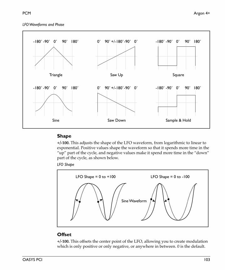
PCM Argon 4+
LFO Waveforms and Phase
Shape+/-100. This adjusts the shape of the LFO waveform, from logarithmic to linear to exponential. Positive values shape the waveform so that it spends more time in the “up” part of the cycle, and negative values make it spend more time in the “down” part of the cycle, as shown below.
LFO Shape
Offset+/-100. This offsets the center point of the LFO, allowing you to create modulation which is only positive or only negative, or anywhere in between. 0 is the default.
0˚ 90˚ 180˚-90˚-180˚
0˚ 90˚ 180˚-90˚-180˚
+/-180˚-90˚ 0˚90˚0˚ 0˚ 90˚ 180˚-90˚-180˚
0˚ 90˚ 180˚-90˚-180˚+/-180˚-90˚ 0˚90˚0˚
Triangle
Sine Saw Down
Saw Up
Sample & Hold
Square
LFO Shape = 0 to +100 LFO Shape = 0 to -100
Sine Waveform
OASYS PCI 103

Argon 4+ PCM
Eng
lish
LFO ControlFrequency Knob, Manual Tempo, MIDI Tempo. The LFO speed can be controlled either by the Frequency knob (including the mod source), the Manual Tempo knob, or by MIDI Tempo (derived from MIDI clocks).
If this is set to Frequency Knob, then the LFO speed will be controlled by the settings in the Frequency section, including the mod source and amount.
If this is set to Manual Tempo, then the Manual Tempo knob will set the basic tempo, and the note value set in the Subdivisions menu will control the LFO speed.
If this is set to MIDI Tempo, then incoming MIDI Clocks will set the basic tempo, and the note value set in the Subdivisions menu will control the LFO speed.
Phase
Initial PhaseThis sets the point in the waveform at which the LFO starts. Whenever the Phase Reset controller is received, the LFO will start from the Initial Phase point.
Phase ResetList of Modulation Sources. This sets the MIDI controller which will reset the LFO’s phase to the Initial Phase point. You can use this to trigger the LFO from a MIDI sequencer, so that it always starts at the same point. This is especially useful in conjunction with MIDI Tempo synchronization. For a complete list of mod sources, please see “Modulation Sources” on page 2.
To make sure that the LFO’s phase is correct when working with a sequencer, it’s best to include the phase reset controller every few bars in the sequence, so that no matter where you start playback, the LFO will be reset appropriately.
FrequencyThe controls in the Frequency section only apply when the LFO Control is set to Frequency Knob.
Frequency0.00-20.00Hz. This controls the speed of the LFO when the LFO Control is set to Frequency Knob.
Frequency ModList of Modulation Sources. This sets the modulation source for controlling the LFO speed. For a complete list, please see “Modulation Sources” on page 2.
Amount+/-20.00Hz. This sets the amount by which the mod source affects the LFO speed.
104 OASYS PCI

PCM Argon 4+
Fade-In0-100. The LFO can be at full level instantly, or can fade in over time after a note is played. This parameter controls how long it takes the LFO to rise to full level after the first note is pressed.
When you release all notes on the keyboard, and then play a new note, the LFO fade-in will start again.
Tempo
Manual Tempo40-240 bpm. This sets the tempo when the LFO Control is set to Manual Tempo.
Subdivision1/32, 1/32 dotted, 1/16, 1/16 dotted, 1/16 triplet, 1/8, 1/8 dotted, 1/8 triplet, 1/4, 1/4 dotted, 1/4 triplet, 1/2, 1/2 dotted, 1/2 triplet, 1 whole note, 2 whole notes. This sets the note value of a single LFO waveform cycle when the LFO Control is set to either Manual Tempo or MIDI Tempo.
Global LFO 2The parameters for Global LFO 2 are the same as those for Global LFO 1, as described above.
OASYS PCI 105

Cobalt 2 PCM
Eng
lish
Cobalt 2Cobalt 2 is a PCM synth plug-in with a two-level velocity-switched multisample, a 2 pole (12dB per octave) lowpass filter, and two DSP-rate ADSR envelopes for filter and amplitude modulation.
Oscillator
SamplesThis Patch lets you use velocity to switch between the two Multisamples. Velocities lower than the Vel Switch setting select the Lo Multisample, and velocities equal to or higher than the Vel Switch setting select the Hi Multisample.
Lo MultisampleThis is the low-velocity Multisample. When a note’s MIDI velocity is lower than the Vel Switch setting. you’ll hear this Multisample.
To select a Multisample:
1. Drag a Multisample from the Catalog onto the desired Multisample slot.
(MacOS Only: Alternatively, you can select the Multisample slot and then double-click the name of the Multisample in the Catalog.)
Double-clicking on the Multisample name brings up the Multisample Edit window.
You can delete a Multisample from a Patch by using the Delete key, or the Edit menu’s cut command.
Hi MultisampleThis is the high-velocity Multisample. When a note’s MIDI velocity is equal to or higher than the Vel Switch setting. you’ll hear this Multisample.
Lo Level0-100. This controls the volume level of the low (Lo) Multisample.
Hi Level0-100. This controls the volume level of the high (Hi) Multisample.
Vel Switch0-127. You can use velocity to switch between the two Multisamples. Velocities lower than the Vel Switch setting will play the Lo Multisample, and velocities equal to or higher than the Vel Switch setting will play the Hi Multisample.
106 OASYS PCI

PCM Cobalt 2
Pitch
Tune+/- 48. This sets the coarse tuning of the oscillator over an eight-octave range, in half-steps.
Fine+/- 100. This sets the fine tuning of the oscillator, in cents (1/100 of a semitone).
Slope+/- 2.00. The Pitch Slope allows you to adjust the way in which the oscillator’s pitch changes as you play higher or lower on your MIDI controller. The slope is centered around middle C (C4).
+1.00 is the default setting; pitch will track the keyboard normally.
Values above +1.00 increasingly stretch the oscillator tuning. In other words, above C4 the oscillator gets increasingly sharp, and below C4 the oscillator gets increasingly flat.
+2.00 means the pitch changes two octaves over only a single octave of MIDI input.
+0.50 means that an octave of pitch is spread out over two octaves of MIDI input, producing a quarter-tone scale.
0.00 makes all notes play at middle C (C4).
A negative Slope value inverts the pitch tracking, so that as you play higher on your controller the pitch gets lower, and vice versa. Normally you would use this adjustment on oscillators that contribute harmonics within a patch, rather than on ones responsible for fundamental pitch.
NOTE: Pitch slope also changes the way that Multisamples are mapped across the keyboard. When you are editing a Multisample in the Multisample Edit window, it’s generally best to make sure that Pitch Slope is set to 1.00.
2 Pole Filter
Filter
Cutoff0-100. This controls the cutoff frequency of the 12dB per octave lowpass filter. Frequencies above the cutoff are cut, and frequencies below the cutoff are passed through unchanged.
Generally speaking, the lower the cutoff, the darker the sound; the higher the cutoff, the brighter the sound.
Note that the Envelope and Key Track parameters also affect the cutoff frequency.
OASYS PCI 107

Cobalt 2 PCM
Eng
lish
This control has extra smoothing on the DSP, to ensure zipper-free modulation. If instantaneous modulation is desired (such as modulation via velocity), modulate the Filter Mod section’s Envelope control instead.
Envelope+/- 100. The ADSR envelope can be used to control the filter cutoff frequency, adding to or subtracting from the setting on the Cutoff knob. With positive envelope amounts, the envelope will increase the cutoff frequency above the setting on the Cutoff knob. With negative amounts, the envelope will act as if it is inverted, decreasing the cutoff frequency below the setting on the Cutoff knob.
At 0, the envelope will have no affect. At +100, the envelope will open the filter all the way at its peak, even if Cutoff is set to 0. At -100, the envelope will close the filter all the way down at its peak, even if the Cutoff is set to 100.
Envelope amount affect on cutoff frequency
Key Tracking
Amount+/- 100. This adjusts the filter cutoff as you play higher and lower on the keyboard. At the center key (as set below), the cutoff will be exactly the value set by the Cutoff knob. With positive tracking, the cutoff will increase as you play above the center key, and decrease as you play below it. With negative tracking, cutoff will decrease as you play above the center key, and increase as you play below it.
Note that you can also modulate any parameter using the “Key Tracking” modulators in the Mod Palette.
+100
-100
0
Enve
lope
am
ount
108 OASYS PCI

PCM Cobalt 2
CenterC-1 to G#9. This sets the key around which the filter tracking is centered.
Envelope
Attack0-100. This sets the attack time of the filter envelope, which controls how long it takes from the moment that the key is pressed until the envelope reaches its peak.
Decay 0-100. This sets the decay time of the filter envelope, which controls how long it takes the envelope to fall to the sustain level after the attack is complete.
Sustain0-100. This sets the sustain level for the filter envelope. After the decay time is complete, the envelope will stay at this level as long as the note is held.
Release0-100. This sets the release time of the filter envelope, which controls how long it takes the envelope to fall to zero after the note is released.
ADSR Envelope
Amplifier
EnvelopeThese parameters control an ADSR envelope dedicated to the output volume. For a graphic explaining ADSR envelopes, see the figure “ADSR Envelope,” above.
Attack time Decay time Release timeSustain while
SustainLevel
holding note
Enve
lope
Am
ount
OASYS PCI 109

Cobalt 2 PCM
Eng
lish
Attack0-100. This sets the attack time of the amplitude envelope, which controls how long it takes from the moment that the key is pressed until the envelope reaches its peak.
Decay 0-100. This sets the decay time of the amplitude envelope, which controls how long it takes the envelope to fall to the sustain level after the attack is complete.
Sustain0-100. This sets the sustain level for the amplitude envelope. After the decay time is complete, the envelope will stay at this level as long as the note is held.
Release0-100. This sets the release time of the amplitude envelope, which controls how long it takes the envelope to fall to zero after the note is released.
Amp Mod
LFO 10.0-100.0. This sets the amount by which LFO 1 modulates amplitude.
LFO 20.0-100.0. This sets the amount by which LFO 2 modulates amplitude.
Volume+12 to -123.9dB, -INF. This is the output volume for the Patch.
IMPORTANT: The output volume provides up to 12dB in gain, so that you can get your signals as hot as possible. However, if filter resonance is high, settings above 0dB may cause clipping.
This control has extra smoothing on the DSP, to ensure zipper-free modulation. If you want to modulate the volume instantaneously via velocity, use the Vel Sens control instead.
Vel Sens (Velocity Sensitivity)0-100. This sets the sensitivity of output volume to velocity. A velocity of 127 will always result in the maximum output level, as set by the Volume control; increasing the Vel Sens will decrease the output volume for low velocities.
110 OASYS PCI

PCM Cobalt 2 St
Cobalt 2 StCobalt 2 is a PCM synth plug-in with stereo oscillator, a two-level velocity-switched multisample, a 2 pole (12dB per octave) lowpass filter, and two DSP-rate ADSR envelopes for filter and amplitude modulation.
Stereo Oscillator
SamplesThis Patch lets you use velocity to switch between the two stereo (or mono) Multisamples. Velocities lower than the Vel Switch setting select the Lo Multisample, and velocities equal to or higher than the Vel Switch setting select the Hi Multisample.
Lo MultisampleThis is the low-velocity Multisample. When a note’s MIDI velocity is lower than the Vel Switch setting. you’ll hear this Multisample.
To select a Multisample:
1. Drag a Multisample from the Catalog onto the desired Multisample slot.
(MacOS Only: Alternatively, you can select the Multisample slot and then double-click the name of the Multisample in the Catalog.)
Double-clicking on the Multisample name brings up the Multisample Edit window.
You can delete a Multisample from a Patch by using the Delete key, or the Edit menu’s cut command.
Hi MultisampleThis is the high-velocity Multisample. When a note’s MIDI velocity is equal to or higher than the Vel Switch setting. you’ll hear this Multisample.
Lo Level0-100. This controls the volume level of the low (Lo) Multisample.
Hi Level0-100. This controls the volume level of the high (Hi) Multisample.
Vel Switch0-127. You can use velocity to switch between the two Multisamples. Velocities lower than the Vel Switch setting will play the Lo Multisample, and velocities equal to or higher than the Vel Switch setting will play the Hi Multisample.
OASYS PCI 111

Cobalt 2 St PCM
Eng
lish
Pitch
Tune+/- 48. This sets the coarse tuning of the oscillator over an eight-octave range, in half-steps.
Fine+/- 100. This sets the fine tuning of the oscillator, in cents (1/100 of a semitone).
Slope+/- 2.00. The Pitch Slope allows you to adjust the way in which the oscillator’s pitch changes as you play higher or lower on your MIDI controller. The slope is centered around middle C (C4).
+1.00 is the default setting; pitch will track the keyboard normally.
Values above +1.00 increasingly stretch the oscillator tuning. In other words, above C4 the oscillator gets increasingly sharp, and below C4 the oscillator gets increasingly flat.
+2.00 means the pitch changes two octaves over only a single octave of MIDI input.
+0.50 means that an octave of pitch is spread out over two octaves of MIDI input, producing a quarter-tone scale.
0.00 makes all notes play at middle C (C4).
A negative Slope value inverts the pitch tracking, so that as you play higher on your controller the pitch gets lower, and vice versa. Normally you would use this adjustment on oscillators that contribute harmonics within a patch, rather than on ones responsible for fundamental pitch.
NOTE: Pitch slope also changes the way that Multisamples are mapped across the keyboard. When you are editing a Multisample in the Multisample Edit window, it’s generally best to make sure that Pitch Slope is set to 1.00.
2 Pole Filter
Filter
Cutoff0-100. This controls the cutoff frequency of the 12dB per octave lowpass filter. Frequencies above the cutoff are cut, and frequencies below the cutoff are passed through unchanged.
Generally speaking, the lower the cutoff, the darker the sound; the higher the cutoff, the brighter the sound.
Note that the Envelope and Key Track parameters also affect the cutoff frequency.
112 OASYS PCI
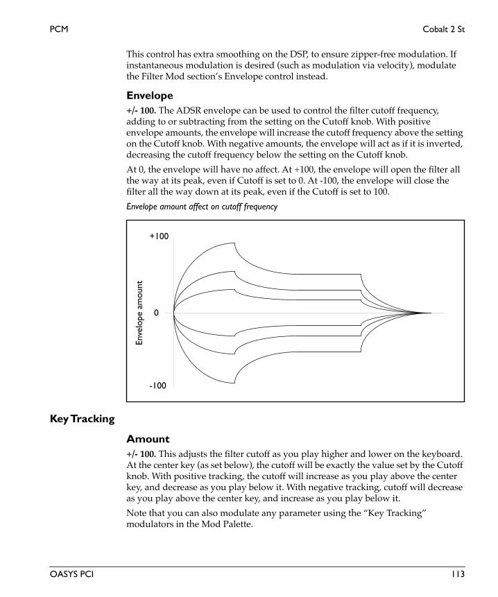
PCM Cobalt 2 St
This control has extra smoothing on the DSP, to ensure zipper-free modulation. If instantaneous modulation is desired (such as modulation via velocity), modulate the Filter Mod section’s Envelope control instead.
Envelope+/- 100. The ADSR envelope can be used to control the filter cutoff frequency, adding to or subtracting from the setting on the Cutoff knob. With positive envelope amounts, the envelope will increase the cutoff frequency above the setting on the Cutoff knob. With negative amounts, the envelope will act as if it is inverted, decreasing the cutoff frequency below the setting on the Cutoff knob.
At 0, the envelope will have no affect. At +100, the envelope will open the filter all the way at its peak, even if Cutoff is set to 0. At -100, the envelope will close the filter all the way down at its peak, even if the Cutoff is set to 100.
Envelope amount affect on cutoff frequency
Key Tracking
Amount+/- 100. This adjusts the filter cutoff as you play higher and lower on the keyboard. At the center key (as set below), the cutoff will be exactly the value set by the Cutoff knob. With positive tracking, the cutoff will increase as you play above the center key, and decrease as you play below it. With negative tracking, cutoff will decrease as you play above the center key, and increase as you play below it.
Note that you can also modulate any parameter using the “Key Tracking” modulators in the Mod Palette.
+100
-100
0
Enve
lope
am
ount
OASYS PCI 113

Cobalt 2 St PCM
Eng
lish
CenterC-1 to G#9. This sets the key around which the filter tracking is centered.
Envelope
Attack0-100. This sets the attack time of the filter envelope, which controls how long it takes from the moment that the key is pressed until the envelope reaches its peak.
Decay 0-100. This sets the decay time of the filter envelope, which controls how long it takes the envelope to fall to the sustain level after the attack is complete.
Sustain0-100. This sets the sustain level for the filter envelope. After the decay time is complete, the envelope will stay at this level as long as the note is held.
Release0-100. This sets the release time of the filter envelope, which controls how long it takes the envelope to fall to zero after the note is released.
ADSR Envelope
Amplifier
EnvelopeThese parameters control an ADSR envelope dedicated to the output volume. For a graphic explaining ADSR envelopes, see the figure “ADSR Envelope,” above.
Attack time Decay time Release timeSustain while
SustainLevel
holding note
Enve
lope
Am
ount
114 OASYS PCI

PCM Cobalt 2 St
Attack0-100. This sets the attack time of the amplitude envelope, which controls how long it takes from the moment that the key is pressed until the envelope reaches its peak.
Decay 0-100. This sets the decay time of the amplitude envelope, which controls how long it takes the envelope to fall to the sustain level after the attack is complete.
Sustain0-100. This sets the sustain level for the amplitude envelope. After the decay time is complete, the envelope will stay at this level as long as the note is held.
Release0-100. This sets the release time of the amplitude envelope, which controls how long it takes the envelope to fall to zero after the note is released.
Amp Mod
LFO 10.0-100.0. This sets the amount by which LFO 1 modulates amplitude.
LFO 20.0-100.0. This sets the amount by which LFO 2 modulates amplitude.
Volume+12 to -123.9dB, -INF. This is the output volume for the Patch.
IMPORTANT: The output volume provides up to 12dB in gain, so that you can get your signals as hot as possible. However, if filter resonance is high, settings above 0dB may cause clipping.
This control has extra smoothing on the DSP, to ensure zipper-free modulation. If you want to modulate the volume instantaneously via velocity, use the Vel Sens control instead.
Vel Sens (Velocity Sensitivity)0-100. This sets the sensitivity of output volume to velocity. A velocity of 127 will always result in the maximum output level, as set by the Volume control; increasing the Vel Sens will decrease the output volume for low velocities.
OASYS PCI 115

Cobalt 4 PCM
Eng
lish
Cobalt 4Cobalt 4 is a PCM synth plug-in with a two-level velocity-switched multisample, a 4 pole (24dB per octave) lowpass filter, and two DSP-rate ADSR envelopes for filter and amplitude modulation.
Oscillator
SamplesThis Patch lets you use velocity to switch between the two Multisamples. Velocities lower than the Vel Switch setting select the Lo Multisample, and velocities equal to or higher than the Vel Switch setting select the Hi Multisample.
Lo MultisampleThis is the low-velocity Multisample. When a note’s MIDI velocity is lower than the Vel Switch setting. you’ll hear this Multisample.
To select a Multisample:
1. Drag a Multisample from the Catalog onto the desired Multisample slot.
(MacOS Only: Alternatively, you can select the Multisample slot and then double-click the name of the Multisample in the Catalog.)
Double-clicking on the Multisample name brings up the Multisample Edit window.
You can delete a Multisample from a Patch by using the Delete key, or the Edit menu’s cut command.
Hi MultisampleThis is the high-velocity Multisample. When a note’s MIDI velocity is equal to or higher than the Vel Switch setting. you’ll hear this Multisample.
Lo Level0-100. This controls the volume level of the low (Lo) Multisample.
Hi Level0-100. This controls the volume level of the high (Hi) Multisample.
Vel Switch0-127. You can use velocity to switch between the two Multisamples. Velocities lower than the Vel Switch setting will play the Lo Multisample, and velocities equal to or higher than the Vel Switch setting will play the Hi Multisample.
116 OASYS PCI

PCM Cobalt 4
Pitch
Tune+/- 48. This sets the coarse tuning of the oscillator over an eight-octave range, in half-steps.
Fine+/- 100. This sets the fine tuning of the oscillator, in cents (1/100 of a semitone).
Slope+/- 2.00. The Pitch Slope allows you to adjust the way in which the oscillator’s pitch changes as you play higher or lower on your MIDI controller. The slope is centered around middle C (C4).
+1.00 is the default setting; pitch will track the keyboard normally.
Values above +1.00 increasingly stretch the oscillator tuning. In other words, above C4 the oscillator gets increasingly sharp, and below C4 the oscillator gets increasingly flat.
+2.00 means the pitch changes two octaves over only a single octave of MIDI input.
+0.50 means that an octave of pitch is spread out over two octaves of MIDI input, producing a quarter-tone scale.
0.00 makes all notes play at middle C (C4).
A negative Slope value inverts the pitch tracking, so that as you play higher on your controller the pitch gets lower, and vice versa. Normally you would use this adjustment on oscillators that contribute harmonics within a patch, rather than on ones responsible for fundamental pitch.
NOTE: Pitch slope also changes the way that Multisamples are mapped across the keyboard. When you are editing a Multisample in the Multisample Edit window, it’s generally best to make sure that Pitch Slope is set to 1.00.
4 Pole Filter
Filter
Cutoff0-100. This controls the cutoff frequency of the 24dB per octave lowpass filter. Frequencies above the cutoff are cut, and frequencies below the cutoff are passed through unchanged.
Generally speaking, the lower the cutoff, the darker the sound; the higher the cutoff, the brighter the sound.
Note that the Envelope and Key Track parameters also affect the cutoff frequency.
OASYS PCI 117
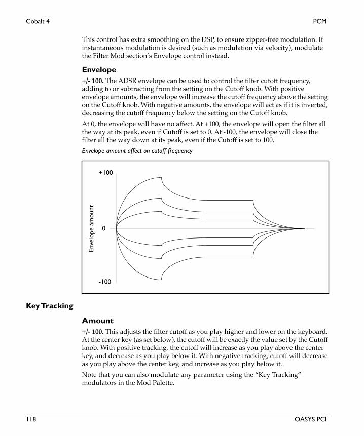
Cobalt 4 PCM
Eng
lish
This control has extra smoothing on the DSP, to ensure zipper-free modulation. If instantaneous modulation is desired (such as modulation via velocity), modulate the Filter Mod section’s Envelope control instead.
Envelope+/- 100. The ADSR envelope can be used to control the filter cutoff frequency, adding to or subtracting from the setting on the Cutoff knob. With positive envelope amounts, the envelope will increase the cutoff frequency above the setting on the Cutoff knob. With negative amounts, the envelope will act as if it is inverted, decreasing the cutoff frequency below the setting on the Cutoff knob.
At 0, the envelope will have no affect. At +100, the envelope will open the filter all the way at its peak, even if Cutoff is set to 0. At -100, the envelope will close the filter all the way down at its peak, even if the Cutoff is set to 100.
Envelope amount affect on cutoff frequency
Key Tracking
Amount+/- 100. This adjusts the filter cutoff as you play higher and lower on the keyboard. At the center key (as set below), the cutoff will be exactly the value set by the Cutoff knob. With positive tracking, the cutoff will increase as you play above the center key, and decrease as you play below it. With negative tracking, cutoff will decrease as you play above the center key, and increase as you play below it.
Note that you can also modulate any parameter using the “Key Tracking” modulators in the Mod Palette.
+100
-100
0
Enve
lope
am
ount
118 OASYS PCI

PCM Cobalt 4
CenterC-1 to G#9. This sets the key around which the filter tracking is centered.
Envelope
Attack0-100. This sets the attack time of the filter envelope, which controls how long it takes from the moment that the key is pressed until the envelope reaches its peak.
Decay 0-100. This sets the decay time of the filter envelope, which controls how long it takes the envelope to fall to the sustain level after the attack is complete.
Sustain0-100. This sets the sustain level for the filter envelope. After the decay time is complete, the envelope will stay at this level as long as the note is held.
Release0-100. This sets the release time of the filter envelope, which controls how long it takes the envelope to fall to zero after the note is released.
ADSR Envelope
Amplifier
EnvelopeThese parameters control an ADSR envelope dedicated to the output volume. For a graphic explaining ADSR envelopes, see the figure “ADSR Envelope,” above.
Attack time Decay time Release timeSustain while
SustainLevel
holding note
Enve
lope
Am
ount
OASYS PCI 119

Cobalt 4 PCM
Eng
lish
Attack0-100. This sets the attack time of the amplitude envelope, which controls how long it takes from the moment that the key is pressed until the envelope reaches its peak.
Decay 0-100. This sets the decay time of the amplitude envelope, which controls how long it takes the envelope to fall to the sustain level after the attack is complete.
Sustain0-100. This sets the sustain level for the amplitude envelope. After the decay time is complete, the envelope will stay at this level as long as the note is held.
Release0-100. This sets the release time of the amplitude envelope, which controls how long it takes the envelope to fall to zero after the note is released.
Amp Mod
LFO 10.0-100.0. This sets the amount by which LFO 1 modulates amplitude.
LFO 20.0-100.0. This sets the amount by which LFO 2 modulates amplitude.
Volume+12 to -123.9dB, -INF. This is the output volume for the Patch.
IMPORTANT: The output volume provides up to 12dB in gain, so that you can get your signals as hot as possible. However, if filter resonance is high, settings above 0dB may cause clipping.
This control has extra smoothing on the DSP, to ensure zipper-free modulation. If you want to modulate the volume instantaneously via velocity, use the Vel Sens control instead.
Vel Sens (Velocity Sensitivity)0-100. This sets the sensitivity of output volume to velocity. A velocity of 127 will always result in the maximum output level, as set by the Volume control; increasing the Vel Sens will decrease the output volume for low velocities.
120 OASYS PCI

PCM Cobalt 4+
Cobalt 4+Cobalt 4+ is a PCM synth plug-in with a two-level velocity-switched multisample, a 4 pole (24dB per octave) resonant lowpass filter, and two DSP-rate ADSR envelopes for filter and amplitude modulation.
Oscillator
SamplesThis Patch lets you use velocity to switch between the two Multisamples. Velocities lower than the Vel Switch setting select the Lo Multisample, and velocities equal to or higher than the Vel Switch setting select the Hi Multisample.
Lo MultisampleThis is the low-velocity Multisample. When a note’s MIDI velocity is lower than the Vel Switch setting. you’ll hear this Multisample.
To select a Multisample:
1. Drag a Multisample from the Catalog onto the desired Multisample slot.
(MacOS Only: Alternatively, you can select the Multisample slot and then double-click the name of the Multisample in the Catalog.)
Double-clicking on the Multisample name brings up the Multisample Edit window.
You can delete a Multisample from a Patch by using the Delete key, or the Edit menu’s cut command.
Hi MultisampleThis is the high-velocity Multisample. When a note’s MIDI velocity is equal to or higher than the Vel Switch setting. you’ll hear this Multisample.
Lo Level0-100. This controls the volume level of the low (Lo) Multisample.
Hi Level0-100. This controls the volume level of the high (Hi) Multisample.
Vel Switch0-127. You can use velocity to switch between the two Multisamples. Velocities lower than the Vel Switch setting will play the Lo Multisample, and velocities equal to or higher than the Vel Switch setting will play the Hi Multisample.
OASYS PCI 121
Cobalt 4+ PCM
Eng
lish
Pitch
Tune+/- 48. This sets the coarse tuning of the oscillator over an eight-octave range, in half-steps.
Fine+/- 100. This sets the fine tuning of the oscillator, in cents (1/100 of a semitone).
Slope+/- 2.00. The Pitch Slope allows you to adjust the way in which the oscillator’s pitch changes as you play higher or lower on your MIDI controller. The slope is centered around middle C (C4).
+1.00 is the default setting; pitch will track the keyboard normally.
Values above +1.00 increasingly stretch the oscillator tuning. In other words, above C4 the oscillator gets increasingly sharp, and below C4 the oscillator gets increasingly flat.
+2.00 means the pitch changes two octaves over only a single octave of MIDI input.
+0.50 means that an octave of pitch is spread out over two octaves of MIDI input, producing a quarter-tone scale.
0.00 makes all notes play at middle C (C4).
A negative Slope value inverts the pitch tracking, so that as you play higher on your controller the pitch gets lower, and vice versa. Normally you would use this adjustment on oscillators that contribute harmonics within a patch, rather than on ones responsible for fundamental pitch.
NOTE: Pitch slope also changes the way that Multisamples are mapped across the keyboard. When you are editing a Multisample in the Multisample Edit window, it’s generally best to make sure that Pitch Slope is set to 1.00.
4 Pole Filter
Filter
Cutoff0-100. This controls the cutoff frequency of the 24dB per octave lowpass filter. Frequencies above the cutoff are cut, and frequencies below the cutoff are passed through unchanged.
Generally speaking, the lower the cutoff, the darker the sound; the higher the cutoff, the brighter the sound.
Note that the Envelope and Key Track parameters also affect the cutoff frequency.
122 OASYS PCI
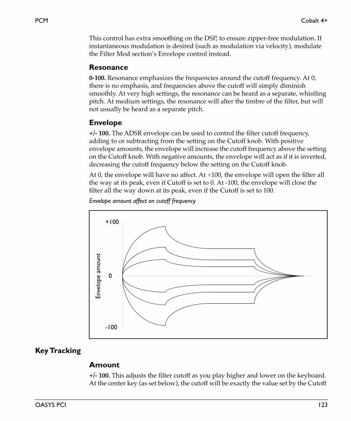
PCM Cobalt 4+
This control has extra smoothing on the DSP, to ensure zipper-free modulation. If instantaneous modulation is desired (such as modulation via velocity), modulate the Filter Mod section’s Envelope control instead.
Resonance0-100. Resonance emphasizes the frequencies around the cutoff frequency. At 0, there is no emphasis, and frequencies above the cutoff will simply diminish smoothly. At very high settings, the resonance can be heard as a separate, whistling pitch. At medium settings, the resonance will alter the timbre of the filter, but will not usually be heard as a separate pitch.
Envelope+/- 100. The ADSR envelope can be used to control the filter cutoff frequency, adding to or subtracting from the setting on the Cutoff knob. With positive envelope amounts, the envelope will increase the cutoff frequency above the setting on the Cutoff knob. With negative amounts, the envelope will act as if it is inverted, decreasing the cutoff frequency below the setting on the Cutoff knob.
At 0, the envelope will have no affect. At +100, the envelope will open the filter all the way at its peak, even if Cutoff is set to 0. At -100, the envelope will close the filter all the way down at its peak, even if the Cutoff is set to 100.
Envelope amount affect on cutoff frequency
Key Tracking
Amount+/- 100. This adjusts the filter cutoff as you play higher and lower on the keyboard. At the center key (as set below), the cutoff will be exactly the value set by the Cutoff
+100
-100
0
Enve
lope
am
ount
OASYS PCI 123

Cobalt 4+ PCM
Eng
lish
knob. With positive tracking, the cutoff will increase as you play above the center key, and decrease as you play below it. With negative tracking, cutoff will decrease as you play above the center key, and increase as you play below it.
Note that you can also modulate any parameter using the “Key Tracking” modulators in the Mod Palette.
CenterC-1 to G#9. This sets the key around which the filter tracking is centered.
Envelope
Attack0-100. This sets the attack time of the filter envelope, which controls how long it takes from the moment that the key is pressed until the envelope reaches its peak.
Decay 0-100. This sets the decay time of the filter envelope, which controls how long it takes the envelope to fall to the sustain level after the attack is complete.
Sustain0-100. This sets the sustain level for the filter envelope. After the decay time is complete, the envelope will stay at this level as long as the note is held.
Release0-100. This sets the release time of the filter envelope, which controls how long it takes the envelope to fall to zero after the note is released.
ADSR Envelope
Attack time Decay time Release timeSustain while
SustainLevel
holding note
Enve
lope
Am
ount
124 OASYS PCI

PCM Cobalt 4+
Amplifier
EnvelopeThese parameters control an ADSR envelope dedicated to the output volume. For a graphic explaining ADSR envelopes, see the figure “ADSR Envelope,” above.
Attack0-100. This sets the attack time of the amplitude envelope, which controls how long it takes from the moment that the key is pressed until the envelope reaches its peak.
Decay 0-100. This sets the decay time of the amplitude envelope, which controls how long it takes the envelope to fall to the sustain level after the attack is complete.
Sustain0-100. This sets the sustain level for the amplitude envelope. After the decay time is complete, the envelope will stay at this level as long as the note is held.
Release0-100. This sets the release time of the amplitude envelope, which controls how long it takes the envelope to fall to zero after the note is released.
Amp Mod
LFO 10.0-100.0. This sets the amount by which LFO 1 modulates amplitude.
LFO 20.0-100.0. This sets the amount by which LFO 2 modulates amplitude.
Volume+12 to -123.9dB, -INF. This is the output volume for the Patch.
IMPORTANT: The output volume provides up to 12dB in gain, so that you can get your signals as hot as possible. However, if filter resonance is high, settings above 0dB may cause clipping.
This control has extra smoothing on the DSP, to ensure zipper-free modulation. If you want to modulate the volume instantaneously via velocity, use the Vel Sens control instead.
Vel Sens (Velocity Sensitivity)0-100. This sets the sensitivity of output volume to velocity. A velocity of 127 will always result in the maximum output level, as set by the Volume control; increasing the Vel Sens will decrease the output volume for low velocities.
OASYS PCI 125

Krypton 2 PCM
Eng
lish
Krypton 2Krypton 2 is a PCM synth plug-in optimized for drums, with a two-level velocity-switched multisample, a 2 pole (12dB per octave) lowpass filter, and a simple, DSP-rate attack-decay envelope.
Oscillator
SamplesThis Patch lets you use velocity to switch between the two Multisamples. Velocities lower than the Vel Switch setting select the Lo Multisample, and velocities equal to or higher than the Vel Switch setting select the Hi Multisample.
Lo MultisampleThis is the low-velocity Multisample. When a note’s MIDI velocity is lower than the Vel Switch setting. you’ll hear this Multisample.
To select a Multisample:
1. Drag a Multisample from the Catalog onto the desired Multisample slot.
(MacOS Only: Alternatively, you can select the Multisample slot and then double-click the name of the Multisample in the Catalog.)
Double-clicking on the Multisample name brings up the Multisample Edit window.
You can delete a Multisample from a Patch by using the Delete key, or the Edit menu’s cut command.
Hi MultisampleThis is the high-velocity Multisample. When a note’s MIDI velocity is equal to or higher than the Vel Switch setting. you’ll hear this Multisample.
Lo Level0-100. This controls the volume level of the low (Lo) Multisample.
Hi Level0-100. This controls the volume level of the high (Hi) Multisample.
Vel Switch0-127. You can use velocity to switch between the two Multisamples. Velocities lower than the Vel Switch setting will play the Lo Multisample, and velocities equal to or higher than the Vel Switch setting will play the Hi Multisample.
126 OASYS PCI

PCM Krypton 2
Pitch
Tune+/- 48. This sets the coarse tuning of the oscillator over an eight-octave range, in half-steps.
Fine+/- 100. This sets the fine tuning of the oscillator, in cents (1/100 of a semitone).
Slope+/- 2.00. The Pitch Slope allows you to adjust the way in which the oscillator’s pitch changes as you play higher or lower on your MIDI controller. The slope is centered around middle C (C4).
+1.00 is the default setting; pitch will track the keyboard normally.
Values above +1.00 increasingly stretch the oscillator tuning. In other words, above C4 the oscillator gets increasingly sharp, and below C4 the oscillator gets increasingly flat.
+2.00 means the pitch changes two octaves over only a single octave of MIDI input.
+0.50 means that an octave of pitch is spread out over two octaves of MIDI input, producing a quarter-tone scale.
0.00 makes all notes play at middle C (C4).
A negative Slope value inverts the pitch tracking, so that as you play higher on your controller the pitch gets lower, and vice versa. Normally you would use this adjustment on oscillators that contribute harmonics within a patch, rather than on ones responsible for fundamental pitch.
NOTE: Pitch slope also changes the way that Multisamples are mapped across the keyboard. When you are editing a Multisample in the Multisample Edit window, it’s generally best to make sure that Pitch Slope is set to 1.00.
2 Pole Filter
Filter
Cutoff0-100. This controls the cutoff frequency of the 12dB per octave lowpass filter. Frequencies above the cutoff are cut, and frequencies below the cutoff are passed through unchanged.
Generally speaking, the lower the cutoff, the darker the sound; the higher the cutoff, the brighter the sound.
OASYS PCI 127

Krypton 2 PCM
Eng
lish
Amplifier
EnvelopeThese parameters control an attack-decay envelope dedicated to the output volume.
Attack0-100. This sets the attack time of the envelope–the time that it takes from the moment that the key is pressed until the envelope reaches its peak.
Decay0-100. This sets the decay time of the envelope–the time that it takes from the moment that the peak of the envelope is reached until the envelope falls to zero.
AR Envelope
Volume+12 to -123.9dB, -INF. This is the output volume for the Patch.
IMPORTANT: The output volume provides up to 12dB in gain, so that you can get your signals as hot as possible. However, if filter resonance is high, settings above 0dB may cause clipping.
This control has extra smoothing on the DSP, to ensure zipper-free modulation. If you want to modulate the volume instantaneously via velocity, use the Vel Sens control instead.
Vel Sens (Velocity Sensitivity)0-100. This sets the sensitivity of output volume to velocity. A velocity of 127 will always result in the maximum output level, as set by the Volume control; increasing the Vel Sens will decrease the output volume for low velocities.
Attack time Decay time
128 OASYS PCI

PCM Krypton 2e
Krypton 2eKrypton 2e is a PCM synth plug-in optimized for drums, with a two-level velocity-switched multisample, a 2 pole (12dB per octave) lowpass filter, output pan, and two DSP-rate attack-decay envelopes for filter and amplitude modulation.
Oscillator
SamplesThis Patch lets you use velocity to switch between the two Multisamples. Velocities lower than the Vel Switch setting select the Lo Multisample, and velocities equal to or higher than the Vel Switch setting select the Hi Multisample.
Lo MultisampleThis is the low-velocity Multisample. When a note’s MIDI velocity is lower than the Vel Switch setting. you’ll hear this Multisample.
To select a Multisample:
1. Drag a Multisample from the Catalog onto the desired Multisample slot.
(MacOS Only: Alternatively, you can select the Multisample slot and then double-click the name of the Multisample in the Catalog.)
Double-clicking on the Multisample name brings up the Multisample Edit window.
You can delete a Multisample from a Patch by using the Delete key, or the Edit menu’s cut command.
Hi MultisampleThis is the high-velocity Multisample. When a note’s MIDI velocity is equal to or higher than the Vel Switch setting. you’ll hear this Multisample.
Lo Level0-100. This controls the volume level of the low (Lo) Multisample.
Hi Level0-100. This controls the volume level of the high (Hi) Multisample.
Vel Switch0-127. You can use velocity to switch between the two Multisamples. Velocities lower than the Vel Switch setting will play the Lo Multisample, and velocities equal to or higher than the Vel Switch setting will play the Hi Multisample.
OASYS PCI 129

Krypton 2e PCM
Eng
lish
Pitch
Tune+/- 48. This sets the coarse tuning of the oscillator over an eight-octave range, in half-steps.
Fine+/- 100. This sets the fine tuning of the oscillator, in cents (1/100 of a semitone).
Slope+/- 2.00. The Pitch Slope allows you to adjust the way in which the oscillator’s pitch changes as you play higher or lower on your MIDI controller. The slope is centered around middle C (C4).
+1.00 is the default setting; pitch will track the keyboard normally.
Values above +1.00 increasingly stretch the oscillator tuning. In other words, above C4 the oscillator gets increasingly sharp, and below C4 the oscillator gets increasingly flat.
+2.00 means the pitch changes two octaves over only a single octave of MIDI input.
+0.50 means that an octave of pitch is spread out over two octaves of MIDI input, producing a quarter-tone scale.
0.00 makes all notes play at middle C (C4).
A negative Slope value inverts the pitch tracking, so that as you play higher on your controller the pitch gets lower, and vice versa. Normally you would use this adjustment on oscillators that contribute harmonics within a patch, rather than on ones responsible for fundamental pitch.
NOTE: Pitch slope also changes the way that Multisamples are mapped across the keyboard. When you are editing a Multisample in the Multisample Edit window, it’s generally best to make sure that Pitch Slope is set to 1.00.
2 Pole Filter
Filter
Cutoff0-100. This controls the cutoff frequency of the 12dB per octave lowpass filter. Frequencies above the cutoff are cut, and frequencies below the cutoff are passed through unchanged.
Generally speaking, the lower the cutoff, the darker the sound; the higher the cutoff, the brighter the sound.
Note that the Envelope and Key Track parameters also affect the cutoff frequency.
130 OASYS PCI

PCM Krypton 2e
This control has extra smoothing on the DSP, to ensure zipper-free modulation. If instantaneous modulation is desired (such as modulation via velocity), modulate the Filter Mod section’s Envelope control instead.
Envelope+/- 100. The attack-decay envelope can be used to control the filter cutoff frequency, adding to or subtracting from the setting on the Cutoff knob. With positive envelope amounts, the envelope will increase the cutoff frequency above the setting on the Cutoff knob. With negative amounts, the envelope will act as if it is inverted, decreasing the cutoff frequency below the setting on the Cutoff knob.
At 0, the envelope will have no affect. At +100, the envelope will open the filter all the way at its peak, even if Cutoff is set to 0. At -100, the envelope will close the filter all the way down at its peak, even if the Cutoff is set to 100.
Key Tracking
Amount+/- 100. This adjusts the filter cutoff as you play higher and lower on the keyboard. At the center key (as set below), the cutoff will be exactly the value set by the Cutoff knob. With positive tracking, the cutoff will increase as you play above the center key, and decrease as you play below it. With negative tracking, cutoff will decrease as you play above the center key, and increase as you play below it.
Note that you can also modulate any parameter using the “Key Tracking” modulators in the Mod Palette.
CenterC-1 to G#9. This sets the key around which the filter tracking is centered.
EnvelopeThese parameters control the attack-decay envelope dedicated to the filter cutoff.
Attack0-100. This sets the attack time of the envelope–the time that it takes from the moment that the key is pressed until the envelope reaches its peak.
Decay0-100. This sets the decay time of the envelope–the time that it takes from the moment that the peak of the envelope is reached until the envelope falls to zero.
OASYS PCI 131

Krypton 2e PCM
Eng
lish
AR Envelope
Amplifier
EnvelopeThese parameters control an attack-decay envelope dedicated to the output volume.
Attack0-100. This sets the attack time of the envelope–the time that it takes from the moment that the key is pressed until the envelope reaches its peak.
Decay0-100. This sets the decay time of the envelope–the time that it takes from the moment that the peak of the envelope is reached until the envelope falls to zero.
Volume+12 to -123.9dB, -INF. This is the output volume for the Patch.
IMPORTANT: The output volume provides up to 12dB in gain, so that you can get your signals as hot as possible. However, if filter resonance is high, settings above 0dB may cause clipping.
This control has extra smoothing on the DSP, to ensure zipper-free modulation. If you want to modulate the volume instantaneously via velocity, use the Vel Sens control instead.
Vel Sens (Velocity Sensitivity)0-100. This sets the sensitivity of output volume to velocity. A velocity of 127 will always result in the maximum output level, as set by the Volume control; increasing the Vel Sens will decrease the output volume for low velocities.
Attack time Decay time
132 OASYS PCI

PCM Krypton 2e
Pan0-127. This sets the output pan of the Patch. The “Use Sample Pan” parameter, below, allows you to vary the pan separately for each Sample in the Multisample.
Use Sample PanOn, Off. When this parameter is on, the per-Sample pan offsets in the Multisample will be added to the Pan setting (above). When this parameter is off, the Multisample pan offsets will not affect the sound.
OASYS PCI 133

Krypton 2p PCM
Eng
lish
Krypton 2pKrypton 2p is a PCM synth plug-in optimized for drums, with a two-level velocity-switched multisample, a 2 pole (12dB per octave) lowpass filter, output pan, and a simple, DSP-rate attack-decay envelope.
Oscillator
SamplesThis Patch lets you use velocity to switch between the two Multisamples. Velocities lower than the Vel Switch setting select the Lo Multisample, and velocities equal to or higher than the Vel Switch setting select the Hi Multisample.
Lo MultisampleThis is the low-velocity Multisample. When a note’s MIDI velocity is lower than the Vel Switch setting. you’ll hear this Multisample.
To select a Multisample:
1. Drag a Multisample from the Catalog onto the desired Multisample slot.
(MacOS Only: Alternatively, you can select the Multisample slot and then double-click the name of the Multisample in the Catalog.)
Double-clicking on the Multisample name brings up the Multisample Edit window.
You can delete a Multisample from a Patch by using the Delete key, or the Edit menu’s cut command.
Hi MultisampleThis is the high-velocity Multisample. When a note’s MIDI velocity is equal to or higher than the Vel Switch setting. you’ll hear this Multisample.
Lo Level0-100. This controls the volume level of the low (Lo) Multisample.
Hi Level0-100. This controls the volume level of the high (Hi) Multisample.
Vel Switch0-127. You can use velocity to switch between the two Multisamples. Velocities lower than the Vel Switch setting will play the Lo Multisample, and velocities equal to or higher than the Vel Switch setting will play the Hi Multisample.
134 OASYS PCI

PCM Krypton 2p
Pitch
Tune+/- 48. This sets the coarse tuning of the oscillator over an eight-octave range, in half-steps.
Fine+/- 100. This sets the fine tuning of the oscillator, in cents (1/100 of a semitone).
Slope+/- 2.00. The Pitch Slope allows you to adjust the way in which the oscillator’s pitch changes as you play higher or lower on your MIDI controller. The slope is centered around middle C (C4).
+1.00 is the default setting; pitch will track the keyboard normally.
Values above +1.00 increasingly stretch the oscillator tuning. In other words, above C4 the oscillator gets increasingly sharp, and below C4 the oscillator gets increasingly flat.
+2.00 means the pitch changes two octaves over only a single octave of MIDI input.
+0.50 means that an octave of pitch is spread out over two octaves of MIDI input, producing a quarter-tone scale.
0.00 makes all notes play at middle C (C4).
A negative Slope value inverts the pitch tracking, so that as you play higher on your controller the pitch gets lower, and vice versa. Normally you would use this adjustment on oscillators that contribute harmonics within a patch, rather than on ones responsible for fundamental pitch.
NOTE: Pitch slope also changes the way that Multisamples are mapped across the keyboard. When you are editing a Multisample in the Multisample Edit window, it’s generally best to make sure that Pitch Slope is set to 1.00.
2 Pole Filter
Filter
Cutoff0-100. This controls the cutoff frequency of the 12dB per octave lowpass filter. Frequencies above the cutoff are cut, and frequencies below the cutoff are passed through unchanged.
Generally speaking, the lower the cutoff, the darker the sound; the higher the cutoff, the brighter the sound.
OASYS PCI 135

Krypton 2p PCM
Eng
lish
Amplifier
EnvelopeThese parameters control an attack-decay envelope dedicated to the output volume.
Attack0-100. This sets the attack time of the envelope–the time that it takes from the moment that the key is pressed until the envelope reaches its peak.
Decay0-100. This sets the decay time of the envelope–the time that it takes from the moment that the peak of the envelope is reached until the envelope falls to zero.
AR Envelope
Volume+12 to -123.9dB, -INF. This is the output volume for the Patch.
IMPORTANT: The output volume provides up to 12dB in gain, so that you can get your signals as hot as possible. However, if filter resonance is high, settings above 0dB may cause clipping.
This control has extra smoothing on the DSP, to ensure zipper-free modulation. If you want to modulate the volume instantaneously via velocity, use the Vel Sens control instead.
Vel Sens (Velocity Sensitivity)0-100. This sets the sensitivity of output volume to velocity. A velocity of 127 will always result in the maximum output level, as set by the Volume control; increasing the Vel Sens will decrease the output volume for low velocities.
Attack time Decay time
136 OASYS PCI

PCM Krypton 2p
Pan0-127. This sets the output pan of the Patch. The “Use Sample Pan” parameter, below, allows you to vary the pan separately for each Sample in the Multisample.
Use Sample PanOn, Off. When this parameter is on, the per-Sample pan offsets in the Multisample will be added to the Pan setting (above). When this parameter is off, the Multisample pan offsets will not affect the sound.
OASYS PCI 137

Looper PCM
Eng
lish
LooperLooper is a PCM synth plug-in optimized for playback of drum loops and simple drum sounds, with a single multisample oscillator and a DSP-rate attack-release envelope.
Oscillator
MultisampleThis is the Multisample assigned to the oscillator.
To select a Multisample:
1. Drag a Multisample from the Catalog onto the desired Multisample slot.
(MacOS Only: Alternatively, you can select the Multisample slot and then double-click the name of the Multisample in the Catalog.)
Double-clicking on the Multisample name brings up the Multisample Edit window.
You can delete a Multisample from a Patch by using the Delete key, or the Edit menu’s cut command.
Pitch
Tune+/- 48. This sets the coarse tuning of the oscillator over an eight-octave range, in half-steps.
Fine+/- 100. This sets the fine tuning of the oscillator, in cents (1/100 of a semitone).
Amplifier
EnvelopeThese parameters control an attack-release envelope dedicated to the output volume.
Attack0-100. This sets the attack time of the envelope–the time that it takes from the moment that the key is pressed until the envelope reaches its peak.
Release0-100. This sets the release time of the envelope, which controls how long it takes the envelope to fall to zero after the note is released.
138 OASYS PCI
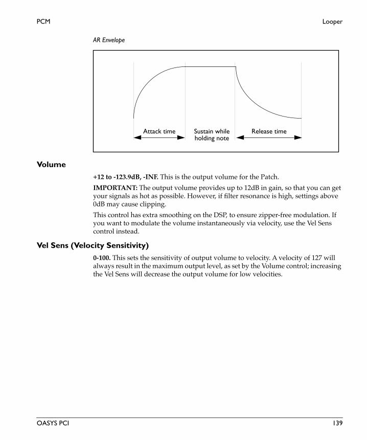
PCM Looper
AR Envelope
Volume+12 to -123.9dB, -INF. This is the output volume for the Patch.
IMPORTANT: The output volume provides up to 12dB in gain, so that you can get your signals as hot as possible. However, if filter resonance is high, settings above 0dB may cause clipping.
This control has extra smoothing on the DSP, to ensure zipper-free modulation. If you want to modulate the volume instantaneously via velocity, use the Vel Sens control instead.
Vel Sens (Velocity Sensitivity)0-100. This sets the sensitivity of output volume to velocity. A velocity of 127 will always result in the maximum output level, as set by the Volume control; increasing the Vel Sens will decrease the output volume for low velocities.
Attack time Release timeSustain whileholding note
OASYS PCI 139

Looper St PCM
Eng
lish
Looper StLooper ST is a PCM synth plug-in optimized for playback of drum loops and simple drum sounds, with a single, stereo oscillator and a DSP-rate attack-release envelope.
Stereo Oscillator
MultisampleThis is the Multisample assigned to the oscillator. This Patch supports both stereo and mono Multisamples.
To select a Multisample:
1. Drag a Multisample from the Catalog onto the desired Multisample slot.
(MacOS Only: Alternatively, you can select the Multisample slot and then double-click the name of the Multisample in the Catalog.)
Double-clicking on the Multisample name brings up the Multisample Edit window.
You can delete a Multisample from a Patch by using the Delete key, or the Edit menu’s cut command.
Pitch
Tune+/- 48. This sets the coarse tuning of the oscillator over an eight-octave range, in half-steps.
Fine+/- 100. This sets the fine tuning of the oscillator, in cents (1/100 of a semitone).
Amplifier
EnvelopeThese parameters control an attack-release envelope dedicated to the output volume.
Attack0-100. This sets the attack time of the envelope–the time that it takes from the moment that the key is pressed until the envelope reaches its peak.
Release0-100. This sets the release time of the envelope, which controls how long it takes the envelope to fall to zero after the note is released.
140 OASYS PCI

PCM Looper St
AR Envelope
Volume+12 to -123.9dB, -INF. This is the output volume for the Patch.
IMPORTANT: The output volume provides up to 12dB in gain, so that you can get your signals as hot as possible. However, if filter resonance is high, settings above 0dB may cause clipping.
This control has extra smoothing on the DSP, to ensure zipper-free modulation. If you want to modulate the volume instantaneously via velocity, use the Vel Sens control instead.
Vel Sens (Velocity Sensitivity)0-100. This sets the sensitivity of output volume to velocity. A velocity of 127 will always result in the maximum output level, as set by the Volume control; increasing the Vel Sens will decrease the output volume for low velocities.
Attack time Release timeSustain whileholding note
OASYS PCI 141

Looper X PCM
Eng
lish
Looper XLooper X is a PCM synth plug-in optimized for playback of drum loops and simple drum sounds, similar to Looper. In addition to a single multisample oscillator and a DSP-rate attack-release envelope, Looper X adds Multisample-controlled output pan.
Oscillator
MultisampleThis is the Multisample assigned to the oscillator.
To select a Multisample:
1. Drag a Multisample from the Catalog onto the desired Multisample slot.
(MacOS Only: Alternatively, you can select the Multisample slot and then double-click the name of the Multisample in the Catalog.)
Double-clicking on the Multisample name brings up the Multisample Edit window.
You can delete a Multisample from a Patch by using the Delete key, or the Edit menu’s cut command.
Pitch
Tune+/- 48. This sets the coarse tuning of the oscillator over an eight-octave range, in half-steps.
Fine+/- 100. This sets the fine tuning of the oscillator, in cents (1/100 of a semitone).
Amplifier
EnvelopeThese parameters control an attack-release envelope dedicated to the output volume.
Attack0-100. This sets the attack time of the envelope–the time that it takes from the moment that the key is pressed until the envelope reaches its peak.
Release0-100. This sets the release time of the envelope, which controls how long it takes the envelope to fall to zero after the note is released.
142 OASYS PCI

PCM Looper X
AR Envelope
Volume+12 to -123.9dB, -INF. This is the output volume for the Patch.
IMPORTANT: The output volume provides up to 12dB in gain, so that you can get your signals as hot as possible. However, if filter resonance is high, settings above 0dB may cause clipping.
This control has extra smoothing on the DSP, to ensure zipper-free modulation. If you want to modulate the volume instantaneously via velocity, use the Vel Sens control instead.
Vel Sens (Velocity Sensitivity)0-100. This sets the sensitivity of output volume to velocity. A velocity of 127 will always result in the maximum output level, as set by the Volume control; increasing the Vel Sens will decrease the output volume for low velocities.
Pan0-127. This sets the output pan of the Patch. The “Use Sample Pan” parameter, below, allows you to vary the pan separately for each Sample in the Multisample.
Use Sample PanOn, Off. When this parameter is on, the per-Sample pan offsets in the Multisample will be added to the Pan setting (above). When this parameter is off, the Multisample pan offsets will not affect the sound.
Attack time Release timeSustain whileholding note
OASYS PCI 143

Xenon 2 PCM
Eng
lish
Xenon 2Xenon 2 is a PCM synth plug-in with a two-level velocity-switched multisample. Features include a 2pole (12dB per octave) resonant lowpass filter, two DSP-rate ADSR envelopes for filter and amplitude modulation, a pitch ramp, and a DSP-rate, complex MIDI-synchronized global LFO.
Oscillator
SamplesThis Patch lets you use velocity to switch between the two Multisamples. Velocities lower than the Vel Switch setting select the Lo Multisample, and velocities equal to or higher than the Vel Switch setting select the Hi Multisample.
Lo MultisampleThis is the low-velocity Multisample. When a note’s MIDI velocity is lower than the Vel Switch setting. you’ll hear this Multisample.
To select a Multisample:
1. Drag a Multisample from the Catalog onto the desired Multisample slot.
(MacOS Only: Alternatively, you can select the Multisample slot and then double-click the name of the Multisample in the Catalog.)
Double-clicking on the Multisample name brings up the Multisample Edit window.
You can delete a Multisample from a Patch by using the Delete key, or the Edit menu’s cut command.
Hi MultisampleThis is the high-velocity Multisample. When a note’s MIDI velocity is equal to or higher than the Vel Switch setting. you’ll hear this Multisample.
Lo Level0-100. This controls the volume level of the low (Lo) Multisample.
Hi Level0-100. This controls the volume level of the high (Hi) Multisample.
Vel Switch0-127. You can use velocity to switch between the two Multisamples. Velocities lower than the Vel Switch setting will play the Lo Multisample, and velocities equal to or higher than the Vel Switch setting will play the Hi Multisample.
144 OASYS PCI

PCM Xenon 2
Pitch
Tune+/- 48. This sets the coarse tuning of the oscillator over an eight-octave range, in half-steps.
Fine+/- 100. This sets the fine tuning of the oscillator, in cents (1/100 of a semitone).
Slope+/- 2.00. The Pitch Slope allows you to adjust the way in which the oscillator’s pitch changes as you play higher or lower on your MIDI controller. The slope is centered around middle C (C4).
+1.00 is the default setting; pitch will track the keyboard normally.
Values above +1.00 increasingly stretch the oscillator tuning. In other words, above C4 the oscillator gets increasingly sharp, and below C4 the oscillator gets increasingly flat.
+2.00 means the pitch changes two octaves over only a single octave of MIDI input.
+0.50 means that an octave of pitch is spread out over two octaves of MIDI input, producing a quarter-tone scale.
0.00 makes all notes play at middle C (C4).
A negative Slope value inverts the pitch tracking, so that as you play higher on your controller the pitch gets lower, and vice versa. Normally you would use this adjustment on oscillators that contribute harmonics within a patch, rather than on ones responsible for fundamental pitch.
NOTE: Pitch slope also changes the way that Multisamples are mapped across the keyboard. When you are editing a Multisample in the Multisample Edit window, it’s generally best to make sure that Pitch Slope is set to 1.00.
Pitch RampThe Pitch Ramp lets you create an automatic pitch-bend at the start of the sound. The pitch-bend can start from either below or above the normal pitch of the note.
Depth +/- 12. This sets the difference between the ramp’s initial pitch and the normal pitch of the key, in half-steps. Set this to 0 to turn off the Pitch Ramp.
Time0-100. This sets the duration of the ramp - the time that it takes the pitch to reach the normal pitch of the key. 0 is the fastest time; 100 is the slowest.
OASYS PCI 145

Xenon 2 PCM
Eng
lish
Pitch Ramp affect on pitch
Pitch Mod
LFO Amt0.0-100.0. This sets the amount by which the LFO modulates pitch.
2 Pole Filter
Filter
Cutoff0-100. This controls the cutoff frequency of the 12dB per octave lowpass filter. Frequencies above the cutoff are cut, and frequencies below the cutoff are passed through unchanged.
Generally speaking, the lower the cutoff, the darker the sound; the higher the cutoff, the brighter the sound.
Note that the Envelope and Key Track parameters also affect the cutoff frequency.
This control has extra smoothing on the DSP, to ensure zipper-free modulation. If instantaneous modulation is desired (such as modulation via velocity), modulate the Filter Mod section’s Envelope control instead.
Resonance0-100. Resonance emphasizes the frequencies around the cutoff frequency. At 0, there is no emphasis, and frequencies above the cutoff will simply diminish smoothly. At very high settings, the resonance can be heard as a separate, whistling
+12.0
-12.0
0
Dep
th
Normal Pitch
Time
146 OASYS PCI

PCM Xenon 2
pitch. At medium settings, the resonance will alter the timbre of the filter, but will not usually be heard as a separate pitch.
Filter Mod
Envelope+/- 100. The ADSR envelope can be used to control the filter cutoff frequency, adding to or subtracting from the setting on the Cutoff knob. With positive envelope amounts, the envelope will increase the cutoff frequency above the setting on the Cutoff knob. With negative amounts, the envelope will act as if it is inverted, decreasing the cutoff frequency below the setting on the Cutoff knob.
At 0, the envelope will have no affect. At +100, the envelope will open the filter all the way at its peak, even if Cutoff is set to 0. At -100, the envelope will close the filter all the way down at its peak, even if the Cutoff is set to 100.
Envelope amount affect on cutoff frequency
LFO Amt+/- 100.0. The LFO can be used to control the filter cutoff frequency, adding to or subtracting from the setting on the Cutoff knob.
Envelope
Attack0-100. This sets the attack time of the filter envelope, which controls how long it takes from the moment that the key is pressed until the envelope reaches its peak.
+100
-100
0
Enve
lope
am
ount
OASYS PCI 147
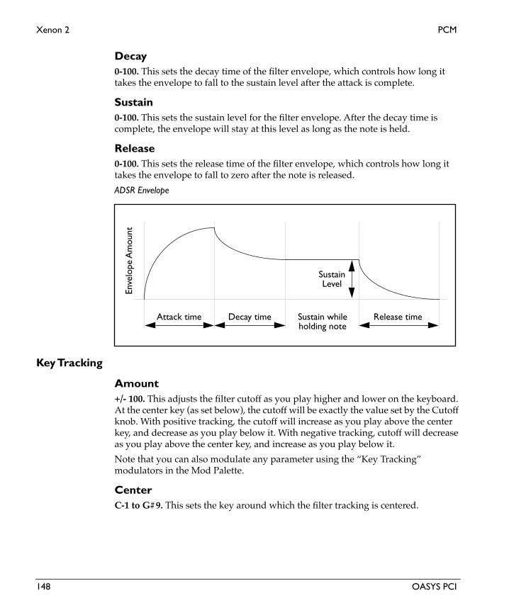
Xenon 2 PCM
Eng
lish
Decay 0-100. This sets the decay time of the filter envelope, which controls how long it takes the envelope to fall to the sustain level after the attack is complete.
Sustain0-100. This sets the sustain level for the filter envelope. After the decay time is complete, the envelope will stay at this level as long as the note is held.
Release0-100. This sets the release time of the filter envelope, which controls how long it takes the envelope to fall to zero after the note is released.
ADSR Envelope
Key Tracking
Amount+/- 100. This adjusts the filter cutoff as you play higher and lower on the keyboard. At the center key (as set below), the cutoff will be exactly the value set by the Cutoff knob. With positive tracking, the cutoff will increase as you play above the center key, and decrease as you play below it. With negative tracking, cutoff will decrease as you play above the center key, and increase as you play below it.
Note that you can also modulate any parameter using the “Key Tracking” modulators in the Mod Palette.
CenterC-1 to G#9. This sets the key around which the filter tracking is centered.
Attack time Decay time Release timeSustain while
SustainLevel
holding note
Enve
lope
Am
ount
148 OASYS PCI

PCM Xenon 2
Amplifier
EnvelopeThese parameters control an ADSR envelope dedicated to the output volume. For a graphic explaining ADSR envelopes, see the figure “ADSR Envelope,” above.
Attack0-100. This sets the attack time of the amplitude envelope, which controls how long it takes from the moment that the key is pressed until the envelope reaches its peak.
Decay 0-100. This sets the decay time of the amplitude envelope, which controls how long it takes the envelope to fall to the sustain level after the attack is complete.
Sustain0-100. This sets the sustain level for the amplitude envelope. After the decay time is complete, the envelope will stay at this level as long as the note is held.
Release0-100. This sets the release time of the amplitude envelope, which controls how long it takes the envelope to fall to zero after the note is released.
Amp Mod
LFO Amt0.0-100.0. This sets the amount by which the LFO modulates amplitude.
Volume+12 to -123.9dB, -INF. This is the output volume for the Patch.
IMPORTANT: The output volume provides up to 12dB in gain, so that you can get your signals as hot as possible. However, if filter resonance is high, settings above 0dB may cause clipping.
This control has extra smoothing on the DSP, to ensure zipper-free modulation. If you want to modulate the volume instantaneously via velocity, use the Vel Sens control instead.
Vel Sens (Velocity Sensitivity)0-100. This sets the sensitivity of output volume to velocity. A velocity of 127 will always result in the maximum output level, as set by the Volume control; increasing the Vel Sens will decrease the output volume for low velocities.
OASYS PCI 149

Xenon 2 PCM
Eng
lish
Global LFO
Waveform
WaveformTriangle, Sine, Saw Up, Saw Down, Square, Sample & Hold. This selects the waveform of the LFO.
LFO Waveforms and Phase
Shape+/-100. This adjusts the shape of the LFO waveform, from logarithmic to linear to exponential. Positive values shape the waveform so that it spends more time in the “up” part of the cycle, and negative values make it spend more time in the “down” part of the cycle, as shown below.
0˚ 90˚ 180˚-90˚-180˚
0˚ 90˚ 180˚-90˚-180˚
+/-180˚-90˚ 0˚90˚0˚ 0˚ 90˚ 180˚-90˚-180˚
0˚ 90˚ 180˚-90˚-180˚+/-180˚-90˚ 0˚90˚0˚
Triangle
Sine Saw Down
Saw Up
Sample & Hold
Square
150 OASYS PCI

PCM Xenon 2
LFO Shape
Offset+/-100. This offsets the center point of the LFO, allowing you to create modulation which is only positive or only negative, or anywhere in between. 0 is the default.
LFO ControlFrequency Knob, Manual Tempo, MIDI Tempo. The LFO speed can be controlled either by the Frequency knob (including the mod source), the Manual Tempo knob, or by MIDI Tempo (derived from MIDI clocks).
If this is set to Frequency Knob, then the LFO speed will be controlled by the settings in the Frequency section, including the mod source and amount.
If this is set to Manual Tempo, then the Manual Tempo knob will set the basic tempo, and the note value set in the Subdivisions menu will control the LFO speed.
If this is set to MIDI Tempo, then incoming MIDI Clocks will set the basic tempo, and the note value set in the Subdivisions menu will control the LFO speed.
Phase
Initial PhaseThis sets the point in the waveform at which the LFO starts. Whenever the Phase Reset controller is received, the LFO will start from the Initial Phase point.
Phase ResetList of Modulation Sources. This sets the MIDI controller which will reset the LFO’s phase to the Initial Phase point. You can use this to trigger the LFO from a MIDI sequencer, so that it always starts at the same point. This is especially useful in conjunction with MIDI Tempo synchronization. For a complete list of mod sources, please see “Modulation Sources” on page 2.
LFO Shape = 0 to +100 LFO Shape = 0 to -100
Sine Waveform
OASYS PCI 151

Xenon 2 PCM
Eng
lish
To make sure that the LFO’s phase is correct when working with a sequencer, it’s best to include the phase reset controller every few bars in the sequence, so that no matter where you start playback, the LFO will be reset appropriately.
FrequencyThe controls in the Frequency section only apply when the LFO Control is set to Frequency Knob.
Frequency0.00-20.00Hz. This controls the speed of the LFO when the LFO Control is set to Frequency Knob.
Frequency ModList of Modulation Sources. This sets the modulation source for controlling the LFO speed. For a complete list, please see “Modulation Sources” on page 2.
Amount+/-20.00Hz. This sets the amount by which the mod source affects the LFO speed.
Tempo
Manual Tempo40-240 bpm. This sets the tempo when the LFO Control is set to Manual Tempo.
Subdivision1/32, 1/32 dotted, 1/16, 1/16 dotted, 1/16 triplet, 1/8, 1/8 dotted, 1/8 triplet, 1/4, 1/4 dotted, 1/4 triplet, 1/2, 1/2 dotted, 1/2 triplet, 1 whole note, 2 whole notes. This sets the note value of a single LFO waveform cycle when the LFO Control is set to either Manual Tempo or MIDI Tempo.
152 OASYS PCI

PCM Xenon 2i
Xenon 2iXenon 2i is similar to Xenon 2, but uses a special, extra-high-quality interpolation method for improved fidelity on high frequencies. Features include a 2pole (12dB per octave) resonant lowpass filter, two DSP-rate ADSR envelopes for filter and amplitude modulation, a pitch ramp, and a DSP-rate, complex MIDI-synchronized global LFO.
Oscillator
SamplesThis Patch lets you use velocity to switch between the two Multisamples. Velocities lower than the Vel Switch setting select the Lo Multisample, and velocities equal to or higher than the Vel Switch setting select the Hi Multisample.
Lo MultisampleThis is the low-velocity Multisample. When a note’s MIDI velocity is lower than the Vel Switch setting. you’ll hear this Multisample.
To select a Multisample:
1. Drag a Multisample from the Catalog onto the desired Multisample slot.
(MacOS Only: Alternatively, you can select the Multisample slot and then double-click the name of the Multisample in the Catalog.)
Double-clicking on the Multisample name brings up the Multisample Edit window.
You can delete a Multisample from a Patch by using the Delete key, or the Edit menu’s cut command.
Hi MultisampleThis is the high-velocity Multisample. When a note’s MIDI velocity is equal to or higher than the Vel Switch setting. you’ll hear this Multisample.
Lo Level0-100. This controls the volume level of the low (Lo) Multisample.
Hi Level0-100. This controls the volume level of the high (Hi) Multisample.
Vel Switch0-127. You can use velocity to switch between the two Multisamples. Velocities lower than the Vel Switch setting will play the Lo Multisample, and velocities equal to or higher than the Vel Switch setting will play the Hi Multisample.
OASYS PCI 153

Xenon 2i PCM
Eng
lish
Pitch
Tune+/- 48. This sets the coarse tuning of the oscillator over an eight-octave range, in half-steps.
Fine+/- 100. This sets the fine tuning of the oscillator, in cents (1/100 of a semitone).
Slope+/- 2.00. The Pitch Slope allows you to adjust the way in which the oscillator’s pitch changes as you play higher or lower on your MIDI controller. The slope is centered around middle C (C4).
+1.00 is the default setting; pitch will track the keyboard normally.
Values above +1.00 increasingly stretch the oscillator tuning. In other words, above C4 the oscillator gets increasingly sharp, and below C4 the oscillator gets increasingly flat.
+2.00 means the pitch changes two octaves over only a single octave of MIDI input.
+0.50 means that an octave of pitch is spread out over two octaves of MIDI input, producing a quarter-tone scale.
0.00 makes all notes play at middle C (C4).
A negative Slope value inverts the pitch tracking, so that as you play higher on your controller the pitch gets lower, and vice versa. Normally you would use this adjustment on oscillators that contribute harmonics within a patch, rather than on ones responsible for fundamental pitch.
NOTE: Pitch slope also changes the way that Multisamples are mapped across the keyboard. When you are editing a Multisample in the Multisample Edit window, it’s generally best to make sure that Pitch Slope is set to 1.00.
Pitch RampThe Pitch Ramp lets you create an automatic pitch-bend at the start of the sound. The pitch-bend can start from either below or above the normal pitch of the note.
Depth +/- 12. This sets the difference between the ramp’s initial pitch and the normal pitch of the key, in half-steps. Set this to 0 to turn off the Pitch Ramp.
Time0-100. This sets the duration of the ramp - the time that it takes the pitch to reach the normal pitch of the key. 0 is the fastest time; 100 is the slowest.
154 OASYS PCI

PCM Xenon 2i
Pitch Ramp affect on pitch
Pitch Mod
LFO Amt0.0-100.0. This sets the amount by which the LFO modulates pitch.
2 Pole Filter
Filter
Cutoff0-100. This controls the cutoff frequency of the 12dB per octave lowpass filter. Frequencies above the cutoff are cut, and frequencies below the cutoff are passed through unchanged.
Generally speaking, the lower the cutoff, the darker the sound; the higher the cutoff, the brighter the sound.
Note that the Envelope and Key Track parameters also affect the cutoff frequency.
This control has extra smoothing on the DSP, to ensure zipper-free modulation. If instantaneous modulation is desired (such as modulation via velocity), modulate the Filter Mod section’s Envelope control instead.
Resonance0-100. Resonance emphasizes the frequencies around the cutoff frequency. At 0, there is no emphasis, and frequencies above the cutoff will simply diminish smoothly. At very high settings, the resonance can be heard as a separate, whistling
+12.0
-12.0
0
Dep
th
Normal Pitch
Time
OASYS PCI 155

Xenon 2i PCM
Eng
lish
pitch. At medium settings, the resonance will alter the timbre of the filter, but will not usually be heard as a separate pitch.
Filter Mod
Envelope+/- 100. The ADSR envelope can be used to control the filter cutoff frequency, adding to or subtracting from the setting on the Cutoff knob. With positive envelope amounts, the envelope will increase the cutoff frequency above the setting on the Cutoff knob. With negative amounts, the envelope will act as if it is inverted, decreasing the cutoff frequency below the setting on the Cutoff knob.
At 0, the envelope will have no affect. At +100, the envelope will open the filter all the way at its peak, even if Cutoff is set to 0. At -100, the envelope will close the filter all the way down at its peak, even if the Cutoff is set to 100.
Envelope amount affect on cutoff frequency
LFO Amt+/- 100.0. The LFO can be used to control the filter cutoff frequency, adding to or subtracting from the setting on the Cutoff knob.
Envelope
Attack0-100. This sets the attack time of the filter envelope, which controls how long it takes from the moment that the key is pressed until the envelope reaches its peak.
+100
-100
0
Enve
lope
am
ount
156 OASYS PCI
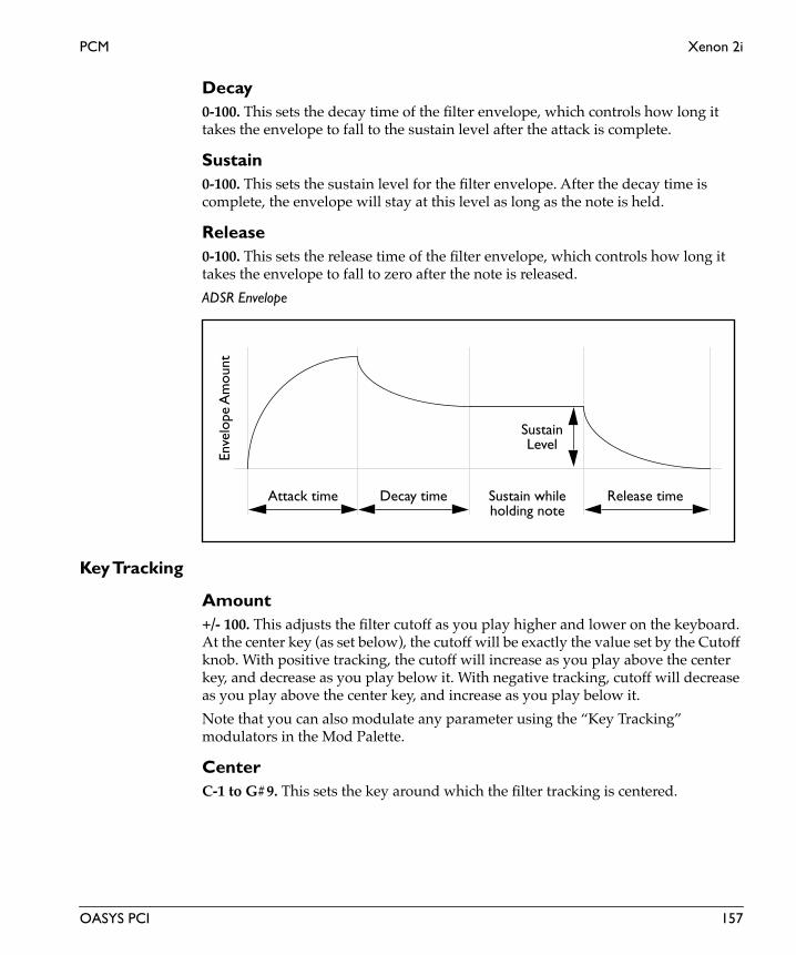
PCM Xenon 2i
Decay 0-100. This sets the decay time of the filter envelope, which controls how long it takes the envelope to fall to the sustain level after the attack is complete.
Sustain0-100. This sets the sustain level for the filter envelope. After the decay time is complete, the envelope will stay at this level as long as the note is held.
Release0-100. This sets the release time of the filter envelope, which controls how long it takes the envelope to fall to zero after the note is released.
ADSR Envelope
Key Tracking
Amount+/- 100. This adjusts the filter cutoff as you play higher and lower on the keyboard. At the center key (as set below), the cutoff will be exactly the value set by the Cutoff knob. With positive tracking, the cutoff will increase as you play above the center key, and decrease as you play below it. With negative tracking, cutoff will decrease as you play above the center key, and increase as you play below it.
Note that you can also modulate any parameter using the “Key Tracking” modulators in the Mod Palette.
CenterC-1 to G#9. This sets the key around which the filter tracking is centered.
Attack time Decay time Release timeSustain while
SustainLevel
holding note
Enve
lope
Am
ount
OASYS PCI 157

Xenon 2i PCM
Eng
lish
Amplifier
EnvelopeThese parameters control an ADSR envelope dedicated to the output volume. For a graphic explaining ADSR envelopes, see the figure “ADSR Envelope,” above.
Attack0-100. This sets the attack time of the amplitude envelope, which controls how long it takes from the moment that the key is pressed until the envelope reaches its peak.
Decay 0-100. This sets the decay time of the amplitude envelope, which controls how long it takes the envelope to fall to the sustain level after the attack is complete.
Sustain0-100. This sets the sustain level for the amplitude envelope. After the decay time is complete, the envelope will stay at this level as long as the note is held.
Release0-100. This sets the release time of the amplitude envelope, which controls how long it takes the envelope to fall to zero after the note is released.
Amp Mod
LFO Amt0.0-100.0. This sets the amount by which the LFO modulates amplitude.
Volume+12 to -123.9dB, -INF. This is the output volume for the Patch.
IMPORTANT: The output volume provides up to 12dB in gain, so that you can get your signals as hot as possible. However, if filter resonance is high, settings above 0dB may cause clipping.
This control has extra smoothing on the DSP, to ensure zipper-free modulation. If you want to modulate the volume instantaneously via velocity, use the Vel Sens control instead.
Vel Sens (Velocity Sensitivity)0-100. This sets the sensitivity of output volume to velocity. A velocity of 127 will always result in the maximum output level, as set by the Volume control; increasing the Vel Sens will decrease the output volume for low velocities.
158 OASYS PCI

PCM Xenon 2i
Global LFO
Waveform
WaveformTriangle, Sine, Saw Up, Saw Down, Square, Sample & Hold. This selects the waveform of the LFO.
LFO Waveforms and Phase
Shape+/-100. This adjusts the shape of the LFO waveform, from logarithmic to linear to exponential. Positive values shape the waveform so that it spends more time in the “up” part of the cycle, and negative values make it spend more time in the “down” part of the cycle, as shown below.
0˚ 90˚ 180˚-90˚-180˚
0˚ 90˚ 180˚-90˚-180˚
+/-180˚-90˚ 0˚90˚0˚ 0˚ 90˚ 180˚-90˚-180˚
0˚ 90˚ 180˚-90˚-180˚+/-180˚-90˚ 0˚90˚0˚
Triangle
Sine Saw Down
Saw Up
Sample & Hold
Square
OASYS PCI 159

Xenon 2i PCM
Eng
lish
LFO Shape
Offset+/-100. This offsets the center point of the LFO, allowing you to create modulation which is only positive or only negative, or anywhere in between. 0 is the default.
LFO ControlFrequency Knob, Manual Tempo, MIDI Tempo. The LFO speed can be controlled either by the Frequency knob (including the mod source), the Manual Tempo knob, or by MIDI Tempo (derived from MIDI clocks).
If this is set to Frequency Knob, then the LFO speed will be controlled by the settings in the Frequency section, including the mod source and amount.
If this is set to Manual Tempo, then the Manual Tempo knob will set the basic tempo, and the note value set in the Subdivisions menu will control the LFO speed.
If this is set to MIDI Tempo, then incoming MIDI Clocks will set the basic tempo, and the note value set in the Subdivisions menu will control the LFO speed.
Phase
Initial PhaseThis sets the point in the waveform at which the LFO starts. Whenever the Phase Reset controller is received, the LFO will start from the Initial Phase point.
Phase ResetList of Modulation Sources. This sets the MIDI controller which will reset the LFO’s phase to the Initial Phase point. You can use this to trigger the LFO from a MIDI sequencer, so that it always starts at the same point. This is especially useful in conjunction with MIDI Tempo synchronization. For a complete list of mod sources, please see “Modulation Sources” on page 2.
LFO Shape = 0 to +100 LFO Shape = 0 to -100
Sine Waveform
160 OASYS PCI

PCM Xenon 2i
To make sure that the LFO’s phase is correct when working with a sequencer, it’s best to include the phase reset controller every few bars in the sequence, so that no matter where you start playback, the LFO will be reset appropriately.
FrequencyThe controls in the Frequency section only apply when the LFO Control is set to Frequency Knob.
Frequency0.00-20.00Hz. This controls the speed of the LFO when the LFO Control is set to Frequency Knob.
Frequency ModList of Modulation Sources. This sets the modulation source for controlling the LFO speed. For a complete list, please see “Modulation Sources” on page 2.
Amount+/-20.00Hz. This sets the amount by which the mod source affects the LFO speed.
Tempo
Manual Tempo40-240 bpm. This sets the tempo when the LFO Control is set to Manual Tempo.
Subdivision1/32, 1/32 dotted, 1/16, 1/16 dotted, 1/16 triplet, 1/8, 1/8 dotted, 1/8 triplet, 1/4, 1/4 dotted, 1/4 triplet, 1/2, 1/2 dotted, 1/2 triplet, 1 whole note, 2 whole notes. This sets the note value of a single LFO waveform cycle when the LFO Control is set to either Manual Tempo or MIDI Tempo.
OASYS PCI 161

Xenon 4 PCM
Eng
lish
Xenon 4Xenon 4 is a PCM synth plug-in with a two-level velocity-switched multisample. Features include a 4 pole (24dB per octave) lowpass filter, two DSP-rate ADSR envelopes for filter and amplitude modulation, a pitch ramp, and a DSP-rate, complex MIDI-synchronized global LFO.
Oscillator
SamplesThis Patch lets you use velocity to switch between the two Multisamples. Velocities lower than the Vel Switch setting select the Lo Multisample, and velocities equal to or higher than the Vel Switch setting select the Hi Multisample.
Lo MultisampleThis is the low-velocity Multisample. When a note’s MIDI velocity is lower than the Vel Switch setting. you’ll hear this Multisample.
To select a Multisample:
1. Drag a Multisample from the Catalog onto the desired Multisample slot.
(MacOS Only: Alternatively, you can select the Multisample slot and then double-click the name of the Multisample in the Catalog.)
Double-clicking on the Multisample name brings up the Multisample Edit window.
You can delete a Multisample from a Patch by using the Delete key, or the Edit menu’s cut command.
Hi MultisampleThis is the high-velocity Multisample. When a note’s MIDI velocity is equal to or higher than the Vel Switch setting. you’ll hear this Multisample.
Lo Level0-100. This controls the volume level of the low (Lo) Multisample.
Hi Level0-100. This controls the volume level of the high (Hi) Multisample.
Vel Switch0-127. You can use velocity to switch between the two Multisamples. Velocities lower than the Vel Switch setting will play the Lo Multisample, and velocities equal to or higher than the Vel Switch setting will play the Hi Multisample.
162 OASYS PCI

PCM Xenon 4
Pitch
Tune+/- 48. This sets the coarse tuning of the oscillator over an eight-octave range, in half-steps.
Fine+/- 100. This sets the fine tuning of the oscillator, in cents (1/100 of a semitone).
Slope+/- 2.00. The Pitch Slope allows you to adjust the way in which the oscillator’s pitch changes as you play higher or lower on your MIDI controller. The slope is centered around middle C (C4).
+1.00 is the default setting; pitch will track the keyboard normally.
Values above +1.00 increasingly stretch the oscillator tuning. In other words, above C4 the oscillator gets increasingly sharp, and below C4 the oscillator gets increasingly flat.
+2.00 means the pitch changes two octaves over only a single octave of MIDI input.
+0.50 means that an octave of pitch is spread out over two octaves of MIDI input, producing a quarter-tone scale.
0.00 makes all notes play at middle C (C4).
A negative Slope value inverts the pitch tracking, so that as you play higher on your controller the pitch gets lower, and vice versa. Normally you would use this adjustment on oscillators that contribute harmonics within a patch, rather than on ones responsible for fundamental pitch.
NOTE: Pitch slope also changes the way that Multisamples are mapped across the keyboard. When you are editing a Multisample in the Multisample Edit window, it’s generally best to make sure that Pitch Slope is set to 1.00.
Pitch RampThe Pitch Ramp lets you create an automatic pitch-bend at the start of the sound. The pitch-bend can start from either below or above the normal pitch of the note.
Depth +/- 12. This sets the difference between the ramp’s initial pitch and the normal pitch of the key, in half-steps. Set this to 0 to turn off the Pitch Ramp.
Time0-100. This sets the duration of the ramp - the time that it takes the pitch to reach the normal pitch of the key. 0 is the fastest time; 100 is the slowest.
OASYS PCI 163

Xenon 4 PCM
Eng
lish
Pitch Ramp affect on pitch
Pitch Mod
LFO Amt0.0-100.0. This sets the amount by which the LFO modulates pitch.
4 Pole Filter
Filter
Cutoff0-100. This controls the cutoff frequency of the 24dB per octave lowpass filter. Frequencies above the cutoff are cut, and frequencies below the cutoff are passed through unchanged.
Generally speaking, the lower the cutoff, the darker the sound; the higher the cutoff, the brighter the sound.
Note that the Envelope and Key Track parameters also affect the cutoff frequency.
This control has extra smoothing on the DSP, to ensure zipper-free modulation. If instantaneous modulation is desired (such as modulation via velocity), modulate the Filter Mod section’s Envelope control instead.
Filter Mod
Envelope+/- 100. The ADSR envelope can be used to control the filter cutoff frequency, adding to or subtracting from the setting on the Cutoff knob. With positive
+12.0
-12.0
0
Dep
th
Normal Pitch
Time
164 OASYS PCI

PCM Xenon 4
envelope amounts, the envelope will increase the cutoff frequency above the setting on the Cutoff knob. With negative amounts, the envelope will act as if it is inverted, decreasing the cutoff frequency below the setting on the Cutoff knob.
At 0, the envelope will have no affect. At +100, the envelope will open the filter all the way at its peak, even if Cutoff is set to 0. At -100, the envelope will close the filter all the way down at its peak, even if the Cutoff is set to 100.
Envelope amount affect on cutoff frequency
LFO Amt+/- 100.0. The LFO can be used to control the filter cutoff frequency, adding to or subtracting from the setting on the Cutoff knob.
Envelope
Attack0-100. This sets the attack time of the filter envelope, which controls how long it takes from the moment that the key is pressed until the envelope reaches its peak.
Decay 0-100. This sets the decay time of the filter envelope, which controls how long it takes the envelope to fall to the sustain level after the attack is complete.
Sustain0-100. This sets the sustain level for the filter envelope. After the decay time is complete, the envelope will stay at this level as long as the note is held.
+100
-100
0
Enve
lope
am
ount
OASYS PCI 165

Xenon 4 PCM
Eng
lish
Release0-100. This sets the release time of the filter envelope, which controls how long it takes the envelope to fall to zero after the note is released.
ADSR Envelope
Key Tracking
Amount+/- 100. This adjusts the filter cutoff as you play higher and lower on the keyboard. At the center key (as set below), the cutoff will be exactly the value set by the Cutoff knob. With positive tracking, the cutoff will increase as you play above the center key, and decrease as you play below it. With negative tracking, cutoff will decrease as you play above the center key, and increase as you play below it.
Note that you can also modulate any parameter using the “Key Tracking” modulators in the Mod Palette.
CenterC-1 to G#9. This sets the key around which the filter tracking is centered.
Amplifier
EnvelopeThese parameters control an ADSR envelope dedicated to the output volume. For a graphic explaining ADSR envelopes, see the figure “ADSR Envelope,” above.
Attack0-100. This sets the attack time of the amplitude envelope, which controls how long it takes from the moment that the key is pressed until the envelope reaches its peak.
Attack time Decay time Release timeSustain while
SustainLevel
holding note
Enve
lope
Am
ount
166 OASYS PCI

PCM Xenon 4
Decay 0-100. This sets the decay time of the amplitude envelope, which controls how long it takes the envelope to fall to the sustain level after the attack is complete.
Sustain0-100. This sets the sustain level for the amplitude envelope. After the decay time is complete, the envelope will stay at this level as long as the note is held.
Release0-100. This sets the release time of the amplitude envelope, which controls how long it takes the envelope to fall to zero after the note is released.
Amp Mod
LFO Amt0.0-100.0. This sets the amount by which the LFO modulates amplitude.
Volume+12 to -123.9dB, -INF. This is the output volume for the Patch.
IMPORTANT: The output volume provides up to 12dB in gain, so that you can get your signals as hot as possible. However, if filter resonance is high, settings above 0dB may cause clipping.
This control has extra smoothing on the DSP, to ensure zipper-free modulation. If you want to modulate the volume instantaneously via velocity, use the Vel Sens control instead.
Vel Sens (Velocity Sensitivity)0-100. This sets the sensitivity of output volume to velocity. A velocity of 127 will always result in the maximum output level, as set by the Volume control; increasing the Vel Sens will decrease the output volume for low velocities.
Global LFO
Waveform
WaveformTriangle, Sine, Saw Up, Saw Down, Square, Sample & Hold. This selects the waveform of the LFO.
OASYS PCI 167

Xenon 4 PCM
Eng
lish
LFO Waveforms and Phase
Shape+/-100. This adjusts the shape of the LFO waveform, from logarithmic to linear to exponential. Positive values shape the waveform so that it spends more time in the “up” part of the cycle, and negative values make it spend more time in the “down” part of the cycle, as shown below.
LFO Shape
Offset+/-100. This offsets the center point of the LFO, allowing you to create modulation which is only positive or only negative, or anywhere in between. 0 is the default.
0˚ 90˚ 180˚-90˚-180˚
0˚ 90˚ 180˚-90˚-180˚
+/-180˚-90˚ 0˚90˚0˚ 0˚ 90˚ 180˚-90˚-180˚
0˚ 90˚ 180˚-90˚-180˚+/-180˚-90˚ 0˚90˚0˚
Triangle
Sine Saw Down
Saw Up
Sample & Hold
Square
LFO Shape = 0 to +100 LFO Shape = 0 to -100
Sine Waveform
168 OASYS PCI

PCM Xenon 4
LFO ControlFrequency Knob, Manual Tempo, MIDI Tempo. The LFO speed can be controlled either by the Frequency knob (including the mod source), the Manual Tempo knob, or by MIDI Tempo (derived from MIDI clocks).
If this is set to Frequency Knob, then the LFO speed will be controlled by the settings in the Frequency section, including the mod source and amount.
If this is set to Manual Tempo, then the Manual Tempo knob will set the basic tempo, and the note value set in the Subdivisions menu will control the LFO speed.
If this is set to MIDI Tempo, then incoming MIDI Clocks will set the basic tempo, and the note value set in the Subdivisions menu will control the LFO speed.
Phase
Initial PhaseThis sets the point in the waveform at which the LFO starts. Whenever the Phase Reset controller is received, the LFO will start from the Initial Phase point.
Phase ResetList of Modulation Sources. This sets the MIDI controller which will reset the LFO’s phase to the Initial Phase point. You can use this to trigger the LFO from a MIDI sequencer, so that it always starts at the same point. This is especially useful in conjunction with MIDI Tempo synchronization. For a complete list of mod sources, please see “Modulation Sources” on page 2.
To make sure that the LFO’s phase is correct when working with a sequencer, it’s best to include the phase reset controller every few bars in the sequence, so that no matter where you start playback, the LFO will be reset appropriately.
FrequencyThe controls in the Frequency section only apply when the LFO Control is set to Frequency Knob.
Frequency0.00-20.00Hz. This controls the speed of the LFO when the LFO Control is set to Frequency Knob.
Frequency ModList of Modulation Sources. This sets the modulation source for controlling the LFO speed. For a complete list, please see “Modulation Sources” on page 2.
Amount+/-20.00Hz. This sets the amount by which the mod source affects the LFO speed.
OASYS PCI 169

Xenon 4 PCM
Eng
lish
Tempo
Manual Tempo40-240 bpm. This sets the tempo when the LFO Control is set to Manual Tempo.
Subdivision1/32, 1/32 dotted, 1/16, 1/16 dotted, 1/16 triplet, 1/8, 1/8 dotted, 1/8 triplet, 1/4, 1/4 dotted, 1/4 triplet, 1/2, 1/2 dotted, 1/2 triplet, 1 whole note, 2 whole notes. This sets the note value of a single LFO waveform cycle when the LFO Control is set to either Manual Tempo or MIDI Tempo.
170 OASYS PCI

PCM Xenon 4+
Xenon 4+Xenon 4+ is a PCM synth plug-in with a two-level velocity-switched multisample. Features include a 4 pole (24dB per octave) resonant lowpass filter, two DSP-rate ADSR envelopes for filter and amplitude modulation, a pitch ramp, and two DSP-rate, complex MIDI-synchronized global LFOs.
Oscillator
SamplesThis Patch lets you use velocity to switch between the two Multisamples. Velocities lower than the Vel Switch setting select the Lo Multisample, and velocities equal to or higher than the Vel Switch setting select the Hi Multisample.
Lo MultisampleThis is the low-velocity Multisample. When a note’s MIDI velocity is lower than the Vel Switch setting. you’ll hear this Multisample.
To select a Multisample:
1. Drag a Multisample from the Catalog onto the desired Multisample slot.
(MacOS Only: Alternatively, you can select the Multisample slot and then double-click the name of the Multisample in the Catalog.)
Double-clicking on the Multisample name brings up the Multisample Edit window.
You can delete a Multisample from a Patch by using the Delete key, or the Edit menu’s cut command.
Hi MultisampleThis is the high-velocity Multisample. When a note’s MIDI velocity is equal to or higher than the Vel Switch setting. you’ll hear this Multisample.
Lo Level0-100. This controls the volume level of the low (Lo) Multisample.
Hi Level0-100. This controls the volume level of the high (Hi) Multisample.
Vel Switch0-127. You can use velocity to switch between the two Multisamples. Velocities lower than the Vel Switch setting will play the Lo Multisample, and velocities equal to or higher than the Vel Switch setting will play the Hi Multisample.
OASYS PCI 171

Xenon 4+ PCM
Eng
lish
Pitch
Tune+/- 48. This sets the coarse tuning of the oscillator over an eight-octave range, in half-steps.
Fine+/- 100. This sets the fine tuning of the oscillator, in cents (1/100 of a semitone).
Slope+/- 2.00. The Pitch Slope allows you to adjust the way in which the oscillator’s pitch changes as you play higher or lower on your MIDI controller. The slope is centered around middle C (C4).
+1.00 is the default setting; pitch will track the keyboard normally.
Values above +1.00 increasingly stretch the oscillator tuning. In other words, above C4 the oscillator gets increasingly sharp, and below C4 the oscillator gets increasingly flat.
+2.00 means the pitch changes two octaves over only a single octave of MIDI input.
+0.50 means that an octave of pitch is spread out over two octaves of MIDI input, producing a quarter-tone scale.
0.00 makes all notes play at middle C (C4).
A negative Slope value inverts the pitch tracking, so that as you play higher on your controller the pitch gets lower, and vice versa. Normally you would use this adjustment on oscillators that contribute harmonics within a patch, rather than on ones responsible for fundamental pitch.
NOTE: Pitch slope also changes the way that Multisamples are mapped across the keyboard. When you are editing a Multisample in the Multisample Edit window, it’s generally best to make sure that Pitch Slope is set to 1.00.
Pitch RampThe Pitch Ramp lets you create an automatic pitch-bend at the start of the sound. The pitch-bend can start from either below or above the normal pitch of the note.
Depth +/- 12. This sets the difference between the ramp’s initial pitch and the normal pitch of the key, in half-steps. Set this to 0 to turn off the Pitch Ramp.
Time0-100. This sets the duration of the ramp - the time that it takes the pitch to reach the normal pitch of the key. 0 is the fastest time; 100 is the slowest.
172 OASYS PCI

PCM Xenon 4+
Pitch Ramp affect on pitch
Pitch Mod
LFO 10.0-100.0. This sets the amount by which LFO 1 modulates pitch.
LFO 20.0-100.0. This sets the amount by which LFO 2 modulates pitch.
4 Pole Filter
Filter
Cutoff0-100. This controls the cutoff frequency of the 24dB per octave lowpass filter. Frequencies above the cutoff are cut, and frequencies below the cutoff are passed through unchanged.
Generally speaking, the lower the cutoff, the darker the sound; the higher the cutoff, the brighter the sound.
Note that the Envelope and Key Track parameters also affect the cutoff frequency.
This control has extra smoothing on the DSP, to ensure zipper-free modulation. If instantaneous modulation is desired (such as modulation via velocity), modulate the Filter Mod section’s Envelope control instead.
+12.0
-12.0
0
Dep
th
Normal Pitch
Time
OASYS PCI 173

Xenon 4+ PCM
Eng
lish
Resonance0-100. Resonance emphasizes the frequencies around the cutoff frequency. At 0, there is no emphasis, and frequencies above the cutoff will simply diminish smoothly. At very high settings, the resonance can be heard as a separate, whistling pitch. At medium settings, the resonance will alter the timbre of the filter, but will not usually be heard as a separate pitch.
Filter Mod
Envelope+/- 100. The ADSR envelope can be used to control the filter cutoff frequency, adding to or subtracting from the setting on the Cutoff knob. With positive envelope amounts, the envelope will increase the cutoff frequency above the setting on the Cutoff knob. With negative amounts, the envelope will act as if it is inverted, decreasing the cutoff frequency below the setting on the Cutoff knob.
At 0, the envelope will have no affect. At +100, the envelope will open the filter all the way at its peak, even if Cutoff is set to 0. At -100, the envelope will close the filter all the way down at its peak, even if the Cutoff is set to 100.
Envelope amount affect on cutoff frequency
LFO 1+/- 100.0. LFO 1 can be used to control the filter cutoff frequency, adding to or subtracting from the setting on the Cutoff knob.
LFO 2+/- 100.0. LFO 2 can be used to control the filter cutoff frequency, adding to or subtracting from the setting on the Cutoff knob.
+100
-100
0
Enve
lope
am
ount
174 OASYS PCI

PCM Xenon 4+
Envelope
Attack0-100. This sets the attack time of the filter envelope, which controls how long it takes from the moment that the key is pressed until the envelope reaches its peak.
Decay 0-100. This sets the decay time of the filter envelope, which controls how long it takes the envelope to fall to the sustain level after the attack is complete.
Sustain0-100. This sets the sustain level for the filter envelope. After the decay time is complete, the envelope will stay at this level as long as the note is held.
Release0-100. This sets the release time of the filter envelope, which controls how long it takes the envelope to fall to zero after the note is released.
ADSR Envelope
Key Tracking
Amount+/- 100. This adjusts the filter cutoff as you play higher and lower on the keyboard. At the center key (as set below), the cutoff will be exactly the value set by the Cutoff knob. With positive tracking, the cutoff will increase as you play above the center key, and decrease as you play below it. With negative tracking, cutoff will decrease as you play above the center key, and increase as you play below it.
Note that you can also modulate any parameter using the “Key Tracking” modulators in the Mod Palette.
Attack time Decay time Release timeSustain while
SustainLevel
holding note
Enve
lope
Am
ount
OASYS PCI 175

Xenon 4+ PCM
Eng
lish
CenterC-1 to G#9. This sets the key around which the filter tracking is centered.
Amplifier
EnvelopeThese parameters control an ADSR envelope dedicated to the output volume. For a graphic explaining ADSR envelopes, see the figure “ADSR Envelope,” above.
Attack0-100. This sets the attack time of the amplitude envelope, which controls how long it takes from the moment that the key is pressed until the envelope reaches its peak.
Decay 0-100. This sets the decay time of the amplitude envelope, which controls how long it takes the envelope to fall to the sustain level after the attack is complete.
Sustain0-100. This sets the sustain level for the amplitude envelope. After the decay time is complete, the envelope will stay at this level as long as the note is held.
Release0-100. This sets the release time of the amplitude envelope, which controls how long it takes the envelope to fall to zero after the note is released.
Amp Mod
LFO 10.0-100.0. This sets the amount by which LFO 1 modulates amplitude.
LFO 20.0-100.0. This sets the amount by which LFO 2 modulates amplitude.
Volume+12 to -123.9dB, -INF. This is the output volume for the Patch.
IMPORTANT: The output volume provides up to 12dB in gain, so that you can get your signals as hot as possible. However, if filter resonance is high, settings above 0dB may cause clipping.
This control has extra smoothing on the DSP, to ensure zipper-free modulation. If you want to modulate the volume instantaneously via velocity, use the Vel Sens control instead.
176 OASYS PCI

PCM Xenon 4+
Vel Sens (Velocity Sensitivity)0-100. This sets the sensitivity of output volume to velocity. A velocity of 127 will always result in the maximum output level, as set by the Volume control; increasing the Vel Sens will decrease the output volume for low velocities.
Global LFO 1
Waveform
WaveformTriangle, Sine, Saw Up, Saw Down, Square, Sample & Hold. This selects the waveform of the LFO.
LFO Waveforms and Phase
Shape+/-100. This adjusts the shape of the LFO waveform, from logarithmic to linear to exponential. Positive values shape the waveform so that it spends more time in the “up” part of the cycle, and negative values make it spend more time in the “down” part of the cycle, as shown below.
0˚ 90˚ 180˚-90˚-180˚
0˚ 90˚ 180˚-90˚-180˚
+/-180˚-90˚ 0˚90˚0˚ 0˚ 90˚ 180˚-90˚-180˚
0˚ 90˚ 180˚-90˚-180˚+/-180˚-90˚ 0˚90˚0˚
Triangle
Sine Saw Down
Saw Up
Sample & Hold
Square
OASYS PCI 177

Xenon 4+ PCM
Eng
lish
LFO Shape
Offset+/-100. This offsets the center point of the LFO, allowing you to create modulation which is only positive or only negative, or anywhere in between. 0 is the default.
LFO ControlFrequency Knob, Manual Tempo, MIDI Tempo. The LFO speed can be controlled either by the Frequency knob (including the mod source), the Manual Tempo knob, or by MIDI Tempo (derived from MIDI clocks).
If this is set to Frequency Knob, then the LFO speed will be controlled by the settings in the Frequency section, including the mod source and amount.
If this is set to Manual Tempo, then the Manual Tempo knob will set the basic tempo, and the note value set in the Subdivisions menu will control the LFO speed.
If this is set to MIDI Tempo, then incoming MIDI Clocks will set the basic tempo, and the note value set in the Subdivisions menu will control the LFO speed.
Phase
Initial PhaseThis sets the point in the waveform at which the LFO starts. Whenever the Phase Reset controller is received, the LFO will start from the Initial Phase point.
Phase ResetList of Modulation Sources. This sets the MIDI controller which will reset the LFO’s phase to the Initial Phase point. You can use this to trigger the LFO from a MIDI sequencer, so that it always starts at the same point. This is especially useful in conjunction with MIDI Tempo synchronization. For a complete list of mod sources, please see “Modulation Sources” on page 2.
LFO Shape = 0 to +100 LFO Shape = 0 to -100
Sine Waveform
178 OASYS PCI

PCM Xenon 4+
To make sure that the LFO’s phase is correct when working with a sequencer, it’s best to include the phase reset controller every few bars in the sequence, so that no matter where you start playback, the LFO will be reset appropriately.
FrequencyThe controls in the Frequency section only apply when the LFO Control is set to Frequency Knob.
Frequency0.00-20.00Hz. This controls the speed of the LFO when the LFO Control is set to Frequency Knob.
Frequency ModList of Modulation Sources. This sets the modulation source for controlling the LFO speed. For a complete list, please see “Modulation Sources” on page 2.
Amount+/-20.00Hz. This sets the amount by which the mod source affects the LFO speed.
Fade-In0-100. The LFO can be at full level instantly, or can fade in over time after a note is played. This parameter controls how long it takes the LFO to rise to full level after the first note is pressed.
When you release all notes on the keyboard, and then play a new note, the LFO fade-in will start again.
Tempo
Manual Tempo40-240 bpm. This sets the tempo when the LFO Control is set to Manual Tempo.
Subdivision1/32, 1/32 dotted, 1/16, 1/16 dotted, 1/16 triplet, 1/8, 1/8 dotted, 1/8 triplet, 1/4, 1/4 dotted, 1/4 triplet, 1/2, 1/2 dotted, 1/2 triplet, 1 whole note, 2 whole notes. This sets the note value of a single LFO waveform cycle when the LFO Control is set to either Manual Tempo or MIDI Tempo.
Global LFO 2The parameters for Global LFO 2 are the same as those for Global LFO 1, as described above.
OASYS PCI 179

Xenon 4m PCM
Eng
lish
Xenon 4mXenon 4m is a PCM synth plug-in with a two-level velocity-switched multisample. Features include a multi-mode, multi-pole resonant lowpass filter, two DSP-rate ADSR envelopes for filter and amplitude modulation, a pitch ramp, and two DSP-rate, complex MIDI-synchronized global LFOs.
Oscillator
SamplesThis Patch lets you use velocity to switch between the two Multisamples. Velocities lower than the Vel Switch setting select the Lo Multisample, and velocities equal to or higher than the Vel Switch setting select the Hi Multisample.
Lo MultisampleThis is the low-velocity Multisample. When a note’s MIDI velocity is lower than the Vel Switch setting. you’ll hear this Multisample.
To select a Multisample:
1. Drag a Multisample from the Catalog onto the desired Multisample slot.
(MacOS Only: Alternatively, you can select the Multisample slot and then double-click the name of the Multisample in the Catalog.)
Double-clicking on the Multisample name brings up the Multisample Edit window.
You can delete a Multisample from a Patch by using the Delete key, or the Edit menu’s cut command.
Hi MultisampleThis is the high-velocity Multisample. When a note’s MIDI velocity is equal to or higher than the Vel Switch setting. you’ll hear this Multisample.
Lo Level0-100. This controls the volume level of the low (Lo) Multisample.
Hi Level0-100. This controls the volume level of the high (Hi) Multisample.
Vel Switch0-127. You can use velocity to switch between the two Multisamples. Velocities lower than the Vel Switch setting will play the Lo Multisample, and velocities equal to or higher than the Vel Switch setting will play the Hi Multisample.
180 OASYS PCI

PCM Xenon 4m
Pitch
Tune+/- 48. This sets the coarse tuning of the oscillator over an eight-octave range, in half-steps.
Fine+/- 100. This sets the fine tuning of the oscillator, in cents (1/100 of a semitone).
Slope+/- 2.00. The Pitch Slope allows you to adjust the way in which the oscillator’s pitch changes as you play higher or lower on your MIDI controller. The slope is centered around middle C (C4).
+1.00 is the default setting; pitch will track the keyboard normally.
Values above +1.00 increasingly stretch the oscillator tuning. In other words, above C4 the oscillator gets increasingly sharp, and below C4 the oscillator gets increasingly flat.
+2.00 means the pitch changes two octaves over only a single octave of MIDI input.
+0.50 means that an octave of pitch is spread out over two octaves of MIDI input, producing a quarter-tone scale.
0.00 makes all notes play at middle C (C4).
A negative Slope value inverts the pitch tracking, so that as you play higher on your controller the pitch gets lower, and vice versa. Normally you would use this adjustment on oscillators that contribute harmonics within a patch, rather than on ones responsible for fundamental pitch.
NOTE: Pitch slope also changes the way that Multisamples are mapped across the keyboard. When you are editing a Multisample in the Multisample Edit window, it’s generally best to make sure that Pitch Slope is set to 1.00.
Pitch RampThe Pitch Ramp lets you create an automatic pitch-bend at the start of the sound. The pitch-bend can start from either below or above the normal pitch of the note.
Depth +/- 12. This sets the difference between the ramp’s initial pitch and the normal pitch of the key, in half-steps. Set this to 0 to turn off the Pitch Ramp.
Time0-100. This sets the duration of the ramp - the time that it takes the pitch to reach the normal pitch of the key. 0 is the fastest time; 100 is the slowest.
OASYS PCI 181

Xenon 4m PCM
Eng
lish
Pitch Ramp affect on pitch
Pitch Mod
LFO 10.0-100.0. This sets the amount by which LFO 1 modulates pitch.
LFO 20.0-100.0. This sets the amount by which LFO 2 modulates pitch.
4 Pole Multimode Filter
Filter
Cutoff0-100. This controls the cutoff frequency of the filter. The meaning of the cutoff frequency will change depending on the filter mode.
When the filter is set to Lowpass mode, frequencies above the cutoff are attenuated, and frequencies below the cutoff are passed through unchanged.
When the filter is set to Highpass mode, frequencies below the cutoff will be attenuated, and frequencies above the cutoff will pass through unchanged.
When the filter is set to Bandpass mode, frequencies both above and below the cutoff will be attenuated, and only frequencies right at the cutoff will pass through unchanged.
Note that the Envelope and Key Track parameters also affect the cutoff frequency.
+12.0
-12.0
0
Dep
th
Normal Pitch
Time
182 OASYS PCI

PCM Xenon 4m
This control has extra smoothing on the DSP, to ensure zipper-free modulation. If instantaneous modulation is desired (such as modulation via velocity), modulate the Envelope control instead.
Resonance0-100. Resonance emphasizes the frequencies around the cutoff frequency. At 0, there is no emphasis, and frequencies beyond the cutoff will simply diminish smoothly. At very high settings, the resonance can be heard as a separate, whistling pitch. At medium settings, the resonance will alter the timbre of the filter, but will not usually be heard as a separate pitch. The timbre and intensity of the resonance will change depending on the filter Type setting - 4 Pole, 2 Pole, or 2 Pole > 2 Pole.
ModeLowpass, Highpass, Bandpass. This selects whether the filter will cut high frequencies (Lowpass), cut low frequencies (Highpass), or cut all frequencies above and below the cutoff point (Bandpass).
Lowpass. Frequencies above the cutoff will be attenuated, and frequencies below the cutoff will pass through unchanged.
Highpass. Frequencies below the cutoff will be attenuated, and frequencies above the cutoff will pass through unchanged.
Bandpass. Frequencies both above and below the cutoff will be attenuated, and only frequencies right at the cutoff will pass through unchanged.
Type4 Pole, 2 Pole, 2 Pole > 2 Pole. This parameter selects the amount of frequency attenuation in the filter, and the character of the resonance.
4 Pole. This is a 24dB per octave filter. Of the three types, the 4 Pole offers the greatest attenuation of frequencies beyond the cutoff, coupled with a resonance slightly more delicate than the 2 Pole type. Many classic analog synths used this general type of filter.
2 Pole. This is a 12dB per octave filter. Compared to the 4 Pole, this offers significantly less attenuation of frequencies beyond the cutoff, but with slightly more pronounced resonance.
2 Pole > 2 Pole. This is two 12dB per octave filters in series. Of the three types, this offers by far the most extreme resonance effect. Compared with the 4 Pole, it has just a little less attenuation of frequencies beyond the cutoff.
Filter Mod
Envelope+/- 100. The ADSR envelope can be used to control the filter cutoff frequency, adding to or subtracting from the setting on the Cutoff knob. With positive envelope amounts, the envelope will increase the cutoff frequency above the setting
OASYS PCI 183
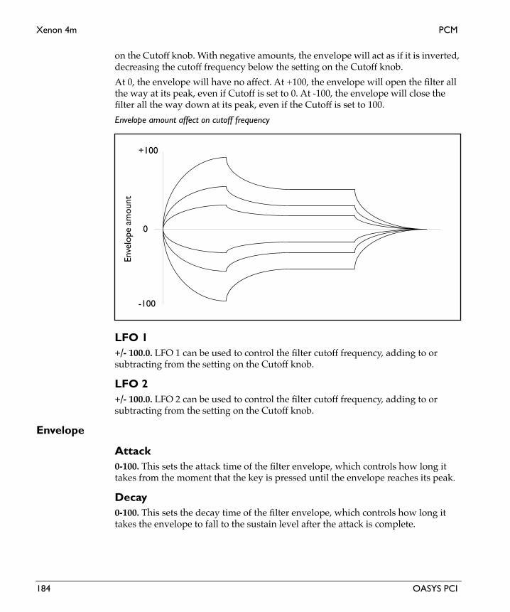
Xenon 4m PCM
Eng
lish
on the Cutoff knob. With negative amounts, the envelope will act as if it is inverted, decreasing the cutoff frequency below the setting on the Cutoff knob.
At 0, the envelope will have no affect. At +100, the envelope will open the filter all the way at its peak, even if Cutoff is set to 0. At -100, the envelope will close the filter all the way down at its peak, even if the Cutoff is set to 100.
Envelope amount affect on cutoff frequency
LFO 1+/- 100.0. LFO 1 can be used to control the filter cutoff frequency, adding to or subtracting from the setting on the Cutoff knob.
LFO 2+/- 100.0. LFO 2 can be used to control the filter cutoff frequency, adding to or subtracting from the setting on the Cutoff knob.
Envelope
Attack0-100. This sets the attack time of the filter envelope, which controls how long it takes from the moment that the key is pressed until the envelope reaches its peak.
Decay 0-100. This sets the decay time of the filter envelope, which controls how long it takes the envelope to fall to the sustain level after the attack is complete.
+100
-100
0
Enve
lope
am
ount
184 OASYS PCI

PCM Xenon 4m
Sustain0-100. This sets the sustain level for the filter envelope. After the decay time is complete, the envelope will stay at this level as long as the note is held.
Release0-100. This sets the release time of the filter envelope, which controls how long it takes the envelope to fall to zero after the note is released.
ADSR Envelope
Key Tracking
Amount+/- 100. This adjusts the filter cutoff as you play higher and lower on the keyboard. At the center key (as set below), the cutoff will be exactly the value set by the Cutoff knob. With positive tracking, the cutoff will increase as you play above the center key, and decrease as you play below it. With negative tracking, cutoff will decrease as you play above the center key, and increase as you play below it.
Note that you can also modulate any parameter using the “Key Tracking” modulators in the Mod Palette.
CenterC-1 to G#9. This sets the key around which the filter tracking is centered.
Amplifier
EnvelopeThese parameters control an ADSR envelope dedicated to the output volume. For a graphic explaining ADSR envelopes, see the figure “ADSR Envelope,” above.
Attack time Decay time Release timeSustain while
SustainLevel
holding note
Enve
lope
Am
ount
OASYS PCI 185

Xenon 4m PCM
Eng
lish
Attack0-100. This sets the attack time of the amplitude envelope, which controls how long it takes from the moment that the key is pressed until the envelope reaches its peak.
Decay 0-100. This sets the decay time of the amplitude envelope, which controls how long it takes the envelope to fall to the sustain level after the attack is complete.
Sustain0-100. This sets the sustain level for the amplitude envelope. After the decay time is complete, the envelope will stay at this level as long as the note is held.
Release0-100. This sets the release time of the amplitude envelope, which controls how long it takes the envelope to fall to zero after the note is released.
Amp Mod
LFO 10.0-100.0. This sets the amount by which LFO 1 modulates amplitude.
LFO 20.0-100.0. This sets the amount by which LFO 2 modulates amplitude.
Volume+12 to -123.9dB, -INF. This is the output volume for the Patch.
IMPORTANT: The output volume provides up to 12dB in gain, so that you can get your signals as hot as possible. However, if filter resonance is high, settings above 0dB may cause clipping.
This control has extra smoothing on the DSP, to ensure zipper-free modulation. If you want to modulate the volume instantaneously via velocity, use the Vel Sens control instead.
Vel Sens (Velocity Sensitivity)0-100. This sets the sensitivity of output volume to velocity. A velocity of 127 will always result in the maximum output level, as set by the Volume control; increasing the Vel Sens will decrease the output volume for low velocities.
186 OASYS PCI

PCM Xenon 4m
Global LFO 1
Waveform
WaveformTriangle, Sine, Saw Up, Saw Down, Square, Sample & Hold. This selects the waveform of the LFO.
LFO Waveforms and Phase
Shape+/-100. This adjusts the shape of the LFO waveform, from logarithmic to linear to exponential. Positive values shape the waveform so that it spends more time in the “up” part of the cycle, and negative values make it spend more time in the “down” part of the cycle, as shown below.
0˚ 90˚ 180˚-90˚-180˚
0˚ 90˚ 180˚-90˚-180˚
+/-180˚-90˚ 0˚90˚0˚ 0˚ 90˚ 180˚-90˚-180˚
0˚ 90˚ 180˚-90˚-180˚+/-180˚-90˚ 0˚90˚0˚
Triangle
Sine Saw Down
Saw Up
Sample & Hold
Square
OASYS PCI 187

Xenon 4m PCM
Eng
lish
LFO Shape
Offset+/-100. This offsets the center point of the LFO, allowing you to create modulation which is only positive or only negative, or anywhere in between. 0 is the default.
LFO ControlFrequency Knob, Manual Tempo, MIDI Tempo. The LFO speed can be controlled either by the Frequency knob (including the mod source), the Manual Tempo knob, or by MIDI Tempo (derived from MIDI clocks).
If this is set to Frequency Knob, then the LFO speed will be controlled by the settings in the Frequency section, including the mod source and amount.
If this is set to Manual Tempo, then the Manual Tempo knob will set the basic tempo, and the note value set in the Subdivisions menu will control the LFO speed.
If this is set to MIDI Tempo, then incoming MIDI Clocks will set the basic tempo, and the note value set in the Subdivisions menu will control the LFO speed.
Phase
Initial PhaseThis sets the point in the waveform at which the LFO starts. Whenever the Phase Reset controller is received, the LFO will start from the Initial Phase point.
Phase ResetList of Modulation Sources. This sets the MIDI controller which will reset the LFO’s phase to the Initial Phase point. You can use this to trigger the LFO from a MIDI sequencer, so that it always starts at the same point. This is especially useful in conjunction with MIDI Tempo synchronization. For a complete list of mod sources, please see “Modulation Sources” on page 2.
LFO Shape = 0 to +100 LFO Shape = 0 to -100
Sine Waveform
188 OASYS PCI
PCM Xenon 4m
To make sure that the LFO’s phase is correct when working with a sequencer, it’s best to include the phase reset controller every few bars in the sequence, so that no matter where you start playback, the LFO will be reset appropriately.
FrequencyThe controls in the Frequency section only apply when the LFO Control is set to Frequency Knob.
Frequency0.00-20.00Hz. This controls the speed of the LFO when the LFO Control is set to Frequency Knob.
Frequency ModList of Modulation Sources. This sets the modulation source for controlling the LFO speed. For a complete list, please see “Modulation Sources” on page 2.
Amount+/-20.00Hz. This sets the amount by which the mod source affects the LFO speed.
Fade-In0-100. The LFO can be at full level instantly, or can fade in over time after a note is played. This parameter controls how long it takes the LFO to rise to full level after the first note is pressed.
When you release all notes on the keyboard, and then play a new note, the LFO fade-in will start again.
Tempo
Manual Tempo40-240 bpm. This sets the tempo when the LFO Control is set to Manual Tempo.
Subdivision1/32, 1/32 dotted, 1/16, 1/16 dotted, 1/16 triplet, 1/8, 1/8 dotted, 1/8 triplet, 1/4, 1/4 dotted, 1/4 triplet, 1/2, 1/2 dotted, 1/2 triplet, 1 whole note, 2 whole notes. This sets the note value of a single LFO waveform cycle when the LFO Control is set to either Manual Tempo or MIDI Tempo.
Global LFO 2The parameters for Global LFO 2 are the same as those for Global LFO 1, as described above.
OASYS PCI 189

Percussion
Eng
lish
Percussion
190 OASYS PCI

Percussion Percussion Synth
Percussion SynthThis Patch is an analog-style percussion synthesizer, very similar to the synth voices in the Korg Electribe-R. It includes an oscillator, a noise generator, a pitch/modulation envelope, and an amplitude envelope.
Oscillator
WaveformTriangle, Sine. This selects the waveform for the oscillator.
Pitch+/-48.0. This sets the tuning of the oscillator, in semitones.
Phase+/-100. This is the initial phase of the oscillator when triggered by the Phase Reset controller, as set below. Extreme values (+/-100) will cause an extra click when the phase is reset, which can be good for enhancing the attack transient.
Phase ResetList of Modulation Sources. This sets the modulation source for controlling the phase reset. For a complete list, please see “Modulation Sources” on page 2.
The oscillator is free-running, and does not necessarily reset its phase every time that the sound is triggered. By setting the Phase Reset to Note Gate, you can make the phase retrigger on note-on.
If you like, you can also set Phase Reset to None. This will cause the phase to be essentially random on note-on, so that each note sounds a little different.
Pitch Modulation
TypeSaw, Square, Triangle, Random, Noise EG, Envelope. This selects the way in which the pitch is modulated.
Saw, Square, Triangle. The pitch will be modulated by an LFO, with the specified waveform. The speed and depth of the LFO are set by the Speed and Depth parameters, below.
Random. The pitch will be modulated by a sample-and-hold LFO, with speed and depth as set below. The sample-and-hold mechanism uses the main noise generator, so that the Noise Color parameters will affect the LFO as well. The Random setting gives especially interesting results with high Speed settings.
Noise EG. This adds noise to the output; you can control the timbre of the noise using the controls under Noise Color, below. The noise has a dedicated envelope,
OASYS PCI 191

Percussion Synth Percussion
Eng
lish
whose decay time is controlled by the Speed knob. The Depth knob controls the level of the noise. The pitch of the oscillator will not be modulated.
Envelope. The oscillator pitch will be modulated by a simple envelope, whose decay time is controlled by the Speed knob. The Depth knob controls the amount of pitch modulation. When using negative Depth settings, you may need to set the oscillator Pitch fairly high.
Speed0.0-100.0. The Speed control changes in meaning according to the Type selection. With Saw, Square, Triangle, and Random, the Speed sets the frequency of the LFO. With Noise EQ and Envelope, the Speed sets the envelope decay time.
Depth0-100. The Depth control changes in meaning according to the Type selection. With Saw, Square, Triangle, Random, and Envelope, the Depth sets the amount of pitch modulation. With Noise EQ, the Depth sets the volume of the noise.
Noise ColorThis section controls the timbre of the noise when the Type is set to Noise EG. It also affects the sample-and-hold LFO when the Oscillator Pitch Mod Type is set to Random.
Cutoff0-100. This controls the cutoff frequency of a highpass filter dedicated to the noise generator.
Resonance0-100. This controls the resonance of the highpass filter.
Amplifier
Decay0-100. This sets the decay time of the amplitude envelope. Higher settings mean a longer decay time.
Bass Boost0-100. This increases the bass frequencies in the output signal.
Level0-100. This sets the overall volume level of the Patch.
192 OASYS PCI

Percussion Percussion Synth 2
Percussion Synth 2This Patch is an enhanced version of the Percussion Synth, adding independent control of oscillator and noise output levels, a selection of filter types for the noise generator, and a full ADSR amplitude envelope.
Oscillator
WaveformTriangle, Sine. This selects the waveform for the oscillator.
Pitch+/-48.0. This sets the tuning of the oscillator, in semitones.
Phase+/-100. This is the initial phase of the oscillator when triggered by the Phase Reset controller, as set below. Extreme values (+/-100) will cause an extra click when the phase is reset, which can be good for enhancing the attack transient.
Phase ResetList of Modulation Sources. This sets the modulation source for controlling the phase reset. For a complete list, please see “Modulation Sources” on page 2.
The oscillator is free-running, and does not necessarily reset its phase every time that the sound is triggered. By setting the Phase Reset to Note Gate, you can make the phase retrigger on note-on.
If you like, you can also set Phase Reset to None. This will cause the phase to be essentially random on note-on, so that each note sounds a little different.
Level0-100. This sets the volume level of the oscillator.
Pitch Modulation
TypeSaw, Square, Triangle, Random, Noise EG, Envelope. This selects the way in which the pitch is modulated.
Saw, Square, Triangle. The pitch will be modulated by an LFO, with the specified waveform. The speed and depth of the LFO are set by the Speed and Depth parameters, below.
Random. The pitch will be modulated by a sample-and-hold LFO, with speed and depth as set below. The sample-and-hold mechanism uses the main noise generator, so that the Noise Color parameters will affect the LFO as well. The Random setting gives especially interesting results with high Speed settings.
OASYS PCI 193

Percussion Synth 2 Percussion
Eng
lish
Noise EG. This adds noise to the output; you can control the timbre of the noise using the controls under Noise Color, below. The noise has a dedicated envelope, whose decay time is controlled by the Speed knob. The Depth knob controls the level of the noise. The pitch of the oscillator will not be modulated.
Envelope. The oscillator pitch will be modulated by a simple envelope, whose decay time is controlled by the Speed knob. The Depth knob controls the amount of pitch modulation. When using negative Depth settings, you may need to set the oscillator Pitch fairly high.
Speed0.0-100.0. The Speed control changes in meaning according to the Type selection. With Saw, Square, Triangle, and Random, the Speed sets the frequency of the LFO. With Noise EQ and Envelope, the Speed sets the envelope decay time.
Depth0-100. The Depth control changes in meaning according to the Type selection. With Saw, Square, Triangle, Random, and Envelope, the Depth sets the amount of pitch modulation. With Noise EQ, the Depth sets the amount of the noise added to the oscillator output (in addition to the level set under Noise, below).
NoiseThis section controls the timbre of the noise generator, and also affects the sample-and-hold LFO when the Oscillator Pitch Mod Type is set to Random. The filter settings do not affect the timbre of the oscillator.
FilterLowpass, Bandpass, Bandstop, Highpass. This controls the type of filter dedicated to the noise generator.
Cutoff0-100. This controls the cutoff frequency of the filter dedicated to the noise generator.
Resonance0-100. This controls the resonance of the filter.
Level0-100. This sets the volume level of the noise generator.
Amplifier
Attack0-100. This sets the attack time of the amplitude envelope, which controls how long it takes from the moment that the key is pressed until the envelope reaches its peak.
194 OASYS PCI

Percussion Percussion Synth 2
Decay 0-100. This sets the decay time of the amplitude envelope, which controls how long it takes the envelope to fall to the sustain level after the attack is complete.
Sustain0-100. This sets the sustain level for the amplitude envelope. After the decay time is complete, the envelope will stay at this level as long as the note is held.
Release0-100. This sets the release time of the amplitude envelope, which controls how long it takes the envelope to fall to zero after the note is released.
ADSR Envelope
Bass Boost0-100. This increases the bass frequencies in the output signal.
Level0-100. This sets the overall volume level of the Patch.
Attack time Decay time Release timeSustain while
SustainLevel
holding note
Enve
lope
Am
ount
OASYS PCI 195

Beat Box Percussion
Eng
lish
Beat BoxThis Patch combines two analog-style percussion synthesizers, similar to the Percussion Synth, with a MIDI-synced sequencer.
To trigger the Beat Box from MIDI, set Sequence Start/Stop to Stop, and then modulate this parameter with Note Gate. For best results, re-trigger the Beat Box every few measures.
Percussion 1 and 2The two percussion synth voices are identical to each other. They are very similar to the Percussion synth, except that the initial phase and phase reset are preset.
WaveformTriangle, Sine. This selects the waveform for the oscillator.
Pitch0-100. This sets the tuning of the oscillator.
Pitch Modulation
TypeSaw, Square, Triangle, Random, Noise EG, Envelope. This selects the way in which the pitch is modulated.
Saw, Square, Triangle. The pitch will be modulated by an LFO, with the specified waveform. The speed and depth of the LFO are set by the Speed and Depth parameters, below.
Random. The pitch will be modulated by a sample-and-hold LFO, with speed and depth as set below. The sample-and-hold mechanism uses the main noise generator, so that the Noise Color parameters will affect the LFO as well. The Random setting gives especially interesting results with high Speed settings.
Noise EG. This adds noise to the output; you can control the timbre of the noise using the controls under Noise Color, below. The noise has a dedicated envelope, whose decay time is controlled by the Speed knob. The Depth knob controls the level of the noise. The pitch of the oscillator will not be modulated.
Envelope. The oscillator pitch will be modulated by a simple envelope, whose decay time is controlled by the Speed knob. The Depth knob controls the amount of pitch modulation. When using negative Depth settings, you may need to set the oscillator Pitch fairly high.
Speed0.0-100.0. The Speed control changes in meaning according to the Type selection. With Saw, Square, Triangle, and Random, the Speed sets the frequency of the LFO. With Noise EQ and Envelope, the Speed sets the envelope decay time.
196 OASYS PCI

Percussion Beat Box
Depth0-100. The Depth control changes in meaning according to the Type selection. With Saw, Square, Triangle, Random, and Envelope, the Depth sets the amount of pitch modulation. With Noise EQ, the Depth sets the volume of the noise.
Noise ColorThis section controls the timbre of the noise when the Type is set to Noise EG. It also affects the sample-and-hold LFO when the Oscillator Pitch Mod Type is set to Random.
Cutoff0-100. This controls the cutoff frequency of a highpass filter dedicated to the noise generator.
Resonance0-100. This controls the resonance of the highpass filter.
Amplifier
Decay0-100. This sets the decay time of the amplitude envelope. Higher settings mean a longer decay time.
Bass Boost0-100. This increases the bass frequencies in the output signal.
Level0-100. This sets the overall volume level of the synth.
Trigger 1 (switches 1-16)On, Off. These sixteen switches control the step sequencer for Percussion Synth 1. Each switch represents one sixteenth note. If the switch is on, the synth will be triggered on that step; if it is off, the synth will not be triggered.
Trigger 2 (switches 1-16)On, Off. These sixteen switches control the step sequencer for Percussion Synth 2. Each switch represents one sixteenth note. If the switch is on, the synth will be triggered on that step; if it is off, the synth will not be triggered.
Accent (switches 1-16)On, Off. These sixteen switches control the step sequencer’s accent function. Each switch represents one sixteenth note. Accent increases the synths’ output levels for the given step. If the switch is on, synths triggered on that step will be accented; if it is off, synths will not be accented.
OASYS PCI 197

Beat Box Percussion
Eng
lish
Step Sequencer
SequenceStop, Run. This controls whether the sequencer is running or stopped. To trigger the Beat Box via MIDI, set this to Stop, and then modulate with Note Gate.
ClockManual Tempo, MIDI Tempo. This sets whether the sequencer will use the tempo set by the Manual Tempo knob, or tempo received via MIDI.
Manual Tempo40-240 bpm. This sets the tempo, in beats per minute, when the Clock is set to Manual Tempo. If the Clock is set to MIDI Tempo, this knob is ignored.
Loop Start1-16. The sequence will always start at step 1, but when it begins to repeat, it will jump to the step specified here. You can modulate this via MIDI, to create fluctuating patterns.
Loop End1-16. This sets the end step for the sequence. When the sequence completes this step, it will return to the Loop Start.
198 OASYS PCI

VPM
VPM
OASYS PCI 199

VPM 2 OP VPM
Eng
lish
VPM 2 OPThis Patch is a two-operator VPM synthesizer. VPM stands for Virtual Phase Modulation, in which the phase of one oscillator (the Carrier) is modulated by another oscillator (the Modulator), producing a complex timbre. The combination of an oscillator and its amplitude envelope is known as an “operator.” VPM is particularly well-suited to bells and electric pianos, although it can produce many other sounds as well.
VPM 2 OP
Carrier - OP 1
OscillatorThe carrier operator determines the basic pitch and amplitude envelope. The modulator operator changes the timbre of this oscillator.
Ratio1.0-31.0. This selects the basic tuning for the oscillator.
Fine0.0-100.0. This allows you to fine-tune the ratio. You can think of this as the digits to the right of the decimal. For instance, setting the Ratio to 3.0 and Fine to 53.0 results in an actual ratio of 3.53. Setting Fine to 100 is the same as increasing the Ratio by 1.
Detune+/-10.00. This allows you to detune the oscillator, in cents (1/100 of a semitone).
WaveformSine, Sine + 1st Harmonic, Sine + 1st & 2nd Harm. This sets the waveform for the oscillator.
EnvelopeThis envelope controls the overall output level of the Patch.
OP 2
OP 1 Audio output
VPM modulation
200 OASYS PCI

VPM VPM 2 OP
Attack0-100. This sets the attack time of the amplitude envelope, which controls how long it takes from the moment that the key is pressed until the envelope reaches its peak.
Decay 0-100. This sets the decay time of the amplitude envelope, which controls how long it takes the envelope to fall to the sustain level after the attack is complete.
Sustain0-100. This sets the sustain level for the amplitude envelope. After the decay time is complete, the envelope will stay at this level as long as the note is held.
Release0-100. This sets the release time of the amplitude envelope, which controls how long it takes the envelope to fall to zero after the note is released.
ADSR Envelope
Level0.0-100.0. This is the output volume for the operator, and for the Patch as a whole.
The level knob has extra smoothing on the DSP, to ensure zipper-free modulation. If you want to modulate the volume instantaneously via velocity, use the Vel Sens control instead.
Vel Sens (Velocity Sensitivity)0-100. This sets the sensitivity of output volume to velocity. A velocity of 127 will always result in the maximum output level, as set by the Volume control; increasing the Vel Sens will decrease the output volume for low velocities.
Modulator - OP 2
OscillatorThe modulator operator changes the timbre of the carrier operator.
Attack time Decay time Release timeSustain while
SustainLevel
holding note
Enve
lope
Am
ount
OASYS PCI 201
VPM 2 OP VPM
Eng
lish
Ratio1.0-31.0. This selects the basic tuning for the oscillator. Changing the modulator’s ratio will affect the timbre of the carrier.
Fine0.0-100.0. This allows you to fine-tune the ratio. You can think of this as the digits to the right of the decimal. For instance, setting the Ratio to 3.0 and Fine to 53.0 results in an actual ratio of 3.53. Setting Fine to 100 is the same as increasing the Ratio by 1.
Settings other than 0.0 can cause dramatic differences in the timbre of the carrier.
Detune+/-10.00. This allows you to detune the oscillator, in cents (1/100 of a semitone). Settings other than 0.0 can cause dramatic differences in the timbre of the carrier.
WaveformSine, Sine + 1st Harmonic, Sine + 1st & 2nd Harm. This sets the waveform for the oscillator. Changing the modulator’s waveform will affect the timbre of the carrier.
Feedback+/-100. Feedback allows the operator to self-modulate, which changes the shape of the waveform. At high levels of feedback, the waveform will approach a sawtooth shape.
EnvelopeThis envelope allows you to change the level of the modulator over time, which in turn changes the timbre of the carrier. This affect is conceptually similar to the filter envelope in an analog synth, although the actual change in timbre can be quite different.
Attack0-100. This sets the attack time of the amplitude envelope, which controls how long it takes from the moment that the key is pressed until the envelope reaches its peak.
Decay 0-100. This sets the decay time of the amplitude envelope, which controls how long it takes the envelope to fall to the sustain level after the attack is complete.
Sustain0-100. This sets the sustain level for the amplitude envelope. After the decay time is complete, the envelope will stay at this level as long as the note is held.
Release0-100. This sets the release time of the amplitude envelope, which controls how long it takes the envelope to fall to zero after the note is released.
Level0.0-100.0. This is the output volume for the operator, which controls the overall amount of modulation to the carrier.
202 OASYS PCI

VPM VPM 2 OP
The level knob has extra smoothing on the DSP, to ensure zipper-free modulation. If you want to modulate the volume instantaneously via velocity, use the Vel Sens control instead.
Vel Sens (Velocity Sensitivity)0-100. This sets the sensitivity of output volume to velocity. A velocity of 127 will always result in the maximum output level, as set by the Volume control; increasing the Vel Sens will decrease the output volume for low velocities.
Vibrato
Frequency0.0-20.0 Hz. This controls the initial speed of the vibrato.
Frequency ModList of Modulation Sources. This sets the modulation source for controlling the vibrato frequency. For a complete list, please see “Modulation Sources” on page 2.
Amount0.0-10.0Hz. This sets the amount, in Hz, by which the mod source affects the vibrato frequency. When the mod source is at its maximum value, it will add this amount to the setting on the Frequency knob.
Depth0-100. This controls the initial depth of the vibrato–the amount of pitch modulation.
Depth ModList of Modulation Sources. This sets the modulation source for controlling the vibrato depth. For a complete list, please see “Modulation Sources” on page 2.
Amount0-100. This sets the amount by which the mod source affects the vibrato depth.
OASYS PCI 203

VPM 4 OP VPM
Eng
lish
VPM 4 OPThis Patch is a four-operator VPM synthesizer, with two carrier-modulator pairs. The two pairs can be used to create layered sounds, with each contributing a different sonic element. This Patch is slightly more DSP-efficient than the more flexible VPM 4 OP Select.
VPM 4 OP
VPM stands for Virtual Phase Modulation, in which the phase of one oscillator (the Carrier) is modulated by another oscillator (the Modulator), producing a complex timbre. The combination of an oscillator and its amplitude envelope is known as an “operator.” VPM is particularly well-suited to bells and electric pianos, although it can produce many other sounds as well.
Carrier - OP 1 and OP 3
OscillatorThe carrier operators determine the basic pitches and amplitude envelopes, while the modulator operators change the timbre of the carriers. Modulator OP 2 controls the timbre of Carrier OP 1, and Modulator OP 4 controls the timbre of Carrier OP 3.
Ratio1.0-31.0. This selects the basic tuning for the oscillator.
Fine0.0-100.0. This allows you to fine-tune the ratio. You can think of this as the digits to the right of the decimal. For instance, setting the Ratio to 3.0 and Fine to 53.0 results in an actual ratio of 3.53. Setting Fine to 100 is the same as increasing the Ratio by 1.
OP 1 OP 3
Audio output
VPM modulationVPM modulation
OP 4
Feedback
OP 2
Feedback
204 OASYS PCI

VPM VPM 4 OP
Detune+/-10.00. This allows you to detune the oscillator, in cents (1/100 of a semitone).
WaveformSine, Sine + 1st Harmonic, Sine + 1st & 2nd Harm. This sets the waveform for the oscillator.
EnvelopeThis envelope controls the overall output level of the Patch.
Attack0-100. This sets the attack time of the amplitude envelope, which controls how long it takes from the moment that the key is pressed until the envelope reaches its peak.
Decay 0-100. This sets the decay time of the amplitude envelope, which controls how long it takes the envelope to fall to the sustain level after the attack is complete.
Sustain0-100. This sets the sustain level for the amplitude envelope. After the decay time is complete, the envelope will stay at this level as long as the note is held.
Release0-100. This sets the release time of the amplitude envelope, which controls how long it takes the envelope to fall to zero after the note is released.
ADSR Envelope
Level0.0-100.0. This is the output volume for the operator.
The level knob has extra smoothing on the DSP, to ensure zipper-free modulation. If you want to modulate the volume instantaneously via velocity, use the Vel Sens control instead.
Attack time Decay time Release timeSustain while
SustainLevel
holding note
Enve
lope
Am
ount
OASYS PCI 205

VPM 4 OP VPM
Eng
lish
Vel Sens (Velocity Sensitivity)0-100. This sets the sensitivity of output volume to velocity. A velocity of 127 will always result in the maximum output level, as set by the Volume control; increasing the Vel Sens will decrease the output volume for low velocities.
Modulator - OP 2 and OP 4
OscillatorThe modulator operators change the timbre of the carriers. Modulator OP 2 controls the timbre of Carrier OP 1, and Modulator OP 4 controls the timbre of Carrier OP 3.
Ratio1.0-31.0. This selects the basic tuning for the oscillator. Changing the modulator’s ratio will affect the timbre of the carrier.
Fine0.0-100.0. This allows you to fine-tune the ratio. You can think of this as the digits to the right of the decimal. For instance, setting the Ratio to 3.0 and Fine to 53.0 results in an actual ratio of 3.53. Setting Fine to 100 is the same as increasing the Ratio by 1.
Settings other than 0.0 can cause dramatic differences in the timbre of the carrier.
Detune+/-10.00. This allows you to detune the oscillator, in cents (1/100 of a semitone). Settings other than 0.0 can cause dramatic differences in the timbre of the carrier.
WaveformSine, Sine + 1st Harmonic, Sine + 1st & 2nd Harm. This sets the waveform for the oscillator. Changing the modulator’s waveform will affect the timbre of the carrier.
Feedback+/-100. Feedback allows the operator to self-modulate, which changes the shape of the waveform. At high levels of feedback, the waveform will approach a sawtooth shape.
EnvelopeThis envelope allows you to change the level of the modulator over time, which in turn changes the timbre of the carrier. This affect is conceptually similar to the filter envelope in an analog synth, although the actual change in timbre can be quite different.
Attack0-100. This sets the attack time of the amplitude envelope, which controls how long it takes from the moment that the key is pressed until the envelope reaches its peak.
206 OASYS PCI

VPM VPM 4 OP
Decay 0-100. This sets the decay time of the amplitude envelope, which controls how long it takes the envelope to fall to the sustain level after the attack is complete.
Sustain0-100. This sets the sustain level for the amplitude envelope. After the decay time is complete, the envelope will stay at this level as long as the note is held.
Release0-100. This sets the release time of the amplitude envelope, which controls how long it takes the envelope to fall to zero after the note is released.
Level0.0-100.0. This is the output volume for the operator, which controls the overall amount of modulation to the carrier.
The level knob has extra smoothing on the DSP, to ensure zipper-free modulation. If you want to modulate the volume instantaneously via velocity, use the Vel Sens control instead.
Vel Sens (Velocity Sensitivity)0-100. This sets the sensitivity of output volume to velocity. A velocity of 127 will always result in the maximum output level, as set by the Volume control; increasing the Vel Sens will decrease the output volume for low velocities.
Vibrato
Frequency0.0-20.0 Hz. This controls the initial speed of the vibrato.
Frequency ModList of Modulation Sources. This sets the modulation source for controlling the vibrato frequency. For a complete list, please see “Modulation Sources” on page 2.
Amount0.0-10.0Hz. This sets the amount, in Hz, by which the mod source affects the vibrato frequency. When the mod source is at its maximum value, it will add this amount to the setting on the Frequency knob.
Depth0-100. This controls the initial depth of the vibrato–the amount of pitch modulation.
Depth ModList of Modulation Sources. This sets the modulation source for controlling the vibrato depth. For a complete list, please see “Modulation Sources” on page 2.
OASYS PCI 207

VPM 4 OP VPM
Eng
lish
Amount0-100. This sets the amount by which the mod source affects the vibrato depth.
208 OASYS PCI

VPM VPM 4 OP Select
VPM 4 OP SelectThis Patch is a four-operator VPM synthesizer with eight selectable algorithms, as shown in “VPM 4 OP Select algorithms,” on page 212.
VPM stands for Virtual Phase Modulation, in which the phase of one oscillator (the Carrier) is modulated by another oscillator (the Modulator), producing a complex timbre. The combination of an oscillator and its amplitude envelope is known as an “operator.” VPM is particularly well-suited to bells and electric pianos, although it can produce many other sounds as well.
OP 1, OP 2, OP 3, OP 4The function of each operator will change depending on which algorithm is selected. In some algorithms, the operator may be a modulator; in others, it may be a carrier.
Carrier operators determine the basic pitch and amplitude envelope, while modulator operators change the timbre of the carriers.
Oscillator
Ratio1.0-31.0. This selects the basic tuning for the oscillator.
Fine0.0-100.0. This allows you to fine-tune the ratio. You can think of this as the digits to the right of the decimal. For instance, setting the Ratio to 3.0 and Fine to 53.0 results in an actual ratio of 3.53. Setting Fine to 100 is the same as increasing the Ratio by 1.
Detune+/-10.00. This allows you to detune the oscillator, in cents (1/100 of a semitone).
WaveformSine, Sine + 1st Harmonic, Sine + 1st & 2nd Harm. This sets the waveform for the oscillator.
Feedback (OP 4 Only)+/-100. Feedback allows the operator to self-modulate, which changes the shape of the waveform. At high levels of feedback, the waveform will approach a sawtooth shape.
EnvelopeThis envelope controls the output level of the operator.
Attack0-100. This sets the attack time of the amplitude envelope, which controls how long it takes from the moment that the key is pressed until the envelope reaches its peak.
OASYS PCI 209

VPM 4 OP Select VPM
Eng
lish
Decay 0-100. This sets the decay time of the amplitude envelope, which controls how long it takes the envelope to fall to the sustain level after the attack is complete.
Sustain0-100. This sets the sustain level for the amplitude envelope. After the decay time is complete, the envelope will stay at this level as long as the note is held.
Release0-100. This sets the release time of the amplitude envelope, which controls how long it takes the envelope to fall to zero after the note is released.
ADSR Envelope
Level0.0-100.0. This is the output level for the operator. If the operator is a modulator, it will control the volume; if it is a carrier, it will control the amount of modulation.
The level knob has extra smoothing on the DSP, to ensure zipper-free modulation. If you want to modulate the volume instantaneously via velocity, use the Vel Sens control instead.
Vel Sens (Velocity Sensitivity)0-100. This sets the sensitivity of output volume to velocity. A velocity of 127 will always result in the maximum output level, as set by the Volume control; increasing the Vel Sens will decrease the output volume for low velocities.
Attack time Decay time Release timeSustain while
SustainLevel
holding note
Enve
lope
Am
ount
210 OASYS PCI

VPM VPM 4 OP Select
Vibrato
Frequency0.0-20.0 Hz. This controls the initial speed of the vibrato.
Frequency ModList of Modulation Sources. This sets the modulation source for controlling the vibrato frequency. For a complete list, please see “Modulation Sources” on page 2.
Amount0.0-10.0Hz. This sets the amount, in Hz, by which the mod source affects the vibrato frequency. When the mod source is at its maximum value, it will add this amount to the setting on the Frequency knob.
Depth0-100. This controls the initial depth of the vibrato–the amount of pitch modulation.
Depth ModList of Modulation Sources. This sets the modulation source for controlling the vibrato depth. For a complete list, please see “Modulation Sources” on page 2.
Amount0-100. This sets the amount by which the mod source affects the vibrato depth.
OASYS PCI 211

VPM 4 OP Select VPM
Eng
lish
Algorithm SelectAlg 1-8. The algorithm controls which operators are carriers, which are modulators, and how all of the operators are connected together. There are eight different algorithms, as shown below.
VPM 4 OP Select algorithms
OP 2
OP 1
OP 3
Out
VPM
VPM
VPM
Alg 1
OP 2
OP 1
OP 3OP 4
Out
VPM
VPM
Fdbk
Alg 2
VPM
OP 4
Fdbk
OP 3
OP 1
OP 2OP 4
Out
VPM
VPM
Fdbk
Alg 3
VPM
OP 1
OP 3OP 2
Out
VPM
VPM
Alg 4
VPM
OP 4
Fdbk
OP 4
Out
Fdbk
Alg 6
VPM
OP 1 OP3OP 2
OP 4
Out
Fdbk
VPM
OP 1 OP3OP 2
Alg 7
OP 4
Out
Fdbk
OP 1 OP3OP 2
Alg 8
OP 2
OP 1
VPM
OP 3
VPM
OP 4
Fdbk
OutAlg 5
212 OASYS PCI

VPM VPM 4 OP Stack
VPM 4 OP StackThis Patch is a four-operator VPM synthesizer, with one carrier and three modulators. The three modulators control each other in series, and then the result controls the timbre of the carrier. This Patch is slightly more DSP-efficient than the more flexible VPM 4 OP Select.
VPM 4 OP Stack
VPM stands for Virtual Phase Modulation, in which the phase of one oscillator (the Carrier) is modulated by another oscillator (the Modulator), producing a complex timbre. The combination of an oscillator and its amplitude envelope is known as an “operator.” VPM is particularly well-suited to bells and electric pianos, although it can produce many other sounds as well.
Carrier - OP 1
OscillatorThe carrier operator determines the basic pitch and amplitude envelope, while the modulator operators change the timbre of the carrier.
Ratio1.0-31.0. This selects the basic tuning for the oscillator.
OP 2
OP 1
OP 3
OP 4
Audio output
VPM modulation
VPM modulation
VPM modulation
Feedback
OASYS PCI 213

VPM 4 OP Stack VPM
Eng
lish
Fine0.0-100.0. This allows you to fine-tune the ratio. You can think of this as the digits to the right of the decimal. For instance, setting the Ratio to 3.0 and Fine to 53.0 results in an actual ratio of 3.53. Setting Fine to 100 is the same as increasing the Ratio by 1.
Detune+/-10.00. This allows you to detune the oscillator, in cents (1/100 of a semitone).
WaveformSine, Sine + 1st Harmonic, Sine + 1st & 2nd Harm. This sets the waveform for the oscillator.
EnvelopeThis envelope controls the overall output level of the Patch.
Attack0-100. This sets the attack time of the amplitude envelope, which controls how long it takes from the moment that the key is pressed until the envelope reaches its peak.
Decay 0-100. This sets the decay time of the amplitude envelope, which controls how long it takes the envelope to fall to the sustain level after the attack is complete.
Sustain0-100. This sets the sustain level for the amplitude envelope. After the decay time is complete, the envelope will stay at this level as long as the note is held.
Release0-100. This sets the release time of the amplitude envelope, which controls how long it takes the envelope to fall to zero after the note is released.
ADSR Envelope
Attack time Decay time Release timeSustain while
SustainLevel
holding note
Enve
lope
Am
ount
214 OASYS PCI

VPM VPM 4 OP Stack
Level0.0-100.0. This is the output volume for the operator, and for the Patch as a whole.
The level knob has extra smoothing on the DSP, to ensure zipper-free modulation. If you want to modulate the volume instantaneously via velocity, use the Vel Sens control instead.
Vel Sens (Velocity Sensitivity)0-100. This sets the sensitivity of output volume to velocity. A velocity of 127 will always result in the maximum output level, as set by the Volume control; increasing the Vel Sens will decrease the output volume for low velocities.
Modulators - OP 2, OP 3, and OP 4The modulators in this Patch act in series, so that OP 4 controls OP 3, OP 3 controls OP 2, and the resulting complex waveform controls the timbre of OP 1, the carrier.
Oscillator
Ratio1.0-31.0. This selects the basic tuning for the oscillator. Changing the modulator’s ratio will affect the timbre of the carrier.
Fine0.0-100.0. This allows you to fine-tune the ratio. You can think of this as the digits to the right of the decimal. For instance, setting the Ratio to 3.0 and Fine to 53.0 results in an actual ratio of 3.53. Setting Fine to 100 is the same as increasing the Ratio by 1.
Settings other than 0.0 can cause dramatic differences in the timbre of the carrier.
Detune+/-10.00. This allows you to detune the oscillator, in cents (1/100 of a semitone). Settings other than 0.0 can cause dramatic differences in the timbre of the carrier.
WaveformSine, Sine + 1st Harmonic, Sine + 1st & 2nd Harm. This sets the waveform for the oscillator. Changing the modulator’s waveform will affect the timbre of the carrier.
Feedback (OP 4 Only)+/-100. Feedback allows the operator to self-modulate, which changes the shape of the waveform. At high levels of feedback, the waveform will approach a sawtooth shape.
EnvelopeThis envelope allows you to change the level of the modulator over time, which in turn changes the timbre of the carrier. This affect is conceptually similar to the filter envelope in an analog synth, although the actual change in timbre can be quite different.
OASYS PCI 215

VPM 4 OP Stack VPM
Eng
lish
Attack0-100. This sets the attack time of the amplitude envelope, which controls how long it takes from the moment that the key is pressed until the envelope reaches its peak.
Decay 0-100. This sets the decay time of the amplitude envelope, which controls how long it takes the envelope to fall to the sustain level after the attack is complete.
Sustain0-100. This sets the sustain level for the amplitude envelope. After the decay time is complete, the envelope will stay at this level as long as the note is held.
Release0-100. This sets the release time of the amplitude envelope, which controls how long it takes the envelope to fall to zero after the note is released.
Level0.0-100.0. This is the output volume for the operator, which controls the overall amount of modulation to the carrier.
The level knob has extra smoothing on the DSP, to ensure zipper-free modulation. If you want to modulate the volume instantaneously via velocity, use the Vel Sens control instead.
Vel Sens (Velocity Sensitivity)0-100. This sets the sensitivity of output volume to velocity. A velocity of 127 will always result in the maximum output level, as set by the Volume control; increasing the Vel Sens will decrease the output volume for low velocities.
Vibrato
Frequency0.0-20.0 Hz. This controls the initial speed of the vibrato.
Frequency ModList of Modulation Sources. This sets the modulation source for controlling the vibrato frequency. For a complete list, please see “Modulation Sources” on page 2.
Amount0.0-10.0Hz. This sets the amount, in Hz, by which the mod source affects the vibrato frequency. When the mod source is at its maximum value, it will add this amount to the setting on the Frequency knob.
Depth0-100. This controls the initial depth of the vibrato–the amount of pitch modulation.
216 OASYS PCI

VPM VPM 4 OP Stack
Depth ModList of Modulation Sources. This sets the modulation source for controlling the vibrato depth. For a complete list, please see “Modulation Sources” on page 2.
Amount0-100. This sets the amount by which the mod source affects the vibrato depth.
OASYS PCI 217

Waveguide
Eng
lish
Waveguide
218 OASYS PCI
Waveguide Flute
FluteThis Patch is a physical model of a flute, including breath pressure, the tonal quality of the breath noise, the interaction between the breath and the bore, the tonal quality of the bore, playing style, and more.
Breath Pressure
Pressure0.0-100.0. This controls the overall force of the breath pressure, modeling how hard you are blowing into the flute.
Env Amount0.0-100.0 This sets the amount by which the envelope affects the breath input.
Attack0-100. This sets the attack time of the envelope, which controls how long it takes from the moment that the key is pressed until the envelope reaches its peak.
Decay 0-100. This sets the decay time of the envelope, which controls how long it takes the envelope to fall to the sustain level after the attack is complete.
Sustain0-100. This sets the sustain level for the envelope. After the decay time is complete, the envelope will stay at this level as long as the note is held.
Release0-100. This sets the release time of the envelope, which controls how long it takes the envelope to fall to zero after the note is released.
Breath Noise
Gain0.0-100.0. This is the maximum breath level, scaled by the Breath Pressure section’s Input and Input Mod parameters.
Frequency 0-8000Hz. The tone of the breath noise is shaped by a bandpass filter, and this controls the center frequency of that filter.
Width0.0-100.0. This controls the bandwidth of the filter. At 0, the filter will be very resonant.
OASYS PCI 219

Flute Waveguide
Eng
lish
ChiffThis is a simple envelope, modeling the initial attack of the flute. It can control both level (gain) and frequency (pitch).
Decay0-100. This controls the decay time of the chiff envelope.
Gain Amt0-100. This sets the amount by which the chiff envelope affects the flute’s volume level.
Freq Amt0-100. This sets the amount by which the chiff envelope affects the flute’s pitch.
Breath-Bore InteractionWhen a player blows into a flute mouthpiece, the breath of the player interacts with the air resonating within the flute. The player can control this by changing the opening of the lips, and by changing the angle of the flute. This section models that interaction, using a complex equation controlled by the parameters below. You can also think of the equation as a table, transforming input into output. It is difficult to describe the precise effects of the individual parameters on the sound; it’s best to just work with them and see what happens!
Offset+/-100.0. This is the offset for the equation.
Linear+/-100.0. This controls the linear amount.
Squared+/-100.0. This controls the squared amount.
Cubed+/-100.0. This controls the cubed amount.
Bore
Gain0.0-100.0. This is the maximum breath level, scaled by the Breath Pressure section’s Pressure and Pressure Mod parameters.
Reflection0.0-100.0. This is the degree of coupling between the mouthpiece and the bore, which controls how much the two parts of the instrument interact.
220 OASYS PCI

Waveguide Flute
Mode/Tune0.0-100.0. This models the distance from the mouth to the mouthpiece, which affects the pitch. Flautists will vary this distance to make small pitch corrections, by rolling the flute towards the mouth or away from it.
Small values will produce detuning; this range represents the practical distance that can be achieved by a real flautist. The model allows you to go further than you could in the real world, however, and after a certain point the pitch will jump by an octave into the next pitch mode. (Real-world flautists can create this mode jump by blowing very hard.)
Damping0-100. This controls the brightness of the bore.
Key Track0-100. This allows you to vary the damping according to the MIDI note.
Pitch ControllersYou can bend the pitch of the flute smoothly, or make it leap up and down by an octave in a “Mode Jump,” which real flautists can create by blowing very hard.
Pitch BendList of Modulation Sources. This sets the modulation source for creating a smooth pitch bend. For a complete list, please see “Modulation Sources” on page 2.
Mode JumpList of Modulation Sources. This sets the modulation source for controlling the mode jump. For a complete list, please see “Modulation Sources” on page 2.
LFOThe LFO allows you to modulate both pitch and breath pressure.
Frequency0.0-10.0 Hz. This controls the initial speed of the LFO.
Frequency ModList of Modulation Sources. This sets the modulation source for controlling the LFO frequency. For a complete list, please see “Modulation Sources” on page 2.
Amount0.0-10.0Hz. This sets the amount, in Hz, by which the mod source affects the LFO frequency. When the mod source is at its maximum value, it will add this amount to the setting on the Frequency knob.
OASYS PCI 221

Flute Waveguide
Eng
lish
LFO – > Pitch Depth
Depth0.0-100.0. This sets the initial depth of the LFO to pitch, before modulation.
Depth ModList of Modulation Sources. This sets the modulation source for controlling the LFO depth. For a complete list, please see “Modulation Sources” on page 2.
Mod Amt0.0-100.0. This sets the amount by which the mod source affects the pitch modulation depth.
LFO – > Breath Depth
Depth0.0-100.0. This sets the initial depth of the LFO to breath pressure, before modulation.
Depth ModList of Modulation Sources. This sets the modulation source for controlling the breath pressure depth. For a complete list, please see “Modulation Sources” on page 2.
Mod Amt0.0-100.0. This sets the amount by which the mod source affects the breath pressure modulation depth.
Output
Volume-INF, -69.63-0.00dB. This is the output volume for the flute. It has extra smoothing on the DSP, to ensure zipper-free modulation. If you want to modulate the volume instantaneously via velocity, use the Vel Sens control instead.
Vel Sens (Velocity Sensitivity)0-100. This sets the sensitivity of output volume to velocity. A velocity of 127 will always result in the maximum output level, as set by the Volume control; increasing the Vel Sens will decrease the output volume for low velocities.
Low Cut0-100. This sets the cutoff point of a low cut filter on the output of the flute. Higher settings will diminish the lower frequencies.
222 OASYS PCI

Waveguide Tenor Sax
Tenor SaxThis Patch is a physical model of a tenor saxophone, including breath pressure, the tonal quality of the breath noise, playing style, and the characteristics of the reed, bore, and bell.
Breath Pressure
Input0.0-100.0. This controls the overall force of the breath pressure, modeling how hard you are blowing into the sax.
Input ModList of Modulation Sources. This sets the modulation source for controlling the breath input. You might try using the mod wheel, or breath controller. For a complete list, please see “Modulation Sources” on page 2.
Amount0.0-100.0 This sets the amount by which the mod source affects the breath input.
Pressure0.0-100.0. This controls how much of the input goes to the reed, as opposed to the bore. If Pressure is set to 0, then the Reed and Growl sections will have little or no effect, as if you were blowing into an open tube. At higher pressures, the Reed and Growl will have more effect.
Pressure ModList of Modulation Sources. This sets the modulation source for controlling the breath pressure. For a complete list, please see “Modulation Sources” on page 2.
Amount0.0-100.0. This sets the amount by which the mod source affects the breath pressure.
Attack 0.0-100.0. This models the reed’s resistance to opening, or how hard it is to get the reed to start moving.
Release0.0-100.0. This models the reed’s resistance to closing.
OASYS PCI 223

Tenor Sax Waveguide
Eng
lish
Breath Noise
Gain0.0-100.0. This is the maximum breath level, scaled by the Breath Pressure section’s Input and Input Mod parameters.
Frequency 0-8000Hz. The tone of the breath noise is shaped by a bandpass filter, and this controls the center frequency of that filter.
Width0.0-100.0. This controls the bandwidth of the filter. At 0, the filter will be very resonant.
Reed
Onset0.00-100.00. Onset controls the gain through the mouthpiece.
Embouchure0.00-100.00. The embouchure is the way that the lips are pursed; it affects the tone of the reed.
Damping0.00-100.00. This controls the brightness of the reed.
Nonlinear0.00-100.00. The Nonlinear parameter adjusts the feedback within the reed; higher values make the reed more unstable.
Reflection+/-100.0. This is the degree of coupling between the reed and the bore, which controls how much the two parts of the instrument interact.
Growl
Instability0-100. This adds instability to the breath signal, modeling the breath and reed technique of the player.
Growl SourceList of Modulation Sources. This sets the modulation source for controlling the instability, or growl. For a complete list, please see “Modulation Sources” on page 2.
224 OASYS PCI

Waveguide Tenor Sax
Amount0-100. This sets the amount by which the mod source affects the growl.
Horn
Glide0-100. This models the time that the horn takes to transition between notes.
Bell Width0-5000Hz. This models the width of the saxophone’s bell, which acts as a highpass filter.
Bell Level0-100. This is the volume level from the saxophone’s bell, like putting a mic at the end of the horn.
Bore Level0-100. This is the volume level from within the saxophone’s bore, like putting a mic inside the sax. Mixing the bore with the bell allows additional control over the tone.
LFOThe LFO includes individual amounts to vibrato (for pitch modulation), bore (for brightness modulation), and breath pressure.
Frequency0.0-10.0 Hz. This controls the initial speed of the LFO.
Frequency ModList of Modulation Sources. This sets the modulation source for controlling the LFO frequency. For a complete list, please see “Modulation Sources” on page 2.
Amount0.0-10.0Hz. This sets the amount, in Hz, by which the mod source affects the LFO frequency. When the mod source is at its maximum value, it will add this amount to the setting on the Frequency knob.
Depth ControllerList of Modulation Sources. This sets the modulation source for controlling the LFO depth. For a complete list, please see “Modulation Sources” on page 2.
Vibrato Amount0.00-100.00. This sets the amount by which the mod source affects the pitch modulation depth.
OASYS PCI 225
Tenor Sax Waveguide
Eng
lish
Bore Amount0.00-100.00. This sets the amount by which the mod source affects the brightness of the bore.
Breath Amount0.00-100.00. This sets the amount by which the mod source affects the breath pressure.
Output
Lowpass0-24000 Hz. This sets the frequency of the overall lowpass filter. The filter can be used to make the sound more mellow and rounded.
226 OASYS PCI

Waveguide Trombone
TromboneThis Patch is a physical model of a trombone, including breath pressure, the character of the breath noise, the timbre of the bell, and authentic “rip” and vibrato effects.
Breath Pressure
Pressure0.0-100.0. This controls the overall force of the breath pressure, modeling how hard you are blowing into the trombone.
Pressure ModList of Modulation Sources. This sets the modulation source for controlling the breath input. You might try using the mod wheel, or breath controller. For a complete list, please see “Modulation Sources” on page 2.
Amount0.0-100.0 This sets the amount by which the mod source affects the breath pressure.
Envelope
Env Amount0.0-100.0 This sets the amount by which the envelope affects the breath pressure.
Attack0-100. This sets the attack time of the envelope, which controls how long it takes from the moment that the key is pressed until the envelope reaches its peak.
Decay0-100. This sets the decay time of the envelope, which controls how long it takes the envelope to fall to the sustain level after the attack is complete.
Sustain0-100. This sets the sustain level for the envelope. After the decay time is complete, the envelope will stay at this level as long as the note is held.
Release0-100. This sets the release time of the envelope, which controls how long it takes the envelope to fall to zero after the note is released.
Breath NoiseThis section controls the timbre and level of the breath noise; think of it as the sound that the player makes with their mouth, before entering the mouthpiece of
OASYS PCI 227
Trombone Waveguide
Eng
lish
the trombone. The timbre of the noise is controlled by a resonant bandpass filter, and there is a dedicated ramp envelope to control the level of the noise (for creating attack sounds).
Gain0.0-100.0. This is the maximum breath level, scaled by the Breath Pressure section’s Pressure and Pressure Mod parameters.
Frequency 0-24000Hz. The tone of the breath noise is shaped by a bandpass filter. This controls the center frequency of that filter.
Resonance0-100. This controls the resonance of the filter. At 0, the filter will not resonate at all; at 100, it will be very resonant.
Ramp Amt0-100. This sets the amount by which the ramp envelope (controlled by Ramp Decay, below) affects the volume level of the breath noise.
Ramp Decay0-100. This sets the decay time of the ramp envelope.
Output
Volume0.0-100.0. This is the output volume for the trombone. It has extra smoothing on the DSP, to ensure zipper-free modulation. If you want to modulate the volume instantaneously via velocity, use the Vel Sens control instead.
Vel Sens (Velocity Sensitivity)0-100. This sets the sensitivity of output volume to velocity. A velocity of 127 will always result in the maximum output level, as set by the Volume control; increasing the Vel Sens will decrease the output volume for low velocities.
BellThe bell affects the sound in two ways: by feeding back into the body of the instrument, and by shaping the timbre of the sound output. The highpass and lowpass filters, below, affect the output timbre.
Highpass0.00-100.00. This controls the cutoff frequency of the highpass filter. Frequencies below the cutoff will be attenuated, and frequencies above the cutoff will pass through unchanged.
228 OASYS PCI

Waveguide Trombone
You can use the highpass to create muted effects.
Resonance0.00-100.00. This controls the resonance of the highpass filter. Resonance emphasizes the frequencies around the cutoff frequency. At 0, there is no emphasis, and frequencies beyond the cutoff will simply diminish smoothly. At very high settings, the resonance can be heard as a separate, whistling pitch. At medium settings, the resonance will alter the timbre of the filter, but will not usually be heard as a separate pitch.
Lowpass0.00-100.00. This controls the cutoff frequency of the lowpass filter. Frequencies above the cutoff are attenuated, and frequencies below the cutoff are passed through unchanged.
Resonance0.00-100.00. This controls the resonance of the lowpass filter. Resonance emphasizes the frequencies around the cutoff frequency. At 0, there is no emphasis, and frequencies beyond the cutoff will simply diminish smoothly. At very high settings, the resonance can be heard as a separate, whistling pitch. At medium settings, the resonance will alter the timbre of the filter, but will not usually be heard as a separate pitch.
Pitch ControllersYou can bend the pitch of the trombone smoothly, as when moving the slide, or make it jump up and down in a “rip” which follows the harmonic series.
Octave RipList of Modulation Sources. This sets the modulation source for controlling the octave rip. For a complete list, please see “Modulation Sources” on page 2.
SlideList of Modulation Sources. This sets the modulation source for creating a smooth pitch bend, like moving the slide. For a complete list, please see “Modulation Sources” on page 2.
Vibrato Rate
Frequency0.00-10.00 Hz. This controls the initial speed of the LFO.
Frequency ModList of Modulation Sources. This sets the modulation source for controlling the LFO frequency. For a complete list, please see “Modulation Sources” on page 2.
OASYS PCI 229

Trombone Waveguide
Eng
lish
Amount0.0-10.0Hz. This sets the amount, in Hz, by which the mod source affects the LFO frequency. When the mod source is at its maximum value, it will add this amount to the setting on the Frequency knob.
Vibrato Depth
Depth0.00-100.00. This sets the initial depth of the vibrato LFO, before modulation.
Depth ModList of Modulation Sources. This sets the modulation source for controlling the vibrato depth. For a complete list, please see “Modulation Sources” on page 2.
Lip OnlyOn, Off. On brass instruments, you can achieve vibrato in two ways: by varying the embouchure of the lips, or by both varying the embouchure and moving the slide. For a standard trombone vibrato, turn Lip Only off; for an embouchure-only vibrato, turn Lip Only on.
Vibrato Amount0.00-100.00. This sets the amount by which the mod source affects the vibrato depth.
230 OASYS PCI

Waveguide Trumpet
TrumpetThis Patch is a physical model of a trumpet, including breath pressure, the character of the breath noise, the timbre of the bell, and authentic “rip” and vibrato effects.
Breath Pressure
Pressure0.0-100.0. This controls the overall force of the breath pressure, modeling how hard you are blowing into the trumpet.
Pressure ModList of Modulation Sources. This sets the modulation source for controlling the breath input. You might try using the mod wheel, or breath controller. For a complete list, please see “Modulation Sources” on page 2.
Amount0.0-100.0 This sets the amount by which the mod source affects the breath pressure.
Envelope
Env Amount0.0-100.0 This sets the amount by which the envelope affects the breath pressure.
Attack0-100. This sets the attack time of the envelope, which controls how long it takes from the moment that the key is pressed until the envelope reaches its peak.
Decay 0-100. This sets the decay time of the envelope, which controls how long it takes the envelope to fall to the sustain level after the attack is complete.
Sustain0-100. This sets the sustain level for the envelope. After the decay time is complete, the envelope will stay at this level as long as the note is held.
Release0-100. This sets the release time of the envelope, which controls how long it takes the envelope to fall to zero after the note is released.
Breath NoiseThis section controls the timbre and level of the breath noise; think of it as the sound that the player makes with their mouth, before entering the mouthpiece of
OASYS PCI 231

Trumpet Waveguide
Eng
lish
the trumpet. The timbre of the noise is controlled by a resonant bandpass filter, and there is a dedicated ramp envelope to control the level of the noise (for creating attack sounds).
Gain0.0-100.0. This is the maximum breath level, scaled by the Breath Pressure section’s Pressure and Pressure Mod parameters.
Frequency 0-24000Hz. The tone of the breath noise is shaped by a bandpass filter. This controls the center frequency of that filter.
Resonance0-100. This controls the resonance of the filter. At 0, the filter will not resonate at all; at 100, it will be very resonant.
Ramp Amt0-100. This sets the amount by which the ramp envelope (controlled by Ramp Decay, below) affects the volume level of the breath noise.
Ramp Decay0-100. This sets the decay time of the ramp envelope.
Output
Volume0.0-100.0. This is the output volume for the trumpet. It has extra smoothing on the DSP, to ensure zipper-free modulation. If you want to modulate the volume instantaneously via velocity, use the Vel Sens control instead.
Vel Sens (Velocity Sensitivity)0-100. This sets the sensitivity of output volume to velocity. A velocity of 127 will always result in the maximum output level, as set by the Volume control; increasing the Vel Sens will decrease the output volume for low velocities.
BellThe bell affects the sound in two ways: by feeding back into the body of the instrument, and by shaping the timbre of the sound output. The highpass and lowpass filters, below, affect the output timbre.
Highpass0.00-100.00. This controls the cutoff frequency of the highpass filter. Frequencies below the cutoff will be attenuated, and frequencies above the cutoff will pass through unchanged.
232 OASYS PCI

Waveguide Trumpet
You can use the highpass to create muted effects.
Resonance0.00-100.00. This controls the resonance of the highpass filter. Resonance emphasizes the frequencies around the cutoff frequency. At 0, there is no emphasis, and frequencies beyond the cutoff will simply diminish smoothly. At very high settings, the resonance can be heard as a separate, whistling pitch. At medium settings, the resonance will alter the timbre of the filter, but will not usually be heard as a separate pitch.
Lowpass0.00-100.00. This controls the cutoff frequency of the lowpass filter. Frequencies above the cutoff are attenuated, and frequencies below the cutoff are passed through unchanged.
Resonance0.00-100.00. This controls the resonance of the lowpass filter. Resonance emphasizes the frequencies around the cutoff frequency. At 0, there is no emphasis, and frequencies beyond the cutoff will simply diminish smoothly. At very high settings, the resonance can be heard as a separate, whistling pitch. At medium settings, the resonance will alter the timbre of the filter, but will not usually be heard as a separate pitch.
Pitch ControllersYou can bend the pitch of the trumpet smoothly, or make it jump up and down in a “rip” which follows the harmonic series.
Octave RipList of Modulation Sources. This sets the modulation source for controlling the octave rip. For a complete list, please see “Modulation Sources” on page 2.
SlideList of Modulation Sources. This sets the modulation source for creating a smooth pitch bend, like a slide trumpet. For a complete list, please see “Modulation Sources” on page 2.
Vibrato Rate
Frequency0.00-10.00 Hz. This controls the initial speed of the LFO.
Frequency ModList of Modulation Sources. This sets the modulation source for controlling the LFO frequency. For a complete list, please see “Modulation Sources” on page 2.
OASYS PCI 233

Trumpet Waveguide
Eng
lish
Amount0.0-10.0Hz. This sets the amount, in Hz, by which the mod source affects the LFO frequency. When the mod source is at its maximum value, it will add this amount to the setting on the Frequency knob.
Vibrato Depth
Depth0.00-100.00. This sets the initial depth of the vibrato LFO, before modulation.
Depth ModList of Modulation Sources. This sets the modulation source for controlling the vibrato depth. For a complete list, please see “Modulation Sources” on page 2.
Lip OnlyOn, Off. On brass instruments, you can achieve vibrato in two ways: by varying the embouchure of the lips, or by both varying the embouchure and moving the slide. For a standard trumpet vibrato, turn Lip Only on; for a slide trumpet vibrato, turn Lip Only off.
Vibrato Amount0.00-100.00. This sets the amount by which the mod source affects the vibrato depth.
234 OASYS PCI
Waveguide Vocal
VocalThis Patch is a physical model of a human voice, including the timbre of the glottal pulse, randomized vibrato, the breath noise, and the vowel shape or “formant.”
Pitch RampThis section controls a simple pitch envelope.
Depth+/-100. This controls the amount of affect the envelope has on the pitch.
Rate0-100. This controls the decay time of the envelope.
Shape+/-100. This controls the shape, of the envelope - the way that the envelope tapers as it decays. At 0, it is linear, and decays in a straight line. Positive values shape the envelope so that it decays more slowly at first, and then decays more quickly at the end. Negative values cause it to decay more quickly at first, and then fade more slowly at the end.
Pitch Mod
Pitch ModList of Modulation Sources. This sets the modulation source for controlling the pitch. For a complete list, please see “Modulation Sources” on page 2.
Mod Amount0.00-24.00. This sets the amount by which the mod source affects the pitch, in half-steps.
Smoothing0-100. This determines how long it takes for the pitch to respond to MIDI controller modulation. 50.0 works well in most cases. Lower settings will make the pitch respond very quickly; higher settings will make the pitch slide very slowly to its new value.
Glide
Note Glide0-100. This sets the glide amount (also known as portamento), which makes the pitch slide smoothly between notes. At 0, Glide is completely off. At 100, notes will take a long time to glide to the new pitch.
OASYS PCI 235

Vocal Waveguide
Eng
lish
Note that the effects of glide will also vary depending on the Patch’s voice allocation setting, in the Program Edit window. Poly Retrig, Poly Reuse, Mono Legato, and Unison modes are generally the most suitable for use with Glide, but you may find that you like other settings as well.
Glottal PulseThis section controls the basic timbre of the voice, modeling the human voice-box, or “glottis.” The glottal creates a complex waveform, made of a pulse followed by a period of silence. The rising and falling parameters control the shape of the pulse.
Rising0.0-100.0. This controls the amount of time that it takes the pulse to rise from zero to its peak.
Falling0.0-100.0. This controls the amount of time that it takes the pulse to fall from its peak back to zero.
Vibrato
Frequency0.00-7.20 Hz. This controls the initial speed of the LFO.
Frequency ModList of Modulation Sources. This sets the modulation source for controlling the LFO frequency. For a complete list, please see “Modulation Sources” on page 2.
Mod Amount+/-7.20 Hz. This sets the amount, in Hz, by which the mod source affects the LFO frequency. When the mod source is at its maximum value, it will add this amount to the setting on the Frequency knob.
Depth0-100. This sets the initial depth of the vibrato LFO, before modulation.
Depth ModList of Modulation Sources. This sets the modulation source for controlling the vibrato depth. For a complete list, please see “Modulation Sources” on page 2.
Mod Amount0-100. This sets the amount by which the mod source affects the vibrato depth.
236 OASYS PCI
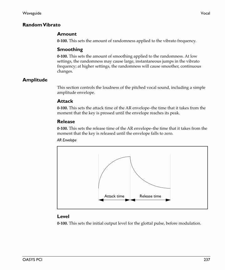
Waveguide Vocal
Random Vibrato
Amount0-100. This sets the amount of randomness applied to the vibrato frequency.
Smoothing0-100. This sets the amount of smoothing applied to the randomness. At low settings, the randomness may cause large, instantaneous jumps in the vibrato frequency; at higher settings, the randomness will cause smoother, continuous changes.
AmplitudeThis section controls the loudness of the pitched vocal sound, including a simple amplitude envelope.
Attack0-100. This sets the attack time of the AR envelope–the time that it takes from the moment that the key is pressed until the envelope reaches its peak.
Release0-100. This sets the release time of the AR envelope–the time that it takes from the moment that the key is released until the envelope falls to zero.
AR Envelope
Level0-100. This sets the initial output level for the glottal pulse, before modulation.
Attack time Release time
OASYS PCI 237

Vocal Waveguide
Eng
lish
Level ModList of Modulation Sources. This sets the modulation source for controlling the glottal pulse output level. For a complete list, please see “Modulation Sources” on page 2.
Mod Amount0-100. This sets the amount by which the mod source affects the glottal pulse output level.
NoiseThis section controls the timbre and level of the breath noise. The timbre of the noise is shaped by a 12dB per octave, resonant lowpass filter.
Frequency 0-100. This controls the cutoff frequency of the 12dB per octave lowpass filter. Frequencies above the cutoff are cut, and frequencies below the cutoff are passed through unchanged.
Generally speaking, the lower the cutoff, the darker the sound; the higher the cutoff, the brighter the sound.
Resonance0-100. This controls the resonance of the filter. At 0, the filter will not resonate at all; at 100, it will be very resonant.
Level0-100. This sets the initial output level for the breath noise, before modulation.
Level ModList of Modulation Sources. This sets the modulation source for controlling the breath noise output level. For a complete list, please see “Modulation Sources” on page 2.
Mod Amount0-100. This sets the amount by which the mod source affects the breath noise output level.
FormantThis section controls the shape of the mouth and throat, to create different vowel sounds, or “formants.” You can fade between different formants in real time, using MIDI modulation and/or a dedicated LFO.
There is a single formant filter for the entire Patch, regardless of the number of voices assigned. If the number of voices is set to 6, for instance, you will be able to
238 OASYS PCI
Waveguide Vocal
play six notes creating individual glottal pulses and breath noises, which will then all go through a single formant filter.
Input Trim0-100. This sets the input level to the formant filter. If the filter resonance is high, you may need to turn down the input to prevent clipping.
Formant ShapeThese parameters assign vowel sounds to the minimum, center, and maximum values of the manual control, the Shape X-Fade controller, and the LFO. For example, let’s say that Mod Wheel is selected as the modulation source, and Voice Top is set to a, Voice Center is set to i, and Voice Bottom is set to u. Moving the wheel up from 0 will then produce the vowel sounds “u”, “i”, and then “a.”
Bottoma, e, i, u, eee, straight. This is the vowel sound at the minimum value of the controller. “Straight” means that the glottal pulse and breath noise will be heard directly, without any formants.
Centera, e, i, u, eee, straight. This is the vowel sound at the middle value of the controller.
Topa, e, i, u, eee, straight. This is the vowel sound at the maximum value of the controller.
Vocal SizeSmall, Normal, Big. This controls the size of the throat creating the formants. Small is like a small child, Normal is like an average-sized adult, and Big is like a very large man.
Damping0.0-100.0. This sets the amount of high-frequency damping within the formant filter.
Resonance0.0-100.0. This sets the intensity of the vowel resonance. Higher resonance settings will add more character to the sound.
Formant Control
Manual0-100. This sets the initial position within the Formant Shape, between the bottom, center, and top positions.
Shape X-FadeList of Modulation Sources. This sets the modulation source for controlling the formant shape. For a complete list, please see “Modulation Sources” on page 2.
OASYS PCI 239

Vocal Waveguide
Eng
lish
LFO
LFO Freq0.00-4.00 Hz. This sets the frequency, or speed, of the LFO.
LFO Shape+/-100. This adjusts the shape of the LFO waveform. Positive values shape the curve so that it spends more time in the “up” part of the cycle, and negative values make it spend more time in the “down” part of the cycle, as shown below.
LFO Shape
LFO Amt0-100. This sets the amount by which the LFO affects the formant shape.
Output FiltersThe highpass and lowpass filters control the output of the formant filter, and thus the output of the entire Patch.
Highpass0.00-100.00. This controls the cutoff frequency of the highpass filter. Frequencies below the cutoff will be attenuated, and frequencies above the cutoff will pass through unchanged.
Lowpass0.00-100.00. This controls the cutoff frequency of the lowpass filter. Frequencies above the cutoff are attenuated, and frequencies below the cutoff are passed through unchanged.
LFO Shape = 0 to +100 LFO Shape = 0 to -100
Sine Waveform
240 OASYS PCI

Effects

Amp & Speaker
Eng
lish
Amp & Speaker
242 OASYS PCI

Amp & Speaker Guitar Amp
Guitar AmpThis effect simulates the frequency response characteristics of guitar amplifiers. You can obtain a realistic guitar amplifier sound. It’s also effective for organ sounds.
Input
SourceLeft, L + R. This is a mono-in, mono-out effect. Stereo signals are preserved in the dry mix at the output, but the effect itself has only a single, mono input.
When this is set to Left, only the left channel will be routed into the effect.
When this is set to L + R, the left and right channels will be summed together, and then routed into the effect.
Level-INF, -69.0 to 0.0dB. This sets the input level for the effect. It does not affect the dry signal.
Amp Simulator
Amplifier TypeSS, EL84, 6L6. Selects the type of guitar amplifier.
Output
Wet/DryDry, 1:99-99:1, Wet. This sets the balance between the effect and the dry signal.
Wet/Dry ModList of Modulation Sources. This sets the modulation source for controlling the wet/dry mix. For a complete list, please see “Modulation Sources” on page 2.
Mod Amount+/-100. This sets the amount by which the mod source affects the wet/dry mix.
OASYS PCI 243

St Guitar Amp Amp & Speaker
Eng
lish
St Guitar AmpThis is a stereo-in, stereo-out amp simulator.
Input
Level-INF, -69.0 to 0.0dB. This sets the input level for the effect. It does not affect the dry signal.
Amp Simulator
Amplifier TypeSS, EL84, 6L6. Selects the type of guitar amplifier.
Output
Wet/DryDry, 1:99-99:1, Wet. This sets the balance between the effect and the dry signal.
Wet/Dry ModList of Modulation Sources. This sets the modulation source for controlling the wet/dry mix. For a complete list, please see “Modulation Sources” on page 2.
Mod Amount+/-100. This sets the amount by which the mod source affects the wet/dry mix.
244 OASYS PCI

Chorus

4-Tap Chorus Chorus
Eng
lish
4-Tap ChorusThis effect has four chorus blocks, each with a different LFO phase. You can create a complex stereo image by setting each block’s delay time, depth, output level, and pan individually. You can also set some of the chorus blocks to combine the chorus and delay effects.
Input
SourceLeft, L + R. This is a mono-in, stereo-out effect. Stereo signals are preserved in the dry mix at the output, but the chorus effect itself has only a single, mono input.
When this is set to Left, only the left channel will be routed into the effect.
When this is set to L + R, the left and right channels will be summed together, and then routed into the effect.
Level-INF, -69.0 to 0.0dB. This sets the input level for the effect. It does not affect the dry signal.
Taps 1-4
Delay0.0-440.0ms. This sets the delay time for the tap, in milliseconds.
Depth0-100. This controls the depth of LFO pitch modulation for the tap.
Level0-100. This sets the output volume level for the tap.
Pan0-100. This sets the stereo output position for the tap.
Tap 1 Feedback
Feedback+/-100. This sets the delay feedback for tap 1.
Feedback ModList of Modulation Sources. This sets the modulation source for controlling tap 1’s delay feedback. For a complete list, please see “Modulation Sources” on page 2.
246 OASYS PCI

Chorus 4-Tap Chorus
Mod Amt+/-100. This sets the amount by which the mod source affects tap 1’s delay feedback.
LFO
Frequency0.00-20.00Hz. This controls the speed of the LFOs.
Output
Wet/DryDry, 1:99-99:1, Wet. This sets the balance between the effect and the dry signal.
Wet/Dry ModList of Modulation Sources. This sets the modulation source for controlling the wet/dry mix. For a complete list, please see “Modulation Sources” on page 2.
Mod Amount+/-100. This sets the amount by which the mod source affects the wet/dry mix.
OASYS PCI 247

6-Tap Chorus Chorus
Eng
lish
6-Tap ChorusThis effect has six chorus blocks with different LFO phases. You can produce a complex stereo image by setting a different delay time and depth for each block.
Input
SourceLeft, L + R. This is a mono-in, stereo-out effect. Stereo signals are preserved in the dry mix at the output, but the chorus effect itself has only a single, mono input.
When this is set to Left, only the left channel will be routed into the effect.
When this is set to L + R, the left and right channels will be summed together, and then routed into the effect.
Level-INF, -69.0 to 0.0dB. This sets the input level for the effect. It does not affect the dry signal.
Tap 1
Delay0.0-670.0ms. This sets the delay time for Tap 1, in milliseconds.
Depth0-100. This controls the depth of LFO pitch modulation for Tap 1.
Level0-100. This sets the output volume level for Tap 1.
Level ModList of Modulation Sources. This sets the modulation source for controlling the output levels for all of the taps, 1 through 6. For a complete list of mod sources, please see “Modulation Sources” on page 2.
Mod Amt+/-100. This sets the amount by which the mod source affects the output level of tap 1.
248 OASYS PCI

Chorus 6-Tap Chorus
Taps 2-6Each of Taps 2-6 has its own LFO, running at a preset phase offset from Tap 1’s LFO, as shown below:
Delay0.0-670.0ms. This sets the delay time for the tap, in milliseconds.
Depth0-100. This controls the depth of LFO pitch modulation for the tap.
Level0-100. This sets the output volume level for the tap.
Mod Amt+/-100. This sets the amount by which the mod source affects the output level of each individual tap. All of the taps use the mod source selected for Tap 1, as described above. You can use the level modulation to smoothly crossfade between (for instance) a 4-phase chorus and a two-tap delay.
Tap 1 Feedback
Feedback+/-100. This sets the delay feedback for tap 1.
Feedback ModList of Modulation Sources. This sets the modulation source for controlling tap 1’s delay feedback. For a complete list, please see “Modulation Sources” on page 2.
Mod Amt+/-100. This sets the amount by which the mod source affects tap 1’s delay feedback.
Panning
Panning Preseta-d. This controls the panning of the six taps, offering various combinations of stereo images. Each entry shows the relative panning of the taps, from left to right.
Tap 1 2 3 4 5 6
Phase 0° 180° 60° 240° 120° 300°
OASYS PCI 249

6-Tap Chorus Chorus
Eng
lish
Spread+/-100. This controls the width of the effect’s stereo image.
LFO
Frequency0.00-20.00Hz. This controls the speed of the LFOs.
Output
Wet/DryDry, 1:99-99:1, Wet. This sets the balance between the effect and the dry signal.
Wet/Dry ModList of Modulation Sources. This sets the modulation source for controlling the wet/dry mix. For a complete list, please see “Modulation Sources” on page 2.
Mod Amount+/-100. This sets the amount by which the mod source affects the wet/dry mix.
250 OASYS PCI

Chorus Chorus
ChorusThis effect adds thickness and warmth to the sound by modulating the delay time of the input signal.
Input
SourceLeft, L + R. This is a mono-in, mono-out effect. Stereo signals are preserved in the dry mix at the output, but the chorus effect itself has only a single, mono input.
When this is set to Left, only the left channel will be routed into the effect.
When this is set to L + R, the left and right channels will be summed together, and then routed into the effect.
Level-INF, -69.0 to 0.0dB. This sets the input level for the effect. It does not affect the dry signal.
Chorus
Delay0.0-50.0ms. This sets the delay time for the chorus, in milliseconds.
Depth0-100. This controls the depth of LFO pitch modulation.
Depth ModList of Modulation Sources. This sets the modulation source for controlling the LFO depth. For a complete list, please see “Modulation Sources” on page 2.
Mod Amount+/-100. This sets the amount by which the mod source affects the LFO depth.
LFO
Frequency0.00-20.00Hz. This controls the speed of the LFO.
Frequency ModList of Modulation Sources. This sets the modulation source for controlling the LFO speed. For a complete list, please see “Modulation Sources” on page 2.
OASYS PCI 251

Chorus Chorus
Eng
lish
Mod Amount+/-100. This sets the amount by which the mod source affects the LFO speed.
Output
ModeMono, Stereo. This controls whether the effect output is mono or simulated stereo.
When this is set to Mono, the output is in mono.
When this is set to Stereo, the output is simulated stereo, with the right effect output inverted. Note that this simulated stereo effect is not mono-compatible.
Wet/DryDry, 1:99-99:1, Wet. This sets the balance between the effect and the dry signal.
Wet/Dry ModList of Modulation Sources. This sets the modulation source for controlling the wet/dry mix. For a complete list, please see “Modulation Sources” on page 2.
Mod Amount+/-100. This sets the amount by which the mod source affects the wet/dry mix.
252 OASYS PCI

Chorus EQ Chorus
EQ ChorusThis is a mono-in, mono-out chorus, combined with a two-band shelving EQ.
Input
SourceLeft, L + R. This is a mono-in, mono-out effect. Stereo signals are preserved in the dry mix at the output, but the chorus effect itself has only a single, mono input.
When this is set to Left, only the left channel will be routed into the effect.
When this is set to L + R, the left and right channels will be summed together, and then routed into the effect.
Level-INF, -69.0 to 0.0dB. This sets the input level for the effect. It does not affect the dry signal.
Pre EQ
Low Freq20-2000Hz. The frequency of the low shelving EQ.
Low Gain+/-18.1dB. The gain of the low shelving EQ.
High Freq5000-20,000Hz. The frequency of the high shelving EQ.
High Gain+/-18.1dB. The gain of the high shelving EQ.
Chorus
Delay0.0-50.0ms. This sets the delay time for the chorus, in milliseconds.
Depth0-100. This controls the depth of LFO pitch modulation.
Depth ModList of Modulation Sources. This sets the modulation source for controlling the LFO depth. For a complete list, please see “Modulation Sources” on page 2.
OASYS PCI 253

EQ Chorus Chorus
Eng
lish
Mod Amount+/-100. This sets the amount by which the mod source affects the LFO depth.
LFO
WaveformTriangle, Sine. This selects the shape of the LFO.
Frequency0.02-20.00Hz. This controls the speed of the LFOs.
Frequency ModList of Modulation Sources. This sets the modulation source for controlling the LFO speed. For a complete list, please see “Modulation Sources” on page 2.
Mod Amount+/-100. This sets the amount by which the mod source affects the LFO speed.
Output
ModeMono, Stereo. This controls whether the effect output is mono or simulated stereo.
When this is set to Mono, the output is in mono.
When this is set to Stereo, the output is simulated stereo, with the right effect output inverted. Note that this simulated stereo effect is not mono-compatible.
Wet/DryDry, 1:99-99:1, Wet. This sets the balance between the effect and the dry signal.
Wet/Dry ModList of Modulation Sources. This sets the modulation source for controlling the wet/dry mix. For a complete list, please see “Modulation Sources” on page 2.
Mod Amount+/-100. This sets the amount by which the mod source affects the wet/dry mix.
254 OASYS PCI

Chorus Harmonic Chorus
Harmonic ChorusThis effect applies chorus only to higher frequencies. This can be used to apply a chorus effect to a bass sound without making the sound thinner. You can also add feedback, to turn the chorus into a flanger.
Input
SourceLeft, L + R. This is a mono-in, mono-out effect. Stereo signals are preserved in the dry mix at the output, but the chorus effect itself has only a single, mono input.
When this is set to Left, only the left channel will be routed into the effect.
When this is set to L + R, the left and right channels will be summed together, and then routed into the effect.
Level-INF, -69.0 to 0.0dB. This sets the input level for the effect. It does not affect the dry signal.
Hi/Low Xover0-100. This sets frequency for the crossover filter. Only the audio above the crossover point is sent through the chorus; audio below the crossover point is sent directly to the outputs.
Chorus
Delay0.0-50.0ms. This sets the delay time for the chorus, in milliseconds.
Depth0-100. This controls the depth of LFO pitch modulation.
Depth ModList of Modulation Sources. This sets the modulation source for controlling the LFO depth. For a complete list, please see “Modulation Sources” on page 2.
Mod Amount+/-100. This sets the amount by which the mod source affects the LFO depth.
Sets the feedback amount of the chorus block. Increasing the feedback will allow you to use the effect as a flanger.
OASYS PCI 255

Harmonic Chorus Chorus
Eng
lish
Feedback+/-100. This sets the feedback amount of the chorus. Increasing the feedback will allow you to use the effect as a flanger.
Damping0-100. This controls the high-frequency damping in the feedback path.
Levels
Low Band0-100. This sets the output level for the dry, unchorused low band.
High Band0-100. This sets the output level for the chorused high band.
Output
ModeMono, Stereo. This controls whether the effect output is mono or simulated stereo.
When this is set to Mono, the output is in mono.
When this is set to Stereo, the output is simulated stereo, with the right effect output inverted. Note that this simulated stereo effect is not mono-compatible.
Wet/DryDry, 1:99-99:1, Wet. This sets the balance between the effect and the dry signal.
Wet/Dry ModList of Modulation Sources. This sets the modulation source for controlling the wet/dry mix. For a complete list, please see “Modulation Sources” on page 2.
Mod Amount+/-100. This sets the amount by which the mod source affects the wet/dry mix.
256 OASYS PCI

Chorus St 2-Band Chor
St 2-Band ChorThis is a stereo-in, stereo-out chorus effect, with completely separate choruses for high and low frequencies. Thick, fine chorus effects can be created when this effect is applied to strings or ensemble sounds.
Input
Level-INF, -69.0 to 0.0dB. This sets the input level for the effect. It does not affect the dry signal.
Hi/Low Xover0-100. This sets frequency for the crossover filter. Audio below the crossover point is sent through the Low Band Chorus, and audio above the crossover point is sent through the High Band Chorus.
High Band Chorus
Left Delay0.0-50.0ms. This sets the delay time for the left channel, in milliseconds.
Right Delay0.0-50.0ms. This sets the delay time for the right channel, in milliseconds.
WaveformTriangle, Sine. This selects the shape of the LFO.
Depth0-100. This controls the depth of LFO pitch modulation.
Frequency0.00-20.00Hz. This controls the speed of the LFO.
L/R Phase+/-180. This sets the phase difference between the LFOs for the right and left channels. Off-setting the phase between the two, as shown below, enhances the stereo effect.
OASYS PCI 257

St 2-Band Chor Chorus
Eng
lish
LFO Phase
Low Band Chorus
Left Delay0.0-50.0ms. This sets the delay time for the left channel, in milliseconds.
Right Delay0.0-50.0ms. This sets the delay time for the right channel, in milliseconds.
WaveformTriangle, Sine. This selects the shape of the LFO.
Depth0-100. This controls the depth of LFO pitch modulation.
Frequency0.00-20.00Hz. This controls the speed of the LFO.
L/R Phase+/-180. This sets the phase difference between the LFOs for the right and left channels. Off-setting the phase between the two, as shown above, enhances the stereo effect.
0° +90° +180°
0°–90°–180°
258 OASYS PCI

Chorus St 2-Band Chor
Depth Modulation
ModulateHigh Band, Low Band, Both. This selects whether depth modulation affects just the high band chorus, just the low band chorus, or both bands at once.
Depth ModList of Modulation Sources. This sets the modulation source for controlling the LFO depth. For a complete list, please see “Modulation Sources” on page 2.
Mod Amount+/-100. This sets the amount by which the mod source affects the LFO depth.
Frequency Modulation
ModulateHigh Band, Low Band, Both. This selects whether frequency modulation affects just the high band chorus, just the low band chorus, or both bands at once.
Frequency ModList of Modulation Sources. This sets the modulation source for controlling the LFO speed. For a complete list, please see “Modulation Sources” on page 2.
Mod Amount+/-100. This sets the amount by which the mod source affects the LFO speed.
Output
Wet/DryDry, 1:99-99:1, Wet. This sets the balance between the effect and the dry signal.
Wet/Dry ModList of Modulation Sources. This sets the modulation source for controlling the wet/dry mix. For a complete list, please see “Modulation Sources” on page 2.
Mod Amount+/-100. This sets the amount by which the mod source affects the wet/dry mix.
OASYS PCI 259

St Bi-Phase Chr Chorus
Eng
lish
St Bi-Phase ChrThis stereo-in, stereo-out chorus effect adds two different LFOs together. You can set the Frequency and Depth parameters for each LFO individually. Depending on the setting of these LFOs, very complex waveforms will create an analog-type, unstable modulated sound.
Input
Level-INF, -69.0 to 0.0dB. This sets the input level for the effect. It does not affect the dry signal.
Delay
Left0.0-50.0ms. This sets the delay time for the left channel, in milliseconds.
Right0.0-50.0ms. This sets the delay time for the right channel, in milliseconds.
Stereo Bi-Phase Mod
LFO 1 Depth0-100. This controls the depth of LFO 1’s pitch modulation.
LFO 2 Depth0-100. This controls the depth of LFO 2’s pitch modulation.
Feedback+/-100. This sets the feedback amount of the chorus. Increasing the feedback will change the chorus into a flanger.
Damping0-100. This controls the high-frequency damping in the feedback path.
Depth Modulation
Mod SourceList of Modulation Sources. This sets the modulation source for controlling the LFO depth. For a complete list, please see “Modulation Sources” on page 2.
LFO 1 Amt+/-100. This sets the amount by which the mod source affects LFO 1’s depth.
260 OASYS PCI

Chorus St Bi-Phase Chr
LFO 2 Amt+/-100. This sets the amount by which the mod source affects LFO 2’s depth.
LFO 1
WaveformTriangle, Sine. This selects the shape of LFO 1.
Frequency0.00-20.00Hz. This controls the speed of LFO 1.
Frequency ModList of Modulation Sources. This sets the modulation source for controlling the speed of LFO 1. For a complete list, please see “Modulation Sources” on page 2.
Amount+/-100. This sets the amount by which the mod source affects the speed of LFO 1.
LFO Phase
1 <-> 2+/-180. This sets the phase difference between the two LFOs. Off-setting the phase between the two changes the resulting complex waveform.
LFO 2
WaveformTriangle, Sine. This selects the shape of LFO 2.
Frequency0.00-20.00Hz. This controls the speed of LFO 2.
Frequency ModList of Modulation Sources. This sets the modulation source for controlling the speed of LFO 2. For a complete list, please see “Modulation Sources” on page 2.
Amount+/-100. This sets the amount by which the mod source affects the speed of LFO 2.
OASYS PCI 261

St Bi-Phase Chr Chorus
Eng
lish
Interaction between the two LFOs
Output
Wet/DryDry, 1:99-99:1, Wet. This sets the balance between the effect and the dry signal.
Wet/Dry ModList of Modulation Sources. This sets the modulation source for controlling the wet/dry mix. For a complete list, please see “Modulation Sources” on page 2.
Mod Amount+/-100. This sets the amount by which the mod source affects the wet/dry mix.
Invert Wet PhaseOn, Off. This inverts the phase of the chorused signal, changing the timbre when combined with the dry sound.
LFO1
LFO2
Depth1
Depth2
+
262 OASYS PCI

Chorus St Chorus
St ChorusThis is a stereo-in, stereo-out chorus. You can enhance the stereo effect by offsetting the phase of the left and right LFOs from each other.
Input
Level-INF, -69.0 to 0.0dB. This sets the input level for the effect. It does not affect the dry signal.
Stereo Chorus
Left Delay0.0-50.0ms. This sets the delay time for the left channel, in milliseconds.
Right Delay0.0-50.0ms. This sets the delay time for the right channel, in milliseconds.
Depth0-100. This controls the depth of LFO pitch modulation.
Depth ModList of Modulation Sources. This sets the modulation source for controlling the LFO depth. For a complete list, please see “Modulation Sources” on page 2.
Mod Amount+/-100. This sets the amount by which the mod source affects the LFO depth.
Spread+/-100. This controls the width of the effect’s stereo image, without affecting the dry signal. A value of +100 gives the widest stereo image, and a value of 0 collapses the output to mono. Negative values will reverse the left and right channels of the effect output.
You can also use the L/R Phase parameter to enhance the stereo effect.
LFO
WaveformTriangle, Sine. This selects the shape of the LFO.
OASYS PCI 263

St Chorus Chorus
Eng
lish
L/R Phase+/-180. This sets the phase difference between the LFOs for the right and left channels. Off-setting the phase between the two, as shown below, enhances the stereo effect.
LFO Phase
Frequency0.00-20.00Hz. This controls the speed of the LFOs.
Frequency ModList of Modulation Sources. This sets the modulation source for controlling the LFO speed. For a complete list, please see “Modulation Sources” on page 2.
Mod Amount+/-100. This sets the amount by which the mod source affects the LFO speed.
Output
Wet/DryDry, 1:99-99:1, Wet. This sets the balance between the effect and the dry signal.
Wet/Dry ModList of Modulation Sources. This sets the modulation source for controlling the wet/dry mix. For a complete list, please see “Modulation Sources” on page 2.
Mod Amount+/-100. This sets the amount by which the mod source affects the wet/dry mix.
0° +90° +180°
0°–90°–180°
264 OASYS PCI

Chorus St EQ Chorus
St EQ ChorusThis is a stereo chorus with a two-band shelving EQ. You can add spread to the sound by offsetting the phase of the left and right LFOs from each other.
Input
Level-INF, -69.0 to 0.0dB. This sets the input level for the effect. It does not affect the dry signal.
Pre EQ
Low Freq20…2000Hz. The frequency of the low shelving EQ.
Low Gain+/-18.1dB. The gain of the low shelving EQ.
High Freq5000…20,000Hz. The frequency of the high shelving EQ.
High Gain+/-18.1dB, The gain of the high shelving EQ.
Chorus
Left Delay0.0-50.0ms. This sets the delay time for the left channel, in milliseconds.
Right Delay0.0-50.0ms. This sets the delay time for the right channel, in milliseconds.
Depth0-100. This controls the depth of LFO pitch modulation.
Depth ModList of Modulation Sources. This sets the modulation source for controlling the LFO depth. For a complete list, please see “Modulation Sources” on page 2.
Mod Amount+/-100. This sets the amount by which the mod source affects the LFO depth.
OASYS PCI 265

St EQ Chorus Chorus
Eng
lish
Spread+/-100. This controls the width of the effect’s stereo image, without affecting the dry signal. A value of +100 gives the widest stereo image, and a value of 0 collapses the output to mono. Negative values will reverse the left and right channels of the effect output.
LFO
WaveformTriangle, Sine. This selects the shape of the LFO.
L/R Phase+/-180. This sets the phase difference between the LFOs for the right and left channels. Off-setting the phase between the two, as shown below, enhances the stereo effect.
LFO Phase
Frequency0.00-20.00Hz. This controls the speed of the LFOs.
Frequency ModList of Modulation Sources. This sets the modulation source for controlling the LFO speed. For a complete list, please see “Modulation Sources” on page 2.
Mod Amount+/-100. This sets the amount by which the mod source affects the LFO speed.
0° +90° +180°
0°–90°–180°
266 OASYS PCI

Chorus St EQ Chorus
Output
Wet/DryDry, 1:99-99:1, Wet. This sets the balance between the effect and the dry signal.
Wet/Dry ModList of Modulation Sources. This sets the modulation source for controlling the wet/dry mix. For a complete list, please see “Modulation Sources” on page 2.
Mod Amount+/-100. This sets the amount by which the mod source affects the wet/dry mix.
OASYS PCI 267

St HarmonicChr Chorus
Eng
lish
St HarmonicChrThis is a stereo-in, stereo-out harmonic chorus, which applies chorus only to higher frequencies. It can be used to apply a chorus effect to a bass sound without making the sound thinner. You can also add feedback, to turn the chorus into a flanger.
Shifting the left and right LFO phases from each other will enhance the stereo width.
Input
Level-INF, -69.0 to 0.0dB. This sets the input level for the effect. It does not affect the dry signal.
Hi/Low Xover0-100. This sets frequency for the crossover filter. Only the audio above the crossover point is sent through the chorus; audio below the crossover point is sent directly to the outputs.
Stereo Harmonic Chorus
Left Delay0.0-50.0ms. This sets the delay time for the left channel, in milliseconds.
Right Delay0.0-50.0ms. This sets the delay time for the right channel, in milliseconds.
Depth0-100. This controls the depth of LFO pitch modulation.
Depth ModList of Modulation Sources. This sets the modulation source for controlling the LFO depth. For a complete list, please see “Modulation Sources” on page 2.
Mod Amount+/-100. This sets the amount by which the mod source affects the LFO depth.
Feedback+/-100. This sets the feedback amount of the chorus. Increasing the feedback will change the chorus into a flanger.
Damping0-100. This controls the high-frequency damping in the feedback path.
268 OASYS PCI

Chorus St HarmonicChr
LFO
WaveformTriangle, Sine. This selects the shape of the LFO.
L/R Phase+/-180. This sets the phase difference between the LFOs for the right and left channels. Off-setting the phase between the two, as shown below, enhances the stereo effect.
LFO Phase
Frequency0.00-20.00Hz. This controls the speed of the LFOs.
Frequency ModList of Modulation Sources. This sets the modulation source for controlling the LFO speed. For a complete list, please see “Modulation Sources” on page 2.
Mod Amount+/-100. This sets the amount by which the mod source affects the LFO speed.
Levels
Low Band0-100. This sets the output level for the dry, unchorused low band.
0° +90° +180°
0°–90°–180°
OASYS PCI 269

St HarmonicChr Chorus
Eng
lish
High Band0-100. This sets the output level for the chorused high band.
Output
Wet/DryDry, 1:99-99:1, Wet. This sets the balance between the effect and the dry signal.
Wet/Dry ModList of Modulation Sources. This sets the modulation source for controlling the wet/dry mix. For a complete list, please see “Modulation Sources” on page 2.
Mod Amount+/-100. This sets the amount by which the mod source affects the wet/dry mix.
270 OASYS PCI

Chorus St Step Chorus
St Step ChorusThis is a stereo-in, stereo-out chorus, with a step effect on the LFO. You can enhance the stereo effect by offsetting the phase of the left and right LFOs from each other.
Input
Level-INF, -69.0 to 0.0dB. This sets the input level for the effect. It does not affect the dry signal.
Stereo Chorus
Left Delay0.0-50.0ms. This sets the delay time for the left channel, in milliseconds.
Right Delay0.0-50.0ms. This sets the delay time for the right channel, in milliseconds.
Depth0-100. This controls the depth of LFO pitch modulation.
Depth ModList of Modulation Sources. This sets the modulation source for controlling the LFO depth. For a complete list, please see “Modulation Sources” on page 2.
Mod Amount+/-100. This sets the amount by which the mod source affects the LFO depth.
Spread+/-100. This controls the width of the effect’s stereo image, without affecting the dry signal. A value of +100 gives the widest stereo image, and a value of 0 collapses the output to mono. Negative values will reverse the left and right channels of the effect output.
You can also use the L/R Phase parameter to enhance the stereo effect.
LFO
WaveformTriangle, Sine. This selects the shape of the LFO.
OASYS PCI 271

St Step Chorus Chorus
Eng
lish
L/R Phase+/-180. This sets the phase difference between the LFOs for the right and left channels. Off-setting the phase between the two, as shown below, enhances the stereo effect.
LFO Phase
Frequency0.00-20.00Hz. This controls the speed of the LFOs.
Frequency ModList of Modulation Sources. This sets the modulation source for controlling the LFO speed. For a complete list, please see “Modulation Sources” on page 2.
Mod Amount+/-100. This sets the amount by which the mod source affects the LFO speed.
Step LFOOn, Off. This turns the step effect on and off.
Step Freq0.00-50.00Hz. This sets the frequency for the step waveform.
Output
Wet/DryDry, 1:99-99:1, Wet. This sets the balance between the effect and the dry signal.
0° +90° +180°
0°–90°–180°
272 OASYS PCI

Chorus St Step Chorus
Wet/Dry ModList of Modulation Sources. This sets the modulation source for controlling the wet/dry mix. For a complete list, please see “Modulation Sources” on page 2.
Mod Amount–100…+100. This sets the amount by which the mod source affects the wet/dry mix.
OASYS PCI 273

St Step Chor 2 Chorus
Eng
lish
St Step Chor 2This is a stereo-in, stereo-out chorus effect, with completely separate choruses for high and low frequencies. You can also use the high-range chorus as a step chorus, employing a step-shape LFO waveform. Thick, fine chorus effects can be created when this effect is applied to strings or ensemble sounds.
Input
Level-INF, -69.0 to 0.0dB. This sets the input level for the effect. It does not affect the dry signal.
Hi/Low Xover0-100. This sets frequency for the crossover filter. Audio below the crossover point is sent through the Low Band Chorus, and audio above the crossover point is sent through the High Band Chorus.
High Band Chorus
Left Delay0.0-50.0ms. This sets the delay time for the left channel, in milliseconds.
Right Delay0.0-50.0ms. This sets the delay time for the right channel, in milliseconds.
WaveformTriangle, Sine. This selects the shape of the LFO.
Depth0-100. This controls the depth of LFO pitch modulation.
Frequency0.00-20.00Hz. This controls the speed of the LFO.
L/R Phase+/-180. This sets the phase difference between the LFOs for the right and left channels. Off-setting the phase between the two, as shown below, enhances the stereo effect.
274 OASYS PCI

Chorus St Step Chor 2
LFO Phase
Step LFOOn, Off. This turns the step effect on and off.
Step Freq0.00-50.00Hz. This sets the frequency for the step waveform.
Level0-100. This sets the output level for the high band chorus.
Low Band Chorus
Left Delay0.0-50.0ms. This sets the delay time for the left channel, in milliseconds.
Right Delay0.0-50.0ms. This sets the delay time for the right channel, in milliseconds.
WaveformTriangle, Sine. This selects the shape of the LFO.
Depth0-100. This controls the depth of LFO pitch modulation.
Frequency0.00-20.00Hz. This controls the speed of the LFO.
0° +90° +180°
0°–90°–180°
OASYS PCI 275

St Step Chor 2 Chorus
Eng
lish
L/R Phase+/-180. This sets the phase difference between the LFOs for the right and left channels. Off-setting the phase between the two, as shown above, enhances the stereo effect.
Level0-100. This sets the output level for the low band chorus.
Depth Modulation
ModulateHigh Band, Low Band, Both. This selects whether depth modulation affects just the high band chorus, just the low band chorus, or both bands at once.
Depth ModList of Modulation Sources. This sets the modulation source for controlling the LFO depth. For a complete list, please see “Modulation Sources” on page 2.
Mod Amount+/-100. This sets the amount by which the mod source affects the LFO depth.
Frequency Modulation
ModulateHigh Band, Low Band, Both. This selects whether frequency modulation affects just the high band chorus, just the low band chorus, or both bands at once.
Frequency ModList of Modulation Sources. This sets the modulation source for controlling the LFO speed. For a complete list, please see “Modulation Sources” on page 2.
Mod Amount+/-100. This sets the amount by which the mod source affects the LFO speed.
Output
Wet/DryDry, 1:99-99:1, Wet. This sets the balance between the effect and the dry signal.
Wet/Dry ModList of Modulation Sources. This sets the modulation source for controlling the wet/dry mix. For a complete list, please see “Modulation Sources” on page 2.
Mod Amount+/-100. This sets the amount by which the mod source affects the wet/dry mix.
276 OASYS PCI

Chorus St TempoChorus
St TempoChorusThis is a stereo-in, stereo-out chorus with a complex, tempo-controlled LFO. For more information on syncing LFOs to MIDI, see “MIDI Tempo LFOs” on page 5.
Input
Level-INF, -69.0 to 0.0dB. This sets the input level for the effect. It does not affect the dry signal.
Delay
Left0.0-50.0ms. This sets the delay time for the left channel, in milliseconds.
Right0.0-50.0ms. This sets the delay time for the right channel, in milliseconds.
Stereo Chorus
Depth0-100. This controls the depth of LFO pitch modulation.
Depth ModList of Modulation Sources. This sets the modulation source for controlling the LFO depth. For a complete list, please see “Modulation Sources” on page 2.
Mod Amount+/-100. This sets the amount by which the mod source affects the LFO depth.
Spread+/-100. This controls the width of the effect’s stereo image, without affecting the dry signal. A value of +100 gives the widest stereo image, and a value of 0 collapses the output to mono. Negative values will reverse the left and right channels of the effect output.
You can also use the L/R Phase parameter to enhance the stereo effect.
LFO
General
WaveformTriangle, Sine. This selects the shape of the LFO.
OASYS PCI 277

St TempoChorus Chorus
Eng
lish
LFO ControlFrequency Knob, Manual Tempo, MIDI Tempo. The LFO speed can be controlled either by the Frequency knob (including the mod source), the Manual Tempo knob, or by MIDI Tempo (derived from MIDI clocks).
If this is set to Frequency Knob, then the LFO speed will be controlled by the settings in the Frequency section, including the mod source and amount.
If this is set to Manual Tempo, then the Manual Tempo knob will set the basic tempo, and the note value set in the Subdivisions menu will control the LFO speed.
If this is set to MIDI Tempo, then incoming MIDI Clocks will set the basic tempo, and the note value set in the Subdivisions menu will control the LFO speed.
Phase
Initial PhaseThis sets the point in the waveform at which the LFO starts. Whenever the Phase Reset controller is received, the LFO will start from the Initial Phase point.
L/R Phase+/-180. This sets the phase difference between the LFOs for the right and left channels. Off-setting the phase between the two, as shown below, enhances the stereo effect.
When using the LFO with tempo, the L/R Phase also creates a rhythmic offset between the left and right channels. For instance, a 1/4 note LFO with an L/R Phase of +180 creates alternating stereo 8th notes.
LFO Phase
0° +90° +180°
0°–90°–180°
278 OASYS PCI

Chorus St TempoChorus
Phase ResetList of Modulation Sources. This sets the MIDI controller which will reset the LFO’s phase to the Initial Phase point. You can use this to trigger the LFO from a MIDI sequencer, so that it always starts at the same point. This is especially useful in conjunction with MIDI Tempo synchronization. For a complete list of mod sources, please see “Modulation Sources” on page 2.
To make sure that the LFO’s phase is correct when working with a sequencer, it’s best to include the phase reset controller every few bars in the sequence, so that no matter where you start playback, the LFO will be reset appropriately.
Waveforms and Phase
FrequencyThe controls in the Frequency section only apply when the LFO Control is set to Frequency Knob.
Frequency0.00-20.00Hz. This controls the speed of the LFO when the LFO Control is set to Frequency Knob.
Frequency ModList of Modulation Sources. This sets the modulation source for controlling the LFO speed. For a complete list, please see “Modulation Sources” on page 2.
Mod Amount+/-100. This sets the amount by which the mod source affects the LFO speed.
Manual Tempo40-240 bpm. This sets the tempo when the LFO Control is set to Manual Tempo.
0˚ 90˚ 180˚-90˚-180˚
Triangle Sine
0˚ 90˚ 180˚-90˚-180˚
OASYS PCI 279

St TempoChorus Chorus
Eng
lish
Subdivision1/32, 1/32 dotted, 1/16, 1/16 dotted, 1/16 triplet, 1/8, 1/8 dotted, 1/8 triplet, 1/4, 1/4 dotted, 1/4 triplet, 1/2, 1/2 dotted, 1/2 triplet, 1 whole note, 2 whole notes. This sets the note value of a single LFO waveform cycle when the LFO Control is set to either Manual Tempo or MIDI Tempo.
Output
Wet/DryDry, 1:99-99:1, Wet. This sets the balance between the effect and the dry signal.
Wet/Dry ModList of Modulation Sources. This sets the modulation source for controlling the wet/dry mix. For a complete list, please see “Modulation Sources” on page 2.
Mod Amount+/-100. This sets the amount by which the mod source affects the wet/dry mix.
280 OASYS PCI

Chorus Tempo Chorus
Tempo ChorusThis is a chorus with a complex, tempo-controlled LFO. For more information on syncing LFOs to MIDI, see “MIDI Tempo LFOs” on page 5.
Input
SourceLeft, L + R. This is a mono-in, mono-out effect. Stereo signals are preserved in the dry mix at the output, but the chorus effect itself has only a single, mono input.
When this is set to Left, only the left channel will be routed into the effect.
When this is set to L + R, the left and right channels will be summed together, and then routed into the effect.
Level-INF, -69.0 to 0.0dB. This sets the input level for the effect. It does not affect the dry signal.
Chorus
Delay0.0-50.0ms. This sets the delay time for the chorus, in milliseconds.
Depth0-100. This controls the depth of LFO pitch modulation.
Depth ModList of Modulation Sources. This sets the modulation source for controlling the LFO depth. For a complete list, please see “Modulation Sources” on page 2.
Mod Amount+/-100. This sets the amount by which the mod source affects the LFO depth.
LFO
General
WaveformTriangle, Sine. This selects the shape of the LFO.
LFO ControlFrequency Knob, Manual Tempo, MIDI Tempo. The LFO speed can be controlled either by the Frequency knob (including the mod source), the Manual Tempo knob, or by MIDI Tempo (derived from MIDI clocks).
OASYS PCI 281

Tempo Chorus Chorus
Eng
lish
If this is set to Frequency Knob, then the LFO speed will be controlled by the settings in the Frequency section, including the mod source and amount.
If this is set to Manual Tempo, then the Manual Tempo knob will set the basic tempo, and the note value set in the Subdivisions menu will control the LFO speed.
If this is set to MIDI Tempo, then incoming MIDI Clocks will set the basic tempo, and the note value set in the Subdivisions menu will control the LFO speed.
Phase
Initial PhaseThis sets the point in the waveform at which the LFO starts. Whenever the Phase Reset controller is received, the LFO will start from the Initial Phase point.
Phase ResetThis sets the MIDI controller which will reset the LFO’s phase to the Initial Phase point. You can use this to trigger the LFO from a MIDI sequencer, so that it always starts at the same point. This is especially useful in conjunction with MIDI Tempo synchronization.
To make sure that the LFO’s phase is correct when working with a sequencer, it’s best to include the phase reset controller every few bars in the sequence, so that no matter where you start playback, the LFO will be reset appropriately.
Waveforms and Phase
Frequency
Frequency0.00-20.00Hz. This controls the speed of the LFO when the LFO Control is set to Frequency Knob.
0˚ 90˚ 180˚-90˚-180˚ 0˚ 90˚ 180˚-90˚-180˚
Triangle Sine
282 OASYS PCI

Chorus Tempo Chorus
Frequency ModList of Modulation Sources. This sets the modulation source for controlling the LFO speed. For a complete list, please see “Modulation Sources” on page 2.
Mod Amount+/-100. This sets the amount by which the mod source affects the LFO speed.
Manual Tempo40 to 240 bpm. This sets the tempo when the LFO Control is set to Manual Tempo.
Subdivision1/32, 1/32 dotted, 1/16, 1/16 dotted, 1/16 triplet, 1/8, 1/8 dotted, 1/8 triplet, 1/4, 1/4 dotted, 1/4 triplet, 1/2, 1/2 dotted, 1/2 triplet, 1 whole note, 2 whole notes. This sets the note value of a single LFO waveform cycle when the LFO Control is set to either Manual Tempo or MIDI Tempo.
Output
ModeMono, Stereo. This controls whether the effect output is mono or simulated stereo.
When this is set to Mono, the output is in mono.
When this is set to Stereo, the output is simulated stereo, with the right effect output inverted. Note that this simulated stereo effect is not mono-compatible.
Wet/DryDry, 1:99-99:1, Wet. This sets the balance between the effect and the dry signal.
Wet/Dry ModList of Modulation Sources. This sets the modulation source for controlling the wet/dry mix. For a complete list, please see “Modulation Sources” on page 2.
Mod Amount+/-100. This sets the amount by which the mod source affects the wet/dry mix.
OASYS PCI 283

Compressor & Gate

Compressor & Gate Compressor
CompressorThis is a mono-input, mono-output compressor. Compressors regulate volume level, and are also often used to give a “punchy” effect to sounds such as guitars, basses, pianos, and drums.
Input-INF, -69.0 to 0.0dB. This sets the input level for the compressor.
Input meterThis meter shows the input level. This is particularly helpful when setting the compression threshold.
Input SelectLeft. Left + Right. The action of the compressor is controlled by the level of the input signal. The Input Select determines whether the compressor will be controlled by the left input only, or by the combination of the left and right signals. Note that this is a mono compressor only; stereo signals will be merged to mono.
Ratio1.00:1-20.00:1. This determines how strong the effect of the compressor will be, expressed in terms of how many dB in input level is required for a 1dB change in output level.
At 1.00:1, the compressor has no effect. At 20.00:1, a 20dB increase in the input level (over the threshold) results in only a 1dB change in output.
Compressor Ratio and Threshold
Input Level
Output Level
Threshold
Ratio = 20:1
Ratio = 1:1
OASYS PCI 285

Compressor Compressor & Gate
Eng
lish
Threshold-40.0 to 0.0dB. This determines the input level at which the compressor will start to work. Input levels above the threshold will be compressed, and input levels below the threshold will not be compressed.
Attack1-100ms. This determines how quickly the compressor will take affect after the signal crosses above the threshold.
Release50-4000ms. This controls how quickly the compressor will stop reducing volume level after the signal falls below the threshold.
Gain0-24dB. This allows you to boost the gain after the compressor. In general, try to set the gain to match the maximum level shown on the gain reduction meter. Setting this too high can cause clipping on the output.
Gain Reduction meterThis meter shows the amount of gain reduction caused by the compressor.
Output meterThis meter shows the output level of the compressor.
286 OASYS PCI

Compressor & Gate Dual MIDI Gate
Dual MIDI GateThis is a stereo-in, stereo-out MIDI-controlled gate. Unlike the Expander Gate, which is controlled by the input level, the Dual MIDI Gate opens and closes via MIDI triggers. The left and right channels may be controlled completely separately, with independent MIDI triggers and envelope settings.
You can use this for manually gating a recorded signal, for precise control over the gating process, or for special effects, such as rhythmic gating. You can also think of this as two “amp envelope” sections from an analog synthesizer.
MIDI Gate (Left and Right Channels)
Volume0-100. This sets the default volume level for signals passing through the channel’s gate. For complete gating, set this to 0. Use low and middle values to create subtle pulsing effects, in which the signal is always present, but triggering the gate makes it louder.
Env Amount0-100. This controls the amount of affect the envelope will have on the channel’s output level, adding to the setting on the Volume knob. At 0, the envelope will have no affect. At +100, the envelope will set the output to max at its peak, even if Volume is set to 0.
Envelope amount affect on output volume
Envelope (Left and Right Channels)
Attack0-100. This sets the attack time of the channel’s amplitude envelope, which controls how long it takes from the moment that the key is pressed until the envelope reaches its peak.
+100
0
Enve
lope
am
ount
OASYS PCI 287

Dual MIDI Gate Compressor & Gate
Eng
lish
Decay 0-100. This sets the decay time of the channel’s amplitude envelope, which controls how long it takes the envelope to fall to the sustain level after the attack is complete.
Sustain0-100. This sets the sustain level for the channel’s amplitude envelope. After the decay time is complete, the envelope will stay at this level as long as the note is held.
Release0-100. This sets the release time of the channel’s amplitude envelope, which controls how long it takes the envelope to fall to zero after the note is released.
TriggerList of Modulation Sources. This sets the modulation source for controlling the channel’s gate. For a complete list, please see “Modulation Sources” on page 2.
ADSR Envelope
Attack time Decay time Release timeSustain while
SustainLevel
holding note
Enve
lope
Am
ount
288 OASYS PCI

Compressor & Gate Expander Gate
Expander GateThis is a mono-input, mono-output expander and gate. You might think of it as an inverse compressor; when the input falls below the threshold, the output level is reduced. This allows you to mute low-level sounds to clean up a recording with background noise, and can also be used for creative effects, such as gated reverbs.
Input-INF, -69.0 to 0.0dB. This sets the input level for the gate.
Input meterThis meter shows the input level. This is particularly helpful when setting the gate threshold.
Input SelectLeft. Left + Right. The action of the gate is controlled by the level of the input signal. The Input Select determines whether the gate will be controlled by the left input only, or by the combination of the left and right signals. Note that this is a mono gate only; stereo signals will be merged to mono.
Ratio1:1.00-1:128.00. This determines how strong the effect of the gate will be, expressed in terms of how many dB the output level will be reduced for each 1dB the input signal falls below the threshold. Use lower settings for gentle expansion, and set it to the maximum value for true gating.
At 1:1.00, the gate has no effect. At 1:10.00, the output gain is reduced 10dB for each 1dB the signal falls below the threshold, creating 10-to-1 expansion. At 1:128.00, when the input signal falls 1dB below the threshold, the output level will be reduced by 128dB, creating a full gate.
OASYS PCI 289
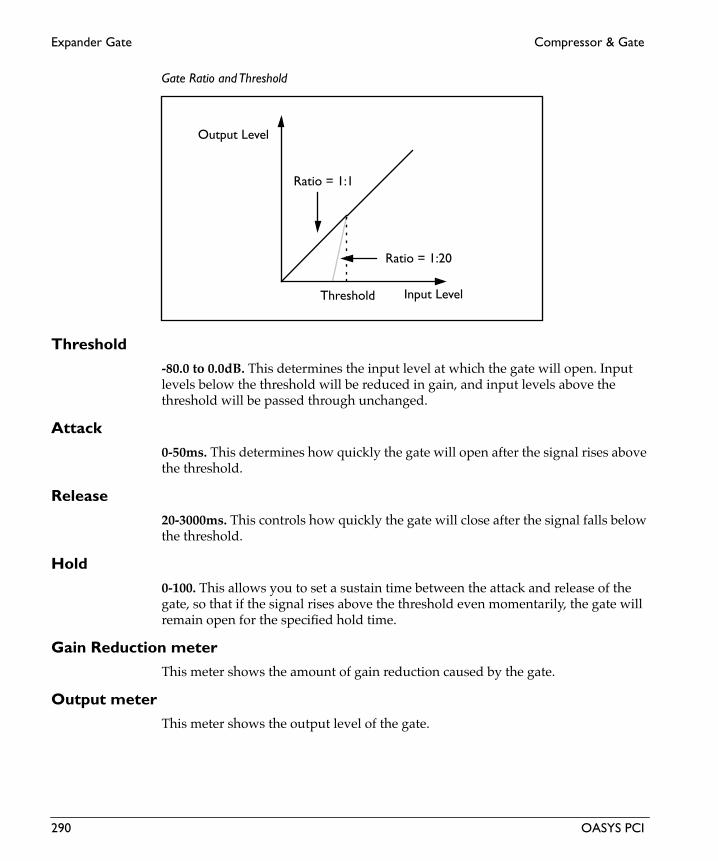
Expander Gate Compressor & Gate
Eng
lish
Gate Ratio and Threshold
Threshold-80.0 to 0.0dB. This determines the input level at which the gate will open. Input levels below the threshold will be reduced in gain, and input levels above the threshold will be passed through unchanged.
Attack0-50ms. This determines how quickly the gate will open after the signal rises above the threshold.
Release20-3000ms. This controls how quickly the gate will close after the signal falls below the threshold.
Hold0-100. This allows you to set a sustain time between the attack and release of the gate, so that if the signal rises above the threshold even momentarily, the gate will remain open for the specified hold time.
Gain Reduction meterThis meter shows the amount of gain reduction caused by the gate.
Output meterThis meter shows the output level of the gate.
Input Level
Output Level
Threshold
Ratio = 1:20
Ratio = 1:1
290 OASYS PCI

Compressor & Gate Expander Gate
Gate Attack and Release
Threshold
Attack = 0.Release = 20
Attack = 50,Release = 500
ReleaseAttack
Dry
Wet
Wet
OASYS PCI 291

Limiter Compressor & Gate
Eng
lish
LimiterThis is a mono-in, mono-out limiter. This effect limits gain to an absolute maximum level, somewhat like a compressor with an infinite ratio. It also features automatic makeup gain with a controllable volume ceiling, and lookahead for eliminating transient overshoot.
Input-INF, -69.0 to 0.0dB. This sets the input level for the limiter.
Input meterThis meter shows the input level. This is particularly helpful when setting the threshold.
Input SelectLeft. Left + Right. The action of the limiter is controlled by the level of the input signal. The Input Select determines whether the limiter will be controlled by the left input only, or by the combination of the left and right signals. Note that this is a mono limiter only; stereo signals will be merged to mono.
Limiter Threshold
Threshold-40.0 to 0.0dB. This determines the input level at which the limiter will start to work. Input levels above the threshold will be limited, and input levels below the threshold will not be affected.
Input Level
Output Level
Threshold
Limited signal(Ratio approx. ∞)
292 OASYS PCI

Compressor & Gate Limiter
Lookahead0.00-3.00ms. The lookahead delays the signal very slightly, allowing the limited to “look ahead” for large volume jumps. This allows better handling of large transients, such as in drums, percussion, bass and guitar, and other sounds with sharp attacks.
Attack1-100ms. This determines how quickly the limiter will take affect after the signal crosses above the threshold.
Release50-4000ms. This controls how quickly the limiter will stop reducing volume level after the signal falls below the threshold.
Ceiling-18 to 0dB. The limiter includes an automatic makeup gain, based on the threshold setting. This sets the target output volume for the makeup gain.
Gain Reduction meterThis meter shows the amount of gain reduction caused by the limiter.
Output meterThis meter shows the output level of the limiter.
OASYS PCI 293

MIDI Gate Compressor & Gate
Eng
lish
MIDI GateThis is a mono-in, mono-out MIDI-controlled gate. Unlike the Expander Gate, which is controlled by the input level, the MIDI Gate opens and closes via a MIDI trigger. You can use this for manually gating a recorded signal, for precise control over the gating process, or for special effects, such as rhythmic gating.
You can also think of this as the “amp envelope” section from an analog synthesizer.
MIDI Gate
Volume0-100. This sets the default volume level for signals passing through the gate. For complete gating, set this to 0. Use low and middle values to create subtle pulsing effects, in which the signal is always present, but triggering the gate makes it louder.
Env Amount0-100. This controls the amount of affect the envelope will have on the output level, adding to the setting on the Volume knob. At 0, the envelope will have no affect. At +100, the envelope will set the output to max at its peak, even if Volume is set to 0.
Envelope amount affect on output volume
Envelope
Attack0-100. This sets the attack time of the amplitude envelope, which controls how long it takes from the moment that the key is pressed until the envelope reaches its peak.
Decay 0-100. This sets the decay time of the amplitude envelope, which controls how long it takes the envelope to fall to the sustain level after the attack is complete.
+100
0
Enve
lope
am
ount
294 OASYS PCI

Compressor & Gate MIDI Gate
Sustain0-100. This sets the sustain level for the amplitude envelope. After the decay time is complete, the envelope will stay at this level as long as the note is held.
Release0-100. This sets the release time of the amplitude envelope, which controls how long it takes the envelope to fall to zero after the note is released.
TriggerList of Modulation Sources. This sets the modulation source for controlling the gate. For a complete list, please see “Modulation Sources” on page 2.
ADSR Envelope
Attack time Decay time Release timeSustain while
SustainLevel
holding note
Enve
lope
Am
ount
OASYS PCI 295

St Compressor Compressor & Gate
Eng
lish
St CompressorThis is a stereo-in, stereo-out compressor. Compressors regulate volume level, and are also often used to give a “punchy” effect to sounds such as guitars, basses, pianos, and drums.
Input-INF, -69.0 to 0.0dB. This sets the input level for the compressor.
Input meterThis meter shows the input level. This is particularly helpful when setting the compression threshold.
Input SelectLeft. Right, Left + Right. The action of the compressor is controlled by the level of the input signal. The Input Select determines whether the compressor will be controlled by the left input only, the right input only, or by the combination of the left and right signals.
Ratio1.00:1-20.00:1. This determines how strong the effect of the compressor will be, expressed in terms of how many dB in input level is required for a 1dB change in output level.
At 1.00:1, the compressor has no effect. At 20.00:1, a 20dB increase in the input level (over the threshold) results in only a 1dB change in output.
Compressor Ratio and Threshold
Input Level
Output Level
Threshold
Ratio = 20:1
Ratio = 1:1
296 OASYS PCI

Compressor & Gate St Compressor
Threshold-40.0 to 0.0dB. This determines the input level at which the compressor will start to work. Input levels above the threshold will be compressed, and input levels below the threshold will not be compressed.
Attack1-100ms. This determines how quickly the compressor will take affect after the signal crosses above the threshold.
Release50-4000ms. This controls how quickly the compressor will stop reducing volume level after the signal falls below the threshold.
Gain0-24dB. This allows you to boost the gain after the compressor. In general, try to set the gain to match the maximum level shown on the gain reduction meter. Setting this too high can cause clipping on the output.
Gain Reduction meterThis meter shows the amount of gain reduction caused by the compressor.
Output meterThis meter shows the output level of the compressor.
OASYS PCI 297

St Expander Gate Compressor & Gate
Eng
lish
St Expander Gate
This is a stereo-input, stereo-output expander and gate. You might think of it as an inverse compressor; when the input falls below the threshold, the output level is reduced. This allows you to mute low-level sounds to clean up a recording with background noise, and can also be used for creative effects, such as gated reverbs.
Input-INF, -69.0 to 0.0dB. This sets the input level for the gate.
Input meterThis meter shows the input level. This is particularly helpful when setting the gate threshold.
Input SelectLeft. Right, Left + Right. The action of the gate is controlled by the level of the input signal. The Input Select determines whether the gate will be controlled by the left input only, the right input only, or by the combination of the left and right signals.
Ratio1:1.00-1:128.00. This determines how strong the effect of the gate will be, expressed in terms of how many dB the output level will be reduced for each 1dB the input signal falls below the threshold. Use lower settings for gentle expansion, and set it to the maximum value for true gating.
At 1:1.00, the gate has no effect. At 1:10.00, the output gain is reduced 10dB for each 1dB the signal falls below the threshold, creating 10-to-1 expansion. At 1:128.00, when the input signal falls 1dB below the threshold, the output level will be reduced by 128dB, creating a full gate.
298 OASYS PCI

Compressor & Gate St Expander Gate
Gate Ratio and Threshold
Threshold-80.0 to 0.0dB. This determines the input level at which the gate will open. Input levels below the threshold will be reduced in gain, and input levels above the threshold will be passed through unchanged.
Attack0-50ms. This determines how quickly the gate will open after the signal rises above the threshold.
Release20-3000ms. This controls how quickly the gate will close after the signal falls below the threshold.
Hold0-100. This allows you to set a sustain time between the attack and release of the gate, so that if the signal rises above the threshold even momentarily, the gate will remain open for the specified hold time.
Gain Reduction meterThis meter shows the amount of gain reduction caused by the gate.
Output meterThis meter shows the output level of the gate.
Input Level
Output Level
Threshold
Ratio = 1:20
Ratio = 1:1
OASYS PCI 299

St Expander Gate Compressor & Gate
Eng
lish
Gate Attack and Release
Threshold
Attack = 0.Release = 20
Attack = 50,Release = 500
ReleaseAttack
Dry
Wet
Wet
300 OASYS PCI

Compressor & Gate St Limiter
St LimiterThis is a stereo-in, stereo-out limiter. This effect limits gain to an absolute maximum volume level, somewhat like a compressor with an infinite ratio. It also features automatic makeup gain with a controllable volume ceiling, and lookahead for eliminating transient overshoot.
Input-INF, -69.0 to 0.0dB. This sets the input level for the limiter.
Input meterThis meter shows the input level. This is particularly helpful when setting the threshold.
Input SelectLeft. Right, Left + Right. The action of the limiter is controlled by the level of the input signal. The Input Select determines whether the limiter will be controlled by the left input only, the right input only, or by the combination of the left and right signals.
Limiter Threshold
Threshold-40.0 to 0.0dB. This determines the input level at which the limiter will start to work. Input levels above the threshold will be limited, and input levels below the threshold will not be affected.
Input Level
Output Level
Threshold
Limited signal(Ratio approx. ∞)
OASYS PCI 301

St Limiter Compressor & Gate
Eng
lish
Lookahead0.00-3.00ms. The lookahead delays the signal very slightly, allowing the limited to “look ahead” for large volume jumps. This allows better handling of large transients, such as in drums, percussion, bass and guitar, and other sounds with sharp attacks.
Attack1-100ms. This determines how quickly the limiter will take affect after the signal crosses above the threshold.
Release50-4000ms. This controls how quickly the limiter will stop reducing volume level after the signal falls below the threshold.
Ceiling-18 to 0dB. The limiter includes an automatic makeup gain, based on the threshold setting. This sets the target output volume for the makeup gain.
Gain Reduction meterThis meter shows the amount of gain reduction caused by the limiter.
Output meterThis meter shows the output level of the limiter.
302 OASYS PCI

Delay

3Tap Delay A Delay
Eng
lish
3Tap Delay AThis is a three-tap multitap delay, with separate level, pan, feedback amount, and high and low filters for each tap. The delay length can be set either in milliseconds or by tempo and note value.
Input
SourceLeft, L + R. This is a mono-in, stereo-out effect. Stereo signals are preserved in the dry mix at the output, but the effect itself has only a single, mono input.
When this is set to Left, only the left channel will be routed into the effect.
When this is set to L + R, the left and right channels will be summed together, and then routed into the effect.
Level-INF, -69.0 to 0.0dB. This sets the input level for the effect. It does not affect the dry signal.
Level ModList of Modulation Sources. This sets the modulation source for controlling the input level, for “splashed” delays. For a complete list, please see “Modulation Sources” on page 2.
Mod Amount+/-100. This sets the amount by which the mod source affects the input level.
Delay Mode
Delay ModeDelay Time, Manual Tempo. This determines how the delay times will be controlled.
Delay Time. The delay times will be controlled by the tap’s Delay Time knobs.
Manual Tempo. The delay times will be controlled by the combination of the Manual Tempo knob and each tap’s Note Value menu.
Manual Tempo40-240bpm. This sets the tempo for the delays, when the Delay Mode is set to Manual Tempo.
Taps 1-3Each of the three taps has the same features.
304 OASYS PCI

Delay 3Tap Delay A
Delay Time0.0-2000.0ms. This sets the delay time for the tap, in milliseconds.
This parameter only applies when the Delay Mode is set to Delay Time. When Delay Mode is set to Tempo, this has no effect.
Note Value1/32, 1/32 dotted, 1/16, 1/16 dotted, 1/16 triplet, 1/8, 1/8 dotted, 1/8 triplet, 1/4, 1/4 dotted, 1/4 triplet, 1/2, 1/2 dotted, 1/2 triplet, 1 bar, 2 bars. This sets the length of the tap’s delay, in note value.
This parameter only applies when the Delay Mode is set to Tempo. When Delay Mode is set to Delay Time, the Note Value has no effect.
Fine Adjust+/-10%. This adjusts the tap’s delay time as a percentage of the time set with either the Delay Time or Note Value parameters. You can use this to create swing rhythms, for instance.
Level0-100. This sets the volume level of the tap.
Invert PhaseOn, Off. This adjusts the phase of the tap’s output. You can use this to create different tonal qualities as the delays overlap with each other, or with the main signal.
Pan+/-100. This controls the stereo pan of the tap’s output.
Feedback0-100. This adjusts the amount of feedback from the tap back into the delay line.
Invert PhaseOn, Off. This controls the phase of the feedback. You can use this to adjust the tonal quality of the delay, as it overlaps with other delays or with the main signal.
Low Cut24-24000Hz. This filter cuts the tap’s low frequencies. Use this to make the delay sound thinner.
High Cut24-24000Hz. This filter cuts the tap’s high frequencies. Use this to make the delay sound warmer, like a tape delay.
OASYS PCI 305

3Tap Delay A Delay
Eng
lish
Feedback Modulation
Feedback ModList of Modulation Sources. This sets the modulation source for controlling the delay feedback levels, affecting all three taps equally. For a complete list, please see “Modulation Sources” on page 2.
Mod Amount+/-100. This sets the amount by which the mod source affects the feedback level.
Output
Wet/DryDry, 1:99-99:1, Wet. This sets the balance between the effect and the dry signal.
Wet/Dry ModList of Modulation Sources. This sets the modulation source for controlling the wet/dry mix. For a complete list, please see “Modulation Sources” on page 2.
Mod Amount+/-100. This sets the amount by which the mod source affects the wet/dry mix.
306 OASYS PCI

Delay 3Tap MidiDly
3Tap MidiDlyThis is a three-tap multitap delay with smooth, clickless MIDI clock synchronization. You can also modulate the delay times smoothly via MIDI controllers. Each tap has its own level, pan, feedback amount, and high and low filters.
Input
SourceLeft, L + R. This is a mono-in, stereo-out effect. Stereo signals are preserved in the dry mix at the output, but the effect itself has only a single, mono input.
When this is set to Left, only the left channel will be routed into the effect.
When this is set to L + R, the left and right channels will be summed together, and then routed into the effect.
Level-INF, -69.0 to 0.0dB. This sets the input level for the effect. It does not affect the dry signal.
Level ModList of Modulation Sources. This sets the modulation source for controlling the input level, for “splashed” delays. For a complete list, please see “Modulation Sources” on page 2.
Mod Amount+/-100. This sets the amount by which the mod source affects the input level.
Delay Mode
Delay ModeDelay Time, Manual Tempo, MIDI Tempo. This determines how the delay times will be controlled.
Delay Time. The delay times will be controlled by the tap’s Delay Time knobs.
Manual Tempo. The delay times will be controlled by the combination of the Manual Tempo knob and each tap’s Note Value menu.
MIDI Tempo. The delay times will be controlled by the combination of received MIDI clocks and each tap’s Note Value menu.
Manual Tempo40-240bpm. This sets the tempo for the delays, when the Delay Mode is set to Manual Tempo.
OASYS PCI 307

3Tap MidiDly Delay
Eng
lish
Taps 1-3Each of the three taps has the same features.
Delay Time0.0-8000.0ms. This sets the delay time for the tap, in milliseconds.
This parameter only applies when the Delay Mode is set to Delay Time. When Delay Mode is set to Tempo, this has no effect.
Note Value1/32, 1/32 dotted, 1/16, 1/16 dotted, 1/16 triplet, 1/8, 1/8 dotted, 1/8 triplet, 1/4, 1/4 dotted, 1/4 triplet, 1/2, 1/2 dotted, 1/2 triplet, 1 bar, 2 bars. This sets the length of the tap’s delay, in note value.
This parameter only applies when the Delay Mode is set to Tempo. When Delay Mode is set to Delay Time, the Note Value has no effect.
Fine Adjust+/-10%. This adjusts the tap’s delay time as a percentage of the time set with either the Delay Time or Note Value parameters. You can use this to create swing rhythms, for instance.
Level0-100. This sets the volume level of the tap.
Invert PhaseOn, Off. This adjusts the phase of the tap’s output. You can use this to create different tonal qualities as the delays overlap with each other, or with the main signal.
Pan+/-100. This controls the stereo pan of the tap’s output.
Feedback0-100. This adjusts the amount of feedback from the tap back into the delay line.
Invert PhaseOn, Off. This controls the phase of the feedback. You can use this to adjust the tonal quality of the delay, as it overlaps with other delays or with the main signal.
Low Cut24-24000Hz. This filter cuts the tap’s low frequencies. Use this to make the delay sound thinner.
308 OASYS PCI

Delay 3Tap MidiDly
High Cut24-24000Hz. This filter cuts the tap’s high frequencies. Use this to make the delay sound warmer, like a tape delay.
Feedback Modulation
Feedback ModList of Modulation Sources. This sets the modulation source for controlling the delay feedback levels, affecting all three taps equally. For a complete list, please see “Modulation Sources” on page 2.
Mod Amount+/-100. This sets the amount by which the mod source affects the feedback level.
Output
Wet/DryDry, 1:99-99:1, Wet. This sets the balance between the effect and the dry signal.
Wet/Dry ModList of Modulation Sources. This sets the modulation source for controlling the wet/dry mix. For a complete list, please see “Modulation Sources” on page 2.
Mod Amount+/-100. This sets the amount by which the mod source affects the wet/dry mix.
Delay
Smoothing0.0-100.0. This determines how long it takes for the delay times to respond to tempo changes and MIDI controller modulation. 50.0 works well in most cases. Lower settings will mean that the delay times will change very quickly, but may also cause clicking. Higher settings will make the delays slide very slowly to their new values, which can create interesting special effects.
OASYS PCI 309

40Sec MidiDly Delay
Eng
lish
40Sec MidiDlyThis is a three-tap multitap delay with smooth, clickless MIDI clock synchronization, and a maximum delay time of 40 seconds. You can also modulate the delay times smoothly via MIDI controllers. Each tap has its own level, pan, feedback amount, and high and low filters.
Input
SourceLeft, L + R. This is a mono-in, stereo-out effect. Stereo signals are preserved in the dry mix at the output, but the effect itself has only a single, mono input.
When this is set to Left, only the left channel will be routed into the effect.
When this is set to L + R, the left and right channels will be summed together, and then routed into the effect.
Level-INF, -69.0 to 0.0dB. This sets the input level for the effect. It does not affect the dry signal.
Level ModList of Modulation Sources. This sets the modulation source for controlling the input level, for “splashed” delays. For a complete list, please see “Modulation Sources” on page 2.
Mod Amount+/-100. This sets the amount by which the mod source affects the input level.
Delay Mode
Delay ModeDelay Time, Manual Tempo, MIDI Tempo. This determines how the delay times will be controlled.
Delay Time. The delay times will be controlled by the tap’s Delay Time knobs.
Manual Tempo. The delay times will be controlled by the combination of the Manual Tempo knob and each tap’s Note Value menu.
MIDI Tempo. The delay times will be controlled by the combination of received MIDI clocks and each tap’s Note Value menu.
Manual Tempo40-240bpm. This sets the tempo for the delays, when the Delay Mode is set to Manual Tempo.
310 OASYS PCI

Delay 40Sec MidiDly
Taps 1-3Each of the three taps has the same features.
Delay Time0.0-40000.0ms. This sets the delay time for the tap, in milliseconds.
This parameter only applies when the Delay Mode is set to Delay Time. When Delay Mode is set to Tempo, this has no effect.
Note Value1/32, 1/32 dotted, 1/16, 1/16 dotted, 1/16 triplet, 1/8, 1/8 dotted, 1/8 triplet, 1/4, 1/4 dotted, 1/4 triplet, 1/2, 1/2 dotted, 1/2 triplet, 1 bar, 2 bars. This sets the length of the tap’s delay, in note value.
This parameter only applies when the Delay Mode is set to Tempo. When Delay Mode is set to Delay Time, the Note Value has no effect.
Fine Adjust+/-10%. This adjusts the tap’s delay time as a percentage of the time set with either the Delay Time or Note Value parameters. You can use this to create swing rhythms, for instance.
Level0-100. This sets the volume level of the tap.
Invert PhaseOn, Off. This adjusts the phase of the tap’s output. You can use this to create different tonal qualities as the delays overlap with each other, or with the main signal.
Pan+/-100. This controls the stereo pan of the tap’s output.
Feedback0-100. This adjusts the amount of feedback from the tap back into the delay line.
Invert PhaseOn, Off. This controls the phase of the feedback. You can use this to adjust the tonal quality of the delay, as it overlaps with other delays or with the main signal.
Low Cut24-24000Hz. This filter cuts the tap’s low frequencies. Use this to make the delay sound thinner.
OASYS PCI 311

40Sec MidiDly Delay
Eng
lish
High Cut24-24000Hz. This filter cuts the tap’s high frequencies. Use this to make the delay sound warmer, like a tape delay.
Feedback Modulation
Feedback ModList of Modulation Sources. This sets the modulation source for controlling the delay feedback levels, affecting all three taps equally. For a complete list, please see “Modulation Sources” on page 2.
Mod Amount+/-100. This sets the amount by which the mod source affects the feedback level.
Output
Wet/DryDry, 1:99-99:1, Wet. This sets the balance between the effect and the dry signal.
Wet/Dry ModList of Modulation Sources. This sets the modulation source for controlling the wet/dry mix. For a complete list, please see “Modulation Sources” on page 2.
Mod Amount+/-100. This sets the amount by which the mod source affects the wet/dry mix.
Delay
Smoothing0.0-100.0. This determines how long it takes for the delay times to respond to tempo changes and MIDI controller modulation. 50.0 works well in most cases. Lower settings will mean that the delay times will change very quickly, but may also cause clicking. Higher settings will make the delays slide very slowly to their new values, which can create interesting special effects.
312 OASYS PCI

Delay Delay Mod Long
Delay Mod LongThis is an 8-second version of Delay Mod (described on page 315), featuring smoothly modulatable delay time and high and low filters.
Input
SourceLeft, L + R. This is a mono-in, mono-out effect. Stereo signals are preserved in the dry mix at the output, but the effect itself has only a single, mono input.
When this is set to Left, only the left channel will be routed into the effect.
When this is set to L + R, the left and right channels will be summed together, and then routed into the effect.
Level-INF, -69.0 to 0.0dB. This sets the input level for the effect. It does not affect the dry signal.
Level ModList of Modulation Sources. This sets the modulation source for controlling the input level, for “splashed” delays. For a complete list, please see “Modulation Sources” on page 2.
Mod Amount+/-100. This sets the amount by which the mod source affects the input level.
Delay
Delay Time0.0-8000.0ms. This sets the delay time for the tap, in milliseconds.
Delay ModList of Modulation Sources. This sets the modulation source for controlling the delay time. For a complete list, please see “Modulation Sources” on page 2.
Mod Amount+/-100. This sets the amount by which the mod source affects the delay time.
Feedback
Feedback+/-100. This adjusts the amount of feedback from the tap back into the delay line. Negative values invert the phase of the feedback.
OASYS PCI 313

Delay Mod Long Delay
Eng
lish
Feedback ModList of Modulation Sources. This sets the modulation source for controlling the delay feedback levels, affecting all three taps equally. For a complete list, please see “Modulation Sources” on page 2.
Mod Amount+/-100. This sets the amount by which the mod source affects the feedback level.
Damping
High0-100. This filter cuts the delay’s high frequencies. Use this to make the delay sound warmer, like a tape delay.
Low0-100. This filter cuts the delay’s low frequencies. Use this to make the delay sound thinner.
Output
ModeMono, Stereo. This controls whether the effect output is mono or simulated stereo.
When this is set to Mono, the output is in mono.
When this is set to Stereo, the output is simulated stereo, with the right effect output inverted. Note that this simulated stereo effect is not mono-compatible.
Wet/DryDry, 1:99-99:1, Wet. This sets the balance between the effect and the dry signal.
Wet/Dry ModList of Modulation Sources. This sets the modulation source for controlling the wet/dry mix. For a complete list, please see “Modulation Sources” on page 2.
Mod Amount+/-100. This sets the amount by which the mod source affects the wet/dry mix.
314 OASYS PCI

Delay Delay Mod
Delay ModThis is a delay with smoothly modulatable delay time and high and low filters. For a longer version of the same delay, see “Delay Mod Long” on page 313.
Input
SourceLeft, L + R. This is a mono-in, mono-out effect. Stereo signals are preserved in the dry mix at the output, but the effect itself has only a single, mono input.
When this is set to Left, only the left channel will be routed into the effect.
When this is set to L + R, the left and right channels will be summed together, and then routed into the effect.
Level-INF, -69.0 to 0.0dB. This sets the input level for the effect. It does not affect the dry signal.
Level ModList of Modulation Sources. This sets the modulation source for controlling the input level, for “splashed” delays. For a complete list, please see “Modulation Sources” on page 2.
Mod Amount+/-100. This sets the amount by which the mod source affects the input level.
Delay
Delay Time0.0-680.0ms. This sets the delay time, in milliseconds.
Delay ModList of Modulation Sources. This sets the modulation source for controlling the delay time. For a complete list, please see “Modulation Sources” on page 2.
Mod Amount+/-100. This sets the amount by which the mod source affects the delay time.
Feedback
Feedback+/-100. This adjusts the amount of feedback into the delay line. Negative values invert the phase of the feedback.
OASYS PCI 315

Delay Mod Delay
Eng
lish
Feedback ModList of Modulation Sources. This sets the modulation source for controlling the delay feedback level. For a complete list, please see “Modulation Sources” on page 2.
Mod Amount+/-100. This sets the amount by which the mod source affects the feedback level.
Damping
High0-100. This filter cuts the delay’s high frequencies. Use this to make the delay sound warmer, like a tape delay.
Low0-100. This filter cuts the delay’s low frequencies. Use this to make the delay sound thinner.
Output
ModeMono, Stereo. This controls whether the effect output is mono or simulated stereo.
When this is set to Mono, the output is in mono.
When this is set to Stereo, the output is simulated stereo, with the right effect output inverted. Note that this simulated stereo effect is not mono-compatible.
Wet/DryDry, 1:99-99:1, Wet. This sets the balance between the effect and the dry signal.
Wet/Dry ModList of Modulation Sources. This sets the modulation source for controlling the wet/dry mix. For a complete list, please see “Modulation Sources” on page 2.
Mod Amount+/-100. This sets the amount by which the mod source affects the wet/dry mix.
316 OASYS PCI

Delay Delay
DelayThis is a simple delay with high and low filters.
Input
SourceLeft, L + R. This is a mono-in, mono-out effect. Stereo signals are preserved in the dry mix at the output, but the effect itself has only a single, mono input.
When this is set to Left, only the left channel will be routed into the effect.
When this is set to L + R, the left and right channels will be summed together, and then routed into the effect.
Level-INF, -69.0 to 0.0dB. This sets the input level for the effect. It does not affect the dry signal.
Level ModList of Modulation Sources. This sets the modulation source for controlling the input level, for “splashed” delays. For a complete list, please see “Modulation Sources” on page 2.
Mod Amount+/-100. This sets the amount by which the mod source affects the input level.
Delay
Delay Time0.0-680.0ms. This sets the delay time for the tap, in milliseconds.
Feedback
Feedback+/-100. This adjusts the amount of feedback from the tap back into the delay line. Negative values invert the phase of the feedback.
Feedback ModList of Modulation Sources. This sets the modulation source for controlling the delay feedback levels, affecting all three taps equally. For a complete list, please see “Modulation Sources” on page 2.
Mod Amount+/-100. This sets the amount by which the mod source affects the feedback level.
OASYS PCI 317

Delay Delay
Eng
lish
Damping
High0-100. This filter cuts the delay’s high frequencies. Use this to make the delay sound warmer, like a tape delay.
Low0-100. This filter cuts the delay’s low frequencies. Use this to make the delay sound thinner.
Output
ModeMono, Stereo. This controls whether the effect output is mono or simulated stereo.
When this is set to Mono, the output is in mono.
When this is set to Stereo, the output is simulated stereo, with the right effect output inverted. Note that this simulated stereo effect is not mono-compatible.
Wet/DryDry, 1:99-99:1, Wet. This sets the balance between the effect and the dry signal.
Wet/Dry ModList of Modulation Sources. This sets the modulation source for controlling the wet/dry mix. For a complete list, please see “Modulation Sources” on page 2.
Mod Amount+/-100. This sets the amount by which the mod source affects the wet/dry mix.
318 OASYS PCI

Delay Diffuse Delay
Diffuse DelayThis is a two-tap multitap delay with dual input diffusers. The diffusers are based on part of the O-Verb reverb, and serve to soften and blur the delayed sound. The delays also feature smooth, clickless MIDI clock synchronization, and individual level, pan, feedback amount, and high and low filters per tap.
Input
SourceLeft, L + R. This is a mono-in, stereo-out effect. Stereo signals are preserved in the dry mix at the output, but the effect itself has only a single, mono input.
When this is set to Left, only the left channel will be routed into the effect.
When this is set to L + R, the left and right channels will be summed together, and then routed into the effect.
Level-INF, -69.0 to 0.0dB. This sets the input level for the effect. It does not affect the dry signal.
Diffusion 10.00-100.00. This sets the amount of diffusion in the first diffuser. Setting both diffusers to around 50 produces optimal amounts of diffusion; extremely high levels may cause ringing.
Diffusion 20.00-100.00. This sets the amount of diffusion in the second diffuser.
Delay Control
Delay ModeDelay Time, Manual Tempo, MIDI Tempo. This determines how the delay times will be controlled.
Delay Time. The delay times will be controlled by the tap’s Delay Time knobs.
Manual Tempo. The delay times will be controlled by the combination of the Manual Tempo knob and each tap’s Note Value menu.
MIDI Tempo. The delay times will be controlled by the combination of received MIDI clocks and each tap’s Note Value menu.
Manual Tempo40-240bpm. This sets the tempo for the delays, when the Delay Mode is set to Manual Tempo.
OASYS PCI 319

Diffuse Delay Delay
Eng
lish
Smoothing0.0-100.0. This determines how long it takes for the delay times to respond to tempo changes and MIDI controller modulation. 50.0 works well in most cases. Lower settings will mean that the delay times will change very quickly, but may also cause clicking. Higher settings will make the delays slide very slowly to their new values, which can create interesting special effects.
Delay 1 and Delay 2Both delays have the same features.
Delay Time0.0-8000.0ms. This sets the delay time for the tap, in milliseconds.
This parameter only applies when the Delay Mode is set to Delay Time. When Delay Mode is set to Tempo, this has no effect.
Note Value1/32, 1/32 dotted, 1/16, 1/16 dotted, 1/16 triplet, 1/8, 1/8 dotted, 1/8 triplet, 1/4, 1/4 dotted, 1/4 triplet, 1/2, 1/2 dotted, 1/2 triplet, 1 bar, 2 bars. This sets the length of the tap’s delay, in note value.
This parameter only applies when the Delay Mode is set to Tempo. When Delay Mode is set to Delay Time, the Note Value has no effect.
Fine Adjust+/-10%. This adjusts the tap’s delay time as a percentage of the time set with either the Delay Time or Note Value parameters. You can use this to create swing rhythms, for instance.
Level0-100. This sets the volume level of the tap.
Invert PhaseOn, Off. This inverts the phase of the tap’s output. You can use this to create different tonal qualities as the delays overlap with each other, or with the main signal.
Pan+/-100. This controls the stereo pan of the tap’s output.
Feedback0-100. This adjusts the amount of feedback from the tap back into the delay line.
320 OASYS PCI

Delay Diffuse Delay
Invert PhaseOn, Off. This controls the phase of the feedback. You can use this to adjust the tonal quality of the delay, as it overlaps with other delays or with the main signal.
Low Cut24-24000Hz. This filter cuts the tap’s low frequencies. Use this to make the delay sound thinner.
High Cut24-24000Hz. This filter cuts the tap’s high frequencies. Use this to make the delay sound warmer, like a tape delay.
Feedback
Feedback ModList of Modulation Sources. This sets the modulation source for controlling the delay feedback levels, affecting both delays equally. For a complete list, please see “Modulation Sources” on page 2.
Mod Amount+/-100. This sets the amount by which the mod source affects the feedback level.
Diffusion in feedbackOn, Off. This controls whether the feedback will go through the diffusers or not.
On. The feedback signal will pass through the diffusers. As the feedback continues, it will become increasingly diffuse.
Off. The feedback signal will not go through the diffusers, and so it will remain at the same level of diffusion as the main delays.
Output
Direct Diffusion0-100. This allows you to add in the sound of the diffusers alone, before the delays.
Rolloff0-24000Hz. This controls an overall lowpass filter on the output of the delays. Settings around 6-8kHz are good for producing a warm, smooth sound.
Wet/DryDry, 1:99-99:1, Wet. This sets the balance between the effect and the dry signal.
Wet/Dry ModList of Modulation Sources. This sets the modulation source for controlling the wet/dry mix. For a complete list, please see “Modulation Sources” on page 2.
OASYS PCI 321
Diffuse Delay Delay
Eng
lish
Mod Amount+/-100. This sets the amount by which the mod source affects the wet/dry mix.
322 OASYS PCI

Delay Dual Delay
Dual DelayThis is a true stereo delay with high and low filters, and separate controls for the left and right channels.
Input
Level (Left and Right)-INF, -69.0 to 0.0dB. This sets the input level for the left and right delays. It does not affect the dry signal.
Level ModList of Modulation Sources. This sets the modulation source for controlling the input level, for “splashed” delays. For a complete list, please see “Modulation Sources” on page 2.
Mod Amt (Left and Right)+/-100. This sets the amount by which the mod source affects the left and right delay input levels.
Delays
Delay Time (Left and Right)0.0-680.0ms. This sets the delay times for left and right, in milliseconds.
High Damping (Left and Right)0-100. This filter cuts the left and right delay’s high frequencies. Use this to make the delay sound warmer, like a tape delay.
Low Damping (Left and Right)0-100. This filter cuts the left and right delay’s low frequencies. Use this to make the delay sound thinner.
Feedback
Level (Left and Right)+/-100. This adjusts the amount of feedback for the left and right delays. Negative values invert the phase of the feedback.
Feedback ModList of Modulation Sources. This sets the modulation source for controlling the delay feedback levels, affecting all three taps equally. For a complete list, please see “Modulation Sources” on page 2.
OASYS PCI 323

Dual Delay Delay
Eng
lish
Mod Amt (Left and Right)+/-100. This sets the amount by which the mod source affects the left and right feedback levels.
Output
Wet/Dry (Left and Right)Dry, 1:99-99:1, Wet. This sets the balance between the effect and the dry signal for the left and right channels.
Wet/Dry ModList of Modulation Sources. This sets the modulation source for controlling the wet/dry mix. For a complete list, please see “Modulation Sources” on page 2.
Mod Amt (Left and Right)+/-100. This sets the amount by which the mod source affects the wet/dry mix for the left and right channels.
324 OASYS PCI
Delay L-C-R Delay
L-C-R DelayThis is a three-tap delay with preset panning for the three taps, stereo width control, and high and low filters.
For a longer version of the same delay, see “L-C-R Dly Long” on page 328.
Input
SourceLeft, L + R. This is a mono-in, stereo-out effect. Stereo signals are preserved in the dry mix at the output, but the effect itself has only a single, mono input.
When this is set to Left, only the left channel will be routed into the effect.
When this is set to L + R, the left and right channels will be summed together, and then routed into the effect.
Level-INF, -69.0 to 0.0dB. This sets the input level for the effect. It does not affect the dry signal.
Level ModList of Modulation Sources. This sets the modulation source for controlling the input level, for “splashed” delays. For a complete list, please see “Modulation Sources” on page 2.
Mod Amount+/-100. This sets the amount by which the mod source affects the input level.
Delay Times
Left0.0-680.0ms. This sets the delay time for the left delay, in milliseconds.
Center0.0-680.0ms. This sets the delay time for the center delay, in milliseconds.
Right0.0-680.0ms. This sets the delay time for the right delay, in milliseconds.
Levels
Left-INF, -69.0 to 0.0dB. This sets the output level for the left delay.
OASYS PCI 325

L-C-R Delay Delay
Eng
lish
Center-INF, -69.0 to 0.0dB. This sets the output level for the center delay.
Right-INF, -69.0 to 0.0dB. This sets the output level for the right delay.
Center FeedbackThis section controls the feedback for the center delay.
Feedback+/-100. This adjusts the amount of feedback from the tap back into the delay line. Negative values invert the phase of the feedback.
Feedback ModList of Modulation Sources. This sets the modulation source for controlling the delay feedback levels, affecting all three taps equally. For a complete list, please see “Modulation Sources” on page 2.
Mod Amount+/-100. This sets the amount by which the mod source affects the feedback level.
Damping
PositionPre Delay, Feedback Loop. This controls the position of the filters within the delay effect.
Pre Delay. The damping filters are applied on input only.
Feedback Loop. The feedback goes through the damping filters, so that the feedback becomes increasingly filtered.
High0-100. This filter cuts the delay’s high frequencies. Use this to make the delay sound warmer, like a tape delay.
Low0-100. This filter cuts the delay’s low frequencies. Use this to make the delay sound thinner.
Stereo Spread
Spread+/-100. This controls the width of the stereo image. Negative values will flip the stereo placement.
326 OASYS PCI
Delay L-C-R Delay
Spread ModList of Modulation Sources. This sets the modulation source for controlling the stereo spread. For a complete list, please see “Modulation Sources” on page 2.
Mod Amount+/-100. This sets the amount by which the mod source affects the stereo spread.
Output
Wet/DryDry, 1:99-99:1, Wet. This sets the balance between the effect and the dry signal.
Wet/Dry ModList of Modulation Sources. This sets the modulation source for controlling the wet/dry mix. For a complete list, please see “Modulation Sources” on page 2.
Mod Amount+/-100. This sets the amount by which the mod source affects the wet/dry mix.
OASYS PCI 327

L-C-R Dly Long Delay
Eng
lish
L-C-R Dly LongThis is a longer version of L-C-R Delay (described on page 325), featuring preset panning for the three taps, stereo width control, and high and low filters.
Input
SourceLeft, L + R. This is a mono-in, stereo-out effect. Stereo signals are preserved in the dry mix at the output, but the effect itself has only a single, mono input.
When this is set to Left, only the left channel will be routed into the effect.
When this is set to L + R, the left and right channels will be summed together, and then routed into the effect.
Level-INF, -69.0 to 0.0dB. This sets the input level for the effect. It does not affect the dry signal.
Level ModList of Modulation Sources. This sets the modulation source for controlling the input level, for “splashed” delays. For a complete list, please see “Modulation Sources” on page 2.
Mod Amount+/-100. This sets the amount by which the mod source affects the input level.
Delay Times
Left0.0-1360.0ms. This sets the delay time for the left delay, in milliseconds.
Center0.0-1360.0ms. This sets the delay time for the center delay, in milliseconds.
Right0.0-1360.0ms. This sets the delay time for the right delay, in milliseconds.
Levels
Left-INF, -69.0 to 0.0dB. This sets the output level for the left delay.
328 OASYS PCI

Delay L-C-R Dly Long
Center-INF, -69.0 to 0.0dB. This sets the output level for the center delay.
Right-INF, -69.0 to 0.0dB. This sets the output level for the right delay.
Center FeedbackThis section controls the feedback for the center delay.
Feedback+/-100. This adjusts the amount of feedback from the tap back into the delay line. Negative values invert the phase of the feedback.
Feedback ModList of Modulation Sources. This sets the modulation source for controlling the delay feedback levels, affecting all three taps equally. For a complete list, please see “Modulation Sources” on page 2.
Mod Amount+/-100. This sets the amount by which the mod source affects the feedback level.
Damping
PositionPre Delay, Feedback Loop. This controls the position of the filters within the delay effect.
Pre Delay. The damping filters are applied on input only.
Feedback Loop. The feedback goes through the damping filters, so that the feedback becomes increasingly filtered.
High0-100. This filter cuts the delay’s high frequencies. Use this to make the delay sound warmer, like a tape delay.
Low0-100. This filter cuts the delay’s low frequencies. Use this to make the delay sound thinner.
Stereo Spread
Spread+/-100. This controls the width of the stereo image. Negative values will flip the stereo placement.
OASYS PCI 329

L-C-R Dly Long Delay
Eng
lish
Spread ModList of Modulation Sources. This sets the modulation source for controlling the stereo spread. For a complete list, please see “Modulation Sources” on page 2.
Mod Amount+/-100. This sets the amount by which the mod source affects the stereo spread.
Output
Wet/DryDry, 1:99-99:1, Wet. This sets the balance between the effect and the dry signal.
Wet/Dry ModList of Modulation Sources. This sets the modulation source for controlling the wet/dry mix. For a complete list, please see “Modulation Sources” on page 2.
Mod Amount+/-100. This sets the amount by which the mod source affects the wet/dry mix.
330 OASYS PCI

Delay Midi Delay
Midi DelayThis is a single-tap delay with smooth, clickless MIDI clock synchronization, and dedicated high and low filters. You can also modulate the delay times smoothly via MIDI controllers.
Input
SourceLeft, L + R. This is a mono-in, stereo-out effect. Stereo signals are preserved in the dry mix at the output, but the effect itself has only a single, mono input.
When this is set to Left, only the left channel will be routed into the effect.
When this is set to L + R, the left and right channels will be summed together, and then routed into the effect.
Level-INF, -69.0 to 0.0dB. This sets the input level for the effect. It does not affect the dry signal.
Level ModList of Modulation Sources. This sets the modulation source for controlling the input level, for “splashed” delays. For a complete list, please see “Modulation Sources” on page 2.
Mod Amount+/-100. This sets the amount by which the mod source affects the input level.
Delay Mode
Delay ModeDelay Time, Manual Tempo, MIDI Tempo. This determines how the delay times will be controlled.
Delay Time. The delay times will be controlled by the tap’s Delay Time knobs.
Manual Tempo. The delay times will be controlled by the combination of the Manual Tempo knob and each tap’s Note Value menu.
MIDI Tempo. The delay times will be controlled by the combination of received MIDI clocks and each tap’s Note Value menu.
Manual Tempo40-240bpm. This sets the tempo for the delays, when the Delay Mode is set to Manual Tempo.
OASYS PCI 331

Midi Delay Delay
Eng
lish
Delay
Delay Time0.0-8000.0ms. This sets the delay time, in milliseconds.
This parameter only applies when the Delay Mode is set to Delay Time. When Delay Mode is set to Tempo, this has no effect.
Note Value1/32, 1/32 dotted, 1/16, 1/16 dotted, 1/16 triplet, 1/8, 1/8 dotted, 1/8 triplet, 1/4, 1/4 dotted, 1/4 triplet, 1/2, 1/2 dotted, 1/2 triplet, 1 bar, 2 bars. This sets the length of the tap’s delay, in note value.
This parameter only applies when the Delay Mode is set to Tempo. When Delay Mode is set to Delay Time, the Note Value has no effect.
Fine Adjust+/-10%. This adjusts the delay time as a percentage of the time set with either the Delay Time or Note Value parameters. You can use this to create swing rhythms, for instance.
Level0-100. This sets the volume level of the delay.
Invert PhaseOn, Off. This adjusts the phase of the delay’s output. You can use this to create different tonal qualities as the delays overlap with each other, or with the main signal.
Pan+/-100. This controls the stereo pan of the delay’s output.
Feedback0-100. This adjusts the amount of feedback into the delay line.
Invert PhaseOn, Off. This controls the phase of the feedback. You can use this to adjust the tonal quality of the delay, as it overlaps with other delays or with the main signal.
Low Cut24-24000Hz. This filter cuts the delay’s low frequencies. Use this to make the delay sound thinner.
High Cut24-24000Hz. This filter cuts the delay’s high frequencies. Use this to make the delay sound warmer, like a tape delay.
332 OASYS PCI

Delay Midi Delay
Feedback Modulation
Feedback ModList of Modulation Sources. This sets the modulation source for controlling the delay feedback levels. For a complete list, please see “Modulation Sources” on page 2.
Mod Amount+/-100. This sets the amount by which the mod source affects the feedback level.
Output
Wet/DryDry, 1:99-99:1, Wet. This sets the balance between the effect and the dry signal.
Wet/Dry ModList of Modulation Sources. This sets the modulation source for controlling the wet/dry mix. For a complete list, please see “Modulation Sources” on page 2.
Mod Amount+/-100. This sets the amount by which the mod source affects the wet/dry mix.
Delay
Smoothing0.0-100.0. This determines how long it takes for the delay time to respond to tempo changes and MIDI controller modulation. 50.0 works well in most cases. Lower settings will mean that the delay times will change very quickly, but may also cause clicking. Higher settings will make the delays slide very slowly to their new values, which can create interesting special effects.
OASYS PCI 333

Multitap Delay Delay
Eng
lish
Multitap DelayThis is a two-tap, mono-in, mono-out delay with high and low filters.
Input
SourceLeft, L + R. This is a mono-in, mono-out effect. Stereo signals are preserved in the dry mix at the output, but the effect itself has only a single, mono input.
When this is set to Left, only the left channel will be routed into the effect.
When this is set to L + R, the left and right channels will be summed together, and then routed into the effect.
Level-INF, -69.0 to 0.0dB. This sets the input level for the effect. It does not affect the dry signal.
Level ModList of Modulation Sources. This sets the modulation source for controlling the input level, for “splashed” delays. For a complete list, please see “Modulation Sources” on page 2.
Mod Amount+/-100. This sets the amount by which the mod source affects the input level.
Multitap Delay
Delay 10.0-680.0ms. This sets the delay time for the first tap, in milliseconds.
Level 10-100. This sets the output level for the first tap.
Delay 20.0-680.0ms. This sets the delay time for the second tap, in milliseconds.
Level 20-100. This sets the output level for the second tap.
Low Cut0-100. This filter cuts the delay’s low frequencies. Use this to make the delay sound thinner.
334 OASYS PCI

Delay Multitap Delay
High Cut0-100. This filter cuts the delay’s high frequencies. Use this to make the delay sound warmer, like a tape delay.
Feedback
Feedback+/-100. This adjusts the amount of feedback into the delay line. Negative values invert the phase of the feedback.
Feedback ModList of Modulation Sources. This sets the modulation source for controlling the delay feedback level. For a complete list, please see “Modulation Sources” on page 2.
Mod Amount+/-100. This sets the amount by which the mod source affects the feedback level.
Output
ModeMono, Stereo. This controls whether the effect output is mono or simulated stereo.
When this is set to Mono, the output is in mono.
When this is set to Stereo, the output is simulated stereo, with the right effect output inverted. Note that this simulated stereo effect is not mono-compatible.
Wet/DryDry, 1:99-99:1, Wet. This sets the balance between the effect and the dry signal.
Wet/Dry ModList of Modulation Sources. This sets the modulation source for controlling the wet/dry mix. For a complete list, please see “Modulation Sources” on page 2.
Mod Amount+/-100. This sets the amount by which the mod source affects the wet/dry mix.
OASYS PCI 335
St Delay Long Delay
Eng
lish
St Delay LongThis is a four-second version of St Delay (described on page 338), featuring a true stereo delay, with high and low filters.
Input
Level-INF, -69.0 to 0.0dB. This sets the input level for the effect. It does not affect the dry signal.
Level ModList of Modulation Sources. This sets the modulation source for controlling the input level, for “splashed” delays. For a complete list, please see “Modulation Sources” on page 2.
Mod Amount+/-100. This sets the amount by which the mod source affects the input level.
Stereo Delay
ModeStereo, Cross. This determines whether the stereo image of the delays will match the input, or flip the left and right channels.
Stereo. The stereo image of the inputs will be maintained through the delays.
Cross. The stereo image will be flipped for the delayed signals. The left input will feed the right delay, and the right input will feed the left delay.
L Delay0.0-4000.0ms. This sets the delay time for the left channel, in milliseconds.
R Delay0.0-4000.0ms. This sets the delay time for the right channel, in milliseconds.
Feedback
Feedback+/-100. This adjusts the amount of feedback into the delay lines. Negative values invert the phase of the feedback.
336 OASYS PCI

Delay St Delay Long
Feedback ModList of Modulation Sources. This sets the modulation source for controlling the delay feedback level. For a complete list, please see “Modulation Sources” on page 2.
Mod Amount+/-100. This sets the amount by which the mod source affects the feedback level.
Spread
Spread+/-100. This controls the width of the stereo image. Negative values will flip the stereo placement.
Spread ModList of Modulation Sources. This sets the modulation source for controlling the stereo spread. For a complete list, please see “Modulation Sources” on page 2.
Mod Amount+/-100. This sets the amount by which the mod source affects the stereo spread.
Damping
High Damping0-100. This filter cuts the delay’s high frequencies. Use this to make the delay sound warmer, like a tape delay.
Low Damping0-100. This filter cuts the delay’s low frequencies. Use this to make the delay sound thinner.
Output
Wet/DryDry, 1:99-99:1, Wet. This sets the balance between the effect and the dry signal.
Wet/Dry ModList of Modulation Sources. This sets the modulation source for controlling the wet/dry mix. For a complete list, please see “Modulation Sources” on page 2.
Mod Amount+/-100. This sets the amount by which the mod source affects the wet/dry mix.
OASYS PCI 337

St Delay Delay
Eng
lish
St DelayThis is a simple true stereo delay, with high and low filters.
For a longer version of the same delay, see “St Delay Long” on page 336.
Input
Level-INF, -69.0 to 0.0dB. This sets the input level for the effect. It does not affect the dry signal.
Level ModList of Modulation Sources. This sets the modulation source for controlling the input level, for “splashed” delays. For a complete list, please see “Modulation Sources” on page 2.
Mod Amount+/-100. This sets the amount by which the mod source affects the input level.
Stereo Delay
ModeStereo, Cross. This determines whether the stereo image of the delays will match the input, or flip the left and right channels.
Stereo. The stereo image of the inputs will be maintained through the delays.
Cross. The stereo image will be flipped for the delayed signals. The left input will feed the right delay, and the right input will feed the left delay.
L Delay0.0-680.0ms. This sets the delay time for the left channel, in milliseconds.
R Delay0.0-680.0ms. This sets the delay time for the right channel, in milliseconds.
Feedback
Feedback+/-100. This adjusts the amount of feedback into the delay lines. Negative values invert the phase of the feedback.
338 OASYS PCI

Delay St Delay
Feedback ModList of Modulation Sources. This sets the modulation source for controlling the delay feedback level. For a complete list, please see “Modulation Sources” on page 2.
Mod Amount+/-100. This sets the amount by which the mod source affects the feedback level.
Spread
Spread+/-100. This controls the width of the stereo image. Negative values will flip the stereo placement.
Spread ModList of Modulation Sources. This sets the modulation source for controlling the stereo spread. For a complete list, please see “Modulation Sources” on page 2.
Mod Amount+/-100. This sets the amount by which the mod source affects the stereo spread.
Damping
High Damping0-100. This filter cuts the delay’s high frequencies. Use this to make the delay sound warmer, like a tape delay.
Low Damping0-100. This filter cuts the delay’s low frequencies. Use this to make the delay sound thinner.
Output
Wet/DryDry, 1:99-99:1, Wet. This sets the balance between the effect and the dry signal.
Wet/Dry ModList of Modulation Sources. This sets the modulation source for controlling the wet/dry mix. For a complete list, please see “Modulation Sources” on page 2.
Mod Amount+/-100. This sets the amount by which the mod source affects the wet/dry mix.
OASYS PCI 339

St Diffuse Dly Delay
Eng
lish
St Diffuse DlyThis is a true stereo delay with dual input diffusers for each channel. The diffusers are based on part of the O-Verb reverb, and serve to soften and blur the delayed sound. The delays also feature smooth, clickless MIDI clock synchronization, and individual level, pan, feedback amount, and high and low filters for each channel.
Input
Level-INF, -69.0 to 0.0dB. This sets the input level for the effect. It does not affect the dry signal.
Diffusion 10.00-100.00. This sets the amount of diffusion in the first diffuser. Setting both diffusers to around 50 produces optimal amounts of diffusion; extremely high levels may cause ringing.
Diffusion 20.00-100.00. This sets the amount of diffusion in the second diffuser.
Delay Control
Delay ModeDelay Time, Manual Tempo, MIDI Tempo. This determines how the delay times will be controlled.
Delay Time. The delay times will be controlled by the tap’s Delay Time knobs.
Manual Tempo. The delay times will be controlled by the combination of the Manual Tempo knob and each tap’s Note Value menu.
MIDI Tempo. The delay times will be controlled by the combination of received MIDI clocks and each tap’s Note Value menu.
Manual Tempo40-240bpm. This sets the tempo for the delays, when the Delay Mode is set to Manual Tempo.
Smoothing0.0-100.0. This determines how long it takes for the delay times to respond to tempo changes and MIDI controller modulation. 50.0 works well in most cases. Lower settings will mean that the delay times will change very quickly, but may also cause clicking. Higher settings will make the delays slide very slowly to their new values, which can create interesting special effects.
340 OASYS PCI

Delay St Diffuse Dly
Left Delay and Right DelayThe left and right delays have the same features.
Delay Time0.0-8000.0ms. This sets the delay time for the tap, in milliseconds.
This parameter only applies when the Delay Mode is set to Delay Time. When Delay Mode is set to Tempo, this has no effect.
Note Value1/32, 1/32 dotted, 1/16, 1/16 dotted, 1/16 triplet, 1/8, 1/8 dotted, 1/8 triplet, 1/4, 1/4 dotted, 1/4 triplet, 1/2, 1/2 dotted, 1/2 triplet, 1 bar, 2 bars. This sets the length of the tap’s delay, in note value.
This parameter only applies when the Delay Mode is set to Tempo. When Delay Mode is set to Delay Time, the Note Value has no effect.
Fine Adjust+/-10%. This adjusts the tap’s delay time as a percentage of the time set with either the Delay Time or Note Value parameters. You can use this to create swing rhythms, for instance.
Level0-100. This sets the volume level of the tap.
Invert PhaseOn, Off. This adjusts the phase of the tap’s output. You can use this to create different tonal qualities as the delays overlap with each other, or with the main signal.
Pan+/-100. This controls the stereo pan of the tap’s output.
Feedback0-100. This adjusts the amount of feedback from the tap back into the delay line.
Invert PhaseOn, Off. This controls the phase of the feedback. You can use this to adjust the tonal quality of the delay, as it overlaps with other delays or with the main signal.
Low Cut24-24000Hz. This filter cuts the tap’s low frequencies. Use this to make the delay sound thinner.
OASYS PCI 341

St Diffuse Dly Delay
Eng
lish
High Cut24-24000Hz. This filter cuts the tap’s high frequencies. Use this to make the delay sound warmer, like a tape delay.
Stereo LinkOn, Off. This allows you to link the controls of the two channels.
On. The controls for the Left Delay will control the Right Delay as well.
Off. The Left and Right Delays will be controlled separately.
Flip Left/RightOn, Off. This allows you to flip the stereo image of the delayed signals.
On. The pan settings for both channels will be inverted. For instance, if the channel is set to hard left, it will be flipped to hard right; if it is set to 50 (half-right), it will be flipped to -50 (half left).
Off. The pan settings will be as set by the Pan knobs.
Feedback
Feedback ModList of Modulation Sources. This sets the modulation source for controlling the delay feedback levels, affecting both channels equally. For a complete list, please see “Modulation Sources” on page 2.
Mod Amount+/-100. This sets the amount by which the mod source affects the feedback level.
Cross-feedbackOn, Off. This allows you to swap the feedback for the two channels.
On. The left channel will feed back into the right, and the right channel will feed back into the left.
Off. The channels will feed back into themselves, left into left and right into right.
Diffusion in feedbackOn, Off. This controls whether the feedback will go through the diffusers or not.
On. The feedback signal will pass through the diffusers. As the feedback continues, it will become increasingly diffuse.
Off. The feedback signal will not go through the diffusers, and so it will remain at the same level of diffusion as the main delays.
342 OASYS PCI

Delay St Diffuse Dly
Output
Direct Diffusion0-100. This allows you to add in the sound of the diffusers alone, before the delays.
Rolloff0-24000Hz. This controls an overall lowpass filter on the output of the delays. Settings around 6-8kHz are good for producing a warm, smooth sound.
Wet/DryDry, 1:99-99:1, Wet. This sets the balance between the effect and the dry signal.
Wet/Dry ModList of Modulation Sources. This sets the modulation source for controlling the wet/dry mix. For a complete list, please see “Modulation Sources” on page 2.
Mod Amount+/-100. This sets the amount by which the mod source affects the wet/dry mix.
OASYS PCI 343

St Dynamic Dly Delay
Eng
lish
St Dynamic DlyThe output level of this stereo delay is controlled by the input signal level. You can use this as a ducking delay, so that delay is only heard when you play softly (or pause after playing a phrase), or as a gated delay, so that the delay is only heard when you are playing loudly.
Input
Level-INF, -69.0 to 0.0dB. This sets the input level for the effect. It does not affect the dry signal.
Level ModList of Modulation Sources. This sets the modulation source for controlling the input level, for “splashed” delays. For a complete list, please see “Modulation Sources” on page 2.
Mod Amount+/-100. This sets the amount by which the mod source affects the input level.
Control
Envelope SelectL/R Mix, L Only, R Only. The dynamics section is controlled by the level of the input signal. The Envelope Select determines whether the dynamics will be controlled by the left input only, the right input only, or by the combination of the left and right signals.
Polarity+, -. This determines whether the dynamics will act as a ducker, or as a gate.
+. The dynamics will act as a gate. When the Polarity is positive, delay will be heard when the input signal level exceeds the Threshold value.
-. The dynamics will act as a ducker. When the Polarity is negative, delay will be heard when the input signal level is lower than the Threshold value.
Threshold0-100. This sets the threshold for the dynamics.
Attack0-100. This sets the time that it takes for the gate to open, or for the ducker to close.
344 OASYS PCI

Delay St Dynamic Dly
Release0-100. This sets the time that it takes for the gate to close, or for the ducker to open.
Offset Level0-100. This allows the delay output to pass around the dynamics section, so that there is a minimum level of delay even when the dynamics aren’t letting any signal through.
Dynamic Delay
St. Dynamic Delay
L Delay Time0.0-680.0ms. This sets the delay time for the left channel, in milliseconds.
R Delay Time0.0-680.0ms. This sets the delay time for the right channel, in milliseconds.
Feedback+/-100. This adjusts the amount of feedback into the delay lines. Negative values invert the phase of the feedback.
Threshold
AttackRelease
Delay Time
Dry
Envelope
WetPolarity (-)
WetPolarity (+)
(Ducking Dly)
Level
Time
OASYS PCI 345

St Dynamic Dly Delay
Eng
lish
High Cut0-100. This filter cuts the delay’s high frequencies. Use this to make the delay sound warmer, like a tape delay.
Low Cut0-100. This filter cuts the delay’s low frequencies. Use this to make the delay sound thinner.
Spread+/-100. This controls the width of the stereo image. Negative values will flip the stereo placement.
Output
Wet/DryDry, 1:99-99:1, Wet. This sets the balance between the effect and the dry signal.
Wet/Dry ModList of Modulation Sources. This sets the modulation source for controlling the wet/dry mix. For a complete list, please see “Modulation Sources” on page 2.
Mod Amount+/-100. This sets the amount by which the mod source affects the wet/dry mix.
346 OASYS PCI

Delay St Midi Dly
St Midi DlyThis is a true stereo delay with smooth, clickless MIDI clock synchronization. You can also modulate the delay times smoothly via MIDI controllers, The right and left channels each have their own level, pan, feedback amount, and high and low filters.
Input
Level-INF, -69.0 to 0.0dB. This sets the input level for the effect. It does not affect the dry signal.
Delay Control
Delay ModeDelay Time, Manual Tempo, MIDI Tempo. This determines how the delay times will be controlled.
Delay Time. The delay times will be controlled by the tap’s Delay Time knobs.
Manual Tempo. The delay times will be controlled by the combination of the Manual Tempo knob and each tap’s Note Value menu.
MIDI Tempo. The delay times will be controlled by the combination of received MIDI clocks and each tap’s Note Value menu.
Manual Tempo40-240bpm. This sets the tempo for the delays, when the Delay Mode is set to Manual Tempo.
Smoothing0.0-100.0. This determines how long it takes for the delay times to respond to tempo changes and MIDI controller modulation. 50.0 works well in most cases. Lower settings will mean that the delay times will change very quickly, but may also cause clicking. Higher settings will make the delays slide very slowly to their new values, which can create interesting special effects.
Left Delay and Right DelayThe left and right delays have the same features.
Delay Time0.0-8000.0ms. This sets the delay time for the tap, in milliseconds.
This parameter only applies when the Delay Mode is set to Delay Time. When Delay Mode is set to Tempo, this has no effect.
OASYS PCI 347

St Midi Dly Delay
Eng
lish
Note Value1/32, 1/32 dotted, 1/16, 1/16 dotted, 1/16 triplet, 1/8, 1/8 dotted, 1/8 triplet, 1/4, 1/4 dotted, 1/4 triplet, 1/2, 1/2 dotted, 1/2 triplet, 1 bar, 2 bars. This sets the length of the tap’s delay, in note value.
This parameter only applies when the Delay Mode is set to Tempo. When Delay Mode is set to Delay Time, the Note Value has no effect.
Fine Adjust+/-10%. This adjusts the tap’s delay time as a percentage of the time set with either the Delay Time or Note Value parameters. You can use this to create swing rhythms, for instance.
Level0-100. This sets the volume level of the tap.
Invert PhaseOn, Off. This adjusts the phase of the tap’s output. You can use this to create different tonal qualities as the delays overlap with each other, or with the main signal.
Pan+/-100. This controls the stereo pan of the tap’s output.
Feedback0-100. This adjusts the amount of feedback from the tap back into the delay line.
Invert PhaseOn, Off. This controls the phase of the feedback. You can use this to adjust the tonal quality of the delay, as it overlaps with other delays or with the main signal.
Low Cut24-24000Hz. This filter cuts the tap’s low frequencies. Use this to make the delay sound thinner.
High Cut24-24000Hz. This filter cuts the tap’s high frequencies. Use this to make the delay sound warmer, like a tape delay.
Stereo LinkOn, Off. This allows you to link the controls of the two channels.
On. The controls for the Left Delay will control the Right Delay as well.
Off. The Left and Right Delays will be controlled separately.
348 OASYS PCI

Delay St Midi Dly
Flip Left/RightOn, Off. This allows you to flip the stereo image of the delayed signals.
On. The pan settings for both channels will be inverted. For instance, if the channel is set to hard left, it will be flipped to hard right; if it is set to 50 (half-right), it will be flipped to -50 (half left).
Off. The pan settings will be as set by the Pan knobs.
Feedback Modulation
Feedback ModList of Modulation Sources. This sets the modulation source for controlling the delay feedback levels, affecting all three taps equally. For a complete list, please see “Modulation Sources” on page 2.
Mod Amount+/-100. This sets the amount by which the mod source affects the feedback level.
Cross-feedbackOn, Off. This allows you to swap the feedback for the two channels.
On. The left channel will feed back into the right, and the right channel will feed back into the left.
Off. The channels will feed back into themselves, left into left and right into right.
Output
Wet/DryDry, 1:99-99:1, Wet. This sets the balance between the effect and the dry signal.
Wet/Dry ModList of Modulation Sources. This sets the modulation source for controlling the wet/dry mix. For a complete list, please see “Modulation Sources” on page 2.
Mod Amount+/-100. This sets the amount by which the mod source affects the wet/dry mix.
OASYS PCI 349

St Mod Delay Delay
Eng
lish
St Mod DelayThis is a true stereo delay with smoothly modulatable delay time and high and low filters. For a longer version of the same delay, see “Delay Mod Long” on page 313.
Input
Level-INF, -69.0 to 0.0dB. This sets the input level for the effect. It does not affect the dry signal.
Trim ModList of Modulation Sources. This sets the modulation source for controlling the input level, for “splashed” delays. For a complete list, please see “Modulation Sources” on page 2.
Mod Amount+/-100. This sets the amount by which the mod source affects the input level.
Stereo Modulation Delay
ModeLFO, Manual. The mode sets whether the delay will be modulated via the LFO, or via the manual mod source.
L Delay0.0-680.0ms. This sets the delay time for the left channel, in milliseconds.
R Delay0.0-680.0ms. This sets the delay time for the right channel, in milliseconds.
L Depth0-100. This sets the modulation depth for the left delay.
R Depth0-100. This sets the modulation depth for the right delay.
L Feedback+/-100. This adjusts the amount of feedback for the left delay. Negative values invert the phase of the feedback.
R Feedback+/-100. This adjusts the amount of feedback for the right delay. Negative values invert the phase of the feedback.
350 OASYS PCI

Delay St Mod Delay
Damping0-100. This filter cuts the delay’s high frequencies. Use this to make the delay sound warmer, like a tape delay.
LFO
WaveformTriangle, Sine. This selects the shape of the LFO.
Waveforms and Phase
Frequency0.00-20.00Hz. This controls the speed of the LFO.
Shape+/-100. This adjusts the curves of the waveform between logarithmic (-100), linear (0), and exponential (100).
Key SyncOn, Off. This enables and disables resetting the LFO phase using the Key Sync modulator.
Key Sync SourceList of Modulation Sources. This sets the modulation source for resetting the phase of the LFOs. For a complete list, please see “Modulation Sources” on page 2.
L PhaseThis sets the point in the waveform at which the left LFO starts. Whenever the Key Sync controller is received, the LFO will start from this point. See the graphic Waveforms and Phase, above, for more information.
0˚ 90˚ 180˚-90˚-180˚ 0˚ 90˚ 180˚-90˚-180˚
Triangle Sine
OASYS PCI 351

St Mod Delay Delay
Eng
lish
R PhaseThis sets the point in the waveform at which the right LFO starts. Whenever the Key Sync controller is received, the LFO will start from this point. Off-setting the phase between the right and left LFOs enhances the stereo effect.
Manual Mod
Mod SourceList of Modulation Sources. This sets the modulation source for controlling the delay time. For a complete list, please see “Modulation Sources” on page 2.
Response0-100. This sets the rate at which the delay time changes in response to the modulator.
PolarityL/R:+/+. L/R +/-. This allows you to modulate both delay times equally, or to increase the left delay time while decreasing the right delay time.
Output
Wet/DryDry, 1:99-99:1, Wet. This sets the balance between the effect and the dry signal.
Wet/Dry ModList of Modulation Sources. This sets the modulation source for controlling the wet/dry mix. For a complete list, please see “Modulation Sources” on page 2.
Mod Amount+/-100. This sets the amount by which the mod source affects the wet/dry mix.
Invert Wet PhaseOn, Off. This allows you to invert the phase of the delay output.
352 OASYS PCI

Delay St Multitap Dly
St Multitap DlyThis is a two-tap, true stereo delay with high and low filters, and a selection of feedback paths.
Input
Level-INF, -69.0 to 0.0dB. This sets the input level for the effect. It does not affect the dry signal.
Level ModList of Modulation Sources. This sets the modulation source for controlling the input level, for “splashed” delays. For a complete list, please see “Modulation Sources” on page 2.
Mod Amount+/-100. This sets the amount by which the mod source affects the input level.
Stereo Multitap Delay
ModeNormal, Cross Feedback, Cross Pan 1, Cross Pan 2. This sets the way that the input goes through the delays, and the direction of the feedback paths, as shown below.
Feedback Modes
Normal Cross Feedback
Cross Pan 2Cross Pan 1
OASYS PCI 353

St Multitap Dly Delay
Eng
lish
Delay 10.0-680.0ms. This sets the delay time for the first tap, in milliseconds.
Level 10-100. This sets the output level for the first tap.
Delay 20.0-680.0ms. This sets the delay time for the second tap, in milliseconds.
Level 20-100. This sets the output level for the second tap.
Low Cut0-100. This filter cuts the delay’s low frequencies. Use this to make the delay sound thinner.
High Cut0-100. This filter cuts the delay’s high frequencies. Use this to make the delay sound warmer, like a tape delay.
Feedback
Feedback+/-100. This adjusts the amount of feedback into the delay line. Negative values invert the phase of the feedback.
Feedback ModList of Modulation Sources. This sets the modulation source for controlling the delay feedback level. For a complete list, please see “Modulation Sources” on page 2.
Mod Amount+/-100. This sets the amount by which the mod source affects the feedback level.
Spread
Spread+/-100. This controls the width of the stereo image. Negative values will flip the stereo placement.
Spread ModList of Modulation Sources. This sets the modulation source for controlling the stereo spread. For a complete list, please see “Modulation Sources” on page 2.
354 OASYS PCI

Delay St Multitap Dly
Mod Amount+/-100. This sets the amount by which the mod source affects the stereo spread.
Output
Wet/DryDry, 1:99-99:1, Wet. This sets the balance between the effect and the dry signal.
Wet/Dry ModList of Modulation Sources. This sets the modulation source for controlling the wet/dry mix. For a complete list, please see “Modulation Sources” on page 2.
Mod Amount+/-100. This sets the amount by which the mod source affects the wet/dry mix.
OASYS PCI 355

Distortion

Distortion Hyper-Gain Wah
Hyper-Gain WahThis distortion effect includes enhanced-quality “hyper gain” mode, four-band parametric EQ, and modulatable wah.
Input
SourceLeft, L + R. This is a mono-in, mono-out effect. Stereo signals are preserved in the dry mix at the output, but the effect itself has only a single, mono input.
When this is set to Left, only the left channel will be routed into the effect.
When this is set to L + R, the left and right channels will be summed together, and then routed into the effect.
Level-INF, -69.0 to 0.0dB. This sets the input level for the effect. It does not affect the dry signal.
Overdrive/Hyper-Gain
Pre Low-cut0-100. This cuts low frequencies before the input to the distortion.
ModeOverdrive, Hi-Gain. Switches between overdrive and hi-gain distortion.
Drive0-100. Sets the amount of distortion.
Out Level0-100. Sets the output level.
Out Level ModList of Modulation Sources. This sets the modulation source for controlling the output level. For a complete list, please see “Modulation Sources” on page 2.
Mod Amount+/-100. This sets the amount by which the mod source affects the output level.
Direct Mix0-100. This allows you to route the dry sound through the final DC-cut filter, bypassing the rest of the distortion effect.
OASYS PCI 357

Hyper-Gain Wah Distortion
Eng
lish
Amp SimulationOn, Off. This enables and disables the built-in amplifier simulation.
Post-Drive 4-Band EQThe 4-band parametric EQ processes the audio after the overdrive.
Low
Fc20-1.0kHz. This sets the center frequency of the low EQ band, in Hz.
Q0.5-10.0. This sets the bandwidth of the low EQ band. High Q settings produce a sharper peak or dip in the sound.
Gain+/-18.1dB. This sets the gain of the low EQ band.
Low Mid
Fc50-5.00kHz This sets the center frequency of the low-mid EQ band, in Hz.
Q0.5-10.0 This sets the bandwidth of the low-mid EQ band.
Gain+/-18.1dB. This sets the gain of the low-mid EQ band.
High Mid
Fc300-10.00kHz. This sets the center frequency of the high-mid EQ band, in Hz.
Q0.5-10.0. This sets the bandwidth of the high-mid EQ band.
Gain+/-18.1dB. This sets the gain of the high-mid EQ band.
High
Fc500-20.00kHz. This sets the center frequency of the high EQ band, in Hz.
Q0.5-10.0. This sets the bandwidth of the high EQ band.
358 OASYS PCI

Distortion Hyper-Gain Wah
Gain+/-18.1dB. This sets the gain of the high EQ band.
Wah
WahOff, On. This sets the initial state of the wah effect.
On/Off SourceList of Modulation Sources. This sets the modulation source for controlling the wah on/off. For a complete list, please see “Modulation Sources” on page 2.
On/Off SWMomentary, Toggle. This determines the behavior of the on/off switch.
Momentary. The switch changes the wah state only while the switch is on.
Toggle. The switch turns the wah on and off alternately.
Wah SourceList of Modulation Sources. This sets the modulation source for controlling the wah sweep. For a complete list, please see “Modulation Sources” on page 2.
Sweep Range0-100. This sets the amount of affect the mod source has on the wah frequency.
Output
Wet/DryDry, 1:99-99:1, Wet. This sets the balance between the effect and the dry signal.
Wet/Dry ModList of Modulation Sources. This sets the modulation source for controlling the wet/dry mix. For a complete list, please see “Modulation Sources” on page 2.
Mod Amount+/-100. This sets the amount by which the mod source affects the wet/dry mix.
OASYS PCI 359
Hyper-Gain Distortion
Eng
lish
Hyper-GainThis distortion effect includes enhanced-quality “hyper gain” mode and four-band parametric EQ.
Input
SourceLeft, L + R. This is a mono-in, mono-out effect. Stereo signals are preserved in the dry mix at the output, but the effect itself has only a single, mono input.
When this is set to Left, only the left channel will be routed into the effect.
When this is set to L + R, the left and right channels will be summed together, and then routed into the effect.
Level-INF, -69.0 to 0.0dB. This sets the input level for the effect. It does not affect the dry signal.
Overdrive/Hyper-Gain
Pre Low-cut0-100. This cuts low frequencies before the input to the distortion.
ModeOverdrive, Hi-Gain. Switches between overdrive and hi-gain distortion.
Drive0-100. Sets the amount of distortion.
Out Level0-100. Sets the output level.
Out Level ModList of Modulation Sources. This sets the modulation source for controlling the output level. For a complete list, please see “Modulation Sources” on page 2.
Mod Amount+/-100. This sets the amount by which the mod source affects the output level.
Direct Mix0-100. This allows you to route the dry sound through the final DC-cut filter, bypassing the rest of the distortion effect.
360 OASYS PCI

Distortion Hyper-Gain
Amp SimulationOn, Off. This enables and disables the built-in amplifier simulation.
Post-Drive 4-Band EQThe 4-band parametric EQ processes the audio after the overdrive.
Low
Fc20-1.0kHz. This sets the center frequency of the low EQ band, in Hz.
Q0.5-10.0. This sets the bandwidth of the low EQ band. High Q settings produce a sharper peak or dip in the sound.
Gain+/-18.1dB. This sets the gain of the low EQ band.
Low Mid
Fc50-5.00kHz This sets the center frequency of the low-mid EQ band, in Hz.
Q0.5-10.0 This sets the bandwidth of the low-mid EQ band.
Gain+/-18.1dB. This sets the gain of the low-mid EQ band.
High Mid
Fc300-10.00kHz. This sets the center frequency of the high-mid EQ band, in Hz.
Q0.5-10.0. This sets the bandwidth of the high-mid EQ band.
Gain+/-18.1dB. This sets the gain of the high-mid EQ band.
High
Fc500-20.00kHz. This sets the center frequency of the high EQ band, in Hz.
Q0.5-10.0. This sets the bandwidth of the high EQ band.
OASYS PCI 361

Hyper-Gain Distortion
Eng
lish
Gain+/-18.1dB. This sets the gain of the high EQ band.
Output
Wet/DryDry, 1:99-99:1, Wet. This sets the balance between the effect and the dry signal.
Wet/Dry ModList of Modulation Sources. This sets the modulation source for controlling the wet/dry mix. For a complete list, please see “Modulation Sources” on page 2.
Mod Amount+/-100. This sets the amount by which the mod source affects the wet/dry mix.
362 OASYS PCI

Distortion Overdrive Wah
Overdrive WahThis distortion effect includes overdrive and hi-gain modes, four-band parametric EQ, and modulatable wah.
Input
SourceLeft, L + R. This is a mono-in, mono-out effect. Stereo signals are preserved in the dry mix at the output, but the effect itself has only a single, mono input.
When this is set to Left, only the left channel will be routed into the effect.
When this is set to L + R, the left and right channels will be summed together, and then routed into the effect.
Level-INF, -69.0 to 0.0dB. This sets the input level for the effect. It does not affect the dry signal.
Overdrive/Hyper-Gain
Pre Low-cut0-100. This cuts low frequencies before the input to the distortion.
ModeOverdrive, Hi-Gain. Switches between overdrive and hi-gain distortion.
Drive0-100. Sets the amount of distortion.
Out Level0-100. Sets the output level.
Out Level ModList of Modulation Sources. This sets the modulation source for controlling the output level. For a complete list, please see “Modulation Sources” on page 2.
Mod Amount+/-100. This sets the amount by which the mod source affects the output level.
Direct Mix0-100. This allows you to route the dry sound through the final DC-cut filter, bypassing the rest of the distortion effect.
OASYS PCI 363

Overdrive Wah Distortion
Eng
lish
Amp SimulationOn, Off. This enables and disables the built-in amplifier simulation.
Post-Drive 4-Band EQThe 4-band parametric EQ processes the audio after the overdrive.
Low
Fc20-1.0kHz. This sets the center frequency of the low EQ band, in Hz.
Q0.5-10.0. This sets the bandwidth of the low EQ band. High Q settings produce a sharper peak or dip in the sound.
Gain+/-18.1dB. This sets the gain of the low EQ band.
Low Mid
Fc50-5.00kHz This sets the center frequency of the low-mid EQ band, in Hz.
Q0.5-10.0 This sets the bandwidth of the low-mid EQ band.
Gain+/-18.1dB. This sets the gain of the low-mid EQ band.
High Mid
Fc300-10.00kHz. This sets the center frequency of the high-mid EQ band, in Hz.
Q0.5-10.0. This sets the bandwidth of the high-mid EQ band.
Gain+/-18.1dB. This sets the gain of the high-mid EQ band.
High
Fc500-20.00kHz. This sets the center frequency of the high EQ band, in Hz.
Q0.5-10.0. This sets the bandwidth of the high EQ band.
364 OASYS PCI

Distortion Overdrive Wah
Gain+/-18.1dB. This sets the gain of the high EQ band.
Wah
WahOff, On. This sets the initial state of the wah effect.
On/Off SourceList of Modulation Sources. This sets the modulation source for controlling the wah on/off. For a complete list, please see “Modulation Sources” on page 2.
On/Off SWMomentary, Toggle. This determines the behavior of the on/off switch.
Momentary. The switch changes the wah state only while the switch is on.
Toggle. The switch turns the wah on and off alternately.
Wah SourceList of Modulation Sources. This sets the modulation source for controlling the wah sweep. For a complete list, please see “Modulation Sources” on page 2.
Sweep Range0-100. This sets the amount of affect the mod source has on the wah frequency.
Output
Wet/DryDry, 1:99-99:1, Wet. This sets the balance between the effect and the dry signal.
Wet/Dry ModList of Modulation Sources. This sets the modulation source for controlling the wet/dry mix. For a complete list, please see “Modulation Sources” on page 2.
Mod Amount+/-100. This sets the amount by which the mod source affects the wet/dry mix.
OASYS PCI 365

Overdrive Distortion
Eng
lish
OverdriveThis distortion effect includes overdrive and hi-gain modes and four-band parametric EQ.
Input
SourceLeft, L + R. This is a mono-in, mono-out effect. Stereo signals are preserved in the dry mix at the output, but the effect itself has only a single, mono input.
When this is set to Left, only the left channel will be routed into the effect.
When this is set to L + R, the left and right channels will be summed together, and then routed into the effect.
Level-INF, -69.0 to 0.0dB. This sets the input level for the effect. It does not affect the dry signal.
Overdrive/Hyper-Gain
Pre Low-cut0-100. This cuts low frequencies before the input to the distortion.
ModeOverdrive, Hi-Gain. Switches between overdrive and hi-gain distortion.
Drive0-100. Sets the amount of distortion.
Out Level0-100. Sets the output level.
Out Level ModList of Modulation Sources. This sets the modulation source for controlling the output level. For a complete list, please see “Modulation Sources” on page 2.
Mod Amount+/-100. This sets the amount by which the mod source affects the output level.
Direct Mix0-100. This allows you to route the dry sound through the final DC-cut filter, bypassing the rest of the distortion effect.
366 OASYS PCI

Distortion Overdrive
Amp SimulationOn, Off. This enables and disables the built-in amplifier simulation.
Post-Drive 4-Band EQThe 4-band parametric EQ processes the audio after the overdrive.
Low
Fc20-1.0kHz. This sets the center frequency of the low EQ band, in Hz.
Q0.5-10.0. This sets the bandwidth of the low EQ band. High Q settings produce a sharper peak or dip in the sound.
Gain+/-18.1dB. This sets the gain of the low EQ band.
Low Mid
Fc50-5.00kHz This sets the center frequency of the low-mid EQ band, in Hz.
Q0.5-10.0 This sets the bandwidth of the low-mid EQ band.
Gain+/-18.1dB. This sets the gain of the low-mid EQ band.
High Mid
Fc300-10.00kHz. This sets the center frequency of the high-mid EQ band, in Hz.
Q0.5-10.0. This sets the bandwidth of the high-mid EQ band.
Gain+/-18.1dB. This sets the gain of the high-mid EQ band.
High
Fc500-20.00kHz. This sets the center frequency of the high EQ band, in Hz.
Q0.5-10.0. This sets the bandwidth of the high EQ band.
OASYS PCI 367

Overdrive Distortion
Eng
lish
Gain+/-18.1dB. This sets the gain of the high EQ band.
Wah
WahOff, On. This sets the initial state of the wah effect.
On/Off SourceList of Modulation Sources. This sets the modulation source for controlling the wah on/off. For a complete list, please see “Modulation Sources” on page 2.
On/Off SWMomentary, Toggle. This determines the behavior of the on/off switch.
Momentary. The switch changes the wah state only while the switch is on.
Toggle. The switch turns the wah on and off alternately.
Wah SourceList of Modulation Sources. This sets the modulation source for controlling the wah sweep. For a complete list, please see “Modulation Sources” on page 2.
Sweep Range0-100. This sets the amount of affect the mod source has on the wah frequency.
Output
Wet/DryDry, 1:99-99:1, Wet. This sets the balance between the effect and the dry signal.
Wet/Dry ModList of Modulation Sources. This sets the modulation source for controlling the wet/dry mix. For a complete list, please see “Modulation Sources” on page 2.
Mod Amount+/-100. This sets the amount by which the mod source affects the wet/dry mix.
368 OASYS PCI

Ensemble

Ensemble Ensemble
Eng
lish
EnsembleThis is a mono-in, stereo-out ensemble, which combines three choruses panned left, right, and center with a complex-waveform “shimmering” LFO. Ensemble is most effective on string sounds.
Input
SourceLeft, L + R. This is a mono-in, stereo-out effect. Stereo signals are preserved in the dry mix at the output, but the effect itself has only a single, mono input.
When this is set to Left, only the left channel will be routed into the effect.
When this is set to L + R, the left and right channels will be summed together, and then routed into the effect.
Level-INF, -69.0 to 0.0dB. This sets the input level for the effect. It does not affect the dry signal.
Pre EQ
Low Gain+/-18.1dB. This sets the gain of the pre-effect low shelving EQ.
High Gain+/-18.1dB. This sets the gain of the pre-effect high shelving EQ.
Ensemble
Rate0-100. This controls the frequency of the chorus LFOs.
Mod SourceList of Modulation Sources. This sets the modulation source for controlling the LFO rate. For a complete list, please see “Modulation Sources” on page 2.
Mod Amount+/-100. This sets the amount by which the mod source affects the LFO rate.
Shimmer0-100. The LFOs are modulated by a separate, much faster LFO, which adds shimmering to the waveform. This parameter controls the amount of “shimmer”
370 OASYS PCI

Ensemble Ensemble
LFO added to the main LFO waveform. See the graphic below for more information.
Shimmer
Depth0-100. This controls the depth of LFO pitch modulation.
Depth ModList of Modulation Sources. This sets the modulation source for controlling the LFO depth. For a complete list, please see “Modulation Sources” on page 2.
Mod Amount+/-100. This sets the amount by which the mod source affects the LFO depth.
Output
Wet/DryDry, 1:99-99:1, Wet. This sets the balance between the effect and the dry signal.
Wet/Dry ModList of Modulation Sources. This sets the modulation source for controlling the wet/dry mix. For a complete list, please see “Modulation Sources” on page 2.
Mod Amount+/-100. This sets the amount by which the mod source affects the wet/dry mix.
Level
Time
Shimmer
OASYS PCI 371

St Ensemble Ensemble
Eng
lish
St EnsembleThis is a stereo-in, stereo-out ensemble, which combines three choruses per channel (six total) panned left, right, and center with a complex-waveform “shimmering” LFO. Ensemble is most effective on string sounds.
Input
Level-INF, -69.0 to 0.0dB. This sets the input level for the effect. It does not affect the dry signal.
Pre EQ
Low Gain+/-18.1dB. This sets the gain of the pre-effect low shelving EQ.
High Gain+/-18.1dB. This sets the gain of the pre-effect high shelving EQ.
Stereo Ensemble
Shimmer0-100. The chorus LFOs are modulated by a separate, much faster LFO, which adds shimmering to the waveform. This parameter controls the amount of “shimmer” LFO added to the main LFO waveform. See the graphic below for more information.
Shimmer
Level
Time
Shimmer
372 OASYS PCI

Ensemble St Ensemble
Spread+/-100. This controls the width of the effect’s stereo image, without affecting the dry signal. A value of +100 gives the widest stereo image, and a value of 0 collapses the output to mono. Negative values will reverse the left and right channels of the effect output.
Depth0-100. This controls the depth of LFO pitch modulation.
Depth ModList of Modulation Sources. This sets the modulation source for controlling the LFO depth. For a complete list, please see “Modulation Sources” on page 2.
Mod Amount+/-100. This sets the amount by which the mod source affects the LFO depth.
LFO
WaveformTriangle, Sine. This selects the shape of the LFO.
Rate0-100. This controls the frequency of the chorus LFOs.
Rate ModList of Modulation Sources. This sets the modulation source for controlling the LFO rate. For a complete list, please see “Modulation Sources” on page 2.
Mod Amount+/-100. This sets the amount by which the mod source affects the LFO rate.
Output
Wet/DryDry, 1:99-99:1, Wet. This sets the balance between the effect and the dry signal.
Wet/Dry ModList of Modulation Sources. This sets the modulation source for controlling the wet/dry mix. For a complete list, please see “Modulation Sources” on page 2.
Mod Amount+/-100. This sets the amount by which the mod source affects the wet/dry mix.
OASYS PCI 373

Early Reflections

Early Reflections Early Reflections Long
Early Reflections LongThis effect models the initial reflections off the walls of a reverberant space, before the discrete echoes turn into an ambient wash. The different ER types also allow you to create gated and reverse reverb effects.
This effect has a 600ms maximum ER time, but is otherwise similar to “Early Reflections,” as described on page 377.
Input
SourceLeft, L + R. This is a mono-in, stereo-out effect. Stereo signals are preserved in the dry mix at the output, but the effect itself has only a single, mono input.
When this is set to Left, only the left channel will be routed into the effect.
When this is set to L + R, the left and right channels will be summed together, and then routed into the effect.
Level-INF, -69.0 to 0.0dB. This sets the input level for the effect. It does not affect the dry signal.
Pre EQ
Low Gain+/-18.1dB. This sets the amount of gain for the pre-effect low shelving EQ.
High Gain+/-18.1dB. This sets the amount of gain for the pre-effect high shelving EQ.
Early Reflections
TypeSharp, Loose, Modulated, Reverse. This determines the shape of the reflections. See the graphic Early Reflections Types, Pre-Delay, and ER Time below for more details.
ER Time8.9-600.0ms. This sets the duration of the early reflections, after the pre-delay time.
Pre Delay0.0-200.0ms. The pre-delay is the time between the initial signal and the early reflections.
OASYS PCI 375

Early Reflections Long Early Reflections
Eng
lish
Early Reflections Types, Pre-Delay, and ER Time
Output
Wet/DryDry, 1:99-99:1, Wet. This sets the balance between the effect and the dry signal.
Wet/Dry ModList of Modulation Sources. This sets the modulation source for controlling the wet/dry mix. For a complete list, please see “Modulation Sources” on page 2.
Mod Amount+/-100. This sets the amount by which the mod source affects the wet/dry mix.
Sharp
Loose
Modulated
Reverse
ER TimePre-Delay
376 OASYS PCI

Early Reflections Early Reflections
Early ReflectionsThis effect models the initial reflections off the walls of a reverberant space, before the discrete echoes turn into an ambient wash. The different ER types also allow you to create gated and reverse reverb effects.
This effect has a 400ms maximum ER time, but is otherwise similar to “Early Reflections Long,” as described on page 375.
Input
SourceLeft, L + R. This is a mono-in, stereo-out effect. Stereo signals are preserved in the dry mix at the output, but the effect itself has only a single, mono input.
When this is set to Left, only the left channel will be routed into the effect.
When this is set to L + R, the left and right channels will be summed together, and then routed into the effect.
Level-INF, -69.0 to 0.0dB. This sets the input level for the effect. It does not affect the dry signal.
Pre EQ
Low Gain+/-18.1dB. This sets the amount of gain for the pre-effect low shelving EQ.
High Gain+/-18.1dB. This sets the amount of gain for the pre-effect high shelving EQ.
Early Reflections
TypeSharp, Loose, Modulated, Reverse. This determines the shape of the reflections. See the graphic Early Reflections Types, Pre-Delay, and ER Time below for more details.
ER Time9.5-400.0ms. This sets the duration of the early reflections, after the pre-delay time.
Pre Delay0.0-200.0ms. The pre-delay is the time between the initial signal and the early reflections.
OASYS PCI 377

Early Reflections Early Reflections
Eng
lish
Early Reflections Types, Pre-Delay, and ER Time
Output
Wet/DryDry, 1:99-99:1, Wet. This sets the balance between the effect and the dry signal.
Wet/Dry ModList of Modulation Sources. This sets the modulation source for controlling the wet/dry mix. For a complete list, please see “Modulation Sources” on page 2.
Mod Amount+/-100. This sets the amount by which the mod source affects the wet/dry mix.
Sharp
Loose
Modulated
Reverse
ER TimePre-Delay
378 OASYS PCI

EQ

3-Band EQ EQ
Eng
lish
3-Band EQThis is a three-band EQ with high and low shelving and a fully parametric middle band, with very broad Q (from 0.25 to 32). As with all EQs in the OASYS PCI, the curves are smooth and symmetrical in frequency, modeling analog EQs.
For the more technically inclined, the EQ calculations are all double-precision, using first-order error-feedback.
Symmetric QThe peaking band’s Q is identical for boost and cut, which may be referred to as “symmetric Q.” Some specific EQs use asymmetric Q, in which a given Q for cut is 1/3 the actual bandwidth of the same Q for boost. So, if you are used to a particular type of equalizer, and the Q in this effect doesn’t seem right when cutting, try multiplying the Q by three.
Input
SourceLeft, L + R. This is a mono-in, mono-out effect. Stereo signals are preserved in the dry mix at the output, but the effect itself has only a single, mono input.
When this is set to Left, only the left channel will be routed into the effect.
When this is set to L + R, the left and right channels will be summed together, and then routed into the effect.
Level-INF, -69.0 to 0.0dB. This sets the input level for the effect. It does not affect the dry signal.
Note that extreme positive or negative gain settings can dramatically increase the volume within the EQ effect, so it may be necessary to decrease the input volume to avoid clipping.
Low Shelf
Frequency20-2000Hz. This sets the cutoff frequency of the low shelving EQ, in Hz. This is the point at which gain is 3dB below maximum, as shown in the figure “High and Low Shelving EQ,” on page 382.
Gain+/-18.1dB. This sets the amount of boost or cut for the low shelf.
380 OASYS PCI

EQ 3-Band EQ
Mid
Center200-4000Hz This sets the center frequency of the parametric mid band, in Hz.
Q0.25-32.00. This sets the bandwidth of the parametric mid band. Low Q means a wider bandwidth, for more gentle, broad EQ; high Q means a narrow bandwidth, for cutting or boosting very specific frequencies. A Q of 0.25 creates a bandwidth of slightly more than four octaves; a Q of 32 creates a bandwidth of about 1/22 of an octave, or about half a semitone.The Q for this band is symmetric, as described under “Symmetric Q,” on page 380.
Parametric “Q”
Gain+/-18.1dB. This sets the amount of boost or cut for the parametric mid band.
High Shelf
Frequency5000-20000Hz. This sets the cutoff frequency of the high shelving EQ, in Hz. This is the point at which gain is 3dB below maximum, as shown below.
Gain+/-18.1dB. This sets the amount of boost or cut for the high shelf.
Gain +
Gain -
0dB
Low Q
High Q
Frequency
OASYS PCI 381

3-Band EQ EQ
Eng
lish
High and Low Shelving EQ
Low Shelf High Shelf
3dB
3dB
FrequencyFrequency
Gain +
Gain -
0dB
382 OASYS PCI

EQ 3-Parametric
3-ParametricThis is an EQ with three fully parametric bands of peaking EQ. As with all EQs in the OASYS PCI, the curves are smooth and symmetric in frequency, modeling analog EQs.
For the more technically inclined, the EQ calculations are all double-precision, using first-order error-feedback.
Symmetric QThis effect’s Q is identical for boost and cut, which may be referred to as “symmetric Q.” Some specific EQs use asymmetric Q, in which a given Q for cut is 1/3 the actual bandwidth of the same Q for boost. So, if you are used to a particular type of equalizer, and the Q in this effect doesn’t seem right when cutting, try multiplying the Q by three.
Input
SourceLeft, L + R. This is a mono-in, mono-out effect. Stereo signals are preserved in the dry mix at the output, but the effect itself has only a single, mono input.
When this is set to Left, only the left channel will be routed into the effect.
When this is set to L + R, the left and right channels will be summed together, and then routed into the effect.
Level-INF, -69.0 to 0.0dB. This sets the input level for the effect. It does not affect the dry signal.
Note that extreme positive or negative gain settings can dramatically increase the volume within the EQ effect, so it may be necessary to decrease the input volume to avoid clipping.
Low
Center80.0-1000.0Hz This sets the center frequency of the parametric low band, in Hz.
Q0.5-10.0. This sets the bandwidth of the parametric low band. Low Q means a wider bandwidth, for more gentle, broad EQ; high Q means a narrow bandwidth, for cutting or boosting very specific frequencies.
Gain+/-18.1dB. This sets the amount of boost or cut for the low band.
OASYS PCI 383

3-Parametric EQ
Eng
lish
Parametric “Q”
Mid
Center50.0-10000.0Hz This sets the center frequency of the mid band, in Hz.
Q0.5-10.0. This sets the bandwidth of the mid band. Low Q means a wider bandwidth, for more gentle, broad EQ; high Q means a narrow bandwidth, for cutting or boosting very specific frequencies.
Gain+/-18.1dB. This sets the amount of boost or cut for the mid band.
High
Center50.0-20000.0Hz This sets the center frequency of the high band, in Hz.
Q0.5-10.0. This sets the bandwidth of the high band. Low Q means a wider bandwidth, for more gentle, broad EQ; high Q means a narrow bandwidth, for cutting or boosting very specific frequencies.
Gain+/-18.1dB. This sets the amount of boost or cut for the high band.
Gain +
Gain -
0dB
Low Q
High Q
Frequency
384 OASYS PCI

EQ 5-Band EQ
5-Band EQThis is a five-band EQ with high and low shelving and three fully parametric peaking bands, with very broad Q (from 0.25 to 32). As with all EQs in the OASYS PCI, the curves are smooth and symmetrical in frequency, modeling analog EQs.
For the more technically inclined, the EQ calculations are all double-precision, using first-order error-feedback.
Symmetric QThe peaking bands’ Q is identical for boost and cut, which may be referred to as “symmetric Q.” Some specific EQs use asymmetric Q, in which a given Q for cut is 1/3 the actual bandwidth of the same Q for boost. So, if you are used to a particular type of equalizer, and the Q in this effect doesn’t seem right when cutting, try multiplying the Q by three.
Input
SourceLeft, L + R. This is a mono-in, mono-out effect. Stereo signals are preserved in the dry mix at the output, but the effect itself has only a single, mono input.
When this is set to Left, only the left channel will be routed into the effect.
When this is set to L + R, the left and right channels will be summed together, and then routed into the effect.
Level-INF, -69.0 to 0.0dB. This sets the input level for the effect. It does not affect the dry signal.
Note that extreme positive or negative gain settings can dramatically increase the volume within the EQ effect, so it may be necessary to decrease the input volume to avoid clipping.
Low Shelf
Frequency20-2000Hz. This sets the cutoff frequency of the low shelving EQ, in Hz. This is the point at which gain is 3dB below maximum, as shown in the figure “High and Low Shelving EQ,” on page 387.
Gain+/-18.1dB. This sets the amount of boost or cut for the low shelf.
OASYS PCI 385

5-Band EQ EQ
Eng
lish
Low Mid
Center20-2000Hz This sets the center frequency of the low mid band, in Hz.
Q0.25-32.00. This sets the bandwidth of the low mid band. Low Q means a wider bandwidth, for more gentle, broad EQ; high Q means a narrow bandwidth, for cut-ting or boosting very specific frequencies. A Q of 0.25 creates a bandwidth of slightly more than four octaves; a Q of 32 creates a bandwidth of about 1/22 of an octave, or about half a semitone.The Q for this band is symmetric, as described under “Symmetric Q,” on page 385.
Parametric “Q”
Gain+/-18.1dB. This sets the amount of boost or cut for the parametric mid band.
Mid
Center200-4000Hz This sets the center frequency of the mid band, in Hz.
Q0.25-32.00. This sets the bandwidth of the mid band.
Gain+/-18.1dB. This sets the amount of boost or cut for the mid band.
High Mid
Center2000-22000Hz This sets the center frequency of the high mid band, in Hz.
Gain +
Gain -
0dB
Low Q
High Q
Frequency
386 OASYS PCI

EQ 5-Band EQ
Q0.25-32.00. This sets the bandwidth of the high mid band.
Gain+/-18.1dB. This sets the amount of boost or cut for the high mid band.
High Shelf
Frequency5000-20000Hz. This sets the cutoff frequency of the high shelving EQ, in Hz. This is the point at which gain is 3dB below maximum, as shown below.
Gain+/-18.1dB. This sets the amount of boost or cut for the high shelf.
High and Low Shelving EQ
Low Shelf High Shelf
3dB
3dB
FrequencyFrequency
Gain +
Gain -
0dB
OASYS PCI 387
Graphic EQ 10 EQ
Eng
lish
Graphic EQ 10This is a mono-in, mono-out ten-band graphic EQ. As with all EQs in the OASYS PCI, the curves are smooth and symmetrical in frequency, modeling analog EQs.
For the more technically inclined, the EQ calculations are all double-precision, using first-order error-feedback.
Input
SourceLeft, L + R. This is a mono-in, mono-out effect. Stereo signals are preserved in the dry mix at the output, but the effect itself has only a single, mono input.
When this is set to Left, only the left channel will be routed into the effect.
When this is set to L + R, the left and right channels will be summed together, and then routed into the effect.
Level-INF, -69.0 to 0.0dB. This sets the input level for the effect. It does not affect the dry signal.
Note that extreme positive or negative gain settings can dramatically increase the volume within the EQ effect, so it may be necessary to decrease the input volume to avoid clipping.
Octave Band Mono Graphic EQ
31.25+/-18.1dB. This sets the amount of boost or cut for the band centered on 31.25Hz.
62.5+/-18.1dB. This sets the amount of boost or cut for the band centered on 62.5Hz.
125+/-18.1dB. This sets the amount of boost or cut for the band centered on 125Hz.
250+/-18.1dB. This sets the amount of boost or cut for the band centered on 250Hz.
500+/-18.1dB. This sets the amount of boost or cut for the band centered on 500Hz.
1 k+/-18.1dB. This sets the amount of boost or cut for the band centered on 1kHz.
388 OASYS PCI

EQ Graphic EQ 10
2 k+/-18.1dB. This sets the amount of boost or cut for the band centered on 2kHz.
4 k+/-18.1dB. This sets the amount of boost or cut for the band centered on 4kHz.
8 k+/-18.1dB. This sets the amount of boost or cut for the band centered on 8kHz.
16k+/-18.1dB. This sets the amount of boost or cut for the band centered on 16kHz.
OASYS PCI 389

Graphic EQ 7 EQ
Eng
lish
Graphic EQ 7This is a mono-in, mono-out seven-band graphic EQ, with a choice of six different frequency combinations. As with all EQs in the OASYS PCI, the curves are smooth and symmetrical in frequency, modeling analog EQs.
For the more technically inclined, the EQ calculations are all double-precision, using first-order error-feedback.
Input
SourceLeft, L + R. This is a mono-in, mono-out effect. Stereo signals are preserved in the dry mix at the output, but the effect itself has only a single, mono input.
When this is set to Left, only the left channel will be routed into the effect.
When this is set to L + R, the left and right channels will be summed together, and then routed into the effect.
Level-INF, -69.0 to 0.0dB. This sets the input level for the effect. It does not affect the dry signal.
Note that extreme positive or negative gain settings can dramatically increase the volume within the EQ effect, so it may be necessary to decrease the input volume to avoid clipping.
7 Band Graphic EQ
Band 1 Gain+/-18.1dB. This sets the amount of boost or cut for the first band.
Band 2 Gain+/-18.1dB. This sets the amount of boost or cut for the second band.
Band 3 Gain+/-18.1dB. This sets the amount of boost or cut for the third band.
Band 4 Gain+/-18.1dB. This sets the amount of boost or cut for the fourth band.
Band 5 Gain+/-18.1dB. This sets the amount of boost or cut for the fifth band.
390 OASYS PCI

EQ Graphic EQ 7
Band 6 Gain+/-18.1dB. This sets the amount of boost or cut for the sixth band.
Band 7 Gain+/-18.1dB. This sets the amount of boost or cut for the seventh band.
Frequency BandsSelection of six different sets of frequencies. This menu selects the frequencies assigned to the seven bands.
OASYS PCI 391
High Cut Filter EQ
Eng
lish
High Cut FilterThis is a mono-in, mono-out high cut filter, with a choice of 12dB or 24dB per octave slope. As with all EQs in the OASYS PCI, the curves are smooth and symmetrical in frequency, modeling analog EQs.
For the more technically inclined, the EQ calculations are all double-precision, using first-order error-feedback.
Input
SourceLeft, L + R. This is a mono-in, mono-out effect. Stereo signals are preserved in the dry mix at the output, but the effect itself has only a single, mono input.
When this is set to Left, only the left channel will be routed into the effect.
When this is set to L + R, the left and right channels will be summed together, and then routed into the effect.
Level-INF, -69.0 to 0.0dB. This sets the input level for the effect. It does not affect the dry signal.
Note that extreme positive or negative gain settings can dramatically increase the volume within the EQ effect, so it may be necessary to decrease the input volume to avoid clipping.
High Cut Filter
Frequency24-24000Hz. This sets the cutoff frequency for the high cut filter.
Slope12dB/Octave, 24dB/Octave. This selects the severity of the high cut filter.
392 OASYS PCI

EQ High-Low Shelf
High-Low ShelfThis is a mono-input, mono-output two-band EQ, with high and low shelving. As with all EQs in the OASYS PCI, the curves are smooth and symmetrical in frequency, modeling analog EQs.
For the more technically inclined, the EQ calculations are all double-precision, using first-order error-feedback.
Input
SourceLeft, L + R. This is a mono-in, mono-out effect. Stereo signals are preserved in the dry mix at the output, but the effect itself has only a single, mono input.
When this is set to Left, only the left channel will be routed into the effect.
When this is set to L + R, the left and right channels will be summed together, and then routed into the effect.
Level-INF, -69.0 to 0.0dB. This sets the input level for the effect. It does not affect the dry signal.
Note that extreme positive or negative gain settings can dramatically increase the volume within the EQ effect, so it may be necessary to decrease the input volume to avoid clipping.
Low Shelf
Frequency20-2000Hz. This sets the cutoff frequency of the low shelving EQ, in Hz. This is the point at which gain is 3dB below maximum, as shown in the figure “High and Low Shelving EQ,” on page 394.
Gain+/-18.1dB. This sets the amount of boost or cut for the low shelf.
High Shelf
Frequency5000-20000Hz. This sets the cutoff frequency of the high shelving EQ, in Hz. This is the point at which gain is 3dB below maximum, as shown below.
Gain+/-18.1dB. This sets the amount of boost or cut for the high shelf.
OASYS PCI 393

High-Low Shelf EQ
Eng
lish
High and Low Shelving EQ
Low Shelf High Shelf
-3dB
-3dB
FrequencyFrequency
Gain +
Gain -
0dB
394 OASYS PCI

EQ Low Cut Filter
Low Cut FilterThis is a mono-in, mono-out low cut filter, with a choice of 12dB or 24dB per octave slope. As with all EQs in the OASYS PCI, the curves are smooth and symmetrical in frequency, modeling analog EQs.
For the more technically inclined, the EQ calculations are all double-precision, using first-order error-feedback.
Input
SourceLeft, L + R. This is a mono-in, mono-out effect. Stereo signals are preserved in the dry mix at the output, but the effect itself has only a single, mono input.
When this is set to Left, only the left channel will be routed into the effect.
When this is set to L + R, the left and right channels will be summed together, and then routed into the effect.
Level-INF, -69.0 to 0.0dB. This sets the input level for the effect. It does not affect the dry signal.
Note that extreme positive or negative gain settings can dramatically increase the volume within the EQ effect, so it may be necessary to decrease the input volume to avoid clipping.
High Cut Filter
Frequency24-24000Hz. This sets the cutoff frequency for the low cut filter.
Slope12dB/Octave, 24dB/Octave. This selects the severity of the low cut filter.
OASYS PCI 395

St 3-Band EQ EQ
Eng
lish
St 3-Band EQThis is a stereo-in, stereo-out three-band EQ with high and low shelving and a fully parametric middle band. As with all EQs in the OASYS PCI, the curves are smooth and symmetrical in frequency, modeling analog EQs.
For the more technically inclined, the EQ calculations are all double-precision, using first-order error-feedback.
Symmetric QThe peaking band’s Q is identical for boost and cut, which may be referred to as “symmetric Q.” Some specific EQs use asymmetric Q, in which a given Q for cut is 1/3 the actual bandwidth of the same Q for boost. So, if you are used to a particular type of equalizer, and the Q in this effect doesn’t seem right when cutting, try multiplying the Q by three.
Input
Level-INF, -69.0 to 0.0dB. This sets the input level for the effect. It does not affect the dry signal.
Note that extreme positive or negative gain settings can dramatically increase the volume within the EQ effect, so it may be necessary to decrease the input volume to avoid clipping.
Low Shelf
Frequency20-2000Hz. This sets the cutoff frequency of the low shelving EQ, in Hz. This is the point at which gain is 3dB below maximum, as shown in the figure “High and Low Shelving EQ,” on page 382.
Gain+/-18.1dB. This sets the amount of boost or cut for the low shelf.
Mid
Center200-4000Hz This sets the center frequency of the parametric mid band, in Hz.
Q0.25-32.00. This sets the bandwidth of the parametric mid band. Low Q means a wider bandwidth, for more gentle, broad EQ; high Q means a narrow bandwidth, for cutting or boosting very specific frequencies. A Q of 0.25 creates a bandwidth of
396 OASYS PCI

EQ St 3-Band EQ
slightly more than four octaves; a Q of 32 creates a bandwidth of about 1/22 of an octave, or about half a semitone.The Q for this band is symmetric, as described under “Symmetric Q,” on page 380.
Parametric “Q”
Gain+/-18.1dB. This sets the amount of boost or cut for the parametric mid band.
High Shelf
Frequency5000-20000Hz. This sets the cutoff frequency of the high shelving EQ, in Hz. This is the point at which gain is 3dB below maximum, as shown below.
Gain+/-18.1dB. This sets the amount of boost or cut for the high shelf.
High and Low Shelving EQ
Gain +
Gain -
0dB
Low Q
High Q
Frequency
Low Shelf High Shelf
3dB
3dB
FrequencyFrequency
Gain +
Gain -
0dB
OASYS PCI 397

St 5-Band EQ EQ
Eng
lish
St 5-Band EQThis is a stereo-in, stereo-out five-band EQ with high and low shelving and three fully parametric peaking bands. As with all EQs in the OASYS PCI, the curves are smooth and symmetrical in frequency, modeling analog EQs.
For the more technically inclined, the EQ calculations are all double-precision, using first-order error-feedback.
Symmetric QThe peaking bands’ Q is identical for boost and cut, which may be referred to as “symmetric Q.” Some specific EQs use asymmetric Q, in which a given Q for cut is 1/3 the actual bandwidth of the same Q for boost. So, if you are used to a particular type of equalizer, and the Q in this effect doesn’t seem right when cutting, try multiplying the Q by three.
Input
Level-INF, -69.0 to 0.0dB. This sets the input level for the effect. It does not affect the dry signal.
Note that extreme positive or negative gain settings can dramatically increase the volume within the EQ effect, so it may be necessary to decrease the input volume to avoid clipping.
Low Shelf
Frequency20-2000Hz. This sets the cutoff frequency of the low shelving EQ, in Hz. This is the point at which gain is 3dB below maximum, as shown in the figure “High and Low Shelving EQ,” on page 387.
Gain+/-18.1dB. This sets the amount of boost or cut for the low shelf.
Low Mid
Center20-2000Hz This sets the center frequency of the low mid band, in Hz.
Q0.25-32.00. This sets the bandwidth of the low mid band. Low Q means a wider bandwidth, for more gentle, broad EQ; high Q means a narrow bandwidth, for cut-ting or boosting very specific frequencies. A Q of 0.25 creates a bandwidth of
398 OASYS PCI

EQ St 5-Band EQ
slightly more than four octaves; a Q of 32 creates a bandwidth of about 1/22 of an octave, or about half a semitone.The Q for this band is symmetric, as described under “Symmetric Q,” on page 385.
Parametric “Q”
Gain+/-18.1dB. This sets the amount of boost or cut for the parametric mid band.
Mid
Center200-4000Hz This sets the center frequency of the mid band, in Hz.
Q0.25-32.00. This sets the bandwidth of the mid band.
Gain+/-18.1dB. This sets the amount of boost or cut for the mid band.
High Mid
Center2000-22000Hz This sets the center frequency of the high mid band, in Hz.
Q0.25-32.00. This sets the bandwidth of the high mid band.
Gain+/-18.1dB. This sets the amount of boost or cut for the high mid band.
Gain +
Gain -
0dB
Low Q
High Q
Frequency
OASYS PCI 399

St 5-Band EQ EQ
Eng
lish
High Shelf
Frequency5000-20000Hz. This sets the cutoff frequency of the high shelving EQ, in Hz. This is the point at which gain is 3dB below maximum, as shown below.
Gain+/-18.1dB. This sets the amount of boost or cut for the high shelf.
High and Low Shelving EQ
Low Shelf High Shelf
3dB
3dB
FrequencyFrequency
Gain +
Gain -
0dB
400 OASYS PCI

EQ St Graphic EQ10
St Graphic EQ10This is a stereo-in, stereo-out ten-band graphic EQ. As with all EQs in the OASYS PCI, the curves are smooth and symmetrical in frequency, modeling analog EQs.
For the more technically inclined, the EQ calculations are all double-precision, using first-order error-feedback.
Input
Level-INF, -69.0 to 0.0dB. This sets the input level for the effect. It does not affect the dry signal.
Note that extreme positive or negative gain settings can dramatically increase the volume within the EQ effect, so it may be necessary to decrease the input volume to avoid clipping.
Octave Band Mono Graphic EQ
31.25+/-18.1dB. This sets the amount of boost or cut for the band centered on 31.25Hz.
62.5+/-18.1dB. This sets the amount of boost or cut for the band centered on 62.5Hz.
125+/-18.1dB. This sets the amount of boost or cut for the band centered on 125Hz.
250+/-18.1dB. This sets the amount of boost or cut for the band centered on 250Hz.
500+/-18.1dB. This sets the amount of boost or cut for the band centered on 500Hz.
1 k+/-18.1dB. This sets the amount of boost or cut for the band centered on 1kHz.
2 k+/-18.1dB. This sets the amount of boost or cut for the band centered on 2kHz.
4 k+/-18.1dB. This sets the amount of boost or cut for the band centered on 4kHz.
OASYS PCI 401

St Graphic EQ10 EQ
Eng
lish
8 k+/-18.1dB. This sets the amount of boost or cut for the band centered on 8kHz.
16k+/-18.1dB. This sets the amount of boost or cut for the band centered on 16kHz.
402 OASYS PCI

EQ St Hi-Lo Shelf
St Hi-Lo ShelfThis is a stereo-input, stereo-output two-band EQ, with high and low shelving. As with all EQs in the OASYS PCI, the curves are smooth and symmetrical in frequency, modeling analog EQs.
For the more technically inclined, the EQ calculations are all double-precision, using first-order error-feedback.
Input
Level-INF, -69.0 to 0.0dB. This sets the input level for the effect. It does not affect the dry signal.
Note that extreme positive or negative gain settings can dramatically increase the volume within the EQ effect, so it may be necessary to decrease the input volume to avoid clipping.
Low Shelf
Frequency20-2000Hz. This sets the cutoff frequency of the low shelving EQ, in Hz. This is the point at which gain is 3dB below maximum, as shown in the figure “High and Low Shelving EQ,” on page 404.
Gain+/-18.1dB. This sets the amount of boost or cut for the low shelf.
High Shelf
Frequency5000-20000Hz. This sets the cutoff frequency of the high shelving EQ, in Hz. This is the point at which gain is 3dB below maximum, as shown below.
Gain+/-18.1dB. This sets the amount of boost or cut for the high shelf.
OASYS PCI 403

St Hi-Lo Shelf EQ
Eng
lish
High and Low Shelving EQ
Low Shelf High Shelf
3dB
3dB
FrequencyFrequency
Gain +
Gain -
0dB
404 OASYS PCI

EQ St HighCut Filter
St HighCut FilterThis is a stereo-in, stereo-out high cut filter, with a choice of 12dB or 24dB per octave slope. As with all EQs in the OASYS PCI, the curves are smooth and symmetrical in frequency, modeling analog EQs.
For the more technically inclined, the EQ calculations are all double-precision, using first-order error-feedback.
Input
Level-INF, -69.0 to 0.0dB. This sets the input level for the effect. It does not affect the dry signal.
Note that extreme positive or negative gain settings can dramatically increase the volume within the EQ effect, so it may be necessary to decrease the input volume to avoid clipping.
High Cut Filter
Frequency24-24000Hz. This sets the cutoff frequency for the high cut filter.
Slope12dB/Octave, 24dB/Octave. This selects the severity of the high cut filter.
OASYS PCI 405

St LowCut Filter EQ
Eng
lish
St LowCut FilterThis is a stereo-in, stereo-out low cut filter, with a choice of 12dB or 24dB per octave slope. As with all EQs in the OASYS PCI, the curves are smooth and symmetrical in frequency, modeling analog EQs.
For the more technically inclined, the EQ calculations are all double-precision, using first-order error-feedback.
Input
Level-INF, -69.0 to 0.0dB. This sets the input level for the effect. It does not affect the dry signal.
Note that extreme positive or negative gain settings can dramatically increase the volume within the EQ effect, so it may be necessary to decrease the input volume to avoid clipping.
High Cut Filter
Frequency24-24000Hz. This sets the cutoff frequency for the low cut filter.
Slope12dB/Octave, 24dB/Octave. This selects the severity of the low cut filter.
406 OASYS PCI
Filters
Auto Wah Filters
Eng
lish
Auto WahThis is a model of a wah pedal, which can be swept either by an envelope follower or by a MIDI controller.
Input
SourceLeft, L + R. This is a mono-in, stereo-out effect. Stereo signals are preserved in the dry mix at the output, but the effect itself has only a single, mono input.
When this is set to Left, only the left channel will be routed into the effect.
When this is set to L + R, the left and right channels will be summed together, and then routed into the effect.
Level-INF, -69.0 to 0.0dB. This sets the input level for the effect. It does not affect the dry signal.
Wah/Auto Wah
Cutoff Bottom0-100. This sets the frequency of the wah when the modulation is at its minimum value.
Cutoff Top0-100. This sets the frequency of the wah when the modulation is at its maximum value
Sweep ModeAuto, Mod Source. This determines how the wah will be controlled.
Auto. The wah will be controlled by the envelope follower.
Mod Source. The wah will be controlled directly from the MIDI mod source.
Mod SourceList of Modulation Sources. This sets the modulation source for controlling the wah sweep, when Sweep Mode is set to Mod Source. For a complete list of sources, please see “Modulation Sources” on page 2.
Mod Response0-100. This sets the rate at which the wah frequency changes in response to the modulator.
408 OASYS PCI

Filters Auto Wah
Resonance0-100. This sets the resonance of the wah filter. Higher resonances will emphasize the cutoff frequency.
Filter ModeLPF, BPF. This sets the type of filter used for the wah.
LPF. The wah will use a lowpass filter.
BPF. The wah will use a bandpass filter.
Envelope
Envelope SelectL/R Mix, L Only, R Only. This selects the input which will drive the envelope follower.
Sens0-100. This sets the input sensitivity of the envelope follower.
Shape+/-100. Sets the curve of the envelope follower, as shown below.
Envelope Shape
Output
Wet/DryDry, 1:99-99:1, Wet. This sets the balance between the effect and the dry signal.
Level
Time
0 to +100
0 to -100
OriginalEnvelope
OASYS PCI 409

Auto Wah Filters
Eng
lish
Wet/Dry ModList of Modulation Sources. This sets the modulation source for controlling the wet/dry mix. For a complete list, please see “Modulation Sources” on page 2.
Mod Amount+/-100. This sets the amount by which the mod source affects the wet/dry mix.
410 OASYS PCI

Filters Dyna Exciter
Dyna ExciterThis effect emphasizes the frequency content of the input signal.
Input
SourceLeft, L + R. This is a mono-in, mono-out effect. Stereo signals are preserved in the dry mix at the output, but the effect itself has only a single, mono input.
When this is set to Left, only the left channel will be routed into the effect.
When this is set to L + R, the left and right channels will be summed together, and then routed into the effect.
Level-INF, -69.0 to 0.0dB. This sets the input level for the effect. It does not affect the dry signal.
Pre-EQ
Low Freq20-2000Hz. This sets the frequency of the pre-effect low shelving EQ.
Low Gain+/-18.1dB. This sets the amount of boost or cut for the pre-effect low shelving EQ.
High Freq20-2000Hz. This sets the frequency of the pre-effect high shelving EQ.
High Gain+/-18.1dB. This sets the amount of boost or cut for the pre-effect high shelving EQ.
Dyna Exciter
Emphasis Point0-100. This sets the frequency to be emphasized. Higher values will emphasize lower frequencies.
Emphasis ModList of Modulation Sources. This selects the modulation source for controlling the emphasis point. For a complete list, please see “Modulation Sources” on page 2.
Mod Amount+/-100. This sets the amount by which the mod source affects the emphasis point.
OASYS PCI 411

Dyna Exciter Filters
Eng
lish
Blend+/-100. This parameter controls the intensity of the Exciter effect. Positive values emphasize different frequency patterns than negative values.
Blend ModList of Modulation Sources. This sets the modulation source for controlling the blend. For a complete list, please see “Modulation Sources” on page 2.
Mod Amount+/-100. This sets the amount by which the mod source affects the blend.
Output
Wet/DryDry, 1:99-99:1, Wet. This sets the balance between the effect and the dry signal.
Wet/Dry ModList of Modulation Sources. This sets the modulation source for controlling the wet/dry mix. For a complete list, please see “Modulation Sources” on page 2.
Mod Amount+/-100. This sets the amount by which the mod source affects the wet/dry mix.
412 OASYS PCI

Filters Mini Filter
Mini FilterThis effect includes the special 24dB per octave lowpass filter and modeled VCA nonlinearity from the Mini Synth Patch, along with an ADSR envelope. You can play the filter from the keyboard, for processing audio or other synthesizer Patches.
Input
Level-INF, -69.0 to 0.0dB. This sets the input level for the effect. It does not affect the dry signal.
Mini Filter
Cutoff0-100. This controls the cutoff frequency of the specifically modeled 24dB per octave lowpass filter. Frequencies above the cutoff are cut, and frequencies below the cutoff are passed through unchanged.
Generally speaking, the lower the cutoff, the darker the sound; the higher the cutoff, the brighter the sound.
Note that the Envelope and Key Track parameters also affect the cutoff frequency.
This control has extra smoothing on the DSP, to ensure zipper-free modulation. If instantaneous modulation is desired (such as modulation via velocity), modulate the Envelope control instead.
Emphasis0-100. Often called Resonance, this emphasizes the frequencies around the cutoff frequency. At 0, there is no emphasis, and frequencies above the cutoff will simply diminish smoothly. At very high settings, the resonance can be heard as a separate, whistling pitch. At medium settings, the resonance will alter the timbre of the filter, but will not usually be heard as a separate pitch.
Contour0-100. This controls the amount of effect the envelope will have on the filter cutoff frequency, adding to the setting on the Cutoff knob. At 0, the envelope will have no effect. At +100, the envelope will open the filter all the way at its peak, even if Cutoff is set to 0.
OASYS PCI 413

Mini Filter Filters
Eng
lish
Envelope amount affect on cutoff frequency
Attack0-100. This sets the attack time of the filter envelope, which controls how long it takes from the moment that the key is pressed until the envelope reaches its peak.
Decay 0-100. This sets the decay time of the filter envelope, which controls how long it takes the envelope to fall to the sustain level after the attack is complete.
Sustain0-100. This sets the sustain level for the filter envelope. After the decay time is complete, the envelope will stay at this level as long as the note is held.
Release0-100. This sets the release time of the filter envelope, which controls how long it takes the envelope to fall to zero after the note is released.
ADSR Envelope
+100
0
Enve
lope
am
ount
Attack time Decay time Release timeSustain while
SustainLevel
holding note
Enve
lope
Am
ount
414 OASYS PCI

Filters Mini Filter
Key Track+/- 100. This adjusts the filter cutoff in response to incoming MIDI notes, centered on E4, as shown below. Note that you can also modulate any parameter using the “Key Tracking” modulators in the Mod Palette.
Key Tracking
Env TriggerList of Modulation Sources. This sets the modulation source for triggering the envelope. Note Gate + Sustain works well, for instance. For a complete list, please see “Modulation Sources” on page 2.
NonlinearitySoft, Hard, Saturate. This controls the model of the VCA output nonlinearity.
Output
Volume+12 to -123.9dB, -INF. This is the output volume for the effect.
This control has extra smoothing on the DSP, to ensure zipper-free modulation. If you want to modulate the volume instantaneously via velocity, use the Vel Sens control instead.
IMPORTANT: The output volume provides up to 12dB in gain, so that you can get your signals as hot as possible. However, if filter resonance is high, settings above 0dB may cause clipping.
E4MIDI Note
Valu
e
0
+100
-100A0 C8
Key Track amount
-100
+100
0
+50
-50
OASYS PCI 415
Mini Filter Filters
Eng
lish
Vel Sens (Velocity Sensitivity)0-100. This sets the sensitivity of output volume to velocity. A velocity of 127 will always result in the maximum output level, as set by the Volume control; increasing the Vel Sens will decrease the output volume for low velocities.
416 OASYS PCI

Filters Random Filter
Random FilterThis is a resonant lowpass filter modulated by a sample-and-hold LFO.
Input
SourceLeft, L + R. This is a mono-in, stereo-out effect. Stereo signals are preserved in the dry mix at the output, but the effect itself has only a single, mono input.
When this is set to Left, only the left channel will be routed into the effect.
When this is set to L + R, the left and right channels will be summed together, and then routed into the effect.
Level-INF, -69.0 to 0.0dB. This sets the input level for the effect. It does not affect the dry signal.
Random Filter
Cutoff0-100. This controls the cutoff frequency of the lowpass filter. Frequencies above the cutoff are cut, and frequencies below the cutoff are passed through unchanged.
Generally speaking, the lower the cutoff, the darker the sound; the higher the cutoff, the brighter the sound
LFO Depth0-100. This sets the amount of LFO modulation of the cutoff frequency.
Depth ModList of Modulation Sources. This sets the modulation source for controlling the LFO depth. For a complete list, please see “Modulation Sources” on page 2.
Mod Amt+/-100. This sets the amount by which the mod source affects the LFO depth.
Resonance0-100. This emphasizes the cutoff frequency of the filter.
LFO
Step Frequency0.00-50.00Hz. This sets the frequency of the sample-and-hold LFO.
OASYS PCI 417

Random Filter Filters
Eng
lish
Frequency ModList of Modulation Sources. This sets the modulation source for controlling the LFO frequency. For a complete list, please see “Modulation Sources” on page 2.
Mod Amt+/-100. This sets the amount by which the mod source affects the LFO frequency.
Output
ModeMono, Stereo. This controls whether the effect output is mono or simulated stereo.
When this is set to Mono, the output is in mono.
When this is set to Stereo, the output is simulated stereo, with the right effect output inverted. Note that this simulated stereo effect is not mono-compatible.
Wet/DryDry, 1:99-99:1, Wet. This sets the balance between the effect and the dry signal.
Wet/Dry ModList of Modulation Sources. This sets the modulation source for controlling the wet/dry mix. For a complete list, please see “Modulation Sources” on page 2.
Mod Amount+/-100. This sets the amount by which the mod source affects the wet/dry mix.
Invert Wet PhaseOn, Off. This allows you to invert the phase of the wet signal.
418 OASYS PCI

Filters Rez Filter Env
Rez Filter EnvThis effect provides a resonant multimode, multi-pole filter, an ADSR envelope, and an LFO which can be routed to both cutoff and resonance.
Input
Level-INF, -69.0 to 0.0dB. This sets the input level for the effect. It does not affect the dry signal.
If you are using high amounts of resonance, you may need to turn down the input level to avoid clipping.
Filter
Cutoff0-100. This controls the cutoff frequency of the filter. The meaning of the cutoff frequency will change depending on the filter mode.
When the filter is set to Lowpass mode, frequencies above the cutoff are attenuated, and frequencies below the cutoff are passed through unchanged.
When the filter is set to Highpass mode, frequencies below the cutoff will be attenuated, and frequencies above the cutoff will pass through unchanged.
When the filter is set to Bandpass mode, frequencies both above and below the cutoff will be attenuated, and only frequencies right at the cutoff will pass through unchanged.
Note that the Envelope and Key Track parameters also affect the cutoff frequency.
This control has extra smoothing on the DSP, to ensure zipper-free modulation. If instantaneous modulation is desired (such as modulation via velocity), modulate the Envelope control instead.
Resonance0-100. Resonance emphasizes the frequencies around the cutoff frequency. At 0, there is no emphasis, and frequencies beyond the cutoff will simply diminish smoothly. At very high settings, the resonance can be heard as a separate, whistling pitch. At medium settings, the resonance will alter the timbre of the filter, but will not usually be heard as a separate pitch. The timbre and intensity of the resonance will change depending on the filter Type setting - 4 Pole, 2 Pole, or 2 Pole > 2 Pole.
Envelope0-100. The ADSR envelope can be used to control the filter cutoff frequency, adding to the setting on the Cutoff knob. When Envelope is set to 0, the envelope will have
OASYS PCI 419

Rez Filter Env Filters
Eng
lish
no effect. At +100, the envelope will open the filter all the way at its peak, even if Cutoff is set to 0.
Envelope amount affect on cutoff frequency
Key Track+/- 100. This adjusts the filter cutoff in response to incoming MIDI notes, as shown below. Note that you can also modulate any parameter using the “Key Tracking” modulators in the Mod Palette.
Key Tracking
Attack0-100. This sets the attack time of the filter envelope, which controls how long it takes from the moment that the key is pressed until the envelope reaches its peak.
Decay 0-100. This sets the decay time of the filter envelope, which controls how long it takes the envelope to fall to the sustain level after the attack is complete.
+100
0
Enve
lope
am
ount
E4MIDI Note
Valu
e
0
+100
-100A0 C8
Key Track amount
-100
+100
0
+50
-50
420 OASYS PCI

Filters Rez Filter Env
Sustain0-100. This sets the sustain level for the filter envelope. After the decay time is complete, the envelope will stay at this level as long as the note is held.
Release0-100. This sets the release time of the filter envelope, which controls how long it takes the envelope to fall to zero after the note is released.
ADSR Envelope
ModeLowpass, Highpass, Bandpass. This selects whether the filter will cut high frequencies (Lowpass), cut low frequencies (Highpass), or cut all frequencies above and below the cutoff point (Bandpass).
Lowpass. Frequencies above the cutoff will be attenuated, and frequencies below the cutoff will pass through unchanged.
Highpass. Frequencies below the cutoff will be attenuated, and frequencies above the cutoff will pass through unchanged.
Bandpass. Frequencies both above and below the cutoff will be attenuated, and only frequencies right at the cutoff will pass through unchanged.
Type4 Pole, 2 Pole, 2 Pole > 2 Pole. This parameter selects the amount of frequency attenuation in the filter, and the character of the resonance.
4 Pole. This is a 24dB per octave filter. Of the three types, the 4 Pole offers the greatest attenuation of frequencies beyond the cutoff, coupled with a resonance slightly more delicate than the 2 Pole type. Many classic analog synths used this general type of filter.
Attack time Decay time Release timeSustain while
SustainLevel
holding note
Enve
lope
Am
ount
OASYS PCI 421

Rez Filter Env Filters
Eng
lish
2 Pole. This is a 12dB per octave filter. Compared to the 4 Pole, this offers significantly less attenuation of frequencies beyond the cutoff, but with slightly more pronounced resonance.
2 Pole > 2 Pole. This is two 12dB per octave filters in series. Of the three types, this offers by far the most extreme resonance effect. Compared with the 4 Pole, it has just a little less attenuation of frequencies beyond the cutoff.
LFO Mod
Frequency0.00-100.00Hz. This sets the frequency of the LFO,
WaveformSine, Triangle, Saw, Square. This selects the shape of the LFO.
Filter CutoffOn, Off. This enables and disables modulation of filter cutoff by the LFO.
ResonanceOn, Off. This enables and disables modulation of filter resonance by the LFO.
Depth0-100. This sets the depth of the LFO modulation.
Mod SourceList of Modulation Sources. This sets the modulation source for controlling the LFO depth. For a complete list, please see “Modulation Sources” on page 2.
Mod Amount+/-100. This sets the amount by which the mod source affects the LFO depth.
422 OASYS PCI

Filters Rez Filter Lfo
Rez Filter LfoThis effect combines a resonant multimode, multi-pole filter with a complex, MIDI-synced LFO.
For detailed instructions on working with MIDI-synced LFOs, see “MIDI Tempo LFOs” on page 5.
Input
Level-INF, -69.0 to 0.0dB. This sets the input level for the effect. It does not affect the dry signal.
Filter
Cutoff0-100. This controls the cutoff frequency of the filter. The meaning of the cutoff frequency will change depending on the filter mode.
When the filter is set to Lowpass mode, frequencies above the cutoff are attenuated, and frequencies below the cutoff are passed through unchanged.
When the filter is set to Highpass mode, frequencies below the cutoff will be attenuated, and frequencies above the cutoff will pass through unchanged.
When the filter is set to Bandpass mode, frequencies both above and below the cutoff will be attenuated, and only frequencies right at the cutoff will pass through unchanged.
Note that the Envelope and Key Track parameters also affect the cutoff frequency.
This control has extra smoothing on the DSP, to ensure zipper-free modulation. If instantaneous modulation is desired (such as modulation via velocity), modulate the Envelope control instead.
Resonance0-100. Resonance emphasizes the frequencies around the cutoff frequency. At 0, there is no emphasis, and frequencies beyond the cutoff will simply diminish smoothly. At very high settings, the resonance can be heard as a separate, whistling pitch. At medium settings, the resonance will alter the timbre of the filter, but will not usually be heard as a separate pitch. The timbre and intensity of the resonance will change depending on the filter Type setting - 4 Pole, 2 Pole, or 2 Pole > 2 Pole.
Key Track+/- 100. This adjusts the filter cutoff in response to incoming MIDI notes, centered on E4, as shown below. Note that you can also modulate any parameter using the “Key Tracking” modulators in the Mod Palette.
OASYS PCI 423

Rez Filter Lfo Filters
Eng
lish
Key Tracking
ModeLowpass, Highpass, Bandpass. This selects whether the filter will cut high frequencies (Lowpass), cut low frequencies (Highpass), or cut all frequencies above and below the cutoff point (Bandpass).
Lowpass. Frequencies above the cutoff will be attenuated, and frequencies below the cutoff will pass through unchanged.
Highpass. Frequencies below the cutoff will be attenuated, and frequencies above the cutoff will pass through unchanged.
Bandpass. Frequencies both above and below the cutoff will be attenuated, and only frequencies right at the cutoff will pass through unchanged.
Type4 Pole, 2 Pole, 2 Pole > 2 Pole. This parameter selects the amount of frequency attenuation in the filter, and the character of the resonance.
4 Pole. This is a 24dB per octave filter. Of the three types, the 4 Pole offers the greatest attenuation of frequencies beyond the cutoff, coupled with a resonance slightly more delicate than the 2 Pole type. Many classic analog synths used this general type of filter.
2 Pole. This is a 12dB per octave filter. Compared to the 4 Pole, this offers significantly less attenuation of frequencies beyond the cutoff, but with slightly more pronounced resonance.
2 Pole > 2 Pole. This is two 12dB per octave filters in series. Of the three types, this offers by far the most extreme resonance effect. Compared with the 4 Pole, it has just a little less attenuation of frequencies beyond the cutoff.
E4MIDI Note
Valu
e0
+100
-100A0 C8
Key Track amount
-100
+100
0
+50
-50
424 OASYS PCI
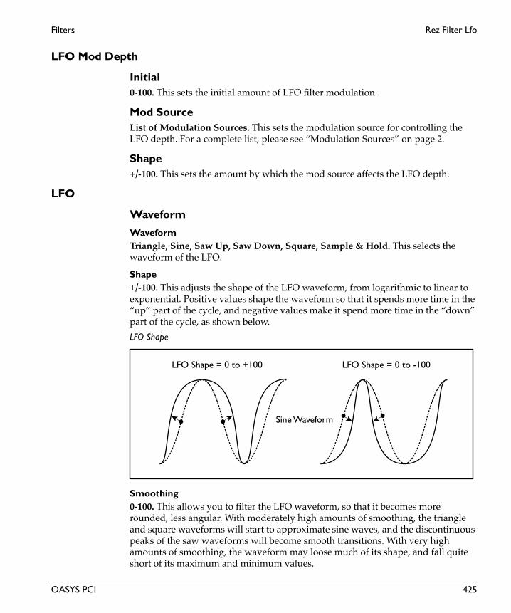
Filters Rez Filter Lfo
LFO Mod Depth
Initial0-100. This sets the initial amount of LFO filter modulation.
Mod SourceList of Modulation Sources. This sets the modulation source for controlling the LFO depth. For a complete list, please see “Modulation Sources” on page 2.
Shape+/-100. This sets the amount by which the mod source affects the LFO depth.
LFO
Waveform
WaveformTriangle, Sine, Saw Up, Saw Down, Square, Sample & Hold. This selects the waveform of the LFO.
Shape+/-100. This adjusts the shape of the LFO waveform, from logarithmic to linear to exponential. Positive values shape the waveform so that it spends more time in the “up” part of the cycle, and negative values make it spend more time in the “down” part of the cycle, as shown below.
LFO Shape
Smoothing0-100. This allows you to filter the LFO waveform, so that it becomes more rounded, less angular. With moderately high amounts of smoothing, the triangle and square waveforms will start to approximate sine waves, and the discontinuous peaks of the saw waveforms will become smooth transitions. With very high amounts of smoothing, the waveform may loose much of its shape, and fall quite short of its maximum and minimum values.
LFO Shape = 0 to +100 LFO Shape = 0 to -100
Sine Waveform
OASYS PCI 425
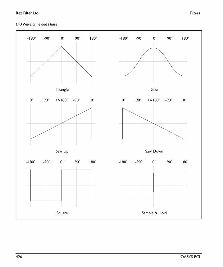
Rez Filter Lfo Filters
Eng
lish
LFO Waveforms and Phase
0˚ 90˚ 180˚-90˚-180˚ 0˚ 90˚ 180˚-90˚-180˚
+/-180˚ -90˚ 0˚90˚0˚
0˚ 90˚ 180˚-90˚-180˚ 0˚ 90˚ 180˚-90˚-180˚
+/-180˚ -90˚ 0˚90˚0˚
Triangle Sine
Saw DownSaw Up
Sample & HoldSquare
426 OASYS PCI

Filters Rez Filter Lfo
LFO ControlFrequency Knob, Manual Tempo, MIDI Tempo. The LFO speed can be controlled either by the Frequency knob (including the mod source), the Manual Tempo knob, or by MIDI Tempo (derived from MIDI clocks).
If this is set to Frequency Knob, then the LFO speed will be controlled by the settings in the Frequency section, including the mod source and amount.
If this is set to Manual Tempo, then the Manual Tempo knob will set the basic tempo, and the note value set in the Subdivisions menu will control the LFO speed.
If this is set to MIDI Tempo, then incoming MIDI Clocks will set the basic tempo, and the note value set in the Subdivisions menu will control the LFO speed.
Phase
Initial PhaseThis sets the point in the waveform at which the LFO starts. Whenever the Phase Reset controller is received, the LFO will start from the Initial Phase point.
Phase ResetList of Modulation Sources. This sets the MIDI controller which will reset the LFO’s phase to the Initial Phase point. You can use this to trigger the LFO from a MIDI sequencer, so that it always starts at the same point. This is especially useful in conjunction with MIDI Tempo synchronization. For a complete list of mod sources, please see “Modulation Sources” on page 2.
To make sure that the LFO’s phase is correct when working with a sequencer, it’s best to include the phase reset controller every few bars in the sequence, so that no matter where you start playback, the LFO will be reset appropriately.
FrequencyThe controls in the Frequency section only apply when the LFO Control is set to Frequency Knob.
Frequency0.00-20.00Hz. This controls the speed of the LFO when the LFO Control is set to Frequency Knob.
Frequency ModList of Modulation Sources. This sets the modulation source for controlling the LFO speed. For a complete list, please see “Modulation Sources” on page 2.
Mod Amount+/-100. This sets the amount by which the mod source affects the LFO speed.
Tempo
Manual Tempo40-240 bpm. This sets the tempo when the LFO Control is set to Manual Tempo.
OASYS PCI 427

Rez Filter Lfo Filters
Eng
lish
Subdivision1/32, 1/32 dotted, 1/16, 1/16 dotted, 1/16 triplet, 1/8, 1/8 dotted, 1/8 triplet, 1/4, 1/4 dotted, 1/4 triplet, 1/2, 1/2 dotted, 1/2 triplet, 1 whole note, 2 whole notes. This sets the note value of a single LFO waveform cycle when the LFO Control is set to either Manual Tempo or MIDI Tempo.
428 OASYS PCI

Filters Rez Filter Seq
Rez Filter SeqThis effect combines a resonant multimode, multi-pole filter with an ADSR envelope and an analog-style sequencer.
Input
Level-INF, -69.0 to 0.0dB. This sets the input level for the effect. It does not affect the dry signal.
Filter
Cutoff0-100. This controls the cutoff frequency of the filter. The meaning of the cutoff frequency will change depending on the filter mode.
When the filter is set to Lowpass mode, frequencies above the cutoff are attenuated, and frequencies below the cutoff are passed through unchanged.
When the filter is set to Highpass mode, frequencies below the cutoff will be attenuated, and frequencies above the cutoff will pass through unchanged.
When the filter is set to Bandpass mode, frequencies both above and below the cutoff will be attenuated, and only frequencies right at the cutoff will pass through unchanged.
Note that the Envelope and Key Track parameters also affect the cutoff frequency.
This control has extra smoothing on the DSP, to ensure zipper-free modulation. If instantaneous modulation is desired (such as modulation via velocity), modulate the Envelope control instead.
Seq Mod Amt+/-100. This sets the amount of cutoff modulation from the sequencer.
Key Track+/-100. This adjusts the filter cutoff in response to incoming MIDI notes, centered on E4, as shown below. Note that you can also modulate any parameter using the “Key Tracking” modulators in the Mod Palette.
OASYS PCI 429

Rez Filter Seq Filters
Eng
lish
Key Tracking
Resonance0-100. Resonance emphasizes the frequencies around the cutoff frequency. At 0, there is no emphasis, and frequencies beyond the cutoff will simply diminish smoothly. At very high settings, the resonance can be heard as a separate, whistling pitch. At medium settings, the resonance will alter the timbre of the filter, but will not usually be heard as a separate pitch. The timbre and intensity of the resonance will change depending on the filter Type setting - 4 Pole, 2 Pole, or 2 Pole > 2 Pole.
Seq Mod Amt+/-100. This sets the amount of resonance modulation from the sequencer.
Envelope0-100. The ADSR envelope can be used to control the filter cutoff frequency, adding to the setting on the Cutoff knob. When Envelope is set to 0, the envelope will have no effect. At +100, the envelope will open the filter all the way at its peak, even if Cutoff is set to 0.
Envelope amount affect on cutoff frequency
E4MIDI Note
Valu
e0
+100
-100A0 C8
Key Track amount
-100
+100
0
+50
-50
+100
0
Enve
lope
am
ount
430 OASYS PCI

Filters Rez Filter Seq
Attack0-100. This sets the attack time of the filter envelope, which controls how long it takes from the moment that the key is pressed until the envelope reaches its peak.
Decay 0-100. This sets the decay time of the filter envelope, which controls how long it takes the envelope to fall to the sustain level after the attack is complete.
Sustain0-100. This sets the sustain level for the filter envelope. After the decay time is complete, the envelope will stay at this level as long as the note is held.
Release0-100. This sets the release time of the filter envelope, which controls how long it takes the envelope to fall to zero after the note is released.
ADSR Envelope
ModeLowpass, Highpass, Bandpass. This selects whether the filter will cut high frequencies (Lowpass), cut low frequencies (Highpass), or cut all frequencies above and below the cutoff point (Bandpass).
Lowpass. Frequencies above the cutoff will be attenuated, and frequencies below the cutoff will pass through unchanged.
Highpass. Frequencies below the cutoff will be attenuated, and frequencies above the cutoff will pass through unchanged.
Bandpass. Frequencies both above and below the cutoff will be attenuated, and only frequencies right at the cutoff will pass through unchanged.
Attack time Decay time Release timeSustain while
SustainLevel
holding note
Enve
lope
Am
ount
OASYS PCI 431

Rez Filter Seq Filters
Eng
lish
Type4 Pole, 2 Pole, 2 Pole > 2 Pole. This parameter selects the amount of frequency attenuation in the filter, and the character of the resonance.
4 Pole. This is a 24dB per octave filter. Of the three types, the 4 Pole offers the greatest attenuation of frequencies beyond the cutoff, coupled with a resonance slightly more delicate than the 2 Pole type. Many classic analog synths used this general type of filter.
2 Pole. This is a 12dB per octave filter. Compared to the 4 Pole, this offers significantly less attenuation of frequencies beyond the cutoff, but with slightly more pronounced resonance.
2 Pole > 2 Pole. This is two 12dB per octave filters in series. Of the three types, this offers by far the most extreme resonance effect. Compared with the 4 Pole, it has just a little less attenuation of frequencies beyond the cutoff.
LFO Mod Depth
Frequency0.00-10000Hz. This sets the frequency of the LFO.
WaveformSine, Triangle, Saw, Square. This selects the shape of the LFO.
LFO ResetList of Modulation Sources. This sets the modulation source for resetting the LFO phase. For a complete list, please see “Modulation Sources” on page 2.
Mod Amount+/-100. This sets the amount by which the mod source affects the LFO speed.
Cutoff Mod+/-100. This sets the amount by which the LFO affects the filter cutoff.
Resonance Mod+/-100. This sets the amount by which the LFO affects the filter resonance.
Baseline Mod+/-100. This sets the amount by which the LFO affects the sequencer baseline.
Step Sequencer
Initial StateRun, Stop. This controls whether the sequence is running or stopped when first opened.
432 OASYS PCI

Filters Rez Filter Seq
Run/Stop ModList of Modulation Sources. This sets the modulation source for starting and stopping the sequence. For a complete list, please see “Modulation Sources” on page 2.
Run/Stop ModeMomentary, Toggle. This determines the behavior of the run/stop modulator.
Momentary. The the run/stop state is changed only as long as the switch is on. When the switch is released, it returns to the previous state.
Toggle. The switch turns the sequencer on and off alternately. Switching once turns it on; switching again turns it off.
Tempo SourceKnob, Midi Tempo. This sets whether the sequencer will use the tempo set by the Tempo knob, or tempo received via MIDI.
Tempo40-240Hz. This sets the tempo, in beats per minute, when the Tempo Source is set to Manual Tempo. If the Tempo Source is set to MIDI Tempo, this knob is ignored.
Step Value1/32, 1/32 dotted, 1/16, 1/16 dotted, 1/16 triplet, 1/8, 1/8 dotted, 1/8 triplet, 1/4, 1/4 dotted, 1/4 triplet, 1/2, 1/2 dotted, 1/2 triplet, 1 bar, 2 bars. This sets the note value of the steps in the sequence.
Loop Start1-16. The sequence will always start at step 1, but when it begins to repeat, it will jump to the step specified here. You can modulate this via MIDI, to create fluctuating patterns.
Loop End1-16. This sets the end step for the sequence. When the sequence completes this step, it will return to the Loop Start.
Step Width0-100. This sets the duration of the sequencer pulses. This parameter is particularly suited to real-time modulation.
Attack0-100. This sets the attack time for the sequencer pulses.
Decay0-100. This sets the decay time for the sequencer pulses.
OASYS PCI 433

Rez Filter Seq Filters
Eng
lish
Sequencer Levels
Step 1-16+/-100. This sets the output level for each step.
Baseline+/-100. This allows you to move the filter cutoff underneath the sequence, without affecting the Step 1-16 levels. It’s a very different effect than moving the Cutoff or Seq Amt knobs–try it out!
434 OASYS PCI

Filters Rez Filter+Amp
Rez Filter+AmpThis effect provides a resonant multimode, multi-pole filter, filter and amplitude ADSR envelopes, and an LFO which can be routed to both cutoff and resonance.
Input
Level-INF, -69.0 to 0.0dB. This sets the input level for the effect. It does not affect the dry signal.
If you are using high amounts of resonance, you may need to turn down the input level to avoid clipping.
Filter
Cutoff0-100. This controls the cutoff frequency of the filter. The meaning of the cutoff frequency will change depending on the filter mode.
When the filter is set to Lowpass mode, frequencies above the cutoff are attenuated, and frequencies below the cutoff are passed through unchanged.
When the filter is set to Highpass mode, frequencies below the cutoff will be attenuated, and frequencies above the cutoff will pass through unchanged.
When the filter is set to Bandpass mode, frequencies both above and below the cutoff will be attenuated, and only frequencies right at the cutoff will pass through unchanged.
Note that the Envelope and Key Track parameters also affect the cutoff frequency.
This control has extra smoothing on the DSP, to ensure zipper-free modulation. If instantaneous modulation is desired (such as modulation via velocity), modulate the Envelope control instead.
Resonance0-100. Resonance emphasizes the frequencies around the cutoff frequency. At 0, there is no emphasis, and frequencies beyond the cutoff will simply diminish smoothly. At very high settings, the resonance can be heard as a separate, whistling pitch. At medium settings, the resonance will alter the timbre of the filter, but will not usually be heard as a separate pitch. The timbre and intensity of the resonance will change depending on the filter Type setting - 4 Pole, 2 Pole, or 2 Pole > 2 Pole.
Envelope0-100. The ADSR envelope can be used to control the filter cutoff frequency, adding to the setting on the Cutoff knob. When Envelope is set to 0, the envelope will have
OASYS PCI 435

Rez Filter+Amp Filters
Eng
lish
no effect. At +100, the envelope will open the filter all the way at its peak, even if Cutoff is set to 0.
Envelope amount affect on cutoff frequency
Key Track+/- 100. This adjusts the filter cutoff in response to incoming MIDI notes, as shown below. Note that you can also modulate any parameter using the “Key Tracking” modulators in the Mod Palette.
Key Tracking
Attack0-100. This sets the attack time of the filter envelope, which controls how long it takes from the moment that the key is pressed until the envelope reaches its peak.
Decay 0-100. This sets the decay time of the filter envelope, which controls how long it takes the envelope to fall to the sustain level after the attack is complete.
+100
0
Enve
lope
am
ount
E4MIDI Note
Valu
e
0
+100
-100A0 C8
Key Track amount
-100
+100
0
+50
-50
436 OASYS PCI

Filters Rez Filter+Amp
Sustain0-100. This sets the sustain level for the filter envelope. After the decay time is complete, the envelope will stay at this level as long as the note is held.
Release0-100. This sets the release time of the filter envelope, which controls how long it takes the envelope to fall to zero after the note is released.
ADSR Envelope
ModeLowpass, Highpass, Bandpass. This selects whether the filter will cut high frequencies (Lowpass), cut low frequencies (Highpass), or cut all frequencies above and below the cutoff point (Bandpass).
Lowpass. Frequencies above the cutoff will be attenuated, and frequencies below the cutoff will pass through unchanged.
Highpass. Frequencies below the cutoff will be attenuated, and frequencies above the cutoff will pass through unchanged.
Bandpass. Frequencies both above and below the cutoff will be attenuated, and only frequencies right at the cutoff will pass through unchanged.
Type4 Pole, 2 Pole, 2 Pole > 2 Pole. This parameter selects the amount of frequency attenuation in the filter, and the character of the resonance.
4 Pole. This is a 24dB per octave filter. Of the three types, the 4 Pole offers the greatest attenuation of frequencies beyond the cutoff, coupled with a resonance slightly more delicate than the 2 Pole type. Many classic analog synths used this general type of filter.
Attack time Decay time Release timeSustain while
SustainLevel
holding note
Enve
lope
Am
ount
OASYS PCI 437

Rez Filter+Amp Filters
Eng
lish
2 Pole. This is a 12dB per octave filter. Compared to the 4 Pole, this offers significantly less attenuation of frequencies beyond the cutoff, but with slightly more pronounced resonance.
2 Pole > 2 Pole. This is two 12dB per octave filters in series. Of the three types, this offers by far the most extreme resonance effect. Compared with the 4 Pole, it has just a little less attenuation of frequencies beyond the cutoff.
LFO Mod
Frequency0.00-100.00Hz. This sets the frequency of the LFO,
WaveformLFO Sine, LFO Triangle, LFO Saw, LFO Square. This selects the shape of the LFO.
Filter CutoffOn, Off. This enables and disables modulation of filter cutoff by the LFO.
ResonanceOn, Off. This enables and disables modulation of filter resonance by the LFO.
Depth0-100. This sets the depth of the LFO modulation.
Mod SourceList of Modulation Sources. This sets the modulation source for controlling the LFO depth. For a complete list, please see “Modulation Sources” on page 2.
Mod Amount+/-100. This sets the amount by which the mod source affects the LFO depth.
AmplifierThese parameters control an ADSR envelope dedicated to the output volume. For a graphic explaining ADSR envelopes, see the figure “ADSR Envelope,” above.
Attack0-100. This sets the attack time of the amplitude envelope, which controls how long it takes from the moment that the key is pressed until the envelope reaches its peak.
Decay 0-100. This sets the decay time of the amplitude envelope, which controls how long it takes the envelope to fall to the sustain level after the attack is complete.
438 OASYS PCI

Filters Rez Filter+Amp
Sustain0-100. This sets the sustain level for the amplitude envelope. After the decay time is complete, the envelope will stay at this level as long as the note is held.
Release0-100. This sets the release time of the amplitude envelope, which controls how long it takes the envelope to fall to zero after the note is released.
Volume0-100. This controls the overall output volume of the effect.
OASYS PCI 439

St Auto Wah Filters
Eng
lish
St Auto WahThis is a stereo-input, stereo-output wah filter, which can be swept either by an envelope follower or by a MIDI controller.
Input
Level-INF, -69.0 to 0.0dB. This sets the input level for the effect. It does not affect the dry signal.
St.Wah/Auto Wah
L Cutoff Bottom0-100. This sets the frequency of the left-channel wah when the modulation is at its minimum value.
L Cutoff Top0-100. This sets the frequency of the left-channel wah when the modulation is at its maximum value.
R Cutoff Bottom0-100. This sets the frequency of the right-channel wah when the modulation is at its minimum value.
R Cutoff Top0-100. This sets the frequency of the right-channel wah when the modulation is at its maximum value.
Sweep ModeAuto, Mod Source. This determines how the wah will be controlled.
Auto. The wah will be controlled by the envelope follower.
Mod Source. The wah will be controlled directly from the MIDI mod source.
Mod SourceList of Modulation Sources. This sets the modulation source for controlling the wah sweep, when Sweep Mode is set to Mod Source. For a complete list of sources, please see “Modulation Sources” on page 2.
Mod Response0-100. This sets the rate at which the wah frequency changes in response to the modulator.
440 OASYS PCI

Filters St Auto Wah
Resonance0-100. This sets the resonance of the wah filter. Higher resonances will emphasize the cutoff frequency.
Filter ModeLPF, BPF. This sets the type of filter used for the wah.
LPF. The wah will use a lowpass filter.
BPF. The wah will use a bandpass filter.
Envelope
Envelope SelectL/R Mix, L Only, R Only. This selects the input which will drive the envelope follower.
Sens0-100. This sets the input sensitivity of the envelope follower.
Shape+/-100. Sets the curve of the envelope follower, as shown below.
Envelope Shape
Output
Wet/DryDry, 1:99-99:1, Wet. This sets the balance between the effect and the dry signal.
Level
Time
0 to +100
0 to -100
OriginalEnvelope
OASYS PCI 441

St Auto Wah Filters
Eng
lish
Wet/Dry ModList of Modulation Sources. This sets the modulation source for controlling the wet/dry mix. For a complete list, please see “Modulation Sources” on page 2.
Mod Amount+/-100. This sets the amount by which the mod source affects the wet/dry mix.
442 OASYS PCI

Filters Stereo Enhancer
Stereo EnhancerThis stereo-input, stereo-output effect enhances the stereo image, and adds presence to the sound. It’s useful when you wish to emphasize a stereo effect, or to create a stereo image from a monaural source.
Input
Level-INF, -69.0 to 0.0dB. This sets the input level for the effect. It does not affect the dry signal.
Pre-EQ
Low Freq20-2000Hz. This sets the frequency of the pre-effect low shelving EQ.
Low Gain+/-18.1dB. This sets the amount of boost or cut for the pre-effect low shelving EQ.
High Freq20-2000Hz. This sets the frequency of the pre-effect high shelving EQ.
High Gain+/-18.1dB. This sets the amount of boost or cut for the pre-effect high shelving EQ.
Stereo Dyna Exciter
Emphasis Point0-100. This sets the frequency to be emphasized. Higher values will emphasize lower frequencies.
Emphasis ModList of Modulation Sources. This selects the modulation source for controlling the emphasis point. For a complete list, please see “Modulation Sources” on page 2.
Mod Amount+/-100. This sets the amount by which the mod source affects the emphasis point.
Blend+/-100. This parameter controls the intensity of the exciter effect. Positive values emphasize different frequency patterns than negative values.
OASYS PCI 443

Stereo Enhancer Filters
Eng
lish
Blend ModList of Modulation Sources. This sets the modulation source for controlling the blend. For a complete list, please see “Modulation Sources” on page 2.
Mod Amount+/-100. This sets the amount by which the mod source affects the blend.
Stereo Enhancer
Width0-100. This sets the degree to which the Enhancer effect is applied.
Width ModList of Modulation Sources. This sets the modulation source for controlling the width. For a complete list, please see “Modulation Sources” on page 2.
Mod Amount+/-100. This sets the amount by which the mod source affects the width.
Left Delay Time0.0-50.0ms. These parameters set the delay time for the left and right channels. Specifying a slightly different delay time for the left and right channel will add a stereo image, depth, and width to the sound.
Right Delay Time0.0-50.0ms. This sets the delay time for the right channel.
Wide Stereo
Wide StereoOff, On. This adds additional stereo width to the signal.
Position0-100. This adjusts the apparent listening position.
Output
Wet/DryDry, 1:99-99:1, Wet. This sets the balance between the effect and the dry signal.
Wet/Dry ModList of Modulation Sources. This sets the modulation source for controlling the wet/dry mix. For a complete list, please see “Modulation Sources” on page 2.
444 OASYS PCI

Filters Stereo Enhancer
Mod Amount+/-100. This sets the amount by which the mod source affects the wet/dry amount.
OASYS PCI 445

Talking Mod Filters
Eng
lish
Talking ModThis effect adds vocal formants to the input signal. By modulating the effect in real-time, you can create an interesting effect that makes almost any sound appear to be talking.
Input
SourceLeft, L + R. This is a mono-in, stereo-out effect. Stereo signals are preserved in the dry mix at the output, but the effect itself has only a single, mono input.
When this is set to Left, only the left channel will be routed into the effect.
When this is set to L + R, the left and right channels will be summed together, and then routed into the effect.
Level-INF, -69.0 to 0.0dB. This sets the input level for the effect. It does not affect the dry signal.
Formant Control
Control SourceManual, Mod Source, LFO. This determines how the movement between the vowel shapes will be controlled.
Manual. The vowel shapes will be controlled by the Manual knob.
Mod Source. The vowel shapes will be controlled directly from the MIDI mod source.
LFO. The vowel shapes will be controlled by the LFO.
Manual0-100. This knob controls the movement between vowel shapes when the Control Source is set to Manual.
Mod SourceList of Modulation Sources. This sets the modulation source for controlling the vowel shapes when the Control Source is set to Mod Source. For a complete list of modulators, please see “Modulation Sources” on page 2.
LFO Freq0.00-20.00Hz. This sets the frequency of the LFO.
446 OASYS PCI

Filters Talking Mod
LFO Shape+/-100. This adjusts the shape of the LFO waveform. Positive values shape the curve so that it spends more time in the “up” part of the cycle, and negative values make it spend more time in the “down” part of the cycle, as shown below.
LFO Shape
FormantThese parameters assign vowel sounds to the minimum, center, and maximum values of the controller. For example, let’s say that Mod Wheel is selected as the modulation source, and Voice Top is set to AH, Voice Centeris set to IH, and Voice Bottom is set to UU. Moving the wheel up from 0 will then produce the vowel sounds “uu”, “ih”, and then “ah.”
BottomAH, IH, UU, EE, OH. This is the vowel sound at the minimum value of the controller.
CenterAH, IH, UU, EE, OH. This is the vowel sound at the middle value of the controller.
TopAH, IH, UU, EE, OH. This is the vowel sound at the maximum value of the controller.
Formant Shift+/-100. This parameter adjusts the frequency range to which the effect is applied. If you wish to apply the effect to a higher-frequency sound, set this parameter to a higher value; to apply the effect to a lower-frequency sound, set this to a lower value.
LFO Shape = 0 to +100 LFO Shape = 0 to -100
Sine Waveform
OASYS PCI 447

Talking Mod Filters
Eng
lish
Resonance0-100. This parameter sets the intensity of the vowel resonance. Higher resonance settings will add more character to the sound.
Talking Modulator
Output
Wet/DryDry, 1:99-99:1, Wet. This sets the balance between the effect and the dry signal.
Wet/Dry ModList of Modulation Sources. This sets the modulation source for controlling the wet/dry mix. For a complete list, please see “Modulation Sources” on page 2.
Mod Amount+/-100. This sets the amount by which the mod source affects the wet/dry amount.
+ MaxZero– Max
Voice Bottom Voice Center Voice Top
U
I
AA
O
E
Zero+ Max
448 OASYS PCI

Filters Wide Stereo
Wide StereoThis effect enhances the perception of stereo imaging in the input signal.
Input
Level-INF, -69.0 to 0.0dB. This sets the input level for the effect. It does not affect the dry signal.
Stereo Enhancer
Width0-100. This sets the degree to which the Enhancer effect is applied.
Width ModList of Modulation Sources. This sets the modulation source for controlling the width. For a complete list, please see “Modulation Sources” on page 2.
Mod Amount+/-100. This sets the amount by which the mod source affects the width.
Left Delay Time0.0-50.0ms. These parameters set the delay time for the left and right channels. Specifying a slightly different delay time for the left and right channel will add a stereo image, depth, and width to the sound.
Right Delay Time0.0-50.0ms. This sets the delay time for the right channel.
Wide Stereo
Wide StereoOff, On. This adds additional stereo width to the signal.
Position0-100. This adjusts the apparent listening position.
Output
Wet/DryDry, 1:99-99:1, Wet. This sets the balance between the effect and the dry signal.
OASYS PCI 449

Wide Stereo Filters
Eng
lish
Wet/Dry ModList of Modulation Sources. This sets the modulation source for controlling the wet/dry mix. For a complete list, please see “Modulation Sources” on page 2.
Mod Amount+/-100. This sets the amount by which the mod source affects the wet/dry amount.
450 OASYS PCI

Flangers

Envelope Flanger Flangers
Eng
lish
Envelope FlangerThis is a mono-input, mono-output flanger, based on an envelope instead of an LFO. You can trigger the envelope via MIDI, and also simply control the flanger directly from a MIDI controller.
Input
SourceLeft, L + R. This is a mono-in, mono-out effect. Stereo signals are preserved in the dry mix at the output, but the effect itself has only a single, mono input.
When this is set to Left, only the left channel will be routed into the effect.
When this is set to L + R, the left and right channels will be summed together, and then routed into the effect.
Level-INF, -69.0 to 0.0dB. This sets the input level for the effect. It does not affect the dry signal.
Envelope Flanger
Min Delay0.0-50.0ms. This sets the delay when the envelope or mod source is at minimum.
Max Delay0.0-50.0ms. This sets the delay when the envelope or mod source is at maximum.
Feedback+/-100. This controls the amount of feedback in the flanger. Higher feedback settings result in a more extreme sound.
Hi Damping0-100. This adjusts the amount of high frequency damping in the feedback loop.
Flanger Control
Sweep ModeEG, Mod Source. This determines how the flanger will be controlled.
EG. The flanger will be controlled by the envelope generator (EG).
Mod Source. The flanger will be controlled directly by the MIDI mod source.
452 OASYS PCI

Flangers Envelope Flanger
EG Trigger/ModList of Modulation Sources. When Sweep Mode is set to EG, this selects the modulation source that triggers the envelope. When Sweep Mode is set to Mod Source, this selects the modulation source that controls the flanger. For a complete list of modulation sources, please see “Modulation Sources” on page 2.
Note EG RetrigOn, Off. This determines the way that the envelope triggers when the Trigger Source is set to Note Gate or Note Gate + Sustain.
On. When this is on, the envelope will be triggered whenever a key is pressed.
Off. When this is off, the envelope will only be retriggered after all currently held notes have been released.
EG Attack0-100. This sets the attack time of the envelope–the time that it takes to reach its maximum value after being triggered.
EG Decay0-100. This sets the release time of the envelope–the time that it takes to fall back to its minimum value after the trigger is released.
Output
ModeMono, Stereo. This controls whether the effect output is mono or simulated stereo.
When this is set to Mono, the output is in mono.
When this is set to Stereo, the output is simulated stereo, with the right effect output inverted. Note that this simulated stereo effect is not mono-compatible.
Wet/DryDry, 1:99-99:1, Wet. This sets the balance between the effect and the dry signal.
Wet/Dry ModList of Modulation Sources. This sets the modulation source for controlling the wet/dry mix. For a complete list, please see “Modulation Sources” on page 2.
Mod Amount+/-100. This sets the amount by which the mod source affects the wet/dry mix.
Invert Wet PhaseOn, Off. This allows you to invert the phase of the wet signal.
OASYS PCI 453

Flanger Flangers
Eng
lish
FlangerThis is a mono-input, mono-output flanger.
Input
SourceLeft, L + R. This is a mono-in, mono-out effect. Stereo signals are preserved in the dry mix at the output, but the effect itself has only a single, mono input.
When this is set to Left, only the left channel will be routed into the effect.
When this is set to L + R, the left and right channels will be summed together, and then routed into the effect.
Level-INF, -69.0 to 0.0dB. This sets the input level for the effect. It does not affect the dry signal.
Flanger
Delay0.0-50.0ms. This sets the center delay for the flanger.
Depth0-100. This controls the depth of LFO modulation.
Feedback+/-100. This controls the amount of feedback in the flanger. Higher feedback settings result in a more extreme sound.
Hi Damping0-100. This adjusts the amount of high frequency damping in the feedback loop.
LFO
WaveformTriangle, Sine. This selects the waveform for the LFO.
Shape+/-100. This adjusts the shape of the LFO waveform. Positive values shape the curve so that it spends more time in the “up” part of the cycle, and negative values make it spend more time in the “down” part of the cycle, as shown below.
454 OASYS PCI

Flangers Flanger
LFO Shape
Frequency0.00-20.00Hz. This controls the speed of the LFO.
Frequency ModList of Modulation Sources. This sets the modulation source for controlling the LFO frequency. For a complete list, please see “Modulation Sources” on page 2.
Mod Amount+/-100. This sets the amount by which the mod source affects the LFO frequency.
Output
ModeMono, Stereo. This controls whether the effect output is mono or simulated stereo.
When this is set to Mono, the output is in mono.
When this is set to Stereo, the output is simulated stereo, with the right effect output inverted. Note that this simulated stereo effect is not mono-compatible.
Wet/DryDry, 1:99-99:1, Wet. This sets the balance between the effect and the dry signal.
Wet/Dry ModList of Modulation Sources. This sets the modulation source for controlling the wet/dry mix. For a complete list, please see “Modulation Sources” on page 2.
Mod Amount+/-100. This sets the amount by which the mod source affects the wet/dry mix.
LFO Shape = 0 to +100 LFO Shape = 0 to -100
Sine Waveform
OASYS PCI 455

St Env Flanger Flangers
Eng
lish
St Env FlangerThis is a stereo-in, stereo-out flanger based on an envelope instead of an LFO. You can trigger the envelope via MIDI, and also simply control the flanger frequency directly from a MIDI controller.
Input
Level-INF, -69.0 to 0.0dB. This sets the input level for the effect. It does not affect the dry signal.
Stereo Envelope Flanger
Left Delay Min0.0-50.0ms. This sets the left delay time when the envelope or mod source is at minimum.
Left Delay Max 0.0-50.0ms. This sets the left delay time when the envelope or mod source is at maximum.
Right Delay Min0.0-50.0ms. This sets the right delay time when the envelope or mod source is at minimum.
Right Delay Max 0.0-50.0ms. This sets the right delay time when the envelope or mod source is at maximum.
Feedback+/-100. This controls the amount of feedback in the flanger. Higher feedback settings result in a more extreme sound.
High Damp0-100. This controls the amount of high frequency damping in the flanger feedback.
Spread+/-100. This controls the width of the effect’s stereo image, without affecting the dry signal. A value of +100 gives the widest stereo image, and a value of 0 collapses the output to mono. Negative values will reverse the left and right channels of the effect output.
456 OASYS PCI

Flangers St Env Flanger
Flanger Control
Sweep ModeEG, Mod Source. This determines how the flanger will be controlled.
EG. The flanger will be controlled by the envelope generator (EG).
Mod Source. The flanger will be controlled directly by the MIDI mod source.
EG Trigger/ModList of Modulation Sources. When Sweep Mode is set to EG, this selects the modulation source that triggers the envelope. When Sweep Mode is set to Mod Source, this selects the modulation source that controls the flanger. For a complete list of modulation sources, please see “Modulation Sources” on page 2.
Note EG RetrigOn, Off. This determines the way that the envelope triggers when the Trigger Source is set to Note Gate or Note Gate + Sustain.
On. When this is on, the envelope will be triggered whenever a key is pressed.
Off. When this is off, the envelope will only be retriggered after all currently held notes have been released.
EG Attack0-100. This sets the attack time of the envelope–the time that it takes to reach its maximum value after being triggered.
EG Decay0-100. This sets the release time of the envelope–the time that it takes to fall back to its minimum value after the trigger is released.
Output
Wet/DryDry, 1:99-99:1, Wet. This sets the balance between the effect and the dry signal.
Wet/Dry ModList of Modulation Sources. This sets the modulation source for controlling the wet/dry mix. For a complete list, please see “Modulation Sources” on page 2.
Mod Amount+/-100. This sets the amount by which the mod source affects the wet/dry mix.
Invert Wet PhaseOn, Off. This allows you to invert the phase of the wet signal.
OASYS PCI 457

St Flanger Flangers
Eng
lish
St FlangerThis is a stereo-in, stereo-out flanger effect.
Input
Level-INF, -69.0 to 0.0dB. This sets the input level for the effect. It does not affect the dry signal.
Stereo Flanger
Delay0.0-50.0ms. This sets the center delay for the flanger.
Depth0-100. This controls the depth of LFO modulation.
Feedback ModeNormal, Cross. This selects the feedback routing for the flanger.
Normal. The channels will feed back into themselves, left into left and right into right.
Cross. The channels will feed back into each other, left into right and right into left.
Feedback+/-100. This controls the amount of feedback in the flanger. Higher feedback settings result in a more extreme sound.
Hi Damping0-100. This adjusts the amount of high frequency damping in the feedback loop.
Spread+/-100. This controls the width of the effect’s stereo image, without affecting the dry signal. A value of +100 gives the widest stereo image, and a value of 0 collapses the output to mono. Negative values will reverse the left and right channels of the effect output.
LFO
WaveformTriangle, Sine. This selects the waveform for the LFO.
458 OASYS PCI

Flangers St Flanger
Shape+/-100. This adjusts the shape of the LFO waveform. Positive values shape the curve so that it spends more time in the “up” part of the cycle, and negative values make it spend more time in the “down” part of the cycle, as shown below.
LFO Shape
L/R Phase+/-180. This sets the phase difference between the LFOs for the right and left channels. Off-setting the phase between the two, as shown below, enhances the stereo effect–although with panning in particular, the two channels must contain fairly discrete material for this effect to be noticeable.
LFO Phase
Frequency0.00-20.00Hz. This controls the speed of the LFO.
LFO Shape = 0 to +100 LFO Shape = 0 to -100
Sine Waveform
0° +90° +180°
0°–90°–180°
OASYS PCI 459

St Flanger Flangers
Eng
lish
Frequency ModList of Modulation Sources. This sets the modulation source for controlling the LFO speed. For a complete list, please see “Modulation Sources” on page 2.
Mod Amount+/-20.00Hz. This sets the amount by which the mod source affects the LFO speed.
Output
Wet/DryDry, 1:99-99:1, Wet. This sets the balance between the effect and the dry signal.
Wet/Dry ModList of Modulation Sources. This sets the modulation source for controlling the wet/dry mix. For a complete list, please see “Modulation Sources” on page 2.
Mod Amount+/-100. This sets the amount by which the mod source affects the wet/dry mix.
460 OASYS PCI

Flangers St RandomFlange
St RandomFlangeThis is a stereo-in, stereo-out flanger, with step-shaped and sample-and-hold waveforms.
Input
Level-INF, -69.0 to 0.0dB. This sets the input level for the effect. It does not affect the dry signal.
Stereo Random Flanger
Delay0.0-50.0ms. This sets the center delay for the flanger.
Depth0-100. This controls the depth of LFO modulation.
Depth ModList of Modulation Sources. This sets the modulation source for controlling the LFO depth. For a complete list, please see “Modulation Sources” on page 2.
Mod Amount+/-100. This sets the amount by which the mod source affects the LFO depth.
Feedback ModeNormal, Cross. This selects the feedback routing for the flanger.
Normal. The channels will feed back into themselves, left into left and right into right.
Cross. The channels will feed back into each other, left into right and right into left.
Feedback+/-100. This controls the amount of feedback in the flanger. Higher feedback settings result in a more extreme sound.
Hi Damping0-100. This adjusts the amount of high frequency damping in the feedback loop.
Spread+/-100. This controls the width of the effect’s stereo image, without affecting the dry signal. A value of +100 gives the widest stereo image, and a value of 0 collapses the
OASYS PCI 461

St RandomFlange Flangers
Eng
lish
output to mono. Negative values will reverse the left and right channels of the effect output.
LFO Control
WaveformStep Triangle, Step Sine, Random. This selects the main waveform for the LFO.
L/R Phase+/-180. This sets the phase difference between the LFOs for the right and left channels. Off-setting the phase between the two, as shown below, enhances the stereo effect.
LFO Phase
Frequency0.00-20.00Hz. This sets the frequency for the main LFO.
Step Freq0.00-50.00Hz. This sets the frequency of the LFO steps. If the Random waveform is being used, then this will determine the frequency of the sample-and-hold effect.
Frequency ModList of Modulation Sources. This sets the modulation source for controlling the LFO frequencies. The same modulator can be used for both the main LFO and the step LFO. For a complete list, please see “Modulation Sources” on page 2.
0° +90° +180°
0°–90°–180°
462 OASYS PCI

Flangers St RandomFlange
Mod Amount+/-20.00Hz. This sets the amount by which the mod source affects the frequency of the main LFO.
Step Amt+/-50.00Hz. This sets the amount by which the mod source affects the frequency of the step LFO.
Random Step LFO
Output
Wet/DryDry, 1:99-99:1, Wet. This sets the balance between the effect and the dry signal.
Wet/Dry ModList of Modulation Sources. This sets the modulation source for controlling the wet/dry mix. For a complete list, please see “Modulation Sources” on page 2.
Mod Amount+/-100. This sets the amount by which the mod source affects the wet/dry mix.
Invert Wet PhaseOn, Off. This allows you to invert the phase of the wet signal.
LFO Step Freq
LFO Frequency
LFO Step Freq
Step-Tri Random
OASYS PCI 463

St TempoFlanger Flangers
Eng
lish
St TempoFlangerThis is a stereo-in, stereo-out flanger with a complex, MIDI-syncable tempo LFO. Try modulating the LFO parameters, such as shape, smoothing, and L/R phase, in real time.
For detailed instructions on working with MIDI-synced LFOs, see “MIDI Tempo LFOs” on page 5.
Input
Level-INF, -69.0 to 0.0dB. This sets the input level for the effect. It does not affect the dry signal.
Stereo Flanger
Delay0.0-50.0ms. This sets the center delay for the flanger.
Depth0-100. This controls the depth of LFO modulation.
Feedback ModeNormal, Cross. This selects the feedback routing for the flanger.
Normal. The channels will feed back into themselves, left into left and right into right.
Cross. The channels will feed back into each other, left into right and right into left.
Feedback+/-100. This controls the amount of feedback in the flanger. Higher feedback settings result in a more extreme sound.
Hi Damping0-100. This adjusts the amount of high frequency damping in the feedback loop.
Spread+/-100. This controls the width of the effect’s stereo image, without affecting the dry signal. A value of +100 gives the widest stereo image, and a value of 0 collapses the output to mono. Negative values will reverse the left and right channels of the effect output.
464 OASYS PCI

Flangers St TempoFlanger
LFO
Waveform
WaveformTriangle, Sine, Saw Up, Saw Down, Square, Sample & Hold. This selects the waveform of the LFO.
Shape+/-100. This adjusts the shape of the LFO waveform, from logarithmic to linear to exponential. Positive values shape the waveform so that it spends more time in the “up” part of the cycle, and negative values make it spend more time in the “down” part of the cycle, as shown below.
LFO Shape
Smoothing0-100. This allows you to filter the LFO waveform, so that it becomes more rounded, less angular. With moderately high amounts of smoothing, the triangle and square waveforms will start to approximate sine waves, and the discontinuous peaks of the saw waveforms will become smooth transitions. With very high amounts of smoothing, the waveform may loose much of its shape, and fall quite short of its maximum and minimum values.
LFO Shape = 0 to +100 LFO Shape = 0 to -100
Sine Waveform
OASYS PCI 465

St TempoFlanger Flangers
Eng
lish
LFO Waveforms and Phase
LFO ControlFrequency Knob, Manual Tempo, MIDI Tempo. The LFO speed can be controlled either by the Frequency knob (including the mod source), the Manual Tempo knob, or by MIDI Tempo (derived from MIDI clocks).
0˚ 90˚ 180˚-90˚-180˚ 0˚ 90˚ 180˚-90˚-180˚
+/-180˚ -90˚ 0˚90˚0˚
0˚ 90˚ 180˚-90˚-180˚ 0˚ 90˚ 180˚-90˚-180˚
+/-180˚ -90˚ 0˚90˚0˚
Triangle Sine
Saw DownSaw Up
Sample & HoldSquare
466 OASYS PCI

Flangers St TempoFlanger
If this is set to Frequency Knob, then the LFO speed will be controlled by the settings in the Frequency section, including the mod source and amount.
If this is set to Manual Tempo, then the Manual Tempo knob will set the basic tempo, and the note value set in the Subdivisions menu will control the LFO speed.
If this is set to MIDI Tempo, then incoming MIDI Clocks will set the basic tempo, and the note value set in the Subdivisions menu will control the LFO speed.
Phase
Initial PhaseThis sets the point in the waveform at which the LFO starts. Whenever the Phase Reset controller is received, the LFO will start from the Initial Phase point.
L/R Phase+/-180. This sets the phase difference between the LFOs for the right and left channels. Off-setting the phase between the two, as shown below, enhances the stereo effect–although with panning in particular, the two channels must contain fairly discrete material for this effect to be noticeable.
When using the LFO with tempo, the L/R Phase also creates a rhythmic offset between the left and right channels. For instance, a 1/4 note LFO with an L/R Phase of +180 creates alternating stereo 8th notes.
LFO Phase
Phase ResetList of Modulation Sources. This sets the MIDI controller which will reset the LFO’s phase to the Initial Phase point. You can use this to trigger the LFO from a MIDI sequencer, so that it always starts at the same point. This is especially useful
0° +90° +180°
0°–90°–180°
OASYS PCI 467

St TempoFlanger Flangers
Eng
lish
in conjunction with MIDI Tempo synchronization. For a complete list of mod sources, please see “Modulation Sources” on page 2.
To make sure that the LFO’s phase is correct when working with a sequencer, it’s best to include the phase reset controller every few bars in the sequence, so that no matter where you start playback, the LFO will be reset appropriately.
FrequencyThe controls in the Frequency section only apply when the LFO Control is set to Frequency Knob.
Frequency0.00-20.00Hz. This controls the speed of the LFO when the LFO Control is set to Frequency Knob.
Frequency ModList of Modulation Sources. This sets the modulation source for controlling the LFO speed. For a complete list, please see “Modulation Sources” on page 2.
Mod Amount+/-20.00Hz. This sets the amount by which the mod source affects the LFO speed.
Tempo
Manual Tempo40-240 bpm. This sets the tempo when the LFO Control is set to Manual Tempo.
Subdivision1/32, 1/32 dotted, 1/16, 1/16 dotted, 1/16 triplet, 1/8, 1/8 dotted, 1/8 triplet, 1/4, 1/4 dotted, 1/4 triplet, 1/2, 1/2 dotted, 1/2 triplet, 1 whole note, 2 whole notes. This sets the note value of a single LFO waveform cycle when the LFO Control is set to either Manual Tempo or MIDI Tempo.
Output
Wet/DryDry, 1:99-99:1, Wet. This sets the balance between the effect and the dry signal.
Wet/Dry ModList of Modulation Sources. This sets the modulation source for controlling the wet/dry mix. For a complete list, please see “Modulation Sources” on page 2.
Mod Amount+/-100. This sets the amount by which the mod source affects the wet/dry mix.
468 OASYS PCI

Flangers StTempoFlange2
StTempoFlange2This is a stereo-in, stereo-out flanger, with a complex MIDI-synced main LFO. The main LFO can itself be modulated by a second MIDI-synced step LFO.
For detailed instructions on working with MIDI-synced LFOs, see “MIDI Tempo LFOs” on page 5.
Input
Level-INF, -69.0 to 0.0dB. This sets the input level for the effect. It does not affect the dry signal.
Stereo Step / Random Flanger
Delay0.0-50.0ms. This sets the center delay for the flanger.
Depth0-100. This controls the depth of LFO modulation.
Depth ModList of Modulation Sources. This sets the modulation source for controlling the LFO depth. For a complete list, please see “Modulation Sources” on page 2.
Mod Amount+/-100. This sets the amount by which the mod source affects the LFO depth.
Feedback ModeNormal, Cross. This selects the feedback routing for the flanger.
Normal. The channels will feed back into themselves, left into left and right into right.
Cross. The channels will feed back into each other, left into right and right into left.
Feedback+/-100. This controls the amount of feedback in the flanger. Higher feedback settings result in a more extreme sound.
Hi Damping0-100. This adjusts the amount of high frequency damping in the feedback loop.
OASYS PCI 469
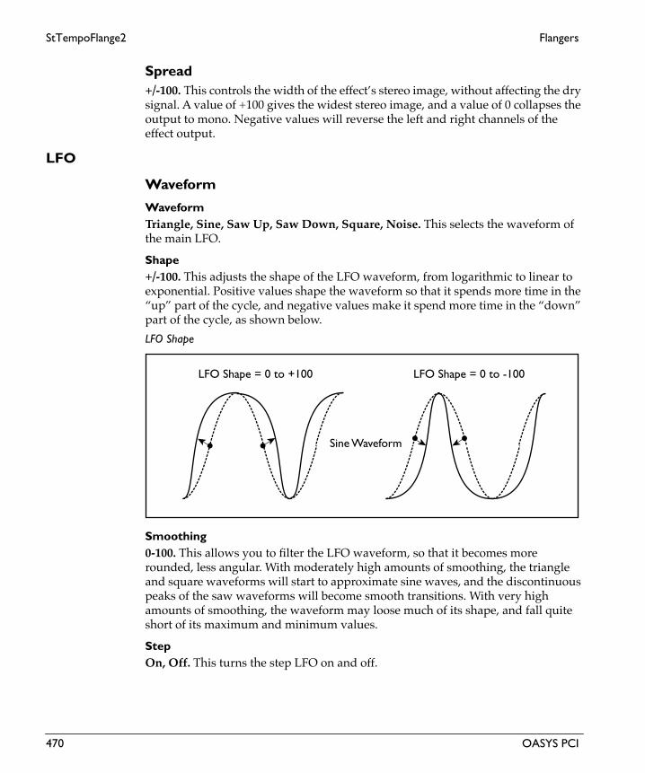
StTempoFlange2 Flangers
Eng
lish
Spread+/-100. This controls the width of the effect’s stereo image, without affecting the dry signal. A value of +100 gives the widest stereo image, and a value of 0 collapses the output to mono. Negative values will reverse the left and right channels of the effect output.
LFO
Waveform
WaveformTriangle, Sine, Saw Up, Saw Down, Square, Noise. This selects the waveform of the main LFO.
Shape+/-100. This adjusts the shape of the LFO waveform, from logarithmic to linear to exponential. Positive values shape the waveform so that it spends more time in the “up” part of the cycle, and negative values make it spend more time in the “down” part of the cycle, as shown below.
LFO Shape
Smoothing0-100. This allows you to filter the LFO waveform, so that it becomes more rounded, less angular. With moderately high amounts of smoothing, the triangle and square waveforms will start to approximate sine waves, and the discontinuous peaks of the saw waveforms will become smooth transitions. With very high amounts of smoothing, the waveform may loose much of its shape, and fall quite short of its maximum and minimum values.
StepOn, Off. This turns the step LFO on and off.
LFO Shape = 0 to +100 LFO Shape = 0 to -100
Sine Waveform
470 OASYS PCI

Flangers StTempoFlange2
LFO Waveforms and Phase
LFO ControlFrequency Knob, Manual Tempo, MIDI Tempo. The LFO speed can be controlled either by the Frequency knob (including the mod source), the Manual Tempo knob, or by MIDI Tempo (derived from MIDI clocks).
0˚ 90˚ 180˚-90˚-180˚ 0˚ 90˚ 180˚-90˚-180˚
+/-180˚ -90˚ 0˚90˚0˚
0˚ 90˚ 180˚-90˚-180˚ 0˚ 90˚ 180˚-90˚-180˚
+/-180˚ -90˚ 0˚90˚0˚
Triangle Sine
Saw DownSaw Up
NoiseSquare
OASYS PCI 471

StTempoFlange2 Flangers
Eng
lish
If this is set to Frequency Knob, then the LFO speed will be controlled by the settings in the Frequency section, including the mod source and amount.
If this is set to Manual Tempo, then the Manual Tempo knob will set the basic tempo, and the note value set in the Subdivisions menu will control the LFO speed.
If this is set to MIDI Tempo, then incoming MIDI Clocks will set the basic tempo, and the note value set in the Subdivisions menu will control the LFO speed.
Phase
Initial Phase+/-180. This sets the point in the waveform at which the LFO starts. Whenever the Phase Reset controller is received, the LFO will start from the Initial Phase point.
L/R Phase+/-180. This sets the phase difference between the LFOs for the right and left channels. Off-setting the phase between the two, as shown below, enhances the stereo effect–although with panning in particular, the two channels must contain fairly discrete material for this effect to be noticeable.
When using the LFO with tempo, the L/R Phase also creates a rhythmic offset between the left and right channels. For instance, a 1/4 note LFO with an L/R Phase of +180 creates alternating stereo 8th notes.
LFO Phase
Phase ResetList of Modulation Sources. This sets the MIDI controller which will reset the LFO’s phase to the Initial Phase point. You can use this to trigger the LFO from a MIDI sequencer, so that it always starts at the same point. This is especially useful
0° +90° +180°
0°–90°–180°
472 OASYS PCI
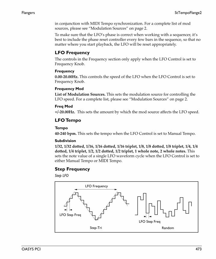
Flangers StTempoFlange2
in conjunction with MIDI Tempo synchronization. For a complete list of mod sources, please see “Modulation Sources” on page 2.
To make sure that the LFO’s phase is correct when working with a sequencer, it’s best to include the phase reset controller every few bars in the sequence, so that no matter where you start playback, the LFO will be reset appropriately.
LFO FrequencyThe controls in the Frequency section only apply when the LFO Control is set to Frequency Knob.
Frequency0.00-20.00Hz. This controls the speed of the LFO when the LFO Control is set to Frequency Knob.
Frequency ModList of Modulation Sources. This sets the modulation source for controlling the LFO speed. For a complete list, please see “Modulation Sources” on page 2.
Freq Mod+/-20.00Hz. This sets the amount by which the mod source affects the LFO speed.
LFO Tempo
Tempo40-240 bpm. This sets the tempo when the LFO Control is set to Manual Tempo.
Subdivision1/32, 1/32 dotted, 1/16, 1/16 dotted, 1/16 triplet, 1/8, 1/8 dotted, 1/8 triplet, 1/4, 1/4 dotted, 1/4 triplet, 1/2, 1/2 dotted, 1/2 triplet, 1 whole note, 2 whole notes. This sets the note value of a single LFO waveform cycle when the LFO Control is set to either Manual Tempo or MIDI Tempo.
Step FrequencyStep LFO
LFO Step Freq
LFO Frequency
LFO Step Freq
Step-Tri Random
OASYS PCI 473

StTempoFlange2 Flangers
Eng
lish
Step Freq0.00-80.00Hz. This controls the speed of the step LFO when the LFO Control is set to Frequency Knob.
Step Freq ModList of Modulation Sources. This sets the modulation source for controlling the speed of the step LFO. For a complete list, please see “Modulation Sources” on page 2.
Step Mod+/-80.00Hz. This sets the amount by which the mod source affects the speed of the step LFO.
Step ControlFrequency Knob, Manual Tempo, MIDI Tempo. The speed of the step LFO can be controlled either by the Frequency knob (including the mod source), the Manual Tempo knob, or by MIDI Tempo (derived from MIDI clocks).
If this is set to Frequency Knob, then the step LFO speed will be controlled by the settings in the Frequency section, including the mod source and amount.
If this is set to Manual Tempo, then the Manual Tempo knob will set the basic tempo, and the note value set in the Subdivisions menu will control the step LFO speed.
If this is set to MIDI Tempo, then incoming MIDI Clocks will set the basic tempo, and the note value set in the Subdivisions menu will control the step LFO speed.
Step Tempo
Manual Tempo40-240 bpm. This sets the tempo when the Step Control is set to Manual Tempo.
Subdivision1/32, 1/32 dotted, 1/16, 1/16 dotted, 1/16 triplet, 1/8, 1/8 dotted, 1/8 triplet, 1/4, 1/4 dotted, 1/4 triplet, 1/2, 1/2 dotted, 1/2 triplet, 1 whole note, 2 whole notes. This sets the note value of a single LFO waveform cycle when the Step Control is set to either Manual Tempo or MIDI Tempo.
Output
Wet/DryDry, 1:99-99:1, Wet. This sets the balance between the effect and the dry signal.
Wet/Dry ModList of Modulation Sources. This sets the modulation source for controlling the wet/dry mix. For a complete list, please see “Modulation Sources” on page 2.
474 OASYS PCI

Flangers StTempoFlange2
Mod Amount+/-100. This sets the amount by which the mod source affects the wet/dry mix.
Invert Wet PhaseOn, Off. This allows you to invert the phase of the wet signal.
OASYS PCI 475

Tempo Flanger Flangers
Eng
lish
Tempo FlangerThis is a mono-in, mono-out flanger with a complex, MIDI-syncable tempo LFO. Try modulating the LFO parameters, such as shape and smoothing, in real time.
For detailed instructions on working with MIDI-synced LFOs, see “MIDI Tempo LFOs” on page 5.
Input
SourceLeft, L + R. This is a mono-in, mono-out effect. Stereo signals are preserved in the dry mix at the output, but the effect itself has only a single, mono input.
When this is set to Left, only the left channel will be routed into the effect.
When this is set to L + R, the left and right channels will be summed together, and then routed into the effect.
Level-INF, -69.0 to 0.0dB. This sets the input level for the effect. It does not affect the dry signal.
Flanger
Delay0.0-50.0ms. This sets the center delay for the flanger.
Depth0-100. This controls the depth of LFO modulation.
Feedback+/-100. This controls the amount of feedback in the flanger. Higher feedback settings result in a more extreme sound.
Hi Damping0-100. This adjusts the amount of high frequency damping in the feedback loop.
LFO
Waveform
WaveformTriangle, Sine, Saw Up, Saw Down, Square, Sample & Hold. This selects the waveform of the LFO.
476 OASYS PCI

Flangers Tempo Flanger
LFO Waveforms and Phase
Shape+/-100. This adjusts the shape of the LFO waveform, from logarithmic to linear to exponential. Positive values shape the waveform so that it spends more time in the “up” part of the cycle, and negative values make it spend more time in the “down” part of the cycle, as shown below.
0˚ 90˚ 180˚-90˚-180˚ 0˚ 90˚ 180˚-90˚-180˚
+/-180˚ -90˚ 0˚90˚0˚
0˚ 90˚ 180˚-90˚-180˚ 0˚ 90˚ 180˚-90˚-180˚
+/-180˚ -90˚ 0˚90˚0˚
Triangle Sine
Saw DownSaw Up
Sample & HoldSquare
OASYS PCI 477

Tempo Flanger Flangers
Eng
lish
LFO Shape
Smoothing0-100. This allows you to filter the LFO waveform, so that it becomes more rounded, less angular. With moderately high amounts of smoothing, the triangle and square waveforms will start to approximate sine waves, and the discontinuous peaks of the saw waveforms will become smooth transitions. With very high amounts of smoothing, the waveform may loose much of its shape, and fall quite short of its maximum and minimum values.
LFO ControlFrequency Knob, Manual Tempo, MIDI Tempo. The LFO speed can be controlled either by the Frequency knob (including the mod source), the Manual Tempo knob, or by MIDI Tempo (derived from MIDI clocks).
If this is set to Frequency Knob, then the LFO speed will be controlled by the settings in the Frequency section, including the mod source and amount.
If this is set to Manual Tempo, then the Manual Tempo knob will set the basic tempo, and the note value set in the Subdivisions menu will control the LFO speed.
If this is set to MIDI Tempo, then incoming MIDI Clocks will set the basic tempo, and the note value set in the Subdivisions menu will control the LFO speed.
Phase
Initial PhaseThis sets the point in the waveform at which the LFO starts. Whenever the Phase Reset controller is received, the LFO will start from the Initial Phase point.
Phase ResetList of Modulation Sources. This sets the MIDI controller which will reset the LFO’s phase to the Initial Phase point. You can use this to trigger the LFO from a MIDI sequencer, so that it always starts at the same point. This is especially useful in conjunction with MIDI Tempo synchronization. For a complete list of mod sources, please see “Modulation Sources” on page 2.
LFO Shape = 0 to +100 LFO Shape = 0 to -100
Sine Waveform
478 OASYS PCI

Flangers Tempo Flanger
To make sure that the LFO’s phase is correct when working with a sequencer, it’s best to include the phase reset controller every few bars in the sequence, so that no matter where you start playback, the LFO will be reset appropriately.
FrequencyThe controls in the Frequency section only apply when the LFO Control is set to Frequency Knob.
Frequency0.00-20.00Hz. This controls the speed of the LFO when the LFO Control is set to Frequency Knob.
Frequency ModList of Modulation Sources. This sets the modulation source for controlling the LFO speed. For a complete list, please see “Modulation Sources” on page 2.
Mod Amount+/-20.00Hz. This sets the amount by which the mod source affects the LFO speed.
Tempo
Manual Tempo40-240 bpm. This sets the tempo when the LFO Control is set to Manual Tempo.
Subdivision1/32, 1/32 dotted, 1/16, 1/16 dotted, 1/16 triplet, 1/8, 1/8 dotted, 1/8 triplet, 1/4, 1/4 dotted, 1/4 triplet, 1/2, 1/2 dotted, 1/2 triplet, 1 whole note, 2 whole notes. This sets the note value of a single LFO waveform cycle when the LFO Control is set to either Manual Tempo or MIDI Tempo.
Output
ModeMono, Stereo. This controls whether the effect output is mono or simulated stereo.
When this is set to Mono, the output is in mono.
When this is set to Stereo, the output is simulated stereo, with the right effect output inverted. Note that this simulated stereo effect is not mono-compatible.
Wet/DryDry, 1:99-99:1, Wet. This sets the balance between the effect and the dry signal.
Wet/Dry ModList of Modulation Sources. This sets the modulation source for controlling the wet/dry mix. For a complete list, please see “Modulation Sources” on page 2.
OASYS PCI 479

Tempo Flanger Flangers
Eng
lish
Mod Amount+/-100. This sets the amount by which the mod source affects the wet/dry mix.
480 OASYS PCI

Modulations

Doppler Modulations
Eng
lish
DopplerThis effect simulates the Doppler effect, which causes perceived pitch to change as a sound-producing object moves by–such as a train passing while ringing its bell, or an ambulance driving by and sounding its siren.
You can also mix the effect output with the dry signal, to create an unusual chorus effect.
Input
Level-INF, -69.0 to 0.0dB. This sets the input level for the effect. It does not affect the dry signal.
Pan
Depth+/-100. This sets the depth of the panning effect–how widely the image swings between left and right.
Depth ModList of Modulation Sources. This sets the modulation source for controlling the panning depth. For a complete list, please see “Modulation Sources” on page 2.
Mod Amount+/-100. This sets the amount by which the mod source affects the panning depth.
Pitch
Depth0-100. This controls the depth of the doppler pitch shift.
Depth ModList of Modulation Sources. This sets the modulation source for controlling the pitch shift depth. For a complete list, please see “Modulation Sources” on page 2.
Mod Amount+/-100. This sets the amount by which the mod source affects the pitch shift.
LFO
ModeOne Shot, Loop. This determines whether the doppler effect will run continuously, or only when triggered.
482 OASYS PCI

Modulations Doppler
One Shot. The doppler will only act when triggered, and will then go through one cycle and stop.
Loop. The doppler effect will run continuously.
One Shot TriggerList of Modulation Sources. This sets the modulation source for triggering the doppler effect, when the Mode is set to One Shot. For a complete list, please see “Modulation Sources” on page 2.
Note RetriggerOn, Off. This determines the way that the doppler triggers when the One Shot Trigger is set to Note Gate or Note Gate + Sustain.
On. When this is on, the doppler will be triggered whenever a key is pressed.
Off. When this is off, the doppler will only be retriggered after all currently held notes have been released.
Frequency0.00-10.00Hz. This controls the speed of the doppler LFO.
Frequency ModList of Modulation Sources. This sets the modulation source for controlling the LFO speed. For a complete list, please see “Modulation Sources” on page 2.
Mod Amount+/-100. This sets the amount by which the mod source affects the LFO speed.
Output
Wet/DryDry, 1:99-99:1, Wet. This sets the balance between the effect and the dry signal.
Wet/Dry ModList of Modulation Sources. This sets the modulation source for controlling the wet/dry mix. For a complete list, please see “Modulation Sources” on page 2.
Mod Amount+/-100. This sets the amount by which the mod source affects the wet/dry mix.
OASYS PCI 483

Dual Resonator Modulations
Eng
lish
Dual ResonatorThis effect includes two independent resonators, which each cause the input signal to resonate at a specified pitch. For example, the resonators can add a unique character to a string sound by emphasizing certain harmonics, or add a pitched element to a drum loop.
Input
SourceLeft, L + R. This is a mono-in, stereo-out effect. Stereo signals are preserved in the dry mix at the output, but the effect itself has only a single, mono input.
When this is set to Left, only the left channel will be routed into the effect.
When this is set to L + R, the left and right channels will be summed together, and then routed into the effect.
Level-INF, -69.0 to 0.0dB. This sets the input level for the effect. It does not affect the dry signal.
ResonatorVoice1-2
Pitch (1-2)F#-1,99-G8,0. This sets the pitch of the resonator.
Resonance (1-2)+/-100. This controls the intensity of the resonance, when Control Mode is set to Manual. If the Resonance parameter has a negative value, harmonics will be changed, and resonance will occur at a pitch one octave below.
High Cut (1-2)0-100. This adjusts the amount of high frequency cut for the resonator.
Level (1-2)0-100. This sets the output level of the resonator.
Pan (1-2)0-100. This sets the stereo pan position of the resonator.
Resonance Mod / LFO
Control ModeManual, LFO, Mod Source. This determines how the resonator will be controlled.
484 OASYS PCI

Modulations Dual Resonator
Manual. The Resonance parameter sets the intensity of resonance.
Mod Source. The intensity of the resonance will be controlled directly from the MIDI mod source.
LFO. The intensity of the resonance will be controlled by the LFO.
Mod SourceList of Modulation Sources. This sets the modulation source for controlling the vowel shapes when the Control Source is set to Mod Source. For a complete list of modulators, please see “Modulation Sources” on page 2.
LFO Freq0.00-20.00Hz. This controls the speed of the LFO.
LFO Freq ModList of Modulation Sources. This sets the modulation source for controlling the LFO frequency. For a complete list, please see “Modulation Sources” on page 2.
Mod Amount+/-100. This sets the amount by which the mod source affects the LFO frequency.
Output
Wet/DryDry, 1:99-99:1, Wet. This sets the balance between the effect and the dry signal.
Wet/Dry ModList of Modulation Sources. This sets the modulation source for controlling the wet/dry mix. For a complete list, please see “Modulation Sources” on page 2.
Mod Amount+/-100. This sets the amount by which the mod source affects the wet/dry mix.
OASYS PCI 485

Resonator Modulations
Eng
lish
ResonatorThis effect causes the input signal to resonate at a specified pitch. For example, the Resonator can add a unique character to a string sound by emphasizing certain harmonics, or add a pitched element to a drum loop. You can control the resonance intensity via an LFO.
Input
SourceLeft, L + R. This is a mono-in, mono-out effect. Stereo signals are preserved in the dry mix at the output, but the effect itself has only a single, mono input.
When this is set to Left, only the left channel will be routed into the effect.
When this is set to L + R, the left and right channels will be summed together, and then routed into the effect.
Level-INF, -69.0 to 0.0dB. This sets the input level for the effect. It does not affect the dry signal.
Resonator
Control SourceManual, LFO. This determines how the resonator will be controlled.
Manual. The Resonance parameter sets the intensity of resonance.
LFO. The intensity of the resonance will be controlled by the LFO.
PitchF#-1,99-G8,0. This sets the pitch of the resonator.
Resonance+/-100. This controls the intensity of the resonance, when Control Mode is set to Manual. If the Resonance parameter has a negative value, harmonics will be changed, and resonance will occur at a pitch one octave below.
High Damp0-100. This adjusts the amount of high frequency damping for the resonator.
LFO
Frequency0.00-20.00Hz. This controls the speed of the LFO.
486 OASYS PCI

Modulations Resonator
Frequency ModList of Modulation Sources. This sets the modulation source for controlling the LFO frequency. For a complete list, please see “Modulation Sources” on page 2.
Mod Amount+/-100. This sets the amount by which the mod source affects the LFO frequency.
Output
ModeMono, Stereo. This controls whether the effect output is mono or simulated stereo.
When this is set to Mono, the output is in mono.
When this is set to Stereo, the output is simulated stereo, with the right effect output inverted. Note that this simulated stereo effect is not mono-compatible.
Wet/DryDry, 1:99-99:1, Wet. This sets the balance between the effect and the dry signal.
Wet/Dry ModList of Modulation Sources. This sets the modulation source for controlling the wet/dry mix. For a complete list, please see “Modulation Sources” on page 2.
Mod Amount+/-100. This sets the amount by which the mod source affects the wet/dry mix.
OASYS PCI 487

Ring Modulator Modulations
Eng
lish
Ring ModulatorThis effect creates a metallic sound by routing the input signal to an oscillator. You can create very extreme effects by modulating the oscillator using an LFO or MIDI modulation. Since the oscillator frequency can match the note number, you can create a ring modulation effect that follows the scale.
Input
SourceLeft, L + R. This is a mono-in, stereo-out effect. Stereo signals are preserved in the dry mix at the output, but the effect itself has only a single, mono input.
When this is set to Left, only the left channel will be routed into the effect.
When this is set to L + R, the left and right channels will be summed together, and then routed into the effect.
Level-INF, -69.0 to 0.0dB. This sets the input level for the effect. It does not affect the dry signal.
Ring Mod
Pre LPF0-100. This adjusts the cutoff of the pre-effect lowpass filter.
Osc ModeFixed, Note. This sets the way that the oscillator will be controlled.
Fixed. The oscillator will use the frequency set under the Fixed section.
Note. The oscillator will follow incoming MIDI notes.
Fixed
Fixed Freq0-12000Hz. This sets the basic pitch of the oscillator when the Osc Mode is set to Fixed.
Fixed Freq ModList of Modulation Sources. This sets the modulation source for controlling the Fixed frequency. For a complete list, please see “Modulation Sources” on page 2.
Mod Amount+/-12000. This sets the amount by which the mod source affects the oscillator frequency.
488 OASYS PCI

Modulations Ring Modulator
Note
Note Offset+/-48. This allows you to offset the pitch from the received MIDI note numbers, in semitones.
Note Fine+/-100. This allows you to fine-tune the resonators, in cents (1/100 of a semitone).
Note Offset ModList of Modulation Sources. This sets the modulation source for controlling the note offset and fine tune. For a complete list, please see “Modulation Sources” on page 2.
Mod Amount+/-48. This sets the amount by which the mod source affects the note offset.
Fine Amount+/-100. This sets the amount by which the mod source affects the fine tune.
LFO
LFO Depth0-100. This controls the amount of LFO modulation.
LFO Depth ModList of Modulation Sources. This sets the modulation source for controlling the LFO depth. For a complete list, please see “Modulation Sources” on page 2.
Mod Amount+/-100. This sets the amount by which the mod source affects the LFO depth.
Frequency0.00-20.00Hz. This controls the speed of the LFO.
Frequency ModList of Modulation Sources. This sets the modulation source for controlling the LFO frequency. For a complete list, please see “Modulation Sources” on page 2.
Mod Amount+/-20.0Hz. This sets the amount by which the mod source affects the LFO frequency.
OASYS PCI 489

Ring Modulator Modulations
Eng
lish
Output
Wet/DryDry, 1:99-99:1, Wet. This sets the balance between the effect and the dry signal.
Wet/Dry ModList of Modulation Sources. This sets the modulation source for controlling the wet/dry mix. For a complete list, please see “Modulation Sources” on page 2.
Mod Amount+/-100. This sets the amount by which the mod source affects the wet/dry mix.
490 OASYS PCI

Modulations St Vibrato AF
St Vibrato AFThis is a stereo-in, stereo-out vibrato effect, with a triggered auto fade envelope. The envelope can modulate LFO amount to vibrato, LFO amount to filter cutoff, and LFO frequency.
Input
Level-INF, -69.0 to 0.0dB. This sets the input level for the effect. It does not affect the dry signal.
Auto Fade
Trigger SourceList of Modulation Sources. This sets the modulation source for triggering the auto fade envelope. For a complete list, please see “Modulation Sources” on page 2.
Note RetriggerOn, Off. This determines the way that the auto fade envelope triggers when the Trigger Source is set to Note Gate or Note Gate + Sustain.
On. When this is on, the envelope will be triggered whenever a key is pressed.
Off. When this is off, the envelope will only be retriggered after all currently held notes have been released.
Rate0-100. This sets the attack rate of the auto fade envelope.
Auto Fade
Note On All Notes Off
Fade-In Rate
Note Gate
AUTOFADE
OASYS PCI 491

St Vibrato AF Modulations
Eng
lish
Stereo Vibrato
Depth0-100. This controls the depth of the vibrato.
Depth ModList of Modulation Sources. This sets the modulation source for controlling the vibrato depth. For a complete list, please see “Modulation Sources” on page 2.
Mod Amount+/-100. This sets the amount by which the mod source affects the vibrato depth.
Depth Auto FadeOn, Off. This enables modulation of depth via the auto fade envelope.
Filter
Lowpass FilterOn, Off. This enables and disables the built-in lowpass filter.
Cutoff0-100. This sets the cutoff frequency of the lowpass filter.
LFO Depth+/-100. This sets the amount of LFO modulation for the filter.
LFO Depth ModList of Modulation Sources. This sets the modulation source for controlling the filter LFO depth. For a complete list, please see “Modulation Sources” on page 2.
Mod Amount+/-100. This sets the amount by which the mod source affects the filter LFO depth.
Depth Auto FadeOn, Off. This enables modulation of filter LFO depth via the auto fade envelope.
LFO
WaveformTriangle, Sine. This selects the waveform for the LFO.
Shape+/-100. This adjusts the shape of the LFO waveform, from logarithmic to linear to exponential. Positive values shape the waveform so that it spends more time in the
492 OASYS PCI

Modulations St Vibrato AF
“up” part of the cycle, and negative values make it spend more time in the “down” part of the cycle, as shown below.
LFO Shape
Freq0.00-20.00Hz. This controls the speed of the LFO.
Freq ModList of Modulation Sources. This sets the modulation source for controlling the LFO frequency. For a complete list, please see “Modulation Sources” on page 2.
Mod Amount+/-20.00Hz. This sets the amount by which the mod source affects the LFO frequency.
Freq Auto FadeOn, Off. This enables modulation of frequency via the auto fade envelope.
Output
Wet/DryDry, 1:99-99:1, Wet. This sets the balance between the effect and the dry signal.
Wet/Dry ModList of Modulation Sources. This sets the modulation source for controlling the wet/dry mix. For a complete list, please see “Modulation Sources” on page 2.
Mod Amount+/-100. This sets the amount by which the mod source affects the wet/dry mix.
LFO Shape = 0 to +100 LFO Shape = 0 to -100
Sine Waveform
OASYS PCI 493

St Vibrato Modulations
Eng
lish
St VibratoThis is a stereo-in, stereo-out vibrato effect.
Input
Level-INF, -69.0 to 0.0dB. This sets the input level for the effect. It does not affect the dry signal.
Stereo Vibrato
Depth0-100. This controls the depth of the vibrato.
Depth ModList of Modulation Sources. This sets the modulation source for controlling the vibrato depth. For a complete list, please see “Modulation Sources” on page 2.
Mod Amount+/-100. This sets the amount by which the mod source affects the vibrato depth.
Filter
Lowpass FilterOn, Off. This enables and disables the built-in lowpass filter.
Cutoff0-100. This sets the cutoff frequency of the lowpass filter.
LFO Depth+/-100. This sets the amount of LFO modulation for the filter.
LFO Depth ModList of Modulation Sources. This sets the modulation source for controlling the filter LFO depth. For a complete list, please see “Modulation Sources” on page 2.
Mod Amount+/-100. This sets the amount by which the mod source affects the filter LFO depth.
LFO
WaveformTriangle, Sine. This selects the waveform for the LFO.
494 OASYS PCI

Modulations St Vibrato
Shape+/-100. This adjusts the shape of the LFO waveform, from logarithmic to linear to exponential. Positive values shape the waveform so that it spends more time in the “up” part of the cycle, and negative values make it spend more time in the “down” part of the cycle, as shown below.
LFO Shape
Freq0.00-20.00Hz. This controls the speed of the LFO.
Freq ModList of Modulation Sources. This sets the modulation source for controlling the LFO frequency. For a complete list, please see “Modulation Sources” on page 2.
Mod Amount+/-20.00Hz. This sets the amount by which the mod source affects the LFO frequency.
Output
Wet/DryDry, 1:99-99:1, Wet. This sets the balance between the effect and the dry signal.
Wet/Dry ModList of Modulation Sources. This sets the modulation source for controlling the wet/dry mix. For a complete list, please see “Modulation Sources” on page 2.
Mod Amount+/-100. This sets the amount by which the mod source affects the wet/dry mix.
LFO Shape = 0 to +100 LFO Shape = 0 to -100
Sine Waveform
OASYS PCI 495

Vibrato AF Modulations
Eng
lish
Vibrato AFThis is a mono-in, stereo-out vibrato effect, with a triggered auto fade envelope. The envelope can modulate LFO amount to vibrato, LFO amount to filter cutoff, and LFO frequency.
Input
SourceLeft, L + R. This is a mono-in, stereo-out effect. Stereo signals are preserved in the dry mix at the output, but the effect itself has only a single, mono input.
When this is set to Left, only the left channel will be routed into the effect.
When this is set to L + R, the left and right channels will be summed together, and then routed into the effect.
Level-INF, -69.0 to 0.0dB. This sets the input level for the effect. It does not affect the dry signal.
Auto Fade
Trigger SourceList of Modulation Sources. This sets the modulation source for triggering the auto fade envelope. For a complete list, please see “Modulation Sources” on page 2.
Note RetriggerOn, Off. This determines the way that the auto fade envelope triggers when the Trigger Source is set to Note Gate or Note Gate + Sustain.
On. When this is on, the envelope will be triggered whenever a key is pressed.
Off. When this is off, the envelope will only be retriggered after all currently held notes have been released.
Rate0-100. This sets the attack rate of the auto fade envelope.
496 OASYS PCI

Modulations Vibrato AF
Auto Fade
Vibrato
Depth0-100. This controls the depth of the vibrato.
Depth ModList of Modulation Sources. This sets the modulation source for controlling the vibrato depth. For a complete list, please see “Modulation Sources” on page 2.
Mod Amount+/-100. This sets the amount by which the mod source affects the vibrato depth.
Depth Auto FadeOn, Off. This enables modulation of depth via the auto fade envelope.
Filter
Lowpass FilterOn, Off. This enables and disables the built-in lowpass filter.
Cutoff0-100. This sets the cutoff frequency of the lowpass filter.
LFO Depth+/-100. This sets the amount of LFO modulation for the filter.
Note On All Notes Off
Fade-In Rate
Note Gate
AUTOFADE
OASYS PCI 497

Vibrato AF Modulations
Eng
lish
LFO Depth ModList of Modulation Sources. This sets the modulation source for controlling the filter LFO depth. For a complete list, please see “Modulation Sources” on page 2.
Mod Amount+/-100. This sets the amount by which the mod source affects the filter LFO depth.
Depth Auto FadeOn, Off. This enables modulation of filter LFO depth via the auto fade envelope.
LFO
WaveformTriangle, Sine. This selects the waveform for the LFO.
Shape+/-100. This adjusts the shape of the LFO waveform, from logarithmic to linear to exponential. Positive values shape the waveform so that it spends more time in the “up” part of the cycle, and negative values make it spend more time in the “down” part of the cycle, as shown below.
LFO Shape
Freq0.00-20.00Hz. This controls the speed of the LFO.
Freq ModList of Modulation Sources. This sets the modulation source for controlling the LFO frequency. For a complete list, please see “Modulation Sources” on page 2.
Mod Amount+/-20.00Hz. This sets the amount by which the mod source affects the LFO frequency.
LFO Shape = 0 to +100 LFO Shape = 0 to -100
Sine Waveform
498 OASYS PCI

Modulations Vibrato AF
Freq Auto FadeOn, Off. This enables modulation of frequency via the auto fade envelope.
Output
Wet/DryDry, 1:99-99:1, Wet. This sets the balance between the effect and the dry signal.
Wet/Dry ModList of Modulation Sources. This sets the modulation source for controlling the wet/dry mix. For a complete list, please see “Modulation Sources” on page 2.
Mod Amount+/-100. This sets the amount by which the mod source affects the wet/dry mix.
OASYS PCI 499

Vibrato Modulations
Eng
lish
VibratoThis is a mono-in, stereo-out vibrato effect.
Input
SourceLeft, L + R. This is a mono-in, stereo-out effect. Stereo signals are preserved in the dry mix at the output, but the effect itself has only a single, mono input.
When this is set to Left, only the left channel will be routed into the effect.
When this is set to L + R, the left and right channels will be summed together, and then routed into the effect.
Level-INF, -69.0 to 0.0dB. This sets the input level for the effect. It does not affect the dry signal.
Vibrato
Depth0-100. This controls the depth of the vibrato.
Depth ModList of Modulation Sources. This sets the modulation source for controlling the vibrato depth. For a complete list, please see “Modulation Sources” on page 2.
Mod Amount+/-100. This sets the amount by which the mod source affects the vibrato depth.
Filter
Lowpass FilterOn, Off. This enables and disables the built-in lowpass filter.
Cutoff0-100. This sets the cutoff frequency of the lowpass filter.
LFO Depth+/-100. This sets the amount of LFO modulation for the filter.
LFO Depth ModList of Modulation Sources. This sets the modulation source for controlling the filter LFO depth. For a complete list, please see “Modulation Sources” on page 2.
500 OASYS PCI

Modulations Vibrato
Mod Amount+/-100. This sets the amount by which the mod source affects the filter LFO depth.
LFO
WaveformTriangle, Sine. This selects the waveform for the LFO.
Shape+/-100. This adjusts the shape of the LFO waveform, from logarithmic to linear to exponential. Positive values shape the waveform so that it spends more time in the “up” part of the cycle, and negative values make it spend more time in the “down” part of the cycle, as shown below.
LFO Shape
Freq0.00-20.00Hz. This controls the speed of the LFO.
Freq ModList of Modulation Sources. This sets the modulation source for controlling the LFO frequency. For a complete list, please see “Modulation Sources” on page 2.
Mod Amount+/-20.00Hz. This sets the amount by which the mod source affects the LFO frequency.
Output
Wet/DryDry, 1:99-99:1, Wet. This sets the balance between the effect and the dry signal.
LFO Shape = 0 to +100 LFO Shape = 0 to -100
Sine Waveform
OASYS PCI 501
Vibrato Modulations
Eng
lish
Wet/Dry ModList of Modulation Sources. This sets the modulation source for controlling the wet/dry mix. For a complete list, please see “Modulation Sources” on page 2.
Mod Amount+/-100. This sets the amount by which the mod source affects the wet/dry mix.
502 OASYS PCI

Organ FX

Rotary Speaker Organ FX
Eng
lish
Rotary SpeakerThis is the rotary speaker model from the Korg G4. It includes independent speed and acceleration for the horn and rotor, parameterized mic placement, and overdrive and speaker simulations.
Input
SourceLeft, L + R. This is a mono-in, stereo-out effect. Stereo signals are preserved in the dry mix at the output, but the effect itself has only a single, mono input.
When this is set to Left, only the left channel will be routed into the effect.
When this is set to L + R, the left and right channels will be summed together, and then routed into the effect.
Level-INF, -69.0 to 0.0dB. This sets the input level for the effect. It does not affect the dry signal.
Overdrive/Speaker
OverdriveOff, On. This turns the overdrive on and off.
On/Off SourceList of Modulation Sources. This sets the modulation source for controlling the overdrive on/off switch. For a complete list of mod sources, please see “Modulation Sources” on page 2.
On/Off SWMomentary, Toggle. This determines the behavior of the overdrive on/off modulator.
Momentary. The the on/off state is changed only as long as the switch is on. When the switch is released, it returns to the previous state.
Toggle. The switch turns the overdrive on and off alternately. Switching once turns it on; switching again turns it off.
Drive-40.0-0.0dB. This sets the amount of distortion.
Tone0.0-18.0dB. This adjusts the brightness of the overdrive.
504 OASYS PCI

Organ FX Rotary Speaker
Out Level0-100. This controls the volume level coming out of the overdrive section.
Speaker Sim.Off, On. This turns the speaker simulation on and off. The speaker simulation gives the overdrive a rounder tone.
Rotary On/Off Modulation
Initial ModeRotate, Stop. This sets whether the speaker will begin moving immediately when the sound is loaded, or whether it will be stopped until switched on.
Mod SourceList of Modulation Sources. This sets the modulation source for controlling the rotary on/off switch. For a complete list of mod sources, please see “Modulation Sources” on page 2.
Mode SWMomentary, Toggle. This determines the behavior of the rotary on/off switch.
Momentary. The the on/off state is changed only as long as the switch is on. When the switch is released, it returns to the previous state.
Toggle. The switch turns the rotary speaker on and off alternately. Switching once turns it on; switching again turns it off.
Rotary Speed Modulation
Initial SpeedSlow, Fast. This sets the initial speed of the rotary speaker.
Mod SourceList of Modulation Sources. This selects the modulation source for controlling the slow/fast speed switch. For a complete list of mod sources, please see “Modulation Sources” on page 2.
Speed SWMomentary, Toggle. This determines the behavior of the slow/fast speed switch.
Momentary. The the slow/fast state is changed only as long as the switch is on. When the switch is released, it returns to the previous state.
Toggle. The switch changes the speeds alternately. Switching once changes it to fast; switching again changes it back to slow.
OASYS PCI 505
Rotary Speaker Organ FX
Eng
lish
Microphone Placement
Horn Distance0-100. This controls the distance of the mic from the horn (the high-frequency part of the rotary speaker).
Horn Spread0-100. This determines the stereo spread of the signal from the horn.
Rotor Distance0-100. This sets the distance of the mic from the rotor (the low-frequency part of the rotary speaker)
Rotor Spread0-100. This controls the stereo spread of the signal from the rotor.
Rotary Speaker
Horn Speed+/-100. This adjusts the speed of the horn (the high-frequency part of the rotary speaker).
Horn Acceleration0-100. This controls how long it takes for the horn to speed up and slow down, when switched from fast to slow.
Rotor Speed+/-100. This adjusts the speed of the rotor (the low-frequency part of the rotary speaker).
Rotor Acceleration0-100. This sets how long it takes for the rotor to speed up and slow down, when switched from fast to slow.
Horn/Rotor Balance0-100. This is the volume balance between the horn and the rotor.
Output
Wet/DryDry, 1:99-99:1, Wet. This sets the balance between the effect and the dry signal.
Wet/Dry ModList of Modulation Sources. This sets the modulation source for controlling the wet/dry mix. For a complete list, please see “Modulation Sources” on page 2.
506 OASYS PCI

Organ FX Rotary Speaker
Mod Amount+/-100. This sets the amount by which the mod source affects the wet/dry mix.
OASYS PCI 507

Vibrato Chorus Organ FX
Eng
lish
Vibrato ChorusThis is a physical model of the tonewheel organ’s classic vibrato-chorus effect.
Input
SourceLeft, L + R. This is a mono-in, stereo-out effect. Stereo signals are preserved in the dry mix at the output, but the effect itself has only a single, mono input.
When this is set to Left, only the left channel will be routed into the effect.
When this is set to L + R, the left and right channels will be summed together, and then routed into the effect.
Level-INF, -69.0 to 0.0dB. This sets the input level for the effect. It does not affect the dry signal.
Vibrato Chorus
Cutoff0-100. The chorus is made from a series of lowpass filters; this is the cutoff frequency of those filters.
LFO Rate0.10-20.00Hz. This sets the speed of the LFO. In the original effect, the frequency was fixed at 6.9Hz.
LFO Amt0-100. This controls the amount of LFO modulation.
LFO Offset0-100. This sets the tap on which the LFO is centered.
Output
Wet+/-100. This controls the output level of the wet signal. Negative values invert the phase.
Dry0-100. This controls the output level of the dry signal.
508 OASYS PCI

Other Effects
Decimator Other Effects
Eng
lish
DecimatorThe Decimator downsamples incoming audio to create a gritty, rough effect. You can modulate the sample rate via MIDI controllers.
Input
SourceLeft, L + R. This is a mono-in, mono-out effect. Stereo signals are preserved in the dry mix at the output, but the effect itself has only a single, mono input.
When this is set to Left, only the left channel will be routed into the effect.
When this is set to L + R, the left and right channels will be summed together, and then routed into the effect.
Level-INF, -69.0 to 0.0dB. This sets the input level for the effect. It does not affect the dry signal.
Decimator
Pre LPFOn, Off. This turns the pre-effect lowpass filter on and off. The lowpass can be used to smooth out some of the more extreme effects of the sample rate conversion!
Sample Rate1000-24000Hz. This converts the sample rate of the audio, downsampling to create a gritty-sounding effect.
Sample Rate ModList of Modulation Sources. This sets the modulation source for controlling the sample rate. For a complete list, please see “Modulation Sources” on page 2.
Mod Amount+/-24000Hz. This sets the amount by which the mod source affects the sample rate
Damping0-100. This sets the amount of high frequency damping.
Output
Wet/DryDry, 1:99-99:1, Wet. This sets the balance between the effect and the dry signal.
510 OASYS PCI

Other Effects Decimator
Wet/Dry ModList of Modulation Sources. This sets the modulation source for controlling the wet/dry mix. For a complete list, please see “Modulation Sources” on page 2.
Mod Amount+/-100. This sets the amount by which the mod source affects the wet/dry mix.
OASYS PCI 511

LR Gain Other Effects
Eng
lish
LR GainThis is a very simple effect which provides +/-18.1 dB of gain separately adjustable for the left and right channels.
LR Gain
Left Volume+/-18.1dB. This is the volume boost or cut for the left channel.
Right Volume+/-18.1dB. This is the volume boost or cut for the right channel.
512 OASYS PCI

Other Effects Piano Body
Piano BodyThis effect models the resonance of the piano sound board, and also models the sympathetic resonance of unplayed strings, as occurs when you press the damper pedal. It is intended to be applied to acoustic piano sounds.
Input
SourceLeft, L + R. This is a mono-in, stereo-out effect. Stereo signals are preserved in the dry mix at the output, but the effect itself has only a single, mono input.
When this is set to Left, only the left channel will be routed into the effect.
When this is set to L + R, the left and right channels will be summed together, and then routed into the effect.
Level-INF, -69.0 to 0.0dB. This sets the input level for the effect. It does not affect the dry signal.
Piano Body/Damper
Damper SourceList of Modulation Sources. This sets the modulation source for controlling the damper pedal. For a complete list, please see “Modulation Sources” on page 2.
SoundBoard Depth0-100. This controls the intensity of the sound board’s resonance.
Damper Depth0-100. This parameter adjusts the intensity of the sympathetic resonance of unplayed strings created when the damper pedal is pressed.
Tone0-100. This adjusts the tonal quality of the piano soundboard.
Mid EQ+/-18.1dB. This adjusts the mid range of the tonal quality.
Tune+/-50. Since this effect simulates the resonance of the strings, the sound varies depending on the pitch. If you have changed the tuning of the input signal (for instance, detuning using a Master Tune parameter), adjust the Tune parameter to match.
OASYS PCI 513

Piano Body Other Effects
Eng
lish
Output
Wet/DryDry, 1:99-99:1, Wet. This sets the balance between the effect and the dry signal.
Wet/Dry ModList of Modulation Sources. This sets the modulation source for controlling the wet/dry mix. For a complete list, please see “Modulation Sources” on page 2.
Mod Amount+/-100. This sets the amount by which the mod source affects the wet/dry mix.
514 OASYS PCI

Other Effects St Decimator
St DecimatorThis is a stereo-input, stereo-output Decimator. It downsamples incoming audio to create a gritty, rough effect. You can modulate the sample rate via MIDI controllers.
Input
Level-INF, -69.0 to 0.0dB. This sets the input level for the effect. It does not affect the dry signal.
Decimator
Pre LPFOn, Off. This turns the pre-effect lowpass filter on and off. The lowpass can be used to smooth out some of the more extreme effects of the sample rate conversion!
Sample Rate1000-24000Hz. This converts the sample rate of the audio, downsampling to create a gritty-sounding effect.
Sample Rate ModList of Modulation Sources. This sets the modulation source for controlling the sample rate. For a complete list, please see “Modulation Sources” on page 2.
Mod Amount+/-24000Hz. This sets the amount by which the mod source affects the sample rate
Damping0-100. This sets the amount of high frequency damping.
Output
Wet/DryDry, 1:99-99:1, Wet. This sets the balance between the effect and the dry signal.
Wet/Dry ModList of Modulation Sources. This sets the modulation source for controlling the wet/dry mix. For a complete list, please see “Modulation Sources” on page 2.
Mod Amount+/-100. This sets the amount by which the mod source affects the wet/dry mix.
OASYS PCI 515

St Gain Other Effects
Eng
lish
St GainThis is a very simple effect which provides +/-18.1 dB of boost or cut for a stereo signal.
Stereo Gain
Volume+/-18.1dB. This is the volume boost or cut for the stereo signal.
516 OASYS PCI

Other Effects Sub Oscillator
Sub OscillatorThis effect adds very low frequencies to the input signal. It’s useful when creating a roaring drum sound or emphasizing powerful, low range harmonics. You can also adjust the oscillator frequency to match a particular note number, for use as an octaver.
Input
SourceLeft, L + R. This is a mono-in, stereo-out effect. Stereo signals are preserved in the dry mix at the output, but the effect itself has only a single, mono input.
When this is set to Left, only the left channel will be routed into the effect.
When this is set to L + R, the left and right channels will be summed together, and then routed into the effect.
Level-INF, -69.0 to 0.0dB. This sets the input level for the effect. It does not affect the dry signal.
Envelope
Envelope SelectL/R Mix, L Only, R Only. This selects the input which will drive the envelope follower.
Pre LPF0-100. This parameter sets the upper limit of the sub oscillator’s frequency range. Only sounds below this frequency will be supplemented with low harmonics. Adjust this parameter if you do not want to add low harmonics to higher frequencies. For example, you can create a good effect by adding very low harmonics only to the bass drum sound, not to the snare sound.
Sens0-100. This sets the input sensitivity of the envelope follower.
Shape+/-100. Sets the curve of the envelope follower, as shown below.
OASYS PCI 517

Sub Oscillator Other Effects
Eng
lish
Envelope Shape
Sub Oscillator
ModeFixed, Note. This sets the way that the oscillator will be controlled.
Fixed. The oscillator will use the Fixed Frequency, as set below.
Note. The oscillator will follow incoming MIDI notes.
Note Offset-48-0. This allows you to offset the pitch from the received MIDI note numbers, in semitones.
Note Fine+/-100. This allows you to fine-tune the resonators, in cents (1/100 of a semitone).
Fixed Freq20.00-200.00Hz. This sets the basic pitch of the oscillator when the Mode is set to Fixed.
Fixed Freq ModList of Modulation Sources. This sets the modulation source for controlling the Fixed frequency. For a complete list, please see “Modulation Sources” on page 2.
Mod Amount+/-80Hz. This sets the amount by which the mod source affects the oscillator frequency.
Level
Time
0 to +100
0 to -100
OriginalEnvelope
518 OASYS PCI
Other Effects Sub Oscillator
Output
Wet/DryDry, 1:99-99:1, Wet. This sets the balance between the effect and the dry signal.
OASYS PCI 519

The Producer Other Effects
Eng
lish
The ProducerThe Producer is a revolutionary new effect that makes non-musicians and musicians happy at the same time. It’s designed to give A&R reps, managers, lawyers, and meddling parents the artistic control they’ve always coveted, while leaving musicians free to create. With this effect, others can modify your sound, fix your vocals, smooth your jazz, adjust your demographic appeal, and generally mess with your artistic vision to degrees not previously possible.
Or so they think! In actual fact, The Producer is merely a disguised straight-through effect. In other words, it does nothing. Simply hand over the controls of The Producer to the helpful outsider, and he or she can carefully and merrily adjust the knobs and settings, all the while thinking that they’re exerting an exacting effect on your music. As proof, they need merely observe the VU meters dancing in the control panel. Meanwhile, you can concentrate on making your music, your way. It’s a win-win situation.
Or maybe this effect really does change the audio. You be the judge! And listen carefully...
Genre Mixer
R&B+/-100. Increases or decreases the rhythm and blues feel of a signal.
Country+/-100. Increases or decreases the country feel of a signal.
Rock+/-100. Increases or decreases the rock feel of a signal.
Hip Hop+/-100. Increases or decreases the hip hop feel of a signal.
Rap+/-100. Increases or decreases the rap feel of a signal.
Lyric Transmogrifier
Envelope SelectBarney Filter. Should be activated when the lead vocalist sounds a little too much like a character from children’s television.
Leave As-Is. Don’t change the lyrics and vocals, no matter how bad they are.
Incomprehensible Gibberish. Converts the vocals to mumbled, muted, and yet mysteriously poetic ramblings, just outside the range of comprehension.
520 OASYS PCI

Other Effects The Producer
Rappify. Adds attitude and street cred. (West Coast and East Coast options may be added in the future.)
Target Demographic
Future Adult+/-100. Increases or decreases the demographic appeal of a signal to listeners under the age of 18.
Contemporary Adult+/-100. Increases or decreases a signal’s demographic appeal to listeners over the age of 18.
Former Adult+/-100. Increases or decreases a signal’s demographic appeal to listeners who are dead.
Desuck0-100. The most important knob of this effect. Although there are limits to its powers, in general this knob can be used to improve a signal that sucks.
OASYS PCI 521

Pan & Tremolo

Pan & Tremolo Shimmer
ShimmerThis is a stereo-in, stereo-out tremolo effect, in which both the depth and frequency of the volume modulation may be controlled by an envelope follower driven by the input level.
Input
Level-INF, -69.0 to 0.0dB. This sets the input level for the effect. It does not affect the dry signal.
Shimmer
Depth0-100. This sets the depth of the tremolo effect.
Env Amount+/-100. This controls the amount by which the envelope follower will modulate the tremolo depth.
Shimmer
LFO
WaveformTriangle, Sine. This selects the waveform for the LFO.
Level
Time
Dry Envelope
LFO Frequency = 8.0HzEnvelope Amount = -7.0HzDepth = 100
OASYS PCI 523

Shimmer Pan & Tremolo
Eng
lish
Shape+/-100. This adjusts the shape of the LFO waveform. Positive values shape the curve so that it spends more time in the “up” part of the cycle, and negative values make it spend more time in the “down” part of the cycle, as shown below.
LFO Shape
Phase+/-100. This adjusts the difference between the phases of the left and right LFOs.
Frequency0.00-20.00Hz. This sets the frequency of the LFOs.
Env Amount+/-20.00Hz. This controls the amount by which the envelope follower will modulate the LFO frequency.
Envelope
Envelope SelectL/R Mix, L Only, R Only. This selects the input which will drive the envelope follower.
Sens0-100. This sets the input sensitivity of the envelope follower.
Shape+/-100. Sets the curve of the envelope follower, as shown below.
LFO Shape = 0 to +100 LFO Shape = 0 to -100
Sine Waveform
524 OASYS PCI

Pan & Tremolo Shimmer
Envelope Shape
Output
Wet/DryDry, 1:99-99:1, Wet. This sets the balance between the effect and the dry signal.
Wet/Dry ModList of Modulation Sources. This sets the modulation source for controlling the wet/dry mix. For a complete list, please see “Modulation Sources” on page 2.
Mod Amount+/-100. This sets the amount by which the mod source affects the wet/dry mix.
Level
Time
0 to +100
0 to -100
OriginalEnvelope
OASYS PCI 525

St Auto Pan Pan & Tremolo
Eng
lish
St Auto PanThis is a stereo-in, stereo-out auto-panner.
Input
Level-INF, -69.0 to 0.0dB. This sets the input level for the effect. It does not affect the dry signal.
LFO
WaveformTriangle, Sine. This selects the LFO shape.
Shape+/-100. This adjusts the shape of the LFO waveform, from logarithmic to linear to exponential. Positive values shape the waveform so that it spends more time in the “up” part of the cycle, and negative values make it spend more time in the “down” part of the cycle, as shown below.
LFO Shape
Phase+/-180. This sets the phase difference between the LFOs for the right and left channels. When you change the value gradually from 0, the sounds from the left and right channels will chase each other around. If you set the parameter to +180 or –180, the sounds from each channel will cross over each other.
You need to input different sounds to each channel in order for this parameter to be effective.
LFO Shape = 0 to +100 LFO Shape = 0 to -100
Sine Waveform
526 OASYS PCI
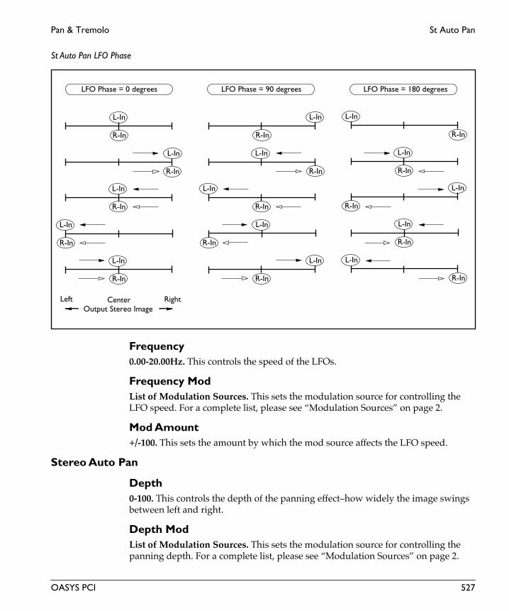
Pan & Tremolo St Auto Pan
St Auto Pan LFO Phase
Frequency0.00-20.00Hz. This controls the speed of the LFOs.
Frequency ModList of Modulation Sources. This sets the modulation source for controlling the LFO speed. For a complete list, please see “Modulation Sources” on page 2.
Mod Amount+/-100. This sets the amount by which the mod source affects the LFO speed.
Stereo Auto Pan
Depth0-100. This controls the depth of the panning effect–how widely the image swings between left and right.
Depth ModList of Modulation Sources. This sets the modulation source for controlling the panning depth. For a complete list, please see “Modulation Sources” on page 2.
L-In
Left Center RightOutput Stereo Image
R-In
L-In
R-In
L-In
R-In
L-In
R-In
L-In
R-In
L-In
R-In
L-In
R-In
L-In
R-In
L-In
R-In
L-In
R-In
L-In
R-In
L-In
R-In
L-In
R-In
L-In
R-In
L-In
R-In
LFO Phase = 0 degrees LFO Phase = 90 degrees LFO Phase = 180 degrees
OASYS PCI 527

St Auto Pan Pan & Tremolo
Eng
lish
Mod Amount+/-100. This sets the amount by which the mod source affects the panning depth.
Output
Wet/DryDry, 1:99-99:1, Wet. This sets the balance between the effect and the dry signal.
Wet/Dry ModList of Modulation Sources. This sets the modulation source for controlling the wet/dry mix. For a complete list, please see “Modulation Sources” on page 2.
Mod Amount+/-100. This sets the amount by which the mod source affects the wet/dry mix.
528 OASYS PCI

Pan & Tremolo St Envelope Pan
St Envelope PanThis is a stereo-in, stereo-out auto-panner based on an envelope instead of an LFO. You can trigger the envelope via MIDI, and also simply control the pan directly from a MIDI controller.
Input
Level-INF, -69.0 to 0.0dB. This sets the input level for the effect. It does not affect the dry signal.
Stereo Envelope Pan
Control SourceEG, Mod Source. This determines how the panner will be controlled.
EG. The panning will be controlled by the envelope generator (EG).
Mod Source. The panning will be controlled directly by the MIDI mod source.
EG Trigger/ModList of Modulation Sources. When Pan Mode is set to EG, this selects the modulation source that triggers the envelope. When Pan Mode is set to Mod Source, this selects the modulation source that controls the pan. For a complete list of modulation sources, please see “Modulation Sources” on page 2.
Note EG RetrigOn, Off. This determines the way that the envelope triggers when the Trigger Source is set to Note Gate or Note Gate + Sustain.
On. When this is on, the envelope will be triggered whenever a key is pressed.
Off. When this is off, the envelope will only be retriggered after all currently held notes have been released.
EG Attack0-100. This sets the attack time of the envelope–the time that it takes to reach its maximum value after being triggered.
EG Release0-100. This sets the release time of the envelope–the time that it takes to fall back to its minimum value after the trigger is released.
OASYS PCI 529

St Envelope Pan Pan & Tremolo
Eng
lish
Left Input
Pan Start0-100. This sets the pan position of the left input when the envelope or mod source is at minimum.
Pan End0-100. This sets the pan position of the left input when the envelope or mod source is at maximum.
Right Input
Pan Start0-100. This sets the pan position of the right input when the envelope or mod source is at minimum.
Pan End0-100. This sets the pan position of the right input when the envelope or mod source is at minimum.
Stereo Envelope Pan
Note On Note Off
Pan Mode = EGSrc = Note GateL Pan Start = 0L Pan End =100R Pan Start =75R Pan End =25
Gate Signal
EGAttack
Release
Left
Center
Right
L-In
R-In
Output
Time
530 OASYS PCI

Pan & Tremolo St Envelope Pan
Output
Wet/DryDry, 1:99-99:1, Wet. This sets the balance between the effect and the dry signal.
Wet/Dry ModList of Modulation Sources. This sets the modulation source for controlling the wet/dry mix. For a complete list, please see “Modulation Sources” on page 2.
Mod Amount+/-100. This sets the amount by which the mod source affects the wet/dry mix.
OASYS PCI 531
St Tempo Pan Pan & Tremolo
Eng
lish
St Tempo PanThis is a stereo-in, stereo-out auto-panner with a complex, MIDI-syncable tempo LFO. Try modulating the LFO parameters, such as shape, smoothing, and L/R phase, in real time.
For detailed instructions on working with MIDI-synced LFOs, see “MIDI Tempo LFOs” on page 5.
Input
Level-INF, -69.0 to 0.0dB. This sets the input level for the effect. It does not affect the dry signal.
Stereo Auto Pan
Depth0-100. This controls the depth of the panning effect–how widely the image swings between left and right.
Depth ModList of Modulation Sources. This sets the modulation source for controlling the panning depth. For a complete list, please see “Modulation Sources” on page 2.
Mod Amount+/-100. This sets the amount by which the mod source affects the panning depth.
LFO
Waveform
WaveformTriangle, Sine, Saw Up, Saw Down, Square, Sample & Hold. This selects the waveform of the LFO.
532 OASYS PCI

Pan & Tremolo St Tempo Pan
LFO Waveforms and Phase
0˚ 90˚ 180˚-90˚-180˚ 0˚ 90˚ 180˚-90˚-180˚
+/-180˚ -90˚ 0˚90˚0˚
0˚ 90˚ 180˚-90˚-180˚ 0˚ 90˚ 180˚-90˚-180˚
+/-180˚ -90˚ 0˚90˚0˚
Triangle Sine
Saw DownSaw Up
Sample & HoldSquare
OASYS PCI 533

St Tempo Pan Pan & Tremolo
Eng
lish
Shape+/-100. This adjusts the shape of the LFO waveform, from logarithmic to linear to exponential. Positive values shape the waveform so that it spends more time in the “up” part of the cycle, and negative values make it spend more time in the “down” part of the cycle, as shown below.
LFO Shape
Smoothing0-100. This allows you to filter the LFO waveform, so that it becomes more rounded, less angular. With moderately high amounts of smoothing, the triangle and square waveforms will start to approximate sine waves, and the discontinuous peaks of the saw waveforms will become smooth transitions. With very high amounts of smoothing, the waveform may loose much of its shape, and fall quite short of its maximum and minimum values.
LFO ControlFrequency Knob, Manual Tempo, MIDI Tempo. The LFO speed can be controlled either by the Frequency knob (including the mod source), the Manual Tempo knob, or by MIDI Tempo (derived from MIDI clocks).
If this is set to Frequency Knob, then the LFO speed will be controlled by the settings in the Frequency section, including the mod source and amount.
If this is set to Manual Tempo, then the Manual Tempo knob will set the basic tempo, and the note value set in the Subdivisions menu will control the LFO speed.
If this is set to MIDI Tempo, then incoming MIDI Clocks will set the basic tempo, and the note value set in the Subdivisions menu will control the LFO speed.
Phase
Initial PhaseThis sets the point in the waveform at which the LFO starts. Whenever the Phase Reset controller is received, the LFO will start from the Initial Phase point.
LFO Shape = 0 to +100 LFO Shape = 0 to -100
Sine Waveform
534 OASYS PCI

Pan & Tremolo St Tempo Pan
L/R Phase+/-180. This sets the phase difference between the LFOs for the right and left channels. Off-setting the phase between the two, as shown below, enhances the stereo effect–although with panning in particular, the two channels must contain fairly discrete material for this effect to be noticeable.
When using the LFO with tempo, the L/R Phase also creates a rhythmic offset between the left and right channels. For instance, a 1/4 note LFO with an L/R Phase of +180 creates alternating stereo 8th notes.
LFO Phase
Phase ResetList of Modulation Sources. This sets the MIDI controller which will reset the LFO’s phase to the Initial Phase point. You can use this to trigger the LFO from a MIDI sequencer, so that it always starts at the same point. This is especially useful in conjunction with MIDI Tempo synchronization. For a complete list of mod sources, please see “Modulation Sources” on page 2.
To make sure that the LFO’s phase is correct when working with a sequencer, it’s best to include the phase reset controller every few bars in the sequence, so that no matter where you start playback, the LFO will be reset appropriately.
FrequencyThe controls in the Frequency section only apply when the LFO Control is set to Frequency Knob.
Frequency0.00-20.00Hz. This controls the speed of the LFO when the LFO Control is set to Frequency Knob.
0° +90° +180°
0°–90°–180°
OASYS PCI 535

St Tempo Pan Pan & Tremolo
Eng
lish
Frequency ModList of Modulation Sources. This sets the modulation source for controlling the LFO speed. For a complete list, please see “Modulation Sources” on page 2.
Mod Amount+/-100. This sets the amount by which the mod source affects the LFO speed.
Tempo
Manual Tempo40-240 bpm. This sets the tempo when the LFO Control is set to Manual Tempo.
Subdivision1/32, 1/32 dotted, 1/16, 1/16 dotted, 1/16 triplet, 1/8, 1/8 dotted, 1/8 triplet, 1/4, 1/4 dotted, 1/4 triplet, 1/2, 1/2 dotted, 1/2 triplet, 1 bar, 2 bars. This sets the note value of a single LFO waveform cycle when the LFO Control is set to either Manual Tempo or MIDI Tempo.
Output
Wet/DryDry, 1:99-99:1, Wet. This sets the balance between the effect and the dry signal.
Wet/Dry ModList of Modulation Sources. This sets the modulation source for controlling the wet/dry mix. For a complete list, please see “Modulation Sources” on page 2.
Mod Amount+/-100. This sets the amount by which the mod source affects the wet/dry mix.
536 OASYS PCI

Pan & Tremolo St Tempo Trem
St Tempo TremThis is a stereo-in, stereo-out tremolo with a complex, MIDI-syncable tempo LFO. Try modulating the LFO parameters, such as shape, smoothing, and L/R phase, in real time.
For detailed instructions on working with MIDI-synced LFOs, see “MIDI Tempo LFOs” on page 5.
Input
Level-INF, -69.0 to 0.0dB. This sets the input level for the effect. It does not affect the dry signal.
Stereo Tremolo
Depth0-100. This controls the depth of the volume modulation.
Depth ModList of Modulation Sources. This sets the modulation source for controlling the tremolo depth. For a complete list, please see “Modulation Sources” on page 2.
Mod Amount+/-100. This sets the amount by which the mod source affects the tremolo depth.
LFO
Waveform
WaveformTriangle, Sine, Saw Up, Saw Down, Square. This selects the waveform of the LFO.
OASYS PCI 537

St Tempo Trem Pan & Tremolo
Eng
lish
LFO Waveforms and Phase
0˚ 90˚ 180˚-90˚-180˚ 0˚ 90˚ 180˚-90˚-180˚
+/-180˚ -90˚ 0˚90˚0˚
0˚ 90˚ 180˚-90˚-180˚
+/-180˚ -90˚ 0˚90˚0˚
Triangle Sine
Saw DownSaw Up
Square
538 OASYS PCI

Pan & Tremolo St Tempo Trem
Shape+/-100. This adjusts the shape of the LFO waveform, from logarithmic to linear to exponential. Positive values shape the waveform so that it spends more time in the “up” part of the cycle, and negative values make it spend more time in the “down” part of the cycle, as shown below.
LFO Shape
Smoothing0-100. This allows you to filter the LFO waveform, so that it becomes more rounded, less angular. With moderately high amounts of smoothing, the triangle and square waveforms will start to approximate sine waves, and the discontinuous peaks of the saw waveforms will become smooth transitions. With very high amounts of smoothing, the waveform may loose much of its shape, and fall quite short of its maximum and minimum values.
LFO ControlFrequency Knob, Manual Tempo, MIDI Tempo. The LFO speed can be controlled either by the Frequency knob (including the mod source), the Manual Tempo knob, or by MIDI Tempo (derived from MIDI clocks).
If this is set to Frequency Knob, then the LFO speed will be controlled by the settings in the Frequency section, including the mod source and amount.
If this is set to Manual Tempo, then the Manual Tempo knob will set the basic tempo, and the note value set in the Subdivisions menu will control the LFO speed.
If this is set to MIDI Tempo, then incoming MIDI Clocks will set the basic tempo, and the note value set in the Subdivisions menu will control the LFO speed.
Phase
Initial PhaseThis sets the point in the waveform at which the LFO starts. Whenever the Phase Reset controller is received, the LFO will start from the Initial Phase point.
LFO Shape = 0 to +100 LFO Shape = 0 to -100
Sine Waveform
OASYS PCI 539

St Tempo Trem Pan & Tremolo
Eng
lish
L/R Phase+/-180. This sets the phase difference between the LFOs for the right and left channels. Off-setting the phase between the two, as shown below, enhances the stereo effect.
When using the LFO with tempo, the L/R Phase also creates a rhythmic offset between the left and right channels. For instance, a 1/4 note LFO with an L/R Phase of +180 creates alternating stereo 8th notes.
LFO Phase
Phase ResetList of Modulation Sources. This sets the MIDI controller which will reset the LFO’s phase to the Initial Phase point. You can use this to trigger the LFO from a MIDI sequencer, so that it always starts at the same point. This is especially useful in conjunction with MIDI Tempo synchronization. For a complete list of mod sources, please see “Modulation Sources” on page 2.
To make sure that the LFO’s phase is correct when working with a sequencer, it’s best to include the phase reset controller every few bars in the sequence, so that no matter where you start playback, the LFO will be reset appropriately.
FrequencyThe controls in the Frequency section only apply when the LFO Control is set to Frequency Knob.
Frequency0.00-20.00Hz. This controls the speed of the LFO when the LFO Control is set to Frequency Knob.
0° +90° +180°
0°–90°–180°
540 OASYS PCI

Pan & Tremolo St Tempo Trem
Frequency ModList of Modulation Sources. This sets the modulation source for controlling the LFO speed. For a complete list, please see “Modulation Sources” on page 2.
Mod Amount+/-100. This sets the amount by which the mod source affects the LFO speed.
Tempo
Manual Tempo40-240 bpm. This sets the tempo when the LFO Control is set to Manual Tempo.
Subdivision1/32, 1/32 dotted, 1/16, 1/16 dotted, 1/16 triplet, 1/8, 1/8 dotted, 1/8 triplet, 1/4, 1/4 dotted, 1/4 triplet, 1/2, 1/2 dotted, 1/2 triplet, 1 whole note, 2 whole notes. This sets the note value of a single LFO waveform cycle when the LFO Control is set to either Manual Tempo or MIDI Tempo.
Output
Wet/DryDry, 1:99-99:1, Wet. This sets the balance between the effect and the dry signal.
Wet/Dry ModList of Modulation Sources. This sets the modulation source for controlling the wet/dry mix. For a complete list, please see “Modulation Sources” on page 2.
Mod Amount+/-100. This sets the amount by which the mod source affects the wet/dry mix.
OASYS PCI 541

St Tremolo AF Pan & Tremolo
Eng
lish
St Tremolo AFThis is a stereo-in, stereo-out tremolo effect, with a triggered auto fade envelope. The envelope can modulate LFO depth, LFO frequency, and the wet/dry mix.
Input
Level-INF, -69.0 to 0.0dB. This sets the input level for the effect. It does not affect the dry signal.
Auto Fade
Trigger SourceList of Modulation Sources. This sets the modulation source for triggering the auto fade envelope. For a complete list, please see “Modulation Sources” on page 2.
Rate0-100. This sets the attack rate of the auto fade envelope.
Note RetriggerOn, Off. This determines the way that the auto fade envelope triggers when the Trigger Source is set to Note Gate or Note Gate + Sustain.
On. When this is on, the envelope will be triggered whenever a key is pressed.
Off. When this is off, the envelope will only be retriggered after all currently held notes have been released.
Auto Fade
Note On All Notes Off
Fade-In Rate
Note Gate
AUTOFADE
542 OASYS PCI

Pan & Tremolo St Tremolo AF
Stereo Tremolo
Depth0-100. This controls the depth of the volume modulation.
Depth ModList of Modulation Sources. This sets the modulation source for controlling the tremolo depth. For a complete list, please see “Modulation Sources” on page 2.
Mod Amount+/-100. This sets the amount by which the mod source affects the tremolo depth.
Depth Auto FadeOn, Off. This enables modulation of depth via the auto fade envelope.
LFO
WaveformTriangle, Sine, Saw Down, Saw Up, Square. This selects the waveform for the LFO.
Shape+/-100. This adjusts the shape of the LFO waveform, from logarithmic to linear to exponential. Positive values shape the waveform so that it spends more time in the “up” part of the cycle, and negative values make it spend more time in the “down” part of the cycle, as shown below.
LFO Shape
Phase+/-180. This sets the phase difference between the LFOs for the right and left channels. Off-setting the phase between the two, as shown below, enhances the stereo effect.
LFO Shape = 0 to +100 LFO Shape = 0 to -100
Sine Waveform
OASYS PCI 543

St Tremolo AF Pan & Tremolo
Eng
lish
LFO Phase
Frequency0.00-20.00Hz. This controls the speed of the LFOs.
Frequency ModList of Modulation Sources. This sets the modulation source for controlling the LFO frequency. For a complete list, please see “Modulation Sources” on page 2.
Mod Amount+/-20.00Hz. This sets the amount by which the mod source affects the LFO frequency.
Freq Auto FadeOn, Off. This enables modulation of frequency via the auto fade envelope.
Output
Wet/DryDry, 1:99-99:1, Wet. This sets the balance between the effect and the dry signal.
Wet/Dry ModList of Modulation Sources. This sets the modulation source for controlling the wet/dry mix. For a complete list, please see “Modulation Sources” on page 2.
Mod Amount+/-100. This sets the amount by which the mod source affects the wet/dry mix.
0° +90° +180°
0°–90°–180°
544 OASYS PCI

Pan & Tremolo St Tremolo AF
Wet/Dry Auto FadeOn, Off. This enables modulation of the wet/dry mix via the auto fade envelope.
OASYS PCI 545

StTempoTrem AF Pan & Tremolo
Eng
lish
StTempoTrem AFThis is a stereo-in, stereo-out tremolo effect, with a triggered auto fade envelope and a complex, MIDI-synced LFO. The envelope can modulate LFO depth and the wet/dry mix.
For detailed instructions on working with MIDI-synced LFOs, see “MIDI Tempo LFOs” on page 5.
Input
Level-INF, -69.0 to 0.0dB. This sets the input level for the effect. It does not affect the dry signal.
Auto Fade
Trigger SourceList of Modulation Sources. This sets the modulation source for triggering the auto fade envelope. For a complete list, please see “Modulation Sources” on page 2.
Rate0-100. This sets the attack rate of the auto fade envelope.
Note RetriggerOn, Off. This determines the way that the auto fade envelope triggers when the Trigger Source is set to Note Gate or Note Gate + Sustain.
On. When this is on, the envelope will be triggered whenever a key is pressed.
Off. When this is off, the envelope will only be retriggered after all currently held notes have been released.
546 OASYS PCI

Pan & Tremolo StTempoTrem AF
Auto Fade
Stereo Tremolo
Depth0-100. This controls the depth of the volume modulation.
Depth ModList of Modulation Sources. This sets the modulation source for controlling the tremolo depth. For a complete list, please see “Modulation Sources” on page 2.
Mod Amount+/-100. This sets the amount by which the mod source affects the tremolo depth.
Depth Auto FadeOn, Off. This enables modulation of depth via the auto fade envelope.
LFO
Waveform
WaveformTriangle, Sine, Saw Up, Saw Down, Square. This selects the waveform of the LFO. See the graphic below for more information.
Note On All Notes Off
Fade-In Rate
Note Gate
AUTOFADE
OASYS PCI 547

StTempoTrem AF Pan & Tremolo
Eng
lish
LFO Waveforms and Phase
0˚ 90˚ 180˚-90˚-180˚ 0˚ 90˚ 180˚-90˚-180˚
+/-180˚ -90˚ 0˚90˚0˚
0˚ 90˚ 180˚-90˚-180˚
+/-180˚ -90˚ 0˚90˚0˚
Triangle Sine
Saw DownSaw Up
Square
548 OASYS PCI

Pan & Tremolo StTempoTrem AF
Shape+/-100. This adjusts the shape of the LFO waveform, from logarithmic to linear to exponential. Positive values shape the waveform so that it spends more time in the “up” part of the cycle, and negative values make it spend more time in the “down” part of the cycle, as shown below.
LFO Shape
Smoothing0-100. This allows you to filter the LFO waveform, so that it becomes more rounded, less angular. With moderately high amounts of smoothing, the triangle and square waveforms will start to approximate sine waves, and the discontinuous peaks of the saw waveforms will become smooth transitions. With very high amounts of smoothing, the waveform may loose much of its shape, and fall quite short of its maximum and minimum values.
LFO ControlFrequency Knob, Manual Tempo, MIDI Tempo. The LFO speed can be controlled either by the Frequency knob (including the mod source), the Manual Tempo knob, or by MIDI Tempo (derived from MIDI clocks).
If this is set to Frequency Knob, then the LFO speed will be controlled by the settings in the Frequency section, including the mod source and amount.
If this is set to Manual Tempo, then the Manual Tempo knob will set the basic tempo, and the note value set in the Subdivisions menu will control the LFO speed.
If this is set to MIDI Tempo, then incoming MIDI Clocks will set the basic tempo, and the note value set in the Subdivisions menu will control the LFO speed.
Phase
Initial PhaseThis sets the point in the waveform at which the LFO starts. Whenever the Phase Reset controller is received, the LFO will start from the Initial Phase point.
LFO Shape = 0 to +100 LFO Shape = 0 to -100
Sine Waveform
OASYS PCI 549
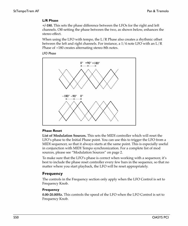
StTempoTrem AF Pan & Tremolo
Eng
lish
L/R Phase+/-180. This sets the phase difference between the LFOs for the right and left channels. Off-setting the phase between the two, as shown below, enhances the stereo effect.
When using the LFO with tempo, the L/R Phase also creates a rhythmic offset between the left and right channels. For instance, a 1/4 note LFO with an L/R Phase of +180 creates alternating stereo 8th notes.
LFO Phase
Phase ResetList of Modulation Sources. This sets the MIDI controller which will reset the LFO’s phase to the Initial Phase point. You can use this to trigger the LFO from a MIDI sequencer, so that it always starts at the same point. This is especially useful in conjunction with MIDI Tempo synchronization. For a complete list of mod sources, please see “Modulation Sources” on page 2.
To make sure that the LFO’s phase is correct when working with a sequencer, it’s best to include the phase reset controller every few bars in the sequence, so that no matter where you start playback, the LFO will be reset appropriately.
FrequencyThe controls in the Frequency section only apply when the LFO Control is set to Frequency Knob.
Frequency0.00-20.00Hz. This controls the speed of the LFO when the LFO Control is set to Frequency Knob.
0° +90° +180°
0°–90°–180°
550 OASYS PCI

Pan & Tremolo StTempoTrem AF
Frequency ModList of Modulation Sources. This sets the modulation source for controlling the LFO speed. For a complete list, please see “Modulation Sources” on page 2.
Mod Amount+/-100. This sets the amount by which the mod source affects the LFO speed.
Tempo
Manual Tempo40-240 bpm. This sets the tempo when the LFO Control is set to Manual Tempo.
Subdivision1/32, 1/32 dotted, 1/16, 1/16 dotted, 1/16 triplet, 1/8, 1/8 dotted, 1/8 triplet, 1/4, 1/4 dotted, 1/4 triplet, 1/2, 1/2 dotted, 1/2 triplet, 1 whole note, 2 whole notes. This sets the note value of a single LFO waveform cycle when the LFO Control is set to either Manual Tempo or MIDI Tempo.
Output
Wet/DryDry, 1:99-99:1, Wet. This sets the balance between the effect and the dry signal.
Wet/Dry ModList of Modulation Sources. This sets the modulation source for controlling the wet/dry mix. For a complete list, please see “Modulation Sources” on page 2.
Mod Amount+/-100. This sets the amount by which the mod source affects the wet/dry mix.
Wet/Dry Auto FadeOn, Off. This enables modulation of the wet/dry mix via the auto fade envelope.
OASYS PCI 551

Tempo Tremolo Pan & Tremolo
Eng
lish
Tempo TremoloThis is a mono-in, mono-out tremolo with a complex, MIDI-syncable tempo LFO. Try modulating the LFO parameters, such as shape and smoothing, in real time.
For detailed instructions on working with MIDI-synced LFOs, see “MIDI Tempo LFOs” on page 5.
Input
SourceLeft, L + R. This is a mono-in, mono-out effect. Stereo signals are preserved in the dry mix at the output, but the effect itself has only a single, mono input.
When this is set to Left, only the left channel will be routed into the effect.
When this is set to L + R, the left and right channels will be summed together, and then routed into the effect.
Level-INF, -69.0 to 0.0dB. This sets the input level for the effect. It does not affect the dry signal.
Tremolo
Depth0-100. This controls the depth of the volume modulation.
Depth ModList of Modulation Sources. This sets the modulation source for controlling the tremolo depth. For a complete list, please see “Modulation Sources” on page 2.
Mod Amount+/-100. This sets the amount by which the mod source affects the tremolo depth.
LFO
Waveform
WaveformTriangle, Sine, Saw Up, Saw Down, Square. This selects the waveform of the LFO. See the graphic below for more information.
552 OASYS PCI

Pan & Tremolo Tempo Tremolo
LFO Waveforms and Phase
0˚ 90˚ 180˚-90˚-180˚ 0˚ 90˚ 180˚-90˚-180˚
+/-180˚ -90˚ 0˚90˚0˚
0˚ 90˚ 180˚-90˚-180˚
+/-180˚ -90˚ 0˚90˚0˚
Triangle Sine
Saw DownSaw Up
Square
OASYS PCI 553

Tempo Tremolo Pan & Tremolo
Eng
lish
Shape+/-100. This adjusts the shape of the LFO waveform, from logarithmic to linear to exponential. Positive values shape the waveform so that it spends more time in the “up” part of the cycle, and negative values make it spend more time in the “down” part of the cycle, as shown below.
LFO Shape
Smoothing0-100. This allows you to filter the LFO waveform, so that it becomes more rounded, less angular. With moderately high amounts of smoothing, the triangle and square waveforms will start to approximate sine waves, and the discontinuous peaks of the saw waveforms will become smooth transitions. With very high amounts of smoothing, the waveform may loose much of its shape, and fall quite short of its maximum and minimum values.
LFO ControlFrequency Knob, Manual Tempo, MIDI Tempo. The LFO speed can be controlled either by the Frequency knob (including the mod source), the Manual Tempo knob, or by MIDI Tempo (derived from MIDI clocks).
If this is set to Frequency Knob, then the LFO speed will be controlled by the settings in the Frequency section, including the mod source and amount.
If this is set to Manual Tempo, then the Manual Tempo knob will set the basic tempo, and the note value set in the Subdivisions menu will control the LFO speed.
If this is set to MIDI Tempo, then incoming MIDI Clocks will set the basic tempo, and the note value set in the Subdivisions menu will control the LFO speed.
Phase
Initial PhaseThis sets the point in the waveform at which the LFO starts. Whenever the Phase Reset controller is received, the LFO will start from the Initial Phase point.
LFO Shape = 0 to +100 LFO Shape = 0 to -100
Sine Waveform
554 OASYS PCI

Pan & Tremolo Tempo Tremolo
Phase ResetList of Modulation Sources. This sets the MIDI controller which will reset the LFO’s phase to the Initial Phase point. You can use this to trigger the LFO from a MIDI sequencer, so that it always starts at the same point. This is especially useful in conjunction with MIDI Tempo synchronization. For a complete list of mod sources, please see “Modulation Sources” on page 2.
To make sure that the LFO’s phase is correct when working with a sequencer, it’s best to include the phase reset controller every few bars in the sequence, so that no matter where you start playback, the LFO will be reset appropriately.
FrequencyThe controls in the Frequency section only apply when the LFO Control is set to Frequency Knob.
Frequency0.00-20.00Hz. This controls the speed of the LFO when the LFO Control is set to Frequency Knob.
Frequency ModList of Modulation Sources. This sets the modulation source for controlling the LFO speed. For a complete list, please see “Modulation Sources” on page 2.
Mod Amount+/-20.00Hz. This sets the amount by which the mod source affects the LFO speed.
Tempo
Manual Tempo40-240 bpm. This sets the tempo when the LFO Control is set to Manual Tempo.
Subdivision1/32, 1/32 dotted, 1/16, 1/16 dotted, 1/16 triplet, 1/8, 1/8 dotted, 1/8 triplet, 1/4, 1/4 dotted, 1/4 triplet, 1/2, 1/2 dotted, 1/2 triplet, 1 whole note, 2 whole notes. This sets the note value of a single LFO waveform cycle when the LFO Control is set to either Manual Tempo or MIDI Tempo.
Output
Wet/DryDry, 1:99-99:1, Wet. This sets the balance between the effect and the dry signal.
Wet/Dry ModList of Modulation Sources. This sets the modulation source for controlling the wet/dry mix. For a complete list, please see “Modulation Sources” on page 2.
OASYS PCI 555

Tempo Tremolo Pan & Tremolo
Eng
lish
Mod Amount+/-100. This sets the amount by which the mod source affects the wet/dry mix.
556 OASYS PCI
Pan & Tremolo Tremolo
TremoloThis is a mono-in, mono-out tremolo effect.
Input
SourceLeft, L + R. This is a mono-in, mono-out effect. Stereo signals are preserved in the dry mix at the output, but the effect itself has only a single, mono input.
When this is set to Left, only the left channel will be routed into the effect.
When this is set to L + R, the left and right channels will be summed together, and then routed into the effect.
Level-INF, -69.0 to 0.0dB. This sets the input level for the effect. It does not affect the dry signal.
Tremolo
Depth0-100. This controls the depth of the volume modulation.
Depth ModList of Modulation Sources. This sets the modulation source for controlling the tremolo depth. For a complete list, please see “Modulation Sources” on page 2.
Mod Amount+/-100. This sets the amount by which the mod source affects the tremolo depth.
LFO
WaveformTriangle, Sine, Down, Up, Square. This selects the waveform for the LFO.
Shape+/-100. This adjusts the shape of the LFO waveform, from logarithmic to linear to exponential. Positive values shape the waveform so that it spends more time in the “up” part of the cycle, and negative values make it spend more time in the “down” part of the cycle, as shown below.
OASYS PCI 557

Tremolo Pan & Tremolo
Eng
lish
LFO Shape
Frequency0.00-20.00Hz. This controls the speed of the LFO.
Frequency ModList of Modulation Sources. This sets the modulation source for controlling the LFO frequency. For a complete list, please see “Modulation Sources” on page 2.
Mod Amount+/-20.00Hz. This sets the amount by which the mod source affects the LFO frequency.
Output
Wet/DryDry, 1:99-99:1, Wet. This sets the balance between the effect and the dry signal.
Wet/Dry ModList of Modulation Sources. This sets the modulation source for controlling the wet/dry mix. For a complete list, please see “Modulation Sources” on page 2.
Mod Amount+/-100. This sets the amount by which the mod source affects the wet/dry mix.
LFO Shape = 0 to +100 LFO Shape = 0 to -100
Sine Waveform
558 OASYS PCI

Phasers

Envelope Phaser Phasers
Eng
lish
Envelope PhaserThis is a mono-in, mono-out phaser based on an envelope instead of an LFO. You can trigger the envelope via MIDI, and also simply control the phaser frequency directly from a MIDI controller.
Input
SourceLeft, L + R. This is a mono-in, mono-out effect. Stereo signals are preserved in the dry mix at the output, but the effect itself has only a single, mono input.
When this is set to Left, only the left channel will be routed into the effect.
When this is set to L + R, the left and right channels will be summed together, and then routed into the effect.
Level-INF, -69.0 to 0.0dB. This sets the input level for the effect. It does not affect the dry signal.
Envelope Phaser
Bottom0-100. This sets the phaser frequency when the envelope or mod source is at minimum.
Top0-100. This sets the phaser frequency when the envelope or mod source is at maximum.
Sweep ModeEG, Mod Source. This determines how the phaser will be controlled.
EG. The phaser will be controlled by the envelope generator (EG).
Mod Source. The phaser will be controlled directly by the MIDI mod source.
EG Trigger/ModList of Modulation Sources. When Sweep Mode is set to EG, this selects the modulation source that triggers the envelope. When Sweep Mode is set to Mod Source, this selects the modulation source that controls the phaser. For a complete list of modulation sources, please see “Modulation Sources” on page 2.
Note EG RetrigOn, Off. This determines the way that the envelope triggers when the Trigger Source is set to Note Gate or Note Gate + Sustain.
560 OASYS PCI

Phasers Envelope Phaser
On. When this is on, the envelope will be triggered whenever a key is pressed.
Off. When this is off, the envelope will only be retriggered after all currently held notes have been released.
EG Attack0-100. This sets the attack time of the envelope–the time that it takes to reach its maximum value after being triggered.
EG Decay0-100. This sets the release time of the envelope–the time that it takes to fall back to its minimum value after the trigger is released.
Resonance+/-100. This sets the amount of resonance in the phaser effect. Higher resonance settings create a more extreme sound.
Damping0-100. This controls the amount of high frequency damping in the phaser resonance.
Output
ModeMono, Stereo. This controls whether the effect output is mono or simulated stereo.
When this is set to Mono, the output is in mono.
When this is set to Stereo, the output is simulated stereo, with the right effect output inverted. Note that this simulated stereo effect is not mono-compatible.
Wet/DryDry, 1:99-99:1, Wet. This sets the balance between the effect and the dry signal.
Wet/Dry ModList of Modulation Sources. This sets the modulation source for controlling the wet/dry mix. For a complete list, please see “Modulation Sources” on page 2.
Mod Amount+/-100. This sets the amount by which the mod source affects the wet/dry mix.
Invert Wet PhaseOn, Off. This allows you to invert the phase of the wet signal.
OASYS PCI 561

Phaser Phasers
Eng
lish
PhaserThis is a mono-in, mono-out phaser effect.
Input
SourceLeft, L + R. This is a mono-in, mono-out effect. Stereo signals are preserved in the dry mix at the output, but the effect itself has only a single, mono input.
When this is set to Left, only the left channel will be routed into the effect.
When this is set to L + R, the left and right channels will be summed together, and then routed into the effect.
Level-INF, -69.0 to 0.0dB. This sets the input level for the effect. It does not affect the dry signal.
Phaser
Center0-100. This sets the center frequency of the phaser.
Depth0-100. This controls the amount of LFO modulation of the center frequency.
Resonance+/-100. This sets the amount of resonance in the phaser effect. Higher resonance settings create a more extreme sound.
Hi Damping0-100. This controls the amount of high frequency damping in the phaser resonance.
LFO
WaveformTriangle, Sine. This selects the waveform for the LFO.
Shape+/-100. This adjusts the shape of the LFO waveform, from logarithmic to linear to exponential. Positive values shape the waveform so that it spends more time in the “up” part of the cycle, and negative values make it spend more time in the “down” part of the cycle, as shown below.
562 OASYS PCI

Phasers Phaser
LFO Shape
Frequency0.00-20.00Hz. This controls the speed of the LFO.
Frequency ModList of Modulation Sources. This sets the modulation source for controlling the LFO frequency. For a complete list, please see “Modulation Sources” on page 2.
Mod Amount+/-20.00Hz. This sets the amount by which the mod source affects the LFO frequency.
Output
ModeMono, Stereo. This controls whether the effect output is mono or simulated stereo.
When this is set to Mono, the output is in mono.
When this is set to Stereo, the output is simulated stereo, with the right effect output inverted. Note that this simulated stereo effect is not mono-compatible.
Wet/DryDry, 1:99-99:1, Wet. This sets the balance between the effect and the dry signal.
Wet/Dry ModList of Modulation Sources. This sets the modulation source for controlling the wet/dry mix. For a complete list, please see “Modulation Sources” on page 2.
Mod Amount+/-100. This sets the amount by which the mod source affects the wet/dry mix.
LFO Shape = 0 to +100 LFO Shape = 0 to -100
Sine Waveform
OASYS PCI 563

St Env Phaser Phasers
Eng
lish
St Env PhaserThis is a stereo-in, stereo-out phaser based on an envelope instead of an LFO. You can trigger the envelope via MIDI, and also simply control the phaser frequency directly from a MIDI controller.
Input
Level-INF, -69.0 to 0.0dB. This sets the input level for the effect. It does not affect the dry signal.
Stereo Envelope Phaser
L Bottom0-100. This sets the left phaser frequency when the envelope or mod source is at minimum.
L Top0-100. This sets the left phaser frequency when the envelope or mod source is at maximum.
R Bottom0-100. This sets the right phaser frequency when the envelope or mod source is at minimum.
R Top0-100. This sets the right phaser frequency when the envelope or mod source is at maximum.
Sweep ModeEG, Mod Source. This determines how the phaser will be controlled.
EG. The phaser will be controlled by the envelope generator (EG).
Mod Source. The phaser will be controlled directly by the MIDI mod source.
EG Trigger/ModList of Modulation Sources. When Sweep Mode is set to EG, this selects the modulation source that triggers the envelope. When Sweep Mode is set to Mod Source, this selects the modulation source that controls the phaser. For a complete list of modulation sources, please see “Modulation Sources” on page 2.
564 OASYS PCI

Phasers St Env Phaser
Note EG RetrigOn, Off. This determines the way that the envelope triggers when the Trigger Source is set to Note Gate or Note Gate + Sustain.
On. When this is on, the envelope will be triggered whenever a key is pressed.
Off. When this is off, the envelope will only be retriggered after all currently held notes have been released.
EG Attack0-100. This sets the attack time of the envelope–the time that it takes to reach its maximum value after being triggered.
EG Decay0-100. This sets the release time of the envelope–the time that it takes to fall back to its minimum value after the trigger is released.
Resonance+/-100. This sets the amount of resonance in the phaser effect. Higher resonance settings create a more extreme sound.
Damping0-100. This controls the amount of high frequency damping in the phaser resonance.
Spread+/-100. This controls the width of the effect’s stereo image, without affecting the dry signal. A value of +100 gives the widest stereo image, and a value of 0 collapses the output to mono. Negative values will reverse the left and right channels of the effect output.
Output
Wet/DryDry, 1:99-99:1, Wet. This sets the balance between the effect and the dry signal.
Wet/Dry ModList of Modulation Sources. This sets the modulation source for controlling the wet/dry mix. For a complete list, please see “Modulation Sources” on page 2.
Mod Amount+/-100. This sets the amount by which the mod source affects the wet/dry mix.
Invert Wet PhaseOn, Off. This allows you to invert the phase of the wet signal.
OASYS PCI 565

St Phaser Phasers
Eng
lish
St PhaserThis is a stereo-in, stereo-out phaser effect.
Input
Level-INF, -69.0 to 0.0dB. This sets the input level for the effect. It does not affect the dry signal.
Stereo Phaser
Center0-100. This sets the center frequency of the phaser.
Depth0-100. This controls the amount of LFO modulation of the center frequency.
Hi Damping0-100. This controls the amount of high frequency damping in the phaser resonance.
Resonance+/-100. This sets the amount of resonance in the phaser effect. Higher resonance settings create a more extreme sound.
Spread+/-100. This controls the width of the effect’s stereo image, without affecting the dry signal. A value of +100 gives the widest stereo image, and a value of 0 collapses the output to mono. Negative values will reverse the left and right channels of the effect output.
LFO
WaveformTriangle, Sine. This selects the waveform for the LFO.
Shape+/-100. This adjusts the shape of the LFO waveform, from logarithmic to linear to exponential. Positive values shape the waveform so that it spends more time in the “up” part of the cycle, and negative values make it spend more time in the “down” part of the cycle, as shown below.
566 OASYS PCI

Phasers St Phaser
LFO Shape
L/R Phase+/-180. This sets the phase difference between the LFOs for the right and left channels. Off-setting the phase between the two, as shown below, enhances the stereo effect.
LFO Phase
Frequency0.00-20.00Hz. This controls the speed of the LFO.
Frequency ModList of Modulation Sources. This sets the modulation source for controlling the LFO frequency. For a complete list, please see “Modulation Sources” on page 2.
LFO Shape = 0 to +100 LFO Shape = 0 to -100
Sine Waveform
0° +90° +180°
0°–90°–180°
OASYS PCI 567

St Phaser Phasers
Eng
lish
Mod Amount+/-20.00Hz. This sets the amount by which the mod source affects the LFO frequency.
Output
Wet/DryDry, 1:99-99:1, Wet. This sets the balance between the effect and the dry signal.
Wet/Dry ModList of Modulation Sources. This sets the modulation source for controlling the wet/dry mix. For a complete list, please see “Modulation Sources” on page 2.
Mod Amount+/-100. This sets the amount by which the mod source affects the wet/dry mix.
Invert Wet PhaseOn, Off. This allows you to invert the phase of the wet signal.
568 OASYS PCI
Phasers St RandomPhaser
St RandomPhaserThis is a stereo-in, stereo-out phaser, with step-shaped and sample-and-hold waveforms.
Input
Level-INF, -69.0 to 0.0dB. This sets the input level for the effect. It does not affect the dry signal.
Stereo Phaser
Center0-100. This sets the center frequency of the phaser.
Depth0-100. This controls the amount of LFO modulation of the center frequency.
Depth ModList of Modulation Sources. This sets the modulation source for controlling the LFO depth. For a complete list, please see “Modulation Sources” on page 2.
Mod Amount+/-100. This sets the amount by which the mod source affects the LFO depth.
Resonance+/-100. This sets the amount of resonance in the phaser effect. Higher resonance settings create a more extreme sound.
Hi Damping0-100. This controls the amount of high frequency damping in the phaser resonance.
Spread+/-100. This controls the width of the effect’s stereo image, without affecting the dry signal. A value of +100 gives the widest stereo image, and a value of 0 collapses the output to mono. Negative values will reverse the left and right channels of the effect output.
LFO
WaveformStep Triangle, Step Sine, Random. This selects the main waveform for the LFO.
OASYS PCI 569

St RandomPhaser Phasers
Eng
lish
L/R Phase+/-180. This sets the phase difference between the LFOs for the right and left channels. Off-setting the phase between the two, as shown below, enhances the stereo effect.
LFO Phase
Frequency0.00-20.00Hz. This sets the frequency for the main LFO.
Step Freq0.00-50.00Hz. This sets the frequency of the LFO steps. If the Random waveform is being used, then this will determine the frequency of the sample-and-hold effect.
Frequency ModList of Modulation Sources. This sets the modulation source for controlling the LFO frequencies. The same modulator can be used for both the main LFO and the step LFO. For a complete list, please see “Modulation Sources” on page 2.
Freq Mod Amount+/-20.00Hz. This sets the amount by which the mod source affects the frequency of the main LFO .
Step Mod Amount+/-50.00Hz. This sets the amount by which the mod source affects the frequency of the step LFO.
0° +90° +180°
0°–90°–180°
570 OASYS PCI

Phasers St RandomPhaser
Random Step LFO
Output
Wet/DryDry, 1:99-99:1, Wet. This sets the balance between the effect and the dry signal.
Wet/Dry ModList of Modulation Sources. This sets the modulation source for controlling the wet/dry mix. For a complete list, please see “Modulation Sources” on page 2.
Mod Amount+/-100. This sets the amount by which the mod source affects the wet/dry mix.
Invert Wet PhaseOn, Off. This allows you to invert the phase of the wet signal.
LFO Step Freq
LFO Frequency
LFO Step Freq
Step-Tri Random
OASYS PCI 571

St TempoPhase2 Phasers
Eng
lish
St TempoPhase2This is a stereo-in, stereo-out phaser, with a complex MIDI-synced main LFO. The main LFO can itself be modulated by a second MIDI-synced step LFO.
For detailed instructions on working with MIDI-synced LFOs, see “MIDI Tempo LFOs” on page 5.
Input
Level-INF, -69.0 to 0.0dB. This sets the input level for the effect. It does not affect the dry signal.
Stereo Step / Random Phaser
Center0-100. This sets the center frequency of the phaser.
Depth0-100. This controls the amount of LFO modulation of the center frequency.
Depth ModList of Modulation Sources. This sets the modulation source for controlling the LFO depth. For a complete list, please see “Modulation Sources” on page 2.
Mod Amount+/-100. This sets the amount by which the mod source affects the LFO depth.
Resonance+/-100. This sets the amount of resonance in the phaser effect. Higher resonance settings create a more extreme sound.
Hi Damping0-100. This controls the amount of high frequency damping in the phaser resonance.
Spread+/-100. This controls the width of the effect’s stereo image, without affecting the dry signal. A value of +100 gives the widest stereo image, and a value of 0 collapses the output to mono. Negative values will reverse the left and right channels of the effect output.
572 OASYS PCI

Phasers St TempoPhase2
LFO
Waveform
WaveformTriangle, Sine, Saw Up, Saw Down, Square, Noise. This selects the waveform of the main LFO.
Shape+/-100. This adjusts the shape of the LFO waveform, from logarithmic to linear to exponential. Positive values shape the waveform so that it spends more time in the “up” part of the cycle, and negative values make it spend more time in the “down” part of the cycle, as shown below.
LFO Shape
Smoothing0-100. This allows you to filter the LFO waveform, so that it becomes more rounded, less angular. With moderately high amounts of smoothing, the triangle and square waveforms will start to approximate sine waves, and the discontinuous peaks of the saw waveforms will become smooth transitions. With very high amounts of smoothing, the waveform may loose much of its shape, and fall quite short of its maximum and minimum values.
StepOn, Off. This turns the step LFO on and off.
LFO Shape = 0 to +100 LFO Shape = 0 to -100
Sine Waveform
OASYS PCI 573

St TempoPhase2 Phasers
Eng
lish
LFO Waveforms and Phase
LFO ControlFrequency Knob, Manual Tempo, MIDI Tempo. The LFO speed can be controlled either by the Frequency knob (including the mod source), the Manual Tempo knob, or by MIDI Tempo (derived from MIDI clocks).
0˚ 90˚ 180˚-90˚-180˚ 0˚ 90˚ 180˚-90˚-180˚
+/-180˚ -90˚ 0˚90˚0˚
0˚ 90˚ 180˚-90˚-180˚ 0˚ 90˚ 180˚-90˚-180˚
+/-180˚ -90˚ 0˚90˚0˚
Triangle Sine
Saw DownSaw Up
NoiseSquare
574 OASYS PCI

Phasers St TempoPhase2
If this is set to Frequency Knob, then the LFO speed will be controlled by the settings in the Frequency section, including the mod source and amount.
If this is set to Manual Tempo, then the Manual Tempo knob will set the basic tempo, and the note value set in the Subdivisions menu will control the LFO speed.
If this is set to MIDI Tempo, then incoming MIDI Clocks will set the basic tempo, and the note value set in the Subdivisions menu will control the LFO speed.
Phase
Initial Phase+/-180. This sets the point in the waveform at which the LFO starts. Whenever the Phase Reset controller is received, the LFO will start from the Initial Phase point.
L/R Phase+/-180. This sets the phase difference between the LFOs for the right and left channels. Off-setting the phase between the two, as shown below, enhances the stereo effect–although with panning in particular, the two channels must contain fairly discrete material for this effect to be noticeable.
When using the LFO with tempo, the L/R Phase also creates a rhythmic offset between the left and right channels. For instance, a 1/4 note LFO with an L/R Phase of +180 creates alternating stereo 8th notes.
LFO Phase
Phase ResetList of Modulation Sources. This sets the MIDI controller which will reset the LFO’s phase to the Initial Phase point. You can use this to trigger the LFO from a MIDI sequencer, so that it always starts at the same point. This is especially useful
0° +90° +180°
0°–90°–180°
OASYS PCI 575

St TempoPhase2 Phasers
Eng
lish
in conjunction with MIDI Tempo synchronization. For a complete list of mod sources, please see “Modulation Sources” on page 2.
To make sure that the LFO’s phase is correct when working with a sequencer, it’s best to include the phase reset controller every few bars in the sequence, so that no matter where you start playback, the LFO will be reset appropriately.
FrequencyThe controls in the Frequency section only apply when the LFO Control is set to Frequency Knob.
Frequency0.00-20.00Hz. This controls the speed of the LFO when the LFO Control is set to Frequency Knob.
Frequency ModList of Modulation Sources. This sets the modulation source for controlling the LFO speed. For a complete list, please see “Modulation Sources” on page 2.
Mod Amount+/-20.00Hz. This sets the amount by which the mod source affects the LFO speed.
Tempo
Manual Tempo40-240 bpm. This sets the tempo when the LFO Control is set to Manual Tempo.
Subdivision1/32, 1/32 dotted, 1/16, 1/16 dotted, 1/16 triplet, 1/8, 1/8 dotted, 1/8 triplet, 1/4, 1/4 dotted, 1/4 triplet, 1/2, 1/2 dotted, 1/2 triplet, 1 whole note, 2 whole notes. This sets the note value of a single LFO waveform cycle when the LFO Control is set to either Manual Tempo or MIDI Tempo.
Step FrequencyStep LFO
LFO Step Freq
LFO Frequency
LFO Step Freq
Step-Tri Random
576 OASYS PCI

Phasers St TempoPhase2
Step Freq0.00-80.00Hz. This controls the speed of the step LFO when the LFO Control is set to Frequency Knob.
Step Freq ModList of Modulation Sources. This sets the modulation source for controlling the speed of the step LFO. For a complete list, please see “Modulation Sources” on page 2.
Step Mod+/-80.00Hz. This sets the amount by which the mod source affects the speed of the step LFO.
Step ControlFrequency Knob, Manual Tempo, MIDI Tempo. The speed of the step LFO can be controlled either by the Frequency knob (including the mod source), the Manual Tempo knob, or by MIDI Tempo (derived from MIDI clocks).
If this is set to Frequency Knob, then the step LFO speed will be controlled by the settings in the Frequency section, including the mod source and amount.
If this is set to Manual Tempo, then the Manual Tempo knob will set the basic tempo, and the note value set in the Subdivisions menu will control the step LFO speed.
If this is set to MIDI Tempo, then incoming MIDI Clocks will set the basic tempo, and the note value set in the Subdivisions menu will control the step LFO speed.
Step Tempo
Manual Tempo40-240 bpm. This sets the tempo when the Step Control is set to Manual Tempo.
Subdivision1/32, 1/32 dotted, 1/16, 1/16 dotted, 1/16 triplet, 1/8, 1/8 dotted, 1/8 triplet, 1/4, 1/4 dotted, 1/4 triplet, 1/2, 1/2 dotted, 1/2 triplet, 1 whole note, 2 whole notes. This sets the note value of a single LFO waveform cycle when the Step Control is set to either Manual Tempo or MIDI Tempo.
Output
Wet/DryDry, 1:99-99:1, Wet. This sets the balance between the effect and the dry signal.
Wet/Dry ModList of Modulation Sources. This sets the modulation source for controlling the wet/dry mix. For a complete list, please see “Modulation Sources” on page 2.
OASYS PCI 577

St TempoPhase2 Phasers
Eng
lish
Mod Amount+/-100. This sets the amount by which the mod source affects the wet/dry mix.
Invert Wet PhaseOn, Off. This allows you to invert the phase of the wet signal.
578 OASYS PCI

Phasers St TempoPhaser
St TempoPhaserThis is a stereo-in, stereo-out phaser with a complex, MIDI-syncable tempo LFO. Try modulating the LFO parameters, such as shape, smoothing, and L/R phase, in real time.
For detailed instructions on working with MIDI-synced LFOs, see “MIDI Tempo LFOs” on page 5.
Input
Level-INF, -69.0 to 0.0dB. This sets the input level for the effect. It does not affect the dry signal.
Stereo Phaser
Center0-100. This sets the center frequency of the phaser.
Depth0-100. This controls the amount of LFO modulation of the center frequency.
Resonance+/-100. This sets the amount of resonance in the phaser effect. Higher resonance settings create a more extreme sound.
Hi Damping0-100. This controls the amount of high frequency damping in the phaser resonance.
Spread+/-100. This controls the width of the effect’s stereo image, without affecting the dry signal. A value of +100 gives the widest stereo image, and a value of 0 collapses the output to mono. Negative values will reverse the left and right channels of the effect output.
LFO
Waveform
WaveformTriangle, Sine, Saw Up, Saw Down, Square, Sample & Hold. This selects the waveform of the LFO.
OASYS PCI 579

St TempoPhaser Phasers
Eng
lish
LFO Waveforms and Phase
Shape+/-100. This adjusts the shape of the LFO waveform, from logarithmic to linear to exponential. Positive values shape the waveform so that it spends more time in the “up” part of the cycle, and negative values make it spend more time in the “down” part of the cycle, as shown below.
0˚ 90˚ 180˚-90˚-180˚ 0˚ 90˚ 180˚-90˚-180˚
+/-180˚ -90˚ 0˚90˚0˚
0˚ 90˚ 180˚-90˚-180˚ 0˚ 90˚ 180˚-90˚-180˚
+/-180˚ -90˚ 0˚90˚0˚
Triangle Sine
Saw DownSaw Up
Sample & HoldSquare
580 OASYS PCI

Phasers St TempoPhaser
LFO Shape
Smoothing0-100. This allows you to filter the LFO waveform, so that it becomes more rounded, less angular. With moderately high amounts of smoothing, the triangle and square waveforms will start to approximate sine waves, and the discontinuous peaks of the saw waveforms will become smooth transitions. With very high amounts of smoothing, the waveform may loose much of its shape, and fall quite short of its maximum and minimum values.
LFO ControlFrequency Knob, Manual Tempo, MIDI Tempo. The LFO speed can be controlled either by the Frequency knob (including the mod source), the Manual Tempo knob, or by MIDI Tempo (derived from MIDI clocks).
If this is set to Frequency Knob, then the LFO speed will be controlled by the settings in the Frequency section, including the mod source and amount.
If this is set to Manual Tempo, then the Manual Tempo knob will set the basic tempo, and the note value set in the Subdivisions menu will control the LFO speed.
If this is set to MIDI Tempo, then incoming MIDI Clocks will set the basic tempo, and the note value set in the Subdivisions menu will control the LFO speed.
Phase
Initial Phase+/-180. This sets the point in the waveform at which the LFO starts. Whenever the Phase Reset controller is received, the LFO will start from the Initial Phase point.
L/R Phase+/-180. This sets the phase difference between the LFOs for the right and left channels. Off-setting the phase between the two, as shown below, enhances the stereo effect–although with panning in particular, the two channels must contain fairly discrete material for this effect to be noticeable.
LFO Shape = 0 to +100 LFO Shape = 0 to -100
Sine Waveform
OASYS PCI 581

St TempoPhaser Phasers
Eng
lish
When using the LFO with tempo, the L/R Phase also creates a rhythmic offset between the left and right channels. For instance, a 1/4 note LFO with an L/R Phase of +180 creates alternating stereo 8th notes.
LFO Phase
Phase ResetList of Modulation Sources. This sets the MIDI controller which will reset the LFO’s phase to the Initial Phase point. You can use this to trigger the LFO from a MIDI sequencer, so that it always starts at the same point. This is especially useful in conjunction with MIDI Tempo synchronization. For a complete list of mod sources, please see “Modulation Sources” on page 2.
To make sure that the LFO’s phase is correct when working with a sequencer, it’s best to include the phase reset controller every few bars in the sequence, so that no matter where you start playback, the LFO will be reset appropriately.
FrequencyThe controls in the Frequency section only apply when the LFO Control is set to Frequency Knob.
Frequency0.00-20.00Hz. This controls the speed of the LFO when the LFO Control is set to Frequency Knob.
Frequency ModList of Modulation Sources. This sets the modulation source for controlling the LFO speed. For a complete list, please see “Modulation Sources” on page 2.
Mod Amount+/-20.00Hz. This sets the amount by which the mod source affects the LFO speed.
0° +90° +180°
0°–90°–180°
582 OASYS PCI

Phasers St TempoPhaser
Tempo
Manual Tempo40-240 bpm. This sets the tempo when the LFO Control is set to Manual Tempo.
Subdivision1/32, 1/32 dotted, 1/16, 1/16 dotted, 1/16 triplet, 1/8, 1/8 dotted, 1/8 triplet, 1/4, 1/4 dotted, 1/4 triplet, 1/2, 1/2 dotted, 1/2 triplet, 1 whole note, 2 whole notes. This sets the note value of a single LFO waveform cycle when the LFO Control is set to either Manual Tempo or MIDI Tempo.
Output
Wet/DryDry, 1:99-99:1, Wet. This sets the balance between the effect and the dry signal.
Wet/Dry ModList of Modulation Sources. This sets the modulation source for controlling the wet/dry mix. For a complete list, please see “Modulation Sources” on page 2.
Mod Amount+/-100. This sets the amount by which the mod source affects the wet/dry mix.
Invert Wet PhaseOn, Off. This allows you to invert the phase of the wet signal.
OASYS PCI 583

Tempo Phaser Phasers
Eng
lish
Tempo PhaserThis is a mono-in, mono-out phaser with a complex, MIDI-syncable tempo LFO. Try modulating the LFO parameters, such as shape and smoothing, in real time.
For detailed instructions on working with MIDI-synced LFOs, see “MIDI Tempo LFOs” on page 5.
Input
SourceLeft, L + R. This is a mono-in, mono-out effect. Stereo signals are preserved in the dry mix at the output, but the effect itself has only a single, mono input.
When this is set to Left, only the left channel will be routed into the effect.
When this is set to L + R, the left and right channels will be summed together, and then routed into the effect.
Level-INF, -69.0 to 0.0dB. This sets the input level for the effect. It does not affect the dry signal.
Phaser
Center0-100. This sets the center frequency of the phaser.
Depth0-100. This controls the amount of LFO modulation of the center frequency.
Resonance+/-100. This sets the amount of resonance in the phaser effect. Higher resonance settings create a more extreme sound.
Damping0-100. This controls the amount of high frequency damping in the phaser resonance.
LFO
Waveform
WaveformTriangle, Sine, Saw Up, Saw Down, Square, Sample & Hold. This selects the waveform of the LFO.
584 OASYS PCI

Phasers Tempo Phaser
LFO Waveforms and Phase
Shape+/-100. This adjusts the shape of the LFO waveform, from logarithmic to linear to exponential. Positive values shape the waveform so that it spends more time in the “up” part of the cycle, and negative values make it spend more time in the “down” part of the cycle, as shown below.
0˚ 90˚ 180˚-90˚-180˚ 0˚ 90˚ 180˚-90˚-180˚
+/-180˚ -90˚ 0˚90˚0˚
0˚ 90˚ 180˚-90˚-180˚ 0˚ 90˚ 180˚-90˚-180˚
+/-180˚ -90˚ 0˚90˚0˚
Triangle Sine
Saw DownSaw Up
Sample & HoldSquare
OASYS PCI 585

Tempo Phaser Phasers
Eng
lish
LFO Shape
Smoothing0-100. This allows you to filter the LFO waveform, so that it becomes more rounded, less angular. With moderately high amounts of smoothing, the triangle and square waveforms will start to approximate sine waves, and the discontinuous peaks of the saw waveforms will become smooth transitions. With very high amounts of smoothing, the waveform may loose much of its shape, and fall quite short of its maximum and minimum values.
LFO ControlFrequency Knob, Manual Tempo, MIDI Tempo. The LFO speed can be controlled either by the Frequency knob (including the mod source), the Manual Tempo knob, or by MIDI Tempo (derived from MIDI clocks).
If this is set to Frequency Knob, then the LFO speed will be controlled by the settings in the Frequency section, including the mod source and amount.
If this is set to Manual Tempo, then the Manual Tempo knob will set the basic tempo, and the note value set in the Subdivisions menu will control the LFO speed.
If this is set to MIDI Tempo, then incoming MIDI Clocks will set the basic tempo, and the note value set in the Subdivisions menu will control the LFO speed.
Phase
Initial PhaseThis sets the point in the waveform at which the LFO starts. Whenever the Phase Reset controller is received, the LFO will start from the Initial Phase point.
Phase ResetList of Modulation Sources. This sets the MIDI controller which will reset the LFO’s phase to the Initial Phase point. You can use this to trigger the LFO from a MIDI sequencer, so that it always starts at the same point. This is especially useful in conjunction with MIDI Tempo synchronization. For a complete list of mod sources, please see “Modulation Sources” on page 2.
LFO Shape = 0 to +100 LFO Shape = 0 to -100
Sine Waveform
586 OASYS PCI

Phasers Tempo Phaser
To make sure that the LFO’s phase is correct when working with a sequencer, it’s best to include the phase reset controller every few bars in the sequence, so that no matter where you start playback, the LFO will be reset appropriately.
FrequencyThe controls in the Frequency section only apply when the LFO Control is set to Frequency Knob.
Frequency0.00-20.00Hz. This controls the speed of the LFO when the LFO Control is set to Frequency Knob.
Frequency ModList of Modulation Sources. This sets the modulation source for controlling the LFO speed. For a complete list, please see “Modulation Sources” on page 2.
Mod Amount+/-20.00Hz. This sets the amount by which the mod source affects the LFO speed.
Tempo
Manual Tempo40-240 bpm. This sets the tempo when the LFO Control is set to Manual Tempo.
Subdivision1/32, 1/32 dotted, 1/16, 1/16 dotted, 1/16 triplet, 1/8, 1/8 dotted, 1/8 triplet, 1/4, 1/4 dotted, 1/4 triplet, 1/2, 1/2 dotted, 1/2 triplet, 1 whole note, 2 whole notes. This sets the note value of a single LFO waveform cycle when the LFO Control is set to either Manual Tempo or MIDI Tempo.
Output
ModeMono, Stereo. This controls whether the effect output is mono or simulated stereo.
When this is set to Mono, the output is in mono.
When this is set to Stereo, the output is simulated stereo, with the right effect output inverted. Note that this simulated stereo effect is not mono-compatible.
Wet/DryDry, 1:99-99:1, Wet. This sets the balance between the effect and the dry signal.
Wet/Dry ModList of Modulation Sources. This sets the modulation source for controlling the wet/dry mix. For a complete list, please see “Modulation Sources” on page 2.
OASYS PCI 587

Tempo Phaser Phasers
Eng
lish
Mod Amount+/-100. This sets the amount by which the mod source affects the wet/dry mix.
588 OASYS PCI

Phasers Tremolo Phaser
Tremolo PhaserThis stereo-in, stereo-out effect follows a stereo phaser with a stereo tremolo. The phaser and tremolo LFOs are synchronized, with adjustable phase offsets. This effect works particularly well with electric piano sounds.
Input
Level-INF, -69.0 to 0.0dB. This sets the input level for the effect. It does not affect the dry signal.
LFO
Frequency0.00-20.00Hz. This controls the speed of the LFO.
Frequency ModList of Modulation Sources. This sets the modulation source for controlling the LFO frequency. For a complete list, please see “Modulation Sources” on page 2.
Mod Amount+/-100. This sets the amount by which the mod source affects the LFO frequency.
Stereo Phaser
L/R Phase+/-180. This sets the phase difference between the LFOs for the right and left channels, for the phaser only. Off-setting the phase between the two, as shown below, enhances the stereo effect.
OASYS PCI 589

Tremolo Phaser Phasers
Eng
lish
LFO Phase
Center0-100. This sets the center frequency of the phaser.
Depth0-100. This controls the amount of LFO modulation of the center frequency.
Depth ModList of Modulation Sources. This sets the source for controlling the frequency modulation depth. For a complete list, please see “Modulation Sources” on page 2.
Mod Amount+/-100. This sets the amount by which the mod source affects the depth of frequency modulation.
Resonance+/-100. This sets the amount of resonance in the phaser effect. Higher resonance settings create a more extreme sound.
Wet/DryDry, 1:99-99:1, Wet. This sets the balance between the effect and the dry signal, for the phaser only.
Invert Wet PhaseOn, Off. This allows you to invert the phase of the wet signal.
0° +90° +180°
0°–90°–180°
590 OASYS PCI
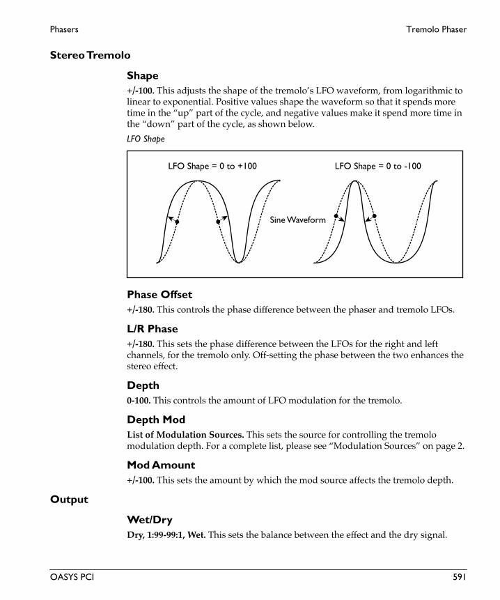
Phasers Tremolo Phaser
Stereo Tremolo
Shape+/-100. This adjusts the shape of the tremolo’s LFO waveform, from logarithmic to linear to exponential. Positive values shape the waveform so that it spends more time in the “up” part of the cycle, and negative values make it spend more time in the “down” part of the cycle, as shown below.
LFO Shape
Phase Offset+/-180. This controls the phase difference between the phaser and tremolo LFOs.
L/R Phase+/-180. This sets the phase difference between the LFOs for the right and left channels, for the tremolo only. Off-setting the phase between the two enhances the stereo effect.
Depth0-100. This controls the amount of LFO modulation for the tremolo.
Depth ModList of Modulation Sources. This sets the source for controlling the tremolo modulation depth. For a complete list, please see “Modulation Sources” on page 2.
Mod Amount+/-100. This sets the amount by which the mod source affects the tremolo depth.
Output
Wet/DryDry, 1:99-99:1, Wet. This sets the balance between the effect and the dry signal.
LFO Shape = 0 to +100 LFO Shape = 0 to -100
Sine Waveform
OASYS PCI 591

Tremolo Phaser Phasers
Eng
lish
Wet/Dry ModList of Modulation Sources. This sets the modulation source for controlling the wet/dry mix. For a complete list, please see “Modulation Sources” on page 2.
Mod Amount+/-100. This sets the amount by which the mod source affects the wet/dry mix.
592 OASYS PCI

Pitch Shifters

2Band PitchShift Pitch Shifters
Eng
lish
2Band PitchShiftThis effect uses a crossover on the input, and then sends the resulting two bands through two independent pitch shifters.
Input
SourceLeft, L + R. This is a mono-in, stereo-out effect. Stereo signals are preserved in the dry mix at the output, but the effect itself has only a single, mono input.
When this is set to Left, only the left channel will be routed into the effect.
When this is set to L + R, the left and right channels will be summed together, and then routed into the effect.
Level-INF, -69.0 to 0.0dB. This sets the input level for the effect. It does not affect the dry signal.
Two Band Pitch Shifter Control
TypeFast, Medium, Slow. This sets the response time and quality of the pitch shifters. The slower the response, the higher the quality.
Lo/Hi Split24-20000Hz. This sets the crossover frequency between the high and low pitch shifters.
Lo/Hi Bal0-100. This sets the level balance between the high and low pitch shifters.
Spread+/-100. This controls the width of the effect’s stereo image, without affecting the dry signal. A value of +100 gives the widest stereo image, and a value of 0 collapses the output to mono. Negative values will reverse the left and right channels of the effect output.
Low
Pitch Shift+/-24. This sets the amount of pitch shift for the low band, in semitones.
594 OASYS PCI

Pitch Shifters 2Band PitchShift
Fine+/-100. .This controls the fine tuning for the low band, in cents (1/100 of a semitone).
Pitch Shift ModList of Modulation Sources. This sets the modulation source for controlling the amount of pitch shift in the low band. For a complete list, please see “Modulation Sources” on page 2.
Mod Amount+/-24. This sets the amount by which the mod source affects the pitch shift, in semitones.
Fine Amount+/-100.0. This sets the amount by which the mod source affects the pitch shift, in cents (1/100 of a semitone).
Damping0-100. This controls the amount of high frequency damping in the low band.
High
Pitch Shift+/-24. This sets the amount of pitch shift for the high band, in semitones.
Fine+/-100. .This controls the fine tuning for the high band, in cents (1/100 of a semitone).
Pitch Shift ModList of Modulation Sources. This sets the modulation source for controlling the amount of pitch shift in the high band. For a complete list, please see “Modulation Sources” on page 2.
Mod Amount+/-24. This sets the amount by which the mod source affects the pitch shift, in semitones.
Fine Amount+/-100.0. This sets the amount by which the mod source affects the pitch shift, in cents (1/100 of a semitone).
Damping0-100. This controls the amount of high frequency damping in the high band.
OASYS PCI 595

2Band PitchShift Pitch Shifters
Eng
lish
Output
Wet/DryDry, 1:99-99:1, Wet. This sets the balance between the effect and the dry signal.
Wet/Dry ModList of Modulation Sources. This sets the modulation source for controlling the wet/dry mix. For a complete list, please see “Modulation Sources” on page 2.
Mod Amount+/-100. This sets the amount by which the mod source affects the wet/dry mix.
596 OASYS PCI

Pitch Shifters Detune
DetuneThis is a subtle pitch shift effect, to be used for thickening, like a chorus.
Input
SourceLeft, L + R. This is a mono-in, mono-out effect. Stereo signals are preserved in the dry mix at the output, but the effect itself has only a single, mono input.
When this is set to Left, only the left channel will be routed into the effect.
When this is set to L + R, the left and right channels will be summed together, and then routed into the effect.
Level-INF, -69.0 to 0.0dB. This sets the input level for the effect. It does not affect the dry signal.
Delay
Delay Time0.0-280.0ms. This sets the amount of delay for the detune effect.
High Damp0-100. This controls the amount of high frequency damping.
Detune
Pitch Shift+/-100.0. .This controls the amount of pitch shift, in cents (1/100 of a semitone).
Pitch Shift ModList of Modulation Sources. This sets the modulation source for controlling the amount of pitch shift. For a complete list, please see “Modulation Sources” on page 2.
Mod Amount+/-100.0. This sets the amount by which the mod source affects the pitch shift, in cents (1/100 of a semitone).
Output
ModeMono, Stereo. This controls whether the effect output is mono or simulated stereo.
OASYS PCI 597

Detune Pitch Shifters
Eng
lish
When this is set to Mono, the output is in mono.
When this is set to Stereo, the output is simulated stereo, with the right effect output inverted. Note that this simulated stereo effect is not mono-compatible.
Wet/DryDry, 1:99-99:1, Wet. This sets the balance between the effect and the dry signal.
Wet/Dry ModList of Modulation Sources. This sets the modulation source for controlling the wet/dry mix. For a complete list, please see “Modulation Sources” on page 2.
Mod Amount+/-100. This sets the amount by which the mod source affects the wet/dry mix.
598 OASYS PCI

Pitch Shifters Pitch Shift Mod
Pitch Shift ModThis effect modulates a subtle detune effect with an LFO.
Input
SourceLeft, L + R. This is a mono-in, stereo-out effect. Stereo signals are preserved in the dry mix at the output, but the effect itself has only a single, mono input.
When this is set to Left, only the left channel will be routed into the effect.
When this is set to L + R, the left and right channels will be summed together, and then routed into the effect.
Level-INF, -69.0 to 0.0dB. This sets the input level for the effect. It does not affect the dry signal.
Pitch Shift Mod
Pitch Shift+/-100.0. .This controls the amount of pitch shift, in cents (1/100 of a semitone).
Depth+/-100.0. This sets the depth of LFO pitch modulation, in cents (1/100 of a semitone).
Depth ModList of Modulation Sources. This sets the modulation source for controlling the LFO depth. For a complete list, please see “Modulation Sources” on page 2.
Mod Amount+/-100.0. This sets the amount by which the mod source affects the pitch shift, in cents (1/100 of a semitone).
Spread0-100. This controls the width of the effect’s stereo image, without affecting the dry signal. A value of +100 gives the widest stereo image, and a value of 0 collapses the output to mono. Negative values will reverse the left and right channels of the effect output.
OASYS PCI 599

Pitch Shift Mod Pitch Shifters
Eng
lish
LFO
WaveformTriangle, Square. This selects the waveform for the LFO.
Frequency0.00-20.00Hz. This controls the speed of the LFO.
Frequency ModList of Modulation Sources. This sets the modulation source for controlling the LFO frequency. For a complete list, please see “Modulation Sources” on page 2.
Mod Amount+/-20.00Hz. This sets the amount by which the mod source affects the LFO frequency.
Output
Wet/DryDry, 1:99-99:1, Wet. This sets the balance between the effect and the dry signal.
Wet/Dry ModList of Modulation Sources. This sets the modulation source for controlling the wet/dry mix. For a complete list, please see “Modulation Sources” on page 2.
Mod Amount+/-100. This sets the amount by which the mod source affects the wet/dry mix.
600 OASYS PCI

Pitch Shifters Pitch Shifter
Pitch ShifterThis effect is a mono-in, mono-out pitch shifter with feedback.
Input
SourceLeft, L + R. This is a mono-in, mono-out effect. Stereo signals are preserved in the dry mix at the output, but the effect itself has only a single, mono input.
When this is set to Left, only the left channel will be routed into the effect.
When this is set to L + R, the left and right channels will be summed together, and then routed into the effect.
Level-INF, -69.0 to 0.0dB. This sets the input level for the effect. It does not affect the dry signal.
Delay
Delay Time0.0-280.0ms. This sets the amount of delay for the pitch shifter.
Feedback+/-100.0. This sets the amount of feedback into the pitch shifter.
High Damp0-100. This controls the amount of high frequency damping.
Pitch Shifter
TypeFast, Medium, Slow. This sets the response time and quality of the pitch shifter. The slower the response, the higher the quality.
Pitch Shift+/-24. This sets the amount of pitch shift, in semitones.
Fine+/-100. .This controls the fine tuning for the pitch shifter, in cents (1/100 of a semitone).
OASYS PCI 601

Pitch Shifter Pitch Shifters
Eng
lish
Pitch Shift ModList of Modulation Sources. This sets the modulation source for controlling the amount of pitch shift. For a complete list, please see “Modulation Sources” on page 2.
Mod Amount+/-24. This sets the amount by which the mod source affects the pitch shift, in semitones.
Fine Amount+/-100.0. This sets the amount by which the mod source affects the pitch shift, in cents (1/100 of a semitone).
Output
ModeMono, Stereo. This controls whether the effect output is mono or simulated stereo.
When this is set to Mono, the output is in mono.
When this is set to Stereo, the output is simulated stereo, with the right effect output inverted. Note that this simulated stereo effect is not mono-compatible.
Wet/DryDry, 1:99-99:1, Wet. This sets the balance between the effect and the dry signal.
Wet/Dry ModList of Modulation Sources. This sets the modulation source for controlling the wet/dry mix. For a complete list, please see “Modulation Sources” on page 2.
Mod Amount+/-100. This sets the amount by which the mod source affects the wet/dry mix.
602 OASYS PCI

Pitch Shifters St Pitch Shifter
St Pitch ShifterThis is a stereo-in, stereo-out pitch shifter, with individual controls for the left and right channels.
Input
Level-INF, -69.0 to 0.0dB. This sets the input level for the effect. It does not affect the dry signal.
Level ModList of Modulation Sources. This sets the modulation source for controlling the input level. For a complete list, please see “Modulation Sources” on page 2.
Mod Amount+/-100. This sets the amount by which the mod source affects the input level.
Delay
Left Delay0.0-170.0ms. This sets the amount of delay for the left channel.
Right Delay0.0-170.0ms. This sets the amount of delay for the right channel.
Feedback+/-100.0. This controls the amount of feedback into the pitch shifters.
High Damp0-100. This adjusts the amount of high frequency damping.
Pitch Shifter (Left and Right)The left and right channels have identical parameters.
Type (Left and Right)Fast, Medium, Slow. This sets the response time and quality of the pitch shifter. The slower the response, the higher the quality.
Pitch Shift (Left and Right)+/-24. This sets the amount of pitch shift, in semitones.
OASYS PCI 603

St Pitch Shifter Pitch Shifters
Eng
lish
Fine (Left and Right)+/-100.0. .This controls the fine tuning for the pitch shifter, in cents (1/100 of a semitone).
Pitch Shift Mod (Left and Right)List of Modulation Sources. This sets the modulation source for controlling the amount of pitch shift. For a complete list, please see “Modulation Sources” on page 2.
Mod Amount (Left and Right)+/-24.0. This sets the amount by which the mod source affects the pitch shift, in semitones.
Fine Amount (Left and Right)+/-100.0. This sets the amount by which the mod source affects the pitch shift, in cents (1/100 of a semitone).
Spread
Spread+/-100.0. This controls the width of the effect’s stereo image, without affecting the dry signal. A value of +100 gives the widest stereo image, and a value of 0 collapses the output to mono. Negative values will reverse the left and right channels of the effect output.
Output
Wet/DryDry, 1:99-99:1, Wet. This sets the balance between the effect and the dry signal.
Wet/Dry ModList of Modulation Sources. This sets the modulation source for controlling the wet/dry mix. For a complete list, please see “Modulation Sources” on page 2.
Mod Amount+/-100. This sets the amount by which the mod source affects the wet/dry mix.
604 OASYS PCI

Reverbs

Hall Ambience Reverbs
Eng
lish
Hall AmbienceThis effect provides the reverberant wash of the “Hall Reverb” effect, without the early reflections or pre-delay, and with only low shelving EQ. It uses relatively little DSP processing power.
Input
SourceLeft, L + R. This is a mono-in, stereo-out effect. Stereo signals are preserved in the dry mix at the output, but the effect itself has only a single, mono input.
When this is set to Left, only the left channel will be routed into the effect.
When this is set to L + R, the left and right channels will be summed together, and then routed into the effect.
Level-INF, -69.0 to 0.0dB. This sets the input level for the effect. It does not affect the dry signal.
Pre EQ
Low Freq0-10000Hz. This sets the cutoff frequency of the pre-effect low shelving EQ, in Hz. This is the point at which gain is 3dB below maximum, as shown in the figure “High and Low Shelving EQ,” on page 382.
Low Gain+/-18.1dB. This sets the amount of gain for the pre-effect low shelving EQ.
Ambience
Reverb Time0.10-10.00sec. This is the time it takes for the reverb to decay.
Damping0-100. This is the amount of high-frequency damping in the reverb. If Damping is set to 0, the high frequencies will decay at the same rate as the low frequencies; at 100, the high frequencies will decay almost instantly. In real acoustic spaces, high frequencies generally delay somewhat faster than low frequencies, so moderate amounts of damping will create a more realistic sound.
606 OASYS PCI

Reverbs Hall Ambience
Rolloff0-24000Hz. This controls an overall lowpass filter on the output of the reverb. Settings around 6-8kHz are good for producing a warm, smooth sound.
Output
Wet/DryDry, 1:99-99:1, Wet. This sets the balance between the effect and the dry signal.
Wet/Dry ModList of Modulation Sources. This sets the modulation source for controlling the wet/dry mix. For a complete list, please see “Modulation Sources” on page 2.
Mod Amount+/-100. This sets the amount by which the mod source affects the wet/dry mix.
OASYS PCI 607

Hall Reverb Reverbs
Eng
lish
Hall ReverbThis is a Hall Reverb effect, using a standard comb-filter reverb topology.
Input
SourceLeft, L + R. This is a mono-in, stereo-out effect. Stereo signals are preserved in the dry mix at the output, but the effect itself has only a single, mono input.
When this is set to Left, only the left channel will be routed into the effect.
When this is set to L + R, the left and right channels will be summed together, and then routed into the effect.
Level-INF, -69.0 to 0.0dB. This sets the input level for the effect. It does not affect the dry signal.
Pre EQ
Low Freq0-10000Hz. This sets the cutoff frequency of the pre-effect low shelving EQ, in Hz. This is the point at which gain is 3dB below maximum, as shown in the figure “High and Low Shelving EQ,” on page 382.
Low Gain+/-18.1dB. This sets the amount of gain for the pre-effect low shelving EQ.
High Freq0-20000Hz. This sets the cutoff frequency of the pre-effect high shelving EQ, in Hz. This is the point at which gain is 3dB below maximum, as shown in the figure “High and Low Shelving EQ,” on page 382.
High Gain+/-18.1dB. This sets the amount of gain for the pre-effect high shelving EQ.
ER 1-4The reverb has four early reflection delays, each with similar parameters.
Time0.0-200.0ms. This is the delay time of the early reflection, in milliseconds.
Level0-100. This is the volume level of the early reflection.
608 OASYS PCI

Reverbs Hall Reverb
Pan0-100. This sets the stereo pan of the early reflection.
Reverb
Reverb Time0.10-10.00. This is the time it takes for the reverb to decay.
Damping0-100. This is the amount of high-frequency damping in the reverb. If Damping is set to 0, the high frequencies will decay at the same rate as the low frequencies; at 100, the high frequencies will decay almost instantly. In real acoustic spaces, high frequencies generally delay somewhat faster than low frequencies, so moderate amounts of damping will create a more realistic sound.
Pre Delay0.0-200.0ms. This is the amount of delay time before the reverberant wash begins, in milliseconds. The ER delays are not affected by the Pre Delay.
Pre Delay Thru0-100. This allows you to route the un-delayed input directly to the reverb, in addition to the Pre Delay.
Output
Rolloff0-24000Hz. This controls an overall lowpass filter on the output of the reverb. Settings around 6-8kHz are good for producing a warm, smooth sound.
ER Level0-100. This sets the volume level for the four early reflections (ER 1-4).
Reverb Level0-100. This sets the volume level for the reverberant wash.
Wet/DryDry, 1:99-99:1, Wet. This sets the balance between the effect and the dry signal.
Wet/Dry ModList of Modulation Sources. This sets the modulation source for controlling the wet/dry mix. For a complete list, please see “Modulation Sources” on page 2.
Mod Amount+/-100. This sets the amount by which the mod source affects the wet/dry mix.
OASYS PCI 609

O-Verb Reverbs
Eng
lish
O-VerbThe O-Verb is Korg’s new, diffusion-based reverb core, with separate dual input diffusion and reverb diffusion, randomization, and control of high, mid, and low decay times. This algorithm combines the O-Verb core with two bands of fully parametric peaking EQ.
Input
SourceLeft, L + R. This is a mono-in, stereo-out effect. Stereo signals are preserved in the dry mix at the output, but the effect itself has only a single, mono input.
When this is set to Left, only the left channel will be routed into the effect.
When this is set to L + R, the left and right channels will be summed together, and then routed into the effect.
Level-INF, -69.0 to 0.0dB. This sets the input level for the effect. It does not affect the dry signal.
Diffusion 10.00-100.00. The two diffusers serve to soften the sound before it enters the reverb core. Diffusion 1 sets the amount of diffusion in the first diffuser. Setting both diffusers to around 50 produces sufficient diffusion for smooth reverbs; extremely high levels may cause ringing. Certain material, such as vocals, may also benefit from lower settings of diffusion, allowing for more discrete echoes.
Diffusion 20.00-100.00. This sets the amount of diffusion in the second diffuser.
Reverb
Size0-100. This sets the size of the reverberant space.
Reverb Time0.00-100.00. This sets the decay time for the reverberant wash. The Damping, Bass XOver, and Bass Gain parameters allow you to scale the decay times for the high and low frequencies.
Damping24-24000Hz. This sets the cutoff of the high-frequency damping filter. If Damping is set to 24000Hz, the high frequencies will decay at the same rate as the low
610 OASYS PCI

Reverbs O-Verb
frequencies; at 24Hz, the high frequencies will decay almost instantly. In real acoustic spaces, high frequencies generally delay somewhat faster than low frequencies, so moderate amounts of damping will create a more realistic sound.
Diffusion0.00-100.00. This sets the amount of diffusion in the reverberant wash. Low settings will produce more discrete echoes, and high settings will produce a smoother reverb. Extremely high settings may cause ringing.
Pre Delay0.0-1000.0ms. This is the amount of delay time before the reverberant wash begins, in milliseconds.
Bass Xover24-24000Hz. This sets the cutoff frequency for the Bass Gain filter.
Bass Gain0.25-4.00. The Bass Gain allows you to tailor the decay time of the low frequencies in the reverb, using the frequency set by the Bass Xover. Settings below 1.0 mean that the low frequencies will decay faster than the main reverb; settings above 1.0 mean that they will decay more slowly.
Rate0.00-5.00Hz. The O-Verb includes randomization in the reverberant wash, to diminish resonant peaks and add a rich character to the sound. This determines the rate of the randomization.
Depth0.00-100.00. This determines the depth of the randomization.
Reverb EQThere are two fully parametric bands of peaking EQ, allowing you to adjust the reverb timbre. Both bands have identical parameters.
OnOn, Off. This turns the band of EQ on and off.
Center200-20000Hz. This sets the center frequency of the EQ band.
Gain+/-18.1dB. This sets the amount of boost or cut for the EQ band.
OASYS PCI 611

O-Verb Reverbs
Eng
lish
Q0.25-32.00. This sets the bandwidth of the parametric mid band. Low Q means a wider bandwidth, for more gentle, broad EQ; high Q means a narrow bandwidth, for cutting or boosting very specific frequencies. A Q of 0.25 is creates a bandwidth of slightly more than four octaves; a Q of 32 creates a bandwidth of about 1/22 of an octave, or about half a semitone.
The Q is identical for boost and cut, which may be referred to as “symmetric Q.” Some specific EQs use asymmetric Q, in which a given Q for cut is 1/3 the actual bandwidth of the same Q for boost. So, if you are used to a particular type of equalizer, and the Q in this effect doesn’t seem right when cutting, try multiplying the Q by three.
Output
Rolloff0-24000Hz. This controls an overall lowpass filter on the output of the effect. Settings around 6-8kHz are good for producing a warm, smooth sound.
Wet/DryDry, 1:99-99:1, Wet. This sets the balance between the effect and the dry signal.
Wet/Dry ModList of Modulation Sources. This sets the modulation source for controlling the wet/dry mix. For a complete list, please see “Modulation Sources” on page 2.
Mod Amount+/-100. This sets the amount by which the mod source affects the wet/dry mix.
612 OASYS PCI

Reverbs O-Verb ER
O-Verb ERThis effect adds four early reflection delays to the O-Verb reverb core.
Input
SourceLeft, L + R. This is a mono-in, stereo-out effect. Stereo signals are preserved in the dry mix at the output, but the effect itself has only a single, mono input.
When this is set to Left, only the left channel will be routed into the effect.
When this is set to L + R, the left and right channels will be summed together, and then routed into the effect.
Level-INF, -69.0 to 0.0dB. This sets the input level for the effect. It does not affect the dry signal.
Diffusion 10.00-100.00. The two diffusers serve to soften the sound before it enters the reverb core. The four early reflections delays may also use the output of one or both of the diffusers.
Diffusion 1 sets the amount of diffusion in the first diffuser. Setting both diffusers to around 50 produces sufficient diffusion for smooth reverbs; extremely high levels may cause ringing. Certain material, such as vocals, may also benefit from lower settings of diffusion, allowing for more discrete echoes.
Diffusion 20.00-100.00. This sets the amount of diffusion in the second diffuser.
Reverb
Size0-100. This sets the size of the reverberant space.
Reverb Time0.00-100.00. This sets the decay time for the reverberant wash. The Damping, Bass XOver, and Bass Gain parameters allow you to scale the decay times for the high and low frequencies.
Damping24-24000Hz. This sets the cutoff of the high-frequency damping filter. If Damping is set to 24000Hz, the high frequencies will decay at the same rate as the low frequencies; at 24Hz, the high frequencies will decay almost instantly. In real
OASYS PCI 613

O-Verb ER Reverbs
Eng
lish
acoustic spaces, high frequencies generally delay somewhat faster than low frequencies, so moderate amounts of damping will create a more realistic sound.
Diffusion0.00-100.00. This sets the amount of diffusion in the reverberant wash. Low settings will produce more discrete echoes, and high settings will produce a smoother reverb. Extremely high settings may cause ringing.
Pre Delay0.0-1000.0ms. This is the amount of delay time before the reverberant wash begins, in milliseconds. Delays 1-4 are not affected by the Pre Delay.
Bass Xover24-24000Hz. This sets the cutoff frequency for the Bass Gain filter.
Bass Gain0.25-4.00. The Bass Gain allows you to tailor the decay time of the low frequencies in the reverb, using the frequency set by the Bass Xover. Settings below 1.0 mean that the low frequencies will decay faster than the main reverb; settings above 1.0 mean that they will decay more slowly.
Rate0.00-5.00Hz. The O-Verb includes randomization in the reverberant wash, to diminish resonant peaks and add a rich character to the sound. This determines the rate of the randomization.
Depth0.00-100.00. This determines the depth of the randomization.
Reverb EQThere are two fully parametric bands of peaking EQ, allowing you to adjust the reverb timbre. Both bands have identical parameters.
OnOn, Off. This turns the band of EQ on and off.
Center200-20000Hz. This sets the center frequency of the EQ band.
Gain+/-18.1dB. This sets the amount of boost or cut for the EQ band.
614 OASYS PCI

Reverbs O-Verb ER
Q0.25-32.00. This sets the bandwidth of the parametric mid band. Low Q means a wider bandwidth, for more gentle, broad EQ; high Q means a narrow bandwidth, for cutting or boosting very specific frequencies. A Q of 0.25 is creates a bandwidth of slightly more than four octaves; a Q of 32 creates a bandwidth of about 1/22 of an octave, or about half a semitone.
The Q is identical for boost and cut, which may be referred to as “symmetric Q.” Some specific EQs use asymmetric Q, in which a given Q for cut is 1/3 the actual bandwidth of the same Q for boost. So, if you are used to a particular type of equalizer, and the Q in this effect doesn’t seem right when cutting, try multiplying the Q by three.
Delay 1-4
Delays 1-4 InputDirect, Diffusion 1, Diffusion 1&2. This sets the input signal used for the delays.
Direct. The delays will use the signal directly from the input, before the diffusers. You can use this to create discrete, highly defined delays.
Diffusion 1. The delays will use the signal from the first diffuser, creating slightly diffuse, softer-sounding delays (depending on the setting of the diffuser itself).
Diffusion 1&2. The delays will use the signal after it has passed through both diffusers, creating more diffuse, almost fluffy-sounding delays, depending on the settings of the diffusers.
Delay Time (1-4)0.0-680.0ms. This sets the delay time for the delay.
Level (1-4)-INF, -69.0 to 0.0dB. This sets the output level for the delay. The overall output level of all the delays is controlled by the Delays Level parameter.
Pan (1-4)+/-100. This sets the stereo pan for the delay.
On (1-4)On, Off. This allows you to mute the output of the delay.
Invert Phase (1-4)On, Off. This inverts the phase of the delay’s output. You can use this to create different tonal qualities as the delays overlap with each other, or with the main signal.
OASYS PCI 615

O-Verb ER Reverbs
Eng
lish
Output
Delays Level-INF, -69.0 to 0.0dB. This sets the overall output level for the four delays.
Rolloff0-24000Hz. This controls an overall lowpass filter on the output of the effect. Settings around 6-8kHz are good for producing a warm, smooth sound.
Reverb Level-INF, -69.0 to 0.0dB. This sets the overall output level for the reverberant wash.
Wet/DryDry, 1:99-99:1, Wet. This sets the balance between the effect and the dry signal.
Wet/Dry ModList of Modulation Sources. This sets the modulation source for controlling the wet/dry mix. For a complete list, please see “Modulation Sources” on page 2.
Mod Amount+/-100. This sets the amount by which the mod source affects the wet/dry mix.
616 OASYS PCI

Reverbs O-Verb LE
O-Verb LEThe O-Verb is Korg’s new, diffusion-based reverb core, with separate dual input diffusion and reverb diffusion, randomization, and control of high, mid, and low decay times. This effect includes just the reverb core itself.
Input
SourceLeft, L + R. This is a mono-in, stereo-out effect. Stereo signals are preserved in the dry mix at the output, but the effect itself has only a single, mono input.
When this is set to Left, only the left channel will be routed into the effect.
When this is set to L + R, the left and right channels will be summed together, and then routed into the effect.
Level-INF, -69.0 to 0.0dB. This sets the input level for the effect. It does not affect the dry signal.
Diffusion 10.00-100.00. The two diffusers serve to soften the sound before it enters the reverb core. Diffusion 1 sets the amount of diffusion in the first diffuser. Setting both diffusers to around 50 produces sufficient diffusion for smooth reverbs; extremely high levels may cause ringing. Certain material, such as vocals, may also benefit from lower settings of diffusion, allowing for more discrete echoes.
Diffusion 20.00-100.00. This sets the amount of diffusion in the second diffuser.
O-Verb
Size0-100. This sets the size of the reverberant space.
Reverb Time0.00-100.00. This sets the decay time for the reverberant wash. The Damping, Bass XOver, and Bass Gain parameters allow you to scale the decay times for the high and low frequencies.
Damping24-24000Hz. This sets the cutoff of the high-frequency damping filter. If Damping is set to 24000Hz, the high frequencies will decay at the same rate as the low frequencies; at 24Hz, the high frequencies will decay almost instantly. In real
OASYS PCI 617
O-Verb LE Reverbs
Eng
lish
acoustic spaces, high frequencies generally delay somewhat faster than low frequencies, so moderate amounts of damping will create a more realistic sound.
Diffusion0.00-100.00. This sets the amount of diffusion in the reverberant wash. Low settings will produce more discrete echoes, and high settings will produce a smoother reverb. Extremely high settings may cause ringing.
Pre Delay0.0-1000.0ms. This is the amount of delay time before the reverberant wash begins, in milliseconds.
Bass Xover24-24000Hz. This sets the cutoff frequency for the Bass Gain filter.
Bass Gain0.25-4.00. The Bass Gain allows you to tailor the decay time of the low frequencies in the reverb, using the frequency set by the Bass Xover. Settings below 1.0 mean that the low frequencies will decay faster than the main reverb; settings above 1.0 mean that they will decay more slowly.
Rate0.00-5.00Hz. The O-Verb includes randomization in the reverberant wash, to diminish resonant peaks and add a rich character to the sound. This determines the rate of the randomization.
Depth0.00-100.00. This determines the depth of the randomization.
Output
Rolloff0-24000Hz. This controls an overall lowpass filter on the output of the effect. Settings around 6-8kHz are good for producing a warm, smooth sound.
Wet/DryDry, 1:99-99:1, Wet. This sets the balance between the effect and the dry signal.
Wet/Dry ModList of Modulation Sources. This sets the modulation source for controlling the wet/dry mix. For a complete list, please see “Modulation Sources” on page 2.
Mod Amount+/-100. This sets the amount by which the mod source affects the wet/dry mix.
618 OASYS PCI
Reverbs O-Verb XL
O-Verb XLThis is the most comprehensive version of the O-Verb reverb, adding two MIDI-synced delays and eight ER delays to the reverb core.
Input
SourceLeft, L + R. This is a mono-in, stereo-out effect. Stereo signals are preserved in the dry mix at the output, but the effect itself has only a single, mono input.
When this is set to Left, only the left channel will be routed into the effect.
When this is set to L + R, the left and right channels will be summed together, and then routed into the effect.
Level-INF, -69.0 to 0.0dB. This sets the input level for the effect. It does not affect the dry signal.
Diffusion 10.00-100.00. The two diffusers serve to soften the sound before it enters the reverb core. The four early reflections delays may also use the output of one or both of the diffusers.
Diffusion 1 sets the amount of diffusion in the first diffuser. Setting both diffusers to around 50 produces sufficient diffusion for smooth reverbs; extremely high levels may cause ringing. Certain material, such as vocals, may also benefit from lower settings of diffusion, allowing for more discrete echoes.
Diffusion 20.00-100.00. This sets the amount of diffusion in the second diffuser.
Reverb
Size0-100. This sets the size of the reverberant space.
Reverb Time0.00-100.00. This sets the decay time for the reverberant wash. The Damping, Bass XOver, and Bass Gain parameters allow you to scale the decay times for the high and low frequencies.
Damping24-24000Hz. This sets the cutoff of the high-frequency damping filter. If Damping is set to 24000Hz, the high frequencies will decay at the same rate as the low
OASYS PCI 619

O-Verb XL Reverbs
Eng
lish
frequencies; at 24Hz, the high frequencies will decay almost instantly. In real acoustic spaces, high frequencies generally delay somewhat faster than low frequencies, so moderate amounts of damping will create a more realistic sound.
Diffusion0.00-100.00. This sets the amount of diffusion in the reverberant wash. Low settings will produce more discrete echoes, and high settings will produce a smoother reverb. Extremely high settings may cause ringing.
Pre Delay0.0-1000.0ms. This is the amount of delay time before the reverberant wash begins, in milliseconds. Delays 1-8, and the tempo delays, are not affected by the Pre Delay.
Bass Xover24-24000Hz. This sets the cutoff frequency for the Bass Gain filter.
Bass Gain0.25-4.00. The Bass Gain allows you to tailor the decay time of the low frequencies in the reverb, using the frequency set by the Bass Xover. Settings below 1.0 mean that the low frequencies will decay faster than the main reverb; settings above 1.0 mean that they will decay more slowly.
Rate0.00-5.00Hz. The O-Verb includes randomization in the reverberant wash, to diminish resonant peaks and add a rich character to the sound. This determines the rate of the randomization.
Depth0.00-100.00. This determines the depth of the randomization.
Reverb EQThere are two fully parametric bands of peaking EQ, allowing you to adjust the reverb timbre. Both bands have identical parameters.
OnOn, Off. This turns the band of EQ on and off.
Center200-20000Hz. This sets the center frequency of the EQ band.
Gain+/-18.1dB. This sets the amount of boost or cut for the EQ band.
620 OASYS PCI

Reverbs O-Verb XL
Q0.25-32.00. This sets the bandwidth of the parametric mid band. Low Q means a wider bandwidth, for more gentle, broad EQ; high Q means a narrow bandwidth, for cutting or boosting very specific frequencies. A Q of 0.25 is creates a bandwidth of slightly more than four octaves; a Q of 32 creates a bandwidth of about 1/22 of an octave, or about half a semitone.
The Q is identical for boost and cut, which may be referred to as “symmetric Q.” Some specific EQs use asymmetric Q, in which a given Q for cut is 1/3 the actual bandwidth of the same Q for boost. So, if you are used to a particular type of equalizer, and the Q in this effect doesn’t seem right when cutting, try multiplying the Q by three.
Tempo Delay ControlThese parameters apply to the two tempo delays.
Delay ModeTime, Manual Tempo, MIDI Tempo. This determines how the delay times will be controlled.
Time. The delay times will be controlled by the Delay Time knobs.
Manual Tempo. The delay times will be controlled by the combination of the Manual Tempo knob and each delay’s Note Value menu.
MIDI Tempo. The delay times will be controlled by the combination of received MIDI clocks and each delay’s Note Value menu.
Manual Tempo40-240bpm. This sets the tempo for the delays, when the Delay Mode is set to Manual Tempo.
Smoothing0.0-100.0. This determines how long it takes for the delay times to respond to tempo changes and MIDI controller modulation. 50.0 works well in most cases. Lower settings will mean that the delay times will change very quickly, but may also cause clicking. Higher settings will make the delays slide very slowly to their new values, which can create interesting special effects.
Tempo Delay 1-2There are two MIDI-synced tempo delays, each with identical parameters.
Input (1-2)Direct, Diffusion 1, Diffusion 1&2. You can select different inputs for each delay.
Direct. The delay will use the signal directly from the input, before the diffusers. You can use this to create discrete, highly defined delays.
OASYS PCI 621

O-Verb XL Reverbs
Eng
lish
Diffusion 1. The delay will use the signal from the first diffuser, creating slightly diffuse, softer-sounding delays (depending on the setting of the diffuser itself).
Diffusion 1&2. The delay will use the signal after it has passed through both diffusers, creating more diffuse, almost fluffy-sounding delays, depending on the settings of the diffusers.
Delay Time (1-2)0.0-8000.0ms. This sets the delay time for the tap, in milliseconds.
This parameter only applies when the Delay Mode is set to Delay Time. When Delay Mode is set to Tempo, this has no effect.
Note Value (1-2)1/32, 1/32 dotted, 1/16, 1/16 dotted, 1/16 triplet, 1/8, 1/8 dotted, 1/8 triplet, 1/4, 1/4 dotted, 1/4 triplet, 1/2, 1/2 dotted, 1/2 triplet, 1 bar, 2 bars. This sets the length of the delay, in note value.
This parameter only applies when the Delay Mode is set to Tempo. When Delay Mode is set to Time, the Note Value has no effect.
Fine Adjust (1-2)+/-10%. This adjusts the delay time as a percentage of the time set with either the Time or Note Value parameters. You can use this to create swing rhythms, for instance.
Level (1-2)-INF, -69.0 to 0.0dB. This sets the volume level of the delay. Note that the overall delay level is controlled by the Delays Level parameter.
Pan (1-2)+/-100. This controls the stereo pan of the delay’s output.
Feedback (1-2)-INF, -69.0 to 0.0dB. This adjusts the amount of feedback for the delay line.
On (1-2)On, Off. This allows you to mute the output of the delay.
Invert Phase (1-2)On, Off. This inverts the phase of the delay’s output. You can use this to create different tonal qualities as the delays overlap with each other, or with the main signal.
622 OASYS PCI

Reverbs O-Verb XL
Delay 1-8
Delays 1-4 Input and Delays 5-8 InputDirect, Diffusion 1, Diffusion 1&2. You can select different inputs for the two groups of delays, 1-4 and 5-8.
Direct. The delays will use the signal directly from the input, before the diffusers. You can use this to create discrete, highly defined delays.
Diffusion 1. The delays will use the signal from the first diffuser, creating slightly diffuse, softer-sounding delays (depending on the setting of the diffuser itself).
Diffusion 1&2. The delays will use the signal after it has passed through both diffusers, creating more diffuse, almost fluffy-sounding delays, depending on the settings of the diffusers.
Delay Time (1-8)0.0-680.0ms. This sets the delay time for the delay.
Level (1-8)-INF, -69.0 to 0.0dB. This sets the output level for the delay. The overall output level of all the delays is controlled by the Delays Level parameter.
Pan (1-8)-100-100. This sets the stereo pan for the delay.
On (1-8)On, Off. This allows you to mute the output of the delay.
Invert Phase (1-8)On, Off. This inverts the phase of the delay’s output. You can use this to create different tonal qualities as the delays overlap with each other, or with the main signal.
Output
Delays Level-INF, -69.0 to 0.0dB. This sets the overall output level for the delays.
Rolloff0-24000Hz. This controls an overall lowpass filter on the output of the effect. Settings around 6-8kHz are good for producing a warm, smooth sound.
Reverb Level-INF, -69.0 to 0.0dB. This sets the overall output level for the reverberant wash.
OASYS PCI 623

O-Verb XL Reverbs
Eng
lish
Wet/DryDry, 1:99-99:1, Wet. This sets the balance between the effect and the dry signal.
Wet/Dry ModList of Modulation Sources. This sets the modulation source for controlling the wet/dry mix. For a complete list, please see “Modulation Sources” on page 2.
Mod Amount+/-100. This sets the amount by which the mod source affects the wet/dry mix.
624 OASYS PCI

Reverbs Room Ambience
Room AmbienceThis effect provides the reverberant wash of the “Room Reverb” effect, without the early reflections or pre-delay, and with only low shelving EQ. It uses relatively little DSP processing power.
Input
SourceLeft, L + R. This is a mono-in, stereo-out effect. Stereo signals are preserved in the dry mix at the output, but the effect itself has only a single, mono input.
When this is set to Left, only the left channel will be routed into the effect.
When this is set to L + R, the left and right channels will be summed together, and then routed into the effect.
Level-INF, -69.0 to 0.0dB. This sets the input level for the effect. It does not affect the dry signal.
Pre EQ
Low Freq0-10000Hz. This sets the cutoff frequency of the pre-effect low shelving EQ, in Hz. This is the point at which gain is 3dB below maximum, as shown in the figure “High and Low Shelving EQ,” on page 382.
Low Gain+/-18.1dB. This sets the amount of gain for the pre-effect low shelving EQ.
Ambience
Reverb Time0.10-3.00sec. This is the time it takes for the reverb to decay.
Damping0-100. This is the amount of high-frequency damping in the reverb. If Damping is set to 0, the high frequencies will decay at the same rate as the low frequencies; at 100, the high frequencies will decay almost instantly. In real acoustic spaces, high frequencies generally delay somewhat faster than low frequencies, so moderate amounts of damping will create a more realistic sound.
OASYS PCI 625

Room Ambience Reverbs
Eng
lish
Rolloff0-24000Hz. This controls an overall lowpass filter on the output of the reverb. Settings around 6-8kHz are good for producing a warm, smooth sound.
Output
Wet/DryDry, 1:99-99:1, Wet. This sets the balance between the effect and the dry signal.
Wet/Dry ModList of Modulation Sources. This sets the modulation source for controlling the wet/dry mix. For a complete list, please see “Modulation Sources” on page 2.
Mod Amount+/-100. This sets the amount by which the mod source affects the wet/dry mix.
626 OASYS PCI

Reverbs Room Reverb
Room ReverbThis is a Room Reverb effect, using a standard comb-filter reverb topology.
Input
SourceLeft, L + R. This is a mono-in, stereo-out effect. Stereo signals are preserved in the dry mix at the output, but the effect itself has only a single, mono input.
When this is set to Left, only the left channel will be routed into the effect.
When this is set to L + R, the left and right channels will be summed together, and then routed into the effect.
Level-INF, -69.0 to 0.0dB. This sets the input level for the effect. It does not affect the dry signal.
Pre EQ
Low Freq0-10000Hz. This sets the cutoff frequency of the pre-effect low shelving EQ, in Hz. This is the point at which gain is 3dB below maximum, as shown in the figure “High and Low Shelving EQ,” on page 382.
Low Gain+/-18.1dB. This sets the amount of gain for the pre-effect low shelving EQ.
High Freq0-20000Hz. This sets the cutoff frequency of the pre-effect high shelving EQ, in Hz. This is the point at which gain is 3dB below maximum, as shown in the figure “High and Low Shelving EQ,” on page 382.
High Gain+/-18.1dB. This sets the amount of gain for the pre-effect high shelving EQ.
ER 1-4The reverb has four early reflection delays, each with similar parameters.
Time0.0-200.0ms. This is the delay time of the early reflection, in milliseconds.
Level0-100. This is the volume level of the early reflection.
OASYS PCI 627

Room Reverb Reverbs
Eng
lish
Pan0-100. This sets the stereo pan of the early reflection.
Reverb
Reverb Time0.10-3.00 sec. This is the time it takes for the reverb to decay.
Damping0-100. This is the amount of high-frequency damping in the reverb. If Damping is set to 0, the high frequencies will decay at the same rate as the low frequencies; at 100, the high frequencies will decay almost instantly. In real acoustic spaces, high frequencies generally delay somewhat faster than low frequencies, so moderate amounts of damping will create a more realistic sound.
Pre Delay0.0-200.0ms. This is the amount of delay time before the reverberant wash begins, in milliseconds. The ER delays are not affected by the Pre Delay.
Pre Delay Thru0-100. This allows you to route the un-delayed input directly to the reverb, in addition to the Pre Delay.
Output
Rolloff0-24000Hz. This controls an overall lowpass filter on the output of the reverb. Settings around 6-8kHz are good for producing a warm, smooth sound.
ER Level0-100. This sets the volume level for the four early reflections (ER 1-4).
Reverb Level0-100. This sets the volume level for the reverberant wash.
Wet/DryDry, 1:99-99:1, Wet. This sets the balance between the effect and the dry signal.
Wet/Dry ModList of Modulation Sources. This sets the modulation source for controlling the wet/dry mix. For a complete list, please see “Modulation Sources” on page 2.
Mod Amount+/-100. This sets the amount by which the mod source affects the wet/dry mix.
628 OASYS PCI

IndexNumerics2Band PitchShift 5943-Band EQ 3803-Parametric 3833Tap Delay A 3043Tap MidiDly 30740Sec MidiDly 3104-Tap Chorus 2465-Band EQ 3856-Tap Chorus 248
AAnalog 1 Osc 9Analog 2 Osc 14Analog Bass-Lead 22Argon 4+ 95, 96Auto Wah 408
BBeat Box 196
CChorus 251Cobalt 2 106, 111Cobalt 4 116Cobalt 4+ 116, 121Comb Synth 28Compressor 285Controllers
List of Modulation Sources 2
DDecimator 510Delay 317Delay Mod 315Delay Mod Long 313Detune 597Diffuse Delay 319Doppler 482Dual Delay 323Dual MIDI Gate 287Dual Resonator 484Dyna Exciter 411
EEnsemble 370Envelope Flanger 452Envelope Phaser 560EQ Chorus 253
FFlanger 454Flute 219
GGate 289Graphic EQ 10 388Graphic EQ 7 390Guitar Amp 243Guitar Amp (Stereo) 244
HHall Ambience 606Hall Reverb 608Harmonic Chorus 255High Cut Filter 392High-Low Shelf 393Hyper-Gain 360Hyper-Gain Wah 357
KKB-303 35Krypton 2 126Krypton 2p 129, 134
LL-C-R Delay 325L-C-R Dly Long 328Limiter 292Looper 138, 142Looper St 140Low Cut Filter 395LR Gain 512
MMIDI
List of Modulation Sources 2Midi Delay 331
OASYS PCI 629

Eng
lish
MIDI Gate 294Mini Filter 413Mini Synth 38Modulation
List of Modulation Sources 2Multitap Delay 334
NNoise Synth 44
OO-Verb 610O-Verb ER 613O-Verb LE 617O-Verb XL 619Overdrive 366Overdrive Wah 363
PPercussion Synth 191Percussion Synth 2 193Phaser 562Piano Body 513Pitch Shift Mod 599Pitch Shifter 601Plucked String 70Pro Synth 50Pro Synth Mod 57
RRandom Filter 417Reed Piano 67Resonator 486Rez Filter Env 419Rez Filter Lfo 423Rez Filter Seq 429Rez Filter+Amp 435Ring Modulator 488Room Ambience 625Room Reverb 627Rotary Speaker 504
SShimmer 523Slap Bass 79Small Plucked String 75Small Slap Bass 83
St 2-Band Chor 257St 3-Band EQ 396St 5-Band EQ 398St Auto Pan 526St Auto Wah 440St Bi-Phase Chr 260St Chorus 263St Compressor 296St Decimator 515St Delay 338St Delay Long 336St Diffuse Dly 340St Dynamic Dly 344St Ensemble 372St Env Flanger 456St Env Phaser 564St Envelope Pan 529St EQ Chorus 265St Expander Gate 298St Flanger 458St Gain 516St Graphic EQ10 401St Guitar Amp 244St HighCut Filter 405St Hi-Lo Shelf 403St Limiter 301St LowCut Filter 406St Midi Dly 347St Mod Delay 350St Multitap Dly 353St Phaser 566St Pitch Shifter 603St RandomFlange 461St RandomPhaser 569St Step Chor 2 274St Step Chorus 271St Tempo Pan 532St Tempo Trem 537St TempoChorus 277St TempoFlanger 464St TempoPhase2 572St TempoPhaser 579St Tremolo AF 542St Vibrato 494St Vibrato AF 491
630 OASYS PCI

St. Harmonic Chorus 268Stereo Enhancer 443StTempoFlange2 469StTempoTrem AF 546Sub Oscillator 517
TTalking Mod 446Tempo Flanger 476Tempo Phaser 584Tempo Trem 552Tenor Sax 223The Producer 520Tonewheel Organ 86Tremolo 557Tremolo Phaser 589Trombone 227Trumpet 231
VVibrato 500Vibrato AF 496Vibrato Chorus 508Vocal 235VPM 2 OP 200VPM 4 OP 204VPM 4 OP Select 209VPM 4 OP Stack 213
WWide Stereo 449
XXenon 2 144Xenon 2i 153Xenon 4 162Xenon 4+ 171Xenon 4m 180
ZZ1 Organ 89
OASYS PCI 631