Embed Size (px)
Citation preview
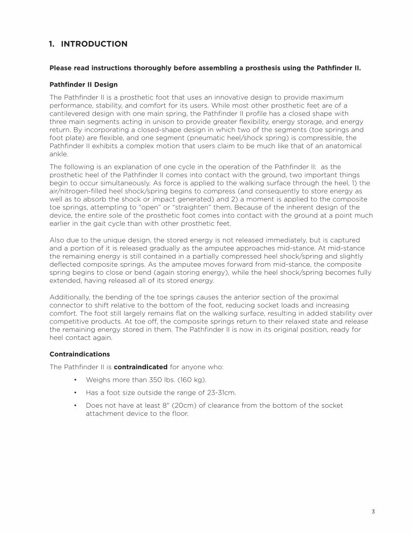
Pathfinder® II Instruction Manual

SECTION PAGE
1 Introduction . . . . . . . . . . . . . . . . . . . . . . . . . . . . . . . . . . . . . . . . . . . . . . . . . 3
2 Pathfinder II Components . . . . . . . . . . . . . . . . . . . . . . . . . . . . . . . . . . . . 4
3 Assembling the Prosthesis . . . . . . . . . . . . . . . . . . . . . . . . . . . . . . . . . . . 5
4 Alignment . . . . . . . . . . . . . . . . . . . . . . . . . . . . . . . . . . . . . . . . . . . . . . . . . . 9
5 Using the Pathfinder II on a Transfemoral Prosthesis . . . . . . . . . . . .18
6 Using the Pathfinder II Transfer Block . . . . . . . . . . . . . . . . . . . . . . . . .18
7 Maintenance . . . . . . . . . . . . . . . . . . . . . . . . . . . . . . . . . . . . . . . . . . . . . . . 20
8 Future Adjustments . . . . . . . . . . . . . . . . . . . . . . . . . . . . . . . . . . . . . . . . . 20
9 Replacement of the Pneumatic Heel Spring . . . . . . . . . . . . . . . . . . . .21
10 Warranty . . . . . . . . . . . . . . . . . . . . . . . . . . . . . . . . . . . . . . . . . . . . . . . . . . 24
2
CONTENTS
3
1. INTRODUCTION
Please read instructions thoroughly before assembling a prosthesis using the Pathfinder II.
Pathfinder II Design
The Pathfinder II is a prosthetic foot that uses an innovative design to provide maximum performance, stability, and comfort for its users . While most other prosthetic feet are of a cantilevered design with one main spring, the Pathfinder II profile has a closed shape with three main segments acting in unison to provide greater flexibility, energy storage, and energy return . By incorporating a closed-shape design in which two of the segments (toe springs and foot plate) are flexible, and one segment (pneumatic heel/shock spring) is compressible, the Pathfinder II exhibits a complex motion that users claim to be much like that of an anatomical ankle .
The following is an explanation of one cycle in the operation of the Pathfinder II: as the prosthetic heel of the Pathfinder II comes into contact with the ground, two important things begin to occur simultaneously . As force is applied to the walking surface through the heel, 1) the air/nitrogen-filled heel shock/spring begins to compress (and consequently to store energy as well as to absorb the shock or impact generated) and 2) a moment is applied to the composite toe springs, attempting to “open” or “straighten” them . Because of the inherent design of the device, the entire sole of the prosthetic foot comes into contact with the ground at a point much earlier in the gait cycle than with other prosthetic feet .
Also due to the unique design, the stored energy is not released immediately, but is captured and a portion of it is released gradually as the amputee approaches mid-stance . At mid-stance the remaining energy is still contained in a partially compressed heel shock/spring and slightly deflected composite springs . As the amputee moves forward from mid-stance, the composite spring begins to close or bend (again storing energy), while the heel shock/spring becomes fully extended, having released all of its stored energy .
Additionally, the bending of the toe springs causes the anterior section of the proximal connector to shift relative to the bottom of the foot, reducing socket loads and increasing comfort . The foot still largely remains flat on the walking surface, resulting in added stability over competitive products . At toe off, the composite springs return to their relaxed state and release the remaining energy stored in them . The Pathfinder II is now in its original position, ready for heel contact again .
Contraindications
The Pathfinder II is contraindicated for anyone who:
• Weighsmorethan350lbs.(160kg).
• Hasafootsizeoutsidetherangeof23-31cm.
• Doesnothaveatleast8"(20cm)ofclearancefromthebottomofthesocket attachment device to the floor .
4
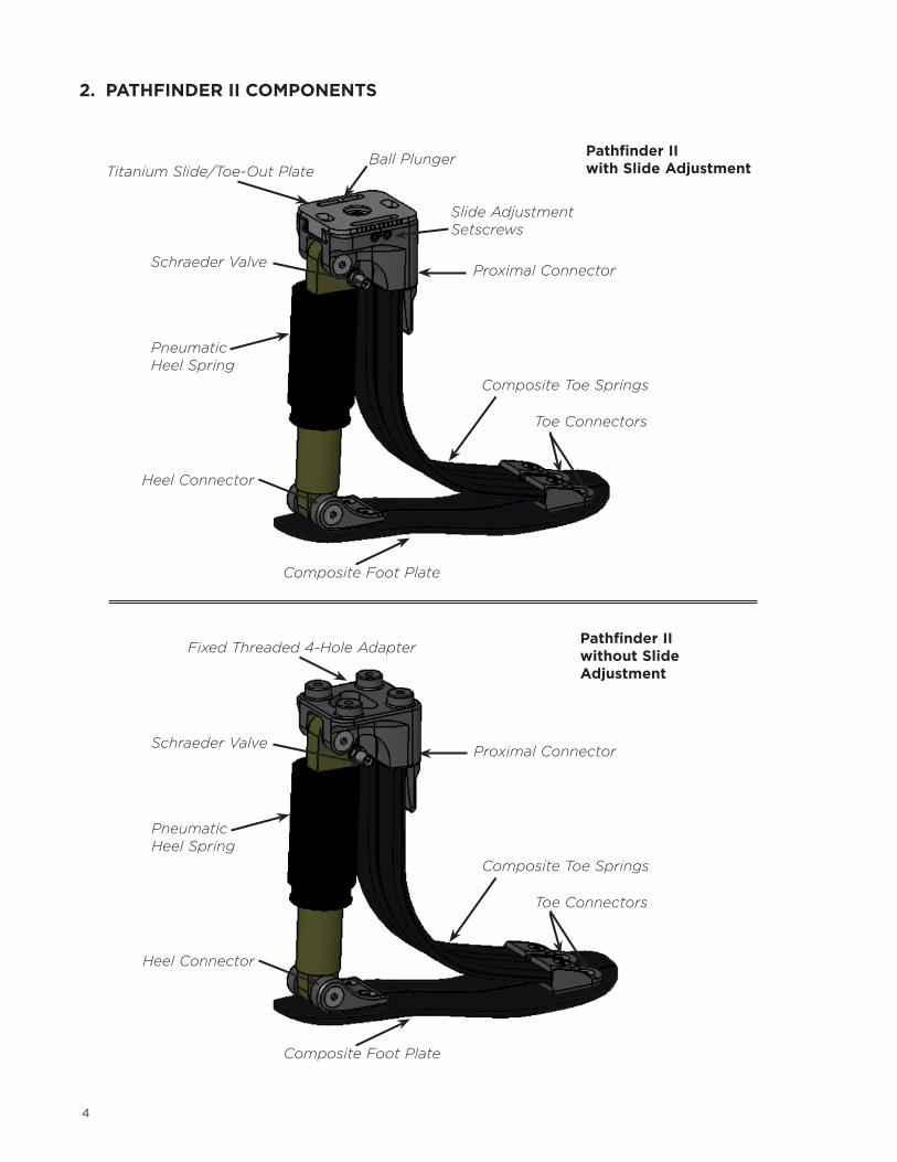
2. PATHFINDER II COMPONENTS
Titanium Slide/Toe-Out PlateBall Plunger
Proximal Connector
Composite Toe Springs
Toe Connectors
Slide Adjustment Setscrews
Schraeder Valve
Pneumatic Heel Spring
Heel Connector
Composite Foot Plate
Pathfinder II with Slide Adjustment
Fixed Threaded 4-Hole Adapter
Proximal Connector
Composite Toe Springs
Toe Connectors
Schraeder Valve
Pneumatic Heel Spring
Heel Connector
Composite Foot Plate
Pathfinder II without Slide Adjustment

5
Since M/L slide adjustment is often required, WillowWood recommends installing a temporary alignment component that provides M/L slide adjustment onto the prosthesis .
When installing additional components onto the prosthesis, keep the following chart in mind so that sufficient space will remain under the components to install the Pathfinder II .
3/4" Heel 18 mm
Standard Pathfinder II
3/8" Heel 10 mm
Standard Pathfinder II
3/4" Heel 18 mm
Low-Profile Pathfinder II
3/8" Heel 10 mm
Low-Profile Pathfinder II
Height of Pathfinder II, Foot Shell, and the Pyramid Adapter
9.5"(24.1cm) 9.8"(24.9cm) 8.5"(21.6cm) 8.8"(22.4cm)
Height of Pathfinder II, Foot Shell, and the Pyramid Receiver
9.1"(23.1cm) 9.5"(24.1cm) 8.1"(20.6cm) 8.5"(21.6cm)
Height of Pathfinder II, Foot Shell, and either the Threaded 4-Hole Adapter or the Through 4-Hole Adapter with Valve
8.7"(22.1cm) 9.1"(23.1cm) 7.7"(19.6cm) 8.1"(20.6cm)
Height of Pathfinder II, Foot Shell, and the Fixed Threaded 4-Hole Adapter (no slide adjustment)
8.3"(21.1cm) 8.7"(22.1cm) 7.3"(18.5cm) 7.7"(19.6cm)
3. ASSEMBLING THE PROSTHESIS
6
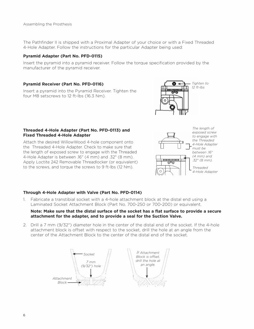
The Pathfinder II is shipped with a Proximal Adapter of your choice or with a Fixed Threaded 4-Hole Adapter . Follow the instructions for the particular Adapter being used:
Pyramid Adapter (Part No. PFD-0115)
Insert the pyramid into a pyramid receiver . Follow the torque specification provided by the manufacturer of the pyramid receiver .
Pyramid Receiver (Part No. PFD-0116)
Insert a pyramid into the Pyramid Receiver . Tighten the four M8 setscrews to 12 ft-lbs (16 .3 Nm) .
Threaded 4-Hole Adapter (Part No. PFD-0113) and Fixed Threaded 4-Hole Adapter
Attach the desired WillowWood 4-hole component onto the Threaded 4-Hole Adapter . Check to make sure that the length of exposed screw to engage with the Threaded 4-HoleAdapterisbetween.16"(4mm)and.32"(8mm).Apply Loctite 242 Removable Threadlocker (or equivalent) to the screws, and torque the screws to 9 ft-lbs (12 Nm) .
Through 4-Hole Adapter with Valve (Part No. PFD-0114)
1 . Fabricate a transtibial socket with a 4-hole attachment block at the distal end using a Laminated Socket Attachment Block (Part No . 700-250 or 700-200) or equivalent .
Note: Make sure that the distal surface of the socket has a flat surface to provide a secure attachment for the adapter, and to provide a seal for the Suction Valve.
2. Drilla7mm(9/32")diameterholeinthecenterofthedistalendofthesocket.Ifthe4-holeattachment block is offset with respect to the socket, drill the hole at an angle from the center of the Attachment Block to the center of the distal end of the socket .
Assembling the Prosthesis
Tighten to 12 ft-lbs
The length of exposed screw to engage with the Threaded 4-Hole Adapter must be between .16" (4 mm) and .32" (8 mm).
Threaded 4-Hole Adapter
Socket
7 mm (9/32") hole
Attachment Block
If Attachment Block is offset, drill the hole at
an angle.
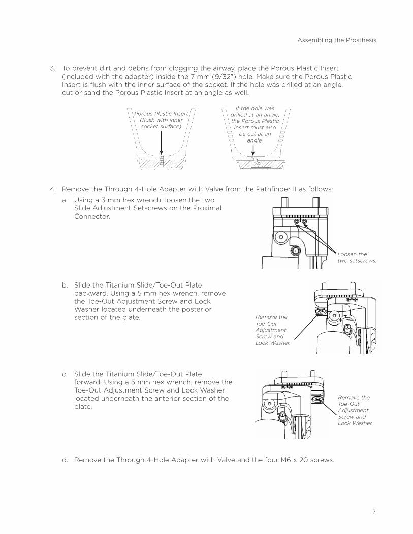
3 . To prevent dirt and debris from clogging the airway, place the Porous Plastic Insert (includedwiththeadapter)insidethe7mm(9/32")hole.MakesurethePorousPlastic Insert is flush with the inner surface of the socket . If the hole was drilled at an angle, cut or sand the Porous Plastic Insert at an angle as well .
4 . Remove the Through 4-Hole Adapter with Valve from the Pathfinder II as follows:
a . Using a 3 mm hex wrench, loosen the two Slide Adjustment Setscrews on the Proximal Connector .
b . Slide the Titanium Slide/Toe-Out Plate backward . Using a 5 mm hex wrench, remove the Toe-Out Adjustment Screw and Lock Washer located underneath the posterior section of the plate .
c . Slide the Titanium Slide/Toe-Out Plate forward . Using a 5 mm hex wrench, remove the Toe-Out Adjustment Screw and Lock Washer located underneath the anterior section of the plate .
d . Remove the Through 4-Hole Adapter with Valve and the four M6 x 20 screws .
7
Assembling the Prosthesis
Porous Plastic Insert (flush with inner socket surface)
If the hole was drilled at an angle, the Porous Plastic Insert must also
be cut at an angle.
Loosen the two setscrews.
Remove the Toe-Out Adjustment Screw and Lock Washer.
Remove the Toe-Out Adjustment Screw and Lock Washer.
8
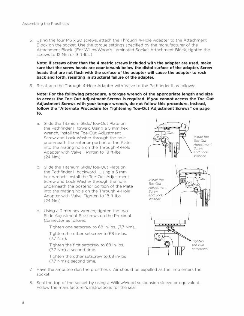
5 . Using the four M6 x 20 screws, attach the Through 4-Hole Adapter to the Attachment Block on the socket . Use the torque settings specified by the manufacturer of the Attachment Block . (For WillowWood’s Laminated Socket Attachment Block, tighten the screws to 12 Nm or 9 ft-lbs .)
Note: If screws other than the 4 metric screws included with the adapter are used, make sure that the screw heads are countersunk below the distal surface of the adapter. Screw heads that are not flush with the surface of the adapter will cause the adapter to rock back and forth, resulting in structural failure of the adapter.
6 . Re-attach the Through 4-Hole Adapter with Valve to the Pathfinder II as follows:
Note: For the following procedure, a torque wrench of the appropriate length and size to access the Toe-Out Adjustment Screws is required. If you cannot access the Toe-Out Adjustment Screws with your torque wrench, do not follow this procedure. Instead, follow the “Alternate Procedure for Tightening Toe-Out Adjustment Screws” on page 16.
a . Slide the Titanium Slide/Toe-Out Plate on the Pathfinder II forward . Using a 5 mm hex wrench, install the Toe-Out Adjustment Screw and Lock Washer through the hole underneath the anterior portion of the Plate into the mating hole on the Through 4-Hole Adapter with Valve . Tighten to 18 ft-lbs (24 Nm) .
b . Slide the Titanium Slide/Toe-Out Plate on the Pathfinder II backward . Using a 5 mm hex wrench, install the Toe-Out Adjustment Screw and Lock Washer through the hole underneath the posterior portion of the Plate into the mating hole on the Through 4-Hole Adapter with Valve . Tighten to 18 ft-lbs (24 Nm) .
c . Using a 3 mm hex wrench, tighten the two Slide Adjustment Setscrews on the Proximal Connector as follows:
Tighten one setscrew to 68 in-lbs . (7 .7 Nm) .
Tighten the other setscrew to 68 in-lbs . (7 .7 Nm) .
Tighten the first setscrew to 68 in-lbs . (7 .7 Nm) a second time .
Tighten the other setscrew to 68 in-lbs (7 .7 Nm) a second time .
7 . Have the amputee don the prosthesis . Air should be expelled as the limb enters the socket .
8 . Seal the top of the socket by using a WillowWood suspension sleeve or equivalent . Follow the manufacturer's instructions for the seal .
Assembling the Prosthesis
Install the Toe-Out Adjustment Screw and Lock Washer.
Install the Toe-Out Adjustment Screw and Lock Washer.
Tighten the two setscrews.
9
In order for the amputee to obtain maximum performance from the Pathfinder II, certain alignment principals must be applied . These principles differ somewhat from standard alignment theory.
IMPORTANT: Before beginning the alignment process, address any issues with socket comfort. The amputee must be able to focus entirely on alignment issues without being distracted by socket discomfort.
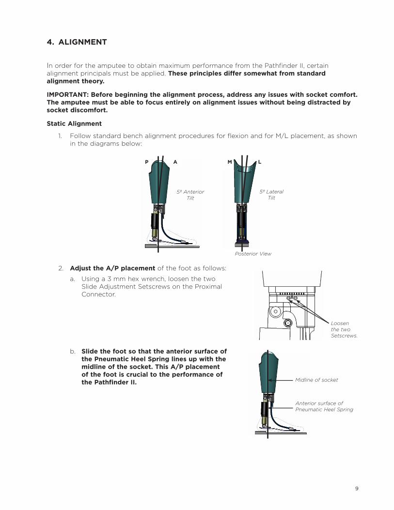
Static Alignment
1 . Follow standard bench alignment procedures for flexion and for M/L placement, as shown in the diagrams below:
2 . Adjust the A/P placement of the foot as follows:
a . Using a 3 mm hex wrench, loosen the two Slide Adjustment Setscrews on the Proximal Connector .
b . Slide the foot so that the anterior surface of the Pneumatic Heel Spring lines up with the midline of the socket. This A/P placement of the foot is crucial to the performance of the Pathfinder II.
4. ALIGNMENT
Posterior View
P A M L
5º Anterior Tilt
5º Lateral Tilt
Loosen the two Setscrews.
Midline of socket
Anterior surface of Pneumatic Heel Spring
10
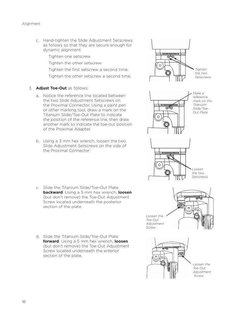
c . Hand-tighten the Slide Adjustment Setscrews as follows so that they are secure enough for dynamic alignment:
Tighten one setscrew .
Tighten the other setscrew .
Tighten the first setscrew a second time .
Tighten the other setscrew a second time .
3 . Adjust Toe-Out as follows:
a . Notice the reference line located between the two Slide Adjustment Setscrews on the Proximal Connector . Using a paint pen or other marking tool, draw a mark on the Titanium Slide/Toe-Out Plate to indicate the position of the reference line, then draw another mark to indicate the toe-out position of the Proximal Adapter .
b . Using a 3 mm hex wrench, loosen the two Slide Adjustment Setscrews on the side of the Proximal Connector .
c . Slide the Titanium Slide/Toe-Out Plate backward . Using a 5 mm hex wrench, loosen (but don’t remove) the Toe-Out Adjustment Screw located underneath the posterior section of the plate .
d . Slide the Titanium Slide/Toe-Out Plate forward . Using a 5 mm hex wrench, loosen (but don’t remove) the Toe-Out Adjustment Screw located underneath the anterior section of the plate .
Tighten the two Setscrews.
Make a reference mark on the Titanium Slide/Toe-Out Plate.
Loosen the two Setscrews.
Loosen the Toe-Out Adjustment Screw.
Loosen the Toe-Out Adjustment Screw.
Alignment
11
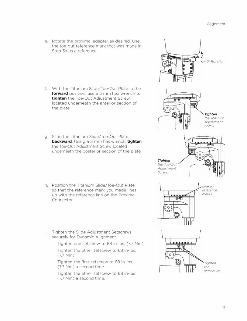
e . Rotate the proximal adapter as desired . Use the toe-out reference mark that was made in Step 3a as a reference .
f . With the Titanium Slide/Toe-Out Plate in the forward position, use a 5 mm hex wrench to tighten the Toe-Out Adjustment Screw located underneath the anterior section of the plate .
g . Slide the Titanium Slide/Toe-Out Plate backward . Using a 5 mm hex wrench, tighten the Toe-Out Adjustment Screw located underneath the posterior section of the plate .
h . Position the Titanium Slide/Toe-Out Plate so that the reference mark you made lines up with the reference line on the Proximal Connector .
i . Tighten the Slide Adjustment Setscrews securelyforDynamicAlignment.
Tighten one setscrew to 68 in-lbs . (7 .7 Nm) .
Tighten the other setscrew to 68 in-lbs . (7 .7 Nm) .
Tighten the first setscrew to 68 in-lbs . (7 .7 Nm) a second time .
Tighten the other setscrew to 68 in-lbs (7 .7 Nm) a second time .
+/-10° Rotation
Alignment
Tighten the Toe-Out Adjustment Screw.
Tighten the Toe-Out Adjustment Screw.
Line up reference marks.
Tighten the setscrews.
12
4 . Make angular adjustments to the socket to correct any medial or lateral lean of the Composite Toe Springs .
5 . Adjust M/L slide using the alignment component installed on the prosthesis .
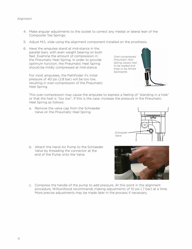
6 . Have the amputee stand at mid-stance in the parallel bars, with even weight bearing on both feet . Examine the amount of compression in the Pneumatic Heel Spring . In order to provide optimum function, the Pneumatic Heel Spring should be mildly compressed at mid-stance .
For most amputees, the Pathfinder II’s initial pressure of 40 psi (2 .8 bar) will be too low, resulting in over-compression of the Pneumatic Heel Spring .
This over-compression may cause the amputee to express a feeling of “standing in a hole” or that the heel is “too low” . If this is the case, increase the pressure in the Pneumatic Heel Spring as follows:
a . Remove the valve cap from the Schraeder Valve on the Pneumatic Heel Spring .
b . Attach the Hand Air Pump to the Schraeder Valve by threading the connector at the end of the Pump onto the Valve .
c . Compress the handle of the pump to add pressure . At this point in the alignment procedure, WillowWood recommends making adjustments of 10 psi ( .7 bar) at a time . More precise adjustments may be made later in the process if necessary .
Alignment
Schraeder Valve
Over-compressed Pneumatic Heel Spring causes heel to be loaded and knee to be forced backwards.
13
Alignment
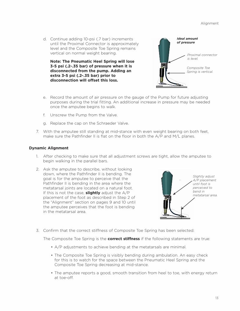
d . Continue adding 10-psi ( .7 bar) increments until the Proximal Connector is approximately level and the Composite Toe Spring remains vertical on normal weight bearing .
Note: The Pneumatic Heel Spring will lose 3-5 psi (.2-.35 bar) of pressure when it is disconnected from the pump. Adding an extra 3-5 psi (.2-.35 bar) prior to disconnection will offset this loss.
e . Record the amount of air pressure on the gauge of the Pump for future adjusting purposes during the trial fitting . An additional increase in pressure may be needed once the amputee begins to walk .
f . Unscrew the Pump from the Valve .
g . Replace the cap on the Schraeder Valve .
7 . With the amputee still standing at mid-stance with even weight bearing on both feet, make sure the Pathfinder II is flat on the floor in both the A/P and M/L planes .
Dynamic Alignment
1 . After checking to make sure that all adjustment screws are tight, allow the amputee to begin walking in the parallel bars .
2 . Ask the amputee to describe, without looking down, where the Pathfinder II is bending . The goal is for the amputee to perceive that the Pathfinder II is bending in the area where the metatarsal joints are located on a natural foot . If this is not the case, slightly adjust the A/P placement of the foot as described in Step 2 of the “Alignment” section on pages 9 and 10 until the amputee perceives that the foot is bending in the metatarsal area .
3 . Confirm that the correct stiffness of Composite Toe Spring has been selected:
The Composite Toe Spring is the correct stiffness if the following statements are true:
•A/Padjustmentstoachievebendingatthemetatarsalsareminimal.
•TheCompositeToeSpringisvisiblybendingduringambulation.Aneasycheckfor this is to watch for the space between the Pneumatic Heel Spring and the Composite Toe Spring decreasing at mid-stance .
•Theamputeereportsagood,smoothtransitionfromheeltotoe,withenergyreturnat toe-off .
Proximal connector is level.
Composite Toe Spring is vertical.
Ideal amount of pressure
Slightly adjust A/P placement until foot is perceived to bend in metatarsal area.

14
The Composite Toe Spring is too stiff for the amputee if the following statements are true:
•ThePathfinderIImustbemovedsignificantlyposterior(orthesocketmustbemoved significantly anterior) in order to achieve rocking over the toe .
•ThereisnovisiblebendingoftheCompositeToeSpringduringambulation.
The Composite Toe Spring is too soft for the amputee if the following statements are true:
•ThePathfinderIImustbemovedsignificantlyanterior(orthesocketmustbemoved significantly posterior) in order to prevent falling across the toe .
•Whilestandingatmid-stance,theamputeereportsafeelingoffallingforward.
If the Composite Toe Spring is either too stiff or too soft, please call a WillowWood certified prosthetist at 877-699-2574 or 740-869-3377 for assistance in changing the spring.
4 . The A/P placement changes made in Step 4 typically require some adjustment of the Pneumatic Heel Spring pressure:
a . Remove the valve cap from the Schraeder Valve on the Pneumatic Heel Spring and attach the Hand Air Pump as shown on page 12 .
b . Adjust the pressure accordingly:
• IfthePathfinderIIwasmovedintheanteriordirection(orthesocketwasmovedinthe posterior direction), an increase in the pressure is usually required . Increase the pressure by compressing the handle of the pump .
• IfthePathfinderIIwasmovedintheposteriordirection(orthesocketwasmovedin the anterior direction), a decrease in the pressure is usually required . Reduce the pressure by pressing the Pressure Release Button below the gauge on the Hand Air Pump .
WillowWood recommends making initial adjustments of 10 psi ( .7 bar) at a time, followed by more precise adjustments if necessary . Continue adjusting the air pressure, as shown in Step d on page 13, until the amputee feels that the heel compression is normal .
d . Record the amount of air pressure on the gauge of the Pump .
e . Unscrew the Pump from the Valve .
f . Replace the cap on the Schraeder Valve .
Alignment
15
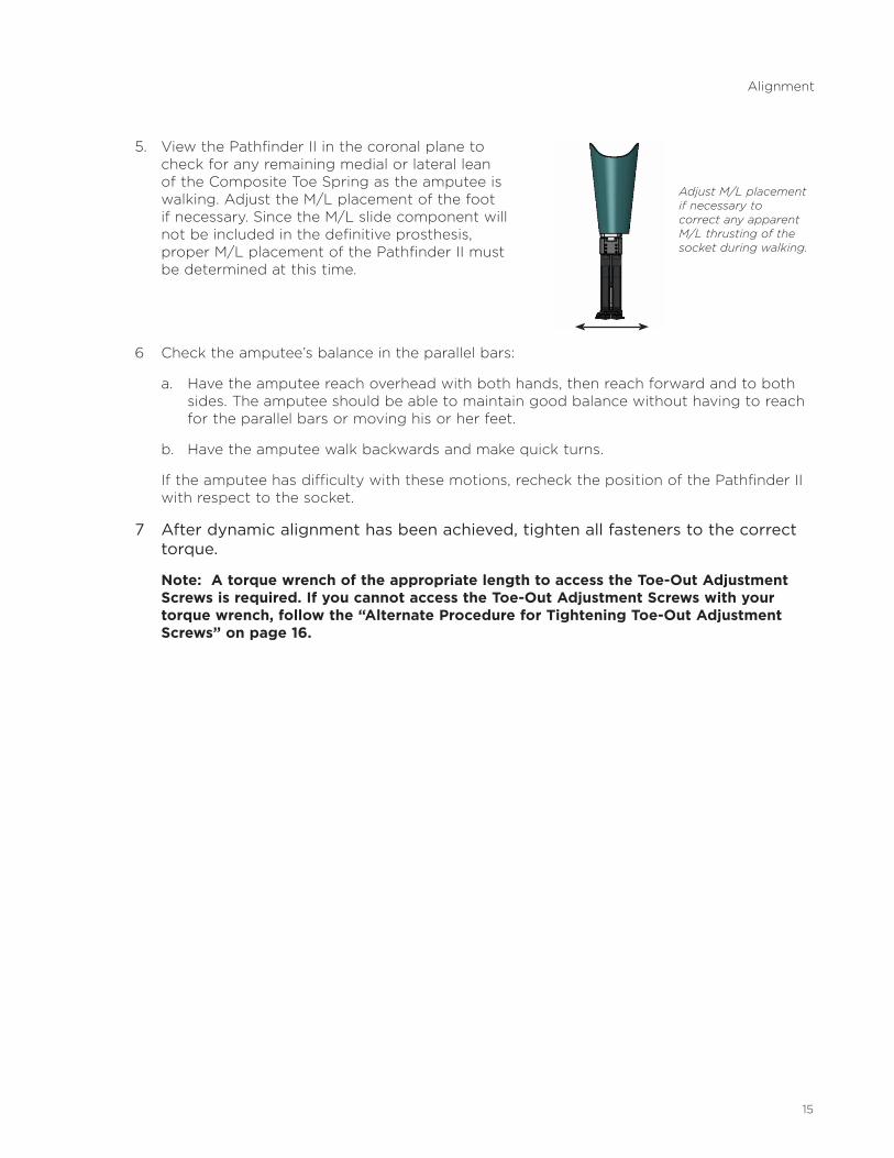
5 . View the Pathfinder II in the coronal plane to check for any remaining medial or lateral lean of the Composite Toe Spring as the amputee is walking . Adjust the M/L placement of the foot if necessary . Since the M/L slide component will not be included in the definitive prosthesis, proper M/L placement of the Pathfinder II must be determined at this time .
6 Check the amputee’s balance in the parallel bars:
a . Have the amputee reach overhead with both hands, then reach forward and to both sides . The amputee should be able to maintain good balance without having to reach for the parallel bars or moving his or her feet .
b . Have the amputee walk backwards and make quick turns .
If the amputee has difficulty with these motions, recheck the position of the Pathfinder II with respect to the socket .
7 After dynamic alignment has been achieved, tighten all fasteners to the correct torque.
Note: A torque wrench of the appropriate length to access the Toe-Out Adjustment Screws is required. If you cannot access the Toe-Out Adjustment Screws with your torque wrench, follow the “Alternate Procedure for Tightening Toe-Out Adjustment Screws” on page 16.
Adjust M/L placement if necessary to correct any apparent M/L thrusting of the socket during walking.
Alignment
16
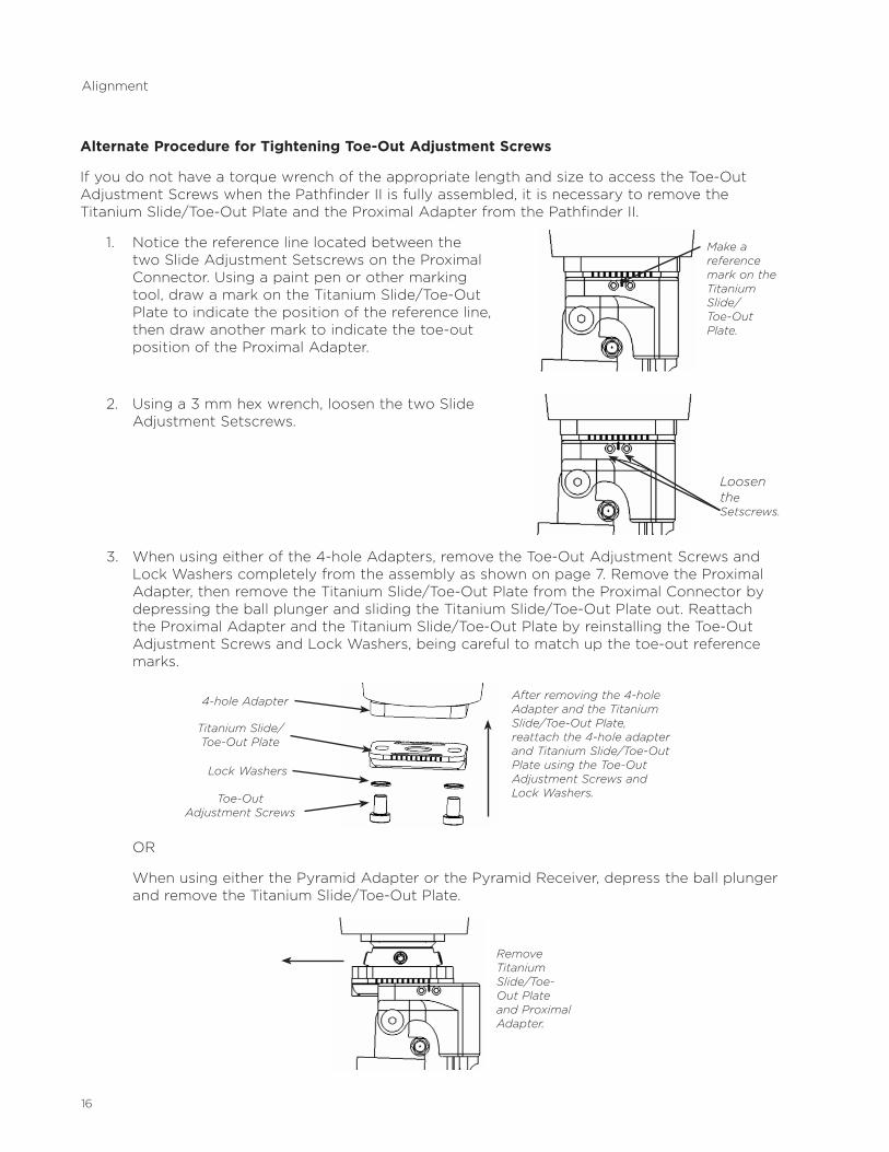
Alternate Procedure for Tightening Toe-Out Adjustment Screws
IfyoudonothaveatorquewrenchoftheappropriatelengthandsizetoaccesstheToe-OutAdjustment Screws when the Pathfinder II is fully assembled, it is necessary to remove the Titanium Slide/Toe-Out Plate and the Proximal Adapter from the Pathfinder II .
1 . Notice the reference line located between the two Slide Adjustment Setscrews on the Proximal Connector . Using a paint pen or other marking tool, draw a mark on the Titanium Slide/Toe-Out Plate to indicate the position of the reference line, then draw another mark to indicate the toe-out position of the Proximal Adapter .
2 . Using a 3 mm hex wrench, loosen the two Slide Adjustment Setscrews .
3 . When using either of the 4-hole Adapters, remove the Toe-Out Adjustment Screws and Lock Washers completely from the assembly as shown on page 7 . Remove the Proximal Adapter, then remove the Titanium Slide/Toe-Out Plate from the Proximal Connector by depressing the ball plunger and sliding the Titanium Slide/Toe-Out Plate out . Reattach the Proximal Adapter and the Titanium Slide/Toe-Out Plate by reinstalling the Toe-Out Adjustment Screws and Lock Washers, being careful to match up the toe-out reference marks .
OR
When using either the Pyramid Adapter or the Pyramid Receiver, depress the ball plunger and remove the Titanium Slide/Toe-Out Plate .
Make a reference mark on the Titanium Slide/ Toe-Out Plate.
After removing the 4-hole Adapter and the Titanium Slide/Toe-Out Plate, reattach the 4-hole adapter and Titanium Slide/Toe-Out Plate using the Toe-Out Adjustment Screws and Lock Washers.
4-hole Adapter
Titanium Slide/ Toe-Out Plate
Toe-Out Adjustment Screws
Lock Washers
Alignment
Loosen the Setscrews.
Remove Titanium Slide/Toe-Out Plate and Proximal Adapter.
17
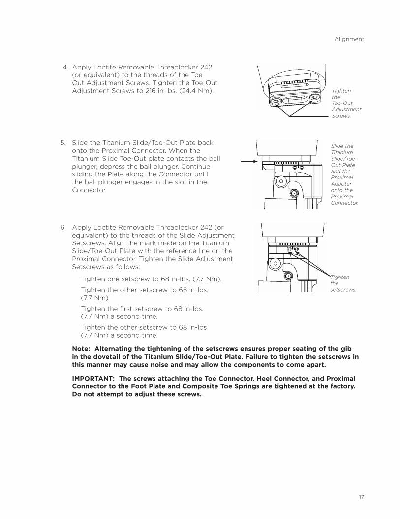
4 . Apply Loctite Removable Threadlocker 242 (or equivalent) to the threads of the Toe-Out Adjustment Screws . Tighten the Toe-Out Adjustment Screws to 216 in-lbs . (24 .4 Nm) .
5 . Slide the Titanium Slide/Toe-Out Plate back onto the Proximal Connector . When the Titanium Slide Toe-Out plate contacts the ball plunger, depress the ball plunger . Continue sliding the Plate along the Connector until the ball plunger engages in the slot in the Connector .
6 . Apply Loctite Removable Threadlocker 242 (or equivalent) to the threads of the Slide Adjustment Setscrews . Align the mark made on the Titanium Slide/Toe-Out Plate with the reference line on the Proximal Connector . Tighten the Slide Adjustment Setscrews as follows:
Tighten one setscrew to 68 in-lbs . (7 .7 Nm) .
Tighten the other setscrew to 68 in-lbs . (7 .7 Nm)
Tighten the first setscrew to 68 in-lbs . (7 .7 Nm) a second time .
Tighten the other setscrew to 68 in-lbs (7 .7 Nm) a second time .
Note: Alternating the tightening of the setscrews ensures proper seating of the gib in the dovetail of the Titanium Slide/Toe-Out Plate. Failure to tighten the setscrews in this manner may cause noise and may allow the components to come apart.
IMPORTANT: The screws attaching the Toe Connector, Heel Connector, and Proximal Connector to the Foot Plate and Composite Toe Springs are tightened at the factory. Do not attempt to adjust these screws.
Slide the Titanium Slide/Toe- Out Plate and the Proximal Adapter onto the Proximal Connector.
Alignment
Tighten the Toe-Out Adjustment Screws.
Tighten the setscrews.
18
5. USING THE PATHFINDER II ON A TRANSFEMORAL PROSTHESIS
All of the above fitting principles also apply to the use of the Pathfinder II on a transfemoral prosthesis . With a transfemoral prosthesis, however, it is even more important that the Proximal Connector be parallel to the floor during mild weight bearing at mid-stance . Any significant anterior leaning of the prosthesis at mid-stance will have a negative effect on knee stability . If the prosthesis is aligned properly, the Pathfinder II will increase the floor reaction force and complement the knee in maintaining knee extension . This works especially well with hydraulically controlled knees .
6. USING THE PATHFINDER II TRANSFER BLOCK
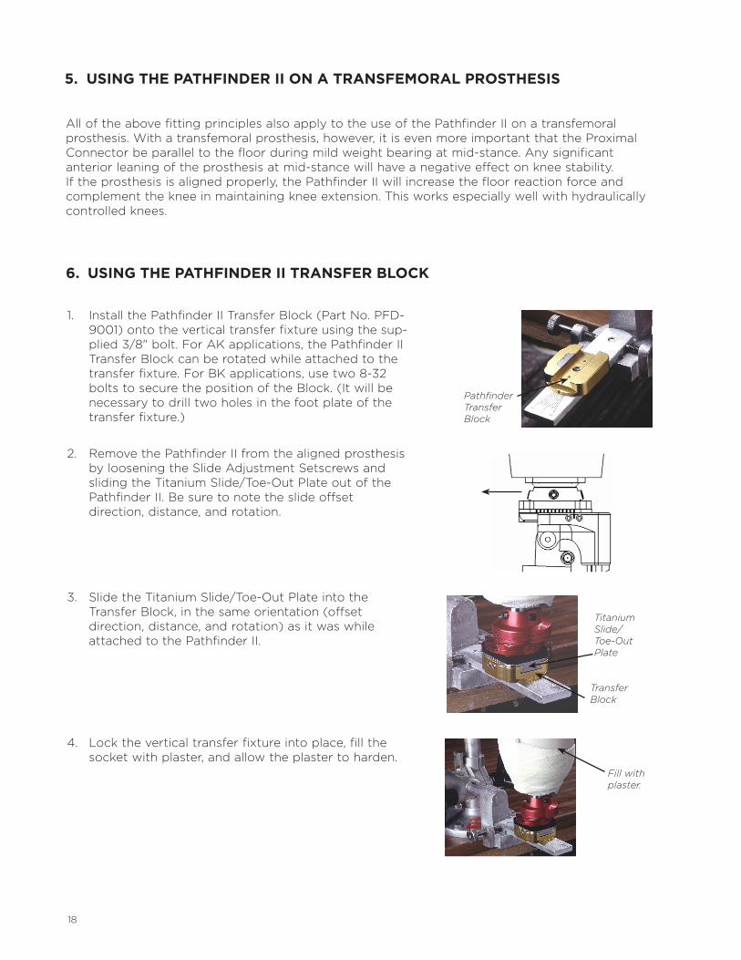
1. InstallthePathfinderIITransferBlock(PartNo.PFD-9001) onto the vertical transfer fixture using the sup-plied3/8"bolt.ForAKapplications,thePathfinderIITransfer Block can be rotated while attached to the transferfixture.ForBKapplications,usetwo8-32bolts to secure the position of the Block . (It will be necessary to drill two holes in the foot plate of the transfer fixture .)
2 . Remove the Pathfinder II from the aligned prosthesis by loosening the Slide Adjustment Setscrews and sliding the Titanium Slide/Toe-Out Plate out of the Pathfinder II . Be sure to note the slide offset direction, distance, and rotation .
3 . Slide the Titanium Slide/Toe-Out Plate into the Transfer Block, in the same orientation (offset direction, distance, and rotation) as it was while attached to the Pathfinder II .
4 . Lock the vertical transfer fixture into place, fill the socket with plaster, and allow the plaster to harden .
Pathfinder Transfer Block
Titanium Slide/ Toe-Out Plate
Transfer Block
Fill with plaster.
19
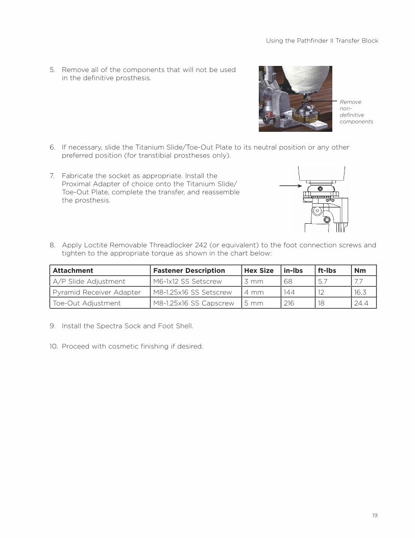
5 . Remove all of the components that will not be used in the definitive prosthesis .
6 . If necessary, slide the Titanium Slide/Toe-Out Plate to its neutral position or any other preferred position (for transtibial prostheses only) .
7 . Fabricate the socket as appropriate . Install the Proximal Adapter of choice onto the Titanium Slide/Toe-Out Plate, complete the transfer, and reassemble the prosthesis .
8 . Apply Loctite Removable Threadlocker 242 (or equivalent) to the foot connection screws and tighten to the appropriate torque as shown in the chart below:
Attachment Fastener Description Hex Size in-lbs ft-lbs NmA/P Slide Adjustment M6-1x12 SS Setscrew 3 mm 68 5 .7 7 .7
Pyramid Receiver Adapter M8-1 .25x16 SS Setscrew 4 mm 144 12 16 .3
Toe-Out Adjustment M8-1 .25x16 SS Capscrew 5 mm 216 18 24 .4
9 . Install the Spectra Sock and Foot Shell .
10 . Proceed with cosmetic finishing if desired .
Remove non- definitive components
Using the Pathfinder II Transfer Block
20
7. MAINTENANCE
Clean the Pathfinder II periodically with body soap and water .
If you expose the Pathfinder II to sand or salt water:
•RemovethefootshellandSpectraSock.
•Cleanoutthesand.
•CleanthePathfinderII,thefootshell,andtheSpectraSockwithbodysoapandwater.
•AllowthefootshellandSpectraSocktodrybeforereassembling.
Inspect the following items during an annual check-up:
1 . Visually inspect the foot for structural integrity .
2 . Confirm that the adjustment screws are tightened to the appropriate torque . Apply Loctite Removable Threadlocker 242 (or equivalent) if necessary .
3 . Replace the Foot Shell and Spectra Sock if they are worn or damaged .
4 . No lubrication is necessary .
8. FUTURE ADJUSTMENTS
It is normal for an amputee’s activity level to increase after receiving the Pathfinder II . If this happens:
• thefootmayneedtobeoutset.
• theamputeemayaskformoretoeresistance.Inanticipationofthis,besuretoleavesome A/P slide capability after the initial fitting .
• angularchangesinthecoronalplanemayberequiredtocorrectavarusthrustthat commonly occurs after the amputee has worn the Pathfinder II for a while .
21
9. REPLACEMENT OF THE PNEUMATIC HEEL SPRING
Perform the following procedure to replace a Pneumatic Heel Spring (PHS) that has developed a drop in performance, or to replace the PHS Thrust Bearings or Rubber O-Rings .
Note: two sizes of replacement Pneumatic Heel Springs are available. Order PFD-1101 for use in the standard Pathfinder, and PFD-1104 for use in the Low Profile Pathfinder.
Tools needed: One 4 mm hex wrench One 3 mm hex wrench
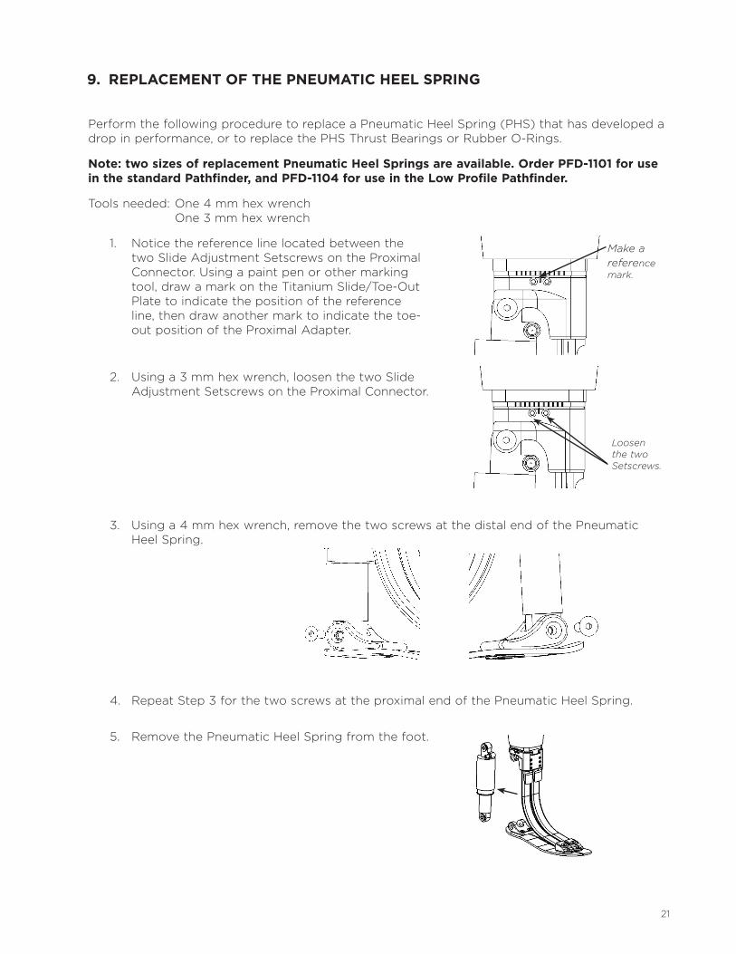
1 . Notice the reference line located between the two Slide Adjustment Setscrews on the Proximal Connector . Using a paint pen or other marking tool, draw a mark on the Titanium Slide/Toe-Out Plate to indicate the position of the reference line, then draw another mark to indicate the toe-out position of the Proximal Adapter .
2 . Using a 3 mm hex wrench, loosen the two Slide Adjustment Setscrews on the Proximal Connector .
3 . Using a 4 mm hex wrench, remove the two screws at the distal end of the Pneumatic Heel Spring .
4 . Repeat Step 3 for the two screws at the proximal end of the Pneumatic Heel Spring .
5 . Remove the Pneumatic Heel Spring from the foot .
Make a reference mark.
Loosen the two Setscrews.
22
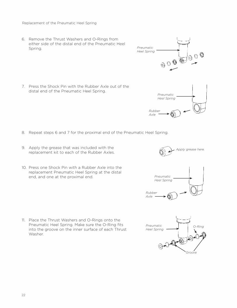
6 . Remove the Thrust Washers and O-Rings from either side of the distal end of the Pneumatic Heel Spring .
7 . Press the Shock Pin with the Rubber Axle out of the distal end of the Pneumatic Heel Spring .
8 . Repeat steps 6 and 7 for the proximal end of the Pneumatic Heel Spring .
9 . Apply the grease that was included with the replacement kit to each of the Rubber Axles .
10 . Press one Shock Pin with a Rubber Axle into the replacement Pneumatic Heel Spring at the distal end, and one at the proximal end .
11 . Place the Thrust Washers and O-Rings onto the Pneumatic Heel Spring . Make sure the O-Ring fits into the groove on the inner surface of each Thrust Washer .
Replacement of the Pneumatic Heel Spring
Pneumatic Heel Spring
Rubber Axle
Pneumatic Heel Spring
Apply grease here.
Rubber Axle
Pneumatic Heel Spring
Pneumatic Heel Spring
O-Ring
Groove
23
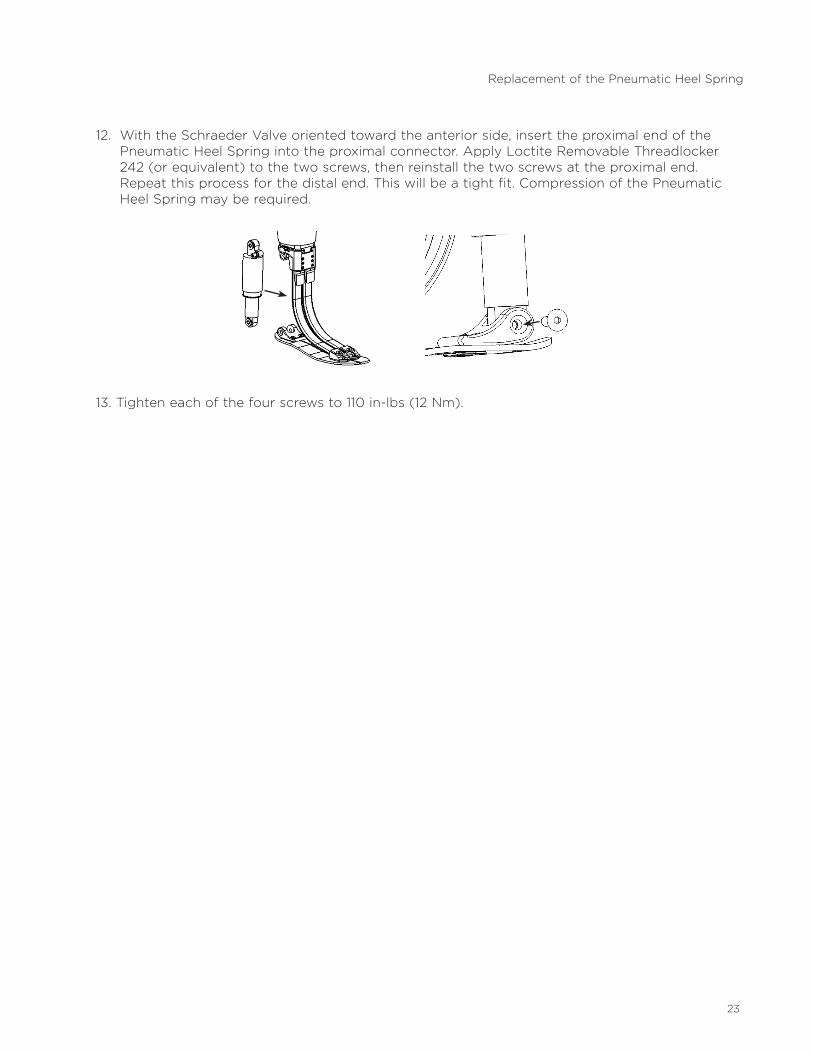
12 . With the Schraeder Valve oriented toward the anterior side, insert the proximal end of the Pneumatic Heel Spring into the proximal connector . Apply Loctite Removable Threadlocker 242 (or equivalent) to the two screws, then reinstall the two screws at the proximal end . Repeat this process for the distal end . This will be a tight fit . Compression of the Pneumatic Heel Spring may be required .
13 . Tighten each of the four screws to 110 in-lbs (12 Nm) .
Replacement of the Pneumatic Heel Spring

24
10. WARRANTY
WillowWood warrants each Pathfinder II from the date of invoice for a period of 36 months against defects in materials and workmanship . A Pathfinder II returned during the warranty period will be evaluated and repaired or replaced at WillowWood’s discretion .
Use of the Pathfinder II for amputees whose adjusted body weight is more than 350 lbs . (160 kg) is against WillowWood’s recommendation and will void the 36-month warranty . Adjusted body weight is defined as the weight of the amputee plus any loads carried by the amputee .
The foot shell is warranted from the date of invoice for a period of 9 months against defects in materials and workmanship .
The Spectra Sock and hand pump are warranted from the date of invoice for a period of 6 months against defects in materials and workmanship .
Alteration of any of the Pathfinder II components, or replacement of any Pathfinder II components with components not supplied by WillowWood, will void the warranty.
Warranty DisclaimerWillowWood warrants that each product manufactured will, at the time of delivery, be of workmanlike quality and substantially free of defects . WILLOWWOOD MAKES NO OTHER WARRANTY, IMPLIED, OR EXPRESSED, AND MAKES NO WARRANTY OF MERCHANTABILITY OR FITNESS FOR A PARTICULAR PURPOSE. This warranty shall terminate immediately upon an action to combine our products with other materials or in any manner to change the nature of our products . The sole remedy is replacement of the products or credit for the products . WillowWood’s liability shall not exceed the purchase price of the product . WillowWood shall not be liable for any indirect, incidental, or consequential damage.
WillowWood Retention of RightsWillowWood retains all intellectual property rights reflected or incorporated in its physical products, regardless of the transfer of the physical products to another party or parties.

25
The Ohio Willow Wood Company15441SciotoDarbyRoadMt . Sterling, OH 43143phone 740 .869 .3377 / 800 .848 .4930fax 740 .869 .4374 www .willowwoodco .com
Ohio Willow Wood Company B .VKeizersgracht62/641015 CS AmsterdamThe NetherlandsPatent www .willowwoodco .com/ education-and-resources/patents
PN-1363-J 21 OCT 2013