Embed Size (px)
Citation preview

Pathfinder Radar ScannersOwner’s Handbook
Document number: 81154_7Date: 1st March 2004


i Pathfinder Radar Scanners
Pathfinder Radar ScannersOwners Handbook
March 2004
Intended UseThe scanner units detailed in this handbook form part of navigational radar systems intended for light marine use. These radar systems are only an aid to navigation.
WARNING: The 4D radome scanner connected to an SL70, SL70 PLUS or SL70RC PLUS 7" LCD display unit DOES NOT conform to the EU directive 95/5/EC, therefore such a system cannot be installed on a vessel within the EU.
Safety NoticesThis radar equipment must be installed and operated in accordance with the instructions contained in this manual. Failure to do so can result in personal injury and/or navigational inaccuracies. In particular:
1. High Voltage. The scanner unit contains high voltages. Adjustments require specialized service procedures and tools only available to qualified service technicians – there are no user serviceable parts or adjustments. The operator should never remove the scanner unit internal covers or attempt to service the equipment.
2. Electromagnetic Energy. The radar scanner transmits electromagnetic energy. It is important that the radar is turned off whenever personnel are required to come close to the scanner to perform work on the scanner assembly or associated equipment.
It is recommended that the radar scanner is mounted out of range of personnel (above head height).
Do not look directly at the antenna at close range as your eyes are the most sensitive part of the body to electromagnetic energy.
When properly installed and operated, the use of this radar will conform to the requirements of ANSI/IEEE C95.1-1992 Standard for Safety Levels with Respect to Human Exposure to Radio Frequency Electromagnetic Fields, 3 Hz to 300 GHz and
ii Pathfinder Radar Scanners
NRPB, Board Statement on Restrictions on Human Exposure to Static and Time Varying Electromagnetic Fields and Radiation, Doc NRPB, No. 5 (1993).
3. Navigation Aid. This radar unit is only an aid to navigation. Its accuracy can be affected by many factors, including equipment failure or defects, environmental conditions, and improper handling or use. It is the user’s responsibility to exercise common prudence and navigational judgements. This radar unit should not be relied upon as a substitute for such prudence and judgement.
Raymarine products are supported by a network of Authorized Service Representatives. For information on Raymarine products and services, contact either of the following:
United States Raymarine Inc.Recreational Products22 Cotton Road, Unit DNashuaNH 03063-4219, USATelephone +1 603 881 5200Fax +1 603 864 4756www.raymarine.com
Europe Raymarine LimitedAnchorage ParkPortsmouthHampshire PO3 5TDEnglandTelephone +44 (0)23 9269 3611Fax +44 (0)23 9269 4642www.raymarine.com
Copyright © Raymarine Ltd. 2004
The technical and graphical information contained in this handbook, to the best of our knowledge, was correct as it went to press. However, the Raymarine policy of continuous improvement and updating may change product specifications without prior notice. As a result, unavoidable differences between the product and handbook may occur from time to time, for which liability cannot be accepted by Raymarine.
SeaTalk is a registered trademark of Raymarine Limited.HSB and hsb2 are trademarks of Raymarine Limited.Pathfinder is a trademark of Raymarine Limited.
iii Pathfinder Radar Scanners
Preface
This handbook describes the following Raymarine Pathfinder radar scanners:
2D 18" 2 kW Radome Scanner4D 24" 4 kW Radome Scanner5S 48" 4 kW Open Array Scanner7S 72" 4 kW Open Array Scanner9S 48" 10 kW Open Array Scanner11S 72" 10 kW Open Array Scanner
These scanner units may be connected to any HSB/hsb2 or C-Series display unit. In addition, the 2D radome scanner unit may be connected to an SL70, SL70 PLUS or SL70RC PLUS 7" LCD display.
WARNING: The 4D radome scanner connected to an SL70, SL70PLUS or SL70RC PLUS 7” LCD display unit DOES NOT conform to the EU Directive 95/5/EC, therefore such a system cannot be installed on a vessel within the EU.A 4D radome scanner connected to any other Pathfinder display unit including, SL70M PLUS, SL70MRC PLUS, SL70C PLUS and SL70CRC PLUS conforms in full and is not affected.
CAUTION: The open array scanners must not be used with the SL70, SL70 PLUS, SL70RC PLUS or Autohelm 7" LCD Display Unit. This may result in damage to the display due to the high power requirements of the open array scanner.
The handbook contains very important information on the installation and operation of your new equipment. In order to obtain the best results in operation and performance, please read this handbook thoroughly.
Raymarine’s Technical Support representatives or your local dealer will be available to answer any questions you may have.
Display Software VersionFor full operation of the Pathfinder scanners, the display unit requires an appropriate software version. For new displays, the correct software version is normally already installed in the display unit and is fully compatible with the Pathfinder scanners.
Early display units may not have the correct software and will therefore require upgrading.

iv Pathfinder Radar Scanners
The software version can be confirmed by switching-on the display and checking the version number during the magnetron warm-up sequence.
Note: If a scanner unit is not connected the version number is only displayed for 10 sec-onds.
Where, necessary Software Upgrade Kits are available from your dealer, distributor or from Raymarine. We recommend that where a repeater display is fitted, both the repeater and the master display are upgraded.
C-Series Display CompatibilityTo achieve full compatibility with a C-Series Display, your Raymarine radar scanner may require upgrading. Please refer to the C-Series Display Owner’s Handbook, or contact Technical Support for details.
The open array scanners cannot be powered from a C-Series display unit; they must be connected to ship’s power using a split pedestal cable or pedestal adaptor cable. Full details are provided in this handbook.
WarrantyTo register your Pathfinder Radar Scanner ownership, please take a few minutes to fill out the warranty registration card found at the end of this handbook. It is very important that you complete the owner information and return the card to the factory in order to receive full warranty benefits.
The radome scanner package includes a barcode label indicating the serial number of the unit. This label should be stuck to the warranty registration card. The open array scanner has two barcode labels indicating the serial numbers of the pedestal and the antenna units. Both labels should be stuck to the warranty registration card.
EMC ConformanceAll Raymarine equipment and accessories are designed to the best industry standards for use in the leisure marine environment.
The design and manufacture of Raymarine equipment and accessories conform to the appropriate Electromagnetic Compatibility (EMC) standards, but correct installation is required to ensure that performance is not compromised.
Declaration of ConformityThe following Declarations of Conformity, RT031, RT032, RT033, RT035, RT038, RT039, RT040 and RT041 apply to the equipment described in this handbook.
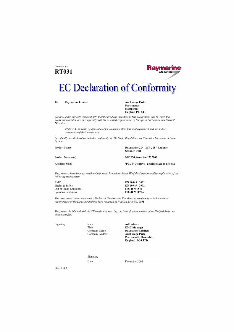
Sheet 1 of 2
Certificate No.
RT031
We Raymarine Limited Anchorage Park Portsmouth Hampshire England P03 5TD
declare, under our sole responsibility, that the products identified in this declaration, and to which this declaration relates, are in conformity with the essential requirements of European Parliament and Council Directive:
1999/5/EC on radio equipment and telecommunication terminal equipment and the mutual recognition of their conformity.
Specifically this declaration includes conformity to ITU Radio Regulations on Unwanted Emissions of Radar Systems. Product Name: Raymarine 2D – 2kW, 18" Radome Scanner Unit Product Number(s): M92650, from S/n 1222000 Ancillary Units 'PLUS' Displays - details given on Sheet 2 The products have been assessed to Conformity Procedure Annex IV of the Directive and by application of the following standard(s):
EMC EN 60945 : 2002 Health & Safety EN 60945 : 2002 Out of Band Emissions ITU-R M1541 Spurious Emissions ITU-R M1177-2 The assessment is consistent with a Technical Construction File showing conformity with the essential requirements of the Directive and has been reviewed by Notified Body No. 0191 The product is labelled with the CE conformity marking, the identification number of the Notified Body and class identifier. Signatory: Name Adil Abbas Title EMC Manager Company Name Raymarine Limited Company Address Anchorage Park Portsmouth, Hampshire England PO3 5TD
Signature _________________________
Date December 2002
Sheet 2 of 2
Certificate No.
RT031
Declaration of Conformity – Schedule of Ancillary Equipment and Radar Systems The following Raymarine Display Units are combined with the Raymarine 2D – 2kW, 18" Radome Scanner Unit (transceiver) listed on Sheet 1 to form the operational radar systems given below. Details of these units are included in the Technical Construction File:
DISPLAY (one of)
Description Designation Part No. Display Unit, 7" Mono LCD SL70 PLUS E52028 Display Unit, 7" Mono LCD/Chart SL70RC PLUS R58149 Display Unit, 7" Mono LCD SL70M PLUS E52043 Display Unit, 7" Mono LCD/Chart SL70MRC PLUS E52044 Display Unit, 7" Mono LCD/hsb² RL70 PLUS E52031 Display Unit, 7" Mono LCD/hsb²/Chart RL70RC PLUS E52032 Display Unit, 7" CRT/hsb² R70 PLUS E52039 Display Unit, 7" CRT/hsb²/Chart R70RC PLUS E52040 Display Unit, 10" CRT/hsb² R80 PLUS E52035 Display Unit, 10" CRT/hsb²/Chart R80RC PLUS E52036 Display Unit, 7" Colour LCD SL70C PLUS E52045/E52045HB Display Unit, 7" Colour LCD /Chart SL70CRC PLUS E52046/E52046HB Display Unit, 7" Colour LCD/hsb² RL70C PLUS E52033/E52033HB Display Unit, 7" Colour LCD hsb²/Chart RL70CRC PLUS E52034/E52034HB Display Unit, 10" Colour LCD/hsb² RL80C PLUS E52037 Display Unit, 10" Colour LCD/hsb²/Chart RL80CRC PLUS E52038
Note: 7" Colour LCD Units with "HB" suffix Part No's, have higher brightness displays.
PATHFINDER RADAR SYSTEMS
Designation Radar System Scanner Unit Display Unit SL72 PLUS 2D SL70 PLUS SL72RC PLUS 2D SL70RC PLUS SL72M PLUS 2D SL70M PLUS SL72MRC PLUS 2D SL70MRC PLUS RL72 PLUS 2D RL70 PLUS RL72RC PLUS 2D RL70RC PLUS R72 PLUS 2D R70 PLUS R72RC PLUS 2D R70RC PLUS R82 PLUS 2D R80 PLUS R82RC PLUS 2D R80RC PLUS SL72C PLUS 2D SL70C PLUS SL72CRC PLUS 2D SL70CRC PLUS RL72C PLUS 2D RL70C PLUS RL72CRC PLUS 2D RL70CRC PLUS RL82C PLUS 2D RL80C PLUS RL82CRC PLUS 2D RL80CRC PLUS
Sheet 1 of 2
Certificate No.
RT032
We Raymarine Limited Anchorage Park Portsmouth Hampshire England P03 5TD
declare, under our sole responsibility, that the products identified in this declaration, and to which this declaration relates, are in conformity with the essential requirements of European Parliament and Council Directive:
1999/5/EC on radio equipment and telecommunication terminal equipment and the mutual recognition of their conformity.
Specifically this declaration includes conformity to ITU Radio Regulations on Unwanted Emissions of Radar systems
Product Name: Raymarine 4D – 4kW, 24" Radome Scanner Unit Product Number(s): M92652, from S/n 1222000 Ancillary Units 'PLUS' Displays - details given on Sheet 2 The products have been assessed to Conformity Procedure Annex IV of the Directive and by application of the following standard(s):
EMC EN 60945 : 1997 Health & Safety EN 60945 : 1997 Out of Band Emissions ITU-R M1541 Spurious Emissions ITU-R M1177-2 The assessment is consistent with a Technical Construction File showing conformity with the essential requirements of the Directive and has been reviewed by Notified Body No. 0191 The product is labelled with the CE conformity marking, the identification number of the Notified Body and class identifier. Signatory: Name Adil Abbas Title EMC Manager Company Name Raymarine Limited Company Address Anchorage Park Portsmouth, Hampshire England PO3 5TD
Signature _________________________
Date December 2002
Sheet 2 of 2
Certificate No.
RT032
Declaration of Conformity – Schedule of Ancillary Equipment and Radar Systems The following Raymarine Display Units are combined with the Raymarine 4D – 4kW, 24" Radome Scanner Unit (transceiver) listed on Sheet 1 to form the operational radar systems given below. Details of these units are included in the Technical Construction File:
DISPLAY (one of)
Description Designation Part No. Display Unit, 7" Mono LCD SL70M PLUS E52043 Display Unit, 7" Mono LCD/Chart SL70MRC PLUS E52044 Display Unit, 7" Mono LCD/hsb² RL70 PLUS E52031 Display Unit, 7" Mono LCD/hsb²/Chart RL70RC PLUS E52032 Display Unit, 7" CRT/hsb² R70 PLUS E52039 Display Unit, 7" CRT/hsb²/Chart R70RC PLUS E52040 Display Unit, 10" CRT/hsb² R80 PLUS E52035 Display Unit, 10" CRT/hsb²/Chart R80RC PLUS E52036 Display Unit, 7" Colour LCD SL70C PLUS E52045/E52045HB Display Unit, 7" Colour LCD /Chart SL70CRC PLUS E52046/E52046HB Display Unit, 7" Colour LCD/hsb² RL70C PLUS E52033/E52033HB Display Unit, 7" Colour LCD hsb²/Chart RL70CRC PLUS E52034/E52034HB Display Unit, 10" Colour LCD/hsb² RL80C PLUS E52037 Display Unit, 10" Colour LCD/hsb²/Chart RL80CRC PLUS E52038
Note: Colour LCD Units with "HB" suffix Part No's, have higher brightness displays.
PATHFINDER RADAR SYSTEMS
Designation Radar System Scanner Unit Display Unit SL74M PLUS 4D SL70M PLUS SL74MRC PLUS 4D SL70MRC PLUS RL74 PLUS 4D RL70 PLUS RL74RC PLUS 4D RL70RC PLUS R74 PLUS 4D R70 PLUS R74RC PLUS 4D R70RC PLUS R84 PLUS 4D R80 PLUS R84RC PLUS 4D R80RC PLUS SL74C PLUS 4D SL70C PLUS SL74CRC PLUS 4D SL70CRC PLUS RL74C PLUS 4D RL70C PLUS RL74CRC PLUS 4D RL70CRC PLUS RL84C PLUS 4D RL80C PLUS RL84CRC PLUS 4D RL80CRC PLUS

Sheet 1 of 2
Certificate No.
RT033
We Raymarine Limited Anchorage Park Portsmouth Hampshire England P03 5TD
declare, under our sole responsibility, that the products identified in this declaration, and to which this declaration relates, are in conformity with the essential requirements of European Parliament and Council Directive:
1999/5/EC on radio equipment and telecommunication terminal equipment and the mutual recognition of their conformity.
Specifically this declaration includes conformity to ITU Radio Regulations on Unwanted Emissions of Radar Systems.
Product Name: Raymarine 4kW Open Array Scanner Unit Product Number(s): M92654 Ancillary Units Details are given on Sheet 2 The products have been assessed to Conformity Procedure Annex IV of the Directive and by application of the following standard(s):
EMC EN 60945 : 1997 Health & Safety EN 60945 : 1997 Out of Band Emissions ITU-R M1541 Spurious Emissions ITU-R M1177-2 The assessment is consistent with a Technical Construction File showing conformity with the essential requirements of the Directive and has been reviewed by Notified Body No. 0191 The product is labelled with the CE conformity marking, the identification number of the Notified Body and class identifier. Signatory: Name Adil Abbas Title EMC Manager Company Name Raymarine Limited Company Address Anchorage Park Portsmouth, Hampshire England PO3 5TD
Signature _________________________
Date 23rd December 2002
Sheet 2 of 2
Certificate No.
RT033 Declaration of Conformity – Schedule of Ancillary Equipment and Radar Systems The following units are combined with the 4kW, Open Array Scanner Unit (transceiver) listed on Sheet 1 to form the operational Raytheon or Raymarine radar systems given below. Details of these units are included in the Technical Construction File:
DISPLAY (one of)
Description Designation Part No. Display Unit, 7" Mono LCD SL70M PLUS E52043 Display Unit, 7" Mono LCD/Chart SL70MRC PLUS E52044 Display Unit, 7" Mono LCD/hsb² RL70 PLUS E52031 Display Unit, 7" Mono LCD/hsb²/Chart RL70RC PLUS E52032 Display Unit, 7" CRT/hsb² R70 PLUS E52039 Display Unit, 7" CRT/hsb²/Chart R70RC PLUS E52040 Display Unit, 10" CRT/hsb² R80 PLUS E52035 Display Unit, 10" CRT/hsb²/Chart R80RC PLUS E52036 Display Unit, 7" Colour LCD SL70C PLUS E52045/E52045HB Display Unit, 7" Colour LCD /Chart SL70CRC PLUS E52046/E52046HB Display Unit, 7" Colour LCD/hsb² RL70C PLUS E52033/E52033HB Display Unit, 7" Colour LCD hsb²/Chart RL70CRC PLUS E52034/E52034HB Display Unit, 10" Colour LCD/hsb² RL80C PLUS E52037 Display Unit, 10" Colour LCD/hsb²/Chart RL80CRC PLUS E52038
Note: 7" Colour LCD Units with "HB" suffix Part No's, have higher brightness displays.
ANTENNA (one of)
Description Scanner Unit Designation (Transceiver + Antenna)
Part No.
48" Antenna 5S M92693 72" Antenna 7S M92743
PATHFINDER RADAR SYSTEMS
Designation Radar System Scanner Display Unit SL75M PLUS 5S SL70M PLUS SL75MRC PLUS 5S SL70MRC PLUS RL75 PLUS 5S RL70 PLUS RL75RC PLUS 5S RL70RC PLUS R75 PLUS 5S R70 PLUS R75RC PLUS 5S R70RC PLUS R85 PLUS 5S R80 PLUS R85RC PLUS 5S R80RC PLUS SL75C PLUS 5S SL70C PLUS SL75CRC PLUS 5S SL75CRC PLUS RL75C PLUS 5S RL70C PLUS RL75CRC PLUS 5S RC70CRC PLUS RL85C PLUS 5S RL80C PLUS RL85CRC PLUS 5S RL80CRC PLUS
Designation Radar System Scanner Display Unit SL77M PLUS 7S SL70M PLUS SL77MRC PLUS 7S SL70MRC PLUS RL77 PLUS 7S RL70 PLUS RL77RC PLUS 7S RL70RC PLUS R77 PLUS 7S R70 PLUS R77RC PLUS 7S R70RC PLUS R87 PLUS 7S R80 PLUS R87RC PLUS 7S R80RC PLUS SL77C PLUS 7S SL70C PLUS SL77CRC PLUS 7S SL70CRC PLUS RL77C PLUS 7S RL70C PLUS RL77CRC PLUS 7S RC70CRC PLUS RL87C PLUS 7S RL80C PLUS RL87CRC PLUS 7S RL80CRC PLUS

Sheet 1 of 2
Certificate No.
RT035
We Raymarine Limited Anchorage Park Portsmouth Hampshire England P03 5TD
declare, under our sole responsibility, that the products identified in this declaration, and to which this declaration relates, are in conformity with the essential requirements of European Parliament and Council Directive:
1999/5/EC on radio equipment and telecommunication terminal equipment and the mutual recognition of their conformity.
Specifically this declaration includes conformity to ITU Radio Regulations on Unwanted Emissions of Radar Systems.
Product Name: Raymarine 10kW Open Array Scanner Unit Product Number(s): M92655 Ancillary Units Details are given on Sheet 2 The products have been assessed to Conformity Procedure Annex IV of the Directive and by application of the following standard(s):
EMC EN 60945 : 1997 Health & Safety EN 60945 : 1997 Out of Band Emissions ITU-R M1541 Spurious Emissions ITU-R M1177-2 The assessment is consistent with a Technical Construction File showing conformity with the essential requirements of the Directive and has been reviewed by Notified Body No. 0191 The product is labelled with the CE conformity marking, the identification number of the Notified Body and class identifier. Signatory: Name Adil Abbas Title EMC Manager Company Name Raymarine Limited Company Address Anchorage Park Portsmouth, Hampshire England PO3 5TD
Signature _________________________
Date February 2002
Sheet 2 of 2
Certificate No.
RT035 Declaration of Conformity – Schedule of Ancillary Equipment and Radar Systems The following units are combined with the 10kW, Open Array Scanner Unit (transceiver) listed on Sheet 1 to form the operational Raymarine radar systems given below. Details of these units are included in the Technical Construction File:
DISPLAY (one of)
Description Designation Part No. Display Unit, 7" Mono LCD SL70M PLUS E52043 Display Unit, 7" Mono LCD/Chart SL70MRC PLUS E52044 Display Unit, 7" Mono LCD/hsb² RL70 PLUS E52031 Display Unit, 7" Mono LCD/hsb²/Chart RL70RC PLUS E52032 Display Unit, 7" CRT/hsb² R70 PLUS E52039 Display Unit, 7" CRT/hsb²/Chart R70RC PLUS E52040 Display Unit, 10" CRT/hsb² R80 PLUS E52035 Display Unit, 10" CRT/hsb²/Chart R80RC PLUS E52036 Display Unit, 7" Colour LCD SL70C PLUS E52045/E52045HB Display Unit, 7" Colour LCD /Chart SL70CRC PLUS E52046/E52046HB Display Unit, 7" Colour LCD/hsb² RL70C PLUS E52033/E52033HB Display Unit, 7" Colour LCD hsb²/Chart RL70CRC PLUS E52034/E52034HB Display Unit, 10" Colour LCD/hsb² RL80C PLUS E52037 Display Unit, 10" Colour LCD/hsb²/Chart RL80CRC PLUS E52038
Note: 7" Colour LCD Units with "HB" suffix Part No's, have higher brightness displays.
ANTENNA (one of)
Description Scanner Unit Designation (Transceiver + Antenna)
Part No.
48" Antenna 5S M92693 72" Antenna 7S M92743
PATHFINDER RADAR SYSTEMS
Designation Radar System Scanner Display Unit SL79M PLUS 9S SL70M PLUS SL79MRC PLUS 9S SL70MRC PLUS RL79 PLUS 9S RL70 PLUS RL79RC PLUS 9S RL70RC PLUS R79 PLUS 9S R70 PLUS R79RC PLUS 9S R70RC PLUS R89 PLUS 9S R80 PLUS R89RC PLUS 9S R80RC PLUS SL79C PLUS 9S SL70C PLUS SL79CRC PLUS 9S SL75CRC PLUS RL79C PLUS 9S RL70C PLUS RL79CRC PLUS 9S RC70CRC PLUS RL89C PLUS 9S RL80C PLUS RL89CRC PLUS 9S RL80CRC PLUS
Designation Radar System Scanner Display Unit SL711M PLUS 11S SL70M PLUS SL711MRC PLUS 11S SL70MRC PLUS RL711 PLUS 11S RL70 PLUS RL711RC PLUS 11S RL70RC PLUS R711 PLUS 11S R70 PLUS R711RC PLUS 11S R70RC PLUS R811 PLUS 11S R80 PLUS R811RC PLUS 11S R80RC PLUS SL711C PLUS 11S SL70C PLUS SL711CRC PLUS 11S SL70CRC PLUS RL711C PLUS 11S RL70C PLUS RL711CRC PLUS 11S RC70CRC PLUS RL811C PLUS 11S RL80C PLUS RL811CRC PLUS 11S RL80CRC PLUS

Sheet 1 of 2
Certificate No.
RT038
We Raymarine Limited Anchorage Park Portsmouth Hampshire England P03 5TD
declare, under our sole responsibility, that the products identified in this declaration, and to which this declaration relates, are in conformity with the essential requirements of European Parliament and Council Directive:
1999/5/EC on radio equipment and telecommunication terminal equipment and the mutual recognition of their conformity.
Specifically this declaration includes conformity to ITU Radio Regulations on Unwanted Emissions of Radar Systems. Product Name: Raymarine 2D – 2kW, 18" Radome Scanner Unit Product Number(s): M92650, from S/n 1222000 Ancillary Units C-series Displays - details given on Sheet 2 The products have been assessed to Conformity Procedure Annex IV of the Directive and by application of the following standard(s):
EMC EN 60945 : 2002 Health & Safety EN 60945 : 2002 Out of Band Emissions ITU-R M1541 Spurious Emissions ITU-R M1177-2 The assessment is consistent with a Technical Construction File showing conformity with the essential requirements of the Directive and has been reviewed by Notified Body No. 0191 The product is labelled with the CE conformity marking, the identification number of the Notified Body and class identifier. Signatory: Name Adil Abbas Title International Compliance Manager Company Name Raymarine Limited Company Address Anchorage Park Portsmouth, Hampshire England PO3 5TD
Signature _________________________
Date 13 February 2004
Sheet 2 of 2
Certificate No.
RT038
Declaration of Conformity – Schedule of Ancillary Equipment * The following Raymarine Display Units are combined with the Raymarine 2D – 2kW, 18" Radome Scanner Unit (transceiver) listed on Sheet 1 to form the operational radar systems. Details of these units are included in the Technical Construction File:
DISPLAY (one of)
Description Designation Part No. Display Unit, 7" Colour LCD /Chart C70 E02018 Display Unit, 8" Colour LCD/Chart C80 E02020 Display Unit, 12" Colour LCD/Chart C120 E02022

Sheet 1 of 2
Certificate No.
RT039
We Raymarine Limited Anchorage Park Portsmouth Hampshire England P03 5TD
declare, under our sole responsibility, that the products identified in this declaration, and to which this declaration relates, are in conformity with the essential requirements of European Parliament and Council Directive:
1999/5/EC on radio equipment and telecommunication terminal equipment and the mutual recognition of their conformity.
Specifically this declaration includes conformity to ITU Radio Regulations on Unwanted Emissions of Radar Systems. Product Name: Raymarine 4D – 4kW, 24" Radome Scanner Unit Product Number(s): M92652, from S/n 1222000 Ancillary Units C-series Displays - details given on Sheet 2 The products have been assessed to Conformity Procedure Annex IV of the Directive and by application of the following standard(s):
EMC EN 60945 : 2002 Health & Safety EN 60945 : 2002 Out of Band Emissions ITU-R M1541 Spurious Emissions ITU-R M1177-2 The assessment is consistent with a Technical Construction File showing conformity with the essential requirements of the Directive and has been reviewed by Notified Body No. 0191 The product is labelled with the CE conformity marking, the identification number of the Notified Body and class identifier. Signatory: Name Adil Abbas Title International Compliance Manager Company Name Raymarine Limited Company Address Anchorage Park Portsmouth, Hampshire England PO3 5TD
Signature _________________________
Date 13 February 2004

Sheet 2 of 2
Certificate No.
RT039
Declaration of Conformity – Schedule of Ancillary Equipment The following Raymarine Display Units are combined with the Raymarine 4D – 4kW, 24" Radome Scanner Unit (transceiver) listed on Sheet 1 to form the operational radar systems. Details of these units are included in the Technical Construction File:
DISPLAY (one of)
Description Designation Part No. Display Unit, 7" Colour LCD /Chart C70 E02018 Display Unit, 8" Colour LCD/Chart C80 E02020 Display Unit, 12" Colour LCD/Chart C120 E02022

Sheet 1 of 2
Certificate No.
RT040
We Raymarine Limited Anchorage Park Portsmouth Hampshire England P03 5TD
declare, under our sole responsibility, that the products identified in this declaration, and to which this declaration relates, are in conformity with the essential requirements of European Parliament and Council Directive:
1999/5/EC on radio equipment and telecommunication terminal equipment and the mutual recognition of their conformity.
Specifically this declaration includes conformity to ITU Radio Regulations on Unwanted Emissions of Radar Systems. Product Name: Raymarine 4kW Open Array Scanner Unit Product Number(s): M92654, from S/n 0132000 Ancillary Units C-series Displays - details given on Sheet 2 The products have been assessed to Conformity Procedure Annex IV of the Directive and by application of the following standard(s):
EMC EN 60945 : 2002 Health & Safety EN 60945 : 2002 Out of Band Emissions ITU-R M1541 Spurious Emissions ITU-R M1177-2 The assessment is consistent with a Technical Construction File showing conformity with the essential requirements of the Directive and has been reviewed by Notified Body No. 0191 The product is labelled with the CE conformity marking, the identification number of the Notified Body and class identifier. Signatory: Name Adil Abbas Title International Compliance Manager Company Name Raymarine Limited Company Address Anchorage Park Portsmouth, Hampshire England PO3 5TD
Signature _________________________
Date 13 February 2004
Sheet 2 of 2
Certificate No.
RT040
Declaration of Conformity – Schedule of Ancillary Equipment The following Raymarine Display Units are combined with the Raymarine 4kW, Open Array Scanner Unit (transceiver) listed on Sheet 1 to form the operational radar systems. Details of these units are included in the Technical Construction File:
DISPLAY (one of)
Description Designation Part No. Display Unit, 7" Colour LCD /Chart C70 E02018 Display Unit, 8" Colour LCD/Chart C80 E02020 Display Unit, 12" Colour LCD/Chart C120 E02022
ANTENNA (one of)
Description Scanner Unit Designation (Transceiver + Antenna) Part No.
48" Antenna Array 5S M92693 72" Antenna Array 7S M92743
Sheet 1 of 2
Certificate No.
RT041
We Raymarine Limited Anchorage Park Portsmouth Hampshire England P03 5TD
declare, under our sole responsibility, that the products identified in this declaration, and to which this declaration relates, are in conformity with the essential requirements of European Parliament and Council Directive:
1999/5/EC on radio equipment and telecommunication terminal equipment and the mutual recognition of their conformity.
Specifically this declaration includes conformity to ITU Radio Regulations on Unwanted Emissions of Radar Systems. Product Name: Raymarine 10kW Open Array Scanner Unit Product Number(s): M92655, from S/n 0332000 Ancillary Units C-series Displays - details given on Sheet 2 The products have been assessed to Conformity Procedure Annex IV of the Directive and by application of the following standard(s):
EMC EN 60945 : 2002 Health & Safety EN 60945 : 2002 Out of Band Emissions ITU-R M1541 Spurious Emissions ITU-R M1177-2 The assessment is consistent with a Technical Construction File showing conformity with the essential requirements of the Directive and has been reviewed by Notified Body No. 0191 The product is labelled with the CE conformity marking, the identification number of the Notified Body and class identifier. Signatory: Name Adil Abbas Title International Compliance Manager Company Name Raymarine Limited Company Address Anchorage Park Portsmouth, Hampshire England PO3 5TD
Signature _________________________
Date 13 February 2004
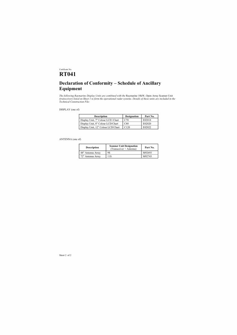
Sheet 2 of 2
Certificate No.
RT041
Declaration of Conformity – Schedule of Ancillary Equipment The following Raymarine Display Units are combined with the Raymarine 10kW, Open Array Scanner Unit (transceiver) listed on Sheet 1 to form the operational radar systems. Details of these units are included in the Technical Construction File:
DISPLAY (one of)
Description Designation Part No. Display Unit, 7" Colour LCD /Chart C70 E02018 Display Unit, 8" Colour LCD/Chart C80 E02020 Display Unit, 12" Colour LCD/Chart C120 E02022
ANTENNA (one of)
Description Scanner Unit Designation (Transceiver + Antenna) Part No.
48" Antenna Array 9S M92693 72" Antenna Array 11S M92743
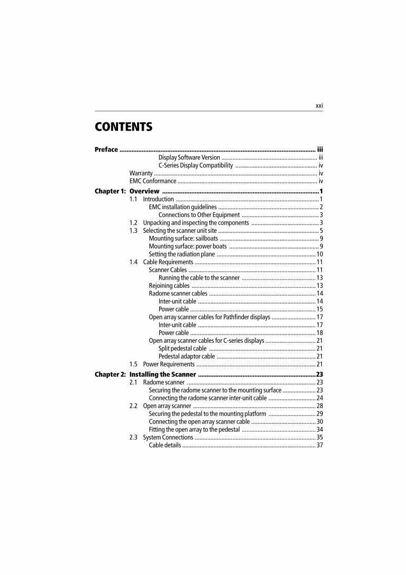
xxi
CONTENTS
Preface ................................................................................................................... iiiDisplay Software Version ............................................................. iiiC-Series Display Compatibility .................................................... iv
Warranty ........................................................................................................ ivEMC Conformance ......................................................................................... iv
Chapter 1: Overview ............................................................................................11.1 Introduction ........................................................................................... 1
EMC installation guidelines ................................................................ 2Connections to Other Equipment ................................................. 3
1.2 Unpacking and inspecting the components ........................................... 31.3 Selecting the scanner unit site ................................................................ 5
Mounting surface: sailboats ............................................................... 9Mounting surface: power boats ......................................................... 9Setting the radiation plane ............................................................... 10
1.4 Cable Requirements ............................................................................. 11Scanner Cables ................................................................................. 11
Running the cable to the scanner ............................................... 13Rejoining cables ............................................................................... 13Radome scanner cables .................................................................... 14
Inter-unit cable ........................................................................... 14Power cable ................................................................................ 15
Open array scanner cables for Pathfinder displays ............................ 17Inter-unit cable ........................................................................... 17Power cable ................................................................................ 18
Open array scanner cables for C-series displays ................................ 21Split pedestal cable .................................................................... 21Pedestal adaptor cable ............................................................... 21
1.5 Power Requirements ............................................................................ 21
Chapter 2: Installing the Scanner .....................................................................232.1 Radome scanner .................................................................................. 23
Securing the radome scanner to the mounting surface ..................... 23Connecting the radome scanner inter-unit cable .............................. 24
2.2 Open array scanner .............................................................................. 28Securing the pedestal to the mounting platform .............................. 29Connecting the open array scanner cable ......................................... 30Fitting the open array to the pedestal ............................................... 34
2.3 System Connections ............................................................................. 35Cable details ..................................................................................... 37
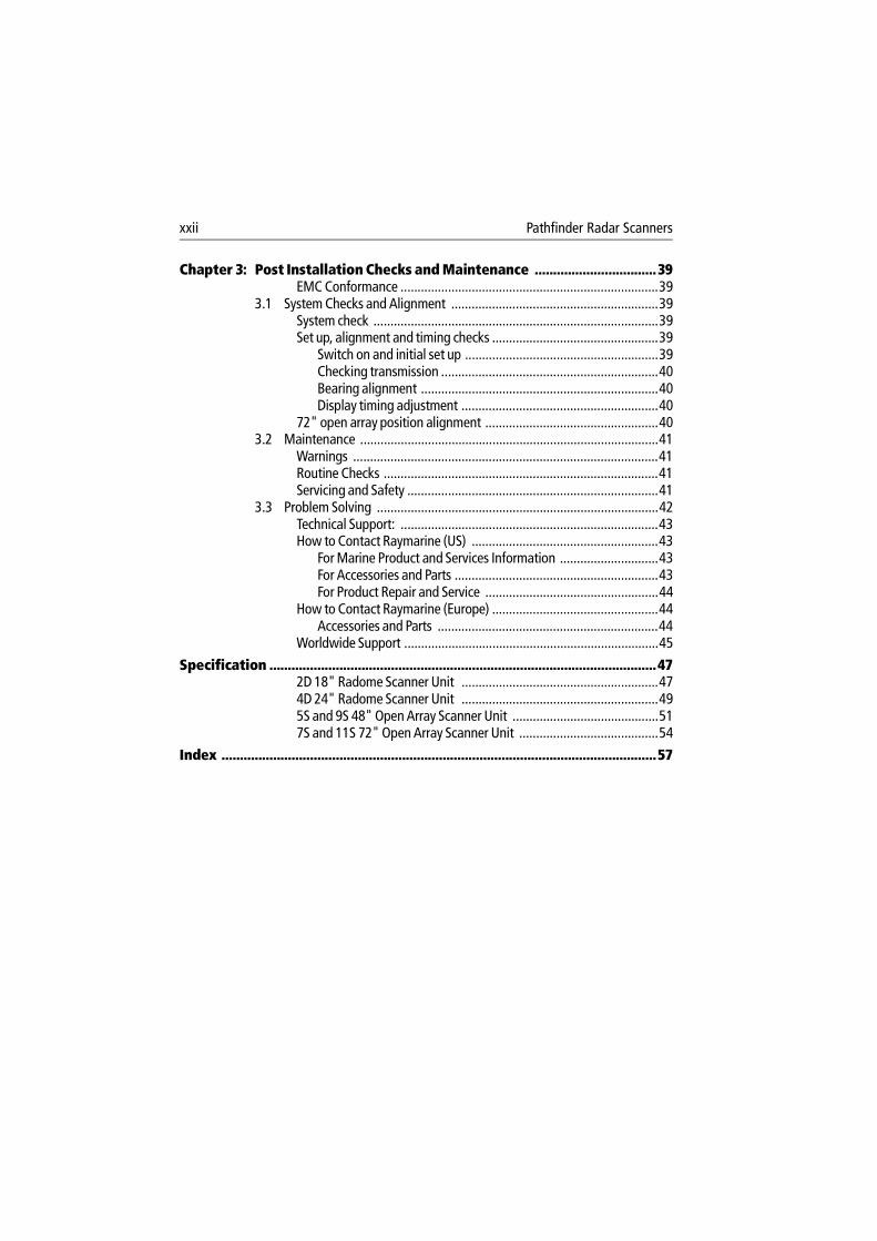
xxii Pathfinder Radar Scanners
Chapter 3: Post Installation Checks and Maintenance .................................39EMC Conformance ............................................................................39
3.1 System Checks and Alignment .............................................................39System check ....................................................................................39Set up, alignment and timing checks .................................................39
Switch on and initial set up .........................................................39Checking transmission ................................................................40Bearing alignment ......................................................................40Display timing adjustment ..........................................................40
72" open array position alignment ...................................................403.2 Maintenance ........................................................................................41
Warnings ..........................................................................................41Routine Checks .................................................................................41Servicing and Safety ..........................................................................41
3.3 Problem Solving ...................................................................................42Technical Support: ............................................................................43How to Contact Raymarine (US) .......................................................43
For Marine Product and Services Information .............................43For Accessories and Parts ............................................................43For Product Repair and Service ...................................................44
How to Contact Raymarine (Europe) .................................................44Accessories and Parts .................................................................44
Worldwide Support ...........................................................................45
Specification .........................................................................................................472D 18" Radome Scanner Unit ..........................................................474D 24" Radome Scanner Unit ..........................................................495S and 9S 48" Open Array Scanner Unit ...........................................517S and 11S 72" Open Array Scanner Unit .........................................54
Index ......................................................................................................................57

xxiii

xxiv Pathfinder Radar Scanners
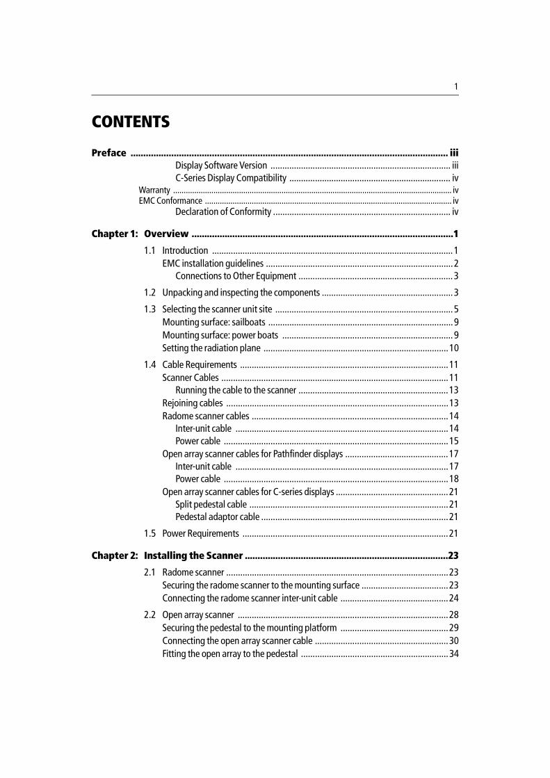
1
CONTENTS
Preface ............................................................................................................................. iiiDisplay Software Version ............................................................................. iiiC-Series Display Compatibility ..................................................................... iv
Warranty ................................................................................................................................... ivEMC Conformance .................................................................................................................... iv
Declaration of Conformity ............................................................................ iv
Chapter 1: Overview .......................................................................................................1
1.1 Introduction .......................................................................................................1EMC installation guidelines ................................................................................2
Connections to Other Equipment ..................................................................3
1.2 Unpacking and inspecting the components ........................................................3
1.3 Selecting the scanner unit site ............................................................................5Mounting surface: sailboats ...............................................................................9Mounting surface: power boats .........................................................................9Setting the radiation plane ...............................................................................10
1.4 Cable Requirements .........................................................................................11Scanner Cables .................................................................................................11
Running the cable to the scanner ................................................................13Rejoining cables ...............................................................................................13Radome scanner cables ....................................................................................14
Inter-unit cable ...........................................................................................14Power cable ................................................................................................15
Open array scanner cables for Pathfinder displays ............................................17Inter-unit cable ...........................................................................................17Power cable ................................................................................................18
Open array scanner cables for C-series displays ................................................21Split pedestal cable .....................................................................................21Pedestal adaptor cable ................................................................................21
1.5 Power Requirements ........................................................................................21
Chapter 2: Installing the Scanner ................................................................................23
2.1 Radome scanner ...............................................................................................23Securing the radome scanner to the mounting surface .....................................23Connecting the radome scanner inter-unit cable ..............................................24
2.2 Open array scanner ..........................................................................................28Securing the pedestal to the mounting platform ..............................................29Connecting the open array scanner cable .........................................................30Fitting the open array to the pedestal ...............................................................34
2 Pathfinder Radar Scanners
2.3 System Connections .........................................................................................35Cable details .....................................................................................................37
Chapter 3: Post Installation Checks and Maintenance ............................................39EMC Conformance ...........................................................................................39
3.1 System Checks and Alignment .........................................................................39System check ....................................................................................................39Set up, alignment and timing checks ................................................................39
Switch on and initial set up .........................................................................39Checking transmission ................................................................................40Bearing alignment ......................................................................................40Display timing adjustment ..........................................................................40
72" open array position alignment ...................................................................40
3.2 Maintenance ....................................................................................................41Warnings ..........................................................................................................41Routine Checks .................................................................................................41Servicing and Safety .........................................................................................41
3.3 Problem Solving ...............................................................................................42Technical Support: ............................................................................................43How to Contact Raymarine (US) .......................................................................43
For Marine Product and Services Information .............................................43For Accessories and Parts ............................................................................43For Product Repair and Service ....................................................................44
How to Contact Raymarine (Europe) ................................................................44Accessories and Parts ..................................................................................44
Worldwide Support ..........................................................................................45
Specification ..................................................................................................................................472D 18" Radome Scanner Unit ..........................................................................474D 24" Radome Scanner Unit ..........................................................................495S and 9S 48" Open Array Scanner Unit ..........................................................517S and 11S 72" Open Array Scanner Unit ........................................................54
1
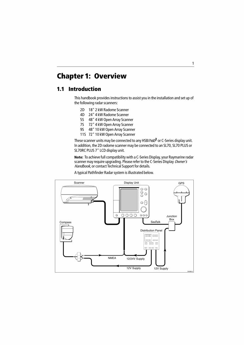
Chapter 1: Overview
1.1 IntroductionThis handbook provides instructions to assist you in the installation and set up of the following radar scanners:
2D 18" 2 kW Radome Scanner4D 24" 4 kW Radome Scanner5S 48" 4 kW Open Array Scanner7S 72" 4 kW Open Array Scanner9S 48" 10 kW Open Array Scanner11S 72" 10 kW Open Array Scanner
These scanner units may be connected to any HSB/hsb2 or C-Series display unit. In addition, the 2D radome scanner may be connected to an SL70, SL70 PLUS or SL70RC PLUS 7" LCD display unit.
Note: To achieve full compatibility with a C-Series Display, your Raymarine radar scanner may require upgrading. Please refer to the C-Series Display Owner’s Handbook, or contact Technical Support for details.
A typical Pathfinder Radar system is illustrated below.
NMEA
SeaTalk
Display Unit
Distribution Panel
D4288-4
Scanner
12/24V Supply
12V Supply 12V Supply
JunctionBox
GPS
Compass
2 Pathfinder Radar Scanners
CAUTION: Do not use an open array scanner with an SL70, SL70 PLUS or SL70RC PLUS 7" LCD display unit. Failure to observe this may result in permanent damage to these display units.The 10 kW open array scanner requires 24 V or higher; it will not operate on 12 V systems.
This handbook is divided into three chapters as follows:
Chapter One provides information to help you plan the scanner installation. It includes sections on Unpacking and Inspecting the Components, Selecting the Scanner Site, Cable Requirements and Power Requirements.
Chapter Two provides detailed instructions on how to mount and connect each type of scanner.
Chapter Three provides instructions on how to perform the system checks, alignment and adjustments. It also provides information on maintenance and what to do if you have problems.
EMC installation guidelinesAll Raymarine equipment and accessories are designed to the best industry standards for use in the leisure marine environment.
Their design and manufacture conforms to the appropriate Electromagnetic Compatibility (EMC) standards, but correct installation is required to ensure that performance is not compromised. Although every effort has been taken to ensure that they will perform under all conditions, it is important to understand what factors could affect the operation of the product.
The guidelines given here describe the conditions for optimum EMC performance, but it is recognized that it may not be possible to meet all of these conditions in all situations. To ensure the best possible conditions for EMC performance within the constraints imposed by any location, always ensure the maximum separation possible between different items of electrical equipment.
For optimum EMC performance, it is recommended that wherever possible:
• Raymarine equipment and cables connected to it are:• At least 1 m (3 ft) from any equipment transmitting or cables carrying
radio signals e.g. VHF radios, cables and antennas. In the case of SSB radios, the distance should be increased to 2 m (7 ft).
• More than 2 m (7 ft) from the path of a radar beam. A radar beam can nor-mally be assumed to spread 20 degrees above and below the radiating element.
3
• The equipment is supplied from a separate battery from that used for engine start. Voltage drops below 10 V (20 V for 10 kW open array scanners) in the power supply to our products, and starter motor transients, can cause the equipment to reset. This will not damage the equipment, but may cause the loss of some information and may change the operating mode.
• Raymarine specified cables are used at all times. Cutting and rejoining these cables can compromise EMC performance and so must be avoided unless doing so is detailed in the installation manual.
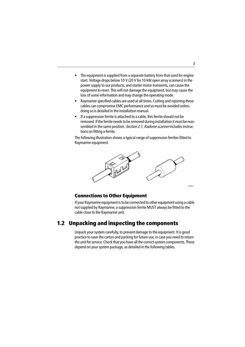
• If a suppression ferrite is attached to a cable, this ferrite should not be removed. If the ferrite needs to be removed during installation it must be reas-sembled in the same position. Section 2.1, Radome scanner includes instruc-tions on fitting a ferrite.
The following illustration shows a typical range of suppression ferrites fitted to Raymarine equipment.
Connections to Other EquipmentIf your Raymarine equipment is to be connected to other equipment using a cable not supplied by Raymarine, a suppression ferrite MUST always be fitted to the cable close to the Raymarine unit.
1.2 Unpacking and inspecting the componentsUnpack your system carefully, to prevent damage to the equipment. It is good practice to save the carton and packing for future use, in case you need to return the unit for service. Check that you have all the correct system components. These depend on your system package, as detailed in the following tables.
D3548-4
4 Pathfinder Radar Scanners
Table 1-1: Radome scanners
Item Part No.Supplied with: Option for:
2D 18" 2 kW Radome Scanner with15 m light cable
4D 24" 4 kW Radome Scanner with15 m heavy cable
M92650-S
M92652-S
-
-
-
-
Inter-unit cable 15 m heavyInter-unit cable 25 m heavyInter-unit cable 15 m lightInter-unit cable 10 m light
M92668M92669M92720M92692
4D-2D -
-Both-2D
Extension cable 5 mExtension cable 10 m
M92699M92700
--
BothBoth
Mast Mount 18" ScannerMast Mount 24" Scanner
M92722M92698
--
2D4D
Radome mounting interface plate M92731 - 2D
Table 1-2: Open array scanners
Item Part No.Supplied with: Option for:
4 kW Scanner Pedestal10 kW Scanner Pedestal48" Open Array72" Open Array
M92654-SM92655-SM92693M92743
5S, 7S9S, 11S 5S, 9S7S, 11S
----
Pathfinder CablesInter-unit cable 15 m heavyInter-unit cable 25 m heavyCable kit: 5 m +10 m extension(To fit open array scanner on a radar arch)Extension cable 5mExtension cable 10m
M92728M92705E55017
M92699M92700
---
--
5S,7S, 9S, 11S5S, 7S, 9S, 11S 5S, 7S, 9S,11S
5S, 7S, 9S, 11S5S, 7S, 9S, 11S
Note: 9S and 11S scanners require 24/32V
C-Series CablesSplit pedestal cable 25mSplit pedestal cable 15mPedestal adaptor cable
E05017E05018E05019
---
5S, 7S, 9S, 11S5S, 7S, 9S, 11S5S, 7S, 9S, 11S
Software Upgrade Kit Please contact your authorized dealer ordistributor for details

5
1.3 Selecting the scanner unit siteThis section provides information that affects the possible locations of the scanner, and its position relative to the display unit and to the power supply.
The dimensions of the each scanner unit are shown in the following diagrams.
Selecting the best location for the scanner unit requires careful consideration of the following points, to ensure reliable and trouble free operation:
Note: In order to minimize potential interference to other systems on board ship (EMC), it is advisable to mount the scanner on a part of the boat that is insulated from the ship’s bat-tery negative. If you cannot do this, and encounter problems, you can fit insulating bushes between the scanner and its mounting bracket.
• Height: The scanner unit should normally be mounted as high as practical above the waterline, for three reasons:• For safety reasons the scanner should be out of range of personnel, pref-
erably above head height. This avoids mechanical danger and electro-magnetic contact, particularly with the eyes.
• Radar operates at the line-of-sight, so a high mounting position gives bet-ter long range performance.
• Surrounding large objects, in the same horizontal plane, can interfere with the radar signal and cause blind areas or shadow sectors and false targets on the radar screen (see below).
However, do not mount the scanner so high that it is affected by the pitching and rolling of the vessel. In addition, you may need to lower the scanner to avoid creating a shadow sector underneath the scanner’s beam.
6 Pathfinder Radar Scanners
D3224_418" Radome Scanner
151.25 mm (5.95 in)468 mm (18.4 in) dia.
Weight: 6.5 kg (14.3 lbs)
Compass safe distance: 1 m (33 in)
116.
5 m
m(4
.6 in
)
233
mm
(9.2
in)
141.5 mm (5.6 in)
227
mm
(8.9
in)
302.5 mm (11.9 in)
Rear
Rear
D3228_5
Weight: 7.5 kg (16.5lbs)
Compass Safe Distance: 1m (33")
24" Radome Scanner
Rear
Rear
185.15 mm (7.3 in)
141.5 mm (5.6 in)
402 mm (15.8 in)
227
mm
(8.9
in)
233
mm
(9.2
in)
116.
5 m
m(4
.6 in
)
599 mm (23.6 in) dia.
7
Centre of rotation Centre of rotation
48"- 1306 mm (51.4 in), 72"- 1928 mm (75.9 in)
100 mm (4 in)
427 mm (16.8 in) 296 mm (11.65 in)
406
mm
(16
in)
D4572-4
WeightPedestal: 24 kg (53.0 lb)48" Open Array: 6 kg (13.2 lb)72" Open Array: 9.4 kg (20.7 lb)
Open Array Scanners
140
mm
(5.5
in)
Min
imum
cle
aran
ce h
eigh
t 510
mm
(20.
1 in
)
150 mm (6 in)
Minimum clearance 630 mm (24.8 in)
70 m
m
(2.7
5 in
)
Compass Safe Distance: 1 m (33 in)
8 Pathfinder Radar Scanners
• Access: The scanner unit site should be easily accessible to allow mainte-nance to be carried out safely.
• Magnetic compass: Mount the scanner unit at least 1 m away from a mag-netic compass.
• Cable run: The maximum length of cable between the display unit and the scanner unit should not normally exceed 20 m (60 ft) for radome scanners, or 15 m (45 ft) for open array scanners. If you need to use a longer cable power cable lengths must be considered, refer to Section 1.4 Cable Runs to deter-mine appropriate lengths.
• Shadow sectors and false echoes: Mount the scanner away from large structures or equipment, such as the fly bridge, large engine stacks, search-lights, horns, or masts. It is particularly important to avoid shadow sectors near the bow. Raising or even lowering the scanner may help to reduce these effects.In shadow areas beyond the obstruction there will be a reduction of the beam intensity, although not necessarily a complete cut-off; there will be a blind sector if the subtended angle is more than a few degrees.In some shadow sectors the beam intensity may not be sufficient to obtain an echo from a very small object, even at close range, despite the fact that a large vessel can be detected at a much greater range. For this reason the angular width and relative bearing of any shadow sector must be determined at installation. Sometimes shadowing can be seen by increasing the radar gain until noise is present. Dark sectors indicate possible shadowed areas. This information should be posted near the display unit and operators must be alert for targets in these blind sectors.It should also be noted that wet sails create shadow areas and thus sail boat operators should be aware that radar performance may reduce in rain.If you mount the scanner on a mast, echoes from the mast may appear on the radar display. These can be minimized by placing absorbing material, such as a block of wood, between the scanner and mast.
• Platform rigidity/stability: The scanner platform should not twist (caus-ing bearing errors) or be subject to excessive vibration.
• Heat/fumes: Mount the scanner away from the top of exhaust stacks, since the scanner and cables can be damaged by excessive heat and the corrosive effects of exhaust gases.
For open array scanners you should also consider the following points:
9
• Mounting Platform: The platform must be mechanically secure and capa-ble of supporting the mass and inertia of the open array scanner. The com-plete unit weighs: 48" scanner - 30 kg (66.2 lb); 72" scanner - 33.4 kg (73.7 lb).
• The site must be clear of ropes and moving rigging.• Sufficient clearance must be allowed to fully open the open array pedestal for
maintenance.
Mounting surface: sailboatsThe scanner unit can be installed on a mast platform, an arch, or a bridge structure. Make sure that the platform surface is flat and the scanner unit drain hole (radome scanners) is not obstructed. Raymarine recommends that radome scanner units are best suited for sailboat operation as open array systems are more difficult to protect from ropes and sails.
For sailboat installations, Raymarine offers a universal mast mount kit for each radome scanner type. This optional mount is used to fit a radome scanner to a flat surface on a mast with a minimum diameter of 60 mm (2½ in). When using the mast mount kit, appropriate hardware should be used for the style and structure of the mast aboard the vessel. Typically, the scanner will be mounted near the first set of mast spreaders. If there is any doubt concerning the appropriate type of hardware, consult your boat dealer or representative for their recommendations.
Depending on the type of sailboat, a radar scanner guard should be installed if the sails could touch the scanner or platform. Without a proper radar guard the mounting platform and the radar scanner could be severely damaged.
Mounting surface: power boatsOn many small vessels the scanner unit can be installed on a mast platform, an arch, or a bridge structure, but take care to follow the scanner site guidelines, particularly regarding height. If necessary, construct a radar mounting platform to obtain a sufficiently high mounting position. Make sure that the platform surface is flat and the scanner unit drain hole (radome scanners) is not obstructed. Ensure the platform is strong enough to support the maximum shock loads likely to occur.
10 Pathfinder Radar Scanners
Setting the radiation planeThe scanner unit should be mounted so that the array rotates parallel to the waterline. The radar beam is approximately 25° wide in the vertical direction, providing good target detection during the vessel’s pitching and rolling.
Planing hull vessels, and some displacement hull vessels, adopt a higher bow angle when the vessel is at its cruising speed. In many cases this substantially alters and raises the radar’s main radiation plane, and can cause poor detection of nearby targets. It may be helpful to lower the radar beam back towards the parallel, by shimming the rear of the radar, so that the beam points slightly downwards with respect to the waterline when the vessel is at rest.
The shims may be made from aluminium plate wedges, simple flat washers, or an angled wooden block. For thick shims, you may need longer securing bolts than the M8x40 bolts supplied with the radome scanner, or the M10 studding supplied with the open array scanners.
12.5˚
12.5˚
Waterline
Ideal Radiation Plane D3223-2
Wedge orwashers
Using shims to lower the main beam
D3229-3
Forward
11
1.4 Cable RequirementsThis section provides details on selecting the appropriate cables for your system. Permissible cable lengths depend on the scanner type and the boat’s power system. Information on inter-unit and power cables is provided for both radome and open array scanners in the following sections.
You need to consider the following before installing the cables:
• You need to connect the scanner to the display unit and to power. The cable required depends on the display unit and the scanner type as described below.
• All cables should be adequately clamped and protected from physical dam-age and exposure to heat - avoid running cables through bilges or doorways, or close to moving or hot objects.
• Acute bends must be avoided.• Where a cable passes through an exposed bulkhead or deckhead, a water-
tight gland or swan neck tube should be used.• Avoid cutting and re-joining cables (if necessary, refer to the notes below).
Scanner CablesThe cable used to connect your scanner to the display unit and power depends on the type of scanner and display as follows:
• A radome scanner connected to a Pathfinder or C-Series display requires an inter-unit cable. The scanner receives power via the display unit, the power cable is supplied with the display unit but cable details are provided in this section.
• An open array scanner connected to a Pathfinder display requires an inter-unit cable. The scanner receives power via the display unit, the power cable is sup-plied with the display unit but cable details are provided in this section.
• An open array scanner cannot be powered from a C-Series Display; it requires a split pedestal cable which combines the inter-unit and power cores.
• If you are connecting a C-series display to an existing open array scanner unit with a standard inter-unit cable, you can use the adapator cable instead of the split pedestal cable; connect the adaptor between the inter-unit cable and the display.
These cables are illustrated in the following diagram. Cable lengths and part numbers are listed in Unpacking and inspecting the components on page 3.
CAUTION: The cable for connecting an open array scanner to a C-series display cannot be extended.
12 Pathfinder Radar Scanners
Radome inter-unit cable for use with Pathfinder and C Series displays
Open array inter-unit cable for use with Pathfinder displays
Split pedestal cable for use with new open array scanner and C-Series display
Adaptor cable for use with existing open array scanner and C Series display
To display or extension(power supplied via display unit)
To display or extension(power supplied via display unit)
To display
To power
To display
To power
D6882-1
To existing scanner
To Radome Scanner
To Open Array Scanner
To Open Array Scanner
13
Running the cable to the scannerCAUTION: Do not pull the cable through bulkheads using a cord attached to the connector. This could damage the connections.
The cable entrance is at the rear of the scanner unit. If the unit is mounted on a hollow mast the cable may be run inside the mast and then fed through the radar’s cable entrance. Make sure that the cable does not chafe where it enters and exits the mast.
Note: Route the cable from the display up to the scanner, since this will require the smallest clearance hole.
Rejoining cablesYou should avoid cutting and re-joining cables. If this is necessary you must:
• Fit a ferrite on each side of the join. The specific ferrite to use depends on the cable type - contact Raymarine for details.
• Take care not to damage any of the wires. Make sure that all the wires and, in particular, the screen are reconnected correctly.
If you are mounting the scanner on the mast of a sailboat, and will need to unstep the mast, you should install a suitable junction box inside the boat.
On a radome scanner, the junction box should provide an 11- or 13-way terminal strip, depending on the number of power cores in your cable with a 10 A rating. Also, you should keep the length of the un-screened coaxial cores to less than 30 mm to maintain EMC conformance.
On an open array scanner, the junction box should provide a 13-way terminal strip with a 20 A rating for power cores. It is essential that all 4 power cores are connected and that the connection is of very low resistance as considerable power passes through this connection. Also, you should keep the length of the un-screened coaxial cores to less than 30 mm to maintain EMC conformance.
CAUTION: The display connector on the scanner cable is a moulded plug that cannot be replaced. DO NOT remove this moulded plug.
The minimum bends permitted are:
Minimum bend, light cable 60 mm (~2.5 in) radiusMinimum bend, heavy cable 82 mm (~3.75 in) radius
14 Pathfinder Radar Scanners
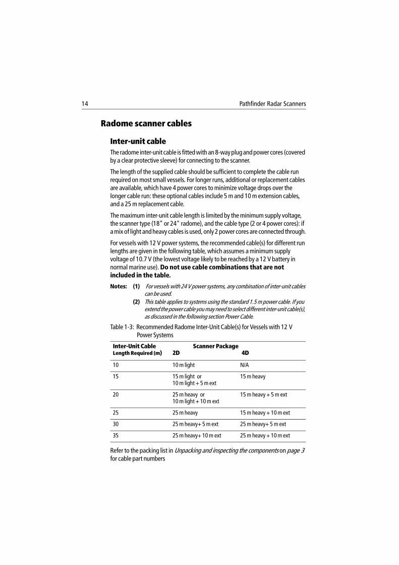
Radome scanner cables
Inter-unit cableThe radome inter-unit cable is fitted with an 8-way plug and power cores (covered by a clear protective sleeve) for connecting to the scanner.
The length of the supplied cable should be sufficient to complete the cable run required on most small vessels. For longer runs, additional or replacement cables are available, which have 4 power cores to minimize voltage drops over the longer cable run: these optional cables include 5 m and 10 m extension cables, and a 25 m replacement cable.
The maximum inter-unit cable length is limited by the minimum supply voltage, the scanner type (18" or 24" radome), and the cable type (2 or 4 power cores): if a mix of light and heavy cables is used, only 2 power cores are connected through.
For vessels with 12 V power systems, the recommended cable(s) for different run lengths are given in the following table, which assumes a minimum supply voltage of 10.7 V (the lowest voltage likely to be reached by a 12 V battery in normal marine use). Do not use cable combinations that are not included in the table.
Notes: (1) For vessels with 24 V power systems, any combination of inter-unit cables can be used.
(2) This table applies to systems using the standard 1.5 m power cable. If you extend the power cable you may need to select different inter-unit cable(s), as discussed in the following section Power Cable.
Refer to the packing list in Unpacking and inspecting the components on page 3 for cable part numbers
Table 1-3: Recommended Radome Inter-Unit Cable(s) for Vessels with 12 V Power Systems
Inter-Unit CableLength Required (m)
Scanner Package2D 4D
10 10 m light N/A
15 15 m light or10 m light + 5 m ext
15 m heavy
20 25 m heavy or 10 m light + 10 m ext
15 m heavy + 5 m ext
25 25 m heavy 15 m heavy + 10 m ext
30 25 m heavy+ 5 m ext 25 m heavy+ 5 m ext
35 25 m heavy+ 10 m ext 25 m heavy + 10 m ext
15
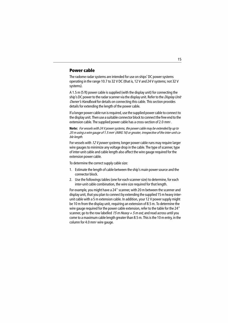
Power cableThe radome radar systems are intended for use on ships’ DC power systems operating in the range 10.7 to 32 V DC (that is, 12 V and 24 V systems; not 32 V systems).
A 1.5 m (5 ft) power cable is supplied (with the display unit) for connecting the ship’s DC power to the radar scanner via the display unit. Refer to the Display Unit Owner’s Handbook for details on connecting this cable. This section provides details for extending the length of the power cable.
If a longer power cable run is required, use the supplied power cable to connect to the display unit. Then use a suitable connector block to connect the free end to the extension cable. The supplied power cable has a cross-section of 2.0 mm2.
Note: For vessels with 24 V power systems, the power cable may be extended by up to 20 m using a wire gauge of 1.5 mm2 (AWG 16) or greater, irrespective of the inter-unit ca-ble length.
For vessels with 12 V power systems, longer power cable runs may require larger wire gauges to minimize any voltage drop in the cable. The type of scanner, type of inter-unit cable and cable length also affect the wire gauge required for the extension power cable.
To determine the correct supply cable size:
1. Estimate the length of cable between the ship’s main power source and the connector block.
2. Use the followings tables (one for each scanner size) to determine, for each inter-unit cable combination, the wire size required for that length.
For example, you might have a 24" scanner, with 20 m between the scanner and display unit, that you plan to connect by extending the supplied 15 m heavy inter-unit cable with a 5 m extension cable. In addition, your 12 V power supply might be 10 m from the display unit, requiring an extension of 8.5 m. To determine the wire gauge required for the power cable extension, refer to the table for the 24" scanner, go to the row labelled 15 m Heavy + 5 m ext, and read across until you come to a maximum cable length greater than 8.5 m. This is the 10 m entry, in the column for 4.0 mm2 wire gauge.
16 Pathfinder Radar Scanners
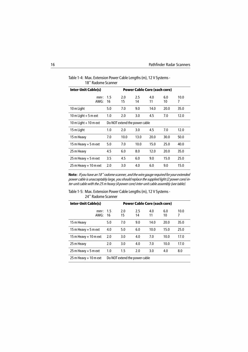
Note: If you have an 18" radome scanner, and the wire gauge required for your extended power cable is unacceptably large, you should replace the supplied light (2 power core) in-ter-unit cable with the 25 m heavy (4 power core) inter-unit cable assembly (see table).
Table 1-4: Max. Extension Power Cable Lengths (m), 12 V Systems - 18" Radome Scanner
Inter-Unit Cable(s) Power Cable Core (each core)
mm2:AWG:
1.516
2.015
2.514
4.011
6.010
10.07
10 m Light 5.0 7.0 9.0 14.0 20.0 35.0
10 m Light + 5 m ext 1.0 2.0 3.0 4.5 7.0 12.0
10 m Light + 10 m ext Do NOT extend the power cable
15 m Light 1.0 2.0 3.0 4.5 7.0 12.0
15 m Heavy 7.0 10.0 13.0 20.0 30.0 50.0
15 m Heavy + 5 m ext 5.0 7.0 10.0 15.0 25.0 40.0
25 m Heavy 4.5 6.0 8.0 12.0 20.0 35.0
25 m Heavy + 5 m ext 3.5 4.5 6.0 9.0 15.0 25.0
25 m Heavy + 10 m ext 2.0 3.0 4.0 6.0 9.0 15.0
Table 1-5: Max. Extension Power Cable Lengths (m), 12 V Systems - 24" Radome Scanner
Inter-Unit Cable(s) Power Cable Core (each core)
mm2:AWG:
1.516
2.015
2.514
4.011
6.010
10.07
15 m Heavy 5.0 7.0 9.0 14.0 20.0 35.0
15 m Heavy + 5 m ext 4.0 5.0 6.0 10.0 15.0 25.0
15 m Heavy + 10 m ext 2.0 3.0 4.0 7.0 10.0 17.0
25 m Heavy 2.0 3.0 4.0 7.0 10.0 17.0
25 m Heavy + 5 m ext 1.0 1.5 2.0 3.0 4.0 8.0
25 m Heavy + 10 m ext Do NOT extend the power cable
17
Open array scanner cables for Pathfinder displays
Inter-unit cable The Pathfinder display inter-unit cables have a connector plug at one end for connecting to the display unit or extension cable; the other end is prepared ready to fit to the power and signal connectors (see Section 2.2).
Heavy duty cables are available in 15 m and 25 m lengths which should be sufficient to complete the cable run required on most small vessels. For longer runs, 5 m and 10 m extension cables are available, both have 4 power cores to minimize voltage drops over the cable run and incorporate in-line moulded plugs.
The maximum inter-unit cable length is limited by the minimum supply voltage and the scanner type.
CAUTION: 10 kW scanner systems cannot be used directly with 12 V systems; they require a 12 V to 24 V converter rated to 180 W. Contact your authorized Raymarine dealer or distributor for details.
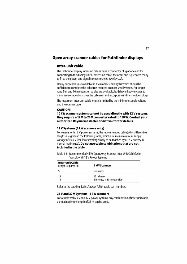
12 V Systems (4 kW scanners only)For vessels with 12 V power systems, the recommended cable(s) for different run lengths are given in the following table, which assumes a minimum supply voltage of 10.7 V (the lowest voltage likely to be reached by a 12 V battery in normal marine use). Do not use cable combinations that are not included in the table.
Refer to the packing list in Section 1.2 for cable part numbers
24 V and 32 V Systems - 4 kW scannersFor vessels with 24 V and 32 V power systems, any combination of inter-unit cable up to a maximum length of 35 m can be used.
Table 1-6: Recommended 4 kW Open Array Scanner Inter-Unit Cable(s) for Vessels with 12 V Power Systems
Inter-Unit CableLength Required (m) 4 kW Scanners
5 5m heavy
1515
15 m heavy5 m heavy + 10 m extension
18 Pathfinder Radar Scanners
24 V and 32 V Systems - 10kW scanners10 kW open array scanners can use any combination of inter-unit cable up to a maximum length of 35 m. However, these systems use considerable power and installations should be planned to minimize all cable lengths. Refer to the tables on page 1-19, Max. Extension Power Cable Lengths (m) - 10 kW Scanner.
Power cableThe open array scanner systems are intended for use on ships’ DC power systems operating in the following ranges:
4 kW 10.7 to 44 V DC range (that is, 12 V, 24 V and 32 V systems)10 kW 20 to 44 V DC range (that is, 24 V and 32 V systems).
CAUTION: Do not use the open array scanner with an SL70, SL70 PLUS, SL70RC PLUS or Autohelm 7" LCD display unit. Failure to observe this may result in permanent damage to the display unit.
10 kW open array scanner systems cannot be used directly with 12 V systems; they require a 12 V to 24 V converter rated to 180 W. Contact your authorized Raymarine dealer or distributor for details.
Open array scanners draw considerable power from the vessels power source, especially in high wind speeds. It is essential for reliable operation that the unit is supplied with a low resistance power cable system, especially when operated from a 12 V power system.
12 V systems (4 kW scanners only)Extensions to the supplied power cable must be kept to a minimum and the power should be fed directly from the output of the battery isolator switch via its own dedicated cable system. It is recommended that no additional power switch is included in this power cable.
CAUTION: The display unit does not include a fuse for scanner power, so an in-line fuse or circuit breaker MUST be included in the power cable.
All power connections must be of high quality to minimize their resistance and to remove the risk of accidental shorts. Recommended maximum power cable extensions are given in the table below. These figures relate to the total cable extension, from the end of the supplied 1.5 m power cable to the system battery terminals. Do not exceed these lengths as unreliable operation may result.
19
Note: If the required extension results in unacceptably large diameter cables, use two or more smaller gauge wires to achieve the required copper wire cross-section. For example, using two pairs of 2 mm2 is equivalent to using two single 4.0 mm2 cables.
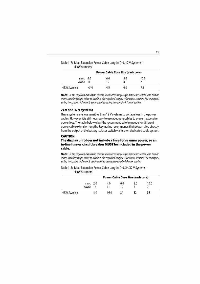
24 V and 32 V systemsThese systems are less sensitive than 12 V systems to voltage loss in the power cables. However, it is still necessary to use adequate cables to prevent excessive power loss. The table below gives the recommended wire gauge for different power cable extension lengths. Raymarine recommends that power is fed directly from the output of the battery isolator switch via its own dedicated cable system.
CAUTION: The display unit does not include a fuse for scanner power, so an in-line fuse or circuit breaker MUST be included in the power cable.
Note: If the required extension results in unacceptably large diameter cables, use two or more smaller gauge wires to achieve the required copper wire cross-section. For example, using two pairs of 2 mm2 is equivalent to using two single 4.0 mm2 cables.
Table 1-7: Max. Extension Power Cable Lengths (m), 12 V Systems - 4 kW scanners
Power Cable Core Size (each core)
mm2:AWG:
4.011
6.010
8.08
10.07
4 kW Scanners <3.0 4.5 6.0 7.5
Table 1-8: Max. Extension Power Cable Lengths (m), 24/32 V Systems - 4 kW Scanners
Power Cable Core Size (each core)
mm2:AWG:
2.014
4.011
6.010
8.08
10.07
4 kW Scanners 8.0 16.0 24 32 35
20 Pathfinder Radar Scanners
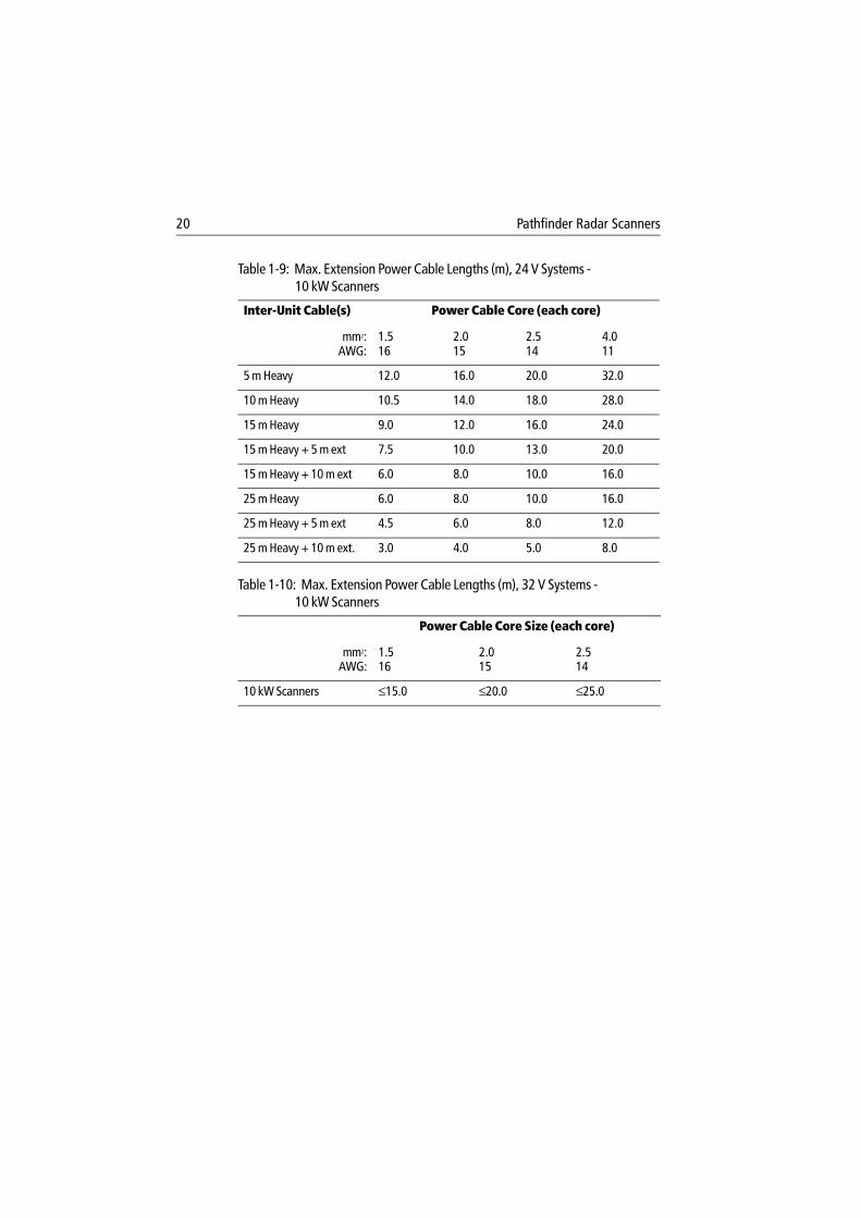
Table 1-9: Max. Extension Power Cable Lengths (m), 24 V Systems - 10 kW Scanners
Inter-Unit Cable(s) Power Cable Core (each core)
mm2:AWG:
1.516
2.015
2.514
4.011
5 m Heavy 12.0 16.0 20.0 32.0
10 m Heavy 10.5 14.0 18.0 28.0
15 m Heavy 9.0 12.0 16.0 24.0
15 m Heavy + 5 m ext 7.5 10.0 13.0 20.0
15 m Heavy + 10 m ext 6.0 8.0 10.0 16.0
25 m Heavy 6.0 8.0 10.0 16.0
25 m Heavy + 5 m ext 4.5 6.0 8.0 12.0
25 m Heavy + 10 m ext. 3.0 4.0 5.0 8.0
Table 1-10: Max. Extension Power Cable Lengths (m), 32 V Systems - 10 kW Scanners
Power Cable Core Size (each core)
mm2:AWG:
1.516
2.015
2.514
10 kW Scanners ≤15.0 ≤20.0 ≤25.0
21
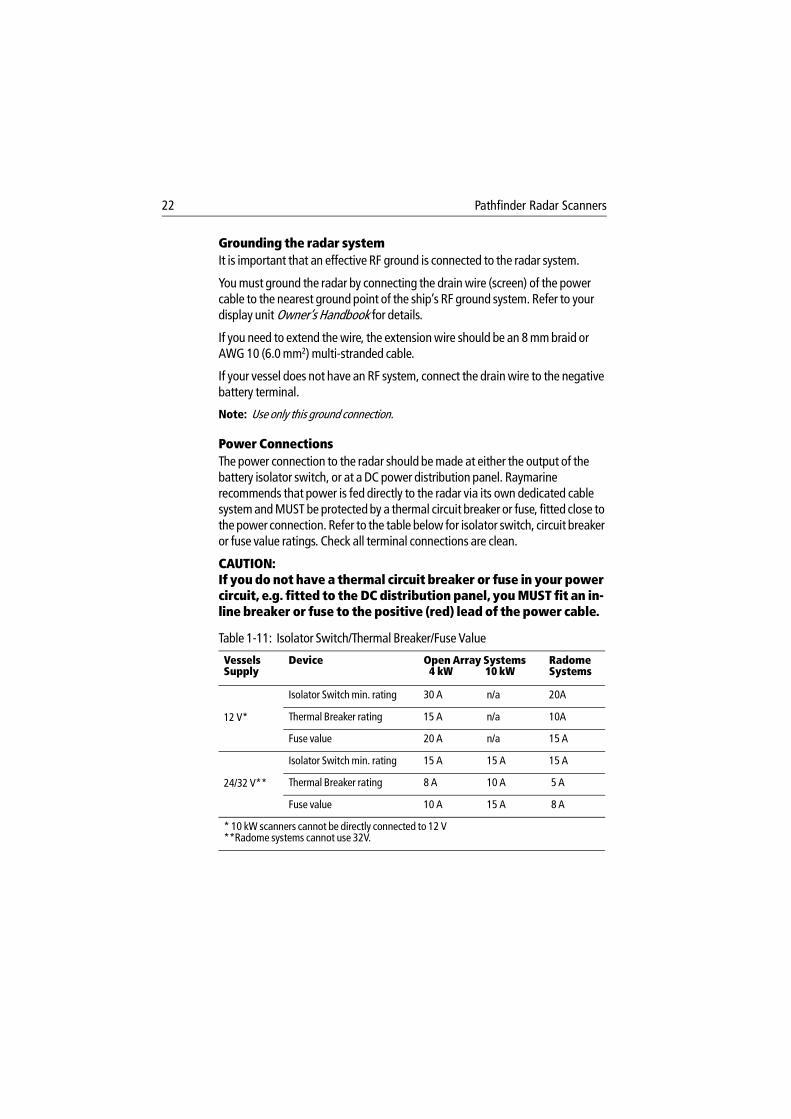
Open array scanner cables for C-series displaysA split pedestal cable is required to connect a compatible open array scanner to the display unit and to the power source. If you are connecting an existing compatible scanner to a C-Series display a pedestal adaptor cable can be used instead of the split pedestal cable.
CAUTION: Do not extend the split pedestal or pedestal adaptor cable.
Split pedestal cableThe split pedestal cable combines the inter-unit and power cores, divided by a Y junction. One core has a connector plug for connecting to the display unit, the other core is for connecting to power. The scanner end is prepared ready to fit to the power and signal connectors (see Section 2.2).
Two cable lengths are available:
• 25m cable provides 25m from scanner to Y junction.• 15m cable provides 15m from scanner to Y junction.
These lengths should be sufficient to complete the cable run required on most small vessels.
Pedestal adaptor cableThe pedestal adaptor cable combines the inter-unit and power cores, divided by a Y junction. One core has a connector plug for connecting to the display unit, the other core is for connecting to power. The scanner end has a connector plug for fitting to an existing inter-unit cable.
1.5 Power RequirementsNote: Open array scanners connected to a Pathfinder display and all radome scanners re-ceive power from the display unit via the inter-unit cable. The display power cable is sup-plied with the display unit and details for connecting power are provided in your display unit Owner’s Handbook. However, you should be aware of the information provided in this section.
The DC system should be either:
• Negative grounded, with the negative battery terminal connected to the ship’s ground.
• Floating, with neither battery terminal connected to the ship’s ground.
CAUTION: This radar is not intended for use on “positive” ground vessels.The power cable Earth screen connections must be connected to the ship’s ground.
22 Pathfinder Radar Scanners
Grounding the radar systemIt is important that an effective RF ground is connected to the radar system.
You must ground the radar by connecting the drain wire (screen) of the power cable to the nearest ground point of the ship’s RF ground system. Refer to your display unit Owner’s Handbook for details.
If you need to extend the wire, the extension wire should be an 8 mm braid or AWG 10 (6.0 mm2) multi-stranded cable.
If your vessel does not have an RF system, connect the drain wire to the negative battery terminal.
Note: Use only this ground connection.
Power ConnectionsThe power connection to the radar should be made at either the output of the battery isolator switch, or at a DC power distribution panel. Raymarine recommends that power is fed directly to the radar via its own dedicated cable system and MUST be protected by a thermal circuit breaker or fuse, fitted close to the power connection. Refer to the table below for isolator switch, circuit breaker or fuse value ratings. Check all terminal connections are clean.
CAUTION: If you do not have a thermal circuit breaker or fuse in your power circuit, e.g. fitted to the DC distribution panel, you MUST fit an in-line breaker or fuse to the positive (red) lead of the power cable.
Table 1-11: Isolator Switch/Thermal Breaker/Fuse Value
VesselsSupply
Device Open Array Systems4 kW 10 kW
RadomeSystems
12 V*
Isolator Switch min. rating 30 A n/a 20A
Thermal Breaker rating 15 A n/a 10A
Fuse value 20 A n/a 15 A
24/32 V**
Isolator Switch min. rating 15 A 15 A 15 A
Thermal Breaker rating 8 A 10 A 5 A
Fuse value 10 A 15 A 8 A
* 10 kW scanners cannot be directly connected to 12 V **Radome systems cannot use 32V.
23
Chapter 2: Installing the Scanner
2.1 Radome scanner
Securing the radome scanner to the mounting sur-face
CAUTION: The drain tube must always be used, but may be shortened if necessary
1. Using the paper template supplied with the scanner mounting kit, mark the flat mounting surface with the mounting holes and drain tube hole, and drill the holes as indicated on the template.If it is impractical to drill a hole for the drain tube, then the scanner unit should be mounted on 4 suitable spacers 10 mm high and the drain tube length reduced by 10 mm. It will then be clear of the flat surface and can still perform its function.
Notes: (1) If you are using a Raymarine mast mount bracket, the surface is pre-pre-pared.
(2) If you are mounting the scanner on a flat surface, you may find it easier to fit the drain tube, as described in the following section, before securing the scanner.
2. Position the scanner on the mounting surface, ensuring that the cable inlet is pointing aft.
3. Locate the bolts and washers supplied with the scanner and grease the bolts. Fix the bitumen washers to the mounting surface then secure the scanner to the mounting surface as shown in the following diagram. Tighten the bolts to 20 Nm (14.7 lb ft.); ensure the scanner is tightly fitted.
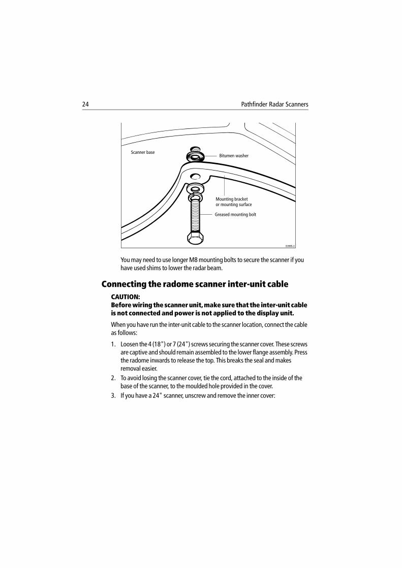
24 Pathfinder Radar Scanners
You may need to use longer M8 mounting bolts to secure the scanner if you have used shims to lower the radar beam.
Connecting the radome scanner inter-unit cableCAUTION: Before wiring the scanner unit, make sure that the inter-unit cable is not connected and power is not applied to the display unit.
When you have run the inter-unit cable to the scanner location, connect the cable as follows:
1. Loosen the 4 (18") or 7 (24") screws securing the scanner cover. These screws are captive and should remain assembled to the lower flange assembly. Press the radome inwards to release the top. This breaks the seal and makes removal easier.
2. To avoid losing the scanner cover, tie the cord, attached to the inside of the base of the scanner, to the moulded hole provided in the cover.
3. If you have a 24" scanner, unscrew and remove the inner cover:
Scanner base
Mounting bracketor mounting surface
Greased mounting bolt
D3995-3
Bitumen washer
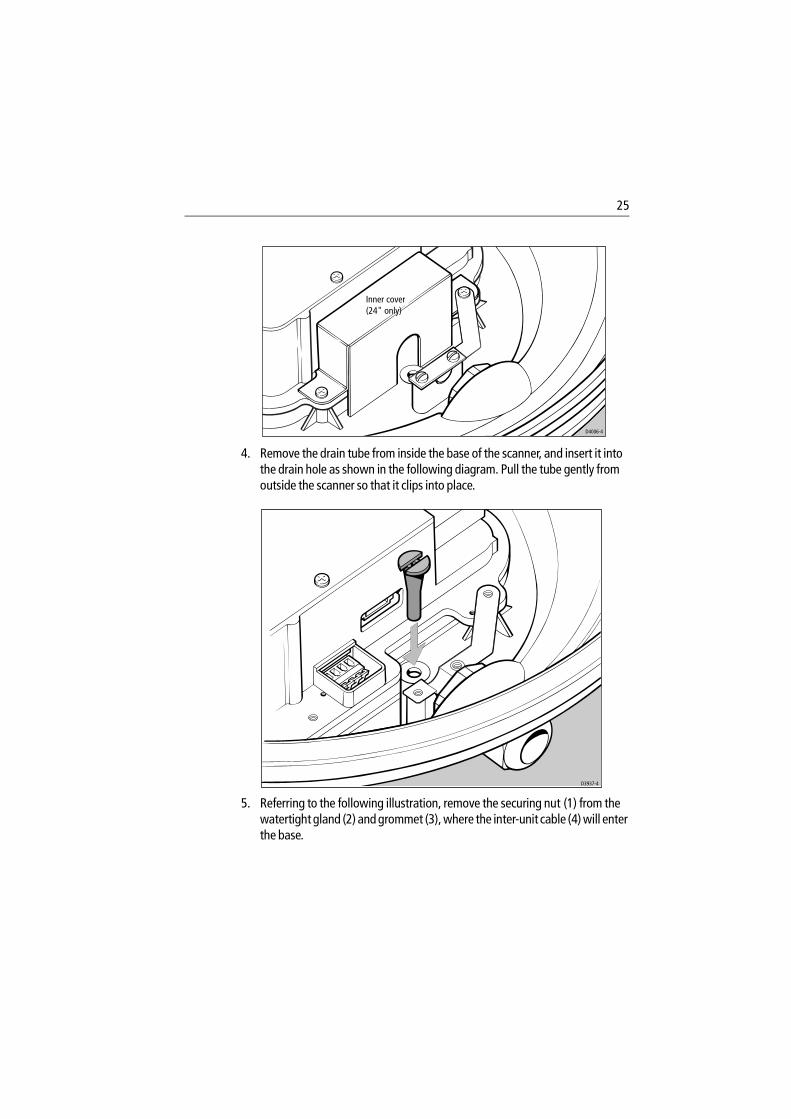
25
4. Remove the drain tube from inside the base of the scanner, and insert it into the drain hole as shown in the following diagram. Pull the tube gently from outside the scanner so that it clips into place.
5. Referring to the following illustration, remove the securing nut (1) from the watertight gland (2) and grommet (3), where the inter-unit cable (4) will enter the base.
D4006-4
Inner cover(24" only)
D3937-4
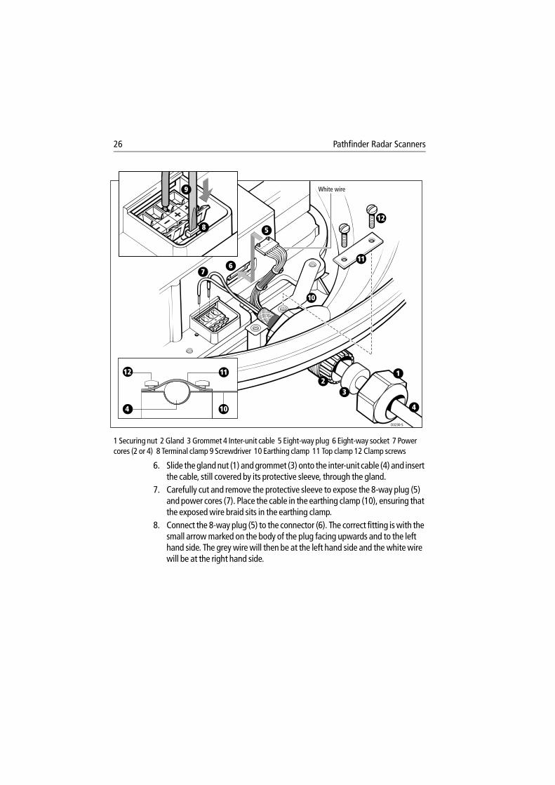
26 Pathfinder Radar Scanners
1 Securing nut 2 Gland 3 Grommet 4 Inter-unit cable 5 Eight-way plug 6 Eight-way socket 7 Power cores (2 or 4) 8 Terminal clamp 9 Screwdriver 10 Earthing clamp 11 Top clamp 12 Clamp screws
6. Slide the gland nut (1) and grommet (3) onto the inter-unit cable (4) and insert the cable, still covered by its protective sleeve, through the gland.
7. Carefully cut and remove the protective sleeve to expose the 8-way plug (5) and power cores (7). Place the cable in the earthing clamp (10), ensuring that the exposed wire braid sits in the earthing clamp.
8. Connect the 8-way plug (5) to the connector (6). The correct fitting is with the small arrow marked on the body of the plug facing upwards and to the left hand side. The grey wire will then be at the left hand side and the white wire will be at the right hand side.
D3230-5
4 10
1112
White wire
23
1
10
11
12
5
67
8
9
4
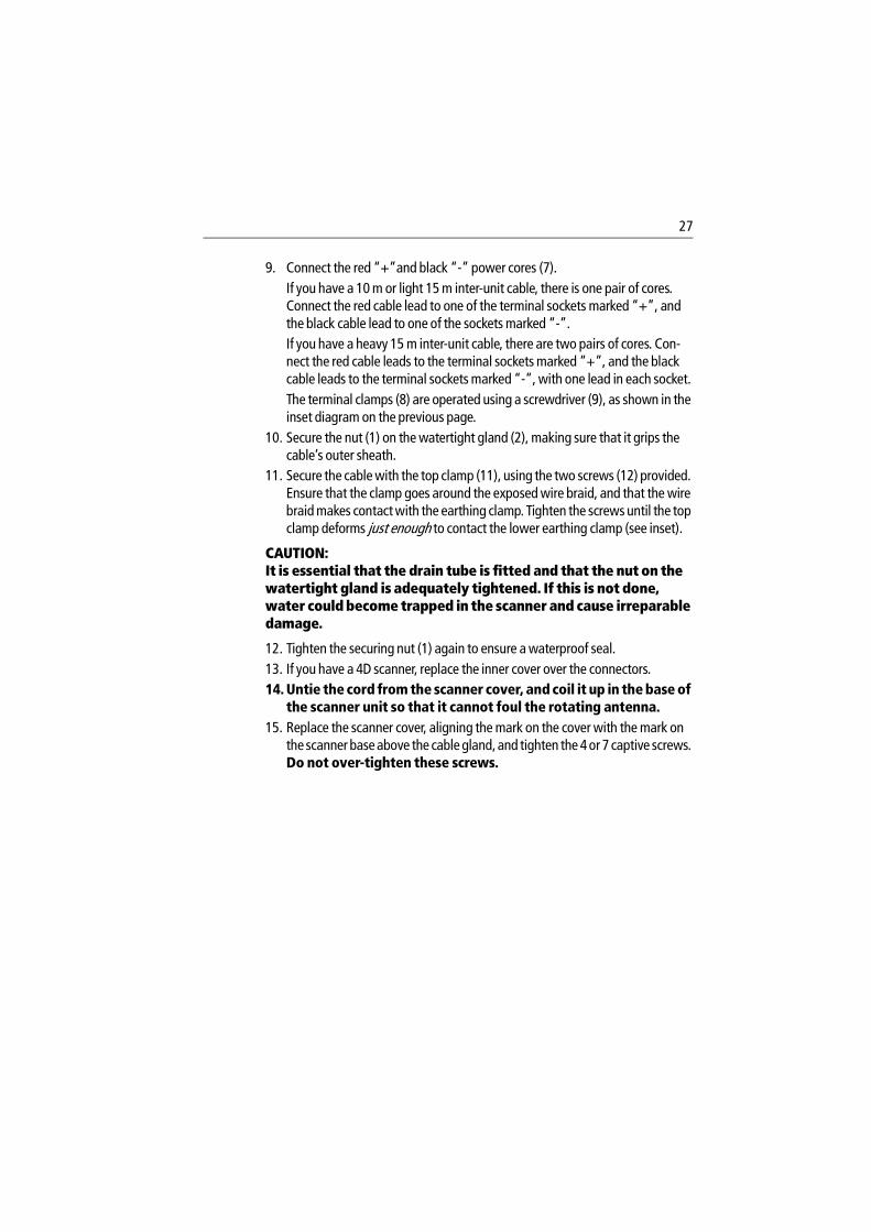
27
9. Connect the red “+”and black “-” power cores (7).If you have a 10 m or light 15 m inter-unit cable, there is one pair of cores. Connect the red cable lead to one of the terminal sockets marked “+”, and the black cable lead to one of the sockets marked “-”.If you have a heavy 15 m inter-unit cable, there are two pairs of cores. Con-nect the red cable leads to the terminal sockets marked “+”, and the black cable leads to the terminal sockets marked “-”, with one lead in each socket.The terminal clamps (8) are operated using a screwdriver (9), as shown in the inset diagram on the previous page.
10. Secure the nut (1) on the watertight gland (2), making sure that it grips the cable’s outer sheath.
11. Secure the cable with the top clamp (11), using the two screws (12) provided. Ensure that the clamp goes around the exposed wire braid, and that the wire braid makes contact with the earthing clamp. Tighten the screws until the top clamp deforms just enough to contact the lower earthing clamp (see inset).
CAUTION: It is essential that the drain tube is fitted and that the nut on the watertight gland is adequately tightened. If this is not done, water could become trapped in the scanner and cause irreparable damage.
12. Tighten the securing nut (1) again to ensure a waterproof seal.13. If you have a 4D scanner, replace the inner cover over the connectors.14. Untie the cord from the scanner cover, and coil it up in the base of
the scanner unit so that it cannot foul the rotating antenna.15. Replace the scanner cover, aligning the mark on the cover with the mark on
the scanner base above the cable gland, and tighten the 4 or 7 captive screws. Do not over-tighten these screws.
28 Pathfinder Radar Scanners
2.2 Open array scannerInstallation of the open array scanner should only be undertaken by a competent installer. If you have any difficulty with the installation, please contact your local Raymarine dealer or distributor.
The open array scanner is supplied in two sections; the pedestal unit and the antenna. The pedestal unit is secured from below the mounting platform. The open array is then secured to the pedestal. Full details for mounting the scanner are given below.
CAUTION: The pedestal unit has a cap fitted over the open array mounting shaft to protect the protuding co-axial pin. This cap must be left in place until the open array is fitted.The pedestal base is fitted with a seal: DO NOT grease this seal.
WARNING: The open array scanner weighs: 48" scanner - 30 kg (66.2 lb); 72" scanner - 33.4 kg (73.7 lb). For safety reasons it is recommended that the unit is not lifted by one person.The unit is fitted with lifting eyes (maximum SWL 40 kg) to facilitate the use of standard lifting accessories, e.g. rope, chain or strop. The safe working load (SWL) of the lifting accessories should be 150 kg. Suitable lifting equipment could include a crane, hoist, or an appropriate rigid, overhead structure.Alternatively, the unit is suitable for a two person lift. Care must be taken to ensure that each person is standing on a stable surface, and that the pedestal is held carefully to ensure it cannot slip. The T-bar beneath the open array antenna can be used to aid lifting.You should never lift the scanner by holding onto the open array antenna.
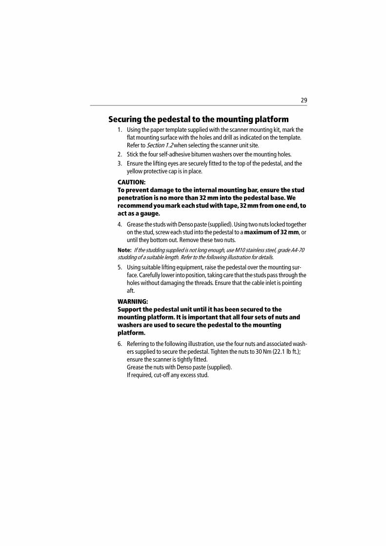
29
Securing the pedestal to the mounting platform1. Using the paper template supplied with the scanner mounting kit, mark the
flat mounting surface with the holes and drill as indicated on the template. Refer to Section 1.2 when selecting the scanner unit site.
2. Stick the four self-adhesive bitumen washers over the mounting holes.3. Ensure the lifting eyes are securely fitted to the top of the pedestal, and the
yellow protective cap is in place.
CAUTION: To prevent damage to the internal mounting bar, ensure the stud penetration is no more than 32 mm into the pedestal base. We recommend you mark each stud with tape, 32 mm from one end, to act as a gauge.
4. Grease the studs with Denso paste (supplied). Using two nuts locked together on the stud, screw each stud into the pedestal to a maximum of 32 mm, or until they bottom out. Remove these two nuts.
Note: If the studding supplied is not long enough, use M10 stainless steel, grade A4-70 studding of a suitable length. Refer to the following illustration for details.
5. Using suitable lifting equipment, raise the pedestal over the mounting sur-face. Carefully lower into position, taking care that the studs pass through the holes without damaging the threads. Ensure that the cable inlet is pointing aft.
WARNING: Support the pedestal unit until it has been secured to the mounting platform. It is important that all four sets of nuts and washers are used to secure the pedestal to the mounting platform.
6. Referring to the following illustration, use the four nuts and associated wash-ers supplied to secure the pedestal. Tighten the nuts to 30 Nm (22.1 lb ft.); ensure the scanner is tightly fitted.Grease the nuts with Denso paste (supplied).If required, cut-off any excess stud.
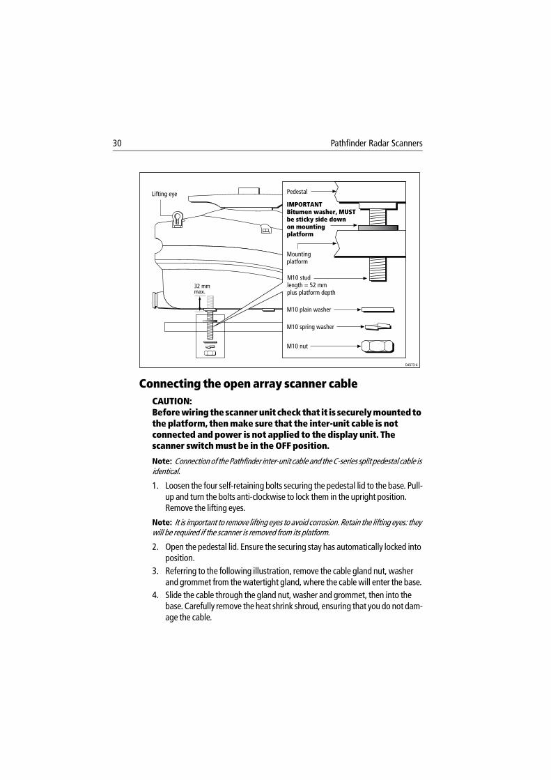
30 Pathfinder Radar Scanners
Connecting the open array scanner cableCAUTION: Before wiring the scanner unit check that it is securely mounted to the platform, then make sure that the inter-unit cable is not connected and power is not applied to the display unit. The scanner switch must be in the OFF position.
Note: Connection of the Pathfinder inter-unit cable and the C-series split pedestal cable is identical.
1. Loosen the four self-retaining bolts securing the pedestal lid to the base. Pull-up and turn the bolts anti-clockwise to lock them in the upright position. Remove the lifting eyes.
Note: It is important to remove lifting eyes to avoid corrosion. Retain the lifting eyes: they will be required if the scanner is removed from its platform.
2. Open the pedestal lid. Ensure the securing stay has automatically locked into position.
3. Referring to the following illustration, remove the cable gland nut, washer and grommet from the watertight gland, where the cable will enter the base.
4. Slide the cable through the gland nut, washer and grommet, then into the base. Carefully remove the heat shrink shroud, ensuring that you do not dam-age the cable.
Lifting eye
32 mm max.
D4573-4
Pedestal
IMPORTANTBitumen washer, MUSTbe sticky side downon mountingplatform
Mountingplatform
M10 plain washer
M10 spring washer
M10 studlength = 52 mmplus platform depth
M10 nut
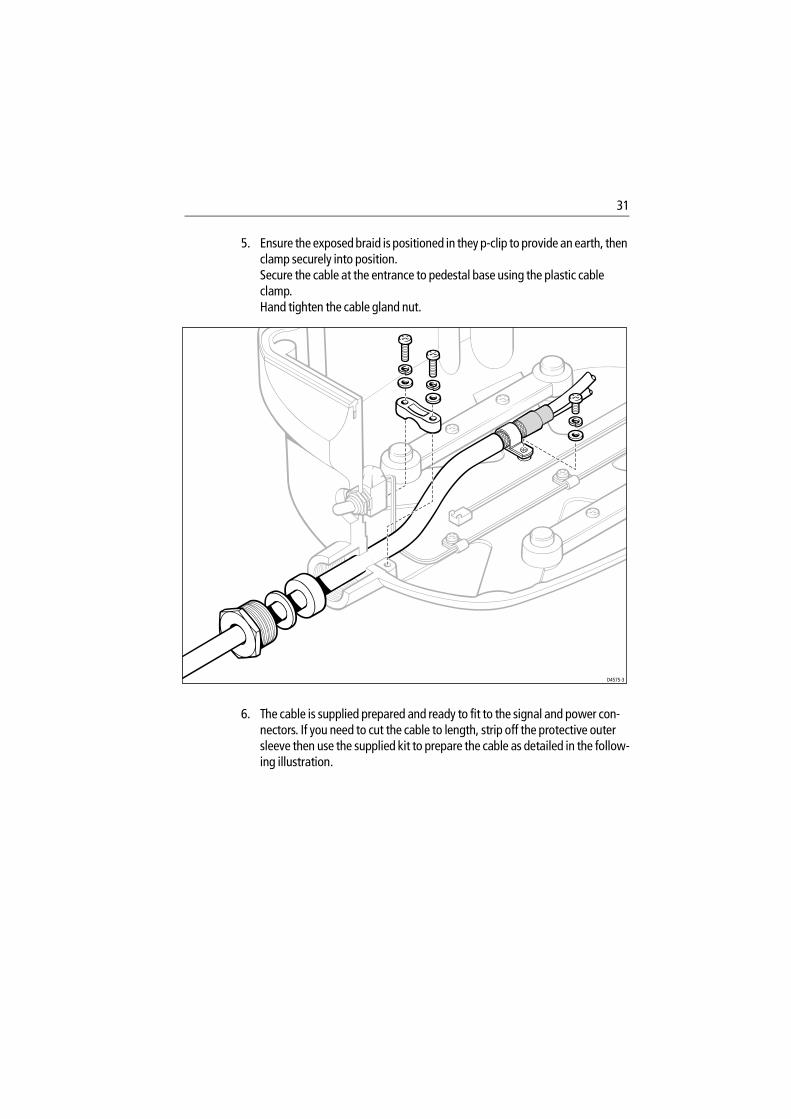
31
5. Ensure the exposed braid is positioned in they p-clip to provide an earth, then clamp securely into position. Secure the cable at the entrance to pedestal base using the plastic cable clamp. Hand tighten the cable gland nut.
.
6. The cable is supplied prepared and ready to fit to the signal and power con-nectors. If you need to cut the cable to length, strip off the protective outer sleeve then use the supplied kit to prepare the cable as detailed in the follow-ing illustration.
D4575-3
32 Pathfinder Radar Scanners
CAUTION: If any of the wires are incorrectly fitted, the scanner will not function correctly.
7. Fit the 8-way plug (supplied in the kit of parts) to the cable as shown in the fol-lowing diagram. The terminal clamps are operated using a screwdriver as shown. Connect the plug to the signal connector as shown. When correctly fitted the white wire (co-axial) will be at the outer edge of the unit.
500 mm ± 10 mm
500 mm ± 10 mm
35 mm
30 mm15 mm
Black power wires
Data wires(6 off)
Coaxialsignal
Coaxialscreen
Red power wires
25 mm
10 mm
See Note B
See Note A
Exposed braid
Exposed braid
Exposed braid
5-6 mm strip length
5-6 mmstrip length
5mm maximum
25 mm
35 mm
25 mm
35 mm
1. Preparation of Wires
2. Heat Shrinking of Wires
3. Preparation of Earthing Braid
Apply heatshrink ensuring at least 15 mm of braid is visible.When clamped in position the braid should make full contact with the P-clip.
Heatshrink
Form the wires into two bundles with heat-shrink tubing(one containing the four power wires and the other containing the eight signal wires).
Notes A. Aluminium screen/polyester tape screen to remain.B. Heat shrink sleeving fitted to keep the aluminium/polyester tape screen from
unwinding from the coaxial signal insulation.
D4579-3
1. Remove the protective sleeve to a length of 535 mm ± 10 mm.2. Using wire cutters, carefully remove the earthing braid to a length of 500 mm ± 10 mm.3. Prepare co-axial wire as shown.
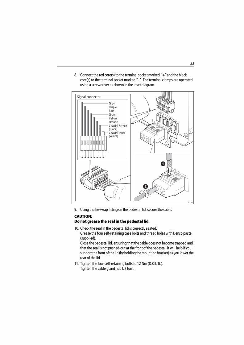
33
8. Connect the red core(s) to the terminal socket marked “+”and the black core(s) to the terminal socket marked “-”. The terminal clamps are operated using a screwdriver as shown in the inset diagram.
9. Using the tie-wrap fitting on the pedestal lid, secure the cable.
CAUTION: Do not grease the seal in the pedestal lid.
10. Check the seal in the pedestal lid is correctly seated.Grease the four self-retaining case bolts and thread holes with Denso paste (supplied).Close the pedestal lid, ensuring that the cable does not become trapped and that the seal is not pushed-out at the front of the pedestal: it will help if you support the front of the lid (by holding the mounting bracket) as you lower the rear of the lid.
11. Tighten the four self-retaining bolts to 12 Nm (8.8 lb ft.). Tighten the cable gland nut 1/2 turn.
2
1
GreyPurpleBlueGreenYellowOrangeCoaxial Screen (Black)Coaxial Inner (White)
Signal connector
D6276-1
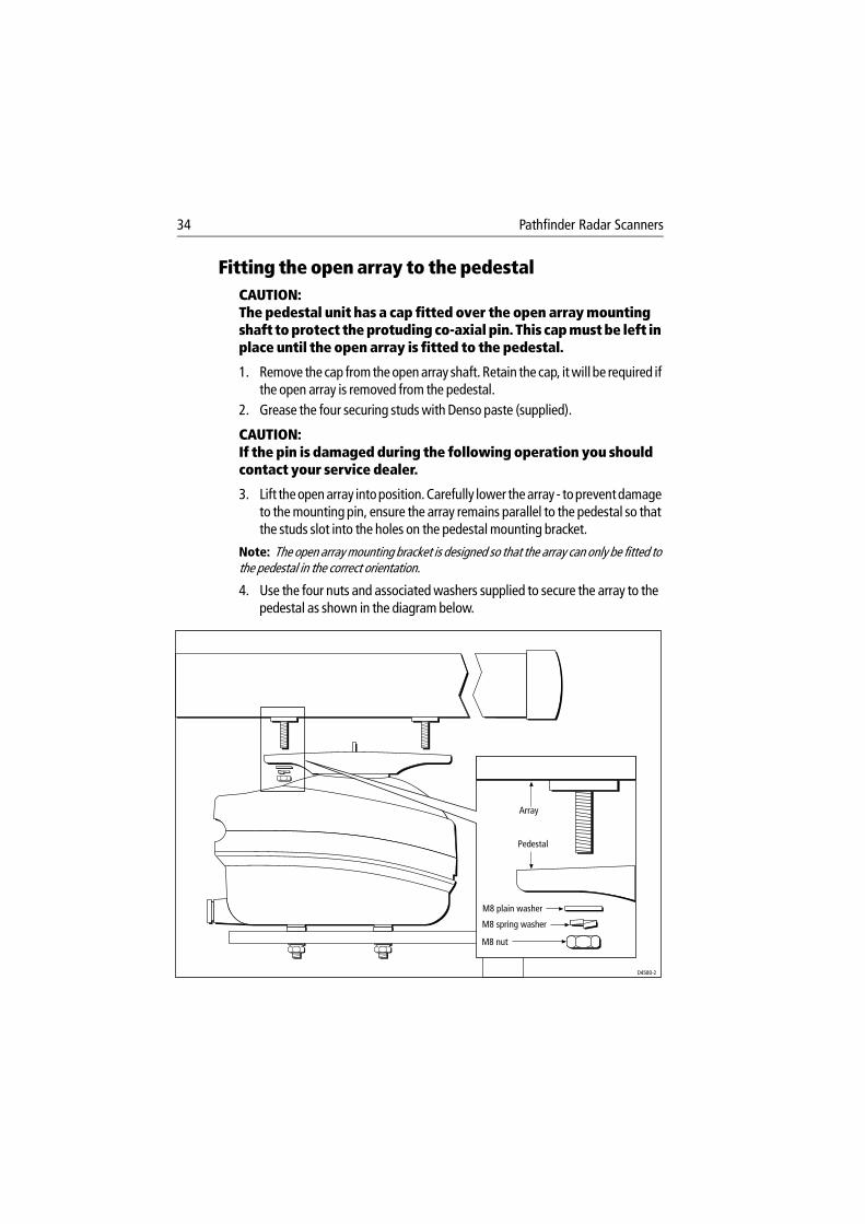
34 Pathfinder Radar Scanners
Fitting the open array to the pedestalCAUTION: The pedestal unit has a cap fitted over the open array mounting shaft to protect the protuding co-axial pin. This cap must be left in place until the open array is fitted to the pedestal.
1. Remove the cap from the open array shaft. Retain the cap, it will be required if the open array is removed from the pedestal.
2. Grease the four securing studs with Denso paste (supplied).
CAUTION: If the pin is damaged during the following operation you should contact your service dealer.
3. Lift the open array into position. Carefully lower the array - to prevent damage to the mounting pin, ensure the array remains parallel to the pedestal so that the studs slot into the holes on the pedestal mounting bracket.
Note: The open array mounting bracket is designed so that the array can only be fitted to the pedestal in the correct orientation.
4. Use the four nuts and associated washers supplied to secure the array to the pedestal as shown in the diagram below.
M8 plain washer
M8 spring washer
M8 nut
Array
Pedestal
D4580-2
35
2.3 System ConnectionsCAUTION: The display connector on the scanner cable is a moulded plug that cannot be replaced. DO NOT remove this moulded plug.
Do not use an open array scanner with an SL70, SL70 PLUS or SL70RC PLUS 7" LCD display unit. Failure to observe this may result in permanent damage to the display unit.
10 kW open array scanners cannot be directly connected to 12 V systems.
Scanner ConnectionsThe inter-unit or split pedestal cable is connected to the scanner as previously described in Connecting the radome scanner inter-unit cable on page 24 or Connecting the open array scanner cable on page 30.
Display ConnectionsThe inter-unit or split pedestal cable is connected to the display unit with the moulded plug; the following illustration identifies the scanner connector on the various display connector panels.
If you are using an inter-unit extension cable, connect this to the display unit, and connect the supplied cable to the extension cable.
You cannot extend the split pedestal cable or pedestal adaptor cable.
Power ConnectionsDC power requirements are described in Section 1.5, Power Requirements.
Power for an open array scanner connected to a Pathfinder display and for any radome scanner is supplied via the display unit - refer to your Display Unit Owner’s Handbook for connection details.
An open array scanner is connected to a C-Series display via the split pedestal or adapator cable.You must use the pedestal adapter cable to connect a C-Series display to an existing open array scanner unit with a standard inter-unit cable; connect the adaptor between the inter-unit cable and the display.
The following connections to the boat’s DC power are required:
Red Battery +ve (12/24 V)Black Battery -ve (0 v)Green Ground
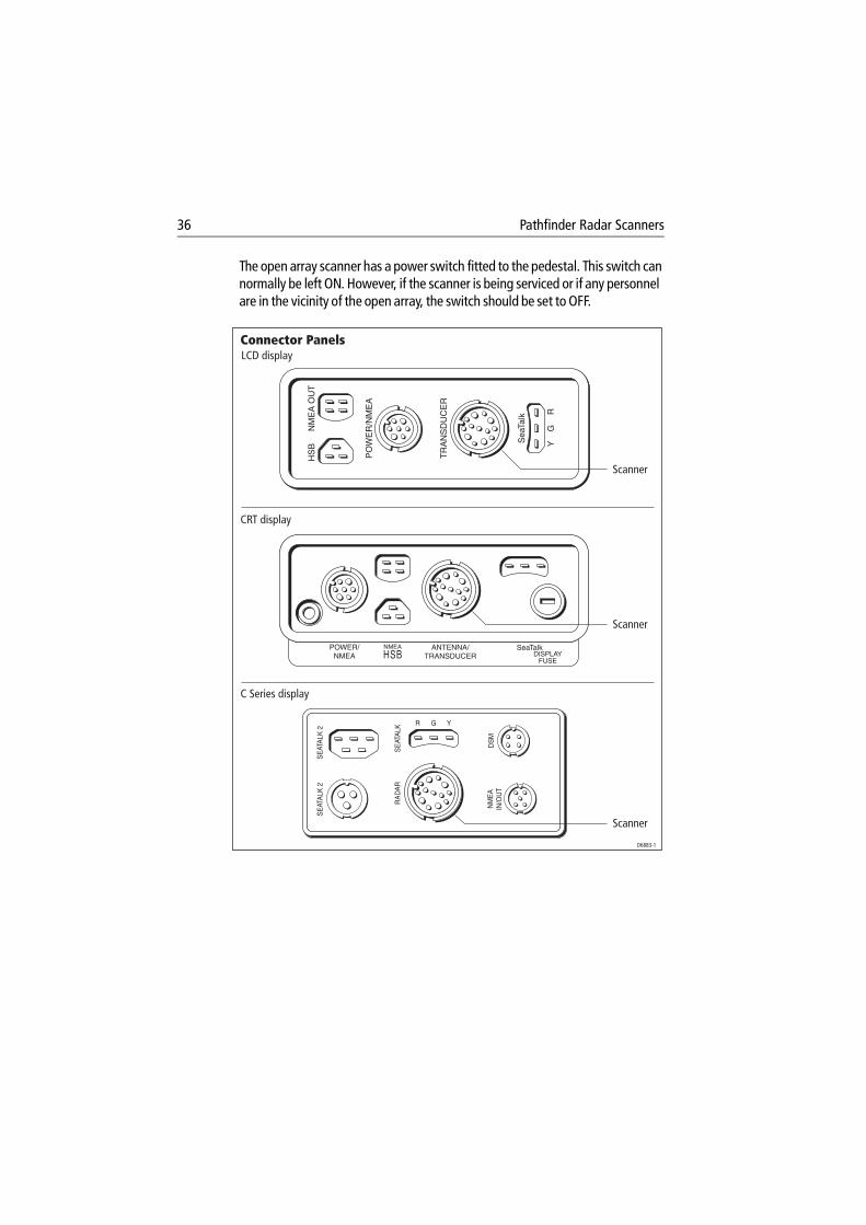
36 Pathfinder Radar Scanners
The open array scanner has a power switch fitted to the pedestal. This switch can normally be left ON. However, if the scanner is being serviced or if any personnel are in the vicinity of the open array, the switch should be set to OFF.
YG
Sea
Talk
TR
AN
SD
UC
ER
PO
WE
R/N
ME
A
HS
BN
ME
A O
UT
R
NM
EA
IN/O
UT
DS
M
SE
ATA
LKR
AD
AR
SE
ATA
LK 2
SE
ATA
LK 2
R G Y
POWER/NMEA
ANTENNA/TRANSDUCER
NMEA SeaTalkDISPLAY
FUSEHSB
LCD display
Scanner
CRT display
C Series display
D6883-1
Connector Panels
Scanner
Scanner
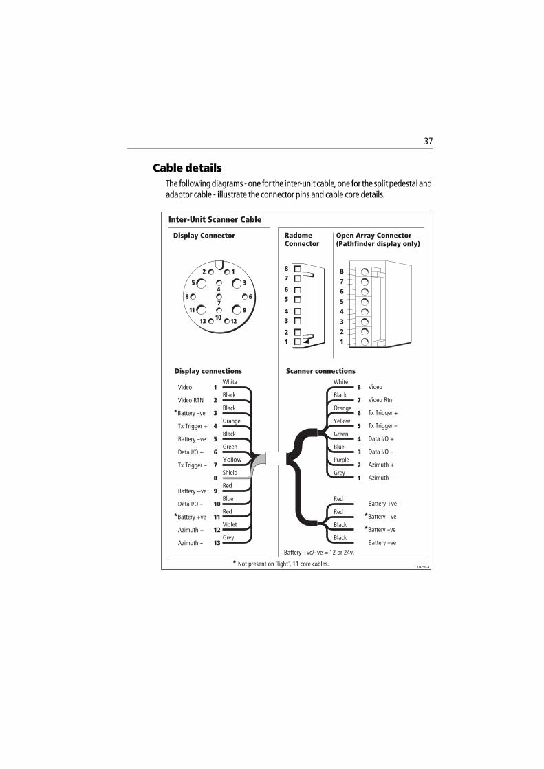
37
Cable detailsThe following diagrams - one for the inter-unit cable, one for the split pedestal and adaptor cable - illustrate the connector pins and cable core details.
12
354
7
1011
8 6
9
13 12
Black
White
Orange
Black
Black
Green
Yellow
Shield
Red
Red
Violet
Blue
Grey
Video
Video RTN
*Battery --ve
Tx Trigger +
Battery --ve
Data I/O +
Tx Trigger --
Battery +ve
Data I/O --
*Battery +ve
Azimuth +
Azimuth --
1
2
3
4
5
6
7
8
9
10
11
12
13
8
7
6
5
4
3
2
1
87654321
White
Black
Orange
Yellow
Green
Blue
Purple
Grey
Red
Red
Black
Black
Video
Video Rtn
Tx Trigger +
Tx Trigger --
Data I/O +
Data I/O --
Azimuth +
Azimuth --
Battery +ve
*Battery +ve
*Battery --ve
Battery --ve
RadomeConnector
Open Array Connector(Pathfinder display only)
Display Connector
Inter-Unit Scanner Cable
Display connections Scanner connections
* Not present on 'light', 11 core cables.
Battery +ve/--ve = 12 or 24v.
D4290-4
2 1
4 3
6 5
8 7
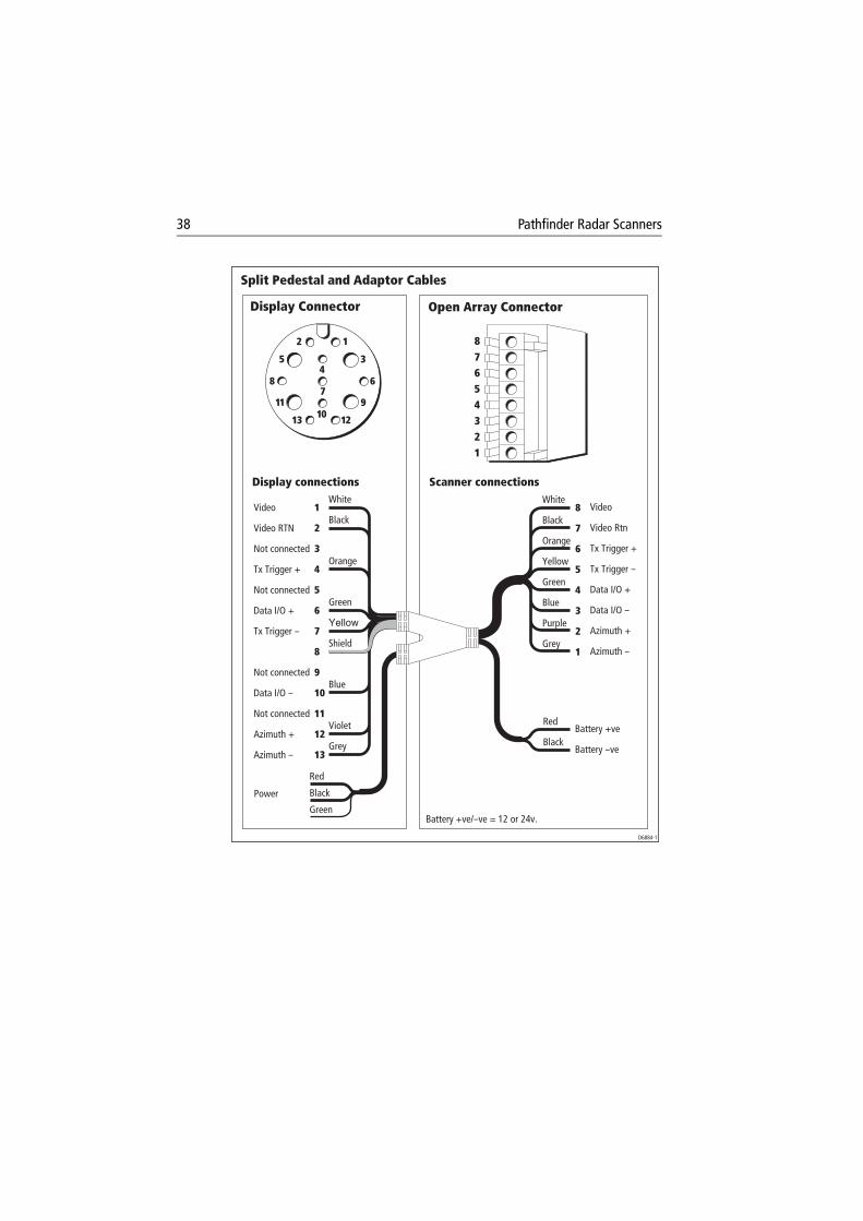
38 Pathfinder Radar Scanners
12
354
7
1011
8 6
9
13 12
White
Orange
Black
Green
Yellow
Shield
Violet
Blue
Grey
Video
Video RTN
Not connected
Tx Trigger +
Not connected
Data I/O +
Tx Trigger --
Not connected
Data I/O --
Not connected
Azimuth +
Azimuth --
1
2
3
4
5
6
7
8
9
10
11
12
13
8
7
6
5
4
3
2
1
87654321
White
Black
Orange
Yellow
Green
Blue
Purple
Grey
Red
Black
Red
Black
Green
Power
Video
Video Rtn
Tx Trigger +
Tx Trigger --
Data I/O +
Data I/O --
Azimuth +
Azimuth --
Battery +ve
Battery --ve
Display Connector
Split Pedestal and Adaptor Cables
Open Array Connector
Display connections Scanner connections
Battery +ve/--ve = 12 or 24v.
D6884-1
39
Chapter 3: Post Installation Checks and Maintenance
Once you have installed your radar scanner and display unit, and made all the connections, you need to check your installation. You can then set up the radar system, align the scanner and check the display timing. In addition, for a 72" open array scanner you need to set the antenna size to ensure the scanner rests in the correct position when rotation stops.
Set up, alignment and timing checks are performed from the radar system display unit. The procedures are outlined below; full details are provided in the display unit Owner’s Handbook. You should read the Pathfinder radar display unit Owner’s Handbook and familiarize yourself with the operation of the radar.
EMC ConformanceAlways check the installation before going to sea to make sure that it is not affected by radio transmissions, engine starting etc.
3.1 System Checks and Alignment
System checkBefore performing the functional test, check the following:
• All securing bolts are fully tightened and mechanical locking arrangements as specified are in place
• All connections have been made• All connecting wires are secured and protected as necessary
Note: If you are the boat owner and have performed the installation yourself, ask your au-thorized installation dealer to check the installation before going to sea.
Set up, alignment and timing checks
Switch on and initial set upOn the open array scanner, ensure the power switch on the pedestal is set to ON.To switch on the display unit, press and hold the POWER key until the unit beeps. The magnetron warm-up sequence should start, after which the unit should enter Standby mode. If necessary, adjust the lighting and contrast.If required, change the default language settings.
40 Pathfinder Radar Scanners
Checking transmissionWARNING: The radar scanner transmits electromagnetic energy. Ensure that the scanner has been installed according to the recommendations given in Chapter 1, and that all personnel are clear of the scanner, before switching to transmit mode.
Run through the radar operations described in the display unit Owner’s Handbook and check that all the expected data is displayed.
Bearing alignmentWhen the system is correctly installed, you must check the bearing alignment to ensure that targets appear at their correct bearing relative to the ship’s bow, and adjust the alignment if necessary.
Display timing adjustmentThe display timing can be affected by the length of the cable used to connect the scanner to the display unit. This in turn affects the short range accuracy shown on the display. It is advisable to check the display timing before using the system for navigation.
72" open array position alignmentTo ensure the 72" open array scanner rests in correct position when rotation stops, you need to adjust the radar set up as follows:
1. With the display switched on in Radar mode, press MENU then press the RADAR SET UP soft key.
2. Use the cursor to select the ANTENNA SIZE option, then press the 6 ft soft key.Press ENTER twice to return to the default display.If the Radar Set Up menu option ANTENNA SIZE is not available, then you have an older version of display software. The 72" open array scanner will operate correctly with this display. However, for details on adjusting the open array stopping-position, please contact your authorized Raymarine dealer or distributor.
41
3.2 Maintenance
WarningsThe display unit and scanner unit contain high voltage. Adjustments require specialized service procedures and tools only available to qualified service technicians - there are no user serviceable parts or adjustments and the operator should not attempt to service the equipment. The operator should not remove the rear cover of the display or any internal covers in the scanner.
Always turn the radar system off before carrying out any routine maintenance on the scanner or nearby equipment. Switch off the display unit before removing the power cord.
Routine ChecksThe radar scanners are sealed units. Maintenance procedures are therefore limited to the following periodical checks:
• Examine the cables for signs of damage, such as chafing, cuts or nicks.• Check that the cable connectors are firmly attached.• Make sure the scanner and pedestal are still attached securely to the mount-
ing.• Once a year, remove, grease and re-attach the mounting bolts securing the
scanner and pedestal.
Servicing and Safety• Raymarine equipment should be serviced only by authorized Raymarine ser-
vice technicians. They will ensure that service procedures and replacement parts used will not affect performance. There are no user serviceable parts in any Raymarine product.
• Some products generate high voltages, so never handle the cables/connec-tors when power is being supplied to the equipment.
• When powered, all electrical equipment produces electromagnetic fields. These can cause adjacent pieces of electrical equipment to interact with one another, with a consequent adverse effect on operation. In order to minimize these effects and enable you to get the best possible performance from your Raymarine equipment, guidelines are given in the installation instructions, to enable you to ensure minimum interaction between different items of equip-ment, i.e. ensure optimum Electromagnetic Compatibility (EMC).
42 Pathfinder Radar Scanners
• Always report any EMC-related problem to your nearest Raymarine dealer. We use such information to improve our quality standards.
• In some installations, it may not be possible to prevent the equipment from being affected by external influences. In general this will not damage the equipment but it can lead to spurious resetting action, or momentarily may result in faulty operation.
3.3 Problem SolvingAll Raymarine products are subjected to comprehensive test and quality assurance programmes prior to packing and shipping. However, if this unit should develop a fault, please refer to the following table to identify the most likely cause and the corrective action required to restore normal operation.
If you still have a problem after referring to the table below, contact your local dealer, national distributor or Raymarine Product Support Department for further advice.
Always quote the product serial numbers. The display unit serial number is printed on the back of the unit, and the scanner serial number is on the back of the scanner near the gland.
Table 3-1: Common Problems and Their Solutions
Problem Correction
“Scanner not responding” mes-sage.
Check that the cable connecting the scanner to the radar display unit is firmly attached and undamaged.Check that the polarity of the cables is correct.
The bearing displayed on the radar display is not the same as the actual bearing
Perform the bearing alignment procedure described in the display unit Owner’s Handbook Section 8.7.
The 72” antenna stops in the wrong position.
Refer to 72" open array position alignment.
43
Technical Support:Please visit out website at:
www.raymarine.com/recreational/support
where you will find a Questions & Answers database, service information and e-mail access to the Technical Support department.
Alternatively, if you don’t have access to the world wide web, call:
1-800-539-5539 extension 2444 or (603) 881-5200 extension 2444
Our Technical Support Specialists are available to answer questions about installing, operating and trouble-shooting all Raymarine products.
How to Contact Raymarine (US)
For Marine Product and Services InformationVisit the Raymarine World Wide Web site for the latest information on the newest Raymarine electronic equipment and systems at:
www.raymarine.com
For Accessories and PartsMany Raymarine accessory items and parts can be obtained directly from your authorized Raymarine dealer. However, if you are in need of an item not available from the retailer, please contact Raymarine Technical Services at:
1-800-539-5539 extension 2333 or (603) 881-5200 extension 2333.
Technical Services are available Monday through Friday 8:15 AM to 5:00 PM Eastern Standard Time.
Please have the Raymarine item or part number ready when calling if placing an order. If you are not sure which item is appropriate for your unit, you should first contact the Technical Support Department at:
1-800-539-5539 ext. 2444 or (603) 881-5200 extension 2444
to verify your requirements.

44 Pathfinder Radar Scanners
For Product Repair and ServiceIn the unlikely event your Raymarine unit should develop a problem, please contact your authorized Raymarine dealer for assistance. The dealer is best equipped to handle your service requirements and can offer time saving help in getting the equipment back into normal operation.
In the event that repairs can not be obtained conveniently, product service may also be obtained by returning the unit to:
Raymarine Product Repair Center22 Cotton Road, Unit DNashua, NH03063-4219
The Product Repair Center is open Monday through Friday 8:15 a.m. to 5:00 p.m. Eastern Standard Time or Eastern Daylight Savings Time. All products returned to the Repair Center are registered upon receipt. A confirmation letter will be sent to you acknowledging the repair status and the product’s reference number. Should you wish to inquire about the repair status of your unit, contact the Product Repair Center at:
1-800-539-5539 extension 2118.
Please have the product reference number, or unit serial number, ready when you call. We will do everything possible to make the repair and return your unit as quickly as possible
How to Contact Raymarine (Europe)In Europe, Raymarine support, service and accessories may be obtained from your authorized dealer, or contact:
Raymarine Ltd Anchorage Park, PortsmouthPO3 5TD, England Tel: +44 (0) 23 9269 3611Fax: +44 (0) 23 9269 4642
Or visit the Raymarine World Wide Web site:
www.raymarine.com
Accessories and PartsRaymarine accessory items and parts are available through your authorized Raymarine dealer. Please refer to the lists of component part numbers and optional accessories in the Installation chapter of this manual, and have the Raymarine part number ready when speaking with your dealer.

45
If you are uncertain about what item to choose for your Raymarine unit, please contact our Customer Services Department prior to placing your order.
Worldwide SupportPlease contact the authorized distributor in the country. A list of worldwide distributors is supplied with your system.

46 Pathfinder Radar Scanners
47
Appendix A: Specification
2D 18" Radome Scanner Unit
General
ApprovalsCE - conforms toFCC - conforms to
1999/5/EC, EN60945Part 80 (47CFR) and Part 2 (47CFR)
Dimensions Φ468 x 227 mm (18.4 x 8.9 in)
Weight 6.5 kg (14.3 lbs)
Input Voltage 8.7 - 32 V DC (from display unit)
Power Consumption 28 W (9 W Standby)
Environmental Waterproof to CFR46Temperature range: -10° to +55°CHumidity limit: up to 95% at 35°C Maximum wind speed for satisfactory operation: 100 Kts
Maximum Range Scale 24 nm
Transmitter
Transmitter Frequency 9410 +/– 30 MHz
Peak Power Output 2.0 kW (nominal)
Transmitter Solid-state modulator driving Magnetron
Pulse Length/PRF
Range (nm) Pulse Length (µS) PRF (Hz)
0.25 or less 0.065 3000
0.50 0.090 3000
0.75 0.150 3000
0.75 expanded 0.250 2500
1.50 0.350 1800
3.00 0.450 1400
3.00 expanded 0.600 1000
6.00 or greater 1.000 740
Standby Mode Magnetron heater and control left on, all other services off
Duplexer Circulator
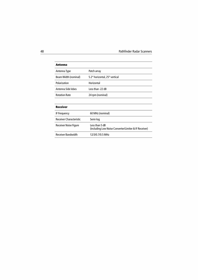
48 Pathfinder Radar Scanners
Antenna
Antenna Type Patch array
Beam Width (nominal) 5.2° horizontal, 25° vertical
Polarization Horizontal
Antenna Side lobes Less than -22 dB
Rotation Rate 24 rpm (nominal)
Receiver
IF Frequency 60 MHz (nominal)
Receiver Characteristic Semi-log
Receiver Noise Figure Less than 5 dB (including Low Noise Converter/Limiter & IF Receiver)
Receiver Bandwidth 12/3/0.7/0.5 MHz
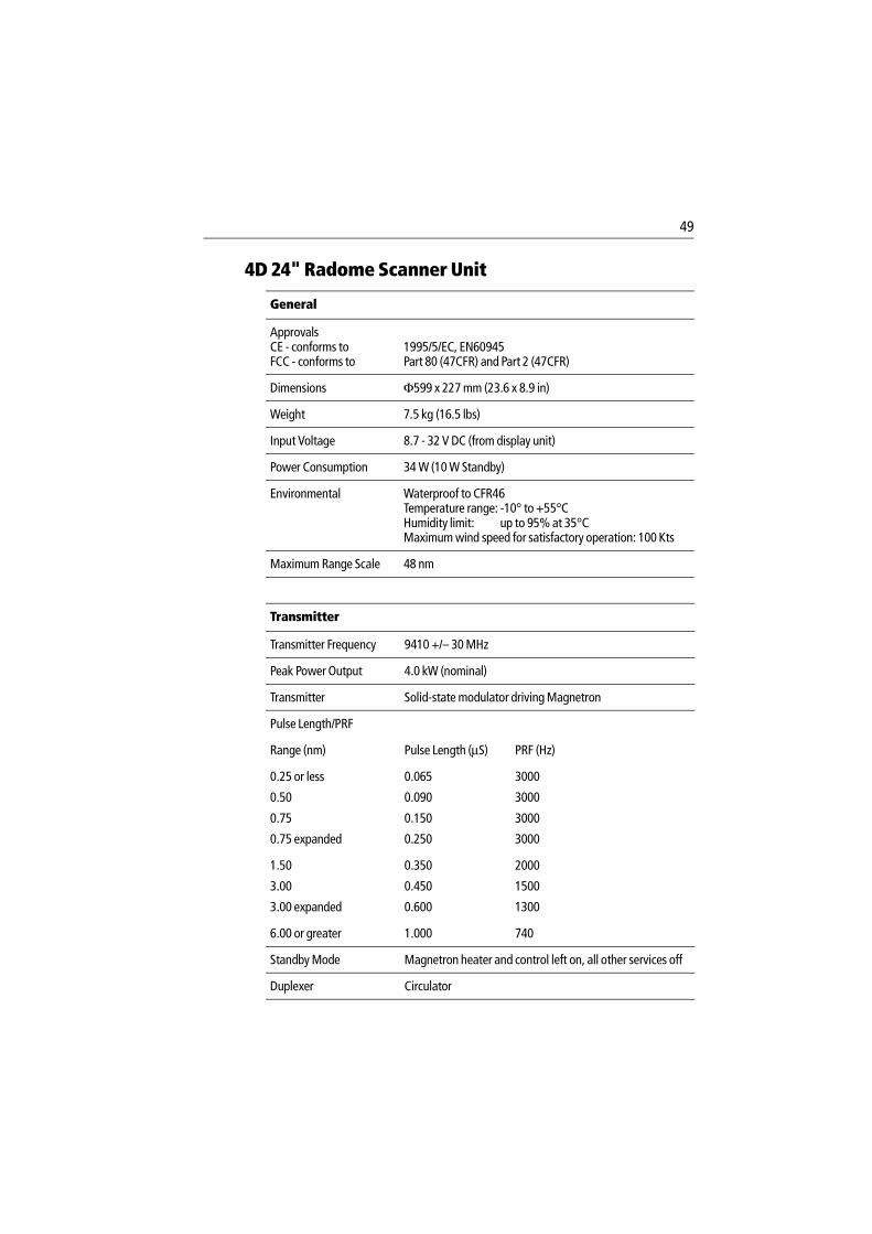
49
4D 24" Radome Scanner Unit
General
ApprovalsCE - conforms toFCC - conforms to
1995/5/EC, EN60945Part 80 (47CFR) and Part 2 (47CFR)
Dimensions Φ599 x 227 mm (23.6 x 8.9 in)
Weight 7.5 kg (16.5 lbs)
Input Voltage 8.7 - 32 V DC (from display unit)
Power Consumption 34 W (10 W Standby)
Environmental Waterproof to CFR46Temperature range: -10° to +55°CHumidity limit: up to 95% at 35°C Maximum wind speed for satisfactory operation: 100 Kts
Maximum Range Scale 48 nm
Transmitter
Transmitter Frequency 9410 +/– 30 MHz
Peak Power Output 4.0 kW (nominal)
Transmitter Solid-state modulator driving Magnetron
Pulse Length/PRF
Range (nm) Pulse Length (µS) PRF (Hz)
0.25 or less 0.065 3000
0.50 0.090 3000
0.75 0.150 3000
0.75 expanded 0.250 3000
1.50 0.350 2000
3.00 0.450 1500
3.00 expanded 0.600 1300
6.00 or greater 1.000 740
Standby Mode Magnetron heater and control left on, all other services off
Duplexer Circulator

50 Pathfinder Radar Scanners
Antenna
Antenna Type Patch array
Beam Width (nominal) 3.9° horizontal, 25° vertical
Polarization Horizontal
Antenna Side lobes Less than -22dB
Rotation Rate 24 rpm (nominal)
Receiver
IF Frequency 60 MHz (nominal)
Receiver Characteristic Semi-log
Receiver Noise Figure Less than 5 dB(including Low Noise Converter/Limiter & IF Receiver)
Receiver Bandwidth 12/3/0.7/0.5 MHz
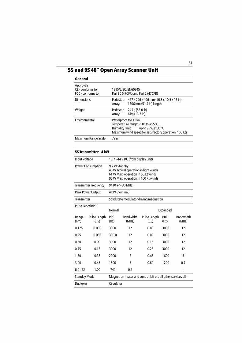
51
5S and 9S 48" Open Array Scanner Unit
General
ApprovalsCE - conforms toFCC - conforms to
1995/5/EC, EN60945Part 80 (47CFR) and Part 2 (47CFR)
Dimensions Pedestal: 427 x 296 x 406 mm (16.8 x 10.5 x 16 in)Array: 1306 mm (51.4 in) length
Weight Pedestal: 24 kg (53.0 lb)Array: 6 kg (13.2 lb)
Environmental Waterproof to CFR46Temperature range: -10° to +55°CHumidity limit: up to 95% at 35°CMaximum wind speed for satisfactory operation: 100 Kts
Maximum Range Scale 72 nm
5S Transmitter - 4 kW
Input Voltage 10.7 - 44 V DC (from display unit)
Power Consumption 9.2 W Standby46 W Typical operation in light winds61 W Max. operation in 50 Kt winds96 W Max. operation in 100 Kt winds
Transmitter Frequency 9410 +/– 30 MHz
Peak Power Output 4 kW (nominal)
Transmitter Solid state modulator driving magnetron
Pulse Length/PRFNormal
Expanded
Range(nm)
Pulse Length(µS)
PRF(Hz)
Bandwidth(MHz)
Pulse Length(µS)
PRF(Hz)
Bandwidth(MHz)
0.125 0.065 3000 12 0.09 3000 12
0.25 0.065 300 0 12 0.09 3000 12
0.50 0.09 3000 12 0.15 3000 12
0.75 0.15 3000 12 0.25 3000 12
1.50 0.35 2000 3 0.45 1600 3
3.00 0.45 1600 3 0.60 1200 0.7
6.0 - 72 1.00 740 0.5 - - -
Standby Mode Magnetron heater and control left on, all other services off
Duplexer Circulator
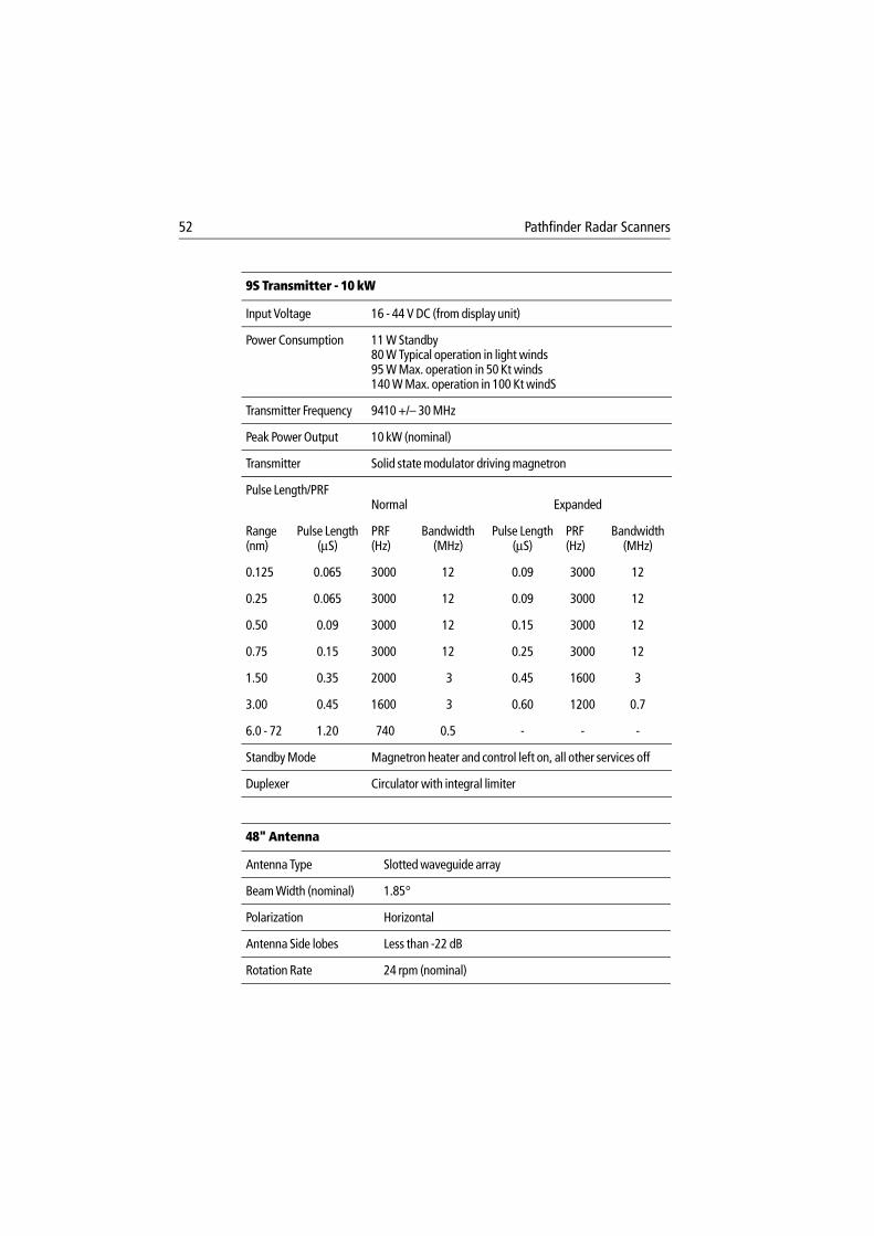
52 Pathfinder Radar Scanners
9S Transmitter - 10 kW
Input Voltage 16 - 44 V DC (from display unit)
Power Consumption 11 W Standby80 W Typical operation in light winds95 W Max. operation in 50 Kt winds140 W Max. operation in 100 Kt windS
Transmitter Frequency 9410 +/– 30 MHz
Peak Power Output 10 kW (nominal)
Transmitter Solid state modulator driving magnetron
Pulse Length/PRF Normal Expanded
Range(nm)
Pulse Length(µS)
PRF(Hz)
Bandwidth(MHz)
Pulse Length(µS)
PRF(Hz)
Bandwidth(MHz)
0.125 0.065 3000 12 0.09 3000 12
0.25 0.065 3000 12 0.09 3000 12
0.50 0.09 3000 12 0.15 3000 12
0.75 0.15 3000 12 0.25 3000 12
1.50 0.35 2000 3 0.45 1600 3
3.00 0.45 1600 3 0.60 1200 0.7
6.0 - 72 1.20 740 0.5 - - -
Standby Mode Magnetron heater and control left on, all other services off
Duplexer Circulator with integral limiter
48" Antenna
Antenna Type Slotted waveguide array
Beam Width (nominal) 1.85°
Polarization Horizontal
Antenna Side lobes Less than -22 dB
Rotation Rate 24 rpm (nominal)
53
Note: If the scanner is bought for use with an existing display, contact your dealer/service agent for the latest display software to ensure you can use all the open array scanner fea-tures.
Receiver
IF Frequency 60 MHz (nominal)
Receiver Characteristic Semi-log
Receiver Noise Figure Less than 5 dB (including Low Noise Converter/Limiter & IF Receiver)
Receiver Bandwidth 12/3/0.7/0.5 MHz
54 Pathfinder Radar Scanners
7S and 11S 72" Open Array Scanner Unit
General
ApprovalsCE - conforms toFCC - conforms to
1995/5/EC, EN60945Part 80 (47CFR) and Part 2 (47CFR)
Dimensions Pedestal: 427 x 296 x 406 mm (16.8 x 10.5 x 16 in)Array: 1918 mm (75.5 in) length
Weight Pedestal: 24 kg (53.0 lb)Array: 9.4 kg (20.7 lb)
Environmental Waterproof to CFR46Temperature range: -10° to +55°CHumidity limit: up to 95% at 35°C Maximum wind speed for satisfactory operation: 100 Kts
Maximum Range Scale 72 nm
7S Transmitter - 4 kW
Input Voltage 10.7 - 44 V DC (from display unit)
Power Consumption 9.2 W Standby46 W Typical operation in light winds83W Max. operation in 50 Kt winds135W Max. operation in 100 Kt winds (min. input voltage 11.4 V for winds >75kt)
Transmitter Frequency 9410 +/– 30 MHz
Peak Power Output 4 kW (nominal)
Transmitter Solid state modulator driving magnetron
Pulse Length/PRFNormal Expanded
Range(nm)
Pulse Length(µS)
PRF(Hz)
Bandwidth(MHz)
Pulse Length(µS)
PRF(Hz)
Bandwidth(MHz)
0.125 0.065 3000 12 0.09 3000 12
0.25 0.065 300 0 12 0.09 3000 12
0.50 0.09 3000 12 0.15 3000 12
0.75 0.15 3000 12 0.25 3000 12
1.50 0.35 2000 3 0.45 1600 3
3.00 0.45 1600 3 0.60 1200 0.7
6.0 - 72 1.00 740 0.5 - - -
Standby Mode Magnetron heater and control left on, all other services off
Duplexer Circulator
55
11S Transmitter - 10 kW
Input Voltage 20 - 44 V DC (from display unit)
Power Consumption 11 W Standby80 W Typical operation in light winds117 W Max. operation in 50 Kt winds179 W Max. operation in 100 Kt windS
Transmitter Frequency 9410 +/– 30 MHz
Peak Power Output 10 kW (nominal)
Transmitter Solid state modulator driving magnetron
Pulse Length/PRFNormal
Expanded
Range(nm)
Pulse Length(µS)
PRF(Hz)
Bandwidth(MHz)
Pulse Length(µS)
PRF(Hz)
Bandwidth(MHz)
0.125 0.065 3000 12 0.09 3000 12
0.25 0.065 3000 12 0.09 3000 12
0.50 0.09 3000 12 0.15 3000 12
0.75 0.15 3000 12 0.25 3000 12
1.50 0.35 2000 3 0.45 1600 3
3.00 0.45 1600 3 0.60 1200 0.7
6.0 - 72 1.20 740 0.5 - - -
Standby Mode Magnetron heater and control left on, all other services off
Duplexer Circulator with integral limiter
72" Antenna
Antenna Type Slotted waveguide array
Beam Width (nominal) 1.15°
Polarization Horizontal
Antenna Side lobes Less than -25 dB
Rotation Rate 24 rpm (nominal)

56 Pathfinder Radar Scanners
Note: If the scanner is bought for use with an existing display, contact your dealer/service agent for the latest display software to ensure you can use all the open array scanner fea-tures.
Receiver
IF Frequency 60 MHz (nominal)
Receiver Characteristic Semi-log
Receiver Noise Figure Less than 5 dB (including Low Noise Converter/Limiter & IF Receiver)
Receiver Bandwidth 12/3/0.7/0.5 MHz
Index 57
Index
AAlignment
Bearing 40Position of 72" Open Array Scanner 40
BBearing Alignment 40
CCable Requirements 11Cable Runs 13Cables 17
Extension 4Open Array 17, 19, 20Radome 14, 16, 18
Inter-unit 4Open Array 17, 31Radome 14, 24
Open Array with C-Series 21Open Array with Pathfinder 17Part Numbers 4Pedestal Adaptor 4, 21Power
Open Array 18Radome 15
Rejoining 13Requirements 11Split Pedestal 4, 21
ConnectionsOpen Array Scanner 30Power 22Radome Scanner 24
DDisplay Timing Adjustment 40
EElectromagnetic Energy i, 40EMC iv
Conformance ivInstallation Guidelines 2
Extension Cables 4Open Array 17, 19Radome 14, 16, 18
GGrounding the System 22
HHelp from Raymarine
Europe 44US 43Worldwide 45
High Voltage i
IInter-unit Cable 4
Open Array 17, 31Radome 14, 24
LLocation 5
MMaintenance and Problem Solving 39Mounting
Open Array Scanner 29Radome Scanner 23Scanner
on Power Boats 9on Sailboats 9
NNavigation Aid ii
OOpen Array Scanner
48" iii, 1, 5172" iii, 1, 5472" - Position Alignment 40Connections 30Mounting 29Pedestal 34
PParts List 3Pedestal - Open Array Scanner 34Pedestal Adaptor Cable 4, 21Power
CablesOpen Array 18Radome 15
Connections 22Problem Solving 42
58 Pathfinder Radar Scanners
RRadar System
Grounding 22Typical System Diagram 1
Radome Scanner18" iii, 1, 4724" iii, 1, 49Connections 24Mounting 23
Rejoining Cables 13Routine Checks 41
SSafety
- and Servicing 41Electromagnetic Energy iHigh Voltage iNavigation Aid ii
Scanner iLocation 5Mounting
on Power Boats 9on Sailboats 9
Scanner - See also Open Array Scanner, Radome Scanner iServicing and Safety 41Set Up 39Specification
18" Radome Scanner 4724" Radome Scanner 4948" Open Array Scanner 5172" Open Array Scanner 54
Split Pedestal Cable 4, 21System Check 39
TTiming Adjustment 40Transmission Check 40
WWarranty iv

25
Limited Warranty Certificate
In order to ensure that the equipment continues to operate efficiently and reliably, we recommend that before using the product, the customer carefully read the Owner’s handbook and follow the advice on the safe and correct operation and use of the product. We recommend that Raymarine equipment, be installed by an approved Raymarine installer.
Warranty Registration
Please register your warranty on-line at www.raymarine.com to ensure smooth warranty processing.
1. Limited Product Warranty
Raymarine warrants that all of its product, in the course of normal use, will be free from defects in material and workmanship for a period of 2 years (24 months) from date of sale to the original end user, subject to the limitations set forth in this warranty. The Raymarine warranty covers the parts and labor associated with a warranty repair as described above, provided that the product is returned to Raymarine or one of its approved agents in accordance with Section 3 hereof.
2. On-board Warranty
Raymarine will authorize on-board warranty service by the nearest Raymarine approved service agent, subject to maximum mileage and travel times refereed to in Section 4, on products where proof of installation, or commission by Raymarine certified installers is shown.
The warranty provides for on-board repair or exchange of the product, by Raymarine or its approved service agents, for a period of 1 year (12 months), subject to the limits contained in this warranty.
In the case of a product installed by a Raymarine certified installer or boat-builder, the warranty commences on date of installation or from the date of sale of the boat to the original end user, subject to the limitations set forth in this warranty.
3. Obtaining Warranty Service
In the event of warranty service being necessary, the customer should contact Raymarine Technical Support or the nearest Raymarine approved service agent, the contact details of whom are available on the Internet at www.raymarine.com or directly from Raymarine.
In cases where the customer is requesting a warranty service on a Raymarine product under this warranty, and where a Raymarine certified installer has not installed the product; i.e. Limited Product Warranty, the affected product must be returned to the customers local Raymarine approved service agent or direct to Raymarine with a copy of either:
(a) Proof of purchase showing the date of purchase, the name of the seller and the serial number of the affected product; or

26 Limited Warranty Certificate
(b) A warranty card completed by the seller of the product containing the information required in (a) above.
In cases where the customer is making a warranty claim on a Raymarine product under this warranty, and where the product has been installed by a Raymarine certified installer, (boat-builder, installer dealer etc.) i.e. On-board Warranty, the nearest Raymarine approved service agent should be contacted and on-board service requested (which will be subject to the mileage and travel time limits referred to in Section 4 hereof). Before the installed warranty service is performed, the customer must have available, either:
(a) Proof of purchase showing the date of purchase, the name of the seller and the serial number of the affected product and proof of installation by a Raymarine certified installer; or
(b) A warranty card completed by the seller of the product containing the information required in (a) above.
Subject to the limitations and other provisions set forth in this warranty, the product will be either repaired or replaced by Raymarine within a reasonable period of time and at no further cost to the customer. the determination of whether to repair or replace a product shall be at the sole discretion of Raymarine, and shall be the sole remedy of the customer under this warranty.
4. Warranty Limitations
Raymarine warranty does not apply to equipment that has been subjected to accident, abuse or mis-use, shipping damage, alterations, corrosion, incorrect and/or non-authorized service, or to a product on which the serial number has been altered, mutilated or removed.
Raymarine assumes no responsibility for damage incurred during installation or as a result of incorrect installation.
This warranty does not cover routine system checkouts, alignment or calibration, sea-trials or commissioning, unless required by replacement of part(s) in the area being aligned.
Magnetrons, cathode ray tubes (CRTs), thin film transistor (TFT) liquid crystal displays (LCDs) and cold cathode fluorescent lamps (CCFLs, hailer horns and transducers are warranted for 1 year (12 months) from date of sale.
Raymarine is not liable and assumes no responsibility for damage caused by or to other equipment, systems or components occasioned by improper or unauthorized connection, or use of the product.
Consumable items, including, but not limited to; fuses, batteries, drive belts, radar mixer diodes, snap-in impeller carriers, impellers, impeller bearings, and impeller shafts are specifically excluded from this warranty.
Overtime/premium labor portion of services outside of normal working hours is not covered by this warranty.
If repairs are necessary under the warranty, the affected product must be forwarded to a Raymarine facility or an approved Raymarine service agent, at the owners expense in a manner set forth in Section 3 hereof.

27
This warranty does not cover any differences in material, coloring or size between those alluded to in corporate advertising, literature or published on the Internet, which is not specifically objected to at the time of delivery.
Travel costs other than those qualifying for on-board warranty (up to a maximum of 100 auto miles, tolls and two (2) hours travel time), are specifically excluded from the warranty and shall be the responsibility of the customer. Costs, which are excluded from the coverage of this warranty, include, but are not limited to: taxi fares, launch fees, aircraft rental, subsistence, customs, shipping and communication charges etc.
To the extent consistent with State and Federal Law:
The foregoing warranty is Raymarines sole warranty and is applicable only to products sold as new. The remedies provided herein are in lieu of:
any and all other remedies and warranties, whether express or implied including but not limited to, any implied warranty of merchantability or fitness for a particular purpose.
all obligations of Raymarine for damages including, but not limited to accidental, consequential or special damages (including punitive or multiple), or any financial loss, loss of profit, business, contracts, opportunity, goodwill or other similar loss arising out of or in connection with the purchase, use or performance of any Raymarine product, even if Raymarine has been advised of the possibility of such damages, and no case shall exceed the cost of the product. The remedies to the customer are herein exclusive.
Some jurisdictions do not allow exclusion or limitation of incidental or consequential damages, so the above limitations or exclusions may not apply to you. This warranty gives you specific legal rights and you may also have other rights, which vary from jurisdiction to jurisdiction.
The Raymarine warranty terms and conditions as described herein do not affect the customers statutory rights and comply with EU Directive 1999/44/EC.
Raymarine is the sole author of this policy and makes no further warranties, express or implied unless a separate, specific warranty has been written and provided to the customer. This warranty supersedes and replaces all previous warranties.
All Raymarine products are merely aids to navigation. It is the responsibility of the user to exercise discretion and proper navigational skill, independent of any Raymarine equipment.
Document No: 84064_11
Date:February 2004
28 Limited Warranty Certificate
Factory Service Centers
United States of America UK, Europe, Middle East, Far East
Raymarine Inc22 Cotton Road, Unit D,Nashua, NH03063-4219, USA
Telephone: +1 603 881 5200Fax: +1 603 864 4756www.raymarine.com
Raymarine LtdAnchorage Park, PortsmouthPO3 5TD, England
Telephone: +44 (0) 23 9269 3611Fax: + 44 (0) 23 9269 4642www.raymarine.com
Sales & Order ServicesTelephone: + 1 800 539 5539 Ext. 2333 or
+1 603 881 5200 Ext 2333
Customer SupportTelephone: + 44 (0) 23 9271 4713Fax: + 44 (0) 23 9266 1228www.raymarine.com
Technical SupportTelephone: +1 800 539 5539 Ext: 2444 or
+1 603 881 5200 Ext:2444www.raymarine.com
Product Repair CentreTelephone: +1 800 539 5539 Ext:2218
Stick barcode label here
Purchased from Purchase date
Dealer address
Installed by Installation date
Commissioned by
Commissioning date
Owners name
Mailing address
This portion should be completed and retained by the OwnerWHY NOT SAVE TIME AND EFFORT & REGISTER YOUR PRODUCT WARRANTY ON-LINE at
www.raymarine .come