Embed Size (px)
Citation preview

Pathways for Cabling Infrastructure
David Landphair, RCDD
• Regional Sales Manager - NA CADDY Data & Telecom

Today’s Content
How to design and install proper pathway systems
for cost-effectiveness, code & standards compliance
and long-term integrity of horizontal and vertical
structured cabling.
Continuous pathway alternatives such as non-
continuous supports (such as J-Hooks), cable
pulleys, better wall boxes, and other technologies
will be discussed for overhead, wall, and under floor
applications.

Industry Changes
• The industry has changed much since the 80’s break up of AT&T and the RBOC’s
• Cabling has changed with the times
– station wire for telephones
– IBM System 3270’s, IBM System 34,36,38, RG62A/U coax, Twin-Ax, Wang-Net – Belden 9269, 9207, 9555
– Nevada-Western, balun’s for coax and twinax …
– CAT3, CAT4 (for a couple of weeks), CAT5, CAT5e, CAT5E, CAT6, Augmented CAT6, CAT6A, CAT7, CAT7A, proposed CAT8 … ?
– Fiber has gone from 50/125 to 62.5/125 back to 50/125

Pathway Changes
• From everything in conduit to …
• Open Architecture
– Cable Tray
– Non-Continuous Supports
– Laying cable on top of drop ceilings, beams, red iron, etc.

Infrastructure
• Cabling infrastructure is being pushed to its’ limits and the potential weakest link is not always the cable, connectivity, or patch cords but the pathways and how the cable is physically being installed
• This is true for both copper and fiber systems

Wide Based vs. Narrow Based Supports
• Prior to the 90’s, the primary non-continuous pathway was the bridle ring, cable tie, wire, string, ceiling grid supports, beams, electrician’s tape – narrow based products
• As cables increased in performance & speed, a wide-based non-continuous support was needed to provide the required bend radius support and to better distribute the load of the cable bundle
– The “J-hook” was introduced by ERICO CADDY in 1995 to meet the needs of the fast changing industry

As Speeds Increase, Cable Designs Change
• Diameter Changes – CAT3 to CAT5: .187 to .19
– CAT5 to CAT5E: .19 to .20
– CAT5E to CAT6: .20 to .23
– When Augmented CAT6 was first introduced, the cable was as large as .5”
– CAT6A is now .30-.32 or less due to the engineering efforts of the cable manufacturers
• Weight Changes – Weights of cable per 1000/ft are also changing from 20 lbs
for CAT5e to 50 lbs for CAT6A
• What will be the requirements of the next generation of cable – copper or fiber?

Types of Wide Based Supports
• Various manufacturers of metal and plastic supports

The Need For Wide Based Supports
• TIA 568-C
– 5.3.2.1 Copper Cable - Cable bend radius may
vary depending on the cable condition during
installation (tensile load) and after installation
when the cable is at rest (no-load). The minimum
inside bend radius, under no-load or load, for 4-
pair balanced twisted-pair cable shall be four-
times the cable diameter. For example, a cable
diameter of 9 mm (0.354 in) requires a minimum
bend radius of 36 mm (1.5 in). The minimum bend
radius, under no-load or load, for multi-pair cable shall follow the manufacturer’s guidelines.

The Need For Wide Based Supports
• TIA 568-C
– 5.4.1 Fiber Cable
• 2-4 strand inside plant fiber 2”/1” – load/no load
• Most other fiber is 20 times O.D. under load
and 10 times O.D. no load
• New fiber (bend insensitive) designs have
significantly decreased these requirements and
the manufacturers guidelines for installation
should be followed.

Bend Radius Support
Cable sag support in horizontal runs Bend radius support for direction
changes vertically and around
corners

Actual Bend Radius Requirements
Cable Type Overall Diameter Bend Radius Requirement
CAT5e Plenum 0.182” – 0.207” 0.75” – 0.83”
CAT6 Plenum 0.22” 0.88”
CAT6A 0.30” 1.20”
CAT7*/CAT6A* Plenum 0.30” – 0.32” 1.20” – 1.28”
CAT7A* Plenum 0.31” – 0.32” 1.24” – 1.28”
* Shielded cable – either overall shielded or individual pair shielded

Examples of Quality Installations

Wide Based Support Issues
• Bend radius support – does the product really support the cable for sag between supports and for direction changes – vertical to horizontal or around corners

Pathway Standard – TIA 569-C
• TIA 569-C.9.7
– Non-continuous supports shall be located at intervals not to exceed 1.5 m (5 ft.). Non-continuous supports shall be selected to accommodate the immediate and anticipated quantity, weight, and performance requirements of cables.
• It is recommended not to make long runs exactly 5 ft apart due to “harmonics” issues per cable manufacturers

Other Standards Based Issues
• TIA 568-C.5.3.1 – maximum pulling tension – The pulling tension for a 4-pair
balanced twisted-pair cable shall not exceed 110 N (25 lbf) during installation. For multipair cable, manufacturer’s pulling tension guidelines shall be followed.
• It is a best practice to keep the sag between supports at a maximum of 300 mm (12”)

NEC Requirements
• Non-continuous pathways do not need to be bonded together or grounded (2011 NEC 250.92.A.1)
• Non-continuous pathways must conform to the requirements of NEC 300.11 above the ceiling grid
– Electrical/communication/security wiring methods in a suspended ceiling must be installed on independent support wires/rods
– All suspended ceiling applications must have visually distinguishable independent support wires (2011 NEC)
– Wire must be affixed at both ends to minimize movement

Installation Safety
• Safety is an important
factor during the installation process
• Use cost effective cable
pulleys manufactured by
several companies to
minimize the pulling
tension on cables and
maintain the maximum 25
lbf tension
• Reusable pulleys from
$18 to $100

Why Use Certified Products?
Certifications = Confidence in Safe Products

Verified Load Ratings = Safety
• Certification with independent agencies (such as UL, Intertek, etc.) demonstrates credibility of load capacity, including assemblies
• UL 2239 (CAN/CSA C22.2 No. 18.4) and UL 1565 (CSA C22.2 No. 18.5) are two standards that non-continuous support manufacturers use, but they are not identical in terms of load test requirements
• Listing to UL 2239 ensures a larger safety factor requiring a test load of 3x load rating – listed for both flexible and non-flexible cable, conduit, and tubing
• UL 1565 allows a test load at the load rating
• Listings to UL 2239 and UL 1565 are not equal!

Why Are Base Materials Important?
• Critical to use approved pathways and supports for the safety of firemen/emergency responders and employees in case of an event – Recent article about a fire in London April 6, 2010, which stated that
two firemen died due in part to being tangled in cabling that had fallen from the ceiling – Shirley Towers event
(http://www.bbc.co.uk/news/uk-england-hampshire-22126431)
• In Nova Scotia, the provincial building code requires every 3rd non-continuous support must be metal
• European test standards and building practices have an increasing focus on fire ratings of cable supports. Several manufacturers have performed tests to DIN 4102-12 (fire resistance of electrical cable systems required to maintain circuit integrity – Requirements & testing)

Let’s Go Racing – NASCAR Style

Performance Questions
• J-hooks can provide equal or better performance characteristics vs. basket tray – BICSI Vegas 2007 presentation by ERICO stated
that CAT6 cable in a 6 around 1 worst case scenario installed in a 90 meter run at transmission speeds up to 10Gb and frequencies up to 500 MHz performed slightly better than basket tray and ladder
– The cable separation between supports provides the space between cables necessary to minimize Alien Cross-Talk issues

Large Capacity Options
• J-hook “trees” offer capacity and cable management
– Many J-hook size options
– Cable segmentation for data, security/fire, fiber, nurse call, A/V – colored J-hook options
– Flexibility
– Smaller cable bundles – less chance for overloading pathways
– Ease of removing “abandoned” cable per the NEC

TIA 1179 & Colors
• Section 10.3 under Administration
– “Accordingly, the use of colored cables, colored jacks or keyed connectivity should be considered for those networks in order to maintain segregation of the networks and assist in the administration.”
• Colored pathways are not currently a requirement per the codes or standards but many hospitals and similar organizations are using colors to segment their cable disciplines

Other Considerations
• Compared to conventional wire basket tray – Up to 88% less steel used
– Up to 60 – 75% labor installation cost savings
– Performance is comparable to tray systems
– Grounding & bonding are not required for non-continuous metal pathways
– Easier to reconfigure for MAC work

Cable Tray Support Options
• Traditional threaded rod, beam clamps, strut for trapeze supports, standard “nuts”
• “Aircraft type cable” UL listed systems that several manufacturers offer in different configurations for time savings installations
• New threaded beam clamps, strut/channel nuts, ceiling anchors available in the market for time saving installations
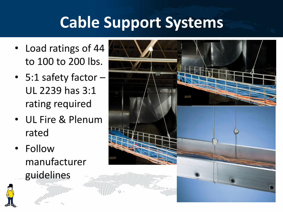
Cable Support Systems
• Load ratings of 44 to 100 to 200 lbs.
• 5:1 safety factor – UL 2239 has 3:1 rating required
• UL Fire & Plenum rated
• Follow manufacturer guidelines

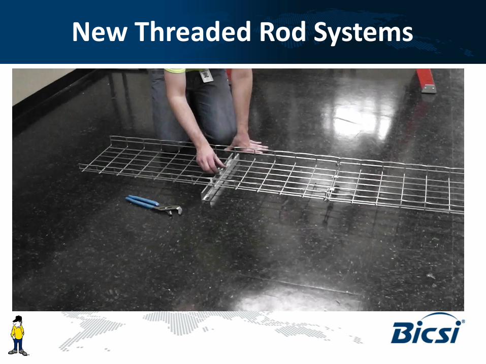
New Threaded Rod Systems
• Push in system vs. threading into the following parts
– Beam Clamp – 500 lb.
– Strut/Channel Nut – 750 lb.
– Ceiling Anchor – 660 lb.
– “Split Nut” – ¼”, 3/8”, ½”
– Telescoping “strut” bracket”
New Threaded Rod Systems

Wall Installation Issues
• Many facilities are being designed with conduit stubs in the walls
– The problem being with multiple CAT6/6A or a combination of copper and fiber, the standard 4 square & 4-11/16 boxes are not large enough to maintain the minimum bend radius and separation of the cables

Wall Installation Issues
– Traditional low voltage new construction mounting brackets do not allow for attaching the conduit stub to the bracket
– Consideration needs to be given to determine if the location is a fire-rated wall or not
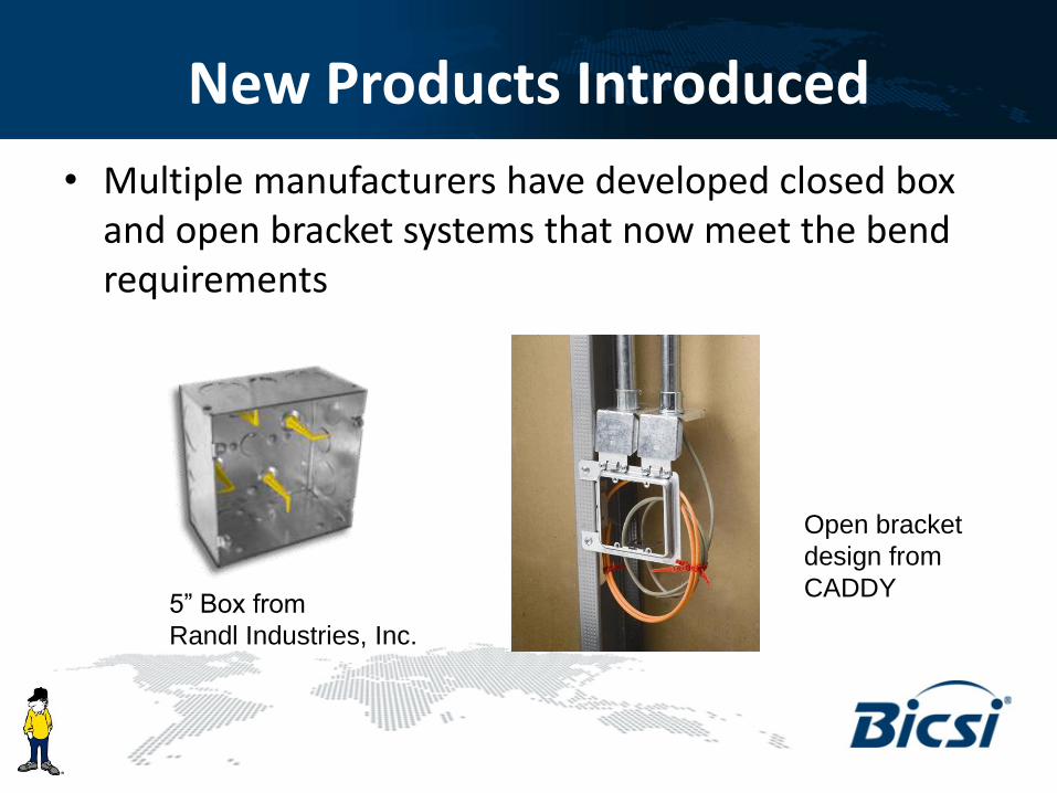
New Products Introduced
• Multiple manufacturers have developed closed box and open bracket systems that now meet the bend requirements
5” Box from
Randl Industries, Inc.
Open bracket
design from
CADDY

Raised Floor Applications
• History – Cabling over time has gone from above the cabinets to below the raised floors and are now going back to above the cabinets
• Reason – Better air flow through the raised floor plenum
• Large capacity cable pathways were creating air dams which affected the HVAC performance by as much as 30%
• Are there options for small cable supports for below the floor?

Raised Floor Solutions

Conclusions
• Cabling Infrastructure has changed significantly. Is your infrastructure ready for future changes?
• TIA-568-C requires bend radius of 4x cable diameter and Category cable diameters are increasing
• Certified products are recommended. Understand what the UL Listings mean.
• Properly designed J-Hook supports provide equal or better performance characteristics compared to basket tray and are available in a large number of configurations
• New product designs are available for wall and raised floor applications to maintain cable performance

Questions?

THANK YOU!