Embed Size (px)
Citation preview

Idaho National Engineering and Environmental Laboratory
Prismatic Core VHTR Analysis usingRELAP5-3D/ATHENAPaul D. Bayless
August 28, 2003

Idaho National Engineering and Environmental Laboratory
2
Outline• Analysis objectives• VHTR description• RELAP5-3D/ATHENA input model description• Benchmarking results• Scoping calculation results• Code implications

Idaho National Engineering and Environmental Laboratory
3
VHTR Analysis Objectives• Near term
– develop a representative model of the reactor vessel
– perform scoping analyses to establish basic operating parameters
• Longer term– develop an independent analysis capability for
DOE to use during the plant design and licensing phases

Idaho National Engineering and Environmental Laboratory
4
What is the VHTR?• One of the six selected Generation IV reactor
concepts• Helium cooled, graphite moderated, thermal neutron
spectrum reactor• Passively safe• Reactor vessel coolant outlet temperature of 1000°C• Will be used for generating both electricity and
hydrogen

Idaho National Engineering and Environmental Laboratory
5
VHTR Plant Schematic

Idaho National Engineering and Environmental Laboratory
6
Reactor Vessel Cutaway
Control Rod Drive Assembly
Refueling Stand Pipe
Control Rod Guide tubes
Cold leg Core Coolant Upper Plenum
Central Reflector Graphite
Annular shaped Active Core
Outer Side Reflector Graphite
Core Exit Hot Gas Plenum
Graphite Core Support Columns
Reactor Vessel
Upper Plenum Shroud
Shutdown Cooling System Module Hot Duct
Insulation Module
Cross Vessel Nipple
Hot Duct Structural Element
Metallic Core Support Structure
Core Inlet Flow
Core Outlet Flow
Insulation Layer for Metallic Core Support Plate
Upper Core Restraint Structure
Control Rods
7m(23 ft)
23.7m(78ft)
2.2m(7ft)
8.2m(27ft) Dia Vessel Flange

Idaho National Engineering and Environmental Laboratory
7
Reactor Vessel Cross Section

Idaho National Engineering and Environmental Laboratory
8
Fuel Element Cross Section
Fuel rods
Coolant channels
Block handling hole
Location for burnablepoison rod

Idaho National Engineering and Environmental Laboratory
9
Model Overview• A simplified RELAP5-3D/ATHENA system model is
being used, in which the balance of plant has been neglected thus far.
• Reactor vessel with helium coolant• Reactor cavity with water coolant and dry
noncondensible air• Reactor cavity cooling system with water coolant and
dry noncondensible air

Idaho National Engineering and Environmental Laboratory
10
Reactor Vessel Model• Coolant active and stagnant volumes• Structures in the core region
– inner and outer reflectors– upper and lower reflectors– core barrel– upper plenum shield– reactor vessel wall and upper head
• Structures below the core are being ignored• Boundary conditions
– coolant inlet temperature– coolant outlet pressure– inlet flow rate adjusted during steady state to provide desired outlet
temperature

Idaho National Engineering and Environmental Laboratory
11
VHTR Vessel Hydraulic Nodalization
120
130 140
152
110
170100 105
160
154 156

Idaho National Engineering and Environmental Laboratory
12
Ex-vessel Model• Containment air volume• Reactor cavity cooling system (RCCS)
– Inlet plenum/downcomer piping– Lower distribution plenum– Riser/outlet plenum– Riser, downcomer, and outer metal walls
• Containment concrete wall and surrounding soil (behind RCCS downcomer)
• Other structures/walls neglected

Idaho National Engineering and Environmental Laboratory
13
VHTR Reactor Cavity Nodalization
905 975 955
965
900 900
970 960
950980

Idaho National Engineering and Environmental Laboratory
14
Heat Transfer Modeling with Original RCCS Model
Core
Inner reflector
conductionconduction
Outer reflector
Reactor vessel
RCCS inner wall
RCCS interior wall
Containment wall
radiation
radiation
radiation
radiation
convection
convection
convection
convection
He coolant
Axial conduction incore and reflectors
convection

Idaho National Engineering and Environmental Laboratory
15
Heat Transfer Modeling with Revised RCCS Model
Core
Inner reflector
conductionconduction
Outer reflector
Reactor vessel
RCCS riser wall RCCS downcomer wall
Containment wall
radiation
radiation
radiation
convection,radiation
convection
convection
convection
He coolant
Axial conduction incore and reflectors
convection

Idaho National Engineering and Environmental Laboratory
16
Reactor Cavity Radiation ModeledRisers DowncomerReactor Vessel

Idaho National Engineering and Environmental Laboratory
17
GT-MHR Benchmarking• The model is being benchmarked against
calculations performed for the gas turbine-modular helium reactor (GT-MHR) by General Atomics.
• The steady state conditions for the VHTR model are adjusted to match the GT-MHR values (outlet temperature of 850°C, lower inlet temperature, higher flow rate).
• High and low pressure conduction cooldown (loss of forced flow) transients are modeled.
Idaho National Engineering and Environmental Laboratory
18
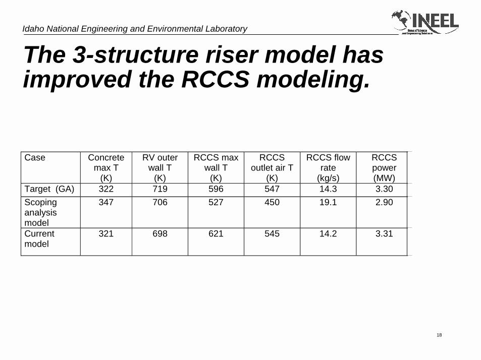
The 3-structure riser model has improved the RCCS modeling.
Case Concretemax T
(K)
RV outerwall T
(K)
RCCS maxwall T
(K)
RCCSoutlet air T
(K)
RCCS flowrate
(kg/s)
RCCSpower(MW)
Target (GA) 322 719 596 547 14.3 3.30Scopinganalysismodel
347 706 527 450 19.1 2.90
Currentmodel
321 698 621 545 14.2 3.31

Idaho National Engineering and Environmental Laboratory
19
Reduced decay heat has improved the transient benchmark.
Peak Fuel T(°C) Peak Vessel T (°C)CaseSteady HPCC LPCC Steady HPCC LPCC
Target (GA) 1238 1521 480 497 490
Scopinganalysis model
964 1504 1730 458 571 619
Lower decayheat model
971 1285 1514 455 471 520
Lower pressuretransient
1369 490

Idaho National Engineering and Environmental Laboratory
20
Scoping Transient Calculations• Objectives
– Provide feedback to the neutronics development on the effects of different core geometries
– Determine modeling sensitivities• High pressure conduction cooldown
– 60-s flow coastdown– Steady state operating pressure maintained
• Low pressure conduction cooldown– 10-s blowdown to atmospheric pressure– Air ingress precluded

Idaho National Engineering and Environmental Laboratory
21
Core Configuration Calculations
Peak Fuel T (°C) Peak Vessel T (°C)Fuelrings
Coreheight(blocks)
ReactorvesseldP (kPa)
Steady HPCC LPCC Steady HPCC LPCC
6-8 10 71 1119 1596 1807 551 597 643
6-8 11 75 1112 1535 1728 552 583 627
6-8 12 79 1107 1481 1659 552 572 611
5-7 11 92 1064 1707 1937 551 597 644
7-9 10 56 1113 1457 1622 552 595 634
7-9 12 62 1102 1360 1502 553 571 606

Idaho National Engineering and Environmental Laboratory
22
HPCC Peak Fuel Temperatures
0 20 40 60 80 100Time (h)
1000
1200
1400
1600
1800
2000
Tem
pera
ture
(C)
rings 6-8, 10 blocksrings 5-7, 11 blocksrings 6-8, 12 blocksrings 7-9, 10 blocksrings 7-9, 12 blocks

Idaho National Engineering and Environmental Laboratory
23
HPCC Peak Vessel Temperatures
0 20 40 60 80 100Time (h)
450
500
550
600
650
Tem
pera
ture
(C)
rings 6-8, 10 blocksrings 5-7, 11 blocksrings 6-8, 12 blocksrings 7-9, 10 blocksrings 7-9, 12 blocks

Idaho National Engineering and Environmental Laboratory
24
LPCC Peak Fuel Temperatures
0 20 40 60 80 100Time (h)
1000
1200
1400
1600
1800
2000
Tem
pera
ture
(C)
rings 6-8, 10 blocksrings 5-7, 11 blocksrings 6-8, 12 blocksrings 7-9, 10 blocksrings 7-9, 12 blocks
Idaho National Engineering and Environmental Laboratory
25
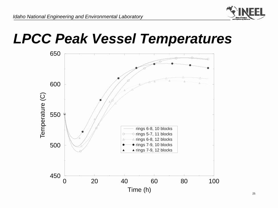
LPCC Peak Vessel Temperatures
0 20 40 60 80 100Time (h)
450
500
550
600
650
Tem
pera
ture
(C)
rings 6-8, 10 blocksrings 5-7, 11 blocksrings 6-8, 12 blocksrings 7-9, 10 blocksrings 7-9, 12 blocks

Idaho National Engineering and Environmental Laboratory
26
Modeling Sensitivity CalculationsPeak Fuel T (°C) Peak Vessel T (°C)
Case
ReactorvesseldP (kPa) Steady HPCC LPCC Steady HPCC LPCC
Base 71 1119 1596 1807 551 597 643Coolant channeldiameter reduced
79 1125 1628 1805 551 603 643
Flat axial and radialpower profiles
71 1094 1530 1684 551 585 618
Inner reflector heatcapacity increased
71 1119 1522 1694 551 583 622
0.1 mm He gaparound fuel
71 1133 1604 1813 551 598 645
Bypass channel ininner reflector
61 1170 1547 1749 551 587 626
Bypass channel inouter reflector
61 1180 1549 1784 550 582 634
Decay powerreduced 15%
71 1119 1483 1682 551 566 610
New RCCS model 71 1119 1574 1792 538 538 567
Idaho National Engineering and Environmental Laboratory
27
Code Results Summary• The code and model appear to be able to provide
reasonable results for the VHTR loss of flow transients.
• Thermal-hydraulic analyses indicate that changes in the core configuration may be helpful.
• Decay power and power distribution may have large impacts on the calculated transient fuel temperatures.
Idaho National Engineering and Environmental Laboratory
28
Code Improvement Possibilities• Axial conduction capability (outside of reflood) for the
heat structures• Air ingress modeling (molecular diffusion)• Extend/improve the decay heat model to account for
the epithermal neutron spectrum in gas reactors• Extend the material property definition options
available to the user• Allow SCDAP structures to participate in RELAP5
radiation/conduction enclosures