Embed Size (px)
Citation preview

Government of the People’s Republic of Bangladesh
Ministry of Communications Roads and Highways Department
PAVEMENT INVENTORY SURVEY MANUAL
MAY 2005

Ministry of Communication Road Inventory Roads and Highways Department Survey Manual
Page 2 (24)
TABLE OF CONTENTS
1. INTRODUCTION .............................................................................................. 3
2. ROAD NUMBERING....................................................................................... 4 2.1 OBJECTIVE ......................................................................................................4 2.2 PROCEDURE...................................................................................................4
2.2.1 Road Number ...............................................................................................4 2.2.2 Link Number.................................................................................................5
3. LOCATION REFERENCE POINTS.............................................................. 7 3.1 OBJECTIVE ......................................................................................................7 3.2 PROCEDURE...................................................................................................7
3.2.1 Description of Km posts.................................................................................9 4. CROSS SECTION INVENTORY.................................................................11
4.1 OBJECTIVE ....................................................................................................11 4.2 PROCEDURE.................................................................................................11
5. DRAINAGE INVENTORY.............................................................................13 5.1 OBJECTIVE ....................................................................................................13 5.2 PROCEDURE.................................................................................................13
6. PAVEMENT HISTORY..................................................................................14 6.1 OBJECTIVE ....................................................................................................14 6.2 PROCEDURE.................................................................................................14
APPENDICES Appendix 1 Location Reference Survey Form Appendix 2 Pavement Inventory Survey Form Appendix 3 Drainage Inventory Survey Form Appendix 4 History Inventory Survey Form

Ministry of Communication Road Inventory Roads and Highways Department Survey Manual
Page 3 (24)
1. INTRODUCTION Data collection is one task amongst many in the overall process of managing roads. It is an expensive and time-consuming task that needs to be properly planned and managed. It is essential that the data be: • Relevant to the decisions that must be taken • Affordable in terms of cost and human resources • Collectable i.e. physically feasible and reasonably convenient Above all, the data collection routines must be sustainable, i.e. ‘doable’ year after year. When a new road is to be included in RMMS is it important to focus on the specific data required for identification of the road in the network subsidiary the data for the Planning and Programming. This data will consist of: • Administrative data • Network referencing data • Inventory data • Road condition data • Traffic data Obtaining the first two of these are basically desk exercises and will only require a reconnaissance survey to confirm the road network to be included. It will be necessary to establish the network referencing data prior to all the others, as no other data can be stored in the database until the road has been defined and labelled. Inventory data does not change significantly with time and therefore does not have to be collected with regular intervals. It is anticipated that the collection could be a one-time activity for most inventory items with future changes derived from as-built drawings and contract construction and maintenance records at the time of completing project works. In Roads and Highways Department (RHD) the HDM Circle has the responsibility to produce a road gazette every year containing the relevant information which describes the entire RHD road network. The inventory of a road contains the following components: • Road and Link Numbering • Location Reference Point Survey • Cross Section Inventory Survey • Drainage Inventory Survey • Construction/Maintenance Inventory Survey This instruction manual has been prepared solely for use within RHD and describes the works that are being adopted for the Pavement Inventories. This guide is accessible on the RHD Intranet.

Ministry of Communication Road Inventory Roads and Highways Department Survey Manual
Page 4 (24)
2. ROAD NUMBERING 2.1 OBJECTIVE A standard system of road numbering was introduce under the Road Master Plan (RMP) Project and subsequently adopted by RHD. This numbering system is the primarily reference system for recording information about RHD road network. 2.2 PROCEDURE
2.2.1 Road Number Road occurrence is a set of sequentially connected Links. Each Road is identified by a unique alpha digit name called a Road Name. Road class, road function, road status and road name are constant from the start to the end of a Road. If any of these changes, then this is defined as another road. The Class of road is the hierarchy of roads by physical standard related to traffic flow. The Road Function is the allocation of a road by purpose as one of National, Regional or District Road. The Status of a road is the hierarchy of roads which are defined as of importance at the national level, the provincial level, or the district levels. The Road Name is the official name of the road as defined by the government office. Three types of RHD road are recognised: National Highways: National highways connect the capital with Divisional HQs or
sea ports or land ports. National highways connect the capital with international
borders. A National Highway must branch of from another National
Highway, National Highways cannot connect between Regional Highways or Zilla Roads.
N1 - N8 Major national routes. N101 - N809 National routes of lesser importance, where the first number is
the major national route and the second digit (chronological order) designates a serial number.
Regional Highways: Regional highways connect the National highway network with
District HQs or main river and land ports not connected by National Highways.
Regional highways connect District HQs.
Ministry of Communication Road Inventory Roads and Highways Department Survey Manual
Page 5 (24)
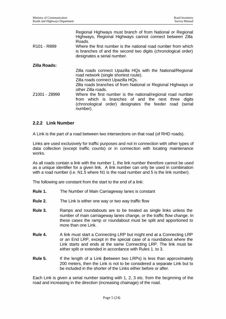
Regional Highways must branch of from National or Regional Highways, Regional Highways cannot connect between Zilla Roads.
R101 - R899 Where the first number is the national road number from which is branches of and the second two digits (chronological order) designates a serial number.
Zilla Roads: Zilla roads connect Upazilla HQs with the National/Regional
road network (single shortest route). Zilla roads connect Upazilla HQs. Zilla roads branches of from National or Regional Highways or
other Zilla roads. Z1001 - Z8999 Where the first number is the national/regional road number
from which is branches of and the next three digits (chronological order) designates the feeder road (serial number).
2.2.2 Link Number A Link is the part of a road between two intersections on that road (of RHD roads). Links are used exclusively for traffic purposes and not in connection with other types of data collection (except traffic counts) or in connection with locating maintenance works. As all roads contain a link with the number 1, the link number therefore cannot be used as a unique identifier for a given link. A link number can only be used in combination with a road number (i.e. N1.5 where N1 is the road number and 5 is the link number). The following are constant from the start to the end of a link: Rule 1. The Number of Main Carriageway lanes is constant Rule 2. The Link is either one way or two way traffic flow Rule 3. Ramps and roundabouts are to be treated as single links unless the
number of main carriageway lanes change, or the traffic flow change. In these cases the ramp or roundabout must be split and apportioned to more than one Link.
Rule 4. A link must start a Connecting LRP but might end at a Connecting LRP
or an End LRP, except in the special case of a roundabout where the Link starts and ends at the same Connecting LRP. The link must be either split or extended in accordance with Rules 1. to 3.
Rule 5. If the length of a Link (between two LRPs) is less than approximately
200 meters, then the Link is not to be considered a separate Link but to be included in the shorter of the Links either before or after.
Each Link is given a serial number starting with 1, 2, 3 etc. from the beginning of the road and increasing in the direction (increasing chainage) of the road.

Ministry of Communication Road Inventory Roads and Highways Department Survey Manual
Page 6 (24)
A unique serial number is given to each Link within each Road. For example: N1.1, N1.2, N1.3 etc R101.1, R101.2, R101.3 etc Z3015.1, Z3015.2, Z3015.3 etc. Dual carriageways get the link extension L (left) and R (right) this distinguishes the individual sides in the RMMS and when the HDM carries out the planning and programming runs.
RCL
RCL
RCL
RCL
RCL
RCL
RCL
RCL RCL
Link 1 Link 2 Link 3LLink 3R
Link 3L
Link 3R
Link 4L
Link 4RLink 4L
Link 4R
Link 5 Link 6
LRPELRPS
Single Carriageway Single CarriagewayDual Carriageway If a link has to be split because a new road joining the link then the following rule is to be used:
RCL
RCL
RCL
RCL
RCL
RCL
RCL
RCL RCL
Link 1 Link 2a Link 3LLink 3R
Link 3L
Link 3R
Link 4L
Link 4RLink 4L
Link 4R
Link 5 Link 6
LRPELRPS
Single Carriageway Single CarriagewayDual Carriageway
RCL
Link 2b
New Road Link N1.2 is split into two new links given the following numbers: N1.2a and N1.2b. Extension (for example .2a) for a split of links will be shown before the extension for dual carriageway (for example .2aL)

Ministry of Communication Road Inventory Roads and Highways Department Survey Manual
Page 7 (24)
3. LOCATION REFERENCE POINTS This chapter describes RMMS Location Referencing principles along with a number of other fundamental and important associated concepts. 3.1 OBJECTIVE Location Referencing comprises the concepts and techniques used to define how the spatial and temporal position and events in the physical world are reflected within the computer system and vice versa. Thus Location Referencing is the foundation on which the computerised model of the road is built and is the foundation of the RMMS. The purpose of the Location Reference Point (LRP) Survey is to establish the location of LRPs, the distance between adjacent LRPs and the GPS coordinates for the LRPs that make up a road. The RHD has adopted a LRP system based on Km stones, bridges etc. for referencing its roads. 3.2 PROCEDURE The locations of Location Reference Points (LRPs) shall be established during the survey. In many instances these will be the existing km posts (Primary LRP) or, if km posts are missing, other fixed points (bridges etc. – Secondary LRP) adjacent to the carriageway. Distance between LRP’s shall be measured with 1 (one) meter accuracy and the location of each LRP measured by GPS (Longitude/Latitude). LRPs shall be clearly identified and located in a position which is easily visible, by future assessment teams. The offset direction and the LRP numbers should increase in terms of increasing km post numbers (Chainage). If there are no km posts on a road, the LRPs are defined as increasing from the start of the roads to the end of the road. For storage in the Road Maintenance Management System (RMMS) all data items collected in the project should be referenced using the following tentative Location Referencing System (LRS): 1. Road Number; 2. Km Reference (chainage/distance measurement from start of the road); 3. GPS Co-ordinates

Ministry of Communication Road Inventory Roads and Highways Department Survey Manual
Page 8 (24)
Table 3.1 Location Reference Objects Event Feature Location GPS
Coordinates Description
Start of Road Start Location of Road
Yes What is road connected to Where it starts from Name of location (Junction, bazaar, city, etc.)
End of Road End Location of Road Chainage from start of road
Yes Where it ends Name of Location (Junction, bazaar, city, etc.)
Km Posts Location of Km Posts
Yes Chainage from start of road Chainage from start of link Chainage from last Km post Description of km post
Bridges Chainage from start of road
Yes Description of type of bridge Length of bridge Width of bridge
Culverts Chainage from start of road
Yes Description of type of culvert (pipe/box) Size of culvert
Ferry Ghat Chainage from start of road
Yes Width of river
Road Junctions (intersections) (L or R)
Chainage from start of road
Yes Description of type of junction(intersection) (T-, Y-, X– junction)
Railway Crossing Chainage from start of road
Yes Number of tracks
Toll Plaza Chainage from start of road
Yes Length of toll plaza Width of toll plaza
Primary Location Reference Points are Km posts. Km posts only (also missing) are given whole numbers such as: LRP001 LRP002 LRP003 Etc. A missing km post is assumed to be located 1,000m from the last km post. Secondary Location Reference Points are all other referensable objects named in the above table. Secondary LRPs (see above list) are identified by the LRP number plus an additional letter such as: LRP001 LRP001a (for example the first structure located between LRP001 and LRP002) LRP001b (for example an intersection located after the bridge (LRP001a) and
between LRP001 and LRP002) LRP002 LRP002a (for example an intersection located between LRP002 and LRP003) LRP003

Ministry of Communication Road Inventory Roads and Highways Department Survey Manual
Page 9 (24)
An example of a surveyed road is given in Appendix 1. Structures with a total span of 10m or more are to be recorded as bridges and an LRP to be established at the start and end of the bridge. Start LRP of a bridge is where the abutment ends and the bridge/culvert begin, same for the end of the bridge, see picture below.
3.2.1 Description of Km posts The LRP survey form held two fields for description of the Km posts. A short description and a long description, the short description is mainly indicating the distance from the km post to the start of the road. The long description is indicating distances to the next city. See picture below:

Ministry of Communication Road Inventory Roads and Highways Department Survey Manual
Page 10 (24)

Ministry of Communication Road Inventory Roads and Highways Department Survey Manual
Page 11 (24)
4. CROSS SECTION INVENTORY 4.1 OBJECTIVE The first of the Network Level Surveys is the Cross-Section Survey. This survey should be a one-time survey of Cross-Section items on the network. It does not need to be repeated annually. The data to be collected during this survey are continuous section data. One of the objectives of carrying out Pavement Inventories is to measure the width of carriageway, shoulder, non-motorized lanes etc. which form part of the crest of the road. 4.2 PROCEDURE There are two main types of road inventory data to be collected, each of which needs a different and individual data collection treatment. These are ‘Section’ or ‘Continuous’ data and ‘Event’ or ‘Discrete’ data. Continuous / Section Data This data type relates to data that can be termed continuous and has both a defined ‘Start’ and ‘End’ point to which a chainage can be given and which can be measured therefore in linear or square meters e.g. drainage ditch types, guard-rail and other fences, kerbs, shoulders, traffic lanes, verges, traffic markings, bus bays, bicycle lanes, foot patch etc. In addition to the chainage data it is normal practice to also provide a record of the offset from the centre-line so as to identify exactly the cross-section details of the road. Discrete / Event Data This data types relates to discrete event data that can be adequately described by a single chainage and an off-set from the centre-line. Such items are: - drainage outlets (catch-pits, outfalls, drop-inlets, gullies and slope drains etc.), road signs, stop-lines, pedestrian crossings, man-holes, railway level-crossings, roadway lighting poles, traffic signals, kilometre posts, guide posts, overbridges, overhead transmission lines, utility poles and the like. All inventory data collection demands significant time and human resource inputs. It can only be done by manually recording the presence and location of each inventory item. (a) The width of the pavement, shoulders and verge is measured to the nearest
10cm at the beginning of the road and recorded. Type of pavement and shoulders are also recorded
(b) The observation of cross section widths should be done on foot. If any element
changes, the new width of each element in the cross section is measured (also these not changing) and data is recorded on the survey form together with the chainage in which the change takes place.
(c) If there is no change of item width in the cross section, observation can be
continued to the end of the road.

Ministry of Communication Road Inventory Roads and Highways Department Survey Manual
Page 12 (24)
The following types of Verges, Shoulders and Surface are normally found in Bangladesh: Verge Types Shoulder Types Surface Types 1. None 1. None 1. None 2. Earth (ER) 2. Earth (ER) 2. Bituminous 3. Bituminous (BIT) 3. HBB 4. HBB 4. Earth (ER) 5. Water Bound Macadam (WB) 5. Cement Concrete (CC) Appendix 2 contains cross section inventory forms for single as well as dual carriageways.
Ministry of Communication Road Inventory Roads and Highways Department Survey Manual
Page 13 (24)
5. DRAINAGE INVENTORY 5.1 OBJECTIVE The drainage survey should be a one-time survey and is part of the road Cross-Section Inventory. It does not need to be repeated annually. The data to be collected during this survey are continuous section data. One of the objectives of carrying out Pavement Inventories is to measure the width of carriageway, shoulder, non-motorized lanes etc. which form part of the crest of the road. 5.2 PROCEDURE All inventory data collection demands significant time and human resource inputs. It can only be done by manually recording the presence and location of each inventory item. (a) The width of the drainage and the distance from centerline is measured to the
nearest 10cm at the beginning of the road and recorded. Type of drainage are also recorded
(b) The observation of cross section widths should be done on foot. If any element
changes, the new width and/or type of drainage is measured (also these not changing) and data is recorded on the survey form together with the chainage in which the change takes place.
(c) If there is no change of item width and/or type of drainage in the cross section,
observation can be continued to the end of the road. The following types of drainage are normally found in Bangladesh: 1. None 2. Earth plain 3. Rock plain 4. Grassed plain 5. Lined masonry 6. Lined pitchstone 7. Lined concrete Appendix 3 contains cross section inventory forms for drainage survey.
Ministry of Communication Road Inventory Roads and Highways Department Survey Manual
Page 14 (24)
6. PAVEMENT HISTORY 6.1 OBJECTIVE The survey is intended to identify when and how the pavement was originally constructed and what maintenance has been carried out since. 6.2 PROCEDURE The main sources from which relevant data can be obtained are: • As-built drawings (indicating year of construction); • Engineers, technicians and foremen with long service record; and • Test pits and/or DCP testing If the first two items are unavailable, the actual construction might have to come from test pits or from DCP testing. The main part of the work can be carried out in the office going through the as-built drawings received from contractors over the years. Supplementary information can normally be obtained from engineers, technicians and foremen. For roads where no information can be obtained from in-house records, information should be obtained from either test pits or from DCP testing – see separate Manual (DCP & Test Pits Survey Manual). The pavement construction survey form to be used is shown in Appendix X

Appendices

APPENDIX 1 LOCATION REFERENCE POINT SURVEY FORM

ROADS AND HIGHWAYS DEPARTMENT
LRP NO ChainageLRP Type
Referencable (Y/N)
Reference LRP
Offset from Ref LRP
Parpendicular distance from centre line (m)
Short description of LRP
Longitude Latitude
LRP Types LRP Types LRP Types1. Km Post 5. Turn off, Left 9. Bridge2. Cross Road 6. Turn off, Right 10. Culvert3. Side Road, Left 7. Round About 11. Monument4. Side Road, right 8. Rail Road Crossing 12. Others
Location Reference Point (LRP)
Long Description and Remarks
Road no Road Name Date of Survey
SurveyorName:
Signature:

ROADS AND HIGHWAYS DEPARTMENT
LRP NO Chainage LRP Type
Referencable (Y/N)
Reference LRP
Offset from Ref LRP
Parpendicular distance from centre line (m)
Short description of LRP Longitude Latitude
LRPS 0 12 Y - - - Start of Road 90.437969 23.709258 LRP001 0.985 1 Y LRPS 0.985 7 Km Post 5 90.437969 23.709611 LRP002 1.994 1 Y LRP1 1.009 6.9 Km Post 6 90.471238 23.709643 LRP003 2.994 1 N - 1.000 0 Km Post 6, Missing
LRP003a 3.567 4 N LRP002 1.573 0 Sideroad Left side 90.460002 23.708123 LRP004 4.001 1 Y LRP002 2.007 7 Km Post 8 90.459875 23.707345
LRP004a 4.599 3 N LRP004 0.598 0 Sideroad Right Side 90.45789 23.702222 LRP004b 4.756 9 N LRP004 0.755 0 Bridge 90.451234 23.700043 LRP005 5.005 1 Y LRP005 1.004 6.8 Km Post 9 90.447632 23.694723 LRP005a 5.607 4 N LRP005 0.602 0 Sideroad Right Side 90.439993 23.693214 LRP006 5.998 1 Y LRP005 0.993 6.8 Km Post 10 90.436789 23.691234 LRPE 7.567 12 N LRP006 - 0 End of Road 90.425678 23.683456
LRP Types LRP Types LRP Types 1. Km Post 5. Turn off, Left 9. Bridge 2. Cross Road 6. Turn off, Right 10. Culvert 3. Side Road, Left 7. Round About 11. Monument 4. Side Road, right 8. Rail Road Crossing 12. Others
Chittagong 241, Comilla 74
Location Reference Point (LRP)
Long Description and Remarks
Roundabout ........ Chittagong 245, Comilla 78 Chittagong 244, Comilla 77
D1234 to Asasuni Chittagong 242, Comilla 75
R207 to Kalaroa Bridge over Jamuna
R208 Chittagong 240, Comilla 73
D1235 to Jessore
Road no N1
Road Name Dhaka - Chittagong - Teknaf
Date of Survey 20 - 05 -2004
Surveyor Name:
Signature:

APPENDIX 2 ROAD INVENTORY SURVEY FORMS

ROADS AND HIGHWAYS DEPARTMENT
Road no
End LRP+Offset(m)
Footpath FootpathWidth
(m)Type
Width (m)
Type Width (m) Surface Type Width (m) Width (m)Width
(m)Type
Width (m)
Type
Footpath Footpath
Verge Types Shoulder Types Surface Types1. Earth (ER) 1. Earth (ER) 1.Bituminous
2. Bituminous (BIT) 2.HBB3. HBB 3. Earth (ER)4. Water Bound Macadam (WB) 4. Cement Concrete (CC)
Shoulder Shoulder VergeCarriageway
Verge
Road Inventory Survey (Single Carriageway)
Road Name Date of Survey
Carriageway Shoulder VergeShoulder
Verge
Start LRP+Offset(m)
Signature of the Surveyor

ROADS AND HIGHWAYS DEPARTMENT
Road no
Carriageway (L/R):
Footpath Median FootpathWidth (m)
TypeWidth
(m)Type Width (m)
Surface Type
Width (m)
Width (m)
Surface Type
Width (m) Width (m)Width (m)
TypeWidth (m)
Type
Footpath Median Footpath
Verge Types Shoulder Types Surface Types1. None 1. None 1. None2. Earth (ER) 2. Earth (ER) 2. Bituminous
3. Bituminous (BIT) 3. HBB4. HBB 4. Earth (ER)5. Water Bound Macadam (WB) 5. Cement Concrete (CC)
Road Inventory Survey (Dual Carriageway)
Road Name Date of Survey
Verge Shoulder VergeShoulder
Shoulder Shoulder Verge
Start LRP+Offset(m) End LRP+Offset(m)
Verge
Carriageway (left) Carriageway (right)
Carriageway Carriageway (right)
Signature of the Surveyor

APPENDIX 3 DRAINAGE INVENTORY SURVEY FORM

ROADS AND HIGHWAYS DEPARTMENT
Type Type
Drain Types Drain Types1. None 5. Lined masonry2. Earth plain 6. Lined pitchstone3. Rock plain 7. Lined concrete4. Grassed plain
Inventory of Drainage
LRP + offset(m)LRP + offset(m) ChainageChainage
Start point End pointLeft side drain Right side drain
Road no Road Name Date of Survey
SurveyorName:
Signature:

APPENDIX 4 HISTORY INVENTORY SURVEY FORM
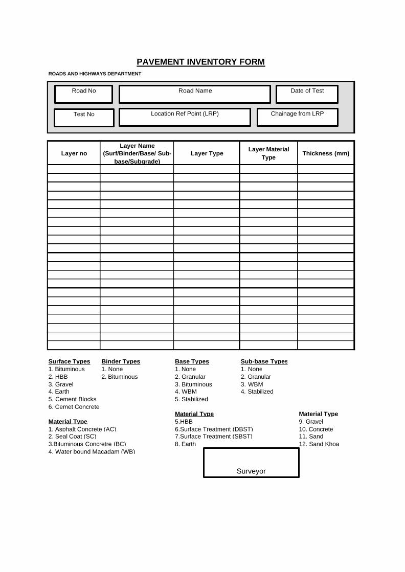
ROADS AND HIGHWAYS DEPARTMENT
Layer noLayer Name
(Surf/Binder/Base/ Sub-base/Subgrade)
Layer TypeLayer Material
TypeThickness (mm)
Surface Types Binder Types Base Types Sub-base Types1. Bituminous 1. None 1. None 1. None2. HBB 2. Bituminous 2. Granular 2. Granular3. Gravel 3. Bituminous 3. WBM4. Earth 4. WBM 4. Stabilized5. Cement Blocks 5. Stabilized6. Cemet Concrete
Material Type Material TypeMaterial Type 5.HBB 9. Gravel1. Asphalt Concrete (AC) 6.Surface Treatment (DBST) 10. Concrete2. Seal Coat (SC) 7.Surface Treatment (SBST) 11. Sand3.Bituminous Concretre (BC) 8. Earth 12. Sand Khoa4. Water bound Macadam (WB)
PAVEMENT INVENTORY FORM
Road No Road Name
Location Ref Point (LRP)Test No
Date of Test
Chainage from LRP
Surveyor