Embed Size (px)
Citation preview
PAVEMENT MANAGEMENT PROGRAM
FOR
GENERAL AVIATION AIRPORTS
PREPARED BY:
THE AVIATION DIVISIONTEXAS DEPARTMENT OF TRANSPORTATION
125 E. 11th STREETAUSTIN, TEXAS
78701-2483
( 512 ) 416-4500
1(800) 86-PILOT
2
January 2000
Dear Airport Sponsor:
The attached Pavement Management Program has been prepared for your airport. Itcontains four chapters, which include the following information:
Chapter 1 INTRODUCTION, which gives background information onpavement management programs, their cost benefits, and theirbasic components,
Chapter 2 F.A.A. REQUIRED ELEMENTS, which describes the minimumcomponents of a pavement management program which meetsFAA requirements for federally funded airport improvementprojects,
Chapter 3 ROUTINE AIRPORT MAINTENANCE PROGRAM, whichdescribes the Aviation Division’s RAMP program designed toassist airport owners and operators in performing routine pavementmaintenance.
Chapter 4 MONTHLY INSPECTION RECORDS, which includes an airportpavement layout sketch, the pavement inspection sections, and therecord keeping forms for each section, to be filled out and dated bythe designated pavement manager for your airport. These recordsmust be retained in your permanent files for a minimum of fiveyears, and copies must be available on request by the FAA andTxDOT,
Appendix 1 PAVEMENT MAINTENANCE METHODS, which provides anoverview of common pavement distresses, identification of distresstypes and causes, and recommended maintenance activities,
Appendix 2 PAVEMENT MANAGEMENT SYSTEMS, which includes areprint of the FAA Advisory Circular Number 150/5380-7 titled “A Pavement Management System”.
If you have any questions about the Pavement Management Program, please call theAviation Division of the Texas Department of Transportation at 1 (800) 68-PILOT, orwrite us at 125 E. 11th Street, Austin, Texas 78701-2483.
3
PAVEMENT MANAGEMENT PROGRAM
1 INTRODUCTION
2 F.A.A. REQUIRED ELEMENTS
3 ROUTINE AIRPORT MAINTENANCE PROGRAM
4 MONTHLY INSPECTION RECORDS
APPENDIX 1: PAVEMENT MAINTENANCE METHODS
APPENDIX 2: PAVEMENT MANAGEMENT SYSTEMS
4
FAA PAVEMENT MAINTENANCE / MANAGEMENT REQUIREMENTS
As part of the Federal Aviation Administration’s (FAA) Airport Improvement Program (AIP) funds, Congress has mandated that facilities receiving federal monies forreplacement or reconstruction of paved surfaces must create a pavement maintenance /management program.
Historically, the FAA and TxDOT have assisted sponsors in improving runways,taxiways, and aprons by contributing 90% of the project cost. Appropriate and timelymaintenance will prolong pavement life, maintain a high level of ride quality, and reducethe lifetime cost of the pavement. Unfortunately, in the past, the pavement often did notreceive any preventive or remedial maintenance after it was constructed.
Since January 1, 1995 airport sponsors that accept AIP funds for pavement replacementor reconstruction are required to commit to a grant assurance which stipulates that aneffective pavement maintenance / management program will remain in effect throughoutthe useful life of the constructed pavement. Such a program will have four basiccomponents:
- a pavement inventory which shows the dimensions, locations, and maintenance history of all paved surfaces,
- a prescribed inspection schedule, which will minimally involve detailed annual assessments, and monthly drive-by observations,
- record keeping which documents inspection dates, findings, locations of distress, and remedial actions scheduled and performed,
- a method of data retrieval which would permit a comprehensive presentation to the FAA if they request one.
A thoughtfully conceived pavement maintenance/management program creates a win-winsituation. Your airport will have a logical and structured method of addressingmaintenance requirements in a timely fashion. This will minimize your costs. Andrepairing and rehabilitating pavements, rather than reconstructing pavements, will allowTxDOT to maximize state and federal dollars for system improvements.
5
PAVEMENT MANAGEMENT PROGRAM
1 INTRODUCTION
2 F.A.A. REQUIRED ELEMENTS
3 ROUTINE AIRPORT MAINTENANCE PROGRAM
4 MONTHLY INSPECTION RECORDS
APPENDIX 1: PAVEMENT MAINTENANCE METHODS
APPENDIX 2: PAVEMENT MANAGEMENT SYSTEMS
6
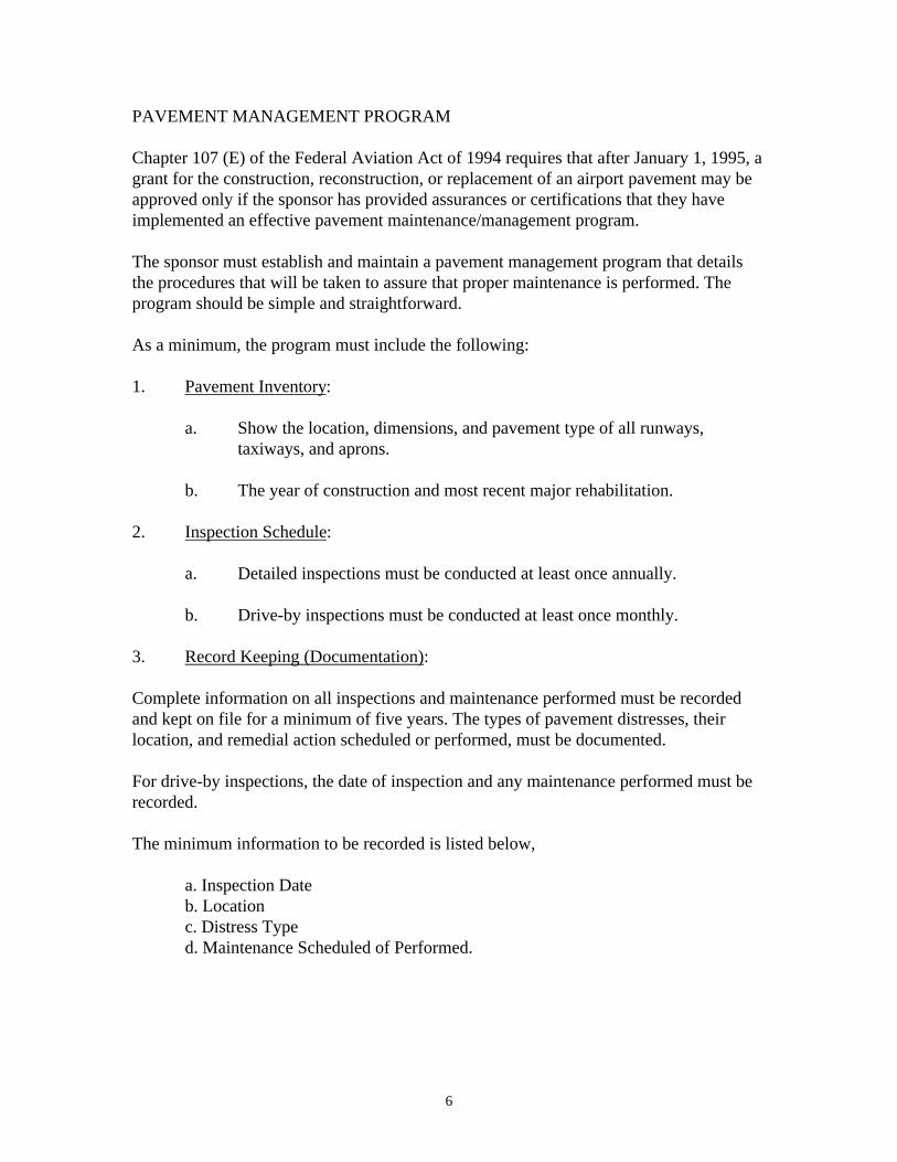
PAVEMENT MANAGEMENT PROGRAM
Chapter 107 (E) of the Federal Aviation Act of 1994 requires that after January 1, 1995, agrant for the construction, reconstruction, or replacement of an airport pavement may beapproved only if the sponsor has provided assurances or certifications that they haveimplemented an effective pavement maintenance/management program.
The sponsor must establish and maintain a pavement management program that detailsthe procedures that will be taken to assure that proper maintenance is performed. Theprogram should be simple and straightforward.
As a minimum, the program must include the following:
1. Pavement Inventory:
a. Show the location, dimensions, and pavement type of all runways,taxiways, and aprons.
b. The year of construction and most recent major rehabilitation.
2. Inspection Schedule:
a. Detailed inspections must be conducted at least once annually.
b. Drive-by inspections must be conducted at least once monthly.
3. Record Keeping (Documentation):
Complete information on all inspections and maintenance performed must be recordedand kept on file for a minimum of five years. The types of pavement distresses, theirlocation, and remedial action scheduled or performed, must be documented.
For drive-by inspections, the date of inspection and any maintenance performed must berecorded.
The minimum information to be recorded is listed below,
a. Inspection Dateb. Locationc. Distress Typed. Maintenance Scheduled of Performed.
7
4. Information Retrieval:
An airport sponsor may use any form of record keeping it deems appropriate, as long asthe information and records may be retrieved to provide a report to the FAA as may berequired.
Records of materials and equipment used to perform maintenance should be kept on filefor future reference. These records may be used to identify materials and remedialmeasures which may reduce maintenance costs and improve pavement serviceability.Unless adequate records are kept, there will be no benefit to the future use of thisinformation to possibly reduce your maintenance costs.
Remember, if inspections and remedial actions are not documented, then they did notoccur. Documentation is vital.
8
PAVEMENT MANAGEMENT PROGRAM
1 INTRODUCTION
2 F.A.A. REQUIRED ELEMENTS
3 ROUTINE AIRPORT MAINTENANCE PROGRAM
4 MONTHLY INSPECTION RECORDS
APPENDIX 1: PAVEMENT MAINTENANCE METHODS
APPENDIX 2: PAVEMENT MANAGEMENT SYSTEMS
9
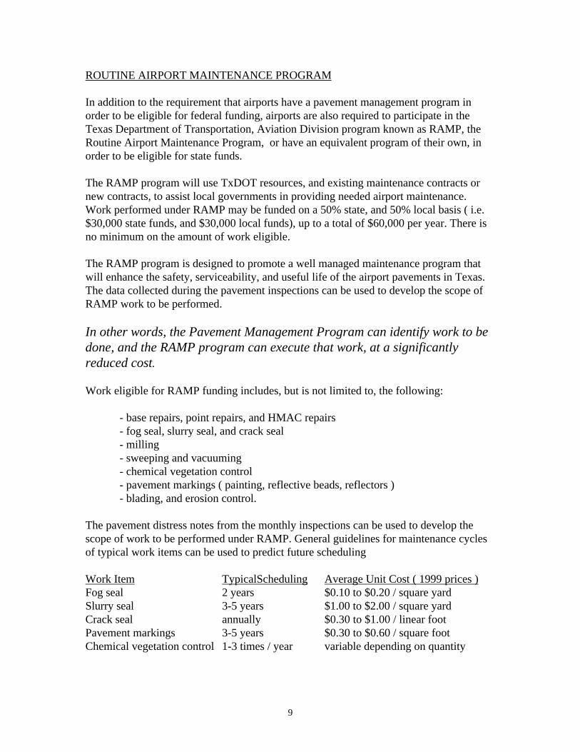
ROUTINE AIRPORT MAINTENANCE PROGRAM
In addition to the requirement that airports have a pavement management program inorder to be eligible for federal funding, airports are also required to participate in theTexas Department of Transportation, Aviation Division program known as RAMP, theRoutine Airport Maintenance Program, or have an equivalent program of their own, inorder to be eligible for state funds.
The RAMP program will use TxDOT resources, and existing maintenance contracts ornew contracts, to assist local governments in providing needed airport maintenance.Work performed under RAMP may be funded on a 50% state, and 50% local basis ( i.e.$30,000 state funds, and $30,000 local funds), up to a total of $60,000 per year. There isno minimum on the amount of work eligible.
The RAMP program is designed to promote a well managed maintenance program thatwill enhance the safety, serviceability, and useful life of the airport pavements in Texas.The data collected during the pavement inspections can be used to develop the scope ofRAMP work to be performed.
In other words, the Pavement Management Program can identify work to bedone, and the RAMP program can execute that work, at a significantlyreduced cost.
Work eligible for RAMP funding includes, but is not limited to, the following:
- base repairs, point repairs, and HMAC repairs- fog seal, slurry seal, and crack seal- milling- sweeping and vacuuming- chemical vegetation control- pavement markings ( painting, reflective beads, reflectors )- blading, and erosion control.
The pavement distress notes from the monthly inspections can be used to develop thescope of work to be performed under RAMP. General guidelines for maintenance cyclesof typical work items can be used to predict future scheduling
Work Item TypicalScheduling Average Unit Cost ( 1999 prices )Fog seal 2 years $0.10 to $0.20 / square yardSlurry seal 3-5 years $1.00 to $2.00 / square yardCrack seal annually $0.30 to $1.00 / linear footPavement markings 3-5 years $0.30 to $0.60 / square footChemical vegetation control 1-3 times / year variable depending on quantity

10
Other maintenance items such as base repairs, point repairs, HMAC repairs, milling,sweeping, blading, and erosion control are typically performed on an as needed basis.
Using current maintenance costs and quantities it is very easy to estimate the cost forfuture maintenance work, and schedule and budget accordingly. Contact your localTxDOT representative to coordinate RAMP work at your airport, or contact the AviationDivision at 1(800)68-PILOT for more information.
11
PAVEMENT MANAGEMENT PROGRAM
1 INTRODUCTION
2 F.A.A. REQUIRED ELEMENTS
3 ROUTINE AIRPORT MAINTENANCE PROGRAM
4 MONTHLY INSPECTION RECORDS
APPENDIX 1: PAVEMENT MAINTENANCE METHODS
APPENDIX 2: PAVEMENT MANAGEMENT SYSTEMS
12
MONTHLY FIELD INSPECTIONS
As discussed in previous chapters, the airport pavement areas must be inspected, aminimum of once per month.
The airport should be divided into discreet pavement sections, as shown on the PavementSection Drawing. Each section should have a separate sheet for recording the monthlyobserved pavement condition and distresses. A sample sheet has been included forreference. A blank form is included. Make multiple copies and use as needed.
Refer to Appendix 1 and Appendix 2 for additional information regarding distresses andmaintenance.
HOW TO PERFORM THE INSPECTION:
To complete the monthly inspection:
1) Walk or slowly drive the airport pavements, looking for any irregularities,damage, or deficiencies.
2) Make written notes describing the date, the pavement section, the location, thetype, and the extent of the problems. Forms are attached for this purpose.
3) Note the corrective action taken, or to be taken, including the date of action.
It is very helpful to inspect the pavements either early or late in the day, when the sun islow to the horizon, or just after a rain. At these times, shadows or moisture highlightdeformities in the pavement surface.
On runways, it is helpful to reference locations to runway lights. They should havenumbered tags attached to each fixture.
Remember, to paraphrase Yogi Berra, “ It’s amazing what you can see, just by lookingaround.”

13
AIRPORT:
LOCATION: SECTION: DIMENSIONS:
CONSTRUCTION HISTORY:
MONTHLY INSPECTION NOTES:

14
MONTHLY INSPECTION NOTES:
15
PAVEMENT MANAGEMENT PROGRAM
1 INTRODUCTION
2 F.A.A. REQUIRED ELEMENTS
3 ROUTINE AIRPORT MAINTENANCE PROGRAM
4 MONTHLY INSPECTION RECORDS
APPENDIX 1: PAVEMENT MAINTENANCE METHODS
APPENDIX 2: PAVEMENT MANAGEMENT SYSTEMS
16
PAVEMENT MAINTENANCE
In operating and maintaining an airport, managers and maintenance personnel are continuallyfaced with problems involving pavement distress and deterioration. Age, weather, andordinary use are some of the causes of pavement damage. This chapter will provideinformation on types of pavement distress, and recommend corrective actions.
PAVEMENT TYPES
Airport pavements are designed, constructed, and maintained to support the critical loadsimposed on the pavement and to produce a smooth and safe riding surface. The pavementmust be of such quality and thickness that it will not fail under the loads of aircraft and bedurable enough to withstand the abrasive action of traffic, adverse weather conditions, andother deteriorating influences. Pavements are divided into three classes: rigid, flexible, andoverlays.
RIGID PAVEMENTS (PCC)
Rigid pavements normally involve the use of Portland cement concrete (PCC) as the primestructural element. Depending upon conditions, the pavement slab may be designed withplain, lightly reinforced, continuously reinforced, prestressed, or fibrous concrete. Theconcrete slab is usually placed on a compacted granular subbase which, in turn, is supportedby a compacted subgrade. A typical rigid pavement structure possesses a high degree ofrigidity. This rigidity and resulting beam action enables rigid pavements to distribute loadsover large areas of the subgrade. For better pavement performance, it is important thatsupport for the entire concrete slab is uniform. Rigid pavement construction strength is mosteconomically built into the slab itself with optimum use of low-cost materials under the slab. Rigid pavement consists of the following layers:
Concrete Slab (Surface Layer) - Provides a skid-resistant surface, prevents the infiltrationof surface water, and provides structural support to the aircraft.
Subbase - Provides uniform, stable support for the pavement slab. A minimum subbasethickness of 4 inches is generally required under rigid pavements. Other functions of thesubbase are to control frost action, provide subsurface drainage, control swell of subgradesoils, and prevent mud pumping of fine grained soils.
17
Stabilized Subbase - Required for all new rigid pavements designed to accommodateaircraft weighing 100,000 pounds or more.
Frost Protection Layer - Rare in Texas, but provides a barrier against frost action and frostpenetration into the lower frost-susceptible layers.
Subgrade - Compacted soil layer which forms the foundation for the pavement system. Subgrade soils are subjected to lower stresses than the surface and subbase courses. These stresses decrease with depth, and the controlling subgrade stress is usually at thetop of the subgrade unless unusual conditions exist. Soil conditions are related to theground water level, density, moisture content, and frost penetration. Since the subgradesoil supports the pavement and the loads imposed on the pavement surface, it is critical toinvestigate soil conditions to determine their effect on grading and paving operations andthe necessity for underdrains.
FLEXIBLE PAVEMENTS (HMAC)
Flexible pavements support loads through bearing rather than flexural action; that is, theytransmit their strength through several layers. Thus, they are composed of several layers ofcarefully selected materials designed to gradually distribute loads from the pavement surfaceto the layers underneath. The design is such that the load transmitted to each successive layerdoes not exceed the layer's load bearing capacity. The distribution of the load, from thesurface on down through the lower layers of the pavement structure, covers a larger andlarger area as the load penetrates the pavement toward the subgrade. The various layers ofa flexible pavement and their functions are as follows:
Bituminous Surface or Wearing Course - Bituminous (petroleum product found in tar orcoal [asphalt]) surface, or wearing course, comprised of a mixture of various selectedaggregates bound together with asphalt cement, heavy grades of tars, or other bituminousbinders. Its function is to prevent the penetration of water to the base course; provide asmooth, well-bonded surface free from loose particles (which might endanger aircraft orpersons); resist the stresses developed as a result of aircraft loads; and furnish askid-resistant surface without causing undue wear on tires.
Base Course - Principal structural component of the flexible pavement. It distributes theimposed wheel load to the pavement foundation, the subbase and/or the subgrade. Thebase course must be of a quality and thickness to prevent failure in the subgrade and/or
18
the subbase, withstand the stresses produced in the base itself, resist vertical pressuresthat tend to produce consolidation and a result in distortion of the surface course, andresist volume changes caused by fluctuations in its moisture content. The materials thatcompromise the base course are select, hard and durable aggregates which generally fallinto two main classes: stabilized and granular. The stabilized bases normally consist ofcrushed and uncrushed aggregate that has been bound with a stabilizer such as cement orbitumen. The quality of the base course is a function of its composition, physicalproperties, and compaction of the material.
Subbase - Layer used in areas where frost action is severe or in locations where thesubgrade soil is extremely weak. The function of the subbase course is similar to the basecourse. The material requirements for the subbase are not as strict as those for the basecourse since the subbase is subjected to lower load stresses. The subbase consists ofstabilized or granulated materials properly compacted.
Frost Protection Layer - Once again, rare in Texas. The frost protection layer functions asmentioned in Paragraph 4 under rigid pavements.
Subgrade - Compacted soil layer which forms the foundation for the pavement system. Subgrade soils are subjected to lower stresses than the surface, base, and subbase courses.Since load stresses decrease with depth, the controlling subgrade stress is usually at thetop of the subgrade. The combined thickness of subbase, base, and wearing surface mustbe great enough to reduce the stresses occurring in the subgrade soil layer. Factorsaffecting subgrade behavior are discussed in Paragraph 5 under rigid pavements.
OVERLAYS
Pavement overlays are usually undertaken to correct deteriorating pavement surfaces, toimprove ride quality or surface drainage, to maintain the structural integrity, or to increasepavement strength. For instance, a pavement may have been damaged by overloading; itmay require strengthening to serve heavier aircraft; uneven settling may have caused severepuddling; or the original pavement simply may have served it useful life and be worn out.
19
PAVEMENT DISTRESS
The deterioration of a pavement, be it runway or highway, manifests itself by variousexternal signs or indicators which can be associated with the probable causes of the failureor imperfection. Discussions of problems relating to pavement distress are generally basedon pavement type, either concrete or bituminous. However, while each possesses its ownparticular characteristics, the various pavement distress manifestations for bituminous andconcrete pavements generally fall into one of the following broad categories: cracking,distortion, disintegration, or skid resistance. The indicated repair procedures are advisoryin nature. In no way should they be taken over the advice of an experienced engineer, whoshould be consulted before undertaking any large repair project.
CONCRETE PAVEMENTS
Portland Cement Concrete (PCC) pavements are subject to the following distresses:
Blowups FaultingContaminants Joint Seal DamageCracking, Longitudinal Polished AggregateCracking, Transverse PumpingCracking, Diagonal RoughnessCracking, Corner Shattered SlabCracking, “D” Spalling, JointCracking, Shallow Spalling, CornerDistortion Skid Resistance
BLOWUPS (PCC)
Blowups usually occur at a transverse crack or joint. They generally occur in hot weather,usually at a transverse crack in the joint that is not wide enough to permit expansion of theconcrete slabs. Insufficient width is usually caused by infiltration of incompressiblematerials into the joint space. When expansion cannot relieve enough pressure, a localizedupward movement of the slab edges (buckling) or shattering will occur in the vicinity of thejoint. Blowups normally occur only in thin pavement sections.
Repair Procedure:-Make a vertical cut with a concrete saw approximately 6 inches outside of each end of the
broken area.-Break out the concrete with pneumatic tools and remove concrete down to the
subbase/subgrade material.
20
-Add subbase material, if necessary, and compact-In reinforced pavement construction, joint techniques should be used to tie the new concrete
to the old reinforced material. Any replacement joints should be doweled and built tojoint specifications. For simplicity of construction, all tiebars, dowels, and reinforcementmay be omitted from small interior pavement patches on well-compacted subgrades.
-Dampen the subgrade and the edges of the old concrete.-Place the concrete.-Use ready-mix concrete if it is satisfactory and can be obtained economically. It may be
desirable to use a mixture providing high early strength in order to permit the earliestpossible use.
-Finish the concrete so that the surface texture approximates that of the existing pavement.-Immediately after completing the finishing operations, the surface should be properly cured.
Either a moist cure or curing compound may be used.
CONTAMINANTS (PCC)
Contaminants such as rubber deposits building up over a period of time will reduce thesurface friction characteristics of a pavement.
Repair Procedure:Rubber deposits may be removed by use of high-pressure water or biodegradable chemicals.
CRACKING (PCC)
Cracking often results from stresses caused by contraction or warping of the pavement. Overloading, loss of subgrade support, insufficient and/or improperly cut joints actingsingularly or in combination is also possible causes. The following are types of cracks inconcrete pavement:
CRACKS; LONGITUDINAL, TRANSVERSE, AND DIAGONAL (PCC)
Longitudinal, transverse, and diagonal cracks are usually caused by a combination ofrepeated loads and shrinkage stresses and are characterized by cracks which divide theslab into two or more pieces.
Repair Procedure:-Route out a groove about 3/8 inch wide and 3/4 inch deep around the crack.-Clean out with compressed air. The crack must be free of dirt, dust, and other material
21
that might prevent bonding of the sealant. Fill the crack with sealant materials.
CRACKS; CORNER (PCC)
Corner cracks are caused by load repetition combined with loss of support and curlingstresses. This type of break is characterized by a crack that intersects the joints at adistance less than one-half of the slab length on both sides, measured from the cornerslabs. A corner crack differs from a corner spall in that the crack extends verticallythrough the entire slab thickness, while a corner spall intersects the joint at an angle.
Repair Procedure:The following procedure is used to repair corner cracks accompanied by loss ofsubgrade support. For low severity cracks, the procedure for crack sealant should beused.
-Make a vertical cut with a concrete saw and remove the broken corner.-Add subbase material, if necessary, and compact.-Clean the vertical faces of the remainder of the slab with a high-pressure water jet or
compressed air.-Coat the faces of the adjacent slab with a bond-breaking compound to prevent bonding of
the new concrete.-Maintain the existing joint by using temporary inserts or by sawing the required kerf.-Coat the clean surface with sand-cement epoxy grout.-Place the Portland cement concrete in the patch area while the grout is still tacky.-After the concrete has cured, remove the joint inserts or saw a kerf.-Seal joints.
CRACKING; “D” (PCC)
“D” cracking usually appears as a pattern of cracks running in the vicinity of and parallelto a joint or linear crack. It is caused by the concrete’s inability to withstandenvironmental factors such as freeze-thaw cycles. “D” cracking is unusual in Texas.
Repair Procedure:The Repair Procedure: of this type of distress usually requires the complete slab berepaired, since normally “D” cracking will reoccur adjacent to the repaired area.
CRACKING; SHALLOW (PCC)
22
Scaling, map cracking, and crazing refers to a network of shallow hairline cracks thatextend only through the upper surface of the concrete. Crazing usually results fromimproper curing and/or finishing of the concrete and may lead to scaling of the surface.Scaling is the disintegration caused by improper curing or finishing, freeze-thaw cycles,and unsuitable aggregate.
Repair Procedure:-Make a vertical cut with a concrete saw about 1 to 2 inches deep at the perimeter of the
scaled area.-Break out the broken concrete with pneumatic tools until sound concrete is exposed.-Clean the area with compressed air or high-pressure water jet.-Dampen the surface with water. Coat the surface with a sand-cement grout.-Place the PCC patch material while the grout is still wet.-If the patch crosses or abuts a working joint, the joint must be continued through the patch.
DISTORTION (PCC)
Distortion is a change in the pavement surface from its original position and results fromfoundation settlement, expansive soils, frost susceptible soils, or loss of fine grain soilsthrough improperly designed subdrains of the drainage system. If not too extensive,some forms of distortion such as from settlement can be remedied by raising the slab tothe original grade. The following are types of distress due to distortion:
FAULTING OR SETTLEMENT (PCC)
Settlement or faulting is a difference in elevation at a joint or crack caused by upheavalor differential consolidation. This condition may result from loss of fine grain soils fromfrost heave or from swelling.
Repair Procedure:Slabjacking procedures may be used to correct this type of distress. In slabjacking, agrout is pumped under pressure through holes bored in the pavement into the void underthe pavement. This creates an upward pressure on the bottom of the slab in the areasaround the void. The upward pressure lessens as the distance from the grout holeincreases. Thus, it is possible to raise one corner of a slab without raising the entire slab. Because of the special equipment and experience required, slabjacking is usually bestdone by specialty contractors.
23
JOINT SEAL DAMAGE (PCC)
Joint seal damage is any condition, which enables soil or rocks to accumulate in thejoints or allows infiltration of water. Accumulation of materials prevents the slabs fromexpanding and may result in buckling, shattering, or spalling. Typical types of joint sealdamage include stripping, extrusion, hardening of the joint sealant, loss of bond with theslab edges, and the absence of sealant in the joint. Joint sealant damage is caused byimproper joint width, use of the wrong type of sealant, incorrect application, and/or notcleaning the joint properly before sealing.
Repair Procedure:-Use joint router to remove the joint sealing material to a depth of at least 1-inch.-Reface the sides of the joint to expose sound concrete that is free of old sealer. This may
be accomplished with a power saw.-Use a power wire brush to remove debris.-Blow out the joints with compressed air.-Seal joints with hot or cold compounds. Hot poured sealant should be injected into the joint
through nozzles shaped to penetrate into the joint and fill the gap from the bottom. Onsmall jobs, hand-pouring pots may be used.
-Disintegration is the breaking up of a pavement into small, loose particles and is caused byimproper curing and finishing of the concrete, unsuitable aggregates, and impropermixing of the concrete. It also includes dislodging of aggregate particles. The followingare types of disintegration.
POLISHED AGGREGATES (PCC)
An aggregate, which has a low coefficient of friction, i.e. slippery when, wet. Aggregatesbecome polished quickly under traffic. Others are naturally polished and will be a skidhazard if used in the pavement without crushing.
Repair Procedure:Since polished aggregate distress normally occurs over an extensive area, grooving ormilling of the entire pavement surface should be considered. Concrete or bituminousresurfacing may also be used to correct this condition.
24
PUMPING (PCC)
Pumping is characterized by the ejection of material by water through joints or cracks,caused by deflection of the slab under passing loads. As the water is ejected, it carriesparticles of gravel, sand, clay, or silt resulting in a progressive loss of pavement supportthat can lead to cracking. Surface staining and base or subgrade material on thepavement close to joints or cracks are evidence of pumping. Pumping near jointsindicates a poor joint seal and the presence of ground water.
Repair procedure for pumping is the same as for faulting or settlement.
ROUGHNESS (PCC)
An inequality in the pavement surface which adversely effects the ride quality, orsmoothness of the ride.
SHATTERED SLAB (PCC)
Shattered Slab is defined as a slab where intersecting cracks break up the slab into fouror more pieces. This is caused by overloading and/or inadequate foundation support.
Repair Procedure:Follow the same procedures for blowup repairs except that unstable subgrade materialsshould be removed to a minimum depth of 12 inches and replaced with select material. Poor drainage conditions should be corrected by the installation of drains to removeexcess water.
SPALLING, JOINT SPALLING (PCC)
Joint spalling often results from excessive stresses at the joint or crack caused byinfiltration of incompressible materials. Weak concrete at the joint (caused byoverworking at the time of construction) combined with traffic loads is another causeof spalling. Joint spalling is the breakdown of the slab edges within 2 feet of the sideof the joint. A joint spall usually does not extend vertically through the slab butintersects the joint at an angle.
25
SPALLING, CORNER SPALLING (PCC)
Corner spalling is the raveling or breakdown of the slab within approximately 2 feet ofthe corner. It differs from a corner break in that the spall usually angles downward tointersect the joint while a break extend vertically through the slab.
The repair procedure for joint and corner spalling is the same.
Repair Procedure:-Make a vertical cut with a concrete saw 1-inch in depth and approximately 2 inches behind
the spalled area.-Break out the unsound concrete with air hammers or pneumatic drills and blow out the area
with compressed air.-Pressure rinse the area to be replaced.-Treat the surface with a grout mixture to insure a good bond between the existing pavement
and the new concrete. Apply the grout immediately before placing the patch mixture andspread with a stiff broom or brush to a depth of 1/16 inch.
-Place a thin strip of wood or metal coated with bond-breaking material in the joint grooveand tamp the new mixture into the old surface. The mix should be air-entrained anddesigned to produce a concrete without a slump, which will require tamping to place thepatch.
-After edging of the patch has been completed, it should be finished to a texture matchingthe adjacent area.
-After curing for a minimum of 3 days, the open joint should be filled with joint materialprior to opening to traffic.
SKID RESISTANCE (PCC)
Skid resistance refers to the ability of a pavement to provide a surface with good frictioncharacteristics under all weather conditions and is a function of the surface texture or thebuildup of contaminants. The idea is to have enough surface friction to preventskidding. The following are distresses leading to a loss in skid resistance: Treatmentincludes resurfacing, grooving, milling, and surface cleaning.
26
BITUMNOUS REPAIRS FOR CONCRETE PAVEMENT
Broken concrete (PCC) areas can be patched with bituminous concrete (HMAC) as aninterim measure. Repair for corner cracks, diagonal cracks, blowups, and spalls can be madeusing the following procedure:
-Make a vertical cut with a concrete saw completely through the slab.-Break out the concrete with pneumatic tools and remove the broken concrete down to the
subbase/subgrade material.-Add subbase/subgrade material if required and compact.-Apply prime coat to subbase material.-Apply tack coat to sides of slab.-Place bituminous concrete in layers not exceeding 3 inches.-Compact each layer with a vibratory-plate compactor, roller, or mechanical rammers.Normal traffic may be permitted on bituminous patches immediately after completion of thepatch.
BITUMINOUS PAVEMENTS
Bituminous pavements, also known as hot mix asphalt concrete (HMAC), or just hot mix,are used on most small airports in Texas. They are subject to the following distresses:
BLEEDING DEPRESSIONSCONTAMINANTS DISTORTIONCORRUGATION FUEL SPILLAGECRACKING, ALLIGATOR OXIDIZED PAVEMENTCRACKING, BLOCK POLISHED AGGREGATECRACKING, LONGITUDINAL POT HOLESCRACKING, TRANSVERSE RAVELINGCRACKING, REFLECTION RUTTINGCRACKING, SHRINKAGE SKID RESISTANCECRACKING, SLIPPAGE SWELLING
27
BLEEDING (HMAC)
A film of bituminous material on the pavement surface, which resembles a shiny, glass-likereflecting surface that usually becomes quite sticky, characterizes bleeding. It is caused byexcessive amounts of asphalt cement or tars in the mix and/or low air-void content and occurwhen asphalt fills the pavement. Since the bleeding process is not reversible during coldweather, asphalt or tar will accumulate on the surface. Extensive bleeding may cause asevere reduction in skid resistance.
Repair procedures using hot sand or aggregate are as follows:-Apply slag screenings, sand, or rock screenings to the affected area. The aggregate should be heated to at least 300 F and spread at the rate of 10 to 15 pounds per square yard.-Immediately after spreading, roll with a rubber-tired roller.-When the aggregate has cooled, sweep off loose particles.-Repeat the process, if necessary.-A pavement planing machine, such as a heater-planer, may be used to remove the excess
asphalt; specifically:- Remove the asphalt film with a heater-planer,- Leave the surface as planed, or- Apply either a plant-mixed surface treatment or seal coat.
CONTAMINANTS (HMAC)
Contaminants, such as rubber, over a period of time will reduce the skid resistance of apavement.
Repair Procedure:Rubber deposits may be removed by using high-pressure water or biodegradable chemicals.
CORRUGATION (HMAC)
Corrugation results from a form of plastic surface movement typified by ripples, not morethan 2 feet apart, across the surface. Shoving is a form of plastic movement resulting inlocalized bulging of the pavement surface. Corrugation and shoving can be caused by lackof stability in the mix and poor bond between material layers.
Repair Procedure:
28
The repair procedure for this type of distress is the same as for patch repair of alligatorcracking.
CRACKING (HMAC)
Cracking in bituminous pavements is caused by deflection of the surface over an unstablefoundation, shrinkage of the surface, poorly constructed land joints, or reflective cracking.The following are types of cracking found in bituminous pavements and typical repairprocedures:
General Repair Procedure:Cracking takes many forms. In some cases, simple crack filling may be the proper correctiveaction. In others, complete removal of the cracked area and the installation of drainage maybe necessary.
CRACKS, ALLIGATOR (HMAC)
Alligator Cracks are interconnected cracks that form a series of small blocks resembling analligator skin. They may be caused by fatigue failure of the bituminous surface underrepeated loading or by excessive deflection of the surface over an unstable foundation. Theunstable support is usually the result of water saturation of the bases or subgrade.
Repair Procedure:Permanent repairs by patching may be carried out as follows:-Remove the surface and base as deep as necessary to reach a firm foundation. In some
cases, a portion of the subgrade may also have to be removed. A power saw should beused to make a vertical cut through the pavement. The cut should be square orrectangular.
-Replace base material with material equal to that removed.-Apply prime coat to the base material and vertical faces of existing pavement.-Place bituminous concrete and compact.-Applying a seal coat to the affected area can make temporary repairs.
CRACKS, BLOCK (HMAC)
Block cracking is caused by shrinkage of the asphalt concrete and daily temperature cycles,
29
which result in daily stress/strain. These are interconnected cracks that divide the pavementinto approximately rectangular pieces. The occurrence of this type of distress usuallyindicates that the asphalt has hardened significantly. Block cracking generally occurs overa large portion of the pavement area and may sometimes occur only in nontraffic areas.
Repair Procedure:-If the block cracking is serious, the slab should be replaced.
CRACKS, LONGITUDINAL AND TRANSVERSE (HMAC)
Longitudinal and transverse cracks are caused by shrinkage of the bituminous concretesurface. Poorly constructed lane joints also cause longitudinal cracks.
Repair Procedure:Narrow cracks (less than 1/8 inch) are too small to seal effectively. In areas where narrowcracks are present, a seal coat, slurry seal, or fog coat may be applied. Wide cracks (greaterthan 1/8 inch) should be sealed using the following procedures:
-Clean out crack with compressed air to remove all loose particles.-Fill cracks with a prepared joint sealer.
CRACKS, REFLECTION (HMAC)
Reflection cracks are caused by vertical or horizontal movements in the pavement beneathan overlay brought on by expansion and contraction with temperature and moisture changes.These cracks in asphalt overlays reflect the crack pattern in the underlying pavement. Theyoccur most frequently in asphalt overlays on Portland cement concrete pavements. However,they may also occur on overlays of asphalt pavements wherever cracks in the old pavementhave not been properly repaired.
Insufficient compaction of the surface, insufficient asphalt in the mix, or overheating of themix causes disintegration in a bituminous pavement. If not stopped in its early stages,disintegration can progress until the pavement needs complete rebuilding. The following aretypes of disintegration found in bituminous pavements:
30
CRACKS, SHRINKAGE (HMAC)
Interconnected cracks forming a series of large polygons, usually with sharp corners orangles. Caused by fluctuating moisture content in the base and subgrade.
CRACKS, SLIPPAGE (HMAC)
Braking or turning wheels, which cause the pavement surface to slide and deform, causesslippage cracks. This usually occurs when there is a low-strength surface mix or poor bondbetween the surface and the next layer of pavement structure. The cracks are crescent orhalf-moon shaped having two ends pointed away from the direction of traffic.
Repair Procedure:One repair method commonly used for slippage cracks involves removing the affected areaand patching with plant-mixed asphalt material. The specific steps are as follows:-Remove the slipping area and at least 1-foot into the surrounding pavement. Make the cut faces straight and vertical. A power pavement saw makes a fast and neat cut.-Clean the surface of the exposed underlying layer with a broom and compressed air.-Apply a light tack coat.-Place enough hot plant-mixed asphalt material in the cutout area to make the compacted
surface the same grade as that of the surrounding pavement.
DEPRESSIONS (HMAC)
Depressions are localized low areas of limited size. In many instances, light depressions arenot noticeable until after a rain, when ponding creates birdbath areas. Depressions can becaused by traffic heavier than that for which the pavement was designed, by localizedsettlement of the underlying layers, or by poor construction methods.
Repair Procedure:-Determine the limits of the depression with a straightedge or string line. Outline it on the
pavement surface with a marking crayon.-If grinding equipment is available, grind down the area to provide a vertical face around the
edge. If this equipment is not available, this step may be omitted.-Thoroughly clean the entire area to at least 1-foot beyond the marked limits.-Apply a light tack coat of asphalt emulsion diluted with equal parts of water to the area.
31
-Allow the tack coat to cure.-Spread enough bituminous concrete in the depression to bring it to the original grade when
compacted. The correct way to repair a deep depression is to begin in the deepest partof the depression and place a thin layer, the surface of which when compacted, will beparallel to the original pavement surface. Successive layers are placed in the samemanner.
-If the pavement was not ground down, the edges of the patch should be feather-edged bycareful raking and manipulation of the material. However, in raking, care should be takento avoid segregation of the coarse and fine particles of the mixture.
-Thoroughly compact the patch with a vibrator-plate compactor, roller, or hand tamps.
DISTORTION (HMAC)
Distortion in bituminous pavements is caused by foundation settlement, insufficientcompaction of the pavement courses, lack of stability in the bituminous mix, poor bondbetween the surface and the underlying layer of the pavement structure, or swelling soils orfrost action in the subgrade. Repair techniques range from leveling the surface by fillingwith new material to complete removal of the affected area and replacing with new material.The following are types of distortion found in bituminous pavements:
FUEL SPILLAGE (HMAC)
Fuel spillage on bituminous surfaces over time will soften the asphalt. Areas subject to onlyminor fuel spillage will usually heal without repair, and only minor damage will result.
Repair Procedure:Permanent repairs for areas subjected to continuous fuel spillage consist of removal of thedamaged pavement and replacement with Portland cement concrete or an overlay with a taremulsion seal coat.
OXIDIZED PAVEMENT (HMAC)
Hot mix pavement with dry, brittle asphalt. Usually requires a fog seal, slurry seal, oroverlay to correct.
POLISHED AGGREGATE (HMAC)
32
Polished aggregate is caused by repeated traffic applications. It occurs when the aggregateextending above the asphalt is either very small, of poor quality, or contains no rough orangular particles to provide good skid resistance.
Repair Procedure:One means of correcting this condition is to cover the surface with an aggregate seal coat. Grooving or milling the pavement surface may also be used.
POT HOLE (HMAC)
Bowl shaped holes of varying size caused by localized disintegration of the pavement.
Maintenance is similar to that for alligator cracking.
RAVELING (HMAC)
Raveling is the wearing away of the pavement surface caused by the dislodging of aggregateparticles and loss of asphalt binder. As the raveling continues, larger pieces break free, andthe pavement takes on a rough and jagged appearance.
Repair Procedure:Further deterioration from raveling may be prevented by the following:-Sweep the surface free of all dirt and loose aggregate material.-Apply a fog seal diluted with equal parts of water.-Close area to traffic until the seal has cured.-Apply a surface treatment such as an aggregate seal coat.-A pavement-planing machine, such as a heater-plane, may be used to soften the surface of
the pavement; then, apply a seal coat or bituminous overlay.
RUTTING (HMAC)
Rutting is characterized as a surface depression in the wheel path. In many instances, rutsare noticeable only after a rainfall when the wheel paths are filled with water. This type ofdistress is caused by a permanent deformation in any of the pavement layers or the subgradeand is caused by consolidation of the materials due to traffic loads.
Repair Procedure:
33
-Determine the severity of the rutting with a straightedge or string line. Outline the areas tobe filled.
-Apply a light tack coat of asphalt emulsion diluted with equal parts of water.-Spread dense-graded asphalt concrete with paver and compact. Be sure that the material is
feathered at the edges.-Place a thin overlay of bituminous concrete over the entire area.
SKID RESISTANCE (HMAC)
Factors which decrease the skid resistance of a pavement surface leading to hydroplaninginclude too much asphalt in the bituminous mix, too heavy a prime coat, poor aggregatesubject to wear, and buildup of contaminants. Treatment includes removal of excess asphalt,resurfacing, grooving to improve surface drainage, and removal of rubber deposits.
SWELLING (HMAC)
An upward bulge in the pavement surface characterizes swelling. It may occur sharply overa small area or as a longer gradual wave. Both types of a swell may be accompanied bysurface cracking. A swell is usually caused by frost action in the subgrade or by swellingsoil.
Repair Procedure:The repair procedure is the same as for patch repair of alligator cracking.
DRAINAGE
A proper drainage system is a fundamental consideration of preventive maintenance.Pavement failures should always be investigated for deficient drainage. Probably no otherfactor plays such an important role in determining the ability of a pavement to withstand theeffects of weather and traffic. The purpose of airport drainage is to dispose of the water,which may hinder activity necessary to the safe and efficient operation of the airport. Thedrainage system collects and removes surface water runoff, removes excess undergroundwater, lowers the water table, and protects all slopes from erosion. An inadequate drainagesystem can cause saturation of the subgrade and subbase, damage to slopes by erosion, andloss of the load-bearing capacity of the paved surfaces.
34
Water damage to pavement is related to the amount of water in the boundaries between thestructural layers of the pavement. When water fills the voids and spaces at the boundariesbetween the layers, heavy wheel loads applied to the surface of the pavement produceimpacts on the water that are comparable to a water-hammer type action. The resulting waterpressure causes erosion of the pavement structure and ejection of material out of thepavement. Drainage is discussed in detail in Advisory Circular AC 150/5320-5 “AirportDrainage”.
There are two classes of drainage systems, surface and subsurface. Classification dependson whether the water is on or below the surface of the ground at the point where it is firstintercepted or collected for disposal. Where both types of drainage are required, it isgenerally better for each system to function independently.
The purpose of surface drainage is to control and collect water from rainstorms and meltingsnow and ice. Surface drainage of pavements is achieved by constructing the pavementsurface to allow for adequate runoff. Surface water may be collected at the edges of thepaved surface in ditches, gutters, and catch basins. Surface drainage includes the disposalof all water present on the surface of the pavement and nearby ground.
Surface water should not be allowed to enter a subdrainage system because it often containssoil particles in suspension. These particles tend to deposit as the water percolates throughthe granular material of the subdrain causing it to silt up. Inevitably, some water will enterthe pavement structure through cracks, open joints, and other surface openings, but this maybe kept to a minimum by proper surface maintenance procedures.
Subsurface drainage is provided for the pavement by a highly permeable layer ofsand-aggregate mixture placed under the full width of the travel way. Longitudinal pipes forcollecting the water and an outlet removes excess water from the subsurface drainage system. Drainage removes excess water from pavement foundations to prevent weakening of thebase and subgrade and to reduce damage from frost action.
PAVEMENT INSPECTION
A high priority should be given to the upkeep and repair of all pavement surfaces on theairport to insure continued safe operations. While deterioration of pavement due to usageand exposure cannot be completely prevented, a timely and effective maintenance program
35
can reduce this deterioration to a minimum level. Lack of adequate and timely maintenanceis the greatest single cause of pavement deterioration. Many cases are known where failuresof airport pavements and drainage structures were directly attributed to inadequatemaintenance characterized by the absence of a vigorously followed inspection program. Itshould be noted that maintenance, no matter how effectively carried out, cannot overcomeor compensate for a major design or construction inadequacy. It can, however, prevent thetotal and possibly disastrous failure, which may result from such deficiencies. Themaintenance inspection can reveal at an early stage where a problem exists and, thus, providethe warning and time to permit a corrective repair project.
INSPECTION PROCEDURES
Maintenance is a continuous function and is the responsibility of airport personnel. A seriesof scheduled, periodic inspections, conducted by an experienced engineer or trainedmaintenance personnel, must be carried out in a effective maintenance program. Thesesurveys must be controlled to insure that each element or feature being inspected isthoroughly checked, that potential problem areas are identified, and that proper correctivemeasures are recommended. The maintenance program must provide for adequate follow-upto ascertain that the corrective work is expeditiously accomplished and recorded. Althoughthe organization and scope of maintenance activities will vary in complexity and degree fromairport to airport, the general types of maintenance are relatively the same regardless ofairport size or extent of development. The Texas Department of Transportation hasengineers and airport inspectors available to assist with pavement evaluation. They can alsoassist is setting up a pavement management program.
MATERIALS AND EQUIPMENT
Normal day-to-day pavement maintenance requires only hand tools, but certain specializedequipment may sometimes be needed. Several shovels, a hand tamper, and several bucketsof cold mix asphalt should always be kept in case of an emergency such as a lightning strikehole in a runway.
REFERENCES
Advisory Circular AC 150/5380-6 “Guidelines and Procedures for Maintenance of AirportPavements”
36
Advisory Circular AC 150/5380-7 “Pavement Management System”
Advisory Circular AC 150/5320-5 “Airport Drainage”
“Maintenance of Joints and Cracks in Concrete Pavements”, Portland Cement Association
“Patching Concrete Pavements”. Portland Cement Association
“Cement Grout Subsealing and Slab-Jacking of Concrete Pavements”, Portland CementAssociation
37
PAVEMENT MANAGEMENT PROGRAM
1 INTRODUCTION
2 F.A.A. REQUIRED ELEMENTS
3 ROUTINE AIRPORT MAINTENANCE PROGRAM
4 MONTHLY INSPECTION RECORDS
5 PAVEMENT DISTRESS IDENTIFICATION
APPENDIX 1: PAVEMENT MAINTENANCE METHODS
APPENDIX 2: PAVEMENT MANAGEMENT SYSTEMS
38
FEDERAL AVIATION ADMINISTRATIONADVISORY CIRCULAR 150/5380-7
9/28/88
Initiated by: AAS-200
1. PURPOSE.
This advisory circular (AC) presents the concepts of a Pavement Management System,discusses the essential components of such a system, and outlines how it can be used inmaking cost-effective decisions regarding pavement maintenance and rehabilitation.
2. APPLICATION.
The guidelines contained herein are recommended by the Federal Aviation Administrationfor use when considering implementation of a pavement management system.
3. BACKGROUND.
a. Historically, most agencies have made decisions regarding maintenance and rehabilitationbased on experience rather than using documented data. This approach did not allow theagency to evaluate the cost-effectiveness of alternative maintenance and repair strategies andled to an inefficient use of funds.
b. Every agency must decide how to allocate its available funds most effectively. Manyagencies use the "ad hoc" approach, whereby the staff applies the maintenance and repairprocedure that their experience indicates is the best solution. This approach usually resultsin the repeated application of a select few alternatives and does not necessarily select the bestor most economical option. The "existing condition" approach is also used. Here, thepavement network is first evaluated by means of various condition indicators. Based on ananalysis of these indicators, maintenance and repair alternatives are selected. However, lifecycles cost comparisons of the alternatives are not considered. This approach selects themaintenance and repair procedures that relate to the deficiencies in the pavement, but thechoice may not be the most cost-effective method based on life-cycle costing.
c. Since these approaches worked well, they became part of the standard operatingprocedure in some agencies. Today, however, with limited money to spend on maintenanceand rehabilitation and new technology providing more options for repair, these establishedprocedures do not answer some basic questions. For example, what if funds are available todo only half the overlays that the procedure indicates is necessary in particular year? Shouldsome pavements be overlaid to the proper thickness while the remainder receives no overlay?Should the thickness be reduced and a thin overlay be placed on all pavements? It is evidentthat decisions made today will have an effect on the pavements condition in future years. The
39
question then becomes which course of action to take and the immediate and futureconsequences of such action.
4. NEW DECISION-MAKING PROCESS.
a. The question can best be answered on the basis of the predicted effects of each action.For example, if a thin overlay is placed on all pavements there will be an immediateimprovement to all the pavements. However, due to rapid deterioration there will probablybe a need for further rehabilitation in a short period of time. If some of these same pavementsneed work again next year, in addition to other pavement in need of work, the overallcondition of the pavement network will deteriorate. Alternatively, if the full thicknessoverlay is placed only on selected pavements, they will not need rehabilitation for manyyears. During each of these years it may be possible to overlay some of the remainingpavements so that ultimately the number of pavements needing rehabilitation may decrease.However, those pavements that have not been overlaid will continue to deteriorate under thisstrategy, and the overall pavement condition will probably be worse during the first few yearsthan under the first strategy.
In order to determine which of these actions is preferable, we must be able to predict thefuture consequences of the various scenarios. For example, we must know the life span ofa thick overlay, say 4 inches, versus a thin 2-inch overlay. We should also have a knowledgeof the rate of deterioration of pavements, with and without maintenance, and a goodunderstanding of the causes of current pavement deterioration.
b. These predictions may be made using "engineering judgment" in the decision makingprocess. However, if the consequences are predicted using a predetermined methodology, itwill be possible to analyze previous predictions and to improve on the prediction procedureover a period of time.
c. One such methodology is a Pavement Management System (PMS). The idea of apavement management system is to improve on the decision making process, expand itsscope, allow for feedback based on decisions made, and to ensure that consistent decisionsare made throughout an organization.
5. PAVEMENT MANAGEMENT SYSTEM (PMS).
A pavement management system provides a consistent objective and systematic procedurefor setting priorities and schedules, allocating resources, and budgeting for pavementmaintenance and rehabilitation. It can also quantify information and provide specificrecommendations for actions required to maintain a pavement network at an acceptable levelof service while minimizing the cost of maintenance and rehabilitation.
A PMS is not a "black box" solution but is a tool for helping the engineer, budget director,and management to do a better job in making cost-effective decisions regarding pavementmaintenance and rehabilitation.
40
a. Concepts of a Pavement Management System. A PMS not only evaluates the present condition of a pavement but also predicts its futurecondition through the use of a pavement condition indicator. By projecting the rate ofdeterioration, a life cycle cost analysis can be performed for various alternatives, and theoptimal time of application of the best alternative is determined.
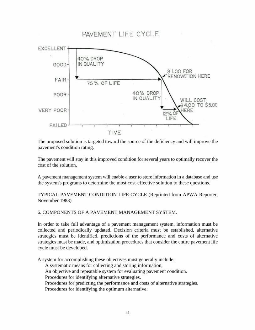
Such a decision is critical in order to avoid higher maintenance and repair (M & R) costsat a later date. Figure 1 illustrates how a pavement generally deteriorates and the relative costof rehabilitation at various times throughout its life. Note that during the first 75 percent ofa pavements' life, it performs relatively well, After that, however, it begins to deterioraterapidly. The number of years a pavement stays in "good" condition depends on how well itis maintained. Numerous studies have shown that the ratio of total annual costs betweenmaintaining a good pavement and periodically rehabilitating a poor pavement is in the orderof 1 to 4 or 5.
Figure 1 also shows that the optimum time for major rehabilitation is just as a pavement'srate of deterioration begins to increase. Maintenance and rehabilitation solutions would bemore easily managed if pavements exhibited a clear sign at this point, but this is not the case.The shape of the deterioration curve, and therefore the optimal maintenance and repairpoints, vary considerably within a pavement network. A pavement experiencing a suddenincrease in operations or aircraft loading will have a tendency to deteriorate more rapidlythan a pavement deteriorating from environmental causes. In addition, there are no obviousvisual signs at this time. A pavement deteriorating from environmental damage may have anumber of cracks that need filling but still be structurally sound. Conversely, this samepavement may be in the early stages of load damage deterioration, which can only bedetected with proper testing.
Since there is no "positive signal" as to when a pavement reaches the 75 percentdeterioration point, we depend on a PMS to help us target our resources to this optimumrehabilitation point. This can be accomplished through the use of a pavement condition ratingsystem, which will predict future conditions and indicate whether the distress is load, orenvironmentally related.
b. cost-effective Solutions.
Information on pavement deterioration, by itself, is not sufficient to answer questionsinvolved in selecting cost-effective maintenance and repair strategies. For example, shoulda pavement be seal coated, recycled, or resurfaced? This type of decision requiresinformation on the cost of various maintenance and repair procedures and their effectiveness.Effectiveness in this case means:
41
The proposed solution is targeted toward the source of the deficiency and will improve thepavement's condition rating.
The pavement will stay in this improved condition for several years to optimally recover thecost of the solution.
A pavement management system will enable a user to store information in a database and usethe system's programs to determine the most cost-effective solution to these questions.
TYPICAL PAVEMENT CONDITION LIFE-CYCLE (Reprinted from APWA Reporter,November 1983)
6. COMPONENTS OF A PAVEMENT MANAGEMENT SYSTEM.
In order to take full advantage of a pavement management system, information must becollected and periodically updated. Decision criteria must be established, alternativestrategies must be identified, predictions of the performance and costs of alternativestrategies must be made, and optimization procedures that consider the entire pavement lifecycle must be developed.
A system for accomplishing these objectives must generally include: A systematic means for collecting and storing information, An objective and repeatable system for evaluating pavement condition. Procedures for identifying alternative strategies. Procedures for predicting the performance and costs of alternative strategies. Procedures for identifying the optimum alternative.
42
A discussion of the essential components of a PMS follows.
a. Data Base. There are several elements critical to making good pavement maintenanceand repair decisions pavement structure, maintenance history, including costs, traffic data,and information on the condition of a pavement. This data can be stored in a system'sdatabase.
(1) Pavement Structure. A key to analyzing problems and designing solutions is aknowledge of when the pavement was originally built, the structural compositions (materialand thickness), and subsequent overlays, rehabilitation, etc, "As built" records should providethis information. If they are not available or if records are suspect, it will be necessary to taketest cores in the existing pavement.
(2) Maintenance History. A history of maintenance performed and its associated costsprovide valuable information on the effectiveness of various maintenance procedures onflexible and rigid pavements. The cost of each maintenance procedure is necessary whenperforming a life cycle cost analysis. (3) Traffic Data. The number of operations and type of aircraft using the pavement arenecessary when analyzing probable causes of deterioration and when consideringrehabilitation procedures,
(4) Pavement Condition. A basic component of any pavement management system is theability to track a pavement's deterioration and determine the cause of the deterioration. Thisrequires an evaluation process that is objective, systematic, and repeatable. A pavementcondition rating system that is based on the quantity, severity, and type of distress is a ratingof the surface condition of a pavement performance with implications of structuralperformance. Condition rating data collected periodically will track the performance of apavement.
b. Alternative Strategies. In order to compare alternative solutions to a particular problem,the system must contain a list of feasible actions related to the pavement condition. Thesealternative strategies should take into consideration such factors as pavement condition, rateof deterioration, causes of distress, previous maintenance, and current and future traffic.
c. Performance and Costs of Alternatives. Based on the results of identifying alternativestrategies, the system must be able to predict the future performance of a pavement for thevarious alternatives and perform an economic analysis to compare the costs of all alternatives(life cycle costing).
d. Optimization. In order to select the alternative that satisfies cost and performanceconstraints, a procedure that evaluates several alternative solutions to a specific set ofconditions is needed.
7. MICRO-PAVER.
43
a. Background. A pavement management system that has been used on airport pavementnetworks at the state and local level is Micro-PAVER. The U.S. Army ConstructionEngineering Research Laboratory under contract to the Federal Aviation Administrationdeveloped this system, which operates on a microcomputer.
The program allows for storage of pavement condition history, nondestructive testing data,and construction and maintenance history, including cost data. This database provides manycapabilities including evaluation of current conditions, prediction of future conditions,identification of maintenance and rehabilitation needs, inspection scheduling, economicanalysis, and budget planning. Micro-PAVER not only evaluates the present condition of thepavement using the pavement condition index (PCI) described in Appendix A of AC150/5380-6, Guidelines and Procedures for Maintenance of Airport Pavements but can alsopredict its future condition. The PCI is a numerical indicator that reflects the structuralintegrity and surface operational condition of a pavement. It is based on an objectivemeasurement of distress type, severity, and quantity. By projecting the rate of deterioration,a life cycle cost analysis can be performed for various maintenance and rehabilitationalternatives. Not only is the best alternative selected but the optimal time of application isalso determined.
b. Management Levels. Once a database has been established, Micro-PAVER can be usedto assist in making pavement management decisions. Managing a pavement systemeffectively requires decision making at two levels:
(1) Network level. At the network level in which decisions are made regarding themanagement of an entire pavement network. For example, at the local level, all thepavements on an airport, and at the state level, all the pavements on each of the airports inthe state system.
(2) Project level. At the project level, decisions are made regarding the selection of themost cost-effective maintenance and rehabilitation alternative for a pavement identified asa candidate for work at the network level.
8. NETWORK LEVEL.
a. In network level management, questions are answered concerning short and long rangebudget needs, the overall condition of the network, both currently and in the future, andidentification of pavements for consideration at the project level.
b. In addition to providing an automated inventory of pavements being managed, Micro-PAVER provides a series of programs, which access the database and produce customizedreports. These reports help the user make decisions regarding inspection scheduling,identification of pavements for rehabilitation, budget forecasting, identification of routinemaintenance projects, evaluation of current condition, and prediction of future condition.
44
c. Condition prediction is used as the basis for developing inspection schedules andidentifying pavements requiring maintenance or rehabilitation. Once pavements requiringfuture work have been identified, a budget for the current year and for several years into thefuture can be developed. By using an agency's prioritization scheme, maintenance policy, andmaintenance and rehabilitation costs and comparing the budget to the actual funds availablefor the current year, a list of potential projects is produced. This list becomes the link withproject level management.
9. PROJECT LEVEL.
In project level management, decisions are made regarding the most cost-effectivemaintenance and rehabilitation alternative for the pavements identified in the networkanalysis. At this level each of these pavements should have a detailed condition survey. Inaddition, nondestructive and/or destructive tests should be made to determine the pavementsload carrying capacity.
Roughness and friction measurements may be useful for project development. Roughnessmeasurements may be useful when there is evidence of roughness, usually in the form offrequent pilot complaints. Roughness measurement is of more value when the pavement isin very good condition with little or no distress.
If reconstruction is imminent, roughness measurements of the existing pavement may not beof any value. Friction measurements, on the other hand, should be made on a periodic basisto measure the textural properties of the pavement and determine the amount of deteriorationthat has occurred. Nondestructive test data, friction measurements, roughness measurements,and drainage information, may all be entered into the database. This information is used toidentify feasible alternatives that can correct existing deficiencies. The various alternativesidentified including no action, are then compared on a life cycle cost basis. The results,combined with budget and management constraints, produce the current year's maintenanceand repair (M & R) program.
10. REPORT GENERATION AND USAGE.
Micro-PAVER can assist in the decision making process through the use of several standardreports. Each report can be customized to include only the pavements and/or conditions ofinterest and can be generated to represent various budget/condition scenarios. The use ofeach report is briefly outlined below.
a. Inventory Report. This report is a listing of all pavements in a network and containsinformation such as surface type, location, area, and pavement function, that is, runway,taxiway, apron.
b. Inspection Scheduling Report. This report allows the user to schedule inspections for thenext 5 years based on a pavements minimum acceptable PCI condition level and rate ofdeterioration.
45
c. PCI Frequency Report. This report provides the user with an indication of overallnetwork condition, based on the PCI scale, for the current or future years. The projectedcondition can be used to assist in planning future maintenance and repair needs and to informmanagement of present and future conditions. Since the PCI extrapolation used presumes nomajor repairs have occurred between the last inspection and prediction dates, the user can seethe impact on the overall network condition of performing no major repairs.
d. Budget Planning Report. This report allows the user to produce 5 year projected budgetsrequired to maintain the pavement network above a user specified condition level. The useris required to input three forms of data; (1) minimum PCI values for each pavement type (2)average unit repair costs based on surface type and PCI ranges, (3) the inflation rate duringthe analysis period. The report predicts for each pavement selected the year in which theminimum PCI will be reached and calculates the cost of repair.
e. Network Maintenance Report. This report uses the agency's maintenance policy, whichis stored in the database and applies it to the distresses identified in the latest PCI survey.This report can be used to estimate both the type and cost of routine maintenance for thedevelopment of an annual work plan.
f. Economic Analysis Report. This report can be used to help select the most cost-effectivealternative for a pavement repair. For each feasible alternative, the user must input initialcosts, periodic maintenance costs, one time future maintenance costs, interest rates, anddiscount rates. The program performs a life cycle cost analysis and provides the user with anequivalent uniform annual cost per square yard. The program allows the user to vary interestrates, repair costs, and timing so that their effect on alternatives can be analyzed.
11. MICRO-PAVER SOFTWARE.
The Micro-PAVER Program can be operated on an IBM compatible personal computerhaving a hard disk with 20 megabytes storage capacity and 640K random access memory(RAM). Version 2.0, or greater, of MS-DOS is the operating system required.
The Micro-PAVER software package, together with a user's guide, may be obtained from adistribution center. Currently, there are three distribution centers, with each centerresponsible for establishing individual fees for distribution and providing updates andcorrections as they become available. The fees vary according to the service provided to theuser (training, implementation assistance, user's group membership, etc.), but range between$300 and $500 per year. Users should contact each center and determine which one will bestsuit their needs. The location of the centers is contained in AC 150/5000-6, Micro-PAVER,Pavement Management System.
Additional information concerning Micro-PAVER is contained in report numberDOT/FAA/PM-87/8, Micro-PAVER, Concept and Development Airport PavementManagement System, dated July 1987.
46
12. OTHER PAVEMENT MANAGEMENT SYSTEMS.
Pavement management systems other than consulting engineer firms that uses Micro-PAVERprovide pavement evaluation and management services. The software programs used bythese firms are not in the public domain and therefore cannot be purchased for use by anindividual or an agency.
13. BENEFITS OF A PAVEMENT MANAGEMENT SYSTEM.
Some of the benefits to be gained from implementation of a PMS include:
a. provides an objective and consistent evaluation of the condition of a network ofpavements.b. provides a systematic and documentable engineering basis for determining maintenanceand rehabilitation needs.c. identifies budget requirements necessary to maintain pavements at various levels ofserviceability.d. provides documentation on the present and future condition or the pavements in anetwork.
e. determines life-cycle costs for various M & R alternatives. f. identifies the impact on the pavement network as a result of performing no major repairs.
Leonard E. MuddDirector, Office of Airport Standards