Embed Size (px)
Citation preview
Thank you for purchasing a Panasonic Hybrid IP-PBX.Please read this manual carefully before using this product and save this manual for future use.
KX-TDA50: PSMPR Software File Version 4.0000 or laterKX-TDA100/KX-TDA200: PMPR Software File Version 3.2000 or laterKX-TDA600: PLMPR Software File Version 3.1000 or later
Document Version: 2007-04
KX-TDA50/KX-TDA100Model KX-TDA200/KX-TDA600
Hybrid IP-PBX
PC Programming Manual

Introduction
About this Programming ManualThe PC Programming Manual is designed to serve as a system programming reference for the Panasonic Hybrid IP-PBX. It explains how to program this PBX using the KX-TDA Maintenance Console software.
The PC Programming Manual is divided into the following sections:
Section 1, OverviewProvides an overview of programming the PBX.
Section 2, KX-TDA Maintenance Console Operating InstructionsServes as reference operating instructions when using the KX-TDA Maintenance Console software to program the PBX.
Section 3, AppendixProvides a list of all related PC programming items for each feature as Feature Programming References.
References Found in the PC Programming Manual
Programming Manual ReferencesRelated sections of the PC Programming Manual are listed for your reference.
Feature Manual ReferencesThe Feature Manual explains what the PBX can do, as well as how to obtain the most of its many features and facilities. Sections from the Feature Manual are listed throughout this manual for your reference.
Installation Manual ReferencesThe Installation Manual provides instructions detailing the installation and maintenance of the PBX. Sections from the Installation Manual are listed throughout this manual for your reference.
Links to Other Pages and ManualsIf you are viewing this manual with a PC, certain items are linked to different sections of this and other Hybrid IP-PBX manuals. Click on a link to jump to that section.
Linked items include:
• Installation Manual References
• PC Programming Manual References
• Feature Manual References
WARNING
Unplug the PBX from the AC outlet if it emits smoke, an abnormal smell or makes unusual noise. These conditions can cause fire or electric shock. Confirm that smoke has stopped and contact an authorized Panasonic Factory Service Center.
2 PC Programming Manual

Trademarks• Microsoft and Windows are either registered trademarks or trademarks of Microsoft Corporation
in the United States and/or other countries.
• Intel and Celeron are trademarks or registered trademarks of Intel Corporation or its subsidiaries in the United States and other countries.
• All other trademarks identified herein are the property of their respective owners.
• Screen shots reprinted with permission from Microsoft Corporation.
NOTES• The contents of this manual apply to PBXs with a certain software version, as indicated on the
cover of this manual. To confirm the software version of your PBX, see How do I confirm the software version of the PBX or installed cards? in 2.6.1 Frequently Asked Questions (FAQ).
• Some optional service cards, PTs, and features are not available in some areas. Additionally, some optional service cards and features are not available for some PBX models. Please consult your certified Panasonic dealer for more information.
• Product specifications are subject to change without notice.In some cases, additional information, including updates to this and other manuals, is included in the KX-TDA Maintenance Console's Information before programming. Install the latest version of Maintenance Console to view this information.
PC Programming Manual 3
Table of Contents
1 Overview.................................................................................................. 91.1 Introduction ....................................................................................................................101.1.1 Introduction ......................................................................................................................101.1.2 Entering Characters .........................................................................................................111.2 PC Programming............................................................................................................121.2.1 Installing and Starting the Maintenance Console.............................................................121.2.2 Password Security............................................................................................................15
2 KX-TDA Maintenance Console Operating Instructions..................... 172.1 Introduction ....................................................................................................................182.1.1 Starting Maintenance Console and Software Modes.......................................................182.1.2 Access Levels ..................................................................................................................202.1.3 Software Interface ............................................................................................................242.1.4 Card Status ......................................................................................................................272.1.5 Display Options ................................................................................................................282.1.6 Extension Number Setting ...............................................................................................282.2 File ...................................................................................................................................302.2.1 File—New.........................................................................................................................302.2.2 File—Open .......................................................................................................................302.2.3 File—Close.......................................................................................................................312.2.4 File—Save........................................................................................................................312.2.5 File—Save As...................................................................................................................312.2.6 File—Exit..........................................................................................................................322.3 Connect...........................................................................................................................332.3.1 Connect—RS-232C .........................................................................................................332.3.2 Connect—USB.................................................................................................................332.3.3 Connect—LAN .................................................................................................................342.3.4 Connect—Modem ............................................................................................................352.3.5 Connect—Profile Setup....................................................................................................362.3.6 Connect—Profile Editor....................................................................................................372.3.7 Connect—Disconnect ......................................................................................................392.4 Tool..................................................................................................................................402.4.1 Tool—SD memory backup ...............................................................................................402.4.2 Tool—NDSS Link Data Clear ...........................................................................................402.4.3 Tool—DXDP All OUS .......................................................................................................402.4.4 Tool—Simplified Voice Message—Delete All Recordings (KX-TDA50 only) ....................402.4.5 Tool—Simplified Voice Message—Check Current Usage (KX-TDA50 only) ....................412.4.6 Tool—Extension List View................................................................................................412.4.7 Tool—Import.....................................................................................................................412.4.8 Tool—Export ....................................................................................................................452.4.9 Tool—Programmer Code Change....................................................................................452.4.10 Tool—Screen Customize—User Level/Administrator Level..............................................462.4.11 Tool—System Data Convert (KX-TDA50/KX-TDA100/KX-TDA200 only).........................462.5 Utility ...............................................................................................................................482.5.1 Utility—Diagnosis .............................................................................................................482.5.2 Utility—File Transfer PC to PBX (SD Card)......................................................................512.5.3 Utility—File Transfer PBX (SD Card) to PC......................................................................56
4 PC Programming Manual

2.5.4 Utility—SD Card File View and Load ............................................................................... 572.5.5 Utility—SD Card File Delete............................................................................................. 582.5.6 Utility—Message File Transfer PC to PBX ....................................................................... 582.5.7 Utility—Message File Transfer PBX to PC ....................................................................... 582.5.8 Utility—Error Log.............................................................................................................. 592.5.9 Utility—T1 Signaling Bit Monitor (KX-TDA100/KX-TDA200/KX-TDA600 only) ................ 602.5.10 Utility—T1 Line Trace (KX-TDA100/KX-TDA200/KX-TDA600 only)................................. 612.5.11 Utility—ISDN/QSIG Protocol Trace .................................................................................. 612.5.12 Utility—Digital Trunk Error Report (KX-TDA100/KX-TDA200/KX-TDA600 only).............. 622.5.13 Utility—IP Extension Statistical Information ..................................................................... 632.5.14 Utility—CS Information..................................................................................................... 632.5.15 Utility—PS Information..................................................................................................... 642.5.16 Utility—Timed Update (KX-TDA100/KX-TDA200/KX-TDA600 only)................................ 652.5.17 Utility—System Reset—Reset by the Command............................................................. 662.5.18 Utility—Flash ROM ID Information................................................................................... 682.6 Help ................................................................................................................................. 692.6.1 Frequently Asked Questions (FAQ).................................................................................. 692.7 [1] Configuration ............................................................................................................ 802.7.1 [1-1] Slot........................................................................................................................... 802.7.2 [1-1] Slot—Summary ....................................................................................................... 842.7.3 [1-1] Slot—MPR Card Property ....................................................................................... 882.7.4 [1-1] Slot—Extension Card Property................................................................................ 892.7.5 [1-1] Slot—Extension Port................................................................................................ 942.7.6 [1-1] Slot—Extension Port—Port Command.................................................................. 1022.7.7 [1-1] Slot—Extension Port—Port Type View .................................................................. 1032.7.8 [1-1] Slot—CSI/F Port (KX-TDA100/KX-TDA200/KX-TDA600 only) .............................. 1042.7.9 [1-1] Slot—CSI/F Port—Port Command (KX-TDA100/KX-TDA200/KX-TDA600 only) .. 1062.7.10 [1-1] Slot—LCO Card Property ...................................................................................... 1072.7.11 [1-1] Slot—LCO Port ...................................................................................................... 1172.7.12 [1-1] Slot—LCO Port—Port Command .......................................................................... 1222.7.13 [1-1] Slot—PRI Card Property (KX-TDA100/KX-TDA200/KX-TDA600 only) ................. 1232.7.14 [1-1] Slot—PRI Port (KX-TDA100/KX-TDA200/KX-TDA600 only) ................................. 1392.7.15 [1-1] Slot—PRI Port—Port Command (KX-TDA100/KX-TDA200/KX-TDA600 only)...... 1612.7.16 [1-1] Slot—T1 Card Property (KX-TDA100/KX-TDA200/KX-TDA600 only) ................... 1622.7.17 [1-1] Slot—T1 Port (KX-TDA100/KX-TDA200/KX-TDA600 only) ................................... 1732.7.18 [1-1] Slot—T1 Port—Channel Command (KX-TDA100/KX-TDA200/KX-TDA600 only) ....... 1822.7.19 [1-1] Slot—IP-GW Card Property................................................................................... 1832.7.20 [1-1] Slot—IP-GW Port................................................................................................... 1852.7.21 [1-1] Slot—IP-GW Port—Port Command....................................................................... 1872.7.22 [1-1] Slot—IP-Extension Card Property ......................................................................... 1882.7.23 [1-1] Slot—IP-Extension Card Property—Common Settings......................................... 1922.7.24 [1-1] Slot—IP-Extension Port ......................................................................................... 1932.7.25 [1-1] Slot—OPB (KX-TDA100/KX-TDA200/KX-TDA600 only) ....................................... 1992.7.26 [1-1] Slot—OPB Card Command (KX-TDA100/KX-TDA200/KX-TDA600 only)............. 2042.7.27 [1-1] Slot—OPB3 Option Card Setup (KX-TDA100/KX-TDA200/KX-TDA600 only) ...... 2062.7.28 [1-1] Slot—CTI-LINK Card Property (KX-TDA100/KX-TDA200/KX-TDA600 only) ........ 2072.7.29 [1-1] Slot—DPH Card Property (KX-TDA50 only).......................................................... 2092.7.30 [1-1] Slot—DPH Port Command (KX-TDA50 only) ........................................................ 2122.7.31 [1-2] Portable Station ..................................................................................................... 2132.7.32 [1-3] Option .................................................................................................................... 217
PC Programming Manual 5

2.7.33 [1-4] Clock Priority (KX-TDA100/KX-TDA200/KX-TDA600) ...........................................2192.8 [2] System .....................................................................................................................2212.8.1 [2-1] Date & Time/Daylight Saving .................................................................................2212.8.2 [2-1] Date & Time/Daylight Saving—Date & Time Setting .............................................2222.8.3 [2-2] Operator & BGM ....................................................................................................2232.8.4 [2-3] Timers & Counters .................................................................................................2252.8.5 [2-4] Week Table ............................................................................................................2472.8.6 [2-4] Week Table—Time Setting.....................................................................................2472.8.7 [2-5] Holiday Table..........................................................................................................2502.8.8 [2-6-1] Numbering Plan—Main.......................................................................................2522.8.9 [2-6-2] Numbering Plan—Quick Dial ..............................................................................2812.8.10 [2-6-3] Numbering Plan—B/NA DND Call Feature.........................................................2832.8.11 [2-7-1] Class of Service—COS Settings ........................................................................2872.8.12 [2-7-2] Class of Service—External Call Block ................................................................3012.8.13 [2-7-3] Class of Service—Internal Call Block .................................................................3022.8.14 [2-8-1] Ring Tone Patterns—Call from CO.....................................................................3032.8.15 [2-8-2] Ring Tone Patterns—Call from Doorphone ........................................................3032.8.16 [2-8-3] Ring Tone Patterns—Call from Others ...............................................................3042.8.17 [2-9] System Options......................................................................................................3062.8.18 [2-10] Extension CID Settings ........................................................................................3362.8.19 [2-11-1] Audio Gain—Paging/MOH ................................................................................3412.8.20 [2-11-2] Audio Gain—Card.............................................................................................3442.9 [3] Group .......................................................................................................................3452.9.1 [3-1-1] Trunk Group—TRG Settings...............................................................................3452.9.2 [3-1-2] Trunk Group—Local Access Priority ...................................................................3522.9.3 [3-2] Extension Group ....................................................................................................3522.9.4 [3-3] Call Pickup Group ..................................................................................................3532.9.5 [3-3] Call Pickup Group—All Setting ..............................................................................3552.9.6 [3-4] Paging Group.........................................................................................................3562.9.7 [3-4] Paging Group—All Setting .....................................................................................3572.9.8 [3-4] Paging Group—External Pager..............................................................................3582.9.9 [3-5-1] Incoming Call Distribution Group—Group Settings ............................................3592.9.10 [3-5-2] Incoming Call Distribution Group—Queuing Time Table ....................................3762.9.11 [3-5-3] Incoming Call Distribution Group—Miscellaneous..............................................3772.9.12 [3-5-4] Incoming Call Distribution Group—Member .......................................................3792.9.13 [3-6] Extension Hunting Group.......................................................................................3812.9.14 [3-6] Extension Hunting Group—Member List ...............................................................3832.9.15 [3-7-1] VM(DPT) Group—System Settings ....................................................................3842.9.16 [3-7-2] VM(DPT) Group—Unit Settings..........................................................................3862.9.17 [3-7-2] VM(DPT) Group—Unit Settings—Member List ..................................................3872.9.18 [3-8-1] VM(DTMF) Group—System Settings .................................................................3902.9.19 [3-8-2] VM(DTMF) Group—Group Settings ...................................................................3992.9.20 [3-8-2] VM(DTMF) Group—Group Settings—Member List ............................................4012.9.21 [3-9] PS Ring Group.......................................................................................................4022.9.22 [3-9] PS Ring Group—Member List ...............................................................................4032.10 [4] Extension.................................................................................................................4052.10.1 [4-1-1] Wired Extension—Extension Settings ................................................................4052.10.2 [4-1-1] Wired Extension—Extension Settings—CLIP Generate.....................................4652.10.3 [4-1-2] Wired Extension—FWD/DND .............................................................................4672.10.4 [4-1-3] Wired Extension—Speed Dial ............................................................................472
6 PC Programming Manual

2.10.5 [4-1-4] Wired Extension—Flexible Button ...................................................................... 4732.10.6 [4-1-4] Wired Extension—Flexible Button—Flexible Button Data Copy ......................... 4902.10.7 [4-1-5] Wired Extension—PF Button.............................................................................. 4902.10.8 [4-1-6] Wired Extension—NDSS Link Data - Send ........................................................ 4912.10.9 [4-1-7] Wired Extension—Simplified Voice Message (KX-TDA50 only)......................... 4922.10.10 [4-2-1] Portable Station—Extension Settings................................................................. 4952.10.11 [4-2-1] Portable Station—Extension Settings—CLIP Generate ..................................... 5282.10.12 [4-2-2] Portable Station—FWD / DND ........................................................................... 5302.10.13 [4-2-3] Portable Station—Flexible Button....................................................................... 5352.10.14 [4-2-3] Portable Station—Flexible Button—Flexible Button Data Copy.......................... 5492.10.15 [4-2-4] Portable Station—NDSS Link Data - Send......................................................... 5492.10.16 [4-2-5] Portable Station—Simplified Voice Message (KX-TDA50 only).......................... 5502.10.17 [4-3] DSS Console—Flexible Button .............................................................................. 5522.10.18 [4-3] DSS Console—Flexible Button—Flexible button Data Copy ................................. 5692.11 [5] Optional Device ...................................................................................................... 5712.11.1 [5-1] Doorphone............................................................................................................. 5712.11.2 [5-2] External Pager ....................................................................................................... 5742.11.3 [5-3-1] Voice Message—DISA System .......................................................................... 5752.11.4 [5-3-2] Voice Message—DISA Message........................................................................ 5832.11.5 [5-3-3] Voice Message—SVM (KX-TDA50 only)............................................................ 5862.11.6 [5-4] External Relay ....................................................................................................... 5902.11.7 [5-5] External Sensor ..................................................................................................... 5942.12 [6] Feature..................................................................................................................... 5982.12.1 [6-1] System Speed Dial ................................................................................................ 5982.12.2 [6-2] Caller ID Modification............................................................................................. 6002.12.3 [6-3] Verification Code.................................................................................................... 6032.12.4 [6-4] Second Dial Tone................................................................................................... 6052.12.5 [6-5] Absent Message .................................................................................................... 6062.12.6 [6-6] Tenant .................................................................................................................... 6072.12.7 [6-7] Dialing Plan............................................................................................................ 6092.12.8 [6-7] Dialing Plan—Auto Assign..................................................................................... 6102.12.9 [6-8] Hotel ...................................................................................................................... 6112.13 [7] TRS .......................................................................................................................... 6142.13.1 [7-1] Denied Code.......................................................................................................... 6142.13.2 [7-2] Exception Code ..................................................................................................... 6142.13.3 [7-3] Special Carrier Code ............................................................................................. 6152.13.4 [7-4] Emergency Dial ..................................................................................................... 6162.13.5 [7-5] Miscellaneous ........................................................................................................ 6162.14 [8] ARS.......................................................................................................................... 6202.14.1 [8-1] System Settings..................................................................................................... 6202.14.2 [8-2] Leading Number .................................................................................................... 6212.14.3 [8-3] Routing Plan Time ................................................................................................. 6222.14.4 [8-3] Routing Plan Time—Time Setting ......................................................................... 6222.14.5 [8-4] Routing Plan Priority .............................................................................................. 6232.14.6 [8-5] Carrier.................................................................................................................... 6242.14.7 [8-6] Leading Number Exception ................................................................................... 6272.14.8 [8-7] Authorization Code for TRG................................................................................... 6282.15 [9] Private Network....................................................................................................... 6292.15.1 [9-1] TIE Table................................................................................................................ 6292.15.2 [9-2] Network Data Transmission ................................................................................... 632
PC Programming Manual 7
2.15.3 [9-3] Network Operator (VoIP)........................................................................................6352.15.4 [9-4] NDSS Key Table ....................................................................................................6372.16 [10] CO & Incoming Call ..............................................................................................6392.16.1 [10-1] CO Line Settings..................................................................................................6392.16.2 [10-2] DIL Table & Port Settings.....................................................................................6412.16.3 [10-3] DID Table (KX-TDA100/KX-TDA200/KX-TDA600 only) .......................................6522.16.4 [10-3] DID Table—Automatic Registration (KX-TDA100/KX-TDA200/KX-TDA600 only) ......6552.16.5 [10-3] DID Table—Name Generate (KX-TDA100/KX-TDA200/KX-TDA600 only) ..........6572.16.6 [10-4] Miscellaneous ......................................................................................................6592.17 [11] Maintenance ..........................................................................................................6612.17.1 [11-1] Main .....................................................................................................................6612.17.2 [11-2] PT Programming Access .....................................................................................6792.17.3 [11-3] Power Failure Transfer (KX-TDA100/KX-TDA200/KX-TDA600 only) ...................680
3 Appendix ............................................................................................. 6833.1 Revision History...........................................................................................................6843.1.1 KX-TDA100/KX-TDA200 PMPR Software File Version 3.2xxx ......................................6843.1.2 KX-TDA50 PSMPR Software File Version 4.0xxx ..........................................................6853.2 Feature Programming References .............................................................................687
8 PC Programming Manual

Section 1
Overview
This section provides an overview of programming the PBX.
PC Programming Manual 9
1.1 Introduction
1.1 Introduction
1.1.1 Introduction
These programming instructions are designed to serve as an overall system programming reference for the Panasonic Hybrid IP-PBX. Each feature in the PBX has default settings that can be changed to customize the PBX to your requirements. These settings control the functions of the PBX, and changing them is referred to as "system programming".Only one person can perform system programming at a time. Any other users trying to enter programming mode will be denied access.
Ways to ProgramThere are two programming methods:
• PC (Personal Computer) ProgrammingAll features and settings of the PBX can be programmed through PC programming with KX-TDA Maintenance Console. Installing and starting the Maintenance Console is described in Section 1.2 PC Programming. Individual PC programming items are described in KX-TDA Maintenance Console Operating Instructions.
• PT (Proprietary Telephone) ProgrammingA subset of the features and settings of the PBX can be programmed using a PT. PT programming is described in the PT Programming Manual.
10 PC Programming Manual

1.1 Introduction
1.1.2 Entering Characters
The characters on a white background below can be used when storing a name, message, password or other text entry data using a PC. The available characters vary according to the model of PBX.
PC Programming Manual 11
1.2 PC Programming
1.2 PC Programming
1.2.1 Installing and Starting the Maintenance Console
System programming, diagnosis and administration can be performed with a PC using the Maintenance Console (KX-TDA50: KX-TDA50 Maintenance Console; KX-TDA100/KX-TDA200: KX-TDA Maintenance Console; KX-TDA600: KX-TDA600 Maintenance Console).This section briefly describes how to install and start the Maintenance Console when the PC and the PBX are connected by USB cable. The screenshots shown in the installation procedure are based on the KX-TDA50 Maintenance Console.
System RequirementsRequired Operating System
• Microsoft Windows 98 SE, Windows Me, Windows 2000, or Windows XP
Minimum Hardware Requirements
• CPU: 300 MHz Intel Celeron microprocessor
• HDD: 100 MB of available hard disk space
• RAM: 128 MB of available RAM
® ®
® ®
12 PC Programming Manual

1.2 PC Programming
Installing the Maintenance Console
Notes• To install or uninstall the software on a PC running Windows 2000 Professional or Windows
XP Professional, you must be logged in as a user in either the "Administrators" or "Power Users" group.
• To connect the PC to the Hybrid IP-PBX via USB, the KX-TDA USB driver must be installed. Follow the instructions of the wizard to install the KX-TDA USB driver. When the Hybrid IP-PBX is first connected to the PC via USB, you may be asked to select the appropriate USB driver. Browse for and select the KX-TDA USB driver that was installed previously.
Starting the KX-TDA Maintenance Console and Assigning the Basic Items (Quick Setup)
When you start the KX-TDA Maintenance Console with the Installer Level Programmer Code and connect to the Hybrid IP-PBX for the first time after initialization (with the factory default setting), Quick Setup will launch automatically. During Quick Setup, you will set up the following basic items:
• Date and Time of the Hybrid IP-PBX. The date and time set to the PC's clock will be used.
• System Password for installer for PC programming.
• Operator and manager settings. Operator extensions for all time modes (day/lunch/break/night) can be assigned.
• Flexible Numbering plan to Type 1 or Type 2. If Type 1 (with ) is selected, " " must prefix all feature numbers (except access numbers) when an extension user wants to use a feature.
• Operator call and Idle Line Access/ARS numbers.
• Remote Maintenance Dial Number. Enter the complete telephone number of the Hybrid IP-PBX. When necessary, this number will be used to access the Hybrid IP-PBX from a remote location for maintenance purposes.
1. Copy the setup file of the KX-TDA Maintenance Console to your PC. (Its icon is shown here, on the left.)
2. Double-click the setup file to run the installer.
3. Follow the on-screen instructions provided by the installation wizard.
1. Connect the PC to the Hybrid IP-PBX with a USB cable.
2. Start Maintenance Console from the Start menu.
3. "Information before programming" appears.
a. Carefully read this important additional information, which includes updates to this and other manuals.
b. Click [OK] to close this window.
PC Programming Manual 13
1.2 PC Programming
Notice
1. During a long programming session, it is highly recommended that you periodically save the system data to the SD Memory Card. If the PBX undergoes a sudden power failure or if the system is reset for some reason, all the system data in RAM will be lost. However, if system data has been saved to the SD Memory Card, it can be easily restored.To save the system data to the SD Memory Card, (1) click the "SD Memory Backup" icon
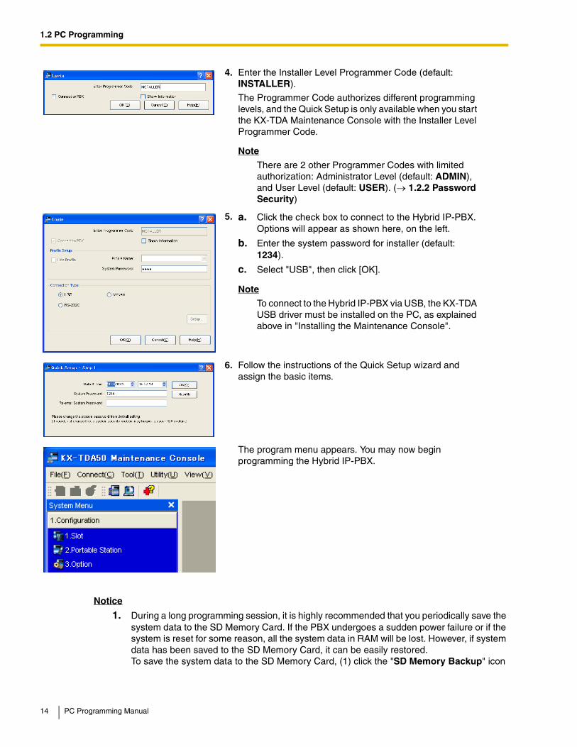
4. Enter the Installer Level Programmer Code (default: INSTALLER).
The Programmer Code authorizes different programming levels, and the Quick Setup is only available when you start the KX-TDA Maintenance Console with the Installer Level Programmer Code.
Note
There are 2 other Programmer Codes with limited authorization: Administrator Level (default: ADMIN), and User Level (default: USER). (→ 1.2.2 Password Security)
5. a. Click the check box to connect to the Hybrid IP-PBX. Options will appear as shown here, on the left.
b. Enter the system password for installer (default: 1234).
c. Select "USB", then click [OK].
Note
To connect to the Hybrid IP-PBX via USB, the KX-TDA USB driver must be installed on the PC, as explained above in "Installing the Maintenance Console".
6. Follow the instructions of the Quick Setup wizard and assign the basic items.
The program menu appears. You may now begin programming the Hybrid IP-PBX.
14 PC Programming Manual

1.2 PC Programming
before resetting the PBX or turning off the power, or (2) exit the Maintenance Console so that the PBX automatically saves the system data.
2. The PC will not perform any shutdown operation, or enter the power-saving system standby mode while the Maintenance Console is connected to the PBX.To perform either of the operations above, first close the connection to the PBX.
CAUTIONDo not remove the SD Memory Card while power is supplied to the Hybrid IP-PBX. Doing so may cause the Hybrid IP-PBX to fail to start when you try to restart the system.
1.2.2 Password Security
To maintain system security, system passwords are required to access certain programming functions of the PBX. By giving different users access to different passwords, it is possible to control the amount of programming that each user is able to perform.The following types of system passwords are available:
The three programmer codes used for PC programming can be set through Maintenance Console, using the 2.4.9 Tool—Programmer Code Change option. For more information about programmer codes, see 2.1.2 Access Levels.
Warning to the Administrator or Installer regarding the system password
1. Please provide all system passwords to the customer.
2. To avoid unauthorized access and possible abuse of the PBX, keep the passwords secret, and inform the customer of the importance of the passwords, and the possible dangers if they become known to others.
3. The PBX has default passwords preset. For security, change these passwords the first time that you program the PBX.
4. Change the passwords periodically.
5. It is strongly recommended that passwords of 10 numbers or characters be used for maximum protection against unauthorized access. For a list of numbers and characters that can be used in system passwords, see 1.1.2 Entering Characters.
6. If a system password is forgotten, it can be found by loading a backup of the system data into a PC, and checking the password using the Maintenance Console software. If you do not have a backup of the system data, you must reset the PBX to its factory defaults and reprogram it. Therefore, we strongly recommend maintaining a backup of the system data.
Password Description Format
System Password for User Used with the user-level programmer code to access user-level PC programming. The installer can specify which system programming settings are available.
4 – 10 characters
System Password for Administrator
Used with the administrator-level programmer code to access administrator-level PC programming. The installer can specify which system programming settings are available.
System Password for Installer
Used with the installer-level programmer code to access installer-level PC programming. All system programming settings are available.
PC Programming Manual 15
1.2 PC Programming
For more information on how to back up the system data, refer to the on-line help of the Maintenance Console.However, as system passwords can be extracted from backup copies of the system data file, do not allow unauthorized access to these files.
16 PC Programming Manual
Section 2
KX-TDA Maintenance Console OperatingInstructions
This section serves as reference operating instructions when using the KX-TDA Maintenance Console software to program the PBX.
PC Programming Manual 17
2.1 Introduction
2.1 Introduction
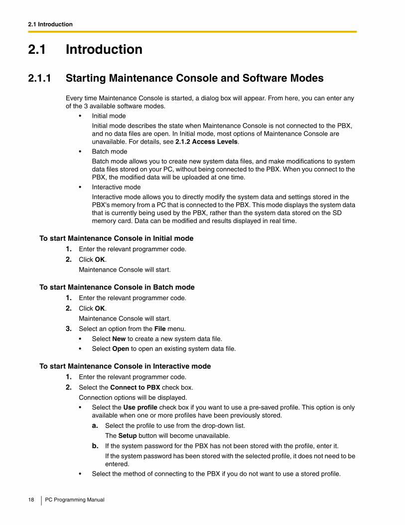
2.1.1 Starting Maintenance Console and Software Modes
Every time Maintenance Console is started, a dialog box will appear. From here, you can enter any of the 3 available software modes.
• Initial mode
Initial mode describes the state when Maintenance Console is not connected to the PBX, and no data files are open. In Initial mode, most options of Maintenance Console are unavailable. For details, see 2.1.2 Access Levels.
• Batch mode
Batch mode allows you to create new system data files, and make modifications to system data files stored on your PC, without being connected to the PBX. When you connect to the PBX, the modified data will be uploaded at one time.
• Interactive mode
Interactive mode allows you to directly modify the system data and settings stored in the PBX's memory from a PC that is connected to the PBX. This mode displays the system data that is currently being used by the PBX, rather than the system data stored on the SD memory card. Data can be modified and results displayed in real time.
To start Maintenance Console in Initial mode1. Enter the relevant programmer code.
2. Click OK.
Maintenance Console will start.
To start Maintenance Console in Batch mode1. Enter the relevant programmer code.
2. Click OK.
Maintenance Console will start.
3. Select an option from the File menu.
• Select New to create a new system data file.
• Select Open to open an existing system data file.
To start Maintenance Console in Interactive mode1. Enter the relevant programmer code.
2. Select the Connect to PBX check box.
Connection options will be displayed.
• Select the Use profile check box if you want to use a pre-saved profile. This option is only available when one or more profiles have been previously stored.
a. Select the profile to use from the drop-down list.
The Setup button will become unavailable.
b. If the system password for the PBX has not been stored with the profile, enter it.
If the system password has been stored with the selected profile, it does not need to be entered.
• Select the method of connecting to the PBX if you do not want to use a stored profile.
18 PC Programming Manual
2.1 Introduction
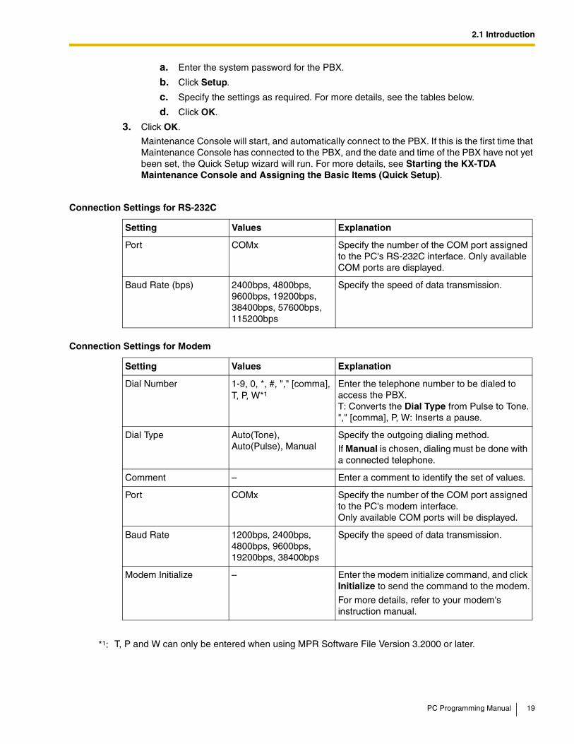
a. Enter the system password for the PBX.
b. Click Setup.
c. Specify the settings as required. For more details, see the tables below.
d. Click OK.
3. Click OK.
Maintenance Console will start, and automatically connect to the PBX. If this is the first time that Maintenance Console has connected to the PBX, and the date and time of the PBX have not yet been set, the Quick Setup wizard will run. For more details, see Starting the KX-TDA Maintenance Console and Assigning the Basic Items (Quick Setup).
Connection Settings for RS-232C
Setting Values Explanation
Port COMx Specify the number of the COM port assigned to the PC's RS-232C interface. Only available COM ports are displayed.
Baud Rate (bps) 2400bps, 4800bps, 9600bps, 19200bps, 38400bps, 57600bps, 115200bps
Specify the speed of data transmission.
Connection Settings for Modem
Setting Values Explanation
Dial Number 1-9, 0, *, #, "," [comma], T, P, W*1
Enter the telephone number to be dialed to access the PBX.T: Converts the Dial Type from Pulse to Tone."," [comma], P, W: Inserts a pause.
Dial Type Auto(Tone), Auto(Pulse), Manual
Specify the outgoing dialing method.
If Manual is chosen, dialing must be done with a connected telephone.
Comment – Enter a comment to identify the set of values.
Port COMx Specify the number of the COM port assigned to the PC's modem interface.Only available COM ports will be displayed.
Baud Rate 1200bps, 2400bps, 4800bps, 9600bps, 19200bps, 38400bps
Specify the speed of data transmission.
Modem Initialize – Enter the modem initialize command, and click Initialize to send the command to the modem.
For more details, refer to your modem's instruction manual.
*1: T, P and W can only be entered when using MPR Software File Version 3.2000 or later.
PC Programming Manual 19

2.1 Introduction
2.1.2 Access Levels
There are three main levels of access to the Maintenance Console: User, Administrator and Installer. Each level has its own Programmer Code, which must be entered to run the Maintenance Console. The allowed format for each programmer code is as follows:
Access to menu options within the Maintenance Console is restricted depending on the Programmer Code, and the current software mode (see 2.1.1 Starting Maintenance Console and Software Modes). When a menu option is limited to certain access levels, this is noted in this manual in the initial description of that menu option, for example:
"This option is only available at Installer level."
If a sentence like this does not appear under the heading, the menu option is available at all levels.
The target users for each access level are as follows:
The options available in each mode and access level are shown below.
The access levels are abbreviated as follows:
U: User; A: Administrator; I: Installer
A check mark indicates that the menu option is available for that access level.
Connection Settings for LAN
Setting Values Explanation
IP Address 1.0.0.0–223.255.255.255
Specify the IP address of the PBX on the LAN. Enter the same IP address that was input in IP Address of 2.7.28 [1-1] Slot—CTI-LINK Card Property (KX-TDA100/KX-TDA200/KX-TDA600 only).
Port Number 10000–65535 Specify the port number used to access the PBX via LAN. Enter the same port number that was input in Maintenance Port Number of 2.7.28 [1-1] Slot—CTI-LINK Card Property (KX-TDA100/KX-TDA200/KX-TDA600 only) or 2.7.19 [1-1] Slot—IP-GW Card Property (KX-TDA50 only).
Item Length
User Level Programmer Code 0 – 16 characters
Administrator Level Programmer Code 4 – 16 characters
Installer Level Programmer Code 4 – 16 characters
Access Level User
User For end users
Administrator For system administrators
Installer For dealers and system installers
20 PC Programming Manual

2.1 Introduction
File
Menu Option Initial Batch Interactive
U A I U A I U A I
New
Open
Close
Save
Save As
Exit
Connect
Menu Option Initial Batch Interactive
U A I U A I U A I
RS-232C
USB
LAN
Modem
Profile Setup
Disconnect
Tool
Menu Option Initial Batch Interactive
U A I U A I U A I
SD memory backup
NDSS Link Data Clear
DXDP All OUS
Simplified Voice Message→Delete All Recordings (KX-TDA50 only)
Simplified Voice Message→Check Current Usage (KX-TDA50 only)
Extension List View
Import→Feature - Speed Dial and Caller ID
PC Programming Manual 21

2.1 Introduction
Import→Incoming Call - DID Table (KX-TDA100/KX-TDA200/KX-TDA600 only)
Import→ARS - Leading Digit
Import→ARS - Except Code
Import→ARS - Routing Plan
Import→Wired Extension
Import→PS Extension
Import→Quick Dial (Basic)
Import→Quick Dial (MEC)
Import→PS Registration (KX-TDA600 only)
Export→Feature - Speed Dial and Caller ID
Export→Incoming Call - DID Table (KX-TDA100/KX-TDA200/KX-TDA600 only)
Export→ARS - Leading Digit
Export→ARS - Except Code
Export→ARS - Routing Plan
Export→Wired Extension
Export→PS Extension
Export→Quick Dial (Basic)
Export→Quick Dial (MEC)
Export→PS registration (KX-TDA600 only)
Programmer Code Change→User Level
Programmer Code Change→Administrator Level
Programmer Code Change→Installer Level
Screen Customize→User Level
Screen Customize→Administrator Level
Tool
Menu Option Initial Batch Interactive
U A I U A I U A I
22 PC Programming Manual

2.1 Introduction
System Data Convert (KX-TDA50/KX-TDA100/KX-TDA200 only)
Utility
Menu Option Initial Batch Interactive
U A I U A I U A I
Diagnosis
File Transfer PC to PBX (SD Card)
File Transfer PBX (SD Card) to PC
SD Card File View and Load
SD Card File Delete
Message File Transfer PC to PBX
Message File Transfer PBX to PC
Error Log
T1 Signaling Bit Monitor (KX-TDA100/KX-TDA200/KX-TDA600 only)
T1 Line Trace (KX-TDA100/KX-TDA200/KX-TDA600 only)
ISDN/QSIG Protocol Trace
Digital Trunk Error Report (KX-TDA100/KX-TDA200/KX-TDA600 only)
IP Extension Statistical Information
CS Information
PS Information
Timed Update (KX-TDA100/KX-TDA200/KX-TDA600 only)
System Reset→Reset by the Command
Flash ROM ID Information
Tool
Menu Option Initial Batch Interactive
U A I U A I U A I
PC Programming Manual 23

2.1 Introduction
2.1.3 Software Interface
This section explains the functions of the various elements of the software interface.
Main WindowThe window of the Maintenance Console software is divided into several areas, as shown below:
View
Menu Option Initial Batch Interactive
U A I U A I U A I
Toolbar
Status Bar
System Menu
Window
Menu Option Initial Batch Interactive
U A I U A I U A I
Cascade
Tile(Horz)
Tile(Vert)
Help
Menu Option Initial Batch Interactive
U A I U A I U A I
Help
Additional Information
About
24 PC Programming Manual

2.1 Introduction
1. Menu BarProvides access to file management and connection options, as well as tools and utilities used in programming the PBX.For details, see Sections 2.2 File to 2.6 Help.
2. Tool BarProvides easy access to commonly used software functions.Two tool bars are provided, as follows:
• FileContains icons for creating, opening, and saving files. For details, see Sections 2.2.1 File—New, 2.2.2 File—Open, and 2.2.4 File—Save.
1 2 3
4 5 6
PC Programming Manual 25
2.1 Introduction
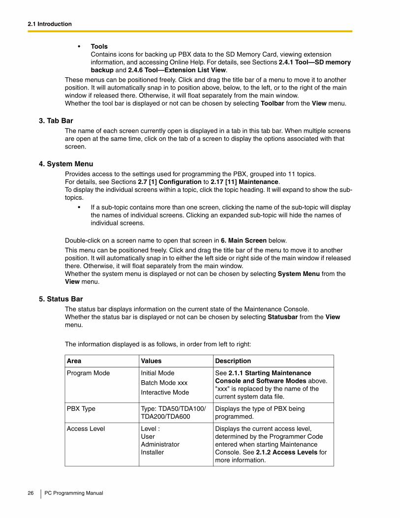
• ToolsContains icons for backing up PBX data to the SD Memory Card, viewing extension information, and accessing Online Help. For details, see Sections 2.4.1 Tool—SD memory backup and 2.4.6 Tool—Extension List View.
These menus can be positioned freely. Click and drag the title bar of a menu to move it to another position. It will automatically snap in to position above, below, to the left, or to the right of the main window if released there. Otherwise, it will float separately from the main window.Whether the tool bar is displayed or not can be chosen by selecting Toolbar from the View menu.
3. Tab BarThe name of each screen currently open is displayed in a tab in this tab bar. When multiple screens are open at the same time, click on the tab of a screen to display the options associated with that screen.
4. System MenuProvides access to the settings used for programming the PBX, grouped into 11 topics.For details, see Sections 2.7 [1] Configuration to 2.17 [11] Maintenance.To display the individual screens within a topic, click the topic heading. It will expand to show the sub-topics.
• If a sub-topic contains more than one screen, clicking the name of the sub-topic will display the names of individual screens. Clicking an expanded sub-topic will hide the names of individual screens.
Double-click on a screen name to open that screen in 6. Main Screen below.
This menu can be positioned freely. Click and drag the title bar of the menu to move it to another position. It will automatically snap in to either the left side or right side of the main window if released there. Otherwise, it will float separately from the main window.Whether the system menu is displayed or not can be chosen by selecting System Menu from the View menu.
5. Status BarThe status bar displays information on the current state of the Maintenance Console.Whether the status bar is displayed or not can be chosen by selecting Statusbar from the View menu.
The information displayed is as follows, in order from left to right:
Area Values Description
Program Mode Initial Mode
Batch Mode xxx
Interactive Mode
See 2.1.1 Starting Maintenance Console and Software Modes above."xxx" is replaced by the name of the current system data file.
PBX Type Type: TDA50/TDA100/ TDA200/TDA600
Displays the type of PBX being programmed.
Access Level Level : UserAdministratorInstaller
Displays the current access level, determined by the Programmer Code entered when starting Maintenance Console. See 2.1.2 Access Levels for more information.
26 PC Programming Manual

2.1 Introduction
6. Main ScreenDisplays the screens selected from 4. System Menu above.For details, see Sections 2.7 [1] Configuration to 2.17 [11] Maintenance.
Standard Buttons and ElementsThere are several standard buttons that are displayed on many screens within the Maintenance Console.
The standard buttons are as follows:
In addition, many screens within the software display a small open folder icon ( ) beside lists of setting items. Clicking this icon will collapse part of the list, allowing other items to be displayed. The
icon will change to a closed folder ( ).Clicking the closed folder icon will expand the list again.
2.1.4 Card Status
Certain tools, utilities and settings require that the target card be set to out-of-service (OUS) or in-service (INS) status before the operation is carried out. Where required, this is noted in the description of each item. Card status changes can only be performed when the software is in Interactive mode (see 2.1.1 Starting Maintenance Console and Software Modes).
• "In service" means that the card is installed correctly in the PBX, and is capable of being used normally.
PBX System Data Version
Versionxxx-xxx Displays the version number of the system software installed to the PBX.
The first 3 digits are the version number, and the last 3 digits are the revision number.
PBX Region Code Regionxxx-xxx Displays the region code assigned to the PBX and Maintenance Console.
The first 3 digits represent the region code assigned to the PBX, and the last 3 digits represent the region code assigned to the Maintenance Console.
Button Function
OK Implements changes and closes the current screen.
Cancel Abandons changes and returns to the previous screen.
Close Keeps any changes implemented, and closes the current screen.
Apply Implements changes and remains on the same screen.
Refresh Implements changes, updates displayed data, and remains on the current screen.
Help Displays the relevant help topic for the current screen.
Area Values Description
PC Programming Manual 27
2.1 Introduction
• "Out of service" means that the card is installed correctly in the PBX, but has been temporarily removed from use. This allows settings to be modified or software to be upgraded.
• "Fault" means that the card is not installed in the PBX correctly, or is not functioning correctly. For more information, see the Installation Manual.
For details about how to change the status of a card, see To change the status (INS/OUS) of a card (Interactive mode only) on screen 2.7.1 [1-1] Slot.
2.1.5 Display Options
The View and Window menus provide options to control the display of items within the Maintenance Console.
• View
– Toolbar: Displays or hides the tool bar of commonly used buttons.
– Statusbar: Displays or hides the bar at the bottom of the Maintenance Console window.
– System Menu: Displays or hides the menu of PBX setting screens.
• Window
– Cascade: When multiple data screens are open, displays all open screens overlapped, with the title bars visible.
– Tile(Horz): When multiple data screens are open, displays all open screens side by side.
– Tile(Vert): When multiple data screens are open, displays all open screens vertically.
2.1.6 Extension Number Setting
Many screens within the Maintenance Console software allow you to select extensions as part of programming various features (for example, as members of a group). These screens use a standard window to make selecting multiple extensions easy, accessed by clicking a button. This section explains how to use this Extension Number Setting window.
To select multiple extension numbers, select the type of extension to display, highlight the extensions you wish to add, then click the Add button. When finished, click OK. Data for the selected extensions will be added to the first free spaces on the original screen.
Extension TypeSelects the types of extension numbers to display in Extension Numbers & Names List. Multiple items can be selected. Items that are not available are shown with a grey checkbox.
DefaultNone selected.
Value RangeWired Extension, Portable Station, VM Group(DPT), VM Group(DTMF), ICD Group, PS Ring Group, OGM(DISA), External Pager, Analog MODEM
28 PC Programming Manual

2.1 Introduction
Extension Numbers & Names ListDisplays all available extensions of the types selected in Extension Type, and names. Click entries to select them, and click the Add button when finished, to add the selected extensions. To deselect an entry, click it again.
DefaultAvailable extensions.
Value RangeMatching extensions
Available ColumnSpecifies which fields in the original form to add extension data to. For example, if both extension numbers and names can be entered in the original form, it is possible to specify that extension name data not be transferred, by deselecting that field here.To select or deselect a field, click its name.
DefaultFirst available field
Value RangeAvailable fields
Selected Extension ListDisplays the extensions that have been selected to be added to member data. To remove an extension from this list, click it to select it and click Delete.
DefaultNot stored.
Value RangeSelected extensions
PC Programming Manual 29
2.2 File
2.2 File
2.2.1 File—New
Creates a new system data file, used to program the PBX in Batch mode. All settings are in their initial or default state.
This option is only available at Installer level.
To upload the file created here to the SD memory card installed in the PBX, see 2.5.2 Utility—File Transfer PC to PBX (SD Card).
Note
Since selecting this option creates a blank system data file, uploading this file to the PBX will overwrite all previous settings. Use only when necessary.
To create a new system data file1. From the File menu, select New.
2. Click the appropriate model number.
3. Select whether an EMEC (KX-TDA600) or MEC (KX-TDA50/KX-TDA100/KX-TDA200) card is installed or not.
4. Click OK.
2.2.2 File—Open
Opens a system data file previously saved on the PC, and enters Batch mode.
When opening a file created with an older version of the Maintenance Console, you will be asked whether you want to convert the data for use with the current version or not. Using the data without converting may result in some data being loaded to an incorrect destination, and is not recommended.
For more details regarding file conversion, see 2.4.11 Tool—System Data Convert (KX-TDA50/KX-TDA100/KX-TDA200 only).
If the file is not supported by the PBX (e.g. a system data file from an incompatible PBX), it will not be opened. The only files that can be opened are files that were created by the Maintenance Console for a supported PBX.
To upload a file opened here to the SD memory card installed in the PBX, see 2.5.2 Utility—File Transfer PC to PBX (SD Card).
To open a system data file1. From the File menu, select Open.
The Open dialog box will be displayed.
2. Navigate to the folder containing the system data file you want to open.
3. Select the file.
4. Click Open.
30 PC Programming Manual

2.2 File
If the file was created with an older version of the Maintenance Console, you will be asked if you want to convert the data.
• Click Yes to convert the data for use with the current version of the Maintenance Console.
Enter a name for the new converted system file.
• Click No to open the file as it is.
2.2.3 File—Close
Closes the system data file that is currently being modified, and returns to Initial mode.
To close a system data file• From the File menu, select Close.
If the system data file has not been saved, a warning message will be displayed, giving you the option to save the file.
• Click Yes to save the file.
• Click No to abandon the changes.
2.2.4 File—Save
Overwrites the previously saved system data file with the system data currently being modified in Batch mode.
To upload a file saved here to the SD memory card installed in the PBX, see 2.5.2 Utility—File Transfer PC to PBX (SD Card).
To save a system data file• From the File menu, select Save.
If the data has never been saved, the Save dialog box will be displayed. For more details, see 2.2.5 File—Save As.
2.2.5 File—Save As
Saves the system data file being modified in Batch mode with the name chosen by the user.
To upload a file saved here to the SD memory card installed in the PBX, see 2.5.2 Utility—File Transfer PC to PBX (SD Card).
To save a system data file with a new name1. From the File menu, select Save As.
2. Navigate to the folder in which you want to save the file.
3. Enter a file name, or select a file to overwrite.
4. Click Save.
If choosing to overwrite another file, a warning message will be displayed.
• Click Yes to overwrite.
• Click No to return to the previous screen.
PC Programming Manual 31

2.2 File
2.2.6 File—Exit
Closes the Maintenance Console.
To exit the Maintenance Console• From the File menu, select Exit.
If the system data file being modified has not been saved, a warning message will be displayed, giving you the option to save the file.
• Click Yes to save the file.
• Click No to abandon the changes.
32 PC Programming Manual
2.3 Connect
2.3 Connect
2.3.1 Connect—RS-232C
Connects to the PBX in Interactive mode through the serial RS-232C interface of the PBX.
This option allows direct entry of connection parameters, for cases where the PC is used to connect to one or just a few PBXs, and an individual profile for each PBX is not necessary. If you connect to multiple PBXs and would prefer to choose from among pre-saved profiles instead, see 2.3.5 Connect—Profile Setup for more details about creating profiles.
To connect to the PBX by RS-232C1. From the Connect menu, select RS-232C.
The Login window will be displayed.
2. Select a connection option.
• Select the Use profile check box if you want to use a pre-saved profile. This option is only available when one or more profiles have been previously stored.
a. Select the profile to use from the drop-down list.
The Setup button will become unavailable.
b. If the system password for the PBX has not been stored with the profile, enter it.
If the system password has been stored with the selected profile, it does not need to be entered.
• Confirm that the RS-232C radio button is selected if you want to enter the parameters manually.
a. Click Setup.
b. Specify the settings as required. For more details, see the table below.
c. Click OK.
3. Click OK.
2.3.2 Connect—USB
Connects to the PBX in Interactive mode through the USB port on the PBX, or a USB port (USB Module) attached to a DPT.
Connection Settings for RS-232C
Setting Values Explanation
Port COMx Specify the number of the COM port assigned to the PC's RS-232C interface. Only available COM ports are displayed.
Baud Rate (bps) 2400bps, 4800bps, 9600bps, 19200bps, 38400bps, 57600bps, 115200bps
Specify the speed of data transmission.
PC Programming Manual 33

2.3 Connect
To connect to the PBX by USB1. From the Connect menu, select USB.
The Login window will be displayed.
2. Select a connection option.
• Select the Use profile check box if you want to use a pre-saved profile.
a. Select the profile to use from the drop-down list.
b. If the system password for the PBX has not been stored with the profile, enter it.
If the system password has been stored with the selected profile, it does not need to be entered.
• Select the USB radio button if you do not want to use a profile.
3. Click OK.
2.3.3 Connect—LAN
Connects to the PBX in Interactive mode through the Local Area Network interface of the PBX.
A CTI-LINK card (KX-TDA100/KX-TDA200/KX-TDA600) or IP-GW4 card (KX-TDA50) must be installed and the IP address of the PBX set to use this feature. For more details, see 2.7.28 [1-1] Slot—CTI-LINK Card Property (KX-TDA100/KX-TDA200/KX-TDA600 only) and 2.7.19 [1-1] Slot—IP-GW Card Property (KX-TDA50 only).This option allows direct entry of connection parameters, for cases where the PC is used to connect to one or just a few PBXs, and an individual profile for each PBX is not necessary. If you connect to multiple PBXs and would prefer to choose from among pre-saved profiles instead, see 2.3.5 Connect—Profile Setup for more details about creating profiles.
To connect to the PBX by LAN1. From the Connect menu, select LAN.
The Login window will be displayed.
2. Select a connection option.
• Select the Use profile check box if you want to use a pre-saved profile.
a. Select the profile to use from the drop-down list.
The Setup button will become unavailable.
b. If the system password for the PBX has not been stored with the profile, enter it.
If the system password has been stored with the selected profile, it does not need to be entered.
• Select the LAN radio button if you want to enter parameters manually.
a. Click Setup.
b. Modify the connection parameters as required. For more details, see the table below.
c. Click OK.
3. Click OK.
34 PC Programming Manual

2.3 Connect
2.3.4 Connect—Modem
Connects to the PBX in Interactive mode through the modem.
To access the PBX remotely using this feature, an RMT card must be installed and the Remote—Analog Remote (Modem) Floating Extension Number assigned in 2.17.1 [11-1] Main.
This option allows direct entry of connection parameters, for cases where the PC is used to connect to one or just a few PBXs, and an individual profile for each PBX is not necessary. If you connect to multiple PBXs and would prefer to choose from among pre-saved profiles instead, see 2.3.5 Connect—Profile Setup for more details about creating profiles.
To connect to the PBX by Modem1. From the Connect menu, select Modem.
The Login window will be displayed.
2. Select a connection option.
• Select the Use profile check box if you want to use a pre-saved profile.
a. Select the profile to use from the drop-down list.
The Setup button will become unavailable.
b. If the system password for the PBX has not been stored with the profile, enter it.
If the system password has been stored with the selected profile, it does not need to be entered.
• Confirm that the Modem radio button is selected if you want to enter parameters manually.
a. Click Setup.
b. Modify the connection parameters as required. For more details, see the table below.
c. Click OK.
3. Click OK.
Connection Settings for LAN
Setting Values Explanation
IP Address 1.0.0.0–223.255.255.255
Specify the IP address of the PBX on the LAN. Enter the same IP address that was input in IP Address of 2.7.28 [1-1] Slot—CTI-LINK Card Property (KX-TDA100/KX-TDA200/KX-TDA600 only).
Port Number 10000–65535 Specify the port number used to access the PBX via LAN. Enter the same port number that was input in Maintenance Port Number of 2.7.28 [1-1] Slot—CTI-LINK Card Property (KX-TDA100/KX-TDA200/KX-TDA600 only) or 2.7.19 [1-1] Slot—IP-GW Card Property (KX-TDA50 only).
PC Programming Manual 35

2.3 Connect
2.3.5 Connect—Profile Setup
Profiles are useful when one PC is used to connect to multiple PBXs. Rather than manually adjusting the connection settings each time a different PBX is accessed, it is possible to store the connection settings for several PBXs. Then, when you wish to connect to a specific PBX, you can simply choose that PBX's profile from the list.
Note that the order of items in this section corresponds to MPR Software File Version 3.2000 or later of the Maintenance Console. If using an earlier version, please refer to the PC Programming Manual that came with that version.
The functions of the buttons on this screen are as follows:
Connection Settings for Modem
Setting Values Description
Dial Number 1-9, 0, *, #, "," [comma], T, P, W*1
Enter the telephone number to be dialed to access the PBX.T: Converts the Dial Type from Pulse to Tone."," [comma], P, W: Inserts a pause.
Dial Type Auto(Tone), Auto(Pulse), Manual
Specify the outgoing dialing method.
If Manual is chosen, dialing must be done with a connected telephone.
Comment – Enter a comment to identify the set of values.
Port COMx Specify the number of the COM port assigned to the PC's modem interface.Only available COM ports will be displayed.
Baud Rate 1200bps, 2400bps, 4800bps, 9600bps, 19200bps, 38400bps
Specify the speed of data transmission.
Modem Initialize – Enter the modem initialize command, and click Initialize to send the command to the modem.
For more details, refer to your modem's instruction manual.
*1: T, P and W can only be entered when using MPR Software File Version 3.2000 or later.
Button Function
New Opens the 2.3.6 Connect—Profile Editor window to create a new profile.
Edit When an existing profile is selected, opens the 2.3.6 Connect—Profile Editor window to modify the parameters of that profile.
Delete When an existing profile is selected, deletes that profile. A confirmation message will be displayed.
Close Closes the current window.
36 PC Programming Manual
2.3 Connect
To create or edit a profile• From the Connect menu, select Profile Setup.
2.3.6 Connect—Profile Editor
Allows the creation and editing of profiles of settings required to connect the PC to the PBX by RS-232C, LAN, modem, or USB.
Note that the order of items in this section corresponds to MPR Software File Version 3.2000 or later of the Maintenance Console. If using an earlier version, please refer to the PC Programming Manual that came with that version.
Note
When a profile is edited and saved with a new name, the original profile is not deleted.
The settings are as follows:
The functions of the buttons on this screen are as follows:
To create or edit a profile1. From the Connect menu, select Profile Setup.
The Profile Setup window (2.3.5 Connect—Profile Setup) will be displayed.
2. Click New or Edit.
The Profile Editor window will be displayed.
3. Enter a name for this profile.
4. Enter the system password used to connect to the PBX.
5. Select the default connection method.
6. Enter the detailed connection method settings as required. See the tables below for more information.
Note that it is possible to select connection methods other than the default method when using this profile to connect to the PBX. For this reason, you can choose to input settings for multiple connection methods in a single profile. Click the tabs to view the settings for each type of connection.
7. Click Save.
Setting Description
Profile Name Enter a name used to identify this set of PBX connection settings. This name must not be the same as another profile name.
System Password Enter the password to log on to the target PBX, if required.
Default Select the default connection method.
Button Function
Save Saves the current profile information.
Cancel Closes the current screen without saving the profile information.
PC Programming Manual 37

2.3 Connect
Connection Settings for RS-232C
Setting Values Explanation
Port COMx Specify the number of the COM port assigned to the PC's RS-232C interface. Only available COM ports are displayed.
Baud Rate (bps) 2400bps, 4800bps, 9600bps, 19200bps, 38400bps, 57600bps, 115200bps
Specify the speed of data transmission.
Connection Settings for Modem
Setting Values Description
Dial Number 1-9, 0, *, #, "," [comma], T, P, W*1
Enter the telephone number to be dialed to access the PBX.T: Converts the Dial Type from Pulse to Tone."," [comma], P, W: Inserts a pause.
Dial Type Auto(Tone), Auto(Pulse), Manual
Specify the outgoing dialing method.
If Manual is chosen, dialing must be done with a connected telephone.
Comment – Enter a comment to identify the set of values.
Port COMx Specify the number of the COM port assigned to the PC's modem interface.Only available COM ports will be displayed.
Baud Rate 1200bps, 2400bps, 4800bps, 9600bps, 19200bps, 38400bps
Specify the speed of data transmission.
Modem Initialize – Enter the modem initialize command, and click Initialize to send the command to the modem.
For more details, refer to your modem's instruction manual.
*1: T, P and W can only be entered when using MPR Software File Version 3.2000 or later.
Connection Settings for LAN
Setting Values Explanation
IP Address 1.0.0.0–223.255.255.255
Specify the IP address of the PBX on the LAN. Enter the same IP address that was input in IP Address of 2.7.28 [1-1] Slot—CTI-LINK Card Property (KX-TDA100/KX-TDA200/KX-TDA600 only).
38 PC Programming Manual
2.3 Connect
2.3.7 Connect—Disconnect
Closes the connection between the Maintenance Console and the PBX. When this option is chosen, system data is automatically backed up from the PBX to the SD memory card (see 2.4.1 Tool—SD memory backup).
To disconnect1. From the Connect menu, select Disconnect.
A confirmation message will be displayed.
2. Click Yes.
Port Number 10000–65535 Specify the port number used to access the PBX via LAN. Enter the same port number that was input in Maintenance Port Number of 2.7.28 [1-1] Slot—CTI-LINK Card Property (KX-TDA100/KX-TDA200/KX-TDA600 only) or 2.7.19 [1-1] Slot—IP-GW Card Property (KX-TDA50 only).
Connection Settings for LAN
Setting Values Explanation
PC Programming Manual 39
2.4 Tool
2.4 Tool
2.4.1 Tool—SD memory backup
Saves system data from the PBX to the SD memory card. Backup begins as soon as this option is chosen.
To back up system data• From the Tool menu, select SD memory backup.
2.4.2 Tool—NDSS Link Data Clear
Clears NDSS Link Data stored in the connected PBX. While this tool clears both monitor extension and monitored extension data, it only clears it at the connected PBX. To clear this data at other PBXs in the network, it is necessary to run this tool at those PBXs.
To clear the NDSS Link Data• From the Tool menu, select NDSS Link Data Clear.
A confirmation screen will be displayed.
• Click Yes to clear the data.
• Click No to keep the data, and close the screen.
2.4.3 Tool—DXDP All OUS
Sets the status of all DXDP extension ports to "OUS" simultaneously.
To set all DXDP ports to OUS.1. From the Tool menu, select DXDP All OUS.
2. Click OK.
2.4.4 Tool—Simplified Voice Message—Delete All Recordings (KX-TDA50 only)
Deletes all voice messages recorded to SVM cards installed in the PBX.
To delete voice messages1. From the Tool menu, point to Simplified Voice Message and select Delete All Recordings.
2. Select the card from which to delete messages.
3. Click OK.
40 PC Programming Manual

2.4 Tool
2.4.5 Tool—Simplified Voice Message—Check Current Usage (KX-TDA50 only)
Displays information on the voice messages stored in SVM cards installed in the PBX. For each message, the type of message and the associated extension are displayed.
To view SVM message status• From the Tool menu, point to Simplified Voice Message and select Check Current Usage.
2.4.6 Tool—Extension List View
Displays a list of all programmed extension numbers and types.
The types that can be displayed are as follows:
To view extension information• From the Tool menu, select Extension List View.
2.4.7 Tool—Import
Allows several types of system data files or tables to be imported.
Except for Speed Dial and Caller ID, this option is only available at Installer level.
The files from which data can be imported are files that were previously saved at this or another PBX using the Export tool (see 2.4.8 Tool—Export), or comma-separated value (CSV) files. Unsupported file types cannot be opened. PS Registration (KX-TDA600 only) files are saved with the extension ".kex" by default.
Type Detail
Intercom Wired Extension
VM Voice Mail
Portable Station Wireless Extension (Portable Station)
ICDG Incoming Call Distribution Group
WG PS Ring Group
VM (DPT) VM (DPT) Group
VM (DTMF) VM (DTMF) Group
Pager External Pager
MODEM Analog Modem
OGM (DISA) DISA
DSS DSS Console
DPT-I/F CS PT-interface CS
SVM SVM Card
PC Programming Manual 41
2.4 Tool
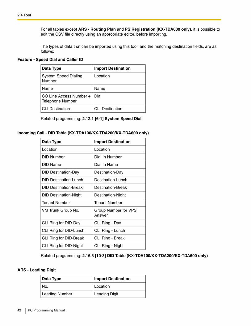
For all tables except ARS - Routing Plan and PS Registration (KX-TDA600 only), it is possible to edit the CSV file directly using an appropriate editor, before importing.
The types of data that can be imported using this tool, and the matching destination fields, are as follows:
Related programming: 2.12.1 [6-1] System Speed Dial
Related programming: 2.16.3 [10-3] DID Table (KX-TDA100/KX-TDA200/KX-TDA600 only)
Feature - Speed Dial and Caller ID
Data Type Import Destination
System Speed Dialing Number
Location
Name Name
CO Line Access Number + Telephone Number
Dial
CLI Destination CLI Destination
Incoming Call - DID Table (KX-TDA100/KX-TDA200/KX-TDA600 only)
Data Type Import Destination
Location Location
DID Number Dial In Number
DID Name Dial In Name
DID Destination-Day Destination-Day
DID Destination-Lunch Destination-Lunch
DID Destination-Break Destination-Break
DID Destination-Night Destination-Night
Tenant Number Tenant Number
VM Trunk Group No. Group Number for VPS Answer
CLI Ring for DID-Day CLI Ring - Day
CLI Ring for DID-Lunch CLI Ring - Lunch
CLI Ring for DID-Break CLI Ring - Break
CLI Ring for DID-Night CLI Ring - Night
ARS - Leading Digit
Data Type Import Destination
No. Location
Leading Number Leading Digit
42 PC Programming Manual

2.4 Tool
Related programming: 2.14.2 [8-2] Leading Number
Related programming: 2.14.7 [8-6] Leading Number Exception
Related programming: 2.14.3 [8-3] Routing Plan Time
Related programming: 2.10.1 [4-1-1] Wired Extension—Extension Settings
Related programming: 2.10.10 [4-2-1] Portable Station—Extension Settings
Additional Number of Digits Additional Dial Digits
Routing Plan Number Route Plan Number
ARS - Except Code
Data Type Import Destination
No. Location
Leading Number Exception Exception Code
ARS - Routing Plan
Data Type Import Destination
(no fields to select) (no fields to select)
Wired Extension
Data Type Import Destination
No. Location (selected automatically)
Extension Number Extension Number (selected automatically)
Extension Name Extension Name (selected automatically)
PS Extension
Data Type Import Destination
No. Location (selected automatically)
Extension Number Extension Number (selected automatically)
Extension Name Extension Name (selected automatically)
ARS - Leading Digit
Data Type Import Destination
PC Programming Manual 43
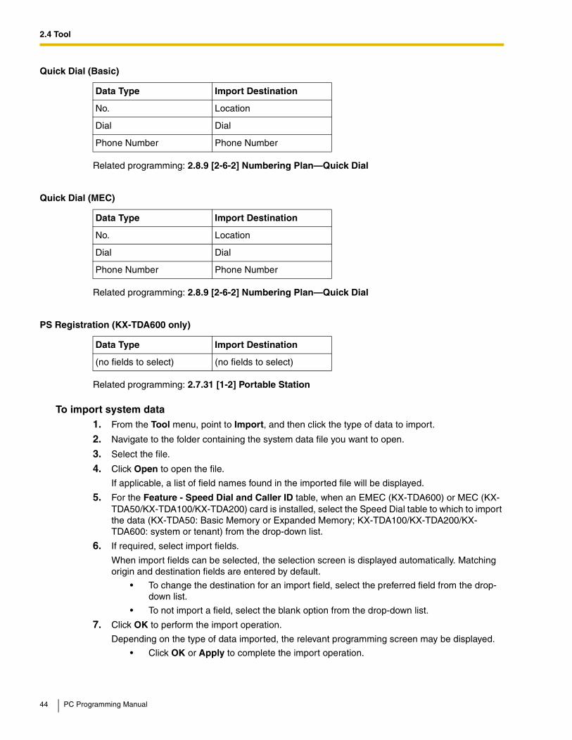
2.4 Tool
Related programming: 2.8.9 [2-6-2] Numbering Plan—Quick Dial
Related programming: 2.8.9 [2-6-2] Numbering Plan—Quick Dial
Related programming: 2.7.31 [1-2] Portable Station
To import system data1. From the Tool menu, point to Import, and then click the type of data to import.
2. Navigate to the folder containing the system data file you want to open.
3. Select the file.
4. Click Open to open the file.
If applicable, a list of field names found in the imported file will be displayed.
5. For the Feature - Speed Dial and Caller ID table, when an EMEC (KX-TDA600) or MEC (KX-TDA50/KX-TDA100/KX-TDA200) card is installed, select the Speed Dial table to which to import the data (KX-TDA50: Basic Memory or Expanded Memory; KX-TDA100/KX-TDA200/KX-TDA600: system or tenant) from the drop-down list.
6. If required, select import fields.
When import fields can be selected, the selection screen is displayed automatically. Matching origin and destination fields are entered by default.
• To change the destination for an import field, select the preferred field from the drop-down list.
• To not import a field, select the blank option from the drop-down list.
7. Click OK to perform the import operation.
Depending on the type of data imported, the relevant programming screen may be displayed.
• Click OK or Apply to complete the import operation.
Quick Dial (Basic)
Data Type Import Destination
No. Location
Dial Dial
Phone Number Phone Number
Quick Dial (MEC)
Data Type Import Destination
No. Location
Dial Dial
Phone Number Phone Number
PS Registration (KX-TDA600 only)
Data Type Import Destination
(no fields to select) (no fields to select)
44 PC Programming Manual

2.4 Tool
If data in a field being imported does not match the required format for the import destination, an error message will be displayed when the import operation is attempted, and the operation will be canceled.
This can occur when, for example, the destination field can only accept numeric data, but the data being imported contains alphabet characters, as the correct fields were not linked together.
2.4.8 Tool—Export
Allows several types of system data to be exported to files. These files can be used with the Import tool (see 2.4.7 Tool—Import) to update another PBX.Except for ARS - Routing Plan and PS Registration (KX-TDA600 only), tables are exported as comma-separated value (CSV) files.
Except for Speed Dial and Caller ID, this option is only available at Installer level.
NoteThe separator used in CSV files created using the Export tool is decided by the unit specified in List Separator, in the Windows Regional Options Control Panel.
To export system data1. From the Tool menu, point to Export, and then click the type of data to export.
2. Navigate to the folder in which you want to save the file.
3. Enter a file name.
4. Click Save to display the Export window.
5. For the Feature - Speed Dial and Caller ID table, when an EMEC (KX-TDA600) or MEC (KX-TDA50/KX-TDA100/KX-TDA200) card is installed, select the Speed Dial table from which to export the data (KX-TDA50: Basic Memory or Expanded Memory; KX-TDA100/KX-TDA200/KX-TDA600: system or tenant) from the drop-down list.
A list of field names that can be exported will be displayed.
6. Click the check box beside the name of each field that you want to export.
7. Click OK.
2.4.9 Tool—Programmer Code Change
Allows you to change the code used to log on to the Maintenance Console at startup.
This option is only available at Installer level.
It is possible to change the codes used for your level and below, but not codes used for higher levels. Only codes that you can change will be displayed in the Programmer Code Change menu. For an explanation of the Programmer Code levels, see 2.1.2 Access Levels.
The current code is displayed when the Programmer Code Change window opens.
The required length of each level's code is as follows:
Access Level Programmer Code Length
User 0 – 16 characters
Administrator 4 – 16 characters
PC Programming Manual 45

2.4 Tool
To change a code1. From the Tool menu, select Programmer Code Change.
2. Enter the new Programmer Code in the first box.
Make sure that the new code is the required length, and contains only ASCII characters.
3. Re-enter the same code in the second box.
4. Click OK to activate the new code.
2.4.10 Tool—Screen Customize—User Level/Administrator Level
Allows you to specify which menu screens, tools and utilities can be accessed in User and Administrator levels.
This option is only available at Installer level.
Selected check boxes will be displayed on the main screen of the Maintenance Console and in the menu bar to users with the level of access being edited.
To modify displayed screens1. From the Tool menu, point to Screen Customize, and then click the access level to modify.
2. Select the items that you want to have displayed.
• Clear the check box beside the names of items you do not want to have displayed.
• Select the check box beside the names of items you want to have displayed.
3. Click OK.
2.4.11 Tool—System Data Convert (KX-TDA50/KX-TDA100/KX-TDA200 only)
Converts system data (DSYS/DSSYS) files created with a previous version of the Maintenance Console for use with the currently loaded version.
This option is only available when the Maintenance Console is in Initial mode.
It is necessary to convert system data to use it with a version of the Maintenance Console other than the version that saved that data. This is because each new version of the Maintenance Console adds new options and settings that are not saved by older versions.
Note
When upgrading from a system without an MEC card installed to a system with an MEC card installed, after converting the system data using this utility, it is necessary to pre-install the MEC card by setting Memory Expansion Card: on the 2.7.3 [1-1] Slot—MPR Card Property screen to PreInstall.
To convert system data1. From the Tool menu, select System Data Convert.
2. In Source File Name, enter the file to convert.
Installer 4 – 16 characters
Access Level Programmer Code Length
46 PC Programming Manual
2.4 Tool
• Enter the path and name of the file in the text field.
• Click the "…" button to navigate to and select the target file.
3. In Destination File Name, enter the desired name for the converted file.
The destination file name or location must be different from the source file name.If another file with the same name already exists in that location, it will be automatically overwritten.
• Enter the path and name of the file in the text field.
If you do not specify a path, the new file will be saved in the same directory as the source file.
• Click the "…" button to navigate to and select the target file.
4. Click OK.
If the convert operation was successful, a message will be displayed.
5. Click OK.
PC Programming Manual 47

2.5 Utility
2.5 Utility
2.5.1 Utility—Diagnosis
Performs diagnostic tests on cards installed in the PBX, to identify the source of problems. There are 2 types of test, Card Test and Pair Port Test (KX-TDA100/KX-TDA200/KX-TDA600 only).
If any of the tests listed here returns the result "NG" ("No Good"), contact your dealer. Test results can be saved as a TXT-format (text) file.
When testing is complete, any cards that were set to OUS status must be returned to INS status if they are to be used again.
Card TestTests the relevant functions of a card to ensure that it is operating correctly. The tests carried out vary according to the type of card being tested.
The tests that are performed on each card are as follows:
A check mark indicates that the test is available for that card.
KX-TDA50
DH
LC
4
DL
C4
DL
C8
SL
C4
SL
C8
IP-E
XT
4
HL
C4
PL
C4
PL
C8
LC
OT
IP-G
W4
EC
HO
8
MS
G2
SV
M2
DP
H4
EX
T-C
ID
Local loop back diagnosis
Card CT Bus diagnosis
DTMF Receive test port
MSG/SVM Card DTMF receive test
EXT-CID path test
48 PC Programming Manual

2.5 Utility
KX-TDA100/KX-TDA200/KX-TDA600
DH
LC
DL
C
SL
C8
SL
C16
/MS
LC
16/E
SL
C16
/EM
SL
C16
/CS
LC
16
CS
IF
LC
OT
/EL
CO
T
T1
PR
I
OP
B
CT
I-L
INK
IP-G
W4
(TD
A04
84)
IP-G
W16
IP-E
XT
16
Local loop back diagnosis
Card CT Bus diagnosis (KX-TDA100/KX-TDA200 only)
DTMF Receive test port
PT loop back diagnosis
Caller ID Card DTMF Sending Out Diagnosis
DSP DTMF generator/receiver diagnosis
DSP DTMF receiver diagnosis
Framer IC alarm signal detection diagnosis
Framer IC error detection diagnosis
CS-INF loop back diagnosis
Super frame synchronization diagnosis
Caller ID card loop back diagnosis
Extension mode setting test
CTI-LINK loop back diagnosis
IP-GW H.323 call simulate diagnosis
LAN loop back diagnosis
PC Programming Manual 49

2.5 Utility
To perform a card test1. From the Utility menu, select Diagnosis.
2. Click on the Status cell of the card to be tested, and set it to "OUS".With the KX-TDA50, to perform the EXT-CID path test, set the status of both the EXT-CID card and the card in slot 1 to "OUS".
3. Click on the cell showing the card type.
A new window will be displayed.
4. Select the Card Test option.
A new window will be displayed.
5. Click OK to perform the test(s).
The error report will be displayed. When all tests are completed, the words "Test End!" will be shown on the last line of the output.
6. Select an option:
• Click Capture if you want to save the displayed information.
1. Enter a file name, or select a file to overwrite.
2. Click Save.
• Click Cancel to return to the Diagnosis screen.
Pair Port Test (KX-TDA100/KX-TDA200/KX-TDA600 only)Tests the combination of an extension port and CO line port to ensure that communication with the CO line port can be carried out successfully.
The pair port test can be carried out using one LCOT or ELCOT card and one DHLC, SLC8, SLC16, MSLC16, ESLC16, EMSLC16 or CSLC16 card.
Note
With the KX-TDA600, the pair of cards to be used for the pair port tests must be installed within the same shelf.
The tests that are performed are as follows:
To perform a pair port test1. From the Utility menu, select Diagnosis.
2. Click on the Status cell of the extension card to be tested, and set it to "OUS".
3. Click on the cell showing the card type.
Line current OFF (Ext—>CO) Line current from extension to CO line turns off.
Line current ON (Ext—>CO) Line current from extension to CO line turns on.
Off hook detection (CO—>Ext) Off-hook generation/detection from CO line to extension
DTMF detection (CO—>Ext) DTMF generation/detection from CO line to extension
DP detection (CO—>Ext) DP generation/detection from CO line to extension
BELL detection (Ext—>CO) BELL generation/detection from extension to CO line
Speech path (Ext—>CO) Speech path from extension to CO line
Speech path (CO—>Ext) Speech path from CO line to extension
50 PC Programming Manual
2.5 Utility
A new window will be displayed.
4. Select the Pair Port Test option.
A new window will be displayed. The card you selected in Step 3 will be shown in the Extension Line Slot No. drop-down list.
5. From the CO Line Slot No. drop-down list, select the slot number of the CO line card you want to test.
6. From the CO Line Port No. drop-down list, select the port number of the CO line you want to test.
7. Click OK.
The error report will be displayed.
8. Select an option:
• Click Capture if you want to save the displayed information.
1. Enter a file name, or select a file to overwrite.
2. Click Save.
• Click Cancel to return to the Diagnosis screen.
Network Loopback Test (KX-TDA100/KX-TDA200/KX-TDA600 only) (MPR Software File Version 3.2000 or later)
Performs a remote loopback test on the PRI23 card.
Notes
• To perform this test, it is necessary to set Loopback Test started by Network (MPR Software File Version 3.2000 or later) in 2.7.14 [1-1] Slot—PRI Port (KX-TDA100/KX-TDA200/KX-TDA600 only) to "Enable".
• The version of the PRI23 card must be 2.000 or later.
To perform a network loopback test1. From the Utility menu, select Diagnosis.
2. Click on the Status cell of the PRI23 card, and set it to "OUS".
3. Click on the cell showing the card type.
A new window will be displayed.
4. Select the Loopback Type option.
A new window will be displayed.
5. Select Point1 or Point2 depending on the type of loopback test you want to perform.
The available selections may vary depending on the hardware version of the card.
6. Click Apply.
Preparation for the test is complete. The test will start automatically.
7. After the test is complete, select Release and click Apply.
8. Click Close to return to the Diagnosis screen.
2.5.2 Utility—File Transfer PC to PBX (SD Card)
Copies PBX system files (program files and data files) from the connected PC to the SD memory card installed in the PBX. Pre-existing files on the SD memory card are overwritten.
This option is only available at Installer level.
PC Programming Manual 51
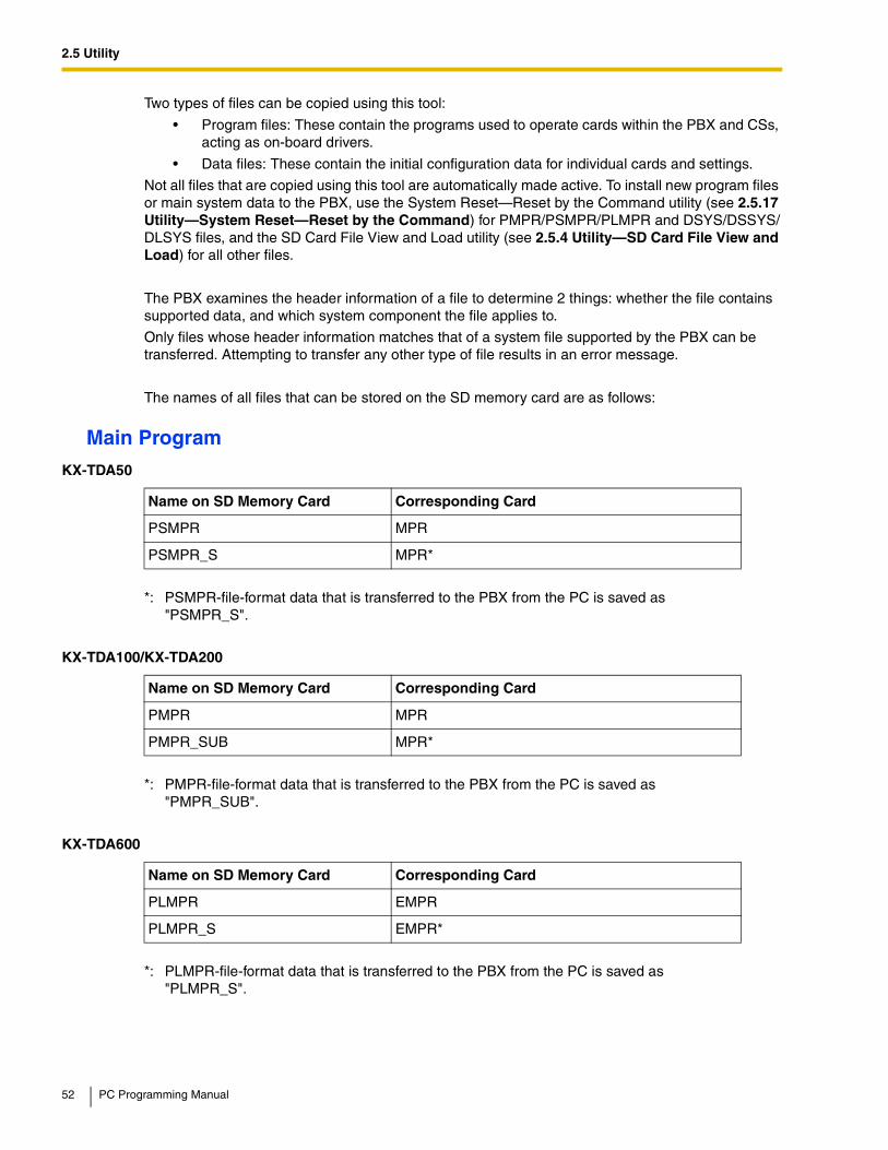
2.5 Utility
Two types of files can be copied using this tool:
• Program files: These contain the programs used to operate cards within the PBX and CSs, acting as on-board drivers.
• Data files: These contain the initial configuration data for individual cards and settings.
Not all files that are copied using this tool are automatically made active. To install new program files or main system data to the PBX, use the System Reset—Reset by the Command utility (see 2.5.17 Utility—System Reset—Reset by the Command) for PMPR/PSMPR/PLMPR and DSYS/DSSYS/DLSYS files, and the SD Card File View and Load utility (see 2.5.4 Utility—SD Card File View and Load) for all other files.
The PBX examines the header information of a file to determine 2 things: whether the file contains supported data, and which system component the file applies to.
Only files whose header information matches that of a system file supported by the PBX can be transferred. Attempting to transfer any other type of file results in an error message.
The names of all files that can be stored on the SD memory card are as follows:
Main Program
KX-TDA50
Name on SD Memory Card Corresponding Card
PSMPR MPR
PSMPR_S MPR*
*: PSMPR-file-format data that is transferred to the PBX from the PC is saved as "PSMPR_S".
KX-TDA100/KX-TDA200
Name on SD Memory Card Corresponding Card
PMPR MPR
PMPR_SUB MPR*
*: PMPR-file-format data that is transferred to the PBX from the PC is saved as "PMPR_SUB".
KX-TDA600
Name on SD Memory Card Corresponding Card
PLMPR EMPR
PLMPR_S EMPR*
*: PLMPR-file-format data that is transferred to the PBX from the PC is saved as "PLMPR_S".
52 PC Programming Manual

2.5 Utility
LPR Program
CS Program
System Data
KX-TDA50
Name on SD Memory Card Corresponding Card
PSVOIPEX IP-EXT4
KX-TDA100/KX-TDA200/KX-TDA600
Name on SD Memory Card Corresponding Card
PCSINF CSIF
PDHLC DHLC8/DLC8/DLC16
PSLC SLC8
PCSLC CSLC16
PT1 T1
PIPGW IP-GW4 (KX-TDA0480)
PIPGWH IP-GW4 (KX-TDA0484)
PIPGW16 IP-GW16
PPRI23 PRI23
POPB3 OPB
PCTILINK CTI-LINK
PIPEXT IP-EXT16
PVOIPEX IP-EXT16
PESLC ESLC16/EMSLC16 (KX-TDA600 only)
PELCOT ELCOT (KX-TDA600 only)
PEECHO EECHO (KX-TDA600 only)
PBUSS BUS-S (KX-TDA600 only)
Name on SD Memory Card Corresponding Unit
PCS24G CS for 2.4 GHz Portable Station (KX-TDA100/KX-TDA200/KX-TDA600 only)
PDCS24G CS for 2.4 GHz Portable Station
KX-TDA50
Name on SD Memory Card Corresponding Card
DSSYS MPR
DSSYS_S MPR*
PC Programming Manual 53
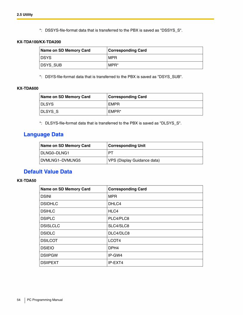
2.5 Utility
Language Data
Default Value Data
*: DSSYS-file-format data that is transferred to the PBX is saved as "DSSYS_S".
KX-TDA100/KX-TDA200
Name on SD Memory Card Corresponding Card
DSYS MPR
DSYS_SUB MPR*
*: DSYS-file-format data that is transferred to the PBX is saved as "DSYS_SUB".
KX-TDA600
Name on SD Memory Card Corresponding Card
DLSYS EMPR
DLSYS_S EMPR*
*: DLSYS-file-format data that is transferred to the PBX is saved as "DLSYS_S".
Name on SD Memory Card Corresponding Unit
DLNG0–DLNG1 PT
DVMLNG1–DVMLNG5 VPS (Display Guidance data)
KX-TDA50
Name on SD Memory Card Corresponding Card
DSINI MPR
DSIDHLC DHLC4
DSIHLC HLC4
DSIPLC PLC4/PLC8
DSISLCLC SLC4/SLC8
DSIDLC DLC4/DLC8
DSILCOT LCOT4
DSIEIO DPH4
DSIIPGW IP-GW4
DSIIPEXT IP-EXT4
54 PC Programming Manual
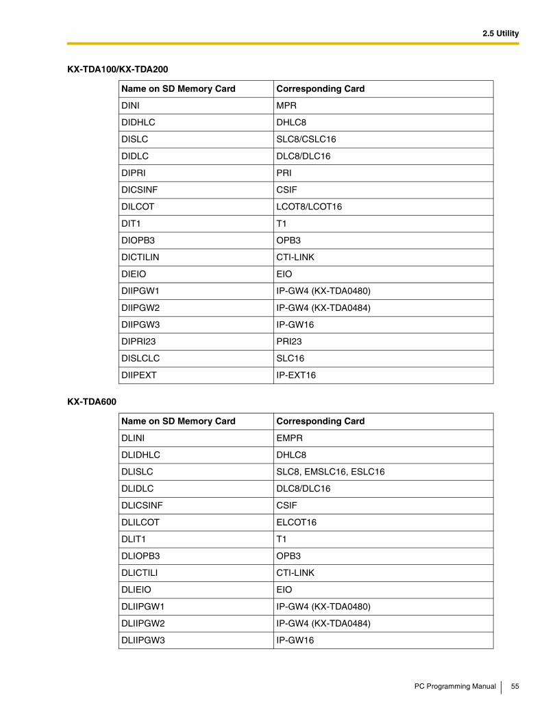
2.5 Utility
KX-TDA100/KX-TDA200
Name on SD Memory Card Corresponding Card
DINI MPR
DIDHLC DHLC8
DISLC SLC8/CSLC16
DIDLC DLC8/DLC16
DIPRI PRI
DICSINF CSIF
DILCOT LCOT8/LCOT16
DIT1 T1
DIOPB3 OPB3
DICTILIN CTI-LINK
DIEIO EIO
DIIPGW1 IP-GW4 (KX-TDA0480)
DIIPGW2 IP-GW4 (KX-TDA0484)
DIIPGW3 IP-GW16
DIPRI23 PRI23
DISLCLC SLC16
DIIPEXT IP-EXT16
KX-TDA600
Name on SD Memory Card Corresponding Card
DLINI EMPR
DLIDHLC DHLC8
DLISLC SLC8, EMSLC16, ESLC16
DLIDLC DLC8/DLC16
DLICSINF CSIF
DLILCOT ELCOT16
DLIT1 T1
DLIOPB3 OPB3
DLICTILI CTI-LINK
DLIEIO EIO
DLIIPGW1 IP-GW4 (KX-TDA0480)
DLIIPGW2 IP-GW4 (KX-TDA0484)
DLIIPGW3 IP-GW16
PC Programming Manual 55
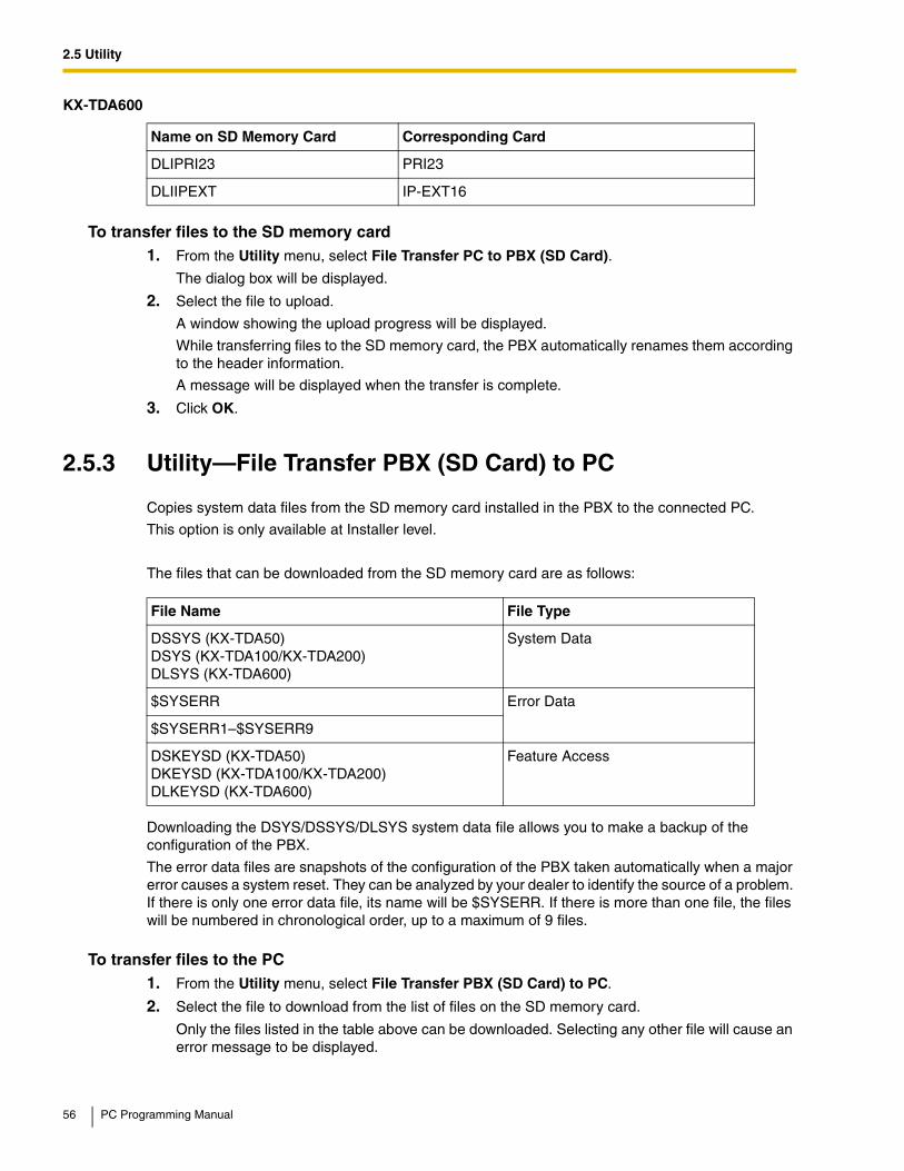
2.5 Utility
To transfer files to the SD memory card1. From the Utility menu, select File Transfer PC to PBX (SD Card).
The dialog box will be displayed.
2. Select the file to upload.
A window showing the upload progress will be displayed.
While transferring files to the SD memory card, the PBX automatically renames them according to the header information.
A message will be displayed when the transfer is complete.
3. Click OK.
2.5.3 Utility—File Transfer PBX (SD Card) to PC
Copies system data files from the SD memory card installed in the PBX to the connected PC.
This option is only available at Installer level.
The files that can be downloaded from the SD memory card are as follows:
Downloading the DSYS/DSSYS/DLSYS system data file allows you to make a backup of the configuration of the PBX.
The error data files are snapshots of the configuration of the PBX taken automatically when a major error causes a system reset. They can be analyzed by your dealer to identify the source of a problem. If there is only one error data file, its name will be $SYSERR. If there is more than one file, the files will be numbered in chronological order, up to a maximum of 9 files.
To transfer files to the PC1. From the Utility menu, select File Transfer PBX (SD Card) to PC.
2. Select the file to download from the list of files on the SD memory card.
Only the files listed in the table above can be downloaded. Selecting any other file will cause an error message to be displayed.
DLIPRI23 PRI23
DLIIPEXT IP-EXT16
File Name File Type
DSSYS (KX-TDA50)DSYS (KX-TDA100/KX-TDA200)DLSYS (KX-TDA600)
System Data
$SYSERR Error Data
$SYSERR1–$SYSERR9
DSKEYSD (KX-TDA50)DKEYSD (KX-TDA100/KX-TDA200)DLKEYSD (KX-TDA600)
Feature Access
KX-TDA600
Name on SD Memory Card Corresponding Card
56 PC Programming Manual

2.5 Utility
3. Click Transfer.
The Save dialog box will be displayed.
4. Navigate to the folder in which you want to save the file.
5. Enter a file name.
6. Click Save.
A window showing the download progress will be displayed.
A message will be displayed when the transfer is complete.
7. Click OK.
2.5.4 Utility—SD Card File View and Load
Displays a list of files on the SD memory card, and allows you to update the programs stored in LPR cards (cards with local processors) (KX-TDA100/KX-TDA200/KX-TDA600 only) and Cell Stations (CSs).
This option is only available at Installer level.
To update the program stored in an LPR card (KX-TDA100/KX-TDA200/KX-TDA600 only), the card must first be set to out of service (OUS). To update the program stored in a CS (T0141/TDA0142), the port of the card (CSIF/DHLC/DLC) that the CS is attached to must be set to OUS, but the card itself must be set to in service (INS). Only cards that are in the correct status will be displayed.
The name, date and time of creation, and size of files are displayed.
To view and load files on the SD memory card1. From the Utility menu, select SD Card File View and Load.
2. Click on the name of the file whose information you want to view.
Only files containing program data (whose filenames start with "P") can be selected.
3. Click Detail.
The Detail screen will be displayed. Header information from the chosen SD memory card file is displayed on the left.
4. From the Card drop-down list on the right, select the card(s) whose software you want to update.
• To update a specific card or port:
• LPR cards (KX-TDA100/KX-TDA200/KX-TDA600 only): select the slot number and card name.
• CSs (T0141/TDA0142): select the slot number and card name, and then select the related CS port from the drop-down list directly below.
• To update all matching cards simultaneously:
• Select "ALL".
5. Click View to update the displayed header information of the selected files.
The file with the higher File Version and File Revision numbers is newer.
6. Click Load to update the file stored on the PBX.
When the update is finished, a message will be displayed.
7. Click OK.
The display will return to the Detail screen.
PC Programming Manual 57
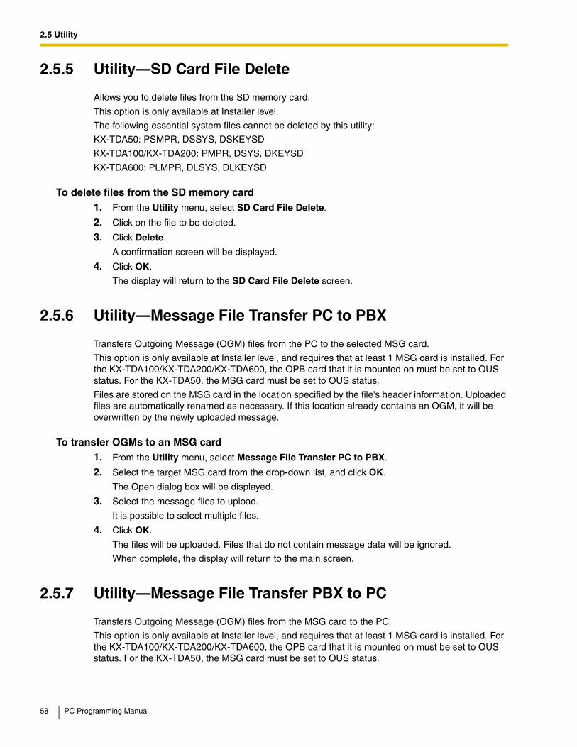
2.5 Utility
2.5.5 Utility—SD Card File Delete
Allows you to delete files from the SD memory card.
This option is only available at Installer level.
The following essential system files cannot be deleted by this utility:
KX-TDA50: PSMPR, DSSYS, DSKEYSD
KX-TDA100/KX-TDA200: PMPR, DSYS, DKEYSD
KX-TDA600: PLMPR, DLSYS, DLKEYSD
To delete files from the SD memory card1. From the Utility menu, select SD Card File Delete.
2. Click on the file to be deleted.
3. Click Delete.
A confirmation screen will be displayed.
4. Click OK.
The display will return to the SD Card File Delete screen.
2.5.6 Utility—Message File Transfer PC to PBX
Transfers Outgoing Message (OGM) files from the PC to the selected MSG card.
This option is only available at Installer level, and requires that at least 1 MSG card is installed. For the KX-TDA100/KX-TDA200/KX-TDA600, the OPB card that it is mounted on must be set to OUS status. For the KX-TDA50, the MSG card must be set to OUS status.
Files are stored on the MSG card in the location specified by the file's header information. Uploaded files are automatically renamed as necessary. If this location already contains an OGM, it will be overwritten by the newly uploaded message.
To transfer OGMs to an MSG card1. From the Utility menu, select Message File Transfer PC to PBX.
2. Select the target MSG card from the drop-down list, and click OK.
The Open dialog box will be displayed.
3. Select the message files to upload.
It is possible to select multiple files.
4. Click OK.
The files will be uploaded. Files that do not contain message data will be ignored.
When complete, the display will return to the main screen.
2.5.7 Utility—Message File Transfer PBX to PC
Transfers Outgoing Message (OGM) files from the MSG card to the PC.
This option is only available at Installer level, and requires that at least 1 MSG card is installed. For the KX-TDA100/KX-TDA200/KX-TDA600, the OPB card that it is mounted on must be set to OUS status. For the KX-TDA50, the MSG card must be set to OUS status.
58 PC Programming Manual

2.5 Utility
To transfer OGMs to the PC1. From the Utility menu, select Message File Transfer PBX to PC.
2. From the upper drop-down list, select the target MSG card.
3. From the lower drop-down list, select the messages to transfer.
• To transfer a certain message, select the number of that message.
• To transfer all messages at once, select "ALL".
The Save dialog box will be displayed.
4. Enter a file name.
5. Click Save.
6. Click OK.
When you choose to transfer all messages, each message is saved as an individual file, with a number appended to the file name corresponding to that message's location on the MSG card.
When complete, the display will return to the main screen.
2.5.8 Utility—Error Log
Collects and displays system error information.
Whenever there is a system failure, the PBX stores the error code generated. The connected PC collects all of these codes, along with other information, and displays an explanatory error message.
The functions of the buttons on this screen are as follows:
The items displayed on screen are as follows:
Button Function
Cancel Closes the Error Log screen without saving.
Capture Saves the currently displayed Error Log information as a text file.
Minor Displays minor errors, which affect only a certain part of system operation.
Major Displays major errors, which affect operation of the whole system, or result in system failure.
Clear Erases the stored error log information from both the screen and the PBX.
Log Information Displays probable causes of the errors and their solutions.
Item Description
Index The ordinal number assigned to an error record in the current log.
Date The date of the error detection.
Time The time of the error detection.
Error Code The 3-digit error code assigned by the PBX.
PC Programming Manual 59
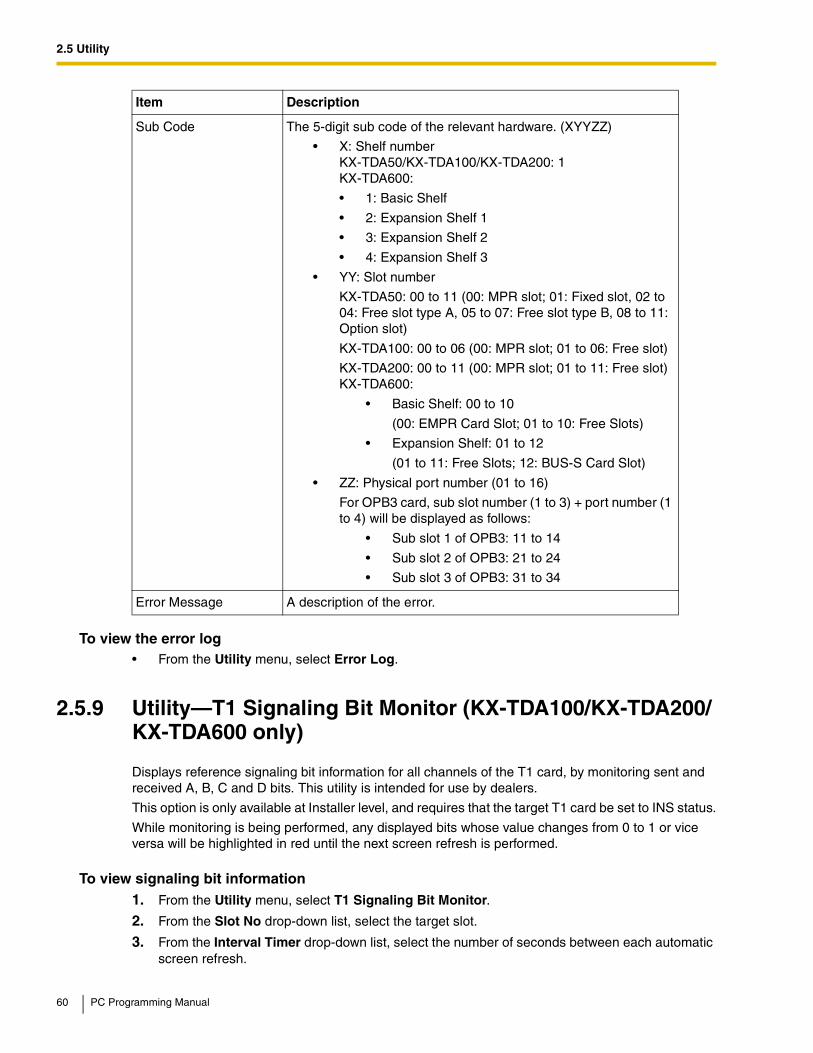
2.5 Utility
To view the error log• From the Utility menu, select Error Log.
2.5.9 Utility—T1 Signaling Bit Monitor (KX-TDA100/KX-TDA200/KX-TDA600 only)
Displays reference signaling bit information for all channels of the T1 card, by monitoring sent and received A, B, C and D bits. This utility is intended for use by dealers.
This option is only available at Installer level, and requires that the target T1 card be set to INS status.
While monitoring is being performed, any displayed bits whose value changes from 0 to 1 or vice versa will be highlighted in red until the next screen refresh is performed.
To view signaling bit information1. From the Utility menu, select T1 Signaling Bit Monitor.
2. From the Slot No drop-down list, select the target slot.
3. From the Interval Timer drop-down list, select the number of seconds between each automatic screen refresh.
Sub Code The 5-digit sub code of the relevant hardware. (XYYZZ)
• X: Shelf numberKX-TDA50/KX-TDA100/KX-TDA200: 1KX-TDA600:
• 1: Basic Shelf
• 2: Expansion Shelf 1
• 3: Expansion Shelf 2
• 4: Expansion Shelf 3
• YY: Slot number
KX-TDA50: 00 to 11 (00: MPR slot; 01: Fixed slot, 02 to 04: Free slot type A, 05 to 07: Free slot type B, 08 to 11: Option slot)
KX-TDA100: 00 to 06 (00: MPR slot; 01 to 06: Free slot)
KX-TDA200: 00 to 11 (00: MPR slot; 01 to 11: Free slot)KX-TDA600:
• Basic Shelf: 00 to 10
(00: EMPR Card Slot; 01 to 10: Free Slots)
• Expansion Shelf: 01 to 12
(01 to 11: Free Slots; 12: BUS-S Card Slot)
• ZZ: Physical port number (01 to 16)
For OPB3 card, sub slot number (1 to 3) + port number (1 to 4) will be displayed as follows:
• Sub slot 1 of OPB3: 11 to 14
• Sub slot 2 of OPB3: 21 to 24
• Sub slot 3 of OPB3: 31 to 34
Error Message A description of the error.
Item Description
60 PC Programming Manual

2.5 Utility
4. Click Start.
Monitoring will be performed and the screen will refresh according to the interval specified.
5. Click Stop to end monitoring.
To refresh the screen at any time while monitoring is stopped, click Refresh.
2.5.10 Utility—T1 Line Trace (KX-TDA100/KX-TDA200/KX-TDA600 only)
Traces the sent and received signaling bits and dial numbers on the specified channel of the T1 line. This utility is intended for use by dealers.
This option is only available at Installer level, and requires that the target T1 card be set to INS status.
To view T1 trace data1. From the Utility menu, select T1 Line Trace.
2. From the Slot No drop-down list, select the target slot.
3. From the CH No drop-down list, select the target channel.
4. Click Start.
Trace information will be displayed. The information is automatically updated whenever the data being monitored changes.
5. Click Stop to end the trace.
6. Select an option:
• Click Capture to save the displayed trace information.
Information is saved as a text-format file.
• Click Clear to erase the information.
2.5.11 Utility—ISDN/QSIG Protocol Trace
This utility collects protocol trace data from PRI or IP-GW cards, and displays it on the PC.
This option is only available at Installer level, and requires that the target PRI or IP-GW card be set to INS status.
Protocol trace data is continually accumulated on ISDN and IP-GW cards, and 3 types of data can be downloaded:
• Real Time Trace (not available when connecting via LAN): Pseudo-real-time data is collected through data polling at one-second intervals. The displayed information is updated beginning when the Start button is clicked.
• Accumulation Trace: Previously accumulated data is retrieved and displayed.
• Error Accumulation Trace: Previously accumulated error data is retrieved and displayed. This trace shows the data snapshot that is taken just before a card resets.
To view trace data1. From the Utility menu, select ISDN/QSIG Protocol Trace.
2. From the Slot No drop-down list, select the target slot.
3. From the Trace Data Type drop-down list, select the type of data to view.
4. Click Start.
PC Programming Manual 61
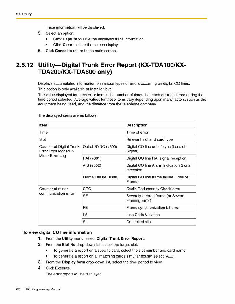
2.5 Utility
Trace information will be displayed.
5. Select an option:
• Click Capture to save the displayed trace information.
• Click Clear to clear the screen display.
6. Click Cancel to return to the main screen.
2.5.12 Utility—Digital Trunk Error Report (KX-TDA100/KX-TDA200/KX-TDA600 only)
Displays accumulated information on various types of errors occurring on digital CO lines.
This option is only available at Installer level.
The value displayed for each error item is the number of times that each error occurred during the time period selected. Average values for these items vary depending upon many factors, such as the equipment being used, and the distance from the telephone company.
The displayed items are as follows:
To view digital CO line information1. From the Utility menu, select Digital Trunk Error Report.
2. From the Slot No drop-down list, select the target slot.
• To generate a report on a specific card, select the slot number and card name.
• To generate a report on all matching cards simultaneously, select "ALL".
3. From the Display form drop-down list, select the time period to view.
4. Click Execute.
The error report will be displayed.
Item Description
Time Time of error
Slot Relevant slot and card type
Counter of Digital Trunk Error Logs logged in Minor Error Log
Out of SYNC (#300) Digital CO line out of sync (Loss of Signal)
RAI (#301) Digital CO line RAI signal reception
AIS (#302) Digital CO line Alarm Indication Signal reception
Frame Failure (#300) Digital CO line frame failure (Loss of Frame)
Counter of minor communication error
CRC Cyclic Redundancy Check error
SF Severely errored frame (or Severe Framing Error)
FE Frame synchronization bit-error
LV Line Code Violation
SL Controlled slip
62 PC Programming Manual

2.5 Utility
2.5.13 Utility—IP Extension Statistical Information
Displays accumulated statistical information on both IP extensions and IP-EXT cards.
The displayed items are as follows:
To view IP extension information1. From the Utility menu, select IP Extension Statistical Information.
2. From the Card Selection drop-down list, select the slot number.
3. Click Execute.
The statistical information will be displayed.
4. Select an option:
• Click Capture if you want to save the displayed information.
1. Enter a file name, or select a file to overwrite.
2. Click Save.
• Click Clear to erase the information and reset the Collection Started Time.
5. Click Cancel to return to the main screen.
2.5.14 Utility—CS Information
Displays information stored by the PBX regarding each Cell Station (CS).
This option is only available at Installer level, and requires that the target CSIF, DHLC or DLC card be set to INS status.
The displayed items are as follows:
Item Description
Collection Started Time Date and time the port was last reset.
Port Number of the port.
RTP Receive Packet Counter Total number of packets received.
RTP Receive Lost Packet Counter Total number of packets lost.
RTP Receive Abandoned Packet Counter Total number of packets abandoned.
RTP Arrive Packet Interval (MAX.) [ms] Maximum time taken for a packet to arrive.
RTP Arrive Packet Interval (MIN.) [ms] Minimum time taken for a packet to arrive.
Item Description
Shelf-Slot Number of the slot (for KX-TDA600, shelf and slot)
Port Number of the port
CS Name Name of the attached CS
PC Programming Manual 63

2.5 Utility
To view CS information1. From the Utility menu, select CS Information.
2. From the Target CSI/F Slot No drop-down list, select the target slot.
• To display information on a single card, select the slot number and name of that card.
• To display information on all matching cards, select "ALL".
3. From the Interval Timer drop-down list, select the number of seconds between each automatic screen refresh.
4. Click Start to begin monitoring.
Monitoring will be performed and the screen will refresh according to the interval specified.
To refresh the screen manually at any time, click Refresh.
5. Click Stop to end monitoring.
2.5.15 Utility—PS Information
Displays Portable Station (PS) registration information, including the associated Cell Station (CS).
This option is only available at Installer level.
The displayed items are as follows:
Status Service status of the attached CS: INS, OUS, or FAULT.
If the status is FAULT, subsequent data items for that port will be left blank.
Version Version number of the program file stored in the CS
Revision Revision number of the program file stored in the CS
CSID 12-digit ID number of the CS
Path Number of the wireless extension currently using each path. In the case of a group, several extensions may be using the same floating extension number.
When an extension number is not registered, the display shows "OFF". PSs can use up to 3 paths (KX-TDA100/KX-TDA200/KX-TDA600) or 2 paths (KX-TDA50).
Group Call Number of PSs registered to the attached CS that are members of a PS Ring Group.
Item Description
PS No. PS location number.
Only registered PSs will be displayed.
Extension Number Extension number of the PS.
Location—Slot Slot number of the CS that the PS is registered with.
Location—Port Port number of the CS that the PS is registered with.
Item Description
64 PC Programming Manual

2.5 Utility
To view PS information1. From the Utility menu, select PS Information.
2. Click Refresh.
2.5.16 Utility—Timed Update (KX-TDA100/KX-TDA200/KX-TDA600 only)
Updates programs in the LPR cards (optional service cards with local processors) by comparing them with files found on the SD memory card on a preset schedule, and downloading newer files to the cards.
This option is only available at Installer level.
It is recommended to set the timed update to take place during the least active time period, for example late at night.
Cards are automatically set to OUS status during an update, and returned to INS status when the update is complete.
This utility does not apply to CS programs. These must be updated manually using the SD Card File View and Load utility (see 2.5.4 Utility—SD Card File View and Load).
When this utility has been set, all commands that would affect the status of cards are prevented from operating.
The list of these commands is as follows:
• Card status change (INS/OUS)
• Diagnosis commands
• Card installation
• Card deletion
• Remote reset
• LPR program download requests
• Signaling Bit Monitor requests (T1)
• Line trace start requests (T1)
• ISDN/QSIG Protocol Data Trace start requests
• Time setting
• CS program download requests
• File deletion
When a function other than those listed above, that cannot be performed while Timed Update has been set, is selected, an error message will be displayed.
To turn this utility on:1. From the Utility menu, select Timed Update.
2. Select the Set option.
The time setting box will become available.
3. Enter the desired time using the number keys.
Click in the hour or minute field and use the up and down arrows to adjust the displayed time in increments of one unit.
4. Click Apply.
PC Programming Manual 65

2.5 Utility
A message box will be displayed.
5. Click OK.
To turn this utility off:1. From the Utility menu, select Timed Update.
2. Select the Off (Cancel) option.
3. Click Apply.
A message box will be displayed.
4. Click OK.
2.5.17 Utility—System Reset—Reset by the Command
Updates the main system program and data files stored within the PBX using files taken from the SD memory card, and resets the connected PBX.
This option is only available at Installer level.
2 copies of each of the main system files can be stored on the SD memory card. The names of these files are as follows:
KX-TDA50
File Name Description
DSSYS Main system data file. Contains all of the current configuration data for the PBX.
DSSYS_S Backup main system data file
PSMPR PBX program file. Contains the software to run the MPR board of the PBX.
PSMPR_S Backup PBX program file
KX-TDA100/KX-TDA200
File Name Description
DSYS Main system data file. Contains all of the current configuration data for the PBX.
DSYS_SUB Backup main system data file
PMPR PBX program file. Contains the software to run the MPR board of the PBX.
PMPR_SUB Backup PBX program file
KX-TDA600
File Name Description
DLSYS Main system data file. Contains all of the current configuration data for the PBX.
DLSYS_S Backup main system data file
66 PC Programming Manual

2.5 Utility
When new DSYS/DSSYS/DLSYS and PMPR/PSMPR/PLMPR files are transferred from a connected PC to the SD memory card using the File Transfer PC to PBX (SD Card) utility (see 2.5.2 Utility—File Transfer PC to PBX (SD Card)), they are stored as the backup files. To use these files on the PBX, it is necessary to first swap them with the currently active files on the SD memory card.
Requirements
• This utility only functions on PBXs version 1.005 and later.
• On earlier versions, the reset request confirmation screen will be displayed, and files will not be updated.
To update system files and reset the PBX1. From the Utility menu, point to System Reset and then click Reset by the Command.
2. Choose whether to back up current system data or not.
• Click SD Backup to back up the current system data to the SD memory card before proceeding.
Select this if you intend to use the current system data unchanged after reset.
• Click Skip to continue without backing up.
Select this if you intend to replace the current system data with data that was uploaded from the PC.
The second screen will be displayed. A list of matching files found on the SD memory card, with dates and times, is shown at the top.
3. Select whether to replace the DSYS/DSSYS/DLSYS and PMPR/PSMPR/PLMPR files or not.
When no backup file is found, the corresponding options are not available.
4. Click OK.
A confirmation screen will be displayed.
5. Select an option:
• Click OK to reset the PBX.
If OK is clicked, a final confirmation screen will be displayed.
• Click Cancel to return to the main screen without copying files.
6. Click OK to reset the PBX, or Cancel to return to the main screen without copying files.
If the reset command was not carried out correctly, an error message will be displayed, and you will be returned to the main screen.
After resetting the PBX with this command, it is necessary to reconnect to the PBX to continue programming.
PLMPR PBX program file. Contains the software to run the EMPR board of the PBX.
PLMPR_S Backup PBX program file
KX-TDA600
File Name Description
PC Programming Manual 67

2.5 Utility
2.5.18 Utility—Flash ROM ID Information
Displays the Flash ROM ID number pre-assigned to the PBX, used for PBX installation management.
To view the Flash ROM ID• From the Utility menu, click Flash ROM ID Information.
68 PC Programming Manual

2.6 Help
2.6 Help
2.6.1 Frequently Asked Questions (FAQ)
This section provides answers to some common questions about using the Maintenance Console software to program the PBX. The information is divided into the following topics:
Connection
Title Description
Connection Connecting to the PBX using Maintenance Console.
Maintenance Console Software Using the Maintenance Console software.
Card Status Changing the status (INS/OUS) of cards.
Portable Stations Setting up portable stations, including registration and deregistration.
Numbering Changing the numbering plan for the PBX, or numbers of individualextensions or features.
Saving Modified Data Safely saving PBX data edited with Maintenance Console.
Setting Features Setting up individual features.
Q The Maintenance Console cannot connect to the PBX via RS-232C cable.A • Is the cable firmly connected to both the PC and the PBX?
• Is the serial port that the PC uses correctly specified?
• Is the baud rate correct?The default setting, and a safe rate, is 19 200 bps.
• Is the password correct?
• Is the Maintenance Console not connected to the PBX by another connection method?
Q The Maintenance Console cannot connect to the PBX via USB.A • Is the USB cable firmly connected to both the PC and the PBX?
• Is the USB driver on the PC running?To confirm, open the Windows Device Manager, and look for "Panasonic KX-TDA USB Main Unit driver" in the USB Controllers section. If it is not present, re-install the USB driver.
• Is the password correct?
• Is the Maintenance Console not connected to the PBX by another connection method?
Q The Maintenance Console cannot connect to the PBX via LAN.A • Is the PC connected to the LAN?
• Have the IP address and port number of the PBX been set correctly? For more details, see 2.7.28 [1-1] Slot—CTI-LINK Card Property (KX-TDA100/KX-TDA200/KX-TDA600 only).
• Is the password correct?
• Is the Maintenance Console not connected to the PBX by another connection method?
PC Programming Manual 69

2.6 Help
Maintenance Console Software
Card Status
Q The Maintenance Console cannot connect to the PBX via modem.A • Is the dial number of the modem correct? For more details, see 2.17.1 [11-1] Main.
• Has a modem been installed to the PBX?
• Are the modem settings of the PBX and Maintenance Console correct? For more details, see 2.17.1 [11-1] Main.
• Is the password correct?
• Is the Maintenance Console not connected to the PBX by another connection method?
Q Can I perform initial setup of the PBX without being connected to the PBX?A • Yes. This is possible in Batch mode.
Create a new system data file using 2.2.1 File—New, edit settings as required, and then upload this file to the PBX later (see 2.5.2 Utility—File Transfer PC to PBX (SD Card)).
Q How do I confirm the software version of the PBX or installed cards?A • From 2.7.1 [1-1] Slot, click Summary. Summary information, including software
versions, is displayed for all cards installed in the PBX.
Q Not all of the characters of a setting can be displayed because the column is too narrow.
A • Move the mouse to the line between the names of 2 setting items, at the top of the table. The pointer will change to a double arrow. Click and drag the line to the right until all characters are displayed.
Q The status of a new card will not change to "INS".A • With the new card installed, does the total number of extensions or CO lines exceed the
maximum supported by the PBX?
• Is the type of card installed in the slot different from the card type set as "Pre-install" for that slot? Confirm that the correct card is installed in the slot.
• Is the card firmly and fully installed in the slot? Confirm that the card is installed correctly in the slot.
• Confirm that the card is not damaged.
Q I want to set the status of only 1 port of the IP-GW4 card to "OUS".A • This cannot be done, since the IP-GW4 card requires both channels of a port to be set
to "OUS"/"INS" together.
Q I cannot change an LCO port to INS status.
70 PC Programming Manual

2.6 Help
Portable Stations
A • Is the card installed in the appropriate slot?
• Is the card installed in the correct slot, but not functioning correctly?Check the condition of the card.
• Is the card itself in INS status?Set it to INS status.
• Is a CO line line connected to the appropriate port?
• Is the port in FAULT status, even though a CO line is connected?Run diagnosis on the relevant slot.
Q How do I prevent newly installed cards automatically being changed to "INS"?A • Change New Card Installation—Card Status for any Card in 2.7.32 [1-3] Option from
"In Service (INS)" to "Out of Service (OUS)".
Q I cannot register Portable Stations using the method described in Portable Station [1-2].
A • Is the status of the CSIF, DHLC or DLC card set to "INS"?
• Is a CS connected to the CSIF, DHLC or DLC card? If not, connect one.
• Do the PINs (Personal Identification Numbers) of the PBX and the Portable Station match? Confirm that they are the same.
• Is the Portable Station within transmission range of the CS?
• Has the Portable Station previously been registered at another location?It is not possible to register a Portable Station at 2 locations, so use the Forced De-registration option to delete the previous registration.
Q I cannot delete the extension number of a Portable Station.A • First, de-register the Portable Station itself, and then delete the extension number.
Q I cannot de-register a Portable Station.A • Is the Portable Station turned on? If not, turn it on.
• Is the Portable Station within transmission range of the CS? If not, move it closer to the CS and try the de-registration operation again.
Q The Portable Station I want to de-register is broken, and will not turn on, or is not available, or the registration information was deleted first from the Portable Station, so it cannot be de-registered.
A • The Portable Station can be forcibly de-registered by the following the procedure shown in Forced De-registration of 2.7.31 [1-2] Portable Station.
Q I changed the extension number of a Portable Station, but the display of the Portable Station still shows the old extension number.
A • Turn the Portable Station off and back on again, to force it to re-register its location.
Q I changed the FCO of a Portable Station, but the display of the Portable Station still shows the old FCO.
A • Turn the Portable Station off and back on again, to force it to re-register its location.
PC Programming Manual 71

2.6 Help
Numbering
Q If I delete the extension number of a Portable Station, and then turn the Portable Station off and back on again, it does not function correctly.
A • Do not delete the extension number of the Portable Station, as this information is necessary for it to operate.
Q How do I change the extension number of a wired extension?A • Change the extension number of the target port to the new number, and click Apply.
Next, set the port to OUS status, and then back to INS status.
Q I changed the extension number of a wired extension while the extension was engaged in a call, but the display still shows the previous extension number.
A • The extension number will not change while the extension is in use. When the conversation is finished, set the port to OUS status, and then back to INS status.
Q How do I change the extension numbering plan from 3-digit numbers to 4-digit numbers?
A • Perform the following steps:
1. Open the 2.8.8 [2-6-1] Numbering Plan—Main screen.
2. Enter a 2-digit number in Leading Number, or change No. of Additional Digits from "x" to "xx".For more details, see What is the procedure to modify the Numbering Plan?.
Q How do I set a 3-digit numbering plan?A • There are 2 methods of creating a 3-digit numbering plan, using 2.8.8 [2-6-1]
Numbering Plan—Main:
1. Set the leading number to be 2 digits, with one additional digit. This method allows a maximum of 10 extensions.
Example: Leading Number = 10; No. of Additional Digits = x
In this example, extension numbers 100 to 109 can be used.
2. Set the leading number to be one digit, with 2 additional digits. This method allows a maximum of 100 extensions.
Example: Leading Number = 1; No. of Additional Digits = xx
In this example, extension numbers 100 to 199 can be used.
For more details, see What is the procedure to modify the Numbering Plan?.
Q What is the procedure to modify the Numbering Plan?
72 PC Programming Manual

2.6 Help
A • Perform the following steps:
1. Confirm that the Numbering Plan you will change is not currently being used by any extensions (see 2.4.6 Tool—Extension List View).
If it is being used by extensions, temporarily change the extension numbers of those extensions to that of another numbering plan, or delete the extension number (see 2.10.1 [4-1-1] Wired Extension—Extension Settings and 2.10.10 [4-2-1] Portable Station—Extension Settings).
2. Clear the Leading Number cell.
3. Click Apply.
4. Modify the No. of Additional Digits cell as required.
5. Click Apply.
6. Enter the desired value in the Leading Number cell.
7. Click Apply.
8. Set all extension ports to OUS status.
9. On the relevant screens, set the extension numbers of extensions to the desired values.
10. Set all extension ports back to INS status.
Q When modifying the Numbering Plan, I cannot change the Leading Number.A • It is not possible to use the same Leading Number for 2 extension blocks, or to use a
number that could possibly overlap with another Leading Number.So, for example, if "2" is already set as a Leading Number it is not possible to set "21" as another Leading Number because of the possible overlap of extension numbers.The number you are trying to store cannot be used if it is already being used by:
• A feature number
• Another extension block
• A Dial setting (see 2.15.1 [9-1] TIE Table)
• Quick Dialing (see 2.8.9 [2-6-2] Numbering Plan—Quick Dial)In any of these cases, choose another number.
Q When modifying the Numbering Plan, how do I set a 1-digit extension number?A • Perform the following steps:
1. Clear the Leading Number cell.
2. Click Apply.
3. Set No. of Additional Digits to "None".
4. Click Apply.
5. Enter the desired value in the Leading Number cell.
6. Click Apply.
7. Set all extension ports to OUS status.
8. On the relevant screens, set the extension numbers of extensions to the desired values.
9. Set all extension ports back to INS status.
Q How do I change a feature number?
PC Programming Manual 73

2.6 Help
Saving Modified Data
A • Perform the following steps:
1. Open the 2.8.8 [2-6-1] Numbering Plan—Main screen.
2. Change the value in the Dial cell of the desired feature.
3. Click Apply.
Q I cannot change a feature number.A • It is not possible to use the same number for 2 items.
The number you are trying to store cannot be used if it is already being used by:
• A feature number
• An extension
• A Dial setting (see 2.15.1 [9-1] TIE Table)
• Quick Dialing (see 2.8.9 [2-6-2] Numbering Plan—Quick Dial)
In any of these cases, choose another number.
Q How do I change the code used to access another PBX?A • Perform the following steps:
1. Open the 2.8.8 [2-6-1] Numbering Plan—Main screen.
2. Select the Other PBX Extension tab.
3. Change the value in the Dial cell of the desired feature.
4. Click Apply.
Q I cannot change an Other PBX Extension code.A • It is not possible to use the same number for 2 items.
The number you are trying to store cannot be used if it is already being used by:
• A feature number
• An extension
• A Dial setting (see 2.15.1 [9-1] TIE Table)
• Quick Dialing (see 2.8.9 [2-6-2] Numbering Plan—Quick Dial)
In any of these cases, choose another number.
Q I cannot change a feature number on the B/NA DND Call Feature screen.A • The number you are trying to store is already being used by another call feature.
Please choose a different number.
Q How do I prevent extension numbers being automatically assigned to a newly installed card?
A • Change New Card Installation—Automatic Extension Number Set for Extension Card in the 2.7.32 [1-3] Option screen from "Automatic" to "Manual".
Q Modified settings have not been updated in the PBX.A • Click Apply or OK in the sub-menu screen.
Q Modified settings are not saved even when I press the Apply button.A • To save the system data files, choose Save from the File menu.
74 PC Programming Manual
2.6 Help
Q If I reset the PBX directly after modifying settings, the modified settings are not updated in the PBX.
A • When you click Apply, the settings are updated in the PBX, but are not yet saved to the SD memory card. If system data is not saved to the SD memory card, the PBX will restore the data that was last saved to the card in the event that the PBX is reset, or power is turned off and back on again.Therefore, before resetting the PBX, click the SD memory backup icon to save the system data to the SD memory card. Alternatively, exit the Maintenance Console. This automatically saves system data to the SD memory card.
NoteDo not remove the SD memory card while power is supplied to the PBX. Doing so may cause the Hybrid IP-PBX to fail to start when you try to restart the system.
Q After reinitializing the PBX, I restored system data from a previous backup. However, some of the settings have not been restored to their previous values.
PC Programming Manual 75

2.6 Help
Setting Features
A • The following setting data is not saved to the SD memory card, so will be deleted when the PBX is initialized. This data is stored in the PBX's battery backup memory.
• Incoming Call Log
• Outgoing Call Log (including Last Number Redial)
• Message Waiting
• SMDR
• ICD Group monitor log for supervisor
• PBX date and time
• Timed Reminder
• LPR Timed Update time
• Daily test start time
• PT handset/headset volume
• PT SP-PHONE volume
• PT ring volume
• PT display contrast
• ICD Group login status
(All extensions are set to Login by default.)
• ICD Group Ready/Not Ready status
(All extensions are set to Ready by default.)
• Live Call Screening (LCS) On/Off
• Hands-free Answerback status
• Absent Message status of extensions
(Absent Message data itself is not cleared.)
• FWD/DND status
(FWD destinations are not cleared.)
• Extension Dial Lock/Remote Extension Dial Lock
• Extension PIN Lock/Extension PIN Lock counter
• Verification Code PIN Lock/Verification Code PIN Lock counter
• Password Lock counter for Remote System Programming
• PBX Error Log
• Digital Trunk Error Report data
In addition, the following data cannot be restored:
• SVM Log and messages (both greeting messages and voice messages left by callers) recorded in an SVM card (KX-TDA50 only)
Q How do I change the dialing mode of an analog CO line?A • From the 2.7.11 [1-1] Slot—LCO Port screen, change the Dialing Mode setting of the
target port to "DTMF" or "Pulse", as required.
Q How do I set disconnect detection (CPC Detection) for an analog CO line?A • From the 2.7.11 [1-1] Slot—LCO Port screen, modify the CPC Signal Detection
Time—Outgoing, Incoming setting of the target port.The required value varies by carrier. Transmission and reception can be set separately.
76 PC Programming Manual

2.6 Help
Q How do I connect to another PBX using QSIG?A • From the 2.7.14 [1-1] Slot—PRI Port (KX-TDA100/KX-TDA200/KX-TDA600 only)
screen, set the Port Type of the port you want to use to either "QSIG-Slave" or "QSIG-Master".
Q How do I change the type of an extension port?A • Set the port to OUS status. Then, change DPT Type—Type (for DPT or S-Hybrid port)
in the 2.7.5 [1-1] Slot—Extension Port window.
Q I have set the type of an extension port to "DSS Console", but I cannot apply this setting. (Error E000402)
A • The number entered in DPT Type—Location No. (for DPT or S-Hybrid port) on the 2.7.5 [1-1] Slot—Extension Port screen is the same as that entered for another DSS Console. Change this so that the numbers do not overlap.
Q I have set the type of an extension port to "VM (DPT)", but I cannot apply this setting. (Error E000403)
A • The DPT Type—VM Unit No. (for DPT or S-Hybrid port) and DPT Type—VM Port No. (for DPT or S-Hybrid port) settings entered on the 2.7.5 [1-1] Slot—Extension Port screen are the same as those entered for another VM (DPT). Change this so that the numbers do not overlap.
Q I have set the type of an extension port to "PC Console", but I cannot apply this setting. (Error E000402)
A • The number entered in DPT Type—Location No. (for DPT or S-Hybrid port) on the 2.7.5 [1-1] Slot—Extension Port screen is the same as that entered for another PC Console. Change this so that the numbers do not overlap.
Q What programming do I have to perform to use a headset with an extension?A • Set Headset OFF/ON (for DPT, DPT(S-DPT), S-Hybrid, or S-Hybrid(S-DPT) port) on
the 2.7.5 [1-1] Slot—Extension Port screen to "Headset ON".
Q What programming do I have to perform to use XDP with an extension port?A • Set XDP Mode (for S-Hybrid port) on the 2.7.5 [1-1] Slot—Extension Port screen to
"On".
Q How do I edit a Class of Service, or create a new Class of Service?A • Class of Service feature restrictions can be set from the 2.8.11 [2-7-1] Class of
Service—COS Settings screen.
Q How do I restrict calls between 2 extensions?A • Calls between extensions can be restricted from the 2.8.13 [2-7-3] Class of Service—
Internal Call Block screen. Click in the relevant cells to select the COS levels whose extensions are blocked from calling each other.
Q How do I restrict CO line calls made by extensions?
PC Programming Manual 77

2.6 Help
A • CO line calls made by extensions can be restricted from the 2.8.12 [2-7-2] Class of Service—External Call Block screen. Click in the relevant cells to select the trunk groups that cannot be used by extensions associated with a particular COS in each time mode.To prevent extensions associated with a COS from making CO line calls, set all trunk groups for that COS to "Block" (blue).
Q How do I modify the hold operation for SLTs?A • It is possible to choose how to hold a line and transfer a call with an SLT using the SLT—
SLT Hold Mode option on the 2.8.17 [2-9] System Options screen.For more details, see "1.3.2 Call Hold" of the Feature Manual.
Q How do I set up an Incoming Call Distribution (ICD) group to receive CO line calls directly?
A • Perform the following steps:
1. On the 2.9.9 [3-5-1] Incoming Call Distribution Group—Group Settings screen, enter the floating extension number you chose for the ICD group in the Floating Extension Number cell.
2. Click Apply.
3. On the 2.9.12 [3-5-4] Incoming Call Distribution Group—Member screen, select the ICD group you created from the Incoming Call Distribution drop-down list.
4. Enter the extension numbers of member extensions in the Extension Number column.
5. Click Apply.
6. On the DIL tab of the 2.16.2 [10-2] DIL Table & Port Settings screen, enter the floating extension number of the ICD group as the DIL Destination—Day, Lunch, Break, Night of each time mode.
7. Modify other settings as required from the Group—Incoming Call Distribution Group submenu.
Q How do I set the queuing operation for an Incoming Call Distribution group?A • Perform the following steps:
1. On the 2.9.10 [3-5-2] Incoming Call Distribution Group—Queuing Time Table screen, set the actions as required for each queuing table.
2. On the 2.9.9 [3-5-1] Incoming Call Distribution Group—Group Settings screen, from the Queuing Time Table tab, select the number of the Queuing Time Table to use in each time mode.
Q How do I add an extension as a member of an Incoming Call Distribution (ICD) group?
78 PC Programming Manual

2.6 Help
A • Perform the following steps:
1. On the 2.9.12 [3-5-4] Incoming Call Distribution Group—Member screen, from the Incoming Call Distribution drop-down list, select the group you want to modify.The ICD group must have an extension number set.
2. Enter the extension number of the extension you want to add in a blank cell of the Extension Number column.
3. Set Delayed Ring as necessary.
4. Click Apply.
Note that it is necessary to set the extension number of the ICD group in advance.
Q I cannot set system speed dialing numbers from PC Console.A • Set the COS of the extension to which PC Console is connected to Manager class, by
setting Manager on the Extension Feature tab of the 2.8.11 [2-7-1] Class of Service—COS Settings screen to "Enable".
• System speed dialing numbers can only be edited by one PC Console at a time.
Q I have set FWD through system programming, but calls are still not being forwarded.
A • Perform the following steps:
1. Check that the Call from CO—Present Button Status or Call from Extension—Present Button Status of the target extension on the 2.10.3 [4-1-2] Wired Extension—FWD/DND or 2.10.12 [4-2-2] Portable Station—FWD / DND screen is set to "FWD".
2. Create a FWD button on the target extension if one does not already exist.
3. Press the FWD button so that it changes to FWD status.
PC Programming Manual 79
2.7 [1] Configuration
2.7 [1] Configuration
2.7.1 [1-1] Slot
The operating characteristics associated with each service card can be programmed.Move the mouse pointer over an installed card to display the menu of options for that card. To view a summary of status and MPR versions for all cards installed in the PBX, click the Summary button (see 2.7.2 [1-1] Slot—Summary).
To install a new card to the PBX1. Click on the name of the card to install in the list on the right.
An image of the card will be displayed to the left of the list, and information about the card will be shown below.
2. Click and drag the image of the card to the free slot it is to be installed in, and release it.The card will move into the slot space.
3. Click Yes to confirm.
To install a new shelf to the PBX (KX-TDA600 only)1. Move the mouse pointer over the first greyed PBX image at the bottom of the screen.
Pre-Install will be shown under the mouse pointer.
2. Click Pre-Install.
3. Click Yes to confirm.
To select a different shelf of the PBX (KX-TDA600 only)1. Move the mouse pointer over the white PBX image at the bottom of the screen you wish to select.
Select Shelf will be shown under the mouse pointer.
2. Click Select Shelf.
To access card properties1. Move the mouse pointer over a card.
A menu will be shown under the mouse pointer.
2. Select Card Property.The property screen for that card will be displayed.
To access port properties1. Move the mouse pointer over a card.
A menu will be shown under the mouse pointer.
2. Select Port Property.The property screen for that card's port or ports will be displayed.
To remove a card from the PBX1. Move the mouse pointer over the card to remove.
A menu will be shown under the mouse pointer.
2. Select Delete Card.
80 PC Programming Manual

2.7 [1] Configuration
3. Click Yes to confirm.The card will be removed.
To change the status (INS/OUS) of a card (Interactive mode only)1. Move the mouse pointer over the card.
A menu will be shown under the mouse pointer.
2. Select the desired status:
• Click INS to set the card to in-service status.
• Click OUS to set the card to out-of-service status.
To install an option card on an OPB3 card1. Move the mouse pointer over the card.
A menu will be shown under the mouse pointer.
2. Select Option Card.The OPB3 Option Card Setup screen will be displayed. See 2.7.27 [1-1] Slot—OPB3 Option Card Setup (KX-TDA100/KX-TDA200/KX-TDA600 only).
Supported Card Types
KX-TDA50
Card Maximum Quantity
Supported Slot Numbers
Card Programming
MPR: Main Processing Card 1 00 2.7.3 [1-1] Slot—MPR Card Property
DHLC4: Pre-installed Super Hybrid Ports
1 01
2.7.4 [1-1] Slot—Extension Card Property
DLC4: 4-Port Digital Extension Card
1 02–04 (Type A Slots)
HLC4: 4-Port Hybrid Extension Card
PLC4: 4-Port Proprietary Extension Card
SLC4: 4-Port Single Line Telephone Extension Card
LCOT4: 4-Port Analog CO Line Card 3 2.7.10 [1-1] Slot—LCO Card Property
DLC8: 8-Port Digital Extension Card
2
05–07 (Type B Slots)
2.7.4 [1-1] Slot—Extension Card Property
PLC8: 8-Port Proprietary Extension Card
SLC8: 8-Port Single Line Telephone Extension Card
IP-GW4: 4-Channel VoIP Gateway Card
12.7.19 [1-1] Slot—IP-GW Card
Property
IP-EXT4: 4-Channel VoIP Extension Card
12.7.22 [1-1] Slot—IP-Extension Card
Property
PC Programming Manual 81

2.7 [1] Configuration
For more information on cards and card installation, see "1.3.1 Optional Equipment" in the KX-TDA50 Installation Manual.
DPH4: 4-Port Doorphone Card1
08–09 (Option Slots)
2.7.29 [1-1] Slot—DPH Card Property (KX-TDA50 only)
MSG2: 2-Channel Message Card 2
08–11 (Option Slots)
None
ECHO8: 8-Channel Echo Canceller Card
1
EXT-CID: Extension Caller ID Card 1
SVM2: 2-Channel Simplified Voice Message Card
2
KX-TDA100/KX-TDA200
Card Maximum Quantity Card Programming
MPR: Main Processing Card 1 (fixed in Slot 00) 2.7.3 [1-1] Slot—MPR Card Property
DHLC8: 8-Port Digital Hybrid Extension Card
KX-TDA100: 6KX-TDA200: 8
2.7.4 [1-1] Slot—Extension Card Property
DLC8: 8-Port Digital Extension Card
DLC16: 16-Port Digital Extension Card
MSLC16: 16-Port Single Line Telephone Extension with Message Lamp Card
SLC8: 8-Port Single Line Telephone Extension Card
SLC16: 16-Port Single Line Telephone Extension Card
CSLC16: 16-Port Single Line Telephone Extension Card with Caller ID
IP-EXT16: 16-Channel VoIP Extension Card 2.7.22 [1-1] Slot—IP-Extension Card Property
CSIF4: 4 Cell Station Interface Card KX-TDA100: 4KX-TDA200: 4
NoneCSIF8: 8 Cell Station Interface Card
LCOT8: 8-Port Analog CO Line Card KX-TDA100: 6KX-TDA200: 8
2.7.10 [1-1] Slot—LCO Card PropertyLCOT16: 16-Port Analog CO Line Card
KX-TDA50
Card Maximum Quantity
Supported Slot Numbers
Card Programming
82 PC Programming Manual

2.7 [1] Configuration
For more information on cards and card installation, see "1.3.1 Optional Equipment" in the KX-TDA100/KX-TDA200 Installation Manual.
PRI23: PRI Card (23B channels)
KX-TDA100: 4KX-TDA200: 4
2.7.13 [1-1] Slot—PRI Card Property (KX-TDA100/KX-TDA200/KX-TDA600
only)
T1: T-1 CO Line Card 2.7.16 [1-1] Slot—T1 Card Property (KX-TDA100/KX-TDA200/KX-TDA600
only)
IP-GW4 (KX-TDA0480/KX-TDA0484): 4-Channel VoIP Gateway Card KX-TDA100: 4
KX-TDA200: 42.7.19 [1-1] Slot—IP-GW Card
PropertyIP-GW16: 16-Channel VoIP Gateway Card
OPB3: Optional 3-Slot Base Card KX-TDA100: 4KX-TDA200: 4
2.7.25 [1-1] Slot—OPB (KX-TDA100/KX-TDA200/KX-TDA600 only)
CTI-LINK: CTI Link CardKX-TDA100: 1KX-TDA200: 1
2.7.28 [1-1] Slot—CTI-LINK Card Property (KX-TDA100/KX-TDA200/KX-
TDA600 only)
KX-TDA600
Card Maximum Quantity Card Programming
EMPR: Main Processing Card 1 (fixed in Slot 11) 2.7.3 [1-1] Slot—MPR Card Property
DHLC8: 8-Port Digital Hybrid Extension Card
40
2.7.4 [1-1] Slot—Extension Card Property
DLC8: 8-Port Digital Extension Card
DLC16: 16-Port Digital Extension Card
EMSLC16: 16-Port Single Line Telephone Extension with Message Lamp Card
SLC8: 8-Port Single Line Telephone Extension Card
ESLC16: 16-Port Single Line Telephone Extension Card
IP-EXT16: 16-Channel VoIP Extension Card 2.7.22 [1-1] Slot—IP-Extension Card Property
CSIF4: 4 Cell Station Interface Card16 None
CSIF8: 8 Cell Station Interface Card
ELCOT16: 16-Port Analog CO Line Card 40 2.7.10 [1-1] Slot—LCO Card Property
KX-TDA100/KX-TDA200
Card Maximum Quantity Card Programming
PC Programming Manual 83
2.7 [1] Configuration
For more information on cards and card installation, see "1.3.1 Optional Equipment" in the KX-TDA600 Installation Manual.
2.7.2 [1-1] Slot—Summary
Summary information is displayed for all cards installed in the PBX.For the KX-TDA600, when the PBX has more than two shelves, click a tab to select the shelves to view.
No.Indicates the slot number (reference only).
DefaultCurrent slot number
Value RangeAvailable slot numbers.
Maintenance Console Location2.7.2 [1-1] Slot—Summary
Programming Manual ReferencesNone
PRI23: PRI Card (23B channels)
20
2.7.13 [1-1] Slot—PRI Card Property (KX-TDA100/KX-TDA200/KX-TDA600
only)
T1: T-1 CO Line Card 2.7.16 [1-1] Slot—T1 Card Property (KX-TDA100/KX-TDA200/KX-TDA600
only)
IP-GW4 (KX-TDA0480): 4-Channel VoIP Gateway Card
20
2.7.19 [1-1] Slot—IP-GW Card Property
IP-GW4 (KX-TDA0484): 4-Channel VoIP Gateway Card 40
IP-GW16: 16-Channel VoIP Gateway Card
OPB3: Optional 3-Slot Base Card16
2.7.25 [1-1] Slot—OPB (KX-TDA100/KX-TDA200/KX-TDA600 only)
CTI-LINK: CTI Link Card1 (can only be installed in
the Basic Shelf)
2.7.28 [1-1] Slot—CTI-LINK Card Property (KX-TDA100/KX-TDA200/KX-
TDA600 only)
EECHO16: 16-Channel Echo Canceller Card
8 None
KX-TDA600
Card Maximum Quantity Card Programming
84 PC Programming Manual

2.7 [1] Configuration
Feature Manual ReferencesNone
Card TypeIndicates the type of service card installed in each slot of the PBX (reference only).Note that for MPR cards, the PBX model code is displayed in parentheses after the name.
DefaultSlot 00: MPR (Main Processing Card: fixed)
Other slots: Not stored.
Value RangeCard Type for KX-TDA50:DLC4: 4-Port Digital Extension Card
DLC8: 8-Port Digital Extension Card
HLC4: 4-Port Hybrid Extension Card
PLC4: 4-Port Proprietary Extension Card
PLC8: 8-Port Proprietary Extension Card
SLC4: 4-Port Single Line Telephone Extension Card
SLC8: 8-Port Single Line Telephone Extension Card
LCOT4: 4-Port Analog CO Line Card
IP-GW4: 4-Channel VoIP Gateway Card
IP-EXT4: 4-Channel VoIP Extension Card
MSG2: 2-Channel Message Card
DPH4: 4-Port Doorphone Card
ECHO8: 8-Channel Echo Canceller Card
EXT-CID: Extension Caller ID Card
SVM2: 2-Channel Simplified Voice Message Card
MPR: MPR Card
Card Type for KX-TDA100/KX-TDA200:
DHLC8: 8-Port Digital Hybrid Extension Card
DLC16: 16-Port Digital Extension Card
DLC8: 8-Port Digital Extension Card
MSLC16: 16-Port Single Line Telephone Extension with Message Lamp Card
SLC8: 8-Port Single Line Telephone Extension Card
SLC16: 16-Port Single Line Telephone Extension Card
CSLC16: 16-Port Single Line Telephone Extension Card with Caller ID
CSIF8: 8 Cell Station Interface Card
CSIF4: 4 Cell Station Interface Card
LCOT16: 16-Port Analog CO Line Card
LCOT8: 8-Port Analog CO Line Card
PRI23: PRI Card (23B channels)
T1: T-1 CO Line Card
PC Programming Manual 85

2.7 [1] Configuration
IP-GW4 (KX-TDA0480/KX-TDA0484): 4-Channel VoIP Gateway Card
OPB3: Optional 3-Slot Base Card
CTI-LINK: CTI Link Card
IP-GW16: 16-Channel VoIP Gateway Card
IP-EXT16: 16-Channel VoIP Extension Card
MPR: MPR Card
Card Type for KX-TDA600:
DHLC8: 8-Port Digital Hybrid Extension Card
DLC16: 16-Port Digital Extension Card
DLC8: 8-Port Digital Extension Card
EMSLC16: 16-Port Single Line Telephone Extension with Message Lamp Card
SLC8: 8-Port Single Line Telephone Extension Card
ESLC16: 16-Port Single Line Telephone Extension Card
CSI/F: 4 or 8 Cell Station Interface Card
ELCOT16: 16-Port Analog CO Line Card
PRI23: PRI Card (23B channels)
T1: T-1 CO Line Card
IP-GW4 (KX-TDA0480/KX-TDA0484): 4-Channel VoIP Gateway Card
OPB3: Optional 3-Slot Base Card
CTI-LINK: CTI Link Card
IP-GW16: 16-Channel VoIP Gateway Card
IP-EXT16: 16-Channel VoIP Extension Card
EECHO16: 16-Channel Echo Canceller Card
EMPR: MPR Card
Maintenance Console Location2.7.2 [1-1] Slot—Summary
Programming Manual References2.7.1 [1-1] Slot
2.7.4 [1-1] Slot—Extension Card Property
2.7.10 [1-1] Slot—LCO Card Property
2.7.13 [1-1] Slot—PRI Card Property (KX-TDA100/KX-TDA200/KX-TDA600 only)
2.7.16 [1-1] Slot—T1 Card Property (KX-TDA100/KX-TDA200/KX-TDA600 only)
2.7.19 [1-1] Slot—IP-GW Card Property
2.7.22 [1-1] Slot—IP-Extension Card Property
2.7.25 [1-1] Slot—OPB (KX-TDA100/KX-TDA200/KX-TDA600 only)
2.7.28 [1-1] Slot—CTI-LINK Card Property (KX-TDA100/KX-TDA200/KX-TDA600 only)
2.7.29 [1-1] Slot—DPH Card Property (KX-TDA50 only)
Feature Manual ReferencesNone
86 PC Programming Manual

2.7 [1] Configuration
StatusIndicates the card status (reference only).Note that MPR card status is always displayed as "-".
DefaultSlot 00: - (fixed)
Other slots: Current status
Value RangeINS: The port is in service.
OUS: The port is out of service.
Fault: The port is not communicating with the network.
Pre-Install: A card has been added to the slot.
Idle: No card in installed in the slot.
Maintenance Console Location2.7.2 [1-1] Slot—Summary
Programming Manual References2.7.1 [1-1] Slot
Feature Manual ReferencesNone
VersionIndicates the LPR version of the installed card (reference only).For IP-EXT16 cards, both the LPR version and the VoIP version are displayed. The LPR version is shown on the left, and the VoIP version on the right, as follows:(Example) 1.002 / 1.001For IP-EXT4 cards, only the VoIP version is displayed.
DefaultCurrent version number
Value RangeVersion number
Maintenance Console Location2.7.2 [1-1] Slot—Summary
Programming Manual References2.5.2 Utility—File Transfer PC to PBX (SD Card)
Feature Manual ReferencesNone
PC Programming Manual 87

2.7 [1] Configuration
2.7.3 [1-1] Slot—MPR Card Property
MEC/EMEC card properties can be viewed and set.
Memory Expansion Card:Indicates whether an MEC (KX-TDA50/KX-TDA100/KX-TDA200) or EMEC (KX-TDA600) card is mounted on the MPR (KX-TDA50/KX-TDA100/KX-TDA200) or EMPR (KX-TDA600) card.To change the EMEC or MEC card installation status, click on this cell, then click OK in the dialog box that appears. Clicking on the Command button performs the same function. (This operation is only available in batch mode.)Removing the EMEC or MEC card here also deletes related EMEC or MEC card data.Note that when an EMEC or MEC card is installed in the PBX, any SMDR data stored in the PBX is cleared.
DefaultCurrent status
Value RangeNone, Installed
Maintenance Console Location2.7.3 [1-1] Slot—MPR Card Property
Installation Manual ReferencesFor KX-TDA50:
2.5.6 MEC Card (KX-TDA5105)
For KX-TDA100/KX-TDA200:2.3.2 MEC Card (KX-TDA0105)
For KX-TDA600:
2.3.2 EMEC Card (KX-TDA6105)
Programming Manual ReferencesNone
Feature Manual ReferencesNone
Memory Version:Indicates the hardware version of the EMEC or MEC card when it is mounted on the EMPR or MPR card (reference only).
DefaultCurrent version
Value Range- (not mounted), 1–15
88 PC Programming Manual
2.7 [1] Configuration
Maintenance Console Location2.7.3 [1-1] Slot—MPR Card Property
Programming Manual ReferencesNone
Feature Manual References1.18.1 Upgrading the Software
2.7.4 [1-1] Slot—Extension Card Property
The property for the extension cards can be specified.
SLT Pulse Dial ModeSelects the type of pulse dial transmission appropriate to your area.
DefaultNormal
Value RangeNormal, Sweden, New Zealand
Maintenance Console Location2.7.4 [1-1] Slot—Extension Card Property
Programming Manual ReferencesNone
Feature Manual ReferencesNone
SLT Off Hook TimeSpecifies the minimum length that a pulse dial sent from an SLT must be for the PBX to recognize it as an off-hook signal.
Default160 ms
Value Range8 × n (n=3–255) ms
Maintenance Console Location2.7.4 [1-1] Slot—Extension Card Property
PC Programming Manual 89

2.7 [1] Configuration
Programming Manual ReferencesNone
Feature Manual ReferencesNone
SLT Off Hook Guard TimeSpecifies the length of guard time used for off-hook signals from SLTs, to prevent the PBX mistaking them for pulse dials.
Default504 ms
Value Range8 × n (n=12–63) ms
Maintenance Console Location2.7.4 [1-1] Slot—Extension Card Property
Programming Manual ReferencesNone
Feature Manual ReferencesNone
SLT Pulse Maximum Break WidthSpecifies the maximum length of the break signal in a pulse dial.
Default96 ms
Value Range8 × n (n=9–20) ms
Maintenance Console Location2.7.4 [1-1] Slot—Extension Card Property
Programming Manual ReferencesNone
Feature Manual ReferencesNone
SLT Pulse Minimum Make WidthSpecifies the minimum length of the make signal in a pulse dial.
90 PC Programming Manual

2.7 [1] Configuration
Default8 ms
Value Range8 × n (n=1–5) ms
Maintenance Console Location2.7.4 [1-1] Slot—Extension Card Property
Programming Manual ReferencesNone
Feature Manual ReferencesNone
SLT Flash DetectionEnables the PBX to detect the flash signal sent when an SLT user presses the hookswitch or the Flash/Recall button.
DefaultEnable
Value RangeDisable: The PBX disconnects the line to prevent placing the call on hold.
Enable: The PBX places the call on consultation hold.
Maintenance Console Location2.7.4 [1-1] Slot—Extension Card Property
Programming Manual ReferencesNone
Feature Manual References1.3.7 Call Splitting
Flash Timing - Min.Specifies the minimum length that a signal sent from an SLT must be for the PBX to recognize it as a hookswitch flash signal.
Default112 ms
Value Range8 × n (n=3–63) ms
PC Programming Manual 91
2.7 [1] Configuration
Maintenance Console Location2.7.4 [1-1] Slot—Extension Card Property
Programming Manual ReferencesNone
Feature Manual ReferencesNone
Flash Timing - RangeSpecifies the maximum length that a signal sent from an SLT can be for the PBX to recognize it as a hookswitch flash signal.
Default904 ms
Value Range8 × n (n=3–191) ms
Maintenance Console Location2.7.4 [1-1] Slot—Extension Card Property
Programming Manual ReferencesNone
Feature Manual ReferencesNone
DTMF-R STD Detection TimeSpecifies the minimum length that a DTMF tone must be for the PBX to recognize it as a DTMF tone.
Default30 ms
Value Range2 × n (n=1–31) ms
Maintenance Console Location2.7.4 [1-1] Slot—Extension Card Property
Programming Manual ReferencesNone
Feature Manual ReferencesNone
92 PC Programming Manual

2.7 [1] Configuration
SLT Power Supply (KX-TDA100/KX-TDA200/KX-TDA600 only)Selects the voltage that enables an SLT to activate the Message Waiting lamp. This setting is only available with MSLC/EMSLC cards.
Default85 V
Value Range85 V, 145 V
Maintenance Console Location2.7.4 [1-1] Slot—Extension Card Property
Programming Manual ReferencesNone
Feature Manual References1.11.3 Message Waiting
Optional Equipment (KX-TDA100/KX-TDA200/KX-TDA600 only)Indicates whether an Extension Caller ID card is mounted on the SLC8 card (reference only). This is only available with SLC8 cards.
DefaultCurrent status
Value RangeNone, Caller ID
Maintenance Console Location2.7.4 [1-1] Slot—Extension Card Property
Installation Manual ReferencesFor KX-TDA100/KX-TDA200:
2.5.6 EXT-CID Card (KX-TDA0168)
For KX-TDA600:2.7.6 EXT-CID Card (KX-TDA0168)
Programming Manual ReferencesNone
Feature Manual ReferencesNone
PC Programming Manual 93

2.7 [1] Configuration
APT/SLT Parallel RingEnables an SLT connected in parallel to an APT to ring with the APT for calls.
DefaultEnable
Value RangeDisable, Enable
Maintenance Console Location2.7.4 [1-1] Slot—Extension Card Property
Programming Manual ReferencesNone
Feature Manual References1.13.2 Paralleled Telephone
2.7.5 [1-1] Slot—Extension Port
Various settings can be programmed for each extension port.To change the status of extension ports, click Command. To view total numbers of each type of extension connected, click Port Type View.
Shelf (KX-TDA600 only)Indicates the shelf position (reference only).
DefaultCurrent shelf number
Value RangeShelf number
Maintenance Console Location2.7.5 [1-1] Slot—Extension Port
Programming Manual ReferencesNone
Feature Manual ReferencesNone
SlotIndicates the slot position (reference only).
94 PC Programming Manual

2.7 [1] Configuration
DefaultCurrent slot number
Value RangeSlot number
Maintenance Console Location2.7.5 [1-1] Slot—Extension Port
Programming Manual ReferencesNone
Feature Manual ReferencesNone
PortIndicates the port or channel number (reference only).
DefaultCurrent port or channel number
Value RangePort or channel number
Maintenance Console Location2.7.5 [1-1] Slot—Extension Port
Programming Manual ReferencesNone
Feature Manual References1.5.7 Extension Port Configuration
Port TypeIndicates the port type (reference only).
DefaultCurrent port type
Value RangeDPT: DPT port (DLC)APT: APT port (PLC) (KX-TDA50 only)SLT: SLT port (SLC/ESLC/EMSLC/CSLC)S-Hybrid: Super Hybrid port (DHLC)Hybrid: Hybrid port (HLC) (KX-TDA50 only)S-Hybrid(SLT): XDP port of Super Hybrid port (DHLC)
PC Programming Manual 95

2.7 [1] Configuration
S-Hybrid(S-DPT): Digital XDP port of Super Hybrid port (DHLC)DPT(S-DPT): Digital XDP port of DPT port (DLC)
Maintenance Console Location2.7.5 [1-1] Slot—Extension Port
Programming Manual ReferencesNone
Feature Manual References1.5.7 Extension Port Configuration
Telephone TypeIndicates the connected telephone type (reference only).The number of all connected telephones and Cell Stations can be viewed by clicking Port Type View.
DefaultCurrent connected telephone type
Value RangeDPT (15V)/DPT (40V): DPT is connected.APT (15V): APT is connected.DSS: DSS Console is connected.VM: VPS is connected.SLT: SLT is connected (or no telephone is connected to the Super Hybrid or SLT port).CS: CS is connected.
Maintenance Console Location2.7.5 [1-1] Slot—Extension Port
Programming Manual References2.7.7 [1-1] Slot—Extension Port—Port Type View
Feature Manual References1.5.7 Extension Port Configuration
ConnectionIndicates the port status (reference only).This column offers two ways to open the screen to select the port command as follows:
• Click the desired cell in the column.
• Select the desired cell in the column, and then click Command.
DefaultCurrent status
96 PC Programming Manual

2.7 [1] Configuration
Value RangeINS: The port is in service.
OUS: The port is out of service.
Fault: The port is not communicating with the PBX.
Maintenance Console Location2.7.5 [1-1] Slot—Extension Port
Programming Manual References2.7.6 [1-1] Slot—Extension Port—Port Command
Feature Manual ReferencesNone
Extension NumberSpecifies the extension number of the port.
To change the extension number of a wired extension, follow the steps below:
1. Type the new extension number, then click Apply.
2. Set the status of the extension port to "OUS", then "INS".
When changing the extension number, make sure that the extension port is not in use. If the extension number is changed while the port is in use, the new extension number will not come into effect.
Note that extensions that will have a mailbox using a VM in DPT integration must have extension numbers of 2–4 digits.Extension numbers of PSs can be a maximum of 4 digits.
DefaultFor KX-TDA50/KX-TDA100/KX-TDA200:Starting at 101
For KX-TDA600:Starting at 1001(For port 01 of the first extension card that is installed. Extension numbers are preset for subsequent extensions by adding one to the previous extension number.)
Value RangeMax. 5 digits (consisting of 0–9)
Maintenance Console Location2.7.5 [1-1] Slot—Extension Port
Programming Manual References2.7.6 [1-1] Slot—Extension Port—Port Command
Feature Manual ReferencesNone
PC Programming Manual 97

2.7 [1] Configuration
Extension NameSpecifies the extension name of the port.
DefaultNot stored.
Value RangeMax. 20 characters
Maintenance Console Location2.7.5 [1-1] Slot—Extension Port
Programming Manual ReferencesNone
Feature Manual ReferencesNone
XDP Mode (for S-Hybrid port)Turns XDP mode on or off for the port.
DefaultOff
Value RangeOn: XDP enabled (The main telephone and sub telephone have different extension numbers. This is called XDP Mode.)Off: XDP disabled (The main telephone and sub telephone both have the main telephone's extension number. This is called Parallel Mode.)
Maintenance Console Location2.7.5 [1-1] Slot—Extension Port
Programming Manual ReferencesNone
Feature Manual References1.5.7 Extension Port Configuration
1.13.2 Paralleled Telephone
Parallel Telephone Ringing (for S-Hybrid port)Specifies whether the sub telephone (SLT) rings at the same time as the main telephone (DPT) for an incoming call.
DefaultYes
98 PC Programming Manual

2.7 [1] Configuration
Value RangeYes, No
Maintenance Console Location2.7.5 [1-1] Slot—Extension Port
Programming Manual ReferencesNone
Feature Manual References1.13.2 Paralleled Telephone
DPT Type—Type (for DPT or S-Hybrid port)Selects the port type.
To change the port type of an extension port, follow the steps below:
1. Set the status of the extension port to "OUS".
2. Change the port type of the extension port, then click Apply.
3. Set the status of the extension port to "INS".
When changing the port type of an extension port for which Wireless XDP has been set on the 2.10.1 [4-1-1] Wired Extension—Extension Settings screen, the Wireless XDP setting must be deleted first.When changing the type of a port for which one or more SDN buttons are set (except when changing between PC Console and Telephone), all SDN buttons customized for that device will be deleted. When you attempt to apply the new settings, a warning message is displayed showing the slot and port number for which SDN buttons will be deleted. If you do not wish to delete SDN buttons for this port, click Cancel.
DefaultNormal
Value RangeNormal: For connecting a DPTDSS: For connecting a DSS Console (A maximum of 4 [with the KX-TDA50], 8 [with the KX-TDA100/KX-TDA200] or 64 [with the KX-TDA600] DSS Consoles can be connected to the PBX.)VM (DPT): For connecting a Panasonic VPS through DPT IntegrationPC Console: For connecting a PC Console (A maximum of 2 [with the KX-TDA50] or 8 [with the KX-TDA100/KX-TDA200/KX-TDA600] PC Consoles can be connected to the PBX.)
Maintenance Console Location2.7.5 [1-1] Slot—Extension Port
Programming Manual References2.7.6 [1-1] Slot—Extension Port—Port Command
Feature Manual References1.3.21 CTI (Computer Telephony Integration)
1.13.5 PC Console/PC Phone
PC Programming Manual 99

2.7 [1] Configuration
1.19.3 Voice Mail (VM) Group
DPT Type—Location No. (for DPT or S-Hybrid port)Specifies the location number of the connected DSS Console or PC Console.Note that, depending on system traffic, there may be a limit to the number of PC Consoles that can be supported by a single DLC/DHLC card.
When changing the location number of a DSS Console for which one or more SDN buttons are set, all SDN buttons customized for that device will be deleted. When you attempt to apply the new settings, a warning message is displayed showing the slot and port number for which SDN buttons will be deleted. If you do not wish to delete SDN buttons for this port, click Cancel.
Default1
Value RangeFor KX-TDA50:Location number for DSS Console: 1–4Location number for PC Console: 1, 2
For KX-TDA100/KX-TDA200:1–8
For KX-TDA600:Location number for DSS Console: 1–64Location number for PC Console: 1–8
Maintenance Console Location2.7.5 [1-1] Slot—Extension Port
Programming Manual ReferencesNone
Feature Manual References1.3.21 CTI (Computer Telephony Integration)
1.13.5 PC Console/PC Phone
DPT Type—VM Unit No. (for DPT or S-Hybrid port)Selects the unit number of the connected VPS.
Default1
Value RangeFor KX-TDA50:1
For KX-TDA100/KX-TDA200:1, 2
100 PC Programming Manual
2.7 [1] Configuration
For KX-TDA600:1–8
Maintenance Console Location2.7.5 [1-1] Slot—Extension Port
Programming Manual ReferencesNone
Feature Manual References1.19.3 Voice Mail (VM) Group
DPT Type—VM Port No. (for DPT or S-Hybrid port)Specifies the VM port number for the port.
Default1
Value RangeFor KX-TDA50:1–4
For KX-TDA100/KX-TDA200/KX-TDA600:1–12
Maintenance Console Location2.7.5 [1-1] Slot—Extension Port
Programming Manual ReferencesNone
Feature Manual References1.19.3 Voice Mail (VM) Group
Headset OFF/ON (for DPT, DPT(S-DPT), S-Hybrid, or S-Hybrid(S-DPT) port)Turns on or off the use of a headset with a DPT.
DefaultHeadset OFF
Value RangeHeadset OFF, Headset ON
Maintenance Console Location2.7.5 [1-1] Slot—Extension Port
PC Programming Manual 101

2.7 [1] Configuration
Programming Manual ReferencesNone
Feature Manual References1.8.3 Headset Operation
Ringing Tone (for DPT, DPT(S-DPT), S-Hybrid, S-Hybrid (XDP), S-Hybrid(SLT), S-Hybrid(S-DPT) port)
Selects the dual-tone switching pattern of the ring tone for incoming calls. This setting is not available for the KX-T7200, the KX-T7451, APTs, or SLTs.
DefaultA
Value RangeA: 64 ms (697 Hz), 64 ms (852 Hz) B: 32 ms (697 Hz), 32 ms (852 Hz) C: 128 ms (697 Hz), 128 ms (852 Hz) D: 32 ms (697 Hz), 96 ms (852 Hz)
Maintenance Console Location2.7.5 [1-1] Slot—Extension Port
Programming Manual ReferencesNone
Feature Manual ReferencesNone
2.7.6 [1-1] Slot—Extension Port—Port Command
Commands for the extension ports can be programmed.
INSPuts the port in service.
DefaultNot applicable.
Value RangeNot applicable.
Maintenance Console Location2.7.6 [1-1] Slot—Extension Port—Port Command
102 PC Programming Manual

2.7 [1] Configuration
Programming Manual References2.7.5 [1-1] Slot—Extension Port
Feature Manual ReferencesNone
OUSTakes the port out of service. This enables a temporary non-use of the port, for example, for the purpose of repair.
DefaultNot applicable.
Value RangeNot applicable.
Maintenance Console Location2.7.6 [1-1] Slot—Extension Port—Port Command
Programming Manual References2.7.5 [1-1] Slot—Extension Port
Feature Manual ReferencesNone
2.7.7 [1-1] Slot—Extension Port—Port Type View
Displays the number of connected telephones and Cell Stations (CSs).This screen can only be accessed in Interactive mode.
TypeIndicates the types of telephone (reference only).
DefaultNot applicable.
Value RangeNew-DPT (KX-T7600 series DPTs), Old-DPT (DPTs other than KX-T7600 series), APT, SLT, DSS Console, VM, Other, CS, IP-EXT
Maintenance Console Location2.7.7 [1-1] Slot—Extension Port—Port Type View
Programming Manual References2.7.5 [1-1] Slot—Extension Port
PC Programming Manual 103

2.7 [1] Configuration
Feature Manual ReferencesNone
Total CountIndicates the total number of each type of telephone and CS connected to the PBX (reference only). With the KX-TDA50, CSs are counted on the basis of the number of extension ports to which they are connected; with the KX-TDA100/KX-TDA200/KX-TDA600, CSs are counted on the basis of the number of CSIF ports in service plus the number of extension ports to which CSs are connected.
DefaultNot applicable.
Value RangeNot applicable.
Maintenance Console Location2.7.7 [1-1] Slot—Extension Port—Port Type View
Programming Manual References2.7.5 [1-1] Slot—Extension Port
2.7.8 [1-1] Slot—CSI/F Port (KX-TDA100/KX-TDA200/KX-TDA600 only)
Feature Manual ReferencesNone
2.7.8 [1-1] Slot—CSI/F Port (KX-TDA100/KX-TDA200/KX-TDA600 only)
The status of the CSIF ports can be referred to, or set to INS (in-service) or OUS (out-of-service).To change the status of ports, click Command.
Shelf (KX-TDA600 only)Indicates the shelf position (reference only).
DefaultCurrent shelf number
Value RangeShelf number
Maintenance Console Location2.7.8 [1-1] Slot—CSI/F Port (KX-TDA100/KX-TDA200/KX-TDA600 only)
Programming Manual ReferencesNone
104 PC Programming Manual
2.7 [1] Configuration
Feature Manual ReferencesNone
SlotIndicates the slot position (reference only).
DefaultCurrent slot number
Value RangeSlot number
Maintenance Console Location2.7.8 [1-1] Slot—CSI/F Port (KX-TDA100/KX-TDA200/KX-TDA600 only)
Programming Manual ReferencesNone
Feature Manual ReferencesNone
PortIndicates the port number (reference only).
DefaultCurrent port number
Value RangePort number
Maintenance Console Location2.7.8 [1-1] Slot—CSI/F Port (KX-TDA100/KX-TDA200/KX-TDA600 only)
Programming Manual ReferencesNone
Feature Manual ReferencesNone
StatusIndicates the port status (reference only).This column offers two ways to open the screen to select the port command:
• Click the desired cell in the column.
• Select the desired cell in the column, and then click Command.
PC Programming Manual 105

2.7 [1] Configuration
DefaultCurrent status
Value RangeINS: The Cell Station (CS) is in service.
OUS: The CS is out of service.
Fault: The port is not communicating with the CS.
Maintenance Console Location2.7.8 [1-1] Slot—CSI/F Port (KX-TDA100/KX-TDA200/KX-TDA600 only)
Programming Manual References2.7.9 [1-1] Slot—CSI/F Port—Port Command (KX-TDA100/KX-TDA200/KX-TDA600 only)
Feature Manual ReferencesNone
CS NameSpecifies the name of the CSIF port.
DefaultNot stored.
Value RangeMax. 20 characters
Maintenance Console Location2.7.8 [1-1] Slot—CSI/F Port (KX-TDA100/KX-TDA200/KX-TDA600 only)
Programming Manual ReferencesNone
Feature Manual ReferencesNone
2.7.9 [1-1] Slot—CSI/F Port—Port Command (KX-TDA100/KX-TDA200/KX-TDA600 only)
Commands for the CSIF ports can be programmed.
INSPuts the Cell Station (CS) in service.
106 PC Programming Manual
2.7 [1] Configuration
DefaultNot applicable.
Value RangeNot applicable.
Maintenance Console Location2.7.9 [1-1] Slot—CSI/F Port—Port Command (KX-TDA100/KX-TDA200/KX-TDA600 only)
Programming Manual References2.7.8 [1-1] Slot—CSI/F Port (KX-TDA100/KX-TDA200/KX-TDA600 only)
Feature Manual ReferencesNone
OUSTakes the CS out of service. This enables a temporary non-use of the CS, for example, for the purpose of repair.
DefaultNot applicable.
Value RangeNot applicable.
Maintenance Console Location2.7.9 [1-1] Slot—CSI/F Port—Port Command (KX-TDA100/KX-TDA200/KX-TDA600 only)
Programming Manual References2.7.8 [1-1] Slot—CSI/F Port (KX-TDA100/KX-TDA200/KX-TDA600 only)
Feature Manual ReferencesNone
2.7.10 [1-1] Slot—LCO Card Property
The properties of the analog CO line cards can be specified.
Outgoing Guard TimeSpecifies the length of time after a CO line is disconnected, during which the PBX cannot seize the line.
Default3 s
PC Programming Manual 107

2.7 [1] Configuration
Value Range3–6 s
Maintenance Console Location2.7.10 [1-1] Slot—LCO Card Property
Programming Manual ReferencesNone
Feature Manual ReferencesNone
First Dial Timer (CO)Specifies the minimum time that the PBX waits after seizing a CO line, before sending the dialed digits to the telephone company. This allows the telephone company to have enough time to accept the dialed digits correctly.
Default1.0 s
Value Range0.5 × n (n=1–16) s
Maintenance Console Location2.7.10 [1-1] Slot—LCO Card Property
Programming Manual ReferencesNone
Feature Manual ReferencesNone
CO Feed Back ToneSpecifies whether the pulse feedback tone is turned on or not. For outgoing CO line calls, audible tones can be heard as the dialed number is sent out, which informs the extension user that the number has been dialed.
DefaultYes
Value RangeNo, Yes
Maintenance Console Location2.7.10 [1-1] Slot—LCO Card Property
108 PC Programming Manual

2.7 [1] Configuration
Programming Manual ReferencesNone
Feature Manual ReferencesNone
Bell Detection—Bell Start Detection TimerSpecifies the minimum length of a bell signal that can be recognized by the PBX as the bell signal sent from the telephone company, before the PBX detects an arriving call.
Default144 ms
Value Range24 × n (n=1–50) ms
Maintenance Console Location2.7.10 [1-1] Slot—LCO Card Property
Programming Manual ReferencesNone
Feature Manual ReferencesNone
Bell Detection—Bell Off Detection TimerSpecifies the duration of the bell off detection timer. If the PBX receives no bell signal from the telephone company for the length of time specified here, the PBX treats the call as lost.
Default6.0 s
Value Range1.0 s–15.0 s
Maintenance Console Location2.7.10 [1-1] Slot—LCO Card Property
Programming Manual ReferencesNone
Feature Manual ReferencesNone
PC Programming Manual 109
2.7 [1] Configuration
Pulse / DTMF Dial—DTMF Inter-digit PauseSpecifies the length of the DTMF inter-digit pause. This allows the telephone company to have enough time to accept the dialed digits correctly.
Default112 ms
Value Range64 + 16 × n (n=0–11) ms
Maintenance Console Location2.7.10 [1-1] Slot—LCO Card Property
Programming Manual ReferencesNone
Feature Manual ReferencesNone
Pulse / DTMF Dial—Pulse Inter-digit PauseSpecifies the length of the pulse inter-digit pause. This allows the telephone company to have enough time to accept the dialed digits correctly.
Default830 ms
Value Range630 ms, 830 ms, 1030 ms
Maintenance Console Location2.7.10 [1-1] Slot—LCO Card Property
Programming Manual ReferencesNone
Feature Manual ReferencesNone
Low Speed Pulse Dial—Pulse % BreakSpecifies the % break for a low speed pulse dial. This is the ratio between the break (on-hook) signal and make (off-hook) signal in a pulse dial.
Default60 %
110 PC Programming Manual

2.7 [1] Configuration
Value RangeOther, 60 %, 67 %
Maintenance Console Location2.7.10 [1-1] Slot—LCO Card Property
Programming Manual References2.7.11 [1-1] Slot—LCO Port
Feature Manual ReferencesNone
Low Speed Pulse Dial—Break WidthSpecifies the maximum length of the break signal in a low speed pulse dial. Low Speed Pulse Dial—Pulse % Break on this screen determines the value that can be specified here.
Default60 ms
Value Range4 × n (n=6–20) ms
Maintenance Console Location2.7.10 [1-1] Slot—LCO Card Property
Programming Manual References2.7.11 [1-1] Slot—LCO Port
Feature Manual ReferencesNone
Low Speed Pulse Dial—Make WidthSpecifies the minimum length of the make signal in a low speed pulse dial. Low Speed Pulse Dial—Pulse % Break on this screen determines the value that can be specified here.
Default40 ms
Value Range4 × n (n=3–15) ms
Maintenance Console Location2.7.10 [1-1] Slot—LCO Card Property
Programming Manual References2.7.11 [1-1] Slot—LCO Port
PC Programming Manual 111

2.7 [1] Configuration
Feature Manual ReferencesNone
High Speed Pulse Dial—Pulse % BreakSpecifies the % break for a high speed pulse dial. This is the ratio between the break (on-hook) signal and make (off-hook) signal in a pulse dial.
Default60 %
Value RangeOther, 60 %, 67 %
Maintenance Console Location2.7.10 [1-1] Slot—LCO Card Property
Programming Manual References2.7.11 [1-1] Slot—LCO Port
Feature Manual ReferencesNone
High Speed Pulse Dial—Break WidthSpecifies the maximum length of the break signal in a high speed pulse dial. High Speed Pulse Dial—Pulse % Break on this screen determines the value that can be specified here.
Default32 ms
Value Range4 × n (n=4–18) ms
Maintenance Console Location2.7.10 [1-1] Slot—LCO Card Property
Programming Manual References2.7.11 [1-1] Slot—LCO Port
Feature Manual ReferencesNone
High Speed Pulse Dial—Make WidthSpecifies the minimum length of the make signal in a high speed pulse dial. High Speed Pulse Dial—Pulse % Break on this screen determines the value that can be specified here.
112 PC Programming Manual
2.7 [1] Configuration
Default20 ms
Value Range4 × n (n=3–15) ms
Maintenance Console Location2.7.10 [1-1] Slot—LCO Card Property
Programming Manual References2.7.11 [1-1] Slot—LCO Port
Feature Manual ReferencesNone
Pulse TypeSelects the type of pulse dial transmission appropriate to your area.
DefaultNormal
Value RangeNormal, Sweden, New Zealand
Maintenance Console Location2.7.10 [1-1] Slot—LCO Card Property
Programming Manual ReferencesNone
Feature Manual ReferencesNone
Option Card Equipment—Option 1 and Option 2Indicates the type of the card that is installed on the LCOT/ELCOT card (reference only).
DefaultCurrent option card type
Value RangeNone, Caller ID Card
Maintenance Console Location2.7.10 [1-1] Slot—LCO Card Property
PC Programming Manual 113

2.7 [1] Configuration
Programming Manual References2.7.11 [1-1] Slot—LCO Port—Caller ID Detection
Feature Manual References1.3.1 Caller ID
Caller ID—Caller ID SignalingSelects the type of Caller ID signaling provided by the telephone company.
DefaultFSK
Value RangeFSK (Frequency Shift Keying), FSK (with Visual Caller ID), DTMF
Maintenance Console Location2.7.10 [1-1] Slot—LCO Card Property
Programming Manual ReferencesNone
Feature Manual References1.3.1 Caller ID
Caller ID—Max Receive TimeSpecifies the maximum number of Caller ID series that are sent from the network.
Default1
Value Range0 (no limit), 1, 2, 3
Maintenance Console Location2.7.10 [1-1] Slot—LCO Card Property
Programming Manual ReferencesNone
Feature Manual References1.3.1 Caller ID
Caller ID—Caller ID (FSK) Carrier DetectionEnables the PBX to detect the carrier when receiving Caller ID. To enable this setting, Caller ID—Caller ID Signaling on this screen should be set to FSK.
114 PC Programming Manual

2.7 [1] Configuration
DefaultEnable
Value RangeDisable, Enable
Maintenance Console Location2.7.10 [1-1] Slot—LCO Card Property
Programming Manual ReferencesNone
Feature Manual References1.3.1 Caller ID
Caller ID—Caller ID (FSK) END DetectionSelects the method used to detect the end of Caller ID information.
DefaultLength + Timer
Value RangeLength + Timer, Timer
Maintenance Console Location2.7.10 [1-1] Slot—LCO Card Property
Programming Manual ReferencesNone
Feature Manual References1.3.1 Caller ID
Caller ID—Caller ID (FSK) Header ExaminationEnables the PBX to check the header of received Caller ID information. To enable this setting, Caller ID—Caller ID Signaling on this screen should be set to FSK.
DefaultEnable
Value RangeDisable, Enable
Maintenance Console Location2.7.10 [1-1] Slot—LCO Card Property
PC Programming Manual 115
2.7 [1] Configuration
Programming Manual ReferencesNone
Feature Manual References1.3.1 Caller ID
Caller ID—Caller ID (FSK) Detection Start TimerSpecifies the length of time that the PBX waits before attempting to detect Caller ID information, after receiving a call. To enable this setting, Caller ID—Caller ID Signaling on this screen should be set to FSK.
Default80 ms
Value RangeNone, 80 × n (n=1–15) ms
Maintenance Console Location2.7.10 [1-1] Slot—LCO Card Property
Programming Manual ReferencesNone
Feature Manual References1.3.1 Caller ID
Caller ID—Caller ID (FSK) Detection TimerSpecifies the total time required by the PBX to detect Caller ID information. To enable this setting, Caller ID—Caller ID Signaling on this screen should be set to FSK.
Default2000 ms
Value Range80 × n (n=13–50) ms
Maintenance Console Location2.7.10 [1-1] Slot—LCO Card Property
Programming Manual ReferencesNone
Feature Manual References1.3.1 Caller ID
116 PC Programming Manual

2.7 [1] Configuration
2.7.11 [1-1] Slot—LCO Port
Various settings can be programmed for each analog CO line port.To change the status of ports, click Command.
Shelf (KX-TDA600 only)Indicates the shelf position (reference only).
DefaultCurrent shelf number
Value RangeShelf number
Maintenance Console Location2.7.11 [1-1] Slot—LCO Port
Programming Manual ReferencesNone
Feature Manual ReferencesNone
SlotIndicates the slot position (reference only).
DefaultCurrent slot number
Value RangeSlot number
Maintenance Console Location2.7.11 [1-1] Slot—LCO Port
Programming Manual ReferencesNone
Feature Manual ReferencesNone
PortIndicates the port number (reference only).
PC Programming Manual 117

2.7 [1] Configuration
DefaultCurrent port number
Value RangePort number
Maintenance Console Location2.7.11 [1-1] Slot—LCO Port
Programming Manual ReferencesNone
Feature Manual ReferencesNone
ConnectionIndicates the port status (reference only).This column offers two ways to open the screen to select the port command:
• Click the desired cell in the column.
• Select the desired cell in the column, and then click Command.
DefaultCurrent status
Value RangeINS: The port is in service.
OUS: The port is out of service.
Maintenance Console Location2.7.11 [1-1] Slot—LCO Port
Programming Manual References2.7.12 [1-1] Slot—LCO Port—Port Command
Feature Manual ReferencesNone
Dialing ModeSelects the type of signal used to dial out to the analog CO line.
DefaultDTMF
Value RangeDTMF, Pulse
118 PC Programming Manual

2.7 [1] Configuration
Maintenance Console Location2.7.11 [1-1] Slot—LCO Port
Programming Manual ReferencesNone
Feature Manual References1.4.2 Dial Mode Selection
CPC Signal Detection Time—Outgoing, IncomingSpecifies the length of time required by the PBX to detect a CPC signal on outgoing or incoming CO line calls before disconnecting the line. When None is selected here, the line will not be disconnected when a CPC signal is not detected.
Default400 ms
Value RangeNone, 6.5 ms, 8 × n (n=1–112) ms
Maintenance Console Location2.7.11 [1-1] Slot—LCO Port
Programming Manual ReferencesNone
Feature Manual References1.3.20 CPC (Calling Party Control) Signal Detection
DTMF WidthSelects the length of the DTMF tone sent to the analog CO line.
Default80 ms
Value Range80 ms, 160 ms
Maintenance Console Location2.7.11 [1-1] Slot—LCO Port
Programming Manual ReferencesNone
Feature Manual ReferencesNone
PC Programming Manual 119

2.7 [1] Configuration
Pulse SpeedSelects the speed at which pulse dials are sent to the analog CO line.
DefaultLow
Value RangeLow, High
Maintenance Console Location2.7.11 [1-1] Slot—LCO Port
Programming Manual ReferencesNone
Feature Manual ReferencesNone
Reverse Detection (KX-TDA100/KX-TDA200/KX-TDA600 only)Selects the type of CO line call for which the reverse signal from the telephone company is detected.
DefaultDisable
Value RangeDisable: For no CO line callOutgoing: For outgoing CO line calls onlyBoth Call: For both outgoing and incoming CO line calls
Maintenance Console Location2.7.11 [1-1] Slot—LCO Port
Programming Manual ReferencesNone
Feature Manual ReferencesNone
Caller ID DetectionEnables the PBX to detect a Caller ID signal from the analog CO line.
DefaultEnable
120 PC Programming Manual

2.7 [1] Configuration
Value RangeDisable, Enable
Maintenance Console Location2.7.11 [1-1] Slot—LCO Port
Programming Manual References2.7.10 [1-1] Slot—LCO Card Property
Feature Manual References1.3.1 Caller ID
Paytone Detection (KX-TDA100/KX-TDA200/KX-TDA600 only)Enables the PBX to receive a pay tone signal from the telephone company.
DefaultDisable
Value RangeDisable, Enable
Maintenance Console Location2.7.11 [1-1] Slot—LCO Port
Programming Manual ReferencesNone
Feature Manual ReferencesNone
Pause TimeSpecifies the length of a pause.
Default1.5 s
Value Range1.5 s, 2.5 s, 3.5 s, 4.5 s
Maintenance Console Location2.7.11 [1-1] Slot—LCO Port
Programming Manual ReferencesNone
PC Programming Manual 121

2.7 [1] Configuration
Feature Manual References1.8.5 Host PBX Access Code (Access Code to the Telephone Company from a Host PBX)
1.13.4 Pause Insertion
1.16.2 Special Carrier Access Code
Flash TimeSpecifies the length of a flash signal.
Default608 ms
Value RangeNone, 16 × n (n=1–255) ms
Maintenance Console Location2.7.11 [1-1] Slot—LCO Port
Programming Manual ReferencesNone
Feature Manual References1.5.1 EFA (External Feature Access)
Disconnect TimeSpecifies the length of time after a CO line is disconnected, during which the PBX cannot seize the line.
Default1.5 s
Value Range0.5 s, 1.5 s, 2.0 s, 4.0 s, 12.0 s
Maintenance Console Location2.7.11 [1-1] Slot—LCO Port
Programming Manual ReferencesNone
Feature Manual References1.6.2 Flash/Recall/Terminate
2.7.12 [1-1] Slot—LCO Port—Port Command
Commands for the LCO ports can be programmed.
122 PC Programming Manual
2.7 [1] Configuration
INSPuts the port in service.
DefaultNot applicable.
Value RangeNot applicable.
Maintenance Console Location2.7.12 [1-1] Slot—LCO Port—Port Command
Programming Manual References2.7.11 [1-1] Slot—LCO Port
Feature Manual ReferencesNone
OUSTakes the port out of service. This enables a temporary non-use of the port, for example, for the purpose of repair.
DefaultNot applicable.
Value RangeNot applicable.
Maintenance Console Location2.7.12 [1-1] Slot—LCO Port—Port Command
Programming Manual References2.7.11 [1-1] Slot—LCO Port
Feature Manual ReferencesNone
2.7.13 [1-1] Slot—PRI Card Property (KX-TDA100/KX-TDA200/KX-TDA600 only)
The properties of the PRI card can be specified.
ISDN CO / QSIG Master / QSIG Slave—T200Specifies the maximum time that the PBX waits for a reply after sending the L2 command to ISDN.
PC Programming Manual 123

2.7 [1] Configuration
Default10 × 100 ms
Value Range0–600 × 100 ms
Maintenance Console Location2.7.13 [1-1] Slot—PRI Card Property (KX-TDA100/KX-TDA200/KX-TDA600 only)
Programming Manual ReferencesNone
Feature Manual ReferencesNone
ISDN CO / QSIG Master / QSIG Slave—T202Specifies the maximum time that the PBX waits for a reply after resending the request to use an ISDN line as a TIE line.
Default20 × 100 ms
Value Range0–600 × 100 ms
Maintenance Console Location2.7.13 [1-1] Slot—PRI Card Property (KX-TDA100/KX-TDA200/KX-TDA600 only)
Programming Manual ReferencesNone
Feature Manual References1.13.13 PRIVATE NETWORK FEATURES
ISDN CO / QSIG Master / QSIG Slave—T203Specifies the length of time to detect no communication status of L2.
Default100 × 100 ms
Value Range0–600 × 100 ms
Maintenance Console Location2.7.13 [1-1] Slot—PRI Card Property (KX-TDA100/KX-TDA200/KX-TDA600 only)
124 PC Programming Manual
2.7 [1] Configuration
Programming Manual ReferencesNone
Feature Manual ReferencesNone
ISDN CO / QSIG Master / QSIG Slave—T301Specifies the maximum time that the PBX waits for a reply after making a call to ISDN.
Default0 × 100 ms
Value Range0–18000 × 100 ms
Maintenance Console Location2.7.13 [1-1] Slot—PRI Card Property (KX-TDA100/KX-TDA200/KX-TDA600 only)
Programming Manual ReferencesNone
Feature Manual ReferencesNone
ISDN CO / QSIG Master / QSIG Slave—T302Specifies the maximum time allowed between each digit on an incoming call. Applies to overlap receiving.
Default150 × 100 ms
Value Range0–600 × 100 ms
Maintenance Console Location2.7.13 [1-1] Slot—PRI Card Property (KX-TDA100/KX-TDA200/KX-TDA600 only)
Programming Manual ReferencesNone
Feature Manual ReferencesNone
PC Programming Manual 125

2.7 [1] Configuration
ISDN CO / QSIG Master / QSIG Slave—T303Specifies the maximum time that the PBX waits for a reply after sending the SETUP (call setting) message to ISDN.
Default40 × 100 ms
Value Range0–600 × 100 ms
Maintenance Console Location2.7.13 [1-1] Slot—PRI Card Property (KX-TDA100/KX-TDA200/KX-TDA600 only)
Programming Manual ReferencesNone
Feature Manual ReferencesNone
ISDN CO / QSIG Master / QSIG Slave—T304Specifies the maximum time allowed between each digit on an outgoing call. Applies to overlap sending.
Default300 × 100 ms
Value Range0–3000 × 100 ms
Maintenance Console Location2.7.13 [1-1] Slot—PRI Card Property (KX-TDA100/KX-TDA200/KX-TDA600 only)
Programming Manual ReferencesNone
Feature Manual ReferencesNone
ISDN CO / QSIG Master / QSIG Slave—T305Specifies the maximum time that the PBX waits for a reply after sending the DISC (disconnection) message to ISDN.
Default300 × 100 ms
126 PC Programming Manual

2.7 [1] Configuration
Value Range0–3000 × 100 ms
Maintenance Console Location2.7.13 [1-1] Slot—PRI Card Property (KX-TDA100/KX-TDA200/KX-TDA600 only)
Programming Manual ReferencesNone
Feature Manual ReferencesNone
ISDN CO / QSIG Master / QSIG Slave—T308Specifies the maximum time that the PBX waits for a reply after receiving the Release message from ISDN.
Default40 × 100 ms
Value Range0–600 × 100 ms
Maintenance Console Location2.7.13 [1-1] Slot—PRI Card Property (KX-TDA100/KX-TDA200/KX-TDA600 only)
Programming Manual ReferencesNone
Feature Manual ReferencesNone
ISDN CO / QSIG Master / QSIG Slave—T309Specifies the length of time that the PBX tries to disconnect the data link, before disconnecting the call.
Default120 × 100 ms
Value Range0–3000 × 100 ms
Maintenance Console Location2.7.13 [1-1] Slot—PRI Card Property (KX-TDA100/KX-TDA200/KX-TDA600 only)
Programming Manual ReferencesNone
PC Programming Manual 127

2.7 [1] Configuration
Feature Manual ReferencesNone
ISDN CO / QSIG Master / QSIG Slave—T310Specifies the maximum time that the PBX waits for a continuance message after receiving the Incoming Call Proceeding message.
Default1100 × 100 ms
Value Range0–3000 × 100 ms
Maintenance Console Location2.7.13 [1-1] Slot—PRI Card Property (KX-TDA100/KX-TDA200/KX-TDA600 only)
Programming Manual ReferencesNone
Feature Manual ReferencesNone
ISDN CO / QSIG Master / QSIG Slave—T313Specifies the maximum time that the PBX waits for a reply after sending the Connect message.
Default40 × 100 ms
Value Range0–600 × 100 ms
Maintenance Console Location2.7.13 [1-1] Slot—PRI Card Property (KX-TDA100/KX-TDA200/KX-TDA600 only)
Programming Manual ReferencesNone
Feature Manual ReferencesNone
ISDN CO / QSIG Master / QSIG Slave—T316Specifies the maximum time that the PBX waits for a reply after sending the Restart message.
Default0 × 100 ms
128 PC Programming Manual

2.7 [1] Configuration
Value Range0–3000 × 100 ms
Maintenance Console Location2.7.13 [1-1] Slot—PRI Card Property (KX-TDA100/KX-TDA200/KX-TDA600 only)
Programming Manual ReferencesNone
Feature Manual ReferencesNone
ISDN CO / QSIG Master / QSIG Slave—T318Specifies the maximum time that the PBX waits for a reply after sending the Resume message.
Default0 × 100 ms
Value Range0–600 × 100 ms
Maintenance Console Location2.7.13 [1-1] Slot—PRI Card Property (KX-TDA100/KX-TDA200/KX-TDA600 only)
Programming Manual ReferencesNone
Feature Manual ReferencesNone
ISDN CO / QSIG Master / QSIG Slave—T319Specifies the maximum time that the PBX waits for a reply after sending the Suspend message.
Default0 × 100 ms
Value Range0–600 × 100 ms
Maintenance Console Location2.7.13 [1-1] Slot—PRI Card Property (KX-TDA100/KX-TDA200/KX-TDA600 only)
Programming Manual ReferencesNone
PC Programming Manual 129
2.7 [1] Configuration
Feature Manual ReferencesNone
ISDN CO / QSIG Master / QSIG Slave—T322Specifies the maximum time that the PBX waits for a reply after sending the Status enquiry message.
Default40 × 100 ms
Value Range0–600 × 100 ms
Maintenance Console Location2.7.13 [1-1] Slot—PRI Card Property (KX-TDA100/KX-TDA200/KX-TDA600 only)
Programming Manual ReferencesNone
Feature Manual ReferencesNone
ISDN CO / QSIG Master / QSIG Slave—T3D3Specifies the length of time that the PBX tries to establish L2 in "Permanent" mode.
Default100 × 100 ms
Value Range0–3000 × 100 ms
Maintenance Console Location2.7.13 [1-1] Slot—PRI Card Property (KX-TDA100/KX-TDA200/KX-TDA600 only)
Programming Manual ReferencesNone
Feature Manual ReferencesNone
ISDN CO / QSIG Master / QSIG Slave—T3D9Specifies the length of time that the PBX tries to disconnect L2 in "Call by Call" mode.
Default200 × 100 ms
130 PC Programming Manual

2.7 [1] Configuration
Value Range0–3000 × 100 ms
Maintenance Console Location2.7.13 [1-1] Slot—PRI Card Property (KX-TDA100/KX-TDA200/KX-TDA600 only)
Programming Manual ReferencesNone
Feature Manual ReferencesNone
ISDN Extension—T200Specifies the maximum time that the PBX waits for a reply after sending the L2 command to ISDN.
Default10 × 100 ms
Value Range0–600 × 100 ms
Maintenance Console Location2.7.13 [1-1] Slot—PRI Card Property (KX-TDA100/KX-TDA200/KX-TDA600 only)
Programming Manual ReferencesNone
Feature Manual ReferencesNone
ISDN Extension—T201Specifies the maximum time that the PBX waits for a reply after resending the TEI check request to ISDN.
Default10 × 100 ms
Value Range0–600 × 100 ms
Maintenance Console Location2.7.13 [1-1] Slot—PRI Card Property (KX-TDA100/KX-TDA200/KX-TDA600 only)
Programming Manual ReferencesNone
PC Programming Manual 131
2.7 [1] Configuration
Feature Manual ReferencesNone
ISDN Extension—T203Specifies the length of time to detect no communication status of L2.
Default100 × 100 ms
Value Range0–600 × 100 ms
Maintenance Console Location2.7.13 [1-1] Slot—PRI Card Property (KX-TDA100/KX-TDA200/KX-TDA600 only)
Programming Manual ReferencesNone
Feature Manual ReferencesNone
ISDN Extension—T301Specifies the maximum time that the PBX waits for a reply after making a call to ISDN.
Default0 × 100 ms
Value Range0–18000 × 100 ms
Maintenance Console Location2.7.13 [1-1] Slot—PRI Card Property (KX-TDA100/KX-TDA200/KX-TDA600 only)
Programming Manual ReferencesNone
Feature Manual ReferencesNone
ISDN Extension—T302Specifies the maximum time allowed between each digit on an incoming call. Applies to overlap receiving.
Default150 × 100 ms
132 PC Programming Manual
2.7 [1] Configuration
Value Range0–600 × 100 ms
Maintenance Console Location2.7.13 [1-1] Slot—PRI Card Property (KX-TDA100/KX-TDA200/KX-TDA600 only)
Programming Manual ReferencesNone
Feature Manual ReferencesNone
ISDN Extension—T303Specifies the maximum time that the PBX waits for a reply after sending the SETUP (call setting) message to ISDN.
Default40 × 100 ms
Value Range0–600 × 100 ms
Maintenance Console Location2.7.13 [1-1] Slot—PRI Card Property (KX-TDA100/KX-TDA200/KX-TDA600 only)
Programming Manual ReferencesNone
Feature Manual ReferencesNone
ISDN Extension—T304Specifies the maximum time allowed between each digit on an outgoing call. Applies to overlap sending.
Default200 × 100 ms
Value Range0–3000 × 100 ms
Maintenance Console Location2.7.13 [1-1] Slot—PRI Card Property (KX-TDA100/KX-TDA200/KX-TDA600 only)
Programming Manual ReferencesNone
PC Programming Manual 133
2.7 [1] Configuration
Feature Manual ReferencesNone
ISDN Extension—T305Specifies the maximum time that the PBX waits for a reply after sending the DISC (disconnection) message to ISDN.
Default300 × 100 ms
Value Range0–3000 × 100 ms
Maintenance Console Location2.7.13 [1-1] Slot—PRI Card Property (KX-TDA100/KX-TDA200/KX-TDA600 only)
Programming Manual ReferencesNone
Feature Manual ReferencesNone
ISDN Extension—T306Specifies the maximum time that the PBX waits for a reply after sending the DISC (disconnection) message to ISDN. This setting is used when inband tones are supplied.
Default300 × 100 ms
Value Range0–3000 × 100 ms
Maintenance Console Location2.7.13 [1-1] Slot—PRI Card Property (KX-TDA100/KX-TDA200/KX-TDA600 only)
Programming Manual ReferencesNone
Feature Manual ReferencesNone
ISDN Extension—T307Specifies the maximum time that the PBX maintains a suspended call, before restarting.
134 PC Programming Manual
2.7 [1] Configuration
Default1800 × 100 ms
Value Range0–6000 × 100 ms
Maintenance Console Location2.7.13 [1-1] Slot—PRI Card Property (KX-TDA100/KX-TDA200/KX-TDA600 only)
Programming Manual ReferencesNone
Feature Manual ReferencesNone
ISDN Extension—T308Specifies the maximum time that the PBX waits for a reply after receiving the Release message from ISDN.
Default40 × 100 ms
Value Range0–600 × 100 ms
Maintenance Console Location2.7.13 [1-1] Slot—PRI Card Property (KX-TDA100/KX-TDA200/KX-TDA600 only)
Programming Manual ReferencesNone
Feature Manual ReferencesNone
ISDN Extension—T309Specifies the length of time that the PBX tries to disconnect the data link, before disconnecting the call.
Default120 × 100 ms
Value Range0–3000 × 100 ms
Maintenance Console Location2.7.13 [1-1] Slot—PRI Card Property (KX-TDA100/KX-TDA200/KX-TDA600 only)
PC Programming Manual 135
2.7 [1] Configuration
Programming Manual ReferencesNone
Feature Manual ReferencesNone
ISDN Extension—T310Specifies the maximum time that the PBX waits for a reply after receiving the Incoming Call Proceeding message.
Default400 × 100 ms
Value Range0–3000 × 100 ms
Maintenance Console Location2.7.13 [1-1] Slot—PRI Card Property (KX-TDA100/KX-TDA200/KX-TDA600 only)
Programming Manual ReferencesNone
Feature Manual ReferencesNone
ISDN Extension—T312Specifies the maximum time that the PBX waits for a reply after sending the SETUP (call setting) message to ISDN.
Default60 × 100 ms
Value Range0–600 × 100 ms
Maintenance Console Location2.7.13 [1-1] Slot—PRI Card Property (KX-TDA100/KX-TDA200/KX-TDA600 only)
Programming Manual ReferencesNone
Feature Manual ReferencesNone
136 PC Programming Manual
2.7 [1] Configuration
ISDN Extension—T316Specifies the maximum time that the PBX waits for a reply after sending the Restart message.
Default0 × 100 ms
Value Range0–3000 × 100 ms
Maintenance Console Location2.7.13 [1-1] Slot—PRI Card Property (KX-TDA100/KX-TDA200/KX-TDA600 only)
Programming Manual ReferencesNone
Feature Manual ReferencesNone
ISDN Extension—T320Specifies the maximum time that the PBX waits for packet protocol.
Default0 × 100 ms
Value Range0–3000 × 100 ms
Maintenance Console Location2.7.13 [1-1] Slot—PRI Card Property (KX-TDA100/KX-TDA200/KX-TDA600 only)
Programming Manual ReferencesNone
Feature Manual ReferencesNone
ISDN Extension—T322Specifies the maximum time that the PBX waits for a reply after sending the Status enquiry message.
Default40 × 100 ms
Value Range0–600 × 100 ms
PC Programming Manual 137

2.7 [1] Configuration
Maintenance Console Location2.7.13 [1-1] Slot—PRI Card Property (KX-TDA100/KX-TDA200/KX-TDA600 only)
Programming Manual ReferencesNone
Feature Manual ReferencesNone
ISDN Extension—T3D3Specifies the length of time that the PBX tries to establish L2 in "Permanent" mode.
Default300 × 100 ms
Value Range0–3000 × 100 ms
Maintenance Console Location2.7.13 [1-1] Slot—PRI Card Property (KX-TDA100/KX-TDA200/KX-TDA600 only)
Programming Manual ReferencesNone
Feature Manual ReferencesNone
ISDN Extension—T3D9Specifies the length of time that the PBX tries to disconnect L2 in "Call by Call" mode.
Default200 × 100 ms
Value Range0–3000 × 100 ms
Maintenance Console Location2.7.13 [1-1] Slot—PRI Card Property (KX-TDA100/KX-TDA200/KX-TDA600 only)
Programming Manual ReferencesNone
Feature Manual ReferencesNone
138 PC Programming Manual
2.7 [1] Configuration
2.7.14 [1-1] Slot—PRI Port (KX-TDA100/KX-TDA200/KX-TDA600 only)
Various settings can be programmed for each PRI port.
Main
Shelf (KX-TDA600 only)Indicates the shelf position (reference only).
DefaultCurrent shelf number
Value RangeShelf number
Maintenance Console Location2.7.14 [1-1] Slot—PRI Port (KX-TDA100/KX-TDA200/KX-TDA600 only)
Programming Manual ReferencesNone
Feature Manual ReferencesNone
SlotIndicates the slot position (reference only).
DefaultCurrent slot number
Value RangeSlot number
Maintenance Console Location2.7.14 [1-1] Slot—PRI Port (KX-TDA100/KX-TDA200/KX-TDA600 only)
Programming Manual ReferencesNone
Feature Manual ReferencesNone
PC Programming Manual 139

2.7 [1] Configuration
PortIndicates the port number (reference only).
DefaultCurrent port number
Value RangePort number
Maintenance Console Location2.7.14 [1-1] Slot—PRI Port (KX-TDA100/KX-TDA200/KX-TDA600 only)
Programming Manual ReferencesNone
Feature Manual ReferencesNone
Port TypeSelects the port type.
Notes
• Each ISDN connection in a QSIG network must have a master port on one PBX and a slave port on another PBX.
• ISDN extensions can belong to an incoming call distribution group or idle extension hunting group. In this case, an MSN can be assigned.
DefaultCO
Value RangeCO: For connecting to public networkExtension: For connecting to extensionQSIG-Slave: For connecting to private network (slave port)QSIG-Master: For connecting to private network (master port)
Maintenance Console Location2.7.14 [1-1] Slot—PRI Port (KX-TDA100/KX-TDA200/KX-TDA600 only)
Programming Manual ReferencesNone
Feature Manual References1.9.16 ISDN (INTEGRATED SERVICES DIGITAL NETWORK) FEATURES
1.13.18 PRIVATE NETWORK FEATURES—QSIG
140 PC Programming Manual

2.7 [1] Configuration
ConnectionIndicates the port status (reference only).This column offers two ways to open the screen to select the port command:
• Click the desired cell in the column.
• Select the desired cell in the column, and then click Command.
DefaultCurrent status
Value RangeINS: The port is in service.
OUS: The port is out of service.
Fault: The port is not communicating with the network.
Maintenance Console Location2.7.14 [1-1] Slot—PRI Port (KX-TDA100/KX-TDA200/KX-TDA600 only)
Programming Manual References2.7.15 [1-1] Slot—PRI Port—Port Command (KX-TDA100/KX-TDA200/KX-TDA600 only)
Feature Manual ReferencesNone
Status MessageSpecifies whether the Status Message is sent to the network.
DefaultNo Transmission
Value RangeNo Transmission: Status Message is not sent.When error detection (Mandatory): Send the Status Message when an error (Mandatory) is detected.When error detection (Option / Mandatory): Send the Status Message when an error (Option or Mandatory) is detected.
Maintenance Console Location2.7.14 [1-1] Slot—PRI Port (KX-TDA100/KX-TDA200/KX-TDA600 only)
Programming Manual ReferencesNone
Feature Manual ReferencesNone
PC Programming Manual 141

2.7 [1] Configuration
Status ReceiveSelects what happens to a call when the Status Message from the network does not match the actual status of the call.
DefaultIgnore
Value RangeIgnore: Ignore the Status Message from the network.Disconnect: Disconnect the call.
Maintenance Console Location2.7.14 [1-1] Slot—PRI Port (KX-TDA100/KX-TDA200/KX-TDA600 only)
Programming Manual ReferencesNone
Feature Manual ReferencesNone
Line CodingSelects the line coding type of the PRI PCM (Pulse Code Modulation) for the port.
DefaultB8ZS
Value RangeB8ZS, AMI
Maintenance Console Location2.7.14 [1-1] Slot—PRI Port (KX-TDA100/KX-TDA200/KX-TDA600 only)
Programming Manual ReferencesNone
Feature Manual ReferencesNone
Frame SequenceSelects the type of frame sequence for the port.
DefaultExtend Multi frame (ESF)
142 PC Programming Manual

2.7 [1] Configuration
Value RangeExtend Multi frame (ESF), 4-Frame Multi frame (F4), 12-Frame Multi frame (F12)
Maintenance Console Location2.7.14 [1-1] Slot—PRI Port (KX-TDA100/KX-TDA200/KX-TDA600 only)
Programming Manual ReferencesNone
Feature Manual ReferencesNone
CO SettingCO Setting parameters are not applicable to ports assigned as Extension in Port Type.
Shelf (KX-TDA600 only)Indicates the shelf position (reference only).
DefaultCurrent shelf number
Value RangeShelf number
Maintenance Console Location2.7.14 [1-1] Slot—PRI Port (KX-TDA100/KX-TDA200/KX-TDA600 only)
Programming Manual ReferencesNone
Feature Manual ReferencesNone
SlotIndicates the slot position (reference only).
DefaultCurrent slot number
Value RangeSlot number
Maintenance Console Location2.7.14 [1-1] Slot—PRI Port (KX-TDA100/KX-TDA200/KX-TDA600 only)
PC Programming Manual 143

2.7 [1] Configuration
Programming Manual ReferencesNone
Feature Manual ReferencesNone
PortIndicates the port number (reference only).
DefaultCurrent port number
Value RangePort number
Maintenance Console Location2.7.14 [1-1] Slot—PRI Port (KX-TDA100/KX-TDA200/KX-TDA600 only)
Programming Manual ReferencesNone
Feature Manual ReferencesNone
Port TypeSelects the port type.
Notes
• Each ISDN connection in a QSIG network must have a master port on one PBX and a slave port on another PBX.
• ISDN extensions can belong to an incoming call distribution group or idle extension hunting group. In this case, an MSN can be assigned.
DefaultCO
Value RangeCO: For connecting to public networkExtension: For connecting to extensionQSIG-Slave: For connecting to private network (slave port)QSIG-Master: For connecting to private network (master port)
Maintenance Console Location2.7.14 [1-1] Slot—PRI Port (KX-TDA100/KX-TDA200/KX-TDA600 only)
144 PC Programming Manual
2.7 [1] Configuration
Programming Manual ReferencesNone
Feature Manual ReferencesNone
ConnectionIndicates the port status (reference only).This column offers two ways to open the screen to select the port command:
• Click the desired cell in the column.
• Select the desired cell in the column, and then click Command.
DefaultCurrent status
Value RangeINS: The port is in service.
OUS: The port is out of service.
Fault: The port is not communicating with the network.
Maintenance Console Location2.7.14 [1-1] Slot—PRI Port (KX-TDA100/KX-TDA200/KX-TDA600 only)
Programming Manual References2.7.15 [1-1] Slot—PRI Port—Port Command (KX-TDA100/KX-TDA200/KX-TDA600 only)
Feature Manual ReferencesNone
Subscriber NumberSpecifies the number used as the CLIP number.
DefaultNot stored.
Value RangeMax. 16 digits (consisting of 0–9, *, and #)
Maintenance Console Location2.7.14 [1-1] Slot—PRI Port (KX-TDA100/KX-TDA200/KX-TDA600 only)
Programming Manual ReferencesNone
PC Programming Manual 145

2.7 [1] Configuration
Feature Manual References1.3.13 CLIP (Calling Line Identification Presentation)
Ring Back Tone to Outside CallerEnables the PBX to send a ringback tone to an outside caller when the network cannot send the tone.
DefaultEnable
Value RangeDisable, Enable
Maintenance Console Location2.7.14 [1-1] Slot—PRI Port (KX-TDA100/KX-TDA200/KX-TDA600 only)
Programming Manual ReferencesNone
Feature Manual ReferencesNone
ISDN In/Out Call TypeSelects the method used to send dialed digits to the network.
DefaultCO port: En-bloc QSIG (slave/master) port: Overlap
Value RangeEn-bloc: The PBX sends all of the dialed digits at once after the extension user completes dialing. The PBX recognizes the end of dialing when (1) # is dialed, if programmed, (2) a preprogrammed telephone number is dialed, or (3) the inter-digit timer expires.Overlap: The PBX sends dialed digits one at a time.
Maintenance Console Location2.7.14 [1-1] Slot—PRI Port (KX-TDA100/KX-TDA200/KX-TDA600 only)
Programming Manual References2.8.4 [2-3] Timers & Counters—Dial / IRNA / Recall / Tone—Dial—Extension Inter-digit
2.8.17 [2-9] System Options—Option 2—End of Dial Plan—[#] as End of Dial for en Bloc mode (KX-TDA100/KX-TDA200/KX-TDA600 only)
2.12.7 [6-7] Dialing Plan
Feature Manual References1.9.16 ISDN (INTEGRATED SERVICES DIGITAL NETWORK) FEATURES
146 PC Programming Manual

2.7 [1] Configuration
Networking Data TransferEnables transmission of extension status data to connected PBXs in a network. This setting is only available when Port Type on this screen has been set to QSIG-Slave or QSIG-Master.
DefaultNo
Value RangeNo, Yes
Maintenance Console Location2.7.14 [1-1] Slot—PRI Port (KX-TDA100/KX-TDA200/KX-TDA600 only)
Programming Manual References2.15 [9] Private Network
Feature Manual References1.13.15 Private Network Features—NDSS (Network Direct Station Selection)
Loopback Test started by Network (MPR Software File Version 3.2000 or later)
Enables a loopback test started from the network side, to be performed on the PRI23 card.
Note
The version of the PRI23 card must be 2.000 or later.
DefaultDisable
Value RangeDisable, Enable
Maintenance Console Location2.7.14 [1-1] Slot—PRI Port (KX-TDA100/KX-TDA200/KX-TDA600 only)
Programming Manual ReferencesNetwork Loopback Test (KX-TDA100/KX-TDA200/KX-TDA600 only) (MPR Software File Version 3.2000 or later)
Feature Manual ReferencesNone
Extension SettingExtension Setting parameters are applicable only for the PRI extension port.
PC Programming Manual 147

2.7 [1] Configuration
Shelf (KX-TDA600 only)Indicates the shelf position (reference only).
DefaultCurrent shelf number
Value RangeShelf number
Maintenance Console Location2.7.14 [1-1] Slot—PRI Port (KX-TDA100/KX-TDA200/KX-TDA600 only)
Programming Manual ReferencesNone
Feature Manual ReferencesNone
SlotIndicates the slot position (reference only).
DefaultCurrent slot number
Value RangeSlot number
Maintenance Console Location2.7.14 [1-1] Slot—PRI Port (KX-TDA100/KX-TDA200/KX-TDA600 only)
Programming Manual ReferencesNone
Feature Manual ReferencesNone
PortIndicates the port number (reference only).
DefaultCurrent port number
Value RangePort number
148 PC Programming Manual

2.7 [1] Configuration
Maintenance Console Location2.7.14 [1-1] Slot—PRI Port (KX-TDA100/KX-TDA200/KX-TDA600 only)
Programming Manual ReferencesNone
Feature Manual ReferencesNone
Port TypeSelects the type of the port.
Notes
• Each ISDN connection in a QSIG network must have a master port on one PBX and a slave port on another PBX.
• ISDN extensions can belong to an incoming call distribution group or idle extension hunting group. In this case, an MSN can be assigned.
DefaultCO
Value RangeCO: For connecting to public networkExtension: For connecting to extensionQSIG-Slave: For connecting to private network (slave port)QSIG-Master: For connecting to private network (master port)
Maintenance Console Location2.7.14 [1-1] Slot—PRI Port (KX-TDA100/KX-TDA200/KX-TDA600 only)
Programming Manual ReferencesNone
Feature Manual ReferencesNone
ConnectionIndicates the port status (reference only).This column offers two ways to open the screen to select the port command:
• Click the desired cell in the column.
• Select the desired cell in the column, and then click Command.
DefaultCurrent status
PC Programming Manual 149

2.7 [1] Configuration
Value RangeINS: The port is in service.
OUS: The port is out of service.
Fault: The port is not communicating with the network.
Maintenance Console Location2.7.14 [1-1] Slot—PRI Port (KX-TDA100/KX-TDA200/KX-TDA600 only)
Programming Manual References2.7.15 [1-1] Slot—PRI Port—Port Command (KX-TDA100/KX-TDA200/KX-TDA600 only)
Feature Manual ReferencesNone
Ring Mode (ISDN MSN Last No. 0 or 00)Selects the ring mode when receiving an incoming call with an MSN ending with "0" or "00".
DefaultRing All Extension for MSN
Value RangeRing All Extension for MSN: Ring all ISDN extensions that are addressed with MSN.Ring an Extension for MSN: Ring only one of the ISDN extensions that are addressed with MSN.
Maintenance Console Location2.7.14 [1-1] Slot—PRI Port (KX-TDA100/KX-TDA200/KX-TDA600 only)
Programming Manual ReferencesNone
Feature Manual ReferencesNone
Network Configuration
Shelf (KX-TDA600 only)Indicates the shelf position (reference only).
DefaultCurrent shelf number
Value RangeShelf number
150 PC Programming Manual

2.7 [1] Configuration
Maintenance Console Location2.7.14 [1-1] Slot—PRI Port (KX-TDA100/KX-TDA200/KX-TDA600 only)
Programming Manual ReferencesNone
Feature Manual ReferencesNone
SlotIndicates the slot position (reference only).
DefaultCurrent slot number
Value RangeSlot number
Maintenance Console Location2.7.14 [1-1] Slot—PRI Port (KX-TDA100/KX-TDA200/KX-TDA600 only)
Programming Manual ReferencesNone
Feature Manual ReferencesNone
PortIndicates the port number (reference only).
DefaultCurrent port number
Value RangePort number
Maintenance Console Location2.7.14 [1-1] Slot—PRI Port (KX-TDA100/KX-TDA200/KX-TDA600 only)
Programming Manual ReferencesNone
Feature Manual ReferencesNone
PC Programming Manual 151

2.7 [1] Configuration
Port TypeSelects the port type.
Notes
• Each ISDN connection in a QSIG network must have a master port on one PBX and a slave port on another PBX.
• ISDN extensions can belong to an incoming call distribution group or idle extension hunting group. In this case, an MSN can be assigned.
DefaultCO
Value RangeCO: For connecting to public networkExtension: For connecting to extensionQSIG-Slave: For connecting to private network (slave port)QSIG-Master: For connecting to private network (master port)
Maintenance Console Location2.7.14 [1-1] Slot—PRI Port (KX-TDA100/KX-TDA200/KX-TDA600 only)
Programming Manual ReferencesNone
Feature Manual ReferencesNone
ConnectionIndicates the port status (reference only).This column offers two ways to open the screen to select the port command:
• Click the desired cell in the column.
• Select the desired cell in the column, and then click Command.
DefaultCurrent status
Value RangeINS: The port is in service.
OUS: The port is out of service.
Fault: The port is not communicating with the network.
Maintenance Console Location2.7.14 [1-1] Slot—PRI Port (KX-TDA100/KX-TDA200/KX-TDA600 only)
Programming Manual References2.7.15 [1-1] Slot—PRI Port—Port Command (KX-TDA100/KX-TDA200/KX-TDA600 only)
152 PC Programming Manual
2.7 [1] Configuration
Feature Manual ReferencesNone
Network TypeSelects the network type of the port.
Default51 US National ISDN 2
Value Range0–56(2 UK (Domestic), 5 Netherlands, 6 SwissNET2, 7 SwissNET3, 8 Euro ISDN (Standard), 14 France (Domestic), 19 Finland, 20 Norway, 27 Australia, 51 US National ISDN 2)
Maintenance Console Location2.7.14 [1-1] Slot—PRI Port (KX-TDA100/KX-TDA200/KX-TDA600 only)
Programming Manual ReferencesNone
Feature Manual References1.9.16 ISDN (INTEGRATED SERVICES DIGITAL NETWORK) FEATURES
Network Numbering Plan
Shelf (KX-TDA600 only)Indicates the shelf position (reference only).
DefaultCurrent shelf number
Value RangeShelf number
Maintenance Console Location2.7.14 [1-1] Slot—PRI Port (KX-TDA100/KX-TDA200/KX-TDA600 only)
Programming Manual ReferencesNone
Feature Manual ReferencesNone
SlotIndicates the slot position (reference only).
PC Programming Manual 153

2.7 [1] Configuration
DefaultCurrent slot number
Value RangeSlot number
Maintenance Console Location2.7.14 [1-1] Slot—PRI Port (KX-TDA100/KX-TDA200/KX-TDA600 only)
Programming Manual ReferencesNone
Feature Manual ReferencesNone
PortIndicates the port number (reference only).
DefaultCurrent port number
Value RangePort number
Maintenance Console Location2.7.14 [1-1] Slot—PRI Port (KX-TDA100/KX-TDA200/KX-TDA600 only)
Programming Manual ReferencesNone
Feature Manual ReferencesNone
Port TypeSelects the port type.
Notes
• Each ISDN connection in a QSIG network must have a master port on one PBX and a slave port on another PBX.
• ISDN extensions can belong to an incoming call distribution group or idle extension hunting group. In this case, an MSN can be assigned.
DefaultCO
154 PC Programming Manual
2.7 [1] Configuration
Value RangeCO: For connecting to public networkExtension: For connecting to extensionQSIG-Slave: For connecting to private network (slave port)QSIG-Master: For connecting to private network (master port)
Maintenance Console Location2.7.14 [1-1] Slot—PRI Port (KX-TDA100/KX-TDA200/KX-TDA600 only)
Programming Manual ReferencesNone
Feature Manual ReferencesNone
ConnectionIndicates the port status (reference only).This column offers two ways to open the screen to select the port command:
• Click the desired cell in the column.
• Select the desired cell in the column, and then click Command.
DefaultCurrent status
Value RangeINS: The port is in service.
OUS: The port is out of service.
Fault: The port is not communicating with the network.
Maintenance Console Location2.7.14 [1-1] Slot—PRI Port (KX-TDA100/KX-TDA200/KX-TDA600 only)
Programming Manual ReferencesNone
Feature Manual ReferencesNone
Trunk Property (for CO port)Selects the CO line property of the port.
DefaultPublic
PC Programming Manual 155

2.7 [1] Configuration
Value RangePublic: Public networkVPN: Virtual Private Network
Maintenance Console Location2.7.14 [1-1] Slot—PRI Port (KX-TDA100/KX-TDA200/KX-TDA600 only)
Programming Manual ReferencesNone
Feature Manual References1.13.13 PRIVATE NETWORK FEATURES
Calling Party number—Numbering Plan ID—Public, PrivateSelects the numbering plan ID that applies to outgoing CO line calls routed through public and private networks.
DefaultPublic: UnknownPrivate: Private
Value RangeUnknown, ISDN-Telephony, National Standard, Private
Maintenance Console Location2.7.14 [1-1] Slot—PRI Port (KX-TDA100/KX-TDA200/KX-TDA600 only)
Programming Manual ReferencesNone
Feature Manual ReferencesNone
Calling Party number—Type of Number—Public, PrivateSelects the type of number that applies to outgoing CO line calls routed through public or private networks.
DefaultUnknown
Value RangeUnknown, International, National, Network, Subscriber
Maintenance Console Location2.7.14 [1-1] Slot—PRI Port (KX-TDA100/KX-TDA200/KX-TDA600 only)
156 PC Programming Manual
2.7 [1] Configuration
Programming Manual ReferencesNone
Feature Manual ReferencesNone
Called Party number—Numbering Plan ID—Public, PrivateSelects the numbering plan ID that applies to incoming CO line calls routed through public and private networks.
DefaultPublic: UnknownPrivate: Private
Value RangeUnknown, ISDN-Telephony, National Standard, Private
Maintenance Console Location2.7.14 [1-1] Slot—PRI Port (KX-TDA100/KX-TDA200/KX-TDA600 only)
Programming Manual ReferencesNone
Feature Manual ReferencesNone
Called Party number—Type of Number—Public, PrivateSelects the type of number that applies to incoming CO line calls routed through public and private networks.
DefaultUnknown
Value RangeUnknown, International, National, Network, Subscriber
Maintenance Console Location2.7.14 [1-1] Slot—PRI Port (KX-TDA100/KX-TDA200/KX-TDA600 only)
Programming Manual ReferencesNone
Feature Manual ReferencesNone
PC Programming Manual 157

2.7 [1] Configuration
Supplementary Service
Shelf (KX-TDA600 only)Indicates the shelf position (reference only).
DefaultCurrent shelf number
Value RangeShelf number
Maintenance Console Location2.7.14 [1-1] Slot—PRI Port (KX-TDA100/KX-TDA200/KX-TDA600 only)
Programming Manual ReferencesNone
Feature Manual ReferencesNone
SlotIndicates the slot position (reference only).
DefaultCurrent slot number
Value RangeSlot number
Maintenance Console Location2.7.14 [1-1] Slot—PRI Port (KX-TDA100/KX-TDA200/KX-TDA600 only)
Programming Manual ReferencesNone
Feature Manual ReferencesNone
PortIndicates the port number (reference only).
DefaultCurrent port number
158 PC Programming Manual
2.7 [1] Configuration
Value RangePort number
Maintenance Console Location2.7.14 [1-1] Slot—PRI Port (KX-TDA100/KX-TDA200/KX-TDA600 only)
Programming Manual ReferencesNone
Feature Manual ReferencesNone
Port TypeSelects the port type.
Notes
• Each ISDN connection in a QSIG network must have a master port on one PBX and a slave port on another PBX.
• ISDN extensions can belong to an incoming call distribution group or idle extension hunting group. In this case, an MSN can be assigned.
DefaultCO
Value RangeCO: For connecting to public networkExtension: For connecting to extensionQSIG-Slave: For connecting to private network (slave port)QSIG-Master: For connecting to private network (master port)
Maintenance Console Location2.7.14 [1-1] Slot—PRI Port (KX-TDA100/KX-TDA200/KX-TDA600 only)
Programming Manual ReferencesNone
Feature Manual ReferencesNone
ConnectionIndicates the port status (reference only).This column offers two ways to open the screen to select the port command:
• Click the desired cell in the column.
• Select the desired cell in the column, and then click Command.
PC Programming Manual 159

2.7 [1] Configuration
DefaultCurrent status
Value RangeINS: The port is in service.
OUS: The port is out of service.
Fault: The port is not communicating with the network.
Maintenance Console Location2.7.14 [1-1] Slot—PRI Port (KX-TDA100/KX-TDA200/KX-TDA600 only)
Programming Manual ReferencesNone
Feature Manual ReferencesNone
COLP, CLIR, COLR, CNIP, CONP, CNIR, CONR, CF (Rerouting), CT, CCBS, E911
Specifies whether each ISDN or QSIG supplementary service is used.The available services depend on the setting of Port Type on this screen.When using the Centralized VM feature, set CF (Rerouting) to "No".
DefaultCLIR, E911: YesOther services: No
Value RangeNo, Yes
Maintenance Console Location2.7.14 [1-1] Slot—PRI Port (KX-TDA100/KX-TDA200/KX-TDA600 only)
Programming Manual ReferencesNone
Feature Manual References1.3.13 CLIP (Calling Line Identification Presentation)
1.13.20 Private Network Features—QSIG—CF (Call Forwarding)
1.13.21 Private Network Features—QSIG—CLIP/COLP (Calling/Connected Line Identification Presentation) and CNIP/CONP (Calling/Connected Name Identification Presentation)
1.13.22 Private Network Features—QSIG—CT (Call Transfer)
1.13.19 Private Network Features—QSIG—CCBS (Completion of Calls to Busy Subscriber)
160 PC Programming Manual

2.7 [1] Configuration
2.7.15 [1-1] Slot—PRI Port—Port Command (KX-TDA100/KX-TDA200/KX-TDA600 only)
Commands for the PRI ports can be programmed.
INSPuts the port in service.
DefaultNot applicable.
Value RangeNot applicable.
Maintenance Console Location2.7.15 [1-1] Slot—PRI Port—Port Command (KX-TDA100/KX-TDA200/KX-TDA600 only)
Programming Manual References2.7.14 [1-1] Slot—PRI Port (KX-TDA100/KX-TDA200/KX-TDA600 only)
Feature Manual ReferencesNone
OUSTakes the port out of service. This enables a temporary non-use of the port, for example, for the purpose of repair.
DefaultNot applicable.
Value RangeNot applicable.
Maintenance Console Location2.7.15 [1-1] Slot—PRI Port—Port Command (KX-TDA100/KX-TDA200/KX-TDA600 only)
Programming Manual References2.7.14 [1-1] Slot—PRI Port (KX-TDA100/KX-TDA200/KX-TDA600 only)
Feature Manual ReferencesNone
PC Programming Manual 161
2.7 [1] Configuration
2.7.16 [1-1] Slot—T1 Card Property (KX-TDA100/KX-TDA200/KX-TDA600 only)
The properties of the T1 card can be specified.
Line CodingSelects the line coding type of T1 PCM (Pulse Code Modulation) used.
DefaultB8ZS
Value RangeB8ZS, AMI
Maintenance Console Location2.7.16 [1-1] Slot—T1 Card Property (KX-TDA100/KX-TDA200/KX-TDA600 only)
Programming Manual ReferencesNone
Feature Manual ReferencesNone
Frame SequenceSelects the type of frame sequence used for communications.
DefaultESF
Value RangeD4, ESF
Maintenance Console Location2.7.16 [1-1] Slot—T1 Card Property (KX-TDA100/KX-TDA200/KX-TDA600 only)
Programming Manual ReferencesNone
Feature Manual ReferencesNone
ESF Frame OptionSelects the values for C-bit and D-bit. To enable this setting, Frame Sequence on this screen should be set to ESF.
162 PC Programming Manual

2.7 [1] Configuration
DefaultC=A, D=B
Value RangeC=A, D=B; C=0, D=0; C=0, D=1; C=1, D=0; C=1, D=1
Maintenance Console Location2.7.16 [1-1] Slot—T1 Card Property (KX-TDA100/KX-TDA200/KX-TDA600 only)
Programming Manual ReferencesNone
Feature Manual ReferencesNone
LIU Send OptionSelects the transmitting level (Transmit Pulse Amplitude) of LIU.
DefaultMode-1
Value RangeMode-1–Mode-8
Maintenance Console Location2.7.16 [1-1] Slot—T1 Card Property (KX-TDA100/KX-TDA200/KX-TDA600 only)
Programming Manual ReferencesNone
Feature Manual ReferencesNone
LIU Receive OptionSelects the receiving level (Receive Equalization) of LIU.
DefaultAutomatic
Value RangeAutomatic, 6 dB, 12 dB, 18 dB, 24 dB
Maintenance Console Location2.7.16 [1-1] Slot—T1 Card Property (KX-TDA100/KX-TDA200/KX-TDA600 only)
PC Programming Manual 163
2.7 [1] Configuration
Programming Manual ReferencesNone
Feature Manual ReferencesNone
First Dial Timer (CO)Specifies the minimum time that the PBX waits after seizing a CO line, before sending the dialed digits to the telephone company. This allows the telephone company to have enough time to accept the dialed digits correctly.
Default1.0 s
Value Range0.5 × n (n=1–16) s
Maintenance Console Location2.7.16 [1-1] Slot—T1 Card Property (KX-TDA100/KX-TDA200/KX-TDA600 only)
Programming Manual ReferencesNone
Feature Manual ReferencesNone
First Dial Timer (DID/TIE)Specifies the minimum time that the PBX waits after seizing a DID or TIE line, before sending the dialed digits to the telephone company or to another PBX. This allows the telephone company or the other PBX to have enough time to accept the dialed digits correctly.
Default64 ms
Value Range32 × n (n=1–255) ms
Maintenance Console Location2.7.16 [1-1] Slot—T1 Card Property (KX-TDA100/KX-TDA200/KX-TDA600 only)
Programming Manual ReferencesNone
Feature Manual ReferencesNone
164 PC Programming Manual

2.7 [1] Configuration
Answer Detection TimerSpecifies the length of time required by the PBX to recognize the answer signal. This allows the telephone company to have enough time to accept the dialed digits correctly.
Default32 ms
Value Range32 × n (n=1–255) ms
Maintenance Console Location2.7.16 [1-1] Slot—T1 Card Property (KX-TDA100/KX-TDA200/KX-TDA600 only)
Programming Manual ReferencesNone
Feature Manual ReferencesNone
Wink Signal WidthSpecifies the length of a wink signal.
Default224 ms
Value Range32 × n (n=4–9) ms
Maintenance Console Location2.7.16 [1-1] Slot—T1 Card Property (KX-TDA100/KX-TDA200/KX-TDA600 only)
Programming Manual ReferencesNone
Feature Manual ReferencesNone
DTMF Tone—DTMF Inter-digit PauseSpecifies the length of the DTMF inter-digit pause. This allows the telephone company to have enough time to accept the dialed digits correctly.
Default112 ms
PC Programming Manual 165

2.7 [1] Configuration
Value Range64 + 16 × n (n=0–11) ms
Maintenance Console Location2.7.16 [1-1] Slot—T1 Card Property (KX-TDA100/KX-TDA200/KX-TDA600 only)
Programming Manual ReferencesNone
Feature Manual ReferencesNone
DTMF Tone—DTMF TransmitSpecifies the volume of the DTMF tone to be transmitted.
Default-3 dB
Value Range3-n (n=0–15) dB
Maintenance Console Location2.7.16 [1-1] Slot—T1 Card Property (KX-TDA100/KX-TDA200/KX-TDA600 only)
Programming Manual ReferencesNone
Feature Manual ReferencesNone
DTMF Tone—DTMF ReceiveSpecifies the volume of the DTMF tone to be received.
Default-26–0 dB
Value Rangen-42–0 (n=0–31) dB
Maintenance Console Location2.7.16 [1-1] Slot—T1 Card Property (KX-TDA100/KX-TDA200/KX-TDA600 only)
Programming Manual ReferencesNone
166 PC Programming Manual

2.7 [1] Configuration
Feature Manual ReferencesNone
Pulse Dial—Pulse % BreakSpecifies the % break for pulse digits. This is the ratio between the break (on-hook) signal and make (off-hook) signal in a pulse dial.
Default60 %
Value Range60 %, 67 %
Maintenance Console Location2.7.16 [1-1] Slot—T1 Card Property (KX-TDA100/KX-TDA200/KX-TDA600 only)
Programming Manual ReferencesNone
Feature Manual ReferencesNone
Pulse Dial—Pulse TypeSelects the type of pulse dial transmission appropriate to your area.
DefaultNormal
Value RangeNormal, Sweden, New Zealand
Maintenance Console Location2.7.16 [1-1] Slot—T1 Card Property (KX-TDA100/KX-TDA200/KX-TDA600 only)
Programming Manual ReferencesNone
Feature Manual ReferencesNone
Pulse Dial—Pulse Inter-digit PauseSpecifies the length of the pulse inter-digit pause. This allows the telephone company to have enough time to accept the dialed digits correctly.
PC Programming Manual 167

2.7 [1] Configuration
Default830 ms
Value Range630 ms, 830 ms, 1030 ms
Maintenance Console Location2.7.16 [1-1] Slot—T1 Card Property (KX-TDA100/KX-TDA200/KX-TDA600 only)
Programming Manual ReferencesNone
Feature Manual ReferencesNone
Pulse Dial—CO Feed Back ToneSpecifies whether the pulse feedback tone is turned on or not. For outgoing CO line calls, audible tones can be heard as the dialed number is sent out, which informs the extension user that the number has been dialed.
DefaultYes
Value RangeNo, Yes
Maintenance Console Location2.7.16 [1-1] Slot—T1 Card Property (KX-TDA100/KX-TDA200/KX-TDA600 only)
Programming Manual ReferencesNone
Feature Manual ReferencesNone
Pulse Dial—Maximum BREAK WidthSpecifies the maximum length of the break signal in a pulse dial.
Default112 ms
Value Range8 × n (n=9–20) ms
Maintenance Console Location2.7.16 [1-1] Slot—T1 Card Property (KX-TDA100/KX-TDA200/KX-TDA600 only)
168 PC Programming Manual

2.7 [1] Configuration
Programming Manual ReferencesNone
Feature Manual ReferencesNone
Pulse Dial—Minimum MAKE WidthSpecifies the minimum length of the make signal in a pulse dial.
Default8 ms
Value Range8 × n (n=1–5) ms
Maintenance Console Location2.7.16 [1-1] Slot—T1 Card Property (KX-TDA100/KX-TDA200/KX-TDA600 only)
Programming Manual ReferencesNone
Feature Manual ReferencesNone
Flash—Flash Signal Detection (OPX)Enables the PBX to detect hookswitch flash signals from an SLT connected to an OPX.
DefaultEnable
Value RangeDisable, Enable
Maintenance Console Location2.7.16 [1-1] Slot—T1 Card Property (KX-TDA100/KX-TDA200/KX-TDA600 only)
Programming Manual ReferencesNone
Feature Manual ReferencesNone
Flash—Minimum BREAK Width (OPX)Specifies the minimum length of the break signal in a flash signal from an SLT connected to an OPX.
PC Programming Manual 169

2.7 [1] Configuration
Default200 ms
Value Range8 × n (n=3–63) ms
Maintenance Console Location2.7.16 [1-1] Slot—T1 Card Property (KX-TDA100/KX-TDA200/KX-TDA600 only)
Programming Manual ReferencesNone
Feature Manual ReferencesNone
Flash—Flash Width (OPX)Specifies the maximum length of a flash signal sent from an SLT connected to an OPX that the PBX can recognize as a hookswitch flash signal.
Default800 ms
Value Range8 × n (n=3–191) ms
Maintenance Console Location2.7.16 [1-1] Slot—T1 Card Property (KX-TDA100/KX-TDA200/KX-TDA600 only)
Programming Manual ReferencesNone
Feature Manual ReferencesNone
Flash—Flash Signal Detection (TIE)Enables the PBX to detect a hookswitch flash signal sent from a TIE line.
DefaultEnable
Value RangeDisable, Enable
Maintenance Console Location2.7.16 [1-1] Slot—T1 Card Property (KX-TDA100/KX-TDA200/KX-TDA600 only)
170 PC Programming Manual

2.7 [1] Configuration
Programming Manual ReferencesNone
Feature Manual ReferencesNone
Flash—Minimum BREAK Width (TIE)Specifies the minimum length of the break signal in a flash signal sent from a TIE line.
Default200 ms
Value Range8 × n (n=3–63) ms
Maintenance Console Location2.7.16 [1-1] Slot—T1 Card Property (KX-TDA100/KX-TDA200/KX-TDA600 only)
Programming Manual ReferencesNone
Feature Manual ReferencesNone
Flash—Flash Width (TIE)Specifies the maximum length of a flash signal received from a TIE line that the PBX can recognize as a hookswitch flash signal.
Default800 ms
Value Range8 × n (n=3–191) ms
Maintenance Console Location2.7.16 [1-1] Slot—T1 Card Property (KX-TDA100/KX-TDA200/KX-TDA600 only)
Programming Manual ReferencesNone
Feature Manual ReferencesNone
Caller ID—Caller ID Start CodeSelects the DTMF code used to detect the beginning of a Caller ID series.
PC Programming Manual 171

2.7 [1] Configuration
Default*
Value Range*, #, A–D
Maintenance Console Location2.7.16 [1-1] Slot—T1 Card Property (KX-TDA100/KX-TDA200/KX-TDA600 only)
Programming Manual ReferencesNone
Feature Manual References1.3.1 Caller ID
Caller ID—Caller ID Information End CodeSelects the delimiter used to separate multiple parameters in a Caller ID series.
Default*
Value Range*, #, A–D
Maintenance Console Location2.7.16 [1-1] Slot—T1 Card Property (KX-TDA100/KX-TDA200/KX-TDA600 only)
Programming Manual ReferencesNone
Feature Manual References1.3.1 Caller ID
Caller ID—Caller ID End CodeSelects the DTMF code used to detect the end of a Caller ID series.
Default*
Value Range*, #, A–D
Maintenance Console Location2.7.16 [1-1] Slot—T1 Card Property (KX-TDA100/KX-TDA200/KX-TDA600 only)
172 PC Programming Manual
2.7 [1] Configuration
Programming Manual ReferencesNone
Feature Manual References1.3.1 Caller ID
2.7.17 [1-1] Slot—T1 Port (KX-TDA100/KX-TDA200/KX-TDA600 only)
Various settings can be programmed for each T1 channel.To change the status of ports, click Command.
Shelf (KX-TDA600 only)Indicates the shelf position (reference only).
DefaultCurrent shelf number
Value RangeShelf number
Maintenance Console Location2.7.17 [1-1] Slot—T1 Port (KX-TDA100/KX-TDA200/KX-TDA600 only)
Programming Manual ReferencesNone
Feature Manual ReferencesNone
SlotIndicates the slot position (reference only).
DefaultCurrent slot number
Value RangeSlot number
Maintenance Console Location2.7.17 [1-1] Slot—T1 Port (KX-TDA100/KX-TDA200/KX-TDA600 only)
Programming Manual ReferencesNone
PC Programming Manual 173

2.7 [1] Configuration
Feature Manual ReferencesNone
CHIndicates the channel number (reference only).
DefaultCurrent channel number
Value RangeChannel number
Maintenance Console Location2.7.17 [1-1] Slot—T1 Port (KX-TDA100/KX-TDA200/KX-TDA600 only)
Programming Manual ReferencesNone
Feature Manual ReferencesNone
ConnectionIndicates the channel status (reference only).This column offers two ways to open the screen to select the channel command:
• Click the desired cell in the column.
• Select the desired cell in the column, and then click Command.
DefaultCurrent status
Value RangeINS: The channel is in service.
OUS: The channel is out of service.
Fault: The channel is not communicating with the network.
Maintenance Console Location2.7.17 [1-1] Slot—T1 Port (KX-TDA100/KX-TDA200/KX-TDA600 only)
Programming Manual ReferencesNone
Feature Manual ReferencesNone
174 PC Programming Manual

2.7 [1] Configuration
Subscriber NumberSpecifies the number used as the CLIP number.
DefaultNot stored.
Value RangeMax. 16 digits (consisting of 0–9, *, and #)
Maintenance Console Location2.7.17 [1-1] Slot—T1 Port (KX-TDA100/KX-TDA200/KX-TDA600 only)
Programming Manual ReferencesNone
Feature Manual References1.3.13 CLIP (Calling Line Identification Presentation)
CO Dial ModeSelects the type of signal used to dial out to a CO line.
DefaultDTMF
Value RangeDTMF, Pulse
Maintenance Console Location2.7.17 [1-1] Slot—T1 Port (KX-TDA100/KX-TDA200/KX-TDA600 only)
Programming Manual ReferencesNone
Feature Manual References1.4.2 Dial Mode Selection
Channel TypeSelects the channel type.
DefaultUndefined
Value RangeUndefined: Not assignedGCOT: Ground Start Central Office
PC Programming Manual 175
2.7 [1] Configuration
LCOT: Loop Start Central OfficeDID: Direct Inward DialingTIE (E & M): TIE LineOPX: Off Premise Extension
Maintenance Console Location2.7.17 [1-1] Slot—T1 Port (KX-TDA100/KX-TDA200/KX-TDA600 only)
Programming Manual ReferencesNone
Feature Manual References1.17.1 T1 Line Service
Trunk Property (for TIE channel)Selects the CO line property of the TIE channel.
DefaultPrivate
Value RangePublic: Use the DIL/DID method to distribute incoming CO line calls.Private: Use the TIE line service between two or more PBXs.
Maintenance Console Location2.7.17 [1-1] Slot—T1 Port (KX-TDA100/KX-TDA200/KX-TDA600 only)
Programming Manual ReferencesNone
Feature Manual References1.9.10 INCOMING CALL FEATURES
1.9.16 ISDN (INTEGRATED SERVICES DIGITAL NETWORK) FEATURES
1.13.13 PRIVATE NETWORK FEATURES
CPC Signal Detection (DID)—Outgoing, Incoming (for DID channel)Specifies the length of time required by the PBX to detect a CPC signal on outgoing or incoming CO line calls before disconnecting the line. When None is selected here, the line will not be disconnected when a CPC signal is not detected.
Default160 ms
Value RangeNone, 80 × n (n=2–75) ms
176 PC Programming Manual
2.7 [1] Configuration
Maintenance Console Location2.7.17 [1-1] Slot—T1 Port (KX-TDA100/KX-TDA200/KX-TDA600 only)
Programming Manual ReferencesNone
Feature Manual References1.3.20 CPC (Calling Party Control) Signal Detection
CPC Signal Detection (LCO/GCO)—Outgoing, Incoming (for GCOT or LCOT channel)
Specifies the length of time required by the PBX to detect a CPC signal on outgoing or incoming CO line calls before disconnecting the line. When None is selected here, the line will not be disconnected when a CPC signal is not detected.
Default160 ms
Value RangeNone, 8 × n (n=2–112) ms
Maintenance Console Location2.7.17 [1-1] Slot—T1 Port (KX-TDA100/KX-TDA200/KX-TDA600 only)
Programming Manual ReferencesNone
Feature Manual References1.3.20 CPC (Calling Party Control) Signal Detection
DTMF WidthSelects the length of the DTMF tone sent to the T1 channel.
Default80 ms
Value Range80 ms, 160 ms
Maintenance Console Location2.7.17 [1-1] Slot—T1 Port (KX-TDA100/KX-TDA200/KX-TDA600 only)
Programming Manual ReferencesNone
PC Programming Manual 177

2.7 [1] Configuration
Feature Manual ReferencesNone
CO Pulse SpeedSelects the speed at which pulse dials are sent to the T1 channel.
Default10 pulse/s
Value Range10 pulse/s, 20 pulse/s
Maintenance Console Location2.7.17 [1-1] Slot—T1 Port (KX-TDA100/KX-TDA200/KX-TDA600 only)
Programming Manual ReferencesNone
Feature Manual References1.4.2 Dial Mode Selection
Wink Signal Time OutSpecifies the length of time that the PBX waits to receive a wink signal after seizing a CO line. If a wink signal is not received before this timer expires, the CO line is released.
Default1024 ms
Value Range64 × n (n=1–128) ms
Maintenance Console Location2.7.17 [1-1] Slot—T1 Port (KX-TDA100/KX-TDA200/KX-TDA600 only)
Programming Manual ReferencesNone
Feature Manual ReferencesNone
Start Signal TypeSelects the type of the start signal.
DefaultWink
178 PC Programming Manual

2.7 [1] Configuration
Value RangeImmediate: Sends the dialed digits to the CO line when the First Dial Timer expires.Wink: Sends the dialed digits to the CO line when the wink signal is received.
Maintenance Console Location2.7.17 [1-1] Slot—T1 Port (KX-TDA100/KX-TDA200/KX-TDA600 only)
Programming Manual ReferencesNone
Feature Manual ReferencesNone
Sending Caller ID to TIESpecifies whether Caller ID information is sent when the channel type is TIE.
DefaultNo
Value RangeYes, No
Maintenance Console Location2.7.17 [1-1] Slot—T1 Port (KX-TDA100/KX-TDA200/KX-TDA600 only)
Programming Manual ReferencesNone
Feature Manual ReferencesNone
Receiving Caller ID from TIESpecifies whether Caller ID information is received when the channel type is TIE.
DefaultYes
Value RangeYes, No
Maintenance Console Location2.7.17 [1-1] Slot—T1 Port (KX-TDA100/KX-TDA200/KX-TDA600 only)
Programming Manual ReferencesNone
PC Programming Manual 179

2.7 [1] Configuration
Feature Manual ReferencesNone
Ring Back Tone to Outside Caller (for DID or TIE channel)Enables the PBX to send a ringback tone to an outside caller when the network cannot send the tone.
DefaultEnable
Value RangeDisable, Enable
Maintenance Console Location2.7.17 [1-1] Slot—T1 Port (KX-TDA100/KX-TDA200/KX-TDA600 only)
Programming Manual ReferencesNone
Feature Manual ReferencesNone
Dial Tone to ExtensionEnables the PBX to send a dial tone to an extension making a call when the network cannot send the tone.
DefaultDisable
Value RangeDisable, Enable
Maintenance Console Location2.7.17 [1-1] Slot—T1 Port (KX-TDA100/KX-TDA200/KX-TDA600 only)
Programming Manual ReferencesNone
Feature Manual ReferencesNone
Pause TimeSpecifies the length of a pause.
Default1.5 s
180 PC Programming Manual

2.7 [1] Configuration
Value Range1.5 s , 2.5 s , 3.5 s , 4.5 s
Maintenance Console Location2.7.17 [1-1] Slot—T1 Port (KX-TDA100/KX-TDA200/KX-TDA600 only)
Programming Manual ReferencesNone
Feature Manual References1.8.5 Host PBX Access Code (Access Code to the Telephone Company from a Host PBX)
1.13.4 Pause Insertion
1.16.2 Special Carrier Access Code
Flash TimeSpecifies the length of a flash signal.
Default608 ms
Value RangeNone, 16 × n (n=1–255) ms
Maintenance Console Location2.7.17 [1-1] Slot—T1 Port (KX-TDA100/KX-TDA200/KX-TDA600 only)
Programming Manual ReferencesNone
Feature Manual References1.5.1 EFA (External Feature Access)
Disconnect TimeSpecifies the length of time after a CO line is disconnected, during which the PBX cannot seize the line.
Default1.5 s
Value Range0.5 s, 1.5 s, 2.0 s, 4.0 s, 12.0 s
Maintenance Console Location2.7.17 [1-1] Slot—T1 Port (KX-TDA100/KX-TDA200/KX-TDA600 only)
PC Programming Manual 181
2.7 [1] Configuration
Programming Manual ReferencesNone
Feature Manual References1.6.2 Flash/Recall/Terminate
2.7.18 [1-1] Slot—T1 Port—Channel Command (KX-TDA100/KX-TDA200/KX-TDA600 only)
Commands for the T1 channels can be programmed.
INSPuts the channel in service.
DefaultNot applicable.
Value RangeNot applicable.
Maintenance Console Location2.7.18 [1-1] Slot—T1 Port—Channel Command (KX-TDA100/KX-TDA200/KX-TDA600 only)
Programming Manual References2.7.17 [1-1] Slot—T1 Port (KX-TDA100/KX-TDA200/KX-TDA600 only)
Feature Manual ReferencesNone
OUSTakes the channel out of service. This enables a temporary non-use of the port, for example, for the purpose of repair.
DefaultNot applicable.
Value RangeNot applicable.
Maintenance Console Location2.7.18 [1-1] Slot—T1 Port—Channel Command (KX-TDA100/KX-TDA200/KX-TDA600 only)
Programming Manual References2.7.17 [1-1] Slot—T1 Port (KX-TDA100/KX-TDA200/KX-TDA600 only)
182 PC Programming Manual

2.7 [1] Configuration
Feature Manual ReferencesNone
2.7.19 [1-1] Slot—IP-GW Card Property
The properties of the VoIP Gateway card can be specified.
En-bloc Dialing SettingSelects the call dialing mode.
DefaultOverlap
Value RangeEn-bloc: The PBX sends all of the dialed digits at once after the extension user completes dialing. The PBX recognizes the end of dialing when (1) # is dialed, if programmed, (2) a preprogrammed telephone number is dialed, or (3) the inter-digit timer expires.
Overlap: The PBX sends dialed digits one at a time.
Maintenance Console Location2.7.19 [1-1] Slot—IP-GW Card Property
Programming Manual References2.8.4 [2-3] Timers & Counters—Dial / IRNA / Recall / Tone—Dial—Extension Inter-digit
2.8.17 [2-9] System Options—Option 2—End of Dial Plan—[#] as End of Dial for en Bloc mode (KX-TDA100/KX-TDA200/KX-TDA600 only)
2.12.7 [6-7] Dialing Plan
Feature Manual References1.13.23 Private Network Features—VoIP (Voice over Internet Protocol)
QSIG-CTEnables a call to be transferred to a destination extension at another PBX in a QSIG network.
DefaultYes
Value RangeYes, No
Maintenance Console Location2.7.19 [1-1] Slot—IP-GW Card Property
Programming Manual ReferencesNone
PC Programming Manual 183
2.7 [1] Configuration
Feature Manual References1.13.22 Private Network Features—QSIG—CT (Call Transfer)
QSIG-CFEnables a call to be forwarded to a destination extension at another PBX in a QSIG network.When using the Centralized VM feature, set this to "No".
DefaultYes
Value RangeYes, No
Maintenance Console Location2.7.19 [1-1] Slot—IP-GW Card Property
Programming Manual ReferencesNone
Feature Manual References1.13.20 Private Network Features—QSIG—CF (Call Forwarding)
Maintenance Port Number (KX-TDA50 only)Specifies the default maintenance port number of the IP network.
Default35300
Value Range10000–65535
Maintenance Console Location2.7.19 [1-1] Slot—IP-GW Card Property
Programming Manual ReferencesNone
Feature Manual References1.3.21 CTI (Computer Telephony Integration)
CTI Port Number (KX-TDA50 only)Specifies the default CTI port number of the IP network.
Default33333
184 PC Programming Manual
2.7 [1] Configuration
Value Range10000–65535
Maintenance Console Location2.7.19 [1-1] Slot—IP-GW Card Property
Programming Manual ReferencesNone
Feature Manual References1.3.21 CTI (Computer Telephony Integration)
2.7.20 [1-1] Slot—IP-GW Port
Status of the IP-GW ports can be referred to, or set to INS (in service) or OUS (out of service).To change the status of ports, click Command.
Shelf (KX-TDA600 only)Indicates the shelf position (reference only).
DefaultCurrent shelf number
Value RangeShelf number
Maintenance Console Location2.7.20 [1-1] Slot—IP-GW Port
Programming Manual ReferencesNone
Feature Manual ReferencesNone
SlotIndicates the slot position (reference only).
DefaultCurrent slot number
Value RangeSlot number
PC Programming Manual 185

2.7 [1] Configuration
Maintenance Console Location2.7.20 [1-1] Slot—IP-GW Port
Programming Manual ReferencesNone
Feature Manual ReferencesNone
PortIndicates the port number (reference only).
DefaultCurrent port number
Value RangePort number
Maintenance Console Location2.7.20 [1-1] Slot—IP-GW Port
Programming Manual ReferencesNone
Feature Manual ReferencesNone
ConnectionIndicates the port status (reference only).This column offers two ways to open the screen to select the port command:
• Click the desired cell in the column.
• Select the desired cell in the column, and then click Command.
DefaultCurrent status
Value RangeINS: The port is in service.
OUS: The port is out of service.
Fault: The port is not communicating with the network.
Maintenance Console Location2.7.20 [1-1] Slot—IP-GW Port
186 PC Programming Manual
2.7 [1] Configuration
Programming Manual References2.7.21 [1-1] Slot—IP-GW Port—Port Command
Feature Manual ReferencesNone
2.7.21 [1-1] Slot—IP-GW Port—Port Command
Commands for the IP-GW ports can be programmed.
INSPuts the port in service.
DefaultNot applicable.
Value RangeNot applicable.
Maintenance Console Location2.7.21 [1-1] Slot—IP-GW Port—Port Command
Programming Manual References2.7.20 [1-1] Slot—IP-GW Port
Feature Manual ReferencesNone
OUSTakes the port out of service. This enables a temporary non-use of the port, for example, for the purpose of repair.
DefaultNot applicable.
Value RangeNot applicable.
Maintenance Console Location2.7.21 [1-1] Slot—IP-GW Port—Port Command
Programming Manual References2.7.20 [1-1] Slot—IP-GW Port
PC Programming Manual 187

2.7 [1] Configuration
Feature Manual ReferencesNone
2.7.22 [1-1] Slot—IP-Extension Card Property
The properties of the VoIP Extension card can be specified.To adjust settings related to IP-PT network data transmission, click Common Settings.
IP AddressSpecifies the IP address of the card.
Default0.0.0.0
Value Range1.0.0.0–223.255.255.255
Maintenance Console Location2.7.22 [1-1] Slot—IP-Extension Card Property
Programming Manual ReferencesNone
Feature Manual References1.9.15 IP-PT (IP Proprietary Telephone)
Subnet MaskSpecifies the subnet mask of the card.
Default0.0.0.0
Value Range0.0.0.0–255.255.255.255
Maintenance Console Location2.7.22 [1-1] Slot—IP-Extension Card Property
Programming Manual ReferencesNone
Feature Manual References1.9.15 IP-PT (IP Proprietary Telephone)
188 PC Programming Manual

2.7 [1] Configuration
Gateway Address [Common Settings]Displays the default gateway address of the network for IP-PTs (reference only).To change the value displayed here, click Common Settings, and set the desired value for Gateway Address.
Default0.0.0.0
Value Range1.0.0.0–223.255.255.255
Maintenance Console Location2.7.22 [1-1] Slot—IP-Extension Card Property
Programming Manual References2.7.23 [1-1] Slot—IP-Extension Card Property—Common Settings
Feature Manual References1.9.15 IP-PT (IP Proprietary Telephone)
Keep Alive Time OutSpecifies the length of time that the PBX will continue to consider an IP-PT to be active even if it receives no transmissions from that IP-PT. The PBX constantly confirms the status of IP-PTs. If no communications are received from an IP-PT for the duration specified here, the PBX considers the IP-PT to be unreachable, and sets the port status to Fault.During operation, set between 10 s and 60 s. Settings over 60 s, and Disable, are used for debugging purposes, and IP-PTs cannot be guaranteed to function normally in these circumstances. Do not use debugging settings unless instructed to do so.
Default10 s
Value RangeDisable, 10–120 s
Maintenance Console Location2.7.22 [1-1] Slot—IP-Extension Card Property
Programming Manual ReferencesNone
Feature Manual References1.9.15 IP-PT (IP Proprietary Telephone)
Echo Canceller AbilitySpecifies the echo canceler ability time.
PC Programming Manual 189
2.7 [1] Configuration
Default48 ms
Value RangeOFF, 48 ms, 128 ms
Maintenance Console Location2.7.22 [1-1] Slot—IP-Extension Card Property
Programming Manual ReferencesNone
Feature Manual References1.9.15 IP-PT (IP Proprietary Telephone)
DSP Digital Gain (Down)Specifies the DSP Digital Gain for the down voice path.
Default-6 dB
Value Range-14–6 dB
Maintenance Console Location2.7.22 [1-1] Slot—IP-Extension Card Property
Programming Manual ReferencesNone
Feature Manual References1.9.15 IP-PT (IP Proprietary Telephone)
DSP Digital Gain (Up)Specifies the DSP Digital Gain for the up voice path.
Default-6 dB
Value Range-14–6 dB
Maintenance Console Location2.7.22 [1-1] Slot—IP-Extension Card Property
190 PC Programming Manual
2.7 [1] Configuration
Programming Manual ReferencesNone
Feature Manual References1.9.15 IP-PT (IP Proprietary Telephone)
EC GainSpecifies the Echo Canceller Gain.
Default2 dB
Value Range-14–6 dB
Maintenance Console Location2.7.22 [1-1] Slot—IP-Extension Card Property
Programming Manual ReferencesNone
Feature Manual References1.9.15 IP-PT (IP Proprietary Telephone)
NLP SettingSelects whether the NLP (Non-Linear Processor) is used to control echo sound quality.
DefaultUse Non-Linear Processor
Value RangeUse Non-Linear Processor, Use Fixed TX Gain
Maintenance Console Location2.7.22 [1-1] Slot—IP-Extension Card Property
Programming Manual ReferencesNone
Feature Manual References1.9.15 IP-PT (IP Proprietary Telephone)
PC Programming Manual 191
2.7 [1] Configuration
2.7.23 [1-1] Slot—IP-Extension Card Property—Common Settings
IP network data transmission settings can be programmed. To activate any changes made to settings on this screen, it is necessary to set all installed IP-EXT cards to OUS, then back to INS.
Gateway AddressSpecifies the default gateway address of the IP network.
Default0.0.0.0
Value Range1.0.0.0–223.255.255.255
Maintenance Console Location2.7.23 [1-1] Slot—IP-Extension Card Property—Common Settings
Programming Manual References2.7.22 [1-1] Slot—IP-Extension Card Property—Gateway Address [Common Settings]
Feature Manual References1.3.21 CTI (Computer Telephony Integration)
Voice (RTP) UDP Port No. (Server)Specifies the UDP port used by the IP-EXT card to transmit and receive RTP (Realtime Transfer Protocol) data. This must be changed if another network application is using the same port.For voice communications, an IP-EXT16 card uses 64 and an IP-EXT4 card uses 16 contiguous UDP ports, starting from the port number specified here.
Default8000
Value Range1024–65472
Maintenance Console Location2.7.23 [1-1] Slot—IP-Extension Card Property—Common Settings
Programming Manual ReferencesNone
Feature Manual References1.9.15 IP-PT (IP Proprietary Telephone)
192 PC Programming Manual

2.7 [1] Configuration
Voice (RTP) UDP Port No. (IP-PT)Specifies the UDP port used to transmit and receive RTP (Realtime Transfer Protocol) data on the IP-PT side. This must be changed if another network application is using the same port.For voice communications, an IP-PT uses 64 (with the IP-EXT16 card) or 16 (with the IP-EXT4 card) contiguous UDP ports, starting from the port number specified here.
Default8000
Value Range1024–65472
Maintenance Console Location2.7.23 [1-1] Slot—IP-Extension Card Property—Common Settings
Programming Manual ReferencesNone
Feature Manual References1.9.15 IP-PT (IP Proprietary Telephone)
2.7.24 [1-1] Slot—IP-Extension Port
Various settings can be programmed for each IP extension port.To change the status of extension ports, click Command.
IP-PT Registration and De-registrationAn IP-PT must be registered to the PBX by programming both the PBX and IP-PT before it can be used. Programming instructions of the PBX are given below.It is possible to de-register the IP-PT later.
PreparationFollow the steps below to prepare before registering an IP-PT.
1. Open 2.7.22 [1-1] Slot—IP-Extension Card Property, and confirm that the IP address and subnet mask settings of the IP-EXT card are correct.
2. Open 2.7.23 [1-1] Slot—IP-Extension Card Property—Common Settings and set the gateway address.
RegistrationFollow the steps below to register the IP-PT.
1. Connect the IP-PT to be registered to the network and, if necessary, the power supply.
2. Click Registration.A dialog box will appear. Non-registered (available) extension numbers are displayed on the left.
PC Programming Manual 193

2.7 [1] Configuration
3. Highlight numbers and click the right arrow to select them for registration. Click Next.A screen will appear with information on the current IP-PT extension number and index number for programming.
4. Program the relevant IP-PT.
5. Click Next.
• If the registration is still in process, the dialog box will show "Waiting for IP-PT to register...". Click OK.
• If the registration is successful, the dialog box will show "Registration Succeed".If there are more IP-PTs to be registered, click Continue to resume or Cancel to terminate the registration. If not, click Close.
Once the IP-PT is successfully registered, the status of the IP-PT will update to show "Registered".
De-registrationFollow the steps below to de-register the IP-PT.
1. Click De-registration.A dialog box will appear. Registered extension numbers are displayed on the left.
2. Highlight numbers and click the right arrow to select them for de-registration. Click Next.A dialog box will appear.
3. Click Confirm.
• If the de-registration is successful, the dialog box will show "De-registration Succeed".
• If the de-registration is unsuccessful, the dialog box will show "De-registration Error". De-registration will be terminated.
4. Click Close.
If the IP-PT is successfully de-registered, the status of the IP-PT will update to show "None".
Forced De-registrationFollow the steps below to forcibly de-register the IP-PT when normal de-registration has been unsuccessful or IP address settings have been changed or deleted only on the IP-PT.
1. Click Forced De-registration.A dialog box will appear. Registered extension numbers are displayed on the left.
2. Highlight numbers and click the right arrow to select them for forced de-registration. Click Next.A dialog box will appear.
3. Click OK.A dialog box will appear.
4. Click Confirm.
• If the de-registration is successful, the dialog box will show "Forced De-registration Succeed".
5. Click Close.
Once the IP-PT is successfully de-registered, the status of the IP-PT will update to show "None".
Shelf (KX-TDA600 only)Indicates the shelf position (reference only).
194 PC Programming Manual

2.7 [1] Configuration
DefaultCurrent shelf number
Value RangeShelf number
Maintenance Console Location2.7.24 [1-1] Slot—IP-Extension Port
Programming Manual ReferencesNone
Feature Manual ReferencesNone
SlotIndicates the slot position (reference only).
DefaultCurrent slot number
Value RangeSlot number
Maintenance Console Location2.7.24 [1-1] Slot—IP-Extension Port
Programming Manual ReferencesNone
Feature Manual References1.9.15 IP-PT (IP Proprietary Telephone)
PortIndicates the port number (reference only).
DefaultCurrent port number
Value RangePort number
Maintenance Console Location2.7.24 [1-1] Slot—IP-Extension Port
PC Programming Manual 195
2.7 [1] Configuration
Programming Manual ReferencesNone
Feature Manual References1.9.15 IP-PT (IP Proprietary Telephone)
Extension NumberSpecifies the extension number of the port.
To change the extension number of an extension, follow the steps below:
1. Type the new extension number, then click Apply.
2. Set the status of the extension port to "OUS", then "INS".
When changing the extension number, make sure that the extension port is not in use. If the extension number is changed while the port is in use, the new extension number will not come into effect.
DefaultFor KX-TDA100/KX-TDA200:Starting at 101
For KX-TDA600:Starting at 1001(For port 01 of the first extension card that is installed. Extension numbers are preset for subsequent extensions by adding one to the previous extension number.)
Value RangeMax. 5 digits (consisting of 0–9)
Maintenance Console Location2.7.24 [1-1] Slot—IP-Extension Port
Programming Manual ReferencesNone
Feature Manual References1.9.15 IP-PT (IP Proprietary Telephone)
ConnectionIndicates the port status (reference only).This column offers two ways to open the screen to select the port command:
• Click the desired cell in the column.
• Select the desired cell in the column, and then click Command.
This cell is only active when Status on this screen shows Registered.
DefaultCurrent status
196 PC Programming Manual

2.7 [1] Configuration
Value RangeINS: The port is in service.
OUS: The port is out of service.
Fault: The port is not communicating with the network.
Maintenance Console Location2.7.24 [1-1] Slot—IP-Extension Port
Programming Manual ReferencesNone
Feature Manual References1.9.15 IP-PT (IP Proprietary Telephone)
StatusIndicates whether a certain IP-PT is registered (reference only).
DefaultNone
Value RangeNone, Registered
Maintenance Console Location2.7.24 [1-1] Slot—IP-Extension Port
Programming Manual ReferencesNone
Feature Manual References1.9.15 IP-PT (IP Proprietary Telephone)
IP AddressIndicates the IP address of the IP-PT (reference only).
DefaultCurrent IP address
Value Range1.0.0.0–223.255.255.255
Maintenance Console Location2.7.24 [1-1] Slot—IP-Extension Port
PC Programming Manual 197

2.7 [1] Configuration
Programming Manual ReferencesNone
Feature Manual References1.9.15 IP-PT (IP Proprietary Telephone)
Headset OFF/ONTurns on or off the use of a headset with the IP-PT.
DefaultHeadset OFF
Value RangeHeadset OFF, Headset ON
Maintenance Console Location2.7.24 [1-1] Slot—IP-Extension Port
Programming Manual ReferencesNone
Feature Manual References1.8.3 Headset Operation
1.9.15 IP-PT (IP Proprietary Telephone)
Ringing ToneSelects the dual-tone switching pattern of the ring tone for incoming calls.
DefaultA
Value RangeA: 64 ms (697 Hz), 64 ms (852 Hz) B: 32 ms (697 Hz), 32 ms (852 Hz) C: 128 ms (697 Hz), 128 ms (852 Hz) D: 32 ms (697 Hz), 96 ms (852 Hz)
Maintenance Console Location2.7.24 [1-1] Slot—IP-Extension Port
Programming Manual ReferencesNone
Feature Manual References1.9.15 IP-PT (IP Proprietary Telephone)
198 PC Programming Manual
2.7 [1] Configuration
IP CodecSpecifies the codec used for compression and decompression of transmitted data.
DefaultG.711
Value RangeG.711, G.729
Maintenance Console Location2.7.24 [1-1] Slot—IP-Extension Port
Programming Manual ReferencesNone
Feature Manual References1.9.15 IP-PT (IP Proprietary Telephone)
Packet Sampling TimeSpecifies the time interval between measurements (samples) of sound data during a conversation. The smaller this number, the higher the quality of the transmitted sound.When IP Codec on this screen is set to G.711, only 20 ms and 30 ms are available.
Default20 ms
Value Range20 ms, 30 ms, 40 ms, 60 ms
Maintenance Console Location2.7.24 [1-1] Slot—IP-Extension Port
Programming Manual ReferencesNone
Feature Manual References1.9.15 IP-PT (IP Proprietary Telephone)
2.7.25 [1-1] Slot—OPB (KX-TDA100/KX-TDA200/KX-TDA600 only)
The properties of the Optional Base card can be specified.To change the status of slots on the OPB card, click Command.
Shelf (KX-TDA600 only)Indicates the shelf position (reference only).
PC Programming Manual 199

2.7 [1] Configuration
DefaultCurrent shelf number
Value RangeShelf number
Maintenance Console Location2.7.25 [1-1] Slot—OPB (KX-TDA100/KX-TDA200/KX-TDA600 only)
Programming Manual ReferencesNone
Feature Manual ReferencesNone
SlotIndicates the slot position (reference only).
DefaultCurrent slot number
Value RangeSlot number
Maintenance Console Location2.7.25 [1-1] Slot—OPB (KX-TDA100/KX-TDA200/KX-TDA600 only)
Programming Manual ReferencesNone
Feature Manual ReferencesNone
Sub-slotIndicates the sub-slot number (reference only).
DefaultCurrent sub-slot number
Value RangeSub-slot number
Maintenance Console Location2.7.25 [1-1] Slot—OPB (KX-TDA100/KX-TDA200/KX-TDA600 only)
200 PC Programming Manual
2.7 [1] Configuration
Programming Manual ReferencesNone
Feature Manual ReferencesNone
Feature Card TypeIndicates the type of option card that is installed or pre-installed in each sub-slot (reference only).Note that for KX-TDA100/KX-TDA200, only one ECHO16 card can be installed per OPB3 card.
DefaultCurrent card type
Value RangeCard Type:
MSG4: 4-Channel Message Card
DPH4: 4-Port Doorphone Card
ECHO16: 16-Channel Echo Canceller Card (KX-TDA100/KX-TDA200 only)
EIO4: 4-Port External Input/Output Card
Maximum Quantity:
MSG4: 4 with KX-TDA100, 4 with KX-TDA200, 16 with KX-TDA600
DPH4: 4 with KX-TDA100, 4 with KX-TDA200, 16 with KX-TDA600
ECHO16: 2 with KX-TDA100, 2 with KX-TDA200
EIO4: 4 with KX-TDA100, 4 with KX-TDA200, 16 with KX-TDA600
Maintenance Console Location2.7.25 [1-1] Slot—OPB (KX-TDA100/KX-TDA200/KX-TDA600 only)
Installation Manual ReferencesFor KX-TDA100/KX-TDA200:
1.3.1 Optional Equipment
For KX-TDA600:
1.3.1 Optional Equipment
Programming Manual References2.7.27 [1-1] Slot—OPB3 Option Card Setup (KX-TDA100/KX-TDA200/KX-TDA600 only)
Feature Manual ReferencesNone
StatusIndicates the status of the option card in each slot (reference only).This column offers two ways to open the screen to select the card command:
• Click the desired cell in the column.
PC Programming Manual 201
2.7 [1] Configuration
• Select the desired cell in the column, and then click Command.
DefaultCurrent status
Value RangeINS: The card is in service.
OUS: The card is out of service.
Fault: The card has been removed from the sub-slot, or is not communicating with the PBX.
Pre-Install: There is no card in the sub-slot, but the card type is programmed for the sub-slot.
Idle: There is no card in the sub-slot, no programming of the card type for the sub-slot.
Maintenance Console Location2.7.25 [1-1] Slot—OPB (KX-TDA100/KX-TDA200/KX-TDA600 only)
Programming Manual References2.7.26 [1-1] Slot—OPB Card Command (KX-TDA100/KX-TDA200/KX-TDA600 only)
Feature Manual ReferencesNone
Port NumberIndicates the port number of the mounted option card (reference only).
DefaultCurrent port number
Value RangePort number
Maintenance Console Location2.7.25 [1-1] Slot—OPB (KX-TDA100/KX-TDA200/KX-TDA600 only)
Programming Manual ReferencesNone
Feature Manual ReferencesNone
Port StatusIndicates the port status of the mounted option card (reference only).
DefaultCurrent port status
202 PC Programming Manual
2.7 [1] Configuration
Value RangeINS: The card is in service.
OUS: The card is out of service.
Fault: The card is pulled out from the sub-slot, or is not communicating with the PBX.
Maintenance Console Location2.7.25 [1-1] Slot—OPB (KX-TDA100/KX-TDA200/KX-TDA600 only)
Programming Manual ReferencesNone
Feature Manual ReferencesNone
Input Signal Decision TimeSpecifies the minimum duration of continuous input from the triggered sensor before the PBX recognizes the input and makes a sensor call.
Default1024 ms
Value Range32 × n (n=2–255) ms
Maintenance Console Location2.7.25 [1-1] Slot—OPB (KX-TDA100/KX-TDA200/KX-TDA600 only)
Programming Manual References2.11.7 [5-5] External Sensor
Feature Manual References1.5.9 External Sensor
Input Signal Detection Reopening TimeSpecifies the length of time after the sensor has been triggered during which any further input from the sensor will be ignored.
Default10 s
Value Range10 × n (n=1–255) s
Maintenance Console Location2.7.25 [1-1] Slot—OPB (KX-TDA100/KX-TDA200/KX-TDA600 only)
PC Programming Manual 203

2.7 [1] Configuration
Programming Manual References2.11.7 [5-5] External Sensor
Feature Manual References1.5.9 External Sensor
2.7.26 [1-1] Slot—OPB Card Command (KX-TDA100/KX-TDA200/KX-TDA600 only)
Commands for the service cards installed on the OPB card can be programmed.
INSPuts the card in service.
DefaultNot applicable.
Value RangeNot applicable.
Maintenance Console Location2.7.26 [1-1] Slot—OPB Card Command (KX-TDA100/KX-TDA200/KX-TDA600 only)
Programming Manual ReferencesNone
Feature Manual ReferencesNone
OUSTakes the card out of service.
DefaultNot applicable.
Value RangeNot applicable.
Maintenance Console Location2.7.26 [1-1] Slot—OPB Card Command (KX-TDA100/KX-TDA200/KX-TDA600 only)
Programming Manual ReferencesNone
204 PC Programming Manual

2.7 [1] Configuration
Feature Manual ReferencesNone
Pre-installAssigns the card type to a certain sub-slot (Pre-installation).
DefaultNot applicable.
Value RangeMSG4: 4-Channel Message Card
DPH4: 4-Port Doorphone Card
ECHO16: 16-Channel Echo Canceller Card (KX-TDA100/KX-TDA200 only)
EIO4: 4-Port External Input/Output Card
Maintenance Console Location2.7.26 [1-1] Slot—OPB Card Command (KX-TDA100/KX-TDA200/KX-TDA600 only)
Installation Manual ReferencesFor KX-TDA100/KX-TDA200:
1.3.1 Optional Equipment
For KX-TDA600:
1.3.1 Optional Equipment
Programming Manual ReferencesNone
Feature Manual ReferencesNone
DeleteAssigns the card type to be deleted from the sub-slot.
DefaultNot applicable.
Value RangeNot applicable.
Maintenance Console Location2.7.26 [1-1] Slot—OPB Card Command (KX-TDA100/KX-TDA200/KX-TDA600 only)
Programming Manual ReferencesNone
PC Programming Manual 205
2.7 [1] Configuration
Feature Manual ReferencesNone
2.7.27 [1-1] Slot—OPB3 Option Card Setup (KX-TDA100/KX-TDA200/KX-TDA600 only)
Option cards can be installed to and removed from the OPB3 cards installed in the PBX.Click the right and left arrow buttons (">", "<") to add or remove option cards.
Option Card TypeSelects the type of option card to install to the OPB3 card.
DefaultMSG4
Value RangeMSG4: 4-Channel Message Card
DPH4: 4-Port Doorphone Card
ECHO16: 16-Channel Echo Canceller Card (KX-TDA100/KX-TDA200 only)
EIO4: 4-Port External Input/Output Card
Maintenance Console Location2.7.27 [1-1] Slot—OPB3 Option Card Setup (KX-TDA100/KX-TDA200/KX-TDA600 only)
Installation Manual ReferencesFor KX-TDA100/KX-TDA200:
1.3.1 Optional Equipment
For KX-TDA600:1.3.1 Optional Equipment
Programming Manual References2.7.25 [1-1] Slot—OPB (KX-TDA100/KX-TDA200/KX-TDA600 only)
Feature Manual ReferencesNone
Slot 1–Slot 3Selects the slot on the OPB3 card to install or remove the option card for.
DefaultSlot 1
Value RangeNot applicable.
206 PC Programming Manual
2.7 [1] Configuration
Maintenance Console Location2.7.27 [1-1] Slot—OPB3 Option Card Setup (KX-TDA100/KX-TDA200/KX-TDA600 only)
Programming Manual References2.7.25 [1-1] Slot—OPB (KX-TDA100/KX-TDA200/KX-TDA600 only)
Feature Manual ReferencesNone
Card InsertedDisplays the type of option card currently installed to each slot of the OPB3 card.
DefaultNot stored.
Value RangeMSG4: 4-Channel Message Card
DPH4: 4-Port Doorphone Card
ECHO16: 16-Channel Echo Canceller Card (KX-TDA100/KX-TDA200 only)
EIO4: 4-Port External Input/Output Card
Maintenance Console Location2.7.27 [1-1] Slot—OPB3 Option Card Setup (KX-TDA100/KX-TDA200/KX-TDA600 only)
Programming Manual References2.7.25 [1-1] Slot—OPB (KX-TDA100/KX-TDA200/KX-TDA600 only)
Feature Manual ReferencesNone
2.7.28 [1-1] Slot—CTI-LINK Card Property (KX-TDA100/KX-TDA200/KX-TDA600 only)
The properties of the CTI-LINK card can be specified.Note that the IP address information must be specified in accordance with the settings of the network that it will be used on.
IP AddressSpecifies the IP address of the PBX.
Default192.168.0.1
PC Programming Manual 207

2.7 [1] Configuration
Value Range1.0.0.0–223.255.255.255
Maintenance Console Location2.7.28 [1-1] Slot—CTI-LINK Card Property (KX-TDA100/KX-TDA200/KX-TDA600 only)
Programming Manual ReferencesNone
Feature Manual References1.3.21 CTI (Computer Telephony Integration)
Subnet MaskSpecifies the subnet mask of the PBX.
Default255.255.255.0
Value Range0.0.0.0–255.255.255.255
Maintenance Console Location2.7.28 [1-1] Slot—CTI-LINK Card Property (KX-TDA100/KX-TDA200/KX-TDA600 only)
Programming Manual ReferencesNone
Feature Manual References1.3.21 CTI (Computer Telephony Integration)
GatewaySpecifies the gateway address.
Default192.168.0.1
Value Range1.0.0.0–223.255.255.255
Maintenance Console Location2.7.28 [1-1] Slot—CTI-LINK Card Property (KX-TDA100/KX-TDA200/KX-TDA600 only)
Programming Manual ReferencesNone
208 PC Programming Manual
2.7 [1] Configuration
Feature Manual References1.3.21 CTI (Computer Telephony Integration)
Maintenance Port NumberSpecifies a port number used to operate KX-TDA Maintenance Console via LAN.
Default35300
Value Range10000–65535
Maintenance Console Location2.7.28 [1-1] Slot—CTI-LINK Card Property (KX-TDA100/KX-TDA200/KX-TDA600 only)
Programming Manual References2.3.3 Connect—LAN
Feature Manual References1.3.21 CTI (Computer Telephony Integration)
CTI Port NumberSpecifies a port number used to operate CTI via LAN.
Default33333
Value Range10000–65535
Maintenance Console Location2.7.28 [1-1] Slot—CTI-LINK Card Property (KX-TDA100/KX-TDA200/KX-TDA600 only)
Programming Manual References2.8.17 [2-9] System Options
Feature Manual References1.3.21 CTI (Computer Telephony Integration)
2.7.29 [1-1] Slot—DPH Card Property (KX-TDA50 only)
The status of the DPH ports can be viewed, and set to INS (in service) or OUS (out of service).
PC Programming Manual 209

2.7 [1] Configuration
SlotIndicates the slot position (reference only).
DefaultCurrent slot number
Value RangeSlot number
Maintenance Console Location2.7.29 [1-1] Slot—DPH Card Property (KX-TDA50 only)
Programming Manual ReferencesNone
Feature Manual ReferencesNone
Port NumberIndicates the port number (reference only).
DefaultCurrent port number
Value RangePort number
Maintenance Console Location2.7.29 [1-1] Slot—DPH Card Property (KX-TDA50 only)
Programming Manual ReferencesNone
Feature Manual ReferencesNone
Port StatusIndicates the port status (reference only).This column offers two ways to open the screen to select the port command:
• Click the desired cell in the column.
• Select the desired cell in the column, and then click Command.
DefaultCurrent status
210 PC Programming Manual
2.7 [1] Configuration
Value RangeINS: The port is in service.
OUS: The port is out of service.
Fault: The port is not communicating with the network.
Maintenance Console Location2.7.29 [1-1] Slot—DPH Card Property (KX-TDA50 only)
Programming Manual References2.7.30 [1-1] Slot—DPH Port Command (KX-TDA50 only)
Feature Manual ReferencesNone
For Output (EIO)—Device TypeSelects the type of connected output device (for output ports only).
DefaultDoor Opener
Value RangeRelay, Ringer, Door Opener
Maintenance Console Location2.7.29 [1-1] Slot—DPH Card Property (KX-TDA50 only)
Programming Manual References2.11.6 [5-4] External Relay
Feature Manual References1.4.10 Door Open
1.5.8 External Relay
For Sensor (EIO)—Input Signal Decision TimeSpecifies the minimum duration of continuous input from the triggered sensor before the PBX recognizes the input and makes a sensor call.
Default1024 ms
Value Range32 × n (n=2–255) ms
Maintenance Console Location2.7.29 [1-1] Slot—DPH Card Property (KX-TDA50 only)
PC Programming Manual 211
2.7 [1] Configuration
Programming Manual ReferencesNone
Feature Manual References1.5.9 External Sensor
For Sensor (EIO)—Input Signal Detection Reopening TimeSpecifies the length of time after the sensor has been triggered during which any further input from the sensor will be ignored.
Default10 s
Value Range10 × n (n=1–255) s
Maintenance Console Location2.7.29 [1-1] Slot—DPH Card Property (KX-TDA50 only)
Programming Manual ReferencesNone
Feature Manual References1.5.9 External Sensor
2.7.30 [1-1] Slot—DPH Port Command (KX-TDA50 only)
Commands for the DPH ports can be programmed.
INSPuts the port in service.
DefaultNot applicable.
Value RangeNot applicable.
Maintenance Console Location2.7.30 [1-1] Slot—DPH Port Command (KX-TDA50 only)
Programming Manual References2.7.29 [1-1] Slot—DPH Card Property (KX-TDA50 only)
212 PC Programming Manual
2.7 [1] Configuration
Feature Manual ReferencesNone
OUSTakes the port out of service. This enables a temporary non-use of the port, for example, for the purpose of repair.
DefaultNot applicable.
Value RangeNot applicable.
Maintenance Console Location2.7.30 [1-1] Slot—DPH Port Command (KX-TDA50 only)
Programming Manual References2.7.29 [1-1] Slot—DPH Card Property (KX-TDA50 only)
Feature Manual ReferencesNone
2.7.31 [1-2] Portable Station
Various portable station (PS) settings can be programmed. A maximum of 28 (with the KX-TDA50), 128 (with the KX-TDA100/KX-TDA200), 256 (with the KX-TDA600) or 512 (with the KX-TDA600 with EMEC card installed) PSs can be registered.Information on 32 PSs is displayed at a time. To display other PSs, click the applicable tab.
PS Registration and De-registrationA PS must be registered to the PBX by programming both the PBX and PS before it can be used. Programming instructions of the PBX are given below; programming instructions of the PS are found in the Installation Manual.It is possible to de-register the PS later.
RegistrationFollow the steps below to register the PS.
1. Click Registration.A dialog box will appear. Non-registered (available) extension numbers are displayed on the left.
2. Highlight numbers and click the right arrow to select them for registration. Click Next.A screen will appear with information on the current PS extension number and index number for programming.
3. Register the relevant PS.
For details, refer to the Installation Manual.
PC Programming Manual 213

2.7 [1] Configuration
KX-TDA50:→ 2.7.7 Connecting a Cell Station to the Hybrid IP-PBX
KX-TDA100/KX-TDA200:→ 2.8.7 Connecting a Cell Station to the Hybrid IP-PBX
KX-TDA600:→ 2.10.7 Connecting a Cell Station to the Hybrid IP-PBX
4. Click Next.
• If the PS registration is still in progress, the dialog box will show "Waiting for portable station to register...". Click OK.
• If the registration is successful, the dialog box will show "Registration Succeed".If there are more PSs to be registered, click Continue to resume. If not, click Close.
Once a PS is successfully registered, the status of the PS will update to show "Registered".
De-registrationFollow the steps below to de-register the PS.
1. Click De-registration.A dialog box will appear. Registered extension numbers are displayed on the left.
2. Highlight numbers and click the right arrow to select them for de-registration. Click Next.A dialog box will appear.
3. Click Confirm.
• If the de-registration is successful, the dialog box will show "De-registration Succeed".
• If the de-registration is unsuccessful, the dialog box will show "De-registration Error". De-registration will be terminated.
4. Click Close.
If the PS is successfully de-registered, the status of the PS will update to show "None".
Forced De-registrationFollow the steps below to forcibly de-register the PS when normal de-registration has been unsuccessful or de-registration has been performed only on the PS.
1. Click Forced De-registration.A dialog box will appear. Registered extension numbers are displayed on the left.
2. Highlight numbers and click the right arrow to select them for forced de-registration. Click Next.A dialog box will appear.
3. Click OK.A dialog box will appear.
4. Click Confirm.
• If the de-registration is successful, the dialog box will show "Forced De-registration Succeed".
5. Click Close.
Once the PS is successfully de-registered, the status of the PS will update to show "None".
214 PC Programming Manual

2.7 [1] Configuration
Personal Identification NumberSpecifies the Personal Identification Number (PIN) of the PBX, used to avoid registering a PS to the wrong PBX.Note that the same PIN should be entered at the PS, before the PS is registered to the PBX.
Default1234
Value Range4 digits (consisting of 0–9)
Maintenance Console Location2.7.31 [1-2] Portable Station
Installation Manual ReferencesFor KX-TDA50:
2.7.7 Connecting a Cell Station to the Hybrid IP-PBX
For KX-TDA100/KX-TDA200:2.8.7 Connecting a Cell Station to the Hybrid IP-PBX
For KX-TDA600:2.10.7 Connecting a Cell Station to the Hybrid IP-PBX
Programming Manual ReferencesNone
Feature Manual References1.13.24 PS Connection
IndexIndicates the PS number (reference only).
DefaultNot applicable.
Value RangeFor KX-TDA50:1–28
For KX-TDA100/KX-TDA200:1–128
For KX-TDA600:1–512
Maintenance Console Location2.7.31 [1-2] Portable Station
PC Programming Manual 215

2.7 [1] Configuration
Programming Manual ReferencesNone
Feature Manual References1.13.24 PS Connection
Extension No.Specifies the extension number of the PS.In Wireless XDP Parallel Mode, the PS can be used as a sub telephone with a wired main telephone (PT/SLT), and two of them will share one extension number of the main telephone. However, note that the PS extension number specified here will not be altered by the extension number of the main telephone even if the PS is in Wireless XDP Parallel Mode.
DefaultNot stored.
Value RangeMax. 4 digits (consisting of 0–9)
Maintenance Console Location2.7.31 [1-2] Portable Station
Programming Manual References2.10.10 [4-2-1] Portable Station—Extension Settings—Main—Extension Number
Feature Manual References1.13.24 PS Connection
1.20.4 Wireless XDP Parallel Mode
Extension NameSpecifies the name of the PS.
DefaultNot stored.
Value RangeMax. 20 characters
Maintenance Console Location2.7.31 [1-2] Portable Station
Programming Manual References2.10.10 [4-2-1] Portable Station—Extension Settings—Main—Extension Name
Feature Manual References1.13.24 PS Connection
216 PC Programming Manual
2.7 [1] Configuration
StatusIndicates whether a certain PS is registered (reference only).
DefaultNone
Value RangeNone, Registered
Maintenance Console Location2.7.31 [1-2] Portable Station
Programming Manual ReferencesNone
Feature Manual References1.13.24 PS Connection
2.7.32 [1-3] Option
System options can be programmed.
It is possible to clear the master CS information (Master CS Port and Radio System ID) by following the procedure below in batch mode:
1. Click Clear Master CS.
2. Click Yes. To abort the procedure, click No.
If the system data is downloaded to the PBX after the master CS information has been cleared, it is necessary to register all PSs again in the interactive mode. Master CS information will be assigned automatically when a CS is connected to the PBX. Without the Radio System ID, PSs cannot be registered.
System Wireless—System IDIndicates the radio system ID used to register a PS (reference only).
DefaultNot stored.
Value RangeNot applicable.
Maintenance Console Location2.7.32 [1-3] Option
Programming Manual ReferencesNone
PC Programming Manual 217

2.7 [1] Configuration
Feature Manual ReferencesNone
New Card Installation—Card Status for any CardSelects the initial status of cards after installation.
DefaultIn Service
Value RangeIn Service, Out of Service
Maintenance Console Location2.7.32 [1-3] Option
Programming Manual ReferencesNone
Feature Manual ReferencesNone
New Card Installation—Automatic Extension Number Set for Extension CardSelects whether extension numbers are assigned to extension ports automatically or manually.
DefaultEnable
Value RangeDisable, Enable
Maintenance Console Location2.7.32 [1-3] Option
Programming Manual ReferencesNone
Feature Manual ReferencesNone
New Card Installation—ISDN Standard Mode for PRI23 Card (KX-TDA100/KX-TDA200/KX-TDA600 only)
Specifies whether a PRI23 card is automatically set to ISDN Standard mode or T1-LCOT mode when it is installed for the first time.
218 PC Programming Manual
2.7 [1] Configuration
DefaultISDN Standard mode
Value RangeISDN Standard mode: The CCBS, CF, CT, and Centralized VM features are supported. DIL and DID call distribution are available for the D channel.T1-LCOT mode: DIL and DID call distribution are available for all 23B channels. The CCBS, CF, CT, and Centralized VM features are not available in this mode.
Maintenance Console Location2.7.32 [1-3] Option
Programming Manual ReferencesNone
Feature Manual References1.13.14 Private Network Features—Centralized Voice Mail
1.4.6 DIL (Direct In Line)
1.4.5 DID (Direct Inward Dialing)
1.13.20 Private Network Features—QSIG—CF (Call Forwarding)
1.13.22 Private Network Features—QSIG—CT (Call Transfer)
1.13.19 Private Network Features—QSIG—CCBS (Completion of Calls to Busy Subscriber)
2.7.33 [1-4] Clock Priority (KX-TDA100/KX-TDA200/KX-TDA600)
Slot Number (KX-TDA100/KX-TDA200), Shelf-Slot Number (KX-TDA600)Selects and prioritizes slot numbers for the PRI and T1 cards that are used to forward a clock pulse from an external source to the PBX.Obtain the master clock time from the outside line that the telephone company provides.
To change Clock Priority, follow the steps below:
1. Assign a Clock Priority to each PRI and/or T1 card.
2. Set the status of the present clock source card to "OUS", then "INS".
NoteIf multiple PBXs are used to establish a private network (TIE line service, QSIG network, etc.) without being connected through the telephone company, assign only one PBX as the clock source on the network. That PBX should have a card connected to a telephone company line selected as its clock source. All other PBXs should have cards connected to the network selected as the clock source. This enables all PBXs on the network to synchronize their timing.
DefaultNone
Value RangeNone, PRI23, T1
PC Programming Manual 219

2.7 [1] Configuration
Maintenance Console Location2.7.33 [1-4] Clock Priority (KX-TDA100/KX-TDA200/KX-TDA600)
Programming Manual References2.15 [9] Private Network
Feature Manual ReferencesNone
220 PC Programming Manual

2.8 [2] System
2.8 [2] System
2.8.1 [2-1] Date & Time/Daylight Saving
The date and time of the PBX, and Summer time (daylight saving time) can be programmed. Summer time sets the clock one hour forward at 2:00 AM on the start date, and one hour back at 2:00 AM on the end date. The start and end dates of a maximum of 20 different summer times can be programmed.To set the system date and time of the PBX, click 2.8.2 [2-1] Date & Time/Daylight Saving—Date & Time Setting.
SettingEnables Summer time.
DefaultEnable
Value RangeEnable, Disable
Maintenance Console Location2.8.1 [2-1] Date & Time/Daylight Saving
Programming Manual ReferencesNone
Feature Manual References1.1.7 Automatic Time Adjustment
Start Date—Year, Month, DaySpecifies the start date of daylight savings time.
DefaultYear: 2005 (For Daylight Saving Time number 1. The year advances by one for the subsequent Daylight Saving Times.)Month: 4Day: Day of the first Sunday of the month
Value RangeYear: 2000–2099Month: 1–12Day: 1–31
Maintenance Console Location2.8.1 [2-1] Date & Time/Daylight Saving
PC Programming Manual 221
2.8 [2] System
Programming Manual ReferencesNone
Feature Manual References1.1.7 Automatic Time Adjustment
End Date—Year, Month, DaySpecifies the end date of daylight savings time.
DefaultYear: 2005 (For Daylight Saving Time number 1. The year advances by one for the subsequent Daylight Saving Times.)Month: 10Day: Day of the last Sunday of the month
Value RangeYear: 2000–2099Month: 1–12Day: 1–31
Maintenance Console Location2.8.1 [2-1] Date & Time/Daylight Saving
Programming Manual ReferencesNone
Feature Manual References1.1.7 Automatic Time Adjustment
2.8.2 [2-1] Date & Time/Daylight Saving—Date & Time Setting
The date and time of the PBX can be programmed. The date and time will be shown on the display of extensions (e.g., PT, PS).
Date & TimeIndicates the current date and time. Values can be entered by clicking the parameter you want to change and typing the new value, or by clicking the up/down arrows beside the date and time.
DefaultCurrent date and time
Value RangeYear: 2000–2099Month: 01–12Day: 01–31
222 PC Programming Manual

2.8 [2] System
Hour: 00–23Minute: 00–59Second: 00–59
Maintenance Console Location2.8.2 [2-1] Date & Time/Daylight Saving—Date & Time Setting
Programming Manual References2.8.1 [2-1] Date & Time/Daylight Saving
Feature Manual ReferencesNone
2.8.3 [2-2] Operator & BGM
Settings related to the PBX operator and audio sources can be specified.
PBX Operator—Day, Lunch, Break, NightSpecifies the extension number or floating extension number of incoming call distribution group to be designated as the PBX operator in each time mode (day/lunch/break/night). To select an extension number, click Destination Setting (see 2.1.6 Extension Number Setting).
DefaultFor KX-TDA50/KX-TDA100/KX-TDA200:101
For KX-TDA600:1001
Value RangeMax. 5 digits (consisting of 0–9)
Maintenance Console Location2.8.3 [2-2] Operator & BGM
Programming Manual References2.8.5 [2-4] Week Table
2.8.8 [2-6-1] Numbering Plan—Main
2.9.9 [3-5-1] Incoming Call Distribution Group—Group Settings
Feature Manual References1.12.5 Operator Features
BGM and Music on Hold—Music Source of BGM2 (KX-TDA100/KX-TDA200/KX-TDA600 only)
Selects the audio source of BGM2.
PC Programming Manual 223

2.8 [2] System
DefaultInternal BGM 1
Value RangeExternal BGM Port 2, Internal BGM 1, Internal BGM 2
Maintenance Console Location2.8.3 [2-2] Operator & BGM
Programming Manual ReferencesNone
Feature Manual References1.2.1 BGM (Background Music)
BGM and Music on Hold—Music Source of BGM (KX-TDA50 only)Selects the audio source of BGM.
DefaultInternal BGM 1
Value RangeExternal BGM, Internal BGM 1, Internal BGM 2
Maintenance Console Location2.8.3 [2-2] Operator & BGM
Programming Manual ReferencesNone
Feature Manual References1.2.1 BGM (Background Music)
BGM and Music on Hold—Music on HoldSelects the audio source for Music on Hold.
DefaultFor KX-TDA50:BGM
For KX-TDA100/KX-TDA200/KX-TDA600:BGM 2 (Internal 1/2 or External 2)
Value RangeFor KX-TDA50:Tone, BGM
224 PC Programming Manual

2.8 [2] System
For KX-TDA100/KX-TDA200/KX-TDA600:Tone, BGM 1 (External BGM Port 1), BGM 2 (Internal 1/2 or External 2)
Maintenance Console Location2.8.3 [2-2] Operator & BGM
Programming Manual ReferencesNone
Feature Manual References1.11.4 Music on Hold
BGM and Music on Hold—Sound on TransferSelects the audio source for Music for Transfer (either the same music source chosen for the Music on Hold, or ringback tone).
DefaultSame as Music on Hold
Value RangeSame as Music on Hold, Ringback Tone
Maintenance Console Location2.8.3 [2-2] Operator & BGM
Programming Manual ReferencesNone
Feature Manual References1.3.8 Call Transfer
2.8.4 [2-3] Timers & Counters
Various system timers and counters can be programmed.
Dial / IRNA / Recall / Tone
Automatic Redial—Repeat Counter (KX-TDA100/KX-TDA200/KX-TDA600 only)
Specifies the number of times Automatic Redial is attempted before being canceled.
Default0
PC Programming Manual 225
2.8 [2] System
Value Range0–15
Maintenance Console Location2.8.4 [2-3] Timers & Counters
Programming Manual ReferencesNone
Feature Manual References1.15.1 Redial, Last Number
Automatic Redial—Redial Call Ring Duration (KX-TDA100/KX-TDA200/KX-TDA600 only)
Specifies the length of time that the PBX waits for the called party to answer an Automatic Redial attempt. This is the length of time that the called party's extension will ring for each attempt.
Default30 s
Value Range10 × n (n=1–30) s
Maintenance Console Location2.8.4 [2-3] Timers & Counters
Programming Manual ReferencesNone
Feature Manual References1.15.1 Redial, Last Number
Automatic Redial—Analog CO Mute / Busy Detection Timer (KX-TDA100/KX-TDA200/KX-TDA600 only)
Specifies the length of time before the PBX stops muting the caller's voice and cancels busy tone detection when Automatic Redial to analog CO line is performed.
Default8 s
Value Range0–15 s
Maintenance Console Location2.8.4 [2-3] Timers & Counters
226 PC Programming Manual
2.8 [2] System
Programming Manual ReferencesNone
Feature Manual References1.15.1 Redial, Last Number
Dial—Hot Line (Pickup Dial) StartSpecifies the length of time between going off-hook and the start of automatic dialing when the Hot Line feature is set.
Default1 s
Value Range0–15 s
Maintenance Console Location2.8.4 [2-3] Timers & Counters
Programming Manual ReferencesNone
Feature Manual References1.8.6 Hot Line
Dial—Extension First DigitSpecifies the length of time after going off-hook within which the first digit of a feature number or destination must be dialed before a reorder tone is heard.
Default10 s
Value Range1–15 s
Maintenance Console Location2.8.4 [2-3] Timers & Counters
Programming Manual ReferencesNone
Feature Manual References1.1.5 Automatic Extension Release
PC Programming Manual 227

2.8 [2] System
Dial—Extension Inter-digitSpecifies the length of time within which subsequent digits must be dialed before the PBX sends a reorder tone.
Default10 s
Value Range1–15 s
Maintenance Console Location2.8.4 [2-3] Timers & Counters
Programming Manual ReferencesNone
Feature Manual References1.1.5 Automatic Extension Release
Dial—Analog CO First DigitSpecifies the length of time within which the first digit of a telephone number must be sent to an analog CO line. If no digit is sent before this time expires, the PBX recognizes end of dialing and stops muting the caller's voice over the analog CO line.
Default10 s
Value Range1–15 s
Maintenance Console Location2.8.4 [2-3] Timers & Counters
Programming Manual ReferencesNone
Feature Manual ReferencesNone
Dial—Analog CO Inter-digitSpecifies the length of time within which subsequent digits of a telephone number must be sent to an analog CO line. If no digit is sent before this time expires, the PBX recognizes end of dialing and stops muting the caller's voice over the analog CO line.
Default5 s
228 PC Programming Manual

2.8 [2] System
Value Range1–15 s
Maintenance Console Location2.8.4 [2-3] Timers & Counters
Programming Manual ReferencesNone
Feature Manual ReferencesNone
Dial—Analog CO Call Duration StartSpecifies the length of time between the end of dialing and the start of the SMDR timer for outgoing analog CO line calls.
Default0 s
Value Range0–60 s
Maintenance Console Location2.8.4 [2-3] Timers & Counters
Programming Manual ReferencesNone
Feature Manual References1.16.1 SMDR (Station Message Detail Recording)
Intercept Routing No Answer (IRNA)—Day, Lunch, Break, NightSpecifies the length of time until an unanswered call is redirected to the intercept routing destination in each time mode.Note that this setting is only valid for extensions whose Intercept No Answer Time—Day, Lunch, Break, Night is set to "0".
Default40 s
Value Range1–240 s
Maintenance Console Location2.8.4 [2-3] Timers & Counters
PC Programming Manual 229
2.8 [2] System
Programming Manual References2.10.1 [4-1-1] Wired Extension—Extension Settings—Intercept No Answer Time—Intercept No Answer Time—Day, Lunch, Break, Night
Feature Manual References1.9.11 Intercept Routing
Recall—Hold RecallSpecifies the length of time until the holding extension receives a Hold Recall ring or alarm tone when a held call remains unretrieved.
Default60 s
Value Range0 (disable the Hold Recall)–240 s
Maintenance Console Location2.8.4 [2-3] Timers & Counters
Programming Manual ReferencesNone
Feature Manual References1.3.2 Call Hold
Recall—Transfer RecallSpecifies the length of time that a transferred call waits to be answered, before being redirected to the Transfer Recall destination assigned to the original transferring extension.
Default60 s
Value Range1–240 s
Maintenance Console Location2.8.4 [2-3] Timers & Counters
Programming Manual References2.10.1 [4-1-1] Wired Extension—Extension Settings
2.10.10 [4-2-1] Portable Station—Extension Settings
Feature Manual References1.3.8 Call Transfer
230 PC Programming Manual

2.8 [2] System
Recall—Call Park RecallSpecifies the length of time that a parked call waits to be retrieved, before the Transfer Recall destination assigned to the extension that parked the call hears a Call Park Recall ring.
Default60 s
Value Range1–240 s
Maintenance Console Location2.8.4 [2-3] Timers & Counters
Programming Manual References2.10.1 [4-1-1] Wired Extension—Extension Settings
2.10.10 [4-2-1] Portable Station—Extension Settings
Feature Manual References1.3.5 Call Park
Recall—Disconnect after RecallSpecifies the length of time after an extension with a CO line call on hold receives a Hold Recall tone that the held call is disconnected.
Default30 min
Value Range1–30 min
Maintenance Console Location2.8.4 [2-3] Timers & Counters
Programming Manual ReferencesNone
Feature Manual References1.3.2 Call Hold
Tone Length—Busy Tone / DND ToneSpecifies the length of time that a busy/DND tone is heard when a call is made to an extension in busy status or DND mode. A reorder tone will be sent when this timer expires. (For a call through DISA, the call will be disconnected when this timer expires.)
Default10 s
PC Programming Manual 231

2.8 [2] System
Value Range0 (continuous)–15 s
Maintenance Console Location2.8.4 [2-3] Timers & Counters
Programming Manual ReferencesNone
Feature Manual References1.4.9 DND (Do Not Disturb)
Tone Length—Reorder Tone for PT HandsetSpecifies the length of time that a reorder tone is heard when using a PT handset. The PT will return to idle status when this timer expires.
Default10 s
Value Range1–15 s
Maintenance Console Location2.8.4 [2-3] Timers & Counters
Programming Manual ReferencesNone
Feature Manual References1.1.5 Automatic Extension Release
Tone Length—Reorder Tone for PT Hands-freeSpecifies the length of time that a reorder tone is heard from the built-in speaker of a PT in hands-free mode. The PT will return to idle status when this timer expires. This setting is applied to PSs as well as PTs.
Default3 s
Value Range1–15 s
Maintenance Console Location2.8.4 [2-3] Timers & Counters
232 PC Programming Manual
2.8 [2] System
Programming Manual ReferencesNone
Feature Manual References1.1.5 Automatic Extension Release
1.8.2 Hands-free Operation
DISA / Door / Reminder / U. Conf
DISA—Delayed Answer TimerSpecifies the length of time that the caller hears a ringback tone before hearing an OGM.
Default5 s
Value Range0–30 s
Maintenance Console Location2.8.4 [2-3] Timers & Counters
Programming Manual References2.11.4 [5-3-2] Voice Message—DISA Message
Feature Manual References1.4.7 DISA (Direct Inward System Access)
DISA—Mute & OGM Start Timer after AnsweringSpecifies the length of time until the caller hears an OGM after reaching the DISA line.
Default1.8 s
Value Range0.0–12.0 s
Maintenance Console Location2.8.4 [2-3] Timers & Counters
Programming Manual References2.11.4 [5-3-2] Voice Message—DISA Message
Feature Manual References1.4.7 DISA (Direct Inward System Access)
PC Programming Manual 233
2.8 [2] System
DISA—No Dial Intercept TimerSpecifies the length of time after the OGM finishes playing in which the caller must begin dialing before the call is redirected to the operator.
Default10 s
Value Range0–120 s
Maintenance Console Location2.8.4 [2-3] Timers & Counters
Programming Manual References2.8.3 [2-2] Operator & BGM
2.11.4 [5-3-2] Voice Message—DISA Message
2.12.6 [6-6] Tenant—Operator (Extension Number)
Feature Manual References1.4.7 DISA (Direct Inward System Access)
DISA—2nd Dial Timer for AASpecifies the length of time in which the caller must dial the second digit before the DISA AA Service activates.
Default2 s
Value Range0–5 s
Maintenance Console Location2.8.4 [2-3] Timers & Counters
Programming Manual References2.11.4 [5-3-2] Voice Message—DISA Message
Feature Manual References1.4.7 DISA (Direct Inward System Access)
DISA—Intercept Timer—Day, Lunch, Break, NightSpecifies the length of time until an unanswered DISA call is intercepted and redirected to the intercept routing destination after the original destination receives the call in each time mode.
234 PC Programming Manual

2.8 [2] System
Default40 s
Value Range0–60 s
Maintenance Console Location2.8.4 [2-3] Timers & Counters
Programming Manual References2.10.1 [4-1-1] Wired Extension—Extension Settings—Intercept Destination—Intercept Destination—When called party does not answer—Day, Lunch, Break, Night
2.10.10 [4-2-1] Portable Station—Extension Settings—Intercept Destination—Intercept Destination—When called party does not answer—Day, Lunch, Break, Night
2.11.4 [5-3-2] Voice Message—DISA Message
Feature Manual References1.4.7 DISA (Direct Inward System Access)
1.9.11 Intercept Routing
DISA—Disconnect Timer after InterceptSpecifies the length of time that an intercepted DISA call rings at the intercept routing destination before being disconnected.
Default60 s
Value Range0–60 s
Maintenance Console Location2.8.4 [2-3] Timers & Counters
Programming Manual References2.11.4 [5-3-2] Voice Message—DISA Message
Feature Manual References1.4.7 DISA (Direct Inward System Access)
DISA—CO-to-CO Call Prolong CounterSpecifies the number of times that the caller can prolong a CO-to-CO line call on a DISA line. (Selecting "0" enables the caller to prolong the CO-to-CO line call without restriction.)
Default10
PC Programming Manual 235

2.8 [2] System
Value Range0–15
Maintenance Console Location2.8.4 [2-3] Timers & Counters
Programming Manual References2.11.4 [5-3-2] Voice Message—DISA Message
Feature Manual References1.4.7 DISA (Direct Inward System Access)
DISA—CO-to-CO Call Prolong TimeSpecifies the length of time that a CO-to-CO line call on a DISA line is prolonged each time that the caller prolongs the call. (Selecting "0" prevents the caller from prolonging the CO-to-CO line call.)
Default3 min
Value Range0–7 min
Maintenance Console Location2.8.4 [2-3] Timers & Counters
Programming Manual References2.11.4 [5-3-2] Voice Message—DISA Message
Feature Manual References1.4.7 DISA (Direct Inward System Access)
DISA—Progress Tone Continuation Time before Recording MessageSpecifies the length of time that a progress tone is sent to the manager extension before recording an OGM.
Default5 s
Value Range0–7 s
Maintenance Console Location2.8.4 [2-3] Timers & Counters
Programming Manual References2.11.4 [5-3-2] Voice Message—DISA Message
236 PC Programming Manual

2.8 [2] System
Feature Manual References1.12.2 OGM (Outgoing Message)
DISA—Reorder Tone DurationSpecifies the length of time that a reorder tone is sent to the caller before the call is disconnected.
Default10 s
Value Range1–15 s
Maintenance Console Location2.8.4 [2-3] Timers & Counters
Programming Manual References2.11.4 [5-3-2] Voice Message—DISA Message
Feature Manual References1.4.7 DISA (Direct Inward System Access)
Doorphone—Call Ring DurationSpecifies the length of time that a call from a doorphone rings until the call is canceled when there is no answer.
Default30 s
Value Range10 × n (n=1–15) s
Maintenance Console Location2.8.4 [2-3] Timers & Counters
Programming Manual References2.11.1 [5-1] Doorphone
Feature Manual References1.4.11 Doorphone Call
Doorphone—Call DurationSpecifies the length of time until an answered doorphone call is disconnected.
Default60 s
PC Programming Manual 237

2.8 [2] System
Value Range10 × n (n=0–30) s
Maintenance Console Location2.8.4 [2-3] Timers & Counters
Programming Manual References2.11.1 [5-1] Doorphone
Feature Manual References1.4.11 Doorphone Call
Doorphone—Open DurationSpecifies the length of time that a door stays unlocked after being opened from an extension.
Default5 s
Value Range2–7 s
Maintenance Console Location2.8.4 [2-3] Timers & Counters
Programming Manual References2.11.1 [5-1] Doorphone
Feature Manual References1.4.10 Door Open
Timed Reminder—Repeat CounterSpecifies the number of times that an alarm is repeated.
Default3
Value Range1–15
Maintenance Console Location2.8.4 [2-3] Timers & Counters
Programming Manual ReferencesNone
238 PC Programming Manual

2.8 [2] System
Feature Manual References1.17.4 Timed Reminder
Timed Reminder—Interval TimeSpecifies the length of time between the repeated alarms.
Default30 s
Value Range10 × n (n=1–120) s
Maintenance Console Location2.8.4 [2-3] Timers & Counters
Programming Manual ReferencesNone
Feature Manual References1.17.4 Timed Reminder
Timed Reminder—Alarm Ringing DurationSpecifies the length of time that an alarm rings.
Default30 s
Value Range10 × n (n=1–30) s
Maintenance Console Location2.8.4 [2-3] Timers & Counters
Programming Manual ReferencesNone
Feature Manual References1.17.4 Timed Reminder
Unattended Conference—Recall Start TimerSpecifies the length of time until the conference originator receives an Unattended Conference Recall tone.
Default10 min
PC Programming Manual 239

2.8 [2] System
Value Range0–60 min
Maintenance Console Location2.8.4 [2-3] Timers & Counters
Programming Manual ReferencesNone
Feature Manual References1.3.16 Conference
Unattended Conference—Warning Tone Start TimerSpecifies the length of time until the parties involved in an Unattended Conference receive a warning tone after the conference originator receives the Unattended Conference Recall tone but does not return to the conference.
Default30 s
Value Range0–240 s
Maintenance Console Location2.8.4 [2-3] Timers & Counters
Programming Manual ReferencesNone
Feature Manual References1.3.16 Conference
Unattended Conference—Disconnect TimerSpecifies the length of time until an Unattended Conference is disconnected after the parties involved in the conference receive a warning tone but the conference originator does not return to the conference.
Default15 s
Value Range0–240 s
Maintenance Console Location2.8.4 [2-3] Timers & Counters
240 PC Programming Manual
2.8 [2] System
Programming Manual ReferencesNone
Feature Manual References1.3.16 Conference
Miscellaneous
Caller ID—Waiting to receiveSpecifies the length of time that the PBX waits to receive Caller ID from an analog CO line. If the Caller ID is received through an analog CO line card on which no Caller ID card is mounted or through a port to which Caller ID Detection is disabled, this timer is not applicable.
Default5 s
Value Range0–15 s
Maintenance Console Location2.8.4 [2-3] Timers & Counters
Programming Manual References2.12.1 [6-1] System Speed Dial
2.12.2 [6-2] Caller ID Modification
Feature Manual References1.3.1 Caller ID
Caller ID—Visual Caller ID DisplaySpecifies the length of time that a Caller ID number, with the Call Waiting tone offered by an analog line from the telephone company, is shown on the display. The Caller ID number flashes on the display for five seconds, followed by a 10-second pause, then flashes again for five seconds.
Default30 s
Value Range0–250 s
Maintenance Console Location2.8.4 [2-3] Timers & Counters
Programming Manual ReferencesNone
PC Programming Manual 241

2.8 [2] System
Feature Manual References1.3.1 Caller ID
1.3.9 CALL WAITING FEATURES
1.3.10 Call Waiting Tone
Extension PIN—Lock CounterSpecifies the number of successive incorrect PIN entries allowed before the extension PIN is locked. A locked extension PIN can not be used until reset from the extension assigned as manager. (Specifying "None" disables this counter.)
DefaultNone
Value RangeNone, 1–15
Maintenance Console Location2.8.4 [2-3] Timers & Counters
Programming Manual ReferencesNone
Feature Manual References1.5.6 Extension PIN (Personal Identification Number)
1.19.1 Verification Code Entry
1.20.1 Walking COS
External Sensor—Ring DurationSpecifies the length of time that the PBX waits for the called party to answer before canceling a sensor call.
Default30 s
Value Range10 × n (n=1–15) s
Maintenance Console Location2.8.4 [2-3] Timers & Counters
Programming Manual ReferencesNone
Feature Manual References1.5.9 External Sensor
242 PC Programming Manual

2.8 [2] System
Receiving Dial Inter-digit Timer—DID (KX-TDA100/KX-TDA200/KX-TDA600 only)
Specifies the length of time between digits when receiving a DID number from a public network. The call will be redirected to a PBX operator when this timer expires.
Default10 s
Value Range0–30 s
Maintenance Console Location2.8.4 [2-3] Timers & Counters
Programming Manual References2.16.3 [10-3] DID Table (KX-TDA100/KX-TDA200/KX-TDA600 only)
Feature Manual References1.4.5 DID (Direct Inward Dialing)
Receiving Dial Inter-digit Timer—TIESpecifies the length of time between digits when receiving a dialed number from a TIE line. The call will be redirected to a PBX operator when this timer expires.
Default10 s
Value Range3–30 s
Maintenance Console Location2.8.4 [2-3] Timers & Counters
Programming Manual References2.15.1 [9-1] TIE Table
Feature Manual References1.13.13 PRIVATE NETWORK FEATURES
PT Display—PT Last Display Duration in Idle ModeSpecifies the length of time that the current information remains on the display after the extension returns to idle status.
Default5 s
PC Programming Manual 243
2.8 [2] System
Value Range1–15 s
Maintenance Console Location2.8.4 [2-3] Timers & Counters
Programming Manual ReferencesNone
Feature Manual ReferencesNone
Voice Mail (Caller from VM to CO)—On-hook Wait TimeSpecifies the length of time from when the VPS seizes a CO line (for example, to transfer a call) until the VPS goes on hook. If the time specified here is too short, the VPS will be unable to dial the number and make a connection.
Default10 s
Value Range1–30 s
Maintenance Console Location2.8.4 [2-3] Timers & Counters
Programming Manual ReferencesNone
Feature Manual References1.19.3 Voice Mail (VM) Group
During Conversation—DTMF Signal LengthSpecifies the length of time that a DTMF signal is sent when a number is dialed from a PT or PS during a conversation.
Default160 ms
Value Range80 ms, 160 ms, 240 ms, 320 ms
Maintenance Console Location2.8.4 [2-3] Timers & Counters
244 PC Programming Manual
2.8 [2] System
Programming Manual ReferencesNone
Feature Manual ReferencesNone
During Conversation—DTMF Inter-digit PauseSpecifies the length of time between DTMF signals when numbers are dialed in succession from a PT or PS during a conversation.
Default112 ms
Value Range64 + 16 × n (n=0–15) ms
Maintenance Console Location2.8.4 [2-3] Timers & Counters
Programming Manual ReferencesNone
Feature Manual ReferencesNone
During Conversation—Pause Signal TimeSpecifies the length of the pause inserted when the PAUSE button is pressed during a conversation.
Default1.5 s
Value Range1.5 s, 2.5 s, 3.5 s, 4.5 s
Maintenance Console Location2.8.4 [2-3] Timers & Counters
Programming Manual ReferencesNone
Feature Manual References1.13.4 Pause Insertion
PC Programming Manual 245

2.8 [2] System
System Wireless—PS Out of Range TimerWhen the destination of an incoming call is a PS, specifies the length of time the PBX searches for the PS before setting its status to Out of Range.If "0" is assigned, the timer is controlled by the cell station.
Default0 s
Value Range0 s, 4 s, 8 s
Maintenance Console Location2.8.4 [2-3] Timers & Counters
Programming Manual References2.8.17 [2-9] System Options—System Wireless—Out of Range Registration
Feature Manual References1.13.17 Private Network Features—PS Roaming by Network ICD Group
SVM—Recording Time (KX-TDA50 only)Specifies the maximum length of a message recorded by the SVM feature.
Default120 s
Value Range1–600 s
Maintenance Console Location2.8.4 [2-3] Timers & Counters
Programming Manual References2.10.9 [4-1-7] Wired Extension—Simplified Voice Message (KX-TDA50 only)
2.10.16 [4-2-5] Portable Station—Simplified Voice Message (KX-TDA50 only)
Feature Manual References1.16.5 SVM (Simplified Voice Message)
SVM—Dial Tone Continuous Time (KX-TDA50 only)Specifies the length of time that dial tone 3 is heard after all messages stored by the SVM feature for an extension are finished playing.
Default5 s
246 PC Programming Manual

2.8 [2] System
Value Range1–60 s
Maintenance Console Location2.8.4 [2-3] Timers & Counters
Programming Manual References2.10.9 [4-1-7] Wired Extension—Simplified Voice Message (KX-TDA50 only)
2.10.16 [4-2-5] Portable Station—Simplified Voice Message (KX-TDA50 only)
Feature Manual References1.16.5 SVM (Simplified Voice Message)
2.8.5 [2-4] Week Table
A specific time mode (day, night, lunch, or break) can be selected for operation depending on the time of day. The time mode can be switched either automatically or manually. Select the desired switching mode from the Time Service Switching Mode option.Time Table numbers correspond to tenant numbers (for example, Tenant 1 uses Time Table 1). Select the desired Time Table from the Time Table No. list.When in Automatic Switching mode, the time modes of the tenant are switched as programmed in the corresponding Time Table. Manual switching is possible only from an authorized extension (determined by COS).
• To adjust the currently displayed Time Table, click and drag the divisions between two time periods.
• To program the time blocks of the currently displayed Time Table, including adding or deleting time blocks, click Time Setting.
2.8.6 [2-4] Week Table—Time Setting
The start times of 4 different time blocks can be programmed for each day of the week, for the selected Time Table, as well as the start and end times of up to 3 break periods.
1. Day/Lunch/Night—Day1 Start, Lunch Start, Day2 Start, Night Start—Setting
Enables the setting of the start time for each time block.
DefaultDay 1 Start, Night Start: EnableLunch Start, Day 2 Start: Disable
Value RangeDisable, Enable
Maintenance Console Location2.8.6 [2-4] Week Table—Time Setting
PC Programming Manual 247
2.8 [2] System
Programming Manual ReferencesNone
Feature Manual References1.17.3 Tenant Service
1.17.5 Time Service
1. Day/Lunch/Night—Day1 Start, Lunch Start, Day2 Start, Night Start—Hour, Minute
Specifies the start time for each time block. Times can only be set when 1. Day/Lunch/Night—Day1 Start, Lunch Start, Day2 Start, Night Start—Setting is set to Enable.
DefaultDay1: 9:00Lunch: 12:00Day2: 13:00Night: 17:00
Value Range00:00–23:59
Maintenance Console Location2.8.6 [2-4] Week Table—Time Setting
Programming Manual ReferencesNone
Feature Manual References1.17.3 Tenant Service
1.17.5 Time Service
2. Break—Break 1–3 Start—SettingEnables the setting of the start time for each break period.
DefaultDisable
Value RangeDisable, Enable
Maintenance Console Location2.8.6 [2-4] Week Table—Time Setting
Programming Manual ReferencesNone
248 PC Programming Manual
2.8 [2] System
Feature Manual References1.17.3 Tenant Service
1.17.5 Time Service
2. Break—Break 1–3 Start—Hour, MinuteSpecifies the start time for each break period. Times can only be set when 2. Break—Break 1–3 Start—Setting is set to Enable.
Default00:00
Value Range00:00–23:59
Maintenance Console Location2.8.6 [2-4] Week Table—Time Setting
Programming Manual ReferencesNone
Feature Manual References1.17.3 Tenant Service
1.17.5 Time Service
2. Break—Break 1–3 End—Hour, MinuteSpecifies the end time for each break period. Times can only be set when 2. Break—Break 1–3 Start—Setting is set to Enable.
Default00:00
Value Range00:00–23:59
Maintenance Console Location2.8.6 [2-4] Week Table—Time Setting
Programming Manual ReferencesNone
Feature Manual References1.17.3 Tenant Service
1.17.5 Time Service
PC Programming Manual 249

2.8 [2] System
2.8.7 [2-5] Holiday Table
A specific time mode (day, night, lunch, or break) can be selected for operation during holidays. Select the desired time mode from the Holiday Mode list.The start and end dates of a maximum of 24 different holidays can be programmed.
Holiday Table—SettingEnables the setting of the holiday.
DefaultDisable
Value RangeDisable, Enable
Maintenance Console Location2.8.7 [2-5] Holiday Table
Programming Manual ReferencesNone
Feature Manual References1.17.5 Time Service
Holiday Table—Start Date—MonthSpecifies the month of the holiday start date.
Default1
Value Range1–12
Maintenance Console Location2.8.7 [2-5] Holiday Table
Programming Manual ReferencesNone
Feature Manual References1.17.5 Time Service
Holiday Table—Start Date—DaySpecifies the day of the holiday start date.
250 PC Programming Manual

2.8 [2] System
Default1
Value Range1–31
Maintenance Console Location2.8.7 [2-5] Holiday Table
Programming Manual ReferencesNone
Feature Manual References1.17.5 Time Service
Holiday Table—End Date—MonthSpecifies the month of the holiday end date.
Default1
Value Range1–12
Maintenance Console Location2.8.7 [2-5] Holiday Table
Programming Manual ReferencesNone
Feature Manual References1.17.5 Time Service
Holiday Table—End Date—DaySpecifies the day of the holiday end date.
Default1
Value Range1–31
Maintenance Console Location2.8.7 [2-5] Holiday Table
PC Programming Manual 251
2.8 [2] System
Programming Manual ReferencesNone
Feature Manual References1.17.5 Time Service
2.8.8 [2-6-1] Numbering Plan—Main
Details of the extension numbering schemes, feature access numbers, and numbers to access other PBXs in a network can be programmed here.For more information on flexible numbering, see "1.6.4 Flexible Numbering/Fixed Numbering" in the Feature Manual.
ExtensionThe leading numbers and the number of additional digits of the extension numbers for a maximum of 64 different extension numbering schemes can be programmed.
Leading NumberSpecifies the leading number of extension numbers and floating extension numbers.
DefaultFor KX-TDA50/KX-TDA100/KX-TDA200:Extension Numbering Scheme 01: 1Extension Numbering Scheme 02: 2Extension Numbering Scheme 03: 3Extension Numbering Scheme 04: 4Extension Numbering Scheme 21: 5Extension Numbering Scheme 22: 6Extension Numbering Scheme 05–20, 23–64: Not stored.
For KX-TDA600:Extension Numbering Scheme 01: 10Extension Numbering Scheme 02: 11Extension Numbering Scheme 03: 12Extension Numbering Scheme 04: 13Extension Numbering Scheme 05: 14Extension Numbering Scheme 06: 15Extension Numbering Scheme 07: 16Extension Numbering Scheme 08: 17Extension Numbering Scheme 09: 18Extension Numbering Scheme 10: 19Extension Numbering Scheme 11: 20Extension Numbering Scheme 12: 21Extension Numbering Scheme 13: 22Extension Numbering Scheme 14: 23Extension Numbering Scheme 15: 24Extension Numbering Scheme 16: 25Extension Numbering Scheme 17: 26Extension Numbering Scheme 18: 27Extension Numbering Scheme 19: 28
252 PC Programming Manual

2.8 [2] System
Extension Numbering Scheme 20: 29Extension Numbering Scheme 21: 5Extension Numbering Scheme 22: 6Extension Numbering Scheme 23–64: Not stored.
Value RangeMax. 3 digits (consisting of 0–9)
Maintenance Console Location2.8.8 [2-6-1] Numbering Plan—Main
Programming Manual References2.9.9 [3-5-1] Incoming Call Distribution Group—Group Settings
2.9.16 [3-7-2] VM(DPT) Group—Unit Settings
2.9.19 [3-8-2] VM(DTMF) Group—Group Settings
2.10.1 [4-1-1] Wired Extension—Extension Settings
2.10.10 [4-2-1] Portable Station—Extension Settings
2.11.4 [5-3-2] Voice Message—DISA Message
2.17.1 [11-1] Main
Feature Manual References1.6.4 Flexible Numbering/Fixed Numbering
No. of Additional DigitsSpecifies the number of additional digits following the leading number.
DefaultXX
Value RangeNone: 0 digitX: 1 digitXX: 2 digits
Maintenance Console Location2.8.8 [2-6-1] Numbering Plan—Main
Programming Manual ReferencesNone
Feature Manual References1.6.4 Flexible Numbering/Fixed Numbering
FeaturesFeature numbers to access various PBX features can be programmed. The following features are available while hearing a dial tone.
PC Programming Manual 253

2.8 [2] System
Operator CallSpecifies the feature number used to call the operator.
Default0
Value RangeMax. 4 digits (consisting of 0–9, *, and #)
Maintenance Console Location2.8.8 [2-6-1] Numbering Plan—Main
Programming Manual References2.8.3 [2-2] Operator & BGM
2.12.6 [6-6] Tenant
Feature Manual References1.12.5 Operator Features
Idle Line Access (Local Access)Specifies the feature number used to make a CO line call by Idle Line Access (selects an idle CO line automatically).
Default9
Value RangeMax. 4 digits (consisting of 0–9, *, and #)
Maintenance Console Location2.8.8 [2-6-1] Numbering Plan—Main
Programming Manual References2.9.2 [3-1-2] Trunk Group—Local Access Priority
Feature Manual References1.3.14 CO Line Access
Trunk Group AccessSpecifies the feature number used to make a CO line call using an idle CO line from a certain trunk group.
Default8
254 PC Programming Manual
2.8 [2] System
Value RangeMax. 4 digits (consisting of 0–9, *, and #)
Maintenance Console Location2.8.8 [2-6-1] Numbering Plan—Main
Programming Manual References2.16.1 [10-1] CO Line Settings
Feature Manual References1.3.14 CO Line Access
TIE Line AccessSpecifies the feature number used to make a TIE line call.
Default7
Value RangeMax. 4 digits (consisting of 0–9, *, and #)
Maintenance Console Location2.8.8 [2-6-1] Numbering Plan—Main
Programming Manual References2.15.1 [9-1] TIE Table
Feature Manual References1.13.13 PRIVATE NETWORK FEATURES
RedialSpecifies the feature number used to redial the last number dialed.
Default#
Value RangeMax. 4 digits (consisting of 0–9, *, and #)
Maintenance Console Location2.8.8 [2-6-1] Numbering Plan—Main
Programming Manual ReferencesNone
PC Programming Manual 255
2.8 [2] System
Feature Manual References1.15.1 Redial, Last Number
System Speed Dialing / Personal Speed DialingSpecifies the feature number used to make a call using a System/Personal Speed Dialing number.
Default**
Value RangeMax. 4 digits (consisting of 0–9, *, and #)
Maintenance Console Location2.8.8 [2-6-1] Numbering Plan—Main
Programming Manual References2.10.4 [4-1-3] Wired Extension—Speed Dial
2.12.1 [6-1] System Speed Dial
Feature Manual References1.16.3 Speed Dialing, Personal
1.16.4 Speed Dialing, System
Personal Speed Dialing - ProgrammingSpecifies the feature number used to program Personal Speed Dialing numbers at an extension.
Default*30
Value RangeMax. 4 digits (consisting of 0–9, *, and #)
Maintenance Console Location2.8.8 [2-6-1] Numbering Plan—Main
Programming Manual ReferencesNone
Feature Manual References1.16.3 Speed Dialing, Personal
Doorphone CallSpecifies the feature number used to make a call to a doorphone.
256 PC Programming Manual
2.8 [2] System
Default*31
Value RangeMax. 4 digits (consisting of 0–9, *, and #)
Maintenance Console Location2.8.8 [2-6-1] Numbering Plan—Main
Programming Manual References2.11.1 [5-1] Doorphone
Feature Manual References1.4.11 Doorphone Call
Group PagingSpecifies the feature number used to page a certain paging group.
Default*33
Value RangeMax. 4 digits (consisting of 0–9, *, and #)
Maintenance Console Location2.8.8 [2-6-1] Numbering Plan—Main
Programming Manual References2.9.6 [3-4] Paging Group
Feature Manual References1.13.1 Paging
External BGM On / OffSpecifies the feature number, available for manager extensions, used to turn on or off the external BGM.
Default*35
Value RangeMax. 4 digits (consisting of 0–9, *, and #)
Maintenance Console Location2.8.8 [2-6-1] Numbering Plan—Main
PC Programming Manual 257

2.8 [2] System
Programming Manual References2.8.3 [2-2] Operator & BGM
2.8.11 [2-7-1] Class of Service—COS Settings—Programming & Manager—Manager
Feature Manual References1.2.1 BGM (Background Music)
OGM Record / Clear / PlaybackSpecifies the feature number, available for manager extensions, used to record, clear, or play back a certain OGM.
Default*36
Value RangeMax. 4 digits (consisting of 0–9, *, and #)
Maintenance Console Location2.8.8 [2-6-1] Numbering Plan—Main
Programming Manual References2.8.11 [2-7-1] Class of Service—COS Settings—Programming & Manager—Manager
2.11.4 [5-3-2] Voice Message—DISA Message
Feature Manual References1.12.2 OGM (Outgoing Message)
Single CO Line AccessSpecifies the feature number used to make a CO line call using a certain CO line.
Default*37
Value RangeMax. 4 digits (consisting of 0–9, *, and #)
Maintenance Console Location2.8.8 [2-6-1] Numbering Plan—Main
Programming Manual References2.16.1 [10-1] CO Line Settings
Feature Manual References1.3.14 CO Line Access
258 PC Programming Manual
2.8 [2] System
Parallel Telephone (Ring) Mode Set / CancelSpecifies the feature number used to set or cancel an SLT connected in parallel with a DPT to ring when receiving an incoming call.
Default*39
Value RangeMax. 4 digits (consisting of 0–9, *, and #)
Maintenance Console Location2.8.8 [2-6-1] Numbering Plan—Main
Programming Manual ReferencesNone
Feature Manual References1.13.2 Paralleled Telephone
Group Call PickupSpecifies the feature number used to answer a call ringing at a certain call pickup group.
Default*40
Value RangeMax. 4 digits (consisting of 0–9, *, and #)
Maintenance Console Location2.8.8 [2-6-1] Numbering Plan—Main
Programming Manual References2.9.4 [3-3] Call Pickup Group
Feature Manual References1.3.6 Call Pickup
Directed Call PickupSpecifies the feature number used to answer a call ringing at a certain extension.
Default*41
Value RangeMax. 4 digits (consisting of 0–9, *, and #)
PC Programming Manual 259
2.8 [2] System
Maintenance Console Location2.8.8 [2-6-1] Numbering Plan—Main
Programming Manual References2.10.1 [4-1-1] Wired Extension—Extension Settings—Option 3—Call Pickup Deny
2.10.10 [4-2-1] Portable Station—Extension Settings—Option 3—Call Pickup Deny
Feature Manual References1.3.6 Call Pickup
TAFAS AnswerSpecifies the feature number used to answer a CO line call notified through an external pager.
Default*42
Value RangeMax. 4 digits (consisting of 0–9, *, and #)
Maintenance Console Location2.8.8 [2-6-1] Numbering Plan—Main
Programming Manual References2.11.2 [5-2] External Pager
Feature Manual References1.17.2 TAFAS (Trunk Answer From Any Station)
Group Paging AnswerSpecifies the feature number used to answer a page to a paging group.
Default*43
Value RangeMax. 4 digits (consisting of 0–9, *, and #)
Maintenance Console Location2.8.8 [2-6-1] Numbering Plan—Main
Programming Manual References2.9.6 [3-4] Paging Group
Feature Manual References1.13.1 Paging
260 PC Programming Manual

2.8 [2] System
Automatic Callback Busy CancelSpecifies the feature number used to cancel Automatic Callback Busy.
Default*46
Value RangeMax. 4 digits (consisting of 0–9, *, and #)
Maintenance Console Location2.8.8 [2-6-1] Numbering Plan—Main
Programming Manual ReferencesNone
Feature Manual References1.1.4 Automatic Callback Busy (Camp-on)
User Remote Operation / Walking COS / Verification CodeSpecifies the feature number used to change the COS of an extension temporarily, and also change the feature settings (for example, FWD, DND) of an extension from another extension or through DISA.
Default*47
Value RangeMax. 4 digits (consisting of 0–9, *, and #)
Maintenance Console Location2.8.8 [2-6-1] Numbering Plan—Main
Programming Manual References2.8.11 [2-7-1] Class of Service—COS Settings—Optional Device & Other Extension—Remote Operation by Other Extension
Feature Manual References1.19.1 Verification Code Entry
1.20.1 Walking COS
Wireless XDP Parallel Mode Set / CancelSpecifies the feature number used to set or cancel Wireless XDP Parallel mode.
Default*48
PC Programming Manual 261

2.8 [2] System
Value RangeMax. 4 digits (consisting of 0–9, *, and #)
Maintenance Console Location2.8.8 [2-6-1] Numbering Plan—Main
Programming Manual References2.8.11 [2-7-1] Class of Service—COS Settings—Optional Device & Other Extension—Accept Wireless XDP Parallel Mode Set by PS
Feature Manual References1.20.4 Wireless XDP Parallel Mode
Account Code EntrySpecifies the feature number used to enter an Account Code.
Default*49
Value RangeMax. 4 digits (consisting of 0–9, *, and #)
Maintenance Console Location2.8.8 [2-6-1] Numbering Plan—Main
Programming Manual ReferencesNone
Feature Manual References1.1.2 Account Code Entry
Call Hold / Call Hold RetrieveSpecifies the feature number used to hold a call or retrieve a call on hold from the holding extension.
Default*50
Value RangeMax. 4 digits (consisting of 0–9, *, and #)
Maintenance Console Location2.8.8 [2-6-1] Numbering Plan—Main
Programming Manual ReferencesNone
262 PC Programming Manual

2.8 [2] System
Feature Manual References1.3.2 Call Hold
Call Hold Retrieve : Specified with a Holding Extension NumberSpecifies the feature number used to retrieve a held call from a different extension by specifying a holding extension number.
Default*51
Value RangeMax. 4 digits (consisting of 0–9, *, and #)
Maintenance Console Location2.8.8 [2-6-1] Numbering Plan—Main
Programming Manual ReferencesNone
Feature Manual References1.3.2 Call Hold
Call Park / Call Park RetrieveSpecifies the feature number used to hold a call in a parking zone or retrieve a call held in a parking zone.
Default*52
Value RangeMax. 4 digits (consisting of 0–9, *, and #)
Maintenance Console Location2.8.8 [2-6-1] Numbering Plan—Main
Programming Manual ReferencesNone
Feature Manual References1.3.5 Call Park
Hold Retrieve : Specified with a Held CO Line NumberSpecifies the feature number used to retrieve a held CO line call from a different extension by specifying the held CO line number.
PC Programming Manual 263

2.8 [2] System
Default*53
Value RangeMax. 4 digits (consisting of 0–9, *, and #)
Maintenance Console Location2.8.8 [2-6-1] Numbering Plan—Main
Programming Manual ReferencesNone
Feature Manual References1.3.2 Call Hold
Door OpenSpecifies the feature number used to open a door.
Default*55
Value RangeMax. 4 digits (consisting of 0–9, *, and #)
Maintenance Console Location2.8.8 [2-6-1] Numbering Plan—Main
Programming Manual References2.11.1 [5-1] Doorphone
Feature Manual References1.4.10 Door Open
External Relay AccessSpecifies the feature number used to activate a relay.
Default*56
Value RangeMax. 4 digits (consisting of 0–9, *, and #)
Maintenance Console Location2.8.8 [2-6-1] Numbering Plan—Main
264 PC Programming Manual
2.8 [2] System
Programming Manual References2.11.6 [5-4] External Relay
Feature Manual References1.5.8 External Relay
External Feature AccessSpecifies the feature number used to access the features of a host PBX or the telephone company.
Default*60
Value RangeMax. 4 digits (consisting of 0–9, *, and #)
Maintenance Console Location2.8.8 [2-6-1] Numbering Plan—Main
Programming Manual ReferencesNone
Feature Manual References1.5.1 EFA (External Feature Access)
COLR Set / CancelSpecifies the feature number used to set or cancel COLR, which suppresses the presentation of the called party's number to the caller.
Default*7*0
Value RangeMax. 4 digits (consisting of 0–9, *, and #)
Maintenance Console Location2.8.8 [2-6-1] Numbering Plan—Main
Programming Manual References2.7.14 [1-1] Slot—PRI Port (KX-TDA100/KX-TDA200/KX-TDA600 only)—Supplementary Service—COLP, CLIR, COLR, CNIP, CONP, CNIR, CONR, CF (Rerouting), CT, CCBS, E911
Feature Manual References1.3.13 CLIP (Calling Line Identification Presentation)
1.13.21 Private Network Features—QSIG—CLIP/COLP (Calling/Connected Line Identification Presentation) and CNIP/CONP (Calling/Connected Name Identification Presentation)
PC Programming Manual 265

2.8 [2] System
CLIR Set / CancelSpecifies the feature number used to set or cancel CLIR, which suppresses the presentation of the caller's number to the called party.
Default*7*1
Value RangeMax. 4 digits (consisting of 0–9, *, and #)
Maintenance Console Location2.8.8 [2-6-1] Numbering Plan—Main
Programming Manual References2.7.14 [1-1] Slot—PRI Port (KX-TDA100/KX-TDA200/KX-TDA600 only)—Supplementary Service—COLP, CLIR, COLR, CNIP, CONP, CNIR, CONR, CF (Rerouting), CT, CCBS, E911
Feature Manual References1.3.13 CLIP (Calling Line Identification Presentation)
1.13.21 Private Network Features—QSIG—CLIP/COLP (Calling/Connected Line Identification Presentation) and CNIP/CONP (Calling/Connected Name Identification Presentation)
Switch CLIP of CO Line / Extension (KX-TDA100/KX-TDA200/KX-TDA600 only)
Specifies the feature number used to send either the CLIP number of the CO line in use (subscriber's number) or the extension to the network.
Default*7*2
Value RangeMax. 4 digits (consisting of 0–9, *, and #)
Maintenance Console Location2.8.8 [2-6-1] Numbering Plan—Main
Programming Manual References2.7.14 [1-1] Slot—PRI Port (KX-TDA100/KX-TDA200/KX-TDA600 only)—CO Setting—Subscriber Number
2.10.1 [4-1-1] Wired Extension—Extension Settings—Option 1—CLIP ID
2.10.10 [4-2-1] Portable Station—Extension Settings—Option 1—CLIP ID
Feature Manual References1.3.13 CLIP (Calling Line Identification Presentation)
266 PC Programming Manual

2.8 [2] System
MCIDSpecifies the feature number used to ask the telephone company to trace a malicious call. This feature can be used during a call or while hearing a reorder tone after the caller hangs up.
DefaultNot stored.
Value RangeMax. 4 digits (consisting of 0–9, *, and #)
Maintenance Console Location2.8.8 [2-6-1] Numbering Plan—Main
Programming Manual ReferencesNone
Feature Manual ReferencesNone
Message Waiting Set / Cancel / Call BackSpecifies the feature number used to set or cancel Message Waiting, or call back the caller.
Default*70
Value RangeMax. 4 digits (consisting of 0–9, *, and #)
Maintenance Console Location2.8.8 [2-6-1] Numbering Plan—Main
Programming Manual ReferencesNone
Feature Manual References1.11.3 Message Waiting
FWD/DND Set / Cancel: Call from CO & ExtensionSpecifies the feature number used to set or cancel FWD/DND for incoming CO line and intercom calls.
Default*710
PC Programming Manual 267

2.8 [2] System
Value RangeMax. 4 digits (consisting of 0–9, *, and #)
Maintenance Console Location2.8.8 [2-6-1] Numbering Plan—Main
Programming Manual References2.10.3 [4-1-2] Wired Extension—FWD/DND
2.10.12 [4-2-2] Portable Station—FWD / DND
Feature Manual References1.6.6 FWD (Call Forwarding)
FWD/DND Set / Cancel: Call from COSpecifies the feature number used to set or cancel FWD/DND for incoming CO line calls.
Default*711
Value RangeMax. 4 digits (consisting of 0–9, *, and #)
Maintenance Console Location2.8.8 [2-6-1] Numbering Plan—Main
Programming Manual References2.10.3 [4-1-2] Wired Extension—FWD/DND
2.10.12 [4-2-2] Portable Station—FWD / DND
Feature Manual References1.6.6 FWD (Call Forwarding)
FWD/DND Set / Cancel: Call from ExtensionSpecifies the feature number used to set or cancel FWD/DND for incoming intercom calls.
Default*712
Value RangeMax. 4 digits (consisting of 0–9, *, and #)
Maintenance Console Location2.8.8 [2-6-1] Numbering Plan—Main
268 PC Programming Manual
2.8 [2] System
Programming Manual References2.10.3 [4-1-2] Wired Extension—FWD/DND
2.10.12 [4-2-2] Portable Station—FWD / DND
Feature Manual References1.6.6 FWD (Call Forwarding)
FWD No Answer Timer SetSpecifies the feature number used to set the length of time before a call is forwarded.
Default*713
Value RangeMax. 4 digits (consisting of 0–9, *, and #)
Maintenance Console Location2.8.8 [2-6-1] Numbering Plan—Main
Programming Manual References2.10.3 [4-1-2] Wired Extension—FWD/DND
2.10.12 [4-2-2] Portable Station—FWD / DND
Feature Manual References1.6.6 FWD (Call Forwarding)
Group FWD Set / Cancel: Call from CO & ExtensionSpecifies the feature number used to set or cancel FWD for incoming CO line and intercom calls to an incoming call distribution group.
Default*714
Value RangeMax. 4 digits (consisting of 0–9, *, and #)
Maintenance Console Location2.8.8 [2-6-1] Numbering Plan—Main
Programming Manual References2.9.9 [3-5-1] Incoming Call Distribution Group—Group Settings
Feature Manual References1.6.6 FWD (Call Forwarding)
PC Programming Manual 269

2.8 [2] System
Group FWD Set / Cancel: Call from COSpecifies the feature number used to set or cancel FWD for incoming CO line calls to an incoming call distribution group.
Default*715
Value RangeMax. 4 digits (consisting of 0–9, *, and #)
Maintenance Console Location2.8.8 [2-6-1] Numbering Plan—Main
Programming Manual References2.9.9 [3-5-1] Incoming Call Distribution Group—Group Settings
Feature Manual References1.6.6 FWD (Call Forwarding)
Group FWD Set / Cancel: Call from ExtensionSpecifies the feature number used to set or cancel FWD for incoming intercom calls to an incoming call distribution group.
Default*716
Value RangeMax. 4 digits (consisting of 0–9, *, and #)
Maintenance Console Location2.8.8 [2-6-1] Numbering Plan—Main
Programming Manual References2.9.9 [3-5-1] Incoming Call Distribution Group—Group Settings
Feature Manual References1.6.6 FWD (Call Forwarding)
Call Pickup Deny Set / CancelSpecifies the feature number used to set or cancel Call Pickup Deny (i.e., preventing other extensions from picking up calls to your extension).
Default*720
270 PC Programming Manual

2.8 [2] System
Value RangeMax. 4 digits (consisting of 0–9, *, and #)
Maintenance Console Location2.8.8 [2-6-1] Numbering Plan—Main
Programming Manual ReferencesNone
Feature Manual References1.3.6 Call Pickup
Paging Deny Set / CancelSpecifies the feature number used to set or cancel Paging Deny (i.e., preventing other extensions from paging your extension).
Default*721
Value RangeMax. 4 digits (consisting of 0–9, *, and #)
Maintenance Console Location2.8.8 [2-6-1] Numbering Plan—Main
Programming Manual References2.9.6 [3-4] Paging Group
Feature Manual References1.13.1 Paging
Walking ExtensionSpecifies the feature number used to use the same extension settings at a new extension.
Default*727
Value RangeMax. 4 digits (consisting of 0–9, *, and #)
Maintenance Console Location2.8.8 [2-6-1] Numbering Plan—Main
Programming Manual ReferencesNone
PC Programming Manual 271

2.8 [2] System
Feature Manual References1.20.2 Walking Extension
Data Line Security Set / CancelSpecifies the feature number used to set or cancel Data Line Security (i.e., preventing signals from other extensions during data transmission).
Default*730
Value RangeMax. 4 digits (consisting of 0–9, *, and #)
Maintenance Console Location2.8.8 [2-6-1] Numbering Plan—Main
Programming Manual ReferencesNone
Feature Manual References1.4.1 Data Line Security
Call Waiting Mode: Manual Call Waiting for Extension CallSpecifies the feature number used to set or change the method of receiving a Call Waiting notification from an extension.
Default*731
Value RangeMax. 4 digits (consisting of 0–9, *, and #)
Maintenance Console Location2.8.8 [2-6-1] Numbering Plan—Main
Programming Manual ReferencesNone
Feature Manual References1.3.9 CALL WAITING FEATURES
Call Waiting Mode: Automatic Call WaitingSpecifies the feature number used to set or cancel a Call Waiting notification from a CO line, doorphone, or a call via an incoming call distribution group.
272 PC Programming Manual
2.8 [2] System
Default*732
Value RangeMax. 4 digits (consisting of 0–9, *, and #)
Maintenance Console Location2.8.8 [2-6-1] Numbering Plan—Main
Programming Manual ReferencesNone
Feature Manual References1.3.9 CALL WAITING FEATURES
Executive Override Deny Set / CancelSpecifies the feature number used to set or cancel Executive Busy Override (i.e., preventing other extensions from joining your conversation).
Default*733
Value RangeMax. 4 digits (consisting of 0–9, *, and #)
Maintenance Console Location2.8.8 [2-6-1] Numbering Plan—Main
Programming Manual References2.8.11 [2-7-1] Class of Service—COS Settings—Extension Feature—Executive Busy Override
2.8.11 [2-7-1] Class of Service—COS Settings—Programming & Manager—Executive Busy Override Deny
Feature Manual References1.5.3 Executive Busy Override
Not Ready (Manual Wrap-up) Mode On / OffSpecifies the feature number used to enter or leave Not Ready mode.
Default*735
Value RangeMax. 4 digits (consisting of 0–9, *, and #)
PC Programming Manual 273
2.8 [2] System
Maintenance Console Location2.8.8 [2-6-1] Numbering Plan—Main
Programming Manual References2.9.9 [3-5-1] Incoming Call Distribution Group—Group Settings
Feature Manual References1.9.3 ICD Group Features—Log-in/Log-out
Log-in / Log-outSpecifies the feature number used to join or leave an incoming call distribution group.
Default*736
Value RangeMax. 4 digits (consisting of 0–9, *, and #)
Maintenance Console Location2.8.8 [2-6-1] Numbering Plan—Main
Programming Manual References2.9.9 [3-5-1] Incoming Call Distribution Group—Group Settings
Feature Manual References1.9.3 ICD Group Features—Log-in/Log-out
Incoming Call Queue MonitorSpecifies the feature number, available only for extensions assigned as a supervisor, used to monitor the status of an incoming call distribution group with the extension display.
Default*739
Value RangeMax. 4 digits (consisting of 0–9, *, and #)
Maintenance Console Location2.8.8 [2-6-1] Numbering Plan—Main
Programming Manual References2.9.9 [3-5-1] Incoming Call Distribution Group—Group Settings—Miscellaneous—Supervisor Extension Number
Feature Manual References1.9.7 ICD Group Features—Supervisory
274 PC Programming Manual

2.8 [2] System
Hot Line (Pickup Dial) Program Set / CancelSpecifies the feature number used to set/cancel the Hot Line feature, or program the number to be automatically dialed.
Default*740
Value RangeMax. 4 digits (consisting of 0–9, *, and #)
Maintenance Console Location2.8.8 [2-6-1] Numbering Plan—Main
Programming Manual References2.8.4 [2-3] Timers & Counters—Dial / IRNA / Recall / Tone—Dial—Hot Line (Pickup Dial) Start
Feature Manual References1.8.6 Hot Line
Absent Message Set / CancelSpecifies the feature number used to set or cancel the display of an Absent Message.
Default*750
Value RangeMax. 4 digits (consisting of 0–9, *, and #)
Maintenance Console Location2.8.8 [2-6-1] Numbering Plan—Main
Programming Manual ReferencesNone
Feature Manual References1.1.1 Absent Message
BGM Set / CancelSpecifies the feature number used to set or cancel the BGM heard through the telephone speaker while on-hook.
Default*751
PC Programming Manual 275

2.8 [2] System
Value RangeMax. 4 digits (consisting of 0–9, *, and #)
Maintenance Console Location2.8.8 [2-6-1] Numbering Plan—Main
Programming Manual References2.8.3 [2-2] Operator & BGM
Feature Manual References1.2.1 BGM (Background Music)
Remote Timed Reminder (Remote Wakeup Call)Specifies the feature number used to set or cancel a Timed Reminder remotely (Wake-up Call).
Default*76*
Value RangeMax. 4 digits (consisting of 0–9, *, and #)
Maintenance Console Location2.8.8 [2-6-1] Numbering Plan—Main
Programming Manual ReferencesNone
Feature Manual References1.17.4 Timed Reminder
Timed Reminder Set / CancelSpecifies the feature number used to set or cancel a Timed Reminder.
Default*760
Value RangeMax. 4 digits (consisting of 0–9, *, and #)
Maintenance Console Location2.8.8 [2-6-1] Numbering Plan—Main
Programming Manual ReferencesNone
276 PC Programming Manual

2.8 [2] System
Feature Manual References1.17.4 Timed Reminder
Printing MessageSpecifies the feature number used to select a Printing Message to be output on SMDR.
Default*761
Value RangeMax. 4 digits (consisting of 0–9, *, and #)
Maintenance Console Location2.8.8 [2-6-1] Numbering Plan—Main
Programming Manual References2.12.9 [6-8] Hotel—Main—SMDR for External Hotel Application 2—Printing Message 1–8
Feature Manual References1.13.11 Printing Message
Extension Dial Lock Set / CancelSpecifies the feature number used to lock or unlock an extension to make certain CO line calls and change the forwarding destination, using the Extension Dial Lock feature.
Default*77
Value RangeMax. 4 digits (consisting of 0–9, *, and #)
Maintenance Console Location2.8.8 [2-6-1] Numbering Plan—Main
Programming Manual ReferencesNone
Feature Manual References1.5.4 Extension Dial Lock
Time Service (Day / Lunch / Break / Night) SwitchSpecifies the feature number, available for manager extensions, used to change the time mode manually.
PC Programming Manual 277

2.8 [2] System
Default*780
Value RangeMax. 4 digits (consisting of 0–9, *, and #)
Maintenance Console Location2.8.8 [2-6-1] Numbering Plan—Main
Programming Manual References2.8.11 [2-7-1] Class of Service—COS Settings—Programming & Manager—Time Service Switch
2.8.11 [2-7-1] Class of Service—COS Settings—Programming & Manager—Manager
Feature Manual References1.17.5 Time Service
Remote Extension Dial Lock OffSpecifies the feature number, available for manager extensions, used to unlock other extensions using the Extension Dial Lock feature.
Default*782
Value RangeMax. 4 digits (consisting of 0–9, *, and #)
Maintenance Console Location2.8.8 [2-6-1] Numbering Plan—Main
Programming Manual References2.8.11 [2-7-1] Class of Service—COS Settings—Programming & Manager—Manager
Feature Manual References1.5.4 Extension Dial Lock
Remote Extension Dial Lock OnSpecifies the feature number, available for manager extensions, used to lock other extensions using the Extension Dial Lock feature.
Default*783
Value RangeMax. 4 digits (consisting of 0–9, *, and #)
278 PC Programming Manual
2.8 [2] System
Maintenance Console Location2.8.8 [2-6-1] Numbering Plan—Main
Programming Manual References2.8.11 [2-7-1] Class of Service—COS Settings—Programming & Manager—Manager
Feature Manual References1.5.4 Extension Dial Lock
Extension Feature ClearSpecifies the feature number used to reset certain features of an extension to the default values.
Default*790
Value RangeMax. 4 digits (consisting of 0–9, *, and #)
Maintenance Console Location2.8.8 [2-6-1] Numbering Plan—Main
Programming Manual ReferencesNone
Feature Manual References1.5.5 Extension Feature Clear
Extension PIN Set / CancelSpecifies the feature number used to set a PIN for an extension.
Default*799
Value RangeMax. 4 digits (consisting of 0–9, *, and #)
Maintenance Console Location2.8.8 [2-6-1] Numbering Plan—Main
Programming Manual ReferencesNone
Feature Manual References1.5.6 Extension PIN (Personal Identification Number)
PC Programming Manual 279

2.8 [2] System
Dial Information (CTI)Specifies the feature number used to send dial information to the CTI feature instead of the PBX.
DefaultNot stored.
Value RangeMax. 4 digits (consisting of 0–9, *, and #)
Maintenance Console Location2.8.8 [2-6-1] Numbering Plan—Main
Programming Manual ReferencesNone
Feature Manual References1.3.21 CTI (Computer Telephony Integration)
Centralized BLF Monitor CancelSpecifies the feature number used to cancel monitoring of an extension using an NDSS button.
Default*784
Value RangeMax. 4 digits (consisting of 0–9, *, and #)
Maintenance Console Location2.8.8 [2-6-1] Numbering Plan—Main
Programming Manual References2.15.1 [9-1] TIE Table
Feature Manual References1.13.15 Private Network Features—NDSS (Network Direct Station Selection)
1.6.4 Flexible Numbering/Fixed Numbering
Simplified Voice Message Access (KX-TDA50 only)Specifies the feature number used to access the SVM feature to record, listen to and delete messages.
Default*38
280 PC Programming Manual
2.8 [2] System
Value RangeMax. 4 digits (consisting of 0–9, *, and #)
Maintenance Console Location2.8.8 [2-6-1] Numbering Plan—Main
Programming Manual References2.10.9 [4-1-7] Wired Extension—Simplified Voice Message (KX-TDA50 only)
2.10.16 [4-2-5] Portable Station—Simplified Voice Message (KX-TDA50 only)
Feature Manual References1.16.5 SVM (Simplified Voice Message)
Other PBX ExtensionOther PBX extension numbers can be used to easily call extensions connected to PBXs at different locations in a TIE line network. The leading numbers of all PBXs in the network that will be called should be entered in this table. A maximum of 16 leading numbers can be programmed.
DialSpecifies the leading extension number of the other PBX.
DefaultNot stored.
Value RangeMax. 3 digits (consisting of 0–9, *, and #)
Maintenance Console Location2.8.8 [2-6-1] Numbering Plan—Main
Programming Manual References2.15.1 [9-1] TIE Table—Leading Number
Feature Manual References1.13.13 PRIVATE NETWORK FEATURES
2.8.9 [2-6-2] Numbering Plan—Quick Dial
Quick Dialing numbers are used to call extensions or outside parties, or access certain features without having to dial their full numbers. It is possible to register Quick Dialing numbers that overlap with other registered numbers (refer to "Automatic Rerouting of VoIP Calls to Public CO Lines" in the Feature Manual).A maximum of 80 Quick Dialing numbers can be programmed. When an EMEC/MEC card is installed in the PBX, a maximum of 4000 (with the KX-TDA100/KX-TDA200/KX-TDA600) or 1000 (with the KX-TDA50) Quick Dialing numbers can be programmed. To display other sets of numbers, click the applicable tab.
PC Programming Manual 281

2.8 [2] System
For more information on flexible numbering, see "1.6.4 Flexible Numbering/Fixed Numbering" in the Feature Manual.
Use quick dial for rerouting to public CO when TIE line does not work (MPR Software File Version 3.2000 or later)
Specifies whether to check if the quick dial numbering plan is compatible (does not overlap) with the main numbering plan.
DefaultDisable
Value RangeDisable: Checks whether the quick dial numbering plan is compatible with the main numbering plan.Enable: Does not check whether the quick dial numbering plan is compatible with the main numbering plan.
Maintenance Console Location2.8.9 [2-6-2] Numbering Plan—Quick Dial
Programming Manual ReferencesNone
Feature Manual References1.6.4 Flexible Numbering/Fixed Numbering
1.13.23 Private Network Features—VoIP (Voice over Internet Protocol)
1.14.1 Quick Dialing
DialSpecifies the Quick Dialing number.
DefaultNot stored.
Value RangeBasic Memory: Max. 4 digits (consisting of 0–9, *, and #)MEC expansion memory: Max. 8 digits (consisting of 0–9, *, and #)
Maintenance Console Location2.8.9 [2-6-2] Numbering Plan—Quick Dial
Programming Manual ReferencesNone
Feature Manual References1.14.1 Quick Dialing
1.13.23 Private Network Features—VoIP (Voice over Internet Protocol)
282 PC Programming Manual

2.8 [2] System
Phone NumberSpecifies the number to be dialed when the corresponding Quick Dialing number is used.
DefaultNot stored.
Value RangeMax. 32 digits (consisting of 0–9, *, #, T [Transfer], [ ] [Secret], P [Pause], and F [Flash])
Maintenance Console Location2.8.9 [2-6-2] Numbering Plan—Quick Dial
Programming Manual ReferencesNone
Feature Manual References1.14.1 Quick Dialing
1.13.23 Private Network Features—VoIP (Voice over Internet Protocol)
2.8.10 [2-6-3] Numbering Plan—B/NA DND Call Feature
Feature numbers used to access various PBX features can be programmed. The following features are available while hearing a busy, DND, or ringback tone. Each feature must have a unique feature number.For more information on flexible numbering, see "1.6.4 Flexible Numbering/Fixed Numbering" in the Feature Manual.
BSS / OHCA / Whisper OHCA / DND OverrideSpecifies the feature number used to notify a busy extension of a second call by Call Waiting, or call an extension in DND mode.
Default1
Value Range1 digit (0–9, *, or #)
Maintenance Console Location2.8.10 [2-6-3] Numbering Plan—B/NA DND Call Feature
Programming Manual References2.10.1 [4-1-1] Wired Extension—Extension Settings—Option 2—Manual C. Waiting for Extension Call
2.10.10 [4-2-1] Portable Station—Extension Settings—Option 2—Manual C. Waiting for Extension Call
PC Programming Manual 283
2.8 [2] System
Feature Manual References1.3.9 CALL WAITING FEATURES
1.3.10 Call Waiting Tone
1.4.9 DND (Do Not Disturb)
1.12.3 OHCA (Off-hook Call Announcement)
1.20.3 Whisper OHCA
Executive Busy OverrideSpecifies the feature number used to interrupt an existing call to establish a three-party conference call.
Default3
Value Range1 digit (0–9, *, or #)
Maintenance Console Location2.8.10 [2-6-3] Numbering Plan—B/NA DND Call Feature
Programming Manual References2.8.11 [2-7-1] Class of Service—COS Settings—Extension Feature—Executive Busy Override
2.10.1 [4-1-1] Wired Extension—Extension Settings—Option 3—Executive Override Deny
2.10.10 [4-2-1] Portable Station—Extension Settings—Option 3—Executive Override Deny
Feature Manual References1.5.3 Executive Busy Override
Alternate Calling - Ring / VoiceSpecifies the feature number used to allow a caller to change the called extension's preset call receiving method to ring tone or voice.
Default*
Value Range1 digit (0–9, *, or #)
Maintenance Console Location2.8.10 [2-6-3] Numbering Plan—B/NA DND Call Feature
Programming Manual ReferencesNone
284 PC Programming Manual
2.8 [2] System
Feature Manual References1.9.13 Intercom Call
Message Waiting SetSpecifies the feature number used to leave a Message Waiting notification.
Default4
Value Range1 digit (0–9, *, or #)
Maintenance Console Location2.8.10 [2-6-3] Numbering Plan—B/NA DND Call Feature
Programming Manual ReferencesNone
Feature Manual References1.11.3 Message Waiting
Call MonitorSpecifies the feature number used to listen to a busy extension's conversation.
Default5
Value Range1 digit (0–9, *, or #)
Maintenance Console Location2.8.10 [2-6-3] Numbering Plan—B/NA DND Call Feature
Programming Manual References2.8.11 [2-7-1] Class of Service—COS Settings—Extension Feature—Call Monitor
2.10.1 [4-1-1] Wired Extension—Extension Settings—Option 3—Executive Override Deny
2.10.10 [4-2-1] Portable Station—Extension Settings—Option 3—Executive Override Deny
Feature Manual References1.3.4 Call Monitor
Automatic Callback BusySpecifies the feature number used to reserve a busy line and receive callback ringing when the line becomes idle.
PC Programming Manual 285
2.8 [2] System
Default6
Value Range1 digit (0–9, *, or #)
Maintenance Console Location2.8.10 [2-6-3] Numbering Plan—B/NA DND Call Feature
Programming Manual ReferencesNone
Feature Manual References1.1.4 Automatic Callback Busy (Camp-on)
BSS / OHCA / Whisper OHCA / DND Override-2Specifies the feature number used to notify a busy extension of a second call by Call Waiting, or call an extension in DND mode. This is the same setting as BSS / OHCA / Whisper OHCA / DND Override on this screen, and can be used to provide two methods of activating the specified features. This can be useful, for example, if users prefer to use a separate feature number to activate DND Override.
Default2
Value Range1 digit (0–9, *, or #)
Maintenance Console Location2.8.10 [2-6-3] Numbering Plan—B/NA DND Call Feature
Programming Manual References2.10.1 [4-1-1] Wired Extension—Extension Settings—Option 2—Manual C. Waiting for Extension Call
2.10.10 [4-2-1] Portable Station—Extension Settings—Option 2—Manual C. Waiting for Extension Call
Feature Manual References1.3.9 CALL WAITING FEATURES
1.3.10 Call Waiting Tone
1.4.9 DND (Do Not Disturb)
1.12.3 OHCA (Off-hook Call Announcement)
1.20.3 Whisper OHCA
286 PC Programming Manual
2.8 [2] System
2.8.11 [2-7-1] Class of Service—COS Settings
Each extension, doorphone port, incoming call distribution group, and trunk group is assigned a Class of Service (COS). Certain features can be programmed to behave differently depending on the COS. A maximum of 64 COS levels can be programmed.
TRSRestrictions to features related to making CO line calls can be programmed for each COS.
COS NameSpecifies the name of the COS.
DefaultNot stored.
Value RangeMax. 20 characters
Maintenance Console Location2.8.11 [2-7-1] Class of Service—COS Settings
Programming Manual ReferencesNone
Feature Manual References1.3.19 COS (Class of Service)
TRS Level—Day, Lunch, Break, NightSpecifies the Toll Restriction (TRS) level for making CO line calls in each time mode.
DefaultCOS No.1: 1COS No.2: 2COS No.3: 3COS No.4: 4COS No.5: 5COS No.6: 6COS No.7: 7COS No.8–64: 1
Value Range1: Allows all CO line calls2–6: Restricts CO line calls according to the combination of the Denied and Exception Code Tables7: Restricts all CO line calls
Maintenance Console Location2.8.11 [2-7-1] Class of Service—COS Settings
PC Programming Manual 287
2.8 [2] System
Programming Manual References2.8.5 [2-4] Week Table
2.9.1 [3-1-1] Trunk Group—TRG Settings—Main—COS
2.9.9 [3-5-1] Incoming Call Distribution Group—Group Settings—Main—COS
2.10.1 [4-1-1] Wired Extension—Extension Settings—Main—COS
2.10.10 [4-2-1] Portable Station—Extension Settings—Main—COS
2.11.1 [5-1] Doorphone—COS
2.13.1 [7-1] Denied Code
2.13.2 [7-2] Exception Code
Feature Manual References1.17.6 TRS (Toll Restriction)
TRS Level on Extension LockSpecifies the TRS level for making CO line calls when an extension is locked using the Extension Dial Lock feature.
Default7
Value Range1: Allows all CO line calls2–6: Restricts CO line calls according to the combination of the Denied and Exception Code Tables7: Restricts all CO line calls
Maintenance Console Location2.8.11 [2-7-1] Class of Service—COS Settings
Programming Manual References2.10.1 [4-1-1] Wired Extension—Extension Settings—Main—COS
2.10.10 [4-2-1] Portable Station—Extension Settings—Main—COS
2.13.1 [7-1] Denied Code
2.13.2 [7-2] Exception Code
Feature Manual References1.5.4 Extension Dial Lock
TRS Level for System Speed DialingSpecifies the TRS level for making a CO line call using System Speed Dialing numbers, which overrides the TRS set for the current time mode.
Default1
288 PC Programming Manual
2.8 [2] System
Value Range1: Allows all CO line calls2–6: Restricts CO line calls according to the combination of the Denied and Exception Code Tables7: Restricts all CO line calls
Maintenance Console Location2.8.11 [2-7-1] Class of Service—COS Settings
Programming Manual References2.10.1 [4-1-1] Wired Extension—Extension Settings—Main—COS
2.10.10 [4-2-1] Portable Station—Extension Settings—Main—COS
2.12.1 [6-1] System Speed Dial
2.13.5 [7-5] Miscellaneous—TRS Override by System Speed Dialing
Feature Manual References1.16.4 Speed Dialing, System
1.17.6 TRS (Toll Restriction)
CO & SMDR
COS NameSpecifies the name of the COS.
DefaultNot stored.
Value RangeMax. 20 characters
Maintenance Console Location2.8.11 [2-7-1] Class of Service—COS Settings
Programming Manual ReferencesNone
Feature Manual References1.3.19 COS (Class of Service)
Extension-CO Line Call Duration LimitEnables the extension-to-CO line call duration feature. The maximum call duration can be set using Extension-CO Duration Time on 2.9.1 [3-1-1] Trunk Group—TRG Settings.
DefaultDisable
PC Programming Manual 289
2.8 [2] System
Value RangeDisable, Enable
Maintenance Console Location2.8.11 [2-7-1] Class of Service—COS Settings
Programming Manual References2.8.17 [2-9] System Options—Option 2—Extension - CO Call Limitation—For Incoming Call
2.9.1 [3-1-1] Trunk Group—TRG Settings—Main—COS
2.10.1 [4-1-1] Wired Extension—Extension Settings—Main—COS
2.10.10 [4-2-1] Portable Station—Extension Settings—Main—COS
Feature Manual References1.3.15 CO Line Call Limitation
Transfer to COEnables the transferring of calls to CO lines.
DefaultEnable
Value RangeDisable, Enable
Maintenance Console Location2.8.11 [2-7-1] Class of Service—COS Settings
Programming Manual References2.10.1 [4-1-1] Wired Extension—Extension Settings—Main—COS
2.10.10 [4-2-1] Portable Station—Extension Settings—Main—COS
Feature Manual References1.3.8 Call Transfer
Call Forward to COEnables the forwarding of calls to CO lines.
DefaultDisable
Value RangeDisable, Enable
Maintenance Console Location2.8.11 [2-7-1] Class of Service—COS Settings
290 PC Programming Manual

2.8 [2] System
Programming Manual References2.10.1 [4-1-1] Wired Extension—Extension Settings—Main—COS
2.10.3 [4-1-2] Wired Extension—FWD/DND
2.10.10 [4-2-1] Portable Station—Extension Settings—Main—COS
2.10.12 [4-2-2] Portable Station—FWD / DND
Feature Manual References1.6.6 FWD (Call Forwarding)
Account Code ModeSpecifies whether the entry of an account code is optional or mandatory when making a CO line call.
DefaultOption
Value RangeOption, Forced
Maintenance Console Location2.8.11 [2-7-1] Class of Service—COS Settings
Programming Manual References2.10.1 [4-1-1] Wired Extension—Extension Settings—Main—COS
2.10.10 [4-2-1] Portable Station—Extension Settings—Main—COS
Feature Manual References1.1.2 Account Code Entry
Outgoing CO Call Printout (SMDR)Enables the automatic recording of information about outgoing CO line calls on SMDR.
DefaultEnable
Value RangeDisable, Enable
Maintenance Console Location2.8.11 [2-7-1] Class of Service—COS Settings
Programming Manual References2.10.1 [4-1-1] Wired Extension—Extension Settings—Main—COS
2.10.10 [4-2-1] Portable Station—Extension Settings—Main—COS
2.17.1 [11-1] Main
PC Programming Manual 291
2.8 [2] System
Feature Manual References1.16.1 SMDR (Station Message Detail Recording)
Extension FeatureThe use of features related to extension operations can be programmed for each COS.
COS NameSpecifies the name of the COS.
DefaultNot stored.
Value RangeMax. 20 characters
Maintenance Console Location2.8.11 [2-7-1] Class of Service—COS Settings
Programming Manual ReferencesNone
Feature Manual References1.3.19 COS (Class of Service)
Executive Busy OverrideEnables interrupting an existing call to establish a three-party conference call.
DefaultDisable
Value RangeDisable, Enable
Maintenance Console Location2.8.11 [2-7-1] Class of Service—COS Settings
Programming Manual References2.10.1 [4-1-1] Wired Extension—Extension Settings—Main—COS
2.10.10 [4-2-1] Portable Station—Extension Settings—Main—COS
Feature Manual References1.5.3 Executive Busy Override
292 PC Programming Manual
2.8 [2] System
DND OverrideEnables making a call to an extension in DND mode by entering the feature number.
DefaultDisable
Value RangeDisable, Enable
Maintenance Console Location2.8.11 [2-7-1] Class of Service—COS Settings
Programming Manual References2.10.1 [4-1-1] Wired Extension—Extension Settings—Main—COS
2.10.3 [4-1-2] Wired Extension—FWD/DND
2.10.10 [4-2-1] Portable Station—Extension Settings—Main—COS
2.10.12 [4-2-2] Portable Station—FWD / DND
Feature Manual References1.4.9 DND (Do Not Disturb)
OHCA / Whisper OHCAEnables using OHCA/Whisper OHCA as a method of second call notification by entering the feature number.
DefaultEnable
Value RangeDisable, Enable
Maintenance Console Location2.8.11 [2-7-1] Class of Service—COS Settings
Programming Manual References2.10.1 [4-1-1] Wired Extension—Extension Settings—Main—COS
2.10.10 [4-2-1] Portable Station—Extension Settings—Main—COS
Feature Manual References1.12.3 OHCA (Off-hook Call Announcement)
1.20.3 Whisper OHCA
Call MonitorEnables listening to a busy extension's conversation.
PC Programming Manual 293

2.8 [2] System
DefaultDisable
Value RangeDisable, Enable
Maintenance Console Location2.8.11 [2-7-1] Class of Service—COS Settings
Programming Manual References2.10.1 [4-1-1] Wired Extension—Extension Settings—Main—COS
2.10.10 [4-2-1] Portable Station—Extension Settings—Main—COS
Feature Manual References1.3.4 Call Monitor
Call Pickup by DSSEnables using a DSS button to pick up a call to a specified extension.
DefaultEnable
Value RangeDisable, Enable
Maintenance Console Location2.8.11 [2-7-1] Class of Service—COS Settings
Programming Manual References2.10.1 [4-1-1] Wired Extension—Extension Settings—Main—COS
2.10.5 [4-1-4] Wired Extension—Flexible Button
2.10.10 [4-2-1] Portable Station—Extension Settings—Main—COS
2.10.13 [4-2-3] Portable Station—Flexible Button
2.10.17 [4-3] DSS Console—Flexible Button
Feature Manual References1.3.6 Call Pickup
Programming & Manager
COS NameSpecifies the name of the COS.
DefaultNot stored.
294 PC Programming Manual
2.8 [2] System
Value RangeMax. 20 characters
Maintenance Console Location2.8.11 [2-7-1] Class of Service—COS Settings
Programming Manual ReferencesNone
Feature Manual References1.3.19 COS (Class of Service)
Executive Busy Override DenyEnables preventing other extensions from interrupting calls.
DefaultDisable
Value RangeDisable, Enable
Maintenance Console Location2.8.11 [2-7-1] Class of Service—COS Settings
Programming Manual References2.10.1 [4-1-1] Wired Extension—Extension Settings—Main—COS
2.10.10 [4-2-1] Portable Station—Extension Settings—Main—COS
Feature Manual References1.3.19 COS (Class of Service)
Group Forward SetEnables setting call forwarding for calls to an incoming call distribution group.
DefaultEnable-Group
Value RangeDisable: An extension cannot set call forwarding for any group.Enable-All: An extension can set call forwarding for all groups.Enable-Group: An extension can only set call forwarding for the group to which the extension belongs.
Maintenance Console Location2.8.11 [2-7-1] Class of Service—COS Settings
PC Programming Manual 295

2.8 [2] System
Programming Manual References2.9.12 [3-5-4] Incoming Call Distribution Group—Member
2.10.1 [4-1-1] Wired Extension—Extension Settings—Main—COS
2.10.10 [4-2-1] Portable Station—Extension Settings—Main—COS
Feature Manual References1.6.6 FWD (Call Forwarding)
Programming Mode LevelSpecifies the level of authorization for performing PT programming.
DefaultPROG Only
Value RangeDisable: A PT user cannot perform any programming.PROG Only: A PT user can perform only personal programming.PROG and PROG **/*#: A PT user can perform both personal and system programming.
Maintenance Console Location2.8.11 [2-7-1] Class of Service—COS Settings
Programming Manual References2.10.1 [4-1-1] Wired Extension—Extension Settings—Main—COS
2.10.10 [4-2-1] Portable Station—Extension Settings—Main—COS
Feature Manual References1.13.28 PT Programming
ManagerSpecifies the authorization to use manager features.
DefaultDisable
Value RangeDisable, Enable
Maintenance Console Location2.8.11 [2-7-1] Class of Service—COS Settings
Programming Manual References2.10.1 [4-1-1] Wired Extension—Extension Settings—Main—COS
2.10.10 [4-2-1] Portable Station—Extension Settings—Main—COS
296 PC Programming Manual

2.8 [2] System
Feature Manual References1.11.1 Manager Features
Time Service SwitchEnables manual switching of time modes.
DefaultDisable
Value RangeDisable, Enable
Maintenance Console Location2.8.11 [2-7-1] Class of Service—COS Settings
Programming Manual References2.8.5 [2-4] Week Table
2.10.1 [4-1-1] Wired Extension—Extension Settings—Main—COS
2.10.10 [4-2-1] Portable Station—Extension Settings—Main—COS
Feature Manual References1.17.5 Time Service
PDN/SDN (KX-TDA100/KX-TDA200/KX-TDA600 only)An SDN button allows a PT user to see the current status of the corresponding PDN extension, and to pick up or transfer calls to that extension easily. The settings here control how SDN buttons operate for extensions at each COS level.
COS NameSpecifies the name of the COS.
DefaultNot stored.
Value RangeMax. 20 characters
Maintenance Console Location2.8.11 [2-7-1] Class of Service—COS Settings
Programming Manual ReferencesNone
Feature Manual References1.3.19 COS (Class of Service)
PC Programming Manual 297

2.8 [2] System
SDN Key ModeSelects what happens when an extension user presses an SDN button while on hook.
DefaultEnhanced DSS
Value RangeEnhanced DSS: The registered (owner) extension is called.Standard SDN: A dial tone is heard.
Maintenance Console Location2.8.11 [2-7-1] Class of Service—COS Settings
Programming Manual ReferencesNone
Feature Manual References1.13.7 PDN (Primary Directory Number)/SDN (Secondary Directory Number) Extension
Making call by COS of SDN Key's OwnerSelects whether an extension that uses an SDN button to make calls is given the COS of the SDN button's registered (owner) extension.This setting is only available when SDN Key Mode above is set to "Standard SDN".
DefaultDisable
Value RangeDisable, Enable
Maintenance Console Location2.8.11 [2-7-1] Class of Service—COS Settings
Programming Manual References2.8.11 [2-7-1] Class of Service—COS Settings—PDN/SDN (KX-TDA100/KX-TDA200/KX-TDA600 only)—COS Name
Feature Manual References1.13.7 PDN (Primary Directory Number)/SDN (Secondary Directory Number) Extension
SDN Key Assignment by PT ProgramSelects whether PT users can create SDN buttons on their own extensions using PT programming.
DefaultEnable
298 PC Programming Manual
2.8 [2] System
Value RangeDisable, Enable
Maintenance Console Location2.8.11 [2-7-1] Class of Service—COS Settings
Programming Manual ReferencesNone
Feature Manual References1.13.7 PDN (Primary Directory Number)/SDN (Secondary Directory Number) Extension
Optional Device & Other Extension
COS NameSpecifies the name of the COS.
DefaultNot stored.
Value RangeMax. 20 characters
Maintenance Console Location2.8.11 [2-7-1] Class of Service—COS Settings
Programming Manual ReferencesNone
Feature Manual References1.3.19 COS (Class of Service)
Door UnlockEnables using the door opener feature.
DefaultEnable
Value RangeDisable, Enable
Maintenance Console Location2.8.11 [2-7-1] Class of Service—COS Settings
PC Programming Manual 299

2.8 [2] System
Programming Manual References2.10.1 [4-1-1] Wired Extension—Extension Settings—Main—COS
2.10.10 [4-2-1] Portable Station—Extension Settings—Main—COS
Feature Manual References1.4.10 Door Open
External Relay AccessEnables access to external relays.
DefaultEnable
Value RangeDisable, Enable
Maintenance Console Location2.8.11 [2-7-1] Class of Service—COS Settings
Programming Manual References2.11.6 [5-4] External Relay
Feature Manual References1.5.8 External Relay
Accept the Call from DISAEnables reception of calls from DISA.
DefaultEnable
Value RangeDisable, Enable
Maintenance Console Location2.8.11 [2-7-1] Class of Service—COS Settings
Programming Manual References2.10.1 [4-1-1] Wired Extension—Extension Settings—Main—COS
2.10.10 [4-2-1] Portable Station—Extension Settings—Main—COS
2.11.4 [5-3-2] Voice Message—DISA Message
Feature Manual References1.4.7 DISA (Direct Inward System Access)
300 PC Programming Manual

2.8 [2] System
Remote Operation by Other Extension Allows the Walking COS feature to be used from a remote location (inside the PBX, or outside the PBX using DISA).
DefaultAllow
Value RangeAllow, Deny
Maintenance Console Location2.8.11 [2-7-1] Class of Service—COS Settings
Programming Manual References2.10.1 [4-1-1] Wired Extension—Extension Settings—Main—COS
2.10.10 [4-2-1] Portable Station—Extension Settings—Main—COS
Feature Manual References1.20.1 Walking COS
Accept Wireless XDP Parallel Mode Set by PSAllows Wireless XDP Parallel Mode to be set by a PS.
DefaultAllow
Value RangeAllow, Deny
Maintenance Console Location2.8.11 [2-7-1] Class of Service—COS Settings
Programming Manual References2.10.1 [4-1-1] Wired Extension—Extension Settings—Main—COS
Feature Manual References1.20.4 Wireless XDP Parallel Mode
2.8.12 [2-7-2] Class of Service—External Call Block
Each COS can have different trunk groups available for making CO line calls, depending on the time mode (day/lunch/break/night). Select the desired time mode from the list.
PC Programming Manual 301

2.8 [2] System
Outgoing Trunk Group 1–64 (KX-TDA50/KX-TDA100/KX-TDA200) or 1–96 (KX-TDA600)
Specifies the available trunk groups.
DefaultAll Trunk groups: Non Block
Value RangeBlock (blue), Non Block
Maintenance Console Location2.8.12 [2-7-2] Class of Service—External Call Block
Programming Manual References2.8.5 [2-4] Week Table
2.10.1 [4-1-1] Wired Extension—Extension Settings
2.10.10 [4-2-1] Portable Station—Extension Settings
2.16.1 [10-1] CO Line Settings
Feature Manual References1.3.14 CO Line Access
2.8.13 [2-7-3] Class of Service—Internal Call Block
Internal Call Block determines the restrictions placed on making intercom calls. The extensions, incoming call distribution groups, and doorphones belonging to a certain COS can be programmed to not receive intercom calls from those belonging to a certain COS.
COS Number of the Extension Which Receive the Call from Other Extension 1–64
Specifies the combinations of COS levels for which intercom calls are blocked.
DefaultAll extensions: Non Block
Value RangeBlock (blue), Non Block
Maintenance Console Location2.8.13 [2-7-3] Class of Service—Internal Call Block
Programming Manual References2.9.9 [3-5-1] Incoming Call Distribution Group—Group Settings—Main—COS
2.10.1 [4-1-1] Wired Extension—Extension Settings—Main—COS
2.10.10 [4-2-1] Portable Station—Extension Settings—Main—COS
302 PC Programming Manual

2.8 [2] System
2.11.1 [5-1] Doorphone—COS
Feature Manual References1.9.14 Internal Call Block
2.8.14 [2-8-1] Ring Tone Patterns—Call from CO
Different ring tone patterns can be selected for incoming CO line calls depending on the trunk group that the calls are received on. A maximum of 8 Ring Tone Pattern Tables can be programmed, and any pattern table can be selected for use by an extension.
Ring Tone Pattern Plan 1–8Specifies the ring tone pattern for incoming CO line calls.
DefaultSingle
Value RangeSingle, Double, Triple
Maintenance Console Location2.8.14 [2-8-1] Ring Tone Patterns—Call from CO
Programming Manual References2.16.1 [10-1] CO Line Settings—Trunk Group Number
2.10.1 [4-1-1] Wired Extension—Extension Settings—Option 1—Ring Pattern Table
2.10.10 [4-2-1] Portable Station—Extension Settings—Option 1—Ring Pattern Table
Feature Manual References1.15.2 Ring Tone Pattern Selection
2.8.15 [2-8-2] Ring Tone Patterns—Call from Doorphone
Different ring tone patterns can be selected for incoming doorphone calls depending on the doorphone port that the calls originate from. A maximum of 8 Ring Tone Pattern Tables can be programmed, and any pattern table can be selected for use by an extension.
Ring Tone Pattern Plan 1–8Specifies the ring tone pattern for incoming doorphone calls.
DefaultTriple
PC Programming Manual 303
2.8 [2] System
Value RangeSingle, Double, Triple, S-Double
Maintenance Console Location2.8.15 [2-8-2] Ring Tone Patterns—Call from Doorphone
Programming Manual References2.10.1 [4-1-1] Wired Extension—Extension Settings—Option 1—Ring Pattern Table
2.10.10 [4-2-1] Portable Station—Extension Settings—Option 1—Ring Pattern Table
2.11.1 [5-1] Doorphone
Feature Manual References1.4.11 Doorphone Call
1.15.2 Ring Tone Pattern Selection
2.8.16 [2-8-3] Ring Tone Patterns—Call from Others
Different ring tone patterns can be selected for incoming intercom calls and ringing triggered by certain PBX features (Timed Reminder, Call Back, and Live Call Screening). A maximum of 8 Ring Tone Pattern Tables can be programmed, and any pattern table can be selected for use by an extension.For more information on ring tone patterns, see "1.15.2 Ring Tone Pattern Selection" in the Feature Manual.
Extension—Ring Tone Pattern Plan 1–8Specifies the ring tone pattern for incoming intercom calls.
DefaultDouble
Value RangeSingle, Double, Triple
Maintenance Console Location2.8.16 [2-8-3] Ring Tone Patterns—Call from Others
Programming Manual References2.10.1 [4-1-1] Wired Extension—Extension Settings—Option 1—Ring Pattern Table
2.10.10 [4-2-1] Portable Station—Extension Settings—Option 1—Ring Pattern Table
Feature Manual ReferencesNone
Timed Reminder—Ring Tone Pattern Plan 1–8Specifies the ring tone pattern for Timed Reminder alarms.
304 PC Programming Manual
2.8 [2] System
DefaultTriple
Value RangeSingle, Double, Triple
Maintenance Console Location2.8.16 [2-8-3] Ring Tone Patterns—Call from Others
Programming Manual References2.10.1 [4-1-1] Wired Extension—Extension Settings—Option 1—Ring Pattern Table
2.10.10 [4-2-1] Portable Station—Extension Settings—Option 1—Ring Pattern Table
Feature Manual References1.17.4 Timed Reminder
Call Back—Ring Tone Pattern Plan 1–8Specifies the ring tone pattern for callback ringing by Automatic Callback Busy.
DefaultS-Double
Value RangeSingle, Double, Triple, S-Double
Maintenance Console Location2.8.16 [2-8-3] Ring Tone Patterns—Call from Others
Programming Manual References2.10.1 [4-1-1] Wired Extension—Extension Settings—Option 1—Ring Pattern Table
2.10.10 [4-2-1] Portable Station—Extension Settings—Option 1—Ring Pattern Table
Feature Manual References1.1.4 Automatic Callback Busy (Camp-on)
Live Call Screening—Ring Tone Pattern Plan 1–8Specifies the ring tone pattern for LCS warning tones.
DefaultTriple
Value RangeSingle, Double, Triple
PC Programming Manual 305

2.8 [2] System
Maintenance Console Location2.8.16 [2-8-3] Ring Tone Patterns—Call from Others
Programming Manual References2.10.1 [4-1-1] Wired Extension—Extension Settings—Option 1—Ring Pattern Table
2.10.10 [4-2-1] Portable Station—Extension Settings—Option 1—Ring Pattern Table
Feature Manual References1.19.4 Voice Mail DPT (Digital) Integration
External Sensor—Ring Tone Pattern Plan 1–8Specifies the ring tone pattern for calls from an external sensor.
DefaultTriple
Value RangeSingle, Double, Triple
Maintenance Console Location2.8.16 [2-8-3] Ring Tone Patterns—Call from Others
Programming Manual References2.10.1 [4-1-1] Wired Extension—Extension Settings—Option 1—Ring Pattern Table
2.10.10 [4-2-1] Portable Station—Extension Settings—Option 1—Ring Pattern Table
Feature Manual References1.5.9 External Sensor
2.8.17 [2-9] System Options
Various system settings can be programmed.
Option 1
PT LCD—Date DisplaySelects the order that the month and date are shown on the displays of extensions.
DefaultMonth-Date
Value RangeDate-Month, Month-Date
306 PC Programming Manual
2.8 [2] System
Maintenance Console Location2.8.17 [2-9] System Options
Programming Manual ReferencesNone
Feature Manual ReferencesNone
PT LCD—Time DisplaySelects the time format shown on the displays of extensions. The time display format assigned here applies when setting the Timed Reminder feature.
Default12H
Value Range12H, 24H
Maintenance Console Location2.8.17 [2-9] System Options
Programming Manual ReferencesNone
Feature Manual References1.17.4 Timed Reminder
PT LCD—Password / PIN DisplaySelects whether passwords and PINs (Personal Identification Number) are hidden or shown on the displays of extensions while being entered.
DefaultHide
Value RangeHide, Display
Maintenance Console Location2.8.17 [2-9] System Options
Programming Manual ReferencesNone
Feature Manual References1.5.6 Extension PIN (Personal Identification Number)
PC Programming Manual 307
2.8 [2] System
PT Fwd / DND—Fwd LEDSelects the light pattern of the FWD/DND button while the FWD feature is activated.
DefaultFlash
Value RangeOn (Solid): Red onFlash: Slow red flashing
Maintenance Console Location2.8.17 [2-9] System Options
Programming Manual References2.10.3 [4-1-2] Wired Extension—FWD/DND
2.10.12 [4-2-2] Portable Station—FWD / DND
Feature Manual References1.6.7 FWD/DND Button, Group FWD Button
1.10.1 LED Indication
PT Fwd / DND—DND LEDSelects the light pattern of the FWD/DND button while the DND feature is activated.
DefaultOn (Solid)
Value RangeOn (Solid): Red onFlash: Slow red flashing
Maintenance Console Location2.8.17 [2-9] System Options
Programming Manual References2.10.3 [4-1-2] Wired Extension—FWD/DND
2.10.12 [4-2-2] Portable Station—FWD / DND
Feature Manual References1.6.7 FWD/DND Button, Group FWD Button
1.10.1 LED Indication
PT Fwd / DND—Fwd/DND key mode when IdleSelects the function of the FWD/DND button (fixed button) when it is pressed in idle status. (A FWD/DND button customized on a flexible button is always in FWD/DND Cycle Switch mode, and the mode cannot be changed.)
308 PC Programming Manual

2.8 [2] System
DefaultFWD/DND Setting Mode
Value RangeFWD/DND Setting Mode: Enter programming mode for the FWD/DND setting.FWD/DND Cycle Switch Mode: Switch the FWD on/DND on/Off mode instead of entering the programming mode for the FWD/DND setting. (When there are separate FWD/DND settings for calls from CO lines and calls from extensions, mode switching cannot be performed.)
Maintenance Console Location2.8.17 [2-9] System Options
Programming Manual References2.10.3 [4-1-2] Wired Extension—FWD/DND
2.10.12 [4-2-2] Portable Station—FWD / DND
Feature Manual References1.6.7 FWD/DND Button, Group FWD Button
PT Fwd / DND—Paging to DND ExtensionSpecifies whether extensions can receive paging when in DND mode.
DefaultDo Not Page
Value RangeDo Not Page, Page
Maintenance Console Location2.8.17 [2-9] System Options
Programming Manual References2.10.3 [4-1-2] Wired Extension—FWD/DND
2.10.12 [4-2-2] Portable Station—FWD / DND
2.9.6 [3-4] Paging Group
Feature Manual References1.13.1 Paging
PT Operation—Off Hook Monitor for KX-T74xx/T76xxEnables the use of Off-Hook Monitor with KX-T7400 or KX-T7600 series telephones and IP-PTs.
DefaultEnable
PC Programming Manual 309
2.8 [2] System
Value RangeDisable: The PT user's voice is sent through the handsfree microphone. The other party's voice is heard through the hands-free speaker.Enable: The PT user's voice is sent through the handset microphone. The other party's voice is heard through both the hands-free speaker and the handset.
Maintenance Console Location2.8.17 [2-9] System Options
Programming Manual ReferencesNone
Feature Manual References1.12.1 Off-hook Monitor
PT Operation—Privacy Release by SCO keySelects the function of the S-CO button during a CO line call.
DefaultEnable
Value RangeEnable: Pressing the S-CO button activates the Privacy Release featureDisable: Pressing the S-CO button switches the information shown on the PT display.
Maintenance Console Location2.8.17 [2-9] System Options
Programming Manual ReferencesNone
Feature Manual References1.13.12 Privacy Release
PT Operation—JOG Dial SpeedSelects the speed at which items scroll on the display when the Jog Dial is used.
DefaultNormal
Value RangeNormal, High Speed
Maintenance Console Location2.8.17 [2-9] System Options
310 PC Programming Manual
2.8 [2] System
Programming Manual ReferencesNone
Feature Manual ReferencesNone
PT Operation—PT Ring Off SettingSpecifies whether incoming call ringing can be turned off at individual extensions. If disabled, users cannot prevent incoming calls from ringing.
DefaultEnable
Value RangeDisable, Enable
Maintenance Console Location2.8.17 [2-9] System Options
Programming Manual ReferencesNone
Feature Manual References1.15.2 Ring Tone Pattern Selection
PT Operation—Automatic Answer for Call from CO afterSpecifies the number of times a PT in Hands-free Answerback mode will ring before a conversation is established automatically when it receives a call from a CO line.
Default1 Ring
Value RangeNo Ring, 1 Ring, 2 Rings, 3 Rings
Maintenance Console Location2.8.17 [2-9] System Options
Programming Manual ReferencesNone
Feature Manual References1.8.1 Hands-free Answerback
PC Programming Manual 311
2.8 [2] System
PT Operation—Automatic Hold by ICM / CO / ICD Group keySelects whether calls are disconnected or held when an INTERCOM, PDN, CO, or ICD Group button is pressed while having a conversation.
DefaultDisconnect
Value RangeDisable (Disconnect), Enable
Maintenance Console Location2.8.17 [2-9] System Options
Programming Manual References2.10.5 [4-1-4] Wired Extension—Flexible Button
2.10.13 [4-2-3] Portable Station—Flexible Button
Feature Manual References1.3.2 Call Hold
PT Operation—Hold Key ModeSelects which extensions can retrieve a held call or a call that is transferred by Call Transfer without Announcement feature.
DefaultHold
Value RangeHold: Any extension can retrieve a held call.Exclusive Hold: Only the holding extension can retrieve a held call.
Maintenance Console Location2.8.17 [2-9] System Options
Programming Manual ReferencesNone
Feature Manual References1.3.2 Call Hold
Option 2
Extension Clear—Call WaitingSpecifies whether the Call Waiting setting is cleared when Extension Feature Clear is performed.
312 PC Programming Manual
2.8 [2] System
DefaultClear
Value RangeClear, Do not clear
Maintenance Console Location2.8.17 [2-9] System Options
Programming Manual ReferencesNone
Feature Manual References1.5.5 Extension Feature Clear
Extension Clear—Fwd/DNDSpecifies whether the FWD/DND setting is cleared when Extension Feature Clear is performed.
DefaultClear
Value RangeClear, Do not clear
Maintenance Console Location2.8.17 [2-9] System Options
Programming Manual ReferencesNone
Feature Manual References1.5.5 Extension Feature Clear
Extension Clear—Hot Line (Pickup Dial)Specifies whether the Hot Line setting is cleared when Extension Feature Clear is performed.
DefaultClear
Value RangeClear, Do not clear
Maintenance Console Location2.8.17 [2-9] System Options
PC Programming Manual 313
2.8 [2] System
Programming Manual ReferencesNone
Feature Manual References1.5.5 Extension Feature Clear
CODEC—System CODECSelects the CODEC type for DPTs and PSs.
Defaultµ-Law
Value RangeA-Law, µ-Law
Maintenance Console Location2.8.17 [2-9] System Options
Programming Manual ReferencesNone
Feature Manual ReferencesNone
CODEC—Network CODEC (KX-TDA100/KX-TDA200/KX-TDA600 only)Selects the CODEC type for ISDN or T1 lines.
Defaultµ-Law
Value RangeA-Law, µ-Law
Maintenance Console Location2.8.17 [2-9] System Options
Programming Manual ReferencesNone
Feature Manual ReferencesNone
314 PC Programming Manual

2.8 [2] System
End of Dial Plan—[#] as End of Dial for en Bloc mode (KX-TDA100/KX-TDA200/KX-TDA600 only)
Specifies whether to automatically send "#" as an end code when dialing to an ISDN line; if used as the end code, "#" will not be dialed out as part of a number even when the "#" key is pressed.
DefaultEnable
Value RangeDisable, Enable
Maintenance Console Location2.8.17 [2-9] System Options
Programming Manual References2.7.14 [1-1] Slot—PRI Port (KX-TDA100/KX-TDA200/KX-TDA600 only)—CO Setting—ISDN In/Out Call Type
Feature Manual References1.9.16 ISDN (INTEGRATED SERVICES DIGITAL NETWORK) FEATURES
Redial—Automatic Redial when No Answer (ISDN) (KX-TDA100/KX-TDA200/KX-TDA600 only)
Selects whether Automatic Redial to an ISDN line is performed when the called party does not answer within a preprogrammed time period.
DefaultEnable
Value RangeDisable, Enable
Maintenance Console Location2.8.17 [2-9] System Options
Programming Manual References2.8.4 [2-3] Timers & Counters—Automatic Redial—Redial Call Ring Duration (KX-TDA100/KX-TDA200/KX-TDA600 only)
Feature Manual References1.15.1 Redial, Last Number
Redial—Save Dial After Connection to Redial MemorySpecifies whether any digits dialed after the called party answers (for example, to access a specific extension within another company) are also saved as part of the redial number.
PC Programming Manual 315
2.8 [2] System
DefaultEnable
Value RangeDisable, Enable
Maintenance Console Location2.8.17 [2-9] System Options
Programming Manual ReferencesNone
Feature Manual References1.15.1 Redial, Last Number
Redial—Call Log by Redial keyEnables display of the Outgoing Call Log on a DPT by pressing the REDIAL button while on hook.
DefaultDisable
Value RangeDisable, Enable
Maintenance Console Location2.8.17 [2-9] System Options
Programming Manual ReferencesNone
Feature Manual References1.15.1 Redial, Last Number
Extension - CO Call Limitation—For Incoming CallSelects whether the time limit for extension-to-CO line calls applies to outgoing calls only or for both outgoing and incoming calls. COS determines the use of this feature, and the length of the time limit can be assigned on a trunk group basis.
DefaultDisable
Value RangeDisable, Enable
Maintenance Console Location2.8.17 [2-9] System Options
316 PC Programming Manual
2.8 [2] System
Programming Manual References2.8.11 [2-7-1] Class of Service—COS Settings—CO & SMDR—Extension-CO Line Call Duration Limit
2.9.1 [3-1-1] Trunk Group—TRG Settings—Main—Extension-CO Duration Time
Feature Manual References1.3.15 CO Line Call Limitation
Automatic Time Adjustment—by ISDN & Caller ID (FSK)Enables the PBX to adjust its clock every day according to the time information that the network provides with the first call after 3:05 AM.With the KX-TDA50, this parameter is shown as Automatic Time Adjustment—by Caller ID (FSK).
DefaultEnable
Value RangeDisable, Enable
Maintenance Console Location2.8.17 [2-9] System Options
Programming Manual ReferencesNone
Feature Manual References1.1.7 Automatic Time Adjustment
Option 3
Confirmation Tone—Tone 1 : Doorphone / Called by VoiceEnables the PBX to send Confirmation Tone 1. Confirmation Tone 1 is heard from a doorphone when the doorphone button is pressed, or from a PT when it receives a call in voice-calling mode.
DefaultEnable
Value RangeDisable, Enable
Maintenance Console Location2.8.17 [2-9] System Options
Programming Manual ReferencesNone
PC Programming Manual 317
2.8 [2] System
Feature Manual References1.3.17 Confirmation Tone
1.4.11 Doorphone Call
Confirmation Tone—Tone 2 : Paged / Automatic AnswerEnables the PBX to send Confirmation Tone 2. Confirmation Tone 2 is heard from a PT when it receives a call in Hands-free Answerback mode, or paging.
DefaultEnable
Value RangeDisable, Enable
Maintenance Console Location2.8.17 [2-9] System Options
Programming Manual ReferencesNone
Feature Manual References1.3.17 Confirmation Tone
1.8.1 Hands-free Answerback
1.13.1 Paging
Confirmation Tone—Tone 3-1 : Start Talking after making callEnables the PBX to send Confirmation Tone 3-1. Confirmation Tone 3-1 is heard from an extension when, for example, it pages another extension.
DefaultEnable
Value RangeDisable, Enable
Maintenance Console Location2.8.17 [2-9] System Options
Programming Manual ReferencesNone
Feature Manual References1.3.17 Confirmation Tone
318 PC Programming Manual

2.8 [2] System
Confirmation Tone—Tone 3-2 : Start Talking after answering callEnables the PBX to send Confirmation Tone 3-2. Confirmation Tone 3-2 is heard from an extension when answering a call by, for example, the Call Pickup feature.
DefaultEnable
Value RangeDisable, Enable
Maintenance Console Location2.8.17 [2-9] System Options
Programming Manual ReferencesNone
Feature Manual References1.3.17 Confirmation Tone
Confirmation Tone—Tone 4-1 : Start ConferenceEnables the PBX to send Confirmation Tone 4-1. Confirmation Tone 4-1 is heard from an extension when a new party joins a conference call.
DefaultEnable
Value RangeDisable, Enable
Maintenance Console Location2.8.17 [2-9] System Options
Programming Manual ReferencesNone
Feature Manual References1.3.16 Conference
1.3.17 Confirmation Tone
Confirmation Tone—Tone 4-2 : Finish ConferenceEnables the PBX to send Confirmation Tone 4-2. Confirmation Tone 4-2 is heard from an extension when a party leaves a conference call.
DefaultEnable
PC Programming Manual 319

2.8 [2] System
Value RangeDisable, Enable
Maintenance Console Location2.8.17 [2-9] System Options
Programming Manual ReferencesNone
Feature Manual References1.3.16 Conference
1.3.17 Confirmation Tone
Confirmation Tone—Tone 5 : HoldEnables the PBX to send Confirmation Tone 5. Confirmation Tone 5 is heard from an extension when it holds a call.
DefaultEnable
Value RangeDisable, Enable
Maintenance Console Location2.8.17 [2-9] System Options
Programming Manual ReferencesNone
Feature Manual References1.3.17 Confirmation Tone
Dial Tone—Distinctive Dial ToneEnables the PBX to send dial tones at different frequencies depending on the setting of the extension.
DefaultEnable
Value RangeDisable, Enable
Maintenance Console Location2.8.17 [2-9] System Options
320 PC Programming Manual

2.8 [2] System
Programming Manual ReferencesNone
Feature Manual References1.4.3 Dial Tone
Dial Tone—Dial Tone for ExtensionSelects the dial tone the PBX sends to extensions to inform about the features activated on them.
DefaultType A
Value RangeType A, Type B
Maintenance Console Location2.8.17 [2-9] System Options
Programming Manual ReferencesNone
Feature Manual References1.4.3 Dial Tone
Dial Tone—Dial Tone for ARSSelects the dial tone the PBX (instead of the network) sends to the caller when a call is made using the ARS feature, or ISDN En Bloc dialing.
DefaultType A
Value RangeType A, Type B
Maintenance Console Location2.8.17 [2-9] System Options
Programming Manual References2.7.14 [1-1] Slot—PRI Port (KX-TDA100/KX-TDA200/KX-TDA600 only)
2.14.1 [8-1] System Settings
Feature Manual References1.1.3 ARS (Automatic Route Selection)
1.4.3 Dial Tone
PC Programming Manual 321

2.8 [2] System
Echo Cancel—ConferenceEnables the use of the ECHO/EECHO card for conference calls.
DefaultEnable
Value RangeDisable, Enable
Maintenance Console Location2.8.17 [2-9] System Options
Programming Manual ReferencesNone
Feature Manual References1.3.16 Conference
Echo Cancel—CO-to-COEnables the use of the ECHO/EECHO card for CO-to-CO line calls.
DefaultEnable
Value RangeDisable, Enable
Maintenance Console Location2.8.17 [2-9] System Options
Programming Manual ReferencesNone
Feature Manual ReferencesNone
Echo Cancel—Extension to Analog LineEnables the use of the ECHO/EECHO card for extension-to-analog CO line calls.
DefaultDisable
Value RangeDisable, Enable
322 PC Programming Manual

2.8 [2] System
Maintenance Console Location2.8.17 [2-9] System Options
Programming Manual ReferencesNone
Feature Manual ReferencesNone
Echo Cancel—Extension to Digital LineEnables the use of the ECHO/EECHO card for extension-to-ISDN/T1 line calls.If set to "Enable", the echo canceller card is used for extension-to-ISDN/T1 line calls.If set to "Disable", the echo canceller card is not used for extension-to-ISDN/T1 line calls.
DefaultDisable
Value RangeDisable, Enable
Maintenance Console Location2.8.17 [2-9] System Options
Programming Manual ReferencesNone
Feature Manual ReferencesNone
Option 4
DSS Key—DSS Key mode for Incoming CallEnables the use of a DSS button to pick up an incoming call to another extension or an ICD group.
DefaultOFF
Value RangeON or Flash, OFF
Maintenance Console Location2.8.17 [2-9] System Options
Programming Manual ReferencesNone
PC Programming Manual 323
2.8 [2] System
Feature Manual References1.3.6 Call Pickup
1.10.1 LED Indication
DSS Key—Call Pick-up by DSS key for Direct Incoming CallSpecifies whether a DSS button will light up or flash when a call rings at the specified extension. To enable this setting, DSS Key—DSS Key mode for Incoming Call on this screen must be set to ON or Flash.
DefaultEnable
Value RangeDisable: The DSS button will light up when a call arrives, but pressing it will not pick up the call.Enable: The DSS button will flash when a call arrives, and pressing it will pick up the call.
Maintenance Console Location2.8.17 [2-9] System Options
Programming Manual ReferencesNone
Feature Manual References1.3.6 Call Pickup
DSS Key—Call Pick-up by DSS key for ICD Group CallSpecifies whether a DSS button will light up or flash when a call rings at the specified incoming call distribution group.To enable this setting, DSS Key—DSS Key mode for Incoming Call on this screen must be set to ON or Flash.
DefaultDisable
Value RangeDisable: The DSS button will light up when a call arrives, but pressing it will not pick up the call.Enable: The DSS button will flash when a call arrives, and pressing it will pick up the call.
Maintenance Console Location2.8.17 [2-9] System Options
Programming Manual ReferencesNone
Feature Manual References1.3.6 Call Pickup
324 PC Programming Manual

2.8 [2] System
DSS Key—Automatic Transfer for Extension CallSpecifies whether pressing a DSS or SDN button during an extension-to-extension call disconnects the current call or places the call on consultation hold.
DefaultDisable
Value RangeDisable: The PBX disconnects the current call, and calls the extension assigned to the DSS or SDN button.Enable: The PBX places the current call on consultation hold.
Maintenance Console Location2.8.17 [2-9] System Options
Programming Manual ReferencesNone
Feature Manual References1.3.8 Call Transfer
Transfer—Transfer to Busy Extension without BSS OperationEnables a transferred call to be queued when the transfer destination is busy.
DefaultDisable
Value RangeDisable: The call is not transferred. (If the transfer destination has enabled the call waiting notification feature, it is possible to inform the destination about the call transfer.)Enable: The transferred call is queued for the time period specified in Recall—Transfer Recall in 2.8.4 [2-3] Timers & Counters.
Maintenance Console Location2.8.17 [2-9] System Options
Programming Manual References2.8.4 [2-3] Timers & Counters—Recall—Transfer Recall
Feature Manual References1.3.8 Call Transfer
1.9.6 ICD Group Features—Queuing
Transfer—Automatic Answer for Transferred CallEnables transferred calls (including direct extension calls) to be automatically answered, when using the Hands-free Answerback feature.
PC Programming Manual 325
2.8 [2] System
DefaultDisable
Value RangeDisable, Enable
Maintenance Console Location2.8.17 [2-9] System Options
Programming Manual ReferencesNone
Feature Manual References1.8.1 Hands-free Answerback
Send CLIP of CO Caller to ISDN—when Transfer (CLIP of Held Party)Enables the transfer of related CLIP information when a party on hold is transferred. When set to "Enable", the transfer destination will receive the original caller's CLIP information, not the information of the extension that performed the transfer.
DefaultDisable
Value RangeDisable, Enable
Maintenance Console Location2.8.17 [2-9] System Options
Programming Manual ReferencesNone
Feature Manual References1.3.13 CLIP (Calling Line Identification Presentation)
Send CLIP of CO Caller to ISDN—when ICD Group with Cellular Phone (KX-TDA100/KX-TDA200/KX-TDA600 only)
Selects whether the CLIP number of the calling party or of the virtual PS is sent to the virtual PS's forwarding destination to identify the origin of a CO line call received at an ICD Group containing a virtual PS.This setting only applies to calls automatically forwarded to public CO lines using the virtual PS feature.
DefaultDisable
326 PC Programming Manual

2.8 [2] System
Value RangeDisable: The CLIP number assigned to the virtual PS is sent.Enable: The CLIP number of the calling party is sent.
Maintenance Console Location2.8.17 [2-9] System Options
Programming Manual ReferencesNone
Feature Manual References1.13.16 Private Network Features—Network ICD Group
1.9.4 ICD Group Features—Outside Destinations
Private Network—Public Call through Private Network—Minimum Public Caller ID Digits
Specifies the minimum length of Caller ID required for a call from a private network to be considered as a call from a public network.
Default9
Value Range0–15
Maintenance Console Location2.8.17 [2-9] System Options
Programming Manual ReferencesNone
Feature Manual References1.3.1 Caller ID
Private Network—TIE Call by Extension Numbering (Optional SD Card Required)
Enables extensions at PBXs connected in a network to have the same extension numbering scheme and make TIE line calls to each other. For example, extension 101 is registered at PBX 1, and extension 102 is registered at PBX 2. The user of extension 1 dials 102 and the dialed number is not found at the local PBX, so the call is redirected to the specified TIE Line and connected to extension 102.If disabled, different leading numbers need to be assigned for extensions at each PBX.
DefaultDisable
PC Programming Manual 327
2.8 [2] System
Value RangeDisable, Enable
Maintenance Console Location2.8.17 [2-9] System Options
Programming Manual References2.15.1 [9-1] TIE Table—Leading Number
Feature Manual References1.13.13 PRIVATE NETWORK FEATURES
System Wireless—Out of Range RegistrationSelects whether the PBX can set the status of a PS to Out of Range if no signal is received from the PS for a preset length of time. This feature must be enabled to allow PS roaming.
DefaultDisable
Value RangeDisable, Enable
Maintenance Console Location2.8.17 [2-9] System Options
Programming Manual References2.8.4 [2-3] Timers & Counters—System Wireless—PS Out of Range Timer
Feature Manual References1.13.17 Private Network Features—PS Roaming by Network ICD Group
System Wireless—SDN Delayed Ringing with LCD (KX-TDA100/KX-TDA200/KX-TDA600 only)
Selects whether call information (such as Caller ID) is shown on the display of a PDN extension PS (i.e., a PS with one or more PDN buttons) when a call is received while delayed ringing is set.
DefaultDisable
Value RangeDisable, Enable
Maintenance Console Location2.8.17 [2-9] System Options
328 PC Programming Manual
2.8 [2] System
Programming Manual References2.10.13 [4-2-3] Portable Station—Flexible Button—Parameter Selection (for SDN) (KX-TDA100/KX-TDA200/KX-TDA600 only)
Feature Manual References1.13.7 PDN (Primary Directory Number)/SDN (Secondary Directory Number) Extension
Option 5
SLT—SLT Hold ModeSelects how to hold a line and transfer a call with an SLT. For details of each mode, see "1.3.2 Call Hold" in the Feature Manual.
DefaultMode 2
Value RangeMode 1, Mode 2, Mode 3, Mode 4
Maintenance Console Location2.8.17 [2-9] System Options
Programming Manual ReferencesNone
Feature Manual References1.3.2 Call Hold
SLT—Message Waiting Lamp Pattern (KX-TDA100/KX-TDA200/KX-TDA600 only)
Specifies the Message Waiting Lamp light pattern of SLTs.
Default11
Value Range1–12
Maintenance Console Location2.8.17 [2-9] System Options
Programming Manual ReferencesNone
PC Programming Manual 329
2.8 [2] System
Feature Manual References1.11.3 Message Waiting
Whisper OHCA—for SLT / APT / KX-T72xxEnables the use of Whisper OHCA to SLTs and IP-PTs, and DPTs other than KX-T7400 series, or KX-T7600 series.
DefaultDisable
Value RangeDisable, Enable
Maintenance Console Location2.8.17 [2-9] System Options
Programming Manual ReferencesNone
Feature Manual References1.20.3 Whisper OHCA
Call Waiting—Automatic Call Waiting for Extension CallSelects whether Busy Station Signaling (BSS) is automatically performed when an extension user calls a busy extension.
DefaultDisable
Value RangeDisable, Enable
Maintenance Console Location2.8.17 [2-9] System Options
Programming Manual ReferencesNone
Feature Manual References1.3.9 CALL WAITING FEATURES
PT Feature Access—No. 1–8Specifies the System Feature Access Menu (1–8) shown on the display of an extension.
330 PC Programming Manual

2.8 [2] System
DefaultSystem Feature Access Menu 1: Call Back CancelSystem Feature Access Menu 2: Call Pickup DirectSystem Feature Access Menu 3: Call Pickup GroupSystem Feature Access Menu 4: Doorphone CallSystem Feature Access Menu 5: Door OpenSystem Feature Access Menu 6: External BGMSystem Feature Access Menu 7: PagingSystem Feature Access Menu 8: Relay ON
Value RangeNone, Call Back Cancel, Call Pickup Direct, Call Pickup Group, Doorphone Call, Door Open, Relay ON, External BGM, Paging
Maintenance Console Location2.8.17 [2-9] System Options
Programming Manual ReferencesNone
Feature Manual ReferencesNone
ISDN Option—Fwd from ISDN to ISDNSpecifies whether alert messages are sent to the ISDN network. This setting should be enabled for networks that disconnect a call if an alert message is not received.
DefaultMode1
Value RangeMode1: DisableMode2: Enable
Maintenance Console Location2.8.17 [2-9] System Options
Programming Manual ReferencesNone
Feature Manual ReferencesNone
PC Programming Manual 331

2.8 [2] System
Option 6 (CTI)
1st Party CTI—System status retry interval timerSpecifies the length of time until the alive check is retried when no response is received, for First Party Call Control CTI.
Default60 s
Value Range0–60 s
Maintenance Console Location2.8.17 [2-9] System Options
Programming Manual ReferencesNone
Feature Manual References1.3.21 CTI (Computer Telephony Integration)
1st Party CTI—System status retry counterSpecifies the number of times that the alive check is repeated for First Party Call Control CTI. When the alive check has been attempted the programmed number times without success, the PBX assumes that the logical connection with the CTI application software has been lost.
Default5
Value Range0–10
Maintenance Console Location2.8.17 [2-9] System Options
Programming Manual ReferencesNone
Feature Manual References1.3.21 CTI (Computer Telephony Integration)
1st Party CTI—CDR retry interval timerSpecifies the length of time until the alive check of CDR (Call Detail Recording) is retried when no response is received, for First Party Call Control CTI.
332 PC Programming Manual

2.8 [2] System
Default20 s
Value Range0–60 s
Maintenance Console Location2.8.17 [2-9] System Options
Programming Manual ReferencesNone
Feature Manual References1.3.21 CTI (Computer Telephony Integration)
1st Party CTI—CDR retry counterSpecifies the number of times the alive check of CDR is repeated for First Party Call Control CTI. When the alive check has been attempted the programmed number times without success, the association is released automatically.
Default1
Value Range0–10
Maintenance Console Location2.8.17 [2-9] System Options
Programming Manual ReferencesNone
Feature Manual References1.3.21 CTI (Computer Telephony Integration)
3rd Party CTI—System status retry interval timerSpecifies the length of time until the alive check is retried when no response is received, for Third Party Call Control CTI.
Default60 s
Value Range0–60 s
PC Programming Manual 333

2.8 [2] System
Maintenance Console Location2.8.17 [2-9] System Options
Programming Manual ReferencesNone
Feature Manual References1.3.21 CTI (Computer Telephony Integration)
3rd Party CTI—System status retry counterSpecifies the number of times that the alive check is repeated for Third Party Call Control CTI. When the alive check has been attempted the programmed number of times without success, the PBX assumes that the logical connection with the CTI application software has been lost.
Default5
Value Range0–10
Maintenance Console Location2.8.17 [2-9] System Options
Programming Manual ReferencesNone
Feature Manual References1.3.21 CTI (Computer Telephony Integration)
3rd Party CTI—CDR retry interval timerSpecifies the length of time until the alive check of CDR is retried when no response is received, for Third Party Call Control CTI.
Default20 s
Value Range0–60 s
Maintenance Console Location2.8.17 [2-9] System Options
Programming Manual ReferencesNone
334 PC Programming Manual
2.8 [2] System
Feature Manual References1.3.21 CTI (Computer Telephony Integration)
3rd Party CTI—CDR retry counterSpecifies the number of times that the alive check of CDR is repeated for Third Party Call Control CTI. When the alive check has been attempted the programmed number times, the association is released automatically.
Default1
Value Range0–10
Maintenance Console Location2.8.17 [2-9] System Options
Programming Manual ReferencesNone
Feature Manual References1.3.21 CTI (Computer Telephony Integration)
CTI Multi PBX Control—PBX NameSpecifies the name of the PBX, for network programming reference.
DefaultNot stored.
Value RangeMax. 20 characters
Maintenance Console Location2.8.17 [2-9] System Options
Programming Manual ReferencesNone
Feature Manual ReferencesNone
CTI Multi PBX Control—USB Serial NumberSpecifies the serial number assigned to this PBX's USB data transfers, used when multiple PBXs are connected via USB to one PC (for example, for CTI).
PC Programming Manual 335
2.8 [2] System
Default1
Value Range1–8
Maintenance Console Location2.8.17 [2-9] System Options
Programming Manual ReferencesNone
Feature Manual ReferencesNone
CTI Make Call—SLT RingSpecifies whether to ring an SLT when a call is made from CTI, instead of the SLT.
DefaultDisable
Value RangeDisable, Enable
Maintenance Console Location2.8.17 [2-9] System Options
Programming Manual ReferencesNone
Feature Manual ReferencesNone
2.8.18 [2-10] Extension CID Settings
Various settings for extension Caller ID can be programmed.
Extension Caller ID Resource-1, 2 (KX-TDA50 only)Specifies a group of 4 SLT ports that can transfer Caller ID information to connected SLTs.When the port to which an extension is connected has this feature activated, there will be a short delay before the extension rings for incoming calls.
DefaultDisable
336 PC Programming Manual

2.8 [2] System
Value RangeDisable: No portSlot 01:DHLC4: Initially installed 4 Super Hybrid portsSlot nn:SLC4: Ports 1 to 4 of the SLC4 card (nn=slot number)Slot nn:SLC8 1-4: Ports 1 to 4 of the SLC8 card (nn=slot number)Slot nn:SLC8 5-8: Ports 5 to 8 of the SLC8 card (nn=slot number)
Maintenance Console Location2.8.18 [2-10] Extension CID Settings
Programming Manual References2.10.1 [4-1-1] Wired Extension—Extension Settings—Option 8—Extension Caller ID
Feature Manual References1.3.1 Caller ID
Extension Caller ID Modulation TypeSpecifies the modulation frequency to be used when sending Caller ID information to an SLT.
DefaultBell202(Bellcore)
Value RangeV.23(ETSI), Bell202(Bellcore)
Maintenance Console Location2.8.18 [2-10] Extension CID Settings
Programming Manual ReferencesNone
Feature Manual References1.3.1 Caller ID
Channel Seizure Signal bitsSpecifies the number of seizure bits to send when sending Caller ID information to an SLT.
Default300 bits
Value Range10 × n (n=3–40) bits
Maintenance Console Location2.8.18 [2-10] Extension CID Settings
PC Programming Manual 337
2.8 [2] System
Programming Manual ReferencesNone
Feature Manual References1.3.1 Caller ID
Mark Signal bitsSpecifies the number of mark bits to send when sending Caller ID information to an SLT.
Default180 bits
Value Range10 × n (n=3–40) bits
Maintenance Console Location2.8.18 [2-10] Extension CID Settings
Programming Manual ReferencesNone
Feature Manual References1.3.1 Caller ID
Channel Seizure Wait TimeSpecifies the length of time that the PBX waits before starting to send the seizure signal following the first ring when sending Caller ID information to an SLT.
Default512 ms
Value Range64 × n (n=5–35) ms
Maintenance Console Location2.8.18 [2-10] Extension CID Settings
Programming Manual ReferencesNone
Feature Manual References1.3.1 Caller ID
338 PC Programming Manual

2.8 [2] System
Caller ID Signal Type (KX-TDA100/KX-TDA200/KX-TDA600 only)Specifies the type of signal modulation to be used when sending Caller ID information to an SLT (reference only).
DefaultFSK
Value RangeFSK
Maintenance Console Location2.8.18 [2-10] Extension CID Settings
Programming Manual ReferencesNone
Feature Manual References1.3.1 Caller ID
Additional Local Trunk Access Code to Extension Caller IDEnables the PBX to automatically add a CO Line Access number to the received telephone number when sending the Caller ID number of an incoming CO line call to an SLT.
DefaultEnable
Value RangeDisable, Enable
Maintenance Console Location2.8.18 [2-10] Extension CID Settings
Programming Manual ReferencesNone
Feature Manual References1.3.1 Caller ID
Send Caller ID Date & Time to ExtensionEnables the PBX to send the date and time of an incoming call when sending Caller ID information to an SLT.
DefaultEnable
PC Programming Manual 339
2.8 [2] System
Value RangeDisable, Enable
Maintenance Console Location2.8.18 [2-10] Extension CID Settings
Programming Manual ReferencesNone
Feature Manual References1.3.1 Caller ID
Send Caller ID Name to ExtensionEnables the PBX to send the caller's name when sending Caller ID information to an SLT.
DefaultEnable
Value RangeDisable, Enable
Maintenance Console Location2.8.18 [2-10] Extension CID Settings
Programming Manual ReferencesNone
Feature Manual References1.3.1 Caller ID
Send Caller ID Long Distance to ExtensionEnables the PBX to send a call qualifier (Long Distance) (if received from the CO line) when sending Caller ID information to an SLT.
DefaultEnable
Value RangeDisable, Enable
Maintenance Console Location2.8.18 [2-10] Extension CID Settings
Programming Manual ReferencesNone
340 PC Programming Manual
2.8 [2] System
Feature Manual References1.3.1 Caller ID
2.8.19 [2-11-1] Audio Gain—Paging/MOH
Gain levels for the External Pager/External BGM ports can be programmed.
Paging—EPG 1 (External Pager 1) (KX-TDA100/KX-TDA200/KX-TDA600 only)Specifies the paging volume for External Pager port 1.
Default3 dB
Value Range-15–15 dB
Maintenance Console Location2.8.19 [2-11-1] Audio Gain—Paging/MOH
Programming Manual References2.9.6 [3-4] Paging Group
Feature Manual References1.13.1 Paging
Paging—EPG 2 (External Pager 2) (KX-TDA100/KX-TDA200/KX-TDA600 only)Specifies the paging volume for External Pager port 2.
Default3 dB
Value Range-15–15 dB
Maintenance Console Location2.8.19 [2-11-1] Audio Gain—Paging/MOH
Programming Manual References2.9.6 [3-4] Paging Group
Feature Manual References1.13.1 Paging
PC Programming Manual 341

2.8 [2] System
Paging—EPG (External Pager) (KX-TDA50 only)Specifies the paging volume for the External Pager.
Default-2 dB
Value Range-15–15 dB
Maintenance Console Location2.8.19 [2-11-1] Audio Gain—Paging/MOH
Programming Manual References2.9.6 [3-4] Paging Group
Feature Manual References1.13.1 Paging
Paging—Paging Level from PT SpeakerSpecifies the volume when paging is broadcast through the speaker of a PT.
Default0 dB
Value Range-15dB, -12dB, -9dB, -6dB, -3dB, 0dB, 3dB, 6dB
Maintenance Console Location2.8.19 [2-11-1] Audio Gain—Paging/MOH
Programming Manual References2.9.6 [3-4] Paging Group
Feature Manual References1.13.1 Paging
MOH—MOH 1 (Music On Hold 1) (KX-TDA100/KX-TDA200/KX-TDA600 only)Specifies the music volume for External BGM port 1.
Default0 dB
Value Range-11–11 dB
342 PC Programming Manual
2.8 [2] System
Maintenance Console Location2.8.19 [2-11-1] Audio Gain—Paging/MOH
Programming Manual References2.8.3 [2-2] Operator & BGM
Feature Manual References1.2.1 BGM (Background Music)
1.11.4 Music on Hold
MOH—MOH 2 (Music On Hold 2) (KX-TDA100/KX-TDA200/KX-TDA600 only)Specifies the music volume for External BGM port 2.
Default0 dB
Value Range-11–11 dB
Maintenance Console Location2.8.19 [2-11-1] Audio Gain—Paging/MOH
Programming Manual References2.8.3 [2-2] Operator & BGM
Feature Manual References1.2.1 BGM (Background Music)
1.11.4 Music on Hold
MOH—MOH (Music On Hold) (KX-TDA50 only)Specifies the music volume for the External BGM.
Default9 dB
Value Range-11–11 dB
Maintenance Console Location2.8.19 [2-11-1] Audio Gain—Paging/MOH
Programming Manual References2.8.3 [2-2] Operator & BGM
PC Programming Manual 343

2.8 [2] System
Feature Manual References1.2.1 BGM (Background Music)
1.11.4 Music on Hold
2.8.20 [2-11-2] Audio Gain—Card
Gain levels can be programmed for each type of card.
Up Gain (To PBX)Specifies the volume for audio signals from the selected type of card to the PBX.
DefaultDepends on card type.
Value Range-15–15 dB
Maintenance Console Location2.8.20 [2-11-2] Audio Gain—Card
Programming Manual ReferencesNone
Feature Manual ReferencesNone
Down Gain (From PBX)Specifies the volume for audio signals from the PBX to the selected type of card.
DefaultDepends on card type.
Value Range-15–15 dB
Maintenance Console Location2.8.20 [2-11-2] Audio Gain—Card
Programming Manual ReferencesNone
Feature Manual ReferencesNone
344 PC Programming Manual
2.9 [3] Group
2.9 [3] Group
2.9.1 [3-1-1] Trunk Group—TRG Settings
CO lines can be organized into trunk groups. The settings of each trunk group determine the settings of the CO lines within that group. A maximum of 64 (with the KX-TDA50/KX-TDA100/KX-TDA200) or 96 (with the KX-TDA600) trunk groups can be programmed.For more information on trunk groups, see "1.7.1 GROUP FEATURES" in the Feature Manual.
Main
Group NameSpecifies the name of the trunk group for programming reference.
DefaultNot stored.
Value RangeMax. 20 characters
Maintenance Console Location2.9.1 [3-1-1] Trunk Group—TRG Settings
Programming Manual References2.16.1 [10-1] CO Line Settings
Feature Manual ReferencesNone
COSSpecifies the COS of the trunk group, applied when making a call from a CO line to another CO line with TIE Line Service.If you wish to prevent such calls from being made, ensure that the COS specified here has a TRS level of "7" assigned for all relevant time modes in 2.8.11 [2-7-1] Class of Service—COS Settings.
Default7
Value Range1–64
Maintenance Console Location2.9.1 [3-1-1] Trunk Group—TRG Settings
PC Programming Manual 345

2.9 [3] Group
Programming Manual References2.8.11 [2-7-1] Class of Service—COS Settings
2.16.1 [10-1] CO Line Settings
Feature Manual References1.13.13 PRIVATE NETWORK FEATURES
Line Hunting OrderSpecifies the CO line hunting sequence for the trunk group. The hunting sequence can be programmed to start from the lowest or highest numbered CO lines, or to rotate uniformly among all CO lines.
DefaultHigh -> Low
Value RangeHigh -> Low, Low -> High, Rotation
Maintenance Console Location2.9.1 [3-1-1] Trunk Group—TRG Settings
Programming Manual References2.16.1 [10-1] CO Line Settings
Feature Manual References1.3.14 CO Line Access
CO-CO Duration TimeSpecifies the length of time that a CO-to-CO line call can be maintained before being disconnected.
Default10 min
Value RangeNone, 1–60 min
Maintenance Console Location2.9.1 [3-1-1] Trunk Group—TRG Settings
Programming Manual References2.16.1 [10-1] CO Line Settings
Feature Manual References1.3.15 CO Line Call Limitation
346 PC Programming Manual

2.9 [3] Group
Extension-CO Duration TimeSpecifies the length of time that an extension-to-CO line call can be maintained before being disconnected.
Default10 min
Value RangeNone, 1–60 min
Maintenance Console Location2.9.1 [3-1-1] Trunk Group—TRG Settings
Programming Manual References2.8.11 [2-7-1] Class of Service—COS Settings
2.8.17 [2-9] System Options
2.16.1 [10-1] CO Line Settings
Feature Manual References1.3.15 CO Line Call Limitation
Caller-ID Modification TableSpecifies the table to be used for modifying caller information (telephone number).
Default1
Value Range1–4
Maintenance Console Location2.9.1 [3-1-1] Trunk Group—TRG Settings
Programming Manual References2.12.2 [6-2] Caller ID Modification
2.16.1 [10-1] CO Line Settings
Feature Manual References1.3.1 Caller ID
Dialing Plan Table (MPR Software File Version 4.0000 or later)Specifies the table to be used for en-bloc dialing.
Default1
PC Programming Manual 347

2.9 [3] Group
Value Range1–4
Maintenance Console Location2.9.1 [3-1-1] Trunk Group—TRG Settings
Programming Manual References2.12.7 [6-7] Dialing Plan
Feature Manual ReferencesNone
Tone Detection
Group NameSpecifies the name of the trunk group for programming reference.
DefaultNot stored.
Value RangeMax. 20 characters
Maintenance Console Location2.9.1 [3-1-1] Trunk Group—TRG Settings
Programming Manual References2.16.1 [10-1] CO Line Settings
Feature Manual ReferencesNone
DISA Tone Detection—SilenceEnables the disconnection of a DISA-originated CO-to-CO line call by silence detection.
DefaultDisable
Value RangeDisable, Enable
Maintenance Console Location2.9.1 [3-1-1] Trunk Group—TRG Settings
348 PC Programming Manual

2.9 [3] Group
Programming Manual References2.11.3 [5-3-1] Voice Message—DISA System
2.16.1 [10-1] CO Line Settings
Feature Manual References1.4.7 DISA (Direct Inward System Access)
DISA Tone Detection—ContinuousEnables the disconnection of a DISA-originated CO-to-CO line call by continuous signal detection.
DefaultEnable
Value RangeDisable, Enable
Maintenance Console Location2.9.1 [3-1-1] Trunk Group—TRG Settings
Programming Manual References2.11.3 [5-3-1] Voice Message—DISA System
2.16.1 [10-1] CO Line Settings
Feature Manual References1.4.7 DISA (Direct Inward System Access)
DISA Tone Detection—CyclicEnables the disconnection of a DISA-originated CO-to-CO line call by cyclic signal detection.
DefaultEnable
Value RangeDisable, Enable
Maintenance Console Location2.9.1 [3-1-1] Trunk Group—TRG Settings
Programming Manual References2.11.3 [5-3-1] Voice Message—DISA System
2.16.1 [10-1] CO Line Settings
Feature Manual References1.4.7 DISA (Direct Inward System Access)
PC Programming Manual 349
2.9 [3] Group
Simplified Voice Message Tone Detection—Silence (KX-TDA50 only)Enables the disconnection of an SVM-originated CO-to-CO line call by silence detection.
DefaultEnable
Value RangeDisable, Enable
Maintenance Console Location2.9.1 [3-1-1] Trunk Group—TRG Settings
Programming Manual ReferencesNone
Feature Manual References1.16.5 SVM (Simplified Voice Message)
Simplified Voice Message Tone Detection—Continuous (KX-TDA50 only)Enables the disconnection of an SVM-originated CO-to-CO line call by continuous signal detection.
DefaultEnable
Value RangeDisable, Enable
Maintenance Console Location2.9.1 [3-1-1] Trunk Group—TRG Settings
Programming Manual ReferencesNone
Feature Manual References1.16.5 SVM (Simplified Voice Message)
Simplified Voice Message Tone Detection—Cyclic (KX-TDA50 only)Enables the disconnection of an SVM-originated CO-to-CO line call by cyclic signal detection.
DefaultEnable
Value RangeDisable, Enable
350 PC Programming Manual

2.9 [3] Group
Maintenance Console Location2.9.1 [3-1-1] Trunk Group—TRG Settings
Programming Manual ReferencesNone
Feature Manual References1.16.5 SVM (Simplified Voice Message)
Host PBX Access Code
Group NameSpecifies the name of the trunk group for programming reference.
DefaultNot stored.
Value RangeMax. 20 characters
Maintenance Console Location2.9.1 [3-1-1] Trunk Group—TRG Settings
Programming Manual References2.16.1 [10-1] CO Line Settings
Feature Manual ReferencesNone
Host PBX Access Code 1–10Specifies the feature number used to access a CO line from the host PBX.
DefaultNot stored.
Value RangeMax. 10 digits (consisting of 0–9, *, and #)
Maintenance Console Location2.9.1 [3-1-1] Trunk Group—TRG Settings
Programming Manual References2.16.1 [10-1] CO Line Settings
PC Programming Manual 351

2.9 [3] Group
Feature Manual References1.8.5 Host PBX Access Code (Access Code to the Telephone Company from a Host PBX)
2.9.2 [3-1-2] Trunk Group—Local Access Priority
Trunk groups can be assigned a priority for Idle Line Access. When making a CO line call by Idle Line Access, the PBX will search trunk groups for an idle CO line according to the priority assigned here.
Trunk Group No. & NameSpecifies the trunk group assigned to the corresponding priority level.Select the blank option to not assign a trunk group to the priority.
DefaultPriority 1–64 = Trunk Group No. 1–64
Value RangeFor KX-TDA50/KX-TDA100/KX-TDA200:Trunk Group No. 1–64
For KX-TDA600:Trunk Group No. 1–96
Maintenance Console Location2.9.2 [3-1-2] Trunk Group—Local Access Priority
Programming Manual References2.16.1 [10-1] CO Line Settings
Feature Manual References1.3.14 CO Line Access
1.7.1 GROUP FEATURES
2.9.3 [3-2] Extension Group
Extensions can be assigned to a tenant according to their extension user groups. An extension user group can belong to only one tenant. However, one extension user group can belong to several call pickup groups and several paging groups. A maximum of 8 tenants can be programmed.
Extension Group NameSpecifies the name of the extension user group.
DefaultFor KX-TDA50/KX-TDA100/KX-TDA200:Extension User Group 1-32: Extension Group 01-32
352 PC Programming Manual

2.9 [3] Group
For KX-TDA600:Extension User Group 1-96: Extension Group 01-96
Value RangeMax. 20 characters
Maintenance Console Location2.9.3 [3-2] Extension Group
Programming Manual References2.9.4 [3-3] Call Pickup Group
2.9.6 [3-4] Paging Group
2.10.1 [4-1-1] Wired Extension—Extension Settings—Main—Extension Group
2.10.10 [4-2-1] Portable Station—Extension Settings—Main—Extension Group
Feature Manual References1.7.1 GROUP FEATURES
Tenant NumberSpecifies the tenant to which the extension user group belongs.
Default1
Value Range1–8
Maintenance Console Location2.9.3 [3-2] Extension Group
Programming Manual References2.8.5 [2-4] Week Table
Feature Manual References1.7.1 GROUP FEATURES
1.17.3 Tenant Service
2.9.4 [3-3] Call Pickup Group
Extensions can be assigned to a call pickup group according to their extension user groups. One extension user group can belong to up to 8 call pickup groups. A maximum of 64 (with the KX-TDA50/KX-TDA100/KX-TDA200) or 96 (with the KX-TDA600) call pickup groups can be programmed.To assign extension user groups to call pickup groups easily, click All Setting.
PC Programming Manual 353

2.9 [3] Group
Extension Group NameIndicates the name of the extension user group (reference only).
DefaultFor KX-TDA50/KX-TDA100/KX-TDA200:Extension User Group 1-32: Extension Group 01-32
For KX-TDA600:Extension User Group 1-96: Extension Group 01-96
Value RangeMax. 20 characters
Maintenance Console Location2.9.4 [3-3] Call Pickup Group
Programming Manual References2.10.1 [4-1-1] Wired Extension—Extension Settings
2.10.10 [4-2-1] Portable Station—Extension Settings
Feature Manual References1.3.6 Call Pickup
1.7.1 GROUP FEATURES
Pickup Group—1st–8thSelects the call pickup groups that the extension user group belongs to. One extension user group can be assigned to a maximum of 8 call pickup groups on this screen. To assign an extension user group to more than 8 call pickup groups, click All Setting.
DefaultSame as extension user group number
Value RangeFor KX-TDA50/KX-TDA100/KX-TDA200:None, 01–64
For KX-TDA600:None, 01–96
Maintenance Console Location2.9.4 [3-3] Call Pickup Group
Programming Manual References2.10.1 [4-1-1] Wired Extension—Extension Settings
2.10.10 [4-2-1] Portable Station—Extension Settings
354 PC Programming Manual
2.9 [3] Group
Feature Manual References1.3.6 Call Pickup
1.7.1 GROUP FEATURES
2.9.5 [3-3] Call Pickup Group—All Setting
Extensions can be assigned to a call pickup group according to their extension user groups. One extension user group can belong to multiple call pickup groups.
Call Pickup Group NameSpecifies the name of the call pickup group.
DefaultNot stored.
Value RangeMax. 20 characters
Maintenance Console Location2.9.5 [3-3] Call Pickup Group—All Setting
Programming Manual References2.9.4 [3-3] Call Pickup Group
Feature Manual References1.3.6 Call Pickup
1.7.1 GROUP FEATURES
Extension Group 1–32 (KX-TDA50/KX-TDA100/KX-TDA200) or 1–96 (KX-TDA600)
Specifies whether the extension user group belongs to the corresponding pickup group.
DefaultON for the same-numbered call pickup group
Value RangeON (blue), OFF
Maintenance Console Location2.9.5 [3-3] Call Pickup Group—All Setting
Programming Manual References2.9.3 [3-2] Extension Group
2.9.4 [3-3] Call Pickup Group
PC Programming Manual 355
2.9 [3] Group
Feature Manual References1.3.6 Call Pickup
1.7.1 GROUP FEATURES
2.9.6 [3-4] Paging Group
Extensions can be assigned to a paging group according to their extension user groups. External pagers can also be assigned to a paging group. One extension user group or external pager can belong to multiple paging groups. A maximum of 32 (with the KX-TDA50/KX-TDA100/KX-TDA200) or 96 (with the KX-TDA600) paging groups can be programmed.To assign external pagers to paging groups, click External Pager. To assign extension user groups to paging groups easily, click All Setting.
Extension Group NameIndicates the name of the extension user group (reference only).
DefaultFor KX-TDA50/KX-TDA100/KX-TDA200:Extension User Group 1-32: Extension Group 01-32
For KX-TDA600:Extension User Group 1-96: Extension Group 01-96
Value RangeMax. 20 characters
Maintenance Console Location2.9.6 [3-4] Paging Group
Programming Manual References2.9.3 [3-2] Extension Group—Extension Group Name
Feature Manual References1.7.1 GROUP FEATURES
1.13.1 Paging
Paging Group—1st–8thSelects the paging groups that the extension user group belongs to. One extension user group can be assigned to a maximum of 8 paging groups on this screen. To assign an extension user group to more than 8 paging groups, click All Setting.
DefaultSame as extension user group number
356 PC Programming Manual
2.9 [3] Group
Value RangeFor KX-TDA50/KX-TDA100/KX-TDA200:None, 01–32
For KX-TDA600:None, 01–96
Maintenance Console Location2.9.6 [3-4] Paging Group
Programming Manual References2.9.3 [3-2] Extension Group
2.9.7 [3-4] Paging Group—All Setting
Feature Manual References1.7.1 GROUP FEATURES
1.13.1 Paging
2.9.7 [3-4] Paging Group—All Setting
Extensions can be assigned to a paging group according to their extension user groups. One extension user group or external pager can belong to multiple paging groups.
Paging Group NameSpecifies the name of the paging group.
DefaultNot stored.
Value RangeMax. 20 characters
Maintenance Console Location2.9.7 [3-4] Paging Group—All Setting
Programming Manual References2.9.6 [3-4] Paging Group
Feature Manual References1.7.1 GROUP FEATURES
1.13.1 Paging
Extension Group 1–32 (KX-TDA50/KX-TDA100/KX-TDA200) or 1–96 (KX-TDA600)
Specifies whether the extension user group belongs to the corresponding paging group.
PC Programming Manual 357
2.9 [3] Group
DefaultON for same numbered paging group
Value RangeON, OFF
Maintenance Console Location2.9.7 [3-4] Paging Group—All Setting
Programming Manual References2.9.3 [3-2] Extension Group
2.9.6 [3-4] Paging Group
Feature Manual References1.7.1 GROUP FEATURES
1.13.1 Paging
2.9.8 [3-4] Paging Group—External Pager
External pagers can be assigned to a paging group. One external pager can belong to multiple paging groups.
Paging Group NameIndicates the name of the paging group (reference only).
DefaultNot stored.
Value RangeMax. 20 characters
Maintenance Console Location2.9.8 [3-4] Paging Group—External Pager
Programming Manual References2.9.7 [3-4] Paging Group—All Setting—Paging Group Name
Feature Manual References1.7.1 GROUP FEATURES
1.13.1 Paging
External Pager 1Specifies whether the external pager belongs to the corresponding paging group.
358 PC Programming Manual

2.9 [3] Group
DefaultON
Value RangeON (blue), OFF
Maintenance Console Location2.9.8 [3-4] Paging Group—External Pager
Programming Manual References2.10.1 [4-1-1] Wired Extension—Extension Settings
2.10.10 [4-2-1] Portable Station—Extension Settings
Feature Manual References1.7.1 GROUP FEATURES
1.13.1 Paging
External Pager 2 (KX-TDA100/KX-TDA200/KX-TDA600 only)Specifies whether the external pager belongs to the corresponding paging group.
DefaultON
Value RangeON (blue), OFF
Maintenance Console Location2.9.8 [3-4] Paging Group—External Pager
Programming Manual References2.10.1 [4-1-1] Wired Extension—Extension Settings
2.10.10 [4-2-1] Portable Station—Extension Settings
Feature Manual References1.7.1 GROUP FEATURES
1.13.1 Paging
2.9.9 [3-5-1] Incoming Call Distribution Group—Group Settings
Extensions can be assigned as members of an incoming call distribution group. Calls to an incoming call distribution group are distributed to its member extensions as programmed. A maximum of 128 incoming call distribution groups can be programmed.To view a list of all programmed extension numbers and types, click Extension List View (see 2.4.6 Tool—Extension List View). To assign extensions to ICD groups and change extension settings, click Member List.For more information on ICD Groups, see "1.9.1 ICD GROUP FEATURES" in the Feature Manual.
PC Programming Manual 359

2.9 [3] Group
Main
Floating Extension NumberSpecifies the floating extension number of the incoming call distribution group.
Note that groups that will have a mailbox using a VM in DPT integration must have extension numbers of 2–4 digits.
DefaultGroups 001-064: 601–664Groups 065-128: Not stored
Value RangeMax. 5 digits (consisting of 0–9)
Maintenance Console Location2.9.9 [3-5-1] Incoming Call Distribution Group—Group Settings
Programming Manual ReferencesNone
Feature Manual ReferencesNone
Group NameSpecifies the name of the incoming call distribution group.
DefaultICD Group 001–ICD Group 128
Value RangeMax. 20 characters
Maintenance Console Location2.9.9 [3-5-1] Incoming Call Distribution Group—Group Settings
Programming Manual ReferencesNone
Feature Manual ReferencesNone
Distribution MethodSelects the method for distributing calls to idle extensions of the incoming call distribution group.
360 PC Programming Manual

2.9 [3] Group
DefaultRing
Value RangeRing, UCD, Priority Hunting
Maintenance Console Location2.9.9 [3-5-1] Incoming Call Distribution Group—Group Settings
Programming Manual ReferencesNone
Feature Manual References1.9.2 ICD Group Features—Group Call Distribution
Call Waiting DistributionSelects the call waiting distribution method for busy extensions of the incoming call distribution group.
DefaultDistribution
Value RangeAll, Distribution
Maintenance Console Location2.9.9 [3-5-1] Incoming Call Distribution Group—Group Settings
Programming Manual ReferencesNone
Feature Manual References1.9.2 ICD Group Features—Group Call Distribution
FWD ModeSpecifies whether extensions in FWD mode ring when a call is received at the incoming call distribution group.
DefaultRing
Value RangeNo Ring, Ring
Maintenance Console Location2.9.9 [3-5-1] Incoming Call Distribution Group—Group Settings
PC Programming Manual 361

2.9 [3] Group
Programming Manual References2.10.3 [4-1-2] Wired Extension—FWD/DND
2.10.12 [4-2-2] Portable Station—FWD / DND
Feature Manual References1.6.6 FWD (Call Forwarding)
1.9.2 ICD Group Features—Group Call Distribution
DND ModeSpecifies whether extensions in DND mode ring when a call is received at the incoming call distribution group.
DefaultNo Ring
Value RangeNo Ring, Ring
Maintenance Console Location2.9.9 [3-5-1] Incoming Call Distribution Group—Group Settings
Programming Manual References2.10.3 [4-1-2] Wired Extension—FWD/DND
2.10.12 [4-2-2] Portable Station—FWD / DND
Feature Manual References1.4.9 DND (Do Not Disturb)
1.9.2 ICD Group Features—Group Call Distribution
Tenant NumberSpecifies the tenant to which the incoming call distribution group belongs, to determine the Time Table and the audio source for the group. (The tenant number corresponds to the Time Table number.)
Default1
Value Range1–8
Maintenance Console Location2.9.9 [3-5-1] Incoming Call Distribution Group—Group Settings
Programming Manual References2.8.3 [2-2] Operator & BGM
362 PC Programming Manual
2.9 [3] Group
2.8.5 [2-4] Week Table
2.12.6 [6-6] Tenant—Music On Hold
Feature Manual References1.11.4 Music on Hold
1.17.3 Tenant Service
COSSpecifies the COS of the incoming call distribution group. Depending on the COS, calls from certain extensions are restricted as determined by the Internal Call Block feature. Also, when calls are forwarded or overflowed to a CO line, the TRS assigned for the COS of the incoming call distribution group applies.
Default1
Value Range1–64
Maintenance Console Location2.9.9 [3-5-1] Incoming Call Distribution Group—Group Settings
Programming Manual References2.8.11 [2-7-1] Class of Service—COS Settings
2.8.12 [2-7-2] Class of Service—External Call Block
2.8.13 [2-7-3] Class of Service—Internal Call Block
Feature Manual References1.3.19 COS (Class of Service)
1.9.14 Internal Call Block
1.17.6 TRS (Toll Restriction)
CLIP on G-DN Button (KX-TDA100/KX-TDA200/KX-TDA600 only)Specifies the CLIP number sent to the network when making calls using the ICD Group button.
DefaultNot stored.
Value RangeMax. 16 digits (consisting of 0–9, *, and #)
Maintenance Console Location2.9.9 [3-5-1] Incoming Call Distribution Group—Group Settings
Programming Manual ReferencesNone
PC Programming Manual 363
2.9 [3] Group
Feature Manual References1.3.13 CLIP (Calling Line Identification Presentation)
Overflow Queuing Busy
Floating Extension NumberSpecifies the floating extension number of the incoming call distribution group.
Note that groups that will have a mailbox using a VM in DPT integration must have extension numbers of 2–4 digits.
DefaultGroups 001-064: 601–664Groups 065-128: Not stored
Value RangeMax. 5 digits (consisting of 0–9)
Maintenance Console Location2.9.9 [3-5-1] Incoming Call Distribution Group—Group Settings
Programming Manual ReferencesNone
Feature Manual ReferencesNone
Group NameSpecifies the name of the incoming call distribution group.
DefaultICD Group 001–ICD Group 128
Value RangeMax. 20 characters
Maintenance Console Location2.9.9 [3-5-1] Incoming Call Distribution Group—Group Settings
Programming Manual ReferencesNone
Feature Manual ReferencesNone
364 PC Programming Manual

2.9 [3] Group
Queuing Busy—Destination-Day, Lunch, Break, NightSpecifies the overflow destination of calls that cannot be queued in each time mode.
DefaultNot stored.
Value RangeMax. 32 digits (consisting of 0–9, *, #, [ ] [Secret], and P [Pause])
Maintenance Console Location2.9.9 [3-5-1] Incoming Call Distribution Group—Group Settings
Programming Manual References2.8.5 [2-4] Week Table
Feature Manual References1.9.5 ICD Group Features—Overflow
Queuing Busy—Queue Call CapacitySpecifies the number of calls that can wait in a queue.
Default30
Value RangeNone, 1–30
Maintenance Console Location2.9.9 [3-5-1] Incoming Call Distribution Group—Group Settings
Programming Manual ReferencesNone
Feature Manual References1.9.6 ICD Group Features—Queuing
Overflow No Answer
Floating Extension NumberSpecifies the floating extension number of the incoming call distribution group.
Note that groups that will have a mailbox using a VM in DPT integration must have extension numbers of 2–4 digits.
PC Programming Manual 365
2.9 [3] Group
DefaultGroups 001-064: 601–664Groups 065-128: Not stored
Value RangeMax. 5 digits (consisting of 0–9)
Maintenance Console Location2.9.9 [3-5-1] Incoming Call Distribution Group—Group Settings
Programming Manual ReferencesNone
Feature Manual ReferencesNone
Group NameSpecifies the name of the incoming call distribution group.
DefaultICD Group 001–ICD Group 128
Value RangeMax. 20 characters
Maintenance Console Location2.9.9 [3-5-1] Incoming Call Distribution Group—Group Settings
Programming Manual ReferencesNone
Feature Manual ReferencesNone
Time out & Manual Queue Redirection—Destination-Day, Lunch, Break, Night
Specifies the overflow destination of queued calls when they are not answered or are redirected by Manual Queue Redirection in each time mode.
DefaultNot stored.
Value RangeMax. 32 digits (consisting of 0–9, *, #, [ ] [Secret], and P [Pause])
366 PC Programming Manual
2.9 [3] Group
Maintenance Console Location2.9.9 [3-5-1] Incoming Call Distribution Group—Group Settings
Programming Manual References2.8.5 [2-4] Week Table
Feature Manual References1.9.5 ICD Group Features—Overflow
1.9.6 ICD Group Features—Queuing
Time out & Manual Queue Redirection—Overflow TimeSpecifies the length of time calls wait in a queue before they are redirected to the overflow destination.
DefaultNone
Value RangeNone, 10 × n (n=1–125) s
Maintenance Console Location2.9.9 [3-5-1] Incoming Call Distribution Group—Group Settings
Programming Manual ReferencesNone
Feature Manual References1.9.5 ICD Group Features—Overflow
1.9.6 ICD Group Features—Queuing
Hurry-up LevelSpecifies the number of calls to hold in the queue before prompting Manual Queue Redirection by flashing the Hurry-up button.
DefaultNone
Value RangeNone, 1–30
Maintenance Console Location2.9.9 [3-5-1] Incoming Call Distribution Group—Group Settings
Programming Manual References2.10.5 [4-1-4] Wired Extension—Flexible Button
2.10.13 [4-2-3] Portable Station—Flexible Button
PC Programming Manual 367

2.9 [3] Group
Feature Manual References1.9.6 ICD Group Features—Queuing
Queuing Time Table
Floating Extension NumberSpecifies the floating extension number of the incoming call distribution group.
Note that groups that will have a mailbox using a VM in DPT integration must have extension numbers of 2–4 digits.
DefaultGroups 001-064: 601–664Groups 065-128: Not stored
Value RangeMax. 5 digits (consisting of 0–9)
Maintenance Console Location2.9.9 [3-5-1] Incoming Call Distribution Group—Group Settings
Programming Manual ReferencesNone
Feature Manual ReferencesNone
Group NameSpecifies the name of the incoming call distribution group.
DefaultICD Group 001–ICD Group 128
Value RangeMax. 20 characters
Maintenance Console Location2.9.9 [3-5-1] Incoming Call Distribution Group—Group Settings
Programming Manual ReferencesNone
Feature Manual ReferencesNone
368 PC Programming Manual
2.9 [3] Group
Queuing Time Table—Day, Lunch, Break, NightSpecifies the Queuing Time Table to be used in each time mode.
DefaultNone
Value RangeFor KX-TDA50/KX-TDA100/KX-TDA200:None, Table 1–Table 64
For KX-TDA600:None, Table 1–Table 128
Maintenance Console Location2.9.9 [3-5-1] Incoming Call Distribution Group—Group Settings
Programming Manual References2.8.5 [2-4] Week Table
Feature Manual References1.9.6 ICD Group Features—Queuing
Queuing Time Table When Extension RingingEnables the PBX to play messages/BGM to the caller according to the Queuing Time Table, when the call arrives at an extension without being queued or after being queued.
DefaultEnable
Value RangeDisable (Ringback Tone), Enable
Maintenance Console Location2.9.9 [3-5-1] Incoming Call Distribution Group—Group Settings
Programming Manual ReferencesNone
Feature Manual References1.9.6 ICD Group Features—Queuing
Miscellaneous
Floating Extension NumberSpecifies the floating extension number of the incoming call distribution group.
PC Programming Manual 369

2.9 [3] Group
Note that groups that will have a mailbox using a VM in DPT integration must have extension numbers of 2–4 digits.
DefaultGroups 001-064: 601–664Groups 065-128: Not stored
Value RangeMax. 5 digits (consisting of 0–9)
Maintenance Console Location2.9.9 [3-5-1] Incoming Call Distribution Group—Group Settings
Programming Manual ReferencesNone
Feature Manual ReferencesNone
Group NameSpecifies the name of the incoming call distribution group.
DefaultICD Group 001–ICD Group 128
Value RangeMax. 20 characters
Maintenance Console Location2.9.9 [3-5-1] Incoming Call Distribution Group—Group Settings
Programming Manual ReferencesNone
Feature Manual ReferencesNone
Extension No Answer Redirection TimeSpecifies the length of time that a call queues at an extension before it is redirected to the next member extension of the incoming call distribution group, in UCD or Priority Hunting distribution method.
DefaultNone
370 PC Programming Manual

2.9 [3] Group
Value RangeNone, 10 × n (n=1–15) s
Maintenance Console Location2.9.9 [3-5-1] Incoming Call Distribution Group—Group Settings
Programming Manual ReferencesNone
Feature Manual References1.9.2 ICD Group Features—Group Call Distribution
1.9.6 ICD Group Features—Queuing
No. of Unanswered Calls for Automatic Log-outSpecifies the number of consecutive unanswered calls before a member extension is automatically logged out from the incoming call distribution group.
DefaultNone
Value RangeNone, 1–15
Maintenance Console Location2.9.9 [3-5-1] Incoming Call Distribution Group—Group Settings
Programming Manual ReferencesNone
Feature Manual References1.9.3 ICD Group Features—Log-in/Log-out
Maximum No. of Busy ExtensionsSpecifies the number of extensions that can accept calls simultaneously in the incoming call distribution group.
DefaultMax.
Value RangeMax: Call arrives at an idle extension.1–32 : Call will not arrive at an idle extension when the number of busy extensions exceeds the assigned number.
Maintenance Console Location2.9.9 [3-5-1] Incoming Call Distribution Group—Group Settings
PC Programming Manual 371
2.9 [3] Group
Programming Manual ReferencesNone
Feature Manual References1.9.2 ICD Group Features—Group Call Distribution
Last Extension Log-outSpecifies whether the last extension logged-in to the incoming call distribution group is allowed to log out.
DefaultEnable
Value RangeDisable, Enable
Maintenance Console Location2.9.9 [3-5-1] Incoming Call Distribution Group—Group Settings
Programming Manual ReferencesNone
Feature Manual References1.9.3 ICD Group Features—Log-in/Log-out
VIP Call ModeEnables VIP Call mode, to prioritize calls received from multiple incoming call distribution groups.
DefaultDisable
Value RangeDisable, Enable
Maintenance Console Location2.9.9 [3-5-1] Incoming Call Distribution Group—Group Settings
Programming Manual ReferencesNone
Feature Manual References1.9.8 ICD Group Features—VIP Call
372 PC Programming Manual

2.9 [3] Group
Supervisor Extension NumberSpecifies the extension number of the incoming call distribution group's supervisor. The supervisor can monitor and control the status of each member of the group using a 6-line display PT. The supervisor extension need not belong to the group.
DefaultNot stored.
Value RangeMax. 5 digits (consisting of 0–9)
Maintenance Console Location2.9.9 [3-5-1] Incoming Call Distribution Group—Group Settings
Programming Manual ReferencesNone
Feature Manual References1.9.7 ICD Group Features—Supervisory
Programmed Mailbox No.Specifies the mailbox number of the incoming call distribution group's mailbox for Voice Processing Systems (VPS) with DTMF Integration.
DefaultNot stored.
Value RangeMax. 16 digits (consisting of 0–9, *, and #)
Maintenance Console Location2.9.9 [3-5-1] Incoming Call Distribution Group—Group Settings
Programming Manual ReferencesNone
Feature Manual References1.19.5 Voice Mail DTMF Integration
Group Log / Group FWDTo set extension numbers easily, click Destination Setting (see 2.1.6 Extension Number Setting).
Floating Extension NumberSpecifies the floating extension number of the incoming call distribution group.
PC Programming Manual 373

2.9 [3] Group
Note that groups that will have a mailbox using a VM in DPT integration must have extension numbers of 2–4 digits.
DefaultGroups 001-064: 601–664Groups 065-128: Not stored
Value RangeMax. 5 digits (consisting of 0–9)
Maintenance Console Location2.9.9 [3-5-1] Incoming Call Distribution Group—Group Settings
Programming Manual ReferencesNone
Feature Manual ReferencesNone
Group NameSpecifies the name of the incoming call distribution group.
DefaultICD Group 001–ICD Group 128
Value RangeMax. 20 characters
Maintenance Console Location2.9.9 [3-5-1] Incoming Call Distribution Group—Group Settings
Programming Manual ReferencesNone
Feature Manual ReferencesNone
Incoming Call Log MemorySpecifies the number of unanswered calls to the incoming call distribution group that can be logged in the call log memory.
Default10
Value Range0–100
374 PC Programming Manual
2.9 [3] Group
Maintenance Console Location2.9.9 [3-5-1] Incoming Call Distribution Group—Group Settings
Programming Manual ReferencesNone
Feature Manual References1.3.3 Call Log, Incoming
Group FWD Call from CO—SettingIndicates the current FWD status for incoming CO line calls directed to the incoming call distribution group (reference only).
DefaultOff
Value RangeOff, On
Maintenance Console Location2.9.9 [3-5-1] Incoming Call Distribution Group—Group Settings
Programming Manual ReferencesNone
Feature Manual References1.6.6 FWD (Call Forwarding)
Group FWD Call from CO—DestinationSpecifies the forward destination of incoming CO line calls directed to the incoming call distribution group.
DefaultNot stored.
Value RangeMax. 32 digits (consisting of 0–9, *, #, [ ] [Secret], and P [Pause])
Maintenance Console Location2.9.9 [3-5-1] Incoming Call Distribution Group—Group Settings
Programming Manual ReferencesNone
Feature Manual References1.6.6 FWD (Call Forwarding)
PC Programming Manual 375

2.9 [3] Group
Group FWD Call from Extension—SettingIndicates the current FWD status for incoming intercom calls directed to the incoming call distribution group (reference only).
DefaultOff
Value RangeOff, On
Maintenance Console Location2.9.9 [3-5-1] Incoming Call Distribution Group—Group Settings
Programming Manual ReferencesNone
Feature Manual References1.6.6 FWD (Call Forwarding)
Group FWD Call from Extension—DestinationSpecifies the forward destination of incoming intercom calls directed to the incoming call distribution group.
DefaultNot stored.
Value RangeMax. 32 digits (consisting of 0–9, *, #, [ ] [Secret] and P [Pause])
Maintenance Console Location2.9.9 [3-5-1] Incoming Call Distribution Group—Group Settings
Programming Manual ReferencesNone
Feature Manual References1.6.6 FWD (Call Forwarding)
2.9.10 [3-5-2] Incoming Call Distribution Group—Queuing Time Table
A Queuing Time Table can contain up to 16 sequences which control how calls waiting in a queue are handled. A maximum of 64 (with the KX-TDA50/KX-TDA100/KX-TDA200) or 128 (with the KX-TDA600) Queuing Time Tables can be programmed.
376 PC Programming Manual

2.9 [3] Group
Queuing Sequence—Sequence 01–16Specifies the command activated by the corresponding sequence.
DefaultNone
Value RangeNone: Redirects the call to the next sequenceOverflow: Redirects the call to the overflow destination when there is no answerDisconnect: Disconnects the lineSequence 01–16: Redirects the call to a different sequenceWait 5 × n (n=1–16) s: If preceded by an OGM, plays the Music on Hold for the specified period of time; if not preceded by an OGM, sends a ringback tone for the specified period of time.
KX-TDA50:OGM 01–32: Sends a certain OGM
KX-TDA100/KX-TDA200/KX-TDA600:OGM 01–64: Sends a certain OGM
Maintenance Console Location2.9.10 [3-5-2] Incoming Call Distribution Group—Queuing Time Table
Programming Manual ReferencesNone
Feature Manual References1.11.4 Music on Hold
1.12.2 OGM (Outgoing Message)
1.9.5 ICD Group Features—Overflow
1.9.6 ICD Group Features—Queuing
2.9.11 [3-5-3] Incoming Call Distribution Group—Miscellaneous
Optional settings related to Incoming Call Distribution Groups can be programmed.
Options—Call Log to ICD Group for Answered CallSelects whether answered calls to an ICD Group are also logged in the Incoming Call Log for the group, in addition to the log of the extension that answered the call.
DefaultEnable
Value RangeDisable, Enable
PC Programming Manual 377
2.9 [3] Group
Maintenance Console Location2.9.11 [3-5-3] Incoming Call Distribution Group—Miscellaneous
Programming Manual ReferencesNone
Feature Manual References1.9.1 ICD GROUP FEATURES
Options—ICD Group Key ModeSelects whether ICD Group buttons at extensions operate as normal or in Enhanced Phantom button mode.When set to Enhanced Phantom mode, creating an ICD Group button at an extension using PT personal programming automatically registers the extension as a member of the relevant ICD Group. The extension user can also specify the delayed ringing settings.
DefaultGroup DN
Value RangeGroup DN, Enhanced Phantom
Maintenance Console Location2.9.11 [3-5-3] Incoming Call Distribution Group—Miscellaneous
Programming Manual References2.9.12 [3-5-4] Incoming Call Distribution Group—Member—Delayed Ring
Feature Manual References1.9.1 ICD GROUP FEATURES
Options—Longest Idle Distribution (Optional SD Card Required)Selects whether incoming calls are distributed to idle extensions evenly in order (UCD), or to the extension that has been idle the longest (ACD).
DefaultEnable (ACD)
Value RangeDisable (UCD), Enable (ACD)
Maintenance Console Location2.9.11 [3-5-3] Incoming Call Distribution Group—Miscellaneous
Programming Manual ReferencesNone
378 PC Programming Manual
2.9 [3] Group
Feature Manual References1.9.2 ICD Group Features—Group Call Distribution
Options—Wrap-up Timer based onSelects whether the ICD Group member wrap-up timer or extension wrap-up timer is used.If Extension is selected here, Wrap-up Timer on 2.9.12 [3-5-4] Incoming Call Distribution Group—Member becomes unavailable. If ICD Group Member is selected, Wrap-up Timer on 2.10.1 [4-1-1] Wired Extension—Extension Settings and 2.10.10 [4-2-1] Portable Station—Extension Settings become unavailable.
DefaultExtension
Value RangeExtension: The timer is activated after all calls to or from the extension, including a retrieved call on hold.ICD Group Member: The timer is only activated after calls to the extension through an ICD Group.
Maintenance Console Location2.9.11 [3-5-3] Incoming Call Distribution Group—Miscellaneous
Programming Manual References2.9.12 [3-5-4] Incoming Call Distribution Group—Member—Wrap-up Timer
2.10.1 [4-1-1] Wired Extension—Extension Settings—Option 8—Wrap-up Timer
2.10.10 [4-2-1] Portable Station—Extension Settings—Option 8—Wrap-up Timer
Feature Manual References1.9.3 ICD Group Features—Log-in/Log-out
2.9.12 [3-5-4] Incoming Call Distribution Group—Member
Each incoming call distribution group can have a maximum of 32 (with the KX-TDA50/KX-TDA100/KX-TDA200) or 128 (with the KX-TDA600) members (extensions) assigned to it, and each member can have its own delayed ringing and Wrap-up time settings. An extension can be a member of multiple incoming call distribution groups. An ICD Group can also contain cellular phones, and network ICD groups (ICD groups at other PBXs in a network) using virtual PS (see "1.19.2 Virtual PS" in the Feature Manual). The forward destination assigned to a virtual PS (e.g., a cellular phone) can act as a member of an ICD group. Select the desired ICD group (1–128) from the ICD Group No. list.To assign members to the group, enter directly or click Extension Number Setting (see 2.1.6 Extension Number Setting). To copy the members to another group, click Member List Copy, select the group, and click OK.
NoteThis screen is only displayed by default when accessing the Maintenance Console in Administrator level.
PC Programming Manual 379

2.9 [3] Group
Extension NumberSpecifies the extension number of each member. In addition to the extension numbers of PT, SLT, PS, and T1-OPX extensions, floating extension numbers of PS Ring groups can also be specified.
DefaultNot stored.
Value RangeMax. 5 digits (consisting of 0–9)
Maintenance Console Location2.9.12 [3-5-4] Incoming Call Distribution Group—Member
Programming Manual References2.9.21 [3-9] PS Ring Group—Floating Extension Number
Feature Manual References1.9.1 ICD GROUP FEATURES
Extension NameIndicates the name of the extension (reference only).
DefaultNot stored.
Value RangeMax. 20 characters
Maintenance Console Location2.9.12 [3-5-4] Incoming Call Distribution Group—Member
Programming Manual References2.9.21 [3-9] PS Ring Group—Group Name
2.10.1 [4-1-1] Wired Extension—Extension Settings—Main—Extension Name
2.10.10 [4-2-1] Portable Station—Extension Settings—Main—Extension Name
Feature Manual References1.9.1 ICD GROUP FEATURES
Delayed RingSpecifies the delayed ringing setting of each member. (Applicable when the call distribution method of the incoming call distribution group is set to Ring.)
DefaultImmediate
380 PC Programming Manual
2.9 [3] Group
Value RangeImmediate, 1–6 Rings, No Ring
Maintenance Console Location2.9.12 [3-5-4] Incoming Call Distribution Group—Member
Programming Manual References2.9.9 [3-5-1] Incoming Call Distribution Group—Group Settings—Main—Distribution Method
Feature Manual References1.9.2 ICD Group Features—Group Call Distribution
Wrap-up TimerSpecifies the length of time that must pass after completing a call before the member extension can accept another call.This timer is used when "Options—Wrap-up Timer based on" is set to "ICD Group Member" in 2.9.11 [3-5-3] Incoming Call Distribution Group—Miscellaneous.
Default0 s
Value Range10 × n (n=0–300) s
Maintenance Console Location2.9.12 [3-5-4] Incoming Call Distribution Group—Member
Programming Manual References2.9.11 [3-5-3] Incoming Call Distribution Group—Miscellaneous—Options—Wrap-up Timer based on
2.10.1 [4-1-1] Wired Extension—Extension Settings—Option 8—Wrap-up Timer
2.10.10 [4-2-1] Portable Station—Extension Settings—Option 8—Wrap-up Timer
Feature Manual References1.9.3 ICD Group Features—Log-in/Log-out
2.9.13 [3-6] Extension Hunting Group
If an extension within an idle extension hunting group is called when it is busy or in DND mode, the call can be redirected to another extension in the same hunting group, according to a preprogrammed hunting type. If there is no idle extension in the group, the call can then be redirected to the overflow destination, which can be different depending on the time mode (day/lunch/break/night). A maximum of 64 (with the KX-TDA50/KX-TDA100/KX-TDA200) or 128 (with the KX-TDA600) hunting groups can be programmed, each containing up to 16 extensions.To assign members to the group, click Member List. To assign extensions as overflow destinations easily, click Destination Setting (see 2.1.6 Extension Number Setting).
PC Programming Manual 381
2.9 [3] Group
Hunting Group NameSpecifies the name of the hunting group.
DefaultNot stored.
Value RangeMax. 20 characters
Maintenance Console Location2.9.13 [3-6] Extension Hunting Group
Programming Manual ReferencesNone
Feature Manual References1.9.9 Idle Extension Hunting
Hunting TypeSpecifies the hunting type for the hunting group.
DefaultCircular
Value RangeCircular: Circulates until the call is answered or overflowedTerminated: Terminates at the last extension
Maintenance Console Location2.9.13 [3-6] Extension Hunting Group
Programming Manual ReferencesNone
Feature Manual References1.7.1 GROUP FEATURES
1.9.9 Idle Extension Hunting
Overflow—Day, Lunch, Break, NightSpecifies the overflow destination of an unanswered call in each time mode.
DefaultNot stored.
382 PC Programming Manual

2.9 [3] Group
Value RangeMax. 32 digits (consisting of 0–9, *, #, T [Transfer], [ ] [Secret], P [Pause], and F [Flash])
Maintenance Console Location2.9.13 [3-6] Extension Hunting Group
Programming Manual ReferencesNone
Feature Manual References1.9.9 Idle Extension Hunting
2.9.14 [3-6] Extension Hunting Group—Member List
Each hunting group can contain up to 16 extensions. Select the hunting group to program from the Hunting Group No. list.To assign members to the group, enter the extension numbers in Extension Number or click Extension Number Setting (see 2.1.6 Extension Number Setting). To copy numbers to another group, click Member List Copy, select the group, and click OK.
Extension NumberSpecifies the extension number of the hunting group member.
DefaultNot stored.
Value RangeMax. 5 digits (consisting of 0–9)
Maintenance Console Location2.9.14 [3-6] Extension Hunting Group—Member List
Programming Manual References2.9.13 [3-6] Extension Hunting Group
Feature Manual References1.9.9 Idle Extension Hunting
Extension NameIndicates the name of the extension, when an extension number is specified in Extension Number above (reference only).
DefaultNot stored.
PC Programming Manual 383

2.9 [3] Group
Value RangeMax. 20 characters
Maintenance Console Location2.9.14 [3-6] Extension Hunting Group—Member List
Programming Manual References2.9.13 [3-6] Extension Hunting Group
2.10.1 [4-1-1] Wired Extension—Extension Settings—Main—Extension Name
2.10.10 [4-2-1] Portable Station—Extension Settings—Main—Extension Name
Feature Manual References1.9.9 Idle Extension Hunting
2.9.15 [3-7-1] VM(DPT) Group—System Settings
A Panasonic Voice Processing System (VPS) with DPT Integration can be connected to DPT ports of the PBX. The DPT ports that are connected to the VPS are called a VM (DPT) Group.With the KX-TDA50, a maximum of 1 VM (DPT) Group can be programmed; with the KX-TDA100/KX-TDA200, 2 VM (DPT) Groups can be programmed; and with the KX-TDA600, 8 VM (DPT) groups can be programmed.
Call Waiting on VM GroupEnables the queuing of calls when all extension ports of the VM (DPT) group are busy. (Call Waiting tone is not sent to any VM port.)
DefaultEnable
Value RangeDisable, Enable
Maintenance Console Location2.9.15 [3-7-1] VM(DPT) Group—System Settings
Programming Manual References2.7.5 [1-1] Slot—Extension Port
Feature Manual References1.9.6 ICD Group Features—Queuing
1.19.3 Voice Mail (VM) Group
384 PC Programming Manual
2.9 [3] Group
Intercept to MailboxEnables the PBX to send the mailbox number of the called extension to the VPS when a call is redirected to the VM (DPT) group by Intercept Routing. When the VPS receives the mailbox number, the VPS answers the call with the appropriate mailbox.
DefaultEnable
Value RangeDisable, Enable
Maintenance Console Location2.9.15 [3-7-1] VM(DPT) Group—System Settings
Programming Manual References2.7.5 [1-1] Slot—Extension Port
2.10.1 [4-1-1] Wired Extension—Extension Settings—Intercept Destination—Intercept Destination—When called party does not answer—Day, Lunch, Break, Night
2.10.10 [4-2-1] Portable Station—Extension Settings—Intercept Destination—Intercept Destination—When called party does not answer—Day, Lunch, Break, Night
Feature Manual References1.19.3 Voice Mail (VM) Group
1.19.4 Voice Mail DPT (Digital) Integration
Transfer Recall to MailboxEnables the PBX to send the mailbox number of the transfer destination extension to the VPS in these situations: (1) when a call is transferred to an extension by the Call Transfer without Announcement feature using the Automated Attendant (AA) service of the VPS, and the call is not answered within a programmed time period; (2) when the VPS is assigned as the Transfer Recall destination of a certain extension. When the VPS receives the mailbox number, the VPS answers the call with the appropriate mailbox.
DefaultEnable
Value RangeDisable, Enable
Maintenance Console Location2.9.15 [3-7-1] VM(DPT) Group—System Settings
Programming Manual References2.7.5 [1-1] Slot—Extension Port
Feature Manual References1.19.3 Voice Mail (VM) Group
PC Programming Manual 385

2.9 [3] Group
1.19.4 Voice Mail DPT (Digital) Integration
2.9.16 [3-7-2] VM(DPT) Group—Unit Settings
A VM (DPT) group has a floating extension number, which can be assigned as the destination for redirected calls and incoming calls.To assign extension numbers to the group, click Member List. To view a list of all programmed extension numbers and types, click Extension List View.
Floating Extension No.Specifies the floating extension number of the VM (DPT) group.
DefaultVM Unit No. 1: 500
Value RangeMax. 5 digits (consisting of 0–9)
Maintenance Console Location2.9.16 [3-7-2] VM(DPT) Group—Unit Settings
Programming Manual References2.7.5 [1-1] Slot—Extension Port
Feature Manual References1.19.3 Voice Mail (VM) Group
1.19.4 Voice Mail DPT (Digital) Integration
Group NameSpecifies the name of the VM (DPT) group, which will be shown on the display of extensions that call the VM (DPT) group.
DefaultVM Unit No. x: Voicemail x
Value RangeMax. 20 characters
Maintenance Console Location2.9.16 [3-7-2] VM(DPT) Group—Unit Settings
Programming Manual References2.7.5 [1-1] Slot—Extension Port
386 PC Programming Manual

2.9 [3] Group
Feature Manual References1.19.3 Voice Mail (VM) Group
1.19.4 Voice Mail DPT (Digital) Integration
2.9.17 [3-7-2] VM(DPT) Group—Unit Settings—Member List
Displays information on the settings of all relevant ports. Only ports set to VM(DPT) in DPT Type—Type (for DPT or S-Hybrid port) of 2.7.5 [1-1] Slot—Extension Port will be displayed. In addition, the other information displayed here can also be set in 2.7.5 [1-1] Slot—Extension Port.
SlotIndicates the slot position (reference only).
DefaultCurrent slot number
Value RangeSlot number
Maintenance Console Location2.9.17 [3-7-2] VM(DPT) Group—Unit Settings—Member List
Programming Manual ReferencesDPT Type—Type (for DPT or S-Hybrid port)
2.9.16 [3-7-2] VM(DPT) Group—Unit Settings
Feature Manual ReferencesNone
PortIndicates the port number (reference only).
DefaultCurrent port number
Value RangePort number
Maintenance Console Location2.9.17 [3-7-2] VM(DPT) Group—Unit Settings—Member List
Programming Manual ReferencesDPT Type—Type (for DPT or S-Hybrid port)
2.9.16 [3-7-2] VM(DPT) Group—Unit Settings
PC Programming Manual 387

2.9 [3] Group
Feature Manual References1.5.7 Extension Port Configuration
VM Unit No.Indicates the unit number of the connected VPS (reference only).
DefaultCurrent unit number
Value RangeFor KX-TDA50:1
For KX-TDA100/KX-TDA200:1, 2
For KX-TDA600:1–8
Maintenance Console Location2.9.17 [3-7-2] VM(DPT) Group—Unit Settings—Member List
Programming Manual References2.7.5 [1-1] Slot—Extension Port—DPT Type—VM Unit No. (for DPT or S-Hybrid port)
2.9.16 [3-7-2] VM(DPT) Group—Unit Settings
Feature Manual References1.19.3 Voice Mail (VM) Group
VM Port No.Indicates the VM port number for the port (reference only).
Default1
Value RangeFor KX-TDA50:1–4
For KX-TDA100/KX-TDA200/KX-TDA600:1–12
Maintenance Console Location2.9.17 [3-7-2] VM(DPT) Group—Unit Settings—Member List
Programming Manual References2.7.5 [1-1] Slot—Extension Port—DPT Type—VM Port No. (for DPT or S-Hybrid port)
388 PC Programming Manual

2.9 [3] Group
2.9.16 [3-7-2] VM(DPT) Group—Unit Settings
Feature Manual References1.19.3 Voice Mail (VM) Group
Extension No.Indicates the extension number assigned to the VM port (reference only).
DefaultNot stored.
Value RangeMax. 5 digits (consisting of 0–9)
Maintenance Console Location2.9.17 [3-7-2] VM(DPT) Group—Unit Settings—Member List
Programming Manual References2.7.5 [1-1] Slot—Extension Port—Extension Number
2.9.16 [3-7-2] VM(DPT) Group—Unit Settings
2.9.19 [3-8-2] VM(DTMF) Group—Group Settings
Feature Manual References1.19.3 Voice Mail (VM) Group
1.19.4 Voice Mail DPT (Digital) Integration
Extension NameIndicates the name of the extension (reference only).
DefaultNot stored.
Value RangeMax. 20 characters
Maintenance Console Location2.9.17 [3-7-2] VM(DPT) Group—Unit Settings—Member List
Programming Manual References2.7.5 [1-1] Slot—Extension Port—Extension Name
2.9.16 [3-7-2] VM(DPT) Group—Unit Settings
Feature Manual References1.19.3 Voice Mail (VM) Group
1.19.4 Voice Mail DPT (Digital) Integration
PC Programming Manual 389

2.9 [3] Group
2.9.18 [3-8-1] VM(DTMF) Group—System Settings
A Panasonic Voice Processing System (VPS) with DTMF Integration can be connected to SLT ports of the PBX. The SLT ports that are connected to the VPS are called a VM (DTMF) Group. A maximum of 2 (with the KX-TDA50/KX-TDA100/KX-TDA200) or 8 (with the KX-TDA600) VM (DTMF) Groups can be programmed.For more information on Voice Mail groups and DTMF integration, see "1.19.3 Voice Mail (VM) Group" and "1.19.5 Voice Mail DTMF Integration" in the Feature Manual.
VM DTMF Status Signal—Ringback ToneSpecifies the DTMF status signal the PBX sends to the VPS when the called extension is ringing.
Default1
Value RangeMax. 4 digits (consisting of 0–9, *, #, and P [pause])
Maintenance Console Location2.9.18 [3-8-1] VM(DTMF) Group—System Settings
Programming Manual ReferencesNone
Feature Manual ReferencesNone
VM DTMF Status Signal—Busy ToneSpecifies the DTMF status signal the PBX sends to the VPS when the called extension is busy.
Default2
Value RangeMax. 4 digits (consisting of 0–9, *, #, and P [pause])
Maintenance Console Location2.9.18 [3-8-1] VM(DTMF) Group—System Settings
Programming Manual ReferencesNone
Feature Manual ReferencesNone
390 PC Programming Manual
2.9 [3] Group
VM DTMF Status Signal—Reorder ToneSpecifies the DTMF status signal the PBX sends to the VPS when the dialed number is invalid.
Default3
Value RangeMax. 4 digits (consisting of 0–9, *, #, and P [pause])
Maintenance Console Location2.9.18 [3-8-1] VM(DTMF) Group—System Settings
Programming Manual ReferencesNone
Feature Manual ReferencesNone
VM DTMF Status Signal—DND toneSpecifies the DTMF status signal the PBX sends to the VPS when the called extension is in DND mode.
Default4
Value RangeMax. 4 digits (consisting of 0–9, *, #, and P [pause])
Maintenance Console Location2.9.18 [3-8-1] VM(DTMF) Group—System Settings
Programming Manual ReferencesNone
Feature Manual References1.4.9 DND (Do Not Disturb)
VM DTMF Status Signal—AnswerSpecifies the DTMF status signal the PBX sends to the VPS when the called extension has answered the call.
Default5
PC Programming Manual 391
2.9 [3] Group
Value RangeMax. 4 digits (consisting of 0–9, *, #, and P [pause])
Maintenance Console Location2.9.18 [3-8-1] VM(DTMF) Group—System Settings
Programming Manual ReferencesNone
Feature Manual ReferencesNone
VM DTMF Status Signal—ConfirmSpecifies the DTMF status signal the PBX sends to the VPS when a certain feature (e.g., Message Waiting) has been successfully set or canceled on an extension.
Default9
Value RangeMax. 4 digits (consisting of 0–9, *, #, and P [pause])
Maintenance Console Location2.9.18 [3-8-1] VM(DTMF) Group—System Settings
Programming Manual ReferencesNone
Feature Manual ReferencesNone
VM DTMF Status Signal—DisconnectSpecifies the DTMF status signal the PBX sends to the VPS when the caller hangs up.
Default#9
Value RangeMax. 4 digits (consisting of 0–9, *, #, and P [pause])
Maintenance Console Location2.9.18 [3-8-1] VM(DTMF) Group—System Settings
Programming Manual ReferencesNone
392 PC Programming Manual

2.9 [3] Group
Feature Manual ReferencesNone
VM DTMF Status Signal—FWD to VM Ringback ToneSpecifies the DTMF status signal the PBX sends to the VPS when the call has been forwarded to the VPS and the PBX is calling another port of the VPS.
Default6
Value RangeMax. 4 digits (consisting of 0–9, *, #, and P [pause])
Maintenance Console Location2.9.18 [3-8-1] VM(DTMF) Group—System Settings
Programming Manual ReferencesNone
Feature Manual References1.6.6 FWD (Call Forwarding)
VM DTMF Status Signal—FWD to VM Busy ToneSpecifies the DTMF status signal the PBX sends to the VPS when the call has been forwarded to the VPS and all ports of the VPS are busy.
Default7
Value RangeMax. 4 digits (consisting of 0–9, *, #, and P [pause])
Maintenance Console Location2.9.18 [3-8-1] VM(DTMF) Group—System Settings
Programming Manual ReferencesNone
Feature Manual References1.6.6 FWD (Call Forwarding)
VM DTMF Status Signal—FWD to Extension Ringback ToneSpecifies the DTMF status signal the PBX sends to the VPS when the call has been forwarded to another extension and the PBX is calling the destination extension.
PC Programming Manual 393

2.9 [3] Group
Default8
Value RangeMax. 4 digits (consisting of 0–9, *, #, and P [pause])
Maintenance Console Location2.9.18 [3-8-1] VM(DTMF) Group—System Settings
Programming Manual ReferencesNone
Feature Manual References1.6.6 FWD (Call Forwarding)
VM DTMF Command—Recording MessageSpecifies the DTMF command the PBX sends to the VPS when a call is forwarded, intercepted, or transferred to the VPS, so that the caller can leave a message in a certain mailbox.
DefaultH
Value RangeMax. 16 digits (consisting of 0–9, *, #, H [mailbox number], and P [pause])
Maintenance Console Location2.9.18 [3-8-1] VM(DTMF) Group—System Settings
Programming Manual ReferencesNone
Feature Manual ReferencesNone
VM DTMF Command—Listening MessageSpecifies the DTMF command the PBX sends to the VPS when an extension user answers a message waiting notification from the VPS, so that the extension user can retrieve a new message in a certain mailbox without having to dial the mailbox number manually.
Default*H
Value RangeMax. 16 digits (consisting of 0–9, *, #, H [mailbox number], and P [pause])
394 PC Programming Manual

2.9 [3] Group
Maintenance Console Location2.9.18 [3-8-1] VM(DTMF) Group—System Settings
Programming Manual ReferencesNone
Feature Manual References1.11.3 Message Waiting
VM DTMF Command—Switching to AASpecifies the DTMF command the PBX sends to the VPS to switch from VM Service Mode to AA Service Mode.
Default#8
Value RangeMax. 16 digits (consisting of 0–9, *, #, H [mailbox number], and P [pause])
Maintenance Console Location2.9.18 [3-8-1] VM(DTMF) Group—System Settings
Programming Manual ReferencesNone
Feature Manual ReferencesNone
VM DTMF Command—Switching to VMSpecifies the DTMF command the PBX sends to the VPS to switch from AA Service Mode to VM Service Mode.
Default#6
Value RangeMax. 16 digits (consisting of 0–9, *, #, H [mailbox number], and P [pause])
Maintenance Console Location2.9.18 [3-8-1] VM(DTMF) Group—System Settings
Programming Manual ReferencesNone
Feature Manual ReferencesNone
PC Programming Manual 395

2.9 [3] Group
Timing—DTMF Length for VMSpecifies the length of DTMF signals the PBX sends to the VPS.
Default80 ms
Value Range80 ms, 160 ms
Maintenance Console Location2.9.18 [3-8-1] VM(DTMF) Group—System Settings
Programming Manual ReferencesNone
Feature Manual ReferencesNone
Timing—Inter-digit TimeSpecifies the length of pause time between DTMF signals the PBX sends to the VPS.
Default80 ms
Value Range80 ms, 160 ms
Maintenance Console Location2.9.18 [3-8-1] VM(DTMF) Group—System Settings
Programming Manual ReferencesNone
Feature Manual ReferencesNone
Timing—Waiting Time before Sending Follow on IDSpecifies the length of time that the PBX waits before sending the Follow on ID to the VPS after the VPS has answered a call.
Default1.5 s
Value Range0.5 s, 1.0 s, 1.5 s, 2.0 s
396 PC Programming Manual

2.9 [3] Group
Maintenance Console Location2.9.18 [3-8-1] VM(DTMF) Group—System Settings
Programming Manual ReferencesNone
Feature Manual ReferencesNone
Timing—Waiting Time before Sending VM DTMF Status SignalSpecifies the length of time that the PBX waits before sending the DTMF status signal to the VPS after the VPS has finished dialing.
Default1.5 s
Value Range0.5 s, 1.0 s, 1.5 s, 2.0 s
Maintenance Console Location2.9.18 [3-8-1] VM(DTMF) Group—System Settings
Programming Manual ReferencesNone
Feature Manual ReferencesNone
Others—Call Waiting on VM GroupEnables the queuing of calls when all extension ports of the VM (DTMF) group are busy. (Call Waiting tone is not sent to any VM port.)
DefaultEnable
Value RangeDisable, Enable
Maintenance Console Location2.9.18 [3-8-1] VM(DTMF) Group—System Settings
Programming Manual ReferencesNone
Feature Manual References1.9.6 ICD Group Features—Queuing
PC Programming Manual 397
2.9 [3] Group
Others—FWD to the VPS SequenceSpecifies which DTMF commands the VPS receives from the PBX when a call is forwarded to the VPS, so that the VPS can answer the call either with a mailbox or in the AA service mode. It is also possible to send no DTMF signal to the VPS.
DefaultAnswer by Mailbox
Value RangeNone, Answer by Mailbox, AA
Maintenance Console Location2.9.18 [3-8-1] VM(DTMF) Group—System Settings
Programming Manual ReferencesNone
Feature Manual References1.6.6 FWD (Call Forwarding)
Others—Intercept Routing to the VPS SequenceSpecifies which DTMF commands the VPS receives from the PBX when a call is intercepted to the VPS, so that the VPS can answer the call either with a mailbox or in the AA service mode. It is also possible to send no DTMF signal to the VPS.
DefaultNone
Value RangeNone, Answer by Mailbox, AA
Maintenance Console Location2.9.18 [3-8-1] VM(DTMF) Group—System Settings
Programming Manual ReferencesNone
Feature Manual References1.9.11 Intercept Routing
Others—Mailbox for ExtensionSpecifies whether the mailboxes use the same numbers as the extensions and incoming call distribution groups, or use different numbers as programmed for each extension or incoming call distribution group.
398 PC Programming Manual

2.9 [3] Group
DefaultExtension Number
Value RangeExtension Number, Programmed Mailbox Number
Maintenance Console Location2.9.18 [3-8-1] VM(DTMF) Group—System Settings
Programming Manual References2.9.9 [3-5-1] Incoming Call Distribution Group—Group Settings—Miscellaneous—Programmed Mailbox No.
2.10.1 [4-1-1] Wired Extension—Extension Settings—Option 1—Programmed Mailbox No.
2.10.10 [4-2-1] Portable Station—Extension Settings—Option 1—Programmed Mailbox No.
Feature Manual ReferencesNone
Others—Message Waiting Lamp ControlSpecifies whether the PBX or VPS cancels the Message Waiting feature (e.g., turning off the MESSAGE button light) when an extension user answers the message waiting notification from the VPS.
DefaultBy PBX
Value RangeBy PBX, By VM
Maintenance Console Location2.9.18 [3-8-1] VM(DTMF) Group—System Settings
Programming Manual ReferencesNone
Feature Manual References1.11.3 Message Waiting
2.9.19 [3-8-2] VM(DTMF) Group—Group Settings
A VM (DTMF) group has a floating extension number, and can be assigned as the destination for redirected calls and incoming calls.To assign members to the group, click Member List. To view a list of all programmed extension numbers and types, click Extension List View.
PC Programming Manual 399
2.9 [3] Group
Floating Ext. No.Specifies the floating extension number of the VM (DTMF) group.
DefaultNot stored.
Value RangeMax. 5 digits (consisting of 0–9)
Maintenance Console Location2.9.19 [3-8-2] VM(DTMF) Group—Group Settings
Programming Manual ReferencesNone
Feature Manual References1.19.3 Voice Mail (VM) Group
Group NameSpecifies the name of the VM (DTMF) group, which will be shown on the display of extensions that call the VM (DTMF) group.
DefaultNot stored.
Value RangeMax. 20 characters
Maintenance Console Location2.9.19 [3-8-2] VM(DTMF) Group—Group Settings
Programming Manual ReferencesNone
Feature Manual References1.19.3 Voice Mail (VM) Group
TypeSpecifies the initial service mode in which the VPS answers calls.
DefaultAA
Value RangeAA, VM
400 PC Programming Manual
2.9 [3] Group
Maintenance Console Location2.9.19 [3-8-2] VM(DTMF) Group—Group Settings
Programming Manual ReferencesNone
Feature Manual References1.19.5 Voice Mail DTMF Integration
2.9.20 [3-8-2] VM(DTMF) Group—Group Settings—Member List
Select the group to program from the VM(DTMF) Group Number list.To assign members to the group, enter directly or click Extension Number Setting (see 2.1.6 Extension Number Setting). To copy members to another group, click Member List Copy, select the group, and click OK.
Extension Number of the SLT Port Connected to VMSpecifies the extension number assigned to the SLT port that is connected to the VPS.
DefaultNot stored.
Value RangeMax. 5 digits (consisting of 0–9)
Maintenance Console Location2.9.20 [3-8-2] VM(DTMF) Group—Group Settings—Member List
Programming Manual References2.7.5 [1-1] Slot—Extension Port—Extension Number
2.9.19 [3-8-2] VM(DTMF) Group—Group Settings
Feature Manual References1.19.5 Voice Mail DTMF Integration
Extension NameIndicates the name of the extension (reference only).
DefaultNot stored.
Value RangeMax. 20 characters
PC Programming Manual 401
2.9 [3] Group
Maintenance Console Location2.9.20 [3-8-2] VM(DTMF) Group—Group Settings—Member List
Programming Manual References2.7.5 [1-1] Slot—Extension Port—Extension Name
2.9.19 [3-8-2] VM(DTMF) Group—Group Settings
Feature Manual References1.19.5 Voice Mail DTMF Integration
2.9.21 [3-9] PS Ring Group
A PS ring group is a group of PS extensions that receives incoming calls. Each group has a floating extension number and name. One PS can belong to multiple PS ring groups. A maximum of 32 PS ring groups can be programmed, each containing up to 28 (with the KX-TDA50), 128 (with the KX-TDA100/KX-TDA200) or 512 (with the KX-TDA600) PS extensions.To add PSs to the PS Ring Group, click Member List.
Floating Extension NumberSpecifies the floating extension number of the PS ring group.
DefaultNot stored.
Value RangeMax. 5 digits (consisting of 0–9)
Maintenance Console Location2.9.21 [3-9] PS Ring Group
Programming Manual ReferencesNone
Feature Manual References1.13.27 PS Ring Group
Group NameSpecifies the name of the PS ring group, which will be shown on the display of extensions that call the PS ring group when Incoming Trunk Call Information Display on this screen is set to Called Number.
DefaultNot stored.
402 PC Programming Manual

2.9 [3] Group
Value RangeMax. 20 characters
Maintenance Console Location2.9.21 [3-9] PS Ring Group
Programming Manual ReferencesNone
Feature Manual References1.13.27 PS Ring Group
Incoming Trunk Call Information DisplaySpecifies the information of the incoming CO line call to be shown on the displays of the PSs that belong to the PS ring group. If the caller's name or called party's name is not recognized, the telephone number will be shown.
DefaultCaller ID
Value RangeCaller ID, Called Number
Maintenance Console Location2.9.21 [3-9] PS Ring Group
Programming Manual ReferencesNone
Feature Manual References1.13.27 PS Ring Group
2.9.22 [3-9] PS Ring Group—Member List
Each PS Ring Group can have up to 28 (with the KX-TDA50), 128 (with the KX-TDA100/KX-TDA200) or 512 (with the KX-TDA600) PS extensions assigned. Select the group to program from the PS Ring Group Number list.To assign members to the PS Ring Group, enter directly or click Extension Number Setting (see 2.1.6 Extension Number Setting). To copy members to another group, click Member List Copy, select the group, and click OK.
Extension NumberSpecifies the extension number of the PS assigned to the PS Ring Group.
DefaultNot stored.
PC Programming Manual 403

2.9 [3] Group
Value RangeMax. 4 digits
Maintenance Console Location2.9.22 [3-9] PS Ring Group—Member List
Programming Manual References2.9.21 [3-9] PS Ring Group
2.7.31 [1-2] Portable Station—Extension No.
Feature Manual References1.13.27 PS Ring Group
Extension NameIndicates the name of the PS (reference only).
DefaultNot stored.
Value RangeMax. 20 characters
Maintenance Console Location2.9.22 [3-9] PS Ring Group—Member List
Programming Manual References2.9.21 [3-9] PS Ring Group
2.10.10 [4-2-1] Portable Station—Extension Settings—Main—Extension Name
Feature Manual References1.13.27 PS Ring Group
404 PC Programming Manual
2.10 [4] Extension
2.10 [4] Extension
2.10.1 [4-1-1] Wired Extension—Extension Settings
For each slot in which an extension card is installed, a certain number of extension ports are displayed. For each extension port, various extension settings can be assigned.To assign a set of CLIP numbers automatically, click CLIP Generate. To assign names and tenants to extension user groups, click Extension User Group Table. See 2.9.3 [3-2] Extension Group for more details.
Main
Shelf (KX-TDA600 only)Indicates the shelf position (reference only).
DefaultCurrent shelf number
Value RangeShelf number
Maintenance Console Location2.10.1 [4-1-1] Wired Extension—Extension Settings
Programming Manual ReferencesNone
Feature Manual ReferencesNone
SlotIndicates the slot position of each extension card (reference only).
DefaultCurrent slot number
Value RangeSlot number
Maintenance Console Location2.10.1 [4-1-1] Wired Extension—Extension Settings
Programming Manual ReferencesNone
PC Programming Manual 405

2.10 [4] Extension
Feature Manual ReferencesNone
PortIndicates the port number (reference only).
DefaultCurrent port number
Value RangePort number
Maintenance Console Location2.10.1 [4-1-1] Wired Extension—Extension Settings
Programming Manual References2.7.5 [1-1] Slot—Extension Port
Feature Manual ReferencesNone
Extension NumberSpecifies the extension number of the extension.
To change the extension number of a wired extension, follow the steps below:
1. Type the new extension number, then click Apply.
2. Set the status of the extension port to "OUS", then "INS".
When changing the extension number, make sure that the extension port is not in use. If the extension number is changed while the port is in use, the new extension number will not come into effect.
Note that extensions that will have a mailbox using a VM in DPT integration must have extension numbers of 2–4 digits.
DefaultFor KX-TDA50/KX-TDA100/KX-TDA200:Starting at 101
For KX-TDA600:Starting at 1001(For port 01 of the first extension card that is installed. Extension numbers are preset for subsequent extensions by adding one to the previous extension number.)
Value RangeMax. 5 digits (consisting of 0–9)
Maintenance Console Location2.10.1 [4-1-1] Wired Extension—Extension Settings
406 PC Programming Manual
2.10 [4] Extension
Programming Manual References2.7.6 [1-1] Slot—Extension Port—Port Command
Feature Manual ReferencesNone
Extension NameSpecifies the name of the extension.
DefaultNot stored.
Value RangeMax. 20 characters
Maintenance Console Location2.10.1 [4-1-1] Wired Extension—Extension Settings
Programming Manual ReferencesNone
Feature Manual ReferencesNone
Port TypeIndicates the extension port type (reference only).
DefaultCurrent port type
Value RangeDPT: DPT port (DLC)SLT: SLT port (SLC/ESLC/EMSLC/CSLC)S-Hybrid: Super Hybrid port (DHLC)S-Hybrid(SLT): XDP port of Super Hybrid port (DHLC)S-Hybrid(S-DPT): Digital XDP port of Super Hybrid port (DHLC)DPT(S-DPT): Digital XDP port of DPT port (DLC)IP-EXT: IP-Extension port (IP-EXT)
For KX-TDA100/KX-TDA200/KX-TDA600 only:ISDN: ISDN port (PRI)OPX: T1-OPX port (T1)
Maintenance Console Location2.10.1 [4-1-1] Wired Extension—Extension Settings
PC Programming Manual 407

2.10 [4] Extension
Programming Manual ReferencesNone
Feature Manual References1.5.7 Extension Port Configuration
Telephone TypeIndicates the type of telephone connected to the extension port (reference only).
DefaultCurrent connected telephone type
Value RangeDPT (15V)/DPT (40V): DPT is connected.APT (15V): APT is connected.DSS: DSS Console is connected.VM: VPS is connected.SLT: SLT is connected (or no telephone is connected to the Super Hybrid or SLT port).ISDN-Ext: ISDN telephone is connected.No Connection: No telephone is connected.CS: CS is connected.IP-EXT: IP-PT is connected.
Maintenance Console Location2.10.1 [4-1-1] Wired Extension—Extension Settings
Programming Manual ReferencesNone
Feature Manual ReferencesNone
Extension GroupSpecifies the extension user group to which the extension belongs. Extension user groups are used to compose tenants, call pickup groups and paging groups.
Default1
Value RangeFor KX-TDA50/KX-TDA100/KX-TDA200:1–32
For KX-TDA600:1–96
408 PC Programming Manual

2.10 [4] Extension
Maintenance Console Location2.10.1 [4-1-1] Wired Extension—Extension Settings
Programming Manual ReferencesNone
Feature Manual References1.7.1 GROUP FEATURES
1.17.3 Tenant Service
COSSpecifies the COS of the extension.
Default1
Value Range1–64
Maintenance Console Location2.10.1 [4-1-1] Wired Extension—Extension Settings
Programming Manual References2.8.11 [2-7-1] Class of Service—COS Settings
Feature Manual References1.3.19 COS (Class of Service)
Extension PINSpecifies the PIN of the extension.
DefaultNot stored.
Value RangeMax. 10 digits (consisting of 0–9)
Maintenance Console Location2.10.1 [4-1-1] Wired Extension—Extension Settings
Programming Manual ReferencesNone
Feature Manual References1.5.6 Extension PIN (Personal Identification Number)
PC Programming Manual 409
2.10 [4] Extension
WARNING
There is a risk that fraudulent telephone calls will be made if a third party discovers a personal identification number (PIN) (verification code PIN or extension PIN) of the PBX.The cost of such calls will be billed to the owner/renter of the PBX.To protect the PBX from this kind of fraudulent use, we strongly recommend:a) Keeping PINs secret.
b) Selecting complex, random PINs that cannot be easily guessed.
c) Changing PINs frequently.
Intercept Destination
Shelf (KX-TDA600 only)Indicates the shelf position (reference only).
DefaultCurrent shelf number
Value RangeShelf number
Maintenance Console Location2.10.1 [4-1-1] Wired Extension—Extension Settings
Programming Manual ReferencesNone
Feature Manual ReferencesNone
SlotIndicates the slot position of each extension card (reference only).
DefaultCurrent slot number
Value RangeSlot number
Maintenance Console Location2.10.1 [4-1-1] Wired Extension—Extension Settings
Programming Manual ReferencesNone
410 PC Programming Manual

2.10 [4] Extension
Feature Manual ReferencesNone
PortIndicates the port number (reference only).
DefaultCurrent port number
Value RangePort number
Maintenance Console Location2.10.1 [4-1-1] Wired Extension—Extension Settings
Programming Manual References2.7.5 [1-1] Slot—Extension Port
Feature Manual ReferencesNone
Extension NumberSpecifies the extension number of the extension.
To change the extension number of a wired extension, follow the steps below:
1. Type the new extension number, then click Apply.
2. Set the status of the extension port to "OUS", then "INS".
When changing the extension number, make sure that the extension port is not in use. If the extension number is changed while the port is in use, the new extension number will not come into effect.
Note that extensions that will have a mailbox using a VM in DPT integration must have extension numbers of 2–4 digits.
DefaultFor KX-TDA50/KX-TDA100/KX-TDA200:Starting at 101
For KX-TDA600:Starting at 1001(For port 01 of the first extension card that is installed. Extension numbers are preset for subsequent extensions by adding one to the previous extension number.)
Value RangeMax. 5 digits (consisting of 0–9)
Maintenance Console Location2.10.1 [4-1-1] Wired Extension—Extension Settings
PC Programming Manual 411
2.10 [4] Extension
Programming Manual References2.7.6 [1-1] Slot—Extension Port—Port Command
Feature Manual ReferencesNone
Extension NameSpecifies the name of the extension.
DefaultNot stored.
Value RangeMax. 20 characters
Maintenance Console Location2.10.1 [4-1-1] Wired Extension—Extension Settings
Programming Manual ReferencesNone
Feature Manual ReferencesNone
Intercept Destination—When called party does not answer—Day, Lunch, Break, Night
Specifies the Intercept Routing destination of calls in each time mode for Intercept Routing–No Answer and Intercept Routing–DND.Note that Intercept Routing–Busy calls are routed using Intercept Destination—When Called Party is Busy below.
DefaultNot stored.
Value RangeMax. 32 digits (consisting of 0–9, *, #, [ ] [Secret], and P [Pause])
Maintenance Console Location2.10.1 [4-1-1] Wired Extension—Extension Settings
Programming Manual References2.10.1 [4-1-1] Wired Extension—Extension Settings—Intercept Destination—Intercept Destination—When Called Party is Busy
Feature Manual References1.9.11 Intercept Routing
412 PC Programming Manual

2.10 [4] Extension
Intercept Destination—When Called Party is BusySpecifies the Intercept Routing destination of calls when the extension is busy.
DefaultNot stored.
Value RangeMax. 32 digits (consisting of 0–9, *, #, [ ] [Secret], and P [Pause])
Maintenance Console Location2.10.1 [4-1-1] Wired Extension—Extension Settings
Programming Manual ReferencesNone
Feature Manual References1.9.11 Intercept Routing
Intercept No Answer Time
Shelf (KX-TDA600 only)Indicates the shelf position (reference only).
DefaultCurrent shelf number
Value RangeShelf number
Maintenance Console Location2.10.1 [4-1-1] Wired Extension—Extension Settings
Programming Manual ReferencesNone
Feature Manual ReferencesNone
SlotIndicates the slot position of each extension card (reference only).
DefaultCurrent slot number
PC Programming Manual 413
2.10 [4] Extension
Value RangeSlot number
Maintenance Console Location2.10.1 [4-1-1] Wired Extension—Extension Settings
Programming Manual ReferencesNone
Feature Manual ReferencesNone
PortIndicates the port number (reference only).
DefaultCurrent port number
Value RangePort number
Maintenance Console Location2.10.1 [4-1-1] Wired Extension—Extension Settings
Programming Manual References2.7.5 [1-1] Slot—Extension Port
Feature Manual ReferencesNone
Extension NumberSpecifies the extension number of the extension.
To change the extension number of a wired extension, follow the steps below:
1. Type the new extension number, then click Apply.
2. Set the status of the extension port to "OUS", then "INS".
When changing the extension number, make sure that the extension port is not in use. If the extension number is changed while the port is in use, the new extension number will not come into effect.
Note that extensions that will have a mailbox using a VM in DPT integration must have extension numbers of 2–4 digits.
DefaultFor KX-TDA50/KX-TDA100/KX-TDA200:Starting at 101
For KX-TDA600:Starting at 1001
414 PC Programming Manual
2.10 [4] Extension
(For port 01 of the first extension card that is installed. Extension numbers are preset for subsequent extensions by adding one to the previous extension number.)
Value RangeMax. 5 digits (consisting of 0–9)
Maintenance Console Location2.10.1 [4-1-1] Wired Extension—Extension Settings
Programming Manual References2.7.6 [1-1] Slot—Extension Port—Port Command
Feature Manual ReferencesNone
Extension NameSpecifies the name of the extension.
DefaultNot stored.
Value RangeMax. 20 characters
Maintenance Console Location2.10.1 [4-1-1] Wired Extension—Extension Settings
Programming Manual ReferencesNone
Feature Manual ReferencesNone
Intercept No Answer Time—Day, Lunch, Break, NightSpecifies the length of time until an unanswered call is redirected to the intercept routing destination in each time mode.When this setting is set to "0", the system timer is used.
Default0
Value Range0–240 s
Maintenance Console Location2.10.1 [4-1-1] Wired Extension—Extension Settings
PC Programming Manual 415

2.10 [4] Extension
Programming Manual References2.8.4 [2-3] Timers & Counters—Dial / IRNA / Recall / Tone—Intercept Routing No Answer (IRNA)—Day, Lunch, Break, Night
Feature Manual References1.9.11 Intercept Routing
ISDN CLIP
Shelf (KX-TDA600 only)Indicates the shelf position (reference only).
DefaultCurrent shelf number
Value RangeShelf number
Maintenance Console Location2.10.1 [4-1-1] Wired Extension—Extension Settings
Programming Manual ReferencesNone
Feature Manual ReferencesNone
SlotIndicates the slot position of each extension card (reference only).
DefaultCurrent slot number
Value RangeSlot number
Maintenance Console Location2.10.1 [4-1-1] Wired Extension—Extension Settings
Programming Manual ReferencesNone
Feature Manual ReferencesNone
416 PC Programming Manual
2.10 [4] Extension
PortIndicates the port number (reference only).
DefaultCurrent port number
Value RangePort number
Maintenance Console Location2.10.1 [4-1-1] Wired Extension—Extension Settings
Programming Manual References2.7.5 [1-1] Slot—Extension Port
Feature Manual ReferencesNone
Extension NumberSpecifies the extension number of the extension.
To change the extension number of a wired extension, follow the steps below:
1. Type the new extension number, then click Apply.
2. Set the status of the extension port to "OUS", then "INS".
When changing the extension number, make sure that the extension port is not in use. If the extension number is changed while the port is in use, the new extension number will not come into effect.
Note that extensions that will have a mailbox using a VM in DPT integration must have extension numbers of 2–4 digits.
DefaultFor KX-TDA50/KX-TDA100/KX-TDA200:Starting at 101
For KX-TDA600:Starting at 1001(For port 01 of the first extension card that is installed. Extension numbers are preset for subsequent extensions by adding one to the previous extension number.)
Value RangeMax. 5 digits (consisting of 0–9)
Maintenance Console Location2.10.1 [4-1-1] Wired Extension—Extension Settings
Programming Manual References2.7.6 [1-1] Slot—Extension Port—Port Command
PC Programming Manual 417

2.10 [4] Extension
Feature Manual ReferencesNone
Extension NameSpecifies the name of the extension.
DefaultNot stored.
Value RangeMax. 20 characters
Maintenance Console Location2.10.1 [4-1-1] Wired Extension—Extension Settings
Programming Manual ReferencesNone
Feature Manual ReferencesNone
CLIP IDSpecifies the CLIP number sent to the public network to show on the called party's telephone display when making a CO line call.
DefaultNot stored.
Value RangeMax. 16 digits (consisting of 0–9, *, and #)
Maintenance Console Location2.10.1 [4-1-1] Wired Extension—Extension Settings
Programming Manual ReferencesNone
Feature Manual References1.3.13 CLIP (Calling Line Identification Presentation)
CLIP on Extension/CO (KX-TDA100/KX-TDA200/KX-TDA600 only)Selects the CLIP number to show on the called party's telephone.
DefaultExtension
418 PC Programming Manual

2.10 [4] Extension
Value RangeExtension: Show the CLIP number specified in CLIP ID on the ISDN CLIP tab.CO: Show the CLIP number specified in Subscriber Number in 2.7.14 [1-1] Slot—PRI Port (KX-TDA100/KX-TDA200/KX-TDA600 only).
Maintenance Console Location2.10.1 [4-1-1] Wired Extension—Extension Settings
Programming Manual References2.7.14 [1-1] Slot—PRI Port (KX-TDA100/KX-TDA200/KX-TDA600 only)—CO Setting—Subscriber Number
2.10.1 [4-1-1] Wired Extension—Extension Settings—ISDN CLIP—CLIP ID
Feature Manual References1.3.13 CLIP (Calling Line Identification Presentation)
CLIRSpecifies whether to restrict the display of the CLIP number on the called party's telephone when making a public network CO line call.
DefaultDisable
Value RangeDisable, Enable
Maintenance Console Location2.10.1 [4-1-1] Wired Extension—Extension Settings
Programming Manual ReferencesNone
Feature Manual References1.3.13 CLIP (Calling Line Identification Presentation)
COLRSpecifies whether to restrict the display of the CLIP number of the extension on the caller's telephone display when answering a call.
DefaultDisable
Value RangeDisable, Enable
PC Programming Manual 419

2.10 [4] Extension
Maintenance Console Location2.10.1 [4-1-1] Wired Extension—Extension Settings
Programming Manual ReferencesNone
Feature Manual References1.3.13 CLIP (Calling Line Identification Presentation)
Option 1
Shelf (KX-TDA600 only)Indicates the shelf position (reference only).
DefaultCurrent shelf number
Value RangeShelf number
Maintenance Console Location2.10.1 [4-1-1] Wired Extension—Extension Settings
Programming Manual ReferencesNone
Feature Manual ReferencesNone
SlotIndicates the slot position of each extension card (reference only).
DefaultCurrent slot number
Value RangeSlot number
Maintenance Console Location2.10.1 [4-1-1] Wired Extension—Extension Settings
Programming Manual ReferencesNone
420 PC Programming Manual

2.10 [4] Extension
Feature Manual ReferencesNone
PortIndicates the port number (reference only).
DefaultCurrent port number
Value RangePort number
Maintenance Console Location2.10.1 [4-1-1] Wired Extension—Extension Settings
Programming Manual References2.7.5 [1-1] Slot—Extension Port
Feature Manual ReferencesNone
Extension NumberSpecifies the extension number of the extension.
To change the extension number of a wired extension, follow the steps below:
1. Type the new extension number, then click Apply.
2. Set the status of the extension port to "OUS", then "INS".
When changing the extension number, make sure that the extension port is not in use. If the extension number is changed while the port is in use, the new extension number will not come into effect.
Note that extensions that will have a mailbox using a VM in DPT integration must have extension numbers of 2–4 digits.
DefaultFor KX-TDA50/KX-TDA100/KX-TDA200:Starting at 101
For KX-TDA600:Starting at 1001(For port 01 of the first extension card that is installed. Extension numbers are preset for subsequent extensions by adding one to the previous extension number.)
Value RangeMax. 5 digits (consisting of 0–9)
Maintenance Console Location2.10.1 [4-1-1] Wired Extension—Extension Settings
PC Programming Manual 421

2.10 [4] Extension
Programming Manual References2.7.6 [1-1] Slot—Extension Port—Port Command
Feature Manual ReferencesNone
Extension NameSpecifies the name of the extension.
DefaultNot stored.
Value RangeMax. 20 characters
Maintenance Console Location2.10.1 [4-1-1] Wired Extension—Extension Settings
Programming Manual ReferencesNone
Feature Manual ReferencesNone
Wireless XDPSpecifies the extension number of the PS with which Wireless XDP Parallel Mode is established. To enable Wireless XDP Parallel Mode, the PS must be turned off once and then turned on after assigning this setting.
This setting is not available when the software is in Batch mode. In addition, a PS with PDN or SDN buttons cannot be used for Wireless XDP Parallel Mode.When changing the port type of an extension port in DPT Type—Type (for DPT or S-Hybrid port) on the 2.7.5 [1-1] Slot—Extension Port screen, the Wireless XDP setting must be deleted first.
DefaultNot stored.
Value RangeMax. 4 digits (consisting of 0–9)
Maintenance Console Location2.10.1 [4-1-1] Wired Extension—Extension Settings
Programming Manual References2.7.5 [1-1] Slot—Extension Port—DPT Type—Type (for DPT or S-Hybrid port)
422 PC Programming Manual

2.10 [4] Extension
Feature Manual References1.20.4 Wireless XDP Parallel Mode
Ring Pattern TableSpecifies the Ring Tone Pattern Table to be used by the extension.
Default1
Value Range1–8
Maintenance Console Location2.10.1 [4-1-1] Wired Extension—Extension Settings
Programming Manual References2.8.14 [2-8-1] Ring Tone Patterns—Call from CO
2.8.15 [2-8-2] Ring Tone Patterns—Call from Doorphone
2.8.16 [2-8-3] Ring Tone Patterns—Call from Others
Feature Manual References1.15.2 Ring Tone Pattern Selection
Programmed Mailbox No.Specifies the mailbox number of the extension's mailbox for Voice Processing Systems (VPS) with DTMF Integration.
DefaultSame number as the corresponding extension number.
Value RangeMax. 16 digits (consisting of 0–9, *, and #)
Maintenance Console Location2.10.1 [4-1-1] Wired Extension—Extension Settings
Programming Manual ReferencesNone
Feature Manual References1.19.5 Voice Mail DTMF Integration
Transfer Recall DestinationSpecifies the transfer recall destination when an extension user transfers a call with the Call Transfer without Announcement feature and the transferred call is not answered within a certain time period.
PC Programming Manual 423

2.10 [4] Extension
DefaultNot stored.
Value RangeMax. 5 digits (consisting of 0–9)
Maintenance Console Location2.10.1 [4-1-1] Wired Extension—Extension Settings
Programming Manual ReferencesNone
Feature Manual References1.3.8 Call Transfer
ARS Itemized CodeSpecifies the itemized billing code used by the ARS feature for identifying calls made from the extension for accounting and billing purposes.
DefaultNot stored.
Value RangeMax. 10 digits (consisting of 0–9, *, and #)
Maintenance Console Location2.10.1 [4-1-1] Wired Extension—Extension Settings
Programming Manual References2.14.6 [8-5] Carrier
Feature Manual References1.1.3 ARS (Automatic Route Selection)
1.19.1 Verification Code Entry
Option 2
Shelf (KX-TDA600 only)Indicates the shelf position (reference only).
DefaultCurrent shelf number
Value RangeShelf number
424 PC Programming Manual

2.10 [4] Extension
Maintenance Console Location2.10.1 [4-1-1] Wired Extension—Extension Settings
Programming Manual ReferencesNone
Feature Manual ReferencesNone
SlotIndicates the slot position of each extension card (reference only).
DefaultCurrent slot number
Value RangeSlot number
Maintenance Console Location2.10.1 [4-1-1] Wired Extension—Extension Settings
Programming Manual ReferencesNone
Feature Manual ReferencesNone
PortIndicates the port number (reference only).
DefaultCurrent port number
Value RangePort number
Maintenance Console Location2.10.1 [4-1-1] Wired Extension—Extension Settings
Programming Manual References2.7.5 [1-1] Slot—Extension Port
Feature Manual ReferencesNone
PC Programming Manual 425

2.10 [4] Extension
Extension NumberSpecifies the extension number of the extension.
To change the extension number of a wired extension, follow the steps below:
1. Type the new extension number, then click Apply.
2. Set the status of the extension port to "OUS", then "INS".
When changing the extension number, make sure that the extension port is not in use. If the extension number is changed while the port is in use, the new extension number will not come into effect.
Note that extensions that will have a mailbox using a VM in DPT integration must have extension numbers of 2–4 digits.
DefaultFor KX-TDA50/KX-TDA100/KX-TDA200:Starting at 101
For KX-TDA600:Starting at 1001(For port 01 of the first extension card that is installed. Extension numbers are preset for subsequent extensions by adding one to the previous extension number.)
Value RangeMax. 5 digits (consisting of 0–9)
Maintenance Console Location2.10.1 [4-1-1] Wired Extension—Extension Settings
Programming Manual References2.7.6 [1-1] Slot—Extension Port—Port Command
Feature Manual ReferencesNone
Extension NameSpecifies the name of the extension.
DefaultNot stored.
Value RangeMax. 20 characters
Maintenance Console Location2.10.1 [4-1-1] Wired Extension—Extension Settings
Programming Manual ReferencesNone
426 PC Programming Manual

2.10 [4] Extension
Feature Manual ReferencesNone
Manual C. Waiting for Extension CallSelects the method of receiving call waiting notification from other extensions.
DefaultBSS
Value RangeOff: No notificationBSS: Tone from the handset or built-in speakerOHCA: Voice from the built-in speakerW-OHCA: Voice from the handset
Maintenance Console Location2.10.1 [4-1-1] Wired Extension—Extension Settings
Programming Manual ReferencesNone
Feature Manual References1.3.9 CALL WAITING FEATURES
Automatic C. WaitingSpecifies whether to receive call waiting notifications for calls from a CO line, doorphone calls, and calls via an incoming call distribution group.
DefaultOn
Value RangeOff, On
Maintenance Console Location2.10.1 [4-1-1] Wired Extension—Extension Settings
Programming Manual ReferencesNone
Feature Manual References1.3.9 CALL WAITING FEATURES
PC Programming Manual 427

2.10 [4] Extension
Pickup Dial SetSets or cancels the Hot Line feature. The number specified in Pickup Dial Number on this screen is dialed automatically after going off-hook when the Hot Line feature is active.
DefaultOff
Value RangeOff, On
Maintenance Console Location2.10.1 [4-1-1] Wired Extension—Extension Settings
Programming Manual References2.8.4 [2-3] Timers & Counters—Dial / IRNA / Recall / Tone—Dial—Hot Line (Pickup Dial) Start
Feature Manual References1.8.6 Hot Line
Pickup Dial NumberSpecifies the number to be dialed automatically after going off-hook when the Hot Line feature is active.
DefaultNot stored.
Value RangeMax. 32 digits (consisting of 0–9, *, #, T [Transfer], [ ] [Secret], P [Pause], and F [Flash])
Maintenance Console Location2.10.1 [4-1-1] Wired Extension—Extension Settings
Programming Manual ReferencesNone
Feature Manual References1.8.6 Hot Line
Data ModeSets or cancels the protection against tones or interruptions from other extensions during communication.
DefaultOff
428 PC Programming Manual

2.10 [4] Extension
Value RangeOff, On
Maintenance Console Location2.10.1 [4-1-1] Wired Extension—Extension Settings
Programming Manual ReferencesNone
Feature Manual References1.4.1 Data Line Security
Option 3
Shelf (KX-TDA600 only)Indicates the shelf position (reference only).
DefaultCurrent shelf number
Value RangeShelf number
Maintenance Console Location2.10.1 [4-1-1] Wired Extension—Extension Settings
Programming Manual ReferencesNone
Feature Manual ReferencesNone
SlotIndicates the slot position of each extension card (reference only).
DefaultCurrent slot number
Value RangeSlot number
Maintenance Console Location2.10.1 [4-1-1] Wired Extension—Extension Settings
PC Programming Manual 429

2.10 [4] Extension
Programming Manual ReferencesNone
Feature Manual ReferencesNone
PortIndicates the port number (reference only).
DefaultCurrent port number
Value RangePort number
Maintenance Console Location2.10.1 [4-1-1] Wired Extension—Extension Settings
Programming Manual References2.7.5 [1-1] Slot—Extension Port
Feature Manual ReferencesNone
Extension NumberSpecifies the extension number of the extension.
To change the extension number of a wired extension, follow the steps below:
1. Type the new extension number, then click Apply.
2. Set the status of the extension port to "OUS", then "INS".
When changing the extension number, make sure that the extension port is not in use. If the extension number is changed while the port is in use, the new extension number will not come into effect.
Note that extensions that will have a mailbox using a VM in DPT integration must have extension numbers of 2–4 digits.
DefaultFor KX-TDA50/KX-TDA100/KX-TDA200:Starting at 101
For KX-TDA600:Starting at 1001(For port 01 of the first extension card that is installed. Extension numbers are preset for subsequent extensions by adding one to the previous extension number.)
Value RangeMax. 5 digits (consisting of 0–9)
430 PC Programming Manual

2.10 [4] Extension
Maintenance Console Location2.10.1 [4-1-1] Wired Extension—Extension Settings
Programming Manual References2.7.6 [1-1] Slot—Extension Port—Port Command
Feature Manual ReferencesNone
Extension NameSpecifies the name of the extension.
DefaultNot stored.
Value RangeMax. 20 characters
Maintenance Console Location2.10.1 [4-1-1] Wired Extension—Extension Settings
Programming Manual ReferencesNone
Feature Manual ReferencesNone
Call Pickup DenySpecifies whether calls can be picked up by other extensions.
DefaultDisable
Value RangeDisable: Allows other extension users to pick up calls to your extensionEnable: Prevents other extension users from picking up calls to your extension
Maintenance Console Location2.10.1 [4-1-1] Wired Extension—Extension Settings
Programming Manual ReferencesNone
Feature Manual References1.3.6 Call Pickup
PC Programming Manual 431

2.10 [4] Extension
Executive Override DenySpecifies whether calls can be interrupted by other extensions.
DefaultDisable
Value RangeDisable: Allows other extension users to interrupt an existing callEnable: Prevents other extension users from interrupting an existing call
Maintenance Console Location2.10.1 [4-1-1] Wired Extension—Extension Settings
Programming Manual ReferencesNone
Feature Manual References1.5.3 Executive Busy Override
Absent MessageSpecifies the Personal Absent Message which, unlike the System Absent Message, can be customized for each extension.
DefaultNot stored.
Value RangeMax. 16 characters
Maintenance Console Location2.10.1 [4-1-1] Wired Extension—Extension Settings
Programming Manual ReferencesNone
Feature Manual References1.1.1 Absent Message
Intercom Call by VoiceSelects the method of receiving intercom calls. When Deny Voice Call is selected, the extension will always ring when receiving calls, regardless of how the caller wants to make the call.
DefaultTone Call
432 PC Programming Manual

2.10 [4] Extension
Value RangeTone Call, Voice Call, Deny Voice Call
Maintenance Console Location2.10.1 [4-1-1] Wired Extension—Extension Settings
Programming Manual ReferencesNone
Feature Manual References1.9.13 Intercom Call
Option 4
Shelf (KX-TDA600 only)Indicates the shelf position (reference only).
DefaultCurrent shelf number
Value RangeShelf number
Maintenance Console Location2.10.1 [4-1-1] Wired Extension—Extension Settings
Programming Manual ReferencesNone
Feature Manual ReferencesNone
SlotIndicates the slot position of each extension card (reference only).
DefaultCurrent slot number
Value RangeSlot number
Maintenance Console Location2.10.1 [4-1-1] Wired Extension—Extension Settings
PC Programming Manual 433
2.10 [4] Extension
Programming Manual ReferencesNone
Feature Manual ReferencesNone
PortIndicates the port number (reference only).
DefaultCurrent port number
Value RangePort number
Maintenance Console Location2.10.1 [4-1-1] Wired Extension—Extension Settings
Programming Manual References2.7.5 [1-1] Slot—Extension Port
Feature Manual ReferencesNone
Extension NumberSpecifies the extension number of the extension.
To change the extension number of a wired extension, follow the steps below:
1. Type the new extension number, then click Apply.
2. Set the status of the extension port to "OUS", then "INS".
When changing the extension number, make sure that the extension port is not in use. If the extension number is changed while the port is in use, the new extension number will not come into effect.
Note that extensions that will have a mailbox using a VM in DPT integration must have extension numbers of 2–4 digits.
DefaultFor KX-TDA50/KX-TDA100/KX-TDA200:Starting at 101
For KX-TDA600:Starting at 1001(For port 01 of the first extension card that is installed. Extension numbers are preset for subsequent extensions by adding one to the previous extension number.)
Value RangeMax. 5 digits (consisting of 0–9)
434 PC Programming Manual

2.10 [4] Extension
Maintenance Console Location2.10.1 [4-1-1] Wired Extension—Extension Settings
Programming Manual References2.7.6 [1-1] Slot—Extension Port—Port Command
Feature Manual ReferencesNone
Extension NameSpecifies the name of the extension.
DefaultNot stored.
Value RangeMax. 20 characters
Maintenance Console Location2.10.1 [4-1-1] Wired Extension—Extension Settings
Programming Manual ReferencesNone
Feature Manual ReferencesNone
Outgoing Preferred LineSelects the line to be seized after going off-hook to make a call.
DefaultFor KX-TDA50:ICM
For KX-TDA100/KX-TDA200/KX-TDA600:ICM/PDN
Value RangeFor KX-TDA50:No Line: No line is seized.Idle: An idle CO line is seized automatically from the programmed trunk groups.ICM: An extension line is seized.F-1–F-36: A CO line programmed for a flexible CO button (F-1–F-36) is seized. A flexible CO button customized as a Single-CO, Group-CO, Loop-CO, or ICD Group button must be selected.
For KX-TDA100/KX-TDA200/KX-TDA600:No Line: No line is seized.
PC Programming Manual 435
2.10 [4] Extension
Idle: An idle CO line is seized automatically from the programmed trunk groups.ICM/PDN: An extension line is seized, or, for a PDN extension, an idle PDN button is selected.F-1–F-36: A CO line programmed for a flexible CO button (F-1–F-36) is seized. A flexible CO button customized as a Single-CO, Group-CO, Loop-CO, or ICD Group button must be selected.
Maintenance Console Location2.10.1 [4-1-1] Wired Extension—Extension Settings
Programming Manual References2.10.5 [4-1-4] Wired Extension—Flexible Button
Feature Manual References1.10.3 Line Preference—Outgoing
Incoming Preferred LineSelects the line on which an incoming call is answered after going off-hook.Note that even if a specific PDN button is selected here, a call ringing at any PDN button on the extension will be answered when going off-hook.
DefaultRinging Line
Value RangeNo Line: No line is selected. Select a line by pressing the desired Line Access button to answer a call.Ringing Line: The longest ringing call is selected.PDN (KX-TDA100/KX-TDA200/KX-TDA600 only): The call arriving at any PDN button is selected.F-1–F-36: The call arriving at a flexible CO button (F-1–F-36) is selected. A flexible CO button customized as a Single-CO, Group-CO, Loop-CO, or ICD Group button must be selected.
Maintenance Console Location2.10.1 [4-1-1] Wired Extension—Extension Settings
Programming Manual References2.10.5 [4-1-4] Wired Extension—Flexible Button
Feature Manual References1.10.2 Line Preference—Incoming
Call Waiting Tone TypeSelects the type of Call Waiting tone sent to the busy extension.
DefaultCW Tone 1
Value RangeCW Tone 1, CW Tone 2
436 PC Programming Manual
2.10 [4] Extension
Maintenance Console Location2.10.1 [4-1-1] Wired Extension—Extension Settings
Programming Manual ReferencesNone
Feature Manual References1.3.10 Call Waiting Tone
LCS Recording ModeSpecifies whether to continue or stop recording the message in the extension's mailbox when the extension user answers a call that was being monitored.
DefaultStop Record
Value RangeStop Record, Keep Record
Maintenance Console Location2.10.1 [4-1-1] Wired Extension—Extension Settings
Programming Manual ReferencesNone
Feature Manual References1.19.4 Voice Mail DPT (Digital) Integration
LCS Answer ModeSpecifies whether the extension's mailbox is monitored in Hands-free or Private mode.
DefaultHands free
Value RangeHands free: Monitor through the built-in speakerPrivate: Monitor through the handset or the built-in speaker after hearing a warning tone
Maintenance Console Location2.10.1 [4-1-1] Wired Extension—Extension Settings
Programming Manual ReferencesNone
Feature Manual References1.8.2 Hands-free Operation
PC Programming Manual 437

2.10 [4] Extension
1.19.4 Voice Mail DPT (Digital) Integration
Option 5
Shelf (KX-TDA600 only)Indicates the shelf position (reference only).
DefaultCurrent shelf number
Value RangeShelf number
Maintenance Console Location2.10.1 [4-1-1] Wired Extension—Extension Settings
Programming Manual ReferencesNone
Feature Manual ReferencesNone
SlotIndicates the slot position of each extension card (reference only).
DefaultCurrent slot number
Value RangeSlot number
Maintenance Console Location2.10.1 [4-1-1] Wired Extension—Extension Settings
Programming Manual ReferencesNone
Feature Manual ReferencesNone
PortIndicates the port number (reference only).
DefaultCurrent port number
438 PC Programming Manual
2.10 [4] Extension
Value RangePort number
Maintenance Console Location2.10.1 [4-1-1] Wired Extension—Extension Settings
Programming Manual References2.7.5 [1-1] Slot—Extension Port
Feature Manual ReferencesNone
Extension NumberSpecifies the extension number of the extension.
To change the extension number of a wired extension, follow the steps below:
1. Type the new extension number, then click Apply.
2. Set the status of the extension port to "OUS", then "INS".
When changing the extension number, make sure that the extension port is not in use. If the extension number is changed while the port is in use, the new extension number will not come into effect.
Note that extensions that will have a mailbox using a VM in DPT integration must have extension numbers of 2–4 digits.
DefaultFor KX-TDA50/KX-TDA100/KX-TDA200:Starting at 101
For KX-TDA600:Starting at 1001(For port 01 of the first extension card that is installed. Extension numbers are preset for subsequent extensions by adding one to the previous extension number.)
Value RangeMax. 5 digits (consisting of 0–9)
Maintenance Console Location2.10.1 [4-1-1] Wired Extension—Extension Settings
Programming Manual References2.7.6 [1-1] Slot—Extension Port—Port Command
Feature Manual ReferencesNone
Extension NameSpecifies the name of the extension.
PC Programming Manual 439

2.10 [4] Extension
DefaultNot stored.
Value RangeMax. 20 characters
Maintenance Console Location2.10.1 [4-1-1] Wired Extension—Extension Settings
Programming Manual ReferencesNone
Feature Manual ReferencesNone
Display LanguageSelects the display language of the extension telephone.
DefaultLanguage1
Value RangeLanguage1–Language5
Maintenance Console Location2.10.1 [4-1-1] Wired Extension—Extension Settings
Programming Manual ReferencesNone
Feature Manual References1.4.8 Display Information
Incoming Call DisplaySelects which caller information is shown on the first line of the extension's display.
DefaultCaller ID Name
Value RangeFor KX-TDA50:Caller ID Name, CO Line Name
For KX-TDA100/KX-TDA200/KX-TDA600:Caller ID Name, CO Line Name, DID Name
440 PC Programming Manual

2.10 [4] Extension
Maintenance Console Location2.10.1 [4-1-1] Wired Extension—Extension Settings
Programming Manual ReferencesNone
Feature Manual References1.4.8 Display Information
Automatic LCD Switch when Start TalkingEnables the first line of the display to show the call duration automatically after answering a CO line call.
DefaultEnable
Value RangeDisable, Enable
Maintenance Console Location2.10.1 [4-1-1] Wired Extension—Extension Settings
Programming Manual ReferencesNone
Feature Manual References1.4.8 Display Information
Key Pad ToneSpecifies whether key pad tones are heard when dialing.
DefaultOn
Value RangeOff, On
Maintenance Console Location2.10.1 [4-1-1] Wired Extension—Extension Settings
Programming Manual ReferencesNone
Feature Manual ReferencesNone
PC Programming Manual 441

2.10 [4] Extension
Automatic Answer for CO CallEnables the extension to answer an incoming CO line call automatically after a certain number of rings without going off-hook, when Hands-free Answerback has been set on the extension. This setting is only effective when Forced Automatic Answer on this screen has been set to Off.
DefaultDisable
Value RangeDisable, Enable
Maintenance Console Location2.10.1 [4-1-1] Wired Extension—Extension Settings
Programming Manual ReferencesNone
Feature Manual References1.8.1 Hands-free Answerback
Option 6
Shelf (KX-TDA600 only)Indicates the shelf position (reference only).
DefaultCurrent shelf number
Value RangeShelf number
Maintenance Console Location2.10.1 [4-1-1] Wired Extension—Extension Settings
Programming Manual ReferencesNone
Feature Manual ReferencesNone
SlotIndicates the slot position of each extension card (reference only).
DefaultCurrent slot number
442 PC Programming Manual

2.10 [4] Extension
Value RangeSlot number
Maintenance Console Location2.10.1 [4-1-1] Wired Extension—Extension Settings
Programming Manual ReferencesNone
Feature Manual ReferencesNone
PortIndicates the port number (reference only).
DefaultCurrent port number
Value RangePort number
Maintenance Console Location2.10.1 [4-1-1] Wired Extension—Extension Settings
Programming Manual References2.7.5 [1-1] Slot—Extension Port
Feature Manual ReferencesNone
Extension NumberSpecifies the extension number of the extension.
To change the extension number of a wired extension, follow the steps below:
1. Type the new extension number, then click Apply.
2. Set the status of the extension port to "OUS", then "INS".
When changing the extension number, make sure that the extension port is not in use. If the extension number is changed while the port is in use, the new extension number will not come into effect.
Note that extensions that will have a mailbox using a VM in DPT integration must have extension numbers of 2–4 digits.
DefaultFor KX-TDA50/KX-TDA100/KX-TDA200:Starting at 101
For KX-TDA600:Starting at 1001
PC Programming Manual 443
2.10 [4] Extension
(For port 01 of the first extension card that is installed. Extension numbers are preset for subsequent extensions by adding one to the previous extension number.)
Value RangeMax. 5 digits (consisting of 0–9)
Maintenance Console Location2.10.1 [4-1-1] Wired Extension—Extension Settings
Programming Manual References2.7.6 [1-1] Slot—Extension Port—Port Command
Feature Manual ReferencesNone
Extension NameSpecifies the name of the extension.
DefaultNot stored.
Value RangeMax. 20 characters
Maintenance Console Location2.10.1 [4-1-1] Wired Extension—Extension Settings
Programming Manual ReferencesNone
Feature Manual ReferencesNone
Forced Automatic AnswerSpecifies whether the extension automatically answers all incoming calls (both intercom and CO line calls) without going off-hook, regardless of the Hands-free Answerback setting.
DefaultOff
Value RangeOff, On
Maintenance Console Location2.10.1 [4-1-1] Wired Extension—Extension Settings
444 PC Programming Manual

2.10 [4] Extension
Programming Manual ReferencesNone
Feature Manual ReferencesNone
Flexible Button Programming ModeSpecifies whether the extension user can modify all flexible CO buttons without limitation, or only the One-touch Dialing buttons. When the mode is set to One-touch Dial, there is no need to enter "2" before the number when customizing a One-touch Dialing button.
DefaultNo Limitation
Value RangeNo Limitation, One-touch Dial
Maintenance Console Location2.10.1 [4-1-1] Wired Extension—Extension Settings
Programming Manual ReferencesNone
Feature Manual ReferencesNone
ICM ToneSelects the ring tone for incoming calls arriving at the INTERCOM button or PDN buttons.Note that the ring tone specified here is applied to all PDN buttons on an extension.
Default1
Value RangeKX-T7600 series/IP-PT (except KX-NT265): 1–30KX-NT265: 1–8 (Even if ring tone 9–30 is selected, ring tone 1 is heard.)Other telephones: 1–8 (Even if ring tone 9–30 is selected, ring tone 2 is heard.)
Maintenance Console Location2.10.1 [4-1-1] Wired Extension—Extension Settings
Programming Manual ReferencesNone
Feature Manual ReferencesNone
PC Programming Manual 445
2.10 [4] Extension
Incoming Call Log Lock (KX-TDA100/KX-TDA200/KX-TDA600 only)Locks or unlocks the Incoming Call Log display (i.e., specifies whether other extension users can see the Incoming Call Log information at the extension).
DefaultUnlock
Value RangeUnlock, Lock
Maintenance Console Location2.10.1 [4-1-1] Wired Extension—Extension Settings
Programming Manual ReferencesNone
Feature Manual References1.3.3 Call Log, Incoming
Display Lock / SVM Lock (KX-TDA50 only)Locks or unlocks the Incoming Call Log and Simplified Voice Message Log display (i.e., specifies whether other extension users can see the Incoming Call Log and SVM Log information at the extension).
DefaultUnlock
Value RangeUnlock, Lock
Maintenance Console Location2.10.1 [4-1-1] Wired Extension—Extension Settings
Programming Manual References2.10.9 [4-1-7] Wired Extension—Simplified Voice Message (KX-TDA50 only)
Feature Manual References1.3.3 Call Log, Incoming
1.16.5 SVM (Simplified Voice Message)
Paging DenySpecifies whether paging of the extension from other extensions is enabled.
DefaultDisable
446 PC Programming Manual
2.10 [4] Extension
Value RangeDisable, Enable
Maintenance Console Location2.10.1 [4-1-1] Wired Extension—Extension Settings
Programming Manual ReferencesNone
Feature Manual References1.13.1 Paging
Option 7
Shelf (KX-TDA600 only)Indicates the shelf position (reference only).
DefaultCurrent shelf number
Value RangeShelf number
Maintenance Console Location2.10.1 [4-1-1] Wired Extension—Extension Settings
Programming Manual ReferencesNone
Feature Manual ReferencesNone
SlotIndicates the slot position of each extension card (reference only).
DefaultCurrent slot number
Value RangeSlot number
Maintenance Console Location2.10.1 [4-1-1] Wired Extension—Extension Settings
PC Programming Manual 447

2.10 [4] Extension
Programming Manual ReferencesNone
Feature Manual ReferencesNone
PortIndicates the port number (reference only).
DefaultCurrent port number
Value RangePort number
Maintenance Console Location2.10.1 [4-1-1] Wired Extension—Extension Settings
Programming Manual References2.7.5 [1-1] Slot—Extension Port
Feature Manual ReferencesNone
Extension NumberSpecifies the extension number of the extension.
To change the extension number of a wired extension, follow the steps below:
1. Type the new extension number, then click Apply.
2. Set the status of the extension port to "OUS", then "INS".
When changing the extension number, make sure that the extension port is not in use. If the extension number is changed while the port is in use, the new extension number will not come into effect.
Note that extensions that will have a mailbox using a VM in DPT integration must have extension numbers of 2–4 digits.
DefaultFor KX-TDA50/KX-TDA100/KX-TDA200:Starting at 101
For KX-TDA600:Starting at 1001(For port 01 of the first extension card that is installed. Extension numbers are preset for subsequent extensions by adding one to the previous extension number.)
Value RangeMax. 5 digits (consisting of 0–9)
448 PC Programming Manual

2.10 [4] Extension
Maintenance Console Location2.10.1 [4-1-1] Wired Extension—Extension Settings
Programming Manual References2.7.6 [1-1] Slot—Extension Port—Port Command
Feature Manual ReferencesNone
Extension NameSpecifies the name of the extension.
DefaultNot stored.
Value RangeMax. 20 characters
Maintenance Console Location2.10.1 [4-1-1] Wired Extension—Extension Settings
Programming Manual ReferencesNone
Feature Manual ReferencesNone
Character Input ModeSelects the character table to be used for entering characters.
DefaultTable 1
Value RangeTable 1: Standard modeTable 2: Option mode
Maintenance Console Location2.10.1 [4-1-1] Wired Extension—Extension Settings
Programming Manual ReferencesNone
Feature Manual ReferencesNone
PC Programming Manual 449
2.10 [4] Extension
Flash Mode during CO ConversationSelects the function of the FLASH/RECALL button during a CO line conversation.
DefaultFlash Recall
Value RangeEFA, Terminate, Flash Recall
Maintenance Console Location2.10.1 [4-1-1] Wired Extension—Extension Settings
Programming Manual ReferencesNone
Feature Manual References1.5.1 EFA (External Feature Access)
1.6.2 Flash/Recall/Terminate
Incoming Call Log MemorySpecifies the number of incoming CO line calls that are retained in the extension's Incoming Call Log memory.
Default10
Value Range0–100
Maintenance Console Location2.10.1 [4-1-1] Wired Extension—Extension Settings
Programming Manual ReferencesNone
Feature Manual References1.3.3 Call Log, Incoming
Outgoing Call Log MemorySpecifies the number of telephone numbers dialed by the extension that are retained in the extension's Outgoing Call Log memory.
Default5
450 PC Programming Manual

2.10 [4] Extension
Value Range1–100
Maintenance Console Location2.10.1 [4-1-1] Wired Extension—Extension Settings
Programming Manual ReferencesNone
Feature Manual References1.15.1 Redial, Last Number
ISDN Bearer (KX-TDA100/KX-TDA200/KX-TDA600 only)Selects the ISDN bearer mode. When Automatic is selected, the bearer mode is set automatically depending on the extension's telephone type as follows:PT: SpeechSLT: Audio
DefaultAutomatic
Value RangeAutomatic, Speech, Audio
Maintenance Console Location2.10.1 [4-1-1] Wired Extension—Extension Settings
Programming Manual ReferencesNone
Feature Manual References1.9.16 ISDN (INTEGRATED SERVICES DIGITAL NETWORK) FEATURES
Option 8
Shelf (KX-TDA600 only)Indicates the shelf position (reference only).
DefaultCurrent shelf number
Value RangeShelf number
Maintenance Console Location2.10.1 [4-1-1] Wired Extension—Extension Settings
PC Programming Manual 451

2.10 [4] Extension
Programming Manual ReferencesNone
Feature Manual ReferencesNone
SlotIndicates the slot position of each extension card (reference only).
DefaultCurrent slot number
Value RangeSlot number
Maintenance Console Location2.10.1 [4-1-1] Wired Extension—Extension Settings
Programming Manual ReferencesNone
Feature Manual ReferencesNone
PortIndicates the port number (reference only).
DefaultCurrent port number
Value RangePort number
Maintenance Console Location2.10.1 [4-1-1] Wired Extension—Extension Settings
Programming Manual References2.7.5 [1-1] Slot—Extension Port
Feature Manual ReferencesNone
Extension NumberSpecifies the extension number of the extension.
To change the extension number of a wired extension, follow the steps below:
452 PC Programming Manual

2.10 [4] Extension
1. Type the new extension number, then click Apply.
2. Set the status of the extension port to "OUS", then "INS".
When changing the extension number, make sure that the extension port is not in use. If the extension number is changed while the port is in use, the new extension number will not come into effect.
Note that extensions that will have a mailbox using a VM in DPT integration must have extension numbers of 2–4 digits.
DefaultFor KX-TDA50/KX-TDA100/KX-TDA200:Starting at 101
For KX-TDA600:Starting at 1001(For port 01 of the first extension card that is installed. Extension numbers are preset for subsequent extensions by adding one to the previous extension number.)
Value RangeMax. 5 digits (consisting of 0–9)
Maintenance Console Location2.10.1 [4-1-1] Wired Extension—Extension Settings
Programming Manual References2.7.6 [1-1] Slot—Extension Port—Port Command
Feature Manual ReferencesNone
Extension NameSpecifies the name of the extension.
DefaultNot stored.
Value RangeMax. 20 characters
Maintenance Console Location2.10.1 [4-1-1] Wired Extension—Extension Settings
Programming Manual ReferencesNone
Feature Manual ReferencesNone
PC Programming Manual 453

2.10 [4] Extension
Group CW w/o Tone (Ring after Call)Enables an incoming call to an incoming call distribution group to arrive at a previously busy extension at the moment that the extension goes on-hook for the previous call.
DefaultEnable
Value RangeDisable, Enable
Maintenance Console Location2.10.1 [4-1-1] Wired Extension—Extension Settings
Programming Manual ReferencesNone
Feature Manual ReferencesNone
Extension Caller IDEnables the extension to send Caller ID information to an SLT.Note that for KX-TDA50, the setting of this parameter is only effective when a resource for sending extension Caller ID is assigned in Extension Caller ID Resource-1, 2 (KX-TDA50 only) for the port in 2.8.18 [2-10] Extension CID Settings.
DefaultEnable
Value RangeDisable, Enable
Maintenance Console Location2.10.1 [4-1-1] Wired Extension—Extension Settings
Programming Manual References2.8.18 [2-10] Extension CID Settings—Extension Caller ID Resource-1, 2 (KX-TDA50 only)
Feature Manual References1.3.1 Caller ID
Incoming Call Wait Timer for Extension Caller IDSpecifies the length of time that the ringing for a call is delayed when the call follows immediately after the previous unanswered call. When receiving two calls in quick succession (e.g., when a call waiting in a queue is directed to an extension immediately after the previous unanswered call stops ringing), some SLTs require a pause, after the first call stops ringing, to receive the second call's Caller ID information.
454 PC Programming Manual
2.10 [4] Extension
Note that for the KX-TDA50, the setting of this parameter is only effective when a resource for sending extension Caller ID is assigned in Extension Caller ID Resource-1, 2 (KX-TDA50 only) for the port in 2.8.18 [2-10] Extension CID Settings.
Default0
Value Range0–15 s
Maintenance Console Location2.10.1 [4-1-1] Wired Extension—Extension Settings
Programming Manual References2.8.18 [2-10] Extension CID Settings—Extension Caller ID Resource-1, 2 (KX-TDA50 only)
Feature Manual References1.3.1 Caller ID
SLT MW Mode (KX-TDA100/KX-TDA200/KX-TDA600 only)Enables the use of the Message Waiting Lamp on an SLT extension connected to the extension port.
DefaultDisable
Value RangeDisable, MW-Lamp
Maintenance Console Location2.10.1 [4-1-1] Wired Extension—Extension Settings
Programming Manual ReferencesNone
Feature Manual References1.11.3 Message Waiting
Wrap-up TimerSpecifies the length of time that must pass after completing a call before an extension will accept another call when logged in as a member of an Incoming Call Distribution Group.This timer is used when "Options—Wrap-up Timer based on" is set to "Extension" in 2.9.11 [3-5-3] Incoming Call Distribution Group—Miscellaneous.
Default0 s
PC Programming Manual 455

2.10 [4] Extension
Value Range0–3000 s
Maintenance Console Location2.10.1 [4-1-1] Wired Extension—Extension Settings
Programming Manual References2.9.12 [3-5-4] Incoming Call Distribution Group—Member—Wrap-up Timer
2.9.11 [3-5-3] Incoming Call Distribution Group—Miscellaneous—Options—Wrap-up Timer based on
Feature Manual References1.9.3 ICD Group Features—Log-in/Log-out
Option 9
Shelf (KX-TDA600 only)Indicates the shelf position (reference only).
DefaultCurrent shelf number
Value RangeShelf number
Maintenance Console Location2.10.1 [4-1-1] Wired Extension—Extension Settings
Programming Manual ReferencesNone
Feature Manual ReferencesNone
SlotIndicates the slot position of each extension card (reference only).
DefaultCurrent slot number
Value RangeSlot number
Maintenance Console Location2.10.1 [4-1-1] Wired Extension—Extension Settings
456 PC Programming Manual

2.10 [4] Extension
Programming Manual ReferencesNone
Feature Manual ReferencesNone
PortIndicates the port number (reference only).
DefaultCurrent port number
Value RangePort number
Maintenance Console Location2.10.1 [4-1-1] Wired Extension—Extension Settings
Programming Manual References2.7.5 [1-1] Slot—Extension Port
Feature Manual ReferencesNone
Extension NumberSpecifies the extension number of the extension.
To change the extension number of a wired extension, follow the steps below:
1. Type the new extension number, then click Apply.
2. Set the status of the extension port to "OUS", then "INS".
When changing the extension number, make sure that the extension port is not in use. If the extension number is changed while the port is in use, the new extension number will not come into effect.
Note that extensions that will have a mailbox using a VM in DPT integration must have extension numbers of 2–4 digits.
DefaultFor KX-TDA50/KX-TDA100/KX-TDA200:Starting at 101
For KX-TDA600:Starting at 1001(For port 01 of the first extension card that is installed. Extension numbers are preset for subsequent extensions by adding one to the previous extension number.)
Value RangeMax. 5 digits (consisting of 0–9)
PC Programming Manual 457
2.10 [4] Extension
Maintenance Console Location2.10.1 [4-1-1] Wired Extension—Extension Settings
Programming Manual References2.7.6 [1-1] Slot—Extension Port—Port Command
Feature Manual ReferencesNone
Extension NameSpecifies the name of the extension.
DefaultNot stored.
Value RangeMax. 20 characters
Maintenance Console Location2.10.1 [4-1-1] Wired Extension—Extension Settings
Programming Manual ReferencesNone
Feature Manual ReferencesNone
PDN Delayed Ringing (KX-TDA100/KX-TDA200/KX-TDA600 only)Specifies the delayed ringing setting for calls to a PDN extension (an extension with one or more PDN buttons).
DefaultImmediate
Value RangeImmediate, 1 Ring, 2 Rings, 3 Rings, 4 Rings, 5 Rings, 6 Rings
Maintenance Console Location2.10.1 [4-1-1] Wired Extension—Extension Settings
Programming Manual ReferencesNone
Feature Manual References1.13.7 PDN (Primary Directory Number)/SDN (Secondary Directory Number) Extension
458 PC Programming Manual

2.10 [4] Extension
FWD / DND ReferenceCall Forwarding (FWD) and Do Not Disturb (DND) settings for each extension can be referred. FWD and DND settings can be programmed separately for each extension in 2.10.3 [4-1-2] Wired Extension—FWD/DND.
Shelf (KX-TDA600 only)Indicates the shelf position (reference only).
DefaultCurrent shelf number
Value RangeShelf number
Maintenance Console Location2.10.1 [4-1-1] Wired Extension—Extension Settings
Programming Manual ReferencesNone
Feature Manual ReferencesNone
SlotIndicates the slot position of each extension card (reference only).
DefaultCurrent slot number
Value RangeSlot number
Maintenance Console Location2.10.1 [4-1-1] Wired Extension—Extension Settings
Programming Manual ReferencesNone
Feature Manual ReferencesNone
PortIndicates the port number (reference only).
PC Programming Manual 459
2.10 [4] Extension
DefaultCurrent port number
Value RangePort number
Maintenance Console Location2.10.1 [4-1-1] Wired Extension—Extension Settings
Programming Manual References2.7.5 [1-1] Slot—Extension Port
Feature Manual ReferencesNone
Extension NumberSpecifies the extension number of the extension.
To change the extension number of a wired extension, follow the steps below:
1. Type the new extension number, then click Apply.
2. Set the status of the extension port to "OUS", then "INS".
When changing the extension number, make sure that the extension port is not in use. If the extension number is changed while the port is in use, the new extension number will not come into effect.
Note that extensions that will have a mailbox using a VM in DPT integration must have extension numbers of 2–4 digits.
DefaultFor KX-TDA50/KX-TDA100/KX-TDA200:Starting at 101
For KX-TDA600:Starting at 1001(For port 01 of the first extension card that is installed. Extension numbers are preset for subsequent extensions by adding one to the previous extension number.)
Value RangeMax. 5 digits (consisting of 0–9)
Maintenance Console Location2.10.1 [4-1-1] Wired Extension—Extension Settings
Programming Manual References2.7.6 [1-1] Slot—Extension Port—Port Command
Feature Manual ReferencesNone
460 PC Programming Manual

2.10 [4] Extension
Extension NameSpecifies the name of the extension.
DefaultNot stored.
Value RangeMax. 20 characters
Maintenance Console Location2.10.1 [4-1-1] Wired Extension—Extension Settings
Programming Manual ReferencesNone
Feature Manual ReferencesNone
FWD Set for Call from COIndicates the current FWD status for incoming CO line calls (reference only).
DefaultOff
Value RangeOff, On
Maintenance Console Location2.10.1 [4-1-1] Wired Extension—Extension Settings
Programming Manual References2.10.3 [4-1-2] Wired Extension—FWD/DND
Feature Manual References1.6.6 FWD (Call Forwarding)
DND Set for Call from COIndicates the current DND status for incoming CO line calls (reference only).
DefaultOff
Value RangeOff, On
PC Programming Manual 461

2.10 [4] Extension
Maintenance Console Location2.10.1 [4-1-1] Wired Extension—Extension Settings
Programming Manual References2.10.3 [4-1-2] Wired Extension—FWD/DND
Feature Manual References1.4.9 DND (Do Not Disturb)
FWD Mode for Call from COIndicates the forwarding type of incoming CO line calls (reference only).
DefaultNone
Value RangeNone, FWD All, FWD Busy, FWD N/A, FWD Busy N/A
Maintenance Console Location2.10.1 [4-1-1] Wired Extension—Extension Settings
Programming Manual References2.10.3 [4-1-2] Wired Extension—FWD/DND
Feature Manual References1.6.6 FWD (Call Forwarding)
FWD Destination for Call from COIndicates the forwarding destination of incoming CO line calls (reference only).
DefaultNot stored.
Value RangeMax. 32 digits (consisting of 0–9, *, #, [ ] [Secret], and P [Pause])
Maintenance Console Location2.10.1 [4-1-1] Wired Extension—Extension Settings
Programming Manual References2.10.3 [4-1-2] Wired Extension—FWD/DND
Feature Manual References1.6.6 FWD (Call Forwarding)
462 PC Programming Manual

2.10 [4] Extension
FWD Set for Call from ExtensionIndicates the current FWD status for incoming intercom calls (reference only).
DefaultOff
Value RangeOff, On
Maintenance Console Location2.10.1 [4-1-1] Wired Extension—Extension Settings
Programming Manual References2.10.3 [4-1-2] Wired Extension—FWD/DND
Feature Manual References1.6.6 FWD (Call Forwarding)
DND Set for Call from ExtensionIndicates the current DND status for incoming intercom calls (reference only).
DefaultOff
Value RangeOff, On
Maintenance Console Location2.10.1 [4-1-1] Wired Extension—Extension Settings
Programming Manual References2.10.3 [4-1-2] Wired Extension—FWD/DND
Feature Manual References1.4.9 DND (Do Not Disturb)
FWD Mode for Call from ExtensionIndicates the forwarding type of incoming intercom calls (reference only).
DefaultNone
Value RangeNone, FWD All, FWD Busy, FWD N/A, FWD Busy N/A
PC Programming Manual 463
2.10 [4] Extension
Maintenance Console Location2.10.1 [4-1-1] Wired Extension—Extension Settings
Programming Manual References2.10.3 [4-1-2] Wired Extension—FWD/DND
Feature Manual References1.6.6 FWD (Call Forwarding)
FWD Destination for Call from ExtensionIndicates the forwarding destination of incoming intercom calls (reference only).
DefaultNot stored.
Value RangeMax. 32 digits (consisting of 0–9, *, #, [ ] [Secret], and P [Pause])
Maintenance Console Location2.10.1 [4-1-1] Wired Extension—Extension Settings
Programming Manual References2.10.3 [4-1-2] Wired Extension—FWD/DND
Feature Manual References1.6.6 FWD (Call Forwarding)
FWD No Answer TimeIndicates the length of time that an incoming call rings at the extension before the call is forwarded (reference only).
Default15 s
Value Range0–120 s
Maintenance Console Location2.10.1 [4-1-1] Wired Extension—Extension Settings
Programming Manual References2.10.3 [4-1-2] Wired Extension—FWD/DND
Feature Manual References1.6.6 FWD (Call Forwarding)
464 PC Programming Manual

2.10 [4] Extension
2.10.2 [4-1-1] Wired Extension—Extension Settings—CLIP Generate
CLIP Generate allows the CLIP numbers for a set of locations in series to be programmed together. Pre-assigned CLIP numbers for those locations will be overwritten.If a number generated here is longer than 16 digits, the additional digits will be discarded.
Location Entry—Beginning Entry Location (Ext. Number)Specifies the extension number of the first location to be programmed.
DefaultExtension number of port 01 of the first extension card that is installed.
Value RangeWired extension number
Maintenance Console Location2.10.2 [4-1-1] Wired Extension—Extension Settings—CLIP Generate
Programming Manual References2.10.1 [4-1-1] Wired Extension—Extension Settings
Feature Manual References1.3.13 CLIP (Calling Line Identification Presentation)
Location Entry—Number to GenerateSpecifies the number of locations to be programmed.A CLIP number will only be assigned to connected wired extensions, even if the number entered here is larger than the total number of wired extensions.
DefaultDepends on installed cards
Value Range1–total number of connected wired extensions
Maintenance Console Location2.10.2 [4-1-1] Wired Extension—Extension Settings—CLIP Generate
Programming Manual References2.10.1 [4-1-1] Wired Extension—Extension Settings
Feature Manual References1.3.13 CLIP (Calling Line Identification Presentation)
PC Programming Manual 465

2.10 [4] Extension
Parameter—Deleting DigitsSpecifies the number of digits to be deleted from the start of an extension number when using it as part of the CLIP number.
Default0
Value Range0–5
Maintenance Console Location2.10.2 [4-1-1] Wired Extension—Extension Settings—CLIP Generate
Programming Manual References2.10.1 [4-1-1] Wired Extension—Extension Settings
Feature Manual References1.3.13 CLIP (Calling Line Identification Presentation)
Parameter—Head of IDSpecifies a prefix number to be applied to all generated CLIP numbers.
DefaultNot stored
Value RangeMax. 16 digits (consisting of 0–9, *, and #)
Maintenance Console Location2.10.2 [4-1-1] Wired Extension—Extension Settings—CLIP Generate
Programming Manual References2.10.1 [4-1-1] Wired Extension—Extension Settings
Feature Manual References1.3.13 CLIP (Calling Line Identification Presentation)
Parameter—Tail of IDSpecifies a suffix number to be applied to all generated CLIP numbers.
DefaultNot stored
Value RangeMax. 16 digits (consisting of 0–9, *, and #)
466 PC Programming Manual
2.10 [4] Extension
Maintenance Console Location2.10.2 [4-1-1] Wired Extension—Extension Settings—CLIP Generate
Programming Manual References2.10.1 [4-1-1] Wired Extension—Extension Settings
Feature Manual References1.3.13 CLIP (Calling Line Identification Presentation)
2.10.3 [4-1-2] Wired Extension—FWD/DND
For each extension, separate Call Forwarding (FWD) and Do Not Disturb (DND) settings can be programmed for incoming intercom and CO line calls. Select the desired extension from the Extension Number / Name list.
Call from CO—Present Button StatusSpecifies the status of the FWD/DND—External button.
DefaultCurrent status
Value RangeOFF, FWD, DND
Maintenance Console Location2.10.3 [4-1-2] Wired Extension—FWD/DND
Programming Manual ReferencesNone
Feature Manual References1.6.7 FWD/DND Button, Group FWD Button
Call from CO—FWD Status AvailabilityEnables or disables the FWD feature for incoming CO line calls.
DefaultOFF
Value RangeOFF: Enables extensions to switch to FWD mode by pressing the FWD/DND button, if forward settings have been programmed.ON: Prevents extensions from switching to FWD mode by pressing the FWD/DND button.
PC Programming Manual 467

2.10 [4] Extension
Maintenance Console Location2.10.3 [4-1-2] Wired Extension—FWD/DND
Programming Manual ReferencesNone
Feature Manual References1.6.6 FWD (Call Forwarding)
Call from CO—DND Status AvailabilityEnables or disables the DND feature for incoming CO line calls.
DefaultOFF
Value RangeOFF: Enables extensions to switch to DND mode by pressing the FWD/DND button.ON: Prevents extensions from switching to DND mode by pressing the FWD/DND button.
Maintenance Console Location2.10.3 [4-1-2] Wired Extension—FWD/DND
Programming Manual ReferencesNone
Feature Manual References1.4.9 DND (Do Not Disturb)
Call from CO—FWD ModeSpecifies the circumstances when incoming CO line calls are forwarded.
DefaultNone
Value RangeNone, FWD All, FWD Busy, FWD N/A, FWD Busy N/A
Maintenance Console Location2.10.3 [4-1-2] Wired Extension—FWD/DND
Programming Manual ReferencesNone
Feature Manual References1.6.6 FWD (Call Forwarding)
468 PC Programming Manual

2.10 [4] Extension
Call from CO—FWD DestinationSpecifies the forwarding destination of incoming CO line calls.
DefaultNot stored.
Value RangeMax. 32 digits (consisting of 0–9, *, #, [ ] [Secret], and P [Pause])
Maintenance Console Location2.10.3 [4-1-2] Wired Extension—FWD/DND
Programming Manual ReferencesNone
Feature Manual References1.6.6 FWD (Call Forwarding)
Call from Extension—Present Button StatusSpecifies the status of the FWD/DND—Internal button.
DefaultCurrent status
Value RangeOFF, FWD, DND
Maintenance Console Location2.10.3 [4-1-2] Wired Extension—FWD/DND
Programming Manual ReferencesNone
Feature Manual References1.6.7 FWD/DND Button, Group FWD Button
Call from Extension—FWD Status AvailabilityEnables or disables the FWD feature for incoming intercom calls.
DefaultOFF
PC Programming Manual 469

2.10 [4] Extension
Value RangeOFF: Enables extensions to switch to FWD mode by pressing the FWD/DND button, if forward settings have been programmed.ON: Prevents extensions from switching to FWD mode by pressing the FWD/DND button.
Maintenance Console Location2.10.3 [4-1-2] Wired Extension—FWD/DND
Programming Manual ReferencesNone
Feature Manual References1.6.6 FWD (Call Forwarding)
Call from Extension—DND Status AvailabilityEnables or disables the DND feature for incoming intercom calls.
DefaultOFF
Value RangeOFF: Enables extensions to switch to DND mode by pressing the FWD/DND button.ON: Prevents extensions from switching to DND mode by pressing the FWD/DND button.
Maintenance Console Location2.10.3 [4-1-2] Wired Extension—FWD/DND
Programming Manual ReferencesNone
Feature Manual References1.4.9 DND (Do Not Disturb)
Call from Extension—FWD ModeSpecifies the circumstances when incoming intercom calls are forwarded.
DefaultNone
Value RangeNone, FWD All, FWD Busy, FWD N/A, FWD Busy N/A
Maintenance Console Location2.10.3 [4-1-2] Wired Extension—FWD/DND
470 PC Programming Manual
2.10 [4] Extension
Programming Manual ReferencesNone
Feature Manual References1.6.6 FWD (Call Forwarding)
Call from Extension—FWD DestinationSpecifies the forwarding destination of incoming intercom calls.
DefaultNot stored.
Value RangeMax. 32 digits (consisting of 0–9, *, #, [ ] [Secret], and P [Pause])
Maintenance Console Location2.10.3 [4-1-2] Wired Extension—FWD/DND
Programming Manual ReferencesNone
Feature Manual References1.6.6 FWD (Call Forwarding)
FWD No Answer TimerSpecifies the length of time that an incoming call rings at the extension before the call is forwarded.
Default15 s
Value Range0–120 s
Maintenance Console Location2.10.3 [4-1-2] Wired Extension—FWD/DND
Programming Manual ReferencesNone
Feature Manual References1.6.6 FWD (Call Forwarding)
PC Programming Manual 471

2.10 [4] Extension
2.10.4 [4-1-3] Wired Extension—Speed Dial
Personal Speed Dialing allows extension users to dial frequently dialed numbers using two-digit speed dialing numbers (00–99). A maximum of 10 Personal Speed Dialing numbers can be programmed for each extension, or 100 when an MEC (KX-TDA50/KX-TDA100/KX-TDA200) or EMEC (KX-TDA600) card is installed. Select the desired extension from the Extension Number / Name list.If an MEC/EMEC card is installed, the available speed dialing numbers are shown in sets of 20. Select the desired set from the Personal Speed Dialing No. list.
Speed Dialing NameSpecifies the name of the Personal Speed Dialing number to call using the Personal Speed Dialing Directory shown on the extension's display.
DefaultNot stored.
Value RangeMax. 20 characters
Maintenance Console Location2.10.4 [4-1-3] Wired Extension—Speed Dial
Programming Manual ReferencesNone
Feature Manual References1.16.3 Speed Dialing, Personal
Dialing NumberSpecifies the number to be dialed by the Personal Speed Dialing number.
DefaultNot stored.
Value RangeMax. 32 digits (consisting of 0–9, *, #, T [Transfer], [ ] [Secret], P [Pause], and F [Flash])
Maintenance Console Location2.10.4 [4-1-3] Wired Extension—Speed Dial
Programming Manual ReferencesNone
Feature Manual References1.16.3 Speed Dialing, Personal
472 PC Programming Manual

2.10 [4] Extension
2.10.5 [4-1-4] Wired Extension—Flexible Button
Each flexible CO button can be customized to allow one-touch access to a certain feature. A maximum of 36 flexible CO buttons can be customized for each extension. The settings can then be printed out as a key label template and attached to your extension for quick reference. Select the desired extension from the Extension Number / Name list.To copy the flexible CO button settings of an extension to another extension, click Copy to.To print the flexible CO button settings of an extension, click Key Label Print.The key label settings related to display - Label, Color of Font, Color of Background, Font Size, and Telephone Type - can be saved for future use. Select an action from the Key Label File drop-down list. Note that it is necessary to save these settings separately from system data.For more information on flexible buttons, see "1.6.3 Flexible Buttons" in the Feature Manual.
Display Option—Key Setting
TypeSpecifies the feature to be assigned to the flexible CO button.
DefaultKX-TDA50Key Location 1–16: Single COKey Location 17–36: Not Stored
KX-TDA100/KX-TDA200/KX-TDA600Single CO
Value RangeNot Stored, Loop CO, Single CO, Group CO, DSS, One-touch, ICD Group, Message Waiting, FWD/DND (Both), FWD/DND (External), FWD/DND (Internal), Group Fwd (Both), Group Fwd (External), Group Fwd (Internal), Account, Conference, Terminate, EFA, Call Park, Call Log, Log-in/Log-out, Hurry-up, Wrap-up, System Alarm, Time Service, Answer, Release, TRS Level Change, CLIR, COLR, Headset, Time Service - Automatic/Manual, Check In, Check Out, Two-way Record, Two-way Transfer, LCS, Voice Mail Transfer, NDSS, CTI, PDN (KX-TDA100/KX-TDA200/KX-TDA600 only), SDN (KX-TDA100/KX-TDA200/KX-TDA600 only)
Maintenance Console Location2.10.5 [4-1-4] Wired Extension—Flexible Button
Programming Manual References2.10.6 [4-1-4] Wired Extension—Flexible Button—Flexible Button Data Copy
Feature Manual References1.6.3 Flexible Buttons
Parameter Selection (for Single CO)Specifies the CO line to be accessed.
PC Programming Manual 473
2.10 [4] Extension
Default1
Value RangeFor KX-TDA50:1–16
For KX-TDA100/KX-TDA200:1–128
For KX-TDA600:1–640
Maintenance Console Location2.10.5 [4-1-4] Wired Extension—Flexible Button
Programming Manual ReferencesNone
Feature Manual References1.3.14 CO Line Access
Parameter Selection (for Group CO)Specifies the trunk group to be accessed.
Default1
Value RangeFor KX-TDA50/KX-TDA100/KX-TDA200:1–64
For KX-TDA600:1–96
Maintenance Console Location2.10.5 [4-1-4] Wired Extension—Flexible Button
Programming Manual References2.9.1 [3-1-1] Trunk Group—TRG Settings
Feature Manual References1.3.14 CO Line Access
Parameter Selection (for Call Park)Specifies whether a call is parked in an idle parking zone automatically or in a specific parking zone.
474 PC Programming Manual
2.10 [4] Extension
DefaultAutomatic
Value RangeAutomatic, Specific
Maintenance Console Location2.10.5 [4-1-4] Wired Extension—Flexible Button
Programming Manual ReferencesNone
Feature Manual References1.3.5 Call Park
Parameter Selection (for Log-in/Log-out)Specifies which incoming call distribution groups that the extension belongs to are logged in to or logged out from.
DefaultNone
Value RangeNone: The incoming call distribution group is selected manually.All: All incoming call distribution groups that the extension belongs to.Incoming Group: A pre-specified incoming call distribution group
Maintenance Console Location2.10.5 [4-1-4] Wired Extension—Flexible Button
Programming Manual ReferencesNone
Feature Manual References1.9.3 ICD Group Features—Log-in/Log-out
Parameter Selection (for Time Service)Selects which time modes are switched manually.
DefaultAll
Value RangeAll (Day/Night/Lunch/Break), Day/Night/Break, Day/Night/Lunch, Day/Night
PC Programming Manual 475

2.10 [4] Extension
Maintenance Console Location2.10.5 [4-1-4] Wired Extension—Flexible Button
Programming Manual References2.8.5 [2-4] Week Table
Feature Manual References1.17.5 Time Service
Parameter Selection (for TRS Level Change)Specifies the TRS level to be used temporarily on a certain extension.
Default1
Value Range1–7
Maintenance Console Location2.10.5 [4-1-4] Wired Extension—Flexible Button
Programming Manual References2.8.11 [2-7-1] Class of Service—COS Settings—TRS
2.13 [7] TRS
Feature Manual References1.4.4 Dial Tone Transfer
1.17.6 TRS (Toll Restriction)
Parameter Selection (for Time Service - Automatic/Manual)Specifies the Time Table to be used when the Time Service Switching Mode is set to automatic.
Default1
Value Range1–8
Maintenance Console Location2.10.5 [4-1-4] Wired Extension—Flexible Button
Programming Manual References2.8.5 [2-4] Week Table
476 PC Programming Manual
2.10 [4] Extension
Feature Manual References1.17.5 Time Service
Parameter Selection (for SDN) (KX-TDA100/KX-TDA200/KX-TDA600 only)Specifies the delayed ringing setting for calls arriving at an SDN button.
DefaultImmediate
Value RangeImmediate, 1 Ring, 2 Rings, 3 Rings, 4 Rings, 5 Rings, 6 Rings, No Ring
Maintenance Console Location2.10.5 [4-1-4] Wired Extension—Flexible Button
Programming Manual ReferencesNone
Feature Manual References1.13.7 PDN (Primary Directory Number)/SDN (Secondary Directory Number) Extension
Ext. No. / Floating Ext. No. (for DSS)Specifies the number of an extension to be accessed.
DefaultNot stored.
Value RangeMax. 5 digits (consisting of 0–9)
Maintenance Console Location2.10.5 [4-1-4] Wired Extension—Flexible Button
Programming Manual ReferencesNone
Feature Manual ReferencesNone
Ext. No. / Floating Ext. No. (for ICD Group)Specifies the floating extension number of an incoming call distribution group to be accessed.
DefaultNot stored.
PC Programming Manual 477
2.10 [4] Extension
Value RangeMax. 5 digits (consisting of 0–9)
Maintenance Console Location2.10.5 [4-1-4] Wired Extension—Flexible Button
Programming Manual References2.9.9 [3-5-1] Incoming Call Distribution Group—Group Settings
Feature Manual References1.9.1 ICD GROUP FEATURES
Ext. No. / Floating Ext. No. (for Message Waiting)Specifies the number of an extension or floating extension number of an incoming call distribution group for which messages are checked. If this cell is left empty, the extension will check its own messages only.
DefaultNot stored.
Value RangeMax. 5 digits (consisting of 0–9)
Maintenance Console Location2.10.5 [4-1-4] Wired Extension—Flexible Button
Programming Manual ReferencesNone
Feature Manual References1.11.3 Message Waiting
Ext. No. / Floating Ext. No. (for Group FWD (Both))Specifies the floating extension number of an incoming call distribution group for which both intercom and CO line calls are forwarded.
DefaultNot stored.
Value RangeMax. 5 digits (consisting of 0–9)
Maintenance Console Location2.10.5 [4-1-4] Wired Extension—Flexible Button
478 PC Programming Manual
2.10 [4] Extension
Programming Manual References2.9.9 [3-5-1] Incoming Call Distribution Group—Group Settings—Group Log / Group FWD
Feature Manual References1.6.6 FWD (Call Forwarding)
Ext. No. / Floating Ext. No. (for Group FWD (External))Specifies the floating extension number of an incoming call distribution group for which CO line calls are forwarded.
DefaultNot stored.
Value RangeMax. 5 digits (consisting of 0–9)
Maintenance Console Location2.10.5 [4-1-4] Wired Extension—Flexible Button
Programming Manual References2.9.9 [3-5-1] Incoming Call Distribution Group—Group Settings—Group Log / Group FWD
Feature Manual References1.6.6 FWD (Call Forwarding)
Ext. No. / Floating Ext. No. (for Group FWD (Internal))Specifies the floating extension number of an incoming call distribution group for which intercom calls are forwarded.
DefaultNot stored.
Value RangeMax. 5 digits (consisting of 0–9)
Maintenance Console Location2.10.5 [4-1-4] Wired Extension—Flexible Button
Programming Manual References2.9.9 [3-5-1] Incoming Call Distribution Group—Group Settings—Group Log / Group FWD
Feature Manual References1.6.6 FWD (Call Forwarding)
PC Programming Manual 479
2.10 [4] Extension
Ext. No. / Floating Ext. No. (for Call Log)Specifies the extension's own number or the floating extension number of an incoming call distribution group for which call log information is displayed. If the cell is left empty, the extension will display its own call log information.
DefaultNot stored.
Value RangeMax. 5 digits (consisting of 0–9)
Maintenance Console Location2.10.5 [4-1-4] Wired Extension—Flexible Button
Programming Manual ReferencesNone
Feature Manual References1.3.3 Call Log, Incoming
Ext. No. / Floating Ext. No. (for Log-in/Log-out)Specifies the floating extension number of an incoming call distribution group to log-in to or log-out from.
DefaultNot stored.
Value RangeMax. 5 digits (consisting of 0–9)
Maintenance Console Location2.10.5 [4-1-4] Wired Extension—Flexible Button
Programming Manual References2.9.9 [3-5-1] Incoming Call Distribution Group—Group Settings
Feature Manual References1.9.3 ICD Group Features—Log-in/Log-out
Ext. No. / Floating Ext. No. (for Hurry-up)Specifies the floating extension number of the incoming call distribution group whose longest waiting call will be redirected (Manual Queue Redirection).
DefaultNot stored.
480 PC Programming Manual

2.10 [4] Extension
Value RangeMax. 5 digits (consisting of 0–9)
Maintenance Console Location2.10.5 [4-1-4] Wired Extension—Flexible Button
Programming Manual References2.9.9 [3-5-1] Incoming Call Distribution Group—Group Settings—Overflow No Answer
Feature Manual References1.9.6 ICD Group Features—Queuing
Ext. No. / Floating Ext. No. (for Two-way Record)Specifies the floating extension number of the VM (DPT) group containing the extension's mailbox.
DefaultNot stored.
Value RangeMax. 5 digits (consisting of 0–9)
Maintenance Console Location2.10.5 [4-1-4] Wired Extension—Flexible Button
Programming Manual References2.9.16 [3-7-2] VM(DPT) Group—Unit Settings
Feature Manual References1.19.4 Voice Mail DPT (Digital) Integration
Ext. No. / Floating Ext. No. (for Two-way Transfer)Specifies the floating extension number of the VM (DPT) group containing the desired mailbox.
DefaultNot stored.
Value RangeMax. 5 digits (consisting of 0–9)
Maintenance Console Location2.10.5 [4-1-4] Wired Extension—Flexible Button
Programming Manual References2.9.16 [3-7-2] VM(DPT) Group—Unit Settings
PC Programming Manual 481

2.10 [4] Extension
Feature Manual References1.19.4 Voice Mail DPT (Digital) Integration
Ext. No. / Floating Ext. No. (for Voice Mail Transfer)Specifies the floating extension number of the VM (DTMF/DPT) group containing the desired mailbox.
DefaultNot stored.
Value RangeMax. 5 digits (consisting of 0–9)
Maintenance Console Location2.10.5 [4-1-4] Wired Extension—Flexible Button
Programming Manual References2.9.16 [3-7-2] VM(DPT) Group—Unit Settings
2.9.19 [3-8-2] VM(DTMF) Group—Group Settings
Feature Manual References1.19.4 Voice Mail DPT (Digital) Integration
1.19.5 Voice Mail DTMF Integration
Ext. No. / Floating Ext. No. (for SDN) (KX-TDA100/KX-TDA200/KX-TDA600 only)
Specifies the floating extension number of the PDN extension corresponding to this SDN button.Note that the extension specified here must have a PDN button registered for the SDN button to function.
DefaultNot stored.
Value RangeMax. 5 digits (consisting of 0–9)
Maintenance Console Location2.10.5 [4-1-4] Wired Extension—Flexible Button
Programming Manual ReferencesNone
Feature Manual References1.13.7 PDN (Primary Directory Number)/SDN (Secondary Directory Number) Extension
482 PC Programming Manual

2.10 [4] Extension
Dial (for One-touch)Specifies the number to be dialed. The PBX can have a maximum of 2000 (with the KX-TDA50/KX-TDA100/KX-TDA200) or 5000 (with the KX-TDA600) One-touch Dialing buttons for extensions and DSS Consoles.
DefaultNot stored.
Value RangeMax. 32 digits (consisting of 0–9, *, #, T [Transfer], [ ] [Secret], P [Pause], and F [Flash])
Maintenance Console Location2.10.5 [4-1-4] Wired Extension—Flexible Button
Programming Manual ReferencesNone
Feature Manual References1.12.4 One-touch Dialing
Dial (for NDSS)Specifies the network extension number of the extension to be accessed using Network Direct Station Selection.Note that only extension numbers that have been previously registered in 2.15.4 [9-4] NDSS Key Table can be specified here.
DefaultNot stored.
Value RangeMax. 16 digits (consisting of 0–9, *, #, T [Transfer], [ ] [Secret], P [Pause], and F [Flash])
Maintenance Console Location2.10.5 [4-1-4] Wired Extension—Flexible Button
Programming Manual References2.15.4 [9-4] NDSS Key Table
Feature Manual References1.13.15 Private Network Features—NDSS (Network Direct Station Selection)
Optional Parameter (Ringing Tone Type Number) (for Time Service)Specifies the Time Table to be used for changing time modes in the Automatic Switching mode.
Default1
PC Programming Manual 483

2.10 [4] Extension
Value Range1–8
Maintenance Console Location2.10.5 [4-1-4] Wired Extension—Flexible Button
Programming Manual References2.8.5 [2-4] Week Table
Feature Manual References1.17.5 Time Service
Optional Parameter (Ringing Tone Type Number) (for Loop CO, Single CO, Group CO, ICD Group, SDN)
Specifies the ring tone type.
Default1
Value RangeKX-T7600 series/IP-PT (except KX-NT265): 1–30KX-NT265: 1–8 (Even if ring tone 9–30 is selected, ring tone 1 is heard.)Other telephones: 1–8 (Even if ring tone 9–30 is selected, ring tone 2 is heard.)
Maintenance Console Location2.10.5 [4-1-4] Wired Extension—Flexible Button
Programming Manual ReferencesNone
Feature Manual References1.15.2 Ring Tone Pattern Selection
Optional Parameter (Ringing Tone Type Number) (for Call Park)Specifies the number of the parking zone a call is to be parked in when a Call Park button with Parameter Selection (for Call Park) on this screen set to Specific is pressed.
Default0
Value Range0–99
Maintenance Console Location2.10.5 [4-1-4] Wired Extension—Flexible Button
484 PC Programming Manual
2.10 [4] Extension
Programming Manual ReferencesNone
Feature Manual References1.3.5 Call Park
Ext No. of Mailbox (for Two-way Transfer)Specifies the number of the extension whose mailbox will be used to record conversations using One-touch Two-way Transfer. (For example, a secretary can record a conversation into the mailbox of a boss.) If the cell is left empty, the extension user must specify the number of an extension each time.
DefaultNot stored.
Value RangeMax. 5 digits (consisting of 0–9)
Maintenance Console Location2.10.5 [4-1-4] Wired Extension—Flexible Button
Programming Manual ReferencesNone
Feature Manual References1.19.4 Voice Mail DPT (Digital) Integration
Display Option—Key Setting & Key Label Name (MPR Software File Version 4.0000 or later)
The Key Label Name function allows you to print out a key label template for flexible CO buttons, according to the telephone you are using. Click a flexible button to display a Change—Flexible Button 01–36 screen and edit the button's settings.
TypeThis parameter is equivalent to Type on the Key Setting screen.
Maintenance Console Location2.10.5 [4-1-4] Wired Extension—Flexible Button
Programming Manual References2.10.5 [4-1-4] Wired Extension—Flexible Button—Display Option—Key Setting—Type
Feature Manual ReferencesNone
PC Programming Manual 485
2.10 [4] Extension
Extension NumberThis parameter is equivalent to Ext. No. / Floating Ext. No. on the Key Setting screen.
Maintenance Console Location2.10.5 [4-1-4] Wired Extension—Flexible Button
Programming Manual References2.10.5 [4-1-4] Wired Extension—Flexible Button—Display Option—Key Setting—Ext. No. / Floating Ext. No. (for DSS)
2.10.5 [4-1-4] Wired Extension—Flexible Button—Display Option—Key Setting—Ext. No. / Floating Ext. No. (for ICD Group)
2.10.5 [4-1-4] Wired Extension—Flexible Button—Display Option—Key Setting—Ext. No. / Floating Ext. No. (for Message Waiting)
2.10.5 [4-1-4] Wired Extension—Flexible Button—Display Option—Key Setting—Ext. No. / Floating Ext. No. (for Group FWD (Both))
2.10.5 [4-1-4] Wired Extension—Flexible Button—Display Option—Key Setting—Ext. No. / Floating Ext. No. (for Group FWD (External))
2.10.5 [4-1-4] Wired Extension—Flexible Button—Display Option—Key Setting—Ext. No. / Floating Ext. No. (for Group FWD (Internal))
2.10.5 [4-1-4] Wired Extension—Flexible Button—Display Option—Key Setting—Ext. No. / Floating Ext. No. (for Call Log)
2.10.5 [4-1-4] Wired Extension—Flexible Button—Display Option—Key Setting—Ext. No. / Floating Ext. No. (for Log-in/Log-out)
2.10.5 [4-1-4] Wired Extension—Flexible Button—Display Option—Key Setting—Ext. No. / Floating Ext. No. (for Hurry-up)
2.10.5 [4-1-4] Wired Extension—Flexible Button—Display Option—Key Setting—Ext. No. / Floating Ext. No. (for Two-way Record)
2.10.5 [4-1-4] Wired Extension—Flexible Button—Display Option—Key Setting—Ext. No. / Floating Ext. No. (for Two-way Transfer)
2.10.5 [4-1-4] Wired Extension—Flexible Button—Display Option—Key Setting—Ext. No. / Floating Ext. No. (for Voice Mail Transfer)
2.10.5 [4-1-4] Wired Extension—Flexible Button—Display Option—Key Setting—Ext. No. / Floating Ext. No. (for SDN) (KX-TDA100/KX-TDA200/KX-TDA600 only)
Feature Manual ReferencesNone
DialThis parameter is equivalent to Dial on the Key Setting screen.
Maintenance Console Location2.10.5 [4-1-4] Wired Extension—Flexible Button
Programming Manual References2.10.5 [4-1-4] Wired Extension—Flexible Button—Display Option—Key Setting—Dial (for One-touch)
2.10.5 [4-1-4] Wired Extension—Flexible Button—Display Option—Key Setting—Dial (for NDSS)
486 PC Programming Manual

2.10 [4] Extension
Feature Manual ReferencesNone
Parameter 1This parameter is equivalent to Parameter Selection on the Key Setting screen.
Maintenance Console Location2.10.5 [4-1-4] Wired Extension—Flexible Button
Programming Manual References2.10.5 [4-1-4] Wired Extension—Flexible Button—Display Option—Key Setting—Parameter Selection (for Single CO)
2.10.5 [4-1-4] Wired Extension—Flexible Button—Display Option—Key Setting—Parameter Selection (for Group CO)
2.10.5 [4-1-4] Wired Extension—Flexible Button—Display Option—Key Setting—Parameter Selection (for Call Park)
2.10.5 [4-1-4] Wired Extension—Flexible Button—Display Option—Key Setting—Parameter Selection (for Log-in/Log-out)
2.10.5 [4-1-4] Wired Extension—Flexible Button—Display Option—Key Setting—Parameter Selection (for Time Service)
2.10.5 [4-1-4] Wired Extension—Flexible Button—Display Option—Key Setting—Parameter Selection (for TRS Level Change)
2.10.5 [4-1-4] Wired Extension—Flexible Button—Display Option—Key Setting—Parameter Selection (for Time Service - Automatic/Manual)
2.10.5 [4-1-4] Wired Extension—Flexible Button—Display Option—Key Setting—Parameter Selection (for SDN) (KX-TDA100/KX-TDA200/KX-TDA600 only)
Feature Manual ReferencesNone
Parameter 2This parameter is equivalent to Optional Parameter (Ringing Tone Type Number) on the Key Setting screen.
Maintenance Console Location2.10.5 [4-1-4] Wired Extension—Flexible Button
Programming Manual References2.10.5 [4-1-4] Wired Extension—Flexible Button—Display Option—Key Setting—Optional Parameter (Ringing Tone Type Number) (for Time Service)
2.10.5 [4-1-4] Wired Extension—Flexible Button—Display Option—Key Setting—Optional Parameter (Ringing Tone Type Number) (for Loop CO, Single CO, Group CO, ICD Group, SDN)
2.10.5 [4-1-4] Wired Extension—Flexible Button—Display Option—Key Setting—Optional Parameter (Ringing Tone Type Number) (for Call Park)
Feature Manual ReferencesNone
PC Programming Manual 487
2.10 [4] Extension
Mailbox NumberThis parameter is equivalent to Ext No. of Mailbox on the Key Setting screen.
Maintenance Console Location2.10.5 [4-1-4] Wired Extension—Flexible Button
Programming Manual References2.10.5 [4-1-4] Wired Extension—Flexible Button—Display Option—Key Setting—Ext No. of Mailbox (for Two-way Transfer)
Feature Manual ReferencesNone
LabelSpecifies the label that will be printed next to the corresponding button.
DefaultNot stored.
Value RangeMax. 20 characters
Maintenance Console Location2.10.5 [4-1-4] Wired Extension—Flexible Button
Programming Manual ReferencesNone
Feature Manual ReferencesNone
Color of FontSpecifies the color used for the label text for the corresponding button. Click Choose to select a color.
DefaultBlack.
Value RangeAny color
Maintenance Console Location2.10.5 [4-1-4] Wired Extension—Flexible Button
Programming Manual ReferencesNone
488 PC Programming Manual
2.10 [4] Extension
Feature Manual ReferencesNone
Color of BackgroundSpecifies the color used for the label background for the corresponding button. Click Choose to select a color.
DefaultWhite
Value RangeAny color
Maintenance Console Location2.10.5 [4-1-4] Wired Extension—Flexible Button
Programming Manual ReferencesNone
Feature Manual ReferencesNone
Font SizeSpecifies the size of the font on the label for the corresponding button.
Default8
Value Range4–15
Maintenance Console Location2.10.5 [4-1-4] Wired Extension—Flexible Button
Programming Manual ReferencesNone
Feature Manual ReferencesNone
Telephone Type (MPR Software File Version 4.0000 or later)
Telephone TypeSelects the type of telephone for which you want to print a key label template.
PC Programming Manual 489
2.10 [4] Extension
DefaultT7633/T7636
Value RangeT7633/T7636, T7625/T7630/NT136, NT265, T7667, Other
Maintenance Console Location2.10.5 [4-1-4] Wired Extension—Flexible Button
Programming Manual ReferencesNone
Feature Manual ReferencesNone
2.10.6 [4-1-4] Wired Extension—Flexible Button—Flexible Button Data Copy
The flexible CO button settings (including key label settings) of an extension can be copied to different extensions.
Destination Extension LineSelect the number and name of the extension that will receive the copied settings. Multiple extensions can be selected. To select all extensions at once, click Select All.When selecting multiple extensions, note that if the source extension has an SDN button, the copy operation cannot be performed.
Maintenance Console Location2.10.6 [4-1-4] Wired Extension—Flexible Button—Flexible Button Data Copy
Programming Manual References2.10.5 [4-1-4] Wired Extension—Flexible Button
Feature Manual ReferencesNone
2.10.7 [4-1-5] Wired Extension—PF Button
Each Programmable Feature (PF) button can be customized to access a certain feature with one touch. A maximum of 12 PF buttons can be customized for each extension. Select the desired extension from the Extension Number / Name list.
TypeSpecifies whether to store a dialing number for the one-touch access.
490 PC Programming Manual
2.10 [4] Extension
DefaultNot stored.
Value RangeNot Stored, One Touch
Maintenance Console Location2.10.7 [4-1-5] Wired Extension—PF Button
Programming Manual ReferencesNone
Feature Manual References1.6.3 Flexible Buttons
DialSpecifies the number to be dialed.
DefaultNot stored.
Value RangeMax. 32 digits (consisting of 0–9, *, #, T [Transfer], [ ] [Secret], P [Pause], and F [Flash])
Maintenance Console Location2.10.7 [4-1-5] Wired Extension—PF Button
Programming Manual ReferencesNone
Feature Manual References1.6.3 Flexible Buttons
2.10.8 [4-1-6] Wired Extension—NDSS Link Data - Send
It is possible to cancel the transmission of an extension's status data over the network. Select the desired extension from the Extension Number / Name list.
Network BLF Data to NDSS Key of Other PBX - Other PBX (Network PBX ID=1)
Selects whether extension status data is transmitted over the network for the selected extension. This setting is automatically set to ON when the feature is used, and can only be manually changed from ON to OFF, to cancel data transmission.
PC Programming Manual 491

2.10 [4] Extension
DefaultOFF
Value RangeOFF, ON
Maintenance Console Location2.10.8 [4-1-6] Wired Extension—NDSS Link Data - Send
Programming Manual References2.15.1 [9-1] TIE Table
Feature Manual References1.13.15 Private Network Features—NDSS (Network Direct Station Selection)
2.10.9 [4-1-7] Wired Extension—Simplified Voice Message (KX-TDA50 only)
When an SVM card is installed in the PBX, Simplified Voice Message features can be provided for each extension.This screen allows you to specify which card each extension belongs to, and the maximum number of messages that can be stored for each extension.For more information on Simplified Voice Message, see "1.16.5 SVM (Simplified Voice Message)" in the Feature Manual.
SlotIndicates the slot position (reference only).
DefaultCurrent slot number
Value RangeSlot number
Maintenance Console Location2.10.9 [4-1-7] Wired Extension—Simplified Voice Message (KX-TDA50 only)
Programming Manual ReferencesNone
Feature Manual ReferencesNone
PortIndicates the port number (reference only).
492 PC Programming Manual

2.10 [4] Extension
DefaultCurrent port number
Value RangePort number
Maintenance Console Location2.10.9 [4-1-7] Wired Extension—Simplified Voice Message (KX-TDA50 only)
Programming Manual ReferencesNone
Feature Manual ReferencesNone
Extension NumberIndicates the extension number (reference only).
DefaultNot stored.
Value RangeMax. 4 digits (consisting of 0–9)
Maintenance Console Location2.10.9 [4-1-7] Wired Extension—Simplified Voice Message (KX-TDA50 only)
Programming Manual References2.10.1 [4-1-1] Wired Extension—Extension Settings—Main—Extension Number
Feature Manual ReferencesNone
Extension NameIndicates the name of the extension (reference only).
DefaultNot stored.
Value RangeMax. 20 characters
Maintenance Console Location2.10.9 [4-1-7] Wired Extension—Simplified Voice Message (KX-TDA50 only)
PC Programming Manual 493

2.10 [4] Extension
Programming Manual References2.10.1 [4-1-1] Wired Extension—Extension Settings—Main—Extension Name
Feature Manual ReferencesNone
Simplified Voice MessageSelects which SVM card to use to store and play back greetings and messages for the extension.Each extension must be assigned to a specific SVM card, and can only use the assigned card. If two SVM cards are installed in the PBX, you should assign a number of extensions to each card, to ensure that the necessary resources, such as message recording space, are available for each extension.
DefaultCard1
Value RangeNone, Card1, Card2
Maintenance Console Location2.10.9 [4-1-7] Wired Extension—Simplified Voice Message (KX-TDA50 only)
Programming Manual ReferencesNone
Feature Manual ReferencesNone
Maximum SVM LogSpecifies the maximum number of voice messages (not including greeting messages) that can be stored for the extension.
Default10
Value Range1–100
Maintenance Console Location2.10.9 [4-1-7] Wired Extension—Simplified Voice Message (KX-TDA50 only)
Programming Manual ReferencesNone
Feature Manual ReferencesNone
494 PC Programming Manual
2.10 [4] Extension
2.10.10 [4-2-1] Portable Station—Extension Settings
For each Portable Station (PS), various extension settings can be assigned. A maximum of 28 (with the KX-TDA50), 128 (with the KX-TDA100/KX-TDA200), or 512 (with the KX-TDA600) PSs can be programmed.To assign names and tenants to extension user groups, click Extension User Group Table. See 2.9.3 [3-2] Extension Group for more details.
Main
Extension NumberIndicates the extension number of the PS (reference only).
DefaultNot stored.
Value RangeMax. 4 digits (consisting of 0–9)
Maintenance Console Location2.10.10 [4-2-1] Portable Station—Extension Settings
Programming Manual References2.7.31 [1-2] Portable Station—Extension No.
Feature Manual ReferencesNone
Extension NameSpecifies the name of the PS.
DefaultNot stored.
Value RangeMax. 20 characters
Maintenance Console Location2.10.10 [4-2-1] Portable Station—Extension Settings
Programming Manual References2.7.31 [1-2] Portable Station—Extension Name
Feature Manual ReferencesNone
PC Programming Manual 495

2.10 [4] Extension
PropertyIndicates the property (reference only).
DefaultPortable Station
Value RangePortable Station
Maintenance Console Location2.10.10 [4-2-1] Portable Station—Extension Settings
Programming Manual ReferencesNone
Feature Manual ReferencesNone
Extension GroupSpecifies the extension user group to which the PS belongs. The extension user group is used to compose tenants, call pickup groups and paging groups.
Default1
Value RangeFor KX-TDA50/KX-TDA100/KX-TDA200:1–32
For KX-TDA600:1–96
Maintenance Console Location2.10.10 [4-2-1] Portable Station—Extension Settings
Programming Manual ReferencesNone
Feature Manual References1.7.1 GROUP FEATURES
1.17.3 Tenant Service
COSSpecifies the COS of the PS.
496 PC Programming Manual
2.10 [4] Extension
Default1
Value Range1–64
Maintenance Console Location2.10.10 [4-2-1] Portable Station—Extension Settings
Programming Manual References2.8.11 [2-7-1] Class of Service—COS Settings
Feature Manual References1.3.19 COS (Class of Service)
Extension PINSpecifies the PIN of the PS.
DefaultNot stored.
Value RangeMax. 10 digits (consisting of 0–9)
Maintenance Console Location2.10.10 [4-2-1] Portable Station—Extension Settings
Programming Manual ReferencesNone
Feature Manual References1.5.6 Extension PIN (Personal Identification Number)
WARNING
There is a risk that fraudulent telephone calls will be made if a third party discovers a personal identification number (PIN) (verification code PIN or extension PIN) of the PBX.The cost of such calls will be billed to the owner/renter of the PBX.To protect the PBX from this kind of fraudulent use, we strongly recommend:a) Keeping PINs secret.
b) Selecting complex, random PINs that cannot be easily guessed.
c) Changing PINs frequently.
PC Programming Manual 497
2.10 [4] Extension
Intercept Destination
Extension NumberIndicates the extension number of the PS (reference only).
DefaultNot stored.
Value RangeMax. 4 digits (consisting of 0–9)
Maintenance Console Location2.10.10 [4-2-1] Portable Station—Extension Settings
Programming Manual References2.7.31 [1-2] Portable Station—Extension No.
Feature Manual ReferencesNone
Extension NameSpecifies the name of the PS.
DefaultNot stored.
Value RangeMax. 20 characters
Maintenance Console Location2.10.10 [4-2-1] Portable Station—Extension Settings
Programming Manual References2.7.31 [1-2] Portable Station—Extension Name
Feature Manual ReferencesNone
Intercept Destination—When called party does not answer—Day, Lunch, Break, Night
Specifies the Intercept Routing destination of calls in each time mode for Intercept Routing–No Answer and Intercept Routing–DND.Note that Intercept Routing–Busy calls are routed using Intercept Destination—When Called Party is Busy below.
498 PC Programming Manual

2.10 [4] Extension
DefaultNot stored.
Value RangeMax. 32 digits (consisting of 0–9, *, #, [ ] [Secret], and P [Pause])
Maintenance Console Location2.10.10 [4-2-1] Portable Station—Extension Settings
Programming Manual References2.10.10 [4-2-1] Portable Station—Extension Settings—Intercept Destination—Intercept Destination—When Called Party is Busy
Feature Manual References1.9.11 Intercept Routing
Intercept Destination—When Called Party is BusySpecifies the Intercept Routing destination of calls when the extension is busy.
DefaultNot stored.
Value RangeMax. 32 digits (consisting of 0–9, *, #, [ ] [Secret], and P [Pause])
Maintenance Console Location2.10.10 [4-2-1] Portable Station—Extension Settings
Programming Manual ReferencesNone
Feature Manual References1.9.11 Intercept Routing
Intercept No Answer Time
Extension NumberIndicates the extension number of the PS (reference only).
DefaultNot stored.
Value RangeMax. 4 digits (consisting of 0–9)
PC Programming Manual 499

2.10 [4] Extension
Maintenance Console Location2.10.10 [4-2-1] Portable Station—Extension Settings
Programming Manual References2.7.31 [1-2] Portable Station—Extension No.
Feature Manual ReferencesNone
Extension NameSpecifies the name of the PS.
DefaultNot stored.
Value RangeMax. 20 characters
Maintenance Console Location2.10.10 [4-2-1] Portable Station—Extension Settings
Programming Manual References2.7.31 [1-2] Portable Station—Extension Name
Feature Manual ReferencesNone
Intercept No Answer Time—Day, Lunch, Break, NightSpecifies the length of time until an unanswered call is redirected to the intercept routing destination in each time mode.When this setting is set to "0", the system timer is used.
Default0
Value Range0–240 s
Maintenance Console Location2.10.10 [4-2-1] Portable Station—Extension Settings
Programming Manual References2.8.4 [2-3] Timers & Counters—Dial / IRNA / Recall / Tone—Intercept Routing No Answer (IRNA)—Day, Lunch, Break, Night
500 PC Programming Manual

2.10 [4] Extension
Feature Manual References1.9.11 Intercept Routing
ISDN CLIP
Extension NumberIndicates the extension number of the PS (reference only).
DefaultNot stored.
Value RangeMax. 4 digits (consisting of 0–9)
Maintenance Console Location2.10.10 [4-2-1] Portable Station—Extension Settings
Programming Manual References2.7.31 [1-2] Portable Station—Extension No.
Feature Manual ReferencesNone
Extension NameSpecifies the name of the PS.
DefaultNot stored.
Value RangeMax. 20 characters
Maintenance Console Location2.10.10 [4-2-1] Portable Station—Extension Settings
Programming Manual References2.7.31 [1-2] Portable Station—Extension Name
Feature Manual ReferencesNone
CLIP IDSpecifies the CLIP number sent to the public network to show on the called party's telephone display when making a CO line call.
PC Programming Manual 501
2.10 [4] Extension
DefaultNot stored.
Value RangeMax. 16 digits (consisting of 0–9, *, and #)
Maintenance Console Location2.10.10 [4-2-1] Portable Station—Extension Settings
Programming Manual ReferencesNone
Feature Manual References1.3.13 CLIP (Calling Line Identification Presentation)
CLIP on Extension/CO (KX-TDA100/KX-TDA200/KX-TDA600 only)Selects the CLIP number to show on the called party's telephone.
DefaultExtension
Value RangeExtension: Show the CLIP number specified in CLIP ID on the Option 1 tab.CO: Show the CLIP number specified in Subscriber Number in 2.7.14 [1-1] Slot—PRI Port (KX-TDA100/KX-TDA200/KX-TDA600 only).
Maintenance Console Location2.10.10 [4-2-1] Portable Station—Extension Settings
Programming Manual References2.7.14 [1-1] Slot—PRI Port (KX-TDA100/KX-TDA200/KX-TDA600 only)—CO Setting—Subscriber Number
2.10.10 [4-2-1] Portable Station—Extension Settings—Option 1—CLIP ID
Feature Manual References1.3.13 CLIP (Calling Line Identification Presentation)
CLIRSpecifies whether to restrict the display of the CLIP number on the called party's telephone when making a public network CO line call.
DefaultDisable
Value RangeDisable, Enable
502 PC Programming Manual

2.10 [4] Extension
Maintenance Console Location2.10.10 [4-2-1] Portable Station—Extension Settings
Programming Manual ReferencesNone
Feature Manual References1.3.13 CLIP (Calling Line Identification Presentation)
COLRSpecifies whether to restrict the display of the CLIP number of the PS on the caller's telephone display when answering a call.
DefaultDisable
Value RangeDisable, Enable
Maintenance Console Location2.10.10 [4-2-1] Portable Station—Extension Settings
Programming Manual ReferencesNone
Feature Manual References1.3.13 CLIP (Calling Line Identification Presentation)
Option 1
Extension NumberIndicates the extension number of the PS (reference only).
DefaultNot stored.
Value RangeMax. 4 digits (consisting of 0–9)
Maintenance Console Location2.10.10 [4-2-1] Portable Station—Extension Settings
Programming Manual References2.7.31 [1-2] Portable Station—Extension No.
PC Programming Manual 503

2.10 [4] Extension
Feature Manual ReferencesNone
Extension NameSpecifies the name of the PS.
DefaultNot stored.
Value RangeMax. 20 characters
Maintenance Console Location2.10.10 [4-2-1] Portable Station—Extension Settings
Programming Manual References2.7.31 [1-2] Portable Station—Extension Name
Feature Manual ReferencesNone
Ring Pattern TableSpecifies the Ring Tone Pattern Table to be used by the PS.
Default1
Value Range1–8
Maintenance Console Location2.10.10 [4-2-1] Portable Station—Extension Settings
Programming Manual References2.8.14 [2-8-1] Ring Tone Patterns—Call from CO
2.8.15 [2-8-2] Ring Tone Patterns—Call from Doorphone
2.8.16 [2-8-3] Ring Tone Patterns—Call from Others
Feature Manual References1.15.2 Ring Tone Pattern Selection
Programmed Mailbox No.Specifies the mailbox number of the PS's mailbox for Voice Processing Systems (VPS) with DTMF Integration.
504 PC Programming Manual

2.10 [4] Extension
DefaultNot stored.
Value RangeMax. 16 digits (consisting of 0–9, *, and #)
Maintenance Console Location2.10.10 [4-2-1] Portable Station—Extension Settings
Programming Manual ReferencesNone
Feature Manual References1.19.5 Voice Mail DTMF Integration
Transfer Recall DestinationSpecifies the transfer recall destination when an extension user transfers a call with the Call Transfer without Announcement feature and the transferred call is not answered within a certain time period.
DefaultNot stored.
Value RangeMax. 5 digits (consisting of 0–9)
Maintenance Console Location2.10.10 [4-2-1] Portable Station—Extension Settings
Programming Manual ReferencesNone
Feature Manual References1.3.8 Call Transfer
ARS Itemized CodeSpecifies the itemized billing code used by the ARS feature for identifying the calls made from the PS for accounting and billing purposes.
DefaultNot stored.
Value RangeMax. 10 digits (consisting of 0–9, *, and #)
Maintenance Console Location2.10.10 [4-2-1] Portable Station—Extension Settings
PC Programming Manual 505

2.10 [4] Extension
Programming Manual References2.14.6 [8-5] Carrier
Feature Manual References1.1.3 ARS (Automatic Route Selection)
1.19.1 Verification Code Entry
Option 2
Extension NumberIndicates the extension number of the PS (reference only).
DefaultNot stored.
Value RangeMax. 4 digits (consisting of 0–9)
Maintenance Console Location2.10.10 [4-2-1] Portable Station—Extension Settings
Programming Manual References2.7.31 [1-2] Portable Station—Extension No.
Feature Manual ReferencesNone
Extension NameSpecifies the name of the PS.
DefaultNot stored.
Value RangeMax. 20 characters
Maintenance Console Location2.10.10 [4-2-1] Portable Station—Extension Settings
Programming Manual References2.7.31 [1-2] Portable Station—Extension Name
Feature Manual ReferencesNone
506 PC Programming Manual

2.10 [4] Extension
Manual C. Waiting for Extension CallSelects the method of receiving call waiting notification from other extensions.
DefaultBSS
Value RangeOff: No notificationBSS: Tone from the handset or built-in speaker
Maintenance Console Location2.10.10 [4-2-1] Portable Station—Extension Settings
Programming Manual ReferencesNone
Feature Manual References1.3.9 CALL WAITING FEATURES
Automatic C. WaitingSpecifies whether to receive call waiting notification for a call from CO line, a doorphone call or a call via an incoming call distribution group.
DefaultOn
Value RangeOff, On
Maintenance Console Location2.10.10 [4-2-1] Portable Station—Extension Settings
Programming Manual ReferencesNone
Feature Manual References1.3.9 CALL WAITING FEATURES
Pickup Dial SetSets or cancels the Hot Line feature. The number specified in Pickup Dial No. on this screen is dialed automatically after going off-hook when the Hot Line feature is active.
DefaultOff
PC Programming Manual 507

2.10 [4] Extension
Value RangeOff, On
Maintenance Console Location2.10.10 [4-2-1] Portable Station—Extension Settings
Programming Manual References2.8.4 [2-3] Timers & Counters—Dial / IRNA / Recall / Tone—Dial—Hot Line (Pickup Dial) Start
Feature Manual References1.8.6 Hot Line
Pickup Dial No.Specifies the number to be dialed automatically after going off-hook when the Hot Line feature is active.
DefaultNot stored.
Value RangeMax. 32 digits (consisting of 0–9, *, #, T [Transfer], [ ] [Secret], P [Pause], and F [Flash])
Maintenance Console Location2.10.10 [4-2-1] Portable Station—Extension Settings
Programming Manual ReferencesNone
Feature Manual References1.8.6 Hot Line
Option 3
Extension NumberIndicates the extension number of the PS (reference only).
DefaultNot stored.
Value RangeMax. 4 digits (consisting of 0–9)
Maintenance Console Location2.10.10 [4-2-1] Portable Station—Extension Settings
508 PC Programming Manual

2.10 [4] Extension
Programming Manual References2.7.31 [1-2] Portable Station—Extension No.
Feature Manual ReferencesNone
Extension NameSpecifies the name of the PS.
DefaultNot stored.
Value RangeMax. 20 characters
Maintenance Console Location2.10.10 [4-2-1] Portable Station—Extension Settings
Programming Manual References2.7.31 [1-2] Portable Station—Extension Name
Feature Manual ReferencesNone
Call Pickup DenySpecifies whether calls can be picked up by other extensions.
DefaultDisable
Value RangeDisable: Allows other extension users to pick up calls to your PSEnable: Prevents other extension users from picking up calls to your PS
Maintenance Console Location2.10.10 [4-2-1] Portable Station—Extension Settings
Programming Manual ReferencesNone
Feature Manual References1.3.6 Call Pickup
Executive Override DenySpecifies whether calls can be interrupted by other extensions.
PC Programming Manual 509
2.10 [4] Extension
DefaultDisable
Value RangeDisable: Allows other extension users to interrupt an existing callEnable: Prevents other extension users from interrupting an existing call
Maintenance Console Location2.10.10 [4-2-1] Portable Station—Extension Settings
Programming Manual ReferencesNone
Feature Manual References1.5.3 Executive Busy Override
Absent MessageSpecifies the Personal Absent Message which, unlike the System Absent Message, can be customized for each PS.
DefaultNot stored.
Value RangeMax. 16 characters
Maintenance Console Location2.10.10 [4-2-1] Portable Station—Extension Settings
Programming Manual ReferencesNone
Feature Manual References1.1.1 Absent Message
Option 4
Extension NumberIndicates the extension number of the PS (reference only).
DefaultNot stored.
Value RangeMax. 4 digits (consisting of 0–9)
510 PC Programming Manual

2.10 [4] Extension
Maintenance Console Location2.10.10 [4-2-1] Portable Station—Extension Settings
Programming Manual References2.7.31 [1-2] Portable Station—Extension No.
Feature Manual ReferencesNone
Extension NameSpecifies the name of the PS.
DefaultNot stored.
Value RangeMax. 20 characters
Maintenance Console Location2.10.10 [4-2-1] Portable Station—Extension Settings
Programming Manual References2.7.31 [1-2] Portable Station—Extension Name
Feature Manual ReferencesNone
Outgoing Preferred LineSelects the line to be seized after going off-hook to make a call.
DefaultFor KX-TDA50:ICM
For KX-TDA100/KX-TDA200/KX-TDA600:ICM/PDN
Value RangeFor KX-TDA50:No Line: No line is seized.Idle: An idle CO line is seized automatically from the programmed trunk groups.ICM: An extension line is seized.F-1–F-12: A CO line programmed for a flexible CO button (F-1–F-12) is seized. A flexible CO button customized as a Single-CO, Group-CO, Loop-CO, or ICD Group button must be selected.
For KX-TDA100/KX-TDA200/KX-TDA600:No Line: No line is seized.
PC Programming Manual 511

2.10 [4] Extension
Idle: An idle CO line is seized automatically from the programmed trunk groups.ICM/PDN: An extension line is seized, or, for a PDN extension, an idle PDN button is selected.F-1–F-12: A CO line programmed for a flexible CO button (F-1–F-12) is seized. A flexible CO button customized as a Single-CO, Group-CO, Loop-CO, or ICD Group button must be selected.
Maintenance Console Location2.10.10 [4-2-1] Portable Station—Extension Settings
Programming Manual References2.10.13 [4-2-3] Portable Station—Flexible Button
Feature Manual References1.10.3 Line Preference—Outgoing
Incoming Preferred LineSelects the line on which an incoming call is answered after going off-hook.Note that even if a specific PDN button is selected here, a call ringing at any PDN button on the extension will be answered when going off-hook.
DefaultRinging Line
Value RangeNo Line: No line is selected. Select a line by pressing the desired Line Access button to answer a call.Ringing Line: The longest ringing call is selected.PDN (KX-TDA100/KX-TDA200/KX-TDA600 only): The call arriving at any PDN button is selected.F-1–F-12: The call arriving at a flexible CO button (F-1–F-12) is selected. A flexible CO button customized as a Single-CO, Group-CO, Loop-CO, or ICD Group button must be selected.
Maintenance Console Location2.10.10 [4-2-1] Portable Station—Extension Settings
Programming Manual References2.10.13 [4-2-3] Portable Station—Flexible Button
Feature Manual References1.10.2 Line Preference—Incoming
Call Waiting Tone TypeSelects the type of Call Waiting tone sent to the busy extension.
DefaultCW Tone 1
Value RangeCW Tone 1, CW Tone 2
512 PC Programming Manual
2.10 [4] Extension
Maintenance Console Location2.10.10 [4-2-1] Portable Station—Extension Settings
Programming Manual ReferencesNone
Feature Manual References1.3.10 Call Waiting Tone
LCS Recording ModeSpecifies whether to continue or stop recording the message in the PS's mailbox when the PS user answers a call that was being monitored.
DefaultStop Record
Value RangeStop Record, Keep Record
Maintenance Console Location2.10.10 [4-2-1] Portable Station—Extension Settings
Programming Manual ReferencesNone
Feature Manual References1.19.4 Voice Mail DPT (Digital) Integration
Option 5
Extension NumberIndicates the extension number of the PS (reference only).
DefaultNot stored.
Value RangeMax. 4 digits (consisting of 0–9)
Maintenance Console Location2.10.10 [4-2-1] Portable Station—Extension Settings
Programming Manual References2.7.31 [1-2] Portable Station—Extension No.
PC Programming Manual 513

2.10 [4] Extension
Feature Manual ReferencesNone
Extension NameSpecifies the name of the PS.
DefaultNot stored.
Value RangeMax. 20 characters
Maintenance Console Location2.10.10 [4-2-1] Portable Station—Extension Settings
Programming Manual References2.7.31 [1-2] Portable Station—Extension Name
Feature Manual ReferencesNone
Display LanguageSelects the display language of the PS.
DefaultLanguage1
Value RangeLanguage1–Language5
Maintenance Console Location2.10.10 [4-2-1] Portable Station—Extension Settings
Programming Manual ReferencesNone
Feature Manual References1.4.8 Display Information
Incoming Call DisplaySelects which caller information is shown on the first line of the PS's display.
DefaultCaller ID Name
514 PC Programming Manual

2.10 [4] Extension
Value RangeFor KX-TDA50:Caller ID Name, CO Line Name
For KX-TDA100/KX-TDA200/KX-TDA600:Caller ID Name, CO Line Name, DID Name
Maintenance Console Location2.10.10 [4-2-1] Portable Station—Extension Settings
Programming Manual ReferencesNone
Feature Manual References1.4.8 Display Information
Automatic LCD Switch when Start TalkingEnables the first line of the display to show the call duration automatically after answering a CO line call.
DefaultEnable
Value RangeDisable, Enable
Maintenance Console Location2.10.10 [4-2-1] Portable Station—Extension Settings
Programming Manual ReferencesNone
Feature Manual References1.4.8 Display Information
Option 6
Extension NumberIndicates the extension number of the PS (reference only).
DefaultNot stored.
Value RangeMax. 4 digits (consisting of 0–9)
PC Programming Manual 515

2.10 [4] Extension
Maintenance Console Location2.10.10 [4-2-1] Portable Station—Extension Settings
Programming Manual References2.7.31 [1-2] Portable Station—Extension No.
Feature Manual ReferencesNone
Extension NameSpecifies the name of the PS.
DefaultNot stored.
Value RangeMax. 20 characters
Maintenance Console Location2.10.10 [4-2-1] Portable Station—Extension Settings
Programming Manual References2.7.31 [1-2] Portable Station—Extension Name
Feature Manual ReferencesNone
SVM Lock (KX-TDA50 only)Selects whether Simplified Voice Message Log information can be displayed at the extension or other extensions.
DefaultUnlock
Value RangeLock, Unlock
Maintenance Console Location2.10.10 [4-2-1] Portable Station—Extension Settings
Programming Manual References2.10.16 [4-2-5] Portable Station—Simplified Voice Message (KX-TDA50 only)
Feature Manual References1.16.5 SVM (Simplified Voice Message)
516 PC Programming Manual

2.10 [4] Extension
Flexible Button Programming ModeSpecifies whether the PS user can modify all flexible CO buttons without limitation, or only the One-touch Dialing buttons. When the mode is set to One-touch Dial, there is no need to enter "2" before the number when customizing a One-touch Dialing button.
DefaultNo Limitation
Value RangeNo Limitation, One-touch Dial
Maintenance Console Location2.10.10 [4-2-1] Portable Station—Extension Settings
Programming Manual ReferencesNone
Feature Manual References1.12.4 One-touch Dialing
Option 7
Extension NumberIndicates the extension number of the PS (reference only).
DefaultNot stored.
Value RangeMax. 4 digits (consisting of 0–9)
Maintenance Console Location2.10.10 [4-2-1] Portable Station—Extension Settings
Programming Manual References2.7.31 [1-2] Portable Station—Extension No.
Feature Manual ReferencesNone
Extension NameSpecifies the name of the PS.
DefaultNot stored.
PC Programming Manual 517
2.10 [4] Extension
Value RangeMax. 20 characters
Maintenance Console Location2.10.10 [4-2-1] Portable Station—Extension Settings
Programming Manual References2.7.31 [1-2] Portable Station—Extension Name
Feature Manual ReferencesNone
Character Input ModeSelects the character table to be used for entering characters.
DefaultTable 1
Value RangeTable 1: Standard modeTable 2: Option mode
Maintenance Console Location2.10.10 [4-2-1] Portable Station—Extension Settings
Programming Manual ReferencesNone
Feature Manual ReferencesNone
Flash Mode during CO ConversationSelects the function of the FLASH/RECALL button during a CO line conversation.
DefaultFlash Recall
Value RangeEFA, Terminate, Flash Recall
Maintenance Console Location2.10.10 [4-2-1] Portable Station—Extension Settings
Programming Manual ReferencesNone
518 PC Programming Manual
2.10 [4] Extension
Feature Manual References1.5.1 EFA (External Feature Access)
1.6.2 Flash/Recall/Terminate
Incoming Call Log MemorySpecifies the number of incoming CO line calls that are retained in the PS's Incoming Call Log memory.
Default10
Value Range0–100
Maintenance Console Location2.10.10 [4-2-1] Portable Station—Extension Settings
Programming Manual ReferencesNone
Feature Manual References1.3.3 Call Log, Incoming
Outgoing Call Log MemorySpecifies the number of telephone numbers dialed by the PS that are retained in the PS's Outgoing Call Log memory.
Default5
Value Range1–100
Maintenance Console Location2.10.10 [4-2-1] Portable Station—Extension Settings
Programming Manual ReferencesNone
Feature Manual References1.15.1 Redial, Last Number
ISDN BearerSelects the ISDN bearer mode. When Automatic is selected, the bearer mode is set automatically depending on the type of the PS.
PC Programming Manual 519
2.10 [4] Extension
DefaultAutomatic
Value RangeAutomatic, Speech, Audio
Maintenance Console Location2.10.10 [4-2-1] Portable Station—Extension Settings
Programming Manual ReferencesNone
Feature Manual References1.9.16 ISDN (INTEGRATED SERVICES DIGITAL NETWORK) FEATURES
Option 8
Extension NumberIndicates the extension number of the PS (reference only).
DefaultNot stored.
Value RangeMax. 4 digits (consisting of 0–9)
Maintenance Console Location2.10.10 [4-2-1] Portable Station—Extension Settings
Programming Manual References2.7.31 [1-2] Portable Station—Extension No.
Feature Manual ReferencesNone
Extension NameSpecifies the name of the PS.
DefaultNot stored.
Value RangeMax. 20 characters
520 PC Programming Manual

2.10 [4] Extension
Maintenance Console Location2.10.10 [4-2-1] Portable Station—Extension Settings
Programming Manual References2.7.31 [1-2] Portable Station—Extension Name
Feature Manual ReferencesNone
Group CW w/o Tone (Ring after Call)Enables an incoming call to an incoming call distribution group to arrive at a previously busy extension at the moment that the extension goes on-hook for the previous call.
DefaultEnable
Value RangeDisable, Enable
Maintenance Console Location2.10.10 [4-2-1] Portable Station—Extension Settings
Programming Manual ReferencesNone
Feature Manual ReferencesNone
Wrap-up TimerSpecifies the length of time that must pass after completing a call before a PS will accept another call when logged in as a member of an Incoming Call Distribution Group.This timer is used when "Options—Wrap-up Timer based on" is set to "Extension" in 2.9.11 [3-5-3] Incoming Call Distribution Group—Miscellaneous.
Default0 s
Value Range0–3000 s
Maintenance Console Location2.10.10 [4-2-1] Portable Station—Extension Settings
Programming Manual References2.9.12 [3-5-4] Incoming Call Distribution Group—Member—Wrap-up Timer
2.9.11 [3-5-3] Incoming Call Distribution Group—Miscellaneous—Options—Wrap-up Timer based on
PC Programming Manual 521

2.10 [4] Extension
Feature Manual References1.9.3 ICD Group Features—Log-in/Log-out
Option 9
Extension NumberIndicates the extension number of the PS (reference only).
DefaultNot stored.
Value RangeMax. 4 digits (consisting of 0–9)
Maintenance Console Location2.10.10 [4-2-1] Portable Station—Extension Settings
Programming Manual References2.7.31 [1-2] Portable Station—Extension No.
Feature Manual ReferencesNone
Extension NameSpecifies the name of the PS.
DefaultNot stored.
Value RangeMax. 20 characters
Maintenance Console Location2.10.10 [4-2-1] Portable Station—Extension Settings
Programming Manual References2.7.31 [1-2] Portable Station—Extension Name
Feature Manual ReferencesNone
PDN Delayed Ringing (KX-TDA100/KX-TDA200/KX-TDA600 only)Specifies the delayed ringing setting for calls to a PDN extension (an extension with one or more PDN buttons).
522 PC Programming Manual

2.10 [4] Extension
DefaultImmediate
Value RangeImmediate, 1 Ring, 2 Rings, 3 Rings, 4 Rings, 5 Rings, 6 Rings
Maintenance Console Location2.10.10 [4-2-1] Portable Station—Extension Settings
Programming Manual ReferencesNone
Feature Manual References1.13.7 PDN (Primary Directory Number)/SDN (Secondary Directory Number) Extension
FWD / DND ReferenceCall Forwarding (FWD) and Do Not Disturb (DND) settings for each PS can be referred. FWD and DND settings can be programmed separately for each PS in 2.10.12 [4-2-2] Portable Station—FWD / DND.
Extension NumberIndicates the extension number of the PS (reference only).
DefaultNot stored.
Value RangeMax. 4 digits (consisting of 0–9)
Maintenance Console Location2.10.10 [4-2-1] Portable Station—Extension Settings
Programming Manual References2.7.31 [1-2] Portable Station—Extension No.
Feature Manual ReferencesNone
Extension NameSpecifies the name of the PS.
DefaultNot stored.
PC Programming Manual 523
2.10 [4] Extension
Value RangeMax. 20 characters
Maintenance Console Location2.10.10 [4-2-1] Portable Station—Extension Settings
Programming Manual References2.7.31 [1-2] Portable Station—Extension Name
Feature Manual ReferencesNone
FWD Set for Call from COIndicates the current FWD status for incoming CO line calls (reference only).
DefaultOff
Value RangeOff, On
Maintenance Console Location2.10.10 [4-2-1] Portable Station—Extension Settings
Programming Manual References2.10.12 [4-2-2] Portable Station—FWD / DND
Feature Manual References1.6.6 FWD (Call Forwarding)
DND Set for Call from COIndicates the current DND status for incoming CO line calls (reference only).
DefaultOff
Value RangeOff, On
Maintenance Console Location2.10.10 [4-2-1] Portable Station—Extension Settings
Programming Manual References2.10.12 [4-2-2] Portable Station—FWD / DND
524 PC Programming Manual
2.10 [4] Extension
Feature Manual References1.4.9 DND (Do Not Disturb)
FWD Mode for Call from COIndicates the forwarding type of incoming CO line calls (reference only).
DefaultNone
Value RangeNone, FWD All, FWD Busy, FWD N/A, FWD Busy N/A
Maintenance Console Location2.10.10 [4-2-1] Portable Station—Extension Settings
Programming Manual References2.10.12 [4-2-2] Portable Station—FWD / DND
Feature Manual References1.6.6 FWD (Call Forwarding)
FWD Destination for Call from COIndicates the forwarding destination of incoming CO line calls (reference only).
DefaultNot stored.
Value RangeMax. 32 digits (consisting of 0–9, *, #, [ ] [Secret], and P [Pause])
Maintenance Console Location2.10.10 [4-2-1] Portable Station—Extension Settings
Programming Manual References2.10.12 [4-2-2] Portable Station—FWD / DND
Feature Manual References1.6.6 FWD (Call Forwarding)
FWD Set for Call from ExtensionIndicates the current FWD status for incoming intercom calls (reference only).
DefaultOff
PC Programming Manual 525

2.10 [4] Extension
Value RangeOff, On
Maintenance Console Location2.10.10 [4-2-1] Portable Station—Extension Settings
Programming Manual References2.10.12 [4-2-2] Portable Station—FWD / DND
Feature Manual References1.6.6 FWD (Call Forwarding)
DND Set for Call from ExtensionIndicates the current DND status for incoming intercom calls (reference only).
DefaultOff
Value RangeOff, On
Maintenance Console Location2.10.10 [4-2-1] Portable Station—Extension Settings
Programming Manual References2.10.12 [4-2-2] Portable Station—FWD / DND
Feature Manual References1.4.9 DND (Do Not Disturb)
FWD Mode for Call from ExtensionIndicates the forwarding type of incoming intercom calls (reference only).
DefaultNone
Value RangeNone, FWD All, FWD Busy, FWD N/A, FWD Busy N/A
Maintenance Console Location2.10.10 [4-2-1] Portable Station—Extension Settings
Programming Manual References2.10.12 [4-2-2] Portable Station—FWD / DND
526 PC Programming Manual
2.10 [4] Extension
Feature Manual References1.6.6 FWD (Call Forwarding)
FWD Destination for Call from ExtensionIndicates the forwarding destination of incoming intercom calls (reference only).
DefaultNot stored.
Value RangeMax. 32 digits (consisting of 0–9, *, #, [ ] [Secret], and P [Pause])
Maintenance Console Location2.10.10 [4-2-1] Portable Station—Extension Settings
Programming Manual References2.10.12 [4-2-2] Portable Station—FWD / DND
Feature Manual References1.6.6 FWD (Call Forwarding)
FWD No Answer TimeIndicates the length of time that an incoming call rings at the PS before the call is forwarded (reference only).
Default15 s
Value Range0–120 s
Maintenance Console Location2.10.10 [4-2-1] Portable Station—Extension Settings
Programming Manual References2.10.12 [4-2-2] Portable Station—FWD / DND
Feature Manual References1.6.6 FWD (Call Forwarding)
PC Programming Manual 527

2.10 [4] Extension
2.10.11 [4-2-1] Portable Station—Extension Settings—CLIP Generate
CLIP Generate allows the CLIP numbers for a set of locations in series to be programmed together. Pre-assigned CLIP numbers for those locations will be overwritten.If a number generated here is longer than 16 digits, the additional digits will be discarded.
Location Entry—Beginning Entry Location (Ext. Number)Specifies the extension number of the first location to be programmed.
DefaultNot stored.
Value RangePS extension number
Maintenance Console Location2.10.11 [4-2-1] Portable Station—Extension Settings—CLIP Generate
Programming Manual References2.10.10 [4-2-1] Portable Station—Extension Settings
Feature Manual References1.3.13 CLIP (Calling Line Identification Presentation)
Location Entry—Number to GenerateSpecifies the number of locations to be programmed.A CLIP number will only be assigned to registered PS extensions, even if the number entered here is larger than the total number of PS extensions.
Default1
Value Range1–total number of connected wired extensions
Maintenance Console Location2.10.11 [4-2-1] Portable Station—Extension Settings—CLIP Generate
Programming Manual References2.10.10 [4-2-1] Portable Station—Extension Settings
Feature Manual References1.3.13 CLIP (Calling Line Identification Presentation)
528 PC Programming Manual

2.10 [4] Extension
Parameter—Deleting DigitsSpecifies the number of digits to be deleted from the start of an extension number when using it as part of the CLIP number.
Default0
Value Range0–4
Maintenance Console Location2.10.11 [4-2-1] Portable Station—Extension Settings—CLIP Generate
Programming Manual References2.10.10 [4-2-1] Portable Station—Extension Settings
Feature Manual References1.3.13 CLIP (Calling Line Identification Presentation)
Parameter—Head of IDSpecifies a prefix number to be applied to all generated CLIP numbers.
DefaultNot stored.
Value RangeMax. 16 digits (consisting of 0–9, *, and #)
Maintenance Console Location2.10.11 [4-2-1] Portable Station—Extension Settings—CLIP Generate
Programming Manual References2.10.10 [4-2-1] Portable Station—Extension Settings
Feature Manual References1.3.13 CLIP (Calling Line Identification Presentation)
Parameter—Tail of IDSpecifies a suffix number to be applied to all generated CLIP numbers.
DefaultNot stored.
Value RangeMax. 16 digits (consisting of 0–9, *, and #)
PC Programming Manual 529

2.10 [4] Extension
Maintenance Console Location2.10.11 [4-2-1] Portable Station—Extension Settings—CLIP Generate
Programming Manual References2.10.10 [4-2-1] Portable Station—Extension Settings
Feature Manual References1.3.13 CLIP (Calling Line Identification Presentation)
2.10.12 [4-2-2] Portable Station—FWD / DND
For each PS, separate Call Forwarding (FWD) and Do Not Disturb (DND) settings can be programmed for incoming intercom and CO line calls. Select the desired PS from the Extension Number / Name list.
Call from CO—Present Button StatusSpecifies the status of the FWD/DND—External button.
DefaultCurrent status
Value RangeOFF, FWD, DND
Maintenance Console Location2.10.12 [4-2-2] Portable Station—FWD / DND
Programming Manual ReferencesNone
Feature Manual References1.6.7 FWD/DND Button, Group FWD Button
Call from CO—FWD Status AvailabilityEnables or disables the FWD feature for incoming CO line calls.
DefaultOFF
Value RangeOFF: Enables extensions to switch to FWD mode by pressing the FWD/DND button, if forward settings have been programmed.ON: Prevents extensions from switching to FWD mode by pressing the FWD/DND button.
530 PC Programming Manual
2.10 [4] Extension
Maintenance Console Location2.10.12 [4-2-2] Portable Station—FWD / DND
Programming Manual ReferencesNone
Feature Manual References1.6.6 FWD (Call Forwarding)
Call from CO—DND Status AvailabilityEnables or disables the DND feature for incoming CO line calls.
DefaultOFF
Value RangeOFF: Enables extensions to switch to DND mode by pressing the FWD/DND button.ON: Prevents extensions from switching to DND mode by pressing the FWD/DND button.
Maintenance Console Location2.10.12 [4-2-2] Portable Station—FWD / DND
Programming Manual ReferencesNone
Feature Manual References1.4.9 DND (Do Not Disturb)
Call from CO—FWD ModeSpecifies the circumstances when incoming CO line calls are forwarded.
DefaultNone
Value RangeNone, FWD All, FWD Busy, FWD N/A, FWD Busy N/A
Maintenance Console Location2.10.12 [4-2-2] Portable Station—FWD / DND
Programming Manual ReferencesNone
Feature Manual References1.6.6 FWD (Call Forwarding)
PC Programming Manual 531
2.10 [4] Extension
Call from CO—FWD DestinationSpecifies the forwarding destination of incoming CO line calls.
DefaultNot stored.
Value RangeMax. 32 digits (consisting of 0–9, *, #, [ ] [Secret], and P [Pause])
Maintenance Console Location2.10.12 [4-2-2] Portable Station—FWD / DND
Programming Manual ReferencesNone
Feature Manual References1.6.6 FWD (Call Forwarding)
Call from Extension—Present Button StatusSpecifies the status of the FWD/DND—Internal button.
DefaultCurrent status
Value RangeOFF, FWD, DND
Maintenance Console Location2.10.12 [4-2-2] Portable Station—FWD / DND
Programming Manual ReferencesNone
Feature Manual References1.6.7 FWD/DND Button, Group FWD Button
Call from Extension—FWD Status AvailabilityEnables or disables the FWD feature for incoming intercom calls.
DefaultOFF
532 PC Programming Manual

2.10 [4] Extension
Value RangeOFF: Enables extensions to switch to FWD mode by pressing the FWD/DND button, if forward settings have been programmed.ON: Prevents extensions from switching to FWD mode by pressing the FWD/DND button.
Maintenance Console Location2.10.12 [4-2-2] Portable Station—FWD / DND
Programming Manual ReferencesNone
Feature Manual References1.6.6 FWD (Call Forwarding)
Call from Extension—DND Status AvailabilityEnables or disables the DND feature for incoming intercom calls.
DefaultOFF
Value RangeOFF: Enables extensions to switch to DND mode by pressing the FWD/DND button.ON: Prevents extensions from switching to DND mode by pressing the FWD/DND button.
Maintenance Console Location2.10.12 [4-2-2] Portable Station—FWD / DND
Programming Manual ReferencesNone
Feature Manual References1.4.9 DND (Do Not Disturb)
Call from Extension—FWD ModeSpecifies the circumstances when incoming intercom calls are forwarded.
DefaultNone
Value RangeNone, FWD All, FWD Busy, FWD N/A, FWD Busy N/A
Maintenance Console Location2.10.12 [4-2-2] Portable Station—FWD / DND
PC Programming Manual 533
2.10 [4] Extension
Programming Manual ReferencesNone
Feature Manual References1.6.6 FWD (Call Forwarding)
Call from Extension—FWD DestinationSpecifies the forwarding destination of incoming intercom calls.
DefaultNot stored.
Value RangeMax. 32 digits (consisting of 0–9, *, #, [ ] [Secret], and P [Pause])
Maintenance Console Location2.10.12 [4-2-2] Portable Station—FWD / DND
Programming Manual ReferencesNone
Feature Manual References1.6.6 FWD (Call Forwarding)
FWD No Answer TimerSpecifies the length of time that an incoming call rings at the PS before the call is forwarded.
Default15 s
Value Range0–120 s
Maintenance Console Location2.10.12 [4-2-2] Portable Station—FWD / DND
Programming Manual ReferencesNone
Feature Manual References1.6.6 FWD (Call Forwarding)
534 PC Programming Manual

2.10 [4] Extension
2.10.13 [4-2-3] Portable Station—Flexible Button
Each flexible CO button can be customized to allow one-touch access to a certain feature. A maximum of 12 flexible CO buttons can be customized for each PS. Select the desired PS from the Extension Number / Name list.To copy values from one location to another, click the Copy to button.For more information on flexible buttons, see "1.6.3 Flexible Buttons" in the Feature Manual.
Display Option—Key Setting
TypeSpecifies the feature to be assigned to the flexible button.
DefaultSingle CO
Value RangeNot Stored, Loop CO, Single CO, Group CO, DSS, One-touch, ICD Group, Message Waiting, FWD/DND (Both), FWD/DND (External), FWD/DND (Internal), Group Fwd (Both), Group Fwd (External), Group Fwd (Internal), Account, Conference, Terminate, EFA, Call Park, Log-in/Log-out, Hurry-up, Wrap-up, Time Service, TRS Level Change, CLIR, COLR, Time Service - Automatic/Manual, Two-way Record, Two-way Transfer, LCS, Voice Mail Transfer, NDSS, CTI, PDN (KX-TDA100/KX-TDA200/KX-TDA600 only), SDN (KX-TDA100/KX-TDA200/KX-TDA600 only)
Maintenance Console Location2.10.13 [4-2-3] Portable Station—Flexible Button
Programming Manual References2.10.14 [4-2-3] Portable Station—Flexible Button—Flexible Button Data Copy
Feature Manual References1.6.3 Flexible Buttons
Parameter Selection (for Single CO)Specifies the CO line to be accessed.
Default1
Value RangeFor KX-TDA50:1–16
For KX-TDA100/KX-TDA200:1–128
PC Programming Manual 535
2.10 [4] Extension
For KX-TDA600:1–640
Maintenance Console Location2.10.13 [4-2-3] Portable Station—Flexible Button
Programming Manual ReferencesNone
Feature Manual References1.3.14 CO Line Access
Parameter Selection (for Group CO)Specifies the trunk group to be accessed.
Default1
Value RangeFor KX-TDA50/KX-TDA100/KX-TDA200:1–64
For KX-TDA600:1–96
Maintenance Console Location2.10.13 [4-2-3] Portable Station—Flexible Button
Programming Manual References2.9.1 [3-1-1] Trunk Group—TRG Settings
Feature Manual References1.3.14 CO Line Access
Parameter Selection (for Call Park)Specifies whether a call is parked in an idle parking zone automatically, or in a specific parking zone.
DefaultAutomatic
Value RangeAutomatic, Specific
Maintenance Console Location2.10.13 [4-2-3] Portable Station—Flexible Button
536 PC Programming Manual

2.10 [4] Extension
Programming Manual ReferencesNone
Feature Manual References1.3.5 Call Park
Parameter Selection (for Log-in/Log-out)Specifies which incoming call distribution groups that the PS belongs to are logged in to or logged out from.
DefaultNone
Value RangeNone: The incoming call distribution group is selected manually.All: All incoming call distribution groups that the PS belongs to.Incoming Group: A pre-specified incoming call distribution group
Maintenance Console Location2.10.13 [4-2-3] Portable Station—Flexible Button
Programming Manual ReferencesNone
Feature Manual References1.9.3 ICD Group Features—Log-in/Log-out
Parameter Selection (for Time Service)Selects which time modes are switched manually.
DefaultAll
Value RangeAll (Day/Night/Lunch/Break), Day/Night/Break, Day/Night/Lunch, Day/Night
Maintenance Console Location2.10.13 [4-2-3] Portable Station—Flexible Button
Programming Manual References2.8.5 [2-4] Week Table
Feature Manual References1.17.5 Time Service
PC Programming Manual 537
2.10 [4] Extension
Parameter Selection (for TRS Level Change)Specifies the TRS level to be used temporarily on a certain PS.
Default1
Value Range1–7
Maintenance Console Location2.10.13 [4-2-3] Portable Station—Flexible Button
Programming Manual References2.8.11 [2-7-1] Class of Service—COS Settings—TRS
2.13 [7] TRS
Feature Manual References1.4.4 Dial Tone Transfer
1.17.6 TRS (Toll Restriction)
Parameter Selection (for Time Service - Automatic / Manual)Specifies the Time Table to be used when the Time Service Switching Mode is set to automatic.
Default1
Value Range1–8
Maintenance Console Location2.10.13 [4-2-3] Portable Station—Flexible Button
Programming Manual References2.8.5 [2-4] Week Table
Feature Manual References1.17.5 Time Service
Parameter Selection (for SDN) (KX-TDA100/KX-TDA200/KX-TDA600 only)Specifies the delayed ringing setting for calls arriving at an SDN button.The value specified here is only used when System Wireless—SDN Delayed Ringing with LCD (KX-TDA100/KX-TDA200/KX-TDA600 only) on 2.8.17 [2-9] System Options is set to "Enable".
DefaultImmediate
538 PC Programming Manual
2.10 [4] Extension
Value RangeImmediate, 1 Ring, 2 Rings, 3 Rings, 4 Rings, 5 Rings, 6 Rings, No Ring
Maintenance Console Location2.10.13 [4-2-3] Portable Station—Flexible Button
Programming Manual References2.8.17 [2-9] System Options—Option 4—System Wireless—SDN Delayed Ringing with LCD (KX-TDA100/KX-TDA200/KX-TDA600 only)
Feature Manual References1.13.7 PDN (Primary Directory Number)/SDN (Secondary Directory Number) Extension
Ext. No. / Floating Ext. No. (for DSS)Specifies the number of an extension to be accessed.
DefaultNot stored.
Value RangeMax. 5 digits (consisting of 0–9)
Maintenance Console Location2.10.13 [4-2-3] Portable Station—Flexible Button
Programming Manual ReferencesNone
Feature Manual ReferencesNone
Ext. No. / Floating Ext. No. (for ICD Group)Specifies the floating extension number of an incoming call distribution group to be accessed.
DefaultNot stored.
Value RangeMax. 5 digits (consisting of 0–9)
Maintenance Console Location2.10.13 [4-2-3] Portable Station—Flexible Button
Programming Manual References2.9.9 [3-5-1] Incoming Call Distribution Group—Group Settings
PC Programming Manual 539
2.10 [4] Extension
Feature Manual References1.9.1 ICD GROUP FEATURES
Ext. No. / Floating Ext. No. (for Message Waiting)Specifies the number of an extension or floating extension number of an incoming call distribution group for which messages are checked. If this cell is left empty, the PS will check its own messages only.
DefaultNot stored.
Value RangeMax. 5 digits (consisting of 0–9)
Maintenance Console Location2.10.13 [4-2-3] Portable Station—Flexible Button
Programming Manual ReferencesNone
Feature Manual References1.11.3 Message Waiting
Ext. No. / Floating Ext. No. (for Group Fwd (Both))Specifies the floating extension number of an incoming call distribution group for which both intercom and CO line calls are forwarded.
DefaultNot stored.
Value RangeMax. 5 digits (consisting of 0–9)
Maintenance Console Location2.10.13 [4-2-3] Portable Station—Flexible Button
Programming Manual References2.9.9 [3-5-1] Incoming Call Distribution Group—Group Settings—Group Log / Group FWD
Feature Manual References1.6.6 FWD (Call Forwarding)
Ext. No. / Floating Ext. No. (for Group Fwd (External))Specifies the floating extension number of an incoming call distribution group for which CO line calls are forwarded.
540 PC Programming Manual
2.10 [4] Extension
DefaultNot stored.
Value RangeMax. 5 digits (consisting of 0–9)
Maintenance Console Location2.10.13 [4-2-3] Portable Station—Flexible Button
Programming Manual References2.9.9 [3-5-1] Incoming Call Distribution Group—Group Settings—Group Log / Group FWD
Feature Manual References1.6.6 FWD (Call Forwarding)
Ext. No. / Floating Ext. No. (for Group Fwd (Internal))Specifies the floating extension number of an incoming call distribution group for which intercom calls are forwarded.
DefaultNot stored.
Value RangeMax. 5 digits (consisting of 0–9)
Maintenance Console Location2.10.13 [4-2-3] Portable Station—Flexible Button
Programming Manual References2.9.9 [3-5-1] Incoming Call Distribution Group—Group Settings—Group Log / Group FWD
Feature Manual References1.6.6 FWD (Call Forwarding)
Ext. No. / Floating Ext. No. (for Log-in/Log-out)Specifies the floating extension number of an incoming call distribution group to log-in to or log-out from.
DefaultNot stored.
Value RangeMax. 5 digits (consisting of 0–9)
Maintenance Console Location2.10.13 [4-2-3] Portable Station—Flexible Button
PC Programming Manual 541

2.10 [4] Extension
Programming Manual References2.9.9 [3-5-1] Incoming Call Distribution Group—Group Settings
Feature Manual References1.9.3 ICD Group Features—Log-in/Log-out
Ext. No. / Floating Ext. No. (for Hurry-up)Specifies the floating extension number of the incoming call distribution group whose longest waiting call will be redirected (Manual Queue Redirection).
DefaultNot stored.
Value RangeMax. 5 digits (consisting of 0–9)
Maintenance Console Location2.10.13 [4-2-3] Portable Station—Flexible Button
Programming Manual References2.9.9 [3-5-1] Incoming Call Distribution Group—Group Settings—Overflow No Answer
Feature Manual References1.9.6 ICD Group Features—Queuing
Ext. No. / Floating Ext. No. (for Two-way Record)Specifies the floating extension number of the VM (DPT) group containing the PS's mailbox.
DefaultNot stored.
Value RangeMax. 5 digits (consisting of 0–9)
Maintenance Console Location2.10.13 [4-2-3] Portable Station—Flexible Button
Programming Manual References2.9.16 [3-7-2] VM(DPT) Group—Unit Settings
Feature Manual References1.19.4 Voice Mail DPT (Digital) Integration
Ext. No. / Floating Ext. No. (for Two-way Transfer)Specifies the floating extension number of the VM (DPT) group containing the desired mailbox.
542 PC Programming Manual

2.10 [4] Extension
DefaultNot stored.
Value RangeMax. 5 digits (consisting of 0–9)
Maintenance Console Location2.10.13 [4-2-3] Portable Station—Flexible Button
Programming Manual References2.9.16 [3-7-2] VM(DPT) Group—Unit Settings
Feature Manual References1.19.4 Voice Mail DPT (Digital) Integration
Ext. No. / Floating Ext. No. (for Voice Mail Transfer)Specifies the floating extension number of the VM (DTMF/DPT) group containing the desired mailbox.
DefaultNot stored.
Value RangeMax. 5 digits (consisting of 0–9)
Maintenance Console Location2.10.13 [4-2-3] Portable Station—Flexible Button
Programming Manual References2.9.16 [3-7-2] VM(DPT) Group—Unit Settings
2.9.19 [3-8-2] VM(DTMF) Group—Group Settings
Feature Manual References1.19.4 Voice Mail DPT (Digital) Integration
1.19.5 Voice Mail DTMF Integration
Ext. No. / Floating Ext. No. (for SDN) (KX-TDA100/KX-TDA200/KX-TDA600 only)
Specifies the floating extension number of the corresponding (owner) extension for the SDN button.Note that the extension specified here must have a PDN button registered for the SDN button to function.
DefaultNot stored.
PC Programming Manual 543

2.10 [4] Extension
Value RangeMax. 5 digits (consisting of 0–9)
Maintenance Console Location2.10.13 [4-2-3] Portable Station—Flexible Button
Programming Manual ReferencesNone
Feature Manual References1.13.7 PDN (Primary Directory Number)/SDN (Secondary Directory Number) Extension
Dial (for One-touch)Specifies the number to be dialed. The PBX can have a maximum of 500 (with the KX-TDA50/KX-TDA100/KX-TDA200) or 1000 (with the KX-TDA600) One-touch Dialing buttons for PSs.
DefaultNot stored.
Value RangeMax. 32 digits (consisting of 0–9, *, #, T [Transfer], [ ] [Secret], P [Pause], and F [Flash])
Maintenance Console Location2.10.13 [4-2-3] Portable Station—Flexible Button
Programming Manual ReferencesNone
Feature Manual References1.12.4 One-touch Dialing
Dial (for NDSS)Specifies the network extension number of the extension to be accessed using Network Direct Station Selection.Note that only extension numbers that have been previously registered in 2.15.4 [9-4] NDSS Key Table can be specified here.
DefaultNot stored.
Value RangeMax. 16 digits (consisting of 0–9, *, #, T [Transfer], [ ] [Secret], P [Pause], and F [Flash])
Maintenance Console Location2.10.13 [4-2-3] Portable Station—Flexible Button
544 PC Programming Manual
2.10 [4] Extension
Programming Manual References2.15.4 [9-4] NDSS Key Table
Feature Manual References1.13.15 Private Network Features—NDSS (Network Direct Station Selection)
Optional Parameter (or Ringing Tone Type Number) (for Time Service)Specifies the Time Table to be used for changing time modes in the Automatic Switching mode.
Default1
Value Range1–8
Maintenance Console Location2.10.13 [4-2-3] Portable Station—Flexible Button
Programming Manual References2.8.5 [2-4] Week Table
Feature Manual References1.17.5 Time Service
Optional Parameter (or Ringing Tone Type Number) (for Call Park)Specifies the number of the parking zone a call is to be parked in when a Call Park button with Parameter Selection (for Call Park) on this screen set to Specific is pressed.
Default0
Value Range0–99
Maintenance Console Location2.10.13 [4-2-3] Portable Station—Flexible Button
Programming Manual ReferencesNone
Feature Manual References1.3.5 Call Park
PC Programming Manual 545
2.10 [4] Extension
Ext No. of Mailbox (for Two-way Transfer)Specifies the number of the extension whose mailbox will be used to record conversations using One-touch Two-way Transfer. (For example, a secretary can record a conversation into the mailbox of a boss.) If the cell is left empty, the extension user must specify the number of an extension each time.
DefaultNot stored.
Value RangeMax. 5 digits (consisting of 0–9)
Maintenance Console Location2.10.13 [4-2-3] Portable Station—Flexible Button
Programming Manual ReferencesNone
Feature Manual References1.19.4 Voice Mail DPT (Digital) Integration
Display Option—Key Setting & Key Label Name (MPR Software File Version 4.0000 or later)
TypeThis parameter is equivalent to Type on the Key Setting screen.
Maintenance Console Location2.10.13 [4-2-3] Portable Station—Flexible Button
Programming Manual References2.10.13 [4-2-3] Portable Station—Flexible Button—Display Option—Key Setting—Type
Feature Manual ReferencesNone
Extension NumberThis parameter is equivalent to Ext. No. / Floating Ext. No. on the Key Setting screen.
Maintenance Console Location2.10.13 [4-2-3] Portable Station—Flexible Button
Programming Manual References2.10.13 [4-2-3] Portable Station—Flexible Button—Display Option—Key Setting—Ext. No. / Floating Ext. No. (for DSS)
546 PC Programming Manual
2.10 [4] Extension
2.10.13 [4-2-3] Portable Station—Flexible Button—Display Option—Key Setting—Ext. No. / Floating Ext. No. (for ICD Group)
2.10.13 [4-2-3] Portable Station—Flexible Button—Display Option—Key Setting—Ext. No. / Floating Ext. No. (for Message Waiting)
2.10.13 [4-2-3] Portable Station—Flexible Button—Display Option—Key Setting—Ext. No. / Floating Ext. No. (for Group Fwd (Both))
2.10.13 [4-2-3] Portable Station—Flexible Button—Display Option—Key Setting—Ext. No. / Floating Ext. No. (for Group Fwd (External))
2.10.13 [4-2-3] Portable Station—Flexible Button—Display Option—Key Setting—Ext. No. / Floating Ext. No. (for Group Fwd (Internal))
2.10.13 [4-2-3] Portable Station—Flexible Button—Display Option—Key Setting—Ext. No. / Floating Ext. No. (for Log-in/Log-out)
2.10.13 [4-2-3] Portable Station—Flexible Button—Display Option—Key Setting—Ext. No. / Floating Ext. No. (for Hurry-up)
2.10.13 [4-2-3] Portable Station—Flexible Button—Display Option—Key Setting—Ext. No. / Floating Ext. No. (for Two-way Record)
2.10.13 [4-2-3] Portable Station—Flexible Button—Display Option—Key Setting—Ext. No. / Floating Ext. No. (for Two-way Transfer)
2.10.13 [4-2-3] Portable Station—Flexible Button—Display Option—Key Setting—Ext. No. / Floating Ext. No. (for Voice Mail Transfer)
2.10.13 [4-2-3] Portable Station—Flexible Button—Display Option—Key Setting—Ext. No. / Floating Ext. No. (for SDN) (KX-TDA100/KX-TDA200/KX-TDA600 only)
Feature Manual ReferencesNone
DialThis parameter is equivalent to Dial on the Key Setting screen.
Maintenance Console Location2.10.13 [4-2-3] Portable Station—Flexible Button
Programming Manual References2.10.13 [4-2-3] Portable Station—Flexible Button—Display Option—Key Setting—Dial (for One-touch)
2.10.13 [4-2-3] Portable Station—Flexible Button—Display Option—Key Setting—Dial (for NDSS)
Feature Manual ReferencesNone
Parameter 1This parameter is equivalent to Parameter Selection on the Key Setting screen.
Maintenance Console Location2.10.13 [4-2-3] Portable Station—Flexible Button
PC Programming Manual 547
2.10 [4] Extension
Programming Manual References2.10.13 [4-2-3] Portable Station—Flexible Button—Display Option—Key Setting—Parameter Selection (for Single CO)
2.10.13 [4-2-3] Portable Station—Flexible Button—Display Option—Key Setting—Parameter Selection (for Group CO)
2.10.13 [4-2-3] Portable Station—Flexible Button—Display Option—Key Setting—Parameter Selection (for Call Park)
2.10.13 [4-2-3] Portable Station—Flexible Button—Display Option—Key Setting—Parameter Selection (for Log-in/Log-out)
2.10.13 [4-2-3] Portable Station—Flexible Button—Display Option—Key Setting—Parameter Selection (for Time Service)
2.10.13 [4-2-3] Portable Station—Flexible Button—Display Option—Key Setting—Parameter Selection (for TRS Level Change)
2.10.13 [4-2-3] Portable Station—Flexible Button—Display Option—Key Setting—Parameter Selection (for Time Service - Automatic / Manual)
2.10.13 [4-2-3] Portable Station—Flexible Button—Display Option—Key Setting—Parameter Selection (for SDN) (KX-TDA100/KX-TDA200/KX-TDA600 only)
Feature Manual ReferencesNone
Parameter 2This parameter is equivalent to Optional Parameter (or Ringing Tone Type Number) on the Key Setting screen.
Maintenance Console Location2.10.13 [4-2-3] Portable Station—Flexible Button
Programming Manual References2.10.13 [4-2-3] Portable Station—Flexible Button—Display Option—Key Setting—Optional Parameter (or Ringing Tone Type Number) (for Time Service)
2.10.13 [4-2-3] Portable Station—Flexible Button—Display Option—Key Setting—Optional Parameter (or Ringing Tone Type Number) (for Call Park)
Feature Manual ReferencesNone
Mailbox NumberThis parameter is equivalent to Ext No. of Mailbox on the Key Setting screen.
Maintenance Console Location2.10.13 [4-2-3] Portable Station—Flexible Button
Programming Manual References2.10.13 [4-2-3] Portable Station—Flexible Button—Display Option—Key Setting—Ext No. of Mailbox (for Two-way Transfer)
548 PC Programming Manual
2.10 [4] Extension
Feature Manual ReferencesNone
2.10.14 [4-2-3] Portable Station—Flexible Button—Flexible Button Data Copy
The flexible CO button settings of a PS can be copied to different PSs.
Destination Extension LineSelect the number and name of the PS that will receive the copied settings. Multiple PSs can be selected. To select all PSs at once, click Select All.When selecting multiple extensions, note that if the source extension has an SDN button, the copy operation cannot be performed.
Maintenance Console Location2.10.14 [4-2-3] Portable Station—Flexible Button—Flexible Button Data Copy
Programming Manual References2.10.13 [4-2-3] Portable Station—Flexible Button
Feature Manual ReferencesNone
2.10.15 [4-2-4] Portable Station—NDSS Link Data - Send
It is possible to cancel the transmission of an extension's status data over the network. Select the desired extension from the Extension Number / Name list.
Network BLF Data to NDSS Key of Other PBX - Other PBX (Network PBX ID=1)
Selects whether extension status data is transmitted over the network for the selected extension. This setting is automatically set to ON when the feature is used, and can only be manually changed from ON to OFF, to cancel data transmission.
DefaultOFF
Value RangeOFF, ON
Maintenance Console Location2.10.15 [4-2-4] Portable Station—NDSS Link Data - Send
PC Programming Manual 549

2.10 [4] Extension
Programming Manual References2.15.4 [9-4] NDSS Key Table
Feature Manual References1.13.15 Private Network Features—NDSS (Network Direct Station Selection)
2.10.16 [4-2-5] Portable Station—Simplified Voice Message (KX-TDA50 only)
When an SVM card is installed in the PBX, Simplified Voice Message features can be provided for each PS.This screen allows you to specify which card each extension belongs to, and the maximum number of messages that can be stored for each extension.For more information on Simplified Voice Message, see "1.16.5 SVM (Simplified Voice Message)" in the Feature Manual.
Extension NumberIndicates the extension number (reference only).
DefaultNot stored.
Value RangeMax. 4 digits (consisting of 0–9)
Maintenance Console Location2.10.16 [4-2-5] Portable Station—Simplified Voice Message (KX-TDA50 only)
Programming Manual References2.7.31 [1-2] Portable Station—Extension No.
Feature Manual ReferencesNone
Extension NameIndicates the name of the extension (reference only).
DefaultNot stored.
Value RangeMax. 20 characters
Maintenance Console Location2.10.16 [4-2-5] Portable Station—Simplified Voice Message (KX-TDA50 only)
550 PC Programming Manual

2.10 [4] Extension
Programming Manual References2.7.31 [1-2] Portable Station—Extension Name
2.10.10 [4-2-1] Portable Station—Extension Settings—Extension Name
Feature Manual ReferencesNone
Simplified Voice MessageSelects which SVM card to use to store and play back greetings and messages for the extension.Each extension must be assigned to a specific SVM card, and can only use the assigned card. If two SVM cards are installed in the PBX, you should assign a number of extensions to each card, to ensure that the necessary resources, such as message recording space, are available for each extension.
DefaultCard1
Value RangeNone, Card1, Card2
Maintenance Console Location2.10.16 [4-2-5] Portable Station—Simplified Voice Message (KX-TDA50 only)
Programming Manual ReferencesNone
Feature Manual References1.16.5 SVM (Simplified Voice Message)
Maximum of SVM LogSpecifies the maximum number of voice messages (not including greeting messages) that can be stored for the extension.
Default10
Value Range1–100
Maintenance Console Location2.10.16 [4-2-5] Portable Station—Simplified Voice Message (KX-TDA50 only)
Programming Manual ReferencesNone
PC Programming Manual 551

2.10 [4] Extension
Feature Manual References1.16.5 SVM (Simplified Voice Message)
2.10.17 [4-3] DSS Console—Flexible Button
A DSS Console can be used in conjunction with a PT. A maximum of 4 (with the KX-TDA50), 8 (with the KX-TDA100/KX-TDA200), or 64 (with the KX-TDA600) DSS Consoles can be programmed. The DPT Type—Type (for DPT or S-Hybrid port) of the extension port that the DSS Console is connected to must be set to DSS in 2.7.5 [1-1] Slot—Extension Port.
Each flexible DSS button can be customized to access a certain feature. A maximum of 66 flexible DSS buttons can be customized for each DSS Console. The settings can then be printed out as a key label template and attached to your DSS Console for quick reference. Select the desired DSS Console from the DSS Console No. list. To copy the flexible DSS button settings from one location to another, click the Copy to button.To print the flexible DSS button settings, click Key Label Print.The key label settings related to display - Label, Color of Font, Color of Background, Font Size, and DSS Type - can be saved for future use. Select an action from the Key Label File drop-down list. Note that it is necessary to save these settings separately from system data.For more information on flexible buttons, see "1.6.3 Flexible Buttons" in the Feature Manual.
Pair ExtensionSpecifies the extension number of the PT to be used in pair with the DSS Console.Note that if one or more SDN buttons have been set at the DSS Console, they must be deleted before this setting can be changed.
DefaultNone
Value RangeNone, Max. 5 digits (consisting of 0–9)
Maintenance Console Location2.10.17 [4-3] DSS Console—Flexible Button
Programming Manual ReferencesNone
Feature Manual References1.5.7 Extension Port Configuration
Display Option—Key Setting
TypeSpecifies the feature to be assigned to the flexible DSS button.
552 PC Programming Manual
2.10 [4] Extension
DefaultNot Stored
Value RangeNot Stored, Loop CO, Single CO, Group CO, DSS, One-touch, ICD Group, Message Waiting, FWD/DND (Both), FWD/DND (External), FWD/DND (Internal), Group Fwd (Both), Group Fwd (External), Group Fwd (Internal), Account, Conference, Terminate, EFA, Call Park, Call Log, Log-in/Log-out, Hurry-up, Wrap-up, System Alarm, Time Service, Answer, Release, TRS Level Change, CLIR, COLR, Headset, Time Service - Automatic/Manual, Check In, Check Out, Two-way Record, Two-way Transfer, LCS, Voice Mail Transfer, NDSS, CTI, SDN (KX-TDA100/KX-TDA200/KX-TDA600 only)
Maintenance Console Location2.10.17 [4-3] DSS Console—Flexible Button
Programming Manual References2.10.18 [4-3] DSS Console—Flexible Button—Flexible button Data Copy
Feature Manual References1.6.3 Flexible Buttons
Parameter Selection (for Single CO)Specifies the CO line to be accessed.
Default1
Value RangeFor KX-TDA50:1–16
For KX-TDA100/KX-TDA200:1–128
For KX-TDA600:1–640
Maintenance Console Location2.10.17 [4-3] DSS Console—Flexible Button
Programming Manual References2.10.18 [4-3] DSS Console—Flexible Button—Flexible button Data Copy
Feature Manual References1.3.14 CO Line Access
Parameter Selection (for Group CO)Specifies the trunk group to be accessed.
PC Programming Manual 553
2.10 [4] Extension
Default1
Value RangeFor KX-TDA50/KX-TDA100/KX-TDA200:1–64
For KX-TDA600:1–96
Maintenance Console Location2.10.17 [4-3] DSS Console—Flexible Button
Programming Manual References2.9.1 [3-1-1] Trunk Group—TRG Settings
Feature Manual References1.3.14 CO Line Access
Parameter Selection (for Call Park)Specifies whether a call is parked in an idle parking zone automatically or in a specific parking zone.
DefaultAutomatic
Value RangeAutomatic, Specific
Maintenance Console Location2.10.17 [4-3] DSS Console—Flexible Button
Programming Manual ReferencesNone
Feature Manual References1.3.5 Call Park
Parameter Selection (for Log-in/Log-out)Specifies which incoming call distribution groups that the paired extension belongs to are logged in to or logged out from.
DefaultNone
554 PC Programming Manual
2.10 [4] Extension
Value RangeNone: The incoming call distribution group is selected manually.All: All incoming call distribution groups that the paired extension belongs to.Incoming Group: A pre-specified incoming call distribution group
Maintenance Console Location2.10.17 [4-3] DSS Console—Flexible Button
Programming Manual ReferencesNone
Feature Manual References1.9.3 ICD Group Features—Log-in/Log-out
Parameter Selection (for Time Service)Selects which time modes are switched manually.
DefaultAll
Value RangeAll (Day/Night/Lunch/Break), Day/Night/Break, Day/Night/Lunch, Day/Night
Maintenance Console Location2.10.17 [4-3] DSS Console—Flexible Button
Programming Manual References2.8.5 [2-4] Week Table
Feature Manual References1.17.5 Time Service
Parameter Selection (for TRS Level Change)Specifies the TRS level to be used temporarily on a certain extension.
Default1
Value Range1–7
Maintenance Console Location2.10.17 [4-3] DSS Console—Flexible Button
Programming Manual References2.8.11 [2-7-1] Class of Service—COS Settings—TRS
PC Programming Manual 555

2.10 [4] Extension
2.13 [7] TRS
Feature Manual References1.4.4 Dial Tone Transfer
1.17.6 TRS (Toll Restriction)
Parameter Selection (for Time Service - Automatic/Manual)Specifies the Time Table to be used when the Time Service Switching Mode is set to automatic.
Default1
Value Range1–8
Maintenance Console Location2.10.17 [4-3] DSS Console—Flexible Button
Programming Manual References2.8.5 [2-4] Week Table
Feature Manual References1.17.5 Time Service
Parameter Selection (for SDN) (KX-TDA100/KX-TDA200/KX-TDA600 only)Specifies the delayed ringing setting for calls arriving at an SDN button.
DefaultImmediate
Value RangeImmediate, 1 Ring, 2 Rings, 3 Rings, 4 Rings, 5 Rings, 6 Rings, No Ring
Maintenance Console Location2.10.17 [4-3] DSS Console—Flexible Button
Programming Manual ReferencesNone
Feature Manual References1.13.7 PDN (Primary Directory Number)/SDN (Secondary Directory Number) Extension
Ext. No. / Floating Ext. No. (for DSS)Specifies the number of an extension to be accessed.
556 PC Programming Manual
2.10 [4] Extension
DefaultNot stored.
Value RangeMax. 5 digits (consisting of 0–9)
Maintenance Console Location2.10.17 [4-3] DSS Console—Flexible Button
Programming Manual ReferencesNone
Feature Manual ReferencesNone
Ext. No. / Floating Ext. No. (for ICD Group)Specifies the floating extension number of an incoming call distribution group to be accessed.
DefaultNot stored.
Value RangeMax. 5 digits (consisting of 0–9)
Maintenance Console Location2.10.17 [4-3] DSS Console—Flexible Button
Programming Manual References2.9.9 [3-5-1] Incoming Call Distribution Group—Group Settings
Feature Manual References1.9.1 ICD GROUP FEATURES
Ext. No. / Floating Ext. No. (for Message Waiting)Specifies the number of an extension or floating extension number of an incoming call distribution group for which messages are checked. If this cell is left empty, the paired extension will check its own messages only.
DefaultNot stored.
Value RangeMax. 5 digits (consisting of 0–9)
Maintenance Console Location2.10.17 [4-3] DSS Console—Flexible Button
PC Programming Manual 557

2.10 [4] Extension
Programming Manual ReferencesNone
Feature Manual References1.11.3 Message Waiting
Ext. No. / Floating Ext. No. (for Group Fwd (Both))Specifies the floating extension number of an incoming call distribution group for which both intercom and CO line calls are forwarded.
DefaultNot stored.
Value RangeMax. 5 digits (consisting of 0–9)
Maintenance Console Location2.10.17 [4-3] DSS Console—Flexible Button
Programming Manual References2.9.9 [3-5-1] Incoming Call Distribution Group—Group Settings—Group Log / Group FWD
Feature Manual References1.6.6 FWD (Call Forwarding)
Ext. No. / Floating Ext. No. (for Group Fwd (External))Specifies the floating extension number of an incoming call distribution group for which CO line calls are forwarded.
DefaultNot stored.
Value RangeMax. 5 digits (consisting of 0–9)
Maintenance Console Location2.10.17 [4-3] DSS Console—Flexible Button
Programming Manual References2.9.9 [3-5-1] Incoming Call Distribution Group—Group Settings—Group Log / Group FWD
Feature Manual References1.6.6 FWD (Call Forwarding)
558 PC Programming Manual

2.10 [4] Extension
Ext. No. / Floating Ext. No. (for Group Fwd (Internal))Specifies the floating extension number of an incoming call distribution group for which intercom calls are forwarded.
DefaultNot stored.
Value RangeMax. 5 digits (consisting of 0–9)
Maintenance Console Location2.10.17 [4-3] DSS Console—Flexible Button
Programming Manual References2.9.9 [3-5-1] Incoming Call Distribution Group—Group Settings—Group Log / Group FWD
Feature Manual References1.6.6 FWD (Call Forwarding)
Ext. No. / Floating Ext. No. (for Call Log)Specifies the paired extension's number or the floating extension number of an incoming call distribution group for which call log information is displayed. If the cell is left empty, the paired extension will display its own call log information.
DefaultNot stored.
Value RangeMax. 5 digits (consisting of 0–9)
Maintenance Console Location2.10.17 [4-3] DSS Console—Flexible Button
Programming Manual ReferencesNone
Feature Manual References1.3.3 Call Log, Incoming
Ext. No. / Floating Ext. No. (for Log-in/Log-out)Specifies the floating extension number of an incoming call distribution group to log-in to or log-out from.
DefaultNot stored.
PC Programming Manual 559
2.10 [4] Extension
Value RangeMax. 5 digits (consisting of 0–9)
Maintenance Console Location2.10.17 [4-3] DSS Console—Flexible Button
Programming Manual References2.9.9 [3-5-1] Incoming Call Distribution Group—Group Settings
Feature Manual References1.9.3 ICD Group Features—Log-in/Log-out
Ext. No. / Floating Ext. No. (for Hurry-up)Specifies the floating extension number of the incoming call distribution group whose longest waiting call will be redirected (Manual Queue Redirection).
DefaultNot stored.
Value RangeMax. 5 digits (consisting of 0–9)
Maintenance Console Location2.10.17 [4-3] DSS Console—Flexible Button
Programming Manual References2.9.9 [3-5-1] Incoming Call Distribution Group—Group Settings—Overflow No Answer
Feature Manual References1.9.6 ICD Group Features—Queuing
Ext. No. / Floating Ext. No. (for Two-way Record)Specifies the floating extension number of the VM (DPT) group containing the paired extension's mailbox.
DefaultNot stored.
Value RangeMax. 5 digits (consisting of 0–9)
Maintenance Console Location2.10.17 [4-3] DSS Console—Flexible Button
Programming Manual References2.9.16 [3-7-2] VM(DPT) Group—Unit Settings
560 PC Programming Manual

2.10 [4] Extension
Feature Manual References1.19.4 Voice Mail DPT (Digital) Integration
Ext. No. / Floating Ext. No. (for Two-way Transfer)Specifies the floating extension number of the VM (DPT) group containing the desired mailbox.
DefaultNot stored.
Value RangeMax. 5 digits (consisting of 0–9)
Maintenance Console Location2.10.17 [4-3] DSS Console—Flexible Button
Programming Manual References2.9.16 [3-7-2] VM(DPT) Group—Unit Settings
Feature Manual References1.19.4 Voice Mail DPT (Digital) Integration
Ext. No. / Floating Ext. No. (for Voice Mail Transfer)Specifies the floating extension number of the VM (DTMF/DPT) group containing the desired mailbox.
DefaultNot stored.
Value RangeMax. 5 digits (consisting of 0–9)
Maintenance Console Location2.10.17 [4-3] DSS Console—Flexible Button
Programming Manual References2.9.16 [3-7-2] VM(DPT) Group—Unit Settings
2.9.19 [3-8-2] VM(DTMF) Group—Group Settings
Feature Manual References1.19.4 Voice Mail DPT (Digital) Integration
1.19.5 Voice Mail DTMF Integration
PC Programming Manual 561
2.10 [4] Extension
Ext. No. / Floating Ext. No. (for SDN) (KX-TDA100/KX-TDA200/KX-TDA600 only)
Specifies the floating extension number of the PDN extension corresponding to the SDN button.Note that the extension specified here must have a PDN button registered for the SDN button to function.
DefaultNot stored.
Value RangeMax. 5 digits (consisting of 0–9)
Maintenance Console Location2.10.17 [4-3] DSS Console—Flexible Button
Programming Manual ReferencesNone
Feature Manual References1.4.6 DIL (Direct In Line)
Dial (for One-touch)Specifies the number to be dialed. The PBX can have a maximum of 2000 (with the KX-TDA50/KX-TDA100/KX-TDA200) or 5000 (with the KX-TDA600) One-touch Dialing buttons for extensions and DSS Consoles.
DefaultNot stored.
Value RangeMax. 32 digits (consisting of 0–9, *, #, T [Transfer], [ ] [Secret], P [Pause], and F [Flash])
Maintenance Console Location2.10.17 [4-3] DSS Console—Flexible Button
Programming Manual ReferencesNone
Feature Manual References1.12.4 One-touch Dialing
Dial (for NDSS)Specifies the network extension number of the extension to be accessed using Network Direct Station Selection.Note that only extension numbers that have been previously registered in 2.15.4 [9-4] NDSS Key Table can be specified here.
562 PC Programming Manual
2.10 [4] Extension
DefaultNot stored.
Value RangeMax. 16 digits (consisting of 0–9, *, #, T [Transfer], [ ] [Secret], P [Pause], and F [Flash])
Maintenance Console Location2.10.17 [4-3] DSS Console—Flexible Button
Programming Manual References2.15.4 [9-4] NDSS Key Table
Feature Manual References1.13.15 Private Network Features—NDSS (Network Direct Station Selection)
Optional Parameter (Ringing Tone Type Number) (for Time Service)Specifies the Time Table to be used for changing time modes in the Automatic Switching mode.
Default1
Value Range1–8
Maintenance Console Location2.10.17 [4-3] DSS Console—Flexible Button
Programming Manual References2.8.5 [2-4] Week Table
Feature Manual References1.17.5 Time Service
Optional Parameter (Ringing Tone Type Number) (for Loop CO, Single CO, Group CO, ICD Group, SDN)
Specifies the ring tone type.
Default1
Value RangeKX-T7600 series/IP-PT (except KX-NT265): 1–30KX-NT265: 1–8 (Even if ring tone 9–30 is selected, ring tone 1 is heard.)Other telephones: 1–8 (Even if ring tone 9–30 is selected, ring tone 2 is heard.)
PC Programming Manual 563

2.10 [4] Extension
Maintenance Console Location2.10.17 [4-3] DSS Console—Flexible Button
Programming Manual ReferencesNone
Feature Manual References1.15.2 Ring Tone Pattern Selection
Optional Parameter (Ringing Tone Type Number) (for Call Park)Specifies the number of the parking zone a call is to be parked in when a Call Park button with Parameter Selection (for Call Park) on this screen set to Specific is pressed.
Default0
Value Range0–99
Maintenance Console Location2.10.17 [4-3] DSS Console—Flexible Button
Programming Manual ReferencesNone
Feature Manual References1.3.5 Call Park
Ext No. of Mailbox (for Two-way Transfer)Specifies the number of the extension whose mailbox will be used to record conversations using One-touch Two-way Transfer. (For example, a secretary can record a conversation into the mailbox of a boss.) If the cell is left empty, the extension user must specify the number of an extension each time.
DefaultNot stored.
Value RangeMax. 5 digits (consisting of 0–9)
Maintenance Console Location2.10.17 [4-3] DSS Console—Flexible Button
Programming Manual ReferencesNone
564 PC Programming Manual
2.10 [4] Extension
Feature Manual References1.19.4 Voice Mail DPT (Digital) Integration
Display Option—Key Setting & Key Label Name (MPR Software File Version 4.0000 or later)
The Key Label Name function allows you to print out a key label template for flexible DSS buttons, according to the DSS Console you are using. Click a flexible button to display a Change—Flexible Button 01–66 screen and edit the button's settings.
TypeThis parameter is equivalent to Type on the Key Setting screen.
Maintenance Console Location2.10.17 [4-3] DSS Console—Flexible Button
Programming Manual References2.10.17 [4-3] DSS Console—Flexible Button—Display Option—Key Setting—Type
Feature Manual ReferencesNone
Extension NumberThis parameter is equivalent to Ext. No. / Floating Ext. No. on the Key Setting screen.
Maintenance Console Location2.10.17 [4-3] DSS Console—Flexible Button
Programming Manual References2.10.17 [4-3] DSS Console—Flexible Button—Display Option—Key Setting—Ext. No. / Floating Ext. No. (for DSS)
2.10.17 [4-3] DSS Console—Flexible Button—Display Option—Key Setting—Ext. No. / Floating Ext. No. (for ICD Group)
2.10.17 [4-3] DSS Console—Flexible Button—Display Option—Key Setting—Ext. No. / Floating Ext. No. (for Message Waiting)
2.10.17 [4-3] DSS Console—Flexible Button—Display Option—Key Setting—Ext. No. / Floating Ext. No. (for Group Fwd (Both))
2.10.17 [4-3] DSS Console—Flexible Button—Display Option—Key Setting—Ext. No. / Floating Ext. No. (for Group Fwd (External))
2.10.17 [4-3] DSS Console—Flexible Button—Display Option—Key Setting—Ext. No. / Floating Ext. No. (for Group Fwd (Internal))
2.10.17 [4-3] DSS Console—Flexible Button—Display Option—Key Setting—Ext. No. / Floating Ext. No. (for Call Log)
2.10.17 [4-3] DSS Console—Flexible Button—Display Option—Key Setting—Ext. No. / Floating Ext. No. (for Log-in/Log-out)
2.10.17 [4-3] DSS Console—Flexible Button—Display Option—Key Setting—Ext. No. / Floating Ext. No. (for Hurry-up)
PC Programming Manual 565
2.10 [4] Extension
2.10.17 [4-3] DSS Console—Flexible Button—Display Option—Key Setting—Ext. No. / Floating Ext. No. (for Two-way Record)
2.10.17 [4-3] DSS Console—Flexible Button—Display Option—Key Setting—Ext. No. / Floating Ext. No. (for Two-way Transfer)
2.10.17 [4-3] DSS Console—Flexible Button—Display Option—Key Setting—Ext. No. / Floating Ext. No. (for Voice Mail Transfer)
2.10.17 [4-3] DSS Console—Flexible Button—Display Option—Key Setting—Ext. No. / Floating Ext. No. (for SDN) (KX-TDA100/KX-TDA200/KX-TDA600 only)
Feature Manual ReferencesNone
DialThis parameter is equivalent to Dial on the Key Setting screen.
Maintenance Console Location2.10.17 [4-3] DSS Console—Flexible Button
Programming Manual References2.10.17 [4-3] DSS Console—Flexible Button—Display Option—Key Setting—Dial (for One-touch)
2.10.17 [4-3] DSS Console—Flexible Button—Display Option—Key Setting—Dial (for NDSS)
Feature Manual ReferencesNone
Parameter 1This parameter is equivalent to Parameter Selection on the Key Setting screen.
Maintenance Console Location2.10.17 [4-3] DSS Console—Flexible Button
Programming Manual References2.10.17 [4-3] DSS Console—Flexible Button—Display Option—Key Setting—Parameter Selection (for Single CO)
2.10.17 [4-3] DSS Console—Flexible Button—Display Option—Key Setting—Parameter Selection (for Group CO)
2.10.17 [4-3] DSS Console—Flexible Button—Display Option—Key Setting—Parameter Selection (for Call Park)
2.10.17 [4-3] DSS Console—Flexible Button—Display Option—Key Setting—Parameter Selection (for Log-in/Log-out)
2.10.17 [4-3] DSS Console—Flexible Button—Display Option—Key Setting—Parameter Selection (for Time Service)
2.10.17 [4-3] DSS Console—Flexible Button—Display Option—Key Setting—Parameter Selection (for TRS Level Change)
2.10.17 [4-3] DSS Console—Flexible Button—Display Option—Key Setting—Parameter Selection (for Time Service - Automatic/Manual)
566 PC Programming Manual

2.10 [4] Extension
2.10.17 [4-3] DSS Console—Flexible Button—Display Option—Key Setting—Parameter Selection (for SDN) (KX-TDA100/KX-TDA200/KX-TDA600 only)
Feature Manual ReferencesNone
Parameter 2This parameter is equivalent to Optional Parameter (Ringing Tone Type Number) on the Key Setting screen.
Maintenance Console Location2.10.17 [4-3] DSS Console—Flexible Button
Programming Manual References2.10.17 [4-3] DSS Console—Flexible Button—Display Option—Key Setting—Optional Parameter (Ringing Tone Type Number) (for Time Service)
2.10.17 [4-3] DSS Console—Flexible Button—Display Option—Key Setting—Optional Parameter (Ringing Tone Type Number) (for Loop CO, Single CO, Group CO, ICD Group, SDN)
2.10.17 [4-3] DSS Console—Flexible Button—Display Option—Key Setting—Optional Parameter (Ringing Tone Type Number) (for Call Park)
Feature Manual ReferencesNone
Mailbox NumberThis parameter is equivalent to Ext No. of Mailbox on the Key Setting screen.
Maintenance Console Location2.10.17 [4-3] DSS Console—Flexible Button
Programming Manual References2.10.17 [4-3] DSS Console—Flexible Button—Display Option—Key Setting—Ext No. of Mailbox (for Two-way Transfer)
Feature Manual ReferencesNone
LabelSpecifies the label that will be printed next to the corresponding button.
DefaultNot stored.
Value RangeMax. 20 characters
PC Programming Manual 567

2.10 [4] Extension
Maintenance Console Location2.10.17 [4-3] DSS Console—Flexible Button
Programming Manual ReferencesNone
Feature Manual ReferencesNone
Color of FontSpecifies the color used for the label text for the corresponding button. Click Choose to select a color.
DefaultBlack
Value RangeAny color
Maintenance Console Location2.10.17 [4-3] DSS Console—Flexible Button
Programming Manual ReferencesNone
Feature Manual ReferencesNone
Color of BackgroundSpecifies the color used for the label background for the corresponding button. Click Choose to select a color.
DefaultWhite
Value RangeAny color
Maintenance Console Location2.10.17 [4-3] DSS Console—Flexible Button
Programming Manual ReferencesNone
Feature Manual ReferencesNone
568 PC Programming Manual

2.10 [4] Extension
Font SizeSpecifies the size of the font on the label for the corresponding button.
Default8
Value Range4–15
Maintenance Console Location2.10.17 [4-3] DSS Console—Flexible Button
Programming Manual ReferencesNone
Feature Manual ReferencesNone
DSS Type (MPR Software File Version 4.0000 or later)
DSS TypeSelects the type of DSS Console for which you want to print a key label template.
DefaultOther
Value RangeT7640, Other
Maintenance Console Location2.10.17 [4-3] DSS Console—Flexible Button
Programming Manual ReferencesNone
Feature Manual ReferencesNone
2.10.18 [4-3] DSS Console—Flexible Button—Flexible button Data Copy
The flexible DSS button settings (including key label settings) of a DSS Console can be copied to different DSS Consoles. Select the DSS Console that has the setting to copy to other DSS Consoles from the DSS Console No./ Pair Extension list, then click Copy to.
PC Programming Manual 569

2.10 [4] Extension
Destination DSS ConsoleSelect the number of the DSS Console and paired extension. Multiple DSS Consoles can be selected. To select all DSS Consoles at once, click Select All.When selecting multiple extensions, note that if the source extension has an SDN button, the copy operation cannot be performed.
Maintenance Console Location2.10.18 [4-3] DSS Console—Flexible Button—Flexible button Data Copy
Programming Manual References2.10.17 [4-3] DSS Console—Flexible Button
Feature Manual ReferencesNone
570 PC Programming Manual
2.11 [5] Optional Device
2.11 [5] Optional Device
2.11.1 [5-1] Doorphone
The settings to establish doorphone calls can be programmed.To assign destinations for doorphone calls easily, click Destination Setting (see 2.1.6 Extension Number Setting).
Physical—Shelf (KX-TDA600 only)Indicates the shelf to which the doorphone is connected (reference only).
DefaultCurrent shelf number
Value RangeShelf number
Maintenance Console Location2.11.1 [5-1] Doorphone
Programming Manual ReferencesNone
Feature Manual References1.4.11 Doorphone Call
Physical—SlotIndicates the slot to which the doorphone is connected (reference only).
DefaultCurrent slot number
Value RangeFor KX-TDA50:Slot number
For KX-TDA100/KX-TDA200/KX-TDA600:Slot and sub-slot number
Maintenance Console Location2.11.1 [5-1] Doorphone
Programming Manual ReferencesNone
PC Programming Manual 571
2.11 [5] Optional Device
Feature Manual References1.4.11 Doorphone Call
Physical—PortIndicates the port number to which the doorphone is connected (reference only).
DefaultCurrent port number
Value RangePort number
Maintenance Console Location2.11.1 [5-1] Doorphone
Programming Manual ReferencesNone
Feature Manual References1.4.11 Doorphone Call
NameSpecifies the doorphone name.
DefaultDoor
Value RangeMax. 20 characters
Maintenance Console Location2.11.1 [5-1] Doorphone
Programming Manual ReferencesNone
Feature Manual References1.4.11 Doorphone Call
Destination—Day, Lunch, Break, NightSpecifies the destination number of doorphone calls for each port in each time mode.
DefaultNot stored.
572 PC Programming Manual
2.11 [5] Optional Device
Value RangeMax. 32 digits (consisting of 0–9, *, #, [ ] [Secret], and P [Pause])
Maintenance Console Location2.11.1 [5-1] Doorphone
Programming Manual References2.8.5 [2-4] Week Table
Feature Manual References1.4.11 Doorphone Call
Tenant NumberSpecifies the tenant number for the doorphone port in order to apply the Time Table (day/lunch/break/night).
Default1
Value Range1–8
Maintenance Console Location2.11.1 [5-1] Doorphone
Programming Manual References2.8.5 [2-4] Week Table
Feature Manual References1.4.11 Doorphone Call
1.17.3 Tenant Service
COSSpecifies the Class of Service (COS) number. COS programming determines the doorphone ports that are able to make CO line calls, and sets restrictions on intercom calls from certain extensions (Internal Call Block).
Default1
Value Range1–64
Maintenance Console Location2.11.1 [5-1] Doorphone
PC Programming Manual 573

2.11 [5] Optional Device
Programming Manual References2.8.11 [2-7-1] Class of Service—COS Settings—TRS—TRS Level—Day, Lunch, Break, Night
2.8.13 [2-7-3] Class of Service—Internal Call Block
Feature Manual References1.4.11 Doorphone Call
1.9.14 Internal Call Block
VM Trunk Group NumberSpecifies the number of the VPS trunk group sent to the VPS when the doorphone call destination is the floating extension number of a VM (DPT) group.The VPS trunk group number is used to allow the VPS to send the applicable greeting message to the caller.
Default1
Value Range1–48
Maintenance Console Location2.11.1 [5-1] Doorphone
Programming Manual ReferencesNone
Feature Manual References1.4.11 Doorphone Call
1.19.4 Voice Mail DPT (Digital) Integration
2.11.2 [5-2] External Pager
Settings for external pagers (external speakers) can be specified.Click Extension List View to view a list of all programmed extension numbers and types (see 2.4.6 Tool—Extension List View).
Page Number 1, Page Number 2—Floating Extension NumberSpecifies the floating extension number of the external pager.
Default600
Value RangeMax. 5 digits (consisting of 0–9)
574 PC Programming Manual
2.11 [5] Optional Device
Maintenance Console Location2.11.2 [5-2] External Pager
Programming Manual ReferencesNone
Feature Manual References1.2.1 BGM (Background Music)
1.13.1 Paging
1.17.2 TAFAS (Trunk Answer From Any Station)
Page Number 1, Page Number 2—NameSpecifies the name of the external pager.
DefaultNot stored.
Value RangeMax. 20 characters
Maintenance Console Location2.11.2 [5-2] External Pager
Programming Manual ReferencesNone
Feature Manual References1.2.1 BGM (Background Music)
1.13.1 Paging
1.17.2 TAFAS (Trunk Answer From Any Station)
2.11.3 [5-3-1] Voice Message—DISA System
Direct Inward System Access (DISA) enables outside callers to access specific PBX features as if the caller were using an SLT extension of the PBX.For more information on DISA, see "1.4.7 DISA (Direct Inward System Access)" in the Feature Manual.
Option 1
DISA Security—DISA Security ModeSelects the DISA security mode to prevent unauthorized access to the PBX. In CO Line or All Security mode, the caller is required to override security by Walking COS or Verification Code Entry in order to enable the restricted feature temporarily.
PC Programming Manual 575

2.11 [5] Optional Device
DefaultTrunk
Value RangeNone: Intercom calls, TIE line calls, and CO line calls can be made.
Trunk: Intercom calls and TIE line calls without PBX code can be made. TIE line calls with PBX code and CO line calls are restricted.
All: All calls are restricted.
Maintenance Console Location2.11.3 [5-3-1] Voice Message—DISA System
Programming Manual ReferencesNone
Feature Manual References1.19.1 Verification Code Entry
1.20.1 Walking COS
DISA Security—Remote Walking COS through DISA without PIN (Optional SD Card Required)
Enables registered caller ID numbers to be automatically recognized as PBX extensions when calling through DISA, and to use the Walking COS features without entering a PIN.
DefaultDisable
Value RangeDisable, Enable (Get DISA)
Maintenance Console Location2.11.3 [5-3-1] Voice Message—DISA System
Programming Manual ReferencesNone
Feature Manual References1.20.1 Walking COS
DISA Intercept—Intercept when Destination through DISA sets DNDSelects how DISA calls are handled if the destination sets DND, and disables Idle Extension Hunting.
DefaultBusy Tone
576 PC Programming Manual

2.11 [5] Optional Device
Value RangeBusy Tone, Enable, Busy Message
Maintenance Console Location2.11.3 [5-3-1] Voice Message—DISA System
Programming Manual ReferencesNone
Feature Manual ReferencesNone
DISA Intercept—Intercept when all DISA ports are busySelects how DISA calls are handled if all DISA ports are currently in use.
Defaultto Operator
Value Rangeto Operator, to AA-0, to AA-9, Disable (Busy Tone)
Maintenance Console Location2.11.3 [5-3-1] Voice Message—DISA System
Programming Manual ReferencesNone
Feature Manual ReferencesNone
DISA Intercept—Intercept when No Dial after DISA answersSelects how DISA calls are handled if the caller does not select any option from the menu.
Defaultto Operator
Value Rangeto Operator, to AA-0, to AA-9, Disable (Reorder Tone)
Maintenance Console Location2.11.3 [5-3-1] Voice Message—DISA System
Programming Manual ReferencesNone
PC Programming Manual 577
2.11 [5] Optional Device
Feature Manual ReferencesNone
CO-CO with DISA—DISA to Public COSpecifies whether the DISA port of the message card is released when a CO-to-CO line call using DISA is established. To enable this setting, "CO-CO with DISA—Fwd/Transfer to Public CO" on this screen should be set to "Enable".Setting this to "Disable" will free up DISA ports faster, but prevent DISA being used to detect the end of a call and disconnect the CO line quickly.
DefaultEnable
Value RangeDisable (Release DISA): The DISA port of the message card is released when a CO-to-CO line call using DISA is established.Enable: DISA stays connected for the duration of the call, to allow detection of the end of the call.
Maintenance Console Location2.11.3 [5-3-1] Voice Message—DISA System
Programming Manual References2.11.3 [5-3-1] Voice Message—DISA System—Option 1—CO-CO with DISA—Fwd/Transfer to Public CO
Feature Manual ReferencesNone
CO-CO with DISA—DISA to Private NetworkSpecifies whether the DISA port of the message card is released when a CO-to-TIE line call using DISA is established.To enable this setting, "CO-CO with DISA—Fwd/Transfer to Private Network" on this screen should be set to "Enable".Setting this to "Disable" will free up DISA ports faster, but prevent DISA being used to detect the end of a call and disconnect the CO line quickly.
DefaultDisable (Release DISA)
Value RangeDisable (Release DISA): The DISA port of the message card is released when a CO-to-TIE line call using DISA is established.Enable: DISA stays connected for the duration of the call, to allow detection of the end of the call.
Maintenance Console Location2.11.3 [5-3-1] Voice Message—DISA System
578 PC Programming Manual
2.11 [5] Optional Device
Programming Manual References2.11.3 [5-3-1] Voice Message—DISA System—Option 1—CO-CO with DISA—Fwd/Transfer to Private Network
Feature Manual ReferencesNone
CO-CO with DISA—Fwd/Transfer to Public COEnables CO-to-CO line calls to be established using DISA.
DefaultDisable
Value RangeDisable: CO-to-CO line calls are established without using DISA.Enable (Get DISA): CO-to-CO line calls are established using DISA, and DISA can be used to detect the end of the call.
Maintenance Console Location2.11.3 [5-3-1] Voice Message—DISA System
Programming Manual References2.11.3 [5-3-1] Voice Message—DISA System—Option 1—CO-CO with DISA—DISA to Public CO
Feature Manual ReferencesNone
CO-CO with DISA—Fwd/Transfer to Private NetworkEnables CO-to-TIE line calls to be established using DISA.
DefaultDisable
Value RangeDisable: CO-to-TIE line calls are established without using DISA.Enable (Get DISA): CO-to-TIE line calls are established using DISA, and DISA can be used to detect the end of the call.
Maintenance Console Location2.11.3 [5-3-1] Voice Message—DISA System
Programming Manual References2.11.3 [5-3-1] Voice Message—DISA System—Option 1—CO-CO with DISA—DISA to Private Network
PC Programming Manual 579

2.11 [5] Optional Device
Feature Manual ReferencesNone
CO-CO with DISA—Transfer by DTMF "#" (Optional SD Card Required)Specifies whether an outside party such as a cellular phone can transfer a CO line call to an extension within the PBX by dialing "#" + extension number.
DefaultDisable
Value RangeDisable: "#" is ignored if dialed.Enable (as "Flash"): The current CO line call will be placed on hold, then transferred to the extension whose number is entered.
Maintenance Console Location2.11.3 [5-3-1] Voice Message—DISA System
Programming Manual ReferencesNone
Feature Manual ReferencesNone
CO-CO with DISA—Return to DISA Top Menu by DTMF "*"Enables a CO line caller to return to the DISA top menu by pressing " " while hearing a ringback, reorder, or busy tone. If disabled, retrying the call is possible by pressing " ".
DefaultEnable
Value RangeDisable, Enable
Maintenance Console Location2.11.3 [5-3-1] Voice Message—DISA System
Programming Manual ReferencesNone
Feature Manual ReferencesNone
580 PC Programming Manual

2.11 [5] Optional Device
Option 2
DISA Cyclic Tone DetectionSelects the cyclic tone detection mode. Cyclic tone detection is used to determine the end of a call for a DISA CO--to-CO line conversation established through an analog CO line.
To apply changes to this setting, follow the steps below:
1. Change this setting.
2. Set the status of the MSG card (KX-TDA50) or OPB3 card (KX-TDA100/KX-TDA200/KX-TDA600) to "OUS", then "INS".
DefaultFixed
Value RangeFixed: The number of times of a tone pattern (a set of tone-on and tone-off) that the PBX receives is fixed to 4 times in the ranges of:
, = 100–1300 ms, = 90 ms, = 90 ms
Option: The tone pattern that the PBX receives is optional as specified in DISA Cyclic Tone Option on this screen.
Maintenance Console Location2.11.3 [5-3-1] Voice Message—DISA System
Programming Manual References2.7.1 [1-1] Slot
2.7.25 [1-1] Slot—OPB (KX-TDA100/KX-TDA200/KX-TDA600 only)
Feature Manual ReferencesNone
DISA Cyclic Tone Option—Tone On Maximum TimeSpecifies the maximum duration of the cyclic tone that will be recognized by the PBX. When the tone sent from the telephone company is shorter than the value set here, the PBX recognizes it as a tone-on.Note that this option can only be set when DISA Cyclic Tone Detection on this screen is set to "Option".
To apply changes to this setting, follow the steps below:
1. Change this setting.
2. Set the status of the MSG card (KX-TDA50) or OPB3 card (KX-TDA100/KX-TDA200/KX-TDA600) card to "OUS", then "INS".
A
B
C
D
C C
D D
A B C A D B
PC Programming Manual 581

2.11 [5] Optional Device
Default600 ms
Value Range100 + 10 × n (n=1–390) ms
Maintenance Console Location2.11.3 [5-3-1] Voice Message—DISA System
Programming Manual References2.7.1 [1-1] Slot
2.7.25 [1-1] Slot—OPB (KX-TDA100/KX-TDA200/KX-TDA600 only)
Feature Manual ReferencesNone
DISA Cyclic Tone Option—Tone Off Maximum TimeSpecifies the maximum time that the PBX waits for a cyclic tone to be sent from the telephone company before recognizing it as a tone-off. When no tone is detected within the time set here, the PBX recognizes it as a tone-off.Note that this option can only be set when DISA Cyclic Tone Detection on this screen is set to "Option".
To apply changes to this setting, follow the steps below:
1. Change this setting
2. Set the status of the MSG card (KX-TDA50) or OPB3 card (KX-TDA100/KX-TDA200/KX-TDA600) card to "OUS", then "INS".
Default600 ms
Value Range100 + 10 × n (n=1–390) ms
Maintenance Console Location2.11.3 [5-3-1] Voice Message—DISA System
Programming Manual References2.7.1 [1-1] Slot
2.7.25 [1-1] Slot—OPB (KX-TDA100/KX-TDA200/KX-TDA600 only)
Feature Manual ReferencesNone
DISA Cyclic Tone Option—Repeating Times of On/Off for DetectionSpecifies the number of times the tone pattern (a set of tone-on and tone-off) must be received to establish reception of the cyclic tone. This determines the end of call.
582 PC Programming Manual

2.11 [5] Optional Device
Note that this option can only be set when DISA Cyclic Tone Detection on this screen is set to "Option".
Default3
Value Range3–16
Maintenance Console Location2.11.3 [5-3-1] Voice Message—DISA System
Programming Manual ReferencesNone
Feature Manual ReferencesNone
Timed Reminder Message - Day, Lunch, Break, NightSpecifies the prerecorded message to play when a Timed Reminder call is answered in each time mode.
DefaultNone
Value RangeFor KX-TDA50:None, 1–32
For KX-TDA100/KX-TDA200/KX-TDA600:None, 1–64
Maintenance Console Location2.11.3 [5-3-1] Voice Message—DISA System
Programming Manual References2.11.4 [5-3-2] Voice Message—DISA Message
Feature Manual References1.17.4 Timed Reminder
2.11.4 [5-3-2] Voice Message—DISA Message
Outgoing messages (OGM) for DISA calls can be specified. A maximum of 32 (with the KX-TDA50) or 64 (with the KX-TDA100/KX-TDA200/KX-TDA600) OGMs can be programmed.To view a list of all programmed extension numbers and types, click Extension List View (see 2.4.6
PC Programming Manual 583
2.11 [5] Optional Device
Tool—Extension List View). To assign AA destinations easily, click Extension Number Setting (see 2.1.6 Extension Number Setting).
Floating Extension NumberSpecifies the floating extension number of the OGM.
DefaultFor KX-TDA50:OGM 01–32: 501–532
For KX-TDA100/KX-TDA200/KX-TDA600:OGM 01–64: 501–564
Value RangeMax. 5 digits (consisting of 0–9)
Maintenance Console Location2.11.4 [5-3-2] Voice Message—DISA Message
Programming Manual ReferencesNone
Feature Manual References1.4.7 DISA (Direct Inward System Access)
1.12.2 OGM (Outgoing Message)
NameSpecifies the name of the OGM.
DefaultOGM 01–xx: DISA 01–DISA xx
Value RangeMax. 20 characters
Maintenance Console Location2.11.4 [5-3-2] Voice Message—DISA Message
Programming Manual ReferencesNone
Feature Manual References1.4.7 DISA (Direct Inward System Access)
1.12.2 OGM (Outgoing Message)
584 PC Programming Manual
2.11 [5] Optional Device
1 Digit AA Destination (Extension Number)—Dial 0–9Specifies the destination for each DISA Automated Attendant (AA) number. After listening to an OGM, the caller can be directed to the destination by dialing a 1-digit DISA AA number.
DefaultNot stored.
Value RangeMax. 5 digits (consisting of 0–9, *, and #)
Maintenance Console Location2.11.4 [5-3-2] Voice Message—DISA Message
Programming Manual ReferencesNone
Feature Manual References1.4.7 DISA (Direct Inward System Access)
1.12.2 OGM (Outgoing Message)
Busy / DND Message No.Selects the OGM to be played for the caller when the destination party is busy or sets DND.
DefaultNone
Value RangeFor KX-TDA50:None, 1–32
For KX-TDA100/KX-TDA200/KX-TDA600:None, 1–64
Maintenance Console Location2.11.4 [5-3-2] Voice Message—DISA Message
Programming Manual References2.11.3 [5-3-1] Voice Message—DISA System
Feature Manual References1.4.7 DISA (Direct Inward System Access)
Fax Extension (KX-TDA50 only)Specifies the extension number to which to transfer a call when the MSG card detects a fax signal.
PC Programming Manual 585

2.11 [5] Optional Device
DefaultNot stored.
Value RangeMax. 4 digits (consisting of 0–9)
Maintenance Console Location2.11.4 [5-3-2] Voice Message—DISA Message
Programming Manual ReferencesNone
Feature Manual References1.1.6 Automatic Fax Transfer
1.4.7 DISA (Direct Inward System Access)
2.11.5 [5-3-3] Voice Message—SVM (KX-TDA50 only)
Settings related to the SVM cards can be specified, for use with the Simplified Voice Message feature.
SVM Card No. 1, 2—Slot No.Indicates the slot position (reference only).
DefaultCurrent slot number
Value RangeSlot number
Maintenance Console Location2.11.5 [5-3-3] Voice Message—SVM (KX-TDA50 only)
Programming Manual ReferencesNone
Feature Manual References1.16.5 SVM (Simplified Voice Message)
SVM Card No. 1, 2—Floating Extension NumberSpecifies the floating extension number used to access the SVM card.
DefaultCard No. 1: 591Card No. 2: 592
586 PC Programming Manual
2.11 [5] Optional Device
Value RangeMax. 4 digits (consisting of 0–9)
Maintenance Console Location2.11.5 [5-3-3] Voice Message—SVM (KX-TDA50 only)
Programming Manual ReferencesNone
Feature Manual References1.16.5 SVM (Simplified Voice Message)
SVM Card No. 1, 2—Card NameSpecifies the name of the SVM card, for programming reference.
DefaultCard No. 1: Voice Msg 1Card No. 2: Voice Msg 2
Value RangeMax. 20 characters
Maintenance Console Location2.11.5 [5-3-3] Voice Message—SVM (KX-TDA50 only)
Programming Manual ReferencesNone
Feature Manual References1.16.5 SVM (Simplified Voice Message)
Recording ModeSpecifies the sound quality of messages recorded on the SVM card. Increasing the recording quality reduces the total length of recording time available on the card.
DefaultMiddle
Value RangeLow: About 120 minutes of messages can be recorded per card.Middle: About 60 minutes of messages can be recorded per card.High: About 40 minutes of messages can be recorded per card.
Maintenance Console Location2.11.5 [5-3-3] Voice Message—SVM (KX-TDA50 only)
PC Programming Manual 587
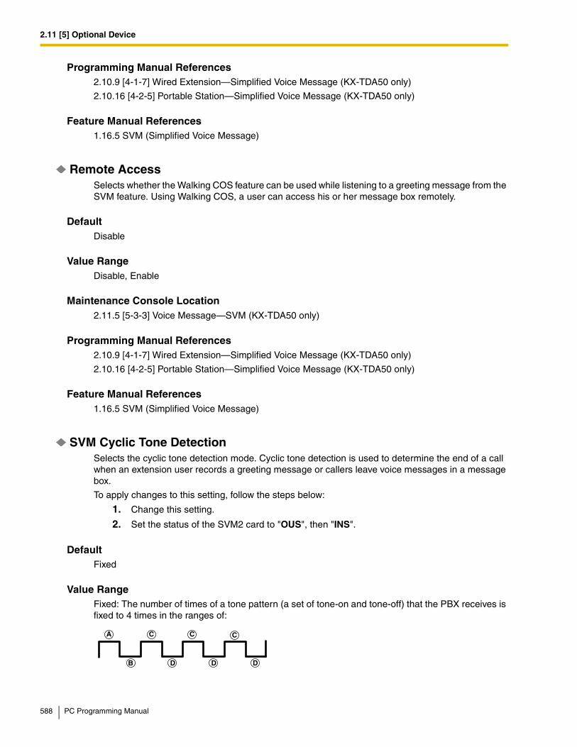
2.11 [5] Optional Device
Programming Manual References2.10.9 [4-1-7] Wired Extension—Simplified Voice Message (KX-TDA50 only)
2.10.16 [4-2-5] Portable Station—Simplified Voice Message (KX-TDA50 only)
Feature Manual References1.16.5 SVM (Simplified Voice Message)
Remote AccessSelects whether the Walking COS feature can be used while listening to a greeting message from the SVM feature. Using Walking COS, a user can access his or her message box remotely.
DefaultDisable
Value RangeDisable, Enable
Maintenance Console Location2.11.5 [5-3-3] Voice Message—SVM (KX-TDA50 only)
Programming Manual References2.10.9 [4-1-7] Wired Extension—Simplified Voice Message (KX-TDA50 only)
2.10.16 [4-2-5] Portable Station—Simplified Voice Message (KX-TDA50 only)
Feature Manual References1.16.5 SVM (Simplified Voice Message)
SVM Cyclic Tone DetectionSelects the cyclic tone detection mode. Cyclic tone detection is used to determine the end of a call when an extension user records a greeting message or callers leave voice messages in a message box.
To apply changes to this setting, follow the steps below:
1. Change this setting.
2. Set the status of the SVM2 card to "OUS", then "INS".
DefaultFixed
Value RangeFixed: The number of times of a tone pattern (a set of tone-on and tone-off) that the PBX receives is fixed to 4 times in the ranges of:
A
B
C
D
C C
D D
588 PC Programming Manual
2.11 [5] Optional Device
, = 100–1300 ms, = 90 ms, = 90 ms
Option: The tone pattern that the PBX receives is optional as specified in SVM Cyclic Tone Option on this screen.
Maintenance Console Location2.11.5 [5-3-3] Voice Message—SVM (KX-TDA50 only)
Programming Manual ReferencesNone
Feature Manual References1.16.5 SVM (Simplified Voice Message)
SVM Cyclic Tone Option—Tone On Maximum TimeSpecifies the maximum duration of the cyclic tone that will be recognized by the PBX. When the tone sent from the telephone company is shorter than the value set here, the PBX recognizes it as a tone-on.Note that this option can only be set when SVM Cyclic Tone Detection on this screen is set to "Option".
To apply changes to this setting, follow the steps below:
1. Change this setting.
2. Set the status of the SVM2 card to "OUS", then "INS".
Default600 ms
Value Range20 × n (n=6–200) ms
Maintenance Console Location2.11.5 [5-3-3] Voice Message—SVM (KX-TDA50 only)
Programming Manual References2.7.1 [1-1] Slot
Feature Manual References1.16.5 SVM (Simplified Voice Message)
SVM Cyclic Tone Option—Tone Off Maximum TimeSpecifies the maximum time that the PBX waits for a cyclic tone to be sent from the telephone company before recognizing it as a tone-off. When no tone is detected within the time set here, the PBX recognizes it as a tone-off.Note that this option can only be set when SVM Cyclic Tone Detection on this screen is set to "Option".
To apply changes to this setting, follow the steps below:
1. Change this setting.
A B C A D B
PC Programming Manual 589
2.11 [5] Optional Device
2. Set the status of the SVM2 card to "OUS", then "INS".
Default600 ms
Value Range20 × n (n=6–200) ms
Maintenance Console Location2.11.5 [5-3-3] Voice Message—SVM (KX-TDA50 only)
Programming Manual References2.7.1 [1-1] Slot
Feature Manual References1.16.5 SVM (Simplified Voice Message)
SVM Cyclic Tone Option—Repeating Times of On/Off for DetectionSpecifies the number of times the tone pattern (a set of tone-on and tone-off) must be received to establish reception of the cyclic tone. This determines the end of call.Note that this option can only be set when SVM Cyclic Tone Detection on this screen is set to "Option".
Default3
Value Range3–16
Maintenance Console Location2.11.5 [5-3-3] Voice Message—SVM (KX-TDA50 only)
Programming Manual ReferencesNone
Feature Manual References1.16.5 SVM (Simplified Voice Message)
2.11.6 [5-4] External Relay
Settings related to external relays can be programmed.
External Relay No.Indicates the number of the external relay (reference only).
590 PC Programming Manual

2.11 [5] Optional Device
DefaultCurrent external relay number.
Value RangeFor KX-TDA50:1–4
For KX-TDA100/KX-TDA200:1–16
KX-TDA600:1–64
Maintenance Console Location2.11.6 [5-4] External Relay
Programming Manual ReferencesNone
Feature Manual References1.5.8 External Relay
Physical Location—Shelf (KX-TDA600 only)Indicates the shelf position (reference only).
DefaultCurrent shelf number
Value RangeShelf number
Maintenance Console Location2.11.6 [5-4] External Relay
Programming Manual ReferencesNone
Feature Manual References1.5.8 External Relay
Physical Location—SlotIndicates the slot position (reference only).
DefaultCurrent slot and sub-slot number.
PC Programming Manual 591
2.11 [5] Optional Device
Value RangeFor KX-TDA50:Slot number
For KX-TDA100/KX-TDA200/KX-TDA600:Slot and sub-slot number
Maintenance Console Location2.11.6 [5-4] External Relay
Programming Manual ReferencesNone
Feature Manual References1.5.8 External Relay
Physical Location—PortIndicates the port number (reference only).
DefaultCurrent port number.
Value RangePort number
Maintenance Console Location2.11.6 [5-4] External Relay
Programming Manual ReferencesNone
Feature Manual References1.5.8 External Relay
NameSpecifies the relay name.
DefaultNot stored.
Value RangeMax. 20 characters
Maintenance Console Location2.11.6 [5-4] External Relay
592 PC Programming Manual
2.11 [5] Optional Device
Programming Manual ReferencesNone
Feature Manual References1.5.8 External Relay
Relay Activate TimeSpecifies the length of time that the relay stays on when activated.
Default5 s
Value Range1–7 s
Maintenance Console Location2.11.6 [5-4] External Relay
Programming Manual ReferencesNone
Feature Manual References1.5.8 External Relay
COS NumberSpecifies the Class of Service (COS) number. COS programming determines the extensions that are able to activate relays.
Default1
Value Range1–64
Maintenance Console Location2.11.6 [5-4] External Relay
Programming Manual References2.8.11 [2-7-1] Class of Service—COS Settings—Optional Device & Other Extension—External Relay Access
Feature Manual References1.3.19 COS (Class of Service)
1.5.8 External Relay
1.9.14 Internal Call Block
PC Programming Manual 593

2.11 [5] Optional Device
2.11.7 [5-5] External Sensor
Settings related to external sensors can be programmed.To assign destinations for sensor calls easily, click Extension Number of Destination Setting (see 2.1.6 Extension Number Setting).
External Sensor No.Indicates the number of the external sensor (reference only).
DefaultCurrent external sensor number.
Value RangeFor KX-TDA50:1–4
For KX-TDA100/KX-TDA200:1–16
KX-TDA600:1–64
Maintenance Console Location2.11.7 [5-5] External Sensor
Programming Manual ReferencesNone
Feature Manual References1.5.9 External Sensor
Physical Location—Shelf (KX-TDA600 only)Indicates the shelf position (reference only).
DefaultCurrent shelf number
Value RangeShelf number
Maintenance Console Location2.11.7 [5-5] External Sensor
Programming Manual ReferencesNone
594 PC Programming Manual

2.11 [5] Optional Device
Feature Manual References1.5.9 External Sensor
Physical Location—SlotIndicates the slot position (reference only).
DefaultCurrent slot and sub-slot number.
Value RangeFor KX-TDA50:Slot number
For KX-TDA100/KX-TDA200/KX-TDA600:Slot and sub-slot number
Maintenance Console Location2.11.7 [5-5] External Sensor
Programming Manual ReferencesNone
Feature Manual References1.5.9 External Sensor
Physical Location—PortIndicates the port number (reference only).
DefaultCurrent port number.
Value RangePort number
Maintenance Console Location2.11.7 [5-5] External Sensor
Programming Manual ReferencesNone
Feature Manual References1.5.9 External Sensor
NameSpecifies the sensor name.
PC Programming Manual 595

2.11 [5] Optional Device
DefaultSensor
Value RangeMax. 20 characters
Maintenance Console Location2.11.7 [5-5] External Sensor
Programming Manual ReferencesNone
Feature Manual References1.5.9 External Sensor
Destination—Day, Lunch, Break, NightSpecifies the destination number of sensor calls for each port in each time mode.
DefaultNot stored.
Value RangeMax. 32 digits (consisting of 0–9, *, #, [ ] [Secret], and P [Pause])
Maintenance Console Location2.11.7 [5-5] External Sensor
Programming Manual ReferencesNone
Feature Manual References1.5.9 External Sensor
Tenant No.Specifies the tenant to which the sensor belongs, to determine the Time Table for the sensor. (The tenant number corresponds to the Time Table number.)
Default1
Value Range1–8
Maintenance Console Location2.11.7 [5-5] External Sensor
596 PC Programming Manual

2.11 [5] Optional Device
Programming Manual References2.8.5 [2-4] Week Table
Feature Manual References1.5.9 External Sensor
1.17.3 Tenant Service
PC Programming Manual 597

2.12 [6] Feature
2.12 [6] Feature
2.12.1 [6-1] System Speed Dial
The System Speed Dialing Table is used to store frequently dialed numbers as well as callers who should be automatically routed to certain extensions when they call (Calling Line Identification [CLI] distribution). The System Speed Dialing Table is available for all extension users when making or receiving a call.A maximum of 1000 System Speed Dialing numbers (e.g., telephone numbers, feature numbers) can be programmed with other related parameters. 100 numbers are displayed at a time. To display other sets of numbers, click the applicable tab.
MemorySelects the System Speed Dialing Table to be programmed. Whether a tenant uses the basic System Speed Dialing Table or the additional table (with MEC [KX-TDA50/KX-TDA100/KX-TDA200] or EMEC [KX-TDA600] card) depends on the setting of System Speed Dial in 2.12.6 [6-6] Tenant.
DefaultBasic Memory
Value RangeFor KX-TDA50:Basic Memory: the standard tableExpanded Memory: additional table (only available when an MEC card is installed to the PBX)
For KX-TDA100/KX-TDA200/KX-TDA600:Basic Memory: the standard tableExpanded Memory for Tenant 1–8: additional tables (only available when an MEC/EMEC card is installed to the PBX)
Maintenance Console Location2.12.1 [6-1] System Speed Dial
Programming Manual References2.12.6 [6-6] Tenant—System Speed Dial
Feature Manual References1.16.4 Speed Dialing, System
1.17.3 Tenant Service
NameSpecifies a name for the System Speed Dialing number.
DefaultNot stored.
598 PC Programming Manual

2.12 [6] Feature
Value RangeMax. 20 characters
Maintenance Console Location2.12.1 [6-1] System Speed Dial
Programming Manual ReferencesNone
Feature Manual References1.16.4 Speed Dialing, System
CO Line Access Number + Telephone NumberSpecifies the telephone number (including the CO Line Access number) or feature number assigned to the System Speed Dialing number.
DefaultNot stored.
Value RangeMax. 32 digits (consisting of 0–9, *, #, T [Transfer], [ ] [Secret], P [Pause], and F [Flash])
Maintenance Console Location2.12.1 [6-1] System Speed Dial
Programming Manual ReferencesNone
Feature Manual References1.16.4 Speed Dialing, System
CLI DestinationSpecifies the CLI destination (extension) to which incoming calls from the programmed telephone number are routed. If a Caller ID Modification Table is being used, the modified number must match the telephone number above (CO Line Access Number + Telephone Number) in order for the call to be routed correctly.
DefaultNot stored.
Value RangeMax. 5 digits (consisting of 0–9)
Maintenance Console Location2.12.1 [6-1] System Speed Dial
PC Programming Manual 599

2.12 [6] Feature
Programming Manual References2.16.2 [10-2] DIL Table & Port Settings—CLI for DIL—CLI Ring for DIL—Day, Lunch, Break, Night
2.16.3 [10-3] DID Table (KX-TDA100/KX-TDA200/KX-TDA600 only)—CLI Ring for DID—Day, Lunch, Break, Night
Feature Manual References1.3.1 Caller ID
1.3.12 CLI (Calling Line Identification) Distribution
2.12.2 [6-2] Caller ID Modification
The telephone numbers of incoming callers can be modified automatically by a Caller ID Modification Table, and then recorded for calling back.
Caller ID ModificationThe PBX looks for incoming telephone numbers that begin with an area code programmed in the Caller ID Modification Table assigned to that trunk group. If it finds such a code, it removes digits and adds a number to the telephone number. If this modified telephone number is stored as a System Speed Dialing number, the caller's name can be shown on a PT display and the call can be routed to a certain extension (CLI destination). A maximum of 4 Caller ID Modification Tables, each containing 10 local/international call data and 1 long distance code, can be programmed. Each trunk group can select a table for use. Select the desired table from the Modification Table list.If the telephone number does not contain an area code programmed here, it is modified based on the Long Distance Code settings.
Area Code (for Local / International Call Data 1–10)Specifies the leading number (area code) to look for in the incoming caller's number.
DefaultNot stored.
Value RangeMax. 6 digits (consisting of 0–9, *, and #)
Maintenance Console Location2.12.2 [6-2] Caller ID Modification
Programming Manual References2.9.1 [3-1-1] Trunk Group—TRG Settings—Caller-ID Modification Table
2.12.1 [6-1] System Speed Dial
Feature Manual References1.3.1 Caller ID
Removed Number of DigitsSpecifies the number of digits to be removed from the beginning of the incoming caller's number.
600 PC Programming Manual
2.12 [6] Feature
DefaultLocal / International Call Data 1–10: 3Long Distance Code: 0
Value Range0–9
Maintenance Console Location2.12.2 [6-2] Caller ID Modification
Programming Manual References2.9.1 [3-1-1] Trunk Group—TRG Settings—Caller-ID Modification Table
2.12.1 [6-1] System Speed Dial
Feature Manual References1.3.1 Caller ID
Added NumberSpecifies the number to be added to the incoming caller's number in the place of the removed digits.
DefaultLocal / International Call Data 1–10: Not stored. Long Distance Code: 1 (fixed)
Value RangeMax. 4 digits (consisting of 0–9, *, and #)
Maintenance Console Location2.12.2 [6-2] Caller ID Modification
Programming Manual References2.9.1 [3-1-1] Trunk Group—TRG Settings—Caller-ID Modification Table
2.12.1 [6-1] System Speed Dial
Feature Manual References1.3.1 Caller ID
ISDN CLIP Modification (KX-TDA100/KX-TDA200/KX-TDA600 only)When incoming caller information is sent through an ISDN line and the type of the network numbering plan is International, National, or Subscriber, the caller's number can be modified as programmed in the Modification Tables assigned to the trunk group. The modified number will then be recorded, and it is used for sending to the network as a CLIP number.A maximum of 4 ISDN CLIP Modification Tables can be programmed. Select the desired table from the Modification Table list.
PC Programming Manual 601

2.12 [6] Feature
Removed Number of Digits (KX-TDA100/KX-TDA200/KX-TDA600 only)Specifies the number of leading digits to be removed from the incoming caller's number for each type of network numbering plan.
DefaultInternational: 0National: 0Subscriber: 0
Value Range0–9
Maintenance Console Location2.12.2 [6-2] Caller ID Modification
Programming Manual References2.7.14 [1-1] Slot—PRI Port (KX-TDA100/KX-TDA200/KX-TDA600 only)—Calling Party number—Type of Number—Public, Private
2.7.14 [1-1] Slot—PRI Port (KX-TDA100/KX-TDA200/KX-TDA600 only)—Called Party number—Type of Number—Public, Private
Feature Manual References1.3.1 Caller ID
Added Number (KX-TDA100/KX-TDA200/KX-TDA600 only)Specifies the number to be added to the incoming caller's number in the place of the removed digits for each type of network numbering plan.
DefaultInternational: 011National: 1Subscriber: Not stored.
Value RangeMax. 4 digits (consisting of 0–9, *, and #)
Maintenance Console Location2.12.2 [6-2] Caller ID Modification
Programming Manual References2.7.14 [1-1] Slot—PRI Port (KX-TDA100/KX-TDA200/KX-TDA600 only)—Calling Party number—Type of Number—Public, Private
2.7.14 [1-1] Slot—PRI Port (KX-TDA100/KX-TDA200/KX-TDA600 only)—Called Party number—Type of Number—Public, Private
Feature Manual References1.3.1 Caller ID
602 PC Programming Manual

2.12 [6] Feature
2.12.3 [6-3] Verification Code
A verification code is used to override the Toll Restriction (TRS) of the extension in use to make a certain CO line call, or to identify the call for accounting and billing purposes.A maximum of 1000 verification codes can be programmed with other related parameters. 100 codes are displayed at a time. To display other sets of codes, click the applicable tab.
Verification CodeSpecifies the verification code.
DefaultNot stored.
Value RangeMax. 4 digits (consisting of 0–9, *, and #)
Maintenance Console Location2.12.3 [6-3] Verification Code
Programming Manual ReferencesNone
Feature Manual References1.19.1 Verification Code Entry
User NameSpecifies the user name assigned to the verification code.
DefaultNot stored.
Value RangeMax. 20 characters
Maintenance Console Location2.12.3 [6-3] Verification Code
Programming Manual ReferencesNone
Feature Manual References1.19.1 Verification Code Entry
Verification Code PINSpecifies the PIN to be entered when making a CO line call with the verification code.
PC Programming Manual 603

2.12 [6] Feature
DefaultNot stored.
Value RangeMax. 10 digits (consisting of 0–9)
Maintenance Console Location2.12.3 [6-3] Verification Code
Programming Manual ReferencesNone
Feature Manual References1.19.1 Verification Code Entry
WARNING
There is a risk that fraudulent telephone calls will be made if a third party discovers a personal identification number (PIN) (verification code PIN or extension PIN) of the PBX.The cost of such calls will be billed to the owner/renter of the PBX.To protect the PBX from this kind of fraudulent use, we strongly recommend:a) Keeping PINs secret.
b) Selecting complex, random PINs that cannot be easily guessed.
c) Changing PINs frequently.
COS NumberSpecifies the COS that applies when making a CO line call with the verification code.
Default1
Value Range1–64
Maintenance Console Location2.12.3 [6-3] Verification Code
Programming Manual References2.8.11 [2-7-1] Class of Service—COS Settings
Feature Manual References1.3.19 COS (Class of Service)
1.19.1 Verification Code Entry
604 PC Programming Manual

2.12 [6] Feature
Itemized Billing Code for ARSSpecifies the itemized billing code used by the ARS feature for identifying calls made with a verification code for accounting and billing purposes.
DefaultNot stored.
Value RangeMax. 10 digits (consisting of 0–9, *, and #)
Maintenance Console Location2.12.3 [6-3] Verification Code
Programming Manual References2.14.6 [8-5] Carrier
Feature Manual References1.1.3 ARS (Automatic Route Selection)
2.12.4 [6-4] Second Dial Tone
A programmed Pause time can be inserted automatically between the Second Dial Tone Waiting code and the following digits. When a programmed Second Dial Tone Waiting code is dialed after seizing a CO line, a preprogrammed number of pauses are inserted after the code.A maximum of 100 Second Dial Tone Waiting codes can be programmed. 20 codes are displayed at a time. To display other sets of codes, click the applicable tab.
Second Dial Tone Waiting CodeSpecifies the Second Dial Tone Waiting code.
DefaultNot stored.
Value RangeMax. 4 digits (consisting of 0–9, *, and #)
Maintenance Console Location2.12.4 [6-4] Second Dial Tone
Programming Manual ReferencesNone
Feature Manual References1.13.4 Pause Insertion
PC Programming Manual 605
2.12 [6] Feature
Pause Repeating CounterSpecifies the number of pauses to be inserted when waiting for the second dial tone.
Default1
Value Range0–20
Maintenance Console Location2.12.4 [6-4] Second Dial Tone
Programming Manual ReferencesNone
Feature Manual References1.13.4 Pause Insertion
2.12.5 [6-5] Absent Message
When a display PT user calls an extension, a message is shown on the caller's telephone display describing the reason for absence. A maximum of 8 Absent Messages can be programmed, and any extension user can select one of them.
Absent MessageSpecifies the message for display.
Default1: Will Return Soon
2: Gone Home
3: At Ext %%%% (Extension Number)
4: Back at %%:%% (Hour:Minute)
5: Out until %%/%% (Month/Day)
6: In a Meeting
7 and 8: Not stored.
Value RangeMax. 16 characters
Maintenance Console Location2.12.5 [6-5] Absent Message
Programming Manual ReferencesNone
606 PC Programming Manual

2.12 [6] Feature
Feature Manual References1.1.1 Absent Message
2.12.6 [6-6] Tenant
A maximum of 8 tenants can share the PBX. Each tenant is composed of specified extension user groups. The PBX offers each tenant its own Time Table and system resources.To assign extensions as operators easily, click Extension Number Setting (see 2.1.6 Extension Number Setting).
Music On HoldSpecifies the audio source to be used for Music on Hold.
DefaultSame as System Setting
Value RangeFor KX-TDA50:Same as System Setting, BGM, Tone
For KX-TDA100/KX-TDA200/KX-TDA600:Same as System Setting, BGM 1, BGM 2, Tone
Maintenance Console Location2.12.6 [6-6] Tenant
Programming Manual References2.8.3 [2-2] Operator & BGM
Feature Manual References1.11.4 Music on Hold
1.17.3 Tenant Service
Operator (Extension Number)Specifies the extension number or the floating extension number of an incoming call distribution group to be designated as the tenant operator. When this parameter is left unspecified, the PBX operator serves as the tenant operator.
DefaultNot stored.
Value RangeMax. 5 digits (consisting of 0–9)
Maintenance Console Location2.12.6 [6-6] Tenant
PC Programming Manual 607

2.12 [6] Feature
Programming Manual References2.8.3 [2-2] Operator & BGM
Feature Manual References1.12.5 Operator Features
1.17.3 Tenant Service
ARS ModeSpecifies the ARS mode used when making a CO line call.
DefaultSame as System Setting
Value RangeOff: ARS is disabled.
On for Local Access Operation: ARS operates when an extension user makes a call using any Idle Line Access method.
On for Any CO Access Operation: ARS operates when an extension user makes a call using any CO Line Access method.
Same as System Setting: The setting specified in ARS Mode in 2.14.1 [8-1] System Settings is applied.
Maintenance Console Location2.12.6 [6-6] Tenant
Programming Manual References2.14.1 [8-1] System Settings
Feature Manual References1.1.3 ARS (Automatic Route Selection)
1.17.3 Tenant Service
System Speed DialSpecifies which system speed dialing table is used by the tenant. This setting is only available when an MEC (KX-TDA50/KX-TDA100/KX-TDA200) or EMEC (KX-TDA600) card is installed.
DefaultFor KX-TDA50:Basic Memory
For KX-TDA100/KX-TDA200/KX-TDA600:Same as System Setting
Value RangeFor KX-TDA50:Basic Memory: PBX basic system speed dialing numbers are used.
608 PC Programming Manual
2.12 [6] Feature
Expanded Memory: Expansion system speed dialing numbers are used.
For KX-TDA100/KX-TDA200/KX-TDA600:Same as System Setting: PBX common system speed dialing numbers are used.Tenant Exclusive: Individual tenant system speed dialing numbers are used.
Maintenance Console Location2.12.6 [6-6] Tenant
Programming Manual References2.12.1 [6-1] System Speed Dial
Feature Manual References1.16.4 Speed Dialing, System
1.17.3 Tenant Service
2.12.7 [6-7] Dialing Plan
The PBX sends all of the dialed digits at once after an extension user completes dialing. The PBX can recognize the end of dialing when the dialed telephone number starts with the programmed leading number and contains the programmed total number of digits.When the PBX recognizes the end of dialing to an analog CO line, the PBX cancels the muting of the caller's voice sent to the analog CO line immediately. If the PBX cannot recognize the end of dialing, the PBX mutes the caller's voice sent to an analog CO line from the time at which the last digit is dialed until the analog CO line inter-digit timer expires.4 tables can be programmed, each with a maximum of 50 leading numbers. Select the table to program from the Dialing Plan Table list.
To assign a set of leading numbers automatically, click Auto Assign.
Leading NumberSpecifies the leading number to be regarded as the beginning of dialing.
DefaultNo. 1 in Dialing Plan Table 1: N11No. 2 in Dialing Plan Table 1: NXX NXX XXXXNo. 3 in Dialing Plan Table 1: 1NXX NXX XXXXOthers: Not stored.
Value RangeMax. 32 digits (consisting of 0–9, *, #, N [2,3,4,5,6,7,8,9], P [0, 1], and X [0-9, *, and #])
Maintenance Console Location2.12.7 [6-7] Dialing Plan
Programming Manual References2.8.4 [2-3] Timers & Counters—Dial / IRNA / Recall / Tone—Dial—Analog CO First Digit
2.8.4 [2-3] Timers & Counters—Dial / IRNA / Recall / Tone—Dial—Analog CO Inter-digit
PC Programming Manual 609

2.12 [6] Feature
2.9.1 [3-1-1] Trunk Group—TRG Settings—Main—Dialing Plan Table (MPR Software File Version 4.0000 or later)
Feature Manual References1.9.16 ISDN (INTEGRATED SERVICES DIGITAL NETWORK) FEATURES
Removed Number of Digits (MPR Software File Version 4.0000 or later)Specifies the number of leading digits of the dialed number to be removed.
Default0
Value Range0–15
Maintenance Console Location2.12.7 [6-7] Dialing Plan
Programming Manual ReferencesNone
Feature Manual References1.9.16 ISDN (INTEGRATED SERVICES DIGITAL NETWORK) FEATURES
Added Number (MPR Software File Version 4.0000 or later)Specifies the number to be added to the dialed number in place of the removed digits.
DefaultNot stored.
Value RangeMax. 32 digits (consisting of 0–9, *, #, and P [Pause])
Maintenance Console Location2.12.7 [6-7] Dialing Plan
Programming Manual ReferencesNone
Feature Manual References1.9.16 ISDN (INTEGRATED SERVICES DIGITAL NETWORK) FEATURES
2.12.8 [6-7] Dialing Plan—Auto Assign
It is possible to assign a set of leading numbers automatically.
610 PC Programming Manual

2.12 [6] Feature
Select Auto Assigning TableSelects the set of preset leading number values to assign to the active dialing plan table. When Type D is selected, you will be prompted to enter a 3-digit area code, and 7 "X"s, in cells 1 through 47 of the dialing plan table.
DefaultType A
Value RangeType A: 1:N11, 2:NXX XXXX, 3:1NXX NXX XXXX, 4-50: Not storedType B: 1:N11, 2:NNX XXXX, 3:1NPX NXX XXXX, 4-50: Not storedType C: 1:N11, 2:NXX XXXX, 3:1NNX XXXX, 4:1NPX NXX XXXX, 5-50: Not storedType D: 1-47: Not stored, 48:N11, 49:NXX XXXX, 50:1NXX NXX XXXXType E: 1:N11, 2:NXX NXX XXXX, 3:1NXX NXX XXXX, 4-50: Not stored
Maintenance Console Location2.12.8 [6-7] Dialing Plan—Auto Assign
Programming Manual References2.12.7 [6-7] Dialing Plan
Feature Manual ReferencesNone
2.12.9 [6-8] Hotel
Various settings related to the hospitality features of the PBX can be set.
Main
Hotel Operator—Extension 1–4Specifies the numbers of the extensions designated as hotel operators.
DefaultFor KX-TDA50/KX-TDA100/KX-TDA200:Extension 1: 101
For KX-TDA600:Extension 1: 1001
Value RangeMax. 5 digits (consisting of 0–9)
Maintenance Console Location2.12.9 [6-8] Hotel
PC Programming Manual 611

2.12 [6] Feature
Programming Manual ReferencesNone
Feature Manual References1.8.4 HOSPITALITY FEATURES
1.15.3 Room Status Control
SMDR for External Hotel Application 1—Room Status ControlSelects whether check-in and check-out data is output on SMDR.
DefaultNo Print
Value RangeNo Print, Print
Maintenance Console Location2.12.9 [6-8] Hotel
Programming Manual References2.17.1 [11-1] Main
Feature Manual References1.15.3 Room Status Control
1.16.1 SMDR (Station Message Detail Recording)
SMDR for External Hotel Application 1—Timed Reminder (Wake-up Call)Selects whether Timed Reminder data is output on SMDR.
DefaultNo Print
Value RangeNo Print, Print
Maintenance Console Location2.12.9 [6-8] Hotel
Programming Manual References2.17.1 [11-1] Main
Feature Manual References1.16.1 SMDR (Station Message Detail Recording)
1.17.4 Timed Reminder
612 PC Programming Manual

2.12 [6] Feature
SMDR for External Hotel Application 2—Printing Message 1–8Specifies the text of the message output on SMDR when this Printing Message is selected from an extension.The "%" character can be used in a message, and requires a number to be entered in its place when the message is selected from an extension. This character can be used a maximum of seven times in a Printing Message.
DefaultNot stored.
Value RangeMax. 16 characters
Maintenance Console Location2.12.9 [6-8] Hotel
Programming Manual References2.17.1 [11-1] Main
Feature Manual References1.13.11 Printing Message
1.16.1 SMDR (Station Message Detail Recording)
PC Programming Manual 613
2.13 [7] TRS
2.13 [7] TRS
2.13.1 [7-1] Denied Code
Toll Restriction (TRS) prohibits an extension from making certain CO line calls. Each time mode of every COS is assigned one of the seven TRS levels. TRS level 7 provides the maximum restriction (all CO line calls are prohibited) and level 1 provides the minimum (all CO line calls are allowed). TRS levels 2–6 are used to restrict calls according to the codes programmed in the Denied Code Tables here and Exception Code Tables in 2.13.2 [7-2] Exception Code. If the leading digits of the dialed number are not found in the applicable Denied Code Tables, the call is made.A maximum of 100 denied codes can be programmed for each level. 20 codes are displayed at a time. To display other sets of codes, click the applicable tab.
Denied Code Tables—Level 2–Level 6Specifies the leading digits of toll restricted numbers for each level.
DefaultNot stored.
Value RangeMax. 16 digits (consisting of 0–9, *, #, and X)
Maintenance Console Location2.13.1 [7-1] Denied Code
Programming Manual References2.8.11 [2-7-1] Class of Service—COS Settings—TRS—TRS Level—Day, Lunch, Break, Night
2.13.2 [7-2] Exception Code
Feature Manual References1.17.6 TRS (Toll Restriction)
2.13.2 [7-2] Exception Code
Toll Restriction (TRS) prohibits an extension from making certain CO line calls. Each time mode of every COS is assigned one of the seven TRS levels. TRS level 7 provides the maximum restriction (all CO line calls are prohibited) and level 1 provides the minimum (all CO line calls are allowed). TRS levels 2–6 are used to restrict calls according to the codes programmed in the Denied Code Tables in 2.13.1 [7-1] Denied Code and Exception Code Tables here. A call denied by the applicable Denied Code Tables is checked against the applicable Exception Code Tables, and if a match is found, the call is made.A maximum of 100 exception codes can be programmed for each level. 20 codes are displayed at a time. To display other sets of codes, click the applicable tab.
614 PC Programming Manual

2.13 [7] TRS
Exception Code Tables—Level 2–Level 6Specifies the leading digits of the numbers to be exempted from Toll Restriction for each level.
DefaultNot stored.
Value RangeMax. 16 digits (consisting of 0–9, *, #, and X)
Maintenance Console Location2.13.2 [7-2] Exception Code
Programming Manual References2.8.11 [2-7-1] Class of Service—COS Settings—TRS—TRS Level—Day, Lunch, Break, Night
2.13.1 [7-1] Denied Code
Feature Manual References1.17.6 TRS (Toll Restriction)
2.13.3 [7-3] Special Carrier Code
If the PBX has access to multiple telephone companies, a Special Carrier Access Code is required each time a CO line call is made. By programming these Special Carrier Access Codes here, Toll Restriction (TRS) can restrict or allow calls to be made by ignoring the codes and looking at the telephone number only. If a Special Carrier Access Code is found in the dialed number, TRS will look only at the following digits.A maximum of 20 (with the KX-TDA50/KX-TDA100/KX-TDA200) or 100 (with the KX-TDA600) Special Carrier Access Codes can be programmed. With the KX-TDA600, 20 codes are displayed at a time. To show other sets of codes, click the applicable tab.
Special Carrier Access CodeSpecifies a Special Carrier Access Code. Special Carrier Access Codes and Host PBX Access codes should be unique.
DefaultNot stored.
Value RangeMax. 16 digits (consisting of 0–9, *, and #)
Maintenance Console Location2.13.3 [7-3] Special Carrier Code
Programming Manual ReferencesNone
PC Programming Manual 615

2.13 [7] TRS
Feature Manual References1.16.2 Special Carrier Access Code
1.17.6 TRS (Toll Restriction)
2.13.4 [7-4] Emergency Dial
Any extension user can dial the programmed emergency numbers at any time after seizing a CO line. The restrictions imposed on the extension, such as Toll Restriction (TRS), Account Code—Forced mode, and Extension Dial Lock are disregarded.A maximum of 10 emergency numbers can be programmed.
Emergency NumberSpecifies the numbers used for making emergency calls. It is not necessary to start the emergency number with a CO Line Access number.
Default1: 911, 2–10: Not stored.
Value RangeMax. 32 digits (consisting of 0–9, *, #, T [Transfer], P [Pause], and F [Flash])
Maintenance Console Location2.13.4 [7-4] Emergency Dial
Programming Manual ReferencesNone
Feature Manual References1.5.2 Emergency Call
2.13.5 [7-5] Miscellaneous
Toll Restriction (TRS) prohibits an extension from making certain CO line calls. The following optional settings can be programmed to activate a TRS check, override TRS, or switch between TRS methods.
TRS Override by System Speed DialingEnables an outgoing CO line call to override TRS when the call is made using System Speed Dialing.
DefaultEnable
Value RangeDisable, Enable
616 PC Programming Manual
2.13 [7] TRS
Maintenance Console Location2.13.5 [7-5] Miscellaneous
Programming Manual References2.12.1 [6-1] System Speed Dial
Feature Manual References1.17.6 TRS (Toll Restriction)
TRS Check for dial "* #"Enables a TRS check for the user-dialed " " and "#". This is useful in preventing unauthorized calls which could possibly be made through certain telephone company exchanges.
DefaultNo Check
Value RangeNo Check, Check
Maintenance Console Location2.13.5 [7-5] Miscellaneous
Programming Manual ReferencesNone
Feature Manual References1.17.6 TRS (Toll Restriction)
Mode when Dial Time-out before TRS CheckSelects whether a CO line is disconnected if the TRS check has not been completed when the CO line Inter-digit timer expires.
DefaultDisconnect
Value RangeDisconnect: The CO line is disconnected as soon as the timer expires.
Keep: The TRS check is performed when the timer expires.
Maintenance Console Location2.13.5 [7-5] Miscellaneous
Programming Manual References2.8.4 [2-3] Timers & Counters
PC Programming Manual 617

2.13 [7] TRS
Feature Manual References1.17.6 TRS (Toll Restriction)
Dial Digits Limitation After Answering—Dial DigitsSpecifies a limit to be placed on the number of digits which can be dialed after an extension user receives a CO line call. If the number of dialed digits exceeds the programmed limit, the line will be disconnected.
DefaultNone
Value RangeNone, 1–7
Maintenance Console Location2.13.5 [7-5] Miscellaneous
Programming Manual ReferencesNone
Feature Manual References1.3.15 CO Line Call Limitation
1.17.6 TRS (Toll Restriction)
TRS Check after EFAEnables TRS to check the digits dialed after External Feature Access (EFA) during a CO line call.
DefaultEnable
Value RangeDisable, Enable
Maintenance Console Location2.13.5 [7-5] Miscellaneous
Programming Manual ReferencesNone
Feature Manual References1.5.1 EFA (External Feature Access)
1.17.6 TRS (Toll Restriction)
618 PC Programming Manual

2.13 [7] TRS
TRS Table Mode for Level N (N=2_6) (MPR Software File Version 3.2000 or later)
Selects the method of TRS to be used for restricting calls. The level of TRS is determined by the telephone codes set in the Denied Code Tables and Exception Code Tables.
DefaultDeny Table 2_N + Except Table N_6
Value RangeDeny Table 2_N + Except Table N_6: The Denied Code Tables for the higher levels are applied to all levels below it, and the Exception Code Tables for the lower levels are applied to all levels above it.Deny Table N + Except Table N: Each level has its own separate set of denied codes and exception codes, which are only applied to that level.
Maintenance Console Location2.13.5 [7-5] Miscellaneous
Programming Manual ReferencesNone
Feature Manual References1.17.6 TRS (Toll Restriction)
PC Programming Manual 619
2.14 [8] ARS
2.14 [8] ARS
2.14.1 [8-1] System Settings
Automatic Route Selection (ARS) automatically selects the appropriate carrier at the time a CO line call is made, according to the programmed settings. The user-dialed number will be checked and modified in order to connect it to the appropriate carrier.
ARS ModeSelects the condition to determine when to operate ARS.
DefaultOff
Value RangeOff: ARS is disabled.
On for Local Access Operation: ARS operates when an extension user makes a call using Idle Line Access method.
On for Any CO Access Operation: ARS operates when an extension user makes a call using Idle Line Access, CO Line Access, or S-CO Line Access method.
Maintenance Console Location2.14.1 [8-1] System Settings
Programming Manual ReferencesNone
Feature Manual References1.1.3 ARS (Automatic Route Selection)
1.3.14 CO Line Access
Mode When Any Carrier is not programmed for the DialSelects what happens when the dialed number is not found in Leading Number in 2.14.2 [8-2] Leading Number.
DefaultLocal Access
Value RangeDisconnect: the line will be disconnected.
Local Access: the dialed number will be handled by Idle Line Access method.
Maintenance Console Location2.14.1 [8-1] System Settings
620 PC Programming Manual
2.14 [8] ARS
Programming Manual ReferencesNone
Feature Manual References1.1.3 ARS (Automatic Route Selection)
2.14.2 [8-2] Leading Number
Specifies the area codes and/or telephone numbers as leading numbers that will be routed by the ARS feature. A maximum of 1000 different leading numbers can be programmed, and each leading number can select a Routing Plan Table number, which determines the ARS procedure.The additional (remaining) number of digits can also be specified for each leading number. The additional (remaining) number of digits must be specified only when "#", for example, is needed after the dialed number. The "#" will be added after the programmed number of digits of the user-dialed number (excluding the leading number).100 leading numbers are displayed at a time. To display other sets of leading numbers, click the applicable tab.
Leading NumberSpecifies the leading number.
DefaultNot stored.
Value RangeMax. 16 digits (consisting of 0–9, *, #, and X)
Maintenance Console Location2.14.2 [8-2] Leading Number
Programming Manual ReferencesNone
Feature Manual References1.1.3 ARS (Automatic Route Selection)
Additional Number of DigitsSpecifies the additional (remaining) number of digits following each leading number.
Default0
Value Range0–15
PC Programming Manual 621
2.14 [8] ARS
Maintenance Console Location2.14.2 [8-2] Leading Number
Programming Manual ReferencesNone
Feature Manual References1.1.3 ARS (Automatic Route Selection)
Routing Plan NumberSpecifies the Routing Plan Table number used for each leading number.
Default1
Value RangeFor KX-TDA50/KX-TDA100/KX-TDA200:1–16
For KX-TDA600:1–48
Maintenance Console Location2.14.2 [8-2] Leading Number
Programming Manual ReferencesNone
Feature Manual References1.1.3 ARS (Automatic Route Selection)
2.14.3 [8-3] Routing Plan Time
The start and end times of a maximum of 4 different time blocks are shown for each day of the week. There are 16 (with the KX-TDA50/KX-TDA100/KX-TDA200) or 48 (with the KX-TDA600) Routing Plan Tables, and each Routing Plan Table can have its own time blocks. Select the desired Routing Plan Table number from the Routing Plan list.
• To adjust the currently displayed Routing Plan, click and drag the divisions between two time periods.
• To program the time blocks of the currently displayed Routing Plan, including adding or deleting time blocks, click Time Setting.
2.14.4 [8-3] Routing Plan Time—Time Setting
The start times of a maximum of 4 different time blocks can be programmed for each day of the week, for the selected Routing Plan. Each time block automatically ends when the subsequent block begins.
622 PC Programming Manual
2.14 [8] ARS
Time-A–D—SettingEnables the setting of the start time for each time block.
DefaultTime-A–Time-C: Enable
Time-D: Disable
Value RangeDisable, Enable
Maintenance Console Location2.14.4 [8-3] Routing Plan Time—Time Setting
Programming Manual ReferencesNone
Feature Manual References1.1.3 ARS (Automatic Route Selection)
Time-A–D—Hour, MinuteSpecifies the start time for each time block.
DefaultTime-A: 8:00, Time-B: 17:00, Time-C: 21:00, Time-D: Not applicable.
Value Range00:00–23:59
Maintenance Console Location2.14.4 [8-3] Routing Plan Time—Time Setting
Programming Manual ReferencesNone
Feature Manual References1.1.3 ARS (Automatic Route Selection)
2.14.5 [8-4] Routing Plan Priority
The carrier priority (1 through 6) in a Routing Plan Table can be programmed for each time zone of each day of the week. Select the desired Routing Plan Table number from the Routing Plan list. Select the desired day of the week by clicking the applicable tab.
Time-A–Time-DSpecifies the carrier to be given priority for each time zone.
PC Programming Manual 623

2.14 [8] ARS
DefaultPriority 1: 1Priority 2–6: None
Value RangeFor KX-TDA50/KX-TDA100/KX-TDA200:None, 1–10
For KX-TDA600:None, 1–48
Maintenance Console Location2.14.5 [8-4] Routing Plan Priority
Programming Manual ReferencesNone
Feature Manual References1.1.3 ARS (Automatic Route Selection)
2.14.6 [8-5] Carrier
CarrierIt is possible to specify how user-dialed numbers are modified for connecting to the appropriate carrier. A maximum of 10 (with the KX-TDA50/KX-TDA100/KX-TDA200) or 48 (with the KX-TDA600) different carriers can be programmed to be used with the ARS feature.
Carrier NameSpecifies the carrier name.
DefaultNot stored.
Value RangeMax. 20 characters
Maintenance Console Location2.14.6 [8-5] Carrier
Programming Manual ReferencesNone
Feature Manual References1.1.3 ARS (Automatic Route Selection)
624 PC Programming Manual
2.14 [8] ARS
Removed Number of DigitsSpecifies the number of leading digits to remove from the user-dialed number.
Default0
Value Range0–15
Maintenance Console Location2.14.6 [8-5] Carrier
Programming Manual ReferencesNone
Feature Manual References1.1.3 ARS (Automatic Route Selection)
Modify CommandSpecifies the commands to modify the user-dialed number to access the carrier. For details of each command, see the Feature Manual.
DefaultCH
Value RangeMax. 16 characters (consisting of 0–9, *, #, C, P, A, G, I and H)
Maintenance Console Location2.14.6 [8-5] Carrier
Programming Manual ReferencesNone
Feature Manual References1.1.3 ARS (Automatic Route Selection)
Carrier Access CodeSpecifies the carrier access code. The carrier access code can be added to the user-dialed number by specifying "C" in Modify Command on this screen.
DefaultNot stored.
PC Programming Manual 625

2.14 [8] ARS
Value RangeMax. 32 digits (consisting of 0–9, *, #, and P [Pause])
Maintenance Console Location2.14.6 [8-5] Carrier
Programming Manual ReferencesNone
Feature Manual References1.1.3 ARS (Automatic Route Selection)
TRG 01–TRG 64 (KX-TDA50/KX-TDA100/KX-TDA200), or TRG 01–TRG 96 (KX-TDA600)
Selects the trunk groups that connect to the carrier.
TRG 01–TRG 64 (KX-TDA50/KX-TDA100/KX-TDA200), or TRG 01–TRG 96 (KX-TDA600)
Enables each trunk group for each carrier. If a cell is highlighted in blue, that trunk group is enabled for use with that carrier.
DefaultTrunk groups 01–04: ONAll other trunk groups: OFF
Value RangeOFF (white), ON (blue)
Maintenance Console Location2.14.6 [8-5] Carrier
Programming Manual ReferencesNone
Feature Manual References1.1.3 ARS (Automatic Route Selection)
Authorization Code for TenantSpecifies an Authorization code for each tenant. The Authorization codes can be added to the user-dialed number by specifying "A" command in Modify Command on the Carrier tab.
Authorization Code for Tenant—Tenant 1–Tenant 8Specifies the Authorization code of each carrier for each tenant.
626 PC Programming Manual
2.14 [8] ARS
DefaultNot stored.
Value RangeMax. 10 digits (consisting of 0–9, *, and #)
Maintenance Console Location2.14.6 [8-5] Carrier
Programming Manual ReferencesNone
Feature Manual References1.1.3 ARS (Automatic Route Selection)
1.17.3 Tenant Service
2.14.7 [8-6] Leading Number Exception
Specifies telephone numbers that will not be connected using the ARS feature. When the user-dialed number includes a leading number exception, the PBX sends the number to a CO line by the Idle Line Access method if ARS Mode in 2.14.1 [8-1] System Settings is "on".A maximum of 200 different leading number exceptions can be programmed. 40 leading number exception entries are displayed on the screen at a time. To display other sets, click the applicable tab.
Leading Number ExceptionSpecifies the leading number exception.
DefaultNot stored.
Value RangeMax. 16 digits (consisting of 0–9, *, #, and X)
Maintenance Console Location2.14.7 [8-6] Leading Number Exception
Programming Manual ReferencesNone
Feature Manual References1.1.3 ARS (Automatic Route Selection)
PC Programming Manual 627

2.14 [8] ARS
2.14.8 [8-7] Authorization Code for TRG
An Authorization code can be specified for each trunk group. The Authorization codes entered here can be added to user-dialed numbers by adding "G" to the Modify Command specified on the Carrier tab of screen 2.14.6 [8-5] Carrier.8 trunk groups are displayed on the screen at a time. To display other groups, click the applicable tab.
Authorization Code for Trunk Group—TRG 01–TRG 64 (KX-TDA50/KX-TDA100/KX-TDA200), or TRG 01–TRG 96 (KX-TDA600)
Specifies the Authorization code of each carrier for each trunk group.
DefaultNot stored.
Value RangeMax. 10 digits (consisting of 0–9, *, and #)
Maintenance Console Location2.14.8 [8-7] Authorization Code for TRG
Programming Manual References2.14.6 [8-5] Carrier—Carrier—Modify Command
Feature Manual References1.1.3 ARS (Automatic Route Selection)
628 PC Programming Manual

2.15 [9] Private Network
2.15 [9] Private Network
2.15.1 [9-1] TIE Table
A TIE line is a privately leased communication line between two or more PBXs, which provides cost effective communications between company members at different locations.A maximum of 32 TIE Line Routing and Modification Tables can be programmed. It is necessary to make unified tables with all PBXs at different locations in a TIE line network in order to identify the CO line route to be used when an extension makes or receives a TIE line call.There are two types of routing methods: the Extension Number Method, where all extensions in the network are given a unique extension number; and the PBX Code Method, where each PBX is given a unique code, which is dialed before the extension number to call an extension at another PBX.Two priority sets (from a total of 8) are displayed at a time. To display other priority sets, click the applicable tab.Using a private network, up to 8 PBXs can share one VPS (centralized VM) connected to another PBX. This VPS can provide voice mail for extensions attached to any of the PBXs in the network.Only extension numbers of 4 digits or less, using the Extension Number Method, are supported.
Own PBX CodeSpecifies the PBX code of the local PBX, when using PBX Code Method numbering on a TIE line network. If this cell is left empty, the Extension Number Method is used.
DefaultNot stored.
Value RangeMax. 7 digits (consisting of 0–9)
Maintenance Console Location2.15.1 [9-1] TIE Table
Programming Manual ReferencesNone
Feature Manual References1.13.13 PRIVATE NETWORK FEATURES
Priority 1–Priority 8
Leading NumberSpecifies the leading number for other PBX extension numbers or the PBX code of others in the TIE line network.
DefaultNot stored.
PC Programming Manual 629
2.15 [9] Private Network
Value RangeMax. 3 digits (consisting of 0–9, *, and #)
Maintenance Console Location2.15.1 [9-1] TIE Table
Programming Manual ReferencesNone
Feature Manual References1.13.13 PRIVATE NETWORK FEATURES
Removed Number of DigitsSpecifies the number of leading digits of the dialed number to be removed for each priority.
Default0
Value Range0–15
Maintenance Console Location2.15.1 [9-1] TIE Table
Programming Manual ReferencesNone
Feature Manual References1.13.13 PRIVATE NETWORK FEATURES
Added NumberSpecifies the number to be added to the dialed number in place of the removed digits for each priority.
DefaultNot stored.
Value RangeMax. 32 digits (consisting of 0–9, *, #, and P [Pause])
Maintenance Console Location2.15.1 [9-1] TIE Table
Programming Manual ReferencesNone
630 PC Programming Manual

2.15 [9] Private Network
Feature Manual References1.13.13 PRIVATE NETWORK FEATURES
Trunk GroupSpecifies the trunk group to be used for TIE line calls for each priority.
DefaultNone
Value RangeFor KX-TDA50/KX-TDA100/KX-TDA200:None, 1–64
For KX-TDA600:None, 1–96
Maintenance Console Location2.15.1 [9-1] TIE Table
Programming Manual ReferencesNone
Feature Manual References1.13.13 PRIVATE NETWORK FEATURES
Centralized VM
Leading NumberSpecifies the leading number for other PBX extension numbers or the PBX code of other PBXs in the TIE line network.
DefaultNot stored.
Value RangeMax. 3 digits (consisting of 0–9, *, and #)
Maintenance Console Location2.15.1 [9-1] TIE Table
Programming Manual ReferencesNone
Feature Manual References1.13.13 PRIVATE NETWORK FEATURES
PC Programming Manual 631
2.15 [9] Private Network
Enhanced QSIG Call Information (Optional SD Card Required)Enables Network Message Waiting information to be sent from the PBX to which the VPS is attached to extensions connected to other PBXs in the network.
DefaultEnable
Value RangeDisable, Enable
Maintenance Console Location2.15.1 [9-1] TIE Table
Programming Manual ReferencesNone
Feature Manual References1.13.14 Private Network Features—Centralized Voice Mail
2.15.2 [9-2] Network Data Transmission
Settings related to the transmission of extension BLF (Busy Line Field) data or Message Waiting notifications over a network of PBXs can be programmed.Extension BLF data is used to show the status of a monitored extension attached to another PBX on a Network DSS (NDSS) button. Network Message Waiting notifications are used for the Centralized VM feature, and a VPS can send notifications to extensions connected to any PBX in the network.
Network BLF Data Transmission for Centralized Operator Feature—Network PBX ID
Specifies the Network ID of the PBX, for Network Direct Station Selection (NDSS). This parameter must be set in correspondence with the Network IDs assigned to other PBXs in the network.Network IDs 1-8 can only be assigned to one PBX each within a network. Assigning the same Network ID to two PBXs will cause network data transmission problems.Changing this value in Interactive mode will automatically clear any NDSS Link Data.
Default0
Value Range0: The PBX retransmits BLF data sent by other PBXs.1: The PBX receives BLF data sent by other PBXs.2–8: The PBX transmits BLF data over the network.
Maintenance Console Location2.15.2 [9-2] Network Data Transmission
632 PC Programming Manual

2.15 [9] Private Network
Programming Manual ReferencesNone
Feature Manual References1.13.15 Private Network Features—NDSS (Network Direct Station Selection)
Network BLF Data Transmission for Centralized Operator Feature—Data Transmission VoIP->ISDN
Selects whether to re-send BLF data received from a VoIP port through any ISDN ports that are set to transmit BLF data.
DefaultDisable
Value RangeDisable, Enable
Maintenance Console Location2.15.2 [9-2] Network Data Transmission
Programming Manual References2.7.14 [1-1] Slot—PRI Port (KX-TDA100/KX-TDA200/KX-TDA600 only)—CO Setting—Networking Data Transfer
Feature Manual References1.13.15 Private Network Features—NDSS (Network Direct Station Selection)
Network BLF Data Transmission for Centralized Operator Feature—Data Transmission ISDN->VoIP
Selects whether to re-send BLF data received from an ISDN port through any VoIP ports that are set to transmit BLF data.
DefaultDisable
Value RangeDisable, Enable
Maintenance Console Location2.15.2 [9-2] Network Data Transmission
Programming Manual References2.15.3 [9-3] Network Operator (VoIP)—IP-GW Card Slot No. to notify BLF data to Network Operator
Feature Manual References1.13.15 Private Network Features—NDSS (Network Direct Station Selection)
PC Programming Manual 633

2.15 [9] Private Network
Network BLF Data Transmission for Centralized Operator Feature—Data Transmission Counter
Specifies the maximum number of "hops", or transmissions between two PBXs, before a packet of BLF data is discarded.
Default8
Value Range1–63
Maintenance Console Location2.15.2 [9-2] Network Data Transmission
Programming Manual ReferencesNone
Feature Manual References1.13.15 Private Network Features—NDSS (Network Direct Station Selection)
Network BLF Data Transmission for Centralized Operator Feature—Data Broadcasting Interval Timer
Specifies the frequency of BLF data transmission. The PBX will send data over the network periodically according to the interval specified here.
Default3000 ms
Value Range100 × n (n=0–30) ms
Maintenance Console Location2.15.2 [9-2] Network Data Transmission
Programming Manual ReferencesNone
Feature Manual References1.13.15 Private Network Features—NDSS (Network Direct Station Selection)
Network MSW Data Transmission for Centralized VM Feature—Data Re-transmission : Repeat Counter
Specifies the number of times re-transmission of network message waiting notifications is repeated before being canceled.
634 PC Programming Manual
2.15 [9] Private Network
Default3
Value Range0–10
Maintenance Console Location2.15.2 [9-2] Network Data Transmission
Programming Manual References2.15.1 [9-1] TIE Table—Enhanced QSIG Call Information (Optional SD Card Required)
Feature Manual References1.13.14 Private Network Features—Centralized Voice Mail
Network MSW Data Transmission for Centralized VM Feature—Data Re-transmission : Repeat Timer
Specifies the length of time between repeated re-transmission of network message waiting notifications.
Default30 s
Value Range10–240 s
Maintenance Console Location2.15.2 [9-2] Network Data Transmission
Programming Manual References2.15.1 [9-1] TIE Table—Enhanced QSIG Call Information (Optional SD Card Required)
Feature Manual References1.13.14 Private Network Features—Centralized Voice Mail
2.15.3 [9-3] Network Operator (VoIP)
This screen allows network operators to be programmed. A network operator is an extension at a remote PBX that will monitor other PBX extensions using Network Direct Station Selection (NDSS). The settings on this screen should be programmed at the PBX that is to be monitored (Network BLF Data Transmission for Centralized Operator Feature—Network PBX ID 2–8). Up to 8 network operators can be programmed.
PC Programming Manual 635
2.15 [9] Private Network
Network Operator Extension No.Specifies the number of an extension at the monitor PBX (the PBX whose Network BLF Data Transmission for Centralized Operator Feature—Network PBX ID is set to 1 in 2.15.2 [9-2] Network Data Transmission). Any extension at the monitor PBX can be specified here.
DefaultNot stored.
Value RangeMax. 16 digits (consisting of 0–9, *, and #)
Maintenance Console Location2.15.3 [9-3] Network Operator (VoIP)
Programming Manual References2.15.2 [9-2] Network Data Transmission—Network BLF Data Transmission for Centralized Operator Feature—Network PBX ID
Feature Manual References1.13.15 Private Network Features—NDSS (Network Direct Station Selection)
IP-GW Card Slot No. to notify BLF data to Network OperatorSpecifies the slot number (with the KX-TDA600, shelf and slot number) of the card used to send extension status data. This setting is only required when using VoIP to transmit data.
DefaultUndefined
Value RangeFor KX-TDA50:Undefined, 5–7
For KX-TDA100/KX-TDA200:Undefined, 1–11
For KX-TDA600:Undefined, 1-1–4-11
Maintenance Console Location2.15.3 [9-3] Network Operator (VoIP)
Programming Manual ReferencesNone
Feature Manual References1.13.15 Private Network Features—NDSS (Network Direct Station Selection)
636 PC Programming Manual

2.15 [9] Private Network
2.15.4 [9-4] NDSS Key Table
Extensions at up to 7 other PBXs that will be monitored using Network Direct Station Selection (NDSS) can be registered. A maximum of 250 extensions can be registered. To create an NDSS button to monitor an extension, the extension must be registered here first.To clear NDSS link data, click the NDSS Clear button.Note that the parameters on this screen can only be set when the Network BLF Data Transmission for Centralized Operator Feature—Network PBX ID is set to 1 in the 2.15.2 [9-2] Network Data Transmission screen.
Network Extension No.Specifies the number of the remote extension (attached to another PBX) that will be monitored. The number input here can use either Extension Number Method or PBX Code Method.
DefaultNot stored.
Value RangeMax. 16 digits (consisting of 0–9, *, #, and "," [comma])
Maintenance Console Location2.15.4 [9-4] NDSS Key Table
Programming Manual ReferencesNone
Feature Manual References1.13.15 Private Network Features—NDSS (Network Direct Station Selection)
1.13.13 PRIVATE NETWORK FEATURES
Network Extension Name for Programming ReferenceSpecifies the name of the network extension. This name is only shown here, not on the displays of extensions.
DefaultNot stored.
Value RangeMax. 20 characters
Maintenance Console Location2.15.4 [9-4] NDSS Key Table
Programming Manual ReferencesNone
PC Programming Manual 637
2.15 [9] Private Network
Feature Manual References1.13.15 Private Network Features—NDSS (Network Direct Station Selection)
Network PBX ID of Network Extension to be monitoredIndicates the Network BLF Data Transmission for Centralized Operator Feature—Network PBX ID of the PBX that the extension is connected to (reference only).
DefaultNot stored.
Value RangeNone, 1–8
Maintenance Console Location2.15.4 [9-4] NDSS Key Table
Programming Manual References2.15.2 [9-2] Network Data Transmission—Network BLF Data Transmission for Centralized Operator Feature—Network PBX ID
Feature Manual References1.13.15 Private Network Features—NDSS (Network Direct Station Selection)
638 PC Programming Manual

2.16 [10] CO & Incoming Call
2.16 [10] CO & Incoming Call
2.16.1 [10-1] CO Line Settings
CO lines can be assigned a name, and grouped into a maximum of 64 (with the KX-TDA50/KX-TDA100/KX-TDA200) or 96 (with the KX-TDA600) trunk groups.For KX-TDA600, all supported cards are displayed in the Select Shelf & Slot list. Select the shelf and slot and card type to program, or select "All" to display all matching cards.
Physical—Shelf (KX-TDA600 only)Indicates the shelf position of each CO line card (reference only).
DefaultCurrent shelf position
Value RangeShelf number
Maintenance Console Location2.16.1 [10-1] CO Line Settings
Programming Manual ReferencesNone
Feature Manual ReferencesNone
Physical—SlotIndicates the slot position of each CO line card (reference only).
DefaultCurrent slot number
Value RangeSlot number
Maintenance Console Location2.16.1 [10-1] CO Line Settings
Programming Manual ReferencesNone
Feature Manual ReferencesNone
PC Programming Manual 639

2.16 [10] CO & Incoming Call
Physical—PortIndicates the port number (reference only).
DefaultCurrent port number
Value RangePort number
Maintenance Console Location2.16.1 [10-1] CO Line Settings
Programming Manual ReferencesNone
Feature Manual ReferencesNone
CO NameSpecifies the CO line name which is shown on the extension's display when receiving a call from the CO line.
DefaultNot stored.
Value RangeMax. 20 characters
Maintenance Console Location2.16.1 [10-1] CO Line Settings
Programming Manual ReferencesNone
Feature Manual References1.4.8 Display Information
Trunk Group NumberSpecifies the trunk group number to which the CO line belongs.
Default1
640 PC Programming Manual

2.16 [10] CO & Incoming Call
Value RangeKX-TDA50/KX-TDA100/KX-TDA200:1–64
KX-TDA600:1–96
Maintenance Console Location2.16.1 [10-1] CO Line Settings
Programming Manual ReferencesNone
Feature Manual References1.7.1 GROUP FEATURES
2.16.2 [10-2] DIL Table & Port Settings
Direct In Line (DIL) or Direct Inward Dialing (DID) can be selected for each CO line as the method of distributing incoming CO line calls to certain destinations. For each CO line to which DIL distribution is set, different destinations can be programmed depending on the time mode (day/lunch/break/night). If desired, Calling Line Identification (CLI) distribution can be used in conjunction with DIL distribution.For KX-TDA600, all supported cards are displayed in the Select Shelf & Slot list with their shelf and slot numbers. Select the card to program, or select "All" to display all matching cards.DID distribution is only available for the KX-TDA100, KX-TDA200 and KX-TDA600.
DILFor each CO line to which DIL distribution is set, different DIL destinations can be programmed depending on the time mode (day/lunch/break/night). Generally, DIL distribution is used for CO line calls from analog CO lines. Tenant number and VPS trunk group number can also be programmed for each CO line.To assign DIL destination numbers, enter directly or click Destination Setting (see 2.1.6 Extension Number Setting).
Shelf (KX-TDA600 only)Indicates the shelf position (reference only).
DefaultCurrent shelf number
Value RangeShelf number
Maintenance Console Location2.16.2 [10-2] DIL Table & Port Settings
PC Programming Manual 641

2.16 [10] CO & Incoming Call
Programming Manual ReferencesNone
Feature Manual ReferencesNone
SlotIndicates the slot position of each CO line card (reference only).
DefaultCurrent slot number
Value RangeSlot number
Maintenance Console Location2.16.2 [10-2] DIL Table & Port Settings
Programming Manual ReferencesNone
Feature Manual ReferencesNone
PortIndicates the port number (reference only).
DefaultCurrent port number
Value RangePort number
Maintenance Console Location2.16.2 [10-2] DIL Table & Port Settings
Programming Manual ReferencesNone
Feature Manual ReferencesNone
Card TypeIndicates the CO line card type (reference only).
642 PC Programming Manual

2.16 [10] CO & Incoming Call
DefaultCurrent card type
Value RangeCard type
Maintenance Console Location2.16.2 [10-2] DIL Table & Port Settings
Programming Manual ReferencesNone
Feature Manual References1.9.10 INCOMING CALL FEATURES
Trunk PropertyIndicates the networking type of each CO line (reference only).
DefaultCurrent networking type
Value RangePublic, Private(TIE), VPN
Maintenance Console Location2.16.2 [10-2] DIL Table & Port Settings
Programming Manual ReferencesNone
Feature Manual References1.9.10 INCOMING CALL FEATURES
1.13.13 PRIVATE NETWORK FEATURES
Distribution Method (KX-TDA100/KX-TDA200/KX-TDA600 only)Selects the distribution method for incoming CO line calls. The value range of this setting depends on the card type and Trunk Property assigned for each CO line.
DefaultDIL
Value RangeDIL: Distribution depends on the CO line through which the calls arriveDID: Distribution depends on the DID number of the calls
PC Programming Manual 643

2.16 [10] CO & Incoming Call
Maintenance Console Location2.16.2 [10-2] DIL Table & Port Settings
Programming Manual ReferencesNone
Feature Manual References1.9.10 INCOMING CALL FEATURES
DIL Destination—Day, Lunch, Break, NightSpecifies the DIL destination in each time mode.
DefaultNot stored.
Value RangeMax. 5 digits (consisting of 0–9)
Maintenance Console Location2.16.2 [10-2] DIL Table & Port Settings
Programming Manual References2.8.8 [2-6-1] Numbering Plan—Main
Feature Manual References1.4.6 DIL (Direct In Line)
1.13.13 PRIVATE NETWORK FEATURES
Tenant NumberSpecifies the tenant number, to determine the Time Table by which calls are distributed depending on the time of day.
Default1
Value Range1–8
Maintenance Console Location2.16.2 [10-2] DIL Table & Port Settings
Programming Manual References2.8.5 [2-4] Week Table
644 PC Programming Manual
2.16 [10] CO & Incoming Call
Feature Manual References1.4.6 DIL (Direct In Line)
1.17.3 Tenant Service
1.17.5 Time Service
VM Trunk GroupSpecifies the number of the VPS trunk group sent to the VPS when the DIL destination is the floating extension number of a VM (DPT) Group.The VPS trunk group number is used to allow the VPS to send the applicable greeting message to the caller.
Default1
Value Range1–48
Maintenance Console Location2.16.2 [10-2] DIL Table & Port Settings
Programming Manual ReferencesNone
Feature Manual References1.4.6 DIL (Direct In Line)
1.19.4 Voice Mail DPT (Digital) Integration
CLI for DILWhen CLI distribution is enabled for a CO line to which DIL distribution is set, incoming CO line calls will be distributed to the CLI destinations (instead of the DIL destinations) if the caller's identification number is found in the System Speed Dialing Table.CLI distribution can be enabled or disabled for each time mode (day/lunch/break/night) on a CO line basis.
Shelf (KX-TDA600 only)Indicates the shelf position (reference only).
DefaultCurrent shelf number
Value RangeShelf number
Maintenance Console Location2.16.2 [10-2] DIL Table & Port Settings
PC Programming Manual 645
2.16 [10] CO & Incoming Call
Programming Manual ReferencesNone
Feature Manual ReferencesNone
SlotIndicates the slot position of each CO line card (reference only).
DefaultCurrent slot number
Value RangeSlot number
Maintenance Console Location2.16.2 [10-2] DIL Table & Port Settings
Programming Manual ReferencesNone
Feature Manual ReferencesNone
PortIndicates the port number (reference only).
DefaultCurrent port number
Value RangePort number
Maintenance Console Location2.16.2 [10-2] DIL Table & Port Settings
Programming Manual ReferencesNone
Feature Manual ReferencesNone
Card TypeIndicates the CO line card type (reference only).
646 PC Programming Manual

2.16 [10] CO & Incoming Call
DefaultCurrent card type
Value RangeCard type
Maintenance Console Location2.16.2 [10-2] DIL Table & Port Settings
Programming Manual ReferencesNone
Feature Manual References1.9.10 INCOMING CALL FEATURES
Trunk PropertyIndicates the networking type of each CO line (reference only).
DefaultCurrent networking type
Value RangePublic, Private(TIE), VPN
Maintenance Console Location2.16.2 [10-2] DIL Table & Port Settings
Programming Manual ReferencesNone
Feature Manual References1.9.10 INCOMING CALL FEATURES
1.13.13 PRIVATE NETWORK FEATURES
Distribution Method (KX-TDA100/KX-TDA200/KX-TDA600 only)Selects the distribution method for incoming CO line calls. The value range of this setting depends on the card type and Trunk Property assigned for each CO line.
DefaultDIL
Value RangeDIL: Distribution depends on the CO line through which the calls arriveDID: Distribution depends on the DID number of the calls
PC Programming Manual 647
2.16 [10] CO & Incoming Call
Maintenance Console Location2.16.2 [10-2] DIL Table & Port Settings
Programming Manual ReferencesNone
Feature Manual References1.9.10 INCOMING CALL FEATURES
CLI Ring for DIL—Day, Lunch, Break, NightEnables CLI distribution in each time mode.
DefaultDisable
Value RangeDisable, Enable
Maintenance Console Location2.16.2 [10-2] DIL Table & Port Settings
Programming Manual ReferencesNone
Feature Manual References1.3.12 CLI (Calling Line Identification) Distribution
1.4.6 DIL (Direct In Line)
DID/TIEFor each CO line to which DID distribution is set, or for each CO line whose Trunk Property on this screen is Private (TIE), modification parameters for DID number and TIE line call numbers can be programmed.
Shelf (KX-TDA600 only)Indicates the shelf position (reference only).
DefaultCurrent shelf number
Value RangeShelf number
Maintenance Console Location2.16.2 [10-2] DIL Table & Port Settings
648 PC Programming Manual

2.16 [10] CO & Incoming Call
Programming Manual ReferencesNone
Feature Manual ReferencesNone
SlotIndicates the slot position of each CO line card (reference only).
DefaultCurrent slot number
Value RangeSlot number
Maintenance Console Location2.16.2 [10-2] DIL Table & Port Settings
Programming Manual ReferencesNone
Feature Manual ReferencesNone
PortIndicates the port number (reference only).
DefaultCurrent port number
Value RangePort number
Maintenance Console Location2.16.2 [10-2] DIL Table & Port Settings
Programming Manual ReferencesNone
Feature Manual ReferencesNone
Card TypeIndicates the CO line card type (reference only).
PC Programming Manual 649

2.16 [10] CO & Incoming Call
DefaultCurrent card type
Value RangeCard type
Maintenance Console Location2.16.2 [10-2] DIL Table & Port Settings
Programming Manual ReferencesNone
Feature Manual References1.9.10 INCOMING CALL FEATURES
Trunk PropertyIndicates the networking type of each CO line (reference only).
DefaultCurrent networking type
Value RangePublic, Private(TIE), VPN
Maintenance Console Location2.16.2 [10-2] DIL Table & Port Settings
Programming Manual ReferencesNone
Feature Manual References1.9.10 INCOMING CALL FEATURES
1.13.13 PRIVATE NETWORK FEATURES
Distribution Method (KX-TDA100/KX-TDA200/KX-TDA600 only)Selects the distribution method for incoming CO line calls. The value range of this setting depends on the card type and Trunk Property assigned for each CO line.
DefaultDIL
Value RangeDIL: Distribution depends on the CO line through which the calls arriveDID: Distribution depends on the DID number of the calls
650 PC Programming Manual

2.16 [10] CO & Incoming Call
Maintenance Console Location2.16.2 [10-2] DIL Table & Port Settings
Programming Manual ReferencesNone
Feature Manual References1.4.5 DID (Direct Inward Dialing)
1.9.10 INCOMING CALL FEATURES
DID/TIE—Remove DigitSpecifies the number of leading digits to be removed from the incoming called number for DID distribution (KX-TDA100/KX-TDA200/KX-TDA600) or for TIE line service.With the KX-TDA50, this parameter is shown as TIE—Remove Digit.
Default0
Value Range0–15
Maintenance Console Location2.16.2 [10-2] DIL Table & Port Settings
Programming Manual ReferencesNone
Feature Manual References1.4.5 DID (Direct Inward Dialing)
1.13.13 PRIVATE NETWORK FEATURES
DID/TIE—Additional DialSpecifies the number to be added to the incoming called number in the place of the removed digits for DID distribution or for TIE line service.With the KX-TDA50, this parameter is shown as TIE—Remove Digit.
DefaultNot stored.
Value RangeMax. 8 digits (consisting of 0–9, *, and #)
Maintenance Console Location2.16.2 [10-2] DIL Table & Port Settings
PC Programming Manual 651
2.16 [10] CO & Incoming Call
Programming Manual ReferencesNone
Feature Manual References1.4.5 DID (Direct Inward Dialing)
1.13.13 PRIVATE NETWORK FEATURES
2.16.3 [10-3] DID Table (KX-TDA100/KX-TDA200/KX-TDA600 only)
Incoming CO line calls with DID numbers can be distributed to specific destinations. Each DID number has a destination programmed for each time mode (day/lunch/break/night).When CLI distribution is enabled for a DID number, incoming CO line calls with that DID number will be distributed to the CLI destinations (instead of the DID destinations) if the caller's identification number is found in the System Speed Dialing Table, which is used as the Caller ID Table. CLI distribution can be enabled or disabled for each time mode (day/lunch/break/night) on a DID number basis.A maximum of 1000 DID numbers can be programmed with other related parameters. 100 numbers are displayed at a time. To display other sets of numbers, click the applicable tab.To assign DID destination numbers, enter directly or click Destination Setting (see 2.1.6 Extension Number Setting). It is possible to program DID numbers and DID destinations in each time mode (day/lunch/break/night) for a set of locations in series at once by clicking Automatic Registration, or to program DID names for a set of locations in series at once by clicking Name Generate.
DID NumberSpecifies the DID number.
DefaultNot stored.
Value RangeMax. 32 digits (consisting of 0–9, *, and #)
Maintenance Console Location2.16.3 [10-3] DID Table (KX-TDA100/KX-TDA200/KX-TDA600 only)
Programming Manual References2.16.4 [10-3] DID Table—Automatic Registration (KX-TDA100/KX-TDA200/KX-TDA600 only)
Feature Manual References1.4.5 DID (Direct Inward Dialing)
DID NameSpecifies the name for the DID number which is shown on the extension's display when receiving a call with the DID number. The name of the DID number can be printed out on SMDR.
652 PC Programming Manual

2.16 [10] CO & Incoming Call
DefaultNot stored.
Value RangeMax. 20 characters
Maintenance Console Location2.16.3 [10-3] DID Table (KX-TDA100/KX-TDA200/KX-TDA600 only)
Programming Manual References2.16.5 [10-3] DID Table—Name Generate (KX-TDA100/KX-TDA200/KX-TDA600 only)
2.17.1 [11-1] Main—SMDR Options—SMDR Options—DID Number & Name (KX-TDA100/KX-TDA200/KX-TDA600)
Feature Manual References1.4.5 DID (Direct Inward Dialing)
DID Destination—Day, Lunch, Break, NightSpecifies the DID destination in each time mode.
DefaultNot stored.
Value RangeMax. 5 digits (consisting of 0–9)
Maintenance Console Location2.16.3 [10-3] DID Table (KX-TDA100/KX-TDA200/KX-TDA600 only)
Programming Manual References2.8.8 [2-6-1] Numbering Plan—Main
2.16.4 [10-3] DID Table—Automatic Registration (KX-TDA100/KX-TDA200/KX-TDA600 only)
Feature Manual References1.4.5 DID (Direct Inward Dialing)
1.13.13 PRIVATE NETWORK FEATURES
Tenant NumberSpecifies the tenant number, to determine the Time Table by which calls are distributed depending on the time of day.
Default1
PC Programming Manual 653
2.16 [10] CO & Incoming Call
Value Range1–8
Maintenance Console Location2.16.3 [10-3] DID Table (KX-TDA100/KX-TDA200/KX-TDA600 only)
Programming Manual References2.8.5 [2-4] Week Table
Feature Manual References1.4.5 DID (Direct Inward Dialing)
VM Trunk Group No.Specifies the number of the VPS trunk group sent to the VPS when the DID destination is the floating extension number of a VM (DPT) Group.The VPS trunk group number is used to allow the VPS to send the applicable greeting message to the caller.
Default1
Value Range1–48
Maintenance Console Location2.16.3 [10-3] DID Table (KX-TDA100/KX-TDA200/KX-TDA600 only)
Programming Manual ReferencesNone
Feature Manual References1.4.5 DID (Direct Inward Dialing)
1.19.4 Voice Mail DPT (Digital) Integration
CLI Ring for DID—Day, Lunch, Break, NightEnables CLI distribution in each time mode.
DefaultDisable
Value RangeDisable, Enable
Maintenance Console Location2.16.3 [10-3] DID Table (KX-TDA100/KX-TDA200/KX-TDA600 only)
654 PC Programming Manual
2.16 [10] CO & Incoming Call
Programming Manual References2.12.1 [6-1] System Speed Dial
Feature Manual References1.3.12 CLI (Calling Line Identification) Distribution
1.4.5 DID (Direct Inward Dialing)
2.16.4 [10-3] DID Table—Automatic Registration (KX-TDA100/KX-TDA200/KX-TDA600 only)
Automatic Registration allows DID numbers and DID destinations in each time mode (day/lunch/break/night) to be programmed at once for a set of locations in series.
Beginning Entry LocationSpecifies the number of the first location to be programmed.
Default1
Value Range1–1000
Maintenance Console Location2.16.4 [10-3] DID Table—Automatic Registration (KX-TDA100/KX-TDA200/KX-TDA600 only)
Programming Manual References2.16.3 [10-3] DID Table (KX-TDA100/KX-TDA200/KX-TDA600 only)
Feature Manual References1.4.5 DID (Direct Inward Dialing)
Generate DID Number (From)Specifies the DID number of the first location to be programmed. DID numbers for subsequent locations will be generated automatically, by adding one to the value of the previous location.
DefaultNot stored.
Value RangeMax. 32 digits (consisting of 0–9)
Maintenance Console Location2.16.4 [10-3] DID Table—Automatic Registration (KX-TDA100/KX-TDA200/KX-TDA600 only)
PC Programming Manual 655

2.16 [10] CO & Incoming Call
Programming Manual References2.16.3 [10-3] DID Table (KX-TDA100/KX-TDA200/KX-TDA600 only)
Feature Manual References1.4.5 DID (Direct Inward Dialing)
Number of RegistrationSpecifies the number of locations to be programmed.
Default100
Value Range1–1000
Maintenance Console Location2.16.4 [10-3] DID Table—Automatic Registration (KX-TDA100/KX-TDA200/KX-TDA600 only)
Programming Manual References2.16.3 [10-3] DID Table (KX-TDA100/KX-TDA200/KX-TDA600 only)
Feature Manual References1.4.5 DID (Direct Inward Dialing)
Destination—Day, Lunch, Break, NightSpecifies the number of the DID destination in each time mode for the first location to be programmed. If the same destination is to be used for all locations for a certain time mode, click the appropriate Same all check box. If the Same all check box for a certain time mode is not clicked, the destination numbers for subsequent locations will be generated automatically, by adding one to the value of the previous location for that time mode.
DefaultNot stored.
Value RangeMax. 5 digits (consisting of 0–9)
Maintenance Console Location2.16.4 [10-3] DID Table—Automatic Registration (KX-TDA100/KX-TDA200/KX-TDA600 only)
Programming Manual References2.16.3 [10-3] DID Table (KX-TDA100/KX-TDA200/KX-TDA600 only)
Feature Manual References1.4.5 DID (Direct Inward Dialing)
656 PC Programming Manual

2.16 [10] CO & Incoming Call
2.16.5 [10-3] DID Table—Name Generate (KX-TDA100/KX-TDA200/KX-TDA600 only)
Name Generate allows DID names to be programmed at once for a set of locations in series.If a name generated here is longer than 20 characters, the additional characters will be discarded.
Beginning Entry LocationSpecifies the number of the first location to be programmed.
Default1
Value Range1–1000
Maintenance Console Location2.16.5 [10-3] DID Table—Name Generate (KX-TDA100/KX-TDA200/KX-TDA600 only)
Programming Manual References2.16.3 [10-3] DID Table (KX-TDA100/KX-TDA200/KX-TDA600 only)
Feature Manual References1.4.5 DID (Direct Inward Dialing)
Number to GenerateSpecifies the number of locations to be programmed.
DefaultNot stored.
Value Range1–1000
Maintenance Console Location2.16.5 [10-3] DID Table—Name Generate (KX-TDA100/KX-TDA200/KX-TDA600 only)
Programming Manual References2.16.3 [10-3] DID Table (KX-TDA100/KX-TDA200/KX-TDA600 only)
Feature Manual References1.4.5 DID (Direct Inward Dialing)
PC Programming Manual 657
2.16 [10] CO & Incoming Call
No. of Digits to DeleteSpecifies the number of digits to be deleted from the start of a DID number when using it as part of the DID name.
Default0
Value Range0–32
Maintenance Console Location2.16.5 [10-3] DID Table—Name Generate (KX-TDA100/KX-TDA200/KX-TDA600 only)
Programming Manual References2.16.3 [10-3] DID Table (KX-TDA100/KX-TDA200/KX-TDA600 only)
Feature Manual References1.4.5 DID (Direct Inward Dialing)
Name PrefixSpecifies the text to be included at the start of each DID name.
DefaultNot stored.
Value RangeMax. 20 characters
Maintenance Console Location2.16.5 [10-3] DID Table—Name Generate (KX-TDA100/KX-TDA200/KX-TDA600 only)
Programming Manual References2.16.3 [10-3] DID Table (KX-TDA100/KX-TDA200/KX-TDA600 only)
Feature Manual References1.4.5 DID (Direct Inward Dialing)
Name SuffixSpecifies the text to be included at the end of each DID name.
DefaultNot stored.
Value RangeMax. 20 characters
658 PC Programming Manual
2.16 [10] CO & Incoming Call
Maintenance Console Location2.16.5 [10-3] DID Table—Name Generate (KX-TDA100/KX-TDA200/KX-TDA600 only)
Programming Manual References2.16.3 [10-3] DID Table (KX-TDA100/KX-TDA200/KX-TDA600 only)
Feature Manual References1.4.5 DID (Direct Inward Dialing)
2.16.6 [10-4] Miscellaneous
The Intercept Routing feature can activate when the destination of an incoming call is unavailable, or when there is no destination for the call, to reroute the call to an alternate destination.
Intercept—Intercept Routing - DND (Destination sets DND)Enables the Intercept Routing—DND feature to activate when the original destination is in DND mode.
DefaultEnable
Value RangeDisable (Busy Tone): Sends a busy tone to the caller. (However, a call through an LCOT/ELCOT or T1 [LCOT/GCOT] card will ring at the original destination while the caller hears a ringback tone.)Enable: Redirects the call to the intercept destination
Maintenance Console Location2.16.6 [10-4] Miscellaneous
Programming Manual ReferencesNone
Feature Manual References1.4.9 DND (Do Not Disturb)
1.9.11 Intercept Routing
Intercept—Routing to Operator - No Destination (Destination is not programmed)
Enables the Intercept Routing—No Destination feature to activate when there is no destination for the call. (The Intercept Routing—No Destination feature always works for calls through an LCOT/ELCOT or T1 [LCOT/GCOT] card, even when this feature is disabled.)
DefaultEnable
PC Programming Manual 659

2.16 [10] CO & Incoming Call
Value RangeDisable (Reorder Tone): Sends a reorder tone to the callerEnable: Redirects the call to an operator
Maintenance Console Location2.16.6 [10-4] Miscellaneous
Programming Manual ReferencesNone
Feature Manual References1.9.12 Intercept Routing—No Destination
Intercept—Intercept Routing for Extension CallEnables the Intercept Routing feature to operate for extension calls.
DefaultEnable
Value RangeDisable, Enable
Maintenance Console Location2.16.6 [10-4] Miscellaneous
Programming Manual ReferencesNone
Feature Manual References1.9.12 Intercept Routing—No Destination
660 PC Programming Manual
2.17 [11] Maintenance
2.17 [11] Maintenance
2.17.1 [11-1] Main
SMDRStation Message Detail Recording (SMDR) automatically records detailed information about incoming and outgoing calls.
SMDR Format—TypeSelects the format of SMDR output.
DefaultType A
Value RangeType A: 80 digits without call charge informationType B: 80 digits with call charge informationType C: 120 digits
Maintenance Console Location2.17.1 [11-1] Main
Programming Manual ReferencesNone
Feature Manual References1.16.1 SMDR (Station Message Detail Recording)
SMDR Format—PortSelects the Serial Interface (RS-232C) port that is used to output the SMDR data.
DefaultRS-232C
Value RangeNone, RS-232C
Maintenance Console Location2.17.1 [11-1] Main
Programming Manual ReferencesNone
PC Programming Manual 661

2.17 [11] Maintenance
Feature Manual References1.16.1 SMDR (Station Message Detail Recording)
SMDR Format—Page Length (Number of Lines)Specifies the number of lines on a page of output paper. Match the SMDR output to the paper size being used in the printer.
Default66
Value Range4–99
Maintenance Console Location2.17.1 [11-1] Main
Programming Manual ReferencesNone
Feature Manual References1.16.1 SMDR (Station Message Detail Recording)
SMDR Format—Blank Footer Length (Number of Lines)Specifies the number of lines to be skipped at the end of every page. The number of lines for the skip perforation should be shorter than the page length.
Default0
Value Range0–95
Maintenance Console Location2.17.1 [11-1] Main
Programming Manual ReferencesNone
Feature Manual References1.16.1 SMDR (Station Message Detail Recording)
SMDR Format—Date FormatSelects the printed date format.
662 PC Programming Manual
2.17 [11] Maintenance
DefaultMM-DD-YY
Value RangeMM-DD-YY, DD-MM-YY, YY-MM-DD, YY-DD-MM
Maintenance Console Location2.17.1 [11-1] Main
Programming Manual ReferencesNone
Feature Manual References1.16.1 SMDR (Station Message Detail Recording)
SMDR Format—Time Format (12H / 24H)Selects whether times are displayed using the 12- or 24-hour format.
Default12H
Value Range12H, 24H
Maintenance Console Location2.17.1 [11-1] Main
Programming Manual ReferencesNone
Feature Manual References1.16.1 SMDR (Station Message Detail Recording)
Print Information—Outgoing CallSpecifies whether the dialed digits of outgoing CO line calls are printed. Class of Service (COS) programming determines the printable records.
DefaultPrint
Value RangeNo Print, Print
Maintenance Console Location2.17.1 [11-1] Main
PC Programming Manual 663
2.17 [11] Maintenance
Programming Manual References2.8.11 [2-7-1] Class of Service—COS Settings—CO & SMDR—Outgoing CO Call Printout (SMDR)
Feature Manual References1.16.1 SMDR (Station Message Detail Recording)
Print Information—Incoming CallSpecifies whether the information relating to incoming CO line calls, such as caller's identification name and number, is printed.
DefaultNo Print
Value RangeNo Print, Print
Maintenance Console Location2.17.1 [11-1] Main
Programming Manual ReferencesNone
Feature Manual References1.16.1 SMDR (Station Message Detail Recording)
Print Information—Intercom CallSpecifies whether the dialed digits of outgoing intercom calls are printed.
DefaultNo Print
Value RangeNo Print, Print
Maintenance Console Location2.17.1 [11-1] Main
Programming Manual ReferencesNone
Feature Manual References1.16.1 SMDR (Station Message Detail Recording)
Print Information—Log-in / Log-outSpecifies whether the log-in/log-out status is printed.
664 PC Programming Manual

2.17 [11] Maintenance
DefaultNo Print
Value RangeNo Print, Print
Maintenance Console Location2.17.1 [11-1] Main
Programming Manual ReferencesNone
Feature Manual References1.9.3 ICD Group Features—Log-in/Log-out
1.16.1 SMDR (Station Message Detail Recording)
Print Information—Hotel Room StatusSelects whether check-in and check-out data is output on SMDR.
DefaultNo Print
Value RangeNo Print, Print
Maintenance Console Location2.17.1 [11-1] Main
Programming Manual References2.12.9 [6-8] Hotel
Feature Manual References1.15.3 Room Status Control
1.16.1 SMDR (Station Message Detail Recording)
Print Information—Error LogSpecifies whether PBX error log information is output to SMDR.
DefaultNo Print
Value RangeNo Print, Print
PC Programming Manual 665

2.17 [11] Maintenance
Maintenance Console Location2.17.1 [11-1] Main
Programming Manual ReferencesNone
Feature Manual References1.10.4 Local Alarm Information
1.16.1 SMDR (Station Message Detail Recording)
SMDR Options
SMDR Options—ARS DialSelects the type of the dialed number to be printed for a call with the ARS feature.
DefaultDial after ARS Modification
Value RangeDial before ARS Modification: The user-dialed number
Dial after ARS Modification: The ARS modified number
Maintenance Console Location2.17.1 [11-1] Main
Programming Manual ReferencesNone
Feature Manual References1.1.3 ARS (Automatic Route Selection)
1.8.5 Host PBX Access Code (Access Code to the Telephone Company from a Host PBX)
1.16.1 SMDR (Station Message Detail Recording)
SMDR Options—Caller ID Number & NameSelects the printing format of caller identifications for incoming CO line calls.
DefaultNumber
Value RangeNone, Number, Name, Name + Number
Maintenance Console Location2.17.1 [11-1] Main
666 PC Programming Manual
2.17 [11] Maintenance
Programming Manual ReferencesNone
Feature Manual References1.16.1 SMDR (Station Message Detail Recording)
SMDR Options—DID Number & Name (KX-TDA100/KX-TDA200/KX-TDA600)Selects the printing format of incoming CO line calls with a DID number.
DefaultNone
Value RangeNone, Number, Name, Name + Number
Maintenance Console Location2.17.1 [11-1] Main
Programming Manual ReferencesNone
Feature Manual References1.16.1 SMDR (Station Message Detail Recording)
SMDR Options—Secret DialSelects the printing format of calls with a secret dial. The secret dial conceals all or part of the dialed number.Note that selecting Dial before ARS Modification in SMDR Options—ARS Dial on this screen indicates the dialed numbers as dots regardless of this setting.
DefaultPrint "...." (Secret)
Value RangePrint "...." (Secret), Print Dialed Number
Maintenance Console Location2.17.1 [11-1] Main
Programming Manual ReferencesNone
Feature Manual References1.11.2 MEMORY DIALING FEATURES
1.16.1 SMDR (Station Message Detail Recording)
PC Programming Manual 667
2.17 [11] Maintenance
SMDR Options—Condition Code "RC/VR"Specifies whether the time of receiving an incoming CO line call is printed.
DefaultNo Print
Value RangeNo Print, Print
Maintenance Console Location2.17.1 [11-1] Main
Programming Manual ReferencesNone
Feature Manual References1.16.1 SMDR (Station Message Detail Recording)
SMDR Options—Condition Code "AN/VA"Specifies whether the time of answering an incoming CO line call is printed.
DefaultNo Print
Value RangeNo Print, Print
Maintenance Console Location2.17.1 [11-1] Main
Programming Manual ReferencesNone
Feature Manual References1.16.1 SMDR (Station Message Detail Recording)
SMDR Options—Caller ID ModificationSpecifies whether Caller ID numbers are recorded on SMDR as received (before being modified by the PBX) or after being modified.
DefaultBefore Modification
Value RangeBefore Modification, After Modification
668 PC Programming Manual
2.17 [11] Maintenance
Maintenance Console Location2.17.1 [11-1] Main
Programming Manual References2.12.2 [6-2] Caller ID Modification
Feature Manual References1.16.1 SMDR (Station Message Detail Recording)
RS-232C
Communication—Baud RateSpecifies the data transmission speed from the PBX to the printer or personal computer.To ensure stable transmission, when changing this setting to 57600 or 115200 bps, set Communication—Flow on this screen to Hardware.
Default19200 bps
Value Range2400 bps, 4800 bps, 9600 bps, 19200 bps, 38400 bps, 57600 bps, 115200 bps
Maintenance Console Location2.17.1 [11-1] Main
Programming Manual References2.17.1 [11-1] Main—RS-232C—Communication—Flow
Feature Manual References1.16.1 SMDR (Station Message Detail Recording)
Communication—NL CodeSpecifies the NL (New Line) code for the printer or personal computer.If the printer or personal computer automatically feeds lines with a carriage return, select CR (Carriage Return). If not, select CR+LF (Line Feed).
DefaultCR+LF
Value RangeCR+LF, CR
Maintenance Console Location2.17.1 [11-1] Main
PC Programming Manual 669
2.17 [11] Maintenance
Programming Manual ReferencesNone
Feature Manual References1.16.1 SMDR (Station Message Detail Recording)
Communication—Parity BitSelects a parity bit code that indicates what type of parity is used to detect an error in the string of bits composing a character.Make an appropriate selection depending on the requirements of the printer or personal computer.
DefaultNone
Value RangeNone, Mark, Space, Even, Odd
Maintenance Console Location2.17.1 [11-1] Main
Programming Manual ReferencesNone
Feature Manual References1.16.1 SMDR (Station Message Detail Recording)
Communication—Word LengthSpecifies the number of bits in each byte of a character.When connecting the KX-TDA Maintenance Console to the PBX using an RS-232C cable, assign the following values to the Serial Interface (RS-232C) port of the PBX:Word Length: 8 bit, Parity Bit: None, Stop Bit: 1 bit
CAUTIONDo not use the following combinations:
• Word Length: 8 bit, Parity Bit: Space, Stop Bit: 1 bit
• Word Length: 8 bit, Parity Bit: Mark, Stop Bit: 2 bit
• Word Length: 8 bit, Parity Bit: Space, Stop Bit: 2 bit
Default8 bit
Value Range7 bit, 8 bit
Maintenance Console Location2.17.1 [11-1] Main
670 PC Programming Manual
2.17 [11] Maintenance
Programming Manual ReferencesNone
Feature Manual References1.16.1 SMDR (Station Message Detail Recording)
Communication—FlowEnables the hardware flow control.
DefaultNone
Value RangeNone, Hardware
Maintenance Console Location2.17.1 [11-1] Main
Programming Manual ReferencesNone
Feature Manual ReferencesNone
Communication—Stop BitSelects a stop bit code that indicates the end of a bit string which composes a character.Select an appropriate value depending on the requirements of the printer or personal computer.
Default1 bit
Value Range1 bit, 2 bit
Maintenance Console Location2.17.1 [11-1] Main
Programming Manual ReferencesNone
Feature Manual References1.16.1 SMDR (Station Message Detail Recording)
PC Programming Manual 671

2.17 [11] Maintenance
External Modem Command—Automatic InitializationSpecifies the command to automatically initialize an external modem when it is plugged into the Serial Interface (RS-232C) port of the PBX.
DefaultAT&F0Q0E0V1S0=1X0&D0
Value RangeMax. 30 characters
Maintenance Console Location2.17.1 [11-1] Main
Programming Manual ReferencesNone
Feature Manual References1.13.6 PC Programming
External Modem Command—Manual Initialization 1–Manual Initialization 5Specifies the command to manually initialize an external modem. The command specified here is controlled by PT system programming (External Modem Control [801]).
DefaultNot stored.
Value RangeMax. 30 characters
Maintenance Console Location2.17.1 [11-1] Main
Programming Manual ReferencesNone
Feature Manual References1.13.6 PC Programming
Maintenance
Local Alarm Display—Extension 1, Extension 2Specifies the extension numbers of PTs that will be notified by the PBX about local alarms. When the PBX detects a PBX error, the System Alarm button on the PT turns on red. When this button is pressed, the display will show the error number, and the button light will turn off automatically.
672 PC Programming Manual

2.17 [11] Maintenance
DefaultNot stored.
Value RangeMax. 5 digits (consisting of 0–9)
Maintenance Console Location2.17.1 [11-1] Main
Programming Manual ReferencesNone
Feature Manual References1.10.4 Local Alarm Information
Daily Test Start Time—SetEnables the daily self check of the PBX for local alarm and error log.
DefaultDisable
Value RangeDisable, Enable
Maintenance Console Location2.17.1 [11-1] Main
Programming Manual ReferencesNone
Feature Manual References1.10.4 Local Alarm Information
Daily Test Start Time—HourSpecifies the hour of the PBX daily self check start time.
Default0
Value Range0–23
Maintenance Console Location2.17.1 [11-1] Main
PC Programming Manual 673
2.17 [11] Maintenance
Programming Manual ReferencesNone
Feature Manual References1.10.4 Local Alarm Information
Daily Test Start Time—MinuteSpecifies the minute of the PBX daily self check start time.
Default0
Value Range0–59
Maintenance Console Location2.17.1 [11-1] Main
Programming Manual ReferencesNone
Feature Manual References1.10.4 Local Alarm Information
Error Log for Centralized VM—Network MSW Transmission (Counter)Enables error information to be logged in the PBX if network message waiting information is deleted after re-transmission is repeated for the number of times specified in Network MSW Data Transmission for Centralized VM Feature—Data Re-transmission : Repeat Counter in 2.15.2 [9-2] Network Data Transmission.
DefaultDisable
Value RangeDisable, Enable
Maintenance Console Location2.17.1 [11-1] Main
Programming Manual References2.15.1 [9-1] TIE Table—Enhanced QSIG Call Information (Optional SD Card Required)
2.15.2 [9-2] Network Data Transmission—Network MSW Data Transmission for Centralized VM Feature—Data Re-transmission : Repeat Counter
Feature Manual References1.13.14 Private Network Features—Centralized Voice Mail
674 PC Programming Manual

2.17 [11] Maintenance
Error Log for Centralized VM—Network MSW Transmission (Buffer)Enables error information to be logged in the PBX if the quantity of network message waiting information being re-transmitted is larger than the transmission buffer.
DefaultDisable
Value RangeDisable, Enable
Maintenance Console Location2.17.1 [11-1] Main
Programming Manual References2.15.1 [9-1] TIE Table—Enhanced QSIG Call Information (Optional SD Card Required)
Feature Manual References1.13.14 Private Network Features—Centralized Voice Mail
Remote
Remote—Analog Remote (Modem) Floating Extension NumberSpecifies the floating extension number for analog remote maintenance. To enable this setting, an RMT card must be installed, and Remote—Remote Programming on this screen must be enabled.
Default599
Value RangeMax. 5 digits (consisting of 0–9)
Maintenance Console Location2.17.1 [11-1] Main
Programming Manual ReferencesNone
Feature Manual References1.13.6 PC Programming
Remote—Remote ProgrammingEnables system programming, diagnosis, and data upload from a remote location.
DefaultEnable
PC Programming Manual 675

2.17 [11] Maintenance
Value RangeDisable, Enable
Maintenance Console Location2.17.1 [11-1] Main
Programming Manual ReferencesNone
Feature Manual References1.13.6 PC Programming
Remote—Password Lock Counter for Remote ProgrammingSpecifies the number of successive incorrect password entries allowed before remote access is locked.
DefaultNone
Value RangeNone, 1–15
Maintenance Console Location2.17.1 [11-1] Main
Programming Manual ReferencesNone
Feature Manual References1.13.6 PC Programming
Remote—Remote Maintenance Dial Number (Own Telephone number for reference)
Specifies the telephone number of the PBX used to access the PBX from a remote location for maintenance purposes.This number can be specified by Quick Setup.
DefaultNot stored.
Value RangeMax. 32 digits (consisting of 0–9, *, and #)
Maintenance Console Location2.17.1 [11-1] Main
676 PC Programming Manual

2.17 [11] Maintenance
Programming Manual ReferencesNone
Feature Manual References1.14.2 Quick Setup
PasswordPasswords authorize the user to program the extension and the PBX by a PT or a personal computer.
System Password - PT Programming—Prog ** : User LevelSpecifies the user level system password to authorize the PT user to access only the permitted system programming.
Default1234
Value Range4–10 digits (consisting of 0–9)
Maintenance Console Location2.17.1 [11-1] Main
Programming Manual ReferencesNone
Feature Manual References1.13.28 PT Programming
System Password - PT Programming—Prog *# : Administrator LevelSpecifies the administrator level system password to authorize the PT user to access all system programming.
Default1234
Value Range4–10 digits (consisting of 0–9)
Maintenance Console Location2.17.1 [11-1] Main
Programming Manual ReferencesNone
PC Programming Manual 677

2.17 [11] Maintenance
Feature Manual References1.13.28 PT Programming
Manager Password - PT Programming—Prog *1Specifies the manager password to authorize the PT user to access manager programming.
Default1234
Value Range4–10 digits (consisting of 0–9)
Maintenance Console Location2.17.1 [11-1] Main
Programming Manual ReferencesNone
Feature Manual References1.11.1 Manager Features
System Password - PC Programming—User LevelSpecifies the system password used to access KX-TDA Maintenance Console at User Level.
Default1234
Value Range4–10 digits (consisting of 0–9)
Maintenance Console Location2.17.1 [11-1] Main
Programming Manual ReferencesNone
Feature Manual References1.13.6 PC Programming
System Password - PC Programming—Administrator LevelSpecifies the system password used to access KX-TDA Maintenance Console at Administrator Level.
Default1234
678 PC Programming Manual

2.17 [11] Maintenance
Value Range4–10 digits (consisting of 0–9)
Maintenance Console Location2.17.1 [11-1] Main
Programming Manual ReferencesNone
Feature Manual References1.13.6 PC Programming
System Password - PC Programming—Installer LevelSpecifies the system password used to access KX-TDA Maintenance Console at Installer Level.
Default1234
Value Range4–10 digits (consisting of 0–9)
Maintenance Console Location2.17.1 [11-1] Main
Programming Manual ReferencesNone
Feature Manual References1.13.6 PC Programming
2.17.2 [11-2] PT Programming Access
The programming items accessible at User and Administrator level can be specified.100 programming item numbers are displayed at a time. To display other sets of numbers, click the applicable tab.
Program NumberIndicates the programming item number (reference only).
DefaultCurrent programming item number
Value Range000–999
PC Programming Manual 679
2.17 [11] Maintenance
Maintenance Console Location2.17.2 [11-2] PT Programming Access
Programming Manual ReferencesNone
Feature Manual References1.13.28 PT Programming
PROG**Selects whether User Level PT users can access each system programming item.
Default000–009, 020–099: Enable
010–019, 100–999: Disable
Value RangeDisable, Enable
Maintenance Console Location2.17.2 [11-2] PT Programming Access
Programming Manual ReferencesNone
Feature Manual References1.13.28 PT Programming
2.17.3 [11-3] Power Failure Transfer (KX-TDA100/KX-TDA200/KX-TDA600 only)
When the power supply to the PBX fails, power failure transfer (PFT) switches the current connections to Auxiliary Connections, so that certain SLTs and CO lines can be connected. Auxiliary Connections allow CO line calls to be made during a power failure. Up to 6 pairs of CO line cards and extension cards that are physically connected by RJ11 cable can be specified. The conversations through the lines specified here will be maintained even when the power returns.For the KX-TDA600, select the shelf for which to set connections from the Shelf list. Note that PFT connections can only be made within the same shelf.
Trunk Card Slot No.Specifies the position of the CO line card to be used.
DefaultCurrent slot number
680 PC Programming Manual
2.17 [11] Maintenance
Value RangeNone, 1–11
Maintenance Console Location2.17.3 [11-3] Power Failure Transfer (KX-TDA100/KX-TDA200/KX-TDA600 only)
Programming Manual ReferencesNone
Feature Manual References1.13.9 Power Failure Transfer
Extension Card Slot No.Specifies the position of the extension card to be used.
DefaultCurrent slot number
Value RangeNone, 1–11
Maintenance Console Location2.17.3 [11-3] Power Failure Transfer (KX-TDA100/KX-TDA200/KX-TDA600 only)
Programming Manual ReferencesNone
Feature Manual References1.13.9 Power Failure Transfer
PC Programming Manual 681

2.17 [11] Maintenance
682 PC Programming Manual

Section 3
Appendix
PC Programming Manual 683
3.1 Revision History
3.1 Revision History
3.1.1 KX-TDA100/KX-TDA200 PMPR Software File Version 3.2xxx
New Contents• 2.5.1 Utility—Diagnosis—Network Loopback Test (KX-TDA100/KX-TDA200/KX-TDA600 only)
(MPR Software File Version 3.2000 or later)
• 2.7.14 [1-1] Slot—PRI Port (KX-TDA100/KX-TDA200/KX-TDA600 only)—CO Setting—Loopback Test started by Network (MPR Software File Version 3.2000 or later)
• 2.8.9 [2-6-2] Numbering Plan—Quick Dial—Use quick dial for rerouting to public CO when TIE line does not work (MPR Software File Version 3.2000 or later)
• 2.13.5 [7-5] Miscellaneous—TRS Table Mode for Level N (N=2_6) (MPR Software File Version 3.2000 or later)
Changed Contents• 1.1.2 Entering Characters
• 2.3.4 Connect—Modem
• 2.5.1 Utility—Diagnosis
• 2.5.2 Utility—File Transfer PC to PBX (SD Card)
• 2.7.1 [1-1] Slot—Supported Card Types
• 2.7.2 [1-1] Slot—Summary—Card Type
• 2.8.17 [2-9] System Options—Option 4—Private Network—TIE Call by Extension Numbering (Optional SD Card Required)
• 2.10.1 [4-1-1] Wired Extension—Extension Settings—Extension Number
684 PC Programming Manual
3.1 Revision History
3.1.2 KX-TDA50 PSMPR Software File Version 4.0xxx
New Contents• 2.3.3 Connect—LAN
• 2.5.13 Utility—IP Extension Statistical Information
• 2.7.22 [1-1] Slot—IP-Extension Card Property
• 2.7.23 [1-1] Slot—IP-Extension Card Property—Common Settings
• 2.7.24 [1-1] Slot—IP-Extension Port
• 2.8.9 [2-6-2] Numbering Plan—Quick Dial—Use quick dial for rerouting to public CO when TIE line does not work (MPR Software File Version 3.2000 or later)
• 2.8.20 [2-11-2] Audio Gain—Card
• 2.13.5 [7-5] Miscellaneous—TRS Table Mode for Level N (N=2_6) (MPR Software File Version 3.2000 or later)
Changed Contents• 1.1.2 Entering Characters
• 2.3.4 Connect—Modem
• 2.5.1 Utility—Diagnosis
• 2.5.2 Utility—File Transfer PC to PBX (SD Card)
• 2.7.1 [1-1] Slot—Supported Card Types
• 2.7.2 [1-1] Slot—Summary—Card Type
• 2.7.19 [1-1] Slot—IP-GW Card Property
• 2.8.17 [2-9] System Options—Option 4—Private Network—TIE Call by Extension Numbering (Optional SD Card Required)
• 2.10.1 [4-1-1] Wired Extension—Extension Settings—Extension Number
• 2.10.5 [4-1-4] Wired Extension—Flexible Button
PC Programming Manual 685
3.1 Revision History
• 2.10.13 [4-2-3] Portable Station—Flexible Button
• 2.10.17 [4-3] DSS Console—Flexible Button
• 2.11.5 [5-3-3] Voice Message—SVM (KX-TDA50 only)—SVM Cyclic Tone Option—Tone On Maximum Time
• 2.11.5 [5-3-3] Voice Message—SVM (KX-TDA50 only)—SVM Cyclic Tone Option—Tone Off Maximum Time
• 2.12.7 [6-7] Dialing Plan
686 PC Programming Manual

3.2 Feature Programming References
3.2 Feature Programming References
A
Absent Message• 2.8.8 [2-6-1] Numbering Plan—Main—Features—Absent Message Set / Cancel
• 2.10.1 [4-1-1] Wired Extension—Extension Settings—Option 3—Absent Message
• 2.10.10 [4-2-1] Portable Station—Extension Settings—Option 3—Absent Message
• 2.12.5 [6-5] Absent Message
Feature Manual Reference1.1.1 Absent Message
Account Code Entry• 2.8.8 [2-6-1] Numbering Plan—Main—Features—Account Code Entry
• 2.8.11 [2-7-1] Class of Service—COS Settings—CO & SMDR—Account Code Mode
Feature Manual Reference1.1.2 Account Code Entry
ARS (Automatic Route Selection)• 2.4.7 Tool—Import
– ARS - Leading Digit
– ARS - Except Code
– ARS - Routing Plan
• 2.4.8 Tool—Export
• 2.8.4 [2-3] Timers & Counters—Dial / IRNA / Recall / Tone—Dial—Extension Inter-digit
• 2.8.17 [2-9] System Options—Option 3—Dial Tone—Dial Tone for ARS
• 2.10.1 [4-1-1] Wired Extension—Extension Settings—Option 1—ARS Itemized Code
• 2.10.10 [4-2-1] Portable Station—Extension Settings—Option 1—ARS Itemized Code
• 2.12.3 [6-3] Verification Code—Itemized Billing Code for ARS
• 2.14 [8] ARS
• 2.17.1 [11-1] Main—SMDR—SMDR Options—ARS Dial
Feature Manual Reference
1.1.3 ARS (Automatic Route Selection)
Automatic Callback Busy (Camp-on)• 2.8.8 [2-6-1] Numbering Plan—Main—Features—Automatic Callback Busy Cancel
• 2.8.10 [2-6-3] Numbering Plan—B/NA DND Call Feature—Automatic Callback Busy
Feature Manual Reference
1.1.4 Automatic Callback Busy (Camp-on)
Automatic Extension Release• 2.8.4 [2-3] Timers & Counters—Dial / IRNA / Recall / Tone
– Dial—Extension First Digit
– Dial—Extension Inter-digit
PC Programming Manual 687

3.2 Feature Programming References
– Tone Length—Reorder Tone for PT Handset
– Tone Length—Reorder Tone for PT Hands-free
Feature Manual Reference1.1.5 Automatic Extension Release
Automatic Fax Transfer• 2.11.4 [5-3-2] Voice Message—DISA Message—Fax Extension (KX-TDA50 only)
Feature Manual Reference
1.1.6 Automatic Fax Transfer
Automatic Time Adjustment• 2.8.1 [2-1] Date & Time/Daylight Saving
• 2.8.17 [2-9] System Options—Option 2—Automatic Time Adjustment—by ISDN & Caller ID (FSK)
Feature Manual Reference
1.1.7 Automatic Time Adjustment
B
BGM (Background Music)• 2.8.3 [2-2] Operator & BGM
– BGM and Music on Hold—Music Source of BGM2 (KX-TDA100/KX-TDA200/KX-TDA600 only)
– BGM and Music on Hold—Music Source of BGM (KX-TDA50 only)
• 2.8.8 [2-6-1] Numbering Plan—Main—Features
– External BGM On / Off
– BGM Set / Cancel
• 2.8.19 [2-11-1] Audio Gain—Paging/MOH
– MOH—MOH 1 (Music On Hold 1) (KX-TDA100/KX-TDA200/KX-TDA600 only)
– MOH—MOH 2 (Music On Hold 2) (KX-TDA100/KX-TDA200/KX-TDA600 only)
– MOH—MOH (Music On Hold) (KX-TDA50 only)
• 2.11.2 [5-2] External Pager
Feature Manual Reference
1.2.1 BGM (Background Music)
C
Caller ID• 2.8.4 [2-3] Timers & Counters—Miscellaneous
– Caller ID—Waiting to receive
– Caller ID—Visual Caller ID Display
• 2.8.17 [2-9] System Options—Option 4—Private Network—Public Call through Private Network—Minimum Public Caller ID Digits
• 2.8.18 [2-10] Extension CID Settings
• 2.9.1 [3-1-1] Trunk Group—TRG Settings—Main—Caller-ID Modification Table
• 2.10.1 [4-1-1] Wired Extension—Extension Settings—Option 8
688 PC Programming Manual
3.2 Feature Programming References
– Extension Caller ID
– Incoming Call Wait Timer for Extension Caller ID
• 2.12.1 [6-1] System Speed Dial
• 2.12.2 [6-2] Caller ID Modification
Feature Manual Reference
1.3.1 Caller ID
Call Hold• 2.8.4 [2-3] Timers & Counters—Dial / IRNA / Recall / Tone
– Recall—Hold Recall
– Recall—Disconnect after Recall
• 2.8.8 [2-6-1] Numbering Plan—Main—Features
– Call Hold / Call Hold Retrieve
– Call Hold Retrieve : Specified with a Holding Extension Number
– Hold Retrieve : Specified with a Held CO Line Number
• 2.8.17 [2-9] System Options
– Option 1—PT Operation—Automatic Hold by ICM / CO / ICD Group key
– Option 1—PT Operation—Hold Key Mode
– Option 4—SLT—SLT Hold Mode
Feature Manual Reference
1.3.2 Call Hold
Call Log, Incoming• 2.9.9 [3-5-1] Incoming Call Distribution Group—Group Settings—Group Log / Group FWD—
Supervisor Extension Number
• 2.10.1 [4-1-1] Wired Extension—Extension Settings
– Option 5—Incoming Call Display
– Option 6—Incoming Call Log Lock (KX-TDA100/KX-TDA200/KX-TDA600 only)
– Option 7—Incoming Call Log Memory
• 2.10.5 [4-1-4] Wired Extension—Flexible Button—Type
• 2.10.10 [4-2-1] Portable Station—Extension Settings
– Option 5—Incoming Call Display
– Option 7—Incoming Call Log Memory
• 2.10.17 [4-3] DSS Console—Flexible Button—Type
Feature Manual Reference
1.3.3 Call Log, Incoming
Call Monitor• 2.8.10 [2-6-3] Numbering Plan—B/NA DND Call Feature—Call Monitor
• 2.8.11 [2-7-1] Class of Service—COS Settings—CO & SMDR—Call Monitor
• 2.10.1 [4-1-1] Wired Extension—Extension Settings
– Option 2—Data Mode
– Option 3—Executive Override Deny
• 2.10.10 [4-2-1] Portable Station—Extension Settings—Option 3—Executive Override Deny
Feature Manual Reference
PC Programming Manual 689
3.2 Feature Programming References
1.3.4 Call Monitor
Call Park• 2.8.4 [2-3] Timers & Counters
– Recall—Call Park Recall
– Recall—Disconnect after Recall
• 2.8.8 [2-6-1] Numbering Plan—Main—Features—Call Park / Call Park Retrieve
• 2.10.5 [4-1-4] Wired Extension—Flexible Button
– Type
– Parameter Selection (for Call Park)
– Optional Parameter (Ringing Tone Type Number) (for Call Park)
• 2.10.13 [4-2-3] Portable Station—Flexible Button
– Type
– Parameter Selection (for Call Park)
– Optional Parameter (or Ringing Tone Type Number) (for Call Park)
• 2.10.17 [4-3] DSS Console—Flexible Button
– Type
– Parameter Selection (for Call Park)
– Optional Parameter (Ringing Tone Type Number) (for Call Park)
Feature Manual Reference
1.3.5 Call Park
Call Pickup• 2.8.8 [2-6-1] Numbering Plan—Main—Features
– Group Call Pickup
– Directed Call Pickup
– Call Pickup Deny Set / Cancel
• 2.8.11 [2-7-1] Class of Service—COS Settings—CO & SMDR—Call Pickup by DSS
• 2.8.17 [2-9] System Options—Option 4
– DSS Key—DSS Key mode for Incoming Call
– DSS Key—Call Pick-up by DSS key for Direct Incoming Call
– DSS Key—Call Pick-up by DSS key for ICD Group Call
• 2.9.4 [3-3] Call Pickup Group
• 2.10.1 [4-1-1] Wired Extension—Extension Settings—Option 3—Call Pickup Deny
• 2.10.10 [4-2-1] Portable Station—Extension Settings—Option 3—Call Pickup Deny
Feature Manual Reference1.3.6 Call Pickup
Call Transfer• 2.8.3 [2-2] Operator & BGM—BGM and Music on Hold—Sound on Transfer
• 2.8.4 [2-3] Timers & Counters—Dial / IRNA / Recall / Tone—Recall—Transfer Recall
• 2.8.11 [2-7-1] Class of Service—COS Settings—TRS—Transfer to CO
• 2.8.17 [2-9] System Options—Option 4
– DSS Key—Automatic Transfer for Extension Call
– Transfer—Transfer to Busy Extension without BSS Operation
690 PC Programming Manual
3.2 Feature Programming References
• 2.10.1 [4-1-1] Wired Extension—Extension Settings—Option 1—Transfer Recall Destination
• 2.10.10 [4-2-1] Portable Station—Extension Settings—Option 1—Transfer Recall Destination
Feature Manual Reference1.3.8 Call Transfer
Call Waiting Features• 2.7.10 [1-1] Slot—LCO Card Property—Caller ID—Caller ID Signaling
• 2.8.8 [2-6-1] Numbering Plan—Main—Features
– Call Waiting Mode: Manual Call Waiting for Extension Call
– Call Waiting Mode: Automatic Call Waiting
• 2.8.10 [2-6-3] Numbering Plan—B/NA DND Call Feature
– BSS / OHCA / Whisper OHCA / DND Override
– BSS / OHCA / Whisper OHCA / DND Override-2
• 2.8.17 [2-9] System Options—Option 5—Call Waiting—Automatic Call Waiting for Extension Call
• 2.10.1 [4-1-1] Wired Extension—Extension Settings
– Option 2—Manual C. Waiting for Extension Call
– Option 2—Automatic C. Waiting
– Option 4—Call Waiting Tone Type
• 2.10.10 [4-2-1] Portable Station—Extension Settings
– Option 2—Manual C. Waiting for Extension Call
– Option 2—Automatic C. Waiting
– Option 4—Call Waiting Tone Type
Feature Manual Reference
1.3.9 CALL WAITING FEATURES
Call Waiting Tone• 2.8.4 [2-3] Timers & Counters—Miscellaneous—Caller ID—Visual Caller ID Display
• 2.8.10 [2-6-3] Numbering Plan—B/NA DND Call Feature
– BSS / OHCA / Whisper OHCA / DND Override
– BSS / OHCA / Whisper OHCA / DND Override-2
• 2.10.1 [4-1-1] Wired Extension—Extension Settings
– Option 2—Manual C. Waiting for Extension Call
– Option 2—Automatic C. Waiting
– Option 4—Call Waiting Tone Type
• 2.10.10 [4-2-1] Portable Station—Extension Settings
– Option 2—Manual C. Waiting for Extension Call
– Option 2—Automatic C. Waiting
– Option 4—Call Waiting Tone Type
Feature Manual Reference1.3.10 Call Waiting Tone
CLI (Calling Line Identification) Distribution• 2.12.1 [6-1] System Speed Dial
PC Programming Manual 691

3.2 Feature Programming References
– Name
– CO Line Access Number + Telephone Number
– CLI Destination
• 2.16.2 [10-2] DIL Table & Port Settings—DIL—CLI Ring for DIL—Day, Lunch, Break, Night
• 2.16.3 [10-3] DID Table (KX-TDA100/KX-TDA200/KX-TDA600 only)—CLI Ring for DID—Day, Lunch, Break, Night
Feature Manual Reference1.3.12 CLI (Calling Line Identification) Distribution
CLIP (Calling Line Identification Presentation)• 2.7.14 [1-1] Slot—PRI Port (KX-TDA100/KX-TDA200/KX-TDA600 only)
– CO Setting—Subscriber Number
– Supplementary Service—COLP, CLIR, COLR, CNIP, CONP, CNIR, CONR, CF (Rerouting), CT, CCBS, E911
• 2.7.17 [1-1] Slot—T1 Port (KX-TDA100/KX-TDA200/KX-TDA600 only)—Subscriber Number
• 2.8.8 [2-6-1] Numbering Plan—Main—Features
– COLR Set / Cancel
– CLIR Set / Cancel
– Switch CLIP of CO Line / Extension (KX-TDA100/KX-TDA200/KX-TDA600 only)
• 2.8.17 [2-9] System Options—Option 4—Send CLIP of CO Caller to ISDN—when Transfer (CLIP of Held Party)
• 2.9.9 [3-5-1] Incoming Call Distribution Group—Group Settings—Main—CLIP on G-DN Button (KX-TDA100/KX-TDA200/KX-TDA600 only)
• 2.10.1 [4-1-1] Wired Extension—Extension Settings
– Main—Extension Number
– ISDN CLIP—CLIP ID
– ISDN CLIP—CLIP on Extension/CO (KX-TDA100/KX-TDA200/KX-TDA600 only)
– ISDN CLIP—CLIR
– ISDN CLIP—COLR
• 2.10.5 [4-1-4] Wired Extension—Flexible Button—Type
• 2.10.10 [4-2-1] Portable Station—Extension Settings
– ISDN CLIP—CLIP ID
– ISDN CLIP—CLIP on Extension/CO (KX-TDA100/KX-TDA200/KX-TDA600 only)
– ISDN CLIP—CLIR
– ISDN CLIP—COLR
• 2.10.13 [4-2-3] Portable Station—Flexible Button—Type
• 2.10.17 [4-3] DSS Console—Flexible Button—Type
Feature Manual Reference
1.3.13 CLIP (Calling Line Identification Presentation)
CO Line Access• 2.7.5 [1-1] Slot—Extension Port—Connection
• 2.7.11 [1-1] Slot—LCO Port—Connection
• 2.7.14 [1-1] Slot—PRI Port (KX-TDA100/KX-TDA200/KX-TDA600 only)—Connection
• 2.7.17 [1-1] Slot—T1 Port (KX-TDA100/KX-TDA200/KX-TDA600 only)—Connection
692 PC Programming Manual
3.2 Feature Programming References
• 2.7.20 [1-1] Slot—IP-GW Port—Connection
• 2.7.24 [1-1] Slot—IP-Extension Port—Connection
• 2.8.8 [2-6-1] Numbering Plan—Main—Features
– Idle Line Access (Local Access)
– Trunk Group Access
– Single CO Line Access
• 2.8.12 [2-7-2] Class of Service—External Call Block
• 2.9.1 [3-1-1] Trunk Group—TRG Settings—Main—Line Hunting Order
• 2.9.2 [3-1-2] Trunk Group—Local Access Priority
• 2.10.5 [4-1-4] Wired Extension—Flexible Button
– Type
– Parameter Selection (for Single CO)
– Parameter Selection (for Group CO)
• 2.10.13 [4-2-3] Portable Station—Flexible Button
– Type
– Parameter Selection (for Single CO)
– Parameter Selection (for Group CO)
• 2.10.17 [4-3] DSS Console—Flexible Button
– Type
– Parameter Selection (for Single CO)
– Parameter Selection (for Group CO)
• 2.14.1 [8-1] System Settings—ARS Mode
• 2.16.1 [10-1] CO Line Settings—CO Name
Feature Manual Reference1.3.14 CO Line Access
CO Line Call Limitation• 2.8.11 [2-7-1] Class of Service—COS Settings—TRS—Extension-CO Line Call Duration
Limit
• 2.8.17 [2-9] System Options—Option 2—Extension - CO Call Limitation—For Incoming Call
• 2.9.1 [3-1-1] Trunk Group—TRG Settings—Main
– CO-CO Duration Time
– Extension-CO Duration Time
• 2.13.5 [7-5] Miscellaneous—Dial Digits Limitation After Answering—Dial Digits
Feature Manual Reference
1.3.15 CO Line Call Limitation
Conference• 2.8.4 [2-3] Timers & Counters—Dial / IRNA / Recall / Tone
– Unattended Conference—Recall Start Timer
– Unattended Conference—Warning Tone Start Timer
– Unattended Conference—Disconnect Timer
• 2.8.11 [2-7-1] Class of Service—COS Settings—TRS—Transfer to CO
• 2.8.17 [2-9] System Options—Option 3
– Confirmation Tone—Tone 4-1 : Start Conference
PC Programming Manual 693

3.2 Feature Programming References
– Confirmation Tone—Tone 4-2 : Finish Conference
– Echo Cancel—Conference
• 2.10.5 [4-1-4] Wired Extension—Flexible Button—Type
• 2.10.13 [4-2-3] Portable Station—Flexible Button—Type
• 2.10.17 [4-3] DSS Console—Flexible Button—Type
Feature Manual Reference1.3.16 Conference
Confirmation Tone• 2.8.17 [2-9] System Options—Option 3
– Confirmation Tone—Tone 1 : Doorphone / Called by Voice
– Confirmation Tone—Tone 2 : Paged / Automatic Answer
– Confirmation Tone—Tone 3-1 : Start Talking after making call
– Confirmation Tone—Tone 3-2 : Start Talking after answering call
– Confirmation Tone—Tone 4-1 : Start Conference
– Confirmation Tone—Tone 4-2 : Finish Conference
– Confirmation Tone—Tone 5 : Hold
Feature Manual Reference
1.3.17 Confirmation Tone
COS (Class of Service)• 2.8.11 [2-7-1] Class of Service—COS Settings
• 2.10.1 [4-1-1] Wired Extension—Extension Settings—Main—COS
• 2.10.10 [4-2-1] Portable Station—Extension Settings—Main—COS
Feature Manual Reference1.3.19 COS (Class of Service)
CPC (Calling Party Control) Signal Detection• 2.7.11 [1-1] Slot—LCO Port—CPC Signal Detection Time—Outgoing, Incoming
• 2.7.17 [1-1] Slot—T1 Port (KX-TDA100/KX-TDA200/KX-TDA600 only)
– CPC Signal Detection (DID)—Outgoing, Incoming (for DID channel)
– CPC Signal Detection (LCO/GCO)—Outgoing, Incoming (for GCOT or LCOT channel)
Feature Manual Reference
1.3.20 CPC (Calling Party Control) Signal Detection
CTI (Computer Telephony Integration)• 2.7.28 [1-1] Slot—CTI-LINK Card Property (KX-TDA100/KX-TDA200/KX-TDA600 only)
• 2.8.8 [2-6-1] Numbering Plan—Main—Features—Dial Information (CTI)
• 2.8.17 [2-9] System Options—Option 6 (CTI)
Feature Manual Reference1.3.21 CTI (Computer Telephony Integration)
694 PC Programming Manual

3.2 Feature Programming References
D
Data Line Security• 2.8.8 [2-6-1] Numbering Plan—Main—Features—Data Line Security Set / Cancel
• 2.10.1 [4-1-1] Wired Extension—Extension Settings—Option 2—Data Mode
Feature Manual Reference
1.4.2 Dial Mode Selection
Dial Mode Selection• 2.7.11 [1-1] Slot—LCO Port
– Dialing Mode
– DTMF Width
– Pulse Speed
• 2.7.17 [1-1] Slot—T1 Port (KX-TDA100/KX-TDA200/KX-TDA600 only)
– CO Dial Mode
– DTMF Width
– CO Pulse Speed
Feature Manual Reference1.4.1 Data Line Security
Dial Tone• 2.8.17 [2-9] System Options—Option 3
– Dial Tone—Distinctive Dial Tone
– Dial Tone—Dial Tone for Extension
– Dial Tone—Dial Tone for ARS
Feature Manual Reference
1.4.3 Dial Tone
Dial Tone Transfer• 2.10.5 [4-1-4] Wired Extension—Flexible Button
– Type
– Parameter Selection (for TRS Level Change)
• 2.10.13 [4-2-3] Portable Station—Flexible Button
– Type
– Parameter Selection (for TRS Level Change)
• 2.10.17 [4-3] DSS Console—Flexible Button
– Type
– Parameter Selection (for TRS Level Change)
Feature Manual Reference
1.4.4 Dial Tone Transfer
DID (Direct Inward Dialing)• 2.8.4 [2-3] Timers & Counters—Miscellaneous—Receiving Dial Inter-digit Timer—DID (KX-
TDA100/KX-TDA200/KX-TDA600 only)
• 2.16.2 [10-2] DIL Table & Port Settings—DID/TIE
PC Programming Manual 695
3.2 Feature Programming References
– Distribution Method (KX-TDA100/KX-TDA200/KX-TDA600 only)
– DID/TIE—Remove Digit
– DID/TIE—Additional Dial
• 2.16.3 [10-3] DID Table (KX-TDA100/KX-TDA200/KX-TDA600 only)
Feature Manual Reference
1.4.5 DID (Direct Inward Dialing)
DIL (Direct In Line)• 2.16.2 [10-2] DIL Table & Port Settings—DIL
– DIL Destination—Day, Lunch, Break, Night
– Tenant Number
– VM Trunk Group
Feature Manual Reference
1.4.6 DIL (Direct In Line)
DISA (Direct Inward System Access)• 2.8.4 [2-3] Timers & Counters—DISA / Door / Reminder / U. Conf
– DISA—Delayed Answer Timer
– DISA—Mute & OGM Start Timer after Answering
– DISA—No Dial Intercept Timer
– DISA—2nd Dial Timer for AA
– DISA—Intercept Timer—Day, Lunch, Break, Night
– DISA—Disconnect Timer after Intercept
– DISA—CO-to-CO Call Prolong Counter
– DISA—CO-to-CO Call Prolong Time
– DISA—Progress Tone Continuation Time before Recording Message
– DISA—Reorder Tone Duration
• 2.8.4 [2-3] Timers & Counters—Miscellaneous—Extension PIN—Lock Counter
• 2.8.11 [2-7-1] Class of Service—COS Settings—Extension Feature—Accept the Call from DISA
• 2.9.1 [3-1-1] Trunk Group—TRG Settings—Tone Detection
– DISA Tone Detection—Silence
– DISA Tone Detection—Continuous
– DISA Tone Detection—Cyclic
• 2.10.1 [4-1-1] Wired Extension—Extension Settings—Intercept Destination—Intercept Destination—When called party does not answer—Day, Lunch, Break, Night
• 2.10.10 [4-2-1] Portable Station—Extension Settings—Intercept Destination—Intercept Destination—When called party does not answer—Day, Lunch, Break, Night
• 2.11.3 [5-3-1] Voice Message—DISA System
• 2.11.4 [5-3-2] Voice Message—DISA Message
• 2.12.1 [6-1] System Speed Dial
– CO Line Access Number + Telephone Number
– CLI Destination
• 2.16.2 [10-2] DIL Table & Port Settings
– DIL—DIL Destination—Day, Lunch, Break, Night
696 PC Programming Manual

3.2 Feature Programming References
– CLI for DIL—CLI Ring for DIL—Day, Lunch, Break, Night
Feature Manual Reference
1.4.7 DISA (Direct Inward System Access)
Display Information• 2.8.17 [2-9] System Options—Option 5—PT Feature Access—No. 1–8
• 2.10.1 [4-1-1] Wired Extension—Extension Settings—Option 5
– Display Language
– Incoming Call Display
– Automatic LCD Switch when Start Talking
• 2.10.10 [4-2-1] Portable Station—Extension Settings—Option 5
– Display Language
– Incoming Call Display
– Automatic LCD Switch when Start Talking
• 2.16.1 [10-1] CO Line Settings—CO Name
Feature Manual Reference
1.4.8 Display Information
DND (Do Not Disturb)• 2.8.4 [2-3] Timers & Counters—Dial / IRNA / Recall / Tone—Tone Length—Busy Tone / DND
Tone
• 2.8.10 [2-6-3] Numbering Plan—B/NA DND Call Feature
– BSS / OHCA / Whisper OHCA / DND Override
– BSS / OHCA / Whisper OHCA / DND Override-2
• 2.8.11 [2-7-1] Class of Service—COS Settings—CO & SMDR—DND Override
• 2.10.3 [4-1-2] Wired Extension—FWD/DND
– Call from CO—DND Status Availability
– Call from Extension—DND Status Availability
Feature Manual Reference1.4.9 DND (Do Not Disturb)
Door Open• 2.8.4 [2-3] Timers & Counters—DISA / Door / Reminder / U. Conf—Doorphone—Open
Duration
• 2.8.8 [2-6-1] Numbering Plan—Main—Features—Door Open
• 2.8.11 [2-7-1] Class of Service—COS Settings—CO & SMDR—Door Unlock
Feature Manual Reference
1.4.10 Door Open
Doorphone Call• 2.8.4 [2-3] Timers & Counters—DISA / Door / Reminder / U. Conf
– Doorphone—Call Ring Duration
– Doorphone—Call Duration
• 2.8.8 [2-6-1] Numbering Plan—Main—Features—Doorphone Call
• 2.8.11 [2-7-1] Class of Service—COS Settings—TRS—TRS Level—Day, Lunch, Break, Night
PC Programming Manual 697
3.2 Feature Programming References
• 2.8.15 [2-8-2] Ring Tone Patterns—Call from Doorphone
• 2.8.17 [2-9] System Options—Option 3—Confirmation Tone—Tone 1 : Doorphone / Called by Voice
• 2.11.1 [5-1] Doorphone
Feature Manual Reference
1.4.11 Doorphone Call
E
EFA (External Feature Access)• 2.7.11 [1-1] Slot—LCO Port—Flash Time
• 2.7.17 [1-1] Slot—T1 Port (KX-TDA100/KX-TDA200/KX-TDA600 only)—Flash Time
• 2.8.8 [2-6-1] Numbering Plan—Main—Features—External Feature Access
• 2.10.1 [4-1-1] Wired Extension—Extension Settings—Option 7—Flash Mode during CO Conversation
• 2.10.5 [4-1-4] Wired Extension—Flexible Button—Type
• 2.10.10 [4-2-1] Portable Station—Extension Settings—Option 7—Flash Mode during CO Conversation
• 2.10.13 [4-2-3] Portable Station—Flexible Button—Type
• 2.10.17 [4-3] DSS Console—Flexible Button—Type
• 2.13.5 [7-5] Miscellaneous—TRS Check after EFA
Feature Manual Reference
1.5.1 EFA (External Feature Access)
Emergency Call• 2.13.4 [7-4] Emergency Dial
Feature Manual Reference
1.5.2 Emergency Call
Executive Busy Override• 2.8.8 [2-6-1] Numbering Plan—Main—Features—Executive Override Deny Set / Cancel
• 2.8.10 [2-6-3] Numbering Plan—B/NA DND Call Feature—Executive Busy Override
• 2.8.11 [2-7-1] Class of Service—COS Settings
– CO & SMDR—Executive Busy Override
– Extension Feature—Executive Busy Override Deny
• 2.10.1 [4-1-1] Wired Extension—Extension Settings—Option 3—Executive Override Deny
• 2.10.10 [4-2-1] Portable Station—Extension Settings—Option 3—Executive Override Deny
Feature Manual Reference
1.5.3 Executive Busy Override
Extension Dial Lock• 2.8.8 [2-6-1] Numbering Plan—Main—Features
– Extension Dial Lock Set / Cancel
– Remote Extension Dial Lock Off
– Remote Extension Dial Lock On
• 2.8.11 [2-7-1] Class of Service—COS Settings—TRS—TRS Level on Extension Lock
698 PC Programming Manual
3.2 Feature Programming References
Feature Manual Reference
1.5.4 Extension Dial Lock
Extension Feature Clear• 2.8.8 [2-6-1] Numbering Plan—Main—Features—Extension Feature Clear
• 2.8.17 [2-9] System Options—Option 2
– Extension Clear—Call Waiting
– Extension Clear—Fwd/DND
– Extension Clear—Hot Line (Pickup Dial)
Feature Manual Reference
1.5.5 Extension Feature Clear
Extension PIN (Personal Identification Number)• 2.8.4 [2-3] Timers & Counters—Miscellaneous—Extension PIN—Lock Counter
• 2.8.8 [2-6-1] Numbering Plan—Main—Features—Extension PIN Set / Cancel
• 2.8.17 [2-9] System Options—Option 1—PT LCD—Password / PIN Display
• 2.10.1 [4-1-1] Wired Extension—Extension Settings—Main—Extension PIN
• 2.10.10 [4-2-1] Portable Station—Extension Settings—Main—Extension PIN
Feature Manual Reference
1.5.6 Extension PIN (Personal Identification Number)
Extension Port Configuration• 2.7.5 [1-1] Slot—Extension Port
• 2.10.17 [4-3] DSS Console—Flexible Button—Pair Extension
Feature Manual Reference
1.5.7 Extension Port Configuration
External Relay• 2.7.29 [1-1] Slot—DPH Card Property (KX-TDA50 only)—For Output (EIO)—Device Type
• 2.8.8 [2-6-1] Numbering Plan—Main—Features—External Relay Access
• 2.8.11 [2-7-1] Class of Service—COS Settings—Extension Feature—External Relay Access
• 2.11.6 [5-4] External Relay
Feature Manual Reference
1.5.8 External Relay
External Sensor• 2.7.25 [1-1] Slot—OPB (KX-TDA100/KX-TDA200/KX-TDA600 only)
– Input Signal Decision Time
– Input Signal Detection Reopening Time
• 2.7.29 [1-1] Slot—DPH Card Property (KX-TDA50 only)
– For Sensor (EIO)—Input Signal Decision Time
– For Sensor (EIO)—Input Signal Detection Reopening Time
• 2.8.4 [2-3] Timers & Counters—Miscellaneous—External Sensor—Ring Duration
• 2.8.16 [2-8-3] Ring Tone Patterns—Call from Others—External Sensor—Ring Tone Pattern Plan 1–8
PC Programming Manual 699

3.2 Feature Programming References
• 2.11.7 [5-5] External Sensor
Feature Manual Reference
1.5.9 External Sensor
F
Flash/Recall/Terminate• 2.7.11 [1-1] Slot—LCO Port—Disconnect Time
• 2.7.17 [1-1] Slot—T1 Port (KX-TDA100/KX-TDA200/KX-TDA600 only)—Disconnect Time
• 2.10.1 [4-1-1] Wired Extension—Extension Settings—Option 7—Flash Mode during CO Conversation
• 2.10.5 [4-1-4] Wired Extension—Flexible Button—Type
• 2.10.10 [4-2-1] Portable Station—Extension Settings—Option 7—Flash Mode during CO Conversation
• 2.10.13 [4-2-3] Portable Station—Flexible Button—Type
• 2.10.17 [4-3] DSS Console—Flexible Button—Type
Feature Manual Reference1.6.2 Flash/Recall/Terminate
Flexible Buttons• 2.8.4 [2-3] Timers & Counters—Miscellaneous—PT Display—PT Last Display Duration in
Idle Mode
• 2.10.5 [4-1-4] Wired Extension—Flexible Button
• 2.10.6 [4-1-4] Wired Extension—Flexible Button—Flexible Button Data Copy
• 2.10.7 [4-1-5] Wired Extension—PF Button
• 2.10.13 [4-2-3] Portable Station—Flexible Button
• 2.10.17 [4-3] DSS Console—Flexible Button
Feature Manual Reference
1.6.3 Flexible Buttons
Flexible Numbering/Fixed Numbering• 2.8.8 [2-6-1] Numbering Plan—Main
– Extension
– Features
– Other PBX Extension
• 2.8.9 [2-6-2] Numbering Plan—Quick Dial
• 2.8.10 [2-6-3] Numbering Plan—B/NA DND Call Feature
Feature Manual Reference
1.6.4 Flexible Numbering/Fixed Numbering
Floating Extension• 2.8.8 [2-6-1] Numbering Plan—Main—Extension
• 2.9.9 [3-5-1] Incoming Call Distribution Group—Group Settings—Main
– Floating Extension Number
– Group Name
• 2.9.16 [3-7-2] VM(DPT) Group—Unit Settings—Floating Extension No.
700 PC Programming Manual
3.2 Feature Programming References
• 2.9.19 [3-8-2] VM(DTMF) Group—Group Settings—Floating Ext. No.
• 2.9.21 [3-9] PS Ring Group—Floating Extension Number
• 2.11.2 [5-2] External Pager—Page Number 1, Page Number 2—Floating Extension Number
• 2.11.4 [5-3-2] Voice Message—DISA Message—Floating Extension Number
• 2.17.1 [11-1] Main—Remote—Remote—Analog Remote (Modem) Floating Extension Number
Feature Manual Reference1.6.5 Floating Extension
FWD (Call Forwarding)• 2.8.8 [2-6-1] Numbering Plan—Main—Features—FWD No Answer Timer Set
• 2.8.11 [2-7-1] Class of Service—COS Settings
– TRS—Call Forward to CO
– Extension Feature—Group Forward Set
– Extension Feature—Remote Operation by Other Extension
• 2.9.1 [3-1-1] Trunk Group—TRG Settings—Main
– CO-CO Duration Time
– Extension-CO Duration Time
• 2.9.9 [3-5-1] Incoming Call Distribution Group—Group Settings—Group Log / Group FWD
• 2.10.3 [4-1-2] Wired Extension—FWD/DND
• 2.10.12 [4-2-2] Portable Station—FWD / DND
Feature Manual Reference
1.6.6 FWD (Call Forwarding)
FWD/DND Button, Group FWD Button• 2.8.8 [2-6-1] Numbering Plan—Main—Features
– FWD/DND Set / Cancel: Call from CO & Extension
– FWD/DND Set / Cancel: Call from CO
– FWD/DND Set / Cancel: Call from Extension
– Group FWD Set / Cancel: Call from CO & Extension
– Group FWD Set / Cancel: Call from CO
– Group FWD Set / Cancel: Call from Extension
• 2.8.17 [2-9] System Options—Option 1
– PT Fwd / DND—Fwd LED
– PT Fwd / DND—DND LED
– PT Fwd / DND—Fwd/DND key mode when Idle
• 2.10.1 [4-1-1] Wired Extension—Extension Settings—FWD / DND Reference
• 2.10.5 [4-1-4] Wired Extension—Flexible Button
– Type
– Ext. No. / Floating Ext. No. (for Group FWD (Both))
– Ext. No. / Floating Ext. No. (for Group FWD (External))
– Ext. No. / Floating Ext. No. (for Group FWD (Internal))
• 2.10.10 [4-2-1] Portable Station—Extension Settings—FWD / DND Reference
• 2.10.13 [4-2-3] Portable Station—Flexible Button
– Type
PC Programming Manual 701
3.2 Feature Programming References
– Ext. No. / Floating Ext. No. (for Group Fwd (Both))
– Ext. No. / Floating Ext. No. (for Group Fwd (External))
– Ext. No. / Floating Ext. No. (for Group Fwd (Internal))
• 2.10.17 [4-3] DSS Console—Flexible Button
– Type
– Ext. No. / Floating Ext. No. (for Group Fwd (Both))
– Ext. No. / Floating Ext. No. (for Group Fwd (External))
– Ext. No. / Floating Ext. No. (for Group Fwd (Internal))
Feature Manual Reference
1.6.7 FWD/DND Button, Group FWD Button
G
Group Features• 2.9 [3] Group
Feature Manual Reference
1.7.1 GROUP FEATURES
H
Hands-free Answerback• 2.8.4 [2-3] Timers & Counters—Dial / IRNA / Recall / Tone—Tone Length—Reorder Tone for
PT Hands-free
• 2.8.17 [2-9] System Options
– Option 1—PT Operation—Automatic Answer for Call from CO after
– Option 3—Confirmation Tone—Tone 2 : Paged / Automatic Answer
– Option 4—Transfer—Automatic Answer for Transferred Call
• 2.10.1 [4-1-1] Wired Extension—Extension Settings—Option 5
– Automatic Answer for CO Call
– Forced Automatic Answer
Feature Manual Reference
1.8.1 Hands-free Answerback
Hands-free Operation• 2.8.4 [2-3] Timers & Counters—Dial / IRNA / Recall / Tone—Tone Length—Reorder Tone for
PT Hands-free
• 2.10.1 [4-1-1] Wired Extension—Extension Settings—Option 4—LCS Answer Mode
Feature Manual Reference
1.8.2 Hands-free Operation
Headset Operation• 2.7.5 [1-1] Slot—Extension Port—Headset OFF/ON (for DPT, DPT(S-DPT), S-Hybrid, or S-
Hybrid(S-DPT) port)
• 2.7.24 [1-1] Slot—IP-Extension Port—IP-PT Registration and De-registration—Headset OFF/ON
• 2.10.5 [4-1-4] Wired Extension—Flexible Button—Type
702 PC Programming Manual
3.2 Feature Programming References
• 2.10.17 [4-3] DSS Console—Flexible Button—Type
Feature Manual Reference
1.8.3 Headset Operation
Host PBX Access Code (Access Code to the Telephone Company from a Host PBX)• 2.9.1 [3-1-1] Trunk Group—TRG Settings—Host PBX Access Code
• 2.17.1 [11-1] Main—SMDR—SMDR Options—ARS Dial
Feature Manual Reference
1.8.5 Host PBX Access Code (Access Code to the Telephone Company from a Host PBX)
Hot Line• 2.8.4 [2-3] Timers & Counters—Dial / IRNA / Recall / Tone—Dial—Hot Line (Pickup Dial)
Start
• 2.8.8 [2-6-1] Numbering Plan—Main—Features—Hot Line (Pickup Dial) Program Set / Cancel
• 2.10.1 [4-1-1] Wired Extension—Extension Settings—Option 2
– Pickup Dial Set
– Pickup Dial Number
• 2.10.10 [4-2-1] Portable Station—Extension Settings—Option 2
– Pickup Dial Set
– Pickup Dial No.
Feature Manual Reference1.8.6 Hot Line
I
ICD Group Features• 2.8.11 [2-7-1] Class of Service—COS Settings
– CO & SMDR—Call Forward to CO
– Programming & Manager—Group Forward Set
• 2.9.9 [3-5-1] Incoming Call Distribution Group—Group Settings
– Main
– Overflow Queuing Busy
– Overflow No Answer
– Miscellaneous
• 2.9.11 [3-5-3] Incoming Call Distribution Group—Miscellaneous
• 2.9.12 [3-5-4] Incoming Call Distribution Group—Member
Feature Manual Reference
1.9.1 ICD GROUP FEATURES
ICD Group Features—Group Call Distribution• 2.9.1 [3-1-1] Trunk Group—TRG Settings—Main—Line Hunting Order
• 2.9.9 [3-5-1] Incoming Call Distribution Group—Group Settings
– Main—Distribution Method
– Main—Call Waiting Distribution
PC Programming Manual 703

3.2 Feature Programming References
– Miscellaneous—Extension No Answer Redirection Time
– Miscellaneous—Maximum No. of Busy Extensions
• 2.9.11 [3-5-3] Incoming Call Distribution Group—Miscellaneous
– Options—Wrap-up Timer based on
– Options—Longest Idle Distribution (Optional SD Card Required)
• 2.9.12 [3-5-4] Incoming Call Distribution Group—Member—Delayed Ring
• 2.10.1 [4-1-1] Wired Extension—Extension Settings—Option 8—Wrap-up Timer
• 2.10.10 [4-2-1] Portable Station—Extension Settings—Option 8—Wrap-up Timer
Feature Manual Reference
1.9.2 ICD Group Features—Group Call Distribution
ICD Group Features—Log-in/Log-out• 2.8.8 [2-6-1] Numbering Plan—Main—Features
– Log-in / Log-out
– Not Ready (Manual Wrap-up) Mode On / Off
• 2.9.9 [3-5-1] Incoming Call Distribution Group—Group Settings—Miscellaneous
– No. of Unanswered Calls for Automatic Log-out
– Last Extension Log-out
• 2.9.12 [3-5-4] Incoming Call Distribution Group—Member—Wrap-up Timer
• 2.9.11 [3-5-3] Incoming Call Distribution Group—Miscellaneous—Options—Wrap-up Timer based on
• 2.10.1 [4-1-1] Wired Extension—Extension Settings—Option 8—Wrap-up Timer
• 2.10.5 [4-1-4] Wired Extension—Flexible Button
– Type
– Parameter Selection (for Log-in/Log-out)
– Ext. No. / Floating Ext. No. (for Log-in/Log-out)
• 2.10.10 [4-2-1] Portable Station—Extension Settings—Option 8—Wrap-up Timer
• 2.10.13 [4-2-3] Portable Station—Flexible Button
– Type
– Parameter Selection (for Log-in/Log-out)
– Ext. No. / Floating Ext. No. (for Log-in/Log-out)
• 2.10.17 [4-3] DSS Console—Flexible Button
– Type
– Parameter Selection (for Log-in/Log-out)
– Ext. No. / Floating Ext. No. (for Log-in/Log-out)
• 2.17.1 [11-1] Main—SMDR—Print Information—Log-in / Log-out
Feature Manual Reference1.9.3 ICD Group Features—Log-in/Log-out
ICD Group Features—Outside Destinations• 2.7.31 [1-2] Portable Station—PS Registration and De-registration
• 2.8.11 [2-7-1] Class of Service—COS Settings—CO & SMDR—Call Forward to CO
• 2.8.17 [2-9] System Options—Option 4—Send CLIP of CO Caller to ISDN—when ICD Group with Cellular Phone (KX-TDA100/KX-TDA200/KX-TDA600 only)
• 2.9.9 [3-5-1] Incoming Call Distribution Group—Group Settings—Main
704 PC Programming Manual

3.2 Feature Programming References
– Floating Extension Number
– Distribution Method
• 2.9.12 [3-5-4] Incoming Call Distribution Group—Member
– Extension Number
– Delayed Ring
• 2.10.12 [4-2-2] Portable Station—FWD / DND
– Call from CO—FWD Mode
– Call from CO—FWD Destination
– Call from Extension—FWD Mode
– Call from Extension—FWD Destination
Feature Manual Reference1.9.4 ICD Group Features—Outside Destinations
ICD Group Features—Overflow• 2.9.9 [3-5-1] Incoming Call Distribution Group—Group Settings
– Overflow Queuing Busy
– Overflow No Answer
• 2.9.10 [3-5-2] Incoming Call Distribution Group—Queuing Time Table
Feature Manual Reference1.9.5 ICD Group Features—Overflow
ICD Group Features—Queuing• 2.8.8 [2-6-1] Numbering Plan—Main—Features—Incoming Call Queue Monitor
• 2.8.17 [2-9] System Options—Option 4—Transfer—Transfer to Busy Extension without BSS Operation
• 2.9.9 [3-5-1] Incoming Call Distribution Group—Group Settings
– Overflow Queuing Busy
– Overflow No Answer
– Queuing Time Table
– Miscellaneous—Extension No Answer Redirection Time
– Miscellaneous—Maximum No. of Busy Extensions
• 2.9.10 [3-5-2] Incoming Call Distribution Group—Queuing Time Table
• 2.9.15 [3-7-1] VM(DPT) Group—System Settings—Call Waiting on VM Group
• 2.9.18 [3-8-1] VM(DTMF) Group—System Settings—Others—Call Waiting on VM Group
• 2.10.5 [4-1-4] Wired Extension—Flexible Button
– Type
– Ext. No. / Floating Ext. No. (for Hurry-up)
• 2.10.13 [4-2-3] Portable Station—Flexible Button
– Type
– Ext. No. / Floating Ext. No. (for Hurry-up)
• 2.10.17 [4-3] DSS Console—Flexible Button
– Type
– Ext. No. / Floating Ext. No. (for Hurry-up)
Feature Manual Reference
1.9.6 ICD Group Features—Queuing
PC Programming Manual 705
3.2 Feature Programming References
ICD Group Features—Supervisory• 2.8.8 [2-6-1] Numbering Plan—Main—Features—Incoming Call Queue Monitor
• 2.9.9 [3-5-1] Incoming Call Distribution Group—Group Settings—Miscellaneous—Supervisor Extension Number
Feature Manual Reference1.9.7 ICD Group Features—Supervisory
ICD Group Features—VIP Call• 2.9.9 [3-5-1] Incoming Call Distribution Group—Group Settings—Miscellaneous—VIP Call
Mode
Feature Manual Reference
1.9.8 ICD Group Features—VIP Call
Idle Extension Hunting• 2.9.13 [3-6] Extension Hunting Group
• 2.9.14 [3-6] Extension Hunting Group—Member List
Feature Manual Reference
1.9.9 Idle Extension Hunting
Incoming Call Features• 2.7.17 [1-1] Slot—T1 Port (KX-TDA100/KX-TDA200/KX-TDA600 only)—Trunk Property (for
TIE channel)
• 2.16.2 [10-2] DIL Table & Port Settings—DIL—Trunk Property
Feature Manual Reference1.9.10 INCOMING CALL FEATURES
Intercept Routing• 2.8.4 [2-3] Timers & Counters—Dial / IRNA / Recall / Tone—Intercept Routing No Answer
(IRNA)—Day, Lunch, Break, Night
• 2.8.4 [2-3] Timers & Counters—DISA / Door / Reminder / U. Conf—DISA—Intercept Timer—Day, Lunch, Break, Night
• 2.9.9 [3-5-1] Incoming Call Distribution Group—Group Settings—Overflow No Answer—Time out & Manual Queue Redirection—Destination-Day, Lunch, Break, Night
• 2.10.1 [4-1-1] Wired Extension—Extension Settings
– Intercept Destination
– Intercept No Answer Time
• 2.10.10 [4-2-1] Portable Station—Extension Settings
– Intercept Destination
– Intercept No Answer Time
• 2.16.6 [10-4] Miscellaneous
Feature Manual Reference1.9.11 Intercept Routing
Intercept Routing—No Destination• 2.8.3 [2-2] Operator & BGM—PBX Operator—Day, Lunch, Break, Night
706 PC Programming Manual
3.2 Feature Programming References
• 2.16.6 [10-4] Miscellaneous—Intercept—Routing to Operator - No Destination (Destination is not programmed)
Feature Manual Reference
1.9.12 Intercept Routing—No Destination
Intercom Call• 2.8.10 [2-6-3] Numbering Plan—B/NA DND Call Feature—Alternate Calling - Ring / Voice
• 2.10.1 [4-1-1] Wired Extension—Extension Settings
– Main—Extension Number
– Main—Extension Name
– Option 3—Intercom Call by Voice
• 2.10.10 [4-2-1] Portable Station—Extension Settings—Main
– Extension Number
– Extension Name
Feature Manual Reference1.9.13 Intercom Call
Internal Call Block• 2.8.13 [2-7-3] Class of Service—Internal Call Block—COS Number of the Extension Which
Receive the Call from Other Extension 1–64
• 2.9.9 [3-5-1] Incoming Call Distribution Group—Group Settings—Main—COS
• 2.10.1 [4-1-1] Wired Extension—Extension Settings—Main—COS
• 2.10.10 [4-2-1] Portable Station—Extension Settings—Main—COS
• 2.11.1 [5-1] Doorphone—COS
• 2.11.6 [5-4] External Relay—COS Number
Feature Manual Reference
1.9.14 Internal Call Block
ISDN (Integrated Services Digital Network) Features• 2.7.13 [1-1] Slot—PRI Card Property (KX-TDA100/KX-TDA200/KX-TDA600 only)
• 2.7.14 [1-1] Slot—PRI Port (KX-TDA100/KX-TDA200/KX-TDA600 only)
• 2.7.15 [1-1] Slot—PRI Port—Port Command (KX-TDA100/KX-TDA200/KX-TDA600 only)
• 2.8.4 [2-3] Timers & Counters—Dial / IRNA / Recall / Tone—Dial—Extension Inter-digit
• 2.8.17 [2-9] System Options—Option 2—End of Dial Plan—[#] as End of Dial for en Bloc mode (KX-TDA100/KX-TDA200/KX-TDA600 only)
• 2.10.1 [4-1-1] Wired Extension—Extension Settings
– Main—Extension Number
– Option 7—ISDN Bearer (KX-TDA100/KX-TDA200/KX-TDA600 only)
• 2.10.10 [4-2-1] Portable Station—Extension Settings—Option 7—ISDN Bearer
• 2.12.8 [6-7] Dialing Plan—Auto Assign
Feature Manual Reference
1.9.16 ISDN (INTEGRATED SERVICES DIGITAL NETWORK) FEATURES
IP-PT (IP Proprietary Telephone)• 2.7.22 [1-1] Slot—IP-Extension Card Property
• 2.7.23 [1-1] Slot—IP-Extension Card Property—Common Settings
PC Programming Manual 707
3.2 Feature Programming References
• 2.7.24 [1-1] Slot—IP-Extension Port
Feature Manual Reference
1.9.15 IP-PT (IP Proprietary Telephone)
L
LED Indication• 2.8.17 [2-9] System Options
– Option 1—PT Fwd / DND—Fwd LED
– Option 1—PT Fwd / DND—DND LED
– Option 4—DSS Key—DSS Key mode for Incoming Call
Feature Manual Reference1.10.1 LED Indication
Line Preference—Incoming• 2.10.1 [4-1-1] Wired Extension—Extension Settings—Option 4—Incoming Preferred Line
• 2.10.10 [4-2-1] Portable Station—Extension Settings—Option 4—Incoming Preferred Line
Feature Manual Reference1.10.2 Line Preference—Incoming
Line Preference—Outgoing• 2.8.12 [2-7-2] Class of Service—External Call Block
• 2.9.2 [3-1-2] Trunk Group—Local Access Priority
• 2.10.1 [4-1-1] Wired Extension—Extension Settings—Option 4—Outgoing Preferred Line
• 2.10.10 [4-2-1] Portable Station—Extension Settings—Option 4—Outgoing Preferred Line
Feature Manual Reference1.10.3 Line Preference—Outgoing
Local Alarm Information• 2.5.7 Utility—Message File Transfer PBX to PC
• 2.10.5 [4-1-4] Wired Extension—Flexible Button—Type
• 2.10.13 [4-2-3] Portable Station—Flexible Button—Type
• 2.10.17 [4-3] DSS Console—Flexible Button—Type
• 2.17.1 [11-1] Main
– SMDR—Print Information—Error Log
– Maintenance—Local Alarm Display—Extension 1, Extension 2
– Maintenance—Daily Test Start Time—Set
– Maintenance—Daily Test Start Time—Hour
– Maintenance—Daily Test Start Time—Minute
Feature Manual Reference1.10.4 Local Alarm Information
708 PC Programming Manual

3.2 Feature Programming References
M
Manager Features• 2.8.11 [2-7-1] Class of Service—COS Settings—Extension Feature—Manager
• 2.17.1 [11-1] Main—Password—Manager Password - PT Programming—Prog *1
Feature Manual Reference
1.11.1 Manager Features
Message Waiting• 2.7.4 [1-1] Slot—Extension Card Property—SLT Power Supply (KX-TDA100/KX-TDA200/
KX-TDA600 only)
• 2.8.8 [2-6-1] Numbering Plan—Main—Features—Message Waiting Set / Cancel / Call Back
• 2.8.10 [2-6-3] Numbering Plan—B/NA DND Call Feature—Message Waiting Set
• 2.8.17 [2-9] System Options
– Option 3—Dial Tone—Distinctive Dial Tone
– Option 4—SLT—Message Waiting Lamp Pattern (KX-TDA100/KX-TDA200/KX-TDA600 only)
• 2.9.18 [3-8-1] VM(DTMF) Group—System Settings—VM DTMF Command—Listening Message
• 2.10.1 [4-1-1] Wired Extension—Extension Settings—Option 8—SLT MW Mode (KX-TDA100/KX-TDA200/KX-TDA600 only)
• 2.10.5 [4-1-4] Wired Extension—Flexible Button—Type
• 2.10.13 [4-2-3] Portable Station—Flexible Button—Type
• 2.10.17 [4-3] DSS Console—Flexible Button—Type
Feature Manual Reference1.11.3 Message Waiting
Music on Hold• 2.8.3 [2-2] Operator & BGM
– BGM and Music on Hold—Music Source of BGM2 (KX-TDA100/KX-TDA200/KX-TDA600 only)
– BGM and Music on Hold—Music Source of BGM (KX-TDA50 only)
– BGM and Music on Hold—Music on Hold
• 2.8.19 [2-11-1] Audio Gain—Paging/MOH
– MOH—MOH 1 (Music On Hold 1) (KX-TDA100/KX-TDA200/KX-TDA600 only)
– MOH—MOH 2 (Music On Hold 2) (KX-TDA100/KX-TDA200/KX-TDA600 only)
– MOH—MOH (Music On Hold) (KX-TDA50 only)
Feature Manual Reference
1.11.4 Music on Hold
O
Off-hook Monitor• 2.8.17 [2-9] System Options—Option 1—PT Operation—Off Hook Monitor for KX-T74xx/
T76xx
Feature Manual Reference
PC Programming Manual 709

3.2 Feature Programming References
1.12.1 Off-hook Monitor
OGM (Outgoing Message)• 2.5.6 Utility—Message File Transfer PC to PBX
• 2.5.7 Utility—Message File Transfer PBX to PC
• 2.8.4 [2-3] Timers & Counters—DISA / Door / Reminder / U. Conf—DISA—Progress Tone Continuation Time before Recording Message
• 2.8.8 [2-6-1] Numbering Plan—Main—Features—OGM Record / Clear / Playback
• 2.9.10 [3-5-2] Incoming Call Distribution Group—Queuing Time Table—Queuing Sequence—Sequence 01–16
• 2.11.4 [5-3-2] Voice Message—DISA Message
– Floating Extension Number
– Delayed Ring
Feature Manual Reference
1.12.2 OGM (Outgoing Message)
OHCA (Off-hook Call Announcement)• 2.8.10 [2-6-3] Numbering Plan—B/NA DND Call Feature
– BSS / OHCA / Whisper OHCA / DND Override
– BSS / OHCA / Whisper OHCA / DND Override-2
• 2.8.11 [2-7-1] Class of Service—COS Settings—CO & SMDR—OHCA / Whisper OHCA
Feature Manual Reference1.12.3 OHCA (Off-hook Call Announcement)
One-touch Dialing• 2.10.1 [4-1-1] Wired Extension—Extension Settings—Option 6—Flexible Button
Programming Mode
• 2.10.5 [4-1-4] Wired Extension—Flexible Button
– Type
– Dial (for One-touch)
• 2.10.10 [4-2-1] Portable Station—Extension Settings—Option 6—Flexible Button Programming Mode
• 2.10.13 [4-2-3] Portable Station—Flexible Button
– Type
– Dial (for One-touch)
• 2.10.17 [4-3] DSS Console—Flexible Button
– Type
– Dial (for One-touch)
Feature Manual Reference
1.12.4 One-touch Dialing
Operator Features• 2.8.3 [2-2] Operator & BGM—PBX Operator—Day, Lunch, Break, Night
• 2.12.6 [6-6] Tenant—Operator (Extension Number)
Feature Manual Reference
1.12.5 Operator Features
710 PC Programming Manual
3.2 Feature Programming References
P
Paging• 2.8.8 [2-6-1] Numbering Plan—Main—Features
– Group Paging
– Group Paging Answer
– Paging Deny Set / Cancel
• 2.8.17 [2-9] System Options
– Option 1—PT Fwd / DND—Paging to DND Extension
– Option 3—Confirmation Tone—Tone 2 : Paged / Automatic Answer
• 2.8.19 [2-11-1] Audio Gain—Paging/MOH
– Paging—EPG 1 (External Pager 1) (KX-TDA100/KX-TDA200/KX-TDA600 only)
– Paging—EPG 2 (External Pager 2) (KX-TDA100/KX-TDA200/KX-TDA600 only)
– Paging—EPG (External Pager) (KX-TDA50 only)
– Paging—Paging Level from PT Speaker
• 2.9.6 [3-4] Paging Group
• 2.9.7 [3-4] Paging Group—All Setting
• 2.9.8 [3-4] Paging Group—External Pager
• 2.10.1 [4-1-1] Wired Extension—Extension Settings—Option 6—Paging Deny
Feature Manual Reference1.13.1 Paging
Paralleled Telephone• 2.7.4 [1-1] Slot—Extension Card Property—APT/SLT Parallel Ring
• 2.7.5 [1-1] Slot—Extension Port
– XDP Mode (for S-Hybrid port)
– Parallel Telephone Ringing (for S-Hybrid port)
• 2.8.8 [2-6-1] Numbering Plan—Main—Features—Parallel Telephone (Ring) Mode Set / Cancel
Feature Manual Reference1.13.2 Paralleled Telephone
Password Security• 2.1.2 Access Levels
• 2.4.9 Tool—Programmer Code Change
• 2.17.1 [11-1] Main—Password
Feature Manual Reference
1.13.3 Password Security
Pause Insertion• 2.7.11 [1-1] Slot—LCO Port—Pause Time
• 2.7.17 [1-1] Slot—T1 Port (KX-TDA100/KX-TDA200/KX-TDA600 only)—Pause Time
• 2.8.4 [2-3] Timers & Counters—Miscellaneous—During Conversation—Pause Signal Time
• 2.12.4 [6-4] Second Dial Tone
Feature Manual Reference
PC Programming Manual 711
3.2 Feature Programming References
1.13.4 Pause Insertion
PC Console/PC Phone• 2.7.5 [1-1] Slot—Extension Port
– DPT Type—Type (for DPT or S-Hybrid port)
– DPT Type—Location No. (for DPT or S-Hybrid port)
Feature Manual Reference
1.13.5 PC Console/PC Phone
PC Programming• 2.17.1 [11-1] Main
– Password—System Password - PC Programming—User Level
– Password—System Password - PC Programming—Administrator Level
– Password—System Password - PC Programming—Installer Level
Feature Manual Reference1.13.6 PC Programming
PDN (Primary Directory Number)/SDN (Secondary Directory Number) Extension• 2.8.11 [2-7-1] Class of Service—COS Settings—PDN/SDN (KX-TDA100/KX-TDA200/KX-
TDA600 only)
• 2.8.17 [2-9] System Options—Option 4—System Wireless—SDN Delayed Ringing with LCD (KX-TDA100/KX-TDA200/KX-TDA600 only)
• 2.10.5 [4-1-4] Wired Extension—Flexible Button
– Type
– Parameter Selection (for SDN) (KX-TDA100/KX-TDA200/KX-TDA600 only)
– Ext. No. / Floating Ext. No. (for SDN) (KX-TDA100/KX-TDA200/KX-TDA600 only)
– Optional Parameter (Ringing Tone Type Number) (for Loop CO, Single CO, Group CO, ICD Group, SDN)
• 2.10.13 [4-2-3] Portable Station—Flexible Button
– Type
– Parameter Selection (for SDN) (KX-TDA100/KX-TDA200/KX-TDA600 only)
– Ext. No. / Floating Ext. No. (for SDN) (KX-TDA100/KX-TDA200/KX-TDA600 only)
• 2.10.17 [4-3] DSS Console—Flexible Button
– Type
– Parameter Selection (for SDN) (KX-TDA100/KX-TDA200/KX-TDA600 only)
– Ext. No. / Floating Ext. No. (for SDN) (KX-TDA100/KX-TDA200/KX-TDA600 only)
– Optional Parameter (Ringing Tone Type Number) (for Loop CO, Single CO, Group CO, ICD Group, SDN)
Feature Manual Reference
1.13.7 PDN (Primary Directory Number)/SDN (Secondary Directory Number) Extension
Power Failure Transfer• 2.17.3 [11-3] Power Failure Transfer (KX-TDA100/KX-TDA200/KX-TDA600 only)
Feature Manual Reference1.13.9 Power Failure Transfer
712 PC Programming Manual

3.2 Feature Programming References
Printing Message• 2.8.8 [2-6-1] Numbering Plan—Main—Features—Printing Message
• 2.12.9 [6-8] Hotel—Main—SMDR for External Hotel Application 2—Printing Message 1–8
Feature Manual Reference1.13.11 Printing Message
Privacy Release• 2.8.17 [2-9] System Options—Option 1—PT Operation—Privacy Release by SCO key
• 2.10.5 [4-1-4] Wired Extension—Flexible Button—Type
• 2.10.13 [4-2-3] Portable Station—Flexible Button—Type
• 2.10.17 [4-3] DSS Console—Flexible Button—Type
Feature Manual Reference1.13.12 Privacy Release
Private Network Features• 2.7.14 [1-1] Slot—PRI Port (KX-TDA100/KX-TDA200/KX-TDA600 only)—Network
Numbering Plan—Trunk Property (for CO port)
• 2.7.17 [1-1] Slot—T1 Port (KX-TDA100/KX-TDA200/KX-TDA600 only)—Trunk Property (for TIE channel)
• 2.8.4 [2-3] Timers & Counters—Miscellaneous—Receiving Dial Inter-digit Timer—TIE
• 2.8.8 [2-6-1] Numbering Plan—Main—Features
– Idle Line Access (Local Access)
– Trunk Group Access
– TIE Line Access
• 2.8.8 [2-6-1] Numbering Plan—Main—Other PBX Extension
• 2.8.9 [2-6-2] Numbering Plan—Quick Dial—Use quick dial for rerouting to public CO when TIE line does not work (MPR Software File Version 3.2000 or later)
• 2.8.11 [2-7-1] Class of Service—COS Settings—TRS—TRS Level—Day, Lunch, Break, Night
• 2.8.17 [2-9] System Options—Option 4—Private Network—TIE Call by Extension Numbering (Optional SD Card Required)
• 2.9.1 [3-1-1] Trunk Group—TRG Settings—Main—COS
• 2.15.1 [9-1] TIE Table
• 2.16.2 [10-2] DIL Table & Port Settings
– DIL—Trunk Property
– DIL—DIL Destination—Day, Lunch, Break, Night
– DID/TIE
• 2.16.3 [10-3] DID Table (KX-TDA100/KX-TDA200/KX-TDA600 only)—DID Destination—Day, Lunch, Break, Night
Feature Manual Reference1.13.13 PRIVATE NETWORK FEATURES
Private Network Features—Centralized Voice Mail• 2.7.32 [1-3] Option—New Card Installation—ISDN Standard Mode for PRI23 Card (KX-
TDA100/KX-TDA200/KX-TDA600 only)
• 2.15.1 [9-1] TIE Table—Centralized VM
PC Programming Manual 713

3.2 Feature Programming References
• 2.15.2 [9-2] Network Data Transmission
– Network MSW Data Transmission for Centralized VM Feature—Data Re-transmission : Repeat Counter
– Network MSW Data Transmission for Centralized VM Feature—Data Re-transmission : Repeat Timer
• 2.17.1 [11-1] Main—Maintenance
– Error Log for Centralized VM—Network MSW Transmission (Counter)
– Error Log for Centralized VM—Network MSW Transmission (Buffer)
Feature Manual Reference
1.13.14 Private Network Features—Centralized Voice Mail
Private Network Features—NDSS (Network Direct Station Selection)• 2.7.14 [1-1] Slot—PRI Port (KX-TDA100/KX-TDA200/KX-TDA600 only)—CO Setting—
Networking Data Transfer
• 2.8.11 [2-7-1] Class of Service—COS Settings—Extension Feature—Manager
• 2.10.5 [4-1-4] Wired Extension—Flexible Button
– Type
– Dial (for NDSS)
• 2.10.8 [4-1-6] Wired Extension—NDSS Link Data - Send
• 2.10.13 [4-2-3] Portable Station—Flexible Button
– Type
– Dial (for NDSS)
• 2.10.15 [4-2-4] Portable Station—NDSS Link Data - Send
• 2.10.17 [4-3] DSS Console—Flexible Button
– Type
– Dial (for NDSS)
• 2.15.2 [9-2] Network Data Transmission
• 2.15.3 [9-3] Network Operator (VoIP)
• 2.15.4 [9-4] NDSS Key Table
Feature Manual Reference
1.13.15 Private Network Features—NDSS (Network Direct Station Selection)
Private Network Features—Network ICD Group• 2.8.17 [2-9] System Options—Option 4—Send CLIP of CO Caller to ISDN—when ICD
Group with Cellular Phone (KX-TDA100/KX-TDA200/KX-TDA600 only)
Feature Manual Reference
1.13.16 Private Network Features—Network ICD Group
Private Network Features—PS Roaming by Network ICD Group• 2.8.4 [2-3] Timers & Counters—Miscellaneous—System Wireless—PS Out of Range Timer
• 2.8.17 [2-9] System Options—Option 4—System Wireless—Out of Range Registration
Feature Manual Reference
1.13.17 Private Network Features—PS Roaming by Network ICD Group
714 PC Programming Manual
3.2 Feature Programming References
Private Network Features—QSIG• 2.7.14 [1-1] Slot—PRI Port (KX-TDA100/KX-TDA200/KX-TDA600 only)—Supplementary
Service—COLP, CLIR, COLR, CNIP, CONP, CNIR, CONR, CF (Rerouting), CT, CCBS, E911
• 2.8.8 [2-6-1] Numbering Plan—Main—Features
– COLR Set / Cancel
– CLIR Set / Cancel
• 2.10.1 [4-1-1] Wired Extension—Extension Settings—Main
– Extension Number
– Extension Name
• 2.10.10 [4-2-1] Portable Station—Extension Settings—Main
– Extension Number
– Extension Name
Feature Manual Reference1.13.21 Private Network Features—QSIG—CLIP/COLP (Calling/Connected Line Identification Presentation) and CNIP/CONP (Calling/Connected Name Identification Presentation)
Private Network Features—QSIG—CCBS (Completion of Calls to Busy Subscriber)• 2.7.14 [1-1] Slot—PRI Port (KX-TDA100/KX-TDA200/KX-TDA600 only)—Supplementary
Service
– COLP, CLIR, COLR, CNIP, CONP, CNIR, CONR, CF (Rerouting), CT, CCBS, E911
• 2.7.32 [1-3] Option—New Card Installation—ISDN Standard Mode for PRI23 Card (KX-TDA100/KX-TDA200/KX-TDA600 only)
Feature Manual Reference
1.13.19 Private Network Features—QSIG—CCBS (Completion of Calls to Busy Subscriber)
Private Network Features—QSIG—CF (Call Forwarding)• 2.7.14 [1-1] Slot—PRI Port (KX-TDA100/KX-TDA200/KX-TDA600 only)—Supplementary
Service—COLP, CLIR, COLR, CNIP, CONP, CNIR, CONR, CF (Rerouting), CT, CCBS, E911
Feature Manual Reference1.13.20 Private Network Features—QSIG—CF (Call Forwarding)
Private Network Features—QSIG—CLIP/COLP (Calling/Connected Line Identification Presentation) and CNIP/CONP (Calling/Connected Name Identification Presentation)
• 2.7.14 [1-1] Slot—PRI Port (KX-TDA100/KX-TDA200/KX-TDA600 only)—Supplementary Service—COLP, CLIR, COLR, CNIP, CONP, CNIR, CONR, CF (Rerouting), CT, CCBS, E911
• 2.8.8 [2-6-1] Numbering Plan—Main—Features
– COLR Set / Cancel
– CLIR Set / Cancel
• 2.10.1 [4-1-1] Wired Extension—Extension Settings—Main
– Extension Number
– Extension Name
• 2.10.10 [4-2-1] Portable Station—Extension Settings—Main
– Extension Number
– Extension Name
Feature Manual Reference1.13.19 Private Network Features—QSIG—CCBS (Completion of Calls to Busy Subscriber)
PC Programming Manual 715

3.2 Feature Programming References
Private Network Features—QSIG—CT (Call Transfer)• 2.7.14 [1-1] Slot—PRI Port (KX-TDA100/KX-TDA200/KX-TDA600 only)—Supplementary
Service—COLP, CLIR, COLR, CNIP, CONP, CNIR, CONR, CF (Rerouting), CT, CCBS, E911
• 2.7.19 [1-1] Slot—IP-GW Card Property—QSIG-CT
Feature Manual Reference1.13.22 Private Network Features—QSIG—CT (Call Transfer)
Private Network Features—VoIP (Voice over Internet Protocol) Network• 2.7.23 [1-1] Slot—IP-Extension Card Property—Common Settings—Gateway Address
Feature Manual Reference
1.13.23 Private Network Features—VoIP (Voice over Internet Protocol)
PS Connection• 2.7.31 [1-2] Portable Station
Feature Manual Reference
1.13.24 PS Connection
PS Directory• 2.12.1 [6-1] System Speed Dial
– Name
– CO Line Access Number + Telephone Number
• 2.10.1 [4-1-1] Wired Extension—Extension Settings—Main—Extension Name
• 2.10.10 [4-2-1] Portable Station—Extension Settings—Main—Extension Name
Feature Manual Reference
1.13.25 PS Directory
PS Ring Group• 2.9.9 [3-5-1] Incoming Call Distribution Group—Group Settings—Main—Distribution
Method
• 2.9.21 [3-9] PS Ring Group
• 2.9.22 [3-9] PS Ring Group—Member List
Feature Manual Reference1.13.27 PS Ring Group
PT Programming• 2.8.11 [2-7-1] Class of Service—COS Settings—Extension Feature—Programming Mode
Level
• 2.17.1 [11-1] Main—Password
– System Password - PT Programming—Prog ** : User Level
– System Password - PT Programming—Prog *# : Administrator Level
– Manager Password - PT Programming—Prog *1
Feature Manual Reference1.13.28 PT Programming
716 PC Programming Manual

3.2 Feature Programming References
Q
Quick Dialing• 2.8.9 [2-6-2] Numbering Plan—Quick Dial
Feature Manual Reference
1.14.1 Quick Dialing
R
Redial, Last Number• 2.8.4 [2-3] Timers & Counters—Dial / IRNA / Recall / Tone
– Automatic Redial—Repeat Counter (KX-TDA100/KX-TDA200/KX-TDA600 only)
– Automatic Redial—Redial Call Ring Duration (KX-TDA100/KX-TDA200/KX-TDA600 only)
– Automatic Redial—Analog CO Mute / Busy Detection Timer (KX-TDA100/KX-TDA200/KX-TDA600 only)
• 2.8.8 [2-6-1] Numbering Plan—Main—Features—Redial
• 2.8.17 [2-9] System Options—Option 2
– Redial—Automatic Redial when No Answer (ISDN) (KX-TDA100/KX-TDA200/KX-TDA600 only)
– Redial—Save Dial After Connection to Redial Memory
– Redial—Call Log by Redial key
• 2.10.1 [4-1-1] Wired Extension—Extension Settings—Option 7—Outgoing Call Log Memory
• 2.10.10 [4-2-1] Portable Station—Extension Settings—Option 7—Outgoing Call Log Memory
Feature Manual Reference
1.15.1 Redial, Last Number
Ring Tone Pattern Selection• 2.8.14 [2-8-1] Ring Tone Patterns—Call from CO—Ring Tone Pattern Plan 1–8
• 2.8.15 [2-8-2] Ring Tone Patterns—Call from Doorphone—Ring Tone Pattern Plan 1–8
• 2.8.16 [2-8-3] Ring Tone Patterns—Call from Others—Extension—Ring Tone Pattern Plan 1–8
• 2.8.17 [2-9] System Options—Option 1—PT Operation—PT Ring Off Setting
• 2.10.1 [4-1-1] Wired Extension—Extension Settings—Option 1—Ring Pattern Table
• 2.10.10 [4-2-1] Portable Station—Extension Settings—Option 1—Ring Pattern Table
Feature Manual Reference
1.15.2 Ring Tone Pattern Selection
Room Status Control• 2.10.5 [4-1-4] Wired Extension—Flexible Button—Type
• 2.10.17 [4-3] DSS Console—Flexible Button—Type
• 2.12.9 [6-8] Hotel—Main—Hotel Operator—Extension 1–4
Feature Manual Reference1.15.3 Room Status Control
PC Programming Manual 717

3.2 Feature Programming References
S
SMDR (Station Message Detail Recording)• 2.8.4 [2-3] Timers & Counters—Dial / IRNA / Recall / Tone—Dial—Analog CO Call Duration
Start
• 2.8.11 [2-7-1] Class of Service—COS Settings—CO & SMDR—Outgoing CO Call Printout (SMDR)
• 2.12.9 [6-8] Hotel
– Main—SMDR for External Hotel Application 2—Printing Message 1–8
• 2.17.1 [11-1] Main
– SMDR
– SMDR Options
– RS-232C—Communication—Baud Rate
– RS-232C—Communication—NL Code
– RS-232C—Communication—Parity Bit
– RS-232C—Communication—Word Length
– RS-232C—Communication—Flow
– RS-232C—Communication—Stop Bit
Feature Manual Reference
1.16.1 SMDR (Station Message Detail Recording)
Special Carrier Access Code• 2.13.3 [7-3] Special Carrier Code
Feature Manual Reference
1.16.2 Special Carrier Access Code
Speed Dialing, Personal• 2.8.8 [2-6-1] Numbering Plan—Main—Features
– System Speed Dialing / Personal Speed Dialing
– Personal Speed Dialing - Programming
• 2.10.4 [4-1-3] Wired Extension—Speed Dial
Feature Manual Reference
1.16.3 Speed Dialing, Personal
Speed Dialing, System• 2.8.8 [2-6-1] Numbering Plan—Main—Features—System Speed Dialing / Personal Speed
Dialing
• 2.8.11 [2-7-1] Class of Service—COS Settings—TRS—TRS Level for System Speed Dialing
• 2.12.1 [6-1] System Speed Dial
• 2.12.6 [6-6] Tenant—System Speed Dial
Feature Manual Reference1.16.4 Speed Dialing, System
SVM (Simplified Voice Message)• 2.4.4 Tool—Simplified Voice Message—Delete All Recordings (KX-TDA50 only)
718 PC Programming Manual

3.2 Feature Programming References
• 2.4.5 Tool—Simplified Voice Message—Check Current Usage (KX-TDA50 only)
• 2.8.4 [2-3] Timers & Counters—Miscellaneous
– SVM—Recording Time (KX-TDA50 only)
– SVM—Dial Tone Continuous Time (KX-TDA50 only)
• 2.8.8 [2-6-1] Numbering Plan—Main—Features—Simplified Voice Message Access (KX-TDA50 only)
• 2.9.1 [3-1-1] Trunk Group—TRG Settings—Tone Detection
– Simplified Voice Message Tone Detection—Silence (KX-TDA50 only)
– Simplified Voice Message Tone Detection—Continuous (KX-TDA50 only)
– Simplified Voice Message Tone Detection—Cyclic (KX-TDA50 only)
• 2.10.1 [4-1-1] Wired Extension—Extension Settings—Option 6—Display Lock / SVM Lock (KX-TDA50 only)
• 2.10.9 [4-1-7] Wired Extension—Simplified Voice Message (KX-TDA50 only)
• 2.10.10 [4-2-1] Portable Station—Extension Settings—Option 6—SVM Lock (KX-TDA50 only)
• 2.10.16 [4-2-5] Portable Station—Simplified Voice Message (KX-TDA50 only)
• 2.11.3 [5-3-1] Voice Message—DISA System
– Recording Mode
– Remote Access
• 2.11.5 [5-3-3] Voice Message—SVM (KX-TDA50 only)
Feature Manual Reference
1.16.5 SVM (Simplified Voice Message)
T
T1 Line Service• 2.7.17 [1-1] Slot—T1 Port (KX-TDA100/KX-TDA200/KX-TDA600 only)
• 2.7.18 [1-1] Slot—T1 Port—Channel Command (KX-TDA100/KX-TDA200/KX-TDA600 only)
Feature Manual Reference
1.17.1 T1 Line Service
TAFAS (Trunk Answer From Any Station)• 2.8.8 [2-6-1] Numbering Plan—Main—Features—TAFAS Answer
• 2.8.19 [2-11-1] Audio Gain—Paging/MOH
– Paging—EPG 1 (External Pager 1) (KX-TDA100/KX-TDA200/KX-TDA600 only)
– Paging—EPG 2 (External Pager 2) (KX-TDA100/KX-TDA200/KX-TDA600 only)
– Paging—EPG (External Pager) (KX-TDA50 only)
• 2.11.2 [5-2] External Pager
Feature Manual Reference
1.17.2 TAFAS (Trunk Answer From Any Station)
Tenant Service• 2.8.3 [2-2] Operator & BGM
– PBX Operator—Day, Lunch, Break, Night
– BGM and Music on Hold—Music on Hold
PC Programming Manual 719
3.2 Feature Programming References
• 2.8.5 [2-4] Week Table
• 2.8.7 [2-5] Holiday Table
• 2.8.13 [2-7-3] Class of Service—Internal Call Block
• 2.9.3 [3-2] Extension Group
• 2.9.9 [3-5-1] Incoming Call Distribution Group—Group Settings—Main—Tenant Number
• 2.10.1 [4-1-1] Wired Extension—Extension Settings—Main—Extension Group
• 2.10.10 [4-2-1] Portable Station—Extension Settings—Main—Extension Group
• 2.11.1 [5-1] Doorphone—Tenant Number
• 2.11.7 [5-5] External Sensor—Tenant No.
• 2.12.6 [6-6] Tenant
• 2.14 [8] ARS
• 2.14.6 [8-5] Carrier—Authorization Code for Tenant
• 2.16.2 [10-2] DIL Table & Port Settings—DIL—Tenant Number
• 2.16.3 [10-3] DID Table (KX-TDA100/KX-TDA200/KX-TDA600 only)—Tenant Number
Feature Manual Reference
1.17.3 Tenant Service
Timed Reminder• 2.8.4 [2-3] Timers & Counters—DISA / Door / Reminder / U. Conf
– Timed Reminder—Repeat Counter
– Timed Reminder—Interval Time
– Timed Reminder—Alarm Ringing Duration
• 2.8.8 [2-6-1] Numbering Plan—Main—Features
– Remote Timed Reminder (Remote Wakeup Call)
– Timed Reminder Set / Cancel
• 2.8.16 [2-8-3] Ring Tone Patterns—Call from Others—Timed Reminder—Ring Tone Pattern Plan 1–8
• 2.8.17 [2-9] System Options—Option 1—PT LCD—Time Display
• 2.11.3 [5-3-1] Voice Message—DISA System—Timed Reminder Message - Day, Lunch, Break, Night
• 2.12.9 [6-8] Hotel—Main—SMDR for External Hotel Application 1—Timed Reminder (Wake-up Call)
Feature Manual Reference1.17.4 Timed Reminder
Time Service• 2.8.5 [2-4] Week Table
• 2.8.7 [2-5] Holiday Table
• 2.8.8 [2-6-1] Numbering Plan—Main—Features—Time Service (Day / Lunch / Break / Night) Switch
• 2.8.11 [2-7-1] Class of Service—COS Settings—Extension Feature—Time Service Switch
• 2.10.5 [4-1-4] Wired Extension—Flexible Button
– Type
– Parameter Selection (for Time Service)
– Parameter Selection (for Time Service - Automatic/Manual)
720 PC Programming Manual

3.2 Feature Programming References
– Optional Parameter (Ringing Tone Type Number) (for Time Service)
• 2.10.13 [4-2-3] Portable Station—Flexible Button
– Type
– Parameter Selection (for Time Service)
– Parameter Selection (for Time Service - Automatic / Manual)
– Optional Parameter (or Ringing Tone Type Number) (for Time Service)
• 2.10.17 [4-3] DSS Console—Flexible Button
– Type
– Parameter Selection (for Time Service)
– Parameter Selection (for Time Service - Automatic/Manual)
– Optional Parameter (Ringing Tone Type Number) (for Time Service)
Feature Manual Reference
1.17.5 Time Service
TRS (Toll Restriction)• 2.8.11 [2-7-1] Class of Service—COS Settings—TRS
– TRS Level—Day, Lunch, Break, Night
– TRS Level for System Speed Dialing
• 2.10.1 [4-1-1] Wired Extension—Extension Settings—Main—COS
• 2.10.5 [4-1-4] Wired Extension—Flexible Button
– Type
– Parameter Selection (for TRS Level Change)
• 2.10.10 [4-2-1] Portable Station—Extension Settings—Main—COS
• 2.10.13 [4-2-3] Portable Station—Flexible Button
– Type
– Parameter Selection (for TRS Level Change)
• 2.10.17 [4-3] DSS Console—Flexible Button
– Type
– Parameter Selection (for TRS Level Change)
• 2.13.1 [7-1] Denied Code
• 2.13.2 [7-2] Exception Code
• 2.13.3 [7-3] Special Carrier Code
• 2.13.5 [7-5] Miscellaneous
Feature Manual Reference
1.17.6 TRS (Toll Restriction)
U
Upgrading the Software• 2.7.3 [1-1] Slot—MPR Card Property—Memory Version:
Feature Manual Reference
1.18.1 Upgrading the Software
PC Programming Manual 721
3.2 Feature Programming References
V
Verification Code Entry• 2.8.4 [2-3] Timers & Counters—Miscellaneous—Extension PIN—Lock Counter
• 2.8.8 [2-6-1] Numbering Plan—Main—Features—User Remote Operation / Walking COS / Verification Code
• 2.10.1 [4-1-1] Wired Extension—Extension Settings
– Option 1—ARS Itemized Code
• 2.10.10 [4-2-1] Portable Station—Extension Settings
– Option 1—ARS Itemized Code
• 2.12.3 [6-3] Verification Code
Feature Manual Reference
1.19.1 Verification Code Entry
Virtual PS• 2.7.31 [1-2] Portable Station—Registration
Feature Manual Reference1.19.2 Virtual PS
Voice Mail (VM) Group• 2.7.5 [1-1] Slot—Extension Port—DPT Type—Type (for DPT or S-Hybrid port)
• 2.7.5 [1-1] Slot—Extension Port—DPT Type—VM Unit No. (for DPT or S-Hybrid port)
• 2.7.5 [1-1] Slot—Extension Port—DPT Type—VM Port No. (for DPT or S-Hybrid port)
• 2.9.15 [3-7-1] VM(DPT) Group—System Settings
• 2.9.16 [3-7-2] VM(DPT) Group—Unit Settings
• 2.9.18 [3-8-1] VM(DTMF) Group—System Settings
• 2.9.19 [3-8-2] VM(DTMF) Group—Group Settings
Feature Manual Reference1.19.3 Voice Mail (VM) Group
Voice Mail DPT (Digital) Integration• 2.8.4 [2-3] Timers & Counters—Dial / IRNA / Recall / Tone—Recall—Transfer Recall
• 2.9.15 [3-7-1] VM(DPT) Group—System Settings
• 2.9.16 [3-7-2] VM(DPT) Group—Unit Settings
• 2.10.1 [4-1-1] Wired Extension—Extension Settings—Option 4
– LCS Recording Mode
– LCS Answer Mode
• 2.10.5 [4-1-4] Wired Extension—Flexible Button
– Type
– Ext. No. / Floating Ext. No. (for Two-way Record)
– Ext. No. / Floating Ext. No. (for Two-way Transfer)
– Ext. No. / Floating Ext. No. (for Voice Mail Transfer)
– Ext No. of Mailbox (for Two-way Transfer)
• 2.10.10 [4-2-1] Portable Station—Extension Settings—Option 4—LCS Recording Mode
• 2.10.13 [4-2-3] Portable Station—Flexible Button
722 PC Programming Manual
3.2 Feature Programming References
– Type
– Ext. No. / Floating Ext. No. (for Two-way Record)
– Ext. No. / Floating Ext. No. (for Two-way Transfer)
– Ext. No. / Floating Ext. No. (for Voice Mail Transfer)
– Ext No. of Mailbox (for Two-way Transfer)
• 2.10.17 [4-3] DSS Console—Flexible Button
– Type
– Ext. No. / Floating Ext. No. (for Two-way Record)
– Ext. No. / Floating Ext. No. (for Two-way Transfer)
– Ext. No. / Floating Ext. No. (for Voice Mail Transfer)
– Ext No. of Mailbox (for Two-way Transfer)
• 2.11.1 [5-1] Doorphone—VM Trunk Group Number
• 2.16.2 [10-2] DIL Table & Port Settings—DIL
– Tenant Number
– VM Trunk Group
• 2.16.3 [10-3] DID Table (KX-TDA100/KX-TDA200/KX-TDA600 only)
– Tenant Number
– VM Trunk Group No.
Feature Manual Reference1.19.4 Voice Mail DPT (Digital) Integration
Voice Mail DTMF Integration• 2.8.4 [2-3] Timers & Counters—Miscellaneous—Voice Mail (Caller from VM to CO)—On-
hook Wait Time
• 2.9.9 [3-5-1] Incoming Call Distribution Group—Group Settings—Miscellaneous—Programmed Mailbox No.
• 2.9.18 [3-8-1] VM(DTMF) Group—System Settings
• 2.9.19 [3-8-2] VM(DTMF) Group—Group Settings
• 2.10.1 [4-1-1] Wired Extension—Extension Settings—Option 1—Programmed Mailbox No.
• 2.10.5 [4-1-4] Wired Extension—Flexible Button
– Type
– Ext. No. / Floating Ext. No. (for Voice Mail Transfer)
• 2.10.10 [4-2-1] Portable Station—Extension Settings—Option 1—Programmed Mailbox No.
• 2.10.13 [4-2-3] Portable Station—Flexible Button
– Type
– Ext. No. / Floating Ext. No. (for Voice Mail Transfer)
• 2.10.17 [4-3] DSS Console—Flexible Button
– Type
– Ext. No. / Floating Ext. No. (for Voice Mail Transfer)
Feature Manual Reference1.19.5 Voice Mail DTMF Integration
PC Programming Manual 723

3.2 Feature Programming References
W
Walking COS• 2.8.8 [2-6-1] Numbering Plan—Main—Features—User Remote Operation / Walking COS /
Verification Code
• 2.8.11 [2-7-1] Class of Service—COS Settings—Extension Feature—Remote Operation by Other Extension
• 2.10.1 [4-1-1] Wired Extension—Extension Settings—Main—Extension PIN
• 2.10.10 [4-2-1] Portable Station—Extension Settings—Main—Extension PIN
Feature Manual Reference
1.20.1 Walking COS
Walking Extension• 2.8.8 [2-6-1] Numbering Plan—Main—Features—Walking Extension
• 2.10.1 [4-1-1] Wired Extension—Extension Settings—Main—Extension PIN
• 2.10.17 [4-3] DSS Console—Flexible Button—Pair Extension
Feature Manual Reference
1.20.2 Walking Extension
Whisper OHCA• 2.8.10 [2-6-3] Numbering Plan—B/NA DND Call Feature
– BSS / OHCA / Whisper OHCA / DND Override
– BSS / OHCA / Whisper OHCA / DND Override-2
• 2.8.11 [2-7-1] Class of Service—COS Settings—CO & SMDR—OHCA / Whisper OHCA
• 2.8.17 [2-9] System Options—Option 5—Whisper OHCA—for SLT / APT / KX-T72xx
Feature Manual Reference1.20.3 Whisper OHCA
Wireless XDP Parallel Mode• 2.7.5 [1-1] Slot—Extension Port—DPT Type—Type (for DPT or S-Hybrid port)
• 2.7.31 [1-2] Portable Station—PS Registration and De-registration
• 2.8.8 [2-6-1] Numbering Plan—Main—Features—Wireless XDP Parallel Mode Set / Cancel
• 2.8.11 [2-7-1] Class of Service—COS Settings—Extension Feature—Accept Wireless XDP Parallel Mode Set by PS
• 2.10.1 [4-1-1] Wired Extension—Extension Settings—Option 1—Wireless XDP
Feature Manual Reference1.20.4 Wireless XDP Parallel Mode
724 PC Programming Manual
3.2 Feature Programming References
PC Programming Manual 725

Panasonic Consumer Electronics Company,Division of Panasonic Corporation of North AmericaOne Panasonic Way, Secaucus, New Jersey 07094
Panasonic Puerto Rico, Inc.San Gabriel Industrial Park, Ave. 65 de Infantería, Km. 9.5,Carolina, Puerto Rico 00985
http://www.panasonic.com/csd
Copyright:This material is copyrighted by Panasonic Communications Co., Ltd., and may be reproduced for internal use only. All other reproduction, in whole or in part, is prohibited without the written consent of Panasonic Communications Co., Ltd.
© 2006 Panasonic Communications Co., Ltd. All Rights Reserved.
PSQX3649WA KK0206ET3047