Embed Size (px)
Citation preview
CUBE Manual Page 13 – Revision 9‐18‐2018
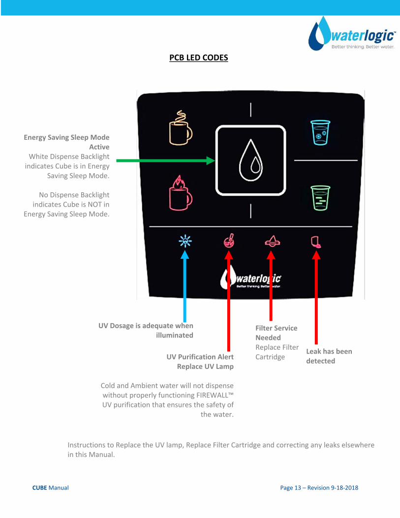
PCB LED CODES
Energy Saving Sleep Mode Active
White Dispense Backlight indicates Cube is in Energy
Saving Sleep Mode.
No Dispense Backlight indicates Cube is NOT in
Energy Saving Sleep Mode.
UV Dosage is adequate when illuminated
UV Purification Alert Replace UV Lamp
Cold and Ambient water will not dispense without properly functioning FIREWALL™ UV purification that ensures the safety of
the water.
Filter Service Needed Replace Filter Cartridge
Leak has been detected
Instructions to Replace the UV lamp, Replace Filter Cartridge and correcting any leaks elsewhere in this Manual.
CUBE Manual Page 14 – Revision 9‐18‐2018
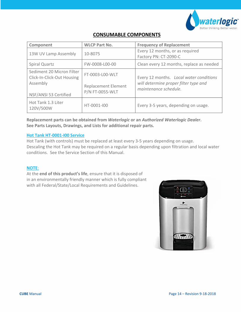
CONSUMABLE COMPONENTS
Component WLCP Part No. Frequency of Replacement
13W UV Lamp Assembly 10‐8075 Every 12 months, or as required Factory PN: CT‐2090‐C
Spiral Quartz FW‐0008‐L00‐00 Clean every 12 months, replace as needed
Sediment 20 Micron Filter Click‐In‐Click‐Out Housing Assembly NSF/ANSI 53 Certified
FT‐0003‐L00‐WLT Replacement Element P/N FT‐0055‐WLT
Every 12 months. Local water conditions will determine proper filter type and maintenance schedule.
Hot Tank 1.3 Liter 120V/500W
HT‐0001‐I00 Every 3‐5 years, depending on usage.
Replacement parts can be obtained from Waterlogic or an Authorized Waterlogic Dealer. See Parts Layouts, Drawings, and Lists for additional repair parts.
Hot Tank HT‐0001‐I00 Service Hot Tank (with controls) must be replaced at least every 3‐5 years depending on usage. Descaling the Hot Tank may be required on a regular basis depending upon filtration and local water conditions. See the Service Section of this Manual.
NOTE: At the end of this product’s life, ensure that it is disposed of in an environmentally friendly manner which is fully compliant with all Federal/State/Local Requirements and Guidelines.
CUBE Manual Page 15 – Revision 9‐18‐2018
SERVICE REQUIREMENTS WARNING! Read and understand the contents of this manual before attempting to service CUBE. Failure to follow the instructions in this manual could result in death, serious personal injury, or severe property damage. Only trained and qualified technicians should attempt to install, maintain, or service Waterlogic Equipment.
Materials Needed:
Personal Protective Equipment. Rubber or Nitrile Safety Gloves and Protective Eyewear
Phillips Screwdriver.
Replacement filter cartridge(s)
New 13‐Watt UV lamp
Water Pitcher or Container to collect water from the faucet
5‐gallon container or drain basin
Sanitizer ‐ Household Bleach (5.25% Sodium Hypochlorite) or Citric Acid Based Cleaner
1. WARNING! HIGH VOLTAGE ELECTRICAL HAZARD. Unplug before inspection and service.
1. Visually inspect all electrical and water connections for signs of wear or damage.
2. Waterlogic recommends changing the UV Lamp every 12 months.
WARNING! ULTRAVIOLET RADIATION. Protect your skin and eyes against ultraviolet rays. Never look directly at an operating UV light. Disconnect before removing UV Lamp.
CAUTION! UV LAMPS ARE HAZARDOUS. Lamps are considered Hazardous Waste and must be disposed of accordingly. Refer to Product MSDS sheet for details. CAUTION! UV SYSTEM IS FRAGILE. Never handle the UV Lamp or Quartz Sleeve with bare hands. UV Lamp and Quartz Sleeve must be free of oils and contaminants to ensure proper operation. Use a soft non‐abrasive cloth to clean.
3. Ensure there is adequate (minimum of 2”) clearance around the Cube Water Treatment System and clean the condenser grill and compressor fan to provide efficient cooling system operation.
4. Sanitize the cold tank per instructions in the pre‐installation procedures.
Clean and sanitize external surfaces of the Cube Water Treatment System. Use soap and water or chemicals that are compatible with ABS plastic and will not damage or degrade the product surfaces.
Remove and clean the faucet. Replace as needed.
WARNING! SANITIZER MAY CONTAIN HAZARDOUS CHEMICALS. Use of proper personal protective equipment such as rubber gloves and eye protection is required.
CUBE Manual Page 16 – Revision 9‐18‐2018
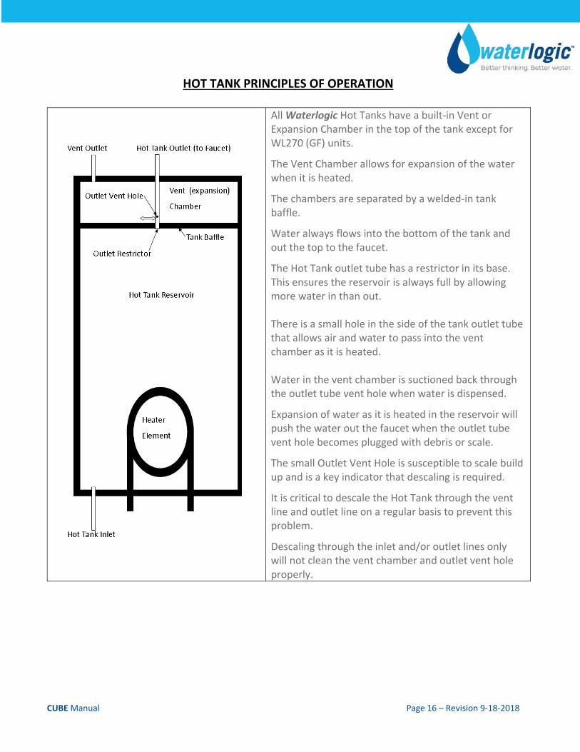
HOT TANK PRINCIPLES OF OPERATION
All Waterlogic Hot Tanks have a built‐in Vent or Expansion Chamber in the top of the tank except for WL270 (GF) units.
The Vent Chamber allows for expansion of the water when it is heated.
The chambers are separated by a welded‐in tank baffle.
Water always flows into the bottom of the tank and out the top to the faucet.
The Hot Tank outlet tube has a restrictor in its base. This ensures the reservoir is always full by allowing more water in than out. There is a small hole in the side of the tank outlet tube that allows air and water to pass into the vent chamber as it is heated. Water in the vent chamber is suctioned back through the outlet tube vent hole when water is dispensed.
Expansion of water as it is heated in the reservoir will push the water out the faucet when the outlet tube vent hole becomes plugged with debris or scale.
The small Outlet Vent Hole is susceptible to scale build up and is a key indicator that descaling is required.
It is critical to descale the Hot Tank through the vent line and outlet line on a regular basis to prevent this problem.
Descaling through the inlet and/or outlet lines only will not clean the vent chamber and outlet vent hole properly.
CUBE Manual Page 17 – Revision 9‐18‐2018
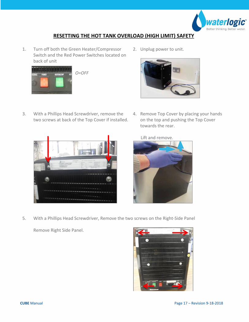
RESETTING THE HOT TANK OVERLOAD (HIGH LIMIT) SAFETY
1. Turn off both the Green Heater/Compressor Switch and the Red Power Switches located on back of unit
O=OFF
2. Unplug power to unit.
3. With a Phillips Head Screwdriver, remove the two screws at back of the Top Cover if installed.
4. Remove Top Cover by placing your hands on the top and pushing the Top Cover towards the rear.
Lift and remove.
5. With a Phillips Head Screwdriver, Remove the two screws on the Right‐Side Panel Remove Right Side Panel.
CUBE Manual Page 18 – Revision 9‐18‐2018
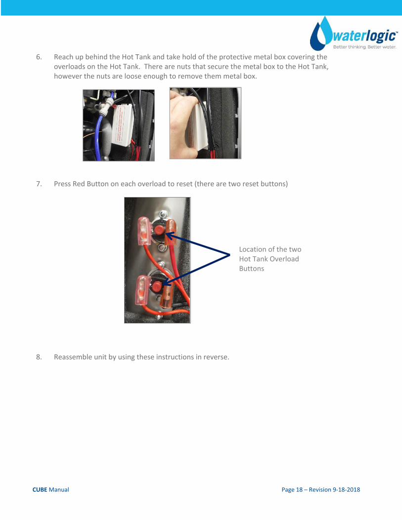
6. Reach up behind the Hot Tank and take hold of the protective metal box covering the overloads on the Hot Tank. There are nuts that secure the metal box to the Hot Tank, however the nuts are loose enough to remove them metal box.
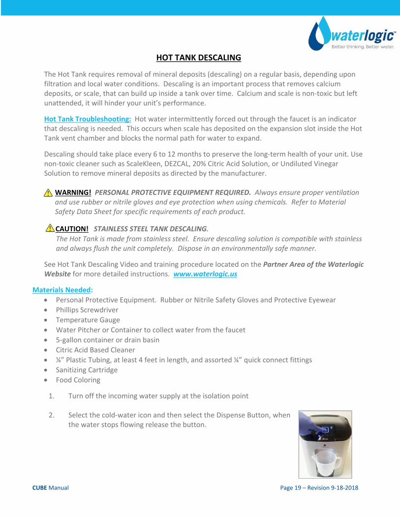
7. Press Red Button on each overload to reset (there are two reset buttons)
8. Reassemble unit by using these instructions in reverse.
Location of the two Hot Tank Overload Buttons
CUBE Manual Page 19 – Revision 9‐18‐2018
HOT TANK DESCALING
The Hot Tank requires removal of mineral deposits (descaling) on a regular basis, depending upon filtration and local water conditions. Descaling is an important process that removes calcium deposits, or scale, that can build up inside a tank over time. Calcium and scale is non‐toxic but left unattended, it will hinder your unit’s performance.
Hot Tank Troubleshooting: Hot water intermittently forced out through the faucet is an indicator that descaling is needed. This occurs when scale has deposited on the expansion slot inside the Hot Tank vent chamber and blocks the normal path for water to expand.
Descaling should take place every 6 to 12 months to preserve the long‐term health of your unit. Use non‐toxic cleaner such as ScaleKleen, DEZCAL, 20% Citric Acid Solution, or Undiluted Vinegar Solution to remove mineral deposits as directed by the manufacturer.
WARNING! PERSONAL PROTECTIVE EQUIPMENT REQUIRED. Always ensure proper ventilation and use rubber or nitrile gloves and eye protection when using chemicals. Refer to Material Safety Data Sheet for specific requirements of each product.
CAUTION! STAINLESS STEEL TANK DESCALING. The Hot Tank is made from stainless steel. Ensure descaling solution is compatible with stainless and always flush the unit completely. Dispose in an environmentally safe manner.
See Hot Tank Descaling Video and training procedure located on the Partner Area of the Waterlogic Website for more detailed instructions. www.waterlogic.us
Materials Needed:
Personal Protective Equipment. Rubber or Nitrile Safety Gloves and Protective Eyewear
Phillips Screwdriver
Temperature Gauge
Water Pitcher or Container to collect water from the faucet
5‐gallon container or drain basin
Citric Acid Based Cleaner
¼” Plastic Tubing, at least 4 feet in length, and assorted ¼” quick connect fittings
Sanitizing Cartridge
Food Coloring
1. Turn off the incoming water supply at the isolation point
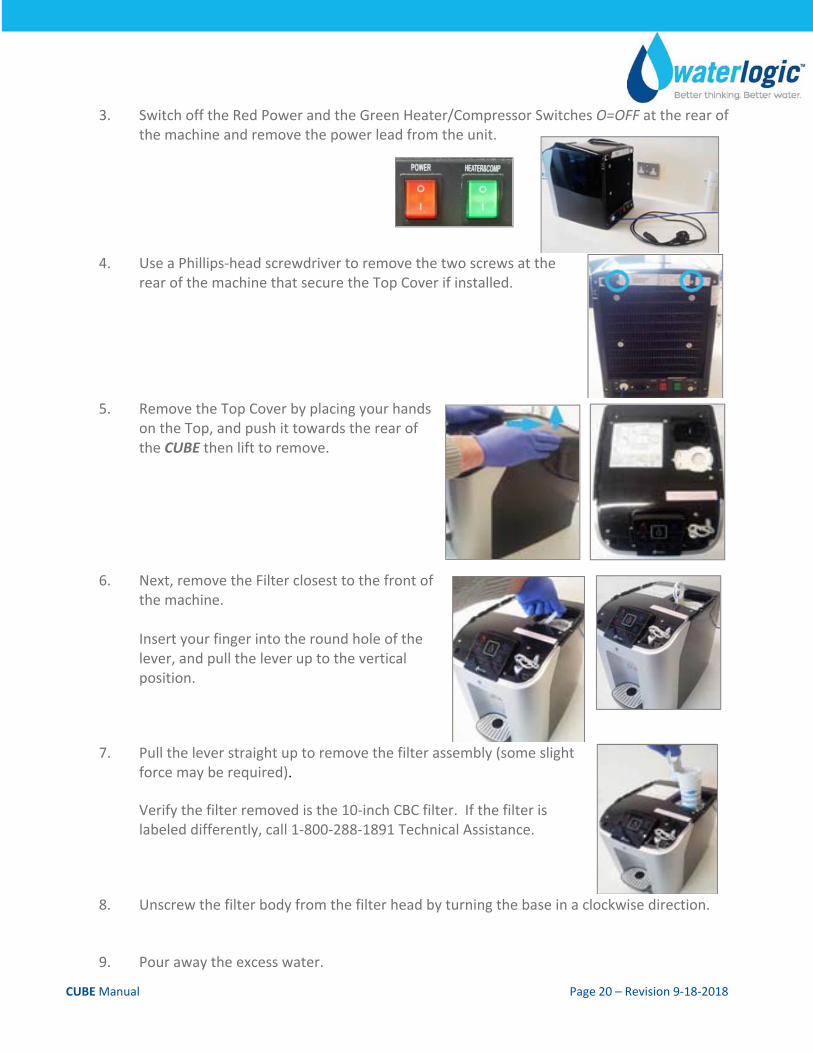
2. Select the cold‐water icon and then select the Dispense Button, when the water stops flowing release the button.
CUBE Manual Page 20 – Revision 9‐18‐2018
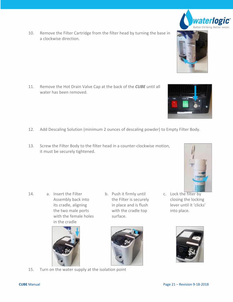
3. Switch off the Red Power and the Green Heater/Compressor Switches O=OFF at the rear of the machine and remove the power lead from the unit.
4. Use a Phillips‐head screwdriver to remove the two screws at the rear of the machine that secure the Top Cover if installed.
5. Remove the Top Cover by placing your hands on the Top, and push it towards the rear of the CUBE then lift to remove.
6. Next, remove the Filter closest to the front of the machine. Insert your finger into the round hole of the lever, and pull the lever up to the vertical position.
7. Pull the lever straight up to remove the filter assembly (some slight force may be required). Verify the filter removed is the 10‐inch CBC filter. If the filter is labeled differently, call 1‐800‐288‐1891 Technical Assistance.
8. Unscrew the filter body from the filter head by turning the base in a clockwise direction.
9. Pour away the excess water.
CUBE Manual Page 21 – Revision 9‐18‐2018
10. Remove the Filter Cartridge from the filter head by turning the base in a clockwise direction.
11. Remove the Hot Drain Valve Cap at the back of the CUBE until all water has been removed.
12. Add Descaling Solution (minimum 2 ounces of descaling powder) to Empty Filter Body.
13. Screw the Filter Body to the filter head in a counter‐clockwise motion, it must be securely tightened.
14. a. Insert the Filter Assembly back into its cradle, aligning the two male ports with the female holes in the cradle
b. Push it firmly until the Filter is securely in place and is flush with the cradle top surface.
c. Lock the filter by closing the locking lever until it ‘clicks’ into place.
15. Turn on the water supply at the isolation point
CUBE Manual Page 22 – Revision 9‐18‐2018
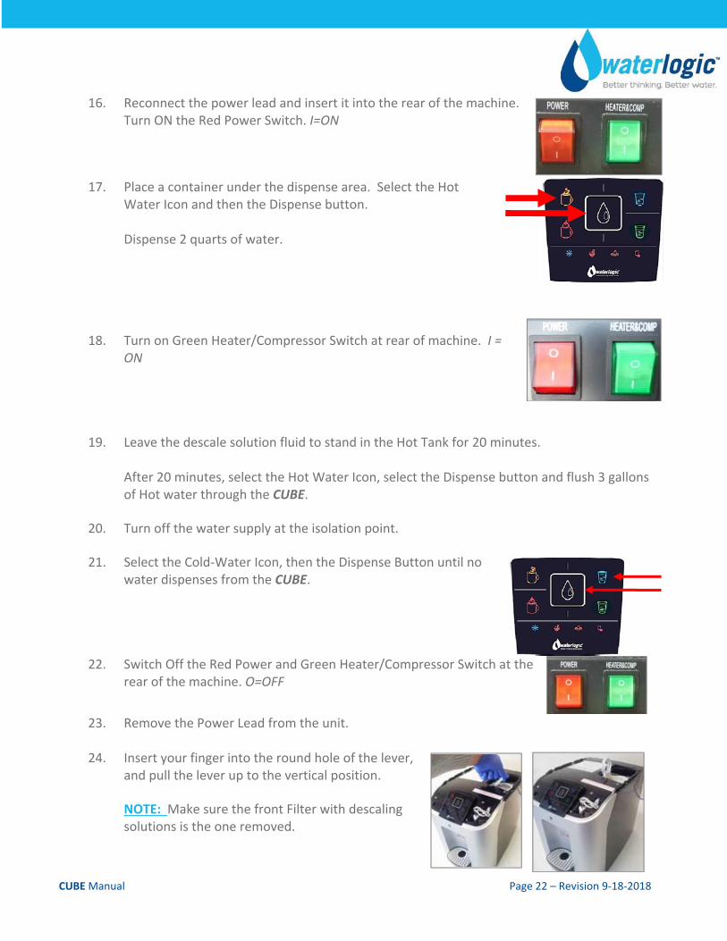
16. Reconnect the power lead and insert it into the rear of the machine. Turn ON the Red Power Switch. I=ON
17. Place a container under the dispense area. Select the Hot Water Icon and then the Dispense button. Dispense 2 quarts of water.
18. Turn on Green Heater/Compressor Switch at rear of machine. I = ON
19. Leave the descale solution fluid to stand in the Hot Tank for 20 minutes. After 20 minutes, select the Hot Water Icon, select the Dispense button and flush 3 gallons of Hot water through the CUBE.
20. Turn off the water supply at the isolation point.
21. Select the Cold‐Water Icon, then the Dispense Button until no water dispenses from the CUBE.
22. Switch Off the Red Power and Green Heater/Compressor Switch at the rear of the machine. O=OFF
23. Remove the Power Lead from the unit.
24. Insert your finger into the round hole of the lever, and pull the lever up to the vertical position. NOTE: Make sure the front Filter with descaling solutions is the one removed.
CUBE Manual Page 23 – Revision 9‐18‐2018
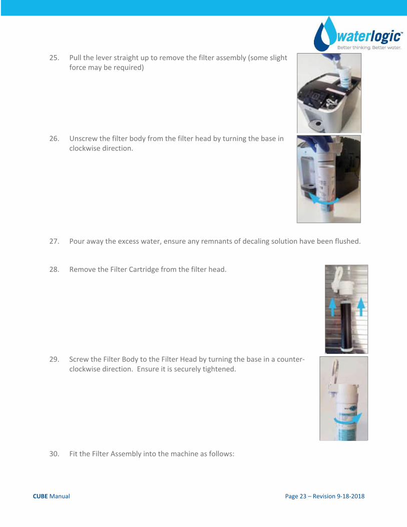
25. Pull the lever straight up to remove the filter assembly (some slight force may be required)
26. Unscrew the filter body from the filter head by turning the base in clockwise direction.
27. Pour away the excess water, ensure any remnants of decaling solution have been flushed.
28. Remove the Filter Cartridge from the filter head.
29. Screw the Filter Body to the Filter Head by turning the base in a counter‐clockwise direction. Ensure it is securely tightened.
30. Fit the Filter Assembly into the machine as follows:
CUBE Manual Page 24 – Revision 9‐18‐2018
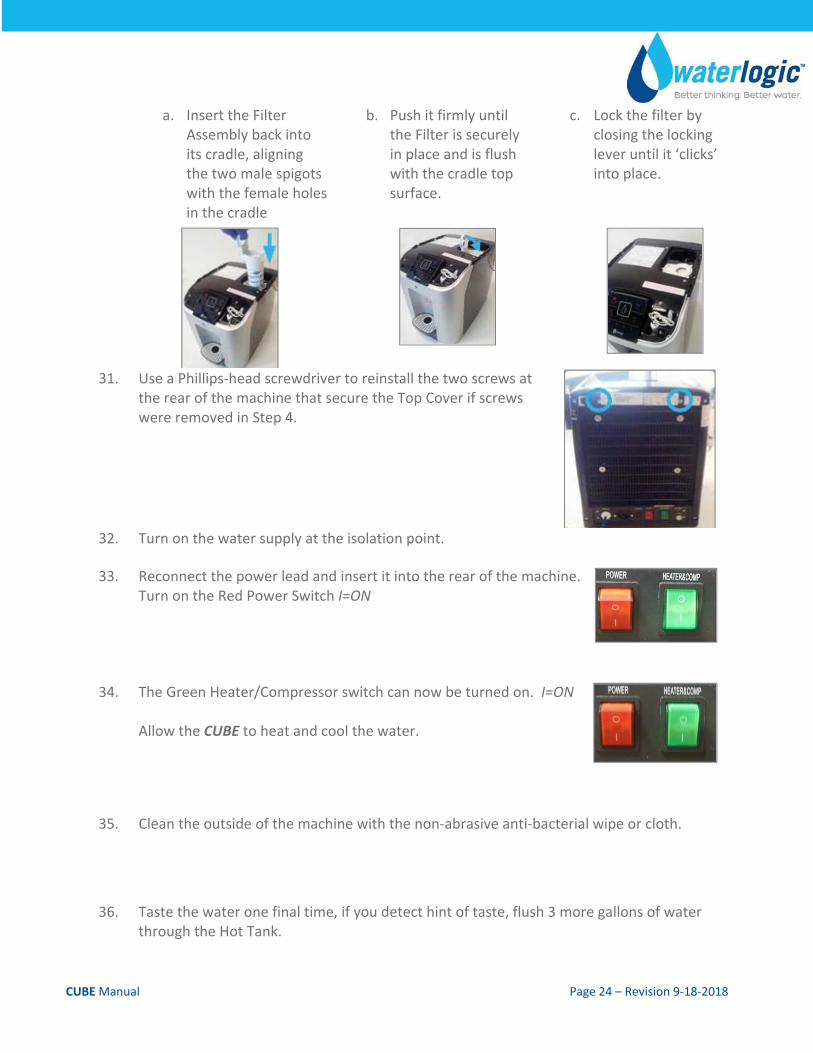
a. Insert the Filter Assembly back into its cradle, aligning the two male spigots with the female holes in the cradle
b. Push it firmly until the Filter is securely in place and is flush with the cradle top surface.
c. Lock the filter by closing the locking lever until it ‘clicks’ into place.
31. Use a Phillips‐head screwdriver to reinstall the two screws at the rear of the machine that secure the Top Cover if screws were removed in Step 4.
32. Turn on the water supply at the isolation point.
33. Reconnect the power lead and insert it into the rear of the machine. Turn on the Red Power Switch I=ON
34. The Green Heater/Compressor switch can now be turned on. I=ON Allow the CUBE to heat and cool the water.
35. Clean the outside of the machine with the non‐abrasive anti‐bacterial wipe or cloth.
36. Taste the water one final time, if you detect hint of taste, flush 3 more gallons of water
through the Hot Tank.
CUBE Manual Page 25 – Revision 9‐18‐2018
WARNING! HOT WATER HAZARD. Unit Produces Very Hot Water and Steam. Always use insulated and chemically compatible containers and let unit cool down before draining the Hot Tank to avoid injury.
CAUTION! REPLACE HOT TANK EVERY 3‐5 YEARS. The Hot Tank and its controls should be replaced a minimum of every three to five years to ensure efficient operation.
WARNING! REINSTALL ALL PANELS AND COVERS. Always reinstall all panels, protective covers, and fasteners after servicing equipment. Failure to do so could result in severe personal injury and will void the certifications and warranty of the equipment.
CUBE Manual Page 26 – Revision 9‐18‐2018
FILTER REPLACEMENT
Filters should be configured to optimize your system. Filters need to be configured and specified to do the job given the local water conditions, usage, maintenance schedule, and placement restrictions.
In order for our filters to perform as represented and to provide the best quality water possible, it is essential that filters be replaced periodically. The frequency of filter changes depends on your water quality and your water usage. For example, if there is a lot of sediment and/or particles in your water, then you will have to change your filters more frequently than a location with little to no sediment. Be sure to replace your filters whenever you notice a decline in the performance, whether it is a drop‐in flow rate and/or pressure or an unusual taste in the water.
WARNING! Read and understand the contents of this manual before attempting to service CUBE. Failure to follow the instructions in this manual could result in death, serious personal injury, or severe property damage. Only trained and qualified technicians should attempt to install, maintain, or service Waterlogic Equipment.
Materials Needed:
Phillips Screwdriver.
Replacement filter cartridge(s)
Water Pitcher or Container to collect water from the faucet
5‐gallon container or drain basin
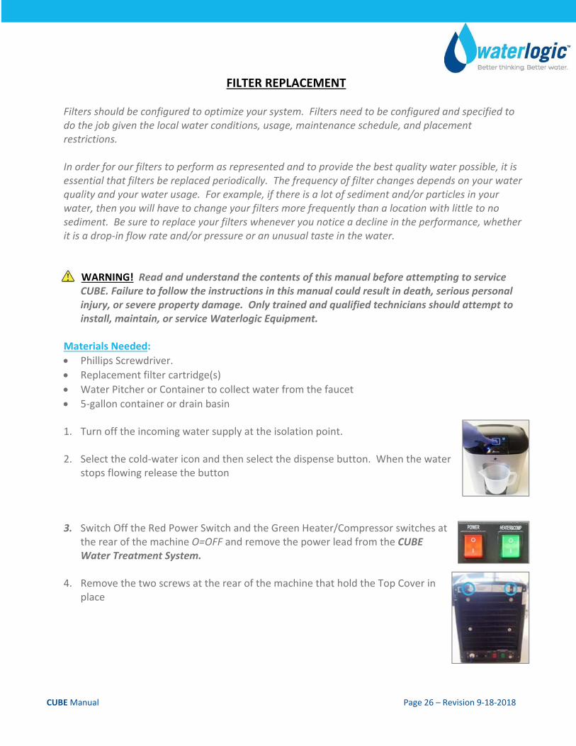
1. Turn off the incoming water supply at the isolation point.
2. Select the cold‐water icon and then select the dispense button. When the water stops flowing release the button
3. Switch Off the Red Power Switch and the Green Heater/Compressor switches at the rear of the machine O=OFF and remove the power lead from the CUBE Water Treatment System.
4. Remove the two screws at the rear of the machine that hold the Top Cover in place
CUBE Manual Page 27 – Revision 9‐18‐2018
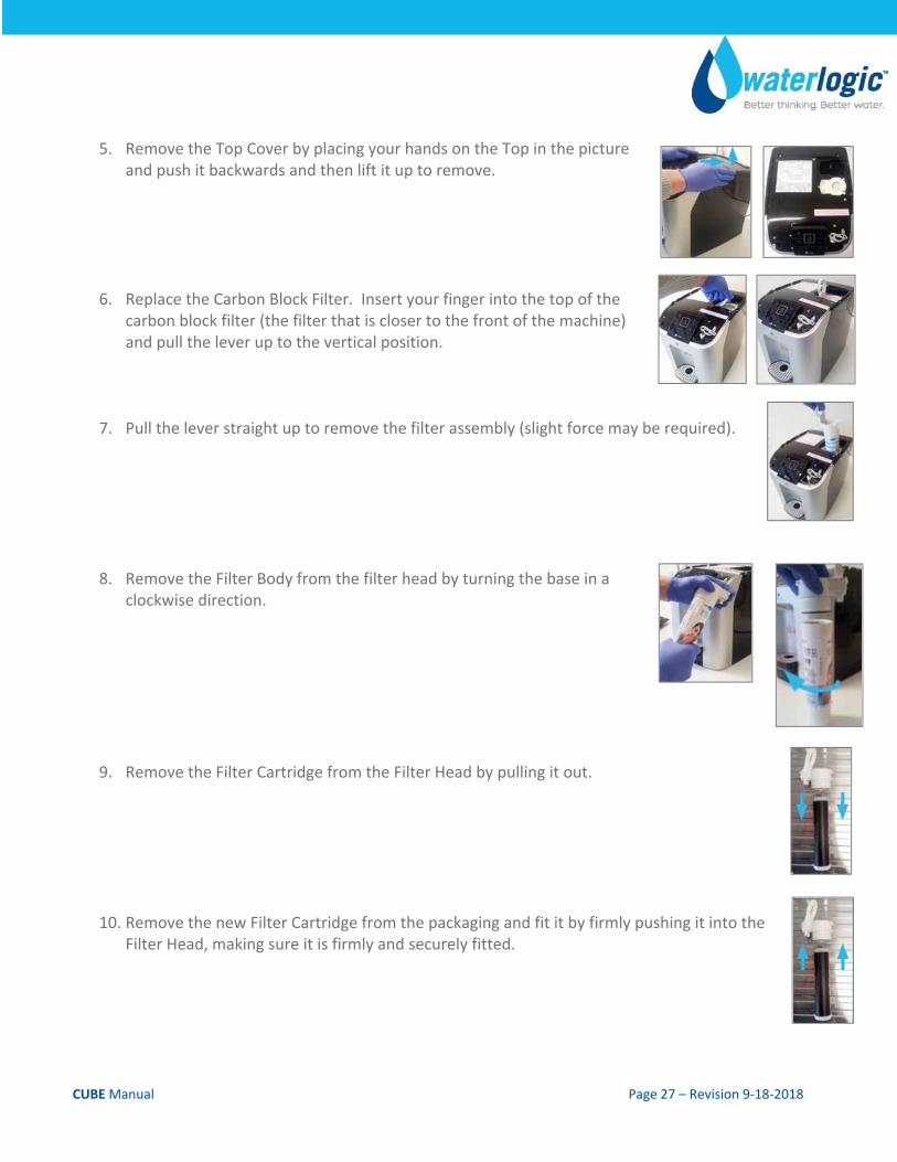
5. Remove the Top Cover by placing your hands on the Top in the picture
and push it backwards and then lift it up to remove.
6. Replace the Carbon Block Filter. Insert your finger into the top of the carbon block filter (the filter that is closer to the front of the machine) and pull the lever up to the vertical position.
7. Pull the lever straight up to remove the filter assembly (slight force may be required).
8. Remove the Filter Body from the filter head by turning the base in a clockwise direction.
9. Remove the Filter Cartridge from the Filter Head by pulling it out.
10. Remove the new Filter Cartridge from the packaging and fit it by firmly pushing it into the Filter Head, making sure it is firmly and securely fitted.
CUBE Manual Page 28 – Revision 9‐18‐2018
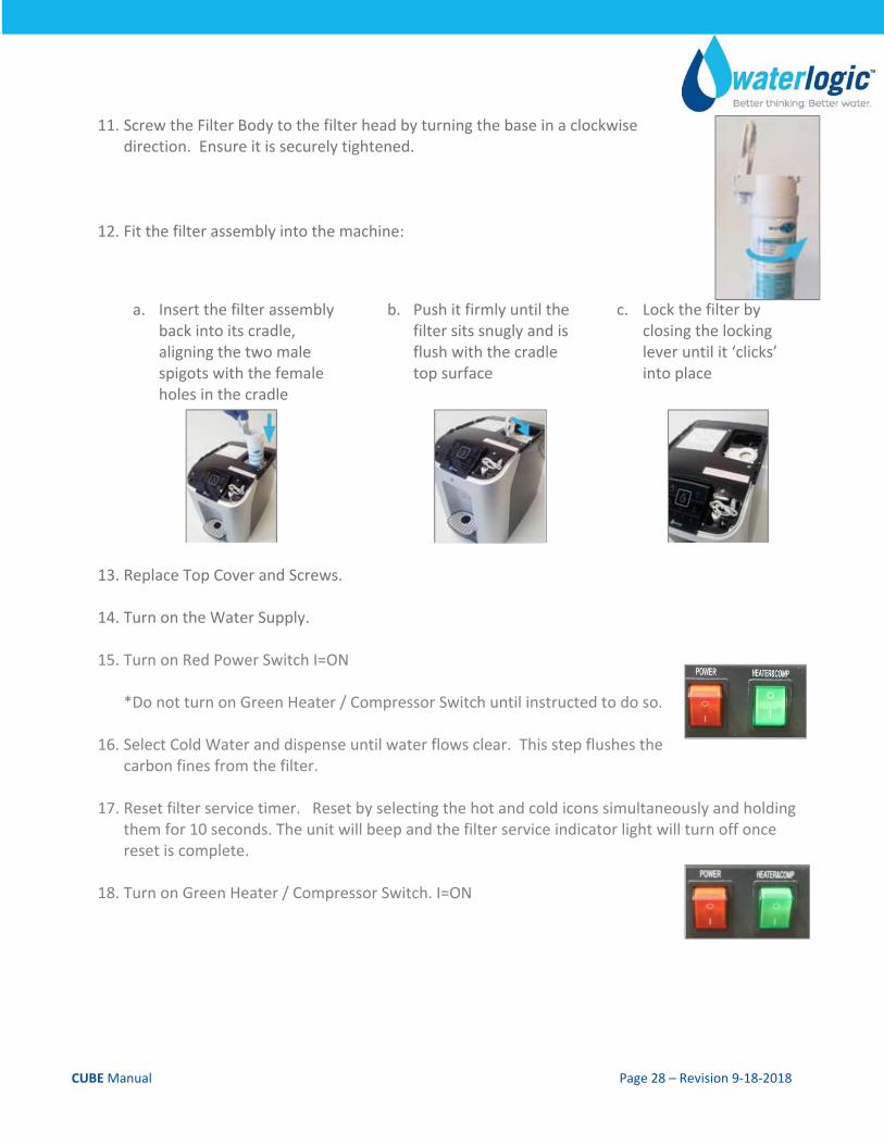
11. Screw the Filter Body to the filter head by turning the base in a clockwise direction. Ensure it is securely tightened.
12. Fit the filter assembly into the machine:
a. Insert the filter assembly back into its cradle, aligning the two male spigots with the female holes in the cradle
b. Push it firmly until the filter sits snugly and is flush with the cradle top surface
c. Lock the filter by closing the locking lever until it ‘clicks’ into place
13. Replace Top Cover and Screws.
14. Turn on the Water Supply.
15. Turn on Red Power Switch I=ON
*Do not turn on Green Heater / Compressor Switch until instructed to do so.
16. Select Cold Water and dispense until water flows clear. This step flushes the carbon fines from the filter.
17. Reset filter service timer. Reset by selecting the hot and cold icons simultaneously and holding them for 10 seconds. The unit will beep and the filter service indicator light will turn off once reset is complete.
18. Turn on Green Heater / Compressor Switch. I=ON
CUBE Manual Page 29 – Revision 9‐18‐2018
UV LAMP REPLACEMENT
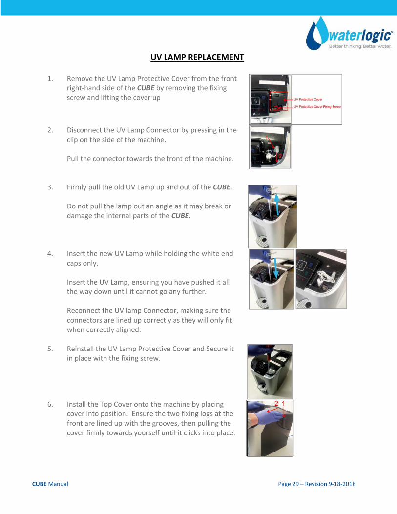
1. Remove the UV Lamp Protective Cover from the front right‐hand side of the CUBE by removing the fixing screw and lifting the cover up
2. Disconnect the UV Lamp Connector by pressing in the clip on the side of the machine. Pull the connector towards the front of the machine.
3. Firmly pull the old UV Lamp up and out of the CUBE. Do not pull the lamp out an angle as it may break or damage the internal parts of the CUBE.
4. Insert the new UV Lamp while holding the white end caps only. Insert the UV Lamp, ensuring you have pushed it all the way down until it cannot go any further. Reconnect the UV lamp Connector, making sure the connectors are lined up correctly as they will only fit when correctly aligned.
5. Reinstall the UV Lamp Protective Cover and Secure it in place with the fixing screw.
6. Install the Top Cover onto the machine by placing cover into position. Ensure the two fixing logs at the front are lined up with the grooves, then pulling the cover firmly towards yourself until it clicks into place.
CUBE Manual Page 30 – Revision 9‐18‐2018
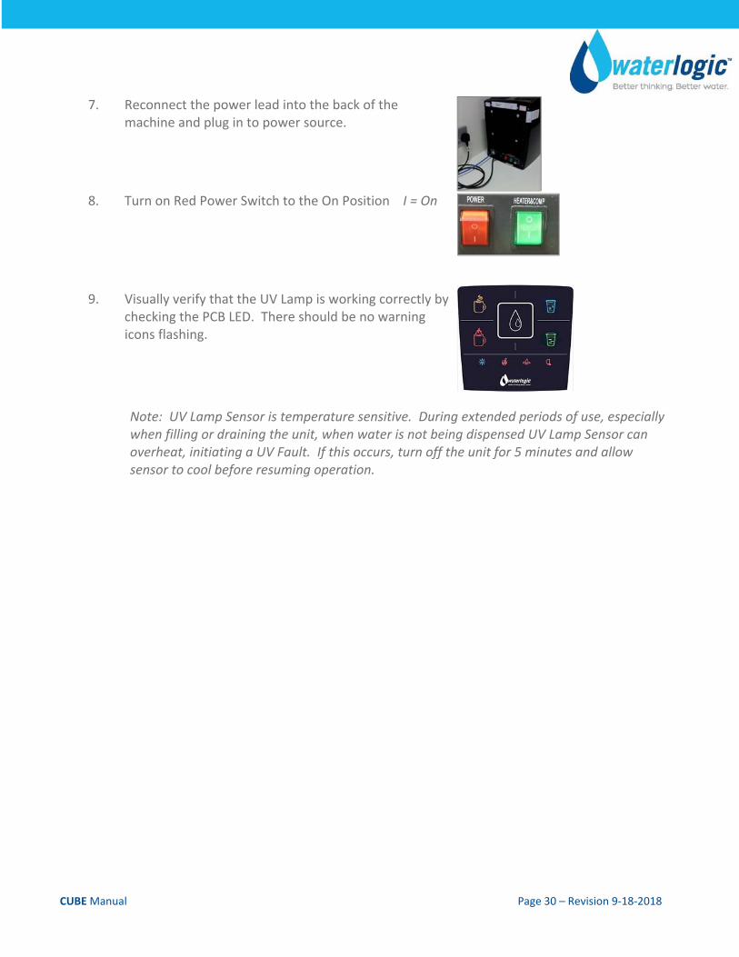
7. Reconnect the power lead into the back of the machine and plug in to power source.
8. Turn on Red Power Switch to the On Position I = On
9. Visually verify that the UV Lamp is working correctly by checking the PCB LED. There should be no warning icons flashing.
Note: UV Lamp Sensor is temperature sensitive. During extended periods of use, especially when filling or draining the unit, when water is not being dispensed UV Lamp Sensor can overheat, initiating a UV Fault. If this occurs, turn off the unit for 5 minutes and allow sensor to cool before resuming operation.
CUBE Manual Page 31 – Revision 9‐18‐2018
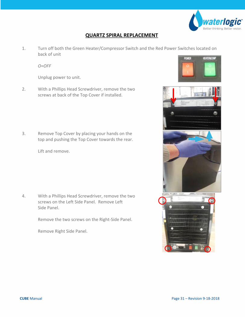
QUARTZ SPIRAL REPLACEMENT
1. Turn off both the Green Heater/Compressor Switch and the Red Power Switches located on back of unit O=OFF Unplug power to unit.
2. With a Phillips Head Screwdriver, remove the two screws at back of the Top Cover if installed.
3. Remove Top Cover by placing your hands on the top and pushing the Top Cover towards the rear. Lift and remove.
4. With a Phillips Head Screwdriver, remove the two screws on the Left Side Panel. Remove Left Side Panel. Remove the two screws on the Right‐Side Panel. Remove Right Side Panel.
CUBE Manual Page 32 – Revision 9‐18‐2018
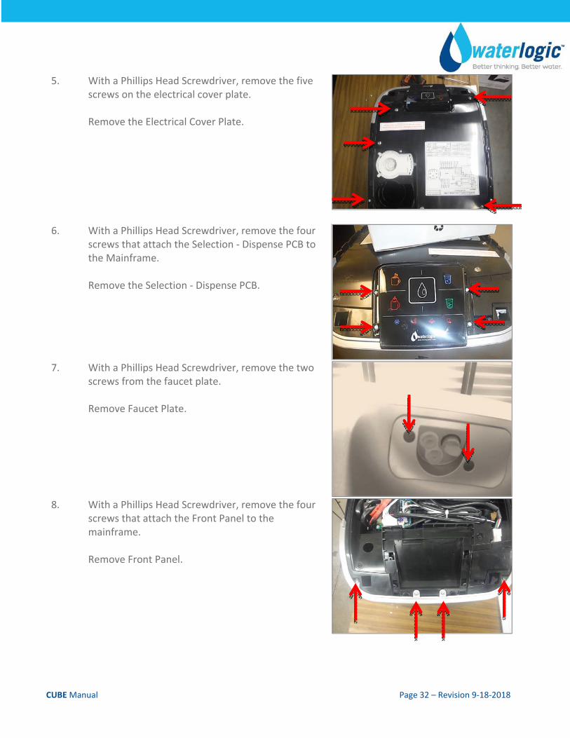
5. With a Phillips Head Screwdriver, remove the five screws on the electrical cover plate. Remove the Electrical Cover Plate.
6. With a Phillips Head Screwdriver, remove the four screws that attach the Selection ‐ Dispense PCB to the Mainframe. Remove the Selection ‐ Dispense PCB.
7. With a Phillips Head Screwdriver, remove the two screws from the faucet plate. Remove Faucet Plate.
8. With a Phillips Head Screwdriver, remove the four screws that attach the Front Panel to the mainframe. Remove Front Panel.
CUBE Manual Page 33 – Revision 9‐18‐2018
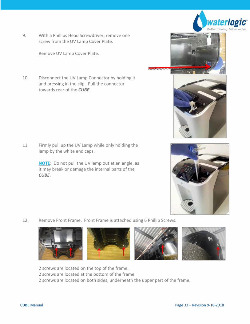
9. With a Phillips Head Screwdriver, remove one screw from the UV Lamp Cover Plate. Remove UV Lamp Cover Plate.
10. Disconnect the UV Lamp Connector by holding it and pressing in the clip. Pull the connector towards rear of the CUBE.
11. Firmly pull up the UV Lamp while only holding the lamp by the white end caps. NOTE: Do not pull the UV lamp out at an angle, as it may break or damage the internal parts of the CUBE.
12. Remove Front Frame. Front Frame is attached using 6 Phillip Screws.
2 screws are located on the top of the frame. 2 screws are located at the bottom of the frame. 2 screws are located on both sides, underneath the upper part of the frame.
CUBE Manual Page 34 – Revision 9‐18‐2018
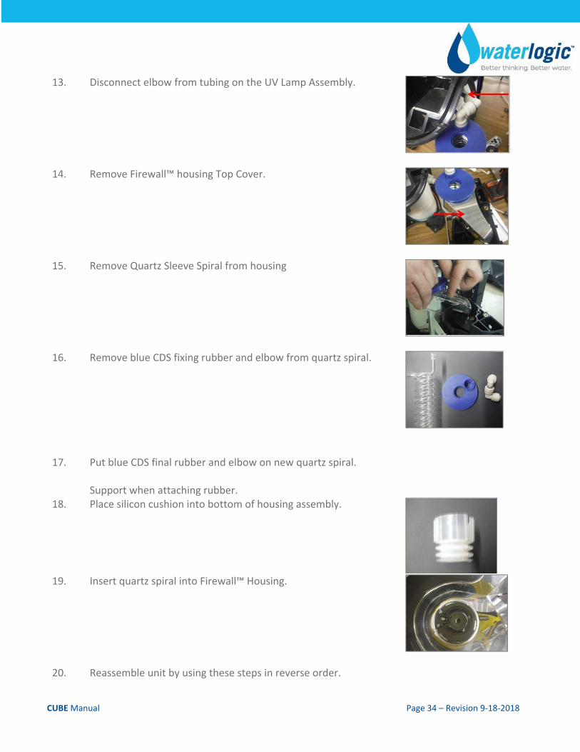
13. Disconnect elbow from tubing on the UV Lamp Assembly.
14. Remove Firewall™ housing Top Cover.
15. Remove Quartz Sleeve Spiral from housing
16. Remove blue CDS fixing rubber and elbow from quartz spiral.
17. Put blue CDS final rubber and elbow on new quartz spiral. Support when attaching rubber.
18. Place silicon cushion into bottom of housing assembly.
19. Insert quartz spiral into Firewall™ Housing.
20. Reassemble unit by using these steps in reverse order.
CUBE Manual Page 35 – Revision 9‐18‐2018
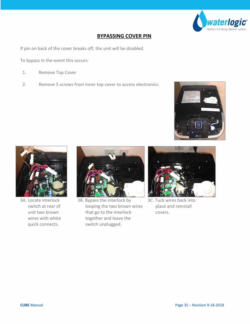
BYPASSING COVER PIN If pin on back of the cover breaks off, the unit will be disabled. To bypass in the event this occurs: 1. Remove Top Cover
2. Remove 5 screws from inner top cover to access electronics:
3A. Locate interlock switch at rear of unit two brown wires with white quick connects.
3B. Bypass the interlock by looping the two brown wires that go to the interlock together and leave the switch unplugged.
3C. Tuck wires back into place and reinstall covers.
CUBE Manual Page 36 – Revision 9‐18‐2018
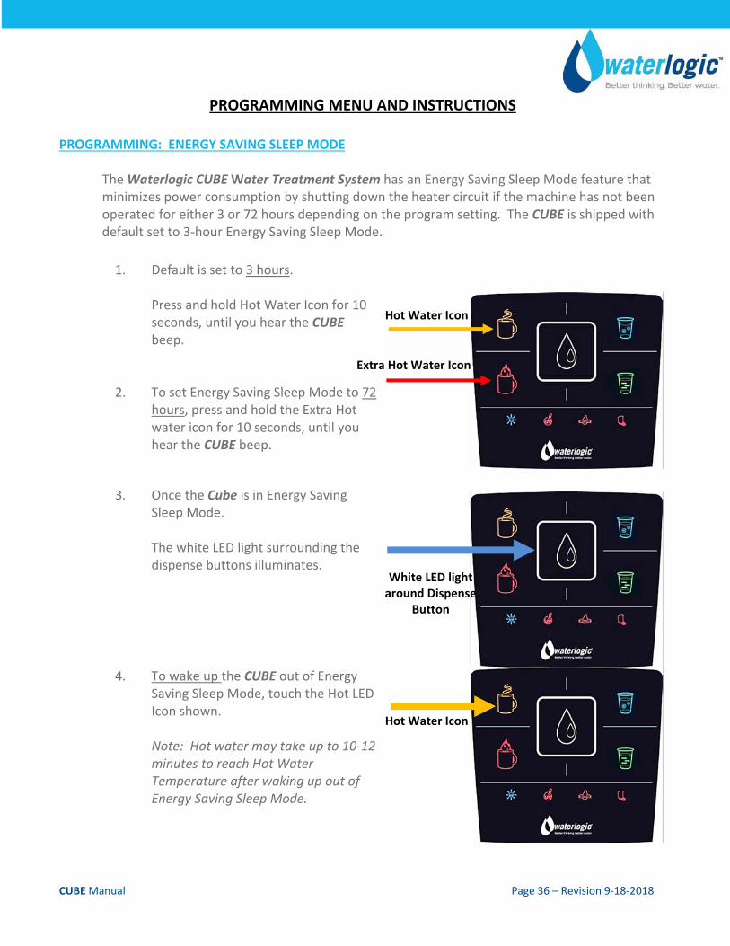
PROGRAMMING MENU AND INSTRUCTIONS PROGRAMMING: ENERGY SAVING SLEEP MODE
The Waterlogic CUBE Water Treatment System has an Energy Saving Sleep Mode feature that minimizes power consumption by shutting down the heater circuit if the machine has not been operated for either 3 or 72 hours depending on the program setting. The CUBE is shipped with default set to 3‐hour Energy Saving Sleep Mode.
1. Default is set to 3 hours. Press and hold Hot Water Icon for 10 seconds, until you hear the CUBE beep.
2. To set Energy Saving Sleep Mode to 72 hours, press and hold the Extra Hot water icon for 10 seconds, until you hear the CUBE beep.
3. Once the Cube is in Energy Saving Sleep Mode. The white LED light surrounding the dispense buttons illuminates.
4. To wake up the CUBE out of Energy Saving Sleep Mode, touch the Hot LED Icon shown. Note: Hot water may take up to 10‐12 minutes to reach Hot Water Temperature after waking up out of Energy Saving Sleep Mode.
Hot Water Icon
Extra Hot Water Icon
White LED light around Dispense
Button
Hot Water Icon
CUBE Manual Page 37 – Revision 9‐18‐2018
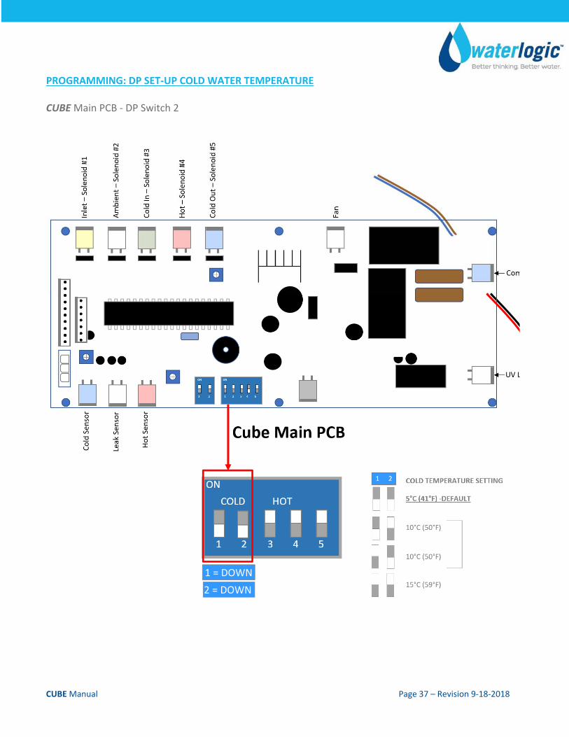
PROGRAMMING: DP SET‐UP COLD WATER TEMPERATURE CUBE Main PCB ‐ DP Switch 2
1 = DOWN
2 = DOWN
CUBE Manual Page 38 – Revision 9‐18‐2018
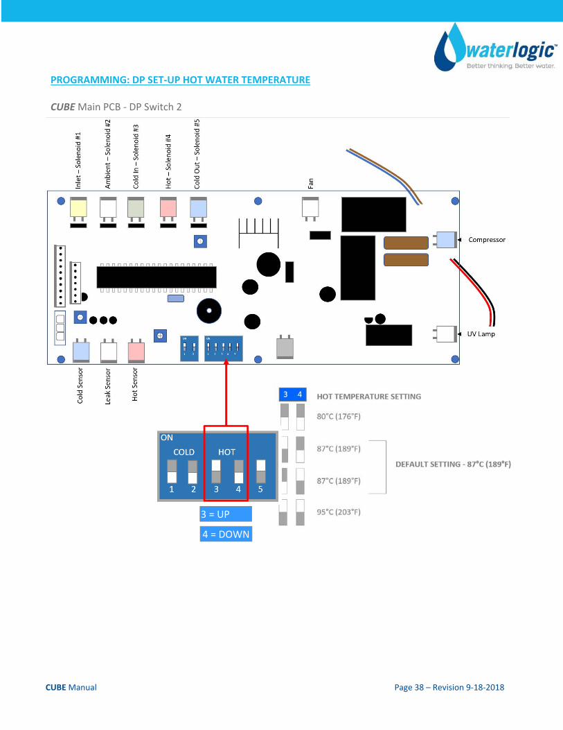
PROGRAMMING: DP SET‐UP HOT WATER TEMPERATURE CUBE Main PCB ‐ DP Switch 2
3 = UP
4 = DOWN
CUBE Manual Page 39 – Revision 9‐18‐2018
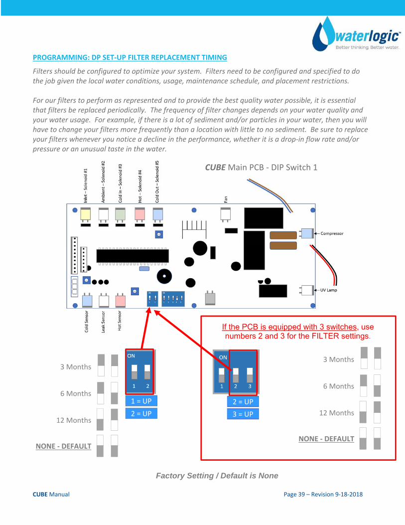
PROGRAMMING: DP SET‐UP FILTER REPLACEMENT TIMING
Filters should be configured to optimize your system. Filters need to be configured and specified to do the job given the local water conditions, usage, maintenance schedule, and placement restrictions. For our filters to perform as represented and to provide the best quality water possible, it is essential that filters be replaced periodically. The frequency of filter changes depends on your water quality and your water usage. For example, if there is a lot of sediment and/or particles in your water, then you will have to change your filters more frequently than a location with little to no sediment. Be sure to replace your filters whenever you notice a decline in the performance, whether it is a drop‐in flow rate and/or pressure or an unusual taste in the water.
Factory Setting / Default is None
CUBEMain PCB ‐ DIP Switch 1
If the PCB is equipped with 3 switches, use numbers 2 and 3 for the FILTER settings.
2 = UP
3 = UP
1 = UP
2 = UP
3 Months
6 Months
12 Months
NONE ‐ DEFAULT
3 Months
6 Months
12 Months
NONE ‐ DEFAULT
CUBE Manual Page 40 – Revision 9‐18‐2018
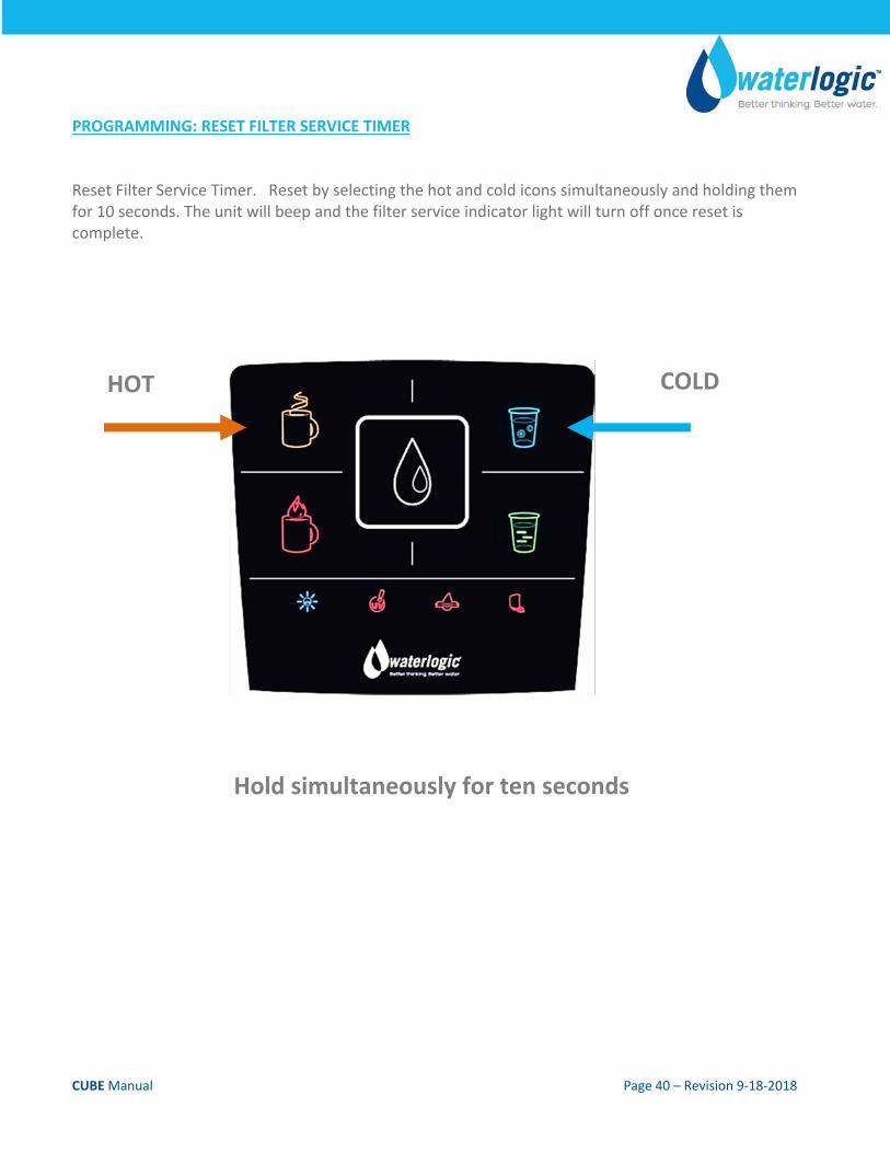
PROGRAMMING: RESET FILTER SERVICE TIMER Reset Filter Service Timer. Reset by selecting the hot and cold icons simultaneously and holding them for 10 seconds. The unit will beep and the filter service indicator light will turn off once reset is complete.
HOT COLD
Hold simultaneously for ten seconds
CUBE Manual Page 41 – Revision 9‐18‐2018
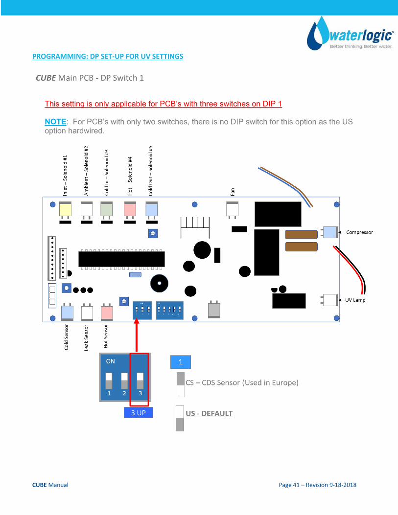
PROGRAMMING: DP SET‐UP FOR UV SETTINGS
CUBE Main PCB ‐ DP Switch 1
This setting is only applicable for PCB’s with three switches on DIP 1 NOTE: For PCB’s with only two switches, there is no DIP switch for this option as the US option hardwired.
3 UP
CUBE Manual Page 42 – Revision 9‐18‐2018
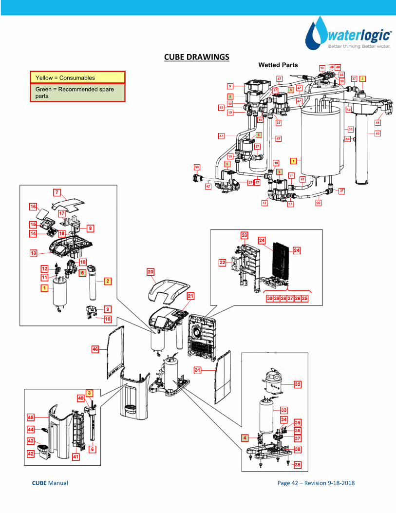
CUBE DRAWINGS
Yellow = Consumables
Green = Recommended spare parts
Wetted Parts
CUBE Manual Page 43 – Revision 9‐18‐2018
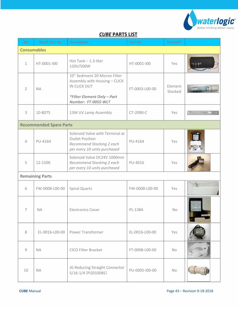
CUBE PARTS LIST
No WLCP Part No. Description Part No Stocked?
Consumables
1 HT‐0001‐I00 Hot Tank – 1.3‐liter 120V/500W
HT‐0001‐I00 Yes
2 NA
10” Sediment 20 Micron Filter Assembly with Housing – CLICK IN CLICK OUT *Filter Element Only – Part Number: FT‐0055‐WLT
FT‐0003‐L00‐00 Element Stocked
3 10‐8075 13W UV Lamp Assembly CT‐2090‐C Yes
Recommended Spare Parts
4 PU‐4164
Solenoid Valve with Terminal at Outlet Position Recommend Stocking 2 each per every 10 units purchased
PU‐4164 Yes
5 12‐1500 Solenoid Valve DC24V 1000mm Recommend Stocking 2 each per every 10 units purchased
PU‐4016 Yes
Remaining Parts
6 FW‐0008‐L00‐00 Spiral Quartz FW‐0008‐L00‐00 Yes
7 NA Electronics Cover PL‐1384 No
8 EL‐0016‐L00‐00 Power Transformer EL‐0016‐L00‐00 Yes
9 NA CICO Filter Bracket FT‐0008‐L00‐00 No
10 NA JG Reducing Straight Connector
5/16‐1/4(PI201008S) PU‐0005‐I00‐00 No
CUBE Manual Page 44 – Revision 9‐18‐2018
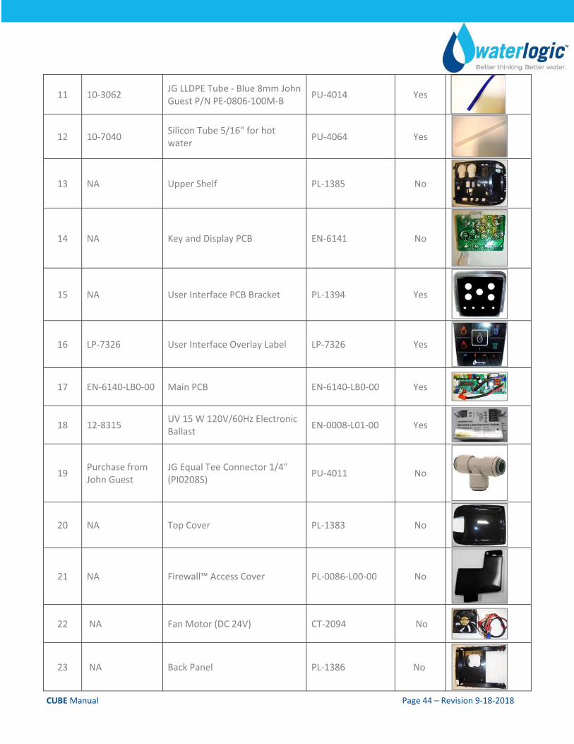
11 10‐3062 JG LLDPE Tube ‐ Blue 8mm John Guest P/N PE‐0806‐100M‐B
PU‐4014 Yes
12 10‐7040 Silicon Tube 5/16" for hot water
PU‐4064 Yes
13 NA Upper Shelf PL‐1385 No
14 NA Key and Display PCB EN‐6141 No
15 NA User Interface PCB Bracket PL‐1394 Yes
16 LP‐7326 User Interface Overlay Label LP‐7326 Yes
17 EN‐6140‐LB0‐00 Main PCB EN‐6140‐LB0‐00 Yes
18 12‐8315 UV 15 W 120V/60Hz Electronic Ballast
EN‐0008‐L01‐00 Yes
19 Purchase from John Guest
JG Equal Tee Connector 1/4" (PI0208S)
PU‐4011 No
20 NA Top Cover PL‐1383 No
21 NA Firewall™ Access Cover PL‐0086‐L00‐00 No
22 NA Fan Motor (DC 24V) CT‐2094 No
23 NA Back Panel PL‐1386 No
CUBE Manual Page 45 – Revision 9‐18‐2018
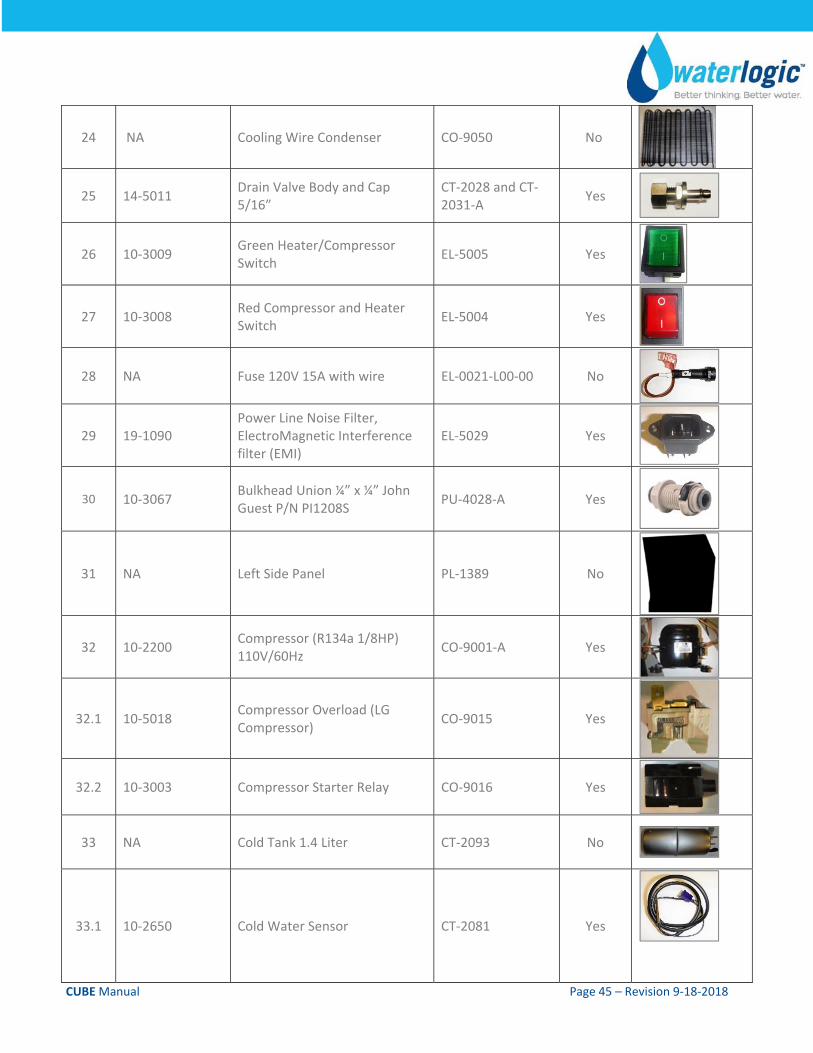
24 NA Cooling Wire Condenser CO‐9050 No
25 14‐5011 Drain Valve Body and Cap 5/16”
CT‐2028 and CT‐2031‐A
Yes
26 10‐3009 Green Heater/Compressor Switch
EL‐5005 Yes
27 10‐3008 Red Compressor and Heater Switch
EL‐5004 Yes
28 NA Fuse 120V 15A with wire EL‐0021‐L00‐00 No
29 19‐1090 Power Line Noise Filter, ElectroMagnetic Interference filter (EMI)
EL‐5029 Yes
30 10‐3067 Bulkhead Union ¼” x ¼” John Guest P/N PI1208S
PU‐4028‐A Yes
31 NA Left Side Panel PL‐1389 No
32 10‐2200 Compressor (R134a 1/8HP) 110V/60Hz
CO‐9001‐A Yes
32.1 10‐5018 Compressor Overload (LG Compressor)
CO‐9015 Yes
32.2 10‐3003 Compressor Starter Relay CO‐9016 Yes
33 NA Cold Tank 1.4 Liter CT‐2093 No
33.1 10‐2650 Cold Water Sensor CT‐2081 Yes
CUBE Manual Page 46 – Revision 9‐18‐2018
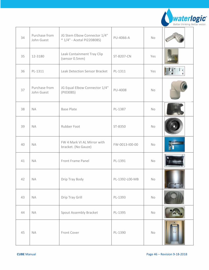
34 Purchase from John Guest
JG Stem Elbow Connector 1/4" * 1/4" ‐ Acetal PI220808S)
PU‐4066‐A No
35 12‐3180 Leak Containment Tray Clip (sensor 0.5mm)
ST‐8207‐CN Yes
36 PL‐1311 Leak Detection Sensor Bracket PL‐1311 Yes
37 Purchase from John Guest
JG Equal Elbow Connector 1/4" (PI0308S)
PU‐4008 No
38 NA Base Plate PL‐1387 No
39 NA Rubber Foot ST‐8350 No
40 NA FW 4 Mark VI AL Mirror with bracket. (No Gauze)
FW‐0013‐I00‐00 No
41 NA Front Frame Panel PL‐1391 No
42 NA Drip Tray Body PL‐1392‐L00‐MB No
43 NA Drip Tray Grill PL‐1393 No
44 NA Spout Assembly Bracket PL‐1395 No
45 NA Front Cover PL‐1390 No
CUBE Manual Page 47 – Revision 9‐18‐2018
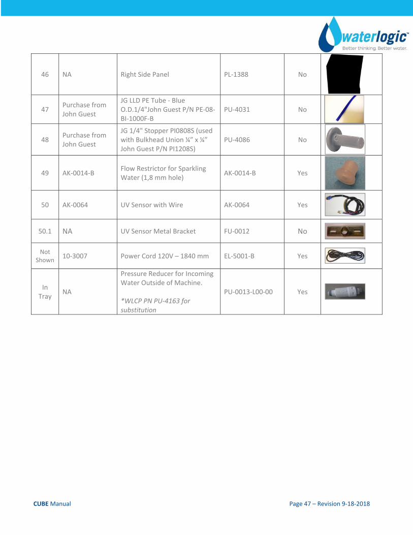
46 NA Right Side Panel PL‐1388 No
47 Purchase from John Guest
JG LLD PE Tube ‐ Blue O.D.1/4"John Guest P/N PE‐08‐BI‐1000F‐B
PU‐4031 No
48 Purchase from John Guest
JG 1/4" Stopper PI0808S (used with Bulkhead Union ¼” x ¼” John Guest P/N PI1208S)
PU‐4086 No
49 AK‐0014‐B Flow Restrictor for Sparkling Water (1,8 mm hole)
AK‐0014‐B Yes
50 AK‐0064 UV Sensor with Wire AK‐0064 Yes
50.1 NA UV Sensor Metal Bracket FU‐0012 No
Not Shown
10‐3007 Power Cord 120V – 1840 mm EL‐5001‐B Yes
In Tray
NA
Pressure Reducer for Incoming Water Outside of Machine. *WLCP PN PU‐4163 for substitution
PU‐0013‐L00‐00 Yes
CUBE Manual Page 48 – Revision 9‐18‐2018
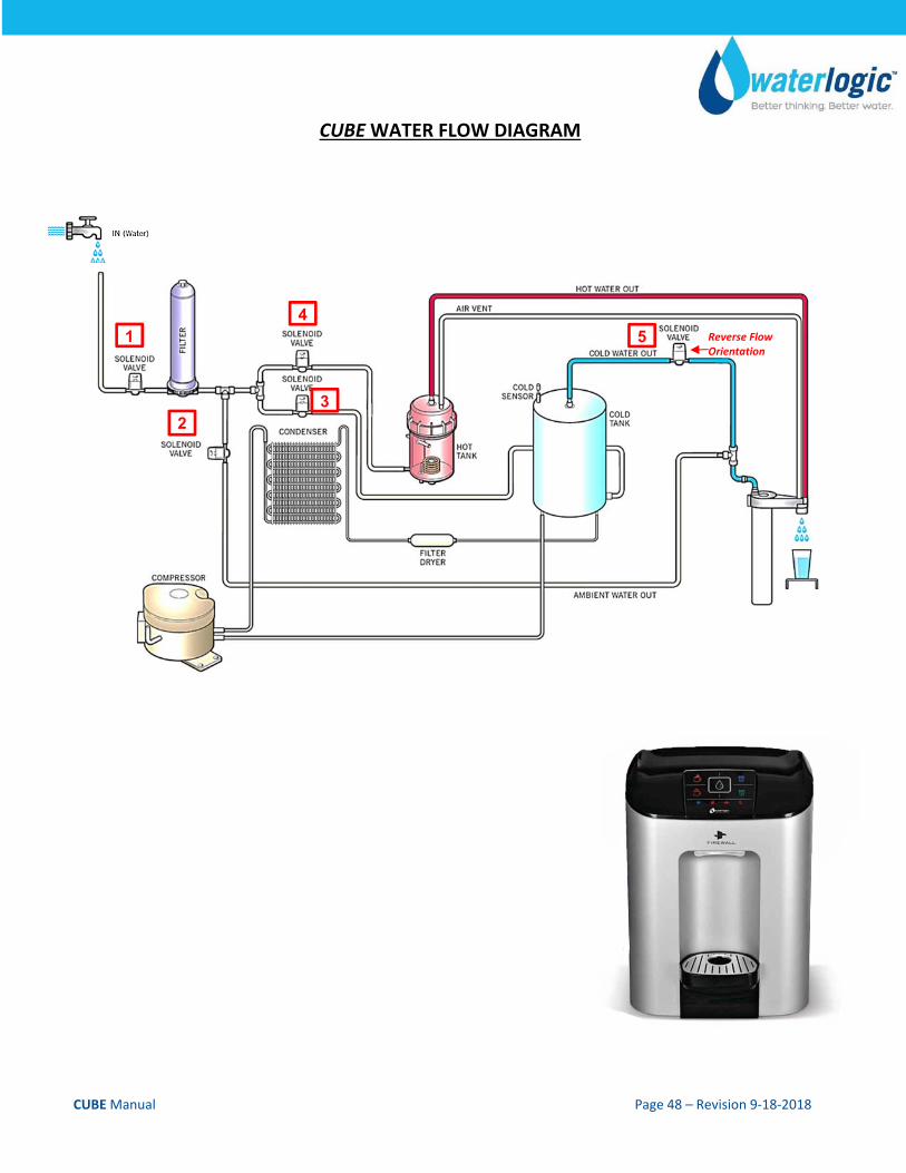
CUBE WATER FLOW DIAGRAM
Reverse Flow Orientation
1 5
3 2
4
CUBE Manual Page 49 – Revision 9‐18‐2018
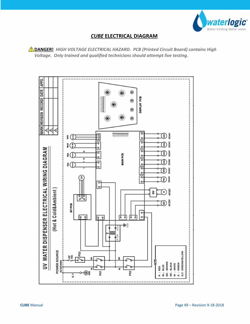
CUBE ELECTRICAL DIAGRAM
DANGER! HIGH VOLTAGE ELECTRICAL HAZARD. PCB (Printed Circuit Board) contains High Voltage. Only trained and qualified technicians should attempt live testing.