Embed Size (px)
Citation preview

PORTLAND CEMENT CONCRETE PAVING
FIELD INSPECTION 2014
TECHNICAL TRAINING & CERTIFICATION PROGRAM
HIGHWAY DIVISION CONSTRUCTION OFFICE


1
Chapter 1 Introduction ....................................................................................... 1-1
A. Technical Assistance ......................................................................................................... 1-1
Chapter 2 Concrete .............................................................................................. 2-1
A. Concrete Materials ............................................................................................................ 2-3
1. Aggregates ..................................................................................................................... 2-3
2. Cement .......................................................................................................................... 2-4
3. Water ............................................................................................................................. 2-8
4. Admixtures .................................................................................................................... 2-9
B. Concrete Terms ............................................................................................................... 2-11
C. Concrete Properties ......................................................................................................... 2-12
1. Strength ....................................................................................................................... 2-12
2. Air Content .................................................................................................................. 2-14
3. Slump .......................................................................................................................... 2-15
4. Water/Cement Ratio .................................................................................................... 2-16
5. Temperature ................................................................................................................ 2-16
6. Unit Weight ................................................................................................................. 2-17
7. Workability.................................................................................................................. 2-18
D. Concrete Mixes ............................................................................................................... 2-18
Chapter 3 Subgrade and Bases ........................................................................... 3-1
A. Subgrade Treatment (Stabilization) .................................................................................. 3-1
1. Select Soil ...................................................................................................................... 3-1
2. Special Backfill ............................................................................................................. 3-2
3. Polymer Grid ................................................................................................................. 3-2
4. Fly Ash Stabilization ..................................................................................................... 3-3
B. Base and Subbase .............................................................................................................. 3-4
1. Granular Subbase .......................................................................................................... 3-5
2. Modified Subbase .......................................................................................................... 3-6
3. Special Backfill ............................................................................................................. 3-7
Chapter 4 Design .................................................................................................. 4-1
A. Project Plans...................................................................................................................... 4-1
1. Title Sheet, Location Map, & Legend - A Sheets ......................................................... 4-1
2. Typical Cross Sections- B Sheets.................................................................................. 4-1
3. Estimate of Quantities and General Information- C Sheets .......................................... 4-1

2
4. Mainline Plan and Profile Sheets- D Sheets.................................................................. 4-1
5. Side Road Plan and Profile Sheets- E Sheets ................................................................ 4-1
6. Interchange Geometrics- K Sheets ................................................................................ 4-2
7. Intersection Geometrics- L Sheets ................................................................................ 4-2
B. Joints ................................................................................................................................. 4-2
1. Joint Types .................................................................................................................... 4-3
2. Saw cuts......................................................................................................................... 4-6
Chapter 5 Equipment .......................................................................................... 5-1
A. Trimmer and Roller........................................................................................................... 5-1
B. Transporting Vehicles ....................................................................................................... 5-3
1. Dump Trucks ................................................................................................................. 5-4
2. Agitator Trucks ............................................................................................................. 5-5
3. Ready Mix Trucks ......................................................................................................... 5-6
C. Placing and Consolidating ................................................................................................ 5-7
1. Belt Placer ..................................................................................................................... 5-7
2. Iowa Special .................................................................................................................. 5-9
3. Paver ............................................................................................................................ 5-10
D. Finishing ......................................................................................................................... 5-12
E. Texturing ......................................................................................................................... 5-14
1. Micro texture ............................................................................................................... 5-14
2. Macro texture .............................................................................................................. 5-15
F. Curing ............................................................................................................................. 5-16
G. Sawing............................................................................................................................. 5-18
1. Early entry saws .......................................................................................................... 5-18
2. Conventional Saws ...................................................................................................... 5-18
3. Span Saws ................................................................................................................... 5-19
H. Sealing............................................................................................................................. 5-19
Chapter 6 Prior to Paving ................................................................................... 6-1
A. Control .............................................................................................................................. 6-1
1. Survey Stakes ................................................................................................................ 6-2
2. Stringline ....................................................................................................................... 6-3
B. Proof Rolling ..................................................................................................................... 6-6
C. Check Subgrade ................................................................................................................ 6-6
D. Place Granular Subbase .................................................................................................... 6-7

3
E. Pad Line, Track Line, and Form Line ............................................................................. 6-10
F. Placement of Dowel Baskets .......................................................................................... 6-10
G. Paver Checks ................................................................................................................... 6-14
H. Determination of Subgrade and Subbase Elevations ...................................................... 6-16
1. Subgrade ...................................................................................................................... 6-16
2. Subbase........................................................................................................................ 6-18
Chapter 7 Paving Operations ............................................................................. 7-1
A. Wetting the Grade ............................................................................................................. 7-1
B. String Line Control ........................................................................................................... 7-1
C. Deposit and Spread Concrete ............................................................................................ 7-2
D. Place and Consolidate ....................................................................................................... 7-3
E. Finish................................................................................................................................. 7-3
1. Mechanical Floats ......................................................................................................... 7-4
2. Straight Edge and Hand Float ....................................................................................... 7-5
3. Edge Slump ................................................................................................................... 7-6
4. Water on the Surface ..................................................................................................... 7-7
5. Rumble Strips ................................................................................................................ 7-8
6. Marking Joints ............................................................................................................... 7-8
F. Texture .............................................................................................................................. 7-9
1. Microtexture .................................................................................................................. 7-9
2. Macrotexture ............................................................................................................... 7-10
G. Curing ............................................................................................................................. 7-11
H. Headers ........................................................................................................................... 7-12
I. Hand Pours ...................................................................................................................... 7-14
J. Cold Weather Protection ................................................................................................. 7-14
Chapter 8 Traffic Control & Safety ................................................................... 8-1
A. Traffic Control .................................................................................................................. 8-1
B. Safety ................................................................................................................................ 8-1
Chapter 9 Role of the Inspector During Paving ............................................... 9-1
A. Traffic Control .................................................................................................................. 9-2
B. Wetting the Grade ............................................................................................................. 9-3
C. Concrete Delivery ............................................................................................................. 9-4
1. Delivery Time ............................................................................................................... 9-4
2. Added Water ................................................................................................................. 9-5

4
3. Mixing ........................................................................................................................... 9-6
4. Clean Boxes................................................................................................................... 9-6
D. Placement .......................................................................................................................... 9-7
E. Concrete Testing ............................................................................................................... 9-7
1. Air Content .................................................................................................................... 9-7
2. Slump ............................................................................................................................ 9-9
3. Mix Temperatures ......................................................................................................... 9-9
F. Pavement Testing ............................................................................................................ 9-10
1. Edge Slump ................................................................................................................. 9-10
2. Pavement Width .......................................................................................................... 9-11
3. Cross Slope .................................................................................................................. 9-12
4. Depth Check ................................................................................................................ 9-13
5. Yield ............................................................................................................................ 9-14
G. Vibration ......................................................................................................................... 9-14
1. Frequency .................................................................................................................... 9-15
2. Paving Machine Vibration .......................................................................................... 9-15
3. Hand Held Vibration ................................................................................................... 9-18
H. Steel Placement ............................................................................................................... 9-18
1. Transverse Joints ......................................................................................................... 9-19
2. Longitudinal Joints ...................................................................................................... 9-20
3. “L” Joint Tie Bar Inspection ....................................................................................... 9-21
I. Finish............................................................................................................................... 9-21
J. Texture ............................................................................................................................ 9-23
K. Curing ............................................................................................................................. 9-24
L. Station Markers ............................................................................................................... 9-26
M. Concrete Strength ........................................................................................................ 9-27
1. Beams .......................................................................................................................... 9-27
2. Maturity ....................................................................................................................... 9-27
N. Date of Placement ........................................................................................................... 9-28
O. Monitor Contractor’s Haul Road .................................................................................... 9-29
P. Documentation ................................................................................................................ 9-31
Q. Monitor Contractor’s Housekeeping............................................................................... 9-31
R. Non-Compliance Notices ................................................................................................ 9-32
Chapter 10 Post Construction Checks ............................................................. 10-1

5
A. Saw Cuts ......................................................................................................................... 10-1
1. Early entry saws .......................................................................................................... 10-2
2. Conventional saws....................................................................................................... 10-3
B. Sealing Joints .................................................................................................................. 10-4
C. Texture ............................................................................................................................ 10-7
D. Smoothness ..................................................................................................................... 10-8
E. Strength ......................................................................................................................... 10-10
1. Beams ........................................................................................................................ 10-10
2. Maturity ..................................................................................................................... 10-12
F. Steel Placement ............................................................................................................. 10-14
G. Coring ........................................................................................................................... 10-15
1. Locating Cores .......................................................................................................... 10-15
2. Deficient Areas .......................................................................................................... 10-16
3. Length Evaluation ..................................................................................................... 10-16
4. Reporting ................................................................................................................... 10-17
5. MIT Scan T2 ............................................................................................................. 10-17
Chapter 11 Associated Construction Activities .............................................. 11-1
A. Earth Shoulder Construction. .......................................................................................... 11-1
B. Longitudinal Subdrains ................................................................................................... 11-2
1. Excavation ................................................................................................................... 11-2
2. Placement .................................................................................................................... 11-3
3. Porous Backfill ............................................................................................................ 11-4
4. Outlets ......................................................................................................................... 11-5
5. Restoring the shoulder ................................................................................................. 11-6
C. Granular Shoulders ......................................................................................................... 11-7
D. Paved Shoulders .............................................................................................................. 11-8
Chapter 12 Urban Paving ................................................................................. 12-1
A. Boxouts ........................................................................................................................... 12-2
B. Curbs ............................................................................................................................... 12-3
C. Hand Pours ...................................................................................................................... 12-4
1. Subgrade/Subbase Prep ............................................................................................... 12-5
2. Form Placement........................................................................................................... 12-5
3. Objects in or Under Pavement .................................................................................... 12-6
4. Concrete Placement ..................................................................................................... 12-7

6
5. Finishing ...................................................................................................................... 12-8
D. Obstructions .................................................................................................................... 12-8
E. Jointing ............................................................................................................................ 12-9
F. Access Locations .......................................................................................................... 12-10
Appendix A Resources .................................................................................... A-1
INSPECTOR’S TOOL KIT ..................................................................................................... A-2
PV-101 ..................................................................................................................................... A-3
Form E109 Sub Grade/Final Check....................................................................................... A-11
Pre-Pave Checklist ................................................................................................................. A-12
Form 830213 Project Information/Paver Inspection ............................................................. A-13
Form 830212 Ready Mix Concrete ....................................................................................... A-14
Form E137 PCC Pavement Field Page .................................................................................. A-15
Form E115 Air and Slump Tests ........................................................................................... A-16
Form E110 Depth Checks...................................................................................................... A-17
Form E111 PC Concrete Items Checklist .............................................................................. A-18
Form E114 PC Concrete Beams Record ............................................................................... A-19
Form E141 Maturity Record .................................................................................................. A-20
Form M142 Maturity Field Data Recording Sheet ................................................................ A-21
Form E140 Tining Depth Checks .......................................................................................... A-22
Form 800240 Daily PCC Plant Report .................................................................................. A-23
Form 821283 PCC Gradation Test Report – Verification ..................................................... A-24
Form 830245 Noncompliance Notice.................................................................................... A-25
Pavement Worksheet ............................................................................................................. A-26
Texture Check Worksheet ..................................................................................................... A-27
Joint Check Worksheet .......................................................................................................... A-28
Elevation Check Worksheet .................................................................................................. A-29
Appendix B PCC Paving Field Inspection Checklist .................................... B-1

C
HA
PT
ER
1
INT
RO
DU
CT
ION


1-1
Chapter 1 Introduction
This training manual has been prepared to provide guidance and instruction to inspectors
involved in the construction of Portland cement concrete (PCC) pavements. The important tasks
involved in this work are explained and proper procedures are described. The material is
targeted for those who have not had experience in PCC paving construction.
This manual is intended for use in any of three ways:
a text for a training class
a self-training manual
a reference to be used in the field
The manual is intended to help the inspector learn the various aspects of what is involved in a
PCC paving operation and also to become familiar with the duties that are a part of PCC paving
inspection responsibilities.
At the beginning of each section, references, when applicable, are given to:
Iowa Department of Transportation Standard Specification with the Specification Article
listed
Materials Instructional Memorandums (I.M.)
Standard Road Plans
Construction Manual Chapters
These references will enable the inspector to refer to those documents for more detailed
information. The actual documents are not included in this material because they are continually
being updated. Different versions may be applicable to different projects being constructed in
the same construction season. The project letting date will determine which Specification
Article, I.M., Standard Road Plan, or Construction Manual Chapter is applicable.
The manual is arranged to allow space for pictures adjacent to the text. This space may also be
used to make notes for future reference
A. Technical Assistance
For technical assistance or questions regarding the content of this publication, please contact
Kevin Merryman in the Iowa Department of Transportation Construction Office.
Kevin D. Merryman, P. E. PCC Field Engineer Office of Construction 800 Lincoln Way Ames, Iowa 50010 515-239-1848 800-262-0003 [email protected]

1-2
Inspection worksheets available online at:
http://www.iowadot.gov/construction/contract_admin.html
Specifications, Materials IMs, Road Standards, and Construction Manual available online
at:
http://www.iowadot.gov/erl/index.html
Iowa DOT standard forms available online at:
https://forms.iowadot.gov/BrowseForms.aspx

CH
AP
TE
R 2
CO
NC
RE
TE


2-1
Chapter 2 Concrete
Concrete consists of three basic components-aggregates (both sand and rock), cement, and water.
When mixed together, a chemical reaction occurs between the cement and water which
eventually causes the mixture to harden and form concrete. Concrete is one of the most versatile
construction materials and has tremendous compressive strength. It is widely used for both
pavements and structures.
Concrete used today is much more complicated than the three basic components. Many other
materials are included in a concrete mixture. Each is used for a specific purpose and is included
to improve the concrete. In the following sections, the ingredients commonly use for a concrete
paving mixture will be discussed in some detail in order to provide basic information as to what
they are and what their intended purpose is.
Figure 2-1 Basic components in concrete
After the components are mixed and become concrete, there are many properties that will
determine concrete quality as well as its ability to perform as it was intended and designed.
One thing that seems to be a universal misunderstanding is the misuse of the terms cement and
concrete.
Cement is the fine gray powder that holds the aggregates together.

2-2
Figure 2-2 Cement
Concrete is a mass of sand and rock bound together by cement.
Figure 2-3 Concrete

2-3
A. Concrete Materials
Concrete can be made from the three basic ingredients, but there are other materials and
properties that must be considered when designing a concrete mixture. It is important to
understand all of the materials and their properties because they can significantly affect
the properties of the concrete mixture which may affect the construction process.
1. Aggregates
Sections 4109, 4110, 4112, 4115, and 4117
I.M. T-203
The aggregates in a concrete mixture make up the largest portion of the volume of the
concrete; often about two thirds. The aggregates in standard Iowa DOT mixtures are
made up of two parts, the fine aggregate, which is the sand, and the coarse aggregate,
which is normally the gravel or crushed stone. The use of a third aggregate as a midsize
aggregate is being used more often when the contractor is allowed to design the concrete
mixture. The combination of the third aggregate, along with the coarse and fine
aggregates, normally produces stronger concrete while utilizing less cement. This often
results in more workable concrete for machine placement with less shrinkage.
There are two important aspects of aggregates. One is the gradation and the other is the
durability.
a. Gradation
Section 4109
A concrete mix basically consists of sand and rock of various sizes glued together
with a mixture of cement and water. The gradation of the aggregate, or distribution of
particle sizes, should meet the specifications outlined in Sections 4109 through 4117.
Quality Management Concrete (QM-C) specifications allow the contractor to
determine the gradation of the combined aggregates in the concrete mixture.
Many properties of a concrete mixture can be improved by utilizing a well graded,
combined gradation. This approach to mixture design strives for the aggregates to
have somewhat equal proportions of the various aggregate sizes. To the extent that
this can be accomplished with the materials available for a project, a number of
concrete properties can be improved:
Reduced cement content for equal strength
Improved workability and finishing
Reduced tendency for the coarse aggregate to separate from the sand-cement
mortar (segregation).

2-4
Figure 2-4 Well graded mixes have somewhat equal proportions of aggregate sizes
b. Durability
Durability is the other aspect of aggregates that must be considered in concrete
production. How the aggregate performs over time often determines how long the
pavement will last.
The Materials Office has geologists who evaluate aggregate sources. They evaluate
them in a number of ways and then approve them with an assigned durability rating.
The geologists monitor the performance of the aggregates based on service records of
existing pavements. They also perform physical and chemical tests. Based on
aggregate performance and testing results, they maintain a classification system for
aggregates that are allowed in concrete pavements and structures.
This information is contained in IM T-203. This classification needs to be checked
prior to construction to assure that the proposed aggregate sources are approved
sources and they are from the proper durability classification.
2. Cement
Section 4101, IM 401

2-5
Portland cement is the most important and the most expensive component in a concrete
mixture. It is the glue that holds the aggregates together and is the primary ingredient
that will determine the strength of the concrete.
The process used to make cement is not critical to understanding how it works or what
it’s properties are, but, it is worthwhile to know that cement is made up of limestone,
clay, and iron ore. These materials are combined and heated to very high temperatures to
form clinker. The clinker is ground with gypsum into a fine powder.
Figure 2-5 Limestone, clay, and iron ore heated to form clinker
Figure 2-6 Clinker is ground with gypsum to produce Portland cement
Strength is developed through a process called hydration. This is an exothermic reaction
meaning heat is produced and released. This begins when the cement particles come in
contact with water, and it continues as long as water is present. The hydration process
creates small needle-like crystals on the surface of the cement particle. The crystals grow
and attach to each other or to the surface of the aggregates and form a gel-like mass.
Clinker Gypsum Portland Cement

2-6
Because they continue to grow as long as water is present, it is important to retain the
water in the concrete as long as possible. This is why curing is so important.
Figure 2-7 Hydrated cement grains
Figure 2-8 Cement hydration crystals
Section 4101 describes the requirements for cements. Today we use not only pure
cements but also blended cements in concrete for paving. Blended cements are products
that consist of both Portland cement and a supplemental cementitious material. Both pure
cement and blended cements are used in concrete mixtures and either is considered as
cement when figuring cement content for a standard concrete mixture.
In Iowa the vast majority of concrete for all uses contains supplementary cementitious
materials. These are substituted for cement in the concrete mixture and serve a number
of useful purposes. Two types are commonly used in concrete paving:
a. Fly ash
b. Ground granulated blast furnace slag
a. Fly Ash
Section 4108, IM 491.17
Fly ash is a common mineral admixture used in most concrete paving mixtures. It is
a pozzolanic material that is a by-product of the burning of finely ground coal in
electricity generating power plants. It is a very fine, powdery material,
predominately silica, with particles almost totally spherical in shape.

2-7
Figure 2-9 Electricity generating power
plant
Figure 2-10 Fly ash is spherical in shape
Fly ash is known as a pozzolan. Pozzolans are finely divided, siliceous or
aluminosiliceous materials that react with water and calcium hydroxide released by
Portland cement hydration to form cementing compounds.
Fly ash is used in concrete to enhance a number of properties of the concrete. It also
results in a more economical mix since the price of fly ash is roughly a third of the
cost of the cement it replaces. Some of the benefits that can often be achieved by
using fly ash in concrete include:
Increased long term strength
Increased workability
Reduced heat of hydration
Reduced permeability
Reduced cost
The small size allows the particle to take up space that otherwise would be filled
with water and thereby leads to increased strength. The spherical shape of the fly ash
particle helps make the mix more workable.
Two Types of fly ash are specified in Section 4108: Class C fly ash and Class F fly
ash. The approved sources of each are listed in I.M. 491.17.
Class C fly ashes generally increase compressive strength at all ages and Class F fly
ashes only after 7 to 28 days. In conventional mix designs, both types of fly ash
normally retard the setting time of concrete although some Class C ashes have very
little retardation effect.
Class C fly ashes have both pozzolanic and cementitious properties, and Class F fly
ashes have only pozzolanic properties.
Generally one type of ash is predominantly available in various regions of the
country. In Iowa, Class C ash is commonly used

2-8
b. Ground Granulated Blast Furnace Slag (GGBFS)
Section 4108, IM 491.14
Ground granulated blast furnace slag (GGBFS) is a mineral admixture that is popular
in Iowa. It is a by-product of steel production. GGBFS is made from slag floating on
top of an iron blast furnace. The slag is tapped off and quenched in water to produce
a glassy sand-like material. This material is then ground to a fine white powder.
Figure 2-11 Slag is a by-product of steel
production
Figure 2-12 Slag is ground to a fine white powder
Like fly ash, GGBFS adds a number of very positive properties to concrete:
Increased workability
Increased strength
Decreased permeability
Increased sulfate resistance
Decreased alkali aggregate reaction potential
GGBFS is commonly blended or interground with cement to form IS(X) cement
where the X represents the percentage of GGBFS in the cement. For instance,
blended cement with 25% GGBFS replacement would be denoted as a IS(25).
GGBFS can also be added in the mixing process.
Combinations of Class C or F fly ash along with GGBFS can be used in a concrete
mixture. These types of mixes including two supplementary cementitious materials
along with Portland cement are called ternary mixes.
3. Water
Section 4102
The water used in batching concrete can come from almost any source. Each source must
be tested and approved if it is not potable. Often lakes or streams are used because they

2-9
are close to the project. This water must meet hardness, alkalinity, and acidity
requirements.
Workability issues arise during very hot weather. High temperature of the water can
contribute to this problem. There is no restriction on the water temperature but warm
water will add to the temperature of the concrete. High concrete temperatures can lead to
placement and durability problems.
4. Admixtures
Section 4103, IM 403
Admixtures are those ingredients in concrete, other than portland cement, pozzolans,
water, or aggregates, that are added to the mixture, normally immediately before or
during mixing. Admixtures can be classified by function and include:
Air Entraining admixtures
High/Mid Range Water Reducing admixtures
Retarding admixtures
Accelerating admixtures
Accelerators and high or mid range water reducers are not commonly used in paving.
Calcium Chloride is the most widely used accelerator and is used in patching work.
The effectiveness of an admixture depends upon such factors as type, brand, and amount
of cement, water content, aggregate shape, gradation, and proportions, mixing time,
slump, and concrete and air temperatures.
Desirable characteristics of concrete include being workable, finishable, strong, durable,
and wear resistant. These qualities can often be obtained easily and economically by the
selection of suitable materials rather than by resorting to admixtures (except air-
entraining admixtures when needed).
The major reasons for using admixtures are:
To reduce the cost of concrete construction
To achieve certain properties in concrete more effectively than by other means
To ensure the quality of concrete during the stages of mixing, transporting, placing,
and curing in adverse weather conditions
To overcome certain emergencies during concreting operation
Despite the above considerations, no admixture of any type or amount should be
considered a substitute for good concreting practice.
a. Air Entraining
Air-entraining admixtures are used to purposely entrain microscopic air bubbles in
concrete. One primary purpose of air-entrainment is to improve the durability of
concrete exposed to moisture during cycles of freezing and thawing.

2-10
Figure 2-13 Minute bubbles entrained in concrete
Entrained air also greatly improves concrete’s resistance to surface scaling caused by
chemical deicers. Another major benefit is to improve the workability of fresh
concrete. Segregation and bleeding are also reduced or eliminated.
Air-entrained concrete contains minute air bubbles that are distributed uniformly
throughout the cement paste. An air-entraining admixture is added directly to the
concrete materials either before or during mixing.
Today, air is entrained in concrete by using one of two types of products:
Neutralized Salt of Pine Wood Resins (normally called Vinsol resins)
Synthetic Detergents
NOTE: While entrained air imparts many beneficial properties in a concrete mixture,
there is a cost. For every 1% increase in entrained air content in a concrete mixture
there is approximately a 5% decrease in compressive strength.
b. Water Reducer
A water reducer is a substance that changes the electrical charges on cement particles.
This disperses the particles that naturally agglomerate. When this happens, water
particles that had been trapped by these particles are released. This is the same
process used by anti-static laundry products.
Water-reducing admixtures are used to reduce the quantity of mixing water required
to produce concrete of a certain slump, reduce water/cement ratio, or increase slump.
Typical water reducers reduce the water content by approximately 7% to 10%. High-
range water reducers reduce water content by 12% to 30%. Adding a water-reducing
admixture to a mix without reducing the water content can produce a mixture with a
much higher slump.

2-11
The rate of slump loss, however, is not reduced and in most cases is increased. Rapid
slump loss can occur and results in reduced workability and less time to place
concrete.
An increase in strength is generally obtained with water-reducing admixtures as the
water/cement ratio is reduced.
Many water-reducing admixtures can also retard the setting time of concrete. Some
are modified to give varying degrees of retardation while others do not significantly
affect the setting time. Some water-reducing admixtures such as lignosulfonates may
also entrain some air in concrete.
The effectiveness of water reducers in concrete is a function of their chemical
composition, concrete temperature, cement composition and fineness, cement content,
and the presence of other admixtures. Some water reducers are more effective in lean
mixtures and with cements of low alkali or low tricalcium aluminate contents.
c. Retarders
Retarding admixtures are used to retard the rate of setting of concrete. High
temperatures of fresh concrete (850
F to 900F and higher) are often the cause of an
increased rate of hardening that makes placing and finishing difficult. Without a
retarder, the primary method of counteracting this effect is to reduce the temperature
of the concrete by cooling the mixing water or the aggregates. Retarders do not
decrease the initial temperature of concrete.
Because most retarders also act as water reducers, they are frequently called water-
reducing retarders. Retarders may also entrain some air in concrete.
B. Concrete Terms
Concrete consists of three basic components - aggregate, cement, and water. However,
typical concrete mixtures can be further broken down into five basic constituents
consisting of cement, coarse aggregate, fine aggregate, water, and air (intermediate
aggregate can also be included when talking about QM-C paving mixes). There are
various terms that can be used to describe certain combinations of these constituents as
follows:
Aggregate: Often refers to the coarse, intermediate, and fine aggregates
Paste: The cement, water and air
Mortar: The fine aggregate, cement, water, and air

2-12
It is important to learn and understand each of these terms and what they mean when
working with concrete in order to avoid confusion when communicating with contractors,
suppliers, and/or other inspection staff.
C. Concrete Properties
There are several important properties of concrete that an inspector should know and
understand. Some of these properties are measurable and used in the acceptance process
while others are not measurable but are used in the decision making process during
construction. Following is a brief description of each of these properties.
1. Strength
Strength is a very important property of concrete. Many factors affect strength. Some of
those factors that affect strength must be considered when designing a concrete mixture
while others must be considered and watched during construction.
Concrete strength is measured in a number of different ways. The two most commonly
used for field applications in Iowa are compressive strength and flexural strength.
a. Compressive Strength
IM 315
Compressive strength is measured through the testing of cylinders or cores. This is
used in commercial work and most commonly in structural applications. Although
cylinders are cast during the construction of structures for highway construction, they
are not normally used in pavement construction projects in Iowa. Cores are taken to
determine the thickness of pavements, and in the past, those cores have been tested to
establish concrete strength for pavement design proposes.

2-13
Figure 2-14 Compression testing of cylinder
c. Flexural Strength
IM 316 & IM 328
Flexural strength is the traditional method used by the Iowa Department of
Transportation to monitor the concrete strength of pavements and to determine
opening time. It is measured using flexural beams cast as the pavement is
constructed. Currently the flexural strength required for opening a pavement to
traffic is based on the modulus of rupture of beams tested using center point loading.
Figure 2-15 Center point flexural testing of beam

2-14
Flexural beam strengths are also used when designing concrete pavements. These
tests are different, though, from the flexural test done for other purposes because they
are third point flexural tests. That means that they are tested with a different test
device and in a different manner than those tested traditionally using center point
loading. The values obtained from third point tests, as compared to center point tests,
will often be smaller, commonly about 85% of the center point strength.
Figure 2-16 Third point flexural testing of beam
2. Air Content
IM 318
In most cases, the air system within the concrete will determine its ability to resist
freeze/thaw deterioration. Therefore insuring adequate air content is of paramount
importance. Normally air content is checked in the field using a pressure meter which is
a test that determines the total air in the concrete. While this does not tell if the air
system is adequate to protect the concrete, normally it is the best test available, and it is
most commonly used.

2-15
Figure 2-17 Pressure meter and tools to perform air test
3. Slump
IM 317
Slump is an old test of concrete that was commonly used to give an indication of water
content in the mixture. Most practitioners today would agree that the test no longer is a
good indicator of water content because chemical admixtures commonly used in concrete
will greatly affect slump, even with the same amount of water in the mix. Therefore
slump has become a less used test and normally is used to indicate a change in the mix
rather than an identifying measure of water content.
In Iowa, slump tests are not required for slip form paving.
Figure 2-18 Slump test
2-16
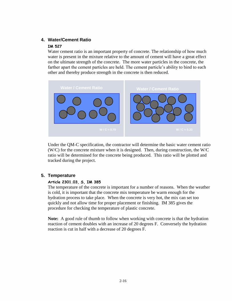
4. Water/Cement Ratio
IM 527
Water cement ratio is an important property of concrete. The relationship of how much
water is present in the mixture relative to the amount of cement will have a great effect
on the ultimate strength of the concrete. The more water particles in the concrete, the
farther apart the cement particles are held. The cement particle’s ability to bind to each
other and thereby produce strength in the concrete is then reduced.
Under the QM-C specification, the contractor will determine the basic water cement ratio
(W/C) for the concrete mixture when it is designed. Then, during construction, the W/C
ratio will be determined for the concrete being produced. This ratio will be plotted and
tracked during the project.
5. Temperature
Article 2301.03, S, IM 385
The temperature of the concrete is important for a number of reasons. When the weather
is cold, it is important that the concrete mix temperature be warm enough for the
hydration process to take place. When the concrete is very hot, the mix can set too
quickly and not allow time for proper placement or finishing. IM 385 gives the
procedure for checking the temperature of plastic concrete.
Note: A good rule of thumb to follow when working with concrete is that the hydration
reaction of cement doubles with an increase of 20 degrees F. Conversely the hydration
reaction is cut in half with a decrease of 20 degrees F.
Water / Cement Ratio
W / C = 0.70
Water / Cement Ratio
W / C = 0.33

2-17
Figure 2-19 Measuring temperature of fresh concrete
The following table shows the effect of the materials on the temperature of the
concrete.
Change in Temperatures of Individual Components of a Typical
Concrete Mix to Affect a 1o F Change in Concrete Temperature
Cement Water Aggregates
(coarse and fine)
9 o 4
o 1.6
o
6. Unit Weight
IM 340
When a mixture is designed, normally the unit weight is one of the properties that is
determined and becomes part of the parameters of the mixture. This information is then
helpful to those in the field. When concrete is measured in the field, the unit weight will
tell if the mixture produced is similar to the mix design.
Producers know exactly how much one cubic yard (or cubic meter) of each of their mixes
weighs. This is called the unit weight of concrete. Unit weight is simply the weight of
material that will fill one unit of volume. In the concrete industry, one unit of volume is
usually either a cubic yard or a cubic meter.

2-18
Therefore, if a producer knows the exact weight of the materials that were batched into a
truck, he can calculate exactly how much volume that concrete will fill when placed.
This is the “weight versus volume” or “unit weight” relationship.
The unit weight calculation is:
Unit Weight = Weight of Concrete / Volume of Concrete
Under the QM-C Specification, unit weight is checked periodically during the paving
operation. The contractor’s QC/QA Plan will detail the frequency with which these tests
will be conducted.
7. Workability
In concrete paving, workability is a characteristic of concrete that describes how well the
concrete can be moved, molded, and shaped to the proper dimensions. It is impossible to
describe this characteristic in words but it is variable between mixtures and can change
with time within a given mixture.
There is no specification regarding workability. It is a characteristic of the concrete and
is affected by water cement ratio, aggregate gradation, and characteristics of the
cementitious materials.
The inspector should watch how the concrete moves though the paver and discuss the
workability with the contractor and the mix designer. If difficulty in placement of the
concrete arises, a change may be needed by the contractor in order to make the concrete
more workable.
D. Concrete Mixes
Classes of Mix
IM 529
The Iowa Department of Transportation has used a system of standard concrete mixtures
for many years. There are many pavements in service around the state that were built
using a standard mix. The standard mixture designs are grouped by strength and are
called classes.
IM 529 lists the standard concrete mixes used by the Iowa department of Transportation.
They are divided into classes of concrete mixes that are based on nominal strengths.
Project plans will specify a class of concrete mixture to be used and the contractor is free
to choose any one from those listed in IM 529 for that class of concrete.

2-19
Commonly a Class C concrete is specified for paving on primary roads and many
secondary roads. Class A and Class B mixtures may be specified on secondary paving
projects.
Today a number of PCC paving projects are let under the QM-C specification. This
includes a provision for the contractor to develop the concrete mixture. On those
projects, the standard mixtures are only used in hand work or in the event that something
arises that is beyond the contractor’s control.

2-20

C
HA
PT
ER
3
SU
BG
RA
DE
& B
AS
ES


3-1
Chapter 3 Subgrade and Bases Sections 2107 and 2109 and Article 2301.03, B
When talking about pavement design in Iowa, the words base and subbase often are used to
represent the lift of a selected material placed immediately beneath a pavement. The earth grade
at the bottom of the pavement structure, whether modified by special treatment or not, is referred
to as the subgrade.
All of these bases, regardless of placement methods, can be built to acceptable tolerances and
provide the working platform necessary to:
Enhance the performance of the finished product
Minimize the loss of concrete
Eliminate short core penalties
Contribute to value added payment such as smoothness
A. Subgrade Treatment (Stabilization)
While the bulk of general embankment fill consists of regular Class 10 soil, the upper
material in the subgrade directly beneath the pavement structure (subbase, base, and
pavement) is built of higher quality material. This higher quality material is referred to as
“subgrade treatment”. A subgrade treatment layer can be composed of higher quality
materials that are imported on to the project or it can be created by improving the material
that is already in place. The process of improving the material that is in place is often called
'stabilization'.
When necessary, subgrade treatment is used to provide uniform and better support for the
subbase, base, and pavement. The type of subgrade treatment used depends on the type, the
quality, and quantity of natural soils available on the project. The subgrade treatment
material is much stronger than the regular Class 10. However, subgrade treatment should not
be used to cover up unstable locations. Thus, it is critical to make sure that the lower Class
10 foundation soil is in reasonable condition before the subgrade treatment is placed, because
it may not be economical to later remove the treatment material for repair of the lower
foundation.
When available, designers will always recommend using on-site soils or borrow for the
subgrade treatment. This is simply an economic decision since on site materials are typically
on the order of five to ten times cheaper than other subgrade treatment options.
Following are some of the typical materials used as subgrade treatment:
1. Select Soil
Section 2102
The normal materials for select subgrade treatment are clay loam, loam, or sand. These
materials are either granular (predominantly sand) or cohesive (a loam or clay loam

3-2
which is a good mixture of sand, silt, and clay). Because of the composition and
gradation, the density and shear strength are much higher when they are properly
compacted.
Figure 3-1 Select sand
At locations where modifications were done but stability is questionable, additional select
should be considered. This is an economical way to improve stability.
If select sand is used for subgrade treatment, it is often specified in project plans that 3
inches of special backfill be incorporated into the surface. This increases strength and
cohesion under construction traffic.
2. Special Backfill
Sections 2102 and 4132
Special backfill is a uniform mixture of coarse and fine particles of crushed concrete,
crushed limestone, composite pavement, or a mixture of gravel, sand, soil; or a mixture of
crushed limestone, gravel, sand, and soil. In other words, the special backfill could be a
variety of different materials. The requirement for this material is that it has to meet a
certain gradation. Since the materials vary, different behaviors should be expected. For
example, a piece of rounded gravel is going to provide much less stability than a piece of
crushed limeston. Special backfill has a relatively high content of fine particles which
makes it a very stable material. On the other hand, it also makes it a non-drainable
material. Because special backfill is typically a very stable material, it is often used to
stabilize areas where a subgrade is soft and unstable.
3. Polymer Grid
Section 2113

3-3
Polymer grid is a high strength polymer material, which is called 'Subgrade Stabilization
Material' in Iowa DOT specifications. It is often used in combination with special
backfill as an alternative to select backfill. When on-site materials are not of sufficient
quality to use in the upper part of the subgrade, polymer grid will then likely be used with
special backfill material placed above it.
The open grid structure of polymer grid works best with aggregate base for the
interlocking effect. A polymer grid is used by Soils Design for subgrade strength. Grids
work because the material has a very high tensile strength which allows wheel loads to be
spread over a much larger area rather than having localized punching failure, ruts, etc.
Figure 3-2 Polymer grid used as subgrade treatment
Polymer grid is also used to provide additional support at unstable locations of Class 10
foundation soils below the subgrade treatment. A polymer grid should be utilized when
other methods have been tried but were not successful. Do not attempt to fix the polymer
grid if the stability is not enough. The best thing to do is to add more special backfill on
top.
A polymer grid should not be extended beyond the edge of the pavement; otherwise it
will interfere with the longitudinal subdrain installation.
4. Fly Ash Stabilization
Fly ash has been used to stabilize wet or unstable foundation soils beneath the subgrade
treatment. In some cases it has been used to stabilize a subgrade treatment of low quality.
Type C fly ash is self-cementing when hydrated, and can be mixed with soil to form a
low-grade 'concrete' using soil as aggregate. Fly ash requires moisture for hydration, so
addition of fly ash also removes water from wet unstable soils.

3-4
A typical mix ratio is 10 to 15% fly ash by dry weight of soil. Water may be added if
needed. The mixture must be well pulverized and compacted near optimum moisture.
Since setting begins soon after hydration, compaction is done soon after mixing to
prevent breakdown of the curing soil-fly ash mixture by compaction equipment.
Figure 3-3 Spreading fly ash
Figure 3-4 Adding water to fly ash
Figure 3-5 Mixing fly ash with soil
Figure 3-6 Compacting fly ash treated material
B. Base and Subbase
Sections 2109, 2111, 2115, 4121, 4123, & 4132
Most agencies specify trimming of the subgrade with electronically controlled trimmers to a
specified tolerance prior to any subbase or base construction. The subbase (if specified) and
base are then placed to uniform specified depths.
The subgrade is 'proof' rolled no more than one week prior to trimming. Proof rolling is very
critical to make sure that the subgrade is strong enough to support the pavement structure.
Soft or unstable areas must be reworked to obtain adequate stability. Refer to Section 2109.
After being rolled, the subgrade surface shall be at the required elevation.
3-5
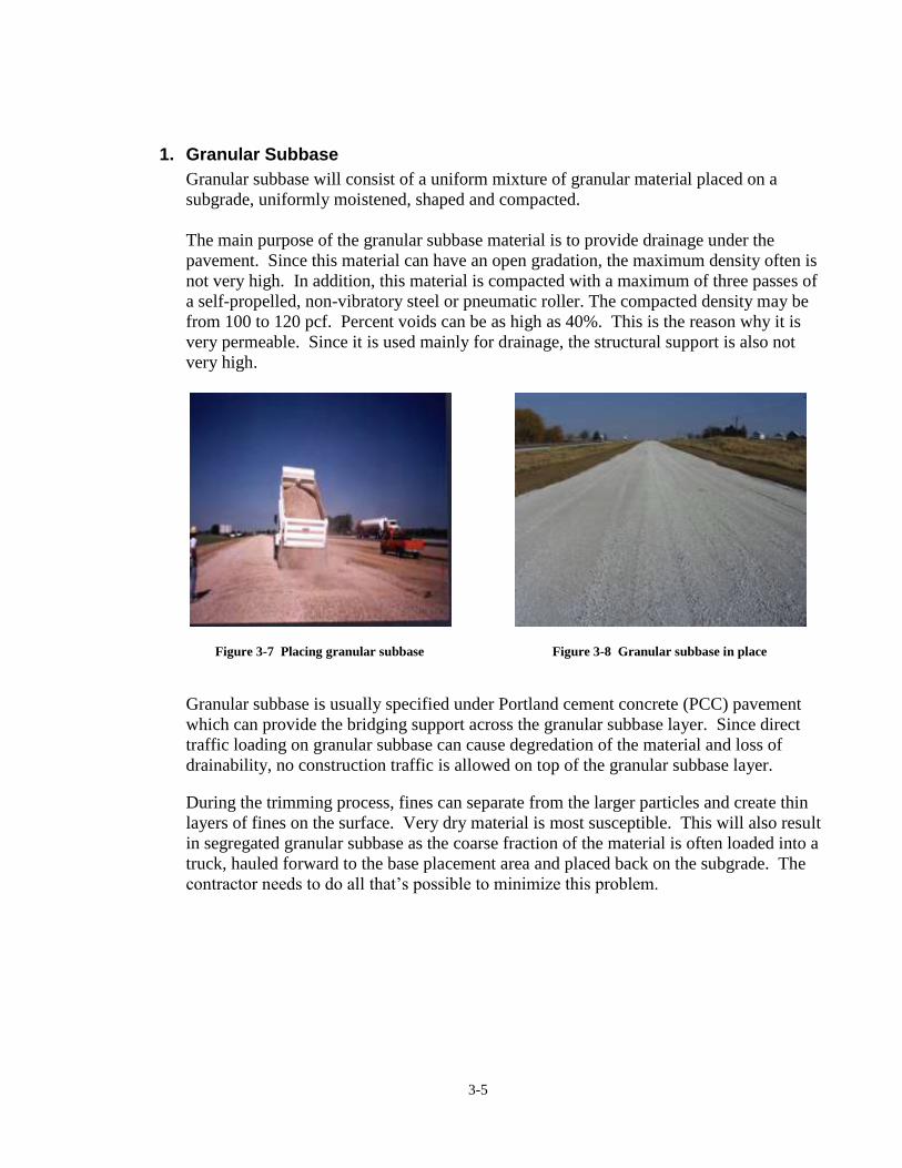
1. Granular Subbase
Granular subbase will consist of a uniform mixture of granular material placed on a
subgrade, uniformly moistened, shaped and compacted.
The main purpose of the granular subbase material is to provide drainage under the
pavement. Since this material can have an open gradation, the maximum density often is
not very high. In addition, this material is compacted with a maximum of three passes of
a self-propelled, non-vibratory steel or pneumatic roller. The compacted density may be
from 100 to 120 pcf. Percent voids can be as high as 40%. This is the reason why it is
very permeable. Since it is used mainly for drainage, the structural support is also not
very high.
Figure 3-7 Placing granular subbase
Figure 3-8 Granular subbase in place
Granular subbase is usually specified under Portland cement concrete (PCC) pavement
which can provide the bridging support across the granular subbase layer. Since direct
traffic loading on granular subbase can cause degredation of the material and loss of
drainability, no construction traffic is allowed on top of the granular subbase layer.
During the trimming process, fines can separate from the larger particles and create thin
layers of fines on the surface. Very dry material is most susceptible. This will also result
in segregated granular subbase as the coarse fraction of the material is often loaded into a
truck, hauled forward to the base placement area and placed back on the subgrade. The
contractor needs to do all that’s possible to minimize this problem.

3-6
Figure 3-9 Variablity of granular subbase due to
segregation during trimming
Figure 3-10 Fine material on the surface due to segregation
One quick and easy way to check permeability is to fill a one-gallon milk jug with water.
Pour this gallon of water from waist level down at one spot. If the water drains away,
and there is no sign of any buildup after 30 seconds, the granular subbase layer is
considered permeable.
2. Modified Subbase
Special backfill composed of sand and gravel, which is allowed in Section 4132 of Iowa
DOT Standard Specifications, may not provide the strength needed to support
construction traffic or equipment. A greater percentage of crushed particles and a denser
gradation are needed for stability.
Figure 3-11 Modified subbase

3-7
Modified subbase is specified in Section 4123 in order to designate a material which will
provide stronger support, especially for paving equipment for full-depth asphalt. The
specification places a limit of 50% sand and uncrushed gravel content in the mix, as well
as includes other specific gradation requirements.
The specification also adds a requirement that the subgrade be proof rolled by a legal axle
load before placing the subbase.
3. Special Backfill
Special backfill is used mainly for stability/support. It is normally specified under
asphalt cement concrete (ACC) pavement. Type A compaction is required for special
backfill. Also, since special backfill is paid by the ton, the contractor usually uses a
vibratory steel roller for compaction. This makes the special backfill very strong.
Construction traffic is allowed to run on special backfill. This is one of the reasons why
special backfill is specified under ACC pavement so that the asphalt material can be
delivered to the paver.
Special backfill is also used under PCC pavement when availability of select backfill is
limited, such as in urban reconstruction projects.
Many times the question about drainability of the special backfill is asked. The answer is
its permeability can vary because of the differing materials and gradation range allowed
for special backfill by specification. It is generally less permeable than granular subbase,
but more permeable than most Class 10 or select soil materials, except sand. As a general
rule, it is considered permeable enough to require installation of continuous longitudinal
subdrains when it is used.
Because requirements for granular subbase, modified subbase, and special backfill
overlap, materials can be produced that meet the requirements for more than one base
material.
Figure 3-12 Material used as both special backfill and granular subbase

3-8

CH
AP
TE
R 4
DE
SIG
N


4-1
Chapter 4 Design
In order to understand what is required to construct a project, an understanding of what
information is specified on the plan and within the contract documents is essential. This chapter
will present some of the important pieces of information that are contained on the project plans
and road standards that will be necessary in order to define what work is to be accomplished.
A. Project Plans
Project plans prepared by the Iowa Department of Transportation or by private consultants
are arranged with a specified format. The following sections contain information that will be
important when building a pavement project.
1. Title Sheet, Location Map, & Legend - A Sheets
These sheets provide information on the project location and length, vehicle counts, index
of sheets, and beginning/ending stations of the project and divisions within the project.
2. Typical Cross Sections- B Sheets
These sheets provide dimensions and other information with cross section views. These
views are typical for the locations listed in tabs. There can be several different typicals
with each set of plans, which make the location information important to help decide
which typical is used where. In a set of plans the typical sections include mainline
pavement, superelevations, curbs, ramp grading and paving, and shoulder details. Also,
it’s important to look for any references to other plan sheets for special details.
3. Estimate of Quantities and General Information- C Sheets
These sheets give you the design quantities and additional information for the project.
Many bid items have reference notes which further define the item. These are where the
class of concrete, thickness of the pavement, and often the required durability class of the
aggregate are given. Also included are general notes for the project and storm water
pollution prevention requirements. A very important piece of information that is found
here is the list of the applicable Road Standards.
4. Mainline Plan and Profile Sheets- D Sheets
These sheets give a plan and profile view of the entire project. They usually begin with
the lowest station number and go to the highest station number. Note that profile
elevations for top of slab at any given station are provided on these sheets. New and
existing drainage features, entrances, and ditch cut information are also shown.
5. Side Road Plan and Profile Sheets- E Sheets
These show basically the same information for side roads as listed above for mainline.

4-2
6. Interchange Geometrics- K Sheets
These sheets show interchange staking, jointing, and edge profile information as well as
centerlines and base lines in relationship to each other. Jointing at ramp intersections are
also shown.
7. Intersection Geometrics- L Sheets
These sheets show intersection staking, jointing, and edge profile information along with
pavement jointing details at side road intersections.
There is much more information included in a plan set beyond that shown above. The above
information is just a selection of the most important information for PCC paving.
B. Joints
Articles 2301.03, N, O, and P Section 4151
Road Standard PV-101
As cement hydrates, water is chemically combined with compounds in the cement particles.
As this process continues, the space taken up by the water closes as the water leaves. This
causes the concrete to shrink. When concrete is placed in large amounts, as in pavement, the
volume change causes stresses. These stresses eventually will be greater than the tensile
strength in the concrete and a crack in the concrete results. A joint is simply a designed
crack.
A sawed joint provides a plane of weakness to allow the pavement to crack at designated
locations. Controlled cracks are much easier to maintain than random cracks. By designing
the pavement with joints, the natural cracks can occur without affecting the ridability and
performance of the concrete pavement.
Figure 4-1 - Joint sawed at top of pavement and crack below

4-3
Section 4151 specifies the steel that is used in some joints. All bars used in pavement, either
smooth dowels or deformed tie bars, are specified to have an epoxy coating. This helps to
prevent the bars from corroding.
1. Joint Types
Many types of joints are used in a concrete paving project. The plans will specify where
each type of joint will be used. The following is a discussion of the types of joints, the
Road Standards where they are specified, and the types of saw cuts that are used to create
the joint in the finished pavement.
a. Transverse Contraction Joints
PV-101
Transverse contraction joints are constructed laterally from centerline and spaced to
control cracking from stresses caused by shrinkage, moisture, and thermal changes.
Joints may either be oriented at right angles to the centerline or skewed to the
centerline.
Pavements that carry a significant amount of truck traffic will have dowel bars placed
in the joint in order to transfer the load as truck tires cross the joint from one slab to
the next. This prevents vertical movement of the slabs and pumping of the subgrade
material.
Most primary pavements will have dowel bars at the joints. Often secondary roads
and city streets do not.
As the pavement expands and contracts with change in temperature, the joints open
and close. The dowels are smooth bars to allow for movement. They are coated with
an asphalt or wax material to prevent bonding with the concrete.

4-4
Figure 4-2 Transverse Contraction Joint
b. Day’s Work and Header Joints
PV-101
Joints installed at the end of the daily paving operation are called Days Work Joints.
Transverse construction joints are also placed when there is a significant delay with
concrete delivery to the site or other gaps in continuous paving operations and are
called headers. These are installed at a location between planned contraction joints
and utilize deformed bars.
Figure 4-3 Days work or header joint

4-5
c. Longitudinal Contraction Joints
PV-101
These are tied joints that are constructed between lanes or other pavement adjacent to
a lane. They are intended to prevent adjacent lanes from separating.
The sawing of these joints may be delayed until after the sawing is completed for the
contraction joints. An early entry saw may be allowed for sawing these joints
provided the correct depth and width of joint can be achieved. Deformed tie bars are
used in these joints because their purpose is to prevent movement.
Figure 4-4 Longitudinal Contraction Joint
d. Expansion Joints
PV-101
While it may not be readily apparent when standing on the side of a roadway,
pavements move due to expansion and contraction caused by temperature and
moisture differences. Some bridges also move, but don’t necessarily move in the
same manner as the adjacent pavement. Because bridges are scattered between
sections of pavement, and both move independently of each other, something needs to
be done to prevent the differences in movement from damaging the pavement and the
bridge. For this reason, expansion joints are constructed on either end of the bridge.
These are wide, often 3 or more inches, and typically close over a number of years.
These isolation joints as they are often called help absorb the differential movement
of the pavement and bridge to prevent damage.

4-6
Expansion joints may also be specified at railroad crossings. In the past, they have
been used at regular intervals in pavements to provide relief and prevent blowups.
This practice is usually discouraged because of the faulting of the contraction joints
that often develops as the aggregate interlock in non-doweled pavements is lost.
Normally, these joints will have dowels to provide load transfer. They are filled with
a filler material to keep out rocks and dirt that might resist their closing up, which
they are designed to do.
Figure 4-5 Expansion joint
2. Saw cuts
The Iowa Department of Transportation requires joints to be sawed with one pass. The
alternative procedure is to make an initial narrow, deep cut and then come back and make
a widening reservoir cut later. The two cut procedure has not been a part of the Iowa
specifications for a number of years, but it is still in use in many other states.
Timing of the saw cut is critical. To begin sawing when the concrete is too green will
result in raveling of the joint. If the sawing operation is delayed too long, random cracks

4-7
will form. There is a window of time between the two extremes when the sawing
operation must take place. It is the contractor’s responsibility to determine the proper
time to saw the pavement. The specifications require that cracks be prevented, but the
inspector can only advise the contractor to watch the set of the concrete in order to
accomplish the sawing within the necessary time.
The depth of the saw cut at the joint is determined by the category of saw used and
thereby the timing of the saw cut. Road Standard PV-101 gives the specific requirements
for each of these two joint types, as determined by the type of saw used.
There are two categories of saws that can be used for sawing.
a. Conventional Saws
The conventional saw is a large powerful saw that begins the sawing operation once
the concrete has obtained enough strength to support the weight of the saw. It must
complete the sawing operation before the concrete begins to contract and build up
tension within the concrete to the point of cracking.
The conventional saws are of two types, wet saws or dry saws. Wet sawing uses
diamond blades and requires a stream of water to cool the blade. Dry sawing uses
abrasive or diamond blades and does not use water during the sawing operation.
Figure 4-6 Dry saw
Figure 4-7 Wet saw
b. Early Entry Saws
The other category of saws are early entry saws. The age of the concrete when early
entry sawing begins is much sooner than with the conventional saws. The window
for sawing the concrete is also smaller with this type of saw. If the concrete starts to
contract and develop stresses, it is too late to saw the slab with a early entry saw. The
early entry saw is used to cut a shallow cut (about 1 1/4 inch deep) instead of the
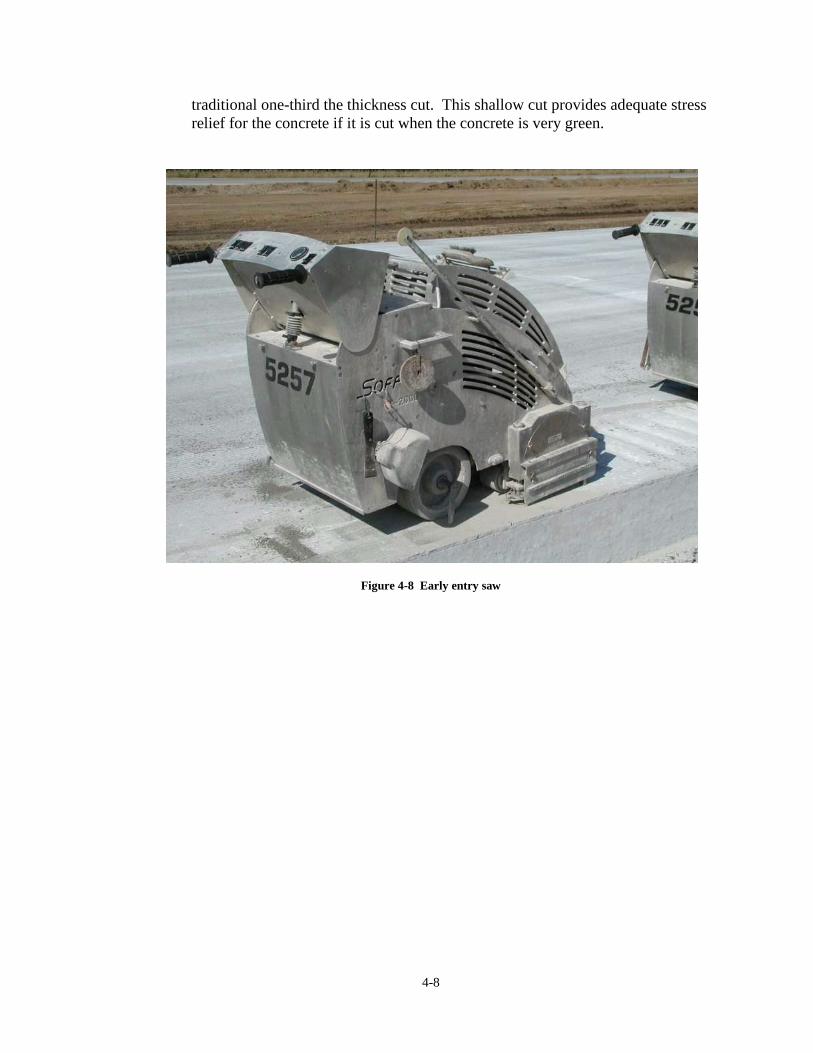
4-8
traditional one-third the thickness cut. This shallow cut provides adequate stress
relief for the concrete if it is cut when the concrete is very green.
Figure 4-8 Early entry saw

C
HA
PT
ER
5
EQ
UIP
ME
NT


5-1
Chapter 5 Equipment
A. Trimmer and Roller
Section 2001 and 2109
A variety of equipment is used to prepare subgrade and place base prior to the placement of
concrete.
In some cases, the subgrade may need to be ripped and re-compacted in order to create a
uniform platform on which to place the base material. When this is done, normally a motor
patrol is used to accomplish this work.
Figure 5-1 Ripping the grade prior to subgrade trimming
The first step after the stringline has been placed and checked, is to trim the subgrade to the
correct profile and cross section. A trimmer is typically used to trim the subgrade, but motor
patrols have also been used. Trimmers are equipped with controls that run off from the
stringline to adjust both the elevation and alignment of the machine.

5-2
Figure 5-2 Trimming subgrade
If the subgrade or subbase needs water for proper compaction, a distributor mounted on a
truck or trailer equipped with pneumatic tires will be used for applying water to the roadway.
The distributor shall be equipped with an adequate pressure pump and flush or spray bars to
distribute water evenly over the intended area.
Once the subbase is placed on the grade, a motor patrol, small self-loading scraper, or small
bulldozer is used to level the aggregate subbase material and bring it to the rough grade.
Figure 5-3 Small dozer used to level subbase material
The trimmer will again be used to trim the top of the subbase to the elevation of the bottom
of the pavement. A roller is then used to consolidate the subbase material.

5-3
Figure 5-4 Trimming subbase material
Figure 5-5 Roller used to compact subgrade and subbase
B. Transporting Vehicles
Section 2001, Article 2301.02, B
There are primarily three types of vehicles that are used to transport concrete to the project
site: dump trucks, agitator trucks, and transit mixers, better known as ready mix trucks.

5-4
1. Dump Trucks
Dump trucks are the most commonly used vehicle to transport concrete from the batch
plant to the paving site.
Advantages:
Versatile. They can be used for hauling other material when not used for
transporting concrete, such as rock for base and shouldering.
Quick loading and unloading.
Disadvantages:
Limited haul time, 30 minutes by Iowa DOT Specifications, between batching
and placement. This limitation is imposed because no mixing or agitation is
performed within the transit vehicle.
Limited flexibility during discharge. Discharging a portion of a load at a time or
placing it anywhere other than at the end of the dump box is difficult.
Construction headers or irregular shapes normally utilize one of the other two
delivery vehicle types.
Overhead clearance necessary to discharge.
Figure 5-6 Dump truck
Although not commonly used in Iowa, concrete can be delivered in semi trailer trucks.
These will carry two batches of concrete and thereby reduce the number of trucks needed.
Some modification of dumping procedures may be needed due to the large amount of
concrete in a single load.
These may include either the dump box type or flow boy trailer. The dump box type has
the problem of overfilling the hopper when discharging at the belt placer. Flow boy
trailers work very well since uniform, contiuous flow of concrete is discharged into the
hopper.

5-5
Figure 5-7 Semi trailer delivery truck with dump box
Figure 5-8 Semi trailer delivery truck with flo boy box
2. Agitator Trucks
The agitator truck is commonly used in paving operations. These are called agitator truck
because they have paddles inside the truck box. These paddles continually turn the
concrete while the truck is in transit.

5-6
The turning of the concrete is the reason the haul time is extended. If the paddles are not
rotating, the truck is no different than a dump truck and haul time would be only 30
minutes.
Advantages:
Extended haul time, 90 minutes by Iowa DOT Specifications.
Ability to direct discharge for
hand pours.
Disadvantages:
Reduction in ease and speed of both loading and unloading.
Limited in usage, to concrete delivery.
Overhead clearance necessary to discharge.
Figure 5-9 Agitator truck
Figure 5-10 Paddles inside agitator box
Often a small number of agitators are used in a paving operation along with a majority of
dump trucks. This gives the contractor the ability to take advantage of the extended haul
time during hand operation at the beginning and end of the day and during breakdowns.
3. Ready Mix Trucks
Ready mix trucks can be used as delivery vehicles when they are charged from a central
batch plant or they can be used to mix the concrete. These vehicles are normally used in
lower volume paving, such as urban paving. When they are used for higher volume
production, they are usually used as delivery vehicles with the mixing done at the central
batch plant.
Advantages:

5-7
Extended haul time, 90 minutes by Iowa DOT Specifications.
Ability to add water or air entrainment at the project site.
No overhead clearance restrictions.
Disadvantages:
Reduction in ease and speed of both charging and discharging.
Limited in usage, to concrete delivery
Figure 5-11 Ready mix truck
C. Placing and Consolidating
Article 2301.03, F
There are two pieces of equipment that move the concrete from the point of discharge of the
truck, place it on the grade and construct it into a finished pavement.
The belt placer is the first piece. Not all paving operations will utilize this piece of
equipment, but when used, it performs a number of functions.
If the concrete can be hauled on the grade ahead of the paving operation and dumped directly
in front of the paver, a belt placer is normally not used.
The paver is the other piece of equipment. It is the heart of the paving operation.
1. Belt Placer
A belt placer conveys the concrete from the truck to the front of the paver. It is used
when it is not permissible to back trucks down the finished grade, and dump directly on
the grade in front of the paver. The belt placer allows the truck to unload from the side of
the roadbed. The belts then deposit the concrete in the middle of the paving area just in

5-8
front of the paver. Like the trimmer, it utilizes the stringline for horizontal and vertical
control.
A belt placer is normally not used when ready mix trucks deliver the concrete. The
shoots attached to the drums allow the concrete to be placed out on the grade, even with
side delivery. Belt placers are not commonly used for county and city paving. These
pavements often are not placed on granular base and do not contain dowels. Therefore
trucks can back on the grade and unload ahead of the paver.
The belt placer performs the additional function of spreading the concrete uniformly
across the width of the pavement. This provides a more uniform flow of concrete into the
paver, which can result in a smoother pavement.
Figure 5-12 Belt placer
Figure 5-13 Concrete spread on grade by belt placer

5-9
Figure 5-14 Dumping concrete on grade without belt placer
2. Iowa Special
The Iowa Special is a piece of equipment that was developed in Iowa and often used for
county paving. It is a special conveyor attached to a trimmer and used to convey
concrete from in front of the trimmer to behind the trimmer. This allows trucks to back
down the grade to the trimmer but still have the trimmer bring the grade to a true shape
and elevation right ahead of the paver. This equipment is used when there is limited
shoulder width for a haul road.
Figure 5-15 Iowa Special

5-10
Figure 5-16 Iowa Special - Front Figure 5-17 Iowa Special – Back
3. Paver
The paver, or more formally known as the finishing machine, is the heart of the paving
operation. It forms the concrete into the pavement, with proper width and at the proper
elevation and thickness. It consolidates the concrete through vibration. Centerline tie
bars and sometimes dowel bars are inserted into the fresh concrete as a part of the paver’s
function.
The paver has three main parts. The augers move the concrete pile one way or the other
in order to maintain a fairly uniform head of concrete in front of the paver. This helps
insure that one area does not run out of concrete and prevents a big pile in one area,
which may make the paver ride up over it and thereby create a bump.
Figure 5-18 Front of paver

5-11
Next comes the vibrators. They consolidate the concrete. Proper setting of the frequency
of each vibrator is important. Over vibration can damage the air entraining system and
segregate the aggregate within the concrete. Under vibration can result in voids within the
concrete and reduce both strength and durability.
Figure 5-19 Augers and vibrators
The last major component of the paver is the pan. It strikes off the concrete to the proper
elevation and smoothes the surface. There are a number of adjustment devices attached
to the pan in order to be able to make changes to the crown of the pavement, particularly
as superelevations are encountered. Some contractors attach finishing equipment, such as
a V float to the paver as the first step in the finishing process and specifically to help
create a smooth ride.
Figure 5-20 Vibrators and pan

5-12
D. Finishing
Article 2301.03, H
Finishing tools are used on the surface of the pavement immediately after it comes out from
under the pan of the paver. Finishing closes the surface and removes bumps and
irregularities.
The common types of finishing devices that are attached to the paver are the V float and the
oscillating screed. Not all contractors use these but some feel they aid in obtaining a smooth
ride.
Figure 5-21 V float
The oscillating screed brings some mortar to the surface. If it is not excessive, it is not a
problem and simply aids in closing the surface. If excessive slurry is evident, either too
much water is being applied to the burlap or water needs to be taken out of the mix.
The V float is suspended behind the paver and floats the entire surface as it passes. The
oscillating screed works back and forth across the slab while it oscillates on a short forward
to backward stroke.

5-13
Figure 5-22 Oscillating screed float
Hand finishing tools include floats, and straight edges. Iowa specifications require the
pavement surface be checked with a ten-foot straight edge. The final finish is usually
accomplished with a bull float.
Figure 5-23 Hand finishing tools

5-14
Figure 5-24 Straightedge and hand float
E. Texturing
Article 2301.03, H
Texturing consist of two types: micro texture and macro texture. Both are accomplished in
the paving operation but normally done with two separate pieces of equipment.
1. Micro texture
Micro texture is the roughened surface created by the dragging of astro turf along the
fresh concrete surface. Often a bridge simply is attached and is pulled along, using
attached cables, behind the paver. Pushing this bridge along by hand is discouraged. The
results in the bridge “crabbing” along and leaves a wavy texture pattern.
Such a pattern, although not addressed in the specifications, is very noticeable to the
driver and conveys a message of poor workmanship.
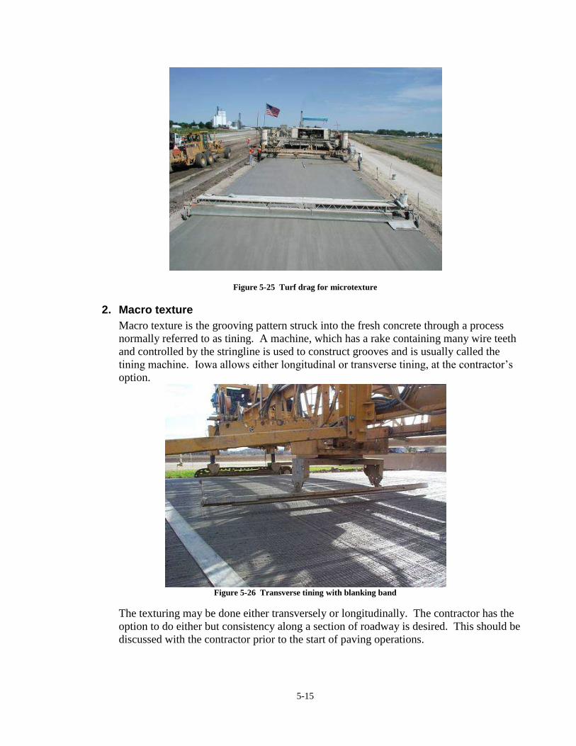
5-15
Figure 5-25 Turf drag for microtexture
2. Macro texture
Macro texture is the grooving pattern struck into the fresh concrete through a process
normally referred to as tining. A machine, which has a rake containing many wire teeth
and controlled by the stringline is used to construct grooves and is usually called the
tining machine. Iowa allows either longitudinal or transverse tining, at the contractor’s
option.
Figure 5-26 Transverse tining with blanking band
The texturing may be done either transversely or longitudinally. The contractor has the
option to do either but consistency along a section of roadway is desired. This should be
discussed with the contractor prior to the start of paving operations.

5-16
Figure 5-27 Longitudinal tining
The Contractor is encouraged to construct the grooves as shallow as practical within the
Specification limits. Shallow texture reduces pavement noise but still provides adequate
friction.
Figure 5-28 Longitudinally tined surface
F. Curing
Article 2301.03, K

5-17
Curing is a critical final step in the paving operation. This is completed with a machine
commonly known as a cure cart. It has a holding tank to hold the curing compound and a
spray bar with nozzles to apply the cure to the surface of the pavement, including the edges,
in a uniform application.
Figure 5-29 Cure/texture cart
Sometimes the curing operation and the tining operation are combined on one machine. This
has advantage for the contractor by minimizing the amount of equipment needed but has the
drawback of interfering with one operation if a malfunction occurs with the other operation.
Figure 5-30 Spray bar on cure cart

5-18
G. Sawing
Article 2301.03, N
Saws are used to cut the joints in concrete pavements. They are commonly grouped into two
categories: early entry saws and conventional saws. Span saws are also used, but are rarely
used in Iowa.
1. Early entry saws
Early entry saws may be used, at the contractor’s option, to cut the transverse joints.
They make a shallow cut, a little more than an inch deep. Sawing must begin very soon
after the concrete is placed, often within about three to four hours. The saws used by
many contractors in Iowa use an up-cut design. This produces a clean joint with very
little dust.
Figure 5-31 Early entry saw
Figure 5-32 Conventional dry saw
2. Conventional Saws
Conventional saws are much heavier and more powerful than early entry saws. The
contractor must wait to begin sawing until the concrete has gained more strength than the
point at which sawing can begin with early entry saws. The saw depth is the major
difference in the approach to sawing. Conventional saws make a cut that is normally
one-third the thickness of the slab. Often the sawing is done at night.
Conventional saws can be of two types: dry saws and wet saws. Wet saws use water to
cool the saw blade during the sawing operation. These saws use diamond blades. Dry
sawing does not require water and utilizes either diamond or carborundum blades. A
disadvantage of dry sawing is the dust that is created, which can especially be a problem
in urban areas or when wind carries the dust across open lanes of traffic.

5-19
3. Span Saws
Span saws are heavy duty saws used for high production on large projects. They are
capable of spanning the full with of a pavement and sawing joints much more quickly
than conventional saws. They are very similar to conventional saws in that the contractor
must wait to begin sawing until the concrete has gained sufficient strength to allow the
weight of the equipment without damaging the slab.
Figure 5-33 Wet conventional saw
Figure 5-34 Span saw
H. Sealing
Article 2301.03, P
The joint sealing operation will follow the joint sawing and includes a number of steps. The
type of joint being sealed and the type of saw that was used will determine what operation
will be required.
The joint must be cleaned. A high-pressure water blast must be used if the joints were sawn
with a wet saw. An air blast must be used to clean the joint if a dry saw was used. A
conventional air compressor is commonly used for this work.

5-20
Figure 5-35 Air blast prior to sealing
Figure 5-36 Water blast prior to sealing
Depending on the joint design, a backer rod may be required. A suitable tool must be used
which will insert the rod to the proper depth.
Hot pour sealers are installed using equipment that has a kettle that is thermostatically
controlled. It is very important to keep the temperature within the temperature limits set
forth by the manufacturer. If the temperature is exceeded, bubbles can form on the surface of
the in place sealant. These bubbles eventually can pop and create a hole in the joint seal,
which allows water to enter the joint.
Figure 5-37 Backer rod installation
Figure 5-38 Sealing with hot pour sealant

C
HA
PT
ER
6
PR
IOR
TO
PA
VIN
G


6-1
Chapter 6 Prior to Paving
Before the contractor can begin paving, a number of activities must occur. This chapter
describes those activities that are a part of the paving process but are performed before
commencement of the paving operation itself.
A. Control
Section 2526
In order to construct a pavement to a set profile, reference points must be established. A
construction survey crew will begin the process by setting paving hubs at certain intervals
and establishing elevation references on those stakes.
Figure 6-1 Setting paving hubs
Figure 6-2 Paving hub with survey information on flat or
"pie" stake
The next step is for the contractor to erect a stringline supported by stakes. This is set at a
certain distance above the grade line at an offset, and normally above the construction stake.
It will be used as guidance for all the equipment that will be trimming grade, trimming base,
placing and shaping the concrete, and constructing texture. These machines are set up to use
the string line as control for alignment and elevation. There will normally be a string line for
each side of the pavement. The contractor will set this string line at a vertical offset to the
edge of slab using the grades marked for these hubs.
Before the contractor begins paving, it is necessary for the PCC grade inspector to do a
number of checks utilizing the paving hubs and these lines. Normally these stringlines will
be level with each other on a tangent section of roadway. However, sometimes the stringline
on the haul road side is placed lower to facilitate the use of a belt placer. In a transition to a
curve, one stringline will be raised as the roadway transitions into the curve and the other
will remain the same or is lowered.

6-2
Figure 6-3 Setting the stringline
1. Survey Stakes
It is necessary for the inspector, surveyors, and grading contractor to get together before
the paving hubs are set to discuss how the grades will be derived. There are basically two
ways to grade the paving hubs, off a level line or off a projected line. A level line grade
would be as if you were to place a level on the edge of slab and measure over the offset
distance to the hub, the distance between the level and the hub will be the grade for that
hub.
When the grade is a cut, the level line would actually be lower than the top of the hub.
This would happen when the top of the paving hub is set higher than the edge of slab.
The surveyors will subtract the edge of slab elevation from the hub elevation to calculate
the cut grade.
When the grade is a fill, the level line would be higher than the top of the hub. This
would happen when the top of the paving hub is set lower than the edge of slab. The
surveyors will subtract the hub elevation from the edge of slab elevation to calculate the
fill grade.
A projected line grade is the grade at the edge of slab projected out to the paving hub. It
is the distance of the offset times the % of cross slope. It can be thought of as the slope
along the top of the pavement projected on out to the hub. The surveyors will multiply
the offset to the paving hub by the % cross slope and add it to the edge of slab grade.
They will then take this projected grade and the hub elevation to calculate the grade for
that paving hub as they do with a level line grade. Although both methods are acceptable
and widely used, the use of both methods on the same project is discouraged. This could
lead to confusion and costly errors.

6-3
Figure 6-4 Front of the flat
Figure 6-5 Back of the flat
A common practice to help mark the transition points for superelevations and horizontal
curves is to paint a transition hub stake with orange or some other color paint in order to
alert the paving crew of the transition.
Figure 6-6 Stake showing trasition to superelevation
2. Stringline
The stringline may be wire, cable, woven nylon, polyethylene rope, or other similar
material. The stringline stake should be long enough to be rigid when driven into the
subgrade. There must be an adequate stake length exposed above grade to allow
adjustment of the stringline to the desired height above the subgrade profile.

6-4
The stringline stake is placed in a vertical position outside the hub line. When the line is
inserted into the holder arm slot it can be adjusted to a point directly over the hub tack
point.
Figure 6-7 Setting the stringline
Figure 6-8 Stringline above the survey stakes
The stringline supports are required to be located at 50-foot (15-meter) intervals unless
horizontal or vertical curves are encountered. In those cases the stringline supports are
required to be placed at 25-foot (8-meter) intervals.
Many contractors prefer to run a stringline on each side of the paver. They feel that a
smoother ride can be obtained with this dual stringline system.
The staking system normally includes hand winches placed at appropriate intervals
(usually not more than 1000 feet (300 meters)) to tighten the line to the extent necessary
to avoid any perceptible sagging between stakes. Use caution when tensioning the
stringline. A sudden break in the stringline could cause severe injuries.
Some agencies increase the visibility of stringline by placing ribbons on them.
The machine elevation sensing wand rides beneath the string, and the alignment-sensing
wand rides against the inside of the string. Neither of these wands should deflect the line
a measurable amount.
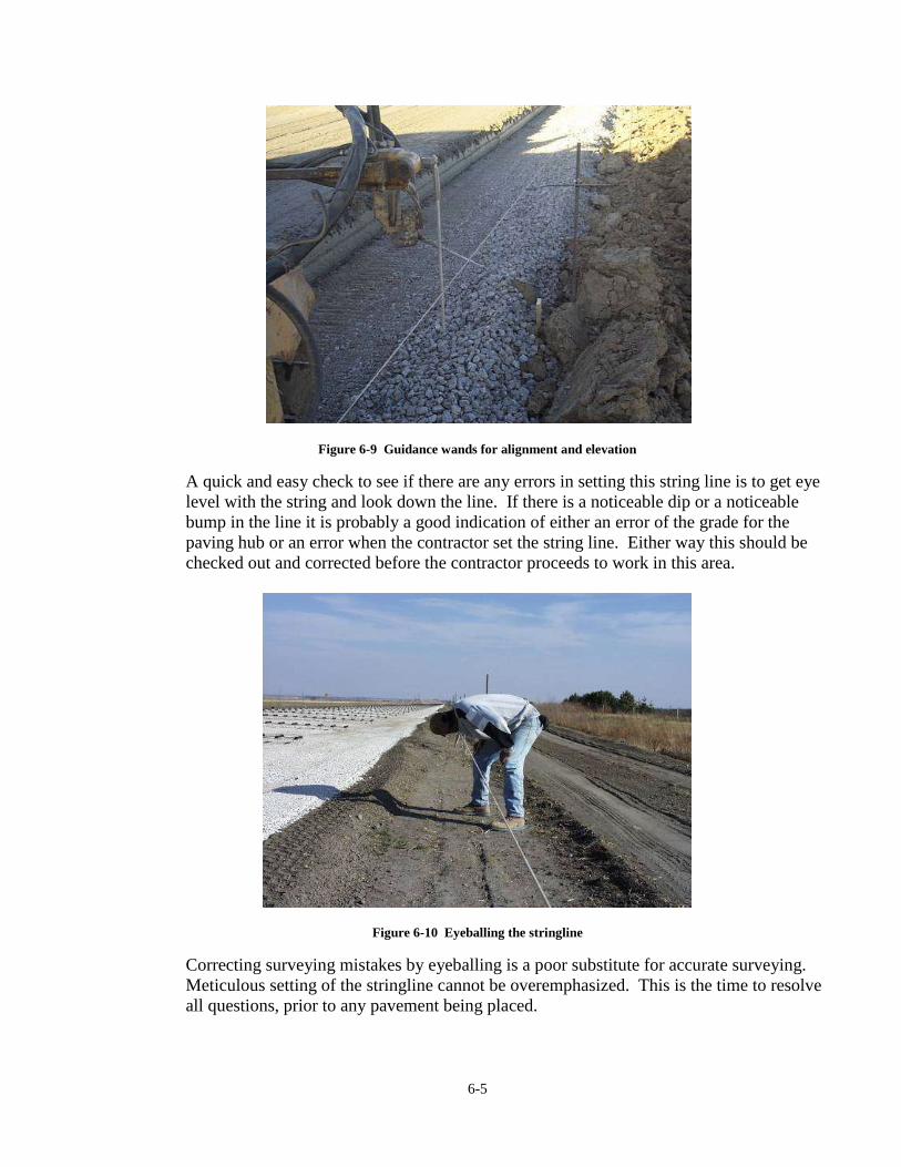
6-5
Figure 6-9 Guidance wands for alignment and elevation
A quick and easy check to see if there are any errors in setting this string line is to get eye
level with the string and look down the line. If there is a noticeable dip or a noticeable
bump in the line it is probably a good indication of either an error of the grade for the
paving hub or an error when the contractor set the string line. Either way this should be
checked out and corrected before the contractor proceeds to work in this area.
Figure 6-10 Eyeballing the stringline
Correcting surveying mistakes by eyeballing is a poor substitute for accurate surveying.
Meticulous setting of the stringline cannot be overemphasized. This is the time to resolve
all questions, prior to any pavement being placed.

6-6
B. Proof Rolling
Article 2301.03, B, 3
Often with county and municipal paving, the placement of the concrete pavement is directly
on an earth grade. In most cases on primary highway work, a base material is placed on the
earth grade. Normally the base will be extended through the track line area. Therefore the
condition of the subgrade is very important, both prior to the placement of the base material
and prior to paving.
Inspection personnel need to be alert to soft spots, excess moisture areas, drainage problems,
and so on. Early identification of these problem areas means they can be corrected by
undercutting and/or stabilizing, thus providing the needed degree of uniformity.
Specification Section 2301.10, Paragraph C, “Proof Rolling Requirements” requires that the
subgrade be proof rolled no more than one week prior to trimming of the final grade. This
proof rolling is very critical to make sure that the subgrade is strong enough to help support
the pavement. Soft spots or unstable areas must be reworked to obtain adequate stability.
This is often done with a loaded truck driving on the grade with soft spots being identified by
rutting in the wheel tracks. The inspector must watch for soft spots that may develop as the
base placement operation proceeds or the paving operation progresses if driving on the grade
is permissible.
C. Check Subgrade
The inspector will periodically check the subgrade using the two string lines. By pulling a
string between the two lines, on a tangent section of roadway or when the roadway is in full
super elevation, the inspector can measure from the string to the subgrade. A detailed
explanation of this process is found in Section H below.
Figure 6-11 Trimmer preparing subgrade

6-7
There are different tolerances for how close the grade needs to be when the contractor is
finished correcting grade. The inspector will need to know where to look for this information
in the spec book or appropriate revisions.
Figure 6-12 Checking the subgrade
Figure 6-13 Checking grade at centerline
While in the transition for a curve, it is helpful to the paving contractor to have the different
rates of slope on the flat with the paving grade. It is also helpful for the contractor to have
the different points of transition located for them. This way they know when and how much
to adjust the paving machine. If the surveyors do not provide this information to the
contractor the inspectors will need to.
This subgrade check should be made at random locations or regular intervals. The frequency
will depend on how accurately and consistently the contractor has trimmed
the grade. Be careful not to become the contractor’s checker. The grade should be
completed to proper elevations before the inspection checks are made.
D. Place Granular Subbase
Section 2111 & 4121
I.M. 204
Once the subgrade has been trimmed and checked, the contractor can begin to place the
granular subbase. This granular material is normally crushed stone or crushed concrete. See
Section 4121 for requirements of this material. It is delivered to the project in dump trucks
or belly dumps. Or, the material can be old concrete pavement processed in place to granular
subbase specifications. Chapter 6 discusses this procedure.

6-8
Figure 6-14 Granular subbase placed on the subgrade
The subgrade can not be used for a haul road. Trucks are only allowed to drive on the grade
in the areas of dumping. Similarly, haul traffic is not allowed to travel on the Granular
Subbase material either. This is to prevent degradation of this drainable material to a point
where it may become non-drainable. For constructability reasons, haul traffic must drive on
the subgrade and granular subbase material to place the material. A reasonable expectation
of the contractor is that they enter the subgrade/subbase material, dump, and exit within a
500 to 1000 foot area.
Figure 6-15Dumping and trimming granular subbase Figure 6-16 Stringless trimming of granular subbase
The material is spread using a dozer or motor patrol. The next step is to compact the material
with a non-vibratory roller by making three passes only, as per specification. The final step
is to bring the surface to the fine grade using a trimmer. Any trimmed material is salvaged
and reclaimed.
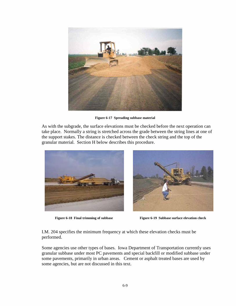
6-9
Figure 6-17 Spreading subbase material
As with the subgrade, the surface elevations must be checked before the next operation can
take place. Normally a string is stretched across the grade between the string lines at one of
the support stakes. The distance is checked between the check string and the top of the
granular material. Section H below describes this procedure.
Figure 6-18 Final trimming of subbase
Figure 6-19 Subbase surface elevation check
I.M. 204 specifies the minimum frequency at which these elevation checks must be
performed.
Some agencies use other types of bases. Iowa Department of Transportation currently uses
granular subbase under most PC pavements and special backfill or modified subbase under
some pavements, primarily in urban areas. Cement or asphalt treated bases are used by
some agencies, but are not discussed in this text.

6-10
E. Pad Line, Track Line, and Form Line
All of these terms are often used to describe the area outside the edge of the proposed
pavement that provides the foundation for all the paving equipment operations.
Most contractors believe that this line is one of the major keys to smooth pavement and
should encompass the following characteristics:
The base itself should be extended to a point at least three feet (one meter) beyond the
outside edge of the pavement.
The base should be constructed or trimmed parallel to the projected cross slope of the
base. The creation of parallel lines is essential in minimizing the yield loss. In
addition, parallel planes ensure both the agency and the contractor that the proper
thickness of pavement will be placed over the entire roadbed.
The base should be durable enough to provide a relatively smooth passage for the
entire paving train. The placement of edge drains or subdrains beneath the track lines
(longitudinally) prior to paving should be avoided. The weight of the paving
equipment can crush the drainage pipes. Most agencies allow the contractor to place
these drains after placement of the pavement.
The line should be kept clean of dirt, debris, and surplus concrete during the
pavement operations.
Figure 6-20 Base material extended beyond pavement edge
to form pad line
Figure 6-21 Paver track on pad line
F. Placement of Dowel Baskets
Article 4151.02 & 2301.03, E
Road Standard PV-101
Once the base has been trimmed to grade and the inspector is satisfied that the base surface
has been brought to the proper profile, the contractor can begin to place the dowel baskets.

6-11
The contractor will then place the baskets on the grade, align them properly, and stake them
down according to the PV-101 road standard.
Positioning will normally begin at a header but often must be adjusted in order to match side
roads, crossovers or taper locations. Both contractor personnel and agency inspectors must
think ahead as to where joints will be sawn and make sure they match properly with existing
joints in existing abutting pavement
Basket stakes should be placed so the vertical portion of the stake is behind the basket wire,
relative to the direction of paving. This supplies support as concrete pushes against the
assembly.
Figure 6-22 Staking down the basket
Figure 6-23 Pins placed behind the basket (paving
direction is from top to bottom of of photo)
At the contractor’s option, up to three tie wires may remain uncut on each CD basket
assembly. If they are cut, the inspector should approve their placement before they are cut in
order to avoid risking loss of the basket if they must be repositioned.
Figure 6-24 Cutting the tie wires is a contractor option

6-12
The position of the bars is critical since the joints open and close throughout the year. If the
bars are not truly aligned, both horizontally and vertically, they may bind up when this
movement takes place and this can crack and break the pavement.
A final check would include the following:
Sight down the grade. All the dowels should look straight as you look down the road
at rows of assemblies. If they are not straight, it is easy to pick out the ones that are
misaligned.
Figure 6-25 Sight down the grade to check dowel alignment
Sight across the assemblies. All the dowels should be level and at the same elevation.
If the grade was trimmed with a small trimmer which required two passes, the base
may not match at the center. This can lead to the two assemblies not matching, with
the end dowel of one being higher than the adjacent end bar of the other center. Also
look for bars that are not level or have been bent down. These need to be straightened
or replaced.
Sighting across the basket from one pin or mark toward the one on the other side of
the road. This is the line the saw will follow and should run across the middle of the
basket for the entire length. If one of the assemblies is slightly off alignment, the saw
cut can wander off the middle and result in an insufficient length of dowel on one side
of the joint. This can lead to inadequate load transfer and early cracking of the new
pavement.

6-13
Figure 6-26 Dowels not level
Figure 6-27 Dowels not aligned across joint
In some fashion, marks will be made to show the exact locations of each assembly
outside the edges of the pavement. Often pins are set on either side of the roadway to
mark the locations. Some contractors simply paint marks in the rock on either side.
The inspector should spot check the spacing to make sure they are properly spaced
and aligned.
Figure 6-28 Paint mark to locate joint for sawing
Dowel bars are required to be dipped in a bond breaker material prior to being
delivered to the site. The bond breaker material may be either a bituminous material
or a paraffin material. The paraffin material is normally clear so the bars look green.
When bituminous material is used, the whole assembly looks black. The inspector
should check the bond breaker to make sure that it is not weathered or worn. If the
bond breaker is showing signs of weathering or wear, the basket should be recoated.
There are several options for recoating bars including returning them to the
manufacturer to be redipped or spraying with form oil or other approved material.

6-14
Figure 6-29 Paraffin coated bars at top and bituminous coated bars at bottom of photo
G. Paver Checks
Form 830213
Before paving operations begin, it will be necessary for the PCC Grade Inspector to check
the screed on the paving machine. With the screed set for a normal 2% crown, the Inspector
will be able to pull a level line across the width of the screed. Utilizing the plan cross slope,
the Inspector will be able to calculate an offset distance between the level line and the bottom
of the screed. For instance, if you measure 4 feet (2 m) from the outside edge of the slab and
the rate of cross slope is 2%, the offset distance from the level line and the bottom of the
screed will be 0.08 feet (40 mm). If there is any deviation, the screed will need to be
corrected.
The same method can be used for ramp paving. Pull a level line from the low end of the
screed and measure the offset distance from the level line and the bottom of the screed.
There will be no crown in the ramp so the same rate of cross slope will be used for the entire
length of the screed. It is a good idea for the Inspector to get acquainted with how the
Contractor changes the cross slope of the screed. This is commonly referred to as “Dialing in
the Cross Slope.” If the Inspector is aware of how this is done, they will be able to notice a
discrepancy if one should occur. The screed should also be clean from any debris before it is
used.
Project Information /Paver Inspection form 830213 is to be filled out prior to paving with a
slip-form paving machine. A sample form is included in the Appendix. Usually this is done
one or two days prior to paving for different machine widths or configurations to document
machine and vibrator set-ups. Then during paving, this same form can be used to document
daily vibrator checks.

6-15
Figure 6-30 Paver inspection form 830213
This form is started when the contractor notifies the inspector that the paver is assembled and
set at the correct width. The first thing to check is the actual width of the paver. Generally
the paver will be set slightly narrower than the proposed width to allow for expansion of the
plastic concrete as it comes out of the paver.
Next, beginning on the left side (looking forward from behind paver) measure and record the
distance and spacing of each vibrator. This information, along with the approximate angle of
the vibrators and clearance between vibrators and the bottom of the paver pan, is to be
included on this form.
Figure 6-31 Checking the vibrator spacing
Figure 6-32 Sphere of influence of a vibrator

6-16
H. Determination of Subgrade and Subbase Elevations
Section 2111
1. Subgrade
Generally the inspector will be responsible for checking the base once it has been cut to
the proper elevation by the contractor. Standard specification 2111.03, B states that the
tolerance is 0.05 foot (15 mm) high or low. This can be simply checked with a string, 6-
foot ruler, and a set of plans.
Some definitions are given below for terms that will need to be understood in order to
check the accuracy of the subgrade and base. Based on the machinery clearances,
working conditions, and haul road locations, the contractor determines the offset. The
machine constant is used to give the contractor’s equipment clearance above the
stringline pins and survey control.
DEFINITIONS
OFFSET: The distance from the survey control stake to the edge of the pavement
PROFILE GRADES: The elevation at the top of the proposed pavement. The
plans must be checked to insure the location of this grade. In some cases it is defined
at the edge of the pavement but traditionally it is the centerline of the roadway
LEVEL GRADES: Survey elevation control referenced level across the
distance of the offset
EXTENDED GRADES: Survey elevation control referenced by extending the
pavement cross slope across the distance of the offset

6-17
MACHINE CONSTANT: The distance the contractor sets the stringline above
the survey stakes in addition to the survey information.
First check the height of the wand above the hub. This should be the elevation of the hub
plus the machine constant. Hook one end of a string to the control string line pin.
Running the string under, and intact with control string line, over to the pin directly
across the roadway. Your string will be perpendicular to the centerline of the roadway.
Care should be used to insure that your string is tight enough to eliminate sag, but not too
tight as to cause distortion in the control stringline and/or pins. Measure from the hub,
towards the centerline, the width of offset on the survey stake and mark this location for
each side. These points are the outside edges of the proposed pavement. Next measure
the vertical distance from the stringline to the top of base and record this distance.
To calculate what this dimension should be, you would need the typical cross-section and
survey information for the station that is being checked. Also needed is the constant
distance that is used by the contractor for clearance to prevent the equipment from hitting
the control stringline and pins. Remembering that the survey stake is referenced to the
top of slab, start with the constant that the contractor is using. Add to this the thickness
of the pavement. Then add the subbase thickness. This is the desired distance from
string to top of subbase.
Machine Constant + Pavement Thickness + Subbase Thickness = Desired Distance
Compare the actual distance to the desired distance. Document the difference and notify
the contractor of any corrections needed. Re-check after corrections in the same manner.
On some projects, when the grading is done separately from the paving, the grade is
accepted on the basis of the blue-top stakes. This process will vary from office to office,
and factors like wintering of the grade should be taken into consideration.

6-18
2. Subbase
After the subgrade is accepted, the contractor will begin to haul subbase on to the grade
and begin compacting and cutting to grade. Standard Specification 2111.03, D states that
the tolerance is 0 high and 0.05 ft. (15 mm) low. This elevation can be checked in a
similar fashion, with the exception of a few differences in calculating the desired
elevation. Attach your stringline as before and mark the edges of the slab using offsets
on survey stakes as before.
This check also requires that the center of the proposed roadway be located, since a check
will be required there as well. Measure from the string to the top of the subbase at both
edges of the proposed pavement, as well as the centerline, and record these
measurements.
To calculate what this dimension should be, again you will need typicals and survey
information from the hub. Also you will need the contractor’s constant which may or
may not be the same as for the subgrade check. Once again, remembering that the survey
information is referenced to the top of the slab, start with the constant that the contractor
is using.
Next add the thickness of the pavement. This would be the desired measurement for the
outside checkpoints. For the centerline point you will need to remember that the subbase
will generally mirror the top of the slab so it is necessary to account for the cross slope
and/or the crown. To determine this, use the cross slope shown on the hub and multiply
by the distance to the centerline. This will be a negative or positive adjustment,
depending on whether there is a crown or superelevation.
Machine Constant + Pavement Thickness +/- Proposed cross slope * distance between
edge and centerline
Compare actual distance to the desired distance. Document the difference and notify the
contractor of any corrections that are necessary. Re-check after the corrections are made
in the same manner.

6-19
Figure 6-33 Subgrade/Final Grade Check Form E109
Subgrade and subbase elevation checks should be recorded on Form E109.

6-20

CH
AP
TE
R 7
PA
VIN
G O
PE
RA
TIO
NS


7-1
Chapter 7 Paving Operations
A. Wetting the Grade
Wetting the grade is a very important step, but can easily be overlooked. It is especially
important in hot, dry, or windy weather. A dry subgrade draws water from the concrete
which can lead to inadequate strength gain and increased risk of cracking.
Figure 7-1 Wetting the grade
If there was sufficient rain the day before, wetting the grade may not be necessary.
Overwetting the grade is not desirable either. The surface should be noticeably wet but need
not be wetted to the point of water standing
B. String Line Control
As discussed in chapter 7, string lines are used as a means to control the elevation and
alignment of many pieces of equipment. The trimming that is done prior to paving uses these
as guidance. The spreader and paver also use them. Normally string lines are used on each
side of the grade to control elevation and one of the strings is used as guidance for the
machine. The tining/cure machine also runs off the string lines.

7-2
Figure 7-2 Spreader and paver with guidance from
stringline
Figure 7-3 Adjust sensor arm to raise or lower paver
As people walk around the paving operation, they must be very careful of the string lines. If
a string is bumped, it can be knocked out of alignment and cause the paver to create a dip or
hump in the slab. People also need to be careful not to knock the wand off from the string.
The wand is the controlling mechanism for the machine and if the wand is loose, it will cause
the machine to either rise or fall. That will create additional work for the contractor because
the new pavement will have to be fixed, either by backing the paver up and going over the
section again or by sawing it out later and replacing it.
Care needs to be taken when walking around the string lines for the safety of the inspectors
and contractor’s personnel. If one would trip over it, it would be easy to fall onto the haul
road and serious injury or worse could result.
C. Deposit and Spread Concrete
On thicker pavements and almost all Iowa Department of Transportation projects, dowels are
required. The dowel basket placement on the grade and restrictions against driving on the
base material lead to the concrete being delivered from the haul road and then placed out in
front of the paver. The belt placer is used to accomplish this operation. It places the concrete
near the center of the roadway and then, with augers, spreads it across the width of the
pavement at a fairly uniform thickness. This helps create a uniform amount of concrete going
into the paver which helps create a smoother pavement.

7-3
Figure 7-4 Spreader to distribute concrete across the grade
D. Place and Consolidate
Article 2301.03, F
The paver is the heart of the paving operation. As discussed in Chapter 5, it forms the slab to
the desired dimensions, and it consolidates the concrete. If correctly done little effort will be
required by the finishers.
Figure 7-5 Concrete entering the paver
E. Finish
Article 2301.03, H

7-4
When everything (mix, equipment, timing, delivery, etc.) is substantially correct, no finishing
other than the texturing would be required. However, many things can happen to this
outdoor assembly line process requiring correction in the final phase.
Finishing should not be undertaken while any bleed water is present. Under some weather
conditions or with some mix peculiarities, bleed water can be significant.
1. Mechanical Floats
Several pieces of equipment may be utilized to correct minor variations and help seal any
small imperfections in the finished slab surface. Combinations of these tools may be
utilized on the same slab.
The longitudinal float or oscillating screed float, which may either be attached to the
paver or self-propelled, is a float that may be up to 12 inches (300 mm) wide and 12 to 15
feet (4 to 5 meters) long. This float is normally placed parallel or close to parallel with
the centerline of the slab. The float is carried from one side of the slab to the other while
being oscillated front to rear. This is commonly termed the final finisher.
Figure 7-6 Oscillating screed float
The Lewis float or V float consists of a truss with floats attached to the bottom normally
attached to the paver near the centerline and fanning out toward the edges of the
pavement. This truss has a narrow float attached to the edges. This float rests on the slab
and can be pulled by the paver.

7-5
Figure 7-7 V float
A burlap drag may be attached to the paver to help close the surface. Water is applied to
the burlap and should be applied in limited amounts. A good indicator of too much water
added to the burlap is the appearance of small bubbles on the trailing edge of the burlap.
Figure 7-8 Burlap drag used to help close the pavement surface
2. Straight Edge and Hand Float
Checking the surface behind the paver with a 10-foot straight edge is required. Should
any surface imperfections be found, they should be corrected with a hand-operated float.
Periodically check the trueness of the straightedge with a stringline.

7-6
Figure 7-9 Straight edge and hand float
3. Edge Slump
Out-of-tolerance edge slump, for whatever cause, will have to be corrected by the
finishers by placing a bulkhead against the slab, adding some concrete, and floating the
surface.
Today’s pavers are equipped to overbuild the edge area and to allow a certain amount of
sag to occur as the slab leaves the traveling form. When the mix is within prescribed
limits for air and slump, the edge is normally acceptable.
Figure 7-10 Straight and true edge with no edge slump

7-7
4. Water on the Surface
Excess water, if worked into the surface, can cause plastic shrinkage, excessive water
cementitious ratio at the surface, and eventual scaling of the surface.
Water shall not be used in any significant amount to close the surface. If the surface is
not closing well, the entire operation must be reviewed, including paver adjustments,
increasing the mixing water, and changing the aggregate gradation.
Figure 7-11 Ridge of slurry coming from the screed
Equipment breakdowns cause delays that can put a burden on the finishers, but even then,
water usage must be strictly limited. The burlap drag may be kept moist, but not sloppy.
If trails of bubbles are observable behind the drag, it has excessive free water. Also, if
slurry is forming along the edge of float or slurry is collected by the float and runs down
the edge of the slab, excessive water is being added to the surface, and this practice
should be stopped.
Figure 7-12 Surface scaling resulting from excessive moisture on pavement surface

7-8
5. Rumble Strips
Most new primary road pavements are built wider than the traveling lanes. They include
a two-foot (0.6m) piece of pavement on the outside edge that is considered part of the
shoulder. This is called a widening unit and must have a rumble strip constructed along
it. When continuous milled shoulder rumble strips are not included on the project,
structural rumble strips are placed by hand in the two foot widening. The purpose of the
structural rumble strips is to keep traffic from driving on the widened portion of the
pavement. This helps to reduce stresses on the pavement edge. Occasionally contractors
forget to stop placing rumble strips in areas where they are not required such as along
turn lanes, side road connections or ramp tapers. Check the plan before the project
begins and discuss this requirement at the preconstruction conference as well when the
project begins.
Figure 7-13 Structural rumble strips placed in widening
Figure 7-14 Milled shoulder rumble strips placed in
widening
6. Marking Joints
To aid in sawing, the joint locations are identified. Some contractors use a rope or chain
to score the joint location into the pavement surface after finishing and texturing. This is
less common than in the past since contractors have discovered that scoring the pavement
surface has an impact on pavement smoothness. Now, a more common practice is to
place a paint mark and/or basket stake off each end of the basket prior to paving. The
joint is then marked later using a chalk line so the saw crew will have a line to follow
when sawing the transverse joints.

7-9
Figure 7-15 Paint line to mark joint location for basket
placement and sawing
Figure 7-16 String used to score the surface as a mark for
the joint sawing
F. Texture
Article 2301.03, H
After finishing operations are complete, a two-step texturing process is accomplished. The
first step is applying the microtexture to the surface. This is done to roughen the surface and
provide more grip with the tires to assist in stopping on dry pavement. The second is the
construction of the macrotexture through the placement of small grooves in the surface of the
plastic concrete. This breaks the smooth surface and allows water to escape out from under
tires during a rain and thereby reduce the tendency for hydroplaning.
1. Microtexture
Microtexture is achieved by use of a turf drag, coarse carpet, or burlap. This drag can be
attached to the front of the tining machine but is normally attached to a small bridge. If
the bridge is used, the paver should pull it. It will be some distance back, which will
allow room for the finishers. Having the bridge pulled by the paver will result in a
uniform forward motion and create a straight, uniform microtexture pattern. Only during
unavoidable circumstances should the bridge be pushed forward by workers. Often hand
pushing results in a back and forth pattern on the pavement surface, which is very visible
to motorists for the life of the pavement.

7-10
Figure 7-17 Turf drag for microtexture Figure 7-18 Burlap drag for microtexture
2. Macrotexture
Most states require tining to increase the friction of the surface of the pavement. Placing
macrotexture in the pavement surface is typically accomplished by transverse or
longitudinal tining. Today, longitudinal tining is most commonly used because it is a less
labor intensive operation than transverse tining and still results in acceptable friction
levels. The inspector should review Article 2301.03, H to determine current acceptable
tining requirements and discuss this with the contractor.
Figure 7-19 Longitudinal tining
The tining machine must be parallel to the pavement surface. If not, an uneven pressure
will be exerted on the pavement surface, resulting in a non-uniform texture. The depth of
the tining should be as shallow as practical, within the specification. Shallow texture
results in less noise being generated by the tire-pavements interaction while still
providing adequate friction.

7-11
In some cases the transverse texturing machine is designed to rise from the pavement
surface several inches (millimeters) away from the edge of slab. This preserves edge
integrity and alignment.
When transverse tining is used, the area along either side of the proposed joint location is
not textured. This provides an excellent surface for sawing and sealing operations. For
longitudinal tining, a blanking band is not required. When placing transverse tining,
overlapping of the texturing should be avoided because the resulting thin fins will be
extremely fragile.
Figure 7-20 Placing the blanking band ahead of tining
Figure 7-21 Transverse tining
G. Curing
Article 2301.03, K
An important step in concrete paving is the curing process. The surface and edges of the slab
are sprayed with curing compounds to retard the loss of moisture from the concrete. The
standard curing material for pavements is white pigmented curing compound. Curing
compounds that are visible when applied provide a visible opportunity to determine
uniformity of placement.
The curing compounds should be thoroughly mixed and continually agitated. Larger paving
projects usually utilize bulk delivery and storage. The bulk storage is normally air agitated,
and the spray machine tank is stirred with electrically driven paddles. Today curing
compound is commonly delivered to the project site in reusable totes. Smaller deliveries
are usually in barrels.
The rate of cure application in gallons per square yard (liters per square meters) should be
checked routinely. Be sure to apply the cure to vertical slab edges and include them in rate
calculations.

7-12
Figure 7-22 Curing operation
Figure 7-23 Curing compound delivered in reusable
totes
H. Headers
Article 2301.03, J
Road Standard PV-101
A header is constructed when the contractor ends a section of pavement. They are placed at
the end of a day’s run and whenever the paving operation is stopped for more than 30
minutes. A header is normally a hand poured area that is placed beyond where the paver
pulled away from the slab. It consists of a header board and tie bars. Each tie bar is placed
partially in the fresh concrete and partially sticking out beyond the header board. These
protruding ends will then be incorporated into the next section of pavement.
Figure 7-24 Hand placement and finishing of header
Headers cannot be placed within five feet of a contraction joint. The header board normally
has pre-drilled holes at the location where the tie bars are to be placed. Care must be taken to
insure that the bars are parallel with centerline and level.

7-13
The header board is placed at the location of the header. The area behind the header board is
filled with concrete. The concrete is vibrated and finished. The surface is textured and
cured. The date should be placed at all header locations to properly identify the date of
placement.
Figure 7-25 Header with date stamped in each placement
An alternative method to construct a header is for the contractor to pave beyond the location
of the header and leave the end of the pavement irregular. The next day a full depth saw cut
is made at the location of the header and the irregular portion removed. Holes will be drilled
into the smooth face of the pavement end, and the tie bars will be anchored into the slab.
This method is used to reduce the likelihood of a bump at the header.
Figure 7-26 Run out header
Figure 7-27 Previous day's header
The inspector must watch for delays or breakdowns that stop the paving operation. This can
happen either to a piece of equipment on the paving train or at the plant, which stops the
delivery of concrete. Once the paver is stopped for 30 minutes, a header must be placed. In

7-14
an effort to buy time while repairs are being made, the contractor may elect to slow the paver
to a crawl. This is acceptable as long as the time for placement of the concrete does not
expire. Communication between the field inspector and the plant, in order to determine batch
time of the concrete loads, is critical.
If a header is placed, a contractor often will then resume paving, when the equipment
problem is solved, by pulling the paver ahead some distance and beginning again. This will
leave a gap between the ending header and the beginning header that will be filled in at a
later time as a patch.
I. Hand Pours
Hand pours are areas of paving which are not placed with a paver. They are constructed by
placing the concrete on the grade, within the confines of forms and/or existing pavement.
The concrete is struck off and vibrated with hand methods. This type of construction is used
in irregular areas such as radii, ramp tapers, and gaps.
The forms must be checked for proper alignment and straightness. The depth of the concrete
can be checked prior to placement by stretching a stringline across the top of the forms and
measure down to the base material.
While there are no slump requirements for slip form paving, there are limitations on slump
for hand pours. Also, the vibrator requirements are different for hand pours.
Figure 7-28 Hand pour in an irregular area
Figure 7-29 Hand pour at bridge approach
J. Cold Weather Protection
Article 2301.03, K

7-15
Article 2301.03, K dictates the type of protection needed for concrete paving. It is necessary
for the grade inspector to obtain the projected low temperatures to assure the paving is being
protected adequately. An easy way to obtain this information is from a local radio station.
At times the contractor will use a weather service to obtain this information also. Normally
these temperatures will be the overnight temperatures.
Figure 7-30 Burlap covering for cold weather protection
Article 2301.03, S dictates the concrete and air temperatures required for the contractor to be
allowed to pave. The grade inspector will need to actually carry a thermometer and take the
air and concrete temperatures to be sure the contractor is in compliance with the
specification. The problem with using the current air temperatures from a radio station is the
station may be a fair distance away from the project and there could be a difference in
temperatures between the two locations. Another problem is the station is probably in town
where the temperatures are normally warmer than what they are on a rural paving project.
It is necessary for the inspector to record these temperatures and the time they were taken. If
any action is taken such as not allowing the contractor to start or having them shut down, this
should also be documented in the inspector’s diary.

7-16

C
HA
PT
ER
8
TR
AF
. CO
NT
. & S
AF
.


8-1
Chapter 8 Traffic Control & Safety
A. Traffic Control
Traffic control is an integral part of safety on a construction project. While inspection and
maintenance of traffic control devices is the contractor’s responsibility, an inspector should
always bring deficiencies to the contractor’s attention so repairs or changes can be made to
provide a safe work zone for everyone. The inspector should also encourage the contractor
to make these repairs or changes as quickly as possible to minimize the risk of incident.
Figure 8-1 Inform the contractor of any traffic control deficiencies
B. Safety
Section 1107
Safety is everyone’s job. The inspector needs to be alert to any activities that may pose a
safety concern. The contractor is responsible for safety on the project site but the inspector
should always be on the alert and immediately bring to the attention of the contractor
anything that needs to be changed or improved.
The Contractor’s machines and equipment should all be in good mechanical condition. This
should also include any safety guards required for the equipment. The inspector will not
actually use the Contractor’s machines or equipment, however they will be working right
along side of it. The safety of the inspector and the contractor’s personnel depends on their
safe operating condition.
Any time anyone must walk near the spreader belt, they need to be cautious. Trucks are
backing up to the belt and can’t see someone that may be standing between the truck box and
the spreader. Also one should never walk under the belt when it is in the upright position.
The hydraulics can fail and the belt can simply fall without notice.

8-2
Figure 8-2 Be cautious when near trucks backing
up to the spreader belt
Figure 8-3 Never walk under the spreader belt when it is in the
upright position
The condition of the haul roads used by the contractor should also be inspected. The
contractor has the responsibility to maintain dust control on these roads. Normally a water
truck is used to periodically spray water on the road. If dust begins to make visibility
difficult, the inspector should have the contractor water the haul road more frequently.
Figure 8-4 The contractor must water the haul road to control dust
If the construction is immediately next to traffic, a greater degree of awareness of one’s
surroundings is required. Anyone that must be next to an open lane must always be aware of
where they are relative to the passing traffic. The picture at the right illustrates what can
happen if the float handle is struck by the passing truck. If the handle is on the upstream side
of his head, he could be seriously injured if a passing vehicle struck it.

8-3
Figure 8-5 Be alert when working near traffic
The string line is also a hazard. If someone trips over it and falls, they could fall under a
passing vehicle.
Figure 8-6 The stringline can be a tripping hazard
The inspector and the Contractor must designate areas for parking vehicles. Parked vehicles
can be an obstruction to both the construction vehicles and the motoring public. Normally
vehicles should not be parked on the shoulder of open roadways. If they can be pulled down
into the ditch and out of the way, this may work as a temporary location.

8-4
Figure 8-7 Park vehicles in safe areas away from traffic
During shouldering operations often dirt must be excavated and hauled to the project
location. Although it is not the inspector’s job to direct the contractor's actives, if an unsafe
condition becomes evident, the inspector should not let it go on with out reporting it. The
picture illustrates an unsafe condition where a collapse of the embankment could be
disastrous for both the backhoe operator and the truck driver.
Figure 8-8 Unsafe conditions need to be reported
If any violations of the specifications or any safety problems are noticed, the inspector should
notify the contractor immediately. The inspector should also notify the inspector in charge of

8-5
the project as soon as possible. Any violations or problems and conversations with the
contractor about them should be noted in the inspector’s diary.
The contractor’s plant site also poses many safety concerns. Often during high production, a
contractor may batch up to four hundred truck loads of concrete every day. This means that
not only will the trucks hauling the four hundred loads of concrete to the paver be cycling
through the plant site, but the trucks delivering the unmixed materials to the plant site will be
cycling through also.
Because the plant site is such a busy place it is easy for an inspector or their vehicle to be
forgotten or overlooked. It is very important that when visiting a plant site, an inspector
make sure that they are seen by all. To stand out as much as possible, a safety vest should be
worn at all times. Vehicles should be parked in a conspicuous location away from the haul
routes of the delivery vehicles. Production vehicles should always have the right of way
unless the driver clearly motions for the inspector to proceed.
Figure 8-9 The plant site poses many safety concerns
Because there is equipment and materials overhead at the plant site, a hard hat must be worn
at all times when on foot. As a policy, most contractors require this of their employees as
well as all visitors.

8-6

CH
AP
TE
R 9
RO
LE
OF
TH
E IN
SP
EC
TO
R


9-1
Chapter 9 Role of the Inspector During Paving
Prior to the day of paving, the inspector should assemble the testing equipment and tools that
will be needed for testing and inspection. These items include an air meter, a siphon bottle, a
bucket, a rubber mallet, a shovel, a slump cone, a long rod, a margin trowel, and a set of station
numbers.
The air meter should be calibrated and in working order. As with any equipment, care needs to
be taken in handling and transporting the meter. It is best to leave the meter at your job trailer
until it is needed. To insure air content readings are accurate, calibrate your air meter regularly.
Figure 9-1 Assemble and check testing equipment
Prior to the day paving begins an inspector should have checked the grade, the dowel basket
placement, and the equipment. A visual check should be made of the roadway area to be paved
that day. This should include looking for debris on the grade, dowel bars that have been bent out
of position, wetness of the grade, and eyeballing the stringline for any inconsistencies. This can
simply be accomplished by periodically walking out ahead of the paving train throughout the
day. When problems are identified, the contractor should be notified immediately to allow time
for correction.

9-2
Figure 9-2 Check grade conditions before start of paving
It is good to check the most recent weather forecast and be prepared for any changes in the
weather conditions. If there is any chance of rain, discuss it with the contractor. Plastic or
burlap should be readily available to use for protection of the concrete from rain damage.
A. Traffic Control
Section 2528
The contractor is required to review the traffic control for the project and document its
condition. If there are corrections or repairs that need to be made, they should be noted in the
contractor’s traffic control daily diary. The contractor should also document when the
corrective action was taken. This information may be needed at a later time. This
information is critical in case an accident would occur.
Even though the contractor is responsible for maintenance and repair of traffic control, the
inspector should bring deficiencies to the contractor’s attention when discovered. If
corrective action is not made within a reasonable timeframe, a non-compliance notice should
be issued.

9-3
Figure 9-3 Traffic control devices are often hit, moved,
or destroyed
Figure 9-4 Notify the contractor of devices in disrepair
After paving has begun, the contractor and inspector should observe the traffic patterns of the
delivery vehicles and especially how safely they interact with public traffic. If it appears that
the operation needs to be revised in order to make it safer, the inspector should discuss
possible changes with their supervisor and the contractor.
Everyone associated with the traffic control for the project must be notified of any changes.
The contractor must note in their traffic control daily diary any changes if a revision was
implemented.
B. Wetting the Grade
Wetting the grade is a very important step, but can often be overlooked. It is especially
important in hot, dry, or windy weather. A dry subgrade draws water from the concrete
which can lead to inadequate strength gain and increased risk of cracking.
Figure 9-5 The grade must be wet ahead of the paver

9-4
If there was sufficient rain the day before, wetting the grade may not be necessary.
Overwetting the grade is not desirable either.
C. Concrete Delivery
Articles 2301.02, C, & 2001.21
There are a number of inspection duties that the inspector must be continuously watching
with regard to the concrete being delivered to the grade.
1. Delivery Time
There are three methods of transporting the concrete to the grade: with regular dump
trucks, agitators, and transit mixers, better known as ready mix trucks. Article 2301.02,
C provides the discharge times for all three methods. In brief summary, concrete
delivered to the grade without continuous agitation must be placed within 30 minutes but
concrete delivered to the grade with continuous agitation must be placed within a period
of 90 minutes. Concrete delivered in a ready mix truck also must be placed within 90
minutes.
Figure 9-6 Dump truck - 30 minute time limit
Figure 9-7 Agitator truck - 90 minute time limit
When a stationary mixer is used, the grade inspector will have to go to the plant site and
document the batched time. This will be the time when all of the materials are placed in
the mixer as per Article 2001.21. The inspector will then follow the truck to the paving
site and document the time of discharge. The time interval must not exceed the specified
time for discharge for the type of truck the mix is being hauled in.
With a ready mix truck the time batched will be on the ready mix ticket. The plant
inspector will fill out this ticket. The time discharged is when the ready mix truck is
finished discharging the load. This time will be recorded on the ready mix ticket by the
grade inspector. This time cannot exceed 90 minutes.

9-5
Figure 9-8 Ready mix truck - 90 minute time limit
2. Added Water
When necessary, the contractor can add water to the concrete at the grade if a ready mix
truck is being used. Per Article 2301.02, C, the concrete must be mixed at least an
additional 30 revolutions if water is added at the grade. It is necessary for the inspector
to count and assure that these additional revolutions are performed to insure proper
mixing.
Figure 9-9 Water can be added to a ready mix truck at the grade

9-6
When water is added to a ready mix truck the grade inspector must be sure total water
does not exceed maximum water allowed. This maximum water allowed will be entered
on the ready mix ticket by the plant inspector. It is necessary for the grade inspector to
communicate with the plant inspector on a daily basis to let them know how much water
has been added at the grade. The plant inspector will then use this information to
calculate the water/cement ratio.
3. Mixing
Concrete delivered by the first two methods is mixed in a stationary batch plant and then
dumped into the trucks. The concrete delivered by a ready mix truck will be mixed in
either a stationary batch plant and then discharged into the truck or mixed in the drum of
the ready mix truck itself.
At any time the grade inspector notices or suspects that something is not right with the
mixing operation or the concrete itself, the inspector should contact their supervisor and
the contractor immediately and document it in the daily diary.
4. Clean Boxes
Throughout the day the inspector needs to watch the inside of the delivery truck boxes.
Concrete can, and often does, stick to the inside of the box, particularly in the corners.
The contractor and the inspector need to make sure that all the concrete falls out of the
truck when each load is emptied at the grade. If concrete sticks to the box, the box
should be cleaned out before the next batch is dumped into the truck. This is important
because this concrete will ride along the truck all day and, at some point, may come loose
and end up in the pavement.
Figure 9-10 Concrete stuck in box must be removed before next batch is loaded

9-7
D. Placement
It is important to watch the concrete as it piles up under the belt placer. The pile should be
somewhat bell-curve in shape. Segregation of the concrete can occur as it comes off the belt.
If this occurs the pile will be more vertical on the side away from the belt and more flat
toward the belt. The larger aggregate is being thrown further and the paste is running off the
end to the belt. This can effect how well the edge of the slab stands up. Normally the edge
next to the delivery will slump more than the side away from where the trucks dump.
Figure 9-11 Uniform concrete pile - not segregated
E. Concrete Testing
I.M. 327, 204
Construction Manual 9.61
I.M. 204 dictates the minimum frequency requirements of testing. I.M. 327 explains how
and where to obtain samples. Paragraph 9.61 of Chapter 9, PCC Pavement, in the
Construction Manual also addresses concrete sampling.
1. Air Content
Article 2301.02, B
I.M. 318, 327, 527, 204, 530
The air content is an important property of the concrete because it has a great impact on
how long the concrete will last. Therefore tests are made of the concrete during the
placement operation to insure that the proper air content is maintained. I.M. 530 along
with I.M. 204 or the Supplemental Specification for QM-C projects, specify the
minimum testing frequency that must be followed.

9-8
Specification 2301.02, B discusses the required percent of entrained air needed for
concrete paving mixes. The concrete paving mixes have been developed so finished,
consolidated concrete contains 6% air content. To allow for air loss throughout the
paving operation, specifications require the air content for fresh, unvibrated, plastic
concrete to be between 6 and 10% before consolidation, with a target of 8%.
Figure 9-12 Air meter
Figure 9-13 Air test on grade
Newer, heavier slipform paving equipment can sometimes cause an entrained air loss
greater than 1.5% due to their higher ability to impart vibration forces into the plastic
concrete. For this reason the specifications allow for checking of air content behind the
paver to ensure that adequate air content remains in the concrete after consolidation. If
adequate air content does not remain, the target air may be adjusted. Air content behind
the paver should be checked daily until inspection staff is comfortable that air loss is
consistent.
Figure 9-14 Sampling concrete behind the paver

9-9
The amount of air entraining agent that is dispensed into the mix at the paving plant is the
contractor’s responsibility. The inspector should not recommend dosage rates but should
inform the contractor of non-complying or near non-complying air content.
2. Slump
Article 2301.02 B.
IM 204, IM 317
Slump is a test that was used in the past to give an indication of the change in water
content of the concrete. Today it may not always do that because admixtures can affect
the slump without changes in the water content. Often the slump test is used to
approximate the workability or flowability of the concrete. This too is inexact because
the workability may not always be reflected by slump characteristics.
The slump test is best used to measure consistency of a given concrete mixture. Current
slump limits are given in Article 2301.02, B and the testing frequency is given in IM 204.
For slip form paving, the slump test is not required.
Figure 9-15 Record air and slump test results on Form E115
3. Mix Temperatures
Article 2301.03, S

9-10
Because of the important influence temperature has on the properties of freshly mixed
concrete, some specifications place limits on temperatures. In Iowa, the minimum mix
temperature for concrete paving is 40 degrees F (4 degrees C).
The contractor or inspector can measure the concrete temperature at any time, although
no frequency is specified. The change in temperature can relate to changes in air content,
water demand, and workability.
Figure 9-16 Thermometer inserted into the concrete in the air pot
F. Pavement Testing
1. Edge Slump
Article 2301.03, H
Construction Manual 9.53
There are times when the moisture level of the aggregate brought into the plant site varies
greatly. The individual loads may have lower or a higher moisture level then what was
being used previously. Also there may be a wet pocket of material in the stockpile. The
Plant Inspector may not notice this until they do a moisture test. A wet pocket in the
stockpile may only affect a load or two and no corrective action will be necessary.
If the aggregate that is brought into the plant site is consistently higher in its moisture
content, then the water added at the plant site may need to be adjusted. It is this increase
in water in the concrete that can lead to edge slump.
Article 2301.03, A states that a slip form paving machine should be used that leaves the
edges of the slab vertical. If the edge of the pavement begins to slump, it may need to be
supported by a temporary form. This form should also meet the specifications for forms
as stated in Article 2301.03, A. Section 9.53 of the Construction Manual covers the use
of forms for repairing excessive edge slump.
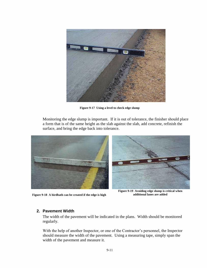
9-11
Figure 9-17 Using a level to check edge slump
Monitoring the edge slump is important. If it is out of tolerance, the finisher should place
a form that is of the same height as the slab against the slab, add concrete, refinish the
surface, and bring the edge back into tolerance.
Figure 9-18 A birdbath can be created if the edge is high
Figure 9-19 Avoiding edge slump is critical when
additional lanes are added
2. Pavement Width
The width of the pavement will be indicated in the plans. Width should be monitored
regularly.
With the help of another Inspector, or one of the Contractor’s personnel, the Inspector
should measure the width of the pavement. Using a measuring tape, simply span the
width of the pavement and measure it.

9-12
Another method the Inspector can use is to measure the distance from the paving hub to
the edge of the slab. This distance should be the offset distance written on the flat for the
paving hub.
The Inspector will need to measure from the two hubs at the same station location to use
this method. Slight deviations may occur if the paving hub has been disturbed. If the
Inspector notices a hub that looks like it may have been disturbed, use a different location
or method. Again, notify the Contractor and Project Manager of any deviations and
document in a diary entry.
3. Cross Slope
Construction Manual 9.44
The slope of the surface of the pavement, given as a percent, will be indicated in the
plans. Even though the inspector has already checked the cross slope of the screed prior
to paving, additional checks should be taken throughout the paving operation. There will
be times when there will need to be a change in the cross slope of the screed, such as
during paving of the transitions of a curve.
Also, someone walking by on the deck of the paver may accidentally bump the dial. The
Inspector can verify the cross slope by leveling a four-foot carpenter’s level and
measuring the distance from the bottom of the end of level to the top of the slab. The
distance should be four feet multiplied by the desired cross slope. This method is also
described in Chapter 9, section 9.44 of the Construction Manual.
Figure 9-20 Checking cross slope with a stringline
Figure 9-21 Checking cross slope with a level
The inspector should check the cross slope in more than one area when doing this check.
The inspector may not get the desired cross slope in one area simply because the
carpenter’s level may not have been right on when they took the measurement.
This can easily happen if the level sinks into the slab a little while measuring or the
Inspector inadvertently moves the level while taking the measurement.

9-13
The Inspector should check the cross slope before the finishing operations. This again
may lead to a slight discrepancy in the cross slope. If the Inspector is using a four-foot
level on a metric project, they will need to mark a meter on the level or convert from
English to metric. The Inspector should not be overly concerned with slight
discrepancies; however, if they find a deviation that they question or one they are not
comfortable with, they should notify the Contractor and Project Manager as soon as
possible. The Contractor will also periodically check the cross slope of the pavement
after it sets up. This should not be a substitute for the checks made while paving.
4. Depth Check
Article 2301.03, A
Probing to check the depth of the concrete should be done regularly by the Contractor’s
personnel. The inspector should monitor this process.
The design thickness of the pavement will be stated on the contract documents for the
paving project. The plan and profile sheets will also show the design thickness of the
slab, however, care must be taken when looking at these pages. Note there may be
different thickness for mainline, ramps, and side roads. These different thicknesses will
be individual bid items.
While paving, it is a good idea for the PCC Grade Inspector to periodically observe the
contractor probing the pavement to assure the slab is being placed at the proper depth.
When the Contractor uses forms for paving, simply measure the depth of the form and
down from the string line stretched across the top of the forms. Article 2301.03, A
explains the use of forms for paving. Article 2301.03, C explains the setting of forms.
Discrepancies should be brought to the attention of the Contractor and Project Manager
and documented in the Inspector’s daily diary.
Figure 9-22 Insert depth checker into slab
Figure 9-23 Measure slab thickness

9-14
5. Yield
I.M. 204
During the paving operation, the inspector should run yield checks throughout the day.
The inspector should use the length, width, and the depth of the paving to find the
calculated cubic meters or cubic yards per station. The actual cubic meters or cubic yards
will be obtained from the concrete tickets.
The inspector will then take the actual cumulative cubic meters or cubic yards and
compare it to the calculated cumulative cubic meters or cubic yards delivered in order to
find the running yield. If this number is multiplied by 100, this number is the percent
yield. By comparing to the previous yield checks, the inspector can determine whether
the yields is increasing or decreasing.
Normally the yield will be over 100%. A yield of 103% to 106% is normal. The
inspector figuring the yield should inform the contractor and project inspector of the
trend and deviations. The project inspector should check into the cause of any unusual
values and determine if any corrective action is necessary.
Figure 9-24 Document paving information on Form E137
G. Vibration
Article 2301.03, A
Construction Manual 9.64
I.M. 384

9-15
Article 2301.03, A details the use of vibrators in the paving operation. Vibration is important
to the proper consolidation of the plastic PCC mix.
Over vibration can cause segregation of the aggregates. The large aggregate will sink in the
concrete and mortar will rise to fill that space. This action forms an area of high mortar
resulting in high shrinkage and no aggregate to prevent cracking. This phenomenon can
become visible through the formation of vibrator trails. The inspector must watch for these
behind the paver.
Over vibration will often lower the air content in the plastic mix in the areas near the
vibrators. Deterioration of the concrete due to freeze/thaw damage will be the outcome.
The frequency of each vibrator should be checked twice a day (for QM-C projects, this is a
part of the contractor’s quality control testing procedure) and documented on Form 830213
“Project Information/Paver Inspection” as stated in Chapter 9, section 9.64 of the
Construction Manual. If a vibrator is outside the specified range, the Inspector should inform
the Contractor to adjust its setting. Article 2301.03, A states that the slip form paving
machine shall vibrate the concrete to the full width and depth being placed in a single pass.
1. Frequency
Article 2301.03, A requires internal vibrators to operate between 4,000 and 8,000
vibrations per minute. It requires surface vibrators to be maintained between 3,500 and
6,000 vibrations per minute. Hand held vibration is to be between 3,500 and 6,000
vibrations per minute. To ensure proper consolidation of the plastic concrete, the
vibration system used in the finishing machine should provide continuous and full
coverage. I.M. 384 specifies the Method of Measuring Pavement Vibrator Frequency.
2. Paving Machine Vibration
Article 2301.03, A specifies the center-to-center spacing of internal vibrators to be a
maximum of 16 inches. Vibrators spaced further apart than this may be forced to run at a
higher frequency than allowed in the specifications in order to provide the proper
consolidation effort. Construction Manual 9.64 discusses situations where this spacing
may be modified by the Engineer.

9-16
Figure 9-25 Vibrator checker touching the vibrator
Figure 9-26 Vibrator checker touching vibrator in
fresh concrete
Figure 9-27 Vibrating reed tachometer measuring vibrator frequency
Depth and position of the vibrators is also discussed in Construction Manual 9.64.
Article 2301.03, A specifies when the vibrator monitors with electronic frequency
readout and recording devices are required.
Figure 9-28 Vibrator monitor display box
Figure 9-29 Vibrator frequency display

9-17
When vibration monitoring is not required, vibrator readings should be taken and
recorded at the start of concrete placement. Readings should also be taken for each
vibrator at least twice daily to check for mechanical failures or problems in the vibration
system of the paver. Vibrator readings should be recorded on Form 830213 “Project
Information/Paver Inspection.”
If vibrator frequencies are greater than allowed by specification, the Contractor should be
informed to adjust the paving operations so that future measurements are within required
specifications. Excessive vibration frequencies have been known to produce lower
entrained air and premature concrete pavement deterioration with shorter pavement life.
It is also helpful to watch for the presence of vibrator trails in the plastic concrete surface
behind the texturing operation (but before the curing compound application). These trails
show in the surface of the plastic concrete by a deeper groove in the textured surface.
This deeper texture follows the path of the vibrator. Many existing Portland Cement
Concrete pavements contain these vibrator trails.
Figure 9-30 Vibrator trail caused by excessive vibration
Figure 9-31 Vibrator trails
Figure 9-32 Left core in vibrator trail shows
segregation due to overvibration
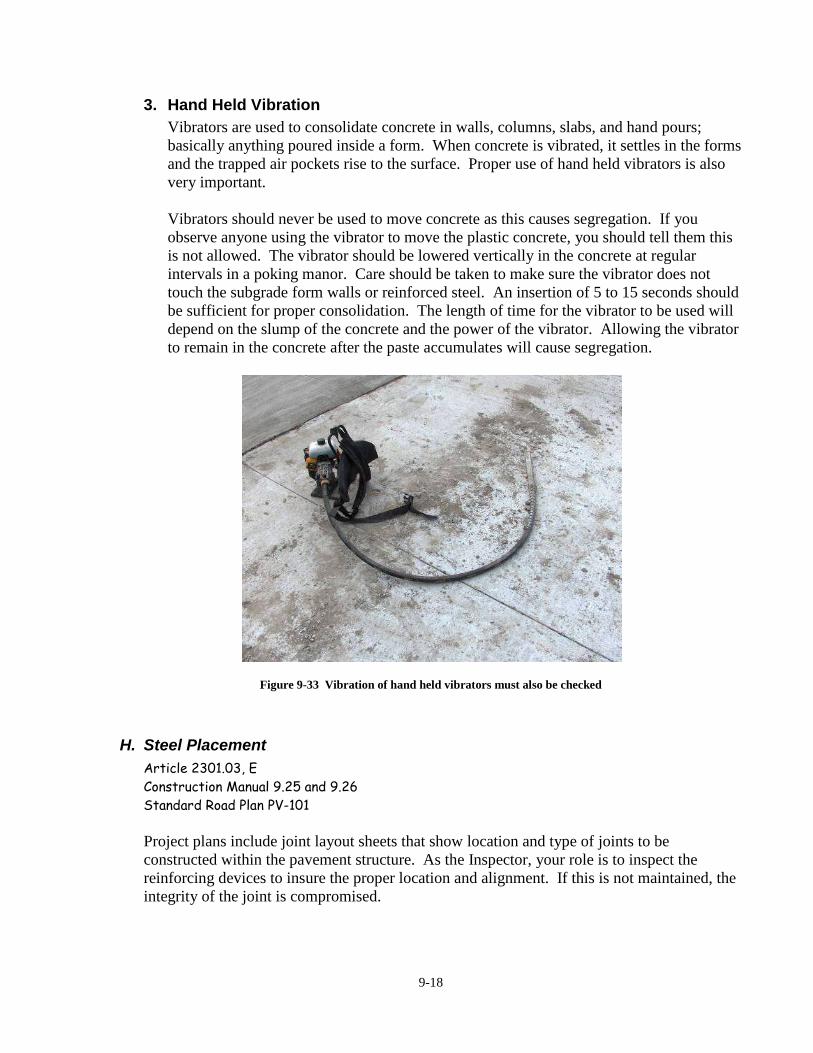
9-18
3. Hand Held Vibration
Vibrators are used to consolidate concrete in walls, columns, slabs, and hand pours;
basically anything poured inside a form. When concrete is vibrated, it settles in the forms
and the trapped air pockets rise to the surface. Proper use of hand held vibrators is also
very important.
Vibrators should never be used to move concrete as this causes segregation. If you
observe anyone using the vibrator to move the plastic concrete, you should tell them this
is not allowed. The vibrator should be lowered vertically in the concrete at regular
intervals in a poking manor. Care should be taken to make sure the vibrator does not
touch the subgrade form walls or reinforced steel. An insertion of 5 to 15 seconds should
be sufficient for proper consolidation. The length of time for the vibrator to be used will
depend on the slump of the concrete and the power of the vibrator. Allowing the vibrator
to remain in the concrete after the paste accumulates will cause segregation.
Figure 9-33 Vibration of hand held vibrators must also be checked
H. Steel Placement
Article 2301.03, E
Construction Manual 9.25 and 9.26
Standard Road Plan PV-101
Project plans include joint layout sheets that show location and type of joints to be
constructed within the pavement structure. As the Inspector, your role is to inspect the
reinforcing devices to insure the proper location and alignment. If this is not maintained, the
integrity of the joint is compromised.

9-19
1. Transverse Joints
Probably the most important of these joints is the “CD” or doweled contraction joint.
This joint utilizes the dowel as a load transfer device and is designed to allow the bar to
slide in the concrete. If it’s not properly aligned, the pavement joint will not be able to
open and close as the concrete expands and contracts due to initial shrinkage of the
concrete and temperature changes.
Figure 9-34 Paint mark to guide sawing operation
Figure 9-35 Sighting down the grade to check dowel
alignment
Check the plans for joint locations. It is important to check the placement of dowel
baskets to correspond to joint locations, particularly in multiple pass construction and
variable width placement. This is important, especially at intersections, crossovers,
intakes, or anywhere the joint has to match another feature.
Figure 9-36 Mismatch of the transverse joint and existing joints
When multiple paving passes are used, discuss joint placement prior to construction of
each pass to insure continuity of joints across stage constructed pavements. Matching

9-20
joints of crossovers and median paving with joints of each roadway seems to be a
frequent challenge.
2. Longitudinal Joints
The two main longitudinal joints are the “L” and “K” joints. “K” joints include both a
keyway and a tie bar to hold together two adjacent lanes placed at different times. There
are several ways to do this. The keyway can be slip formed in the plastic concrete with a
bent tie bar being placed in from the side. Or, the keyway is formed by a preformed
metal strip with holes in it for the bent bars. This strip is fed into the front of the paver.
For fixed form paving, the preformed metal strips are hung on the side forms with a
mechanical device. The ends of the tie bar need to be held in place by something more
than just a rock or a pile of plastic concrete.
Figure 9-37 KT joint with keyway and tie bars
“L” joints consist of deformed bars called tie bars that are placed across centerline or lane
lines when both lanes are placed at the same time. A saw cut is made above the center of
the bars after the concrete has hardened.
These tie bars can be placed either manually or mechanically.
To manually place the tie bars, a person often rides on the front of the paver or the back
of the belt placer to manually place the tie bar. Mechanical placement accomplishes the
same thing, except the person is replaced by a hydraulic ram. In either case, a timing
device is needed to obtain the correct spacing. This is usually a wheel with the correct
circumference that rides on the paver track. This activates a light to alert the person to
place the bar or it trips the hydraulic ram.
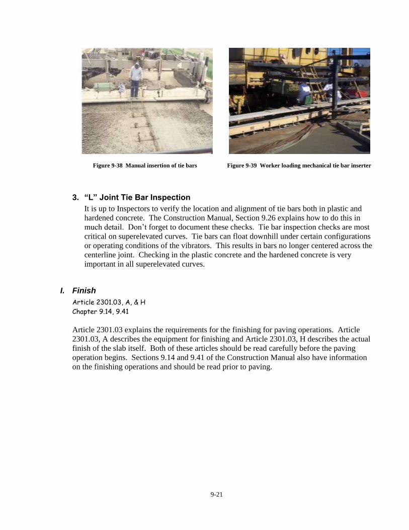
9-21
Figure 9-38 Manual insertion of tie bars
Figure 9-39 Worker loading mechanical tie bar inserter
3. “L” Joint Tie Bar Inspection
It is up to Inspectors to verify the location and alignment of tie bars both in plastic and
hardened concrete. The Construction Manual, Section 9.26 explains how to do this in
much detail. Don’t forget to document these checks. Tie bar inspection checks are most
critical on superelevated curves. Tie bars can float downhill under certain configurations
or operating conditions of the vibrators. This results in bars no longer centered across the
centerline joint. Checking in the plastic concrete and the hardened concrete is very
important in all superelevated curves.
I. Finish
Article 2301.03, A, & H
Chapter 9.14, 9.41
Article 2301.03 explains the requirements for the finishing for paving operations. Article
2301.03, A describes the equipment for finishing and Article 2301.03, H describes the actual
finish of the slab itself. Both of these articles should be read carefully before the paving
operation begins. Sections 9.14 and 9.41 of the Construction Manual also have information
on the finishing operations and should be read prior to paving.

9-22
Figure 9-40 Hand float and straight edge
The concrete workability and the paver setting are both very important factors in determining
the condition of the surface of the slab. It should be a tight surface with few bug holes in
order to get a good closed finish. If the Contractor has to use their finishing tools extensively
on the surface, this could damage the integrity of the slab. If the Inspector notices that the
finishers are working extensively to close the surface of the pavement, they should notify the
Project Manager as soon as possible.
There are times the Contractor will attempt to apply water to the surface to assist in finishing.
Article 2301.03, H prohibits additional water from being applied to the surface by spray
wand, brush, or other methods. If the Inspector notices finishers applying additional water
to the surface, they should ask the Contractor to stop this action immediately and notify the
Project Manager if they do not. Section 9.41 of the Construction Manual also covers this
topic.
Figure 9-41 Worker spraying water on burlap
Figure 9-42 Wet burlap drag
Contractors are allowed to drag wet burlap behind the paver. The wetting of the burlap
should be done sparingly. If more than a slight amount of slurry is being created by the
floats or straightedges, the contractor should be instructed to water the burlap less frequently.

9-23
Figure 9-43 Excessive slurry running over edge of slab
J. Texture
Article 2301.03, H
Construction Manual 9.42
Article 2301.03, H specifies texturing to be accomplished through either transverse or
longitudinal tining of the surface of PCC paving.
Figure 9-44 Uniform spacing for longitudinal tining
Checking the spacing of the tines on the device used to place the grooves can be done prior to
paving. Random checking of the depth of the grooves in the plastic concrete will assure the
inspector that the Contractor is placing the grooves at the proper depth. The contractor
should be urged to tine at a depth near the shallow end of the specified range. Shallow depth
creates a quieter pavement. Also, random checks after the concrete is set up will assure the

9-24
inspector that the finished product is within specification limits. If separate documentation is
not being used the Inspector should document this information in their daily diary
Figure 9-45 Transverse gouge from leaving tining rake in
contact with pavement surface
Figure 9-46 Random spacing for transverse tining
Untined Areas
Transverse Texturing
The article states that along the length of each transverse joint an area shall be
protected from surface tining to provide an untined strip, centered over the joint.
Longitudinal Texturing
Article 2301.03, H also requires an untined strip be left along the centerline for
longitudinal textured pavements. This aids in the sawing of the longitudinal joint by
not having the longitudinal tine marks interfere in the sawing operation and prevents
spalling of those joints.
Transverse or Longitudinal Texturing
In addition to the areas noted above, tining also is not required on radii, crossovers,
paved medians, shoulders, and other irregular areas per Article 2301.03, H.
K. Curing
Article 2301.03, K, & Section 4105
After finishing operations have been completed, concrete pavement must be cured. A white
pigmented liquid curing compound, meeting requirements of Section 4105 will be applied in
a fine spray to form a continuous, uniform film on the surface and vertical edges of the
pavement slab as soon as the free water has disappeared. The specifications require that the
cure should be placed no later than thirty minutes after finishing. The rate of application will
not be less than 0.067 gallon per square yard (0.3 L/m2). Hand sprayers can be used for
spraying the sides and irregular areas.

9-25
The inspector must check the lot number for each tote and verify and record that it is from an
approved lot. Check with the Office of Materials for approved lot numbers.
Figure 9-47 Verify lot numbers from cure totes
Care must be taken to insure that liquid curing materials are well agitated before and during
application. When totes or barrels are placed along the roadway ahead of the paving
operation, the curing compound may have the solids settle to the bottom. The inspector
should discuss with the contractor the agitation means and frequency that will be used to
prevent settlement.
The uniformity of cure is determined by visual inspection. The surface should look uniform
and white. If there are blotchy areas or areas of puddling, changes should be made. On
windy days, extra effort may be needed to obtain proper coverage on the up wind side of the
slab.
Figure 9-48 Curing operation
Figure 9-49 Non-uniform cure

9-26
The inspector should check the rate of application. The amount of cure used and the area
covered will have to be known. Don’t forget to include the vertical edges of the slab when
computing the area. Liquid curing compounds should dry to the touch within four hours.
After 12 hours, the cure should not track off the concrete when walked on.
Documentation should be made on the PC Concrete Item Checklist, Form M111 or E111.
L. Station Markers
The station numbers will be identified on the lath behind the construction stakes. It is the
inspector’s responsibility to make sure that the station numbers are correctly stamped into the
pavement. After the concrete has been finished and textured, use a margin trowel to smooth
a small space to stamp your station numbers. Place the numbers facing outward on the
concrete one foot away from the edge of the slab. This allows them to be easily read from
the shoulder.
Counties often face the numbers toward the center so they can be read from a car on the road
instead of the shoulder.
The numbers should be deep enough to be easily read, but not too deep, as they can hold
water when it rains.
Don’t place the number in the area of a transverse joint. Move it slightly away from the joint
location so the saw cut does not destroy the number.
Figure 9-50 Station markers stamped into slab

9-27
M. Concrete Strength
Article 2301.03, U
I.M. 316, 328, 383
The PCC Grade Inspector must keep track of the concrete strengths of each day’s paving.
1. Beams
Unless the contractor elects to use the maturity method, the concrete strength will be
determined by the beam break tests. Specification 2301.03, U requires a minimum of two
beams be cast daily, depending on the amount of concrete placed. These will be tested
for the flexural strength of the concrete at a specified age before opening the pavement
for traffic. This information is given to the Contractor by the PCC Grade Inspector so
each will know when it is permissible to drive on a section of pavement. Article 2301.03,
U regulates the times for opening pavements.
Figure 9-51 Equipment needed to cast beams
2. Maturity
The maturity method is described in I.M. 383. This is a non-destructive concrete test
method that the contractor may choose to use to determine concrete strength. When it is
used, the pavement may be opened as soon as the concrete reaches opening strength.
One of the Contractor’s people will install the Time-Temperature Factor (TTF) probe
wires. Note the station locations, as the temperature will need to be checked on a set
schedule. The inspector needs to monitor the temperature testing and maturity
determination on a periodic basis. If weather condition change very little, the gain in
TTF will normally be rather consistent and therefore monitoring may be less frequent.

9-28
Figure 9-52 Maturity probe location with hand held thermometer
N. Date of Placement
Construction Manual 9.46
The date (MM-DD-YY) will always be stamped into the concrete at the beginning and at the
end of every day’s placement, near each header. As with the station numbers a small space
should be smoothed with a margin trowel on the finished and textured concrete. Then place
the numbered stamps onto the concrete 1-foot away from the edge of the slab and near the
joint, facing outward, so that it can be read from the shoulder. The purpose is to be able to
easily identify each day’s work. You want the numbers deep enough to read easily but not
too deep!
Figure 9-53 Date stamped into the slab at a header

9-29
O. Monitor Contractor’s Haul Road
Section 1107
Construction Manual 2.12
A haul road is the designated road on which the Contractor is to haul material either to the
grade from the plant or to the plant from the material suppliers. The Contractor may use a
public road between the plant or supplier and the grade or a road within the limits of the
project. If the Contractor uses a public road, this road must be considered as a haul road and
may require agreements with local jurisdictions. The haul road system must be reviewed and
approved by the Project Engineer before the operations associated with the paving begin.
Figure 9-54 Truck fire blocked haul road
The material coming from the plant site may come on a different road than the material for
the longitudinal subdrain or shoulder work. Their roads must be reviewed carefully before
they are designated as a haul road. The structure of the road, weight restrictions of
structures, traffic signing, safety, and a number of other aspects should all be reviewed.
There will be occasions when the haul road may not be the most direct route for the
Contractor to take and they may want to use a different road. It is the responsibility of both
the Grade Inspector and the Plant Inspector to ensure the Contractor is using the designated
haul roads. If the Contractor deviates from the designated haul roads, the entity, such as the
County or the City, which owns these roads, may, and probably will ask for damage
considerations. That is why an agreement is reached with the affected entity of the
designated haul road in advance of its use.

9-30
Section 1107 “Safety, Health, Pollution, and Sanitation” and the Construction Manual
Chapter 2.12 explains when and how dust control should be maintained. This can be a little
confusing and should also be reviewed with the Project Manager before operations begin.
Haul roads are created on the project site for the delivery of concrete to the paver. These
normally are alongside the new slab, just outside the stringline. Because they are only used
for a short time, they normally are not stabilized and can become either soft during wet
conditions or dusty during dry conditions. These roads are the responsibility of the
contractor, but in the case of dust, they can become an issue for the inspector because of
safety considerations.
Figure 9-55 Wetting the haul road for dust control
During wet periods, the roads can become rutted and, because of the soft conditions, care
must be taken not to have the stringline stakes be “pumped” or move up or down and change
the elevation of the string which can create bumps in the slab.
Figure 9-56 Muddy, rutted haul road
Figure 9-57 Motor patrol grading haul road

9-31
P. Documentation
The Inspector must document the checks they perform or witness and any violations of the
specifications and corrective actions taken. The documentation could include, but may not
be limited to, the date, location (NBL, SBL, station, centerline offset), who was notified, the
corrective action needed to be taken, and when such action was taken.
Individual check sheets could be made up for each test or check the Inspector performs. This
may seem like extra paper work, but if the Inspector were asked what the depth of the
pavement was on a certain date at a certain location, they would be able to check the
appropriate worksheet and provide this information. This would be easier then reading
through the diary entries or a worksheet where all of this information has been compiled.
When a separate form is not used, the Inspector should document the violations of the
specifications, when the Contractor was notified, and corrective actions taken, in their daily
diary.
Q. Monitor Contractor’s Housekeeping
The role of the Inspector on the housecleaning of the Contractor is actually quite limited. If
the Contractor is not posing a health or safety threat, there is little an Inspector can do. The
Inspector can suggest to the Contractor how the traveling public may perceive an unsightly
work site, but again, if the health and safety of someone is not threatened, the Inspector has
little authority to make them clean it up.
The Inspector can monitor open burning. The Contractor is not allowed to burn anything that
is considered trade waste. Trade waste is described as any refuse resulting from the
prosecution of any trade. This would include the burlap and plastic used by the Contractor to
cover the pavement.
The Inspector should monitor the sites that the Contractor is using to assure that no toxic
substances are being allowed to enter the ground. For a PCC Inspector, this could include,
but is not limited to, curing compound or oil from machines.
If the Inspector sees something they are uncomfortable with or unsure about, they should
inform the Project Manager as soon as possible.

9-32
Figure 9-58 Communicate with the contractor when questionable activities are observed
R. Non-Compliance Notices
Construction Manual 2.53
Construction Manual Appendix 2-34
When the Inspector encounters work that is outside of the specifications, it is considered to
be non-complying. The Inspector should notify the Project Manager as soon as possible.
The Project Manager will then issue a Non-Compliance Notice to the Prime Contractor. The
notice will inform the Contractor which article has been violated, the specification limits, and
the actual value. A price adjustment, if any, will be described in the remarks area, and the
corrective action will be stated, if applicable. This form number is 830245. No matter how
minute the violation is, a notice should be issued so that there is a written record of the
Contractor being notified.

9-33
Figure 9-59 Noncompliance form 830245
Additional guidance and discussion on price adjustments can be found in Construction Manual
2.53 and Construction Manual Appendix 2-34.

9-34

C
HA
PT
ER
10
PO
ST
CH
EC
KS

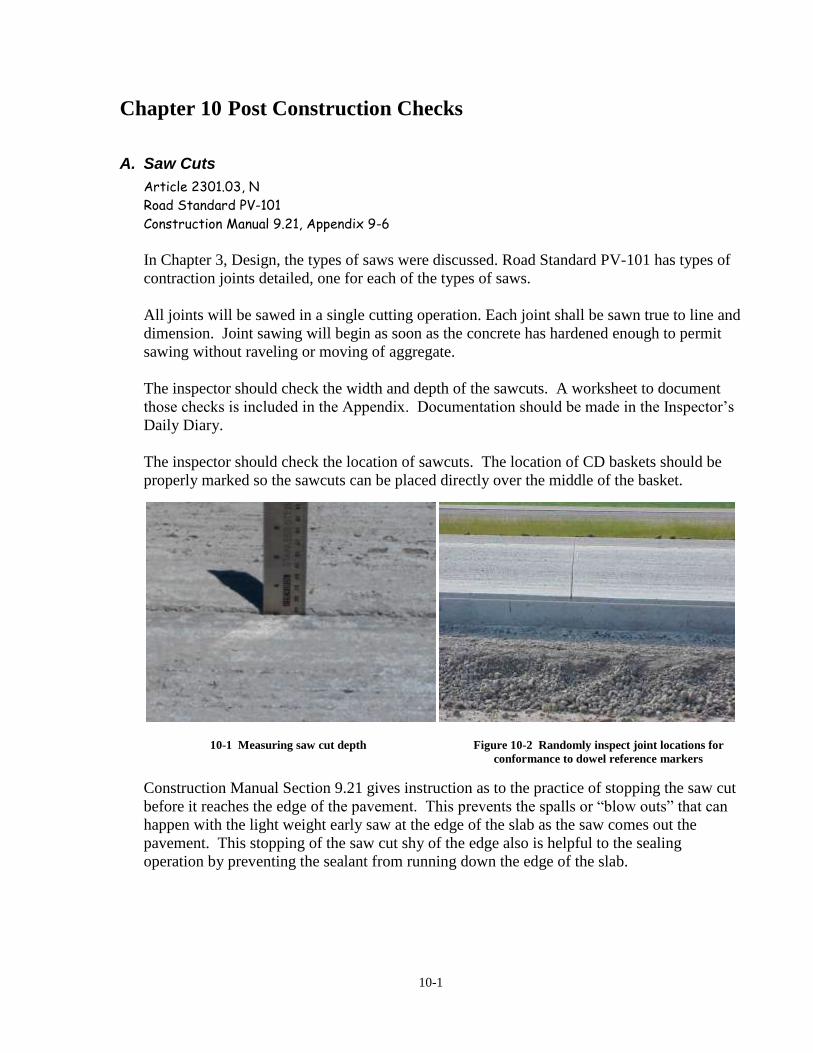
10-1
Chapter 10 Post Construction Checks
A. Saw Cuts
Article 2301.03, N
Road Standard PV-101
Construction Manual 9.21, Appendix 9-6
In Chapter 3, Design, the types of saws were discussed. Road Standard PV-101 has types of
contraction joints detailed, one for each of the types of saws.
All joints will be sawed in a single cutting operation. Each joint shall be sawn true to line and
dimension. Joint sawing will begin as soon as the concrete has hardened enough to permit
sawing without raveling or moving of aggregate.
The inspector should check the width and depth of the sawcuts. A worksheet to document
those checks is included in the Appendix. Documentation should be made in the Inspector’s
Daily Diary.
The inspector should check the location of sawcuts. The location of CD baskets should be
properly marked so the sawcuts can be placed directly over the middle of the basket.
10-1 Measuring saw cut depth Figure 10-2 Randomly inspect joint locations for
conformance to dowel reference markers
Construction Manual Section 9.21 gives instruction as to the practice of stopping the saw cut
before it reaches the edge of the pavement. This prevents the spalls or “blow outs” that can
happen with the light weight early saw at the edge of the slab as the saw comes out the
pavement. This stopping of the saw cut shy of the edge also is helpful to the sealing
operation by preventing the sealant from running down the edge of the slab.

10-2
Figure 10-3 Pull up of sawcut before edge of slab
Figure 10-4 Blowout at edge of slab
1. Early entry saws
When the early entry saw is used, the start of the sawing window is much earlier than
when the larger conventional saws are used. Often, sawing can begin within about 3
hours of placement of the concrete, depending on weather conditions and concrete mix
temperature.
Figure 10-5 Early entry saws
The early entry saw offers a number of advantages compared to conventional saws.
There is very little dust because the saw cut is made when the concrete is very green and
there is a lot of moisture still in the sawing residue. The sawing residue is then left in a
small pile next to the joint. Also, this type of saw is smaller than conventional saws so it

10-3
is less powerful, but much quieter. This is particularly helpful in urban environments
where noise is a concern.
Figure 10-6 Residue from early entry sawing
2. Conventional saws
With conventional saws, the sawing normally doesn’t begin until eight to twelve hours
after placement. The sawing is normally done with diamond blades and can be done as a
dry process or wet sawing may be used.
Figure 10-7 Conventional dry saw on longitudinal joint

10-4
Note that the specifications do not allow the early entry saw to be used to cut longitudinal
joints unless it can cut the joint to the conventional depth and specified width. This is
intended for rural mainline paving but may not be true for overlays with small panel
design.
Joints must be sawed before uncontrolled cracking takes place. Sawing operations will be
continuous, regardless of weather or daylight conditions. Sawing of a joint will be
discontinued if a crack develops ahead of the saw. In this case a joint will be formed with a
crack saw along the line of the crack and the joint will be cleaned and sealed. When random
transverse cracks occur, Article 2301.03, N requires that the pavement be repaired.
Appendix 9-6 in the Construction Manual provides guidance for repair of random cracking.
The inspector needs to work with the contractor to insure that joints in irregular areas are
sawn properly. Project plans will show the location of these joints. Be careful not to have
saw joints intersect at a “T” corner. Often these will lead to a random crack.
Figure 10-8 Late sawing crack
Figure 10-9 Poor jointing resulted in crack
B. Sealing Joints
Article 2301.03, P & Section 4136
Road Standard PV-101
Construction Manual 9.22 and 9.23
Unless otherwise provided, before any portion of the pavement is opened to the Contractor’s
forces or to general traffic, expansion joints and transverse joints will be sealed. The
exception to this would be on overlays where the pavement is sawn into panels smaller than a
lane width. See Section 2310 for specific instructions.

10-5
The joint opening will be sawed or prepared to the designated dimensions and cleaned. Joint
sealer, meeting requirements of Section 4136 will be used to seal sawed joints in PCC
pavement, shoulders, medians, crossovers, and side road pavement unless otherwise
specified.
Within three hours after the joint has been wet sawed, the residue will be flushed away with a
high-pressure water blast. Within three hours after the joint has been dry sawed, the residue
will be blown from the joint. Sand cleaning will not be required for joints narrower than 3/8
inch (10 mm). If they are that width or wider, sand cleaning will be required using the proper
equipment.
Immediately prior to the installation of the backer rod and sealant, the joint will be cleaned
with an air blast. The backer rod will be of the proper size and type and will be installed dry,
with a suitable tool. Joints sawn with early entry saws do not require a backer rod.
Figure 10-10 Air blast of joint prior to sealing
Figure 10-11 Installing backer rod
Joint sealer will be prepared and installed in the joint to the proper level. To insure that the
transverse joint is filled uniformly across the entire width of pavement, the contractor should
raise the saw immediately before the edge of the pavement, thereby not continuing the saw
cut opening through the edge of the pavement and preventing sealer material from running
out of the joint. After sealing, excess sealer will be removed from the pavement surface.

10-6
Figure 10-12 Installing hot pour sealant
Joint sealer can be placed only when the pavement and surrounding air temperature are 40
degrees F (4 degrees C) or higher. Sealing will be done only when the joint surfaces appear
dry by visual inspection.
Figure 10-13 Joint sealant both overfilled and underfilled
The inspector should check that all joints are cleaned sufficiently and the backer rod is
approved and installed properly. An approved joint sealer must be used and installed in the
joint at the proper elevation. A worksheet to document these checks is included in the
Appendix. Documentation should be made in the Inspector’s Daily Diary.

10-7
Figure 10-14 Joint check worksheet
C. Texture
Article 2301.03, H
Chapter 9.43
Once the pavement has hardened, checks of the depth can be made to determine compliance
with Article 2301.03, H. Chapter 9.43 describes the procedure required to check the depth of
the texture. A worksheet to document these checks is included in the Appendix.
Figure 10-15 Check tining depth with a tire tread checker

10-8
The depth of the texture is important. The grooves are constructed to break the plain surface
and thereby prevent hydroplaning. But, the grooves can create a noise problem. In order to
minimize the noise from the pavement surface, the tine depths shall be as shallow as possible
within the specification limits. This will insure safety but minimize any objectionable noise.
Figure 10-16 Tining depth check Form E140
Figure 10-17 Texture check worksheet
D. Smoothness
Sections 2316 & 2317
I.M. 341
The requirements for pavement smoothness are outlined in Sections 2316 & 2317. A
California type profilograph, commonly referred to as a profilometer, or an inertial profiler
may be used to evaluate smoothness. The profilometer produces a profilograph, commonly
referred to as a profile trace or simply a trace. The contractor performs the test and supplies
the inspectors with the results. The method of testing using the profilograph is outlined in
I.M. 341.

10-9
Figure 10-18 California profilograph
Figure 10-19 Inertial profiler
The inspector shall review the traces, not only to look for errors in the reduction but also to
look for possible gaps in the traces where smoothness results for part of the pavement may be
missing
The agency will check the traces by rerunning at least ten percent of the area tested. See IM
204 Appendix E.
The PCC Grade Inspector may be the person receiving the traces from the Contractor. As
stated in the specification book, each segment should be evaluated within 48 hours after
placement. At the start of paving, the index should be available by the end of the day
following paving until there are three consecutive days where the index for all segments
would result in 100% or better payment. After three consecutive days, they are to be made
available within 48 hours after each day’s run. If subsequent days result in less than 100%
payment the contractor is to immediately notify the Engineer and modify paving methods to
achieve 100% or better pay. The inspector needs to be familiar with this specification so they
know when to expect the traces and indices from the contractor.
When corrective work is required, the contractor should use diamond grinding equipment
meeting the requirements of Section 2532.

10-10
Figure 10-20 Grinding to improve smoothness
E. Strength
Article 2301.03, U
I.M. 204, 316, 328, 383
For concrete pavement, strength is tested for two purposes. One is to determine the strength
for opening the pavement to traffic. The other is to determine the 28-day strength of the
concrete. This is for information to those who perform the pavement design and is not a
contract requirement as is often the case with other types of concrete construction
Casting of the beams and curing is critical to the accuracy of the test results. IM 328 defines
this procedure, and everyone involved in this process must be familiar with the procedures.
Great care needs to be taken throughout the process and the inspector needs to be very
diligent to insure that proper methods are followed.
1. Beams
I.M. 328 explains how to make a flexural strength field specimen, commonly referred to
as a beam. It is necessary to know how to properly make a beam because this may
determine how soon the Contractor can utilize a section of pavement. A poorly
constructed or cured beam will not give an accurate determination of the strength of the
pavement.
The Grade Inspector will need to transport the beams to the plant site, usually the
following day. Care should be taken when transporting beams so that they are not
damaged on the way to the plant site. Any unnecessary stress, such as bouncing around
in the back of a pickup, can lead to small micocracks within the beam. These beams may
be less than twenty-four hours old and can easily be damaged.

10-11
Figure 10-21 Take care in casting, curing, and
transporting beams
Figure 10-22 If maturity is used, beam strength is
tested by the agency for information only
The curing and testing of the beams is the responsibility of the Certified Plant Inspector.
This includes the removing of the beams from the molds, cleaning and reassembling of
the molds, and returning the molds to the grade. The Grade Inspector may be able to pick
up the empty beam molds when they transport the beams to the plant site.
The testing of the beams is the responsibility of the Certified Plant Inspector, but the
method of testing is good information for the Grade Inspector to know. I.M. 316 explains
the testing procedure
Article 2301.03, U specifies the time for opening pavements. When the Contractor uses
beam breaks to determine strength, both an age and strength requirement must be met
before the pavement is opened.
Figure 10-23 PC Concrete Beam Record Form E114

10-12
2. Maturity
Article 2301.03, U allows the contractor to use the maturity method to determine the
opening strength. When the contractor chooses this option, only the strength of the
concrete is used to determine pavement opening. No time restriction is imposed. The
contractor must perform the maturity testing but the inspector will monitor the process.
IM 383 describes the process.
NOTE: When maturity is used, the agency is still responsible to open the pavement to
traffic. The contractor’s maturity test provides that information, but it is the
agency that will determine that strength has been reached and then will give the
contractor permission to use the new pavement.
The maturity process involves casting 12 beams at the plant site and developing a
strength/maturity curve. Then temperature probes are placed in the slab, from which the
temperature is monitored and the strength determined.
Figure 10-24 Casting maturity beams at the plant site
At least two probes are placed in a day’s paving. If shadows from trees or other
obstructions are present which make the solar energy different in different parts of the
day’s pavement placement, more probes may be necessary.
The probes need to be clearly marked so as to insure that they are not disturbed. The
sawing operation sometimes is performed at night and it is easy to have them accidentally
pulled out if they are not clearly marked out.
Commonly checks of the maturity probes are made in the morning when work begins and
again in the late afternoon before work is stopped for the day. The inspector should
accompany the contractor’s person when checking the maturity readings often enough to

10-13
be satisfied that readings are appropriate. If the weather is fairly consistent, the opening
time will remain about the same from day to day. Big changes in temperature during the
first two days after paving will have a significant effect on the development of the
strength of the concrete.
Figure 10-25 Maturity probe in slab
Figure 10-26 Checking temperature with hand held
thermometer
Figure 10-27 Maturity field data form
Figure 10-28 Maturity Record Form E141

10-14
F. Steel Placement
Article 2301.03, E
Road Standard PV-101
Construction Manual 9.26 & 9.27
The centerline joints will have tie steel placed by: mechanical insertion, hand methods during
construction, or supported by chairs prior to paving. Chapter 9.27 outlines the procedure and
requirement for checking the placement of this steel, both in the plastic concrete and in the
hardened slab. This is important to assure that the proper placement is being accomplished.
The bars need to be centered across the longitudinal joint. They need to be reasonably level
and perpendicular to the centerline, although the tolerances are not as precise as for dowels
since these bars are deformed and the pavement does not slide on them. Chapter 9.27 also
discusses the number of bars required per panel.
Care by the Contractor and timely inspection should eliminate problems during construction.
If a problem does arise and it is not detected until the concrete has hardened, corrective
repairs may be required.
Figure 10-29 Marking tie bar locations Figure 10-30 Out of tolerance/missing tie bars
Two common methods that can be used to repair misplaced or omitted steel are the slot
method for both transverse and longitudinal joints and the cross-stitch method for
longitudinal joints.
The slot method simply involves cutting a slot approximately half the depth of the pavement,
placing a bar in the slot and filling the slot with a grout or epoxy material.
A cross-stitching repair procedure is often used for tie bar repair. It involves drilling a hole
on a very flat angle such that it crosses the joint or crack and does not protrude out the
bottom of the slab. Epoxy is injected into the hole, and a bar is then inserted.

10-15
Figure 10-31 Cross-stitch repair of random cracks
Figure 10-32 Cross-stitch repair of missing tie steel
G. Coring
Articles 2301.04 and 2301.05
I.M. 346, 347
Cores shall be taken from PCC pavement to determine pavement thickness, the thickness
index for each section, and the amount of payment the Contractor will receive. The Agency
will identify the limits of each section and the random location of each core. The Inspector
will witness core drilling, take immediate possession of the cores, and determine and record
core lengths. I.M. 346 outlines the procedure that is to be followed in order to determine the
core locations.
1. Locating Cores
The Inspector will first assign all cores a number. Core numbers should be consistent
with the District number system.
The locations are then marked on the road. These should be placed as accurately as
possible to insure the proper location. A significant amount of money can be riding on
the core results.
The inspector and contractor should check to insure there is not a dowel bar or a traffic
detector loop in the pavement in that location. If so, the inspector shall approve the
moving of the core location slightly in order to miss the obstruction.
The Inspector will also go along with the Contractor while they are cutting the cores.
This is to verify that they cut them at the right locations and are marked with the proper
numbers. Also, check to see if there are any deficient cores.

10-16
The Inspector will take possession of the cores, measure them, and make arrangements to
deliver them to the District Lab.
Figure 10-33 Coring for thickness
2. Deficient Areas
A core is deficient when it measures 1 in. (25 mm) or more short of plan length. Extra
cores will be taken, each way of the original location, at 60 ft (18 m) intervals until a core
of the proper length is found. The deficient area will be removed and replaced by the
Contractor. The extra cores are not used in the Thickness Index calculations.
3. Length Evaluation
To measure the cores, a calipering device is used. This is better known as “9-pointing the
core” because the core is measured in nine places. I.M. 347 explains how to do the
measuring in detail.
I.M. 346 specifies how to calculate the Thickness Index by hand using a calculator with
standard deviation formula (n-1). This may be okay for small projects, but not for large,
more complex ones. There is a computer program for these calculations that is available
from the Materials Office. It is recommended that it be used for all projects.
Compare the Thickness Index with the Payment Schedule in Article 2301.05. This will
give the Percent Payment. Payment will be a percentage of the contract Unit Price.

10-17
Figure 10-34 Nine-point core length measuring device
4. Reporting
The computer program produces a report that will accompany the cores when delivered
to the District Materials Lab. Distribution of this report will be made after the
Independent Assurance measurements are added.
5. MIT Scan T2
An alternative method to measure pavement thickness is now becoming commonplace on
many projects. It utilizes Magnetic Imaging Tomography (MIT) to scan steel plates
placed upon the base material prior to paving to determine the pavement thickness. See
the current developmental specification for requirements.
Figure 10-35 Non-destructive thickness measuring device

10-18

C
HA
PT
ER
11
AS
SO
C. C
ON
ST
. AC
TIV
ITIE
S


11-1
Chapter 11 Associated Construction Activities
Once the pavement is placed, there are other activities that must be accomplished before the
roadway can be opened to traffic. These are a part of the paving contract and therefore are a part
of the project and the inspection duties. The following sections describe the earth shoulder
construction, longitudinal subdrain construction, and the granular shoulder construction. This is
the order that they are normally accomplished.
A. Earth Shoulder Construction.
Section 2123,
Construction of earth shoulders adjacent to new PCC pavements should begin shortly after
pavement has reached maturity and has been opened to the contractor's vehicles.
Specification 2123.03, B states that “Adequate organization and equipment shall be assigned
to this work so that the major portion of shouldering work may be completed within six days
after the pavement or base is released by the engineer to the contractor for shoulder work.
Active enforcement of this specification encourages timely completion of project and helps
shed water to the foreslope and ditch area instead of trapping it in the subgrade trench.
Completion of earth shoulder work prior to subdrain operations ensures direct contact
between the porous trench and bottom of granular shoulder. Contract documents will show
typical details and quantities and contract items to be used for this work.
Class 10 or specified material is hauled in dump trucks or scrapers to desired locations.
Material is spread and leveled with a dozer or motor patrol and compacted as per
specifications. Then shoulder areas are trimmed to desired elevation by a motor patrol. The
shoulder area is now ready for subdrain operations.
Figure 11-1 Depositing and spreading earth shoulder
material
Figure 11-2 Compacting earth shoulder material

11-2
A common problem that both the contractor and the inspector must watch closely is the
difficulty in blading and compacting the shoulder material immediately next to the edge of
the pavement without damaging the edge. The motor patrol and roller can bump into the
edge of the slab and chip off the top edge of the concrete. The inspector needs to watch for
this type of damage and have the contractor change procedures if it occurs frequently.
Figure 11-3 Shoulder after compaction and prior to final
finishing
Figure 11-4 Chipped pavement edge
B. Longitudinal Subdrains
Sections 2502, 4143, 4141, 4131, 4109
Road Standard RF-19C, & RF-19E
The construction of shoulder subdrains will consist of furnishing and installing subdrain of
the size shown in the contract documents. The subdrain will be installed at the locations and
to the grades and elevations shown in the contract documents.
Pipe for subdrains will be of the size and type shown in the contract documents and will meet
requirements of Section 4143. Perforated corrugated polyethylene tubing and fittings will be
used. The tubing will be marked with AASHTO M252. The tubing will be perforated with
slots. Circular perforations will not be approved.
As per Standard Road Plan, RF-19E, subdrain outlets will be 6 inches (150 mm) corrugated
metal pipe meeting requirements of Section 4141 or 4 inches (100 mm) corrugated walled PE
or PVC pipe with an appropriate coupler.
1. Excavation
The trench for the subdrain is constructed adjacent to the edge of the pavement. It
normally is dug with an excavation machine that creates a trench of the proper width and
depth.
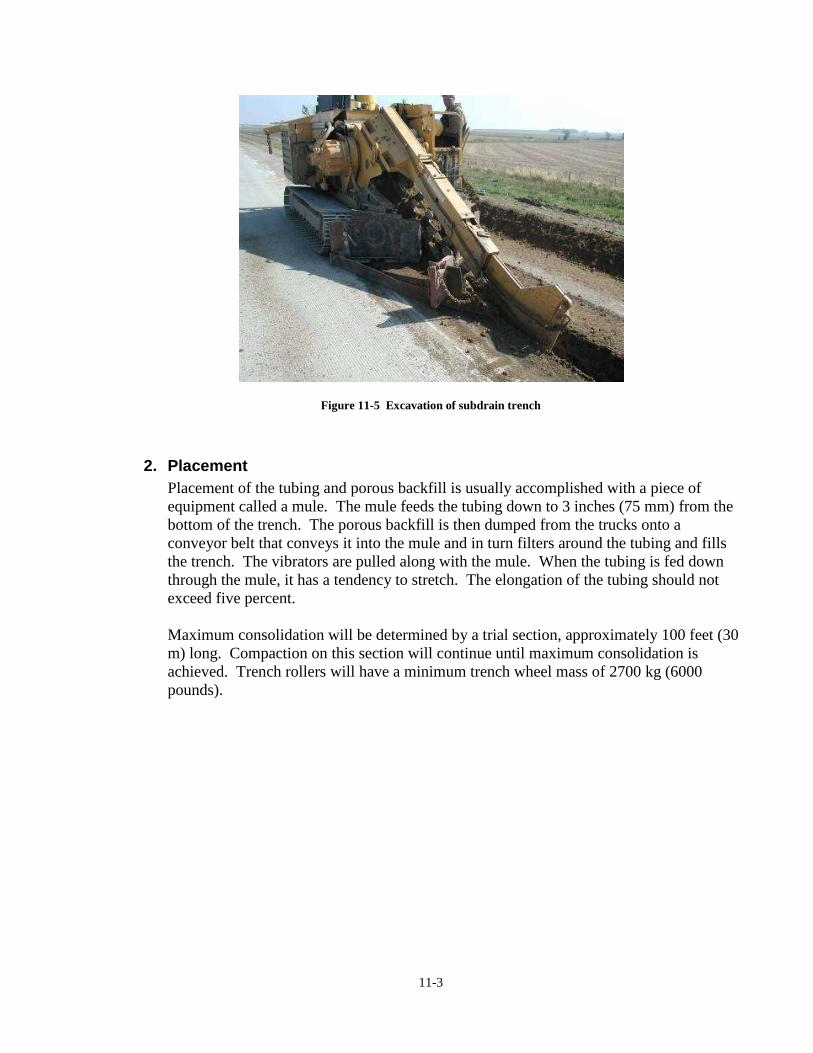
11-3
Figure 11-5 Excavation of subdrain trench
2. Placement
Placement of the tubing and porous backfill is usually accomplished with a piece of
equipment called a mule. The mule feeds the tubing down to 3 inches (75 mm) from the
bottom of the trench. The porous backfill is then dumped from the trucks onto a
conveyor belt that conveys it into the mule and in turn filters around the tubing and fills
the trench. The vibrators are pulled along with the mule. When the tubing is fed down
through the mule, it has a tendency to stretch. The elongation of the tubing should not
exceed five percent.
Maximum consolidation will be determined by a trial section, approximately 100 feet (30
m) long. Compaction on this section will continue until maximum consolidation is
achieved. Trench rollers will have a minimum trench wheel mass of 2700 kg (6000
pounds).
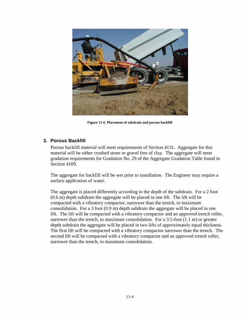
11-4
Figure 11-6 Placement of subdrain and porous backfill
3. Porous Backfill
Porous backfill material will meet requirements of Section 4131. Aggregate for this
material will be either crushed stone or gravel free of clay. The aggregate will meet
gradation requirements for Gradation No. 29 of the Aggregate Gradation Table found in
Section 4109.
The aggregate for backfill will be wet prior to installation. The Engineer may require a
surface application of water.
The aggregate is placed differently according to the depth of the subdrain. For a 2 foot
(0.6 m) depth subdrain the aggregate will be placed in one lift. The lift will be
compacted with a vibratory compactor, narrower than the trench, to maximum
consolidation. For a 3 foot (0.9 m) depth subdrain the aggregate will be placed in one
lift. The lift will be compacted with a vibratory compactor and an approved trench roller,
narrower than the trench, to maximum consolidation. For a 3.5-foot (1.1 m) or greater
depth subdrain the aggregate will be placed in two lifts of approximately equal thickness.
The first lift will be compacted with a vibratory compactor narrower than the trench. The
second lift will be compacted with a vibratory compactor and an approved trench roller,
narrower than the trench, to maximum consolidation.
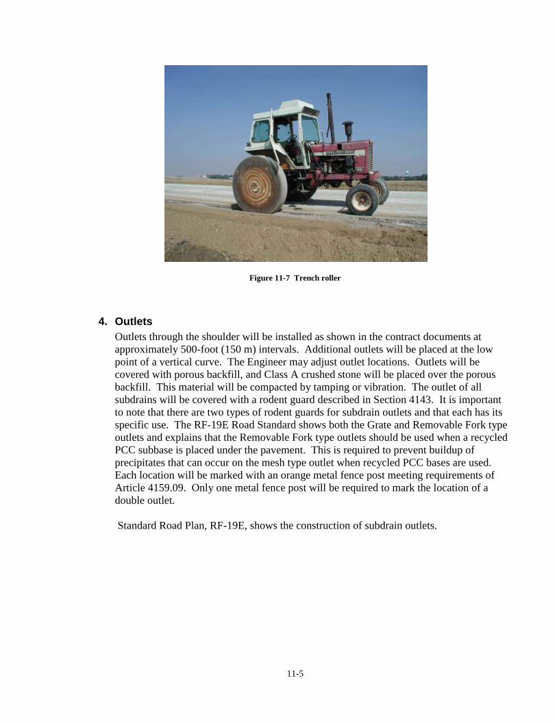
11-5
Figure 11-7 Trench roller
4. Outlets
Outlets through the shoulder will be installed as shown in the contract documents at
approximately 500-foot (150 m) intervals. Additional outlets will be placed at the low
point of a vertical curve. The Engineer may adjust outlet locations. Outlets will be
covered with porous backfill, and Class A crushed stone will be placed over the porous
backfill. This material will be compacted by tamping or vibration. The outlet of all
subdrains will be covered with a rodent guard described in Section 4143. It is important
to note that there are two types of rodent guards for subdrain outlets and that each has its
specific use. The RF-19E Road Standard shows both the Grate and Removable Fork type
outlets and explains that the Removable Fork type outlets should be used when a recycled
PCC subbase is placed under the pavement. This is required to prevent buildup of
precipitates that can occur on the mesh type outlet when recycled PCC bases are used.
Each location will be marked with an orange metal fence post meeting requirements of
Article 4159.09. Only one metal fence post will be required to mark the location of a
double outlet.
Standard Road Plan, RF-19E, shows the construction of subdrain outlets.

11-6
Figure 11-8 Outlet placed to toe of foreslope
Figure 11-9 Outlets on patio blocks and marked by
metal post
5. Restoring the shoulder
Shoulder subdrain work will include restoration of the shoulder and foreslope area.
Unpaved shoulders will be finished with a minimum depth of 4 inches (100 mm) of
granular shoulder material and compacted. Shoulders paved with HMA will be finished
with a minimum depth of 6 inches (150 mm) of HMA base or better. They shall be
compacted in an initial 4-inch (100-mm) lift and a final lift, which restores the surface
flush with not more than 1/4 inch (5 mm), above the adjacent pavement surface. Each lift
will be thoroughly compacted with a minimum of three passes with a single vehicle tire
loaded to 6000 pounds (2700 kg) and no wider than the trench, or by equivalent
compaction with an approved trench roller.
When subdrains are constructed on existing roads, and when removal of the excavated
material is required, the material will be loaded directly into the transporting vehicle. If
the contract documents do not designate an area to place this material, the Contractor will
find his own disposal area.
Figure 11-10 Outlet covered with granular material
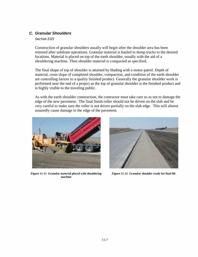
11-7
C. Granular Shoulders
Section 2121
Construction of granular shoulders usually will begin after the shoulder area has been
restored after subdrain operations. Granular material is hauled in dump trucks to the desired
locations. Material is placed on top of the earth shoulder, usually with the aid of a
shouldering machine. Then shoulder material is compacted as specified.
The final shape of top of shoulder is attained by blading with a motor patrol. Depth of
material, cross slope of completed shoulder, compaction, and condition of the earth shoulder
are controlling factors to a quality finished product. Generally the granular shoulder work is
performed near the end of a project as the top of granular shoulder is the finished product and
is highly visible to the traveling public.
As with the earth shoulder construction, the contractor must take care so as not to damage the
edge of the new pavement. The final finish roller should not be driven on the slab and be
very careful to make sure the roller is not driven partially on the slab edge. This will almost
assuredly cause damage to the edge of the pavement.
Figure 11-11 Granular material placed with shouldering
machine
Figure 11-12 Granular shoulder ready for final lift

11-8
Figure 11-13 Final shoulder finish with compaction and
brooming of slab
Figure 11-14 Roller partially on pavement causing edge
damage
D. Paved Shoulders
Section 2122
Often, on more heavily travelled roadways such as the Interstate system or four-lane divided
roadways, fully or partially paved shoulders are placed. There are many benefits realized by
placing paved shoulders on higher volume roadways. Paved shoulders improve safety by
eliminating edge rutting adjacent to the travelled way as well as providing a paved surface to
regain control of an errant vehicle that leaves the roadway. Often rumble strips are placed in
paved shoulders. This helps to reduce frequency of run off the road crashes.
Paved shoulders can be either Hot Mixed Asphalt (HMA) or PCC. In recent years,
contractors have been given the option of bidding one or the other. This is called paved
shoulder alternates.
Construction of paved shoulders begins after subdrain placement and shoulder subgrade
restoration are complete. Typically six inches of Special Backfill is placed under paved
shoulders as a support layer for the pavement. Paved shoulder thicknesses range from six to
eight inches for HMA and seven inches for PCC.
Many of the same inspection procedures should be followed for paved shoulders as are for
mainline pavement. Subgrade elevation and cross slope should be checked prior to Special
Backfill placement as well as checking the top of Special Backfill prior to placement of the
paved shoulder material. For PCC shoulders, a Class A or Class C concrete mixture is
allowed. The contractor may also elect to use the same concrete mixture as was used for the
mainline paving. For the most part, all of the requirements in Section 2301 that applied to
the mainline pavement, are also applicable when placing paved PCC shoulders.
Similar to granular shoulder placement, damage to the edge of the PCC pavement is a
concern when placing HMA shoulders. Carelessness on the part of the contractor can create
a significant amount of damage and result in serious price adjustment and/or costly repairs.
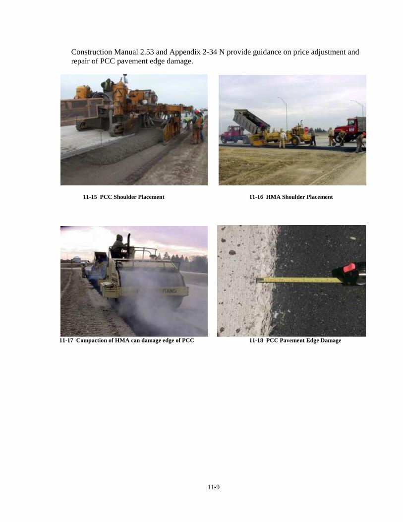
11-9
Construction Manual 2.53 and Appendix 2-34 N provide guidance on price adjustment and
repair of PCC pavement edge damage.
11-15 PCC Shoulder Placement 11-16 HMA Shoulder Placement
11-17 Compaction of HMA can damage edge of PCC 11-18 PCC Pavement Edge Damage

11-10

CH
AP
TE
R 12
UR
BA
N P
AV
ING


12-1
Chapter 12 Urban Paving
Paving in an urban situation offers unique challenges not always encountered on typical
paving projects. Utilities, staging and accesses are much more critical issues to the agency,
contractors, property owners, and the traveling public.
Figure 12-1 Utility conflicts can cause major delays
Prior to starting an urban paving project, check the information from the right of way
contract for each property owner and compare any specific request from the owners to plan
information, particularly with regard to entrances. Also become familiar with the locations of
intakes, manholes and sidewalks, as they will all require some type of special shaping.
Urban projects will usually have a base consisting of special backfill or modified subbase.
This allows the contractor to utilize the base as a haul route for concrete delivery. This haul
route in turn creates its own set of problems as the inspector must monitor the condition of
the base to avoid rutting. Dowel bar placement is done just prior to the paving operation.
Placement of subdrains will usually occur prior to paving, as drains are underneath the slab in
most urban situations.
In addition to the numerous physical limitations on projects, there are also the environmental
restrictions that come into play. Most Cities restrict the disposal of concrete washout
material from ready mix trucks. It is important that washout from these vehicles be disposed
of properly.

12-2
Figure 12-2 Delivery of ready mix from closed lane Figure 12-3 Containment of concrete washout
A. Boxouts
On urban paving projects you will become very familiar with boxouts and gaps while
placing pavement. Boxouts will generally occur at intake/manhole locations, side street
connections and at pavement width change locations. Also temporary access for property
owners can result in gaps in pavement. The contractor will usually form a boxout by
staking steel forms in place. Then rock is normally placed in the boxout to prevent the
intended gap from filling with concrete as the paver passes by. It is important that the
forms be checked for accuracy of placement and checked for stability, as the paving
machine will exert a lot of force on forms as it passes by.
Figure 12-4 Boxouts in multilane paving

12-3
After the paving machine passes by, the contractor should dig concrete and rock out of
the boxout to insure that dowel bars and forms are in the proper locations. Later in the
project the side road will be placed or a subcontractor will fill in manhole boxouts.
Jointing around boxouts is very important. Irregular shapes often require additional
joints in order to prevent cracks from forming. Sometimes the pavement jointing must be
modified in order to accommodate the jointing required by the boxout.
Figure 12-5 Boxout for utility access
Figure 12-6 Crack resulting from poor jointing
B. Curbs
Urban projects will usually always have curb and gutter. When machine paving, the
contractor will have a curb-shaped template attached to paving machine pan to form the
curb. This typical pavement section requires additional inspection of gutter flowline
elevations to prevent problems of water ponding instead of flowing to intakes and
manholes. Also, driveway and sidewalk curb cuts will require modification of the normal
curb section by hand finishing. Median and stop sign islands will require special shaping
of the curb section by hand finishing as well. Close attention should be given to the plan
details for location and type of joints to insure that the contract requirements are being
met.

12-4
Figure 12-7 Hand placement of curb
C. Hand Pours
Urban paving projects typically have a very large percentage of hand pours versus rural
projects. Much of the pavement is placed by hand methods simply because the design,
physical constraints, staging, or other factors make the work more conducive to hand
placement versus machine placement. Examples of this would be reconstruction of an
intersection while maintaining traffic or short placements at driveways or accesses where
mainline paving was gapped to maintain access to private property. In other instances,
such as irregular areas, hand placement methods may be the only option. In either case, it
is important to remember some of the fundamentals of placing concrete pavement by
hand methods.
Figure 12-8 Irregular shapes are constructed using hand pours
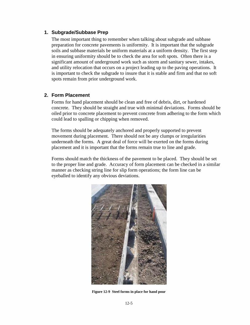
12-5
1. Subgrade/Subbase Prep
The most important thing to remember when talking about subgrade and subbase
preparation for concrete pavements is uniformity. It is important that the subgrade
soils and subbase materials be uniform materials at a uniform density. The first step
in ensuring uniformity should be to check the area for soft spots. Often there is a
significant amount of underground work such as storm and sanitary sewer, intakes,
and utility relocation that occurs on a project leading up to the paving operations. It
is important to check the subgrade to insure that it is stable and firm and that no soft
spots remain from prior underground work.
2. Form Placement
Forms for hand placement should be clean and free of debris, dirt, or hardened
concrete. They should be straight and true with minimal deviations. Forms should be
oiled prior to concrete placement to prevent concrete from adhering to the form which
could lead to spalling or chipping when removed.
The forms should be adequately anchored and properly supported to prevent
movement during placement. There should not be any clumps or irregularities
underneath the forms. A great deal of force will be exerted on the forms during
placement and it is important that the forms remain true to line and grade.
Forms should match the thickness of the pavement to be placed. They should be set
to the proper line and grade. Accuracy of form placement can be checked in a similar
manner as checking string line for slip form operations; the form line can be
eyeballed to identify any obvious deviations.
Figure 12-9 Steel forms in place for hand pour

12-6
When placed in curved sections, forms should be checked to insure that they have
been set to the proper radius. Forms should also be checked to insure that the
pavement will be built to the proper cross slope to allow drainage. Mainline paving is
typically placed before intersection returns and radius. It is important to check the
existing pavement to insure that it was built to the correct elevation. If the pavement
was not built to the correct elevation, then adjustments to the grade and or cross slope
may be necessary to insure that proper drainage is provided.
Figure 12-10 Forms should be checked to ensure proper drainage
3. Objects in or Under Pavement
When the subgrade or subbase will not be used as a haul road for delivery of concrete
to the paving operation, fixtures within the pavement should be placed well ahead of
the start of paving. Boxouts for intakes and utility accesses, fixtures that are cast in
place, traffic signal handholes and preformed loops, CD baskets (when used), tie bars,
and wire fabric should all be in place at the start of paving to minimize disruptions in
the progress of the work.

12-7
Figure 12-11 Placement of tie bars and CD baskets prior to paving
4. Concrete Placement
There are several types of machines that may be used when placing concrete
pavement by hand methods. Most often a vibratory type screed or a tube type roller
screed will be used. Occasionally a bridge deck finishing machine may be used.
Each of these types of screeds does impart some vibration into the slab, but use of
supplementary vibration is recommended for most placements and necessary for
thicker placements (greater than 9 inches) and reinforced pavements.
12-12 Roller Screed 12-13 Vibratory Truss Screed
Because each of these types of screeds is much smaller than a slip form paver, it is
important to place concrete evenly in front of them to allow them to uniformly strike
off the concrete and produce a smooth surface. While placing concrete from the
chute of the delivery truck does place the concrete close to the desired location,
12-8
typically additional manipulation is necessary. Vibrators should never be used for
this as they can cause segregation when used to move concrete. Only shovels should
be used to move concrete to provide a uniform head in front of the screed.
5. Finishing
When finishing pavements placed using hand methods, it is important to remember
that all concrete adjacent to forms must be edged using an edging tool. This is
important because edging rounds the corner of the slab and provides a break between
the forms and the concrete, preventing tearing or spalling of the concrete when the
form is removed.
Fixtures in the pavement should also receive special attention during finishing to
ensure that they blend in with the surrounding pavement and will not create a bump,
dip, or a snag point for snow removal equipment.
D. Obstructions
Due to the confined work areas on urban projects, paving beside, around, and over
obstacles often cannot be avoided. These obstructions can be anything from utilities and
trees to historic landmarks. The general rule for these situations is to make everyone
aware of potential conflicts before construction begins in order to avoid as many
problems as possible.
The agency needs to consider the clearance needed to accommodate the paver track and
the clearances needed for other equipment. If the back of curb will fall too close to
obstructions that can be moved, those arrangements need to be made long before the
contractor arrives on the project site. Delays in the construction can result if utilities, for
instance, are not moved in a timely manor. As much lead-time as possible should be
given in order to avoid a conflict.

12-9
Figure 12-14 Pavement edge next to utility access
Figure 12-15 Pave around the pole
Additional gaps, boxouts and pavement joints may be required for machine clearances.
Also consideration needs to be given to the elevation of adjacent objects, such as fire
hydrants. The final elevations should be adjusted to coordinate with the paving elevation.
Figure 12-16 Fire hydrant placed too high
E. Jointing
Correct jointing is critical for a quality and long lasting pavement. Care should be taken
to see that the plans are followed in regards to joint spacing and placement. Most plans
will show a standard or typical joint spacing and will have additional details for
intersections. It’s a good idea to layout intersections and driveways first and then
transition back to standard spacing for mainline joints. Despite taking all precautions

12-10
possible pavement joints can still end up in the wrong location. Whenever possible,
adjust the location of planned joints to match existing joints in order to minimize random
cracking. Extreme cases can require removal and replacement to correct deficiencies.
Figure 12-17 Longitudinal joints mismatched
F. Access Locations
When the project first begins, the inspector and the contractor need to check the plans and
then physically compare the sidewalk and driveway locations to the plan locations. This
needs to be done early. That way there is enough time to coordinate any of the abutting
pavements with the new slab and proposed joints before the paving operation begins.
Often they may involve redesigning the connection if the existing pavement is at a
different elevation than what was shown on the plans. It can be embarrassing if the new
drive does not lead to the garage door!
Figure 12-18 Driveway jointing does not match mainline
Figure 12-19 Jointing for acesses must be carefully
considered

A
PP
EN
DIX
A
R
ES
OU
RC
ES


A-1
Appendix A Resources

A-2
INSPECTOR’S TOOL KIT
SPECIFICATION BOOK SUPPLEMENTAL SPECIFICATIONS ROAD STANDARDS MATERIALS I.M.’S COPY OF FORMS OR SMALL BOOK PEN OR PENCIL CALCULATOR AIR METER SLUMP CONE BEAM BOXES BUCKETS SQUARE NOSE SHOVEL RAGS RUBBER GLOVES CAN OF SPRAY PAINT MAGIC MARKER SMALL TROWEL NUMBERS FOR STATIONING 6’ RULER – ENGLISH/METRIC 4’ LEVEL STRING VIBRATOR CHECKER PAVEMENT DEPTH CHECKER TIRE DEPTH GAUGE – CHECKING TEXTURE HARD HAT SAFETY VEST WATER SNACK FOOD SUN BLOCK

A-3
PV-101

A-4
PV-101

A-5
PV-101

A-6
PV-101

A-7
PV-101

A-8
PV-101

A-9
PV-101

A-10
PV-101

A-11
Form E109 Sub Grade/Final Check
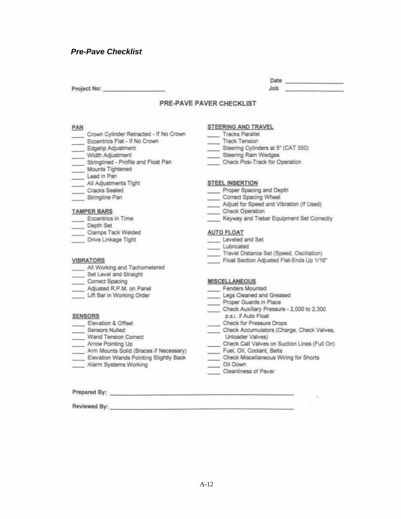
A-12
Pre-Pave Checklist

A-13
Form 830213 Project Information/Paver Inspection

A-14
Form 830212 Ready Mix Concrete

A-15
Form E137 PCC Pavement Field Page

A-16
Form E115 Air and Slump Tests

A-17
Form E110 Depth Checks

A-18
Form E111 PC Concrete Items Checklist

A-19
Form E114 PC Concrete Beams Record

A-20
Form E141 Maturity Record

A-21
Form M142 Maturity Field Data Recording Sheet

A-22
Form E140 Tining Depth Checks

A-23
Form 800240 Daily PCC Plant Report

A-24
Form 821283 PCC Gradation Test Report – Verification

A-25
Form 830245 Noncompliance Notice

A-26
Pavement Worksheet

A-27
Texture Check Worksheet

A-28
Joint Check Worksheet

A-29
Elevation Check Worksheet


A
PPEND
IX B
C
HEC
KLIST


B-1
Appendix
B
PC
C P
avin
g F
ield
In
sp
ection
Ch
ecklis
t

B-2
PC
C P
avin
g F
ield
In
sp
ecti
on
Ch
ec
kli
st
Du
ty
Fre
qu
en
cy
R
ec
ord
S
pec
ific
ati
on
/Re
so
urc
e
Co
mm
en
tary
Ch
ec
ks
Pri
or
to C
on
cre
te P
lac
em
en
t
Che
ck p
roof
rolli
ng
Eve
ryw
he
re p
rio
r to
S
pe
cific
ation
230
1.0
3,
B, 3
all
PC
C p
avin
g
All
su
bg
rad
es s
ho
uld
be p
roof ro
lled
with
a s
he
ep
's f
oo
t ro
ller
of
sub
gra
de
fin
al tr
imm
ing
of
S
pe
cific
ation
211
5.0
3,
B, 2
M
od
ifie
d S
ub
base
no
mo
re t
ha
n 1
we
ek p
rio
r to
trim
min
g o
f th
e f
ina
l g
rade
. In
su
bg
rad
e.
ad
ditio
n, w
he
n M
od
ifie
d S
ub
ba
se
is u
sed
, th
e s
ub
gra
de
is to
be
pro
of
rolle
d w
ith
a loa
ded
tru
ck to
id
en
tify
so
ft s
po
ts,
etc
.
C
he
ck s
trin
glin
e
As n
eed
ed
Pri
or
to c
heckin
g s
ub
gra
de
and
sub
base
cro
ss s
lope
and
ele
va
tion
, ch
eck to
ensu
re t
hat th
e s
trin
glin
e is p
rop
erly p
laced
rela
tive
to
the
pa
vin
g h
ub
. T
his
can
be d
one
sim
ply
by
me
asu
rin
g f
rom
th
e p
avin
g h
ub
up
to
th
e s
trin
glin
e.
Ma
ke
su
re
to f
acto
r in
th
e c
on
tra
cto
r's m
ach
ine
co
nsta
nt
wh
en
me
asu
rin
g.
C
he
ck t
rim
med
10
/mile
(IM
-20
4)
Fo
rm E
10
9
Sp
ecific
ation
210
9.0
3,
A, 1
0
Che
ck t
o e
nsu
re s
ub
gra
de
is trim
me
d to
th
e p
rope
r cro
ss
su
bg
rad
e
plu
s o
r m
inus 0
.05
fo
ot
slo
pe
and
ele
va
tion
. U
su
ally
ch
ecke
d b
y p
lacin
g s
trin
g a
cro
ss
su
bg
rad
e fro
m s
trin
glin
e t
o s
trin
glin
e a
nd
me
asu
rin
g d
ow
n t
o
top
of sub
gra
de
. W
he
n s
trin
glin
e is n
ot a
va
ilab
le,
a s
urv
ey r
od
an
d le
ve
l m
ay b
e u
se
d.
La
se
r le
ve
ls h
ave
bee
n u
sed
bu
t a
re
less c
om
mo
n. G
PS
ro
ve
rs h
ave
als
o b
een
use
d, b
ut a
re n
ot
accu
rate
en
ou
gh
to
me
asu
re w
ith
in t
he
sp
ecific
ation
tole
ran
ces.
Ma
ke
su
re t
he
As n
eed
ed
S
pe
cific
ation
211
1.0
3,
E
Th
e s
pe
cific
atio
n p
rohib
its t
he
co
ntr
acto
r fr
om
dri
vin
g o
n t
he
co
ntr
acto
r is
no
t
gra
nu
lar
su
bba
se m
ate
rial.
This
is a
con
ce
rn b
eca
use
dri
vin
g h
aul ve
hic
les
exce
ssiv
e h
au
l tr
aff
ic o
n t
he g
ran
ula
r sub
base
ma
teri
al can
on
gra
nu
lar
ca
use
the
ma
teria
l to
bre
ak d
ow
n a
nd
ge
ne
rate
an
exce
ssiv
e
su
bba
se
a
mo
un
t o
f fine
s. T
his
is u
nd
esir
ab
le b
eca
use
gra
nula
r
su
bba
se is in
ten
ded
to b
e a
dra
ina
ble
ma
teri
al.
Ha
ul
eq
uip
men
t m
ust b
e o
pe
rate
d o
n t
he
ma
teri
al fo
r d
eliv
ery
an
d
pla
ce
men
t pu
rposes.
A r
ea
son
ab
le e
xp
ecta
tio
n o
f th
e
co
ntr
acto
r is
th
at
the
y g
et
on
an
d o
ff th
e m
ate
rial w
ith
in a
50
0
to 1
000
foo
t str
etc
h.
Whe
n r
ecycle
d m
ate
rials
are
used
, th
e
dis
tan
ce
sh
ou
ld b
e k
ep
t clo
se
r to
500
fee
t. W
he
n v
irg
in
ma
teria
ls a
re u
se
d,
the
dis
tance
can
be
exte
nd
ed
up
to
10
00
fee
t de
pe
nd
ing
upo
n h
ow
mu
ch
bre
akd
ow
n o
f th
e m
ate
ria
l
o
ccu
rs.

B-3
PC
C P
avin
g F
ield
In
sp
ecti
on
Ch
ec
kli
st
Du
ty
Fre
qu
en
cy
R
ec
ord
S
pec
ific
ati
on
/Re
so
urc
e
Co
mm
en
tary
Ch
ec
ks
Che
ck t
rim
med
10
/mile
(IM
-20
4)
Fo
rm E
10
9
Mo
difie
d S
ub
ba
se
Ch
eck t
o e
nsu
re s
ub
ba
se is t
rim
med
to
th
e p
rop
er
cro
ss s
lope
su
bba
se (
gra
nu
lar
Sp
ecific
ation
211
5.0
3 p
lus 0
an
d m
inus 0
.05
foo
t a
nd
ele
va
tion
. T
his
, alo
ng w
ith
th
e s
ubg
rade
ch
ecks, w
ill
or
mod
ifie
d)
IM 2
04
Ap
pe
ndix
C
en
su
re p
rop
er
su
bb
ase
thic
kne
ss. U
sua
lly c
hecked
by p
lacin
g
str
ing
acro
ss s
ub
ba
se f
rom
str
ing
line
to s
trin
glin
e a
nd
G
ran
ula
r S
ub
base
me
asu
rin
g d
ow
n t
o t
op
of
su
bb
ase.
When
str
ing
line
is n
ot
S
pe
cific
ation
211
1.0
3,
D, 4
p
lus 0
an
d m
inu
s 0
.05
ava
ilable
, a
le
ve
l m
ay b
e u
se
d.
Lase
r le
ve
ls h
ave
be
en
used
fo
ot
bu
t a
re less c
om
mo
n.
GP
S r
ove
rs h
ave
als
o b
een
use
d, b
ut
IM
20
4 A
pp
en
dix
D
are
no
t a
ccu
rate
. T
he
wid
th o
f th
e s
ub
ba
se s
ho
uld
als
o b
e
ch
ecked
at th
is t
ime
to
ensu
re th
at
the
pro
pe
r p
lacem
en
t w
idth
is
be
ing a
ch
ieve
d.
No
te t
ha
t su
bb
ase
wid
th t
yp
ically
inclu
des
an
add
ed
th
ree f
ee
t o
n e
ach
sid
e o
f th
e p
ave
men
t fo
r a
pa
dlin
e.
Che
ck s
tee
l
S
pe
cific
ation
415
1.0
3,
G
Ste
el re
info
rce
me
nt
sh
ou
ld b
e s
tore
d in
a m
an
ne
r th
at
red
uce
s
rein
forc
em
en
t
the
ris
k o
f co
rrosio
n,
dam
ag
e, a
nd
bre
akd
ow
n o
f e
po
xy
sto
rag
e
co
atin
g. A
ll re
info
rce
men
t is
to
be
sto
red
on s
up
po
rts to
pre
ve
nt
co
nta
ct
with
th
e g
rou
nd
an
d e
xte
nd
ed
co
nta
ct
with
mo
istu
re.
Ep
oxy c
oa
ted b
ars
sh
ould
be
co
ve
red
with
a n
on
-
tr
an
sp
are
nt
ma
teria
l if e
xp
osed
fo
r 2 m
on
ths o
r m
ore
.
C
he
ck d
ow
el b
aske
t F
orm
E11
1
Sp
ecific
ation
230
1.0
3,
E
Do
we
l b
aske
ts s
hou
ld b
e c
hecke
d fo
r sp
acin
g, a
lignm
en
t,
pla
ce
men
t
S
pe
cific
ation
415
1.0
2,
B
pro
pe
r a
nch
ora
ge
, an
d a
de
qua
te b
on
d b
reake
r co
atin
g. A
Roa
d S
tan
da
rd P
V-1
01
qu
ick a
nd
sim
ple
me
tho
d to
che
ck a
lign
me
nt is
to
sig
ht
do
wn
P
avin
g t
yp
ica
ls in B
sh
ee
ts o
f p
roje
ct
pla
ns
the
gra
de
. B
aske
ts t
ha
t a
re o
ut
of
alig
nm
en
t w
ill b
e v
isib
le a
s
the
do
we
ls w
ill n
ot lin
e u
p.
Th
e b
aske
ts s
ho
uld
als
o b
e
ch
ecked
to
en
su
re th
at
the
dow
el b
ars
are
le
ve
l a
nd p
ara
llel
with
ea
ch
oth
er.
It
is im
po
rta
nt to
ch
eck a
lign
men
t o
f d
ow
els
to
ensu
re th
at th
e c
ontr
actio
n jo
int
wo
rks p
rope
rly in
th
e
pa
ve
me
nt.
O
nce
the
join
t is
sa
we
d a
nd
the
pa
vem
en
t cra
cks,
the
co
ncre
te is in
ten
ded
to
slid
e o
ve
r th
e d
ow
el as t
he
pa
ve
me
nt
exp
an
ds a
nd
co
ntr
acts
. I
f th
e d
ow
els
are
ou
t o
f
a
lign
men
t, th
e p
ave
me
nt
ca
nno
t p
rope
rly s
lide
on
th
e d
ow
els
w
hic
h m
ay r
esu
lt in
ra
ndo
m c
rackin
g.

B-4
PC
C P
avin
g F
ield
In
sp
ecti
on
Ch
ec
kli
st
D
uty
F
req
uen
cy
R
eco
rd
Sp
ecif
icati
on
/Reso
urc
e
Co
mm
en
tary
Ch
ec
ks
Baskets
should
be a
nch
ore
d w
ith a
min
imum
of
8 b
asket
sta
kes
per
lane w
idth
. D
ow
el baskets
are
requir
ed t
o b
e c
oate
d w
ith a
bon
d b
reaker.
Typic
ally
the b
on
d b
reakers
used a
re a
bitum
inou
s
mate
rial or
a p
ara
ffin
based m
ate
rial calle
d T
ecty
l. O
ften t
he
bitum
inous c
oating c
an b
ecom
e d
ry a
nd b
ritt
le a
nd w
ill d
evelo
p
cra
cks in t
he m
ate
rial. If th
is o
ccurs
, re
coating o
f th
e b
ars
may
be n
ecessary
. T
he c
ontr
acto
r is
not
requir
ed t
o c
ut
the t
ie w
ires
on t
he b
askets
as long a
s t
he b
asket is
manufa
ctu
red c
orr
ectly.
The P
V-1
01 r
oad s
tand
ard
show
s t
hre
e #
10 g
au
ge w
ires o
n t
he
basket.
If
more
than t
hre
e w
ires a
re p
rovid
ed,
only
thre
e m
ay b
e
left
uncut.
One f
inal check that
should
be m
ad
e f
or
dow
el
baskets
is to c
heck t
hat
the c
ontr
acto
r has m
ark
ed t
he c
ente
r of
each e
nd o
f th
e b
asket
to identify
the location o
f th
e b
asket
for
purp
oses o
f saw
ing.
this
is t
ypic
ally
don
e b
y p
lacin
g a
basket
sta
ke o
ff e
ach e
nd o
f th
e b
asket
alo
ng w
ith a
pain
t m
ark
. In
spe
ct
the
fin
ish
ing O
nce
each
pa
ve
r an
d
Fo
rm 8
30
21
3
Sp
ecific
ation
230
1.0
3,
A, 3
A f
ew
da
ys p
rio
r to
sta
rt o
f p
avin
g, se
ve
ral che
cks s
hou
ld b
e
ma
ch
ine
wh
en
in
form
atio
n
C
on
str
uctio
n M
an
ua
l A
pp
end
ix 9
-3
ma
de o
n th
e p
ave
r, a
nd
fo
rm 8
30
213
sh
ould
be
co
mple
ted
.
ch
ang
es.
Use
this
fo
rm to
reco
rd v
ibra
tor
sp
acin
g a
nd
ang
le.
Th
e p
ave
r
w
idth
an
d c
ross s
lope
sh
ould
als
o b
e c
hecke
d.
Th
e fo
rm c
an
als
o b
e u
sed
to
re
co
rd v
ibra
tor
fre
qu
en
cy c
he
cks d
urin
g
pa
vin
g.
Che
ck p
ave
r
S
pe
cific
ation
230
1.0
3,
A, 3
, a
Dis
cuss la
yo
ut o
f vib
rato
rs w
ith
con
tra
cto
r to
con
firm
lo
cation
s
vib
ratio
n m
on
ito
rin
g
V
ibra
tio
n m
onito
rin
g r
eq
uire
d fo
r a
ll p
roje
cts
with
of
each
rela
tive
to
da
ta b
ein
g r
eco
rde
d o
n m
on
ito
ring
syste
m.
syste
m
ma
inlin
e p
avin
g q
ua
ntities g
rea
ter
tha
n 5
0,0
00
sq
ua
re y
ard
s
Che
ck p
ave
r O
nce
each
pa
ve
r an
d
Sp
ecific
ation
230
1.0
3 A
, 3,
a
Re
co
rd o
n fo
rm 8
30
21
3.
Sp
acin
g m
ay b
e in
cre
ase
d d
ue
to
vib
rato
r sp
acin
g
ea
ch t
ime
the
pa
ve
r
16
inch
ma
xim
um
sp
acin
g
str
uctu
ral lim
ita
tion
s o
f fin
ish
ing
mach
ine
. G
rea
ter
sp
acin
g
w
idth
is c
ha
ng
ed
.
sh
ould
no
t be
allo
we
d f
or
tie
ste
el in
se
rtio
n o
r la
ck o
f co
rre
ct
nu
mbe
r o
f vib
rato
rs.
Che
ck p
ave
r O
nce
each
pa
ve
r.
S
pe
cific
ation
230
1.0
3 A
, 3,
a
Re
co
rd o
n fo
rm 8
30
21
3.
vib
rato
r an
gle
V
ibra
tors
sh
ou
ld b
e m
ou
nte
d p
ara
llel to
dir
ectio
n o
f
p
avin
g a
nd
tra
ilin
g e
nd
tilt
ed
to a
pp
roxim
ate
ly 1
5
d
eg
rees b
elo
w h
ori
zo
nta
l

B-5
PC
C P
avin
g F
ield
In
sp
ecti
on
Ch
ec
kli
st
Du
ty
Fre
qu
en
cy
R
ec
ord
S
pec
ific
ati
on
/Re
so
urc
e
Co
mm
en
tary
Ch
ec
ks
Du
rin
g C
on
cre
te P
lacem
en
t
Pla
ce d
ate
in
Daily
T
he
da
te s
ho
uld
be
sta
mp
ed
in
th
e h
ea
de
rs a
t th
e b
eg
inn
ing
he
ad
ers
an
d e
nd
of e
ach
da
y's
ru
n. T
he
da
te s
ho
uld
be
pla
ce
d in
th
e
ou
ter
2 f
eet
of
the
pa
ve
men
t in
a p
ositio
n w
he
re it
will
not
be
de
str
oye
d b
y p
ossib
le m
illed
sh
ou
lde
r ru
mb
le s
trip
pla
cem
ent.
C
he
ck
As n
eed
ed.
S
pe
cific
ation
210
9.0
3,
B
Th
e s
ub
gra
de
or
su
bb
ase
sh
ou
ld b
e p
erio
dic
ally
ch
ecke
d
su
bg
rad
e/s
ubb
ase
S
pe
cific
ation
230
1.0
3,
B
thro
ugh
ou
t th
e p
avin
g d
ay t
o e
nsu
re t
ha
t th
e m
ate
rial is
m
ois
ture
un
ifo
rmly
mo
ist.
M
ois
ture
sh
ou
ld b
e a
dd
ed
as n
ee
de
d to
kee
p
the
ma
teri
al in
a u
nifo
rmly
mo
ist
co
nd
itio
n.
As t
he
su
bg
rad
e o
r
su
bba
se m
ate
rial d
rie
s o
ut, m
ois
ture
will
be
wic
ked
ou
t o
f th
e
co
ncre
te a
nd
can
ca
use
loss o
f str
en
gth
an
d r
ed
uctio
n in
eff
ective
pa
vem
en
t th
ickn
ess. A
fte
r p
eri
ods o
f ra
in,
ad
ditio
n o
f
m
ois
ture
ma
y n
ot
be n
ece
ssa
ry if
su
ffic
ien
t m
ois
ture
is
pre
sen
t.
Che
ck d
ow
el
Pe
rio
dic
ally
Sp
ecific
ation
230
1.0
3,
E
It is a
goo
d p
ractice
to
pe
rio
dic
ally
wa
lk o
ut in
fro
nt o
f th
e
ba
ske
ts
p
avin
g t
rain
an
d c
heck t
o m
ake
su
re d
ow
el b
aske
ts a
re s
till
in
pro
pe
r a
lign
me
nt a
nd
fre
e f
rom
con
tam
ina
tion
. O
ccasio
na
lly
ba
ske
ts c
an
becom
e d
am
ag
ed o
r con
tam
ina
ted
with
mu
d o
r
o
the
r de
bris d
uri
ng
han
dlin
g a
nd
pla
cem
en
t.
Th
ese
baske
ts
sh
ould
be
cle
an
ed
an
d r
ep
air
ed
or
rem
ove
d a
nd
re
pla
ced
.
C
he
ck join
t la
yo
uts
A
s n
eed
ed
S
pe
cific
ation
230
1.0
3,
E
Th
ere
are
ce
rtain
lo
catio
ns o
n a
pro
ject
wh
ere
sp
ecific
jo
int
K
an
d L
she
ets
in p
roje
ct
pla
ns
typ
es a
nd
sp
acin
gs a
re r
equ
ire
d.
Are
as s
uch
as t
urn
lan
es,
pa
ve
d c
rosso
ve
rs, a
nd s
ide
roa
d c
on
nectio
ns w
ill h
ave
a
sp
ecific
jo
intin
g la
yo
ut in
clu
ded
in
th
e K
an
d L
she
ets
of th
e
pro
ject
pla
ns.
It
is im
po
rta
nt
to r
evie
w t
he
pro
ject
pla
ns a
nd
insp
ect
the
co
ntr
acto
rs jo
intin
g la
yo
ut
pri
or
to p
lacin
g c
on
cre
te.

B-6
P
CC
Pavin
g F
ield
In
sp
ecti
on
Ch
ec
kli
st
Du
ty
Fre
qu
en
cy
R
ec
ord
S
pec
ific
ati
on
/Re
so
urc
e
Co
mm
en
tary
Ch
ec
ks
Che
ck c
on
cre
te
At
sta
rt o
f co
ncre
te
Rea
dy m
ix -
Sp
ecific
ation
230
1.0
2,
C, 4
Th
e s
pe
cific
atio
n r
eq
uir
es t
ha
t co
ncre
te h
aule
d w
ith
ou
t d
eliv
ery
tim
e
pla
ce
men
t an
d w
he
n
Fo
rm 8
30
21
2
co
ntin
uou
s a
gita
tion
be
pla
ced w
ith
in 3
0 m
inu
tes a
fte
r
de
live
ry r
ou
tes o
r C
en
tra
l b
atc
h -
b
atc
hin
g.
Th
is t
ime
ma
y b
e e
xte
nd
ed
an
ad
ditio
na
l 3
0 m
inu
tes
d
ista
nce
s c
han
ge
N/A
wh
en
a r
eta
rde
r is
use
d w
ith
ap
pro
va
l of
the E
ngin
ee
r.
Co
ncre
te h
au
led
with
con
tinu
ou
s a
gita
tio
n m
ust
be
pla
ce
d
with
in 9
0 m
inu
tes a
fte
r b
atc
hin
g.
When
usin
g r
ead
y m
ix
co
ncre
te, th
e t
ime
ba
tch
ed
sho
uld
be
in
clu
ded
on F
orm
8
30
212
(R
ead
y M
ix C
on
cre
te)
wh
en
re
ce
ive
d o
n g
rad
e.
Aft
er
dis
ch
arg
e,
the
dis
ch
arg
e t
ime
sh
ould
als
o b
e r
eco
rde
d o
n the
form
. F
or
ce
ntr
al ba
tch
co
ncre
te,
hau
l ro
ute
s a
nd
hau
l tim
es
sh
ould
be
dis
cu
sse
d w
ith
th
e c
on
tracto
r p
rio
r to
pla
ce
men
t.
Fa
cto
rs s
uch
as d
ela
ys d
ue
to
he
avy t
raff
ic (
i.e
. -
rush
ho
ur
in
an
urb
an
are
a)
sh
ould
be
dis
cu
sse
d a
lon
g w
ith
po
ssib
le
alte
rna
te h
au
l ro
ute
s. H
au
l tim
es s
ho
uld
be
obse
rve
d a
nd
reco
rde
d in
the
daily
dia
ry f
or
the
pro
ject.
C
he
ck a
nd
Ea
ch
lo
ad
Fo
rm 8
30
21
2
Sp
ecific
ation
230
1.0
2,
C, 4
Re
co
rd w
ate
r ad
ded
to
ea
ch
loa
d o
n th
e r
ea
dy m
ix t
icke
t fo
r d
ocum
ent
wa
ter
th
at
loa
d. T
ota
l w
ate
r a
dd
ed
to
all
load
s fo
r th
e p
lace
men
t a
dd
ed o
n g
rad
e
sh
ould
be
to
tale
d a
nd
re
po
rte
d t
o t
he p
lan
t in
sp
ecto
r fo
r
in
clu
sio
n o
n t
he
pla
nt
rep
ort
.
Che
ck c
on
cre
te
Pe
rio
dic
ally
Sp
ecific
ation
230
1.0
3,
F
Co
ncre
te s
ho
uld
be
pla
ced
in a
man
ne
r th
at m
inim
ize
s
pla
ce
men
t
S
pe
cific
ation
230
1.0
3, J
se
gre
ga
tio
n a
nd
dis
turb
an
ce o
f re
info
rce
men
t. W
he
n a
belt
op
era
tio
n
p
lace
r is
bein
g u
se
d, ch
eck to
ma
ke
su
re t
ha
t a
de
fle
cto
r is
in
pla
ce
and
bein
g u
se
d.
Th
is w
ill h
elp
to
min
imiz
e s
eg
reg
atio
n.
Du
rin
g h
an
d p
lacem
en
ts, h
an
d o
pe
rate
d v
ibra
tors
sh
ou
ld n
ot
be
use
d to
mo
ve
th
e c
on
cre
te. T
he
y s
ho
uld
only
be
used
fo
r
co
nso
lida
tio
n p
urp
oses.
Co
ncre
te p
lace
men
t sh
ould
als
o b
e m
on
ito
red
to
ensu
re t
hat
co
ncre
te d
oes n
ot
sit o
n t
he
gra
de
fo
r m
ore
tha
n 3
0 m
inu
tes
be
fore
con
solid
ation
and
fin
ishin
g.
Th
is is t
o e
nsu
re th
at
the
co
ncre
te is p
lastic a
nd
wo
rka
ble
wh
en
co
nso
lidate
d a
nd
fin
ish
ed b
y t
he
fin
ishin
g m
ach
ine
.
Te
st
slu
mp
of
Min
imu
m 1
/70
0 C
Y
Fo
rm E
11
5
Sp
ecific
ation
230
1.0
2,
B, 3
Th
ere
are
no
slu
mp
re
qu
irem
en
ts fo
r slip
fo
rm p
ave
me
nt sin
ce
pla
stic c
on
cre
te
Min
imu
m o
f 1
test p
er
Fo
rm E
11
1
Slip
fo
rm p
avin
g N
/A
the
abili
ty o
f th
e p
avem
en
t to
ho
ld a
slip
pe
d e
dg
e g
ove
rns
p
lace
men
t
Non
-slip
form
pa
vin
g 0
.5"
to 4
" slu
mp
.
IM 2
04
Ap
pe
ndix
E,
IM 3
17

B-7
P
CC
Pavin
g F
ield
In
sp
ecti
on
Ch
ec
kli
st
Du
ty
Fre
qu
en
cy
R
ec
ord
S
pec
ific
ati
on
/Re
so
urc
e
Co
mm
en
tary
Ch
ec
ks
Te
st
en
train
ed
air
Min
imu
m 1
/70
0 C
Y
Fo
rm E
11
5
Sp
ecific
ation
230
1.0
2,
B, 4
As c
on
cre
te is p
lace
d, co
nsolid
ate
d, a
nd
fin
ish
ed
, a
ir
co
nte
nt
of
pla
stic
Min
imu
m 1
/10
0 C
Y f
or
Fo
rm E
11
1
Slip
fo
rm p
avin
g ta
rget
of 8
% w
ith
a t
ole
ran
ce
of
en
tra
inm
en
t is
lo
st.
It is d
esir
ab
le to
ha
ve
an
entr
ain
ed
air
co
ncre
te
tra
nsit m
ix
p
lus o
r m
inus 2
%
co
nte
nt
of
app
roxim
ate
ly 6
% a
fte
r fin
ish
ing
. T
he
sp
ecific
ation
M
inim
um
of 1
test p
er
N
on
slip
fo
rm p
avin
g ta
rge
t o
f 7
% w
ith
a t
ole
ran
ce
limits fo
r air
co
nte
nt
are
set
up t
o a
ccou
nt
for
air loss d
urin
g
p
lace
men
t
of
plu
s o
r m
inus 1
.5%
p
lace
men
t an
d fin
ish
ing
. A
ir te
sts
sho
uld
occasio
na
lly b
e r
un
IM
204
Ap
pe
ndix
E,
IM 3
18,
IM 3
27,
IM 5
27
, IM
530 b
eh
ind
the
pa
ve
r to
co
nfirm
tha
t th
e a
nticip
ate
d a
ir loss is
C
on
str
uctio
n M
an
ua
l 9
.63
occu
rrin
g a
nd
th
at
the d
esir
ed
air
co
nte
nt
is a
ch
ieve
d.
It is
re
co
mm
en
de
d t
ha
t a
ir lo
ss t
hro
ug
h t
he
pa
ve
r b
e c
he
cke
d o
nce
pe
r d
ay f
or
the f
irst
thre
e d
ays o
f p
avin
g o
n a
pro
ject.
A
fte
r
th
at,
ch
ecks s
ho
uld
be
ma
de
we
ekly
to
con
firm
the
am
ou
nt o
f
a
ir loss t
hro
ug
h th
e p
ave
r.
It is im
po
rtan
t th
at
ve
rification
te
sts
fo
r a
ir c
on
ten
t a
re r
an
dom
.
T
estin
g f
req
ue
ncy m
ust b
e r
and
om
in
ord
er
for
the t
est
to b
e
va
lid.
Te
stin
g s
hou
ld n
ot b
e p
erf
orm
ed
at re
gu
lar
inte
rvals
or
at
fixe
d t
ime
s e
ach
da
y.
On
QM
-C p
roje
cts
, ve
rifica
tio
n t
estin
g
sh
ould
no
t be
tim
ed t
o m
atc
h c
on
tracto
r qu
alit
y c
on
tro
l te
sting.
O
bse
rve
and
reco
rd A
s r
equ
este
d b
y
Fo
rm E
11
5
Con
str
uctio
n M
an
ua
l 9
.63
Co
ntr
acto
rs a
re o
nly
re
qu
ired
to
pe
rform
qu
alit
y c
on
tro
l (Q
C)
co
ntr
acto
r q
ua
lity
co
ntr
acto
r
te
stin
g o
n Q
M-C
pro
jects
. H
ow
eve
r, if
the
co
ntr
acto
r e
lects
to
co
ntr
ol air
tests
pe
rfo
rm Q
C t
estin
g o
n a
non
-QM
-C p
roje
ct,
te
stin
g s
ho
uld
be
witn
esse
d a
nd
do
cu
me
nte
d,
wh
en
re
qu
este
d b
y t
he
co
ntr
acto
r.
Fo
rm E
11
5 in
clu
de
s a
co
lum
n in
dic
atin
g w
he
the
r a
te
st is
a
witn
esse
d Q
C t
est o
r no
t. W
itn
essin
g a
nd d
ocum
en
tin
g
co
ntr
acto
r Q
C t
ests
is im
port
an
t b
eca
use
it
ma
y r
ed
uce
th
e
am
ou
nt
of
no
n-c
om
plia
nce
an
d/o
r te
stin
g t
ha
t a
co
ntr
acto
r m
ay
be
resp
onsib
le fo
r w
he
n n
on
-co
mp
lyin
g m
ate
ria
l is
id
en
tified
.

B-8
P
CC
Pavin
g F
ield
In
sp
ecti
on
Ch
ec
kli
st
Du
ty
Fre
qu
en
cy
R
ec
ord
S
pec
ific
ati
on
/Re
so
urc
e
Co
mm
en
tary
Ch
ec
ks
Ch
eck c
on
cre
te m
ix D
aily
wh
en
ne
ar
Fo
rm E
11
1
Sp
ecific
ation
230
1.0
3,
S
It is im
po
rtan
t to
che
ck c
on
cre
te t
em
pe
ratu
res in
th
e e
arl
y
tem
pe
ratu
re
sp
ecific
atio
n lim
its
M
inim
um
40
deg
rees F
at
tim
e o
f p
lacem
en
t sp
ring
and
la
te fa
ll to
en
su
re th
at
the
min
imum
mix
te
mpe
ratu
res a
re a
ch
ieve
d.
Ea
rly s
prin
g is th
e m
ore
cri
tical
tim
e to
en
su
re m
inim
um
mix
te
mp
era
ture
s s
ince
the
su
bg
rad
e/s
ubb
ase
as w
ell
as a
ll of
the m
ix in
gre
die
nts
are
m
uch
co
lde
r a
fte
r th
e w
inte
r. T
yp
ica
lly m
ix t
em
pe
ratu
res a
re
no
t a
n issue
in
th
e la
te f
all
as th
e m
ix in
gre
die
nts
are
usua
lly
wa
rme
r th
an
th
e a
mbie
nt a
ir tem
pe
ratu
res.
While
Io
wa
do
es n
ot
ha
ve
an
up
pe
r lim
it fo
r co
ncre
te m
ix
tem
pe
ratu
res, te
mp
era
ture
s s
ho
uld
be
ta
ke
n a
nd
reco
rde
d
wh
en
co
mplic
atio
ns w
ith
air
entr
ain
me
nt o
r fin
ish
ing
are
e
ncou
nte
red
du
ring
hot
we
ath
er.
Che
ck p
ave
me
nt
At
sta
rt o
f pa
vin
g a
nd
Fo
rm E
11
1
Sp
ecific
ation
230
1.0
3,
A, 3
Sim
ilarl
y t
o c
he
cks m
ad
e o
n t
he
fin
ishin
g m
ach
ine
pri
or
to s
tart
wid
th a
nd
cro
ss
wh
en
pa
vin
g w
idth
s
S
pe
cific
ation
230
1.0
3,
F a
nd
G
of
pa
vin
g,
the
pa
vem
en
t itse
lf s
ho
uld
be
ch
ecke
d t
o e
nsu
re
slo
pe
ch
ang
e
P
avin
g t
yp
ica
ls in B
sh
ee
ts o
f p
roje
ct
pla
ns
tha
t th
e p
rop
er
wid
th a
nd
cro
ss s
lop
e a
re p
rovid
ed
. C
ross
slo
pe
ch
ecks c
an
be a
ccom
plis
he
d b
y r
un
nin
g a
str
inglin
e
acro
ss th
e p
ave
men
t fr
om
on
e s
trin
glin
e to
ano
the
r.
Me
asu
rem
en
ts c
an
th
en
be
ma
de
do
wn
fro
m t
he
str
inglin
e to
top
of p
ave
me
nt a
t ce
nte
rlin
e a
nd
bo
th p
ave
men
t ed
ges t
o
de
term
ine t
he c
ross s
lop
e o
f th
e p
avem
en
t.
C
he
ck d
epth
of
Daily
F
orm
E11
1
Sp
ecific
ation
230
1.0
3,
A, 3
Typ
ica
lly c
ontr
acto
rs c
he
ck t
he
th
ickn
ess o
f th
e p
ave
me
nt in
p
lastic c
on
cre
te
F
orm
E11
0
Pa
vin
g t
yp
ica
ls in B
sh
ee
ts o
f p
roje
ct
pla
ns
the
pla
stic c
on
cre
te t
o e
nsu
re th
at
the
y a
re p
avin
g p
lan
thic
kn
ess o
r th
icke
r. T
his
activity s
hou
ld b
e o
bse
rve
d b
y t
he
gra
de
in
sp
ecto
r o
r th
e g
rade
insp
ecto
r sh
ou
ld p
erf
orm
th
e
ch
ecks o
n th
eir
ow
n if
the
co
ntr
acto
r is
no
t.
Che
ck c
on
cre
te
1/1
000
CY
Fo
rm E
13
7
C
om
pa
rison
sh
ou
ld b
e m
ad
e b
etw
ee
n t
he
cu
bic
ya
rds o
f yie
ld
F
orm
E11
1
co
ncre
te b
atc
hed
and
th
e c
ub
ic y
ard
age
of co
ncre
te r
equ
ired
for
a g
ive
n a
rea
of p
ave
me
nt.
T
yp
ica
lly t
he
qu
antity
ba
tche
d
will
be
be
twe
en
10
3%
an
d 1
06%
of
the
qu
an
tity
re
quir
ed
.
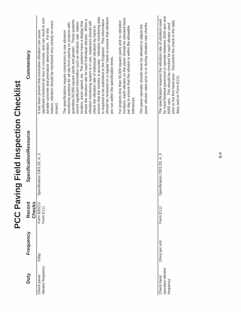
B-9
PC
C P
avin
g F
ield
In
sp
ecti
on
Ch
ec
kli
st
Du
ty
Fre
qu
en
cy
R
ec
ord
S
pe
cif
ica
tio
n/R
es
ou
rce
C
om
me
nta
ry
Ch
ec
ks
Che
ck p
ave
r 2
/da
y
Fo
rm 8
30
21
3
Sp
ecific
ation
230
1.0
3,
A, 3
It h
as b
ee
n p
rove
n t
ha
t e
xce
ssiv
e v
ibra
tion
ca
n c
ause
vib
rato
r fr
eq
uen
cy
Fo
rm E
11
1
sig
nific
an
t e
ntr
ain
ed
air
lo
ss in
co
ncre
te,
an
d c
an
re
su
lt in
no
n-
du
rab
le c
oncre
te a
nd
pre
ma
ture
de
teri
ora
tion
. F
or
this
re
ason
, vib
ratio
n s
ho
uld
be m
on
ito
red
ve
ry c
losely
on
eve
ry
pro
ject.
Th
e s
pe
cific
atio
ns r
equ
ire c
on
tra
cto
rs t
o u
se
vib
ratio
n
mo
nito
rin
g s
yste
ms fo
r a
ll slip
fo
rm p
avin
g o
n p
roje
cts
with
qu
an
tities 5
0,0
00
sq
ua
re y
ard
s a
nd
gre
ate
r. T
he
se
syste
ms
reco
rd s
ign
ific
an
t in
form
atio
n s
uch
as v
ibra
tion
ra
te,
sta
tio
n
locatio
n,
pa
ve
r sp
ee
d, e
tc. T
he
syste
ms h
ave
a d
isp
lay t
ha
t
sh
ow
s t
he
vib
ratio
n r
ate
fo
r e
ach
in
div
idu
al vib
rato
r. W
hen
a
vib
ratio
n m
on
ito
rin
g s
yste
m is in
use
, in
sp
ecto
rs s
ho
uld
still
ch
eck th
e v
ibra
tion
ra
te o
f in
div
idu
al vib
rato
rs b
y h
an
d t
o
en
su
re t
ha
t th
e m
on
ito
r is
accu
rate
. V
ibra
tio
n m
on
ito
rin
g d
ata
is
req
uire
d t
o b
e s
ubm
itte
d to
th
e E
ngin
ee
r.
Th
is in
form
atio
n
sh
ould
be
re
vie
we
d o
n a
reg
ula
r b
asis
to
en
sure
tha
t vib
rato
rs
are
ru
n w
ith
in t
he
sp
ecific
atio
n lim
its.
Fo
r p
roje
cts
le
ss t
ha
n 5
0,0
00
sq
ua
re y
ard
s a
nd n
o v
ibra
tio
n
mo
nito
rs,
each
vib
rato
r o
n t
he
pa
ve
r sho
uld
be
ch
ecke
d t
wic
e
pe
r d
ay t
o e
nsu
re th
at th
e v
ibra
tor
is w
ith
in th
e a
llow
ab
le
tole
ran
ces.
Th
e p
ave
r o
pe
rato
r sh
ou
ld n
eve
r b
e a
llow
ed
to a
dju
st th
e
pa
ve
r vib
rato
r ra
tes p
rio
r to
or
du
rin
g v
ibra
tio
n r
ate
ch
ecks.
C
he
ck h
and
On
ce
pe
r u
nit
Fo
rm E
11
1
Sp
ecific
ation
230
1.0
3,
A, 3
Th
e s
pe
cific
atio
n r
eq
uir
es t
he
vib
ratio
n r
ate
of
vib
rato
rs u
se
d
op
era
ted
vib
rato
r
for
ha
nd
fin
ish
ed p
ave
me
nt
to o
pe
rate
betw
ee
n 3
50
0 v
pm
and
fre
qu
en
cy
6
00
0 v
pm
. T
his
sho
uld
be
ch
ecked
fo
r e
ach
vib
rato
r use
d
pri
or
to t
he f
irst
ha
nd
po
ur.
D
ocu
me
nt
the
ch
eck in
th
e d
aily
d
iary
an
d o
n F
orm
E1
11
.

B-1
0
PC
C P
avin
g F
ield
In
sp
ecti
on
Ch
ec
kli
st
Du
ty
Fre
qu
en
cy
R
ec
ord
S
pec
ific
ati
on
/Re
so
urc
e
Co
mm
en
tary
Ch
ec
ks
Ch
eck c
en
terl
ine
tie
Daily
F
orm
E11
1
Sp
ecific
ation
230
1.0
3,
E
Th
e f
ina
l lo
ca
tio
n a
nd
alig
nm
en
t o
f tie
ste
el sh
ould
be
ch
ecke
d
ste
el in
se
rtio
n in
Roa
d S
tan
da
rd P
V-1
01
in t
he
pla
stic c
oncre
te b
eh
ind th
e f
inis
hin
g m
achin
e. O
fte
n a
p
lastic c
on
cre
te
h
ack s
aw
bla
de
or
tro
we
l is
inse
rte
d in
to th
e c
oncre
te a
t
ce
nte
rlin
e t
o d
ete
rmin
e th
e lo
ca
tio
n a
nd d
epth
of cen
terlin
e t
ie
ste
el.
On
ce
lo
ca
ted
at
ce
nte
rlin
e,
the
dep
th a
nd
alig
nm
en
t of
the
end
s o
f th
e b
ar
sho
uld
als
o b
e c
hecke
d t
o e
nsu
re th
at th
e
ba
r is
no
t shifte
d h
orizo
nta
lly o
r ve
rtic
ally
ou
t o
f alig
nm
en
t.
Sp
acin
g o
f tie b
ars
ca
n b
e d
ete
rmin
ed
by o
bse
rvin
g th
e
fre
qu
en
cy o
f in
se
rtio
n o
n t
he f
inis
hin
g m
ach
ine
.
C
he
ck f
inis
hin
g
Pe
rio
dic
ally
Sp
ecific
ation
230
1.0
3,
H
Th
e p
rim
ary
pu
rpose
fo
r h
an
d fin
ish
ing
be
hin
d t
he
fin
ish
ing
op
era
tio
n
m
ach
ine is t
o r
em
ove
sm
all
imp
erf
ection
s in
the
fin
al
pa
ve
me
nt
su
rface
an
d p
rovid
e a
unifo
rm s
urf
ace
. T
he
su
rface
of
the
sla
b s
ho
uld
be
ob
se
rve
d b
eh
ind
th
e f
inis
hin
g o
pe
ratio
n
to d
ete
rmin
e if
fin
ish
ing
ope
ratio
ns a
re a
de
qua
te. O
cca
sio
nal
"bu
g h
ole
s"
are
pe
rmis
sib
le, bu
t sho
uld
be
kep
t to
a m
inim
um
.
O
ve
rfin
ishin
g is a
lso
un
desir
able
as it ca
n a
ffe
ct p
ave
men
t
sm
oo
thn
ess a
nd
po
ten
tia
lly c
au
se
a lo
ss o
f e
ntr
ain
ed
air
at
the
su
rface
. A
bala
nce
mu
st
be
rea
ch
ed
betw
ee
n t
he
po
sitiv
e a
nd
ne
ga
tive
eff
ects
of finis
hin
g.
Du
rin
g fin
ish
ing
, fr
ee
wa
ter
may n
ot
be
ad
ded
to
th
e s
urf
ace o
f
th
e p
avem
en
t.
A s
mall
am
ou
nt
of
wa
ter
ma
y b
e a
dd
ed
to
a
bu
rla
p d
rag
atta
che
d to
th
e b
ack o
f th
e f
inis
hin
g m
achin
e. A
g
oo
d in
dic
ato
r th
at
too
mu
ch w
ate
r is
bein
g a
dde
d to
th
e
bu
rla
p d
rag
is t
he p
rese
nce
of b
ub
ble
s o
ff th
e t
raili
ng
en
d o
f
th
e b
urla
p.
An
oth
er
indic
ato
r th
at
exce
ssiv
e w
ate
r h
as b
ee
n
ad
de
d t
o th
e b
url
ap
is t
he c
olle
ction
of e
xce
ssiv
e a
mou
nts
of
mo
rta
r b
y t
he
flo
ats
. W
hen
exce
ssiv
e a
mo
un
ts o
f m
ort
ar
are
co
llecte
d,
this
ma
teria
l sh
ould
be
wa
ste
d o
ve
r th
e e
dge
of
the
pa
ve
me
nt
and
not
finis
he
d in
to t
he
su
rface
. A
dd
itio
n o
f w
ate
r
to
th
e b
urla
p s
hou
ld b
e r
estr
icte
d.
Che
ck s
tru
ctu
ral
Pe
rio
dic
ally
Roa
d S
tan
da
rd P
V-1
1
Ch
eck s
pa
cin
g a
nd
de
pth
of
str
uctu
ral ru
mble
str
ips in
pla
stic
rum
ble
str
ip
co
ncre
te.
pla
ce
men
t (w
he
n
req
uire
d)

B-1
1
PC
C P
avin
g F
ield
In
sp
ecti
on
Ch
ec
kli
st
Du
ty
Fre
qu
en
cy
R
ec
ord
S
pe
cif
ica
tio
n/R
es
ou
rce
C
om
me
nta
ry
Ch
ec
ks
Che
ck t
extu
re
Pe
rio
dic
ally
F
orm
E14
0
Sp
ecific
ation
230
1.0
3,
H
Mic
rote
xtu
re s
ho
uld
be
pla
ce
d u
sin
g a
rtific
ial tu
rf,
co
ars
e
pla
ce
me
nt
in p
lastic
Fo
rm E
11
1
Con
str
uctio
n M
an
ua
l 9
.40
ca
rpet,
or
bu
rla
p.
Pla
ce
men
t o
f m
icro
textu
re r
ou
ghe
ns t
he
co
ncre
te
p
ave
me
nt
su
rface
an
d p
rovid
es g
rip
fo
r tire
s t
o a
ssis
t w
ith
sto
pp
ing.
Ma
cro
textu
re (
tin
ing
) ca
n b
e p
lace
d e
ith
er
lon
gitu
din
ally
or
tra
nsve
rse
ly (
lon
gitu
din
al tinin
g is m
ost co
mm
on
).
Ma
cro
textu
re is p
lace
d t
o p
rovid
e a
bre
ak in
th
e p
ave
me
nt
su
rface
to
allo
w w
ate
r to
escap
e f
rom
und
er
tire
s d
urin
g a
rain
a
nd
red
uce
the
te
nd
ency f
or
hyd
rop
lanin
g. W
hen
tin
ing
is
pla
ce
d t
ran
sve
rse
ly,
a 4
to 6
inch
ga
p c
en
tere
d a
rou
nd
each
tra
nsve
rse
jo
int is
to
be
le
ft u
ntin
ed
. L
on
gitu
din
al tin
ing
sh
ould
b
e s
traig
ht
an
d a
s p
ara
llel to
ce
nte
rlin
e a
s p
ossib
le.
Th
e d
ep
th
of
tinin
g s
ho
uld
be
ke
pt
at o
r slig
htly le
ss t
ha
n t
he
sp
ecifie
d
1/8
" ta
rge
t to
min
imiz
e n
ois
e c
rea
ted
by t
ires in
tera
ctin
g w
ith
the
pa
vem
en
t su
rfa
ce
. W
he
n tin
ing
is p
laced
lon
gitu
din
ally
, a
2 t
o 3
inch
ga
p c
en
tere
d a
round
each
lo
ng
itu
din
al jo
int is
to
be
left
un
tine
d.
So
me c
on
tracto
rs h
ave
att
em
pte
d to
lea
ve
a
sin
gle
tin
e in
th
e c
en
ter
of th
e g
ap
ped
are
a a
s a
ma
rke
r fo
r th
eir
sa
win
g o
pe
ratio
n. T
his
pra
ctice
sh
ou
ld n
ot b
e a
llow
ed
d
ue
to c
on
ce
rns a
bou
t alig
nm
en
t o
f th
e c
ente
rlin
e s
aw
cu
t and
ra
ve
ling
.
Che
ck c
ure
bra
nd
Pe
rio
dic
ally
W
hite
pig
me
nt
cu
re is t
yp
ica
lly d
eliv
ere
d t
o a
pro
ject
in
an
d lo
t nu
mbe
r
reu
sab
le to
tes.
Th
e to
tes s
hou
ld p
eri
od
ica
lly b
e insp
ecte
d to
en
su
re t
ha
t th
e p
rop
er
bra
nd
an
d lot
num
be
r o
f th
e c
ure
are
id
en
tified
on t
he t
ote
. T
he
lot n
um
be
r sh
ould
als
o b
e c
ross
ch
ecked
with
th
e lis
t o
f a
pp
rove
d lots
of
cu
re f
ou
nd
on
th
e
Off
ice
of
Ma
teri
als
we
b s
ite
.

B-1
2
PC
C P
avin
g F
ield
In
sp
ecti
on
Ch
ec
kli
st
Du
ty
Fre
qu
en
cy
R
ec
ord
S
pe
cif
ica
tio
n/R
es
ou
rce
C
om
me
nta
ry
Ch
ec
ks
Che
ck c
ure
P
eri
odic
ally
fo
r F
orm
E11
1
Sp
ecific
ation
230
1.0
3,
K
Th
e s
pe
cific
atio
ns r
equ
ire c
ure
pla
ce
me
nt
with
in 3
0 m
inu
tes
pla
ce
men
t u
nifo
rmity o
f co
ve
rag
e
a
fte
r fin
ish
ing
. T
imin
g o
f cu
re p
lace
men
t sh
ould
be
ob
se
rve
d
D
aily
fo
r yie
ld
thro
ugh
ou
t e
ach
da
y t
o e
nsu
re t
ha
t th
is r
equ
irem
en
t is
be
ing
me
t.
Th
e s
pecific
ation
als
o a
llow
s a
n e
xte
nsio
n o
f th
e 3
0
min
ute
req
uire
men
t w
he
n w
ea
the
r a
nd
/or
mix
pro
pe
rtie
s
req
uire
an
exte
nd
ed
pe
rio
d b
efo
re c
uri
ng.
Th
is is a
llow
ed
to
en
su
re t
inin
g c
an
be
pla
ce
d a
t th
e p
rop
er
de
pth
. I
f a
mix
is s
till
too
pla
stic w
ith
in t
he
30
min
ute
s a
fte
r fin
ish
ing
, it is n
ot
de
sira
ble
to
pro
ce
ed
with
tin
ing
an
d c
urin
g if
the
tin
ing
dep
th
will
be
to
o d
eep
.
Cu
re p
lacem
ent
sho
uld
be c
hecked
to
en
su
re u
nifo
rmity o
f
a
pp
lica
tio
n.
Str
ea
ks s
ho
uld
be m
inim
al an
d a
rea
s o
f vis
ible
g
ray s
hou
ld b
e r
ecu
red
. Y
ield
ch
ecks s
ho
uld
be p
erf
orm
ed
da
ily b
ased
upo
n t
ota
l cu
re a
pp
lied
th
rou
gho
ut
the
da
ys r
un
an
d t
he
tota
l sq
ua
re y
ard
ag
e o
f p
ave
men
t cu
red inclu
din
g t
he
sid
es o
f th
e p
ave
me
nt.
If
fo
rms a
re u
sed
to s
up
po
rt t
he
ed
ge
of
pa
ve
me
nt, t
he
pa
ve
me
nt
edg
e s
ho
uld
be c
ure
d b
y h
an
d if
the
fo
rms a
re r
em
ove
d p
rio
r to
th
e p
ave
me
nt
rea
ch
ing
op
en
ing
str
eng
th.
Pla
ce s
tation
Ea
ch
sta
tio
n
Sta
tio
n m
ark
ers
sh
ould
be
pla
ce
d in
the
outs
ide
tw
o f
eet
of
the
ma
rke
rs in
pla
stic
m
ain
line
pa
vem
en
t a
nd in
a p
ositio
n w
he
re t
he
y w
ill n
ot b
e
co
ncre
te
re
mo
ve
d o
r d
estr
oye
d b
y p
ossib
le m
illed
sho
uld
er
rum
ble
str
ip
pla
ce
men
t. If
a s
tatio
n m
ark
er
ha
ppe
ns t
o fa
ll o
n a
tra
nsve
rse
join
t lo
ca
tio
n, sh
ift
the
ma
rke
r to
avo
id fa
llin
g o
n th
e jo
int.
Pla
ce
sta
tio
n m
ark
ers
fa
cin
g o
utw
ard
so
th
ey c
an
be
re
ad
fro
m
the
sh
ould
er.
Ch
eck c
old
we
ath
er
When
used
Fo
rm E
13
7
Sp
ecific
ation
230
1.0
3,
K
Mo
nito
r fo
reca
st te
mp
era
ture
co
nd
itio
ns t
o d
ete
rmin
e if
co
ld
pro
tection
F
orm
E11
1
Sp
ecific
ation
230
1.0
5, J
we
ath
er
pro
tectio
n w
ill b
e n
ece
ssa
ry d
uri
ng
cu
ring
. T
ab
le
23
01
.03
-1 id
en
tifie
s th
e r
eq
uire
d c
ove
rin
g n
ece
ssa
ry b
ase
d o
n
fore
ca
st lo
w t
em
pe
ratu
res. T
he
ta
ble
als
o inclu
de
s c
on
ditio
ns
un
de
r w
hic
h t
he c
old
we
ath
er
pro
tection
ma
y b
e r
em
ove
d.
Qu
an
titie
s o
f co
ld w
ea
the
r p
rote
ctio
n m
ust b
e t
racke
d a
nd
reco
rde
d s
ince
pa
ym
en
t is
ma
de
to
th
e c
on
tra
cto
r fo
r p
rovid
ing
it (
see
230
1.0
5, J).

B-1
3
P
CC
Pavin
g F
ield
In
sp
ecti
on
Ch
ec
kli
st
Du
ty
Fre
qu
en
cy
R
ec
ord
S
pec
ific
ati
on
/Re
so
urc
e
Co
mm
en
tary
Ch
ec
ks
Cast
co
ncre
te
Tw
o p
er
da
y w
he
n
Fo
rm E
11
4
Sp
ecific
ation
230
1.0
3,
U
On
pro
jects
in
wh
ich
the
con
tra
cto
r ch
oo
se
s n
ot
to u
se
be
am
s t
o d
ete
rmin
e m
atu
rity
is n
ot u
se
d to
IM 3
28
ma
turity
to
de
term
ine
pa
vem
en
t o
pen
ing
str
en
gth
, op
enin
g
pa
ve
me
nt
ope
nin
g
de
term
ine o
pen
ing
IM
31
6
str
eng
th is d
ete
rmin
ed
ba
sed
up
on
a c
om
bin
atio
n o
f tim
e a
nd
str
eng
th
str
eng
th
fle
xu
ral str
en
gth
. T
wo
be
am
s a
re c
ast
da
ily.
Be
am
s s
ho
uld
be
cu
red s
imila
rly t
o th
e p
ave
me
nt
an
d s
tore
d o
n s
ite
ove
rnig
ht.
Th
e f
ollo
win
g d
ay t
he
be
am
s c
an
be
mo
ve
d t
o p
lan
t in
sp
ecto
rs
lab
fo
r fu
rth
er
cu
rin
g u
ntil b
roke
n.
Ca
re s
ho
uld
be t
ake
n in
ha
nd
ling t
he
be
am
s to
avo
id d
etr
ime
nta
l cra
ckin
g t
hat
ma
y
ca
use
lo
w s
tre
ng
th r
esu
lts.
Cast
co
ncre
te
On
e s
et o
f tw
o b
eam
s
N/A
Be
am
s
IM 3
28
On
QM
-C p
roje
cts
, in
spe
cto
rs s
ho
uld
ca
st
one
se
t o
f tw
o
be
am
s f
or
eve
ry 1
0,0
00
CY
teste
d in C
en
tral Q
M-C
Deve
lop
men
tal S
pecific
atio
n
be
am
s e
ve
ry 1
0,0
00 C
Y.
Th
ese
be
am
s a
re t
o b
e d
eliv
ere
d to
pa
ve
me
nt
desig
n
M
ate
ria
ls
C
en
tra
l M
ate
rials
to
be t
este
d fo
r 2
8 d
ay f
lexu
ral str
en
gth
. p
urp
ose
s
In
form
atio
n o
bta
ine
d fro
m te
stin
g o
f th
ese
be
am
s is u
se
d t
o
assis
t in
fu
ture
pa
ve
me
nt d
esig
ns.
Mo
nito
r m
atu
rity
D
aily
F
orm
E14
1
Sp
ecific
ation
230
1.0
3,
U
On
pro
jects
in
wh
ich
the
con
tra
cto
r ch
oo
se
s to
use
ma
turity
to
pro
be
pla
cem
en
t o
n
Fo
rm M
14
2
IM 3
83
de
term
ine o
pen
ing
str
en
gth
, th
e c
on
tra
cto
r is
resp
on
sib
le f
or
pro
jects
wh
ere
pla
ce
men
t of
the m
atu
rity
pro
be
s a
nd
takin
g t
em
pe
ratu
re
ma
turity
is u
sed
to
re
ad
ing
s. H
ow
eve
r, p
rob
e p
lace
me
nt sh
ou
ld b
e o
bse
rved
to
de
term
ine
e
nsu
re t
he
tem
pe
ratu
re r
ea
din
gs a
ccu
rate
ly r
eflect
the
pa
ve
me
nt
ope
nin
g
te
mpe
ratu
re o
f th
e p
ave
men
t. F
or
insta
nce,
if p
ort
ions o
f th
e
str
eng
th
p
ave
me
nt
are
in
sh
ad
ed
are
as,
ad
ditio
na
l p
robe
s s
hou
ld b
e
pla
ce
d th
ere
as th
at p
ave
men
t w
ill g
ain
te
mp
era
ture
an
d
str
en
gth
mo
re s
low
ly t
ha
n t
he
un
sh
ad
ed
are
as.
Ma
turi
ty p
rob
e
locatio
ns s
ho
uld
be
reco
rde
d o
n F
orm
E1
41.

B-1
4
P
CC
Pavin
g F
ield
In
sp
ecti
on
Ch
ec
kli
st
Du
ty
Fre
qu
en
cy
R
ec
ord
S
pec
ific
ati
on
/Re
so
urc
e
Co
mm
en
tary
Ch
ec
ks
Aft
er
Co
ncre
te P
lace
me
nt
Re
po
rt w
ate
r a
dd
ed D
aily
/each
pla
ce
men
t F
orm
83
021
2
IM 5
27
Th
e p
lan
t in
sp
ecto
r is
re
qu
ire
d t
o r
epo
rt a
ve
rag
e w
ate
r/ce
men
t o
n g
rad
e to
pla
nt
ra
tio
fo
r e
ach
pla
cem
en
t o
n the
pro
ject p
lan
t re
po
rt. W
hen
inspe
cto
r
usin
g r
ead
y m
ix c
on
cre
te, th
is r
eq
uire
s w
ate
r a
dd
ed o
n th
e
gra
de
to
be
tra
cked
and
re
po
rte
d b
ack to
th
e p
lan
t in
sp
ecto
r.
Wate
r ad
ded
on
gra
de
sh
ou
ld b
e r
epo
rte
d t
o th
e p
lan
t
in
spe
cto
r o
n a
da
ily b
asis
to a
llow
tim
ely
com
ple
tio
n o
f th
e
pla
nt re
po
rt.
Che
ck m
illed
N
/A
Roa
d S
tan
da
rd P
V-1
2 a
nd
PV
-13
Mill
ed
ru
mble
str
ips m
ay b
e p
lace
d o
n th
e s
ho
uld
er
or
rum
ble
str
ip
ce
nte
rlin
e o
f th
e r
oa
dw
ay.
Th
ey a
re p
laced
in t
he h
ard
en
ed
pla
ce
men
t
co
ncre
te a
fte
r o
pen
ing
str
en
gth
is a
ch
ieve
d. R
um
ble
str
ip
pla
ce
men
t sh
ould
be
ch
ecked
to
ensu
re p
rope
r sp
acin
g,
de
pth
, a
nd loca
tio
n r
eq
uire
men
ts a
re b
ein
g m
et.
C
he
ck s
aw
cu
ts
Daily
Jo
int
Ch
eck
Sp
ecific
ation
230
1.0
3,
N
Sa
w c
uts
sh
ould
be
ch
ecke
d d
aily
to
en
su
re p
rop
er
de
pth
,
W
ork
sh
eet
Roa
d S
tan
da
rd P
V-1
01
wid
th,
layo
ut,
str
aig
htn
ess, a
nd
spa
cin
g.
It
is im
po
rta
nt to
K a
nd
L s
he
ets
in p
roje
ct p
lans
ke
ep in
min
d t
ha
t e
ve
n th
oug
h t
he
jo
int la
yo
ut m
ay b
e c
orr
ect
C
on
str
uctio
n M
an
ua
l 9
.20
du
rin
g p
lacem
ent,
the
sa
w c
rew
ma
y n
ot
sa
w jo
ints
at
the
co
rrect
loca
tio
ns.
Occasio
na
lly s
aw
cu
ttin
g e
rro
rs a
re m
ad
e in
irre
gula
r a
rea
s d
ue t
o la
ck o
f ad
eq
uate
ma
rkin
g o
f th
e jo
int
layo
ut
in t
he
pla
stic c
oncre
te.
Th
is m
ay r
esu
lt in
th
e s
aw
o
pe
rato
r n
ot
kno
win
g w
he
re a
nd
/or
wh
at
typ
e o
f jo
ints
to s
aw
.
S
aw
cu
ts s
ho
uld
als
o b
e c
hecke
d to
ma
ke s
ure
the
sa
w
op
era
tor
is p
ulli
ng
up
the
bla
de
be
fore
rea
chin
g th
e e
dg
e o
f
p
ave
me
nt
as s
ho
wn
on
the
PV
-10
1 s
tand
ard
. T
his
is
imp
ort
an
t fo
r ea
rly e
ntr
y s
aw
ing
as th
e b
ackw
ard
ro
tatio
n o
f
th
e s
aw
bla
de
ca
n "
blo
w o
ut"
th
e e
dg
e o
f th
e p
ave
me
nt if t
he
sa
w c
ut
is n
ot
sto
ppe
d s
ho
rt o
f th
e p
ave
me
nt
edg
e.
C
he
ck join
t filli
ng
Daily
Jo
int
Ch
eck
Sp
ecific
ation
230
1.0
3,
P
Jo
ints
sh
ou
ld b
e c
hecked
to
en
su
re t
ha
t th
ey a
re p
rop
erl
y
Work
sh
eet
Roa
d S
tan
da
rd P
V-1
01
cle
an
ed
be
fore
fill
ing
, a
nd
jo
int fille
r sh
ou
ld b
e p
laced
to
th
e
C
on
str
uctio
n M
an
ua
l 9
.20
pro
pe
r le
ve
l. U
nle
ss o
therw
ise
ap
pro
ve
d,
join
t filli
ng
sh
ou
ld
on
ly b
e p
erf
orm
ed w
he
n p
avem
en
t a
nd
am
bie
nt
air
tem
pe
ratu
res a
re a
bo
ve
40 d
eg
ree
s F
.
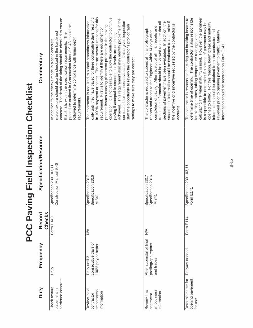
B-1
5
P
CC
Pavin
g F
ield
In
sp
ecti
on
Ch
ec
kli
st
Du
ty
Fre
qu
en
cy
R
ec
ord
S
pec
ific
ati
on
/Re
so
urc
e
Co
mm
en
tary
Ch
ec
ks
Che
ck t
extu
re
Daily
F
orm
E14
0
Sp
ecific
ation
230
1.0
3,
H
In a
dditio
n t
o t
he c
he
cks m
ade in
pla
stic c
on
cre
te,
pla
ce
men
t in
C
on
str
uctio
n M
an
ua
l 9
.40
ma
cro
textu
re s
ho
uld
als
o b
e c
he
cke
d in
th
e h
ard
ene
d
ha
rde
ne
d c
oncre
te
co
ncre
te.
Th
e d
ep
th o
f th
e t
inin
g s
ho
uld
be
ch
ecke
d t
o e
nsu
re
tha
t it f
alls
with
in t
he
sp
ecific
atio
n r
eq
uire
men
ts. T
he
pro
ced
ure
ou
tlin
ed
in
Co
nstr
uctio
n M
an
ua
l 9
.43 s
ho
uld
be
follo
we
d t
o d
ete
rmin
e c
om
plia
nce
with
tin
ing
dep
th
req
uire
men
ts.
Revie
w in
itia
l D
aily
un
til 3
N/A
S
pe
cific
ation
231
7
Th
e c
on
tracto
r is
re
quir
ed t
o s
ub
mit s
mo
oth
ness in
form
atio
n
co
ntr
acto
r co
nse
cu
tive
da
ys o
f
Sp
ecific
ation
231
6
da
ily u
ntil th
ey h
ave
pa
ve
d f
or
thre
e c
on
se
cu
tive
da
ys r
esu
ltin
g
sm
oo
thne
ss
10
0%
pa
y o
r be
tte
r
IM 3
41
in 1
00
% p
aym
en
t o
r be
tte
r.
Th
ere
are
se
ve
ral re
aso
ns fo
r th
is
info
rma
tio
n
re
qu
ire
men
t.
Fir
st is
to
id
entify
if
the
re a
re e
qu
ipm
en
t o
r
p
rocess issu
es c
ausin
g p
lacem
en
t p
roble
ms in
the
pa
vin
g
op
era
tio
n.
It
is n
ot
de
sir
ab
le t
o a
llow
th
e c
on
tra
cto
r to
co
ntin
ue
pa
vin
g if
accep
table
sm
oo
thness le
ve
ls a
re n
ot
be
ing
ach
ieve
d.
Th
is r
equ
irem
en
t a
lso
ma
y id
en
tify
pro
ble
ms in
the
co
ntr
acto
r's s
mo
oth
ness e
va
lua
tio
n.
It a
lso
giv
es in
spe
ctio
n
sta
ff th
e o
pp
ort
unity t
o r
evie
w th
e c
on
tracto
r's p
rofilo
gra
ph
se
ttin
gs t
o m
ake
su
re th
ey a
re c
orr
ect.
R
evie
w f
ina
l A
fte
r su
bm
itta
l o
f fin
al
N/A
S
pe
cific
ation
231
7
Th
e c
on
tracto
r is
re
quir
ed t
o s
ub
mit a
ll fin
al p
rofilo
gra
ph
co
ntr
acto
r p
rofilo
gra
ph
rep
ort
s
S
pe
cific
ation
231
6
rep
ort
s a
nd
tra
ce
s t
o th
e E
ng
ine
er
with
in 1
4 d
ays a
fte
r sm
oo
thne
ss
an
d t
races
IM
34
1
co
mp
letio
n o
f pa
vin
g. A
fte
r re
ce
ipt
of a
ll fina
l re
po
rts a
nd
info
rma
tio
n
tr
aces,
the
in
form
atio
n s
ho
uld
be
re
vie
we
d t
o e
nsu
re th
at
all
se
ctio
ns o
f p
ave
me
nt h
ave
bee
n e
va
lua
ted.
In a
dditio
n,
the
sm
oo
thne
ss info
rma
tion
sh
ould
be
evalu
ate
d t
o d
ete
rmin
e if
the
in
cen
tive
or
dis
ince
ntive
req
ue
ste
d b
y t
he
co
ntr
acto
r is
a
ccu
rate
.
Dete
rmin
e tim
e f
or
Daily
/as n
eed
ed
Fo
rm E
11
4
Sp
ecific
ation
230
1.0
3,
U
Th
e c
on
tra
cto
r is
re
sp
on
sib
le f
or
cu
rin
g a
nd
bre
akin
g b
ea
ms t
o
op
en
ing
pa
ve
men
t
F
orm
E14
1
de
term
ine t
ime
of
ope
nin
g.
The
con
tra
cto
r is
als
o r
esp
onsib
le
for
use
fo
r p
lacin
g p
rob
es,
takin
g te
mp
era
ture
re
ad
ing
s, a
nd
ca
lcu
latin
g T
TF
wh
en
ma
turi
ty is u
se
d.
Ho
we
ve
r, t
he
En
gin
ee
r
is
resp
on
sib
le t
o d
ete
rmin
e if a s
ection
of p
ave
men
t m
ay b
e
op
en
ed
to
tra
ffic
. F
or
this
re
aso
n,
bea
m b
reak a
nd
ma
turity
in
form
atio
n s
ho
uld
be
ob
tain
ed
fro
m t
he
con
tracto
r an
d
revie
we
d p
rio
r to
ope
nin
g p
ave
me
nt
to t
raff
ic.
Ma
turi
ty
info
rma
tio
n s
ho
uld
be
reco
rded
on
Fo
rm E
14
1.

B-1
6
PC
C P
avin
g F
ield
In
sp
ecti
on
Ch
ec
kli
st
Du
ty
Fre
qu
en
cy
R
ec
ord
S
pec
ific
ati
on
/Re
so
urc
e
Co
mm
en
tary
Ch
ec
ks
Che
ck lo
ng
itu
din
al
Sp
ot
ch
eck in
each
Fo
rm E
11
1
Sp
ecific
ation
230
1.0
3,
E
Ch
eck t
ie s
tee
l in
ha
rde
ne
d c
on
cre
te t
o e
nsu
re p
rop
er
tie
ste
el p
lacem
ent
da
y's
ru
n
R
oa
d S
tan
da
rd P
V-1
01
alig
nm
en
t an
d t
ha
t th
e c
orr
ect n
um
be
r o
f b
ars
are
inclu
de
d in
in h
ard
ene
d
Con
str
uctio
n M
an
ua
l 9
.26
an
d 9
.27
ea
ch p
ane
l (s
ee
Co
nstr
uctio
n M
an
ua
l 9
.27
).
Th
is c
heck is
co
ncre
te
im
po
rta
nt to
de
term
ine
th
at
the b
ars
are
ce
nte
red
acro
ss t
he
join
t, le
ve
l, a
nd
pe
rpe
nd
icu
lar
to c
en
terl
ine
. T
ie s
tee
l ch
ecks in
ha
rde
ne
d c
oncre
te a
re typ
ically
ma
de
usin
g a
su
rve
y p
in
fin
de
r.
Dete
rmin
e
On
ce
pe
r p
roje
ct
S
pe
cific
ation
230
1.0
4 a
nd
23
01
.05
Th
ere
are
se
ve
ral ste
ps to
take
In
eva
lua
tin
g p
ave
men
t p
ave
me
nt
thic
kn
ess
IM
34
6 a
nd
347
thic
kn
ess.
First,
ra
ndo
m c
ore
lo
ca
tio
ns f
or
ea
ch
se
ctio
n o
f
p
ave
me
nt,
as d
efine
d b
y I
M 3
46
, sh
ould
be
ob
tain
ed
fro
m
Dis
tric
t M
ate
ria
ls.
Th
en
th
e c
ore
loca
tio
ns s
ho
uld
be
ma
rke
d
on
th
e p
ave
me
nt.
Ta
kin
g o
f th
e c
ore
s m
ust
be w
itn
esse
d b
y
inspe
ctio
n s
taff
and
inspe
cto
rs m
ust
take
im
me
dia
te
po
sse
ssio
n o
f th
e c
ore
s a
fte
r re
mo
va
l fr
om
th
e p
ave
me
nt
by
the
co
ntr
acto
r.
Co
res s
ho
uld
th
en
be
me
asu
red
acco
rdin
g to
IM 3
47
an
d a
th
ickne
ss ind
ex d
ete
rmin
ed
fo
r e
ach
se
ctio
n o
f
p
ave
me
nt.
A
fte
r m
ea
su
rem
ent,
th
e c
ore
s s
ho
uld
be
de
live
red
to D
istr
ict M
ate
ria
ls f
or
assu
ran
ce
te
stin
g.

B-1
7
P
CC
Pavin
g F
ield
In
sp
ecti
on
Ch
ec
kli
st
Du
ty
Fre
qu
en
cy
R
ec
ord
S
pe
cif
ica
tio
n/R
es
ou
rce
C
om
me
nta
ry
Ch
ec
ks
Ge
nera
l
Che
ck t
raffic
co
ntr
ol W
hen
tra
ve
llin
g o
n t
he
E
ve
n t
ho
ug
h t
raff
ic c
on
trol ch
ecks a
re a
resp
on
sib
ility
of
the
p
roje
ct
co
ntr
acto
r, if
pro
ble
ms o
r d
eficie
ncie
s a
re o
bse
rve
d,
info
rm t
he
co
ntr
acto
r w
he
n t
he
ob
se
rva
tio
ns a
re m
ad
e s
o t
ha
t co
rre
ctio
ns
ca
n b
e m
ad
e in
a t
ime
ly m
an
ne
r.
Che
ck c
on
tracto
r's
As n
eed
ed
N/A
S
pe
cific
ation
252
8.1
, C
T
he
co
ntr
acto
r is
re
quir
ed t
o c
he
ck t
raffic
con
tro
l a
nd r
eco
rd
tra
ffic
co
ntr
ol d
aily
sig
nific
an
t in
form
ation
. I
t is
a g
oo
d p
ractice
to
re
vie
w t
he
dia
ry
co
ntr
acto
r's d
iary
occa
sio
na
lly to
ensu
re t
ha
t d
ocu
me
nta
tio
n is
be
ing r
eco
rded
as r
equ
ired
. F
or
insta
nce
, a
fte
r n
otin
g
da
ma
ge
d s
ign
ing
or
de
ficie
ncie
s in
th
e t
raff
ic c
on
trol d
evic
es o
r
se
tup
, re
vie
w t
he
da
ily d
iary
to e
nsu
re t
he
deficie
ncie
s a
nd
the
rem
edie
s a
re r
eco
rde
d.
Mo
nito
r th
e p
roje
ct
Daily
N
/A
Sp
ecific
ation
110
7.0
7,
E
Th
e c
on
tra
cto
r is
re
sp
on
sib
le f
or
co
ntr
olli
ng
fu
gitiv
e d
ust
on
th
e
for
fugitiv
e d
ust
p
roje
ct.
W
he
n d
ust
is b
ein
g g
en
era
ted
an
d le
avin
g t
he
pro
ject
site
, th
e c
on
tra
cto
r sh
ou
ld b
e r
em
ind
ed
of
the
ir r
esp
on
sib
ility
to
co
ntr
ol du
st a
nd
a r
equ
est
sh
ou
ld b
e m
ad
e to
take
me
asu
res
to d
o s
o. I
n u
rba
n a
reas, it is e
ve
n m
ore
critica
l th
at d
ust
be
co
ntr
olle
d a
s p
rop
ert
y o
wn
ers
will
be
mo
re s
ensitiv
e to
du
st
ge
ne
rate
d b
y t
he
pro
ject.
Mo
nito
r co
ntr
acto
r D
aily
N
/A
Con
str
uctio
n M
an
ua
l 2
.12
Th
e c
on
tracto
r is
re
quir
ed t
o s
ub
mit a
re
qu
est
for
hau
l ro
ad
ha
ul ro
ads
d
esig
na
tio
n fo
r ro
ad
s u
se
d to
ha
ul m
ate
rials
fo
r th
e p
roje
ct.
On
ce
desig
na
ted
as a
ha
ul ro
ute
, th
e c
on
tracto
r is
exp
ecte
d to
use
th
e h
au
l ro
ute
fo
r th
e d
esig
na
ted
pu
rpo
se
. T
he
co
ntr
acto
r's o
pe
ratio
ns s
ho
uld
be
ob
se
rve
d d
aily
to e
nsu
re t
ha
t
h
au
l tr
aff
ic is u
sin
g t
he
app
ropri
ate
, a
pp
rove
d h
au
l ro
ute
s.
Is
sue
When
no
nco
mp
lian
ce
Fo
rm 8
30
24
5
T
he
ow
ne
r is
oblig
ate
d to
no
tify
th
e c
on
tracto
r in
wri
tin
g w
hen
no
nco
mplia
nce
occu
rs
no
nco
mplia
nce o
ccu
rs.
Th
is is d
on
e u
sin
g F
orm
83
02
45
. n
otice
s
N
on
com
plia
nce
no
tices s
ho
uld
be
issu
ed
as q
uic
kly
as
pra
ctical a
fte
r ob
se
rva
tio
n o
f th
e n
on
com
plia
nce
to
giv
e t
he
co
ntr
acto
r a
mp
le t
ime
to t
ake
co
rrective
actio
n.
Th
e
no
nco
mplia
nce n
otice a
lso
pro
vid
es a
wri
tte
n r
eco
rd o
f
n
otificatio
n b
ein
g p
rovid
ed t
o th
e c
on
tracto
r.

B-1
8