Embed Size (px)
Citation preview

Pasco County Public Transportation
Transit Infrastructure
Guidelines Manual June 2005
[Park-and-Ride Section added December 2012]
I
Pasco County Public Transportation
Transit Infrastructure Guidelines Manual
Prepared for:
PASCO COUNTY METROPOLITAN PLANNING ORGANIZATION
7530 Little Road New Port Richey, FL 34654
Phone: (727) 847-8140 Fax: (727) 847-8084
PASCO COUNTY PUBLIC TRANSPORTATION (PCPT)
8620 Galen Wilson Boulevard Port Richey, FL 34668 Phone: (727) 834-3200
Fax: (727) 834-3344
Prepared by:
Tindale-Oliver & Associates, Inc. 1000 North Ashley Drive
Suite 400 Tampa, FL 33602
Phone: (813) 224-8862 Fax: (813) 226-2106
December 2005
[Park-and-Ride Section added December 2012]
II
Introduc on 4 Pasco County Public Transporta on 4 The PCPT Transit Infrastructure Guidelines Manual 4 The Purpose of the Manual 4 PCPT Service Map 5 Bus Stop Design Guidelines 6 Bus Stop Types 6 Standard Local Bus Stops 7 Major Local Bus Stops 8 Superstops/Transfer Centers 9 Summary Features for Exis ng Bus Stops 10 Summary of Features for Proposed/New Bus Stops 11 Bus Stop Placement 12 Bus Route Spacing 12 Bus Stop Spacing 13 Bus Stop Loca on 14 Bus Stop Loca on Considera ons 15 Bus Stop Dimensions 16 Bus Stop Layout 17 Minimum Road Side Clear Zone Requirements for Bus Stop Benches 18 Bus Shelter Style 19 Bus Shelter Design 20 Bus Shelter Placement 22 Bus Pull‐Out Bays 23 Bus Bulbs 24 Pavement Composi on 25 ADA Accessibility Guidelines 27 Bus Stop Infrastructure Elements 30 Bus Stop Signpost Design & Placement 31 Bench Placement 33 Curb Ramps 34 Informa on Kiosks/Displays 35 Bicycle Storage 36 Bus Design Guidelines 37 Bus Vehicle Dimensions 37 Bus Turning Template 38 Ver cal & Horizontal Clearance for Buses 39 Intersec on Design for Bus Turns 40 Bus Turnarounds 41
Table of Contents
III
Transit‐Oriented Development Guidelines 42 Characteris cs 42 Loca on of Parking 43 Building Loca on & Design 43 Clustered Development & Dense Street Corners 43 Land Use & TOD 44 Pedestrians, Bicycling, & Transit 45 Park‐and‐Ride Facili es 46 Introduc on 46 Exis ng Park‐and‐Ride Facili es in Pasco County 46 Key Park‐and‐Ride Facility Elements 47 Loca ng Park‐and‐Ride Facili es 48 Layout Design 49 Lot Size Es ma on 51 Lot Size Es ma on Using Lot Classifica on Table 51 Lot Size Es ma on Using Forecast/Model Data 52 Accessibility Compliance Overview 59 Accessibility Code Requirements 59 Accessible Routes 59 Surfaces and Sidewalks 60 Protruding Objects 60 Ramps and Curb Ramps 60 Parking Facili es 60 Bus Boarding and Aligh ng Areas 61 Park‐and‐Ride Signs 62 Bus Stop Signs 62 Other Signage 63 Other Parameters 63 Doors 63 Ameni es 64 References 65 Glossary 66
Table of Contents (con nued)
46
Park‐and‐Ride Facili es
Note: For effectively locating, planning, and designing
park‐and‐ride facilities in Pasco County, this chapter
should be used in concert with the Pasco County MPO
Conceptual Vision for Park and Ride Facilities
(December 2012), prepared and available separately.
Introduction
This portion of the Park‐and‐Ride Facilities chapter
provides the standards necessary to achieve
accessibility compliance. Issues concerning the
planning elements of park‐and‐ride facilities are
covered in the earlier section, providing conceptual
vision aspects for planning parking facilities in support
of public transit infrastructure. Additionally, the
newly‐released revision of the FDOT State Park‐and‐
Ride Guide (June 1, 2012) provides ample information
necessary to plan, implement, and manage park‐and‐
ride facilities. The State document, located at http://
www.dot.state.fl.us/transit/PagesFinalParkand
RideGuide 20120601.pdf, provides guidance on the
following elements:
Park‐and‐Ride Planning Process
Site Selec on
Demand and Facility Size Es ma on
Impact Assessments
Economic Analysis and Project Jus fica on
Conceptual Design Considera ons
Project Selec on, Funding, and Alloca on
Methods
Maintenance and Management
Promo on Marke ng
Inventorying, Evalua ng, and Repor ng on
Exis ng Facili es
Program Performance Evalua ons
Private Par cipa on
Use of this chapter of the PCPT Transit Infrastructure
Guidelines Manual and the State Park‐and‐Ride Guide
will provide adequate planning, design, and code
compliance information for the development of park‐
and‐ride facilities required to support the Pasco
County Public Transportation system.
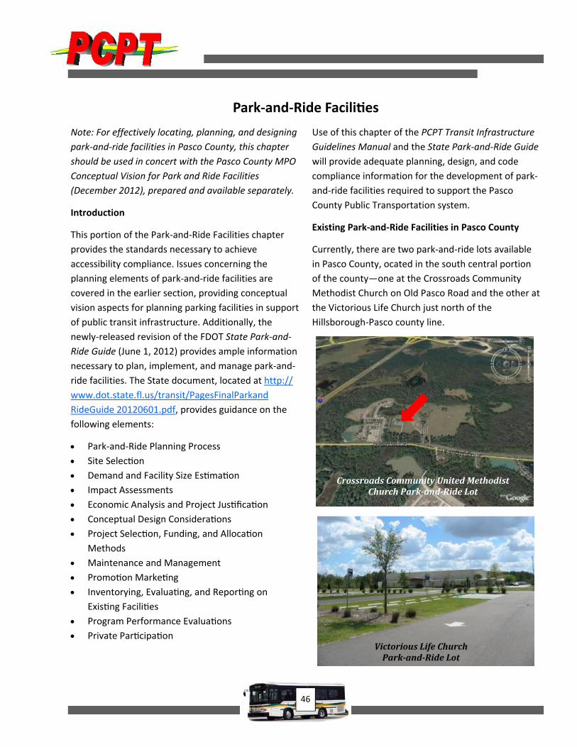
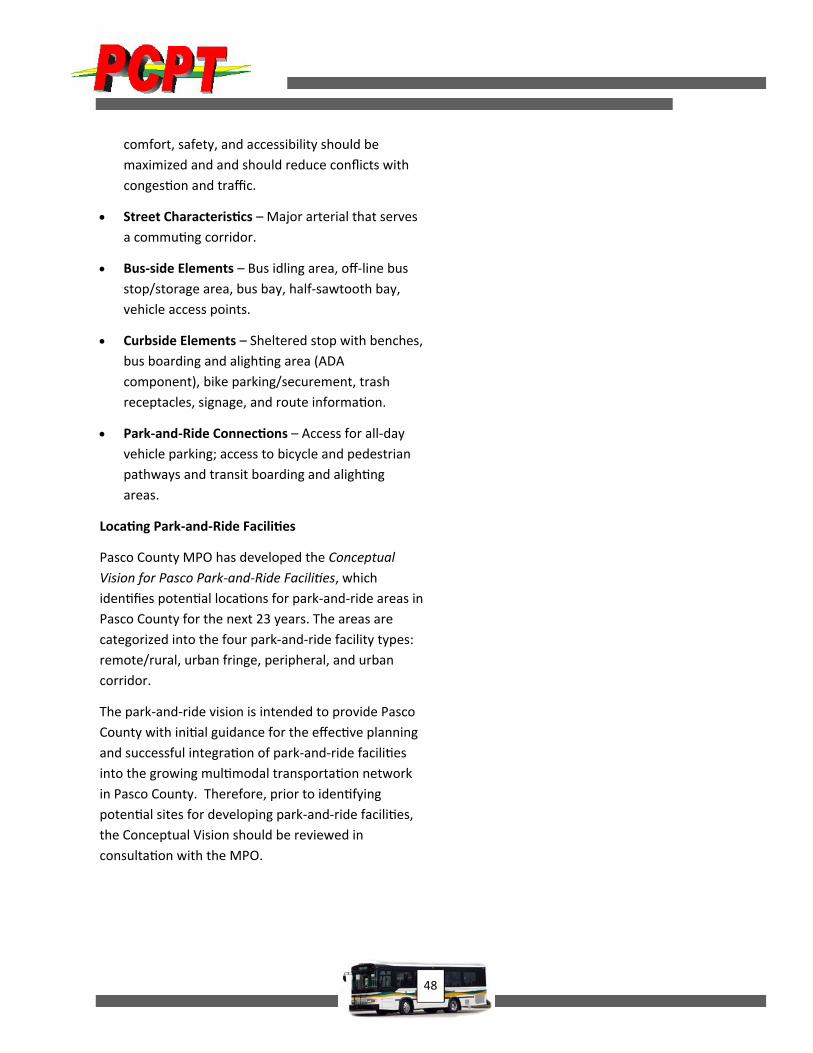
Existing Park‐and‐Ride Facilities in Pasco County
Currently, there are two park‐and‐ride lots available
in Pasco County, ocated in the south central portion
of the county—one at the Crossroads Community
Methodist Church on Old Pasco Road and the other at
the Victorious Life Church just north of the
Hillsborough‐Pasco county line.
VictoriousLifeChurchPark‐and‐RideLot
CrossroadsCommunityUnitedMethodistChurchPark‐and‐RideLot

47
Key Park‐and‐Ride Facility Elements
Types of park‐and‐ride lots include urban corridor,
urban fringe, peripheral , and remote. Urban lots are
usually served by express routes that collect transit
passengers near their homes in the suburbs and are
likely to be used for long‐haul trips or car/vanpooling.
Peripheral lots are generally located at the edges of
an activity center. Note that for the purpose of this
chapter, activity centers are described as major trip
generator/attractors such commercial hubs,
downtowns, collages/universities, office/retail
centers, etc. Urban and remote lots can sometimes be
joint‐use lots near developments such as libraries,
meeting halls, sports facilities, theaters, and
commercial land uses along major corridors that are
not generally used during the work day.
Refer to the Pasco County MPO Conceptual Vision for
Park and Ride Facilities for a detailed review of urban
corridor, urban fringe, peripheral, and remote park‐
and‐ride facilities.
Park‐and‐ride facilities that exclusively serve local
areas (transit routes) are generally smaller due to
relatively low demand and often require fewer
amenities. Facilities that serve commuter or express
routes are often larger and require shelters, bus idling
areas, and passenger drop‐off areas.
Automobiles should be able to access a park‐and‐ride
lot from collector or access roads intersecting
arterials, and bus turning movements should be in the
direction opposite incoming traffic. Lots should be
connected to multiple streets and ensure minimum
conflict with other traffic. Locating facilities on the
passenger side of larger traffic streams can avoid
conflicts with buses flowing in the opposite direction
when they attempt to enter the facility.
Area traffic patterns should be taken into
consideration, and adequate queuing space for
motorists to wait in cars before parking and
transferring to transit should be provided. Lots should
be located and designed such that passenger safety,
accessibility, and convenience are maximized.
Park‐and‐ride lots require all‐day parking for
commuters and should be located within 300 feet of
bus loading zones. The number of parking spaces is
determined on the basis of current and future
ridership; approximately 90 to 100 spaces per acre are
reasonable for such facilities. Designated spaces for
accessible parking must be located nearest to the bus
boarding and alighting areas and must include
accessible connections between the accessible
parking spaces and the bus loading areas and to
amenities throughout the facility.
Some key considerations for the installation of park‐
and‐ride facilities include the following.
Adjacent Land Use – Within exis ng
developments, ease of access to transit should be
provided in a car‐friendly manner, developed by
state or local governments or on private
proper es such as churches, schools, and
recrea on and community centers. This simply
means to build‐in connec ons, both pedestrian
and vehicular, as appropriate, between adjacent
developed facili es to facilitate use of the park‐
and‐ride facility.
Approximate Site Area – The site area connected
by mul ple streets should ensure minimal conflict
with other traffic with considera on of traffic
pa erns and commute pa erns. Enough space for
motorists to park cars based on the demand
needed for transferring to transit or van/
carpooling should be provided. Passenger
48
comfort, safety, and accessibility should be
maximized and and should reduce conflicts with
conges on and traffic.
Street Characteris cs – Major arterial that serves
a commu ng corridor.
Bus‐side Elements – Bus idling area, off‐line bus
stop/storage area, bus bay, half‐sawtooth bay,
vehicle access points.
Curbside Elements – Sheltered stop with benches,
bus boarding and aligh ng area (ADA
component), bike parking/securement, trash
receptacles, signage, and route informa on.
Park‐and‐Ride Connec ons – Access for all‐day
vehicle parking; access to bicycle and pedestrian
pathways and transit boarding and aligh ng
areas.
Loca ng Park‐and‐Ride Facili es
Pasco County MPO has developed the Conceptual
Vision for Pasco Park‐and‐Ride Facili es, which
iden fies poten al loca ons for park‐and‐ride areas in
Pasco County for the next 23 years. The areas are
categorized into the four park‐and‐ride facility types:
remote/rural, urban fringe, peripheral, and urban
corridor.
The park‐and‐ride vision is intended to provide Pasco
County with ini al guidance for the effec ve planning
and successful integra on of park‐and‐ride facili es
into the growing mul modal transporta on network
in Pasco County. Therefore, prior to iden fying
poten al sites for developing park‐and‐ride facili es,
the Conceptual Vision should be reviewed in
consulta on with the MPO.
49
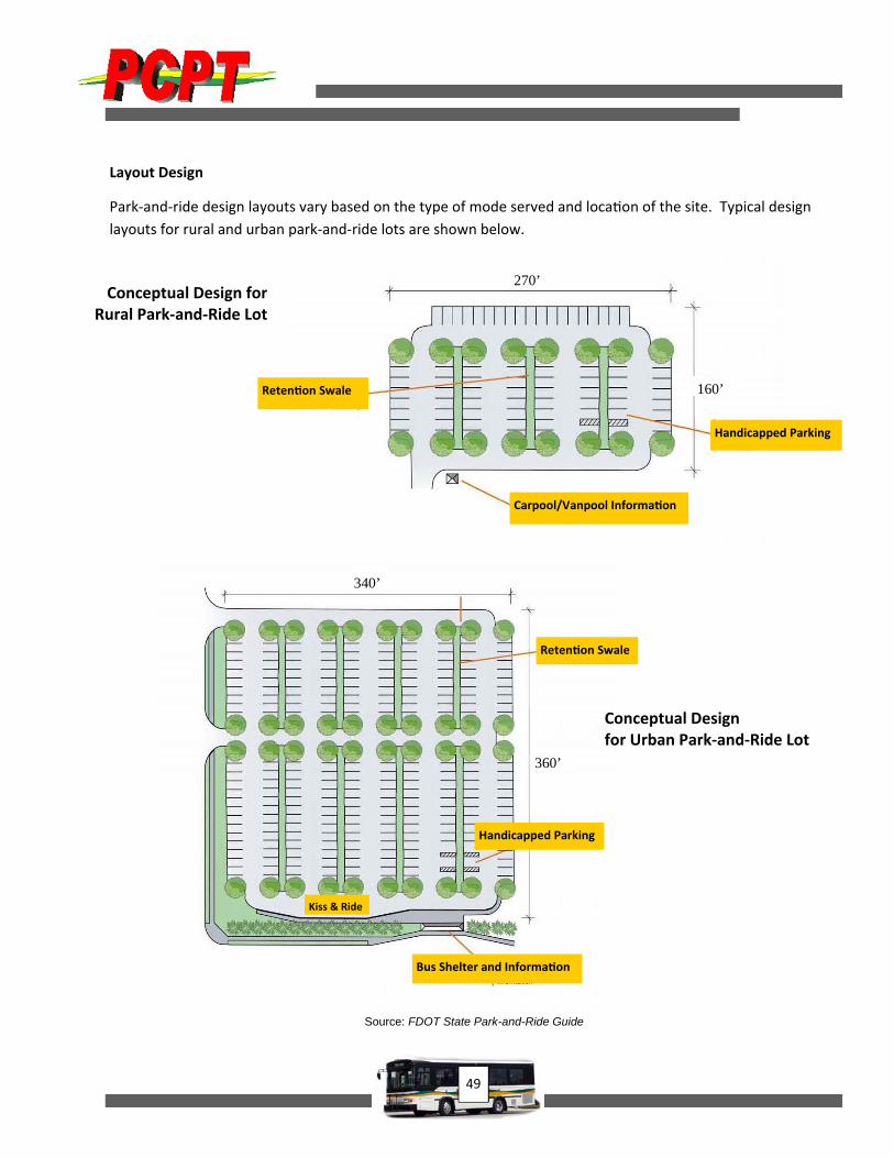
Layout Design
Park‐and‐ride design layouts vary based on the type of mode served and loca on of the site. Typical design
layouts for rural and urban park‐and‐ride lots are shown below.
Conceptual Design for Rural Park‐and‐Ride Lot
Reten on Swale
Handicapped Parking
Carpool/Vanpool Informa on
270’
160’
Bus Shelter and Informa on
Handicapped Parking
Reten on Swale
340’
360’
Kiss & Ride
Source: FDOT State Park-and-Ride Guide
Conceptual Design for Urban Park‐and‐Ride Lot
50
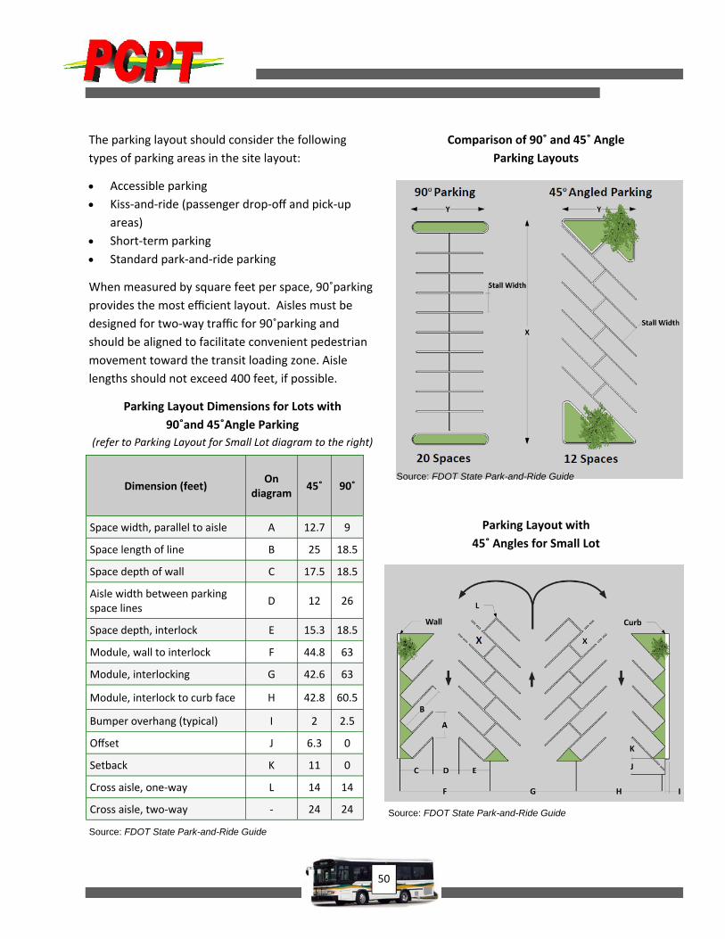
The parking layout should consider the following
types of parking areas in the site layout:
Accessible parking
Kiss‐and‐ride (passenger drop‐off and pick‐up
areas)
Short‐term parking
Standard park‐and‐ride parking
When measured by square feet per space, 90˚parking
provides the most efficient layout. Aisles must be
designed for two‐way traffic for 90˚parking and
should be aligned to facilitate convenient pedestrian
movement toward the transit loading zone. Aisle
lengths should not exceed 400 feet, if possible.
Parking Layout Dimensions for Lots with
90˚and 45˚Angle Parking
(refer to Parking Layout for Small Lot diagram to the right)
Comparison of 90˚ and 45˚ Angle
Parking Layouts
Parking Layout with
45˚ Angles for Small Lot
Dimension (feet) On
diagram 45˚ 90˚
Space width, parallel to aisle A 12.7 9
Space length of line B 25 18.5
Space depth of wall C 17.5 18.5
Aisle width between parking space lines
D 12 26
Space depth, interlock E 15.3 18.5
Module, wall to interlock F 44.8 63
Module, interlocking G 42.6 63
Module, interlock to curb face H 42.8 60.5
Bumper overhang (typical) I 2 2.5
Offset J 6.3 0
Setback K 11 0
Cross aisle, one‐way L 14 14
Cross aisle, two‐way ‐ 24 24
Source: FDOT State Park-and-Ride Guide
Source: FDOT State Park-and-Ride Guide
Source: FDOT State Park-and-Ride Guide
51
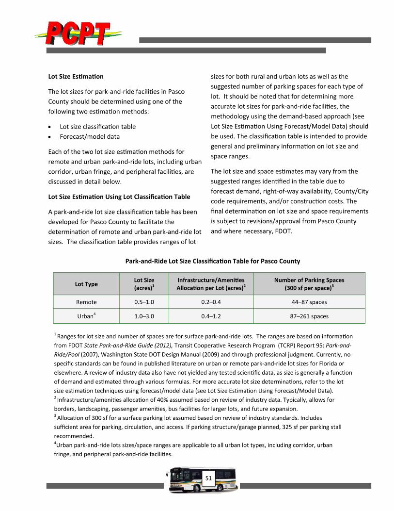
Park‐and‐Ride Lot Size Classifica on Table for Pasco County
1 Ranges for lot size and number of spaces are for surface park‐and‐ride lots. The ranges are based on informa on
from FDOT State Park‐and‐Ride Guide (2012), Transit Coopera ve Research Program (TCRP) Report 95: Park‐and‐
Ride/Pool (2007), Washington State DOT Design Manual (2009) and through professional judgment. Currently, no
specific standards can be found in published literature on urban or remote park‐and‐ride lot sizes for Florida or
elsewhere. A review of industry data also have not yielded any tested scien fic data, as size is generally a func on
of demand and es mated through various formulas. For more accurate lot size determina ons, refer to the lot
size es ma on techniques using forecast/model data (see Lot Size Es ma on Using Forecast/Model Data). 2 Infrastructure/ameni es alloca on of 40% assumed based on review of industry data. Typically, allows for
borders, landscaping, passenger ameni es, bus facili es for larger lots, and future expansion. 3 Alloca on of 300 sf for a surface parking lot assumed based on review of industry standards. Includes
sufficient area for parking, circula on, and access. If parking structure/garage planned, 325 sf per parking stall
recommended. 4Urban park‐and‐ride lots sizes/space ranges are applicable to all urban lot types, including corridor, urban
fringe, and peripheral park‐and‐ride facili es.
Lot Type Lot Size (acres)1
Infrastructure/Ameni es Alloca on per Lot (acres)2
Number of Parking Spaces (300 sf per space)3
Remote 0.5–1.0 0.2–0.4 44–87 spaces
Urban4 1.0–3.0 0.4–1.2 87–261 spaces
Lot Size Es ma on
The lot sizes for park‐and‐ride facili es in Pasco
County should be determined using one of the
following two es ma on methods:
Lot size classifica on table
Forecast/model data
Each of the two lot size es ma on methods for
remote and urban park‐and‐ride lots, including urban
corridor, urban fringe, and peripheral facili es, are
discussed in detail below.
Lot Size Es ma on Using Lot Classifica on Table
A park‐and‐ride lot size classifica on table has been
developed for Pasco County to facilitate the
determina on of remote and urban park‐and‐ride lot
sizes. The classifica on table provides ranges of lot
sizes for both rural and urban lots as well as the
suggested number of parking spaces for each type of
lot. It should be noted that for determining more
accurate lot sizes for park‐and‐ride facili es, the
methodology using the demand‐based approach (see
Lot Size Es ma on Using Forecast/Model Data) should
be used. The classifica on table is intended to provide
general and preliminary informa on on lot size and
space ranges.
The lot size and space es mates may vary from the
suggested ranges iden fied in the table due to
forecast demand, right‐of‐way availability, County/City
code requirements, and/or construc on costs. The
final determina on on lot size and space requirements
is subject to revisions/approval from Pasco County
and where necessary, FDOT.

52
Lot Size Es ma on Using Forecast/Model Data
Lot size es ma on for remote and urban lots,
including data needs and es ma on methodologies,
are discussed below.
The informa on provided here is from the FDOT State
Park‐and‐Ride Guide, which should be referred to for
more details on lot size es ma on.
Remote Lot Size Es ma on
Data needed:
Observa ons of actual informal parking
Popula on data at the trip origin
Employment data at the des na on end
The methodology for es ma ng lot size for a remote
facility includes coun ng exis ng informal parking
and adjus ng for growth and expected error. The
methodology and an example calcula on are
provided below. The example assumes design in five
years.
Remote Lot Size Es ma on – Methodology
Step 1: Iden fy parking ac vity surrounding the candidate site in Pasco County and count Actual
Informal Parking (AIP). AIP counts the parking occurring at informal loca ons serving a candidate site,
including on available right‐of‐way (ROW) or unused parking spaces at nearby private parking lots, etc.
This should be performed by an individual or study team familiar with the area, its commu ng pa erns,
and employment and ac vity centers a rac ng commuters. Iden fying the area in which to perform the
counts may be somewhat challenging due to the highly variable roadway configura ons, loca on of
commuter routes, and popula on.
Step 2: Select a design year and compute an appropriate growth factor. Compute the growth factor
based on projec ons of popula on within the service area of the lot (origin) and employment in the
urban area(s) the lot serves (des na on). A 2.5‐mile buffer around the facility can be used as lot service
area. (Research has shown that 50% of a park‐and‐ride facility’s demand is typically generated within a
2.5‐mile buffer area around the facility.) However, the service area may need to be expanded and
adjusted based on size and loca on of the popula on densi es. Suggested sources of popula on and
employment forecast data include Pasco County MPO’s LRTP or the University of Florida’s Florida
Sta s cal Abstract.
Step 3: Compute the design year parking demand. Mul ply the exis ng number of parked vehicles from
Step 1 by the growth factor computed in Step 2. This es mate of future design year parking demand may
need to be adjusted downward based on the experience that size es mates for remote lots tend to be
overstated. As construc on of a remote lot does not ensure its use by those observed to be parking at
informal loca ons nearby, the computed es mate of demand should account for this. This downward
adjustment should be based on local knowledge of public travel behavior and percep ons, poten al
effec veness of increased parking enforcement, and amount of ci zen requests and complaints
associated with facility provision.
53
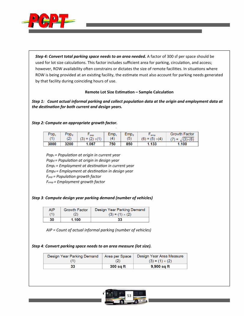
Step 4: Convert total parking space needs to an area needed. A factor of 300 sf per space should be
used for lot size calcula ons. This factor includes sufficient area for parking, circula on, and access;
however, ROW availability o en constrains or dictates the size of remote facili es. In situa ons where
ROW is being provided at an exis ng facility, the es mate must also account for parking needs generated
by that facility during coinciding hours of use.
Remote Lot Size Es ma on – Sample Calcula on
Step 1: Count actual informal parking and collect popula on data at the origin and employment data at the des na on for both current and design years. Step 2: Compute an appropriate growth factor.
Popc = Popula on at origin in current year Popd = Popula on at origin in design year Empc = Employment at des na on in current year Empd = Employment at des na on in design year Fpop = Popula on growth factor Femp = Employment growth factor
Step 3: Compute design year parking demand (number of vehicles)
AIP = Count of actual informal parking (number of vehicles)
Step 4: Convert parking space needs to an area measure (lot size).
54
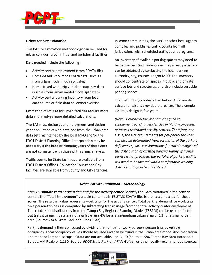
Urban Lot Size Es ma on
This lot size es ma on methodology can be used for
urban corridor, urban fringe, and peripheral facili es.
Data needed include the following:
Ac vity center employment (from ZDATA file)
Home‐based work mode share data (such as
from urban model mode split step)
Home‐based work trip vehicle occupancy data
(such as from urban model mode split step)
Ac vity center parking inventory from local
data source or field data collec on exercise
Es ma on of lot size for urban facili es require more
data and involves more detailed calcula ons.
The TAZ map, design year employment, and design
year popula on can be obtained from the urban area
data sets maintained by the local MPO and/or the
FDOT District Planning Office. Interpola on may be
necessary if the base or planning years of these data
are not consistent with those of the sizing analysis.
Traffic counts for State facili es are available from
FDOT District Offices. Counts for County and City
facili es are available from County and City agencies.
In some communi es, the MPO or other local agency
compiles and publishes traffic counts from all
jurisdic ons with scheduled traffic count programs.
An inventory of available parking spaces may need to
be performed. Such inventories may already exist and
can be obtained by contac ng the local parking
authority, city, county, and/or MPO. The inventory
should concentrate on spaces in public and private
surface lots and structures, and also include curbside
parking spaces.
The methodology is described below. An example
calcula on also is provided therea er. The example
assumes design in five years.
(Note: Peripheral facili es are designed to
supplement parking deficiencies in highly‐congested
or access‐restrained ac vity centers. Therefore, per
FDOT, the size requirements for peripheral facili es
can also be determined from es mates of the parking
deficiencies, with considera ons for transit usage and
the distribu on of exis ng parking supply. If transit
service is not provided, the peripheral parking facility
will need to be located within comfortable walking
distance of high ac vity centers.)
Urban Lot Size Es ma on – Methodology
Step 1: Es mate total parking demand for the ac vity center. Iden fy the TAZs contained in the ac vity center. The “Total Employment” variable contained in FSUTMS ZDATA files is then accumulated for these zones. The resul ng value represents work trips for the ac vity center. Total parking demand for work trips on a person‐trip basis is computed by subtrac ng transit usage from the total ac vity center employment. The mode split distribu ons from the Tampa Bay Regional Planning Model (TBRPM) can be used to factor out transit usage. If data are not available, use 4% for a large/medium urban area or 1% for a small urban area (Source: FDOT State Park‐and‐Ride Guide).
Parking demand is then computed by dividing the number of work‐purpose person trips by vehicle occupancy. Local occupancy values should be used and can be found in the urban area model documenta on and mode split model setups. If data are not available, use 1.110 (Source: 1996 Tampa Bay Area Household Survey, AM Peak) or 1.130 (Source: FDOT State Park‐and‐Ride Guide), or other locally‐recommended sources.
55
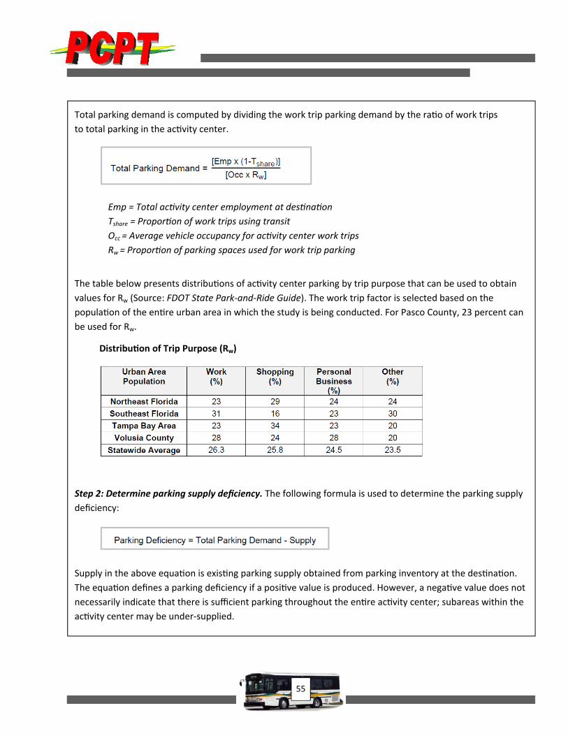
Total parking demand is computed by dividing the work trip parking demand by the ra o of work trips
to total parking in the ac vity center.
Emp = Total ac vity center employment at des na on
Tshare = Propor on of work trips using transit
Occ = Average vehicle occupancy for ac vity center work trips
Rw = Propor on of parking spaces used for work trip parking
The table below presents distribu ons of ac vity center parking by trip purpose that can be used to obtain
values for Rw (Source: FDOT State Park‐and‐Ride Guide). The work trip factor is selected based on the
popula on of the en re urban area in which the study is being conducted. For Pasco County, 23 percent can
be used for Rw.
Distribu on of Trip Purpose (Rw)
Step 2: Determine parking supply deficiency. The following formula is used to determine the parking supply
deficiency:
Supply in the above equa on is exis ng parking supply obtained from parking inventory at the des na on.
The equa on defines a parking deficiency if a posi ve value is produced. However, a nega ve value does not
necessarily indicate that there is sufficient parking throughout the en re ac vity center; subareas within the
ac vity center may be under‐supplied.
56
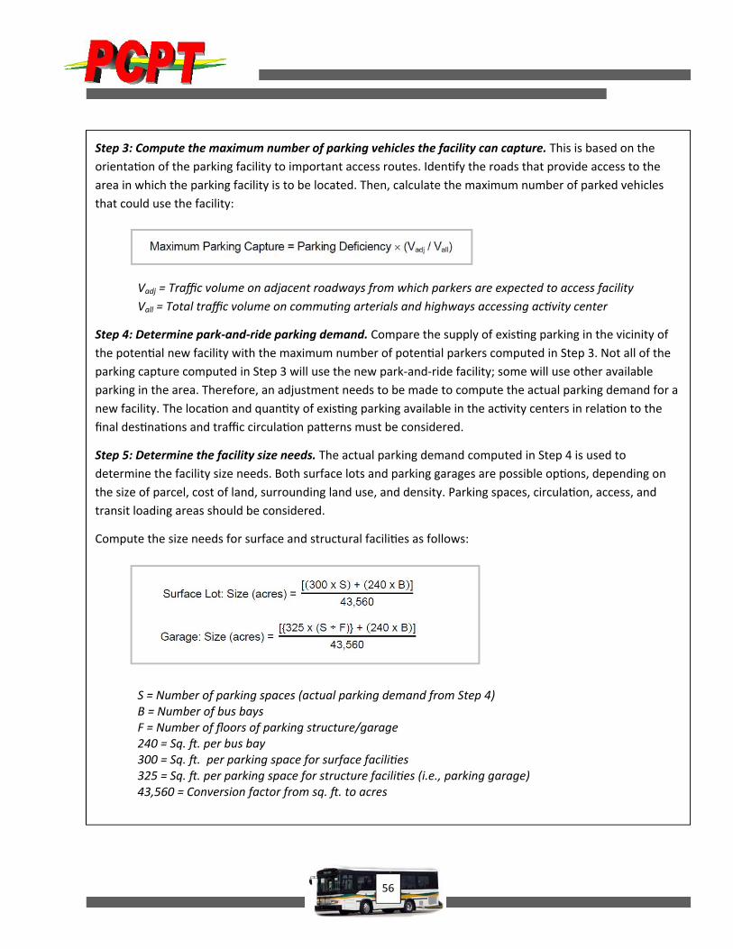
Step 3: Compute the maximum number of parking vehicles the facility can capture. This is based on the
orienta on of the parking facility to important access routes. Iden fy the roads that provide access to the
area in which the parking facility is to be located. Then, calculate the maximum number of parked vehicles
that could use the facility:
Vadj = Traffic volume on adjacent roadways from which parkers are expected to access facility
Vall = Total traffic volume on commu ng arterials and highways accessing ac vity center
Step 4: Determine park‐and‐ride parking demand. Compare the supply of exis ng parking in the vicinity of
the poten al new facility with the maximum number of poten al parkers computed in Step 3. Not all of the
parking capture computed in Step 3 will use the new park‐and‐ride facility; some will use other available
parking in the area. Therefore, an adjustment needs to be made to compute the actual parking demand for a
new facility. The loca on and quan ty of exis ng parking available in the ac vity centers in rela on to the
final des na ons and traffic circula on pa erns must be considered.
Step 5: Determine the facility size needs. The actual parking demand computed in Step 4 is used to
determine the facility size needs. Both surface lots and parking garages are possible op ons, depending on
the size of parcel, cost of land, surrounding land use, and density. Parking spaces, circula on, access, and
transit loading areas should be considered.
Compute the size needs for surface and structural facili es as follows:
S = Number of parking spaces (actual parking demand from Step 4) B = Number of bus bays F = Number of floors of parking structure/garage 240 = Sq. . per bus bay 300 = Sq. . per parking space for surface facili es 325 = Sq. . per parking space for structure facili es (i.e., parking garage) 43,560 = Conversion factor from sq. . to acres
57
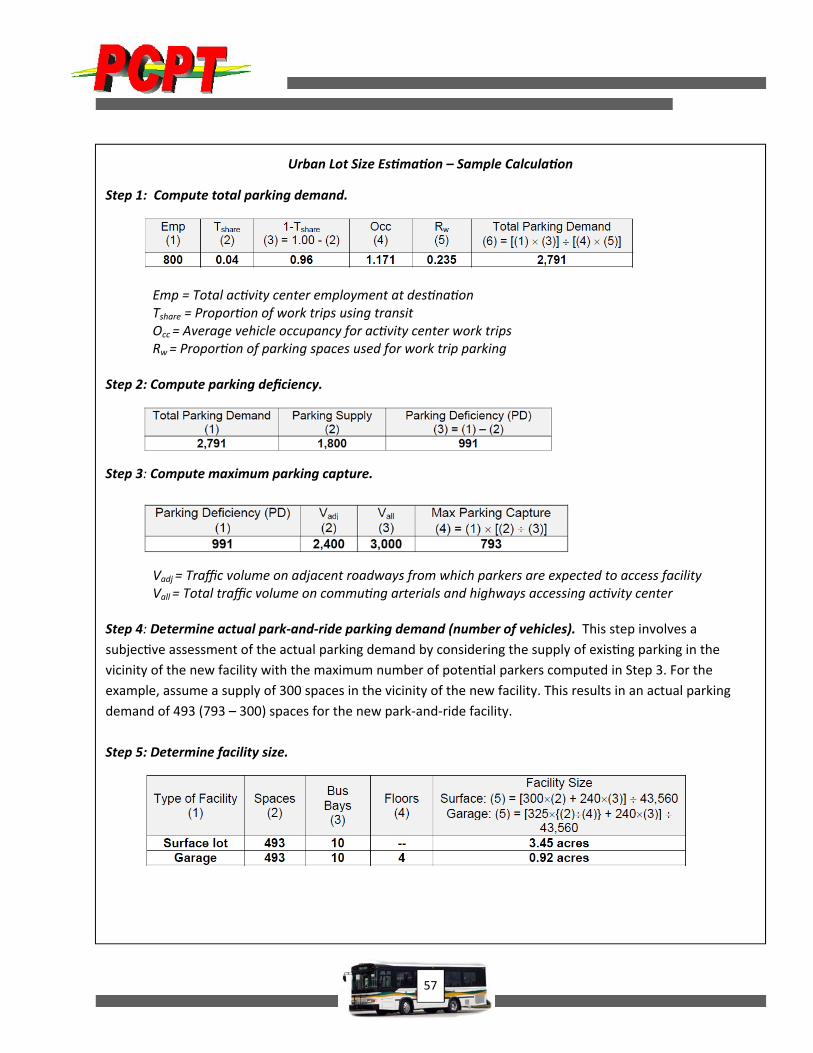
Urban Lot Size Es ma on – Sample Calcula on
Step 1: Compute total parking demand.
Emp = Total ac vity center employment at des na on Tshare = Propor on of work trips using transit Occ = Average vehicle occupancy for ac vity center work trips Rw = Propor on of parking spaces used for work trip parking
Step 2: Compute parking deficiency. Step 3: Compute maximum parking capture.
Vadj = Traffic volume on adjacent roadways from which parkers are expected to access facility Vall = Total traffic volume on commu ng arterials and highways accessing ac vity center
Step 4: Determine actual park‐and‐ride parking demand (number of vehicles). This step involves a
subjec ve assessment of the actual parking demand by considering the supply of exis ng parking in the
vicinity of the new facility with the maximum number of poten al parkers computed in Step 3. For the
example, assume a supply of 300 spaces in the vicinity of the new facility. This results in an actual parking
demand of 493 (793 – 300) spaces for the new park‐and‐ride facility.
Step 5: Determine facility size.
58
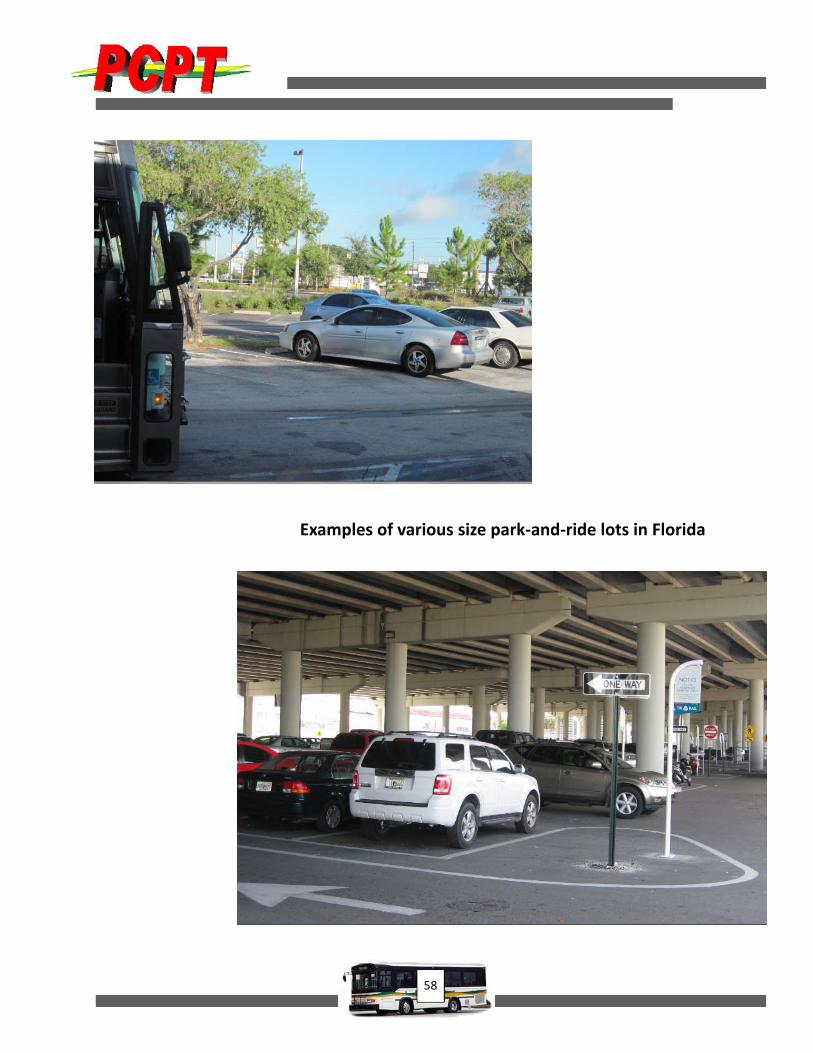
Examples of various size park‐and‐ride lots in Florida
59
Accessibility Compliance Overview Passengers generally reach bus boarding and alighting
areas from park‐and‐ride lots after parking their
automobiles. As the placement of park‐and‐ride lots
may vary from site to site due to various property or
financial limitations and physical conditions unique to
the site, accessibility for passengers from such lots to
the transit vehicle must be designed on a case‐by‐
case basis. In every such case, however, basic
minimum ADA standards must be followed in each
and every aspect of providing park‐and‐ride facilities
to ensure proper compliance with existing federal and
state regulations.
Federal accessibility requirements are provided by
the Americans with Disabilities Accessibility
Guidelines (ADAAG) as revised in 2004 and adopted
and enforced by the U.S. Department of
Transportation (DOT) on November 29, 2006.
Additionally, the U.S. Department of Justice (DOJ)
adopted the 2010 ADA Standards for Accessible
Design with full enforcement as of March 15, 2012.
State requirements are from the Florida Building
Code, Chapter 11 (Florida Accessibility Code). On
March 15, 2012, the State of Florida enacted a revised
set of accessibility standards titled the 2012 Florida
Accessibility Code (FAC) as an adjunct to the 2010
Florida Building Code. The 2012 FAC standards are, in
part, more stringent than are the DOT and DOJ
standards, particularly when applied to parking
requirements. The State frequently updates its
building code standards and generally issues
published updates to the codes every two years. The
2012 FAC rulemaking is a major update to the
accessibility code due to the federal adoption of the
2010 ADA Standards for Accessible Design. The
previous FAC had received certification by the DOJ of
its conformance to the ADAAG requirements, but
with the revision, recertification is necessary. The
2012 FAC has been developed in conformance with
the 2010 ADA Standards for Accessible Design and is
expected to receive recertification by DOJ.
With expectations of another revision of the ADAAG
standards considerably distant in time, another major
update of the FAC is also not expected. This chapter
includes the accessibility requirements enforced as
of the date of creation of this chapter covering park‐
and‐ride facilities; earlier chapters of this manual are
based on earlier code requirements.
Accessibility Code Requirements
Bus boarding and alighting (B&A) areas must meet
the minimum requirements of the ADAAG (mirrored
by FAC requirements). These requirements cover the
following potential elements of park‐and‐ride
facilities:
pedestrian pathways and access
bus boarding and aligh ng
passenger ameni es
informa on/communica on features
opera onal features
parking facili es
The broad categories listed above include the
following detailed accessibility parameters as applied
to park‐and‐ride facilities.
Accessible Routes
Must be 36 inches minimum wide con nuous
unobstructed path (note that FDOT standards
specify walkways must be 48 inches wide
minimum).
Must have a 32‐inch minimum width at
doorways.
Must have 60‐ × 60‐inch passing spaces at 200‐
foot intervals.
The running slope (direc on of travel) must be
equal to or less than 5 percent (>5% = ramp).

60
The cross slope (perpendicular to direc on of
travel) must be equal to or less than 2%.
Surfaces and Sidewalks
Surface must be firm, stable, and slip‐resistant
(wet or dry).
Changes in level between 1/4 and 1/2 inch
must be beveled at 1:2 slope.
Changes in level greater than 1/2 inch are not
allowed or must be ramped.
Gaps in gra ngs must be no greater than 1/2‐
inch wide, and openings must be aligned
perpendicular to travel.
Protruding Objects
Objects at 27–80 inches above grade must not
be more than a 4‐inch protrusion.
Post‐mounted objects must not be more than
a 12‐inch protrusion.
Overhead clearance must be equal to or
greater than 80 inches above the surface.
Ramps and Curb Ramps
The maximum ramp segment slope permi ed
is 1:12 (8.3%).
The maximum cross slope permi ed is 1:48
(2.08%).
Level landings must be provided at each 30
feet (1:12) or 40 feet (1:16) horizontal
projec on.
Landings must be no less than 60 inches long
and run the full width of the ramp segment.
Handrails must be provided on both sides of
the ramp (handrails are not required on curb
ramps).
Edge protec on must be provided on ramp
drop‐offs.
Change in direc on on ramps must be equal to
or greater than 60 × 60 inches.
Curb ramps must have detectable warning
material the full width of the ramp and either
the full length of the ramp or 24 inches from
the back edge of the curb.
Curb ramps must have a 36‐inch‐long landing
at the top of the slope.
Curb ramps must have detectable warning in
truncated domes with pa ern and
characteris cs defined by regula ons,
including contras ng color.
A detectable warning also is required at
landings and flush transi ons at street
crossings.
Parking Facilities
Accessible parking must be provided at public
access park‐and‐ride facili es.
The quan ty of accessible parking spaces must be
provided according to the following table.
FAC requires that each accessible parking space
be no less than 12 feet wide (ADAAG specifies an
8‐foot‐wide parking space).
Total Parking in Area/Lot or Structure
Required Minimum Number of Accessible Spaces
1–25 1
26–50 2
51–75 3
76–100 4
101–150 5
151–200 6
201–300 7
301–400 8
401–500 9
501–1000 2% of total
1001 and over 20 + 1 for each 100
over 1000
61
Each accessible parking space must have an
adjacent 60‐inch‐wide access aisle (two accessible
spaces can share an access aisle). The access aisle
must be striped diagonally to designate it as a
No Parking zone.
Accessible parking spaces and their access aisles
must be connected to the accessible route (44
inches wide per FAC) closest to the facility’s
accessible entrance and configured in a manner
so that users will not be compelled to travel
behind parked vehicles.
On‐street parallel parking spaces must be
located either at the beginning or end of a
block or adjacent to alley entrances.
Curb ramps must be located outside of the
disabled parking spaces and access aisles.
Parked vehicle overhangs must not reduce the
clear width of an accessible route.
Parking spaces and access aisles must be level,
with surface slopes not exceeding 1:48 (2.08%)
in all direc ons.
Per the FAC, each accessible parking space
must be prominently outlined with blue paint
and must be repainted as necessary so as to be
clearly dis nguishable as a parking space
designated for persons with disabili es and
must be posted with a permanent above‐grade
sign bearing the interna onal symbol for
accessibility, mee ng the requirements of
color and design approved by FDOT, Sec on
11‐4.30.7, and the cap on “Parking by Disabled
Permit Only.” Such sign erected a er October
1, 1996, must indicate the penalty for illegal
use of the space.
Van‐accessible parking spaces located within a
parking structure must have an addi onal sign
reading “Van Accessible” mounted below the
symbol of accessibility. Such signs must be
located so they cannot be obscured by a
vehicle parked in the space. A minimum of 1 in
every 6 accessible spaces or frac on thereof
must be iden fied as van accessible.
Van‐accessible spaces must provide a
minimum ver cal clearance of 114 inches at
accessible passenger loading zones and along
at least 1 vehicle access route to such areas
from site entrance(s) and exit(s). Non‐van‐
accessible spaces must provide a minimum
ver cal clearance of 98 inches at the space and
along at least one vehicle access route to the
site entrance.
Surfaces of parking spaces and access aisles
must be stable, firm, slip‐resistant, and located
on the same level (eleva on).
Bus Boarding and Alighting Areas
Must be on or connect to an accessible route.
Must have an accessible approach to the
boarding and aligh ng area and all provided
ameni es.
The clear area of the boarding and aligh ng
area must be equal to or no less than 60 inches
parallel and 96 inches perpendicular to the
curb or street/roadway edge and connected to
the accessible route.
The cross slope of the boarding and aligh ng area
(perpendicular to the curb) must be equal to or
less than 2%.
The running slope (parallel to the curb) of the
boarding and aligh ng area should match the
slope of roadway.
The boarding and aligh ng area must provide a
firm, stable, slip‐resistant surface.
The bus stop site must be chosen to provide the
greatest degree of accessibility prac cable.
Bus stop ameni es must be connected to an
accessible route and allow accessible

62
maneuvering space and be within a 48‐inch
maximum reach range of all opera ng controls.
If a shelter is provided, it must connect to the
accessible route and allow a minimum space of
30 × 48 inches fully within the shelter.
If a bench is included within a shelter, it must
allow minimum space of 30 × 48 inches res ng/
transfer space at one end of the bench.
Park‐and‐Ride Signs
Park‐and‐ride signs may be used to direct road users
to park‐and‐ride facilities. They also promote use of
the facility. They should be placed on all routes
providing access to a park‐and‐ride
lot and should be placed to
intercept users on their normal
paths and guide them directly to
the facility.
The signs should conform with the
applicable Manual on Uniform
Traffic Control Devices (MUTCD) and FDOT Design
Standards. The following standards and guidelines
are included in the most recent MUTCD:
The signs must contain the word message
“Park–Ride” and direc on informa on (arrow
or word message). However, they also may
contain the local transit pictograph and/or
carpool symbol.
If used, the local transit pictograph and/or
carpool symbol must be located in the top part
of the sign above the “Park–Ride” message. In
no case should the ver cal dimension of the
local transit pictograph and/or carpool symbol
exceed 18 inches. (If the func on of the
parking facility is to provide parking for
persons using public transporta on, the local
transit pictograph should be used on the guide
sign. If the func on of the parking facility is to
serve carpool riders, the carpool symbol should
be used on the guide sign. If the parking facility
serves both func ons, both the local transit
pictograph and carpool symbol should be
used.)
These signs must have a retroreflec ve white
legend and border on a rectangular green
background. The color of the local transit
pictograph must be selected by the local
transit authority. (To increase the target value
and contrast of the local transit pictograph,
and to allow the local transit pictograph to
retain its dis nc ve color and shape, the
pictograph may be included within a white
border or placed on a white background.)
The FDOT Traffic Engineering and Operations Office
should be contacted to ensure appropriate placement
distances for guide signs.
Signs should be considered at interstate or major
arterial highways to direct users to nearby facilities.
When feasible and applicable, using Variable Message
Signs (VMSs) may promote the lot and provide real‐
time information on the number of parking spaces
available and time until the next transit vehicle
leaves. However, VMS use requires approval by
Federal Highway Administration (FHWA) and/or
FDOT Traffic Engineering and Operations.
Bus Stop Signs
Proper signs at bus stops are an important element of
good transit service. Signs serve as a source of
information to patrons and operators regarding the
location of the bus stop and are excellent marketing
tools to promote transit use. For example, letter
styles, sign appearance, and color choice should be
unique to the transit system so that passengers can
readily identify bus stops.
63
Double‐sided signs that provide for visibility from
both direc ons and reflectorized signs for night‐
me visibility are preferred.
Bus stop signs should be placed at the loca on
where people board the front door of the bus.
The bus stop sign should show the area where
passengers should stand while wai ng for the
bus and serve as a guide for the bus operator
in posi oning the vehicle at the stop.
The bo om of the sign should be at least 7 feet
above ground level and should not be located
closer than 2 feet from the curb face.
Other Signage
Signs providing route designa ons, bus
numbers, des na ons, and access informa on
must be designed for use by transit riders with
vision impairments. In some cases, two sets of
signs may be needed to ensure visibility for
most users and to assist users with sight
limita ons. Route maps or metables are not
required at the stop, although such
informa on would be valuable to all
passengers.
Specific guidelines are given for these signs in
Sec on 703 of the ADAAG and must be
followed to ensure compliance.
Signage should follow the MUTCD, FDOT, and
local guidelines.
Other Parameters
Transit route informa on can be displayed on
shelters, in building lobbies, along developed
walkways, and in other appropriate areas to
provide accurate route and schedule
informa on to the public. PCPT bus stop
installa ons at park‐and‐ride facili es could
include a route schedule sign display mounted
to the bus stop sign post or on the shelter wall
when provided.
Landscape features can be used at transit
wai ng areas to increase passenger comfort
and to develop an a rac ve transit wai ng
area. Earth berming, trees, and other plan ngs
can be used to provide shade, act as
windbreaks, and offer an aesthe cally‐
appealing environment to transit users.
However, passenger security, as well as the
corner sight‐distance triangle, must be
considered when designing these features.
Doors
Doors at entrance, exits, and within facili es
must provide a minimum clear width opening
of 32 inches.
Maneuvering clearances in compliance with
ADAAG Sec on 404 must be provided at doors
to provide sufficient space for the
maneuverability of a wheelchair to gain egress.
If thresholds are provided at doorways, the
ver cal change in level must be no greater than
1/2 inch.
If doors are in series (as in a ves bule), the space
between two hinged or pivoted doors or gates
must provide a minimum of 48 inches plus the
width of the doors or gates that swing into the
space.
Handles, pulls, latches, locks, and other operable
parts on doors and gates must be located at 34
inches minimum and 48 inches maximum above
the finished floor or ground surface; they must
not require ght grasping, pinching, or twis ng of
the wrist to operate; and they must not require
more than 5 pounds of force to operate.
When a door is equipped with a closer and is
open to the 90˚ posi on and allowed to swing
shut to 12˚ from the latch, the me required to
close the door cannot exceed 5 seconds.

64
When a door is equipped with spring hinges and
is open to the 70˚ posi on and allowed to swing
shut to the latch, the me required to close the
door cannot exceed 1.5 seconds.
The force required to push or pull a door or gate
open can be no greater than 5 pounds.
Swinging door surfaces that are within 10 inches
above the finish floor or ground must be provided
with a smooth surface on the push side of the
door and cover the full width of the door.
Glazed panels within doors or adjacent to doors
that permit viewing through the panels must have
the bo om edge of at least 1 glazed panel located
no higher than 43 inches above the finished floor.
Where automa c or power‐assisted doors are
provided as a means of egress without standby
power, a clear break‐out opening must be
provided that is at least 32 inches wide for
emergency use.
Ameni es
Shelters, benches, leaning rails, trash receptacles,
bicycle racks, system informa on signage, or other
elements placed at park‐and‐ride facili es must be
placed in a manner to be fully accessible to people
with disabili es, as follows:
The amenity must be connected to an accessible
path that provides a direct connec on to the
boarding and aligh ng area and to other
ameni es provided at the site.
A clear 30‐ × 48‐inch space must be provided at
each amenity to allow for wheelchair access.
A clear unobstructed pathway width of 36 inches
minimum must be provided.
A maximum ver cal reach range of 48 inches
must be provided for ac va on of any controls on
use of objects such as pedestrian crossing signal
bu ons, brochures in informa on racks, switches,
on other control features that require patron
ac va on for use. Note that FDOT requires a
42‐inch reach range limit for pedestrian signal
control bu ons.
65
References
Brasco International, Inc., Detroit, MI. Slimline Series bus shelter schematics and images.
Ewing, Reid. Pedestrian and Transit‐Friendly Design. 1996.
Florida Department of Transportation. District 4 Transit Facilities Guidelines. April 2002.
Florida Department of Transportation. FDOT State Park‐and‐Ride Guide. June 2012.
Jacksonville Transportation Authority. JTA Mobility Access Program Handbook. September 2003.
Maryland Department of Transportation. Access by Design: Transit Role in Land Development. September
1988.
Metropolitan Transit Development Board. Designing For Transit. San Diego, California, July 1993.
Parsons Brinckerhoff. Geometric Design Guide for Transit Facilities on Highways and Streets—Phase I, Interim
Guide. July 2002.
Transit Cooperative Research Program. Report 19, Guidelines for the Location and Design of Bus Stops. 1996.
Transit Cooperative Research Program. Report 95, Park‐and‐Ride/Pool‐Traveler Response to Transportation
System Changes. 2004.
Tri‐County Metropolitan Transportation District of Oregon. Planning and Design for Transit Handbook. 1996.
U.S. Department of Transporta on. Manual on Uniform Traffic Control Devices. 2009.