Embed Size (px)
Citation preview
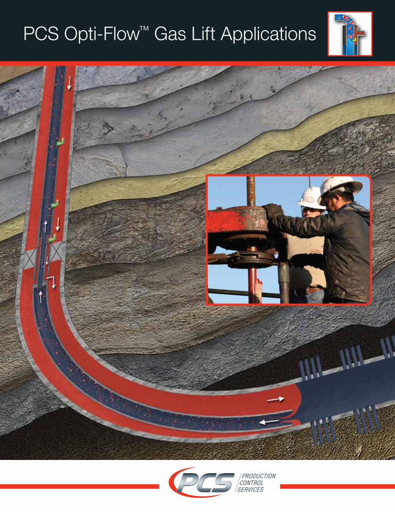
PCS Opti-Flow™ Gas Lift Applications
Optimizing production throughout the entire lifespan of the well.
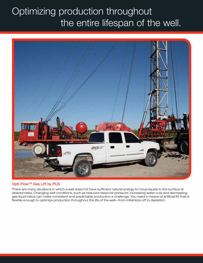
Opti-Flow™ Gas Lift by PCSThere are many situations in which a well does not have sufficient natural energy to move liquids to the surface at desired rates. Changing well conditions, such as reduced reservoir pressure, increasing water cuts and decreasing gas liquid ratios can make consistent and predictable production a challenge. You need a means of artificial lift that is flexible enough to optimize production throughout the life of the well—from initial kick-off to depletion.
When gas lift is the right choice.
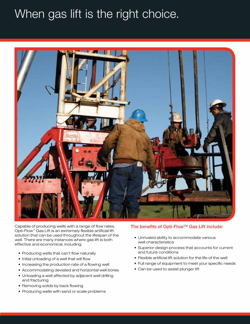
Capable of producing wells with a range of flow rates, Opti-Flow™ Gas Lift is an extremely flexible artificial lift solution that can be used throughout the lifespan of the well. There are many instances where gas lift is both effective and economical, including:
• Producing wells that can’t flow naturally
• Initial unloading of a well that will flow
• Increasing the production rate of a flowing well
• Accommodating deviated and horizontal well bores
• Unloading a well affected by adjacent well drilling and fracturing
• Removing solids by back flowing
• Producing wells with sand or scale problems
The benefits of Opti-Flow™ Gas Lift include: • Unrivaled ability to accommodate various
well characteristics
• Superior design process that accounts for current and future conditions
• Flexible artificial lift solution for the life of the well
• Full range of equipment to meet your specific needs
• Can be used to assist plunger lift
Gas Lift Types
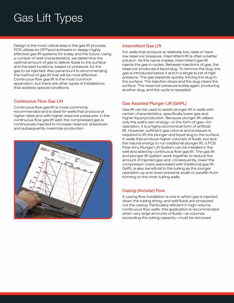
Design is the most critical step in the gas lift process. PCS utilizes its OPTIpod software to design highly effective gas lift systems for today and the future. Using a number of well characteristics, we determine the optimal amount of gas to deliver fluids to the surface and the best locations, based on pressure, for the gas to be injected. Also paramount is recommending the method of gas lift that will be most effective. Continuous flow gas lift is the most common application, but there are other types of installations that address special conditions.
Continuous Flow Gas Lift Continuous flow gas lift is most commonly recommended and is ideal for wells that produce at higher rates and with higher reservoir pressures. In the continuous flow gas lift well, the compressed gas is continuously injected to increase reservoir drawdown and subsequently maximize production.
Intermittent Gas Lift For wells that produce at relatively low rates or have low reservoir pressure, intermittent lift is often a better solution. As the name implies, intermittent gas lift injects the gas in cycles. Between injections of gas, the reservoir produces a liquid slug. To remove the slug, the gas is introduced below it and in a single burst of high pressure. The gas expands quickly, forcing the slug to the surface. The injection stops and the slug clears the surface. The reservoir pressure builds again, producing another slug, and the cycle is repeated.
Gas Assisted Plunger Lift (GAPL)Gas lift can be used to assist plunger lift in wells with certain characteristics, specifically lower gas and higher liquid production. Because plunger lift utilizes only the well’s own energy—in the form of gas—for operation, it is a highly economical form of artificial lift. However, sufficient gas volume and pressure is required to lift the plunger and liquid slug to the surface. In wells that produce higher volumes of fluids, but lack the natural energy to run traditional plunger lift, a PCS Flow-thru Plunger Lift System can be installed in the well and aided by continuous flow gas lift. The gas lift and plunger lift system work together to reduce the amount of injected gas and, consequently, lower the compressor costs associated with traditional gas lift. GAPL is also beneficial to the tubing as the plunger operation up and down prevents scale or paraffin from forming on the inner tubing walls.
Casing (Annular) Flow A casing flow installation is one in which gas is injected down the tubing string, and well fluids are produced out the casing. Particularly efficient in high-volume, continuous flow wells, this application is recommended when very large amounts of fluids—at volumes exceeding the tubing capacity—must be removed.
Gas Lift for Long, Perforated Intervals
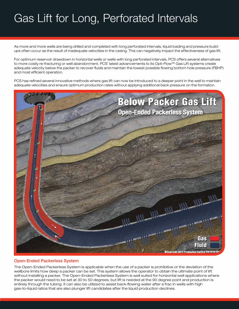
Open-Ended Packerless SystemThe Open-Ended Packerless System is applicable when the use of a packer is prohibitive or the deviation of the wellbore limits how deep a packer can be set. This system allows the operator to obtain the ultimate point of lift without installing a packer. The Open-Ended Packerless System is well suited for horizontal well applications where the packer would need to be set at 30 to 50 degrees, but lift is needed at the 90 degree point and production is entirely through the tubing. It can also be utilized to assist back-flowing water after a frac in wells with high gas-to-liquid ratios that are also plunger lift candidates after the liquid production declines.
As more and more wells are being drilled and completed with long perforated intervals, liquid loading and pressure build-ups often occur as the result of inadequate velocities in the casing. This can negatively impact the effectiveness of gas lift.
For optimum reservoir drawdown in horizontal wells or wells with long perforated intervals, PCS offers several alternatives to more costly re-fracturing or well abandonment. PCS’ latest advancements to its Opti-Flow™ Gas Lift systems create adequate velocity below the packer to recover fluids and maintain the lowest possible flowing bottom hole pressure (FBHP) and most efficient operation.
PCS has refined several innovative methods where gas lift can now be introduced to a deeper point in the well to maintain adequate velocities and ensure optimum production rates without applying additional back pressure on the formation.
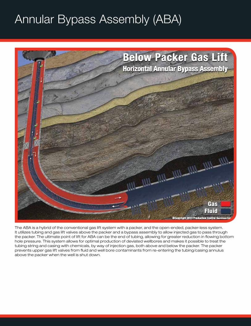
Annular Bypass Assembly (ABA)
The ABA is a hybrid of the conventional gas lift system with a packer, and the open-ended, packer-less system. It utilizes tubing and gas lift valves above the packer and a bypass assembly to allow injected gas to pass through the packer. The ultimate point of lift for ABA can be the end of tubing, allowing for greater reduction in flowing bottom hole pressure. This system allows for optimal production of deviated wellbores and makes it possible to treat the tubing string and casing with chemicals, by way of injection gas, both above and below the packer. The packer prevents upper gas lift valves from fluid and well bore contaminants from re-entering the tubing/casing annulus above the packer when the well is shut down.
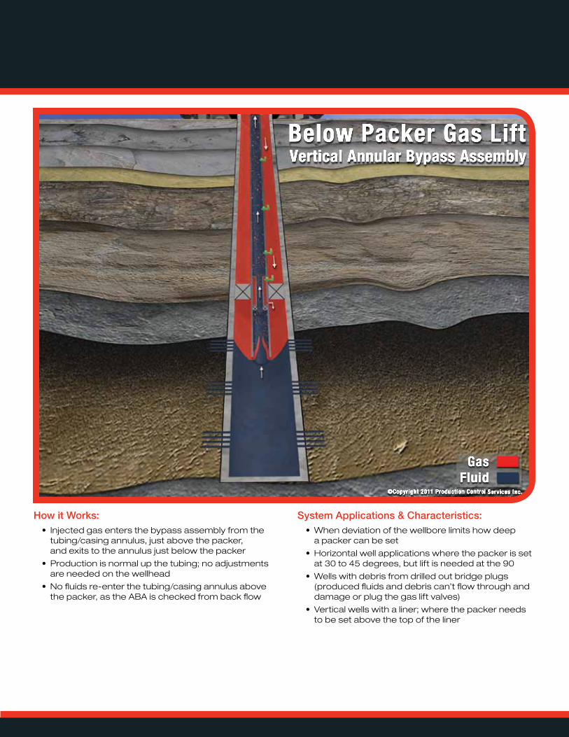
How it Works:• Injected gas enters the bypass assembly from the
tubing/casing annulus, just above the packer, and exits to the annulus just below the packer
• Production is normal up the tubing; no adjustments are needed on the wellhead
• No fluids re-enter the tubing/casing annulus above the packer, as the ABA is checked from back flow
System Applications & Characteristics:• When deviation of the wellbore limits how deep
a packer can be set
• Horizontal well applications where the packer is set at 30 to 45 degrees, but lift is needed at the 90
• Wells with debris from drilled out bridge plugs (produced fluids and debris can’t flow through and damage or plug the gas lift valves)
• Vertical wells with a liner; where the packer needs to be set above the top of the liner
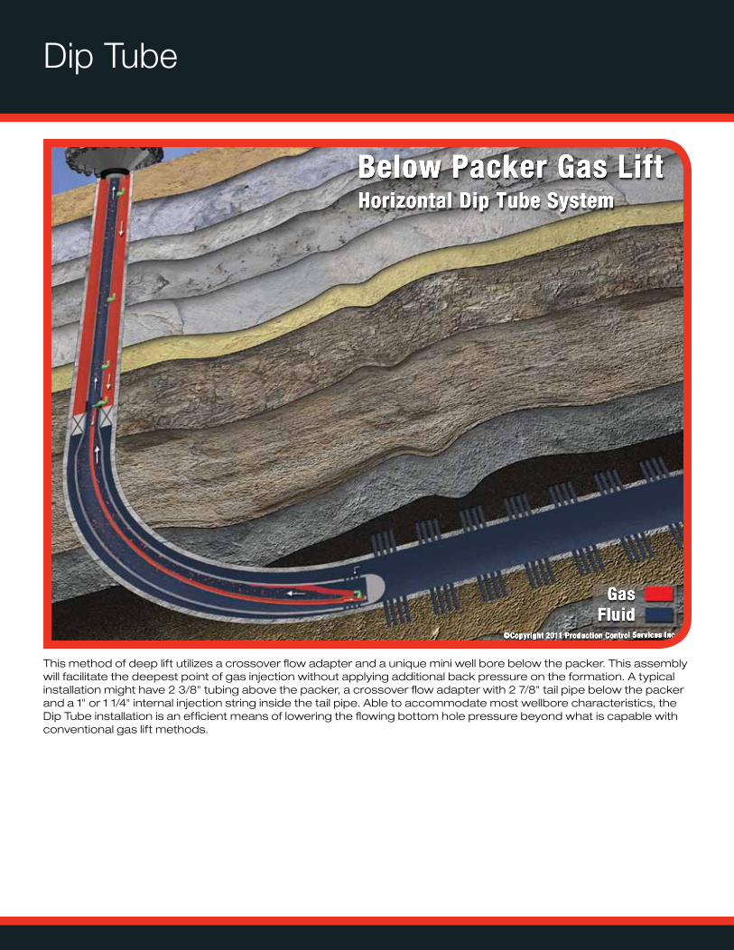
Dip Tube
This method of deep lift utilizes a crossover flow adapter and a unique mini well bore below the packer. This assembly will facilitate the deepest point of gas injection without applying additional back pressure on the formation. A typical installation might have 2 3/8" tubing above the packer, a crossover flow adapter with 2 7/8" tail pipe below the packer and a 1" or 1 1/4" internal injection string inside the tail pipe. Able to accommodate most wellbore characteristics, the Dip Tube installation is an efficient means of lowering the flowing bottom hole pressure beyond what is capable with conventional gas lift methods.
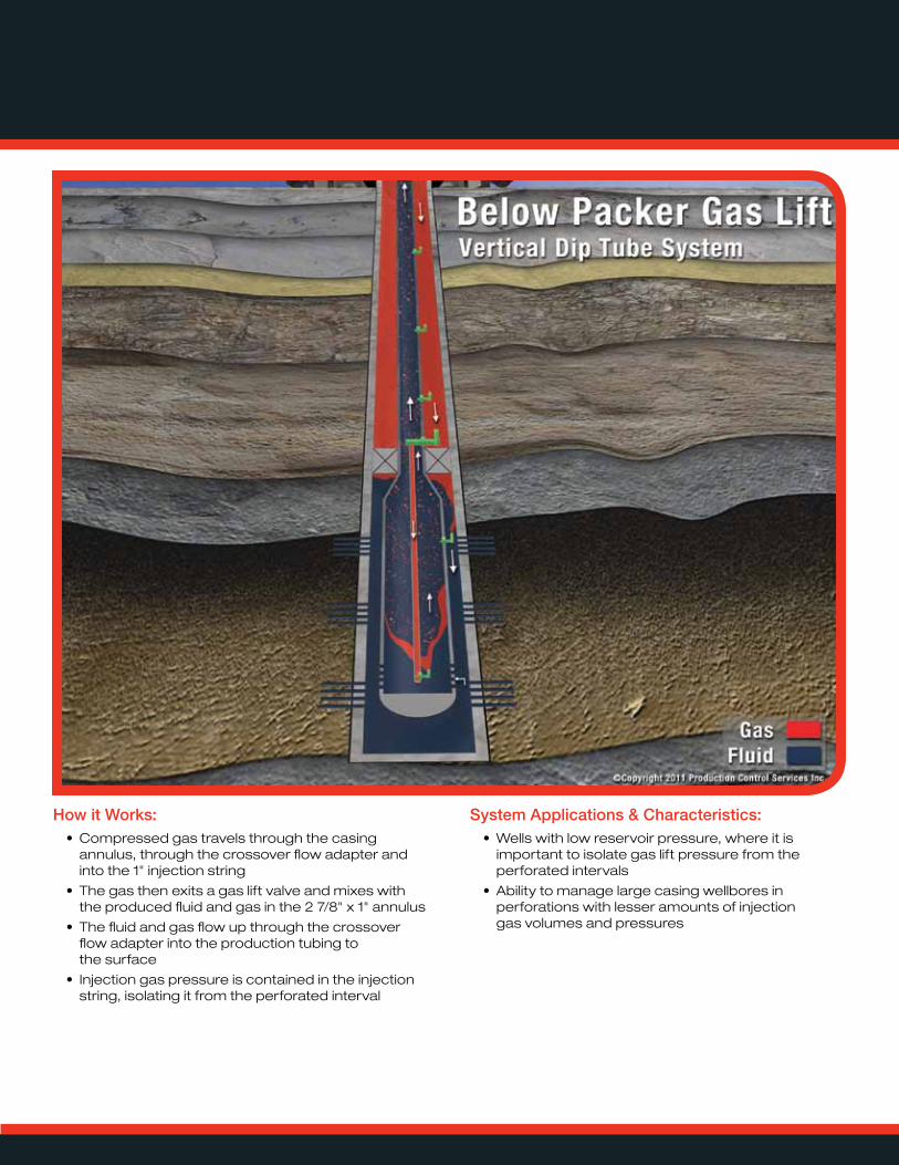
How it Works:• Compressed gas travels through the casing
annulus, through the crossover flow adapter and into the 1" injection string
• The gas then exits a gas lift valve and mixes with the produced fluid and gas in the 2 7/8" x 1" annulus
• The fluid and gas flow up through the crossover flow adapter into the production tubing to the surface
• Injection gas pressure is contained in the injection string, isolating it from the perforated interval
System Applications & Characteristics:• Wells with low reservoir pressure, where it is
important to isolate gas lift pressure from the perforated intervals
• Ability to manage large casing wellbores in perforations with lesser amounts of injection gas volumes and pressures
Enhanced Annular Velocity (EAV)
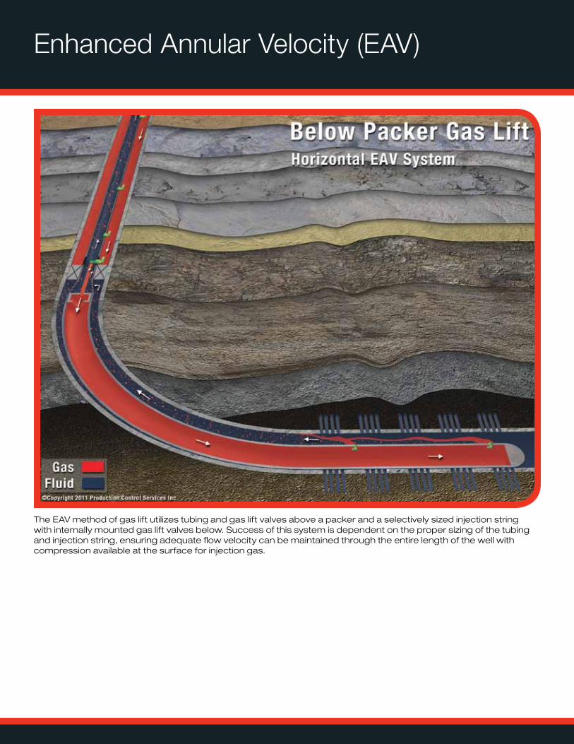
The EAV method of gas lift utilizes tubing and gas lift valves above a packer and a selectively sized injection string with internally mounted gas lift valves below. Success of this system is dependent on the proper sizing of the tubing and injection string, ensuring adequate flow velocity can be maintained through the entire length of the well with compression available at the surface for injection gas.
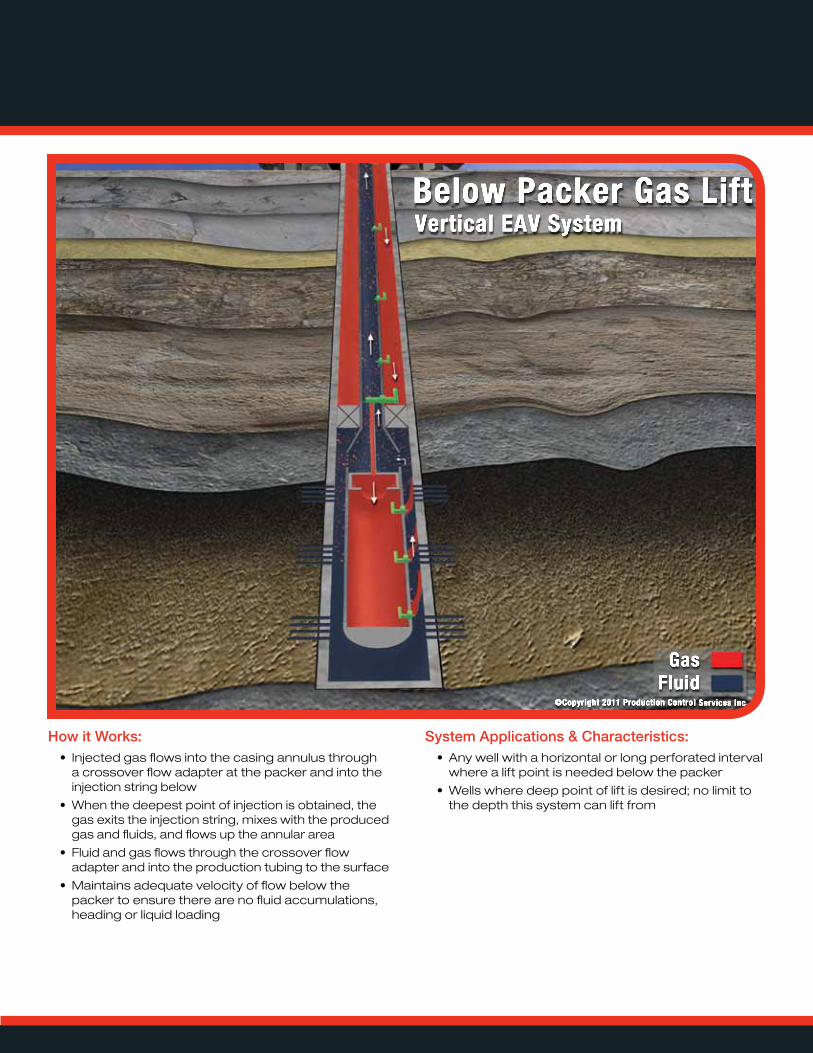
How it Works:• Injected gas flows into the casing annulus through
a crossover flow adapter at the packer and into the injection string below
• When the deepest point of injection is obtained, the gas exits the injection string, mixes with the produced gas and fluids, and flows up the annular area
• Fluid and gas flows through the crossover flow adapter and into the production tubing to the surface
• Maintains adequate velocity of flow below the packer to ensure there are no fluid accumulations, heading or liquid loading
System Applications & Characteristics:• Any well with a horizontal or long perforated interval
where a lift point is needed below the packer
• Wells where deep point of lift is desired; no limit to the depth this system can lift from
Marathon AVE
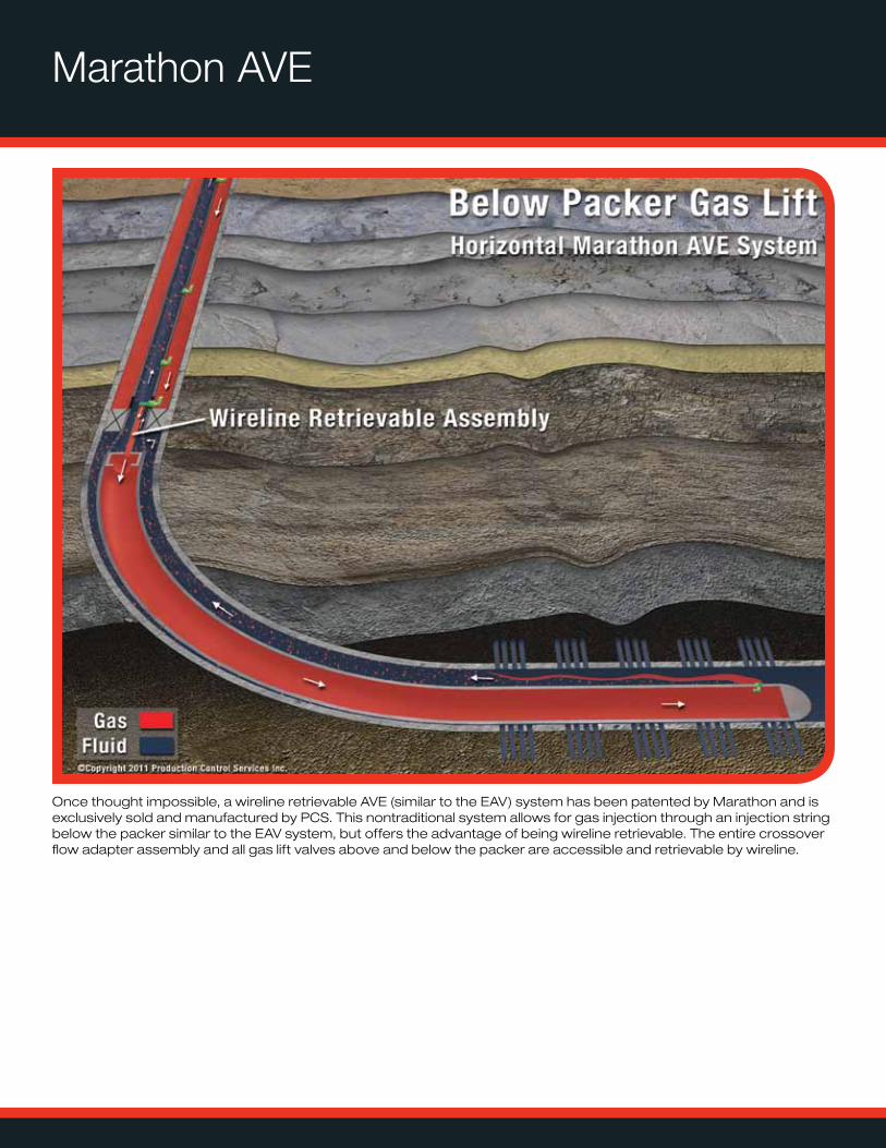
Once thought impossible, a wireline retrievable AVE (similar to the EAV) system has been patented by Marathon and is exclusively sold and manufactured by PCS. This nontraditional system allows for gas injection through an injection string below the packer similar to the EAV system, but offers the advantage of being wireline retrievable. The entire crossover flow adapter assembly and all gas lift valves above and below the packer are accessible and retrievable by wireline.
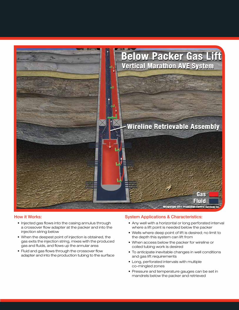
How it Works:• Injected gas flows into the casing annulus through
a crossover flow adapter at the packer and into the injection string below
• When the deepest point of injection is obtained, the gas exits the injection string, mixes with the produced gas and fluids, and flows up the annular area
• Fluid and gas flows through the crossover flow adapter and into the production tubing to the surface
System Applications & Characteristics:• Any well with a horizontal or long perforated interval
where a lift point is needed below the packer
• Wells where deep point of lift is desired; no limit to the depth this system can lift from
• When access below the packer for wireline or coiled tubing work is desired
• To anticipate inevitable changes in well conditions and gas lift requirements
• Long, perforated intervals with multiple co-mingled zones
• Pressure and temperature gauges can be set in mandrels below the packer and retrieved
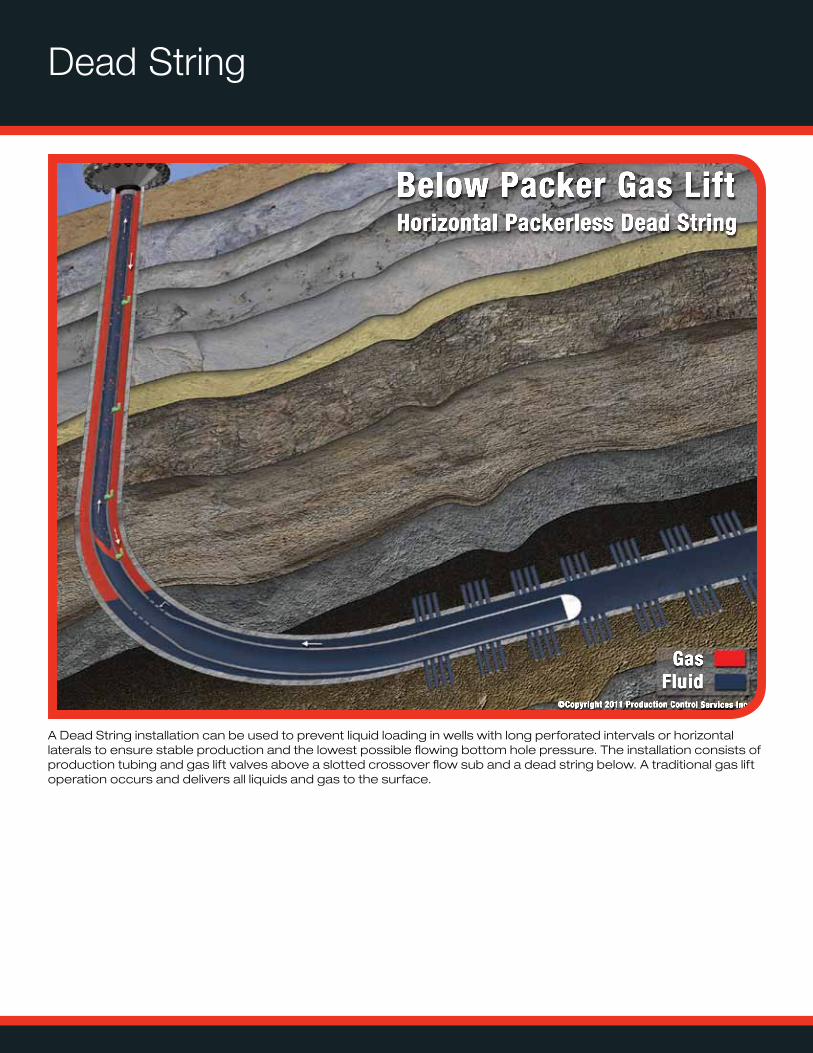
Dead String
A Dead String installation can be used to prevent liquid loading in wells with long perforated intervals or horizontal laterals to ensure stable production and the lowest possible flowing bottom hole pressure. The installation consists of production tubing and gas lift valves above a slotted crossover flow sub and a dead string below. A traditional gas lift operation occurs and delivers all liquids and gas to the surface.
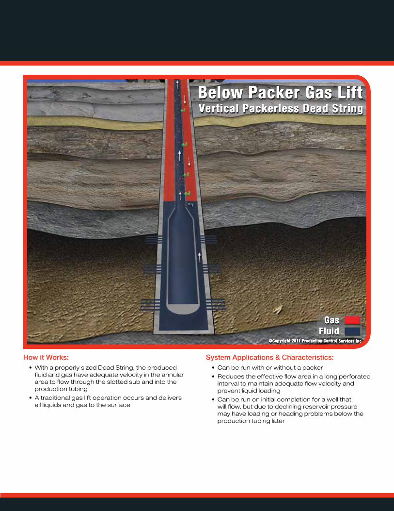
How it Works:• With a properly sized Dead String, the produced
fluid and gas have adequate velocity in the annular area to flow through the slotted sub and into the production tubing
• A traditional gas lift operation occurs and delivers all liquids and gas to the surface
System Applications & Characteristics:• Can be run with or without a packer
• Reduces the effective flow area in a long perforated interval to maintain adequate flow velocity and prevent liquid loading
• Can be run on initial completion for a well that will flow, but due to declining reservoir pressure may have loading or heading problems below the production tubing later
PLUNGER LIFT / GAS LIFT / NITROGEN GENERATION / AUTOMATION
www.pcslift.com
For more information, including a gas lift simulation, please visit www.pcslift.com.
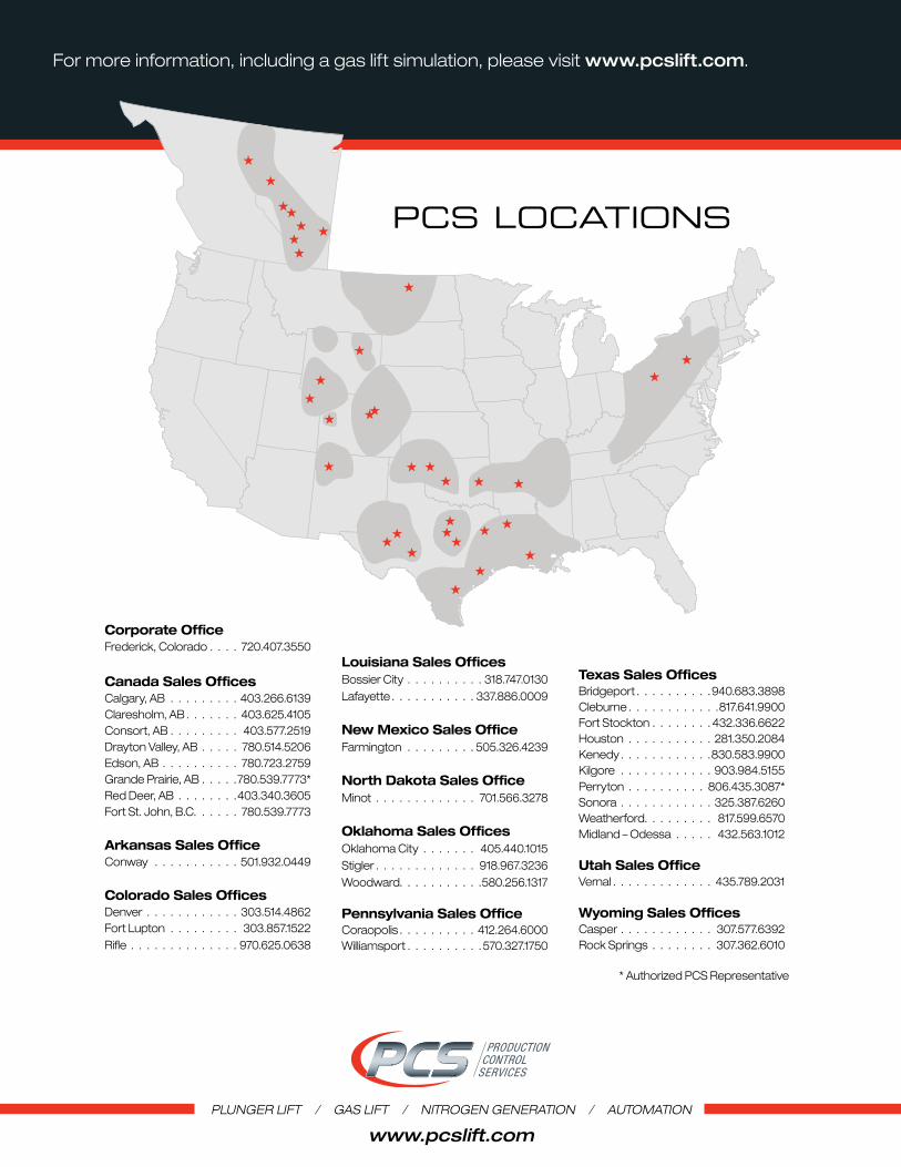
PCS LoCationS
* Authorized PCS Representative
Corporate OfficeFrederick, Colorado . . . . 720.407.3550
Canada Sales OfficesCalgary, AB . . . . . . . . . 403.266.6139Claresholm, AB . . . . . . . 403.625.4105Consort, AB . . . . . . . . . 403.577.2519Drayton Valley, AB . . . . . 780.514.5206Edson, AB . . . . . . . . . . 780.723.2759Grande Prairie, AB . . . . .780.539.7773*Red Deer, AB . . . . . . . .403.340.3605Fort St. John, B.C. . . . . . 780.539.7773
Arkansas Sales OfficeConway . . . . . . . . . . . 501.932.0449
Colorado Sales OfficesDenver . . . . . . . . . . . . 303.514.4862Fort Lupton . . . . . . . . . 303.857.1522Rifle . . . . . . . . . . . . . . 970.625.0638
Louisiana Sales OfficesBossier City . . . . . . . . . . 318.747.0130Lafayette . . . . . . . . . . . 337.886.0009
New Mexico Sales OfficeFarmington . . . . . . . . . 505.326.4239
North Dakota Sales OfficeMinot . . . . . . . . . . . . . 701.566.3278
Oklahoma Sales OfficesOklahoma City . . . . . . . 405.440.1015Stigler . . . . . . . . . . . . . 918.967.3236Woodward. . . . . . . . . . .580.256.1317
Pennsylvania Sales OfficeCoraopolis . . . . . . . . . . 412.264.6000 Williamsport . . . . . . . . . .570.327.1750
Texas Sales OfficesBridgeport . . . . . . . . . .940.683.3898Cleburne . . . . . . . . . . . .817.641.9900Fort Stockton . . . . . . . . 432.336.6622Houston . . . . . . . . . . . 281.350.2084Kenedy . . . . . . . . . . . .830.583.9900Kilgore . . . . . . . . . . . . 903.984.5155Perryton . . . . . . . . . . 806.435.3087*Sonora . . . . . . . . . . . . 325.387.6260Weatherford. . . . . . . . . 817.599.6570 Midland – Odessa . . . . . 432.563.1012
Utah Sales OfficeVernal . . . . . . . . . . . . . 435.789.2031
Wyoming Sales OfficesCasper . . . . . . . . . . . . 307.577.6392Rock Springs . . . . . . . . 307.362.6010