Embed Size (px)
Citation preview
PANdrive™ for Stepper Motors PANDRIVE™
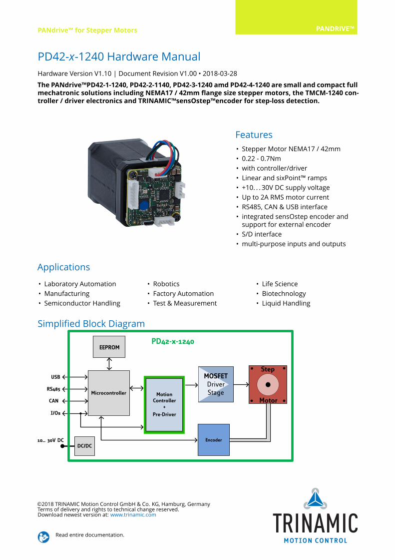
PD42-x-1240 Hardware ManualHardware Version V1.10 | Document Revision V1.00 • 2018-03-28The PANdrive™PD42-1-1240, PD42-2-1140, PD42-3-1240 amd PD42-4-1240 are small and compact fullmechatronic solutions including NEMA17 / 42mm flange size stepper motors, the TMCM-1240 con-troller / driver electronics and TRINAMIC™sensOstep™encoder for step-loss detection.
Features• Stepper Motor NEMA17 / 42mm• 0.22 - 0.7Nm• with controller/driver• Linear and sixPoint™ ramps• +10. . . 30V DC supply voltage• Up to 2A RMS motor current• RS485, CAN & USB interface• integrated sensOstep encoder andsupport for external encoder
• S/D interface• multi-purpose inputs and outputs
Applications• Laboratory Automation• Manufacturing• Semiconductor Handling
• Robotics• Factory Automation• Test & Measurement
• Life Science• Biotechnology• Liquid Handling
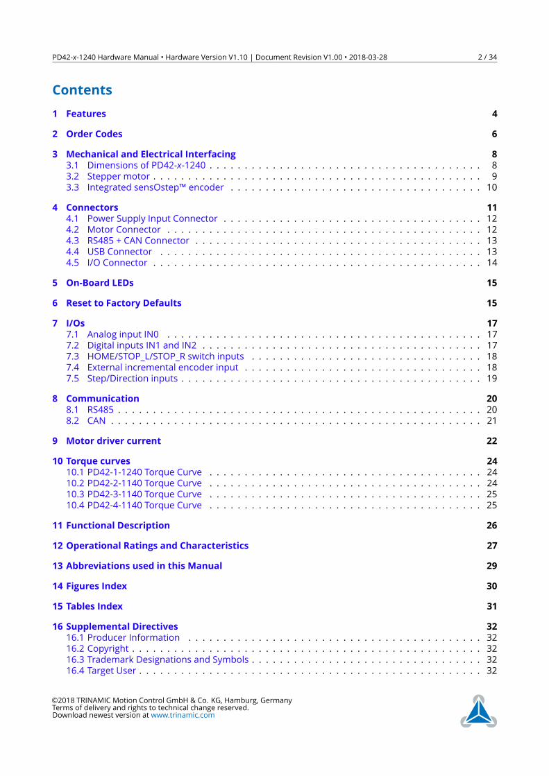
Simplified Block Diagram
10… 30V DC
Microcontroller
EEPROM
I/Os
Step
Motor
RS485
MOSFETDriverStage
Energy Efficient
DriverTMC262
MotionController
d
Pre-Driver
USB
CAN
DC/DCEncoder
PD42-x-1240
©2018 TRINAMIC Motion Control GmbH & Co. KG, Hamburg, GermanyTerms of delivery and rights to technical change reserved.Download newest version at: www.trinamic.com
Read entire documentation.
PD42-x-1240 Hardware Manual • Hardware Version V1.10 | Document Revision V1.00 • 2018-03-28 2 / 34
Contents1 Features 42 Order Codes 63 Mechanical and Electrical Interfacing 83.1 Dimensions of PD42-x-1240 . . . . . . . . . . . . . . . . . . . . . . . . . . . . . . . . . . . . . . . 83.2 Stepper motor . . . . . . . . . . . . . . . . . . . . . . . . . . . . . . . . . . . . . . . . . . . . . . . 93.3 Integrated sensOstep™ encoder . . . . . . . . . . . . . . . . . . . . . . . . . . . . . . . . . . . . 10
4 Connectors 114.1 Power Supply Input Connector . . . . . . . . . . . . . . . . . . . . . . . . . . . . . . . . . . . . . 124.2 Motor Connector . . . . . . . . . . . . . . . . . . . . . . . . . . . . . . . . . . . . . . . . . . . . . 124.3 RS485 + CAN Connector . . . . . . . . . . . . . . . . . . . . . . . . . . . . . . . . . . . . . . . . . 134.4 USB Connector . . . . . . . . . . . . . . . . . . . . . . . . . . . . . . . . . . . . . . . . . . . . . . 134.5 I/O Connector . . . . . . . . . . . . . . . . . . . . . . . . . . . . . . . . . . . . . . . . . . . . . . . 14
5 On-Board LEDs 156 Reset to Factory Defaults 157 I/Os 177.1 Analog input IN0 . . . . . . . . . . . . . . . . . . . . . . . . . . . . . . . . . . . . . . . . . . . . . 177.2 Digital inputs IN1 and IN2 . . . . . . . . . . . . . . . . . . . . . . . . . . . . . . . . . . . . . . . . 177.3 HOME/STOP_L/STOP_R switch inputs . . . . . . . . . . . . . . . . . . . . . . . . . . . . . . . . . 187.4 External incremental encoder input . . . . . . . . . . . . . . . . . . . . . . . . . . . . . . . . . . 187.5 Step/Direction inputs . . . . . . . . . . . . . . . . . . . . . . . . . . . . . . . . . . . . . . . . . . . 19
8 Communication 208.1 RS485 . . . . . . . . . . . . . . . . . . . . . . . . . . . . . . . . . . . . . . . . . . . . . . . . . . . . 208.2 CAN . . . . . . . . . . . . . . . . . . . . . . . . . . . . . . . . . . . . . . . . . . . . . . . . . . . . . 21
9 Motor driver current 2210 Torque curves 2410.1 PD42-1-1240 Torque Curve . . . . . . . . . . . . . . . . . . . . . . . . . . . . . . . . . . . . . . . 2410.2 PD42-2-1140 Torque Curve . . . . . . . . . . . . . . . . . . . . . . . . . . . . . . . . . . . . . . . 2410.3 PD42-3-1140 Torque Curve . . . . . . . . . . . . . . . . . . . . . . . . . . . . . . . . . . . . . . . 2510.4 PD42-4-1140 Torque Curve . . . . . . . . . . . . . . . . . . . . . . . . . . . . . . . . . . . . . . . 25
11 Functional Description 2612 Operational Ratings and Characteristics 2713 Abbreviations used in this Manual 2914 Figures Index 3015 Tables Index 3116 Supplemental Directives 3216.1 Producer Information . . . . . . . . . . . . . . . . . . . . . . . . . . . . . . . . . . . . . . . . . . 3216.2 Copyright . . . . . . . . . . . . . . . . . . . . . . . . . . . . . . . . . . . . . . . . . . . . . . . . . . 3216.3 Trademark Designations and Symbols . . . . . . . . . . . . . . . . . . . . . . . . . . . . . . . . . 3216.4 Target User . . . . . . . . . . . . . . . . . . . . . . . . . . . . . . . . . . . . . . . . . . . . . . . . . 32
©2018 TRINAMIC Motion Control GmbH & Co. KG, Hamburg, GermanyTerms of delivery and rights to technical change reserved.Download newest version at www.trinamic.com
PD42-x-1240 Hardware Manual • Hardware Version V1.10 | Document Revision V1.00 • 2018-03-28 3 / 34
16.5 Disclaimer: Life Support Systems . . . . . . . . . . . . . . . . . . . . . . . . . . . . . . . . . . . . 3216.6 Disclaimer: Intended Use . . . . . . . . . . . . . . . . . . . . . . . . . . . . . . . . . . . . . . . . 3216.7 Collateral Documents & Tools . . . . . . . . . . . . . . . . . . . . . . . . . . . . . . . . . . . . . . 33
17 Revision History 3417.1 Hardware Revision . . . . . . . . . . . . . . . . . . . . . . . . . . . . . . . . . . . . . . . . . . . . 3417.2 Document Revision . . . . . . . . . . . . . . . . . . . . . . . . . . . . . . . . . . . . . . . . . . . . 34
©2018 TRINAMIC Motion Control GmbH & Co. KG, Hamburg, GermanyTerms of delivery and rights to technical change reserved.Download newest version at www.trinamic.com
PD42-x-1240 Hardware Manual • Hardware Version V1.10 | Document Revision V1.00 • 2018-03-28 4 / 34
1 FeaturesThe PANdrive™PD42-1-1240, PD42-2-1140, PD42-3-1240 amd PD42-4-1240 are small and compact fullmechatronic solutions including NEMA17 / 42mm flange size stepper motors, the TMCM-1240 controller /driver electronics and TRINAMIC™sensOstep™encoder for step-loss detection. The four PANdrives includestepper motor with different lengths and different holding torques (PD42-1-1240: 0.22Nm, PD42-2-1240:0.36Nm, PD42-3-1240: 0.44Nm and PD42-4-1240: 0.7Nm) but, same electronics and encoder setup. ThePANdrives support both, stand-alone operation e.g. using the on-board I/Os together with the build-inTMCL scripting feature and remote operation using one of the available communication interfaces andeven a mixture of both.Motion Controller
• Motion profile calculation in real-time• On the fly alteration of motor parameters (e.g. position, velocity, acceleration)• Linear and unique sixPoint™ramp in hardware• Encoder interface and Reference / Stop switch inputs
Driver• Motor current: up to 2A RMS (2.2A RMS max. / 3.1A peak, programmable in software)• Supply voltage: +24V DC (+10. . . +30V DC)• 256 microsteps per fullstep• spreadCycle™highly dynamic current control chopper• stealthChop™for quiet operation and smooth motion• programmable Step/Dir interface for driver-only applications with microstep interpolation
Encoder• integrated sensOstep absolut position magnetic encoder (resolution: 1024 increments per rotation)for step-loss detection under all operating conditions and positioning supervision (accuracy: +/- 5encoder steps)
• support for external A/B incremental encoder in addition / as an alternative for the integratedencoder
• programmable encoder scaling and support for motor stop on encoder deviationInterfaces
• RS485 interface (up-to 1Mbit/s)• CAN interface (up-to 1Mbit/s)• USB 2.0 full speed (12Mbit/s) device interface (micro-USB connector)• Step/Dir input (optically isolated)• Left and Right STOP switch inputs (optically isolated, shared with Step/Dir inputs)• 2 general purpose digital inputs• Encoder input for incremental A/B encoder signals (shared with general purpose digital inputs)• 1 analog input (0..10V nom. input range)
©2018 TRINAMIC Motion Control GmbH & Co. KG, Hamburg, GermanyTerms of delivery and rights to technical change reserved.Download newest version at www.trinamic.com
PD42-x-1240 Hardware Manual • Hardware Version V1.10 | Document Revision V1.00 • 2018-03-28 5 / 34
• HOME switch input (shared with analog input)Software
• TMCL™ remote (direct mode) and standalone operation (memory for up to 1024 TMCL™ commands),fully supported by TMCL-IDE (PC based integrated development environment). Please see PD42-x-1240 TMCL firmware manual for more details
• CANopen firmware with CANopen standard protocol stack for the CAN interface. Please see PD42-x-1240 CANopen firmware manual for more details.
©2018 TRINAMIC Motion Control GmbH & Co. KG, Hamburg, GermanyTerms of delivery and rights to technical change reserved.Download newest version at www.trinamic.com
PD42-x-1240 Hardware Manual • Hardware Version V1.10 | Document Revision V1.00 • 2018-03-28 6 / 34
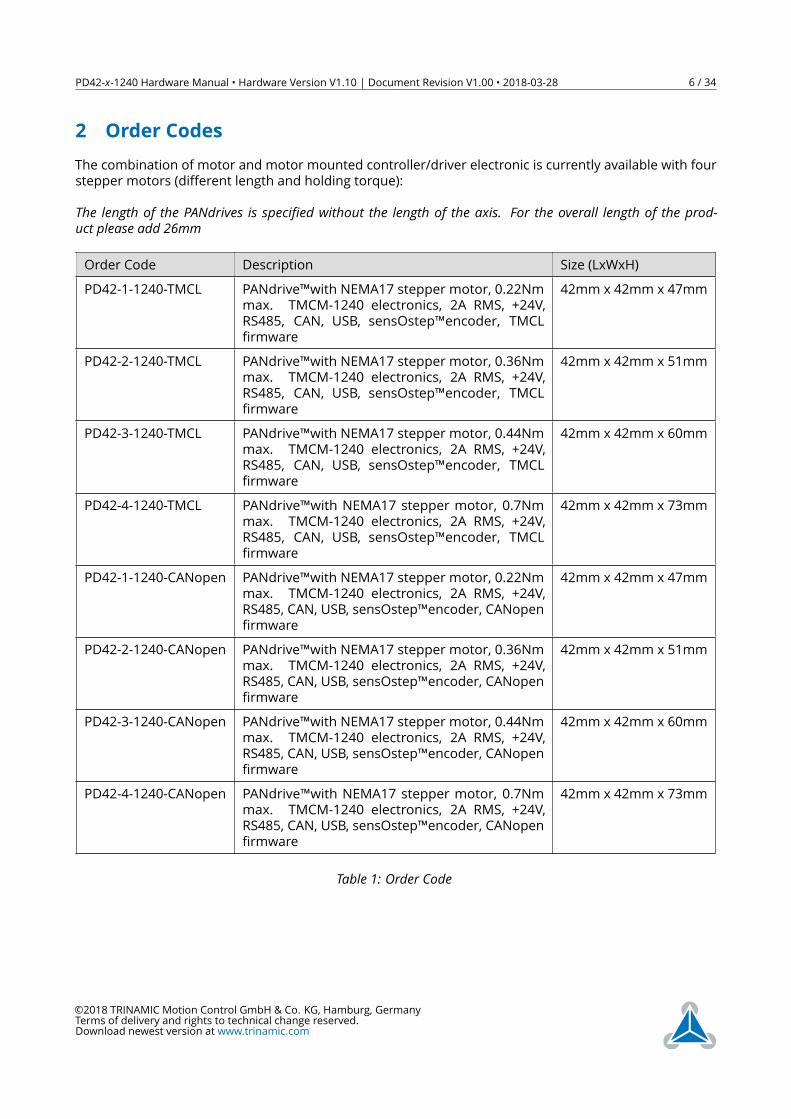
2 Order CodesThe combination of motor and motor mounted controller/driver electronic is currently available with fourstepper motors (different length and holding torque):The length of the PANdrives is specified without the length of the axis. For the overall length of the prod-uct please add 26mm
Order Code Description Size (LxWxH)PD42-1-1240-TMCL PANdrive™with NEMA17 stepper motor, 0.22Nm
max. TMCM-1240 electronics, 2A RMS, +24V,RS485, CAN, USB, sensOstep™encoder, TMCLfirmware
42mm x 42mm x 47mm
PD42-2-1240-TMCL PANdrive™with NEMA17 stepper motor, 0.36Nmmax. TMCM-1240 electronics, 2A RMS, +24V,RS485, CAN, USB, sensOstep™encoder, TMCLfirmware
42mm x 42mm x 51mm
PD42-3-1240-TMCL PANdrive™with NEMA17 stepper motor, 0.44Nmmax. TMCM-1240 electronics, 2A RMS, +24V,RS485, CAN, USB, sensOstep™encoder, TMCLfirmware
42mm x 42mm x 60mm
PD42-4-1240-TMCL PANdrive™with NEMA17 stepper motor, 0.7Nmmax. TMCM-1240 electronics, 2A RMS, +24V,RS485, CAN, USB, sensOstep™encoder, TMCLfirmware
42mm x 42mm x 73mm
PD42-1-1240-CANopen PANdrive™with NEMA17 stepper motor, 0.22Nmmax. TMCM-1240 electronics, 2A RMS, +24V,RS485, CAN, USB, sensOstep™encoder, CANopenfirmware
42mm x 42mm x 47mm
PD42-2-1240-CANopen PANdrive™with NEMA17 stepper motor, 0.36Nmmax. TMCM-1240 electronics, 2A RMS, +24V,RS485, CAN, USB, sensOstep™encoder, CANopenfirmware
42mm x 42mm x 51mm
PD42-3-1240-CANopen PANdrive™with NEMA17 stepper motor, 0.44Nmmax. TMCM-1240 electronics, 2A RMS, +24V,RS485, CAN, USB, sensOstep™encoder, CANopenfirmware
42mm x 42mm x 60mm
PD42-4-1240-CANopen PANdrive™with NEMA17 stepper motor, 0.7Nmmax. TMCM-1240 electronics, 2A RMS, +24V,RS485, CAN, USB, sensOstep™encoder, CANopenfirmware
42mm x 42mm x 73mm
Table 1: Order Code
©2018 TRINAMIC Motion Control GmbH & Co. KG, Hamburg, GermanyTerms of delivery and rights to technical change reserved.Download newest version at www.trinamic.com
PD42-x-1240 Hardware Manual • Hardware Version V1.10 | Document Revision V1.00 • 2018-03-28 7 / 34
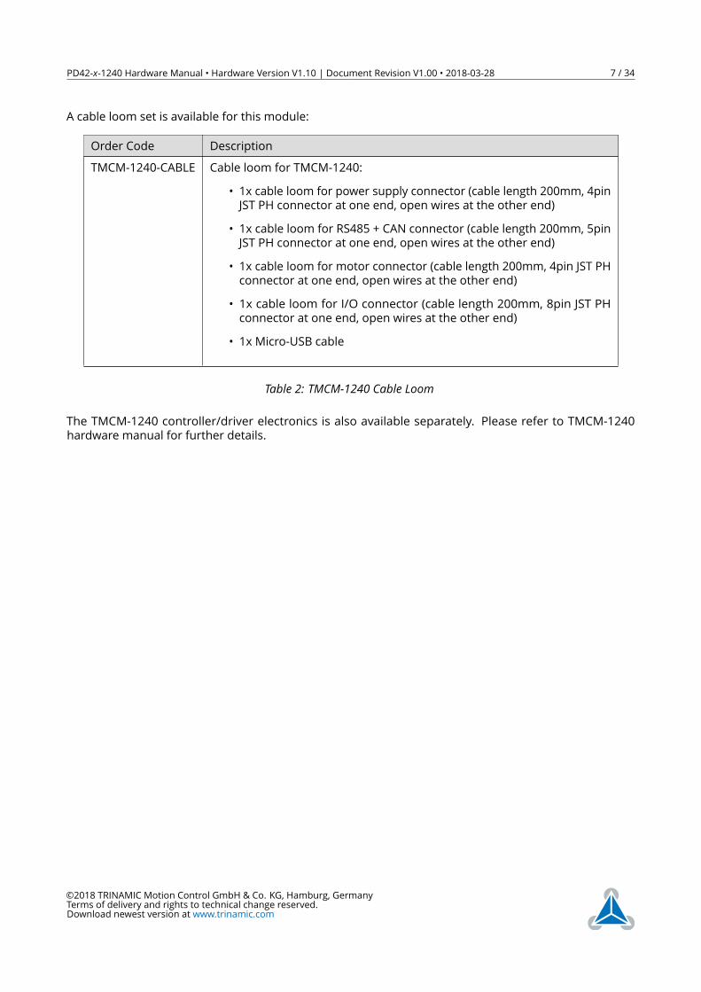
A cable loom set is available for this module:
Order Code DescriptionTMCM-1240-CABLE Cable loom for TMCM-1240:
• 1x cable loom for power supply connector (cable length 200mm, 4pinJST PH connector at one end, open wires at the other end)
• 1x cable loom for RS485 + CAN connector (cable length 200mm, 5pinJST PH connector at one end, open wires at the other end)
• 1x cable loom for motor connector (cable length 200mm, 4pin JST PHconnector at one end, open wires at the other end)
• 1x cable loom for I/O connector (cable length 200mm, 8pin JST PHconnector at one end, open wires at the other end)
• 1x Micro-USB cable
Table 2: TMCM-1240 Cable Loom
The TMCM-1240 controller/driver electronics is also available separately. Please refer to TMCM-1240hardware manual for further details.
©2018 TRINAMIC Motion Control GmbH & Co. KG, Hamburg, GermanyTerms of delivery and rights to technical change reserved.Download newest version at www.trinamic.com
PD42-x-1240 Hardware Manual • Hardware Version V1.10 | Document Revision V1.00 • 2018-03-28 8 / 34
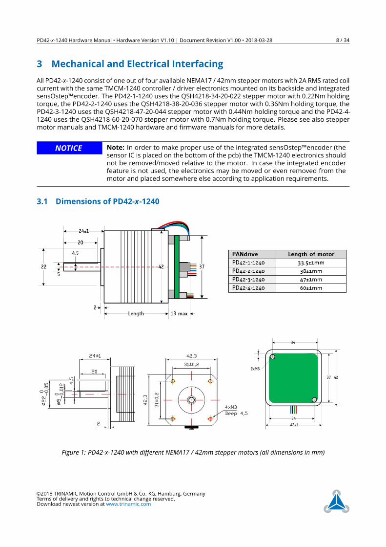
3 Mechanical and Electrical InterfacingAll PD42-x-1240 consist of one out of four available NEMA17 / 42mm stepper motors with 2A RMS rated coilcurrent with the same TMCM-1240 controller / driver electronics mounted on its backside and integratedsensOstep™encoder. The PD42-1-1240 uses the QSH4218-34-20-022 stepper motor with 0.22Nm holdingtorque, the PD42-2-1240 uses the QSH4218-38-20-036 stepper motor with 0.36Nm holding torque, thePD42-3-1240 uses the QSH4218-47-20-044 stepper motor with 0.44Nm holding torque and the PD42-4-1240 uses the QSH4218-60-20-070 stepper motor with 0.7Nm holding torque. Please see also steppermotor manuals and TMCM-1240 hardware and firmware manuals for more details.
NOTICE Note: In order to make proper use of the integrated sensOstep™encoder (thesensor IC is placed on the bottom of the pcb) the TMCM-1240 electronics shouldnot be removed/moved relative to the motor. In case the integrated encoderfeature is not used, the electronics may be moved or even removed from themotor and placed somewhere else according to application requirements.
3.1 Dimensions of PD42-x-1240
Figure 1: PD42-x-1240 with different NEMA17 / 42mm stepper motors (all dimensions in mm)
©2018 TRINAMIC Motion Control GmbH & Co. KG, Hamburg, GermanyTerms of delivery and rights to technical change reserved.Download newest version at www.trinamic.com
PD42-x-1240 Hardware Manual • Hardware Version V1.10 | Document Revision V1.00 • 2018-03-28 9 / 34
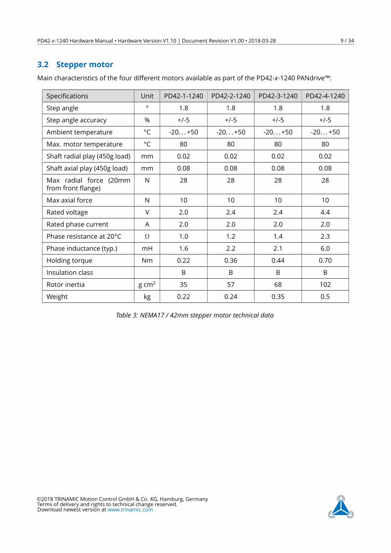
3.2 Stepper motorMain characteristics of the four different motors available as part of the PD42-x-1240 PANdrive™:
Specifications Unit PD42-1-1240 PD42-2-1240 PD42-3-1240 PD42-4-1240Step angle ° 1.8 1.8 1.8 1.8Step angle accuracy % +/-5 +/-5 +/-5 +/-5Ambient temperature °C -20. . . +50 -20. . . +50 -20. . . +50 -20. . . +50Max. motor temperature °C 80 80 80 80Shaft radial play (450g load) mm 0.02 0.02 0.02 0.02Shaft axial play (450g load) mm 0.08 0.08 0.08 0.08Max radial force (20mmfrom front flange)
N 28 28 28 28
Max axial force N 10 10 10 10Rated voltage V 2.0 2.4 2.4 4.4Rated phase current A 2.0 2.0 2.0 2.0Phase resistance at 20°C Ω 1.0 1.2 1.4 2.3Phase inductance (typ.) mH 1.6 2.2 2.1 6.0Holding torque Nm 0.22 0.36 0.44 0.70Insulation class B B B BRotor inertia g cm2 35 57 68 102Weight kg 0.22 0.24 0.35 0.5
Table 3: NEMA17 / 42mm stepper motor technical data
©2018 TRINAMIC Motion Control GmbH & Co. KG, Hamburg, GermanyTerms of delivery and rights to technical change reserved.Download newest version at www.trinamic.com
PD42-x-1240 Hardware Manual • Hardware Version V1.10 | Document Revision V1.00 • 2018-03-28 10 / 34
3.3 Integrated sensOstep™ encoderThe PD42-x-1240 PANdrives offer integrated sensOstep™ encoders based on hall sensor technology. As thename “sensOstep™“ already indicates intended use of this type of compact and highly integrated encoderis step loss detection of motor movements. As soon as the motor has been moved to a new location theposition may be verified using this encoder feedback. In case the stepper motor has lost one or multiplesteps during movement e.g. due to overload / any obstacle encountered during movement the motor axeswill jump for at least one electrical period / 4 full steps. This can be detected using the integrated encoder.In addition, step losses may be already detected during motor movements using the “deviation” settingavailable as part of the TMCL firmware (see PD42-x-1240 / TMCM-1240 firmware manual for more details).While the encoder offers 10bit (1024 steps) resolution per motor revolution the absolute position informa-tion is less accurate and depends on the displacement of the hall sensor based encoder IC relative to themagnet and motor axis among other factors. Every PANdrive™ has been tested for maximum deviationof +/- 5 encoder steps (static performance) relative to commanded microstep target position during finaltests after assembly at our factory. This will ensure more than adequate performance of the integratedsensOstep™ encoder for step loss detection during motor movements.
NOTICE Do not disassemble PANdrive™ when using integrated encoder In order tomake proper use of the integrated sensOstep™ encoder (the sensor IC is placedon the bottom center of the pcb) the TMCM-1240 electronics should not beremoved/moved relative to the motor! Otherwise encoder performance mightsuffer / not work.Note: In case the integrated encoder feature is not used, the TMCM-1240electronics may be moved or even removed from the motor and placedsomewhere else according to application requirements.
NOTICE Keep the electronics free of (metal) particles! The integrated sensOstep™encoder uses a magnet at the end of the motor axis in order to monitor positionof the motor axis. The magnet naturally attracts especially tiny metal particles.These particles might be held on the top side of the PCB and even worse startmoving in accordance with the rotating magnetic field as soon as the motor startsmoving. This might lead to shorts of electronic contacts / wires on the boardand totally erratic behavior of the module! Use compressed air for cleaning themodule if necessary (especially in prototype setups).In order to prevent shorts and better protect the electronics the TMCM-1240printed circuit board is coated after assembly of components.
©2018 TRINAMIC Motion Control GmbH & Co. KG, Hamburg, GermanyTerms of delivery and rights to technical change reserved.Download newest version at www.trinamic.com
PD42-x-1240 Hardware Manual • Hardware Version V1.10 | Document Revision V1.00 • 2018-03-28 11 / 34
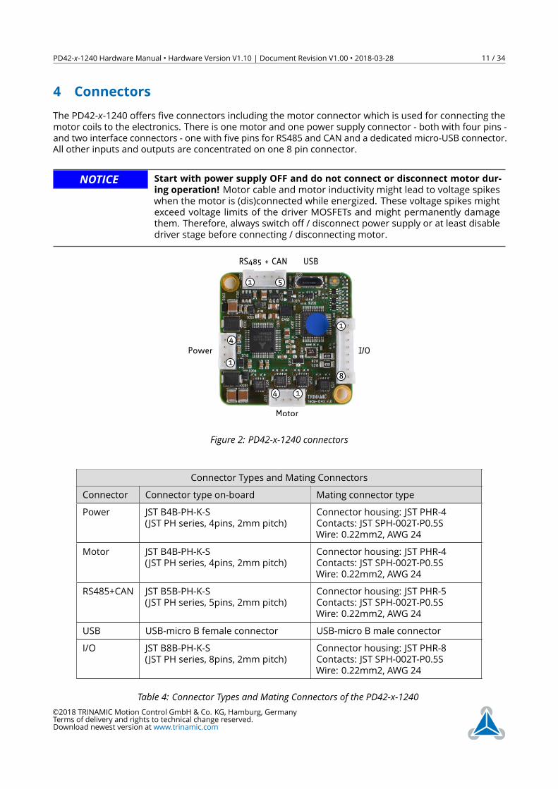
4 ConnectorsThe PD42-x-1240 offers five connectors including the motor connector which is used for connecting themotor coils to the electronics. There is one motor and one power supply connector - both with four pins -and two interface connectors - one with five pins for RS485 and CAN and a dedicated micro-USB connector.All other inputs and outputs are concentrated on one 8 pin connector.
NOTICE Start with power supply OFF and do not connect or disconnect motor dur-ing operation! Motor cable and motor inductivity might lead to voltage spikeswhen the motor is (dis)connected while energized. These voltage spikes mightexceed voltage limits of the driver MOSFETs and might permanently damagethem. Therefore, always switch off / disconnect power supply or at least disabledriver stage before connecting / disconnecting motor.
USB
Motor
Power
RS485 + CAN
1 5
1
4I/O
1
8
14
Figure 2: PD42-x-1240 connectors
Connector Types and Mating ConnectorsConnector Connector type on-board Mating connector typePower JST B4B-PH-K-S
(JST PH series, 4pins, 2mm pitch)Connector housing: JST PHR-4Contacts: JST SPH-002T-P0.5SWire: 0.22mm2, AWG 24
Motor JST B4B-PH-K-S(JST PH series, 4pins, 2mm pitch)
Connector housing: JST PHR-4Contacts: JST SPH-002T-P0.5SWire: 0.22mm2, AWG 24
RS485+CAN JST B5B-PH-K-S(JST PH series, 5pins, 2mm pitch)
Connector housing: JST PHR-5Contacts: JST SPH-002T-P0.5SWire: 0.22mm2, AWG 24
USB USB-micro B female connector USB-micro B male connectorI/O JST B8B-PH-K-S
(JST PH series, 8pins, 2mm pitch)Connector housing: JST PHR-8Contacts: JST SPH-002T-P0.5SWire: 0.22mm2, AWG 24
Table 4: Connector Types and Mating Connectors of the PD42-x-1240©2018 TRINAMIC Motion Control GmbH & Co. KG, Hamburg, GermanyTerms of delivery and rights to technical change reserved.Download newest version at www.trinamic.com
PD42-x-1240 Hardware Manual • Hardware Version V1.10 | Document Revision V1.00 • 2018-03-28 12 / 34
4.1 Power Supply Input ConnectorThe PD42-x-1240 offers one 4pin JST PH series power supply input connector. In addition to main powersupply input and related ground connection this connector offers a separate logic supply input with theoption to keep the on-board logic alive while the driver stage is switched off. It is not necesary to connectthe logic supply input in case separate supplies are not required as the main power supply input willalways supply power to the driver stage and the logic part.The power supply input connector offers a driver enable input. This input has to be connected to anyvoltage above 3.5V up-to max. supply voltage of 30V in order to enable the driver stage. Leaving this pinunconnected or connected to ground (voltage below 2.4V) will disable the driver stage regardless of anysettings in software. This input may be connected to main power supply input permanently in case anenable input in hardware is not required.
Power Supply Connector Pin AssigmentPin Label Direction Description1 GND Power (GND) Common system supply and signal ground2 VMAIN Power (input) Main power supply input for the driver and on-board logic
10. . . 30V3 Enable Digital input Driver enable input. A voltage above 3.5V is required here
in order to enable the on-board stepper motor driver. Thisinput maybe connected to main power supply input in orderto enable the driver stage (+24V tolerant input).
4 VLOGIC Power (input) Optional separate power supply input for the on-board logic10. . . 30V
Table 5: Power Supply Connector Pin Assignment
NOTICE Do not connect or disconnect motor during operation! Motor cable and mo-tor inductivity might lead to voltage spikes when the motor is (dis)connectedwhile energized. These voltage spikes might exceed voltage limits of the driverMOSFETs and might permanently damage them. Therefore, always switch off/ disconnect power supply or at least disable driver stage before connecting /disconnecting motor.
NOTICE Take care of polarity, wrong polarity can destroy the board!
NOTICE Connect Enable pin to voltage >3.5V in order to enable motor movements!
4.2 Motor ConnectorA second 4pin JST PH series connector is available for connection of a 2-phase bipolar stepper motor.
Motor Connector Pin AssignmentPin Label Direction Description1 B1 out Pin 1 of motor coil B2 B2 out Pin 2 of motor coil B
©2018 TRINAMIC Motion Control GmbH & Co. KG, Hamburg, GermanyTerms of delivery and rights to technical change reserved.Download newest version at www.trinamic.com
PD42-x-1240 Hardware Manual • Hardware Version V1.10 | Document Revision V1.00 • 2018-03-28 13 / 34
Pin Label Direction Description3 A1 out Pin 1 of motor coil A4 A2 out Pin 2 of motor coil A
Table 6: Motor Connector Pin Assignment
NOTICE Do not connect or disconnect motor during operation! Motor cable and mo-tor inductivity might lead to voltage spikes when the motor is (dis)connectedwhile energized. These voltage spikes might exceed voltage limits of the driverMOSFETs and might permanently damage them. Therefore, always switch off/ disconnect power supply or at least disable driver stage before connecting /disconnecting motor.
NOTICE Do not mix-up power supply and motor connectors!
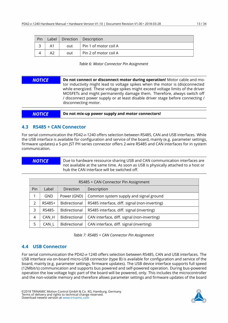
4.3 RS485 + CAN ConnectorFor serial communication the PD42-x-1240 offers selection between RS485, CAN and USB interfaces. Whilethe USB interface is available for configuration and service of the board, mainly (e.g. parameter settings,firmware updates) a 5-pin JST PH series connector offers 2-wire RS485 and CAN interfaces for in systemcommunication.
NOTICE Due to hardware ressource sharing USB and CAN communication interfaces arenot available at the same time. As soon as USB is physically attached to a host orhub the CAN interface will be switched off.
RS485 + CAN Connector Pin AssignmentPin Label Direction Description1 GND Power (GND) Common system supply and signal ground2 RS485+ Bidirectional RS485 interface, diff. signal (non-inverting)3 RS485- Bidirectional RS485 interface, diff. signal (inverting)4 CAN_H Bidirectional CAN interface, diff. signal (non-inverting)5 CAN_L Bidirectional CAN interface, diff. signal (inverting)
Table 7: RS485 + CAN Connector Pin Assignment
4.4 USB ConnectorFor serial communication the PD42-x-1240 offers selection between RS485, CAN and USB interfaces. TheUSB interface via on-board micro-USB connector (type B) is available for configuration and service of theboard, mainly (e.g. parameter settings, firmware updates). The USB device interface supports full speed(12Mbit/s) communication and supports bus powered and self-powered operation. During bus-poweredoperation the low voltage logic part of the board will be powered, only. This includes the microcontrollerand the non-volatile memory and therefore allows parameter settings and firmware updates of the board
©2018 TRINAMIC Motion Control GmbH & Co. KG, Hamburg, GermanyTerms of delivery and rights to technical change reserved.Download newest version at www.trinamic.com
PD42-x-1240 Hardware Manual • Hardware Version V1.10 | Document Revision V1.00 • 2018-03-28 14 / 34
using a standard USB cable, only. Of course, for any motor movement main supply via supply inputconnector is required.
NOTICE Due to hardware ressource sharing USB and CAN communication interfaces arenot available at the same time. As soon as USB is physically attached to a host orhub the CAN interface will be switched off.
USB Connector Pin AssignmentPin Label Direction Description1 VBUS Power (+5V) USB +5V nom. power supply input2 D- Bidirectional USB interface, diff. signal (inverting)3 D+ Bidirectional USB interface, diff. signal (inverting)4 ID Input connected to GND (via 100k resistor)5 GND Power (GND) Common system supply and signal ground
Table 8: USB Connector Pin Assignment
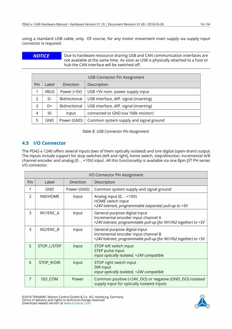
4.5 I/O ConnectorThe PD42-x-1240 offers several inputs (two of them optically isolated) and one digital (open-drain) output.The inputs include support for stop switches (left and right), home switch, step/direction, incremental A/Bchannel encoder and analog (0. . . +10V) input. All this functionality is available via one 8pin JST PH seriesI/O connector.
I/O Connector Pin AssignmentPin Label Direction Description1 GND Power (GND) Common system supply and signal ground2 IN0/HOME Input Analog input (0. . . +10V)
HOME switch input+24V tolerant, programmable (separate) pull-up to +5V
3 IN1/ENC_A Input General purpose digital inputIncremental encoder input channel A+24V tolerant, programmable pull-up (for IN1/IN2 together) to +5V
3 IN2/ENC_B Input General purpose digital inputIncremental encoder input channel B+24V tolerant, programmable pull-up (for IN1/IN2 together) to +5V
5 STOP_L/STEP Input STOP left switch inputSTEP pulse inputinput optically isolated, +24V compatible
6 STOP_R/DIR Input STOP right switch inputDIR inputinput optically isolated, +24V compatible
7 ISO_COM Power Common positive (+24V_ISO) or negative (GND_ISO) isolatedsupply input for optically isolated inputs
©2018 TRINAMIC Motion Control GmbH & Co. KG, Hamburg, GermanyTerms of delivery and rights to technical change reserved.Download newest version at www.trinamic.com
PD42-x-1240 Hardware Manual • Hardware Version V1.10 | Document Revision V1.00 • 2018-03-28 15 / 34
Pin Label Direction Description8 OUT0 Output (OD) Open-Drain output. Output will be pulled low when activated.
Voltages up-to logic supply input level (or main supply input incase separate logic supply is not used) are supported here. Max.continuous pull-down current: 100mA
Table 9: I/O Connector Pin AssignmentAll pins marked light green offer functional isolation towards main supply input. In case this is not requiredISO_COMmay be connected to main ground or supply input, of course. The opto-couppler used are ACtypes. This way, either high side switches or low side switches for both inputs are supported.
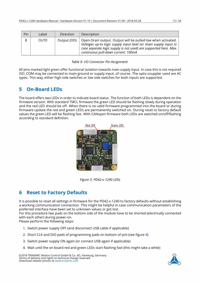
5 On-Board LEDsThe board offers two LEDs in order to indicate board status. The function of both LEDs is dependent on thefirmware version. With standard TMCL firmware the green LED should be flashing slowly during operationand the red LED should be off. When there is no valid firmware programmed into the board or duringfirmware update the red and green LEDs are permanently switched on. During reset to factory defaultvalues the green LED will be flashing fast. With CANopen firmware both LEDs are switched on/off/flashingaccording to standard defintion.
Green LEDRed LED
Figure 3: PD42-x-1240 LEDs
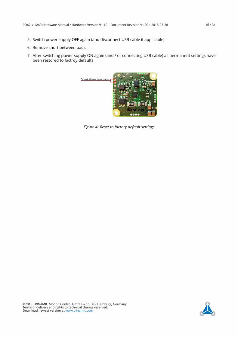
6 Reset to Factory DefaultsIt is possible to reset all settings in firmware for the PD42-x-1240 to factory defaults without establishinga working communication connection. This might be helpful in case communication parameters of thepreferred interface have been set to unknown values or got lost.For this procedure two pads on the bottom side of the module have to be shorted (electrically connectedwith each other) during power-on.Please perform the following steps:1. Switch power supply OFF (and disconnect USB cable if applicable)2. Short CLK and DIO pads of programming pads on bottom of pcb (see figure 4)3. Switch power supply ON again (or connect USB again if applicable)4. Wait until the on-board red and green LEDs start flashing fast (this might take a while)
©2018 TRINAMIC Motion Control GmbH & Co. KG, Hamburg, GermanyTerms of delivery and rights to technical change reserved.Download newest version at www.trinamic.com
PD42-x-1240 Hardware Manual • Hardware Version V1.10 | Document Revision V1.00 • 2018-03-28 16 / 34
5. Switch power supply OFF again (and disconnect USB cable if applicable)6. Remove short between pads7. After switching power supply ON again (and / or connecting USB cable) all permanent settings havebeen restored to factroy defaults
Short these two pads
Figure 4: Reset to factory default settings
©2018 TRINAMIC Motion Control GmbH & Co. KG, Hamburg, GermanyTerms of delivery and rights to technical change reserved.Download newest version at www.trinamic.com
PD42-x-1240 Hardware Manual • Hardware Version V1.10 | Document Revision V1.00 • 2018-03-28 17 / 34
7 I/OsThe I/O connector (8pin JST PH series) offers one analog input, two non-isolated digital inputs withintegrated pull-ups (programmable) and two optically isolated inputs. All inputs can be used for differentpurposes explained in more detail in the following subsections.
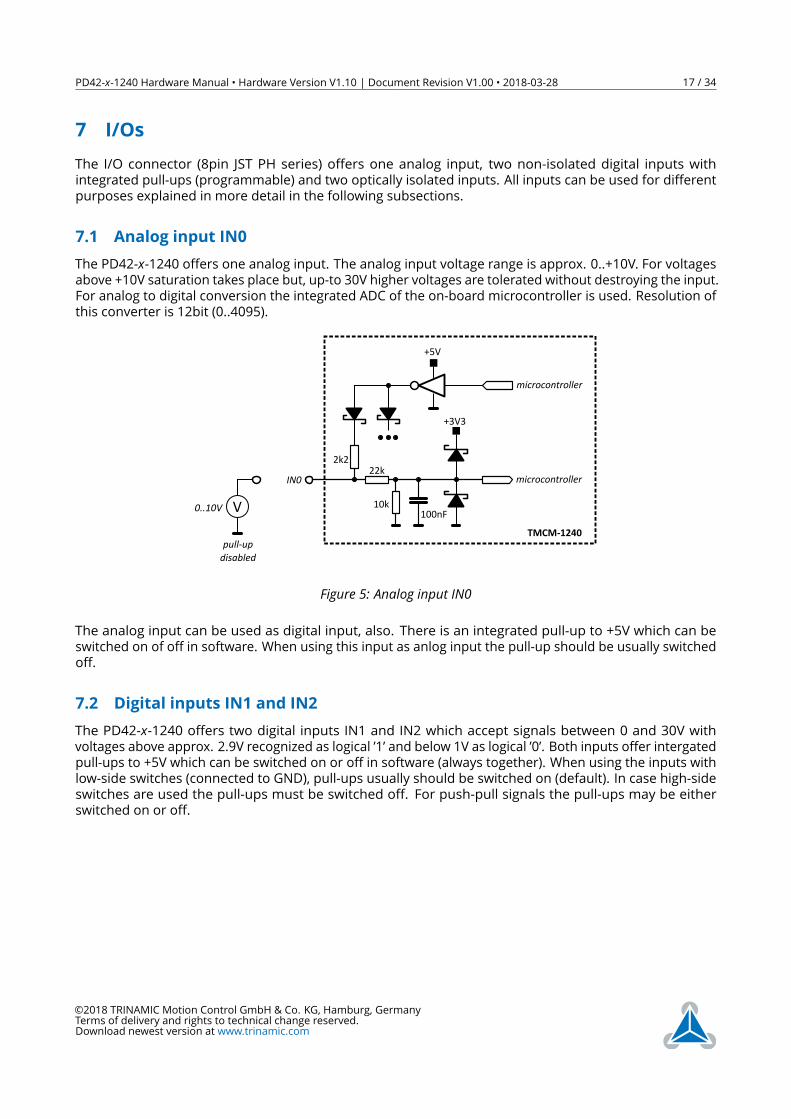
7.1 Analog input IN0The PD42-x-1240 offers one analog input. The analog input voltage range is approx. 0..+10V. For voltagesabove +10V saturation takes place but, up-to 30V higher voltages are tolerated without destroying the input.For analog to digital conversion the integrated ADC of the on-board microcontroller is used. Resolution ofthis converter is 12bit (0..4095).
100nF10k
22k2k2
+3V3
microcontroller
microcontrollerIN0
+5V
TMCM-1240pull-updisabled
V0..10V
Figure 5: Analog input IN0
The analog input can be used as digital input, also. There is an integrated pull-up to +5V which can beswitched on of off in software. When using this input as anlog input the pull-up should be usually switchedoff.
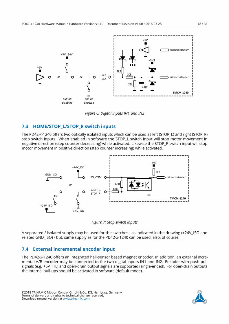
7.2 Digital inputs IN1 and IN2The PD42-x-1240 offers two digital inputs IN1 and IN2 which accept signals between 0 and 30V withvoltages above approx. 2.9V recognized as logical ’1’ and below 1V as logical ’0’. Both inputs offer intergatedpull-ups to +5V which can be switched on or off in software (always together). When using the inputs withlow-side switches (connected to GND), pull-ups usually should be switched on (default). In case high-sideswitches are used the pull-ups must be switched off. For push-pull signals the pull-ups may be eitherswitched on or off.
©2018 TRINAMIC Motion Control GmbH & Co. KG, Hamburg, GermanyTerms of delivery and rights to technical change reserved.Download newest version at www.trinamic.com
PD42-x-1240 Hardware Manual • Hardware Version V1.10 | Document Revision V1.00 • 2018-03-28 18 / 34
33pF22k
10k2k2
+3V3
microcontroller
microcontrollerIN1IN2
+5V
TMCM-1240
or
pull-upenabled
or
pull-updisabled
+5V...24V
+5V
Figure 6: Digital inputs IN1 and IN2
7.3 HOME/STOP_L/STOP_R switch inputsThe PD42-x-1240 offers two optically isolated inputs which can be used as left (STOP_L) and right (STOP_R)stop switch inputs. When enabled in software the STOP_L switch input will stop motor movement innegative direction (step counter decreasing) while activated. Likewise the STOP_R switch input will stopmotor movement in positive direction (step counter increasing) while activated.
680
6k8
2k2
+3V3
microcontroller
TMCM-1240
STOP_L,STOP_R
ISO_COM
+24V_ISO
GND_ISO
or
+24V_ISO
GND_ISO
Figure 7: Stop switch inputs
A separated / isolated supply may be used for the switches - as indicated in the drawing (+24V_ISO andrelated GND_ISO) - but, same supply as for the PD42-x-1240 can be used, also, of course.
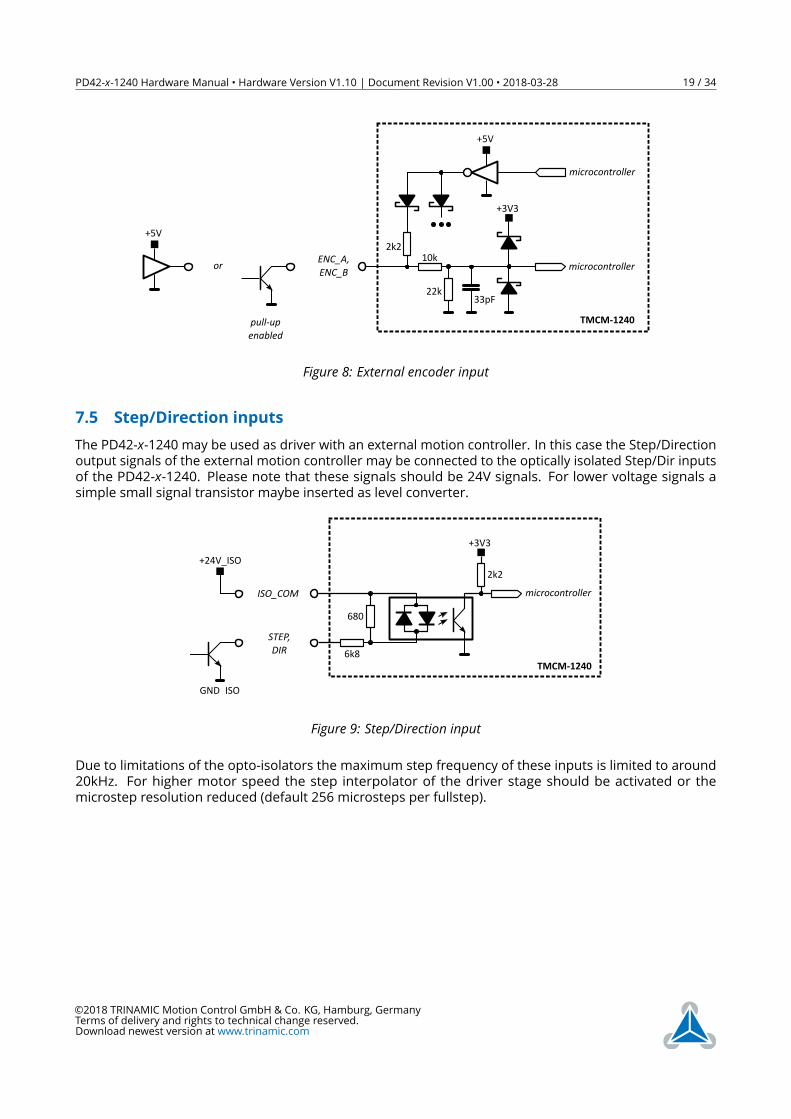
7.4 External incremental encoder inputThe PD42-x-1240 offers an integrated hall-sensor based magnet encoder. In addition, an external incre-mental A/B encoder may be connected to the two digital inputs IN1 and IN2. Encoder with push-pullsignals (e.g. +5V TTL) and open-drain output signals are supported (single-ended). For open-drain outputsthe internal pull-ups should be activated in software (default mode).
©2018 TRINAMIC Motion Control GmbH & Co. KG, Hamburg, GermanyTerms of delivery and rights to technical change reserved.Download newest version at www.trinamic.com
PD42-x-1240 Hardware Manual • Hardware Version V1.10 | Document Revision V1.00 • 2018-03-28 19 / 34
33pF22k
10k2k2
+3V3
microcontroller
microcontrollerENC_A,ENC_B
+5V
TMCM-1240
or
+5V
pull-upenabled
Figure 8: External encoder input
7.5 Step/Direction inputsThe PD42-x-1240 may be used as driver with an external motion controller. In this case the Step/Directionoutput signals of the external motion controller may be connected to the optically isolated Step/Dir inputsof the PD42-x-1240. Please note that these signals should be 24V signals. For lower voltage signals asimple small signal transistor maybe inserted as level converter.
680
6k8
2k2
+3V3
microcontroller
TMCM-1240
STEP,DIR
ISO_COM
+24V_ISO
GND_ISO
Figure 9: Step/Direction input
Due to limitations of the opto-isolators the maximum step frequency of these inputs is limited to around20kHz. For higher motor speed the step interpolator of the driver stage should be activated or themicrostep resolution reduced (default 256 microsteps per fullstep).
©2018 TRINAMIC Motion Control GmbH & Co. KG, Hamburg, GermanyTerms of delivery and rights to technical change reserved.Download newest version at www.trinamic.com
PD42-x-1240 Hardware Manual • Hardware Version V1.10 | Document Revision V1.00 • 2018-03-28 20 / 34
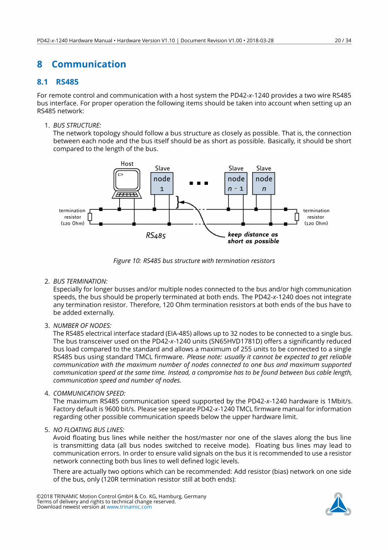
8 Communication8.1 RS485For remote control and communication with a host system the PD42-x-1240 provides a two wire RS485bus interface. For proper operation the following items should be taken into account when setting up anRS485 network:1. BUS STRUCTURE:The network topology should follow a bus structure as closely as possible. That is, the connectionbetween each node and the bus itself should be as short as possible. Basically, it should be shortcompared to the length of the bus.
c:>node1
noden - 1
noden
HostSlave Slave Slave
RS485
terminationresistor
(120 Ohm)
terminationresistor(120 Ohm)
keep distance asshort as possible
Figure 10: RS485 bus structure with termination resistors
2. BUS TERMINATION:Especially for longer busses and/or multiple nodes connected to the bus and/or high communicationspeeds, the bus should be properly terminated at both ends. The PD42-x-1240 does not integrateany termination resistor. Therefore, 120 Ohm termination resistors at both ends of the bus have tobe added externally.
3. NUMBER OF NODES:The RS485 electrical interface stadard (EIA-485) allows up to 32 nodes to be connected to a single bus.The bus transceiver used on the PD42-x-1240 units (SN65HVD1781D) offers a significantly reducedbus load compared to the standard and allows a maximum of 255 units to be connected to a singleRS485 bus using standard TMCL firmware. Please note: usually it cannot be expected to get reliablecommunication with the maximum number of nodes connected to one bus and maximum supportedcommunication speed at the same time. Instead, a compromise has to be found between bus cable length,communication speed and number of nodes.
4. COMMUNICATION SPEED:The maximum RS485 communication speed supported by the PD42-x-1240 hardware is 1Mbit/s.Factory default is 9600 bit/s. Please see separate PD42-x-1240 TMCL firmware manual for informationregarding other possible communication speeds below the upper hardware limit.
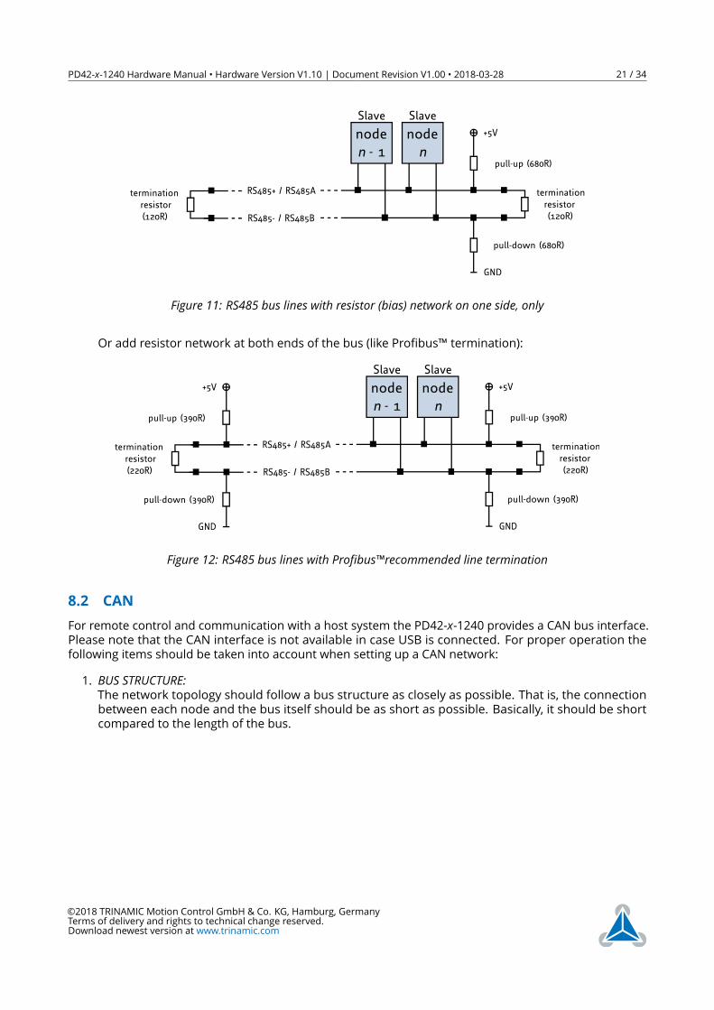
5. NO FLOATING BUS LINES:Avoid floating bus lines while neither the host/master nor one of the slaves along the bus lineis transmitting data (all bus nodes switched to receive mode). Floating bus lines may lead tocommunication errors. In order to ensure valid signals on the bus it is recommended to use a resistornetwork connecting both bus lines to well defined logic levels.There are actually two options which can be recommended: Add resistor (bias) network on one sideof the bus, only (120R termination resistor still at both ends):
©2018 TRINAMIC Motion Control GmbH & Co. KG, Hamburg, GermanyTerms of delivery and rights to technical change reserved.Download newest version at www.trinamic.com
PD42-x-1240 Hardware Manual • Hardware Version V1.10 | Document Revision V1.00 • 2018-03-28 21 / 34
noden - 1
noden
Slave Slave
terminationresistor(120R)
+5V
GND
pull-up (680R)
pull-down (680R)
RS485- / RS485B
terminationresistor(120R)
RS485+ / RS485A
Figure 11: RS485 bus lines with resistor (bias) network on one side, only
Or add resistor network at both ends of the bus (like Profibus™ termination):
noden - 1
noden
Slave Slave
terminationresistor(220R)
+5V
GND
pull-up (390R)
pull-down (390R)
RS485- / RS485B
RS485+ / RS485Aterminationresistor(220R)
+5V
GND
pull-up (390R)
pull-down (390R)
Figure 12: RS485 bus lines with Profibus™recommended line termination
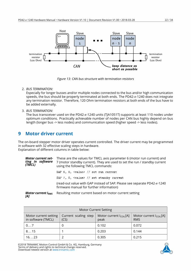
8.2 CANFor remote control and communication with a host system the PD42-x-1240 provides a CAN bus interface.Please note that the CAN interface is not available in case USB is connected. For proper operation thefollowing items should be taken into account when setting up a CAN network:1. BUS STRUCTURE:The network topology should follow a bus structure as closely as possible. That is, the connectionbetween each node and the bus itself should be as short as possible. Basically, it should be shortcompared to the length of the bus.
©2018 TRINAMIC Motion Control GmbH & Co. KG, Hamburg, GermanyTerms of delivery and rights to technical change reserved.Download newest version at www.trinamic.com
PD42-x-1240 Hardware Manual • Hardware Version V1.10 | Document Revision V1.00 • 2018-03-28 22 / 34
c:>node1
noden - 1
noden
HostSlave Slave Slave
CAN
terminationresistor
(120 Ohm)
terminationresistor(120 Ohm)
keep distance asshort as possible
Figure 13: CAN bus structure with termination resistors
2. BUS TERMINATION:Especially for longer busses and/or multiple nodes connected to the bus and/or high communicationspeeds, the bus should be properly terminated at both ends. The PD42-x-1240 does not integrateany termination resistor. Therefore, 120 Ohm termination resistors at both ends of the bus have tobe added externally.
3. BUS TERMINATION:The bus transceiver used on the PD42-x-1240 units (TJA1051T) supports at least 110 nodes underoptimum conditions. Practically achievable number of nodes per CAN bus highly depend on buslength (longer bus -> less nodes) and communication speed (higher speed -> less nodes).
9 Motor driver currentThe on-board stepper motor driver operates current controlled. The driver current may be programmedin software with 32 effective scaling steps in hardware.Explanation of different columns in table below:
Motor current set-ting in software(TMCL)
These are the values for TMCL axis parameter 6 (motor run current) and7 (motor standby current). They are used to set the run / standby currentusing the following TMCL commands:SAP 6, 0, <value> // set run current
SAP 7, 0, <value> // set standby current
(read-out value with GAP instead of SAP. Please see separate PD42-x-1240firmware manual for further information)
Motor current IRMS[A]Resulting motor current based on motor current setting
Motor Current SettingMotor current settingin software (TMCL)
Current scaling step(CS)
Motor current ICOIL[A]peak
Motor current ICOIL[A]RMS
0. . . 7 0 0.102 0.0728. . . 15 1 0.203 0.14416. . . 23 2 0.305 0.215
©2018 TRINAMIC Motion Control GmbH & Co. KG, Hamburg, GermanyTerms of delivery and rights to technical change reserved.Download newest version at www.trinamic.com
PD42-x-1240 Hardware Manual • Hardware Version V1.10 | Document Revision V1.00 • 2018-03-28 23 / 34
Motor current settingin software (TMCL)
Current scaling step(CS)
Motor current ICOIL[A]peak
Motor current ICOIL[A]RMS
24. . . 31 3 0.406 0.28732. . . 39 4 0.508 0.35940. . . 47 5 0.609 0.43148. . . 55 6 0.711 0.50356. . . 63 7 0.813 0.57564. . . 71 8 0.914 0.64672. . . 79 9 1.016 0.71880. . . 87 10 1.117 0.79088. . . 95 11 1.219 0.86296. . . 103 12 1.320 0.934104. . . 111 13 1.422 1.005112. . . 119 14 1.523 1.077120. . . 127 15 1.625 1.149128. . . 135 16 1.727 1.221136. . . 143 17 1.828 1.293144. . . 151 18 1.930 1.364152. . . 159 19 2.031 2.133160. . . 167 20 2.133 1.508168. . . 175 21 2.234 1.580176. . . 183 22 2.336 1.652184. . . 191 23 2.438 1.724192. . . 199 24 2.539 1.795200. . . 207 25 2.641 1.867208. . . 215 26 2.742 1.939216. . . 223 27 2.844 2.011224. . . 231 28 2.945 2.083232. . . 239 29 3.047 2.154240. . . 247 30 3.148 2.226248. . . 255 31 3.250 2.298
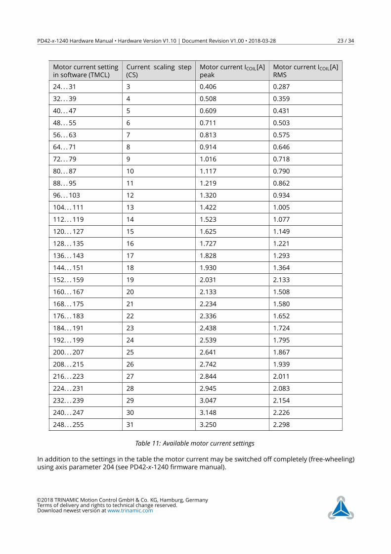
Table 11: Available motor current settingsIn addition to the settings in the table the motor current may be switched off completely (free-wheeling)using axis parameter 204 (see PD42-x-1240 firmware manual).
©2018 TRINAMIC Motion Control GmbH & Co. KG, Hamburg, GermanyTerms of delivery and rights to technical change reserved.Download newest version at www.trinamic.com
PD42-x-1240 Hardware Manual • Hardware Version V1.10 | Document Revision V1.00 • 2018-03-28 24 / 34
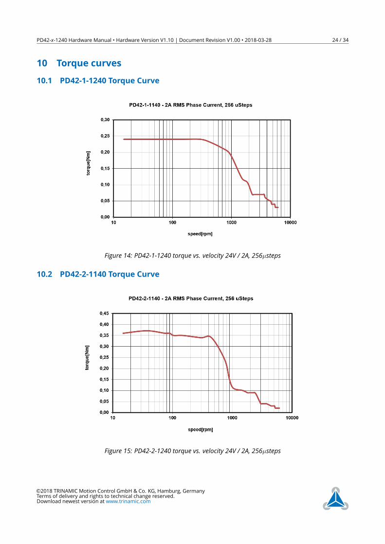
10 Torque curves10.1 PD42-1-1240 Torque Curve
Figure 14: PD42-1-1240 torque vs. velocity 24V / 2A, 256µsteps
10.2 PD42-2-1140 Torque Curve
Figure 15: PD42-2-1240 torque vs. velocity 24V / 2A, 256µsteps
©2018 TRINAMIC Motion Control GmbH & Co. KG, Hamburg, GermanyTerms of delivery and rights to technical change reserved.Download newest version at www.trinamic.com
PD42-x-1240 Hardware Manual • Hardware Version V1.10 | Document Revision V1.00 • 2018-03-28 25 / 34
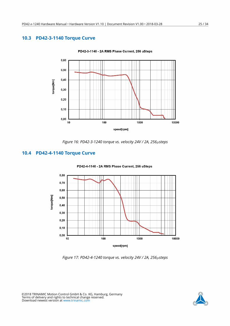
10.3 PD42-3-1140 Torque Curve
Figure 16: PD42-3-1240 torque vs. velocity 24V / 2A, 256µsteps
10.4 PD42-4-1140 Torque Curve
Figure 17: PD42-4-1240 torque vs. velocity 24V / 2A, 256µsteps
©2018 TRINAMIC Motion Control GmbH & Co. KG, Hamburg, GermanyTerms of delivery and rights to technical change reserved.Download newest version at www.trinamic.com
PD42-x-1240 Hardware Manual • Hardware Version V1.10 | Document Revision V1.00 • 2018-03-28 26 / 34
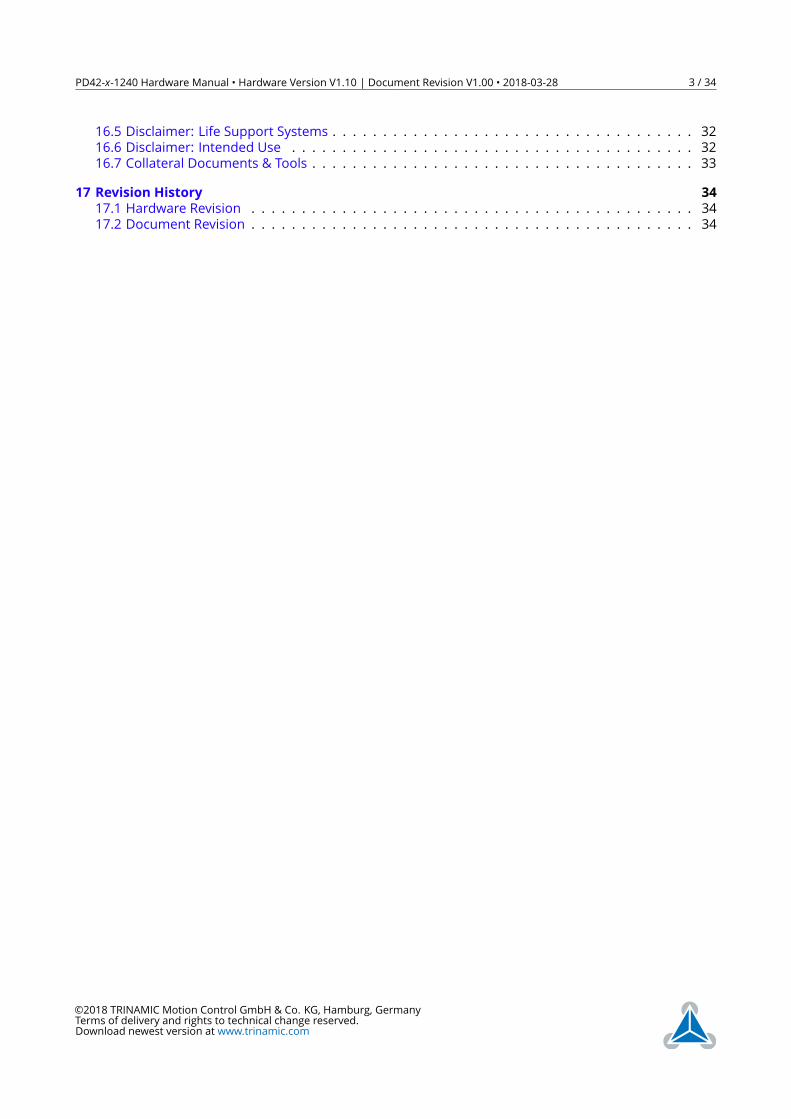
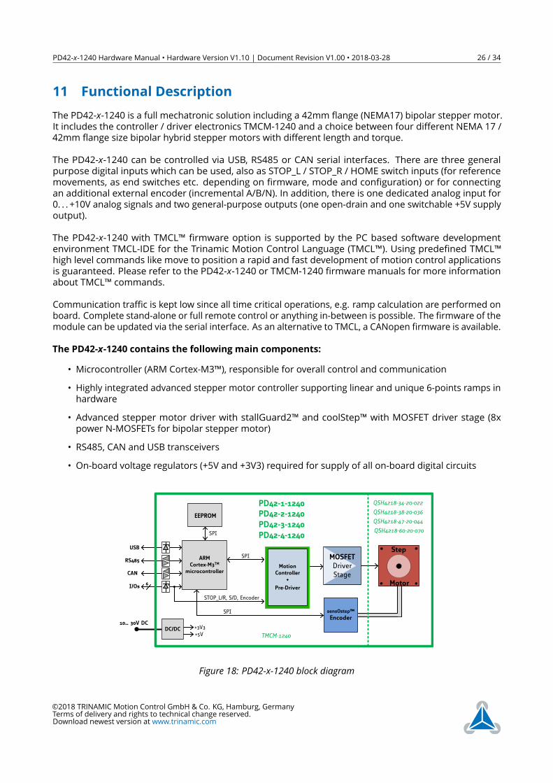
11 Functional DescriptionThe PD42-x-1240 is a full mechatronic solution including a 42mm flange (NEMA17) bipolar stepper motor.It includes the controller / driver electronics TMCM-1240 and a choice between four different NEMA 17 /42mm flange size bipolar hybrid stepper motors with different length and torque.The PD42-x-1240 can be controlled via USB, RS485 or CAN serial interfaces. There are three generalpurpose digital inputs which can be used, also as STOP_L / STOP_R / HOME switch inputs (for referencemovements, as end switches etc. depending on firmware, mode and configuration) or for connectingan additional external encoder (incremental A/B/N). In addition, there is one dedicated analog input for0. . . +10V analog signals and two general-purpose outputs (one open-drain and one switchable +5V supplyoutput).The PD42-x-1240 with TMCL™ firmware option is supported by the PC based software developmentenvironment TMCL-IDE for the Trinamic Motion Control Language (TMCL™). Using predefined TMCL™high level commands like move to position a rapid and fast development of motion control applicationsis guaranteed. Please refer to the PD42-x-1240 or TMCM-1240 firmware manuals for more informationabout TMCL™ commands.Communication traffic is kept low since all time critical operations, e.g. ramp calculation are performed onboard. Complete stand-alone or full remote control or anything in-between is possible. The firmware of themodule can be updated via the serial interface. As an alternative to TMCL, a CANopen firmware is available.The PD42-x-1240 contains the following main components:
• Microcontroller (ARM Cortex-M3™), responsible for overall control and communication• Highly integrated advanced stepper motor controller supporting linear and unique 6-points ramps inhardware
• Advanced stepper motor driver with stallGuard2™ and coolStep™ with MOSFET driver stage (8xpower N-MOSFETs for bipolar stepper motor)
• RS485, CAN and USB transceivers• On-board voltage regulators (+5V and +3V3) required for supply of all on-board digital circuits
10… 30V DC
ARMCortex-M3TM
microcontroller
EEPROM
6I/Os
RS485 MOSFETDriverStage
Energy Efficient
DriverTMC262
MotionController
+
Pre-Driver
SPI
USB
SPI
CAN
DC/DC+5V
sensOstep™
EncoderSPI
+3V3
STOP_L/R, S/D, Encoder
PD42-1-1240
Step
Motor
PD42-2-1240PD42-3-1240PD42-4-1240
QSH4218-34-20-022
QSH4218-38-20-036
QSH4218-47-20-044
QSH4218-60-20-070
TMCM-1240
Figure 18: PD42-x-1240 block diagram
©2018 TRINAMIC Motion Control GmbH & Co. KG, Hamburg, GermanyTerms of delivery and rights to technical change reserved.Download newest version at www.trinamic.com
PD42-x-1240 Hardware Manual • Hardware Version V1.10 | Document Revision V1.00 • 2018-03-28 27 / 34
12 Operational Ratings and Characteristics
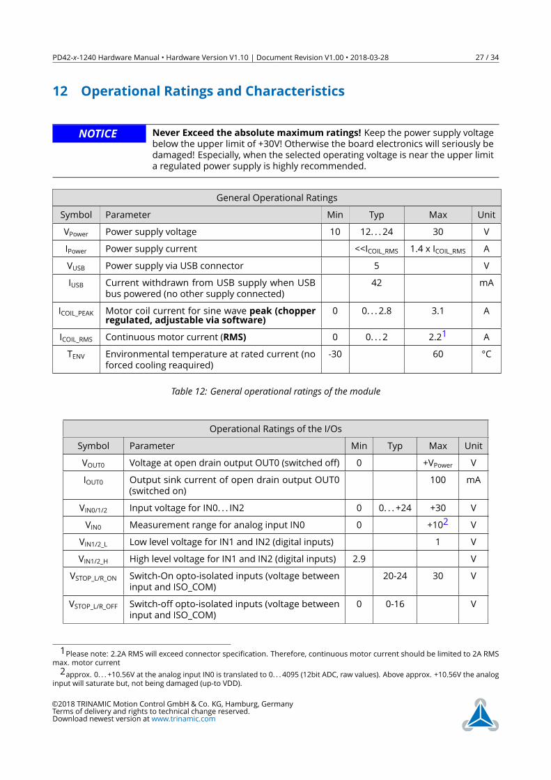
NOTICE Never Exceed the absolute maximum ratings! Keep the power supply voltagebelow the upper limit of +30V! Otherwise the board electronics will seriously bedamaged! Especially, when the selected operating voltage is near the upper limita regulated power supply is highly recommended.
General Operational RatingsSymbol Parameter Min Typ Max UnitVPower Power supply voltage 10 12. . . 24 30 VIPower Power supply current <<ICOIL_RMS 1.4 x ICOIL_RMS AVUSB Power supply via USB connector 5 VIUSB Current withdrawn from USB supply when USB
bus powered (no other supply connected)42 mA
ICOIL_PEAK Motor coil current for sine wave peak (chopperregulated, adjustable via software)
0 0. . . 2.8 3.1 A
ICOIL_RMS Continuous motor current (RMS) 0 0. . . 2 2.21 ATENV Environmental temperature at rated current (no
forced cooling reaquired)-30 60 °C
Table 12: General operational ratings of the module
Operational Ratings of the I/OsSymbol Parameter Min Typ Max UnitVOUT0 Voltage at open drain output OUT0 (switched off) 0 +VPower VIOUT0 Output sink current of open drain output OUT0
(switched on)100 mA
VIN0/1/2 Input voltage for IN0. . . IN2 0 0. . . +24 +30 VVIN0 Measurement range for analog input IN0 0 +102 VVIN1/2_L Low level voltage for IN1 and IN2 (digital inputs) 1 VVIN1/2_H High level voltage for IN1 and IN2 (digital inputs) 2.9 V
VSTOP_L/R_ON Switch-On opto-isolated inputs (voltage betweeninput and ISO_COM)
20-24 30 V
VSTOP_L/R_OFF Switch-off opto-isolated inputs (voltage betweeninput and ISO_COM)
0 0-16 V
1Please note: 2.2A RMS will exceed connector specification. Therefore, continuous motor current should be limited to 2A RMSmax. motor current2approx. 0. . . +10.56V at the analog input IN0 is translated to 0. . . 4095 (12bit ADC, raw values). Above approx. +10.56V the analog
input will saturate but, not being damaged (up-to VDD).
©2018 TRINAMIC Motion Control GmbH & Co. KG, Hamburg, GermanyTerms of delivery and rights to technical change reserved.Download newest version at www.trinamic.com
PD42-x-1240 Hardware Manual • Hardware Version V1.10 | Document Revision V1.00 • 2018-03-28 28 / 34
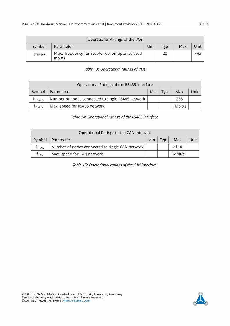
Operational Ratings of the I/OsSymbol Parameter Min Typ Max UnitfSTEP/DIR Max. frequency for step/direction opto-isolated
inputs20 kHz
Table 13: Operational ratings of I/Os
Operational Ratings of the RS485 InterfaceSymbol Parameter Min Typ Max UnitNRS485 Number of nodes connected to single RS485 network 256fRS485 Max. speed for RS485 network 1Mbit/s
Table 14: Operational ratings of the RS485 interface
Operational Ratings of the CAN InterfaceSymbol Parameter Min Typ Max UnitNCAN Number of nodes connected to single CAN network >110fCAN Max. speed for CAN network 1Mbit/s
Table 15: Operational ratings of the CAN interface
©2018 TRINAMIC Motion Control GmbH & Co. KG, Hamburg, GermanyTerms of delivery and rights to technical change reserved.Download newest version at www.trinamic.com
PD42-x-1240 Hardware Manual • Hardware Version V1.10 | Document Revision V1.00 • 2018-03-28 29 / 34
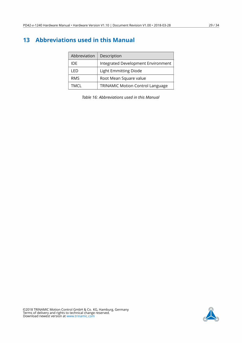
13 Abbreviations used in this Manual
Abbreviation DescriptionIDE Integrated Development EnvironmentLED Light Emmitting DiodeRMS Root Mean Square valueTMCL TRINAMIC Motion Control Language
Table 16: Abbreviations used in this Manual
©2018 TRINAMIC Motion Control GmbH & Co. KG, Hamburg, GermanyTerms of delivery and rights to technical change reserved.Download newest version at www.trinamic.com
PD42-x-1240 Hardware Manual • Hardware Version V1.10 | Document Revision V1.00 • 2018-03-28 30 / 34
14 Figures Index1 PD42-x-1240 with different NEMA17 /
42mm stepper motors (all dimensionsin mm) . . . . . . . . . . . . . . . . . . 8
2 PD42-x-1240 connectors . . . . . . . . 113 PD42-x-1240 LEDs . . . . . . . . . . . . 154 Reset to factory default settings . . . 165 Analog input IN0 . . . . . . . . . . . . 176 Digital inputs IN1 and IN2 . . . . . . . 187 Stop switch inputs . . . . . . . . . . . 188 External encoder input . . . . . . . . . 199 Step/Direction input . . . . . . . . . . 1910 RS485 bus structure with termination
resistors . . . . . . . . . . . . . . . . . 2011 RS485 bus lines with resistor (bias) net-
work on one side, only . . . . . . . . . 21
12 RS485 bus lines with Profibus™recommendedline termination . . . . . . . . . . . . . 21
13 CAN bus structure with terminationresistors . . . . . . . . . . . . . . . . . 22
14 PD42-1-1240 torque vs. velocity 24V /2A, 256µsteps . . . . . . . . . . . . . . 24
15 PD42-2-1240 torque vs. velocity 24V /2A, 256µsteps . . . . . . . . . . . . . . 24
16 PD42-3-1240 torque vs. velocity 24V /2A, 256µsteps . . . . . . . . . . . . . . 25
17 PD42-4-1240 torque vs. velocity 24V /2A, 256µsteps . . . . . . . . . . . . . . 25
18 PD42-x-1240 block diagram . . . . . . 26
©2018 TRINAMIC Motion Control GmbH & Co. KG, Hamburg, GermanyTerms of delivery and rights to technical change reserved.Download newest version at www.trinamic.com
PD42-x-1240 Hardware Manual • Hardware Version V1.10 | Document Revision V1.00 • 2018-03-28 31 / 34
15 Tables Index1 Order Code . . . . . . . . . . . . . . . 62 TMCM-1240 Cable Loom . . . . . . . . 73 NEMA17 / 42mm stepper motor tech-
nical data . . . . . . . . . . . . . . . . . 94 Connector Types and Mating Connec-
tors of the PD42-x-1240 . . . . . . . . 115 Power Supply Connector Pin Assignment 126 Motor Connector Pin Assignment . . 137 RS485 + CAN Connector Pin Assignment 138 USB Connector Pin Assignment . . . . 149 I/O Connector Pin Assignment . . . . 15
11 Available motor current settings . . . 2312 General operational ratings of the
module . . . . . . . . . . . . . . . . . . 2713 Operational ratings of I/Os . . . . . . 2814 Operational ratings of the RS485 inter-
face . . . . . . . . . . . . . . . . . . . . 2815 Operational ratings of the CAN interface 2816 Abbreviations used in this Manual . . 2917 Hardware Revision . . . . . . . . . . . 3418 Document Revision . . . . . . . . . . . 34
©2018 TRINAMIC Motion Control GmbH & Co. KG, Hamburg, GermanyTerms of delivery and rights to technical change reserved.Download newest version at www.trinamic.com
PD42-x-1240 Hardware Manual • Hardware Version V1.10 | Document Revision V1.00 • 2018-03-28 32 / 34
16 Supplemental Directives16.1 Producer Information16.2 CopyrightTRINAMIC owns the content of this user manual in its entirety, including but not limited to pictures, logos,trademarks, and resources. © Copyright 2018 TRINAMIC. All rights reserved. Electronically published byTRINAMIC, Germany.Redistributions of source or derived format (for example, Portable Document Format or Hypertext MarkupLanguage) must retain the above copyright notice, and the complete Datasheet User Manual docu-mentation of this product including associated Application Notes; and a reference to other availableproduct-related documentation.
16.3 Trademark Designations and SymbolsTrademark designations and symbols used in this documentation indicate that a product or feature isowned and registered as trademark and/or patent either by TRINAMIC or by other manufacturers, whoseproducts are used or referred to in combination with TRINAMIC’s products and TRINAMIC’s product docu-mentation.This HardwareManual is a non-commercial publication that seeks to provide concise scientific and technicaluser information to the target user. Thus, trademark designations and symbols are only entered in theShort Spec of this document that introduces the product at a quick glance. The trademark designation/symbol is also entered when the product or feature name occurs for the first time in the document. Alltrademarks and brand names used are property of their respective owners.
16.4 Target UserThe documentation provided here, is for programmers and engineers only, who are equipped with thenecessary skills and have been trained to work with this type of product.The Target User knows how to responsibly make use of this product without causing harm to himself orothers, and without causing damage to systems or devices, in which the user incorporates the product.
16.5 Disclaimer: Life Support SystemsTRINAMIC Motion Control GmbH & Co. KG does not authorize or warrant any of its products for use in lifesupport systems, without the specific written consent of TRINAMIC Motion Control GmbH & Co. KG.Life support systems are equipment intended to support or sustain life, and whose failure to perform,when properly used in accordance with instructions provided, can be reasonably expected to result inpersonal injury or death.Information given in this document is believed to be accurate and reliable. However, no responsibilityis assumed for the consequences of its use nor for any infringement of patents or other rights of thirdparties which may result from its use. Specifications are subject to change without notice.
16.6 Disclaimer: Intended UseThe data specified in this user manual is intended solely for the purpose of product description. No repre-sentations or warranties, either express or implied, of merchantability, fitness for a particular purpose
©2018 TRINAMIC Motion Control GmbH & Co. KG, Hamburg, GermanyTerms of delivery and rights to technical change reserved.Download newest version at www.trinamic.com
PD42-x-1240 Hardware Manual • Hardware Version V1.10 | Document Revision V1.00 • 2018-03-28 33 / 34
or of any other nature are made hereunder with respect to information/specification or the products towhich information refers and no guarantee with respect to compliance to the intended use is given.In particular, this also applies to the stated possible applications or areas of applications of the product.TRINAMIC products are not designed for and must not be used in connection with any applications wherethe failure of such products would reasonably be expected to result in significant personal injury or death(safety-Critical Applications) without TRINAMIC’s specific written consent.TRINAMIC products are not designed nor intended for use in military or aerospace applications or environ-ments or in automotive applications unless specifically designated for such use by TRINAMIC. TRINAMICconveys no patent, copyright, mask work right or other trademark right to this product. TRINAMIC assumesno liability for any patent and/or other trade mark rights of a third party resulting from processing orhandling of the product and/or any other use of the product.
16.7 Collateral Documents & ToolsThis product documentation is related and/or associated with additional tool kits, firmware and otheritems, as provided on the product page at: www.trinamic.com.
©2018 TRINAMIC Motion Control GmbH & Co. KG, Hamburg, GermanyTerms of delivery and rights to technical change reserved.Download newest version at www.trinamic.com
PD42-x-1240 Hardware Manual • Hardware Version V1.10 | Document Revision V1.00 • 2018-03-28 34 / 34
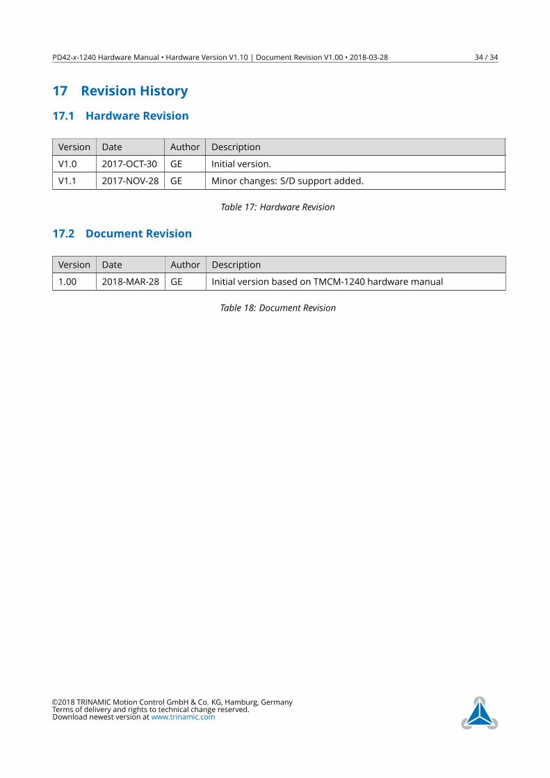
17 Revision History17.1 Hardware Revision
Version Date Author DescriptionV1.0 2017-OCT-30 GE Initial version.V1.1 2017-NOV-28 GE Minor changes: S/D support added.
Table 17: Hardware Revision
17.2 Document Revision
Version Date Author Description1.00 2018-MAR-28 GE Initial version based on TMCM-1240 hardware manual
Table 18: Document Revision
©2018 TRINAMIC Motion Control GmbH & Co. KG, Hamburg, GermanyTerms of delivery and rights to technical change reserved.Download newest version at www.trinamic.com


![PD42-x-1140 Hardware Manual...the most energy-efficient point of operation for the motor. Load [Nm] stallGuard2 Initial stallGuard2 (SG) value: 100% Max. load stallGuard2 (SG) value:](https://img.pdfslide.net/doc/110x75/5f61d503e7e48e24d34a45e9/pd42-x-1140-hardware-manual-the-most-energy-efficient-point-of-operation-for.jpg)