Embed Size (px)
Citation preview

Journal of Physics Conference Series
OPEN ACCESS
Cryogenic technology for CMBPolTo cite this article M DiPirro et al 2009 J Phys Conf Ser 155 012008
View the article online for updates and enhancements
You may also likeThe Use of Ester Co-Solvent Based LowTemperature Electrolytes in Experimentaland Large Capacity Prototype Graphite-LiNiCoAlO2 Lithium-Ion CellsMarshall C Smart Ratnakumar V BuggaJohn-Paul Jones et al
-
The Use of Low Temperature Electrolytesin High Specific Energy Li-Ion Cells forFuture NASA Missions to Icy MoonsMarshall C Smart Frederick C KrauseJohn-Paul Jones et al
-
Electrochemical Characterization of theLithium-Ion Cells Assembled with Ester-Based Electrolyte at Low TemperatureSeung Hark Park Sang-Hyung KimSoojin Kim et al
-
Recent citationsCooling capability of JT coolers during thecool-down phase for space sciencemissionsKeisuke Shinozaki et al
-
Reprint of ldquoCoordination compounds andthe magnetocaloric effectrdquoJoseph W Sharples and David Collison
-
Coordination compounds and themagnetocaloric effectJoseph W Sharples and David Collison
-
This content was downloaded from IP address 416023795 on 16122021 at 1446
Cryogenic Technology for CMB-Pol
M DiPirro(a) D L Johnson(b) P Shirron(a)
(a)NASAGoddard Space Flight Center Greenbelt MD 20771 (b)Jet Propulsion Laboratory California Institute of Technology Pasadena CA 91109 E-mail mikedipirronasagov Abstract Future space telescopes such as CMBPol SAFIR DARWIN SPICA and XEUS will require cooling to very low temperatures Staged cooling is the most efficient means of achieving low temperature in an observatory or instrument with the least cost and mass The first stage is usually passive radiators taking advantage of views to deep space In the past stored cryogen systems provided the next lower stagesof cooling Mechanical cryocoolers represent a significant enabling technology especially at the lower temperatures where the passive coolersrsquo effectiveness is limited These coolers are in general lighter have more cooling capability and more operationally flexible than stored cryogens Sub Kelvin cooling is required for many of the most sensitive detectors For fundamental reasons microcalorimeters and bolometers must be cooled to extremely low temperature to achieve their ultimate resolution and eventually background-limited detection The state of the art for these cryogenic cooling technologies are presented along with plans to advance the technology readiness level to enable these future missions
1 Passive Cooling When designing a low temperature system for an instrument or an observatory it is most efficient to use multiple stage of cooling ndash both for thermodynamic efficiency and to utilize optimal cooling techniques for the various temperature ranges The first (warmest) stage of cooling is usually passive Passive cooling systems block parasitic heat inputs from the Sun Earth spacecraft and other warm components from reaching the low temperature stages Passive cooling systems also take advantage of the biggest heat sink in the universe to radiate heat to deep space V-Groove radiators provide one or more stages of radiation in an optimal direction defined by the ldquoVrdquo while blocking radiated heat from the other directions[1] Planck is a good example of a multi-stage fixed V-groove radiator[2] A larger very light weight deployable version of a V groove radiator can be found in the James Webb Space Telescope (JWST) sunshield[3] (See Figure 2) The shield is made up of 5 layers of aluminized or Si coated Kapton to provide more than 40 dB of attenuation of the incident sunlight power while radiating to space out the gaps between layers The size and mass limitations limit the membrane shape and layer separation that can be achieved on the ground This in turn limits the testability of the design
Technology Development for a CMB Probe of Inflation IOP PublishingJournal of Physics Conference Series 155 (2009) 012008 doi1010881742-65961551012008
ccopy 2009 IOP Publishing Ltd 1
Because of the proximity angular coverage and varying direction of thermal radiation and reflected sunlight from the Earth low Earth orbit (LEO) is thermally inferior to a deep space orbit like the Earth-Sun L2 Lagrange point or a drift-away orbit L2 was used by the Wilkinson Microwave Anisotropy Probe (WMAP) which radiatively achieved 90 K[4] and will be used by Herschel[5] and Planck followed by JWST (27 K on the instrument radiators) With a very simple fixed shield and radiator Spitzer has achieved 34 K in a drift-away solar orbit[6] while the outer shell of the COBE dewar in LEO reached 138 K
Note that while the cosmic microwave background temperature is 273 K deep space is effectively 7 K due to inner solar system dust[7] This difference is not a practical limitation however due to the T4 dependence of radiation and the other practical limitation on radiators such as conductive supports The difference between the two space temperatures on the radiation from the Spitzer outer shell at 34 K is only 02
The Spitzer observatory consists of a 085 m diameter telescope cooled to 55 K by the boil-off gas from a superfluid helium dewar The telescope is mounted directly to the dewar and supported from a radiative cooled outer shell with a vapor cooled shield in between See Figure 1 The helium dewar is described in the next section The outer shell which is cooled entirely by radiation is silvered on the side facing the solar array and the sun and is painted with Ball InfraRed Black (BIRB) on the deep space facing side The radiative performance turned out to be as predicted based on heat load from the solar array the conduction of the outer shell and the emissivity of the BIRB[6]
The thermal testing of passive cooling systems is problematic not only due to the size and gravity effects but also due to the difficulty of achieving and measuring milliwatt heat loads in the presence of kilowatts of thermal radiation from room temperature spacecraft components within the same thermalvacuum chamber A very big thermal driver is the difference between real chamber walls and empty space The warm spacecraft and any solar simulator can be seen by the cold portions of the instrument through reflections off these walls The chamber also needs to be cold enough so that radiation from the wall itself is not significant Even a great observatory like Spitzer could not afford a test that would adequately simulate the thermal environment of space The ldquoinexpensiverdquo compromise test that was run on Spitzer resulted in a heat load to the instrument that was 10 times the actual on-orbit value so was of little use in predicting on orbit behavior
To overcome this limitation it is proposed that the problem be attacked in two ways make and test a subscale hardware model of the thermal system of a realistic large space telescope and perform a thermal model on this subscale model and test conditions and outfit the test chamber with the appropriate thermal baffling and cold black body surfaces to achieve a more space-like thermal
Figure 1 The Spitzer Space Telescope outer shell cools radiatively to 34 K
Figure 2 The James Webb Space Telescope will cool its telescope radiatively to 40 K and
its instruments to 27 K
Technology Development for a CMB Probe of Inflation IOP PublishingJournal of Physics Conference Series 155 (2009) 012008 doi1010881742-65961551012008
2
environment The first enables use of a smaller chamber which lowers the cost and increases the opportunities for test It also helps with the one-g problem ndash in general the smaller the system the less effect gravity has on it The second requires a careful design of a chamberexperiment baffle This is also aided by making the test article smaller One can vary the boundary conditions on the resulting test article to simulate conditions like LEO or deep space JWST will test its sunshield design on a one third scale model The size was chosen to make use of existing thermal vacuum chambers and to provide the proper scaling That is too small a model will be dominated by conduction and boundary effects while too large a model will be affected by gravity and facility availability
To demonstrate the feasibility of this scheme an 18 scale (the largest diameter shield was 15 m) version of the SPIRIT Origins Probe telescope shield was tested in a low cost helium shroud within a LN2 shrouded vacuum chamber See Figure 3 Performance data showed that less than 10 microwatts of radiative heat leaked from the warm to cold sides of the shields during the test implying that the boundary conditions were well understood Excellent agreement was obtained between the data and the thermal models[8]
2 Stored Cryogen Cooling Several cryogens solid and liquid have been used as consumables to cool instruments and
observatories Volumes have ranged from 36 liters (Astro-H) to over 2500 liters (Herschel) See Figure 4 Most were great successes but there have been some notable failures IRAS COBE CLAES IRTS ISO[9] GP-B[10] and Spitzer[6] are in the latter category The Hubble Near Infrared Camera and MultiObject Spectrograph (NICMOS) which used solid nitrogen had a much shorter on-orbit lifetime due to a thermal short caused by the solid nitrogen itself The Wide field InfraRed Explorer (WIRE) which was cooled by two stages of solid hydrogen had a premature release of its aperture cover which enabled sunlight to enter the cold volume and exhausted the hydrogen within one day The Suzaku XRS2 instrument cooled by a combination of mechanical cooler at 100 K solid neon at 16 K and superfluid helium suffered a complete loss of helium four weeks into the mission when vented gas reentered the dewar vacuum space It is noted that all of these failures were peculiar to using stored cryogens and would not have happened to a mechanical cryocooler system In fact NICMOS was brought back into service by attaching a cryocooler to the dewar in 2002 and is still successfully operating[11]
The successor to the Japanese Suzaku xray mission is Astro-H The current thinking on the cryogenic system is to use both a superfluid helium tank and a Joule-Thomson cryocooler to achieve technological redundancy While this does provide redundancy it has a distinct mass disadvantage to either of the two cooling systems alone
Figure 3 Demonstration of subscale thermal testing of a large sunshield system
Technology Development for a CMB Probe of Inflation IOP PublishingJournal of Physics Conference Series 155 (2009) 012008 doi1010881742-65961551012008
3
The Spitzer cryogenic system approaches the optimum engineered solution for stored helium systems The combination of excellent passive cooling and careful thermal design produced a cryogenic system whose lifetime is expected to exceed its 5 year goal using only 360 liters of superfluid helium The Spitzer mirror is cooled to 55 K by the boil off vapor from a superfluid helium tank that operates at 12 K A heat load to the superfluid helium of 6 mW coincidently produces about 6 mW of cooling by the vapor at 55 K the enthalpy difference of the gas from 12 K to 55 K being approximately equal to the latent heat at 12 K The average instrument dissipation is about 3 mW which is directly deposited into the liquid The outside shell of the dewar is itself cooled by the boil-off resulting in a negligible parasitic heat load to the superfluid The remainder of the 6 mW is generated by a heater (25 mW average) and by excess superfluid film flow (05 mW)
The liquid is phase separated from the gas by a porous plug in the vent line For low flow rates the superfluid film flow leaking past the porous plug is a substantial fraction of the total flow of gas vented In Spitzer this was controlled by instituting a 35 mm diameter tube immediately downstream of the porous plug which limited the film flow to a calculated 05 mW equivalent More drastic measures were used to eliminate the film from the XRS instrument on Astro-E and Suzaku[12]
From the Spitzer example one can see that cooling by vapor alone would not be efficient for a CMB-Pol telescope operating at 27 K Some of the cooling would be generated by a weak thermal link directly from the telescopeinstrument into the superfluid helium tank
Figure 4 The large and the small On the left is the Herschel observatory with its 2560 liter helium tank in black in the center On the right is the Suzaku observatory with the 32 liter shiny helium tank near the bottom The pictures are roughly to scale Herschel is expected to last over 5 years while Suzaku was designed for a 2-3 year cryogen lifetime By using very low temperature cryocoolers the successor to Suzaku Astro-H is expected to have a lifetime in excess of 5 years using only 36 liters of helium
Technology Development for a CMB Probe of Inflation IOP PublishingJournal of Physics Conference Series 155 (2009) 012008 doi1010881742-65961551012008
4
At these low flow rates the vapor cooling is also small The inner vapor cooled shield just outside the telescope settles at 24 K This implies a vapor cooling of only 275 mW at this shield
It is useful to estimate the realistic heat loads for a system like CMB-Pol Assume a 3 m diameter primary mirror operating at 27 K One can get a handle on the expected heat loads by scaling from Spitzer The Spitzer primary is 085 meter in diameter The cooled mass includes the entire helium dewar including the vacuum shell and is 240 kg Of this about 140 kg is the dewar and helium itself Roughly one third of the cold surface area is due to the dewar The parasitic heat loads come from conduction in structural supports and electrical leads and radiation from the surrounding 24 K shield which is cooled by the boil-off vapor The mirror and instrument mass is roughly 100 kg The total heat load at 55 K for Spitzer is 6 mW The structural support may be scaled linearly with mass and with the square of the shield temperature that is used to intercept conducted heat The radiation may be scaled linearly with surface area and as the 4th power of the shield temperature and the electrical leads which feed the instruments and telescope mechanisms will be roughly the same The mass of the instrument will be assumed to be constant at 75 kg and the mirror and structure will scale as the cube of the dimension The outside surface area will scale with the square of the linear dimension If one arbitrarily assigns 2 mW each to the structure conduction lead conduction and the radiation for Spitzer then the values expected for CMB-Pol are 17 mW conduction and 25 mW from radiation for a total of 44 mW For a 5 year mission this would lead to a 2700 liter dewar - on the order of the size of the ISO Herschel and GP-B dewars Such a large dewar would probably force the observatory into the heavy lift category of rockets
Note that it is not necessary for the stored cryogen system (or mechanical cooler for that matter) to reach the telescopeinstrument operating temperature of 27 K A closed cycle JT expander and sorption cooler or an Adiabatic Demagnetization Refrigerator (ADR) could provide the final stage of cooling from 10 K or so In that case a SH2 dewar could be used with its higher latent heat and consequently lower mass
3 General Comments Large uncertainties exist in the thermal designs for space flight cryogenic systems To accommodate these uncertainties the AIAA Spacecraft Thermal Control Handbook recommends design margins for cryogenic systems of 50 at project start falling to 35 at the critical design review and 25 at launch[13] Here margin is defined as the predicted heat load subtracted from the cooling capability divided by the cooling capability These margins have been derived from flight project experience It is noted that the last preflight predictions for lifetimes of both IRAS and COBE were 25 above the actual lifetime achieved on orbit
Mechanical cryocoolers provide the competition for stored cryogen systems over the range from room temperature to a few K The trade-off between the two usually comes down to cost mass (which can equate to launch cost) technology readiness level (TRL) reliability and redundancy servicing and operational flexibility A stored cryogen is a large potential cooling capacity it is equivalent to energy To compare with continuously produced cooling from a passive radiator or mechanical cooler for instance it is necessary to know the requirement and goal for mission lifetime In general for missions expected to last more than one year a mechanical cryocooler will be the more cost effective solution
The total mass of a cryocooler system must include the power system (solar arrays power conditioning electronics batteries and cryocooler controllers the radiators to dissipate the cryocooler power as well as the cryocooler components itself Even so the overall mass trade came down in favor of a cryocooler system for JWST (240 kg vs 50 kg) In addition the dewar mass and volume must all be absorbed in the cold section of the instrument or observatory Mass here is at a premium due to the need to limit parasitic heat loads through the structure
An assessment of the maturity of a technology is usually made through the use of its Technology Readiness Level (TRL) The TRL of a component or subsystem is defined on a numerical score of 1-9 with 1 being the least mature (the device exists as a concept only) through TRL 9 (the device has
Technology Development for a CMB Probe of Inflation IOP PublishingJournal of Physics Conference Series 155 (2009) 012008 doi1010881742-65961551012008
5
flown in its present form) See Table 1 It is generally assumed that stored cryogen systems have a TRL of 7-9 because many dewars have flown before In fact helium dewar systems are generally TRL 5 at best because the design is always somewhat different As a case in point the COBE dewar was supposed to be a rebuild of the successful IRAS dewar but in fact 50 of the drawings were changed including the cryogen tank size
A stored cryogen system in general is not redundant It is extremely cumbersome for a dewar system to include redundancy without providing a completely separate cryostat Even components
Table 1 Definitions of Technology Readiness Levels (TRLs) TRL Definition Hardware Description Exit Criteria
1 Basic principles observed and reported
Scientific knowledge generated underpinning hardware technology conceptsapplications
Peer reviewed publication of research underlying the proposed conceptapplication
2 Application andor operating concept formulated
Invention begins practical application is identified but is speculative no experimental proof or detailed analysis is available to support the conjecture
Documented description of the applicationconcept that addresses feasibility and benefit
3 Analytical andor experimental proof-of-concept demonstrated
Analytical studies place the technology in an appropriate context and laboratory demonstrations modeling and simulation validate analytical prediction
Documented analyticalexperimental results validating predictions of key parameters
4 Low-fidelity functionality demonstrated in laboratory
A systemcomponent breadboard is built and operated to demonstrate basic functionality and critical test environments and associated performance predictions are defined relative to the final operating environment
Documented test performance demonstrating agreement with analytical predictions Documented definition of relevant environment
5 Mid-fidelity functionality demonstrated in a relevant environment
A systemcomponent brassboard is built and operated to demonstrate overall performance in a simulated operational environment with realistic support elements that demonstrates overall performance in critical areas
Documented test performance demonstrating agreement with analytical predictions Documented definition of scaling requirements
6 Mid-fidelity functionality and scaled formfit demonstrated in a relevant environment
A systemcomponent prototype that adequately addresses all critical scaling issues is built and operated in a relevant environment to demonstrate under critical environmental conditions
Documented test performance demonstrating agreement with analytical predictions
7 High-fidelity functionality and scaled formfit demonstrated in its operational environment
An engineering unit that adequately addresses all critical scaling issues is built and operated in a relevant environment to demonstrate performance in the actual operational environment and platform (ground airborne or space)
Documented test performance demonstrating agreement with analytical predictions
8 Final product in mission configuration qualified through test and evaluation
The final product in its final configuration is successfully demonstrated through test and analysis for its intended operational environment and platform (ground airborne or space)
Documented test performance verifying analytical predictions
9 Final product validated through successful mission operations
The final product is successfully operated in an actual mission
Documented mission operational results
Technology Development for a CMB Probe of Inflation IOP PublishingJournal of Physics Conference Series 155 (2009) 012008 doi1010881742-65961551012008
6
such as valves have limited redundancy due to increased mass and size Most helium dewarsrsquo boil off rates have been dominated by parasitic heat loads which does not allow a dewar to be held back for use later in the mission In contrast most cryocooler systems can be made fully or partly redundant A spare cryocooler can remain off or in use with limited power with only a small penalty in parasitic heat load on the primary cooler Joule Thomson expanders are usually isolated by long lengths of low conductivity material and thus have a negligible extra parasitic One can make the electronics part of the cryocooler system redundant (the path that JWST has taken with its cryocooler) since there are no cold moving parts and the warm moving components in the compressors have very high reliability and have been successfully used on many missions
One must consider the ground operations up to launch that a cryogenic system must go through Stored cryogen systems need constant care and are more vulnerable to leaks vent line plugs and ground support equipment failures Before launch the servicing equipment that maintains the dewar close to its operating temperature in space must be removed This limits the length of time that the dewar may sit on the launch pad before servicing must be reinitiated thus limited the launch schedule flexibility
During the mission one must consider the parasitic load on the cryogen when scheduling events Decontaminating optics or detectors is difficult or impossible given the much larger heat leaks to the cryogen With a known or estimated end date on orbit check out and mission planning has an extra level of urgency One need only look at the WIRE and Astro-E2 (Suzaku) dewar failures to see that one mistake can lead to the end of a mission or instrument
4 Mechanical Cryocoolers - Introduction There have been some significant advancements in cryocooler development since Ron Ross presented a paper entitled ldquoAerospace Coolers A 50-Year Quest for Long-life Cryogenic Cooling in Spacerdquo at the Cryogenic Engineering Conference in 2005[14] Widely variable flight payload requirements have driven the cooler design and development in all directions There has been a push for both lower and higher cooler operating temperatures with both larger and smaller scale heat lift capability and the miniaturization of cryocoolers with the incorporation of MEMs technology Active development work continues for improved mechanical cooler and electronics efficiencies reduced mechanical cooler parts count for lowering cost building larger drive electronics towards the kilowatt size and also simplifying electronics by removing unnecessary control loops for small coolers
The proven high reliability and the increased efficiency of the mechanical cryocoolers continue to generate new uses for active refrigeration including vapor shield cooling of cryostats zero boil-off for stored cryogens LOX production for planetary missions and sunshade and telescope cooling applications using active coolers The push in mechanical cryocooler development has been broad with a mix and match of cooler types (Stirlingpulse tube J-T reverse turbo-Brayton) to fill in the parameter space (temperature size capacity and cost) of mechanical cryocoolers
The intention of this paper is to identify some of the more recent technology development areas that may prove beneficial to future Astrophysics missions such as CMBPol This paper is not intended to identify and include all cooler developments and no slight is intended if some significant cooler development efforts have been unintentionally omitted
5 Cryocooler systems on present space missions There are currently more than 31 known long-life coolers successfully operating in space [14-16] Three additional coolers were still operating when the mission ended The high reliability of cryocoolers has allowed many missions to be extended far beyond their original intended life Among them the Rutherford Appleton Lab (RAL) cooler on ATSR-2 which launched in 1995 has been operating for 13 years The two TRW (NGST) mini pulse tube coolers have been operating for more than 10 years on the CX mission since its launch in 1998 The majority of the flight instruments to date require cooling at medium to high cryogenic temperatures (50-150K) which has been accomplished using single stage coolers
Technology Development for a CMB Probe of Inflation IOP PublishingJournal of Physics Conference Series 155 (2009) 012008 doi1010881742-65961551012008
7
The more recent launch of the Japanese AKARI (ASTRO-F) infrared astronomy satellite in February 2006 has been flying two 2-stage Stirling coolers to cool the inner radiation shields for the AKARI cryostat to prolong the superfluid helium supply Each cooler was providing 350mW of refrigeration at 40K using 50W input power from the bus [17] While AKARI ran out of its cryogen in August 2007 the 35-K Stirling coolers have enabled the mission observations to continue at the shorter wavelengths
6 Cryocooler development for near-term missions Building on the cryocoolers used in past missions a large number of new or enhanced cryocoolers-some with multiple coldheads and many with lower operating temperatures ranges- have been developed or are under development and test for future missions The majority of these are focusing on the lower operating temperatures from 6-20K
61 SMILES Sumitomo Heavy Industries built the 45K Joule-Thomson (J-T)Stirling cooler for the Superconducting Submillimeter-Wave Limb-Emission Sounder (SMILES) to cool SIS mixers and low-noise HEMT amplifiers [18] The SMILES 45-K cooler consists of a 4He Joule-Thomson lower stage to produce 20mW of cooling at 45K and a 2-stage Stirling precooler at 20K that also cools HEMT amplifiers at 20K and at 100K (The 2-stage Stirling cooler is the same as the coolers used on AKARI) The total system input power for the cooler is on the order of 140W SMILES is to be operated aboard the Japanese Experiment Module (JEM) of the International Space Station (ISS) This instrument was to be delivered to the ISS in 2007 but shuttle delays forced the postponement of the mission launch to 2009
62 MIRI The NGST hybrid J-TPulse Tube cryocooler for the Mid Infrared Instrument (MIRI) on the James Webb Space Telescope (JWST) is designed to cool the 90-kg MIRI instrument to 7K [19] Current cooling requirements for the cryocooler are for 70mW 6K along with 70mW 18K for 400W of system input power The cryocooler consists of a 3- stage pulse tube cooler to reach 17K with a J-T circuit to provide the 6-K refrigeration to the MIRI instrument The pulse tube cooler is located on the JWST bus with the MIRI instrument located within the JWST Instrument Module behind the telescope about 8 meters from the precooler MIRI will fly a single mechanical cryocooler system with block-redundant drive electronics This cooler has been demonstrated to a TRL level of 6 in 2007 JWST is scheduled for launch in 2013
The MIRI cryocooler was selected from the coolers being developed in the Advanced Cryocooler Technology Development Program (ACTDP) for TPF JWST and Con-X [20] Three ACTDP cooler development efforts were being conducted two hybrid systems using J-TStirling and J-Tpulse tube combinations and a four-stage pulse tube with an optional integral flow loop The two hybrid systems used a 3-stage Stirling (or pulse tube) cooler to precool the J-T circuit to less than 18K and a single stage of compression for the J-T circuit provided a sufficient compression ratio to achieve the required 6K refrigeration All three ACTDP vendors demonstrated the feasibility of operating the ACTDP coolers at 4K through the use of 3He as the working fluid in place of 4He The ACTDP program ended with the transition into the flight cooler program for JWSTMIRI
63 Planck 20K Sorption Cooler This hydrogen sorption cryocooler has been designed to deliver approximately 1 watt of refrigeration at 18-20K for the Planck spacecraft to cool the 20K HEMT amplifiers for the Planck Low Frequency instrument (LFI) (~80 of the total heat lift) and to simultaneously provide the pre-cooling for the RAL 45K J-T refrigeration stage in the Planck High Frequency Instrument (HFI) m(~20 of the total heat lift) The 45K J-T cooler is the upper stage precooler for the HFI 01K dilution refrigerators The Planck sorption cooler requires a total input power of 470W (End of Life) and relies on passive
Technology Development for a CMB Probe of Inflation IOP PublishingJournal of Physics Conference Series 155 (2009) 012008 doi1010881742-65961551012008
8
cooling support at three passive radiators (170K 100K and 60K) to provide pre-cooling to 60K prior to a final counterflow heat exchange and expansion through the J-T valve to produce the 18K refrigeration The redundant Planck sorption cryocoolers have been integrated in to the Planck spacecraft in preparation for the 2008 launch [21]
64 GIFTS The Geosynchronous Imaging Fourier Transform Spectrometer (GIFTS) instrument built in partnership between the Space Dynamics Lab (SDL) and the NASA Langley Research Center is an advanced weather observing instrument that was originally scheduled to be launched on NASA New Millennium Earth Observing (EO3) spacecraft in 2005 It is still looking for an alternate launch opportunity The GIFTS instrument uses a two-stage Lockheed Martin pulse tube cooler to cool the spectrometerrsquos focal plane to 55K and the optics to 140K System-level testing of two-stage pulse tube cooler integrated into the GIFTS instrument was performed at SDL [22]
65 ABI The next generation of the NOAA GOES (Geosynchronous) weather satellite will replace the passive cryocooler used on previous NOAA satellites with an active cryocooler The Advance Baseline Imager (ABI) uses a pulse tube cooler manufactured by NGST with two separate cold heads One cold head cools the Mid-WaveLong-Wave IR focal plane to 60K and the remote second coldhead is used to the optics and the VisibleNear IR focal plane to 200K The Advance Baseline Imager will use redundant cryocoolers with each of its instrument packages [23]
66 AMS-02 The Alpha Magnetic Spectrometer-02 (AMS-02) instrument will be flown as an attached payload to the International Space Station The instrument uses 4 Sunpower M87 Stirling coolers to maintain the outer vapor-cooled shield of the 2500 liter helium dewar at a temperature of 80K to extend the mission duration The baseline performance of the coolers is a total of 16 watts of heat lift at 80K for 400 W of input power [2425]
7 Current cryocooler research and development efforts
71 2K to 6K coolers
711 Hypres There have been recent advances in 4K coolers for cooling ground-based superconducting electronics for high speed digital communications in the wireless communications field The Hypres cooler built by Lockheed Martin presently provides 35mW of refrigeration at 45K with additional refrigeration for thermal shielding available at the upper stages 50mW 10K 150mW 25K and 5W 70K for 725 W of compressor power [26] The Hypres refrigeration goal of 100mW 42K will require further technology advances to improve the cooler efficiency While the Hypres program is a US Navy and DARPA program and not a space flight program the development of this cooler will be a benefit to space cooler programs as well
712 University of Twente 45 K sorption cooler for DARWIN This sorption cooler consists of a cold hydrogen J-T stage operating from 80K to 145K and a helium J-T stage operating from 50K and delivering 5mW 45K The 2 cooler stages need about 35W of total power and are sunk at two passive radiators at temperatures of about 50 and 80K [27] The 50-K radiator area needed for the sorption cooler is about 2m2mW of cooling at 45K [28] The sorption cooler was tested in the laboratory using a Thales 5W at 50-K Stirling cooler to represent the passive cooler The total refrigeration package including the 50-K cooler required less than 150W of input power and had a mass of less than 20kg This laboratory test demonstrated that the cooler package could meet the Darwin power requirements of 200 W
Technology Development for a CMB Probe of Inflation IOP PublishingJournal of Physics Conference Series 155 (2009) 012008 doi1010881742-65961551012008
9
713 SPICA The Japanese are working to develop the 20K 45K and 17K coolers needed for the SPICA astronomical mission The Japanese have made performance enhancements to the SMILES 45K cooler to increase the 45K capacity to 50mW (compared to 20 mW for SMILES) for a system input power of 145W Much of the performance improvement was a result of the improvements to the 20K precooler the cooler is now capable of producing 200mW of refrigeration at 16K (or 325mW 20K) plus 1W at 80K for under 90W of input power [29] Substitution of 3He in the J-T circuit has enabled them to demonstrate 16mW of cooling at 17 K [30]
72 10K to 80K Multi-Stage Coolers The development effort continues for a number of high capacity multi-stage cryocoolers for cooling VLWIR sensors planes at 10K LWIR sensors at 35K or even MWIR sensors above 50K while having a large capacity upper refrigeration stage for supporting thermal shielding andor optical bench cooling The 10K coolers have also become the precooler for 4K refrigerators The large refrigeration requirements have led to the manufacture of large input capability of the compressors (up to 800W) necessitating the need for large throughput cooler drive electronics as well A number of these cooler developments have been listed in the table below
11 80K-100K Coolers The use of large scale refrigerators will be required for cryogen storage on long duration space missions High capacity mechanical coolers will be needed to prolong mission life by minimizing boil- off and providing stable pressurization of the cryogen tank Large scale refrigeration on the order of 10s of watts may be needed at 25K for hydrogen and at 90K for oxygen Planetary or lunar in situ oxygen production may also require large scale refrigerators
Lockheed Martin is working on a several programs for large scale coolers One cooler program is for a zero boil-off of propellant tanks that has demonstrated 30W 95K [31] This cooler has also been suggested as a lunar LOX liquefier that can provide 40W95K Lockheed Martin is in the build phase of another cooler that will provide 25W of refrigeration at 70K [32] Both coolers are presently in the build phase
NASA has had a Small Business Innovative Research (SBIR) Subtopic call for Zero Boil-Off Cryocoolers capable of providing 10W of refrigeration at 20K Creare in a Phase 1 SBIR effort has provided some initial design work for a 10W 20K reverse turbo-Brayton cooler [33]
Thales Cryogenics (Eindhoven) is developing a 18W 80K (or 5W 50K) pulse tube cooler for future ESA projects [34] Thales has redesigned their military tactical coolers into long-life coolers for space applications
8 Cooler performance summary Table 2 below summarizes most of the cryocoolers that have been discussed above and in addition includes some of the larger capacity cryocoolers that have flown or that are in development The Compressor Power is the input power to the cooler compressor from the drive electronics the System Power is the input power to the cooler drive electronics The cooler mass is provided when known TMU refers to the thermal mechanical unit The estimated TRL level is also given for the coolers under development As is often the case the cooler customer (particularly NASA or the DoD) will fund several cooler manufacturers simultaneously to develop coolers up to a TRL level of 4 or 5 readying the coolers for selection to a particular flight program Once selected the flight program will carry the cooler development through a final design modification as necessary to meet the flight program cooling requirements build the cooler flight electronics and flight qualify the cooler subsystem
Technology Development for a CMB Probe of Inflation IOP PublishingJournal of Physics Conference Series 155 (2009) 012008 doi1010881742-65961551012008
10
Table 2 Summary of performance characteristics for selected cryocoolers
Cooler [Ref] Type Cold Stage Upper stages
Input Power (W) Compressor
System
Mass (Kg) TRL
JEMSMILES [18]
JTStirling 030W 45K
200mW 20K 1W 100K
140 65 TMU 8
JAXA SPICA [29 30]
JTStirling 050W45K NA 145 5
U of Twente DARWIN [27 28]
HeH2 sorption
005W at 45K
NA 4 at 50K
83 TMU 4
LM Hypres [26]
4-stage pulse tube
035W 45K
50mW10K 160mW25K 52W66K
725 21 TMU 5
MIRI [19] JT pulse tube
070W6K 70mW18K 320 400 79 TMU + elec
6
LM 10K [35] 3-stage pulse tube
260W10K 104W85K 600 16 TMU 4
NGST 10K [36 ]
3-stage pulse tube
250W10K or 525W15K
1W51K 370 187 TMU 6
JPL Planck Sorption [21]
JT H2 sorption
963W18K Heat rejected to radiator lt60K
426 7
JAXA AKARI [17]
2-stage Stirling
200W20K NA 90 9
LM SBIRS Low [37]
2-stage pulse tube
17W35K 17W85K 610 238 TMU 5
Creare [38] 1-stage reverse turbo-Brayton
3W 35K 350 10 TMU 4
Creare HCC [38]
2-stage reverse turbo-Brayton
2W 35K 20 W 85K 490 18 TMU 4
Ball 35K HCC [39]
2-stage Stirling
15W35K 85W85K 200 144 TMU 4
NGST 35K HCC [40 41]
2-stage linear pulse tube
225W35K 174W85K 500 143 TMU 6
Raytheon RSP2 [42]
2-stage Stirling pulse tube
26W 35K 162W 85K 513 20 TMU 4
NGST ABI [23]
2 parallel pulse tube stages
23W53K 67W183K 170 55 TMU 38 elec
7
LM GIFTS [22]
2-stage pulse tube
15W53K 8W140K 180 63 TMU 42 elec
8
Technology Development for a CMB Probe of Inflation IOP PublishingJournal of Physics Conference Series 155 (2009) 012008 doi1010881742-65961551012008
11
LM DARPA 10W [43]
1-stage pulse tube
96W 77K 220 12 TMU 4
Thales [34] 1 stage Stirling
5W50K or 18W80K
350 4
Creare NICMOS [44]
1-stage reverse turbo-Brayton
7W72K 375 185 TMU 9
NGST HEC [45]
1-stage pulse tube
10W95K 123 41 TMU 33 elec
9
Figures 5 and 6 show the performance characteristics of a variety of coolers that have been developed and reported on over the years Attempts have been made to include only the most recent and best data for each of the coolers The data pointscurves generally represent published data although a few data points were provided through private communication Labeling of the data points with the identification of the coolers manufacturers were not included to help keep the plot uncluttered Figure 5 shows the specific power (the compressor input power required to provide a watt of cooling) for the cold stage only even if the cooler has multiple stages The Specific Power curve fit has been biased towards the low values to reflect this The specific power for multi-stage coolers is generally higher because a significant fraction of the compressor power may be used to provide additional heat lift at the upper stages It needs to be pointed out that the specific power refers to the power into the cooler compressor itself and not the power into the cooler drive electronics Unless the cooler is carried into a flight build there is generally only laboratory electronics to drive the cooler To get an estimate of the system level specific power one can assume the cooler flight electronics is 80-85 efficient with a few additional watts of overhead (or tare)
1
10
100
1000
10000
100000
1 10 100
COLD STAGE TEMPERATURE K
CO
OL
ER
SPE
CIF
IC P
OW
ER
WW
COP-1= (300-Tc)Tc
SP= 2x10⁵T-215 WW
Figure 5 Specific power of single and multi-stage coolers based on the total power into the cooler but only on the heat lift at the cold stage The ideal Coefficient of Performance (COP) is shown
Technology Development for a CMB Probe of Inflation IOP PublishingJournal of Physics Conference Series 155 (2009) 012008 doi1010881742-65961551012008
12
power to power the control circuits Figure 6 shows the cold stage refrigeration capacity as a function of operating temperature for a
number of the coolers There has been a general trend towards larger heat lift capability as the cooler efficiencies have improved
9 Interfacing active coolers with passive cryocoolers Cooling chains have long been the subject of study for all future astronomical missions The requirement for the spacecraft to provide kilowatts of electrical power to handle the cooling of bolometers necessitates the use of passive cooling to ease the power burden However passive cooling by itself is insufficient if temperatures below about 7K are desired and so a combination of active and passive cooling must be used The improved efficiency and reliability of the coolers are providing more options to ease the decision making process The mechanical coolers can be used to cool telescopes and sunshades in addition to the detectors And vice versa the sunshades can be used as passive radiators to enhance the cold-end performance of mechanical cooler
91 Heat Intercept A cryocoolerrsquos refrigeration capacity and operating temperature can be enhanced significantly by using passive cooling to remove heat from the coldfinger of the cooler The intermediate-temperature radiator is attached to a point partway down the length of the coldfinger regenerator for example at one of the upper stages of a multi-stage coldfinger to carry away a large fraction of the heat that comes from the warm end of the coldfinger The location of the coldfinger intercept point and the temperature of the radiator determines the performance improvements realized Early laboratory heat intercept tests with single stage coolers demonstrated a doubling of the cooler performance either by doubling the heat life capability or by halving the input requirement for the original heat lift if the coldfinger were tied to an intermediate-temperature radiator at ~120-160K [46-49] The Planck hydrogen sorption cooler relies on this technique to remove heat at temperatures of 170K 100K and
1
10
100
1000
001 01 1 10 100
HEAT LIFT W
CO
LD
ST
AG
E T
EM
PER
AT
UR
E K
Figure 6 Heat lift capacity of the coldest stage of selected
single and multi-stage coolers
Technology Development for a CMB Probe of Inflation IOP PublishingJournal of Physics Conference Series 155 (2009) 012008 doi1010881742-65961551012008
13
60K to enable it to produce the necessary 18-K refrigeration for the Planck mission Two independent studies have been conducted on the effect of a heat interceptor on a two-stage
cooler RAL studies on a 2-stage BAe (now Astrium) Stirling cooler found they were able to increase the 20K refrigeration from 140mW to 220K when intercepting heat at the 1st stage of the coldfinger [50] They were also able to simultaneously reduce the compressor power by 11 However they found little performance improvement in reducing the 1st stage temperature below 100K from its nominal temperature of 130K without the intercept In the other study CEASBT studied the effects of using passive radiators at 50K and 80K for heat intercepts on a 20K 2-stage pulse tube [51] A G-M cooler was used in laboratory tests to simulate the radiators The G-M cooler was able to remove 17W of heat from the pulse tube regenerator at 80K or 27W at 50K which resulted in lowering the ultimate no-load temperature of the coldtip (to 135K with the 50K heat intercept) but there was little net improvement in refrigeration capacity at the 20K coldtip temperature This seems to corroborate the RAL results that state there is little improvement in trying to cool the 1st stage below 100K Further studies are needed to better understand and characterize the cooler performance results
92 Distributed cooling The need to cool broad areas of sensor arrays multi-segmented telescopes or sunshades will require the need for distributed cooling either through heat spreading with high conduction materials or by using the helium fluid flow circulation techniques Development of distributed cooling techniques has been getting much attention from the cryocooler community as they work to satisfy the needs of future space missions Several different techniques are being pursued which deliver a rectified flow gas stream to the device being cooled Both single phase and two-phase fluid flows are being considered Ball Aerospace uses a neon J-T circuit at the base of their 2-stage Stirling cooler to provide 2-phase flow to cool a remotely located device [39] This circulating flow loop also utilizes a thermal storage unit in the JT circuit to enable extra cooling during peak load periods Creare and Raytheon teamed together to place a Reverse Turbo Brayton cooler at the cold end of the 2-stage Raytheon cooler to provide either a cold circulating flow loop andor an additional stage of refrigeration [52] U of Wisc in collaboration with Atlas Scientific is developing a cold rectified-flow loop that siphons part of the cold helium gas from the end of a 2-stage pulse tube to provide cold circulating gas [53] These uni-directional fluid flow loops can deliver refrigeration over long distances to allow a vibration-free environment where required keeping the mechanical cooler far removed from the sensor area The fluid loops can adsorb the heat either via long heat exchanger lengths or through multiple parallel flow paths to minimize the temperature gradients in the object being cooled
10 Sub-Kelvin Cooling - Background Cooling to sub-Kelvin temperatures ndash typically below 300 mK but increasingly to 50 mK or below ndash is needed for many detector technologies to reach their measurement goals The trend for future missions is to use progressively larger detector arrays with a correspondingly larger heat lift requirement From the modest array size of the XRS instrument on Astro-E2 of 32 pixels which required a cooling power of only 03 microW at 60 mK future missions will implement 1000+ pixel arrays Even with multiplexing techniques cooling powers of several microW at 50 mK will be needed[54]
A number of methods exist for cooling to temperatures below 1 K and considerable effort has been devoted over the last two decades to adapt them for use in space These include both solid state (eg Adiabatic Demagnetization Refrigerators (ADRs)[55] and Normal-Insulator-Superconductor (NIS) tunnel-junction coolers[56]) and fluid-based systems (eg 3He sorption[57] and dilution refrigerators[58]) These techniques vary considerably in their cooling capacities operating temperature range heat sink temperature range and requirements for inclusion with various detector and instrument components In some cases they are viable over only part of the necessary temperature range ndash between the detector and heat sink ndash and therefore must be used as part of a larger cooling chain In this paper we present a basic description of each technology that has been
Technology Development for a CMB Probe of Inflation IOP PublishingJournal of Physics Conference Series 155 (2009) 012008 doi1010881742-65961551012008
14
demonstrated for use in space with a goal of identifying each onersquos capabilities advantages and challenges We conclude with a discussion of future development and cooler architectures that could significantly improve performance (cooling power mass size input power etc)
One of the most significant constraints on the design and operation of any cooler is the heat sink to which it rejects heat At least in their early development the majority of sub-kelvin refrigerators staged their operation from a superfluid helium bath Superfluid helium dewars were readily available and the low ~1 K starting temperature was convenient for minimizing parasitic heat inputs Moreover the development of helium dewars for missions like IRAS and COBE extended that capability and that of sub-Kelvin coolers into space instruments For a variety of reasons cryocoolers are being developed to replace stored cryogen dewars for future missions Offsetting the (significant) advantages of these coolers are their generally higher operating temperature and limited cooling power For sub-Kelvin coolers this is providing a bias away from single-shot coolers and toward those that operate continuously to provide a better match between their peak heat rejection rates and the cryocoolers cycle Since this has an inherent advantage in lowering the power requirements for the cryocooler and therefore system mass it is likely that continuous coolers will become more prevalent in future mission designs
11 Flight-Capable Sub-Kelvin Cooling Technologies Table 3 provides a summary of the sub-Kelvin coolers that are detailed in the following section These are systems that 1) have flight heritage 2) are currently being readied for flight instrument or 3) are maturing to the point that they could be considered for future instrument Cooling powers that have been demonstrated in flight or flight-like coolers are shown in figure 7 over the temperature ranges where these coolers are optimized for use
Table 3 Demonstrated Performance and Heritage of Flight-Capable Sub-Kelvin Coolers
Technology Configuration Operating Temperature
Cooling Power
Heat Sink
Avg Heat Rejection
TRL Heritage
Sorption Cooling
3He single-stage
300 mK 10 μW 15 K 37 mW 9
IRTS [59] Herschel [57]
3He two-stage
300 mK 240 mK
25 K
6
3He4He three-stage
25 K 300 mK 240 mK
5 K 6
ADR Single-stage
60 mK 03 μW
13 K
015mW 9 Astro-E2 [60]
Two-stage 50 mK 04 μW
18 K
012 mW
5 SRG Astro-H [62]
Continuous Four-stage [61]
50 mK 6 μW 5 K 30 mW 4
Dilution Open-cycle 100 mK 01 45 20 mW 7 Planck
Technology Development for a CMB Probe of Inflation IOP PublishingJournal of Physics Conference Series 155 (2009) 012008 doi1010881742-65961551012008
15
Refrigeration
μW K [58]
NIS Coolers 190 mK 03 K
10 -2
10 -1
10 0
10 1
10 2
001 01 1
SPIRE 3He SorptionPlanck DRContinuous ADRAstro-E2 ADRSRGAstro-H ADR
Coo
ling
Pow
er (micro
W)
T (K)
Figure 7 Demonstrated cooling power and operating temperatures for selected coolers
111 3He Sorption Refrigeration Sorption refrigerators produce cooling by evaporating liquid from an evaporator using a sorption pump The sorption pump contains a quantity of material that has a large surface area and large binding energy for in this case 3He When this ldquogetterrdquo is cold 3He is strongly attracted to its surface resulting in a very low equilibrium vapor pressure above the material This allows it to act as a pump and thereby drive large-scale evaporation of liquid from the evaporator The remaining liquid is cooled until the evaporation rate balances the heat load In principle that point can be varied by changing the surface area and material (binding energy) but in practice it is necessary for the surface area to be so large that the helium when fully adsorbed occupies only a fraction of an atomic layer so that the equilibrium pressure remains low throughout the pumping phase Consequently the evaporator is typically pumped close to or moderately below the limiting temperature of 300 mK for 3He (1 K for 4He refrigerators) The base temperature can be stabilized over long time scales by regulating the sorption pump temperature but short-term control is accomplished by heater control of loads coupled to the evaporator By careful design (or the use of multiple stages) to minimize parasitic heat loads and ensuring a low impedance pumping path ultimate temperatures of 200 mK or slightly lower have been demonstrated
During the hold time of the refrigerator liquid is evaporated as heat is absorbed When the liquid is depleted the sorption pump is warmed to desorb and re-condense the 3He gas For a typical sorption pump made using charcoal the temperature must be raised to about 50 K to desorb the gas In ground-based coolers one can use a condenser anchored to the heat sink from which the liquid drips back into the evaporator for space coolers it is necessary to re-condense it in the evaporator The inside of the evaporator is designed so that surface tension will confine the liquid and ensure it makes thermal contact with the walls A heat switch is used to thermally connect the evaporator to the heat sink during the condensation phase and thermally isolate it during the cooldown and operational phase The heat sink can be as warm as the critical point of 3He (32 K) but this requires the sorption pump to be heated to high temperature to raise the 3He pressure above the critical value ndash at a
Technology Development for a CMB Probe of Inflation IOP PublishingJournal of Physics Conference Series 155 (2009) 012008 doi1010881742-65961551012008
16
considerable cost in waste heat Instead heat sinks are typically 25 K or lower to reduce the power needed and to reduce the amount of helium that must be evaporated to cool to the operating point
Figure 8 A single-stage 3He cooler will be use to cool the SPIRE instrument on the Herschel mission
The hold time of a sorption cooler is determined by the detector heat load and the volume of liquid
remaining after pumping to the operating point The design values for Herschel [57] (Figure 8) are 10 microW at 290 mK and a hold time of 70 hours The cooler generates waste heat during operation due to the heat of adsorption in the pump and during recycling due to the heat of condensation of the 3He charge the heat required to warm the sorption bed and heat required to operate the heat switch For the Herschel cooler operating at 277 mK with a 10 microW load the total heat rejected is 927 J into the superfluid helium at ~15 K From this one can see that one of the main disadvantages of sorption refrigerators is their low overall efficiency (~15 of Carnot)
112 Adiabatic Demagnetization Refrigeration ADRs make use of the magnetocaloric effect an increasing magnetic field in a paramagnetic material causes the magnetic moments to increasingly align with the field decreasing their entropy This appears as heat in the lattice causing the material to warm Conversely a descreasing field produces cooling in the material What is notable about this process is that the heating and cooling are essentially reversible leading to extremely high efficiencies A typical single-shot ADR consists of a capsule of paramagnetic material (usually called a ldquosalt pillrdquo) a superconducting magnet and a heat switch The heat switch is used to thermally connect the salt pill to a heat sink while it is being magnetized and to thermally isolate it after reaching full field Subsequent demagnetization then causes the salt pill to cool to its operating temperature Depending on starting and ending temperatures and the peak field this point will be reached with some magnetic field remaining This provides a means of regulating temperature ndash with no waste heat input ndash as the salt pill absorbs heat both from the load (detectors or other experiment components) and parasitic sources As heat is absorbed the field is continually reduced until it reaches zero The ADR must then be recycled For space missions the hold time requirement is typically 24 hours followed by a recycling period of no more than 1 hour
While the magnetocaloric effect is usable over a very wide range of temperatures (high and low) there are practical limitations for a single stage device First for a single stage to reach very low temperature the magnetic field applied must be roughly proportional to the heat sink temperature (1 T for a 1 K sink and 4 T for a 4 K sink for operation at 100 mK) At present high field to current ratio
Technology Development for a CMB Probe of Inflation IOP PublishingJournal of Physics Conference Series 155 (2009) 012008 doi1010881742-65961551012008
17
magnet technology is limited to NbTi and practically limited to heat sinks at 5 K or lower and fileds of 4 T or lower Single-stage ADRs operating at for example 50 mK are therefore limited to heat sinks up to perhaps 2 K With colder heat sinks temperatures as low as 20 mK are readily achievable However ADRs are easily adaptable to multi-stage configurations which also provide size and mass benefits As an example the single-stage ADR on Astro-E2 [60 61] (Figure 9) operating at 60 mK used 920 g of ferric ammonium alum refrigerant a 2 T NbTi magnet and a 13 K superfluid helium bath as a heat sink Its net (detector) cooling power was 03 microwatts and the total mass was 15 kg For the upcoming Astro-H [62] mission with a 18 K heat sink a two-stage design was chosen (240 g chrome potassium alum with a 2 T NbTi magnet and 72 g gadolinium lithium fluoride with a 3 T NbTi magnet) that will provide 04 microW of detector cooling at 50 mK with a mass of only 8 kg
Figure 9 A single-stage ADR (salt pillheat switch assembly at left magnet at right) was flown on
the Suzaku (Astro-E2) mission to cool the X-Ray Spectrometer detector array to 60 mK
The heat rejected by the ADR comes from two main sources ndash the heat of magnetization of the
spins and hysteresis heating in the superconducting magnet However as in the sorption cooler significant heating can come from operation of the heat switches especially active gas-gap switches Generally though magnet hysteresis and heat switch dissipation are at most comparable to the heat of magnetization giving overall efficiencies that are only about half of the efficiency of the salt pills in absorbing heat which can be as high as 70 (of Carnot) at 50 mK
ADRs have the disadvantage of needing current leads for the magnets ndash on the order of a few amps ndash but recent development in high-Tc materials allows these currents to be introduced to low temperature with a quite manageable impact on the thermal design Materials such as MgB2 and YBCO deposited on low conductance tape can be heat sunk to cryocooler stages or vapor cooled with venting cryogen to reduce heat loads on the cold stage to a small fraction of a mW
113 Dilution Refrigeration Dilution refrigerators (DRs) were developed in the 1960s and quickly became the standard laboratory sub-Kelvin cooling In comparison to other techniques (principally ADR and 3He sorption) DRs operated continuously had very large cooling power and could reach temperatures of a few mK These systems relied critically on gravity for phase separation of the two helium isotopes and it is this fact that has precluded their direct application in space as no other mechanism has yet succeeded in providing the required 3He4He phase separation and liquid confinement
The Planck mission [58] however developed an open-cycle DR (Figure 10) that has achieved cooling to 100 mK The system feeds gaseous 3He and 4He from external storage tanks condenses them at 45 K with a sequence of radiative and Joule-Thomson (JT) coolers and pre-cools the individual streams to 16 K with a JT cooler which uses the exiting 3He4He mixture as its expansion fluid The two streams are further pre-cooled in counterflow heat exchangers with the exiting mixture
Technology Development for a CMB Probe of Inflation IOP PublishingJournal of Physics Conference Series 155 (2009) 012008 doi1010881742-65961551012008
18
When the two streams are finally mixed they cool as the pure 3He dilutes the 4He Because the 4He flow must be cooled by the dilution process the net cooling is much less than for a conventional DR cycle where (ideally) only 3He is circulated Nevertheless by careful minimization of parasitic heat loads the 100 nW cooling power is sufficient to cool the bolometers to 100 mK The external tanks contain enough 3He and 4He to achieve a lifetime of 24 months
The pre-cooling requirement from auxiliary cryocoolers for the dilution unit is 2 mW at 45 K Like sorption coolers this results in a low overall efficiency less than 1 of Carnot To improve on this performance plans are underway to convert the operation to a closed-cycle This has the potential to increase the cooling power to into the range of 1 microW at 50 mK and remove the lifetime limitation
Figure 10 Schematic of the Planck focal plane with the dilution refrigerator
114 NIS Coolers The most recently developed technique shown in figure 11 for cooling at low temperature is the concept of using NIS tunnel junctions [56] which have the potential to cool from 300 to 100 mK Biasing an NIS junction causes the hottest electrons in the normal metal to tunnel across the insulator barrier into the superconductor which cools the remaining normal-metal electrons Extending the normal metal onto a membrane as a cold finger cools both the electrons and lattice of the electrically separate membrane Although the magnitude of the cooling power is small the virtue of this technique is that the cooler can be integrated directly with the detector pixels and thus cool only the pixels suspended on insulating supports This is done instead of cooling the frame surrounding the
Figure 11 Micrograph of an NIS cooler integrated with a TES x-ray microcalorimeter
Technology Development for a CMB Probe of Inflation IOP PublishingJournal of Physics Conference Series 155 (2009) 012008 doi1010881742-65961551012008
19
detector array and thus having to absorb parasitic heat from lead wires and other structures Figure 11 shows a test device in which an NIS cooler being used to cool an x-ray transition-edge sensor (TES) The heat sink for the NIS cooler is an ADR stage that can provide base temperatures from 300 mK to below 50 mK In this case cooling from 300 mK to 190 mK was demonstrated The technique is in principle capable of cooling into the 50 mK range from 300 mK
12 Future Developments and Cooler Architectures
121 Single-Shot versus Continuous Coolers Single-shot coolers are well-suited to operation with stored cryogens since only the total heat transferred to the cryogen is a concern However for cryocooler-based operation the peak rate at which heat is rejected during recycling becomes the most significant concern although load-leveling techniques can be applied which refocus attention toward the average rate Consequently adapting single-shot coolers to operate continuously can be very beneficial (in reducing the mass and simplifying the requirements for both the sub-Kelvin refrigerator and the cryocooler) by removing the need to store heat for long periods of time and reject it quickly in a short recycle operation DR and tunnel-junction coolers are inherently continuous techniques so this conversion applies mainly applies to sorption refrigerators and ADRs However since continuously operating versions of the these coolers can be used for example as pre-coolers for DR or NIS coolers there is potential benefit for a wide range of cooler combinations
Sorption refrigerators and ADRs can employ multiple stages either in parallel or in series to accomplish continuous cooling The simplest but by no means most efficient or least complex way is to use two separate coolers in parallel using one to cool the load while the other is recycling It requires two heat switches to couple the coolers to the load Two key requirements for these switches are that they conduct well at the coolerrsquos operating temperature and have sufficiently low heat leak when one end is raised to the heat sink temperature For 3He sorption coolers at ~250 mK gas-gap
Figure 12 A continuous ADR capable of operating at 50 mK and below with a 5 K heat sink
Technology Development for a CMB Probe of Inflation IOP PublishingJournal of Physics Conference Series 155 (2009) 012008 doi1010881742-65961551012008
20
switches are suitable For an ADR at 50 mK only switches using metal as the conductive element will be functional limiting the choices to mechanical magnetoresistive and superconducting switches Each has significant limitations making the series arrangement of stages preferable for a continuous ADR [63 64] Such a system has been developed Shown in figure 12 it uses 4 stages in which heat is cascaded from a stage that is essentially a thermal buffer sequentially through the upper stages to a heat sink It has demonstrated continuous cooling as low as 35 mK with a 42 K heat sink With a mass of 8 kg produces net cooling powers of 6 microW at 50 mK and more than 30 microW at 100 mK
122 Sub-Kelvin Cooler Combinations As seen in the companion papers on flight cryogen and cryocooler systems one can choose from a rather wide range of pre-coolers as a basis for sub-Kelvin coolers In the stored cryogen category are superfluid helium at 13-17 K and solid hydrogen at 6 K In the cryocooler category pulse-tube and Stirling cycle coolers can reach temperatures near 4 K with cooling powers in the 10-100 mW range and JT systems can cool below 2 K with up to 10 mW of cooling This opens a large parameter space for optimizing system design andor for developing cooler systems that meet unique constraints such as low cold mass or low magnetic field requirements
ADRs have the widest operating temperature range of the coolers discussed Temperatures of 50 mK and below can be reached from heat sink of 4-5 K At the warm end one can in principle add stages to arbitrarily extend an ADRrsquos operating range the present limitation is NbTi magnet technology which requires temperatures below 6 K Other magnet technologies are emerging such as Nb3Sn [65] which show promise for enabling low (lt5 A) current high (gt3 T) field magnets to operate at temperatures up to 10 K As this becomes a reality it will enable the use of multi-stage ADRs with smaller more efficient solid hydrogen dewars or with simpler cryocoolers having fewer stages An ADR is the only sub-Kelvin technology that can be extended for use above 5 K and its high efficiency suggests that that there would be system-level advantages to doing so
In the low temperature limit there are combinations of coolers that could offer mass or size advantages particularly in lowering the cold mass For example a 3He refrigerator can produce substantial cooling at 250-300 mK Attaching a single ADR stage would be a very simple way to extend cooling to 50 mK or below and by adding two stages [66] continuous cooling at 50 mK could be realized The advantage here is that these stages like the 3He cooler would be relatively small and lightweight as they would require magnetic fields of only a few tenths of a T Such fields would be easy to shield from detectors and require low (lt1 A) currents The 3He cooler could be a single-shot version and coupled to a 4He single-shot refrigerator to operate from a 5 K sink
A variation on this would be to couple a dilution unit to a 3He sorption cooler While a cooler using this concept [67] is already being developed for use in 1 g the concept could improve the performance of the open-cycle DR by pre-cooling the mixture below 15 K and reducing the fraction of dilution cooling used to cool the incoming mixture
13 Summary A number of far infraredsubmillimeterCMB missions are enabled by advancing the state of the art in efficiently designed space flight cooling systems There are a variety of cryogenic cooling techniques available that span a wide range of temperatures and heat lift capabilities from which to select Multi-stage stored cryogen-free cooling systems have been developed by Planck and JWST The coolers will be able to cool sunshades to maintain low and steady temperatures to cool telescopes and to provide the pre-cooling necessary for the sub-Kelvin coolers Closely related to the cooler development for a specific mission will be the need to validate the integration technology readiness for interfacing the coolers with large sensor arrays telescopes andor sunshades Verification of the thermal performance of these high performance systems with an open geometry operating over a large temperature range is difficult and potentially expensive A combination of conservative design and subscale tests to validate the thermal models is warranted Trades for use of active coolers versus stored cryogen
Technology Development for a CMB Probe of Inflation IOP PublishingJournal of Physics Conference Series 155 (2009) 012008 doi1010881742-65961551012008
21
systems have been made Over the last several years significant advances have been made in mechanical cryocoolers operating below 10 K and these look to be the choice over stored cryogens for the future A variety of sub-Kelvin cooling technologies have been brought to flight-ready or flight-proven status in order to meet the demand for very low temperature detector cooling There are still challenges to their use on future missions including lower temperature operation and higher cooling power requirements for larger detector arrays the need to interface these coolers with cryocoolers operating at higher temperature and longer mission lifetimes than has been demonstrated on any previous flight instrument There are however coolers under development whose performance envelopes the estimated requirements for these missions and which can operate with existing cryocoolers What they and other promising technologies need most is further investment to achieve sufficiently high TRLs in advance of proposing their use on future missions
14 Acknowledgments Part of the work described in this paper was carried out at NASAGoddard Space Flight Center Part of the work was also carried out at the Jet Propulsion Laboratory California Institute of Technology through an agreement with the National Aeronautics and Space Administration
15 References [1] see for instance Bard S Stein J and Petrick W Advanced Radiative Cooler with Angled
Shields Progress in-Astronautics and Aeronautics 83 AIAA New York 1982 pp 249-258 [2] Tauber J ldquoThe Planck missionrdquo Advances in Space Research Elsevier (2004) [3] Cleveland P and Parrish K ldquoThermal system verification and model validation for NASArsquos
cryogenic passively cooled James Webb Space Telescope (JWST)rdquo Proc Soc Automotive Engineers 05-CES-236 (2005)
[4] see for instance Bennett C et al ldquoFirst-year Wilkinson Microwave Anisotropy Probe (WMAP) observations preliminary maps and basic resultsrdquo Astrophysical Journal Supplement Series 1481ndash27 2003 September
[5] Pilbrat G ldquoHerschel mission overview and key programmesrdquo httpherschelesacesaintPubl2008SPIE2008_Herschel_paperpdf
[6] Finley P and Schweikart R ldquoMid-mission update of Spitzer Space Telescope cryogenic performancerdquo Adv Cry Eng 51 pp 1295-1302 (AIP Conf Proc 823) New York (2006) Weisend II J Ed
[7] Kelsall T et al ldquoThe COBE Diffuse Infrared Background Experiment Search for the Cosmic Infrared Background II Model of the Interplanetary Dust Cloudrdquo Astrophysics Journal 50844-73 (1998)
[8] DiPirro M et al ldquoHigh fidelity cryothermal test of a subscale large space telescoperdquo Proc of SPIE 6692 669202-1
[9] Collaudin B ldquoISO cryogenic aspectsrdquo Proc 6th European Symposium on Space Environmental Control Systems Noordwijk Netherlands 20-22 May 1997 (ESA SP-400 August 1997
[10] Murray D Taber M and Burns K ldquoFlight performance of the Gravity Probe B Cryogenic Systemrdquo Adv Cry Eng 51 pp 1303-1314 (AIP Conf Proc 823) New York 2006 Ed Weisend II J
[11] Swift W McCormick J Breedlove J Dolan F Sixsmith H ldquoInitial operation of the NICMOS cryocooler on the Hubble Space Telescoperdquo Cryocoolers 12 Ross Jr R ed 2003 pp 563-570
[12] Shirron P and DiPirro M Suppression of Superfluid Film Flow in the XRS Helium Dewar Adv Cryo Eng 43 (1998) 949 Kelley R et alrdquo The Suzaku High Resolution X-Ray Spectrometerrdquo PASJ Publ Astron Soc Japan 59 S77ndashS112 2007 January 25
[13] Donabedian M Ed Spacecraft Thermal Control Handbook Vol II Cryogenics The Aerospace Press (2003) Chapter 19 pp 469-480
Technology Development for a CMB Probe of Inflation IOP PublishingJournal of Physics Conference Series 155 (2009) 012008 doi1010881742-65961551012008
22
[14] Ross R G Jr 2007 Aerospace coolers a 50-year quest for long-life cryogenic cooling in Space Cryogenic Engineering Fifty Years of Progress ed K Timmerhaus and R Reed (New York Springer Publishers) chapter 11 pp 225-84
[15] Ross R G Jr and Boyle R F 2007 An overview of NASA space cryocooler programs ndash 2006rdquo Cryocoolers 14 ed S Miller and R G Ross Jr (Boulder CO ICC Press) pp 1-10
[16] Gibson A F Bradshaw T W and Linder M 2008 Heritage overview 20 years of commercial production of cryocoolers for space Adv In Cryogenic Engineering Transactions of the Cryogenic Engineering Conference - CEC Vol 53 (Chattanooga TN 16-20 July 2007) (AIP Conference Proceedings vol 985) ed J G Weisband et al (New York Amer Inst of Physics) pp 493 --505
[17] Hirabashi M et al 2008 Thermal design and it on-orbit performance of the AKARI cryostat Cryogenics 48 189 -97
[18] Narasaki K et al 2004 Development of cryogenic system for SMILES Adv In Cryogenic Engineering Transactions of the Cryogenic Engineering Conference ndash CEC Vol 49 (Anchorage AK 22-26 September 2003) (AIP Conference Proceedings vol 710) ed J Waynert et al (New York American Institute of Physics) pp 1785--94
[19] Durand D Colbert R Jaco C Michaelian M Nguyen T Petach M and Tward E 2007 NGST Advanced Cryocooler Technology Development Program (ACTDP) cooler system Cryocoolers 14 ed S Miller and R G Ross Jr (Boulder CO ICC Press) pp 21 -5
[20] Ross R G Jr and Johnson D L 2006 NASArsquos advanced cryocooler technology development program (ACTDP) Adv in Cryogenic Engineering Transactions of the Cryogenic Engineering Conference ndash CEC Vol 51 (Keystone CO 28 Aug-2 Sept 2005) (AIP Conference Proceedings vol 823) ed J G Weisend et al (New York American Institute of Physics) pp 607 --14
[21] Pearson D Zhang B Prina M Paine C Morgante G Bhandari P Bowman R and Nash A 2007 Flight acceptance testing of the two JPL Planck sorption coolers Cryocoolers 14 ed S Miller and R G Ross Jr (Boulder CO ICC Press) pp 497-504
[22] Jensen S M Hansen G Nast T Roth E and Clappier R 2007 Thermalmechanical system level test results of the GIFTS 2-stage pulse tube cryocooler Cryocoolers 14 ed S Miller and R G Ross Jr (Boulder CO ICC Press) pp 65-74
[23] Colbert R Pruitt G Nguyen T Raab J Clark S and Ramsey P 2009 ABI cooler system protoflight performance Cryocoolers 15 (Long Beach CA 9-12 June 2008) ed S Miller and R G RossJr (Boulder CO ICC Press) (In Press)
[24] Breon S R Shirey K A Banks I S Warner B A Boyle R F andMustafi S 2003 Operation of a Sunpower M87 cryocooler in a magnetic field Cryocoolers 12 ed R G Ross Jr (New York Plenum Publishers) pp 761-9
[25] Banks S Breon S and Shirey K 2004 AMS-02 cryocooler baseline configuration and EM qualification program Cryogenics 44 551 -7
[26] Nast T Olson J Champagne P Mix J Evtimov B Roth E and Collaco A 2008 Development of a 45K pulse tube cryocooler for superconducting electronics Adv In Cryogenic Engineering Transactions of the Cryogenic Engineering Conference ndash CEC Vol 53 (Chattanooga TN 16-20 July 2007) (AIP Conference Proceedings vol 985) ed J G Weisband et al (New York American Institute of Physics) pp 881 ndash 6
[27] Doornink D J Burger J F and ter Brake H J M 2008 Sorption cooling a valid extension to passive coolingrdquo Cryogenics 48 272-9
[28] Burger J Holland H Meijer R ter Brake H J M Doornink J and Sirbi A 2009 Further developments on a vibration-free helium-hydrogen sorption cooler Cryocoolers 15 (Long Beach CA 9-12 June 2008) ed S Miller and R G Ross Jr (Boulder CO ICC Press) (in press)
[29] Sugita H et al 2006 Cryogenic infrared mission ldquoJAXASPICArdquo with advanced cryocoolers Cryogenics 46 149-157
[30] Sugita H et al 2008 Development of mechanical cryocoolers for the Japanese IR space telescope SPICA Cryogenics 48 258-66
Technology Development for a CMB Probe of Inflation IOP PublishingJournal of Physics Conference Series 155 (2009) 012008 doi1010881742-65961551012008
23
[31] Frank D Roth E Olson J Evtimov B Nast T Sompayrac B and Clark L D 2007 Development of a cryocooler to provide zero boil-off of a cryogenic propellant tank Cryocoolers 14 ed S Miller and R G Ross Jr (Boulder CO ICC Press) pp 583-8
[32] Nast T C private communication 2008 [33] Zagorola M V private communication 2008 [34] van de Groep W Mullie J Willems D and Benschop T 2009 Development of a 15W coaxial
pulse tube cooler Cryocoolers 15 (Long Beach CA 9-12 June 2008) ed S Miller and R G Ross Jr (Boulder CO ICC Press) (in press)
[35] Olson J R and Davis T 2006 Development of a 3-Stage pulse tube cryocooler for cooling at 10K and 75K Adv In Cryogenic Engineering Transactions of the Cryogenic Engineering Conference ndash CEC Vol 51 (Keystone CO 28 Aug-2 Sept 2005) (AIP Conference Proceedings vol 823) ed J G Weisend et al (New York Amer Inst of Physics) pp 1885-92
[36] Jaco C Nguyen T and Raab J 2009 10K Pulse tube cooler performance data Cryocoolers 15 (Long Beach CA 9-12 June 2008) ed S Miller and R G Ross Jr (Boulder CO ICC Press) (in press)
[37] Foster W G Olson J Champagne P Evtimov B Will E Collaco A Nast T Clappier R Mitchell A Jungkman D Radebaugh R and Curran D G T 2003 Development of a high capacity two-stage pulse tube cryocooler Cryocoolers 12 ed R G Ross Jr (New York Kluwer AcademicPlenum Publishers) pp 225-32
[38] Zagarola M V Dietz A J Swift W L and Davis T M 2004 35K Turbo-Brayton cryocooler technology Adv In Cryogenic Engineering Transactions of the Cryogenic Engineering Conference ndash CEC Vol 49 (Anchorage AK 22-26 September 2003) (AIP Conference Proceedings vol 710) ed J Waynert et al (New York American Institute of Physics) pp 1635-42
[39] Gully W Glaister D Hendershott P Marquardt E Lester J and Levenduski R 2009 Initial test results for a 35K Cryocoolers 15 Cryocoolers 15 (Long Beach CA 9-12 June 2008) ed S Miller and R G Ross Jr (Boulder CO ICC Press) (in press)
[40] Jaco C Nguyen T Colbert R Pietrzak T Chan C K and Tward E 2004 High capacity staged pulse tube cooler Adv In Cryogenic Engineering Transactions of the Cryogenic Engineering Conference ndash CEC Vol 49 (Anchorage AK 22-26 September 2003) (AIP Conference Proceedings vol 710) ed J Waynert et al (New York American Institute of Physics) pp 1263-8
[41] Jaco C Nguyen T and Tward E 2008 High capacity two-stage coaxial pulse tube cooler Adv In Cryogenic Engineering Transactions of the Cryogenic Engineering Conference ndash CEC Vol 53 (Chattanooga TN 16-20 July 2007) (AIP Conference Proceedings vol 985) ed J G Weisband et al (New York American Institute of Physics) pp 530 --7
[42] Kirkconnell C S Hon R C and Roberts T 2009 Raytheon Stirlingpulse tube cryocooler maturation programs Cryocoolers 15 (Long Beach CA 9-12 June 2008) ed S Miller and R G Ross Jr (Boulder CO ICC Press) (in press)
[43] Kotsubo V Olson J R Champagne P Williams B Clappier B and Nast T C 1999 Development of pulse tube cryocoolers for HTS satellite communications Cryocoolers 10 ed R G Ross Jr (New York Kluwer AcademicPlenum Publishers) pp 171-9
[44] Swift W L Dolan F X and Zagorola M V 2008 The Nicmos cooling system ndash 5 years of successful on-orbit operation Adv In Cryogenic Engineering Transactions of the Cryogenic Engineering Conference ndash CEC Vol 53 (Chattanooga TN 16-20 July 2007) (AIP Conference Proceedings vol 985) ed J G Weisband et al (New York American Institute of Physics) pp 799 --806
[45] Tward E Chan C K Colbert R Jaco C Nguyen T Orsini R and Raab J 2002 High efficiency cryocooler Adv In Cryogenic Engineering Transactions of the Cryogenic Engineering Conference ndash CEC Vol 47 (Madison WI 16-20 July 2001) (AIP Conference Proceedings 613) ed M Adams et al (New York American Institute of Physics) pp 1077 --84
[46] Johnson D L and Ross R G Jr 1995 Cryocooler coldfinger heat interceptor Cryocoolers 8 ed R G Ross Jr (New York Plenum Press) pp 709-17
Technology Development for a CMB Probe of Inflation IOP PublishingJournal of Physics Conference Series 155 (2009) 012008 doi1010881742-65961551012008
24
[47] Johnson D L and Ross R G Jr 1994 Spacecraft cryocooler thermal integration Proc of the Spacecraft Thermal Control Symposium (Albuquerque NM November 1994) (Abuquerque NM AirForce Research Laboratory)
[48] Gillman D C 1997 Cryocooler heat interceptor test for the SMTS program Cryocoolers 9 ed R G Ross Jr (New York Plenum Press) pp 783-93
[49] Gully Ph Charles I Durand J L and Briet R 2008 A new mini pulse tube with a heat interceptor Adv In Cryogenic Engineering Transactions of the Cryogenic Engineering Conference ndash CEC Vol 53 (Chattanooga TN 16-20 July 2007) (AIP Conference Proceedings vol 985) ed J G Weisband et al (New York American Institute of Physics) pp 1651mdash58
[50] Bradshaw T W Orlaska A H Jewell C Jones B G and Scull S 1997 Improvements to the cooling power of a space qualified two-stage stirling cycle cooler Cryocoolers 9 ed R G Ross Jr (New York Plenum Press) pp 79-88
[51] Charles I Golanski L Gauthier A Coynel A and Duval J M 2008 20K Coaxial pulse tube using passive pre-cooling Adv In Cryogenic Engineering Transactions of the Cryogenic Engineering Conference ndash CEC Vol 53 (Chattanooga TN 16-20 July 2007) (AIP Conference Proceedings vol 985) ed J G Weisband et al (New York American Institute of Physics) pp 887--94
[52] Kirkconnell C S Zagarola M V and Russo J T 2006 Hybrid Stirlingreverse Brayton and multi-stage Brayton cryocoolers for space applications Adv In Cryogenic Engineering Transactions of the Cryogenic Engineering Conference ndash CEC Vol 51 (Keystone CO 28 Aug-2 Sept 2005) (AIP Conference Proceedings vol 823) ed J G Weisend et al (New York American Institute of Physics) pp 1489 -- 96
[53] Feller J Salerno L Maddocks J Helvensteijn B Kashani A Nellis G and Gianchandani Y 2009 Distributed cooling techniques for space applications Cryocoolers 15 (Long Beach CA 9 -12 June 2008) ed S Miller and R G Ross Jr (Boulder CO ICC Press) (in press)
[54] Whitehouse PL Shirron PJ and Kelley RL 2004 The X-ray Microcalorimeter Spectrometer (XMS) a Reference Cryogenic Instrument Design for Constellation-X Cryogenics 44 543
[55] Serlemitsos AT SanSebastian M and Kunes E 1992 Design of a spaceworthy adiabatic demagnetization refrigerator Cryogenics 32 117
[56] N A Miller G C ONeil J A Beall G C Hilton K D Irwin D R Schmidt L R Vale and J N Ullom 2008 High resolution x-ray transition-edge sensor cooled by tunnel junction refrigerators Appl Phys Lett 92 163501
[57] Duband L Clerc L Ercolani E Guillemet L and Vallcorba R 2008 Herschel flight models sorption coolers Cryogenics 48 95
[58] Triqueneaux S Sentis L Camus P Benoit A Guyot G 2006 Design and performance of the dilution cooler system for the Planck mission Cryogenics 46 288
[59] Freund MM Duband L Lange AE Murakami H Hirao T Matsumoto T and Sato S 1996 Design and Flight Performance of a Space-borne 3He Refrigerator for the Infrared Telescope in Space Cryogenics 38 435
[60] Serlemitsos AT SanSebastian M and Kunes E 1998 Final Design of the Astro-EXRS ADR Adv Cryo Eng 43 957
[61] Kelley RL et al 2007 The Suzaku High Resolution X-Ray Spectrometer Publ Astron Soc Japan 59 S77-S112
[62] Mitsuda K et al 2008 The X-Ray Microcalorimeter on the NeXT Mission submitted for publication in Proc SPIE 7011
[63] Shirron PJ Canavan ER DiPirro MJ Tuttle JG and Yeager CJ 2000 A Multi-Stage Continuous Duty Adiabatic Demagnetization Refrigerator Adv Cryo Eng 45 1629
[64] Shirron PJ Wegel D and DiPirro MJ 2006 A Continuous Adiabatic Demagnetization Refrigerator for Cooling to 10 mK and Below AIP Conference Proceedings 850 1573
[65] Tuttle JG Pourrahimi S Canavan ER DiPirro MJ and Shirron PJ 2008 Development of a Lightweight Low-Current 10 K 4 T Magnet for Space-Flight ADRs Cryogenics 48 248
[66] Duval JM Luchier N Duband L and Sirbi A 2008 50 mK Continuous Cooling with ADRs
Technology Development for a CMB Probe of Inflation IOP PublishingJournal of Physics Conference Series 155 (2009) 012008 doi1010881742-65961551012008
25
Coupled to Helium3 Sorption Cooler submitted for publication in the proceedings of the 15th International Cryocooler Conference Long Beach CA
[67] Prouveacute T Luchier N and Duband L 2008 Pocket Dilution Cooler submitted for publication in the proceedings of the 15th International Cryocooler Conference Long Beach CA
Technology Development for a CMB Probe of Inflation IOP PublishingJournal of Physics Conference Series 155 (2009) 012008 doi1010881742-65961551012008
26
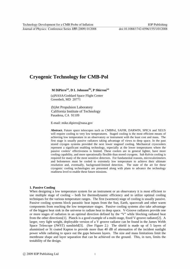
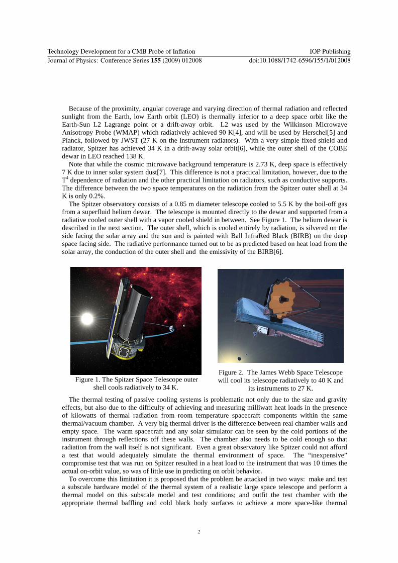
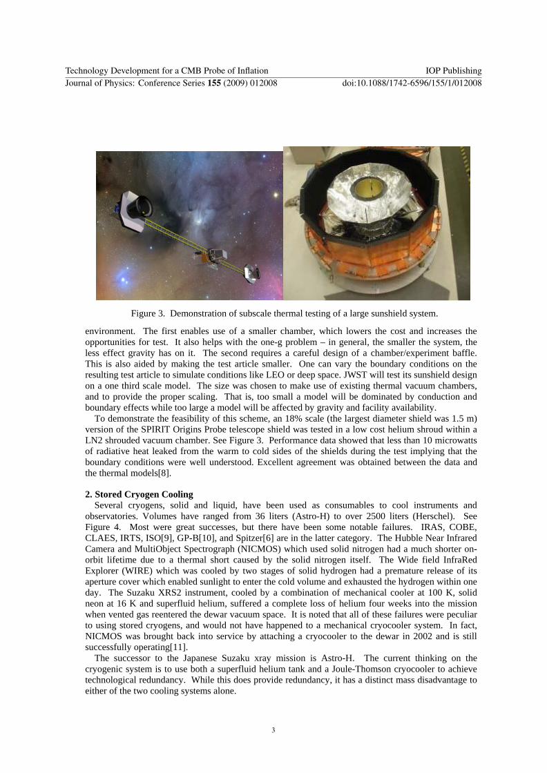
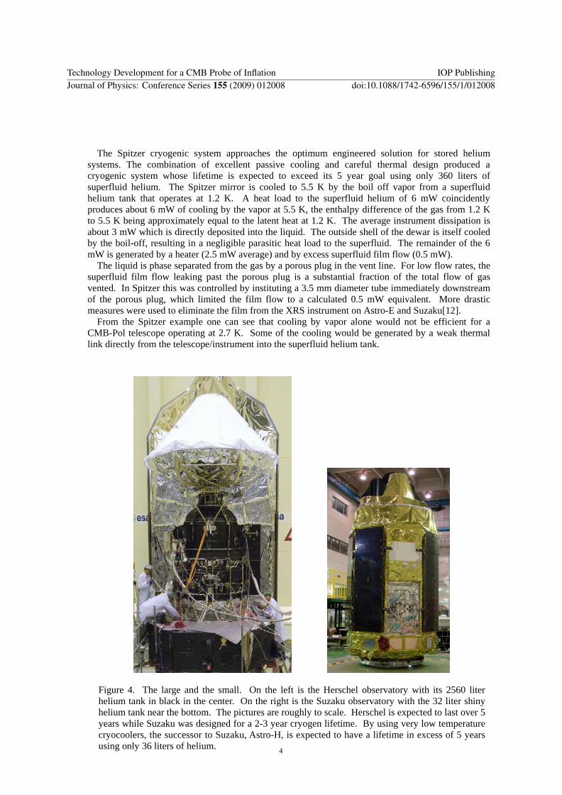
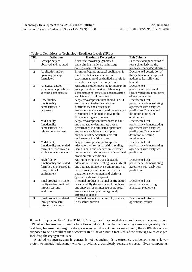
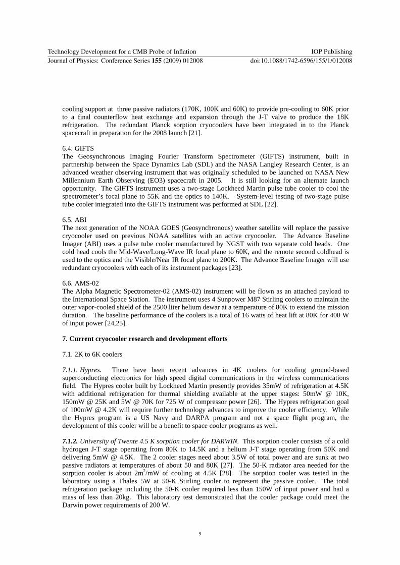
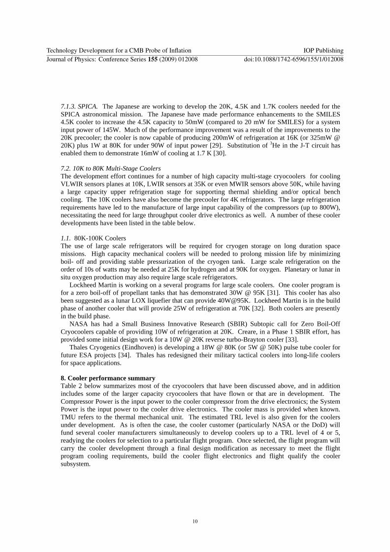
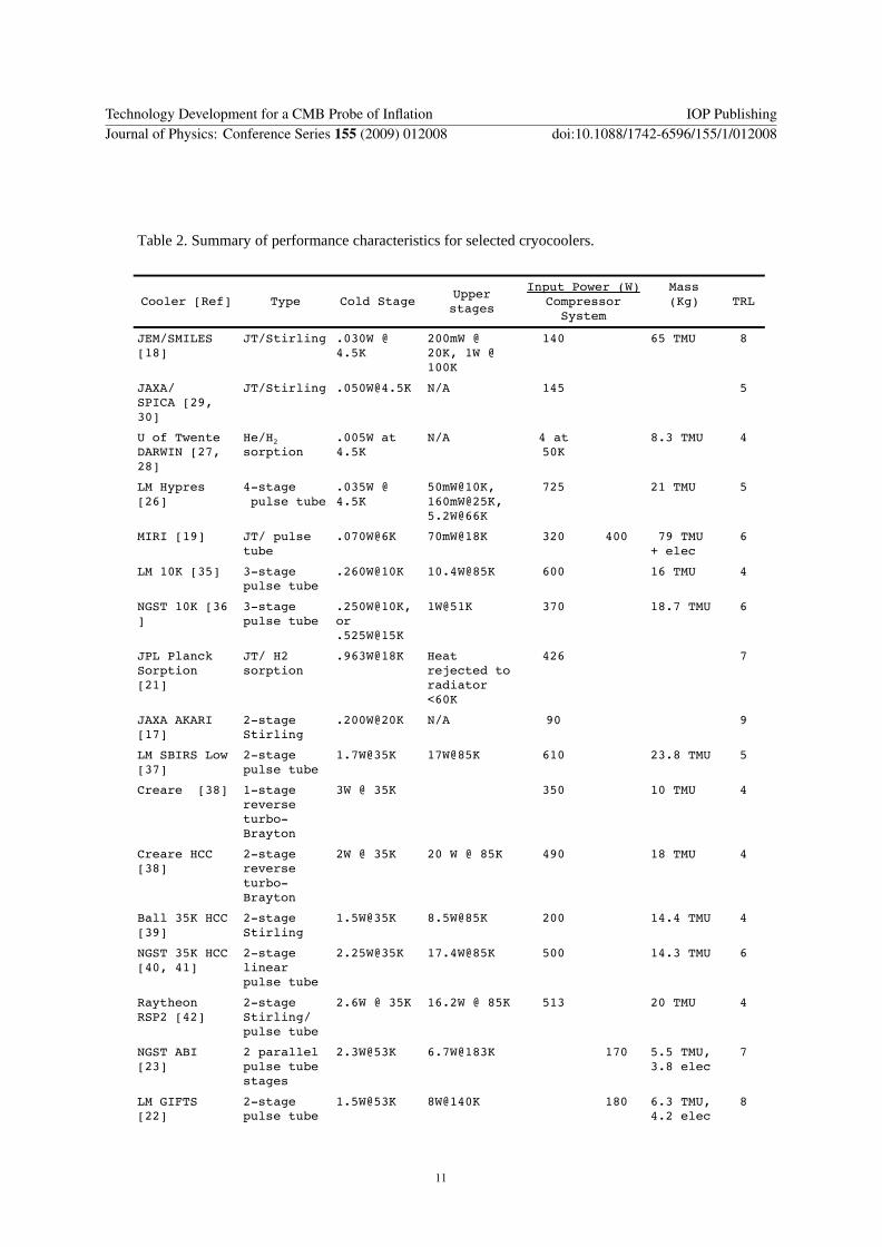
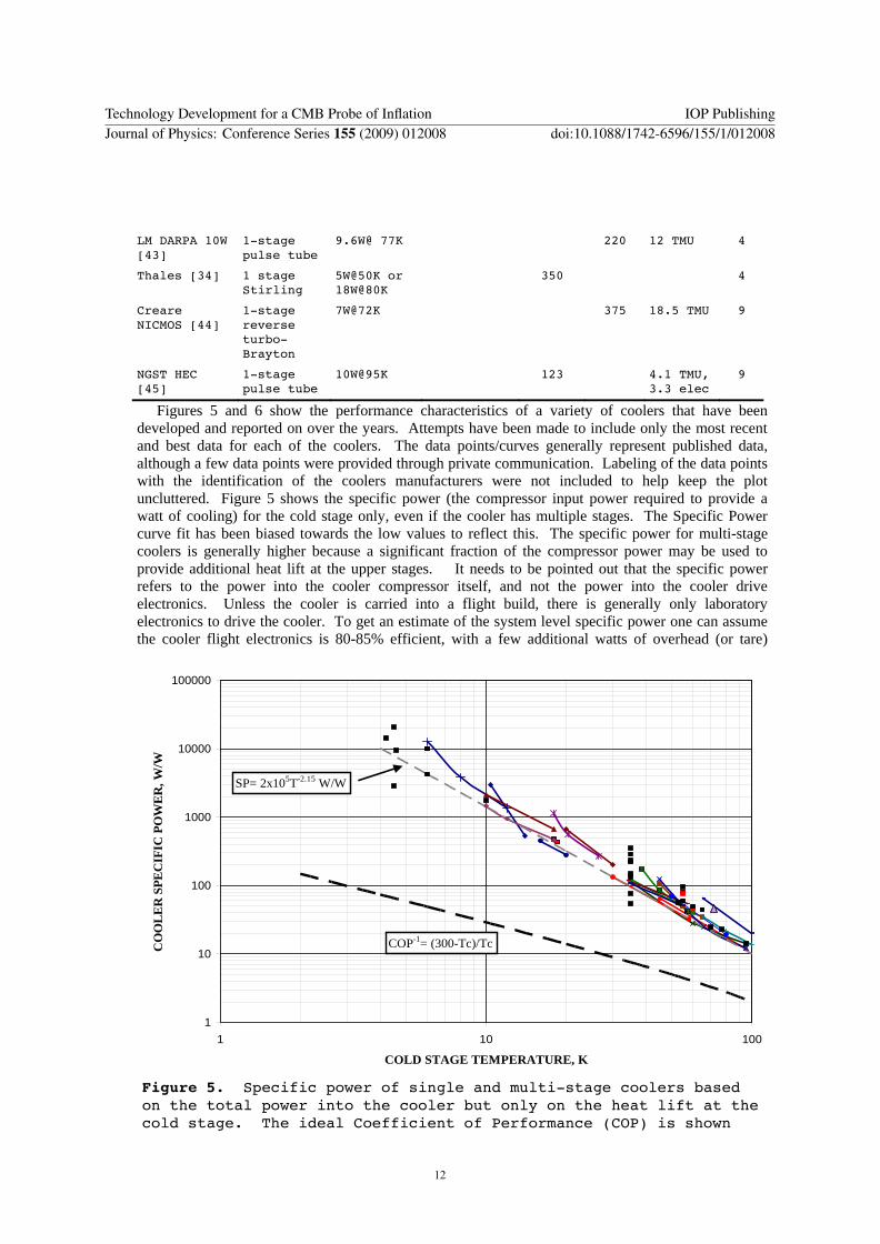
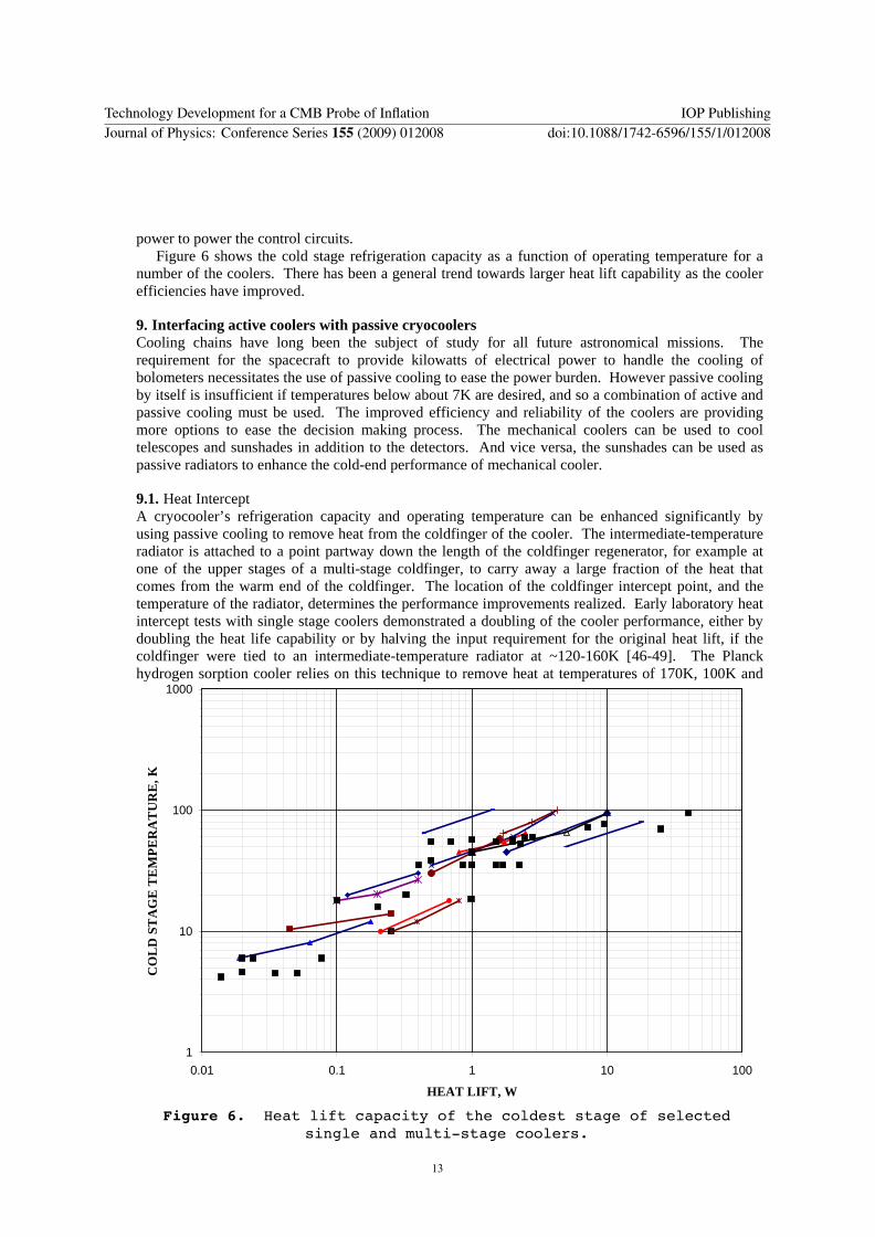
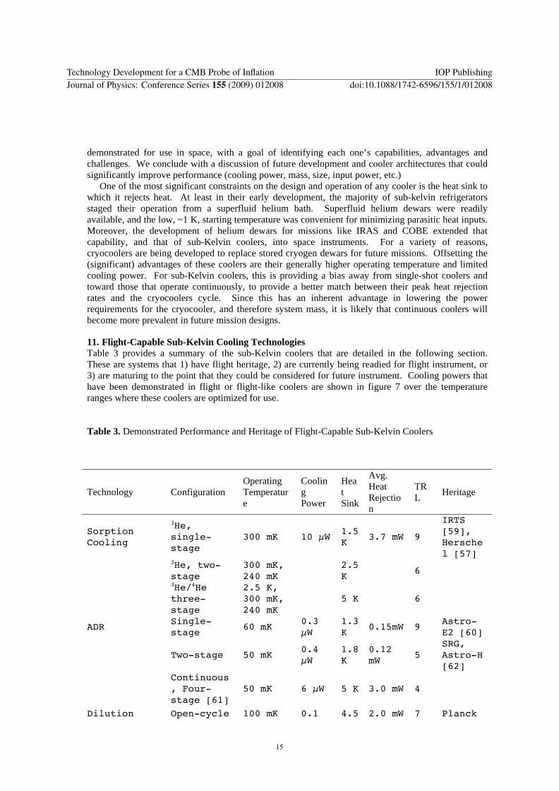
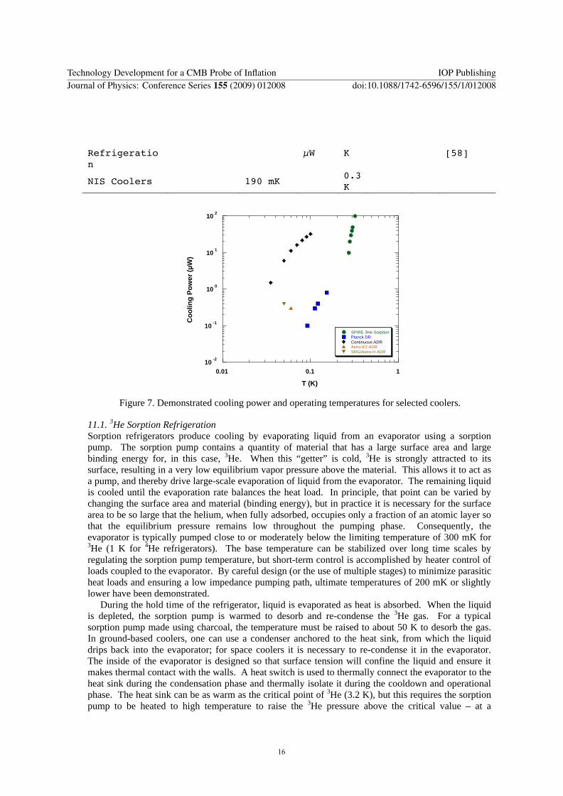
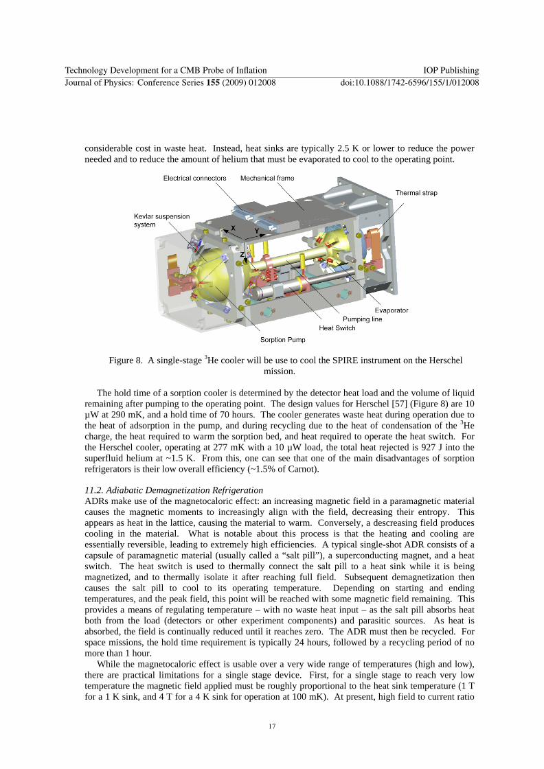
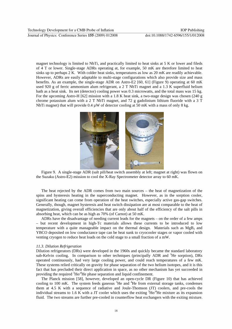
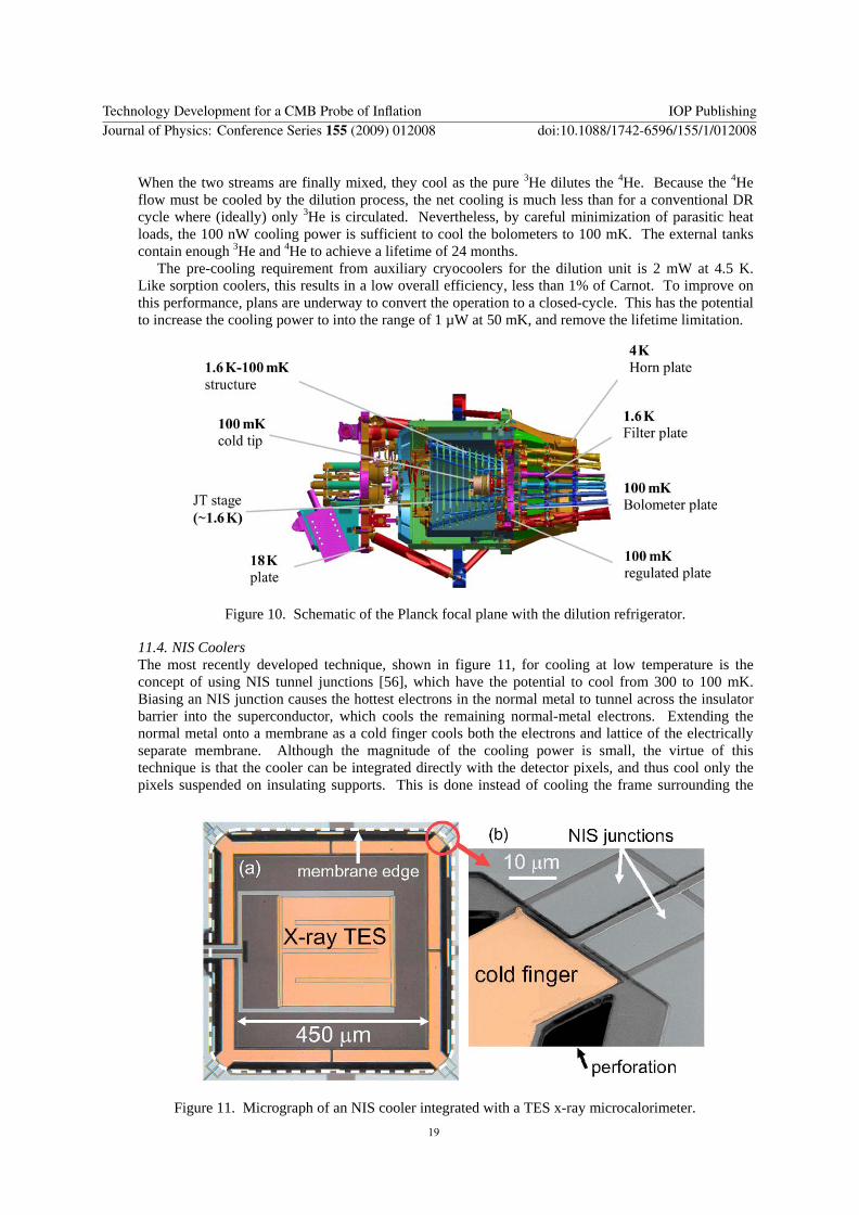
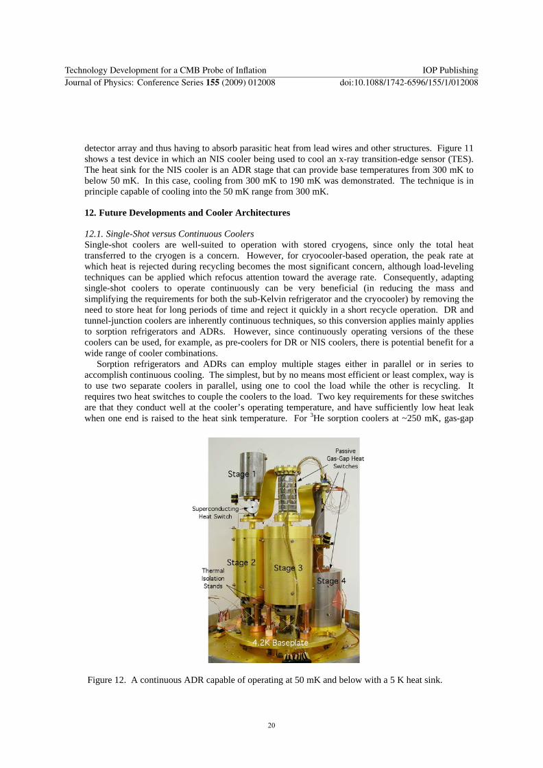
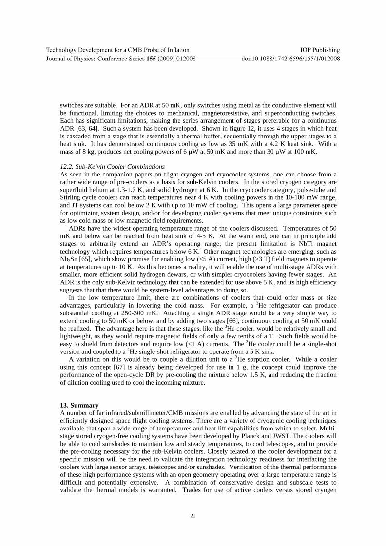